Week No. 6 Chapter Six: Power Factor Improvement · 2016-10-24 · Chapter Six: Power Factor...
30
Week No. 6 Chapter Six: Power Factor Improvement The electrical energy is almost wholly generated, transmitted and distributed in the form of alternating current. Therefore, the question of power factor immediately comes into picture. Most of the loads (e.g. induction motors, arc lamps) are inductive in nature and hence have low lagging power factor. The low power factor is highly undesirable as it causes an increase in current, resulting in additional losses of active . In order to ensure most favorable conditions for a supply system from engineering and economical standpoint, it is important to have power factor as close to unity as possible. Thus, it is important to discuss the various methods of power factor improvement 10/24/2016 Power System/ Dr. Ramzi A. Abdul-Halem 1
Transcript of Week No. 6 Chapter Six: Power Factor Improvement · 2016-10-24 · Chapter Six: Power Factor...

Week No. 6 Chapter Six: Power Factor Improvement
The electrical energy is almost wholly generated, transmitted and distributed in the form of alternating current.
Therefore, the question of power factor immediately comes into picture.
Most of the loads (e.g. induction motors, arc lamps) are inductive in nature and hence have low lagging power factor.
The low power factor is highly undesirable as it causes an increase in current, resulting in additional losses of active .
In order to ensure most favorable conditions for a supply system from engineering and economical standpoint, it is important to have power factor as close to unity as possible.
Thus, it is important to discuss the various methods of power factor improvement
10/24/2016 Power System/ Dr. Ramzi A. Abdul-Halem 1

6.1 Power Factor The cosine of angle between voltage and current in an a.c. circuit is known as power factor.
The term cos φ is called the power factor of the circuit.
Consider an inductive circuit taking a lagging current I from supply voltage V; the angle of lag being φ.
The phasor diagram of the circuit is shown in
Fig. 6.1.
The circuit current I can be resolved into two
perpendicular components, namely ;
• (a) I cos φ in phase with V
• (b) I sin φ 90o out of phase with V
10/24/2016 Power System/ Dr. Ramzi A. Abdul-Halem 2

The component I cos φ is known as active or wattful component, whereas component I sin φ is called the reactive or wattless component.
Circuit having small reactive current (i.e., I sin φ) will have high power factor and vice-versa.
6.2 Power Triangle
The analysis of power factor can also be made in terms of power drawn by the a.c. circuit.
The power triangle OAB shown in Fig. 6.2 where
• OA = VI cos φ and represents the active power
in watts or kW
• AB = VI sin φ and represents the reactive power
in VAR or kVAR
• OB = VI and represents the apparent power in
VA or kVA
10/24/2016 Power System/ Dr. Ramzi A. Abdul-Halem 3

The following points may be noted form the power triangle :
(i) The apparent power in an a.c. circuit has two components viz., active and reactive power at right angles to each other.
OB2 = OA2 + AB2
or (apparent power)2 = (active power)2 + (reactive power)2
or (kVA)2 = (kW)2 + (kVAR)2
• (ii) Power factor, cos φ = OA OB
= active power
apparent power =
kW kVA
Thus the power factor of a circuit may also be defined as the ratio of active power to the apparent power.
• (iii) The lagging reactive power is responsible for the low power factor. It is clear from the power triangle that smaller the reactive power component, the higher is the power factor of the circuit.
kVAR = kVA sin φ = kW
cos φ sin φ
∴ kVAR = kW tan φ
10/24/2016 Power System/ Dr. Ramzi A. Abdul-Halem 4

(iv) For leading currents, the power triangle becomes reversed. This fact provides a key to the power factor improvement. If a device taking leading reactive power (e.g. capacitor) is connected in parallel with the load, then: • The lagging reactive power of the load will be partly neutralized, thus • Improving the power factor of the load. (v) The power factor of a circuit can be defined in one of the following three ways: • (a) Power factor = cos φ = cosine of angle between V and I
• (b) Power factor = R Z =
Resistance Impedance
• (c) Power factor = VIcosφ
VI = Active power
Apparent Power
• (vi) The reactive power is neither consumed in the circuit nor it does any
useful work.
10/24/2016 Power System/ Dr. Ramzi A. Abdul-Halem 5

6.4 Causes of Low Power Factor Low power factor is undesirable from economic point of view. The following are the causes of low power factor: • (i) AC 1-φ and 3-φ induction motors operate at low lagging power factor specially
at light load. • (ii) Lamps and industrial heating furnaces operate at low lagging power factor. • (iii) The load on the power system is varying results in decreasing power factor.
6.5 Power Factor Improvement The low power factor is mainly due to the fact that most of the power loads are inductive and, therefore, take lagging currents. In order to improve the power factor, some device taking leading power should be connected in parallel with the load, such device can be a capacitor . The capacitor draws a leading current and partly or completely neutralizes the lagging reactive component of load current. This raises the power factor of the load.
10/24/2016 Power System/ Dr. Ramzi A. Abdul-Halem 6

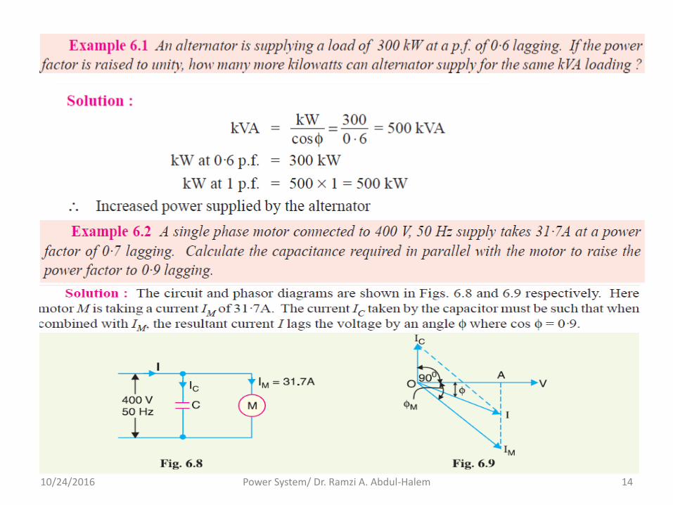
Illustration. To illustrate the power factor improvement by a capacitor, consider a single phase load taking lagging current I at a power factor cosφ1 as shown in Fig. 6.3.
The capacitor C is connected in parallel with the load. The capacitor draws current IC which leads the supply voltage by 90o. The resulting line current I′ is the phasor sum of I and IC and its angle of lag is φ2 as shown in the phasor diagram of Fig. 6.3. (iii).
10/24/2016 Power System/ Dr. Ramzi A. Abdul-Halem 7

It is clear that φ2 is less than φ1, so that cos φ2 is greater than cos φ1.
Hence, the power factor of the load is improved.
6.6 Power Factor Improvement Equipment
Normally, the power factor of the whole load on a large generating station is in the region of 0·8 to 0·9.
However, sometimes it is lower and in such cases it is generally desirable to take special steps to improve the power factor.
This can be achieved by the following equipment : 1. Static capacitors. 2. Synchronous condenser. 3. Phase advancers.
1. Static capacitor. The power factor can be improved by connecting capacitors in parallel with the equipment operating at lagging power factor.
The capacitor (generally known as static capacitor) draws a leading current and partly or completely neutralizes the lagging reactive component of load current, thus improving the power factor.
10/24/2016 Power System/ Dr. Ramzi A. Abdul-Halem 8

For three-phase loads, the capacitors can be connected in delta or star as shown in Fig. 6.4.
10/24/2016 Power System/ Dr. Ramzi A. Abdul-Halem 9

2. Synchronous condenser. A synchronous motor takes a leading current when over-excited and, therefore, behaves as a capacitor. • An over-excited synchronous motor running on no load is known as synchronous
condenser. • When such a machine is connected in parallel with the supply, as shown in Fig. 6.5,
it takes a leading current which partly neutralizes the lagging reactive component of the load. Thus the power factor is improved.
3. Phase advancers. Phase advancers are used to improve the power factor of induction motors. The phase advancer is simply an a.c. exciter.
10/24/2016 Power System/ Dr. Ramzi A. Abdul-Halem 10

6.7 Calculations of Power Factor Correction
Consider an inductive load taking a lagging current I at a power factor cos φ1.
In order to improve the power factor of this circuit, one of the power factor improvement equipments given in section 6.6 can be connected in parallel with the load which takes a leading reactive component.
Fig. 6.6 (i) shows a capacitor connected across the load.
10/24/2016 Power System/ Dr. Ramzi A. Abdul-Halem 11

The capacitor takes a current IC which leads the supply voltage V by 90o.
The current IC partly cancels the lagging reactive component of the load current as shown in the phasor diagram in Fig. 6.6 (ii).
The resultant circuit current becomes I′ and its angle of lag is φ2.
It is clear that φ2 is less than φ1so that new power factor cos φ2 is more than the previous power factor cos φ1.
Power triangle. The power factor correction can also be illustrated from power triangle.
Thus referring to Fig. 6.7, the power triangle OAB is for the power factor cos φ1, whereas power triangle OAC is for the improved power factor cos φ2.
10/24/2016 Power System/ Dr. Ramzi A. Abdul-Halem 12

It may be seen that active power (OA) does not change with power factor improvement.
However, the lagging kVAR of the load is reduced by the pf correction equipment, thus improving the pf to cos φ2.
Leading kVAR supplied by pf correction equipment
= BC = AB − AC
= kVAR1 − kVAR2
= OA (tan φ1 − tan φ2)
= kW (tan φ1 − tan φ2)
Knowing the leading kVAR supplied by the pf correction equipment, the desired results can be obtained.
10/24/2016 Power System/ Dr. Ramzi A. Abdul-Halem 13
10/24/2016 Power System/ Dr. Ramzi A. Abdul-Halem 14

10/24/2016 Power System/ Dr. Ramzi A. Abdul-Halem 15

10/24/2016 Power System/ Dr. Ramzi A. Abdul-Halem 16

10/24/2016 Power System/ Dr. Ramzi A. Abdul-Halem 17

10/24/2016 Power System/ Dr. Ramzi A. Abdul-Halem 18

10/24/2016 Power System/ Dr. Ramzi A. Abdul-Halem 19

Assignment Number Three
Pb 1:
Pb.2
Pb. 3
10/24/2016 Power System/ Dr. Ramzi A. Abdul-Halem 20

6.8 Importance of Power Factor Improvement The improvement of power factor is very important for both consumers and generating stations as discussed below :
(i) For consumers. A consumer has to pay electricity charges for his maximum demand in kVA plus the units consumed.
If the consumer improves the power factor, then there is a reduction† in his maximum kVA demand and consequently there will be annual saving due to maximum demand charges.
Although power factor improvement involves extra annual expenditure on account of p.f. correction equipment, yet improvement of p.f. to a proper value results in the net annual saving for the consumer.
10/24/2016 Power System/ Dr. Ramzi A. Abdul-Halem 21

(ii) For generating stations. A generating station is as much concerned with power factor improvement as the consumer.
The generators in a power station are rated in kVA but the useful output depends upon kW output.
As station output is kW = kVA × cos φ, therefore, number of units supplied by it depends upon the power factor.
The greater the power factor of the generating station, the higher is the kWh it delivers to the system.
This leads to the conclusion that improved power factor increases the earning capacity of the power station
10/24/2016 Power System/ Dr. Ramzi A. Abdul-Halem 22

6.9 Most Economical Power Factor (Week No 6) If a consumer improves the power factor, there is reduction in his maximum kVA demand and hence there will be annual saving over the maximum demand charges.
However, when power factor is improved, it involves capital investment on the power factor correction equipment.
The consumer will suffer expenditure every year in the shape of annual interest and depreciation on the investment made over the p.f. correction equipment.
Therefore, the net annual saving will be equal to the annual saving in maximum demand charges minus annual expenditure incurred on p.f. correction equipment.
The value to which the power factor should be improved so as to have maximum net annual saving is known as the most economical power factor.
10/24/2016 Power System/ Dr. Ramzi A. Abdul-Halem 23
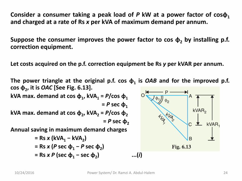
Consider a consumer taking a peak load of P kW at a power factor of cosφ1
and charged at a rate of Rs x per kVA of maximum demand per annum.
Suppose the consumer improves the power factor to cos φ2 by installing p.f. correction equipment.
Let costs acquired on the p.f. correction equipment be Rs y per kVAR per annum.
The power triangle at the original p.f. cos φ1 is OAB and for the improved p.f. cos φ2, it is OAC [See Fig. 6.13].
kVA max. demand at cos φ1, kVA1 = P/cos φ1
= P sec φ1
kVA max. demand at cos φ2, kVA2 = P/cos φ2
= P sec φ2
Annual saving in maximum demand charges
= Rs x (kVA1 − kVA2)
= Rs x (P sec φ1 − P sec φ2)
= Rs x P (sec φ1 − sec φ2) ...(i)
10/24/2016 Power System/ Dr. Ramzi A. Abdul-Halem 24

Reactive power at cos φ1, kVAR1 = P tan φ1
Reactive power at cos φ2, kVAR2 = P tan φ2
Leading kVAR taken by p.f. correction equipment = P (tan φ1 − tan φ2) Annual cost of p.f. correction equipment = Rs Py (tan φ1 − tan φ2) ...(ii) Net annual saving, S = exp. (i) − exp. (ii) = xP (sec φ1 − sec φ2) − yP (tan φ1 − tan φ2) In this expression, only φ2 is variable while all other quantities are fixed. Therefore, the net annual saving will be maximum if differentiation of above expression w.r.t. φ2 is zero i.e.
d(S)dφ2 = 0
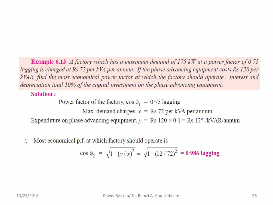
∴ Most economical power factor, It may be noted that the most economical power factor (cos φ2) depends upon the relative costs of supply and p.f. correction equipment but is independent of the original p.f. cos φ1.
10/24/2016 Power System/ Dr. Ramzi A. Abdul-Halem 25
10/24/2016 Power System/ Dr. Ramzi A. Abdul-Halem 26

10/24/2016 Power System/ Dr. Ramzi A. Abdul-Halem 27

10/24/2016 Power System/ Dr. Ramzi A. Abdul-Halem 28

10/24/2016 Power System/ Dr. Ramzi A. Abdul-Halem 29

10/24/2016 Power System/ Dr. Ramzi A. Abdul-Halem 30