
Week 3 Further into the MSP430 - Hacettepe Universityalkar/ELE417/week3_hacettepe...ISA 12 “Add...
91
Week 3 Further into the MSP430 MSP430 Teaching Materials Hacettepe University Copyright 2009 Texas Instruments All Rights Reserved
-
Upload
trannguyet -
Category
Documents
-
view
224 -
download
3
Transcript of Week 3 Further into the MSP430 - Hacettepe Universityalkar/ELE417/week3_hacettepe...ISA 12 “Add...

Week 3Further into the MSP430
MSP430 Teaching Materials
Hacettepe University
Copyright 2009 Texas Instruments All Rights Reserved
2Copyright 2009
Texas Instruments All Rights Reserved
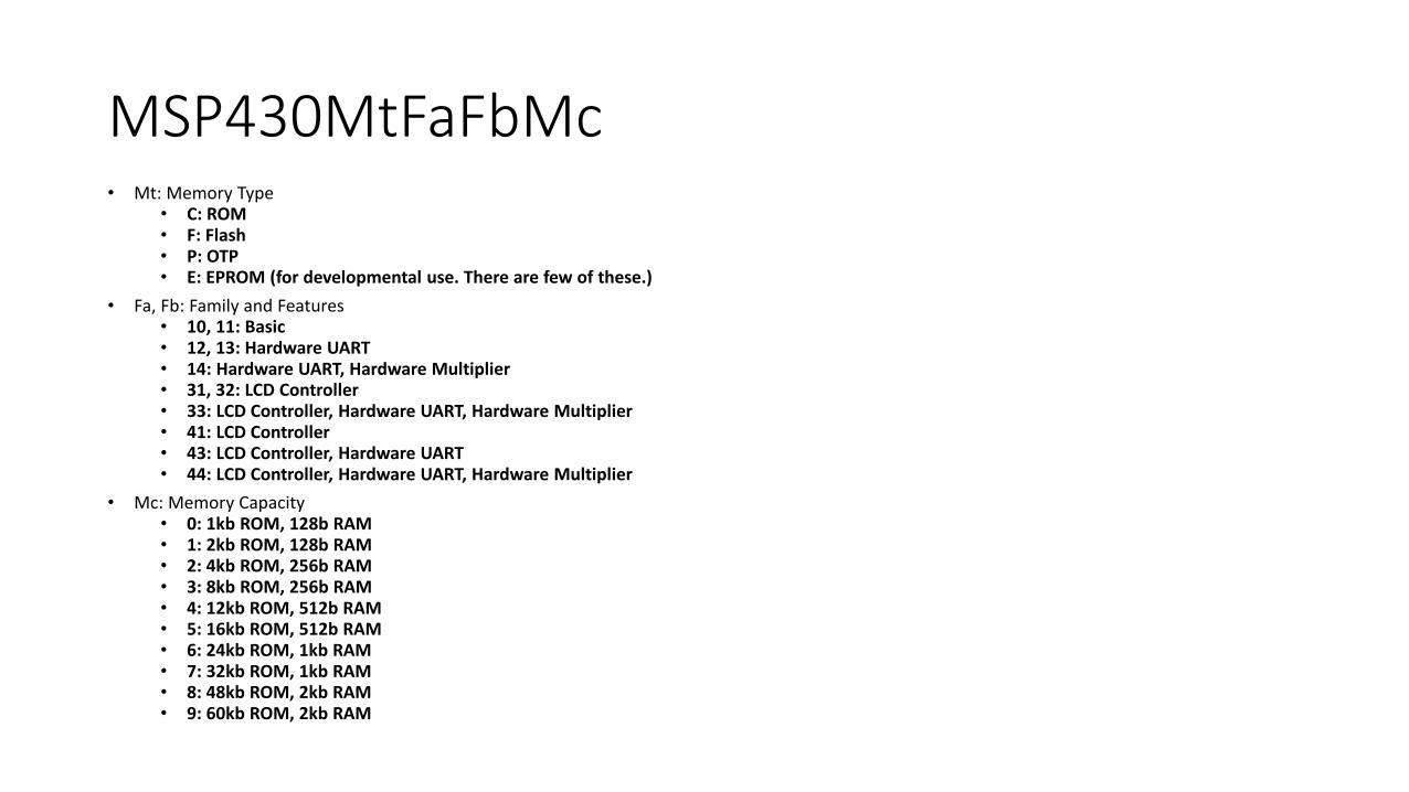
MSP430MtFaFbMc• Mt: Memory Type
• C: ROM• F: Flash• P: OTP• E: EPROM (for developmental use. There are few of these.)
• Fa, Fb: Family and Features• 10, 11: Basic• 12, 13: Hardware UART• 14: Hardware UART, Hardware Multiplier• 31, 32: LCD Controller• 33: LCD Controller, Hardware UART, Hardware Multiplier• 41: LCD Controller• 43: LCD Controller, Hardware UART• 44: LCD Controller, Hardware UART, Hardware Multiplier
• Mc: Memory Capacity• 0: 1kb ROM, 128b RAM• 1: 2kb ROM, 128b RAM• 2: 4kb ROM, 256b RAM• 3: 8kb ROM, 256b RAM• 4: 12kb ROM, 512b RAM• 5: 16kb ROM, 512b RAM• 6: 24kb ROM, 1kb RAM• 7: 32kb ROM, 1kb RAM• 8: 48kb ROM, 2kb RAM• 9: 60kb ROM, 2kb RAM

3Copyright 2009
Texas Instruments All Rights Reserved
Example
• The MSP430F435 is a Flash memory device with an LCD controller, a hardware UART, 16 kb of code memory, and 512 bytes of RAM.
4Copyright 2009
Texas Instruments All Rights Reserved
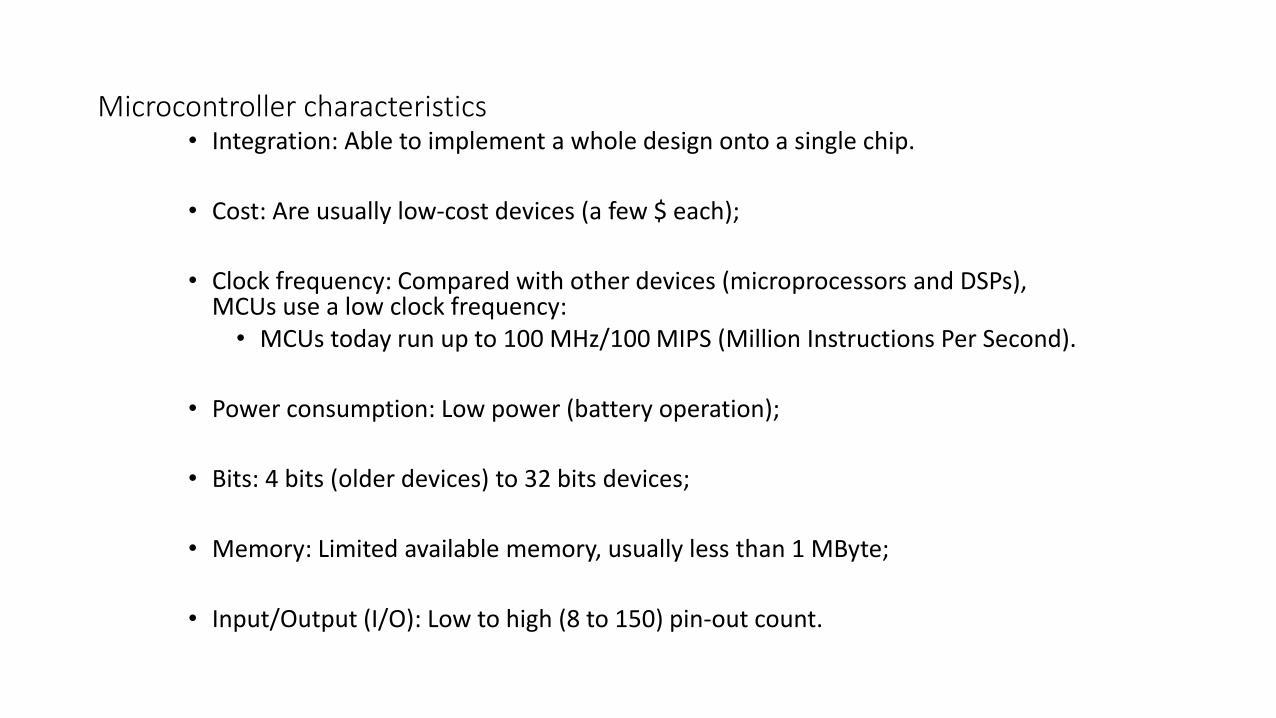
Microcontroller characteristics• Integration: Able to implement a whole design onto a single chip.
• Cost: Are usually low-cost devices (a few $ each);
• Clock frequency: Compared with other devices (microprocessors and DSPs), MCUs use a low clock frequency:
• MCUs today run up to 100 MHz/100 MIPS (Million Instructions Per Second).
• Power consumption: Low power (battery operation);
• Bits: 4 bits (older devices) to 32 bits devices;
• Memory: Limited available memory, usually less than 1 MByte;
• Input/Output (I/O): Low to high (8 to 150) pin-out count.
5Copyright 2009
Texas Instruments All Rights Reserved
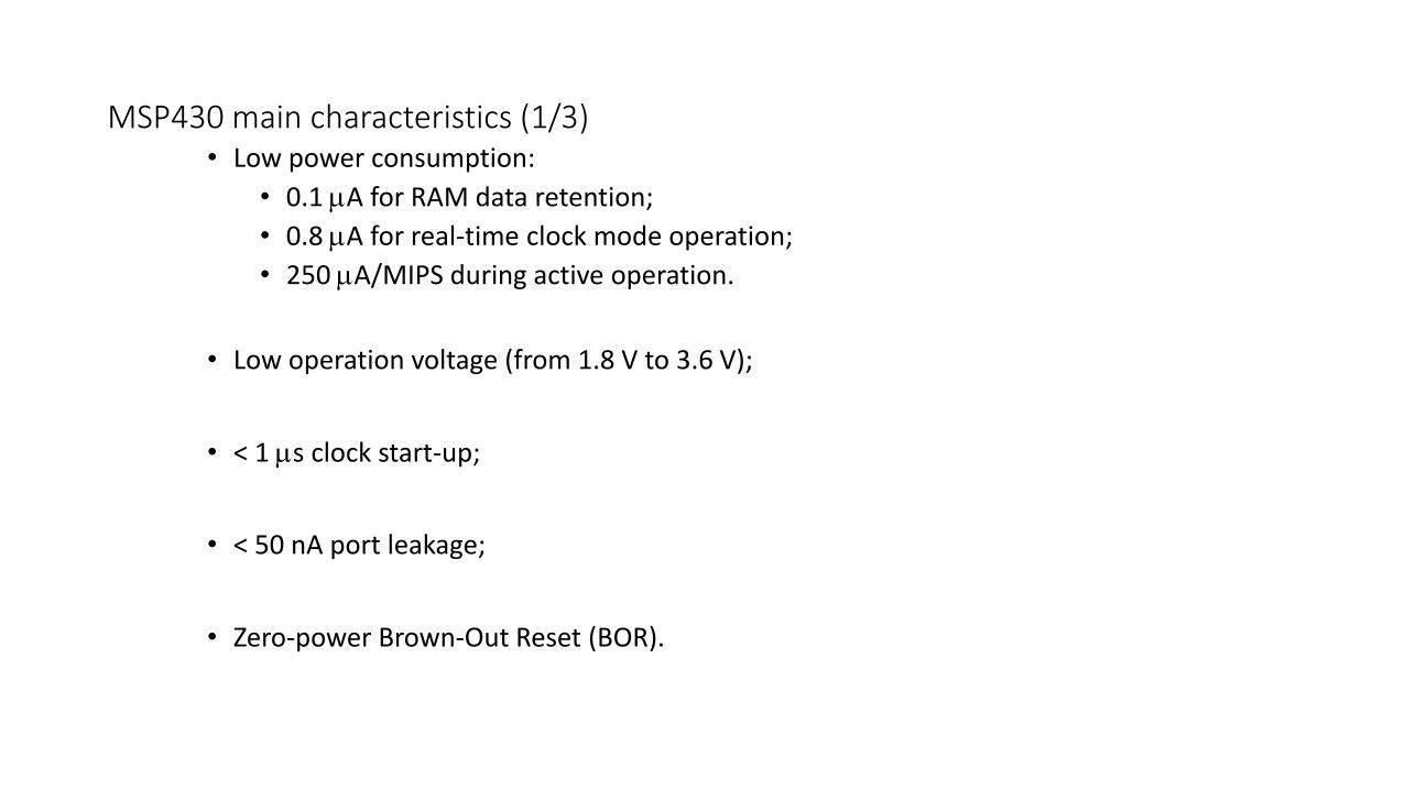
MSP430 main characteristics (1/3)• Low power consumption:
• 0.1 A for RAM data retention;
• 0.8 A for real-time clock mode operation;
• 250 A/MIPS during active operation.
• Low operation voltage (from 1.8 V to 3.6 V);
• < 1 s clock start-up;
• < 50 nA port leakage;
• Zero-power Brown-Out Reset (BOR).

6Copyright 2009
Texas Instruments All Rights Reserved
MSP430 main characteristics (3/3)• Flexibility:
• Up to 256 kByte Flash;• Up to 100 pins;• USART, I2C, Timers;• LCD driver;• Embedded emulation;• And many more peripherals modules…
• Microcontroller performance:• Instruction processing on either bits, bytes or words• Reduced instructions set;• Compiler efficient;• Wide range of peripherals;• Flexible clock system.
• 1.8–3.6V operation
7Copyright 2009
Texas Instruments All Rights Reserved
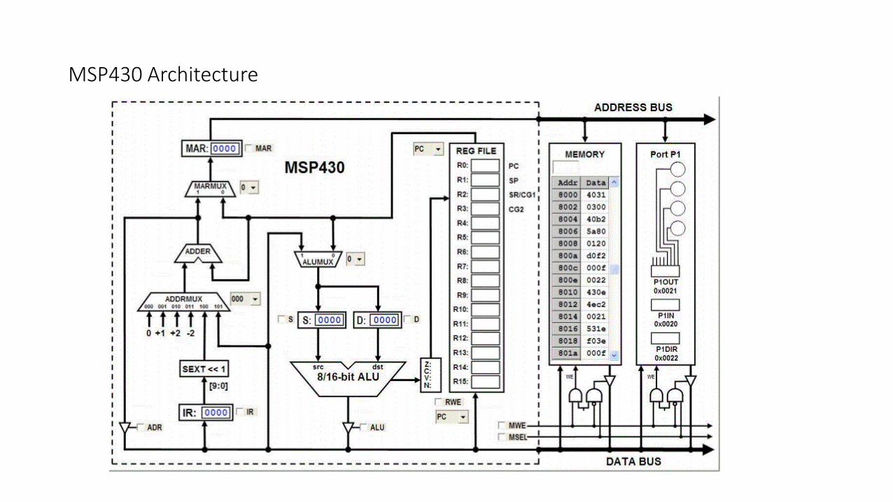
MSP430 Architecture
MACHINE VS. ASSEMBLY LANGUAGE
Copyright 2009 Texas Instruments All Rights Reserved 8
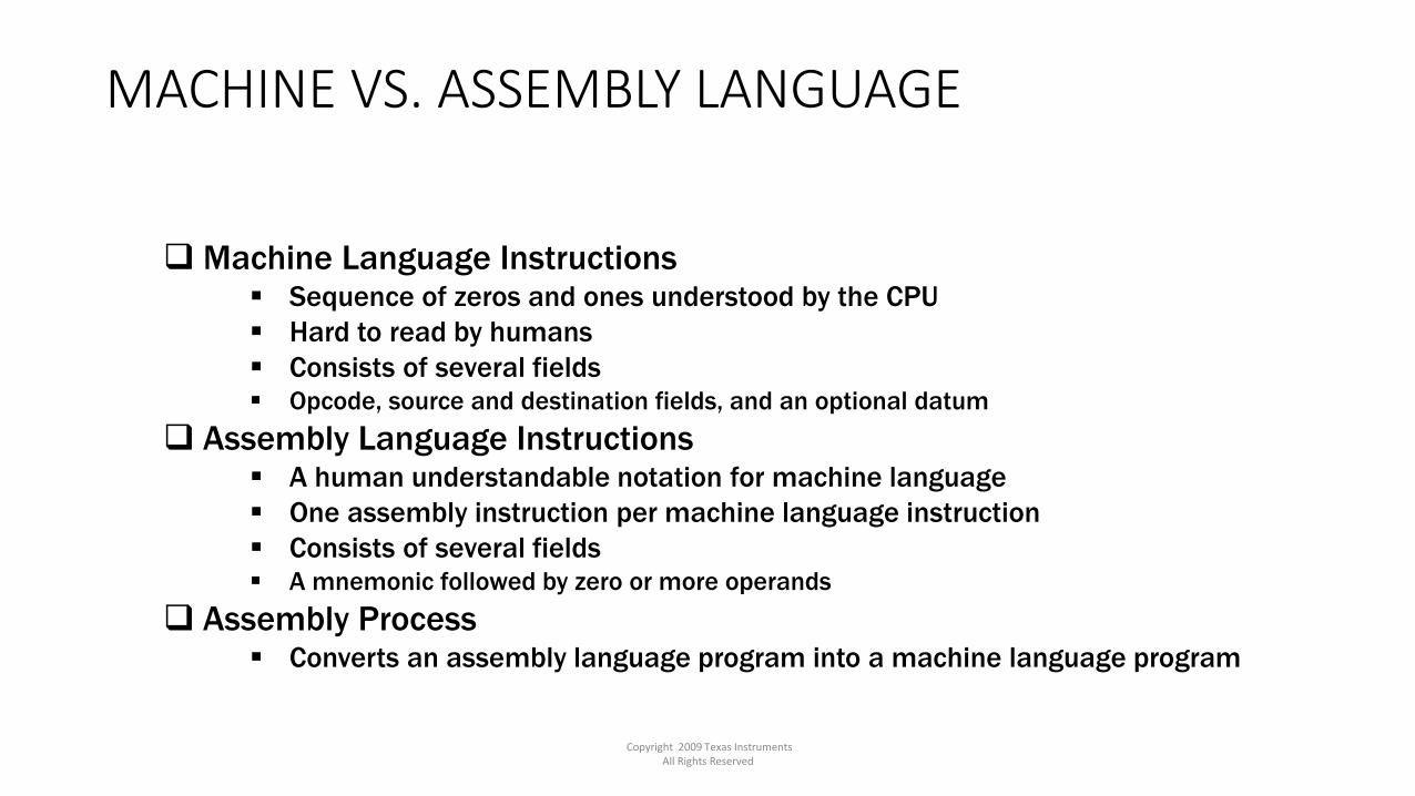
Machine Language Instructions Sequence of zeros and ones understood by the CPU
Hard to read by humans
Consists of several fields Opcode, source and destination fields, and an optional datum
Assembly Language Instructions A human understandable notation for machine language
One assembly instruction per machine language instruction
Consists of several fields A mnemonic followed by zero or more operands
Assembly Process Converts an assembly language program into a machine language program

Machine vs Assembly language
Copyright 2009 Texas Instruments All Rights Reserved 9

ISA 10
Computer Instructions• Computer program consists of a sequence of instructions
• instruction = verb + operand(s)
• stored in memory as 1’s and 0’s
• called machine code.
• Instructions are fetched from memory• The program counter (PC) holds the memory address of the next
instruction (or operand).
• The instruction is stored internal to the CPU in the instruction register (IR).
• Programs execute sequentially through memory• Execution order is altered by changing the program counter (PC).
• A computer clock controls the speed and phases of instruction execution.
Computer Instructions
ISA 11
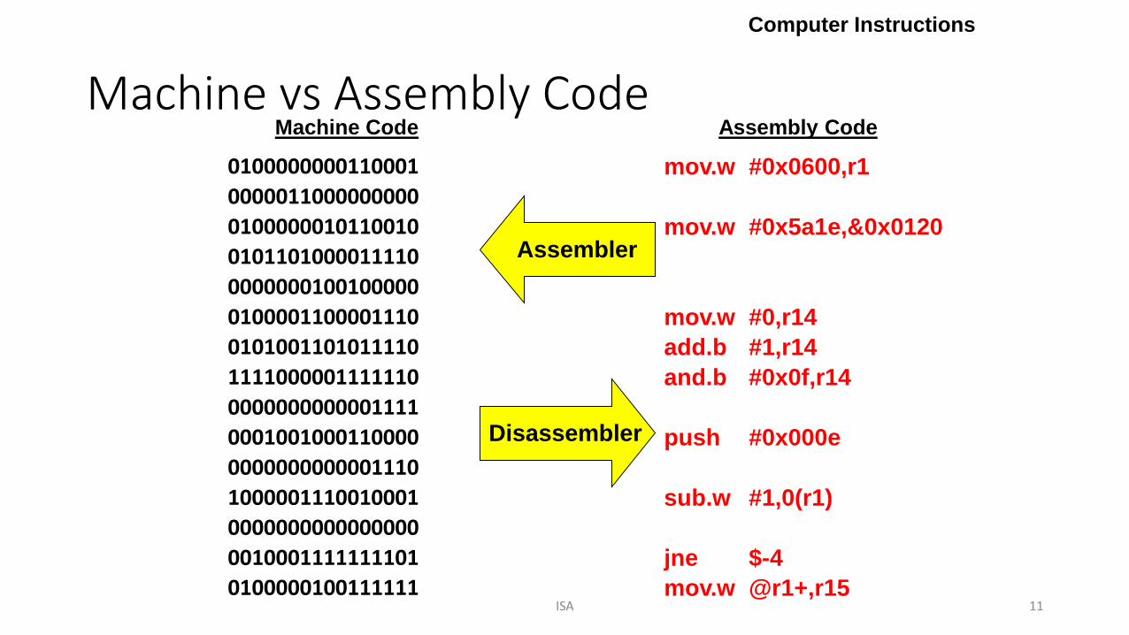
Machine vs Assembly Code
Computer Instructions
Disassembler
0100000100111111
0000011000000000
0100000010110010
0100001100001110
0101001101011110
1111000001111110
0001001000110000
1000001110010001
0010001111111101
0100000000110001
0101101000011110
0000000100100000
0000000000001111
0000000000001110
0000000000000000
Machine Code
mov.w #0x0600,r1
mov.w #0x5a1e,&0x0120
mov.w #0,r14
add.b #1,r14
and.b #0x0f,r14
push #0x000e
sub.w #1,0(r1)
jne $-4
mov.w @r1+,r15
Assembly Code
Assembler

ISA 12
“Add the value in Register 4 to the value in Register 5”
Anatomy of Machine Instruction
Computer Instructions
2. 1st object – Source operand
3. 2nd object – Destination operand
1. Verb – Opcode (defines operation & operands)
add r4,r5
How manyinstructions arepossible with a4-bit op-code?
How manysource/destinationregisters canselected with a4-bit field?
BYU CS 224
0101010000000101

ISA 13
MSP430 Bus Architecture
• Memory Data Bus (bi-directional)• Addressability = # of bits stored in each
memory location (8-bits).
• Words are always addressed at an even address (little endian).
Memory Address Bus (uni-directional)
Address Space = number of possiblememory locations (memory size)
BYU CS 224
MSP430 ISA
Sixteen 16-bit registers Program Counter (R0), Stack Pointer (R1), Status Register (R2), Constant
Generator (R3), General Purpose Registers (R4-R15).
16-bit ALU (Arithmetic and Logic Unit)
Sets condition codes: Z, C, N, V
The master clock (MCLK) drives the CPU and ALU logic.

Input / Output Get information in and out of the computer.
External devices attached to a computer are called peripherals.
Lower 512 bytes (0x0000 - 0x01FF) of address space 16-bit peripherals (0x0100 - 0x01FF)
8-bit peripherals (0x0010 - 0x00FF)
Special Function Registers – Lower 16 bytes
ISA 14
MSP430 Memory Architecture Memory
64k byte addressable, address space(0x0000 - 0xFFFF)
Flash / ROM – Used for both code/data
Interrupt vectors - Upper 16 words
RAM (0x0200) – Volatile storage
0x0000
0xFFFF
I/O
Fla
sh
(R
OM
)R
AM
BYU CS 224
MSP430 ISA
0x0200
ISA 15
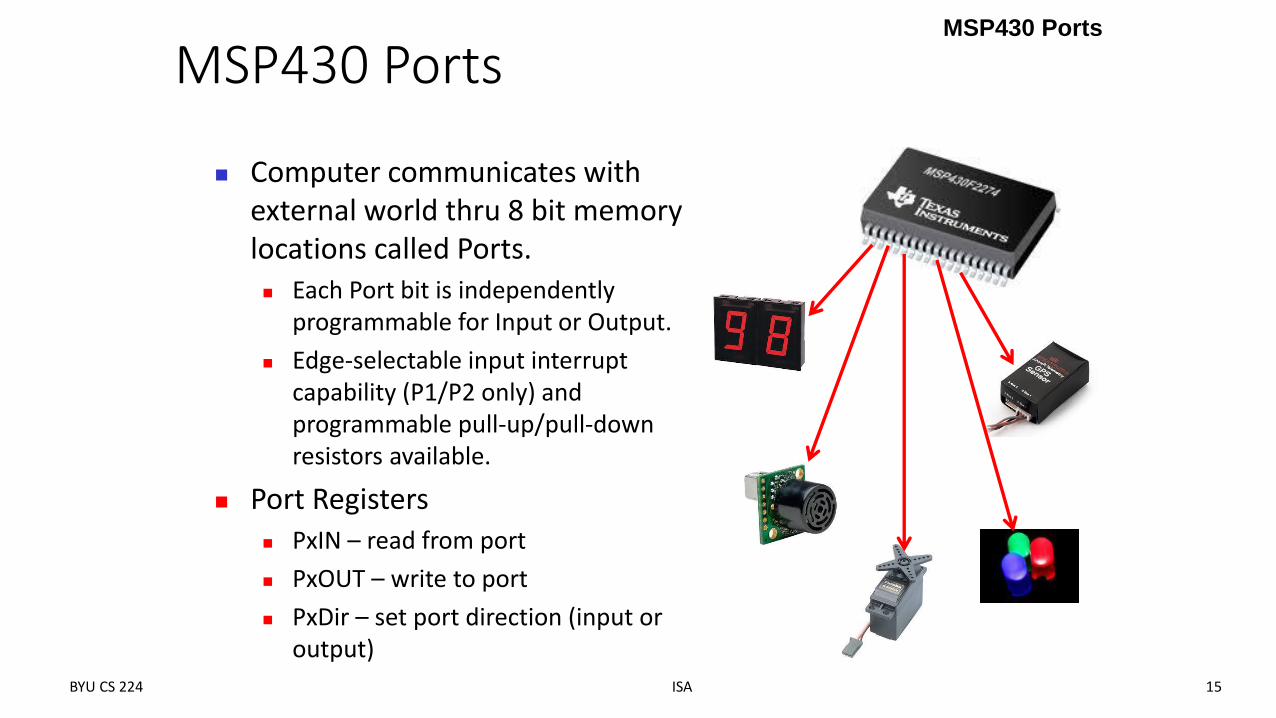
MSP430 Ports
Computer communicates with external world thru 8 bit memory locations called Ports. Each Port bit is independently
programmable for Input or Output.
Edge-selectable input interrupt capability (P1/P2 only) and programmable pull-up/pull-down resistors available.
Port Registers PxIN – read from port
PxOUT – write to port
PxDir – set port direction (input or output)
BYU CS 224
MSP430 Ports
ISA 16
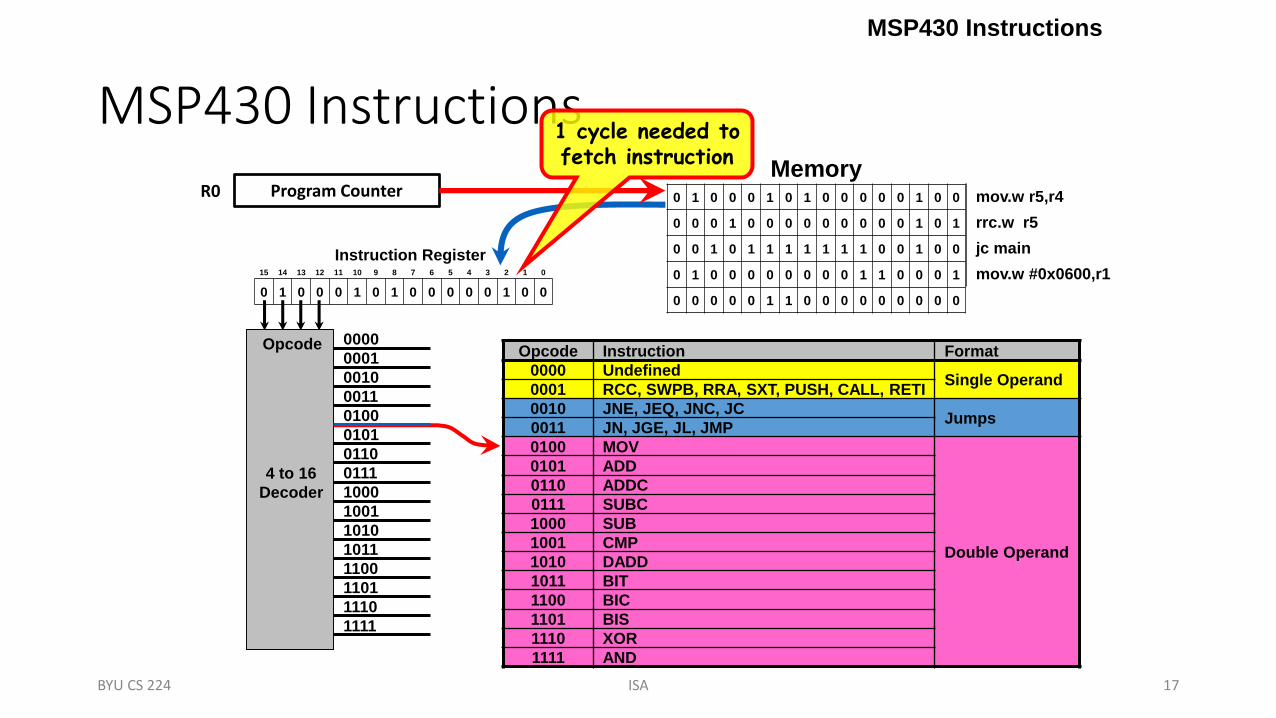
MSP430 Instructions• The first 4-bits (nybble) of an instruction is called the opcode
and specifies the instruction and format.
• The MSP430 ISA defines 27 instructions with three instruction formats: double operand, single operand, and jumps.
• Single and double operand instructions process word (16-bits) or byte (8-bit) data operations. (Default is word)
• Orthogonal instruction set – every instruction is usable with every addressing mode throughout the entire memory map.
• Includes high register count, no paging, stack processing, memory to memory operations, constant generator.
Instruction Formats
BYU CS 224
ISA 17
MSP430 Instructions
15 14 13 12 11 10 9 8 7 6 5 4 3 2 1 0
0 1 0 0 0 1 0 1 0 0 0 0 0 1 0 0
Instruction Register
Memory0 1 0 0 0 1 0 1 0 0 0 0 0 1 0 0
0 0 0 1 0 0 0 0 0 0 0 0 0 1 0 1
0 0 1 0 1 1 1 1 1 1 1 0 0 1 0 0
0 1 0 0 0 0 0 0 0 0 1 1 0 0 0 1
0 0 0 0 0 1 1 0 0 0 0 0 0 0 0 0
mov.w r5,r4
rrc.w r5
jc main
mov.w #0x0600,r1
Opcode Instruction Format
0000 UndefinedSingle Operand
0001 RCC, SWPB, RRA, SXT, PUSH, CALL, RETI
0010 JNE, JEQ, JNC, JCJumps
0011 JN, JGE, JL, JMP
0100 MOV
Double Operand
0101 ADD
0110 ADDC
0111 SUBC
1000 SUB
1001 CMP
1010 DADD
1011 BIT
1100 BIC
1101 BIS
1110 XOR
1111 AND
1111
1110
1101
1100
1011
1010
1001
1000
0111
0110
0101
0100
0011
0010
0001
0000
4 to 16
Decoder
Opcode
BYU CS 224
Program Counter
MSP430 Instructions
R0
1 cycle needed tofetch instruction
ISA 18
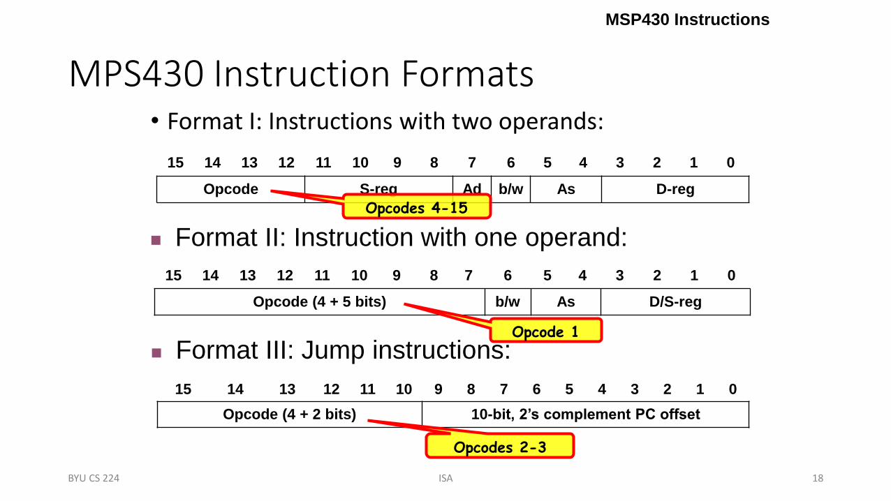
MPS430 Instruction Formats• Format I: Instructions with two operands:
15 14 13 12 11 10 9 8 7 6 5 4 3 2 1 0
Opcode S-reg Ad b/w As D-reg
MSP430 Instructions
15 14 13 12 11 10 9 8 7 6 5 4 3 2 1 0
Opcode (4 + 5 bits) b/w As D/S-reg
15 14 13 12 11 10 9 8 7 6 5 4 3 2 1 0
Opcode (4 + 2 bits) 10-bit, 2’s complement PC offset
Format II: Instruction with one operand:
Format III: Jump instructions:
BYU CS 224
Opcodes 4-15
Opcode 1
Opcodes 2-3

Logical and register control instructions
AND(.B or .W) src,dst src.and.dstdst AND source with destination
BIC(.B or .W) src,dst .not.src.and.dstdst Clear bits in destination
BIS(.B or .W) src,dst src.or.dstdst Set bits in destination
BIT(.B or .W) src,dst src.and.dst Test bits in destination
XOR(.B or .W) src,dst src.xor.dstdst XOR source with destination
Data instructions
CMP(.B or .W) src,dst dst-src Compare source to destination
MOV(.B or .W) src,dst srcdst Move source to destination
ISA 19
Format I: Double OperandMnemonic Operation Description
Arithmetic instructions
ADD(.B or .W) src,dst src+dstdst Add source to destination
ADDC(.B or .W) src,dst src+dst+Cdst Add source and carry to destination
DADD(.B or .W) src,dst src+dst+Cdst (dec) Decimal add source and carry to destination
SUB(.B or .W) src,dst dst+.not.src+1dst Subtract source from destination
SUBC(.B or .W) src,dst dst+.not.src+Cdst Subtract source and not carry from destination
Double Operand Instructions
BYU CS 224

Program flow control instructions
CALL dst SP-2SP,
PC+2@SP
dstPC
Subroutine call to destination
RETI @SP+SR, @SP+SP Return from interrupt
ISA 20
Format II: Single Operand
Mnemonic Operation Description
Logical and register control instructions
RRA(.B or .W) dst MSBMSB…
LSBC
Roll destination right
RRC(.B or .W) dst CMSB…LSBC Roll destination right through carry
SWPB(.W) dst Swap bytes Swap bytes in destination
SXT(.W) dst bit 7bit 8…bit 15 Sign extend destination
PUSH(.B or .W) src SP-2SP, src@SP Push source on stack
Single Operand Instructions
BYU CS 224

ISA 21
Format III: Jump Instruction
• Jump instructions are used to direct program flow to another part of the program (by changing the PC).
• The condition on which a jump occurs depends on the Condition field consisting of 3 bits:
• JNZ/JNE 000: jump if not equal (Z = 0)• JZ/JEQ 001: jump if equal (Z = 1)• JNC/JLO 010: jump if no carry (C = 0)• JC/JHS 011: jump if carry (C = 1)• JN100: jump if negative (N = 1)• JGE 101: jump if greater than or equal (N = V)• JL 110: jump if lower (N V)• JMP 111: unconditional jump
Jump Instructions
15 14 13 12 11 10 9 8 7 6 5 4 3 2 1 0
Opcode + Condition 10-bit, 2’s complement PC offset
BYU CS 224

Different Machine Instructions for MSP430
Copyright 2009 Texas Instruments All Rights Reserved 22

Basic Assembly Process
Copyright 2009 Texas Instruments All Rights Reserved 23

TOOLS FOR MSP430
Copyright 2009 Texas Instruments All Rights Reserved 24


ISA 27
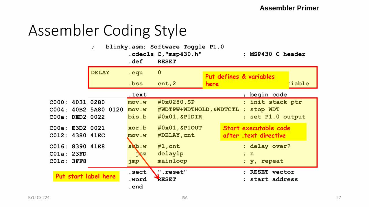
Assembler Coding Style
Assembler Primer
; blinky.asm: Software Toggle P1.0
.cdecls C,"msp430.h" ; MSP430 C header
.def RESET
DELAY .equ 0
.bss cnt,2 ; counter variable
.text ; begin code
RESET: mov.w #0x0280,SP ; init stack ptr
mov.w #WDTPW+WDTHOLD,&WDTCTL ; stop WDT
bis.b #0x01,&P1DIR ; set P1.0 output
mainloop: xor.b #0x01,&P1OUT ; toggle P1.0
mov.w #DELAY,cnt ; delay counter
delaylp: sub.w #1,cnt ; delay over?
jnz delaylp ; n
jmp mainloop ; y, repeat
.sect ".reset" ; RESET vector
.word RESET ; start address
.end
BYU CS 224
Put start label here
Start executable code after .text directive
Put defines & variables here
C000: 4031 0280
C004: 40B2 5A80 0120
C00a: DED2 0022
C00e: E3D2 0021
C012: 4380 41EC
C016: 8390 41E8
C01a: 23FD
C01c: 3FF8


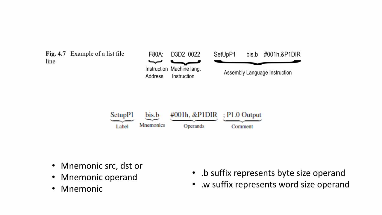
• Mnemonic src, dst or• Mnemonic operand• Mnemonic
• .b suffix represents byte size operand• .w suffix represents word size operand

33
Directives
• Directives are for the assembler only!
• They do not translate into machine code or data to be loaded into microcontroller memory
• They serve to organize the program,
• Depends on the assembler
• Some examples:• EQU and #define
• LABEL EQU <Value or Expression>
• #define <Symbolic Name> Value or expression or register
• #include • #include “filename”
• ORG

34
Directives
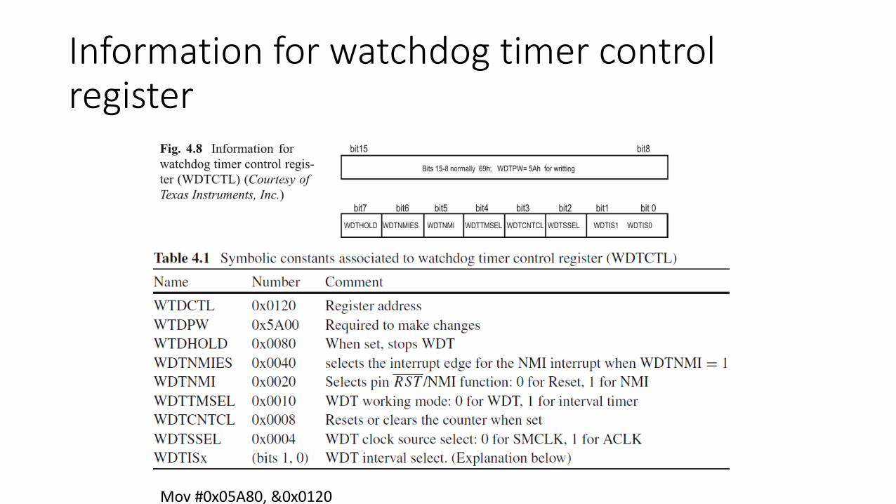
Information for watchdog timer control register
Mov #0x05A80, &0x0120

Information for watchdog timer control register
mov #WDTPW+WDTTMSL+WDTCNTCL+WDTSSEL+WDTIS0,&WDTCTL

Labels
• Entry statement of main code or ISR (Interrupt Service Routine). • Entry statement of subroutine• Instruction to which a reference is made
MOV.W #Mainloop, R6 ; R6=F80EHMOV.W Mainloop, R6 ; R6=E3D2HCALL #Mainloop ; CALL A SUB WITH 0XF80EH

Reset vector Allocation
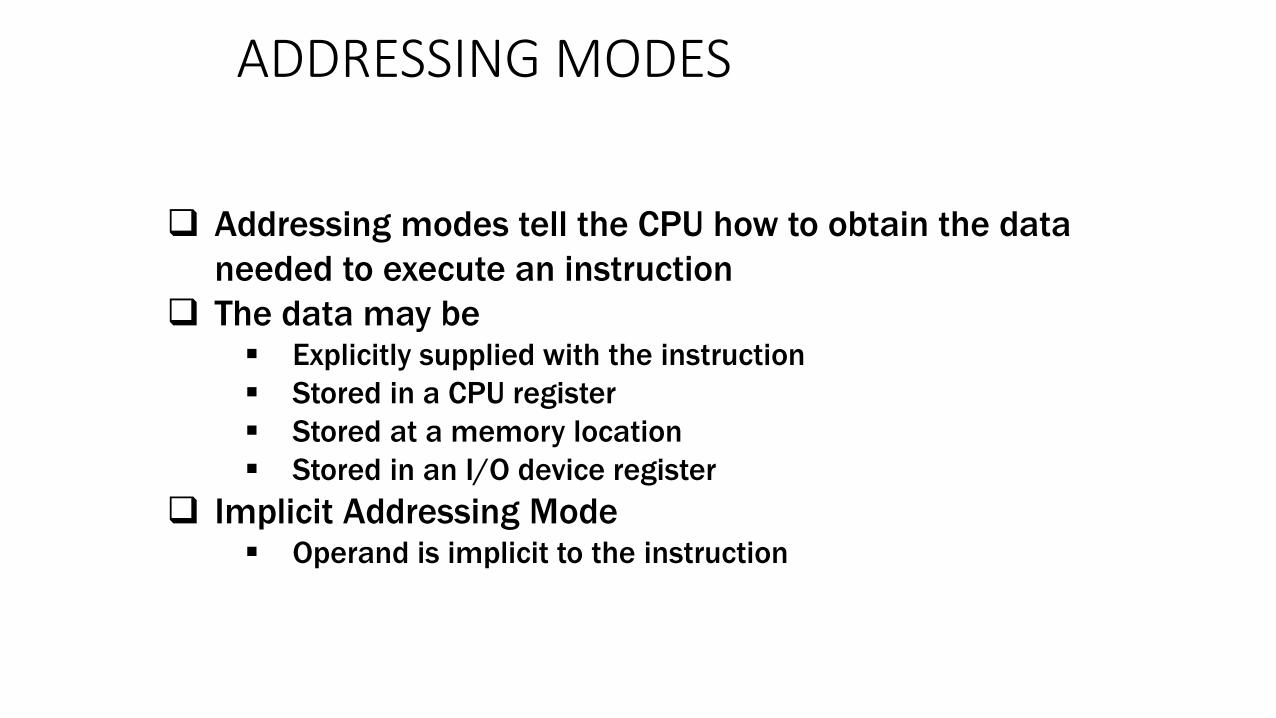
ADDRESSING MODES
39
Addressing modes tell the CPU how to obtain the data
needed to execute an instruction
The data may be Explicitly supplied with the instruction
Stored in a CPU register
Stored at a memory location
Stored in an I/O device register
Implicit Addressing Mode Operand is implicit to the instruction

ADDRESSING MODES
Copyright 2009 Texas Instruments All Rights Reserved 40
Immediate Addressing Mode Syntax: #Number
Register Addressing Mode Syntax: Rn
Indexed Addressing Mode Syntax: X(Rn)
Absolute or Direct Mode Syntax: &X address is X
Indirect Register Mode Syntax: @Rn
Direct Mode X -> address is X

ISA 41
Addressing Modes
Addressing Modes
Address Mode As/*Ad Registers SyntaxRegister *00 R0-R2, R4-R15 Rn
*00 R3 #0Symbolic *01 R0 addressIndexed Register *01 R1, R4-R15 index(Rn)Absolute *01 R2 &address
01 R3 #1Register Indirect 10 R0-R1,R4-R15 @Rn
10 R2 #410 R3 #2
Immediate 11 R0 #numberIndirect auto-inc 11 R1,R4-R15 @Rn+
11 R2 #811 R3 #-1
15 14 13 12 11 10 9 8 7 6 5 4 3 2 1 0
Opcode S-reg Ad b/w As D-reg

42
Copyright 2009 Texas Instruments All Rights Reserved
Addressing Modes
• The locations are specified using various addressing modes. There are seven of thesein all but we look at only some of them.
• A single character denotes the mode in the operand.• immediate, #: The value itself (word or byte) is given and stored in the word following the
instruction. This is also known as a literal value.
• absolute, &: The address of a label in memory space is given and stored in the word following theinstruction.
• @ The address of a register in memory space is given and stored in the word following theinstruction.
• register, R: This specifies one of the 16 registers in the CPU.

43
Immediatemov.b #00001000b,&0x0029 ; LED2 (P2.4) on ,
; LED1 (P2.3) off
• A byte with immediate value (#) 00001000b is copied to the register at address (&)0x0029.
• check the memory map you can confirm that this is the port P2 output registerP2OUT.
• Fortunately the assembler allows us to use symbolic constants as in C, which aremuch clearer to understand. It substitutes their values from the header file:
mov.b #00001000b,& P2OUT ; LED2 (P2.4) on , LED1 (P2.3) off
• The header file includes a set of constants such as BIT3, which could be usedinstead of 00001000b.

Memory
0x0000
0xFFFFISA 44
Addressing Modes
Registers
CPU
ADDER
11 w/R0 = Immediate Mode
add.w #100,r10 ;r10 = 100 + r10
PCPCPC
R10
IR0x503a
PC0x503a
0x0064
ALU
+2+2
BYU CS 224
opcode S-reg Ad b/w As D-reg
0 1 0 1 0 0 0 0 0 0 1 1 1 0 1 0
0 0 0 0 0 0 0 0 0 1 1 0 0 1 0 0
2 Cycle Instruction

Register Addressing Mode
• mov.w R5 ,R6 ; move (copy) word from R5 to R6
• The PC is incremented by 2 while the instruction is being fetched, before it is used as a source.
• As = 00
Memory
0x0000
0xFFFFISA 46
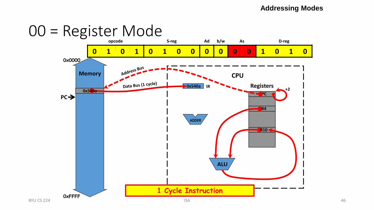
00 = Register Mode
Addressing Modes
Registers
CPU
ADDER
add.w r4,r10 ;r10 = r4 + r10
PCPC
R10
R4
IR0x540a0x540a
PC
ALU
+2
BYU CS 224
opcode S-reg Ad b/w As D-reg
0 1 0 1 0 1 0 0 0 0 0 0 1 0 1 0
1 Cycle Instruction
Indexed Mode
• mov.b 3(R5),R6 ; load byte from address 3+(R5) into R6
• Indexed addressing can be used for the source, destination, orboth
• R5 is used for the index here
• As = 01

Memory
0x0000
0xFFFFISA 48
01 = Indexed Mode
Addressing Modes
Registers
CPU
ADDER
add.w 6(r4),r10 ;r10 = M(r4+6) + r10
0x0006PCPCPC
R10
R4
IR0x541a0x541a
PC
ALU
+2+2
BYU CS 224
opcode S-reg Ad b/w As D-reg
0 1 0 1 0 1 0 0 0 0 0 1 1 0 1 0
0 0 0 0 0 0 0 0 0 0 0 0 0 1 1 0
3 Cycle Instruction

Memory
0x0000
0xFFFFISA 50
Addressing Modes
Registers
CPU
ADDER
cnt
01 w/R2 = Absolute Mode
0000
add.w &cnt,r10 ;r10 = M(cnt) + r10
0xc018PCPCPC
R10
IR0x521a0x521a
PC
ALU
+2+2
BYU CS 224
opcode S-reg Ad b/w As D-reg
0 1 0 1 0 0 1 0 0 0 0 1 1 0 1 0
1 1 0 0 0 0 0 0 0 0 0 1 1 0 0 0
3 Cycle Instruction

Indirect Register Mode
• mov.w @R5 ,R6 ; load word from address (R5)=4 into R6• The address of the source is 4, the value in R5. Thus a word is loaded from
address 4 into R6. The value in R5 is unchanged.
• Indirect addressing cannot be used for the destination so indexed addressing must be used
• mov.w R6 ,0( R5) ; store word from R6 into address 0+(R5)=4

Memory
0x0000
0xFFFFISA 52
10 = Indirect Register Mode
Addressing Modes
Registers
CPU
ADDER
add.w @r4,r10 ;r10 = M(r4) + r10
PCPC
R10
R4
IR0x542a0x542a
PC
ALU
+2
BYU CS 224
opcode S-reg Ad b/w As D-reg
0 1 0 1 0 1 0 0 0 0 1 0 1 0 1 0
2 Cycle Instruction
Indirect Autoincrement
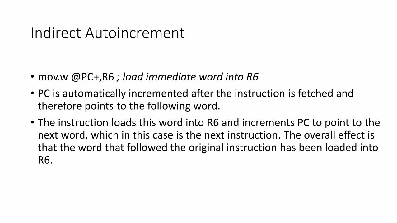
• mov.w @PC+,R6 ; load immediate word into R6
• PC is automatically incremented after the instruction is fetched andtherefore points to the following word.
• The instruction loads this word into R6 and increments PC to point to thenext word, which in this case is the next instruction. The overall effect is that the word that followed the original instruction has been loaded intoR6.
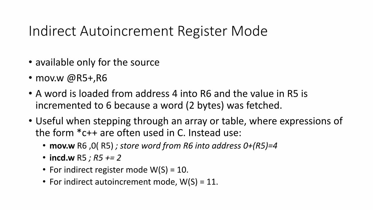
Indirect Autoincrement Register Mode
• available only for the source
• mov.w @R5+,R6
• A word is loaded from address 4 into R6 and the value in R5 is incremented to 6 because a word (2 bytes) was fetched.
• Useful when stepping through an array or table, where expressions of the form *c++ are often used in C. Instead use:
• mov.w R6 ,0( R5) ; store word from R6 into address 0+(R5)=4
• incd.w R5 ; R5 += 2
• For indirect register mode W(S) = 10.
• For indirect autoincrement mode, W(S) = 11.
Memory
0x0000
0xFFFFISA 55
Addressing Modes
Registers
CPU
ADDER
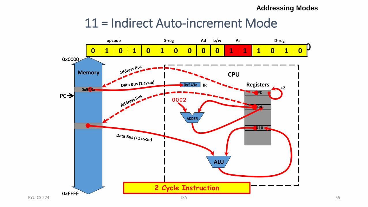
11 = Indirect Auto-increment Mode
add.w @r4+,r10 ;r10 = M(r4+) + r10
PCPC
R10
R4
IR0x543a
PC0x543a
0002
ALU
+2
BYU CS 224
opcode S-reg Ad b/w As D-reg
0 1 0 1 0 1 0 0 0 0 1 1 1 0 1 0
2 Cycle Instruction
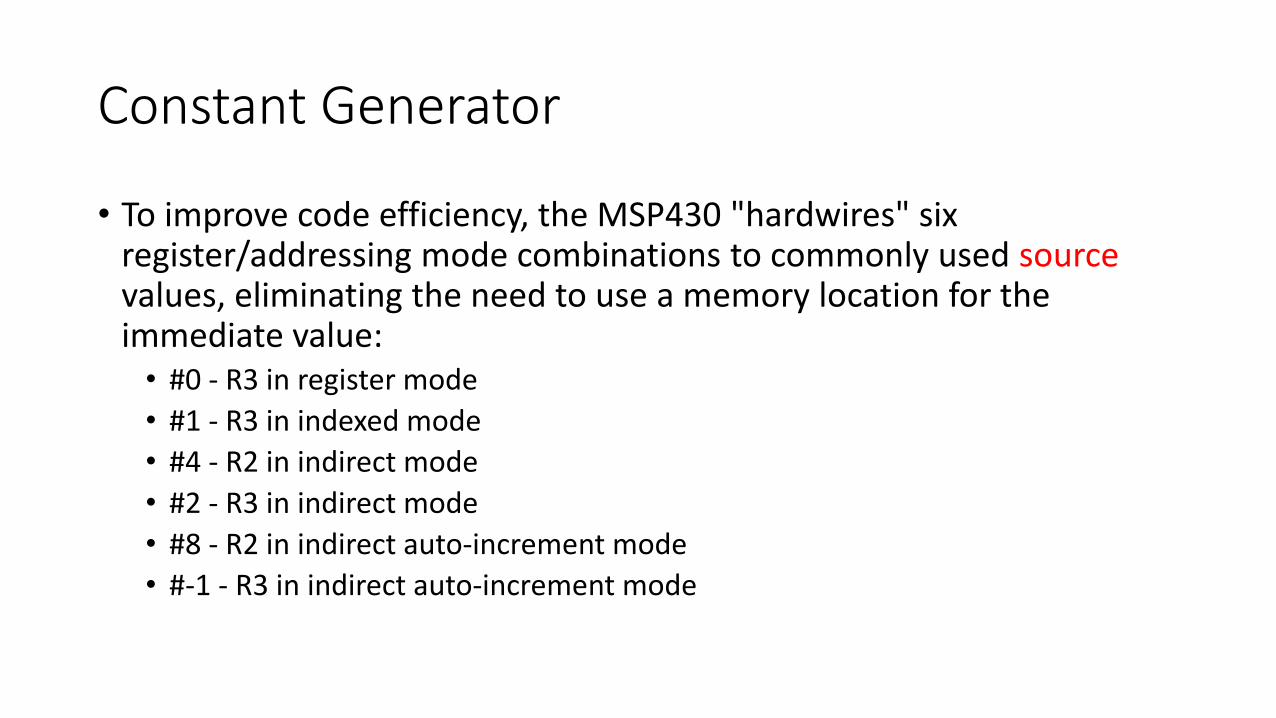
Constant Generator
• To improve code efficiency, the MSP430 "hardwires" six register/addressing mode combinations to commonly used sourcevalues, eliminating the need to use a memory location for the immediate value:
• #0 - R3 in register mode
• #1 - R3 in indexed mode
• #4 - R2 in indirect mode
• #2 - R3 in indirect mode
• #8 - R2 in indirect auto-increment mode
• #-1 - R3 in indirect auto-increment mode

Memory
0x0000
0xFFFFISA 57
Addressing Modes
Registers
CPU
ADDER
Constant Generator
add.w #1,r10 ;r10 = #1 + r10
PCPC
R10
0000
0001
0002
0004
0008
ffff
IR0x531a
PC0x531a
ALU
+2
BYU CS 224
opcode S-reg Ad b/w As D-reg
0 1 0 1 0 0 1 1 0 0 0 1 1 0 1 0
1 Cycle Instruction

Addressing Modes (C, C++)
C, C++ Addressing Mode Assembly
int a, b, tab[100];
a = tab[b];
Indexed Register mov.w tab(r4),r5
int* cow = &tab[0];
int cat = *cow;
Indirect Register mov.w @r6,r5
int* cow = &tab[0];
int cat = *cow++;
Indirect Auto-increment mov.w @r6+,r5
int cat = 100; Immediate mov.w #100,r5
int cat = *(int*)100; Absolute mov.w &100,r5
extern int dog;
int cat = dog;
Symbolic mov.w dog,r5
register int x, y;
y = x;
Register mov.w r4,r5
BYU CS 224 ISA 58

ADDRESSING MODE EXAMPLES
Copyright 2009 Texas Instruments All Rights Reserved 59

ADDRESSING MODE EXAMPLES
Copyright 2009 Texas Instruments All Rights Reserved 60

Addressing Modes (C, C++)
C, C++ Addressing Mode Assembly
int a, b, tab[100];
a = tab[b];
Indexed Register mov.w tab(r4),r5
int* cow = &tab[0];
int cat = *cow;
Indirect Register mov.w @r6,r5
int* cow = &tab[0];
int cat = *cow++;
Indirect Auto-increment mov.w @r6+,r5
int cat = 100; Immediate mov.w #100,r5
int cat = *(int*)100; Absolute mov.w &100,r5
extern int dog;
int cat = dog;
Symbolic mov.w dog,r5
register int x, y;
y = x;
Register mov.w r4,r5
BYU CS 224 ISA 61

Exercise 3.2
ISA 62BYU CS 224
register int x, y;extern int pig;int cat, dog, table[100];int* cow = &table[0];
y = x;cat = table[dog];cat = *cow;dog = *cow++;cat = 100;cat = *(int*)100;cat = pig;
mov.w @r8,r6mov.w r4,r5mov.w #100,r6mov.w table(r7),r6mov.w @r8+,r7mov.w pig,r6mov.w &100,r6
Match the C code on the left with the possible assembly code in the middle and the addressing mode on the right.
1.
2.
3.
4.
5.
6.
7.
a.
b.
c.
d.
e.
f.
g.
Absolute
Indexed register
Indirect auto-inc
Indirect register
Immediate
Register
Symbolic
i.
ii.
iii.
iv.
v.
vi.
vii.

Core instructions
63

Core instructions
64

65
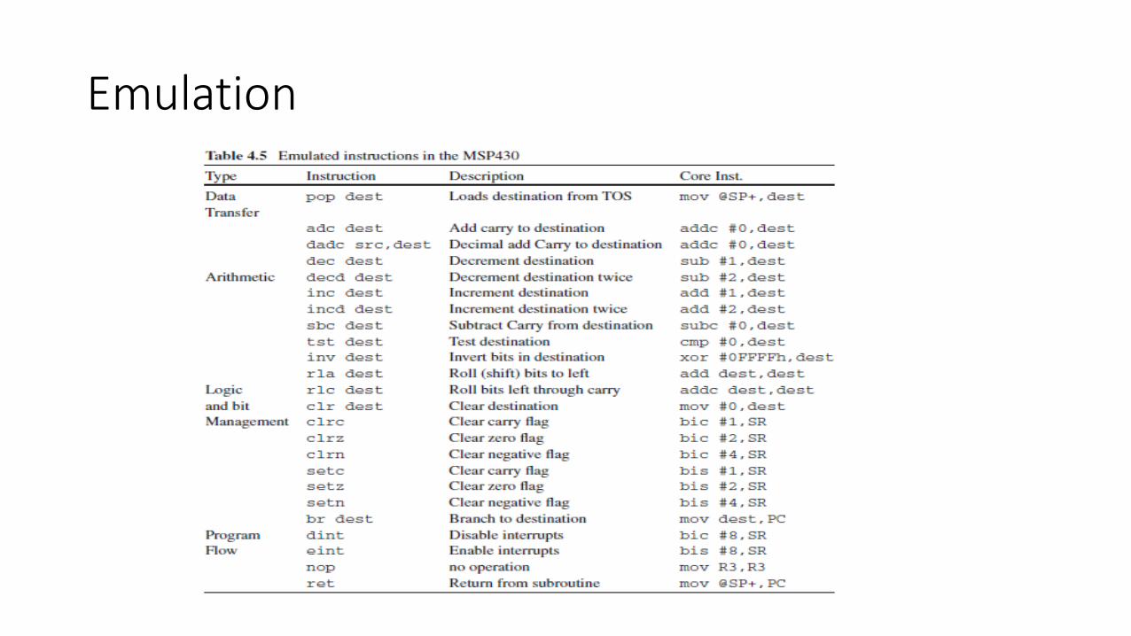
Emulation
• The clear instruction clr.w or clr.b puts the value of the destination to 0. Inmany processors this is a distinct instruction but not in the MSP430: Theassembler translates clr.b P2OUT to mov.b #0,P2OUT. You can see this in theDisassembly window of the debugger. This is an example of an emulatedinstruction.
• The program in assembly language writes to P2OUT before P2DIR, theopposite order from the program in C. This ensures that the correct valuesappear on the pins as soon as they are made into outputs.
• If the pins are switched to output first, the outputs initially are driven to the values that happen to be sitting in P2OUT
• It is perfectly legal to write to P2OUT while the pin is configured as an input: The value waits in a buffer until the pins are enabled for output.
66
Emulation

Word and Byte Instructions
67
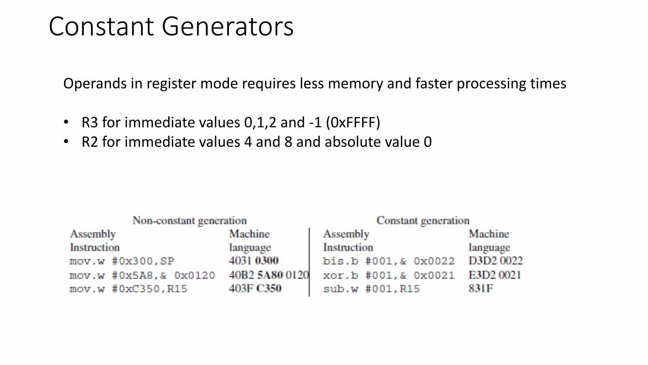
Constant Generators
68
Operands in register mode requires less memory and faster processing times
• R3 for immediate values 0,1,2 and -1 (0xFFFF)• R2 for immediate values 4 and 8 and absolute value 0

Types of Instructions
Copyright 2009 Texas Instruments All Rights Reserved 69
Data Transfer Instructions Copy data from a source to a destination
Arithmetic-logic Instructions Perform arithmetic and/or logic operations on operands
Program Control Instructions Modify the default flow of execution in a program


Data Transfer Instructions
Copyright 2009 Texas Instruments All Rights Reserved 71
Copy data from a source to a destination destination ← source
Do not affect flags
Included Instructions: Data transfer: MOVE
Data exchange: SWAP
Stack manipulation: PUSH & POP
Treat I/O locations like memory Memory-mapped I/O
Examples:
MOV R8,R3 ; Copies the contents of R8 into R3
MOV (0xF348),R5 ; Copies into R5 the word at address F348h
PUSH R7 ; Copies onto the top of the stack the contents of R7

Arithmetic Logic Ops
Copyright 2009 Texas Instruments All Rights Reserved 72
Perform arithmetic and/or logic operations on data destination ← (DestinationOperand SourceOperand)
Flags affected according to operation result
Included Instructions: Arithmetic: ADD, SUB
Compare and test: CMP, TEST
Bitwise logic: AND, OR, XOR, NOT
Bit Displacement: SHIFT, ROTATE
Examples:
ADD R7,R5 ; Places on R5 the sum of the contents of R5 and R7
AND #05AD,R6 ; Places on R6 the bitwise result of anding the contents of R6 and the value 05ADh
ROTL R3 ; Rotates the contents of register R3 one position to the left

Arithmetic Logic Ops

Arithmetic Logic Ops

Working with Bits
Copyright 2009 Texas Instruments All Rights Reserved 75
Bitwise operations work directly on bits

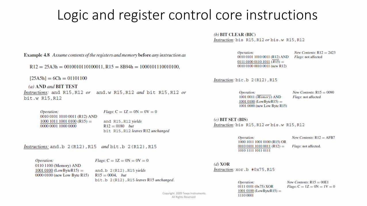
Logic and register control core instructions
Copyright 2009 Texas Instruments All Rights Reserved 76
Logic and register control core instructions
Copyright 2009 Texas Instruments All Rights Reserved 77

Logic and register control core instructions
78

Logic and register control core instructions
79

PROGRAM CONTROL INSTR.
Copyright 2009 Texas Instruments All Rights Reserved 80
Modify the default flow of execution in a program PC ← NewAddress
Do not affect flags
Included Instructions: Unconditional Jump: Always change the PC
Conditional Jump: Change the PC if condition is true
Subroutine Calls and Returns: Transfer control from main to subroutines,
returning to the calling point
Examples:
JMP #F345h ; Loads PC with the address 0xF345 so program execution continues there
JZ #F345 ; Loads PC with the address 0xF345 if the Zero Flag is set
CALL Sub1 ; Saves PC onto the stack and loads PC with address Sub1. When special instruction
RET

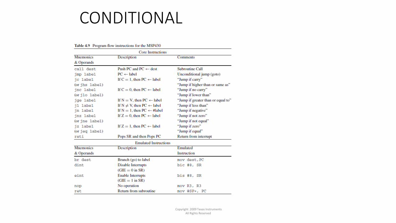
CONDITIONAL
Copyright 2009 Texas Instruments All Rights Reserved 81
Conditional Jump Instructions enable decision making in programs
CONDITIONAL
Copyright 2009 Texas Instruments All Rights Reserved 82

CONDITIONAL
83

LOOP
84
Correspondence between some flowcharts constructs and register transfer notation (RTN)

LOOP
Copyright 2009 Texas Instruments All Rights Reserved 85

LOOP
86
STACK
Copyright 2009 Texas Instruments All Rights Reserved 87
• A portion of memory used to temporarily store data
• Access through special register Stack Pointer (SP)
• Last-in-First-out (LIFO) operation
• Stack contents is volatile
• Stack Operations
• PUSH: Places data on top of the stack
• POP (or pull) : Retrieves data from the top of the stack
• Other instructions and events modifying the stack
• Invoking and returning from a subroutine call
• Responding and returning from an interrupt event

STACK
Copyright 2009 Texas Instruments All Rights Reserved 88

STACK
89

STACK
Copyright 2009 Texas Instruments All Rights Reserved 90
• Push • Update the stack pointer to point to the new TOS • Copy the operand to the new TOS
• Pop or Pull • Copy the contents in the actual TOS to the destination • Update the stack pointer to point to the new TOS • Example: PUSH R9 and POP R9 (assume SP = 027Eh)


SUBROUTINE
Copyright 2009 Texas Instruments All Rights Reserved 92
1.Function Call
Saves PC onto stack
2.Function Execution
PC loaded with function address
3.Executing the Return
Restore the PC from the stack
4.Back at Main Program
Continue at instruction after “CALL”
![Advantages of PIC - Hacettepe Universityalkar/ELE414/dirz2005/wpic[2005]print.pdf · 1 Week 13 An Introduction to PIC microcontrollers Advantages of PIC • It is a RISC (Reduced](https://static.fdocuments.us/doc/165x107/5a6fd6507f8b9a93538b6f43/advantages-of-pic-hacettepe-universitywwweehacettepeedutralkarele414dirz2005wpic2005printpdfpdf.jpg)


![I/O PROGRAMMING - Hacettepe Universityalkar/ELE336/w9-hacettepe[2016].pdf · • Diagram the design of peripheral I/O using the ... • Describe the purpose of a simple programmable](https://static.fdocuments.us/doc/165x107/5aa702a27f8b9a424f8bc758/io-programming-hacettepe-alkarele336w9-hacettepe2016pdf-diagram-the-design.jpg)


