Wednesday, November 16, 2016 Plymouth Meeting, PA … Seminar/Breakfast Seminar nov16.pdf ·...
70
Cutting Edge Masonry Codes & Standards Delaware Valley Association of Structural Engineers Wednesday, November 16, 2016 n Plymouth Meeting, PA Copyright 2016 IMI all rights reserved 1 Scott W. Walkowicz, PE , N.C.E.E.S . Walkowicz Consulting Engineers on behalf of the Delaware Valley & New Jersey Structural Coalitions New Jersey Bricklayers and Allied Craftworkers Labor Management Fund
Transcript of Wednesday, November 16, 2016 Plymouth Meeting, PA … Seminar/Breakfast Seminar nov16.pdf ·...

Cutting Edge
Masonry Codes & Standards
Delaware Valley Association
of Structural Engineers
Wednesday, November 16, 2016 n Plymouth Meeting, PA
Copyright 2016 IMI all rights reserved 1
Scott W. Walkowicz, PE, N.C.E.E.S.Walkowicz Consulting Engineers
on behalf of the Delaware Valley & New Jersey Structural Coalitions
New Jersey Bricklayers and Allied Craftworkers
Labor Management Fund

2
International Masonry Institute
Market Development &
Technical Services
Technical Assistance
Drawing & Specification Review
Jobsite Troubleshooting
Structural Masonry Support
Research & Development
Masonry Detailing Series
Codes & Sandards
Software & Design Tools

3
International Masonry Training
and Education Foundation
Apprenticeship & Journey Level
Training
Brick & Block
Restoration
Tile Setting & Finishing
Terrazzo
Cement Finishing
Refractory
Marble Setting
Stone
Rainscreen Installation

This presentation is protected by US and International copyright laws. Reproduction,
distribution, display and use of the presentation without written permission of
the speaker is prohibited.
© International Masonry Institute 2016 All Rights Reserved
Copyright Materials
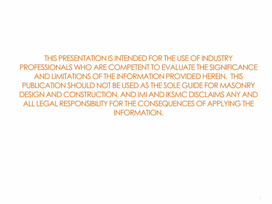
THIS PRESENTATION IS INTENDED FOR THE USE OF INDUSTRY
PROFESSIONALS WHO ARE COMPETENT TO EVALUATE THE SIGNIFICANCE
AND LIMITATIONS OF THE INFORMATION PROVIDED HEREIN. THIS
PUBLICATION SHOULD NOT BE USED AS THE SOLE GUIDE FOR MASONRY DESIGN AND CONSTRUCTION, AND IMI AND IKSMC DISCLAIMS ANY AND
ALL LEGAL RESPONSIBILITY FOR THE CONSEQUENCES OF APPLYING THE
INFORMATION.
5

Learning Objectives
Describe the development process of the TMS 402 Building Code Requirements & TMS 602 Specification for Masonry Structures.
Understand the relationship between the IBC and the TMS 402/602.
Review and understand select changes incorporated into the 2011, 2013, and 2016 TMS 402/602 and discuss the likely impact from these changes to masonry design & construction.
Understand how to implement the new provisions to produce cutting edge masonry designs.
6

MSJC & TMS 402/602
DEVELOPMENT PROCESS

ICC, IBC, IRCICC - International Code Council (I-Codes)
3 year development cycle
Multiple materials
Structural, fire, etc.
IBC - International Building Code
Chapter 14 Veneer
Chapter 17 Special Inspection
Chapter 21 Masonry
IRC – International Residential Code
1 and 2 family dwellings
8

TMS 402-11 /ACI 530-11 /ASCE 5-11 (MSJC)
TMS 402-13 /ACI 530-13 /ASCE 5-13 (MSJC)
TMS 402-16 (TMS 402)
Building Code Requirements for Masonry Structures
TMS 602-11 /ACI 530.1-11/ASCE 6-11 (MSJC)
TMS 602-13 /ACI 530.1-13/ASCE 6-13 (MSJC)
TMS 602-16 (TMS 602)
Specification for Masonry Structures
Commentary for each
Non-mandatory
TMS 402/602 (MSJC) Documents
9

TMS 402/TMS602 (MSJC)
TMS 402 Code contains primarily structural design provisions but also a few Construction Requirements –Designer oriented
Construction provisions are primarily found in the TMS 602
Specification –Contractor & Inspector oriented
Companion Commentary to each – Non-mandatory
10

Mandatory language standards that provide
minimum requirements for the design & construction
of masonry
Typically 3-year development cycle BUT changing to
6 year cycle for the TMS 402/602!
Consensus process
balance, letter ballots, resolution of negatives,
public comment
Sponsoring society oversight & approval
TMS, ACI, SEI/ASCE
TMS is sole sponsor for 2016 edition! TMS 402/602
Intended for adoption by Codes
TMS 402/602 (MSJC) Development
11

IBC: Model code,
legally adopted with or
without local
amendments
MSJC & TMS 402/602:
Reference documents
How do they relate?
12

Check the dates
MSJC & TMS 402/602 date will be one or two years PRIOR to its companion IBC
’12 IBC goes with ’11 MSJC
‘15 IBC goes with ‘13 MSJC
Also check for local amendments & adoptions
Companion Documents
2011
2013
13

QUICK REVIEW
SELECT CHANGES – 2011 MSJC

15
2011 MSJC – Select Changes
The Code &
Commentary and
the Specification &
Commentary are
now shown in a
side by side format
for easier use by
users

16
2011 MSJC – Select Changes
Updated to ASCE 7-10
Required major recalibration
as a result of the change by
ASCE 7 to base wind loads
on a “strength” level versus a
service level. As a result,
wind “triggers” changed for:
Empirical Design
Veneer
Glass Unit Masonry

17
2011 MSJC – Select Changes
Recalibration of stresses Removal of 1/3 stress increase option that was
formerly permitted for Allowable Stress Design
(ASD) when considering wind or seismic loads
Harmonization of ASD and SD shear provisions
Some Allowable Stresses increased. Reduces
impact of removal of 1/3 stress increase options
Conflict between the MSJC ASD loading
provisions permitting the 1/3 stress increase and
the ASCE 7-05 prohibition of the 1/3 stress
increase has been eliminated.
1/3 Stress Increase for
Wind & Seismic

18
Allowable Stresses - General
Anchor Bolts: No change
Major Revision in 2008
2008 Increased Allowables; Harmonized
with Strength Design
Bearing Stress
Increased from 0.25 f′m to 0.33 f′m Nominal strength also increased from
0.60 f′m to 0.80 f′m Changes based on comparison with other
codes

19
Allowable Stresses – Unreinforced Masonry
Flexural tension
Increased by 33% based on reliability analysis
Unchanged
Axial compression
Combined flexural and axial compression
(0.33 f′m)
Shear
Flexural tension usually controls with
unreinforced masonry so impact of
unchanged allowable stresses is minimal

20
Allowable Stresses – Reinforced Masonry
Allowable stresses for axial compression not changed
Allowable steel reinforcement stress increased to
32 ksi (Grade 60 steel)
Based on comparison to strength design
Allowable masonry stress due to combined flexure
and axial loads increased to 0.45f’m
Based on comparison to strength design
Shear strength provisions now similar to strength
design
Based on comparison to experimental data
Permitted to add masonry &steel shear strength

21
Impact of ASD Shear Design Provisions
2011 ASD shear provisions require
approximately the same amount of
reinforcement as strength design provisions
2011 ASD shear provisions require
significantly less reinforcement than the
2008 ASD provisions for ordinary shear walls
2011 ASD shear provisions require
approximately the same amount of
reinforcement as the 2008 ASD provisions
for special shear walls

22
Example of the Benefits
Building perimeter: 2(350’) + 2(525’) = 1,750 LF of wall
2009 IBC / TMS 402: #5 Rebar at 24” o.c. =
875 rebar = 19,250 LF + lap splices
124 CY of grout
2012 IBC / TMS 402: #5 Rebar at 32” o.c. =
657 rebar = 14,438 LF + lap splices
25% reduction / 2009 code = 33% increase!
4,812 LF less
5,053 lbs. less
93 CY of grout
25% reduction using new codes / 33% increase using the
2009 code
31 CY less = 4 to 5 trucks!

23
2011 MSJC – Select Changes
The beneficial effect of larger cover for
computation of development length has been
changed from 5db to 9db
Option: Lap splices are permitted to be reduced
where transverse reinforcement is placed within
8” of the end of the splice if it is fully developed
in grouted masonry.
2 Updates - Lap Splices & Development Length
m
yb
dfK
fdl
'
13.02

2011 MSJC – Select Changes
Deep Beam Provisions
added. Apply to beams
where the effective
span-to-depth ratio,
leff /dv is less than:
3 for continuous span
2 for simple span
Requires additional analysis as well as
minimum flexural and shear reinforcement
(Code Section 1.13.2)
leff per 1.13.1
dv
24

25
2011 MSJC – Select Changes
New Appendix B for Masonry Infill
Unreinforced CMU and Clay units (work on
AAC infill on the 2013 agenda)
Participating and non-participating infill
Prescriptive reinforcement required

New in the 2011 MSJC
Anchor bolt
installation
requirements have
been revised.
Reference only to
running bond or “not
in running bond”
rather than reference
to stack bond or other
bond patterns.

New in the 2011 MSJC
Revised equation for walls
with laterally restrained or
laterally unrestrained
unbounded prestresssing
tendons.
Commentary guidance on
seismic design coeffients for
prestressed masonry shear
walls. (Will be removed
when included in ASCE 7)

2011 MSJC – Select Changes
Empirical design restricted from use in structures located in Risk Category IV. (Essential Structures)
Adhered dimension stone provisions are included.
Single pintle ties are permitted for anchored veneer
Clarification that drips are not permitted in wire anchors and joint reinforcement cross wires and tabs.
28

2011 MSJC – Select Changes
AAC moves from an Appendix A to new Chapter 8
Provisions for nominal sliding shear strength added at the interface of AAC and thin bed mortar.
Quality assurance requirements for AAC masonry were expanded and clarified.
29

2011 MSJC – Select Changes
MSJC QA tables Direct reference in the IBC 2012
New column in the Tables includes reference to specific code/spec provisions
30

2011 MSJC – Select Changes
Grout lift height changed to 5’-4” to accommodate modular construction.
Prism testing provisions for specimens
cut from construction were included.
31

and many more…
2011 MSJC Select Changes
32

SELECT CHANGES –
2013 MSJC
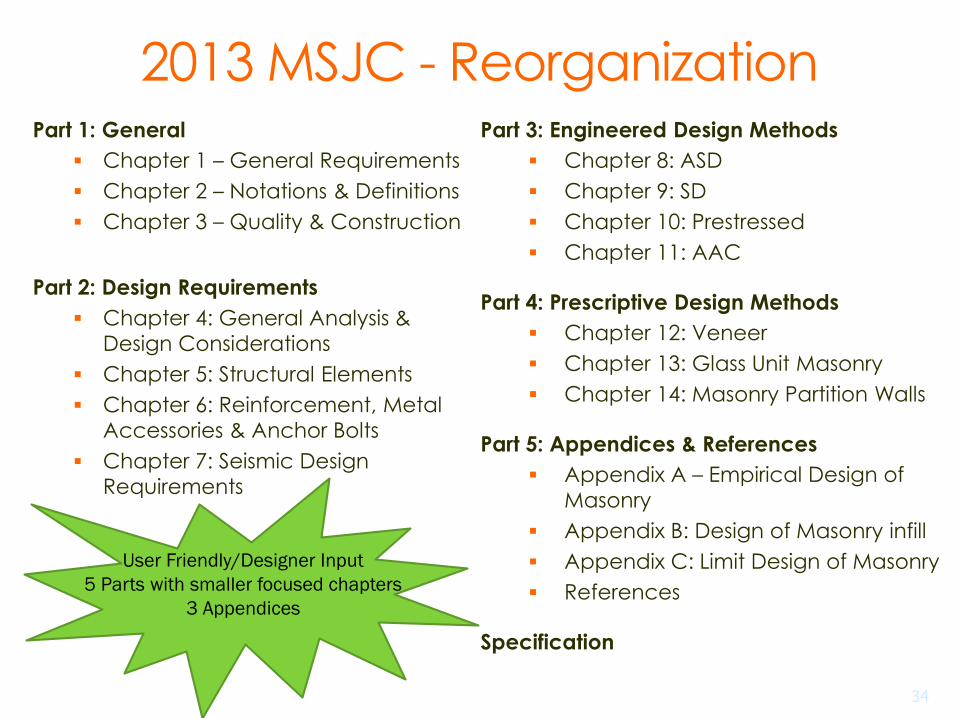
2013 MSJC - ReorganizationPart 1: General
Chapter 1 – General Requirements
Chapter 2 – Notations & Definitions
Chapter 3 – Quality & Construction
Part 2: Design Requirements
Chapter 4: General Analysis &
Design Considerations
Chapter 5: Structural Elements
Chapter 6: Reinforcement, Metal
Accessories & Anchor Bolts
Chapter 7: Seismic Design
Requirements
Part 3: Engineered Design Methods
Chapter 8: ASD
Chapter 9: SD
Chapter 10: Prestressed
Chapter 11: AAC
Part 4: Prescriptive Design Methods
Chapter 12: Veneer
Chapter 13: Glass Unit Masonry
Chapter 14: Masonry Partition Walls
Part 5: Appendices & References
Appendix A – Empirical Design of
Masonry
Appendix B: Design of Masonry infill
Appendix C: Limit Design of Masonry
References
Specification
User Friendly/Designer Input
5 Parts with smaller focused chapters
3 Appendices
34

2013 MSJC Code Reorganized
Part 1: General
Chapter 1 –General
Requirements
Chapter 2 –Notations & Definitions
Chapter 3 –Quality &
Construction
Part 2: Design Requirements
Chapter 4: General Analysis
& Design Considerations
Chapter 5: Structural Elements
Chapter 6: Reinforcement,
Metal Accessories & Anchor Bolts
Chapter 7: Seismic Design Requirements
Part 3: Engineered
Design Methods
Chapter 8: ASD
Chapter 9: SD
Chapter 10: Prestressed
Chapter 11: AAC
Part 4: Prescriptive
Design Methods
Chapter 12: Veneer
Chapter 13: Glass Unit Masonry
Chapter 14: Masonry Partition
Walls
Part 5: Appendices &
References
Appendix A –Empirical Design
of Masonry
Appendix B: Design of Masonry
infill
Appendix C: Limit Design of Masonry
References
35

2013 MSJC - Limit Design
Appendix C in 2013 MSJC
Seismic design – Optional
Sophisticated Analysis Method
Perforated Walls
“This was a bold move for masonry and marks it as an even more serious structural material.”
36

37
Limit Design: Seismic Design of
Reinforced Masonry Structures
force - based design (ASCE 7 - 10)
emphasizes strength
displacement - based design (no code provisions yet)
emphasizes deformation

Force-based Seismic Design Limitations
uncoupled cantilever walls are
easy to design
coupled cantilever walls are
more difficult to design
walls with arbitrary openings
may be impossible to design
rationally
38

2013 MSJC - Empirical design
Past MSJC Codes
Chapter 5: Empirical Design of Masonry
2013 MSJC Code
Appendix A: Empirical Design of Masonry
Relocated from previous Code Chapter 5
Mandatory appendix
Checklist to make sure provisions are used
correctly and appropriately.
39

2013 MSJC – Partition walls
Chapter 5 14: Masonry Partition Walls
Partition walls are ‘walls without structural function’
New requirements are similar to the partition wall requirements in previous empirical chapter but changes based on ASD analysis
Tables for 5 psf and 10 psf lateral load
Example – 5 psf table shown below
Unit and Masonry Type Mortar types
Portland cement/lime or mortar
cement
Masonry cement or air entrained
portland cement/lime
M or S N M or S N
Ungrouted and partially grouted hollow units 26 24 22 18
Solid units and fully grouted hollow units3 40 36 33 26
Maximum l/t1 and h/t1 Requirements from 2013 MSJC Table 14.3.1(5) when the Lateral Load does not exceed 5 psf (0.239 kPa)
1 t by definition is the nominal thickness of member
40

2013 MSJC - Select Changes
Partially grouted shear walls were addressed with some refinement perhaps coming in future cycles.
Moment magnifier provisions were added for concrete masonry, clay masonry and also for AAC masonry.
Modulus of Rupture values were increased by approximately 33%
41

2013 MSJC - Select Changes
Masonry Cement Mortar permitted for
fully grouted participating elements in
SDC D and higher
AAC Infill provisions were added to
Appendix B: Design of Masonry Infill
42

2013 MSJC – Select Changes
Updating done for the requirements for:
mechanical splices in flexural reinforcement
in plastic hinge zones;
joint reinforcement and seismic clips for
anchored veneer in SDC D, E, and F.
Joint reinforcement can be used as
primary reinforcement in Strength Design.
43

2013 MSJC – Unit Strength Table
Net area compressive strength of concrete masonry, psi
(MPa)
Net area compressive strength of ASTM C90 concrete masonry units, psi (MPa)
Type M or S Mortar Type N Mortar
1,700 (11.72) --- 1,900 (13.10)
1,900 (13.10) 1,900(13.10) 2,350 (14.82)
2,000 (13.79) 2,000 (13.79) 2,650 (18.27)
2,250 (15.51) 2,600 (17.93) 3,400 (23.44)
2,500 (17.24) 3,250 (22.41) 4,350 (28.96)
2,750 (18.96) 3,900 (26,89) ----
3,000 (20.69) 4,500 (31.03) ----
2013 MSJC Table 2: Compressive strength of masonry based on the compressive strength of concrete masonry units and type of mortar used in construction
Both unit strength tables reformatted to be more user friendly
Values in Table 2 were recalibrated as shown above
Generally higher masonry compressive strength tailing off at
higher unit strengths
Prism testing still an option
2800
4800
3050
5250
Select pre-2013 values
44
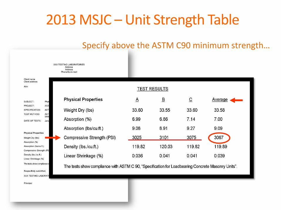
Specify above the ASTM C90 minimum strength…
2013 MSJC – Unit Strength Table

2013 MSJC – ASTM C90 Changes
Changed the web requirements:
C90-11a and earlier:
Minimum thicknesses of ¾” for 3” and 4” units,
1” for 6” and 8”, and 1-1/8” for 10” and greater;
Equivalent Web Thickness values – greater than
2 webs, less than three…
Starting with C90-11b:
Minimum thicknesses of ¾” for all units;
Normalized Web Area values – 6.5 sq. in./sq. ft.
46

Starting with C90-11b – Equivalent web area replaces equivalent web thickness.
2013 MSJC – ASTM C90 Changes

Examples of unit configurations that comply with new AST C90 web area requirements
2013 MSJC – ASTM C90 Changes
NCMA TEK 2-5B

2013 MSJC - Select Changes
ASTM C90-12 referenced in the 2013 MSJC triggering a requirement to check normalized web area:
ASD and SD – Min. normalized web area of 27 in2/ft2
(revised to 25 in2/ft2 in the 2016 TMS 402 Draft) or do a calculated web shear stress check.
Partitions and Empirical – Min. normalized web area of 27 in2/ft2 (revised to 25 in2/ft2 in the 2016 TMS 402 Draft) required unless section is solidly grouted to use prescriptive provisions. This allows the web shear stress check to be avoided.
49

2013 MSJC - Select Changes
d distance figures were added to the Specification to help illustrate tolerances based on d.
Mortar joint tolerances at foundations and at flashings were clarified.
Acceptable range of placement
+2 in. (50.8 mm)-2 in. (50.8 mm)
Specified location
when wall segment exceeds 24 in. (610 mm)
En
d o
f wall
when d ≤ 8 in. (203 mm), tolerance = ½ in. (12.7 mm)
when 8 in. (203 mm) < d ≤ 24 in. (610 mm), tolerance = 1 in. (25.4 mm)
when d > 24 in. (610 mm), tolerance = 1 ¼ in. (31.8 mm)
Specified location 1 in. (25.4 mm)
When wall segment ≤ 24 in. (610 mm)
d
d
d
Reinforcement on one or both faces
50

2013 MSJC - Select Changes
Clarification that bond beams may be
stepped or sloped.
3)(
(2)
1)(
4)((2)
1)(
(5)
Figure SC-1: Sloped and Stepped Bond Beams
Example of sloped bond beam Example of stepped bond beam
51

and many more…
2013 MSJC Select Changes
52

SELECT CHANGES –
2016 TMS 402/TMS 602

2016 TMS 402/TMS 602
Shear-friction and Shear-friction Strength provisions were added to both ASD (Section 8.3.6) and SD (Section 9.3.6.5) Shear transfer across horizontal interfaces in
walls subjected to in-plane loads.
When subjected to in-plane lateral loads, walls that have a low axial compressive load and a low shear-span ratio are vulnerable to shear sliding, which normally occurs at the base.
Function of the roughness at the base.
Separate equations for both ASD and SD but they are coordinated.
54

2016 TMS 402/TMS 602
Reorganization efforts continued with a primary focus on moving common provisions into Chapter 6 - Reinforcement, Metal Accessories and Anchor Bolts.
Splice and development length requirements were consolidated into Chapter 6 and removed from the individual chapters. (No equation changes)
Nominal bar diameter requirement (Bar diameter shall not exceed one-eighth of the nominal member thickness)which applied only to SD in previous editions was moved to Chapter 6. It now applies to ASD and SD.
55

Chapter 14: Masonry Partition Walls
Previously tables for 5 psf and 10 psf lateral load for unreinforced masonry walls were included. Concern expressed for seismic loading
Limited use for designers
New tables added for h/t and l/t lateral loadings from 5 psf to 50 psf Table 14.3.1 for ungrouted or partially grouted
unreinforced walls.
Table 14.3.2 for solidly grouted unreinforced walls.
Some of the restrictions on use were removed.
56
2016 TMS 402/TMS 602

Table 14.3.1 Partition Walls – Ungrouted or Partially Grouted (See Table 14.3.2 for solidly grouted walls)
57
2016 TMS 402/TMS 602
Example: 15 psf load. Partially grouted 8” wall. PCL mortar. Simple support.
h/t = 15 (from table) t = 8” (nominal dimension of an 8”CMU)
Solve for h: h = (15*8”)/12 = 10’ maximum height.
2016 TMS 402/TMS 602
Loads terminology made consistent throughout the document. ‘Allowable stress level loads’ and ‘Strength level loads’ now are used rather than a mix of ‘nominal loads’ ‘service loads’ and more. Both terms are also defined to help with clarity: Load, allowable stress level – Loads resulting from
allowable stress design load combinations.
Load, strength level – Loads resulting from strength design load combinations.
Definitions were added for ‘Beam’, ‘Lintel’, ‘Pilaster’ and ‘Cavity’ as well as modification to the ‘Collar Joint’ and inconsistencies in the use of the terms were eliminated.
58

2016 TMS 402/TMS 602
Tables, instead of written provisions,
were incorporated in several locations
to more clearly explain the
requirements.
Ease of use by the user
Similar to ACI 318-14 formatting
Highlighted underlying confusion in some
cases which is now clarified.
59

2016 TMS 402/TMS 602
This:
60
TABLE 3.1 MINIMUM QUALITY ASSURANCE LEVEL
3.1.1 Level 1 Quality AssuranceThe minimum quality assurance program for masonry in Risk Category I, II, or III structures and designed in accordance with Part 4 or Appendix A shall comply with the Level 1 requirements of TMS 602 Tables 3 and 4.
3.1.2 Level 2 Quality Assurance3.1.2.1 The minimum quality assurance program for masonry in Risk Category IV structures anddesigned in accordance with Chapter 12 or 13 shall comply with the Level 2 requirements of TMS 602 Tables 3 and 4.3.1.2.2 The minimum quality assurance program for masonry in Risk Category I, II, or III structures and designed in accordance with chapters other than those in Part 4 or Appendix A shall comply with theLevel 2 requirements of TMS 602 Tables 3 and 4.
3.1.3 Level 3 Quality AssuranceThe minimum quality assurance program for masonry in Risk Category IV structures and designed in accordance with chapters other than those in Part 4 or Appendix A
shall comply with the Level 3 requirements of TMS 602 Tables 3 and 4.
Not This:
DESIGNED IN ACCORDANCE WITH RISK CATEGORY I,II OR III RISK CATEGORY IV
Part 3 or Appendix B or Appendix C Level 2 Level 3
Part 4 Level 1 Level 2
Appendix A Level 1 Not permitted

2016 TMS 402/TMS 602
This:
61

2016 TMS 402/TMS 602
Anchored Veneer
Distance between inside face of the veneer
and the backing increased from 41/2” to
45/8” before tie analysis is required.
Option to increase that space to 65/8” with
special anchoring provisions….
62

Adjustable anchor with 2 or more W2.8 wires (min.)
Barrel anchor, plate or prong anchor (min sizes required) to back-up with wood, steel or concrete or masonry backing.
Masonry back-up can also use tab anchor with min. of 2 eyes.
Inside face of veneer to end of the adjustable part of anchor –2” max.
2016 TMS 402/TMS 602
63
Anchored Veneer - 65/8” max. space from inside
of veneer to the backing requirements:

2016 TMS 402/TMS 602
Quality Assurance Tables were rewritten
and simplified.
Duplicate tables were deleted from the TMS 402
Code which now refers to the TMS 602 Tables.
Components of the change:
List current Inspection Requirement tasks for all
levels into a single table.
Segregate Minimum Test Requirements from the
Inspection Requirements.
Changed QA Levels A, B, C to QA Levels 1,2,3.
(Consistent with IBC)
64

2016 TMS 402/TMS 602
Quality Assurance Tables
65Excerpt of Table 4 only

and many more…
66
2016 TMS 402/TMS 602

IN CONCLUSION….

Code Adoption Time Lines -2011 & 2013 MSJC and 2016 TMS 402/602
2011MSJC Referenced in the 2012 IBC and IRC
2013 MSJC Referenced in the 2015 IBC and IRC
2016 TMS 402/ TMS 602 Completed and
Referenced in the 2018 IBC and IRC.
2022 TMS 402/TMS 602 - A six year cycle! Work started Sept. 2016 for reference in the 2024 IBC
Check for local adoption status and
potential local amendments
68

Questions ?
Contacting IMI is easy!
Just call...
800-IMI-0988800-464-0988
69

Cutting Edge
Masonry Codes & Standards
Delaware Valley Association
of Structural Engineers
Wednesday, November 16, 2016 n Plymouth Meeting, PA
Copyright 2016 IMI all rights reserved 70
Scott W. Walkowicz, PE, N.C.E.E.S.Walkowicz Consulting Engineers
on behalf of the Delaware Valley & New Jersey Structural Coalitions
New Jersey Bricklayers and Allied Craftworkers
Labor Management Fund