Website: | Email: [email protected] … · This is a mark of a frame within the DTL protocol. ......
18
Baby-LIN Custom protocols V1.2 Lipowsky Industrie-Elektronik GmbH Römerstr. 57 | 64291 Darmstadt | Germany Phone: +49 (0) 6151 / 93591 - 0 | Fax: +49 (0) 6151 / 93591 - 28 Website: www.lipowsky.com | Email: [email protected]
Transcript of Website: | Email: [email protected] … · This is a mark of a frame within the DTL protocol. ......
Baby-LINCustom protocols V1.2Lipowsky Industrie-Elektronik GmbH
Römerstr. 57 | 64291 Darmstadt | Germany Phone: +49 (0) 6151 / 93591 - 0 | Fax: +49 (0) 6151 / 93591 - 28
Website: www.lipowsky.com | Email: [email protected]
Tools fortest and production
© 2016 Lipowsky Industrie-Elektronik GmbH
Römerstr. 57 | 64291 Darmstadt | Germany
Phone: +49 (0) 6151 / 93591 - 0
Website: www.lipowsky.com
Custom protocols, Baby-LIN
Date: 24.11.2016
Version: 1.2
Page 2
1 Contents
1 Contents........................................................................................................................2
2 Glossary........................................................................................................................3
3 Custom Protocols......................................................................................................... 43.1 Introduction.................................................................................................................................. 4
3.2 Requirements...............................................................................................................................4
3.3 Execute protocol services........................................................................................................... 4
3.4 Protocol specific system variables.............................................................................................. 6
3.5 Protocol settings.......................................................................................................................... 7
3.6 Protocol properties...................................................................................................................... 7
3.7 Service properties....................................................................................................................... 8
3.8 Constant mapping....................................................................................................................... 9
3.9 Signal mapping............................................................................................................................9
3.10 Byte and Bit order..................................................................................................................... 10
3.10.1 Introduction..................................................................................................................10
3.10.2 Definitions....................................................................................................................11
3.10.3 Intel sawtooth mapping............................................................................................... 12
3.10.4 Intel sequential mapping.............................................................................................13
3.10.5 Motorola sawtooth mapping (Motorola forward LSB)..................................................14
3.10.6 Motorola sawtooth mapping (Motorola forward MSB)................................................ 16
3.10.7 Motorola sequential mapping......................................................................................16
4 Support information.................................................................................................... 18
Tools fortest and production
© 2016 Lipowsky Industrie-Elektronik GmbH
Römerstr. 57 | 64291 Darmstadt | Germany
Phone: +49 (0) 6151 / 93591 - 0
Website: www.lipowsky.com
Custom protocols, Baby-LIN
Date: 24.11.2016
Version: 1.2
Page 3
2 Glossary
CAN Controller Area Network
CF Consecutive frame. This is a mark of a frame within the DTL protocol. Thedata bytes are segmented over multiple frames. This marks a frame afterthe first frame.
DBC Database CAN
DTL Diagnostic Transport Layer. A custom protocol based on the LIN specifica-tion.
EOL End of line
FF First frame. This is a mark of a frame within the DTL protocol. The databytes are segmented over multiple frames. This marks the first frame.
LDF LIN description file
LIN Local Interconnect Network
LSB Least Significant Bit. The position of the bit in a binary number that is de-termining whether the number is even or odd.
MSB Most Significant Bit. This is the position of the bit in a binary number hav-ing the greatest value.
PC Personal Computer
SDF Session Description File
SF Single frame. This is a mark of a frame within the DTL protocol. The databytes are not segmented over multiple frames.
SO Shared Object. This is the Linux variant of a Windows-DLL. It can be usedto execute the SO functions in custom applications.
UDS Unified Diagnostic Services: A custom protocol based on the LIN specifica-tion.
Tools fortest and production
© 2016 Lipowsky Industrie-Elektronik GmbH
Römerstr. 57 | 64291 Darmstadt | Germany
Phone: +49 (0) 6151 / 93591 - 0
Website: www.lipowsky.com
Custom protocols, Baby-LIN
Date: 24.11.2016
Version: 1.2
Page 4
3 Custom Protocols
3.1 Introduction
Attention
This feature is only available in the SDF V3 format.
Depending on your device you may require an additional activation code.
An update to the newest firmware is required.
In the field of diagnostic communications a protocol support is available, which can be used in stand-aloneoperations. That way answers from a specimen can be evaluated without the need for a PC. Thereby it ispossible to call a diagnostic sequence from a macro within the SDF to query values like the hardware numberand the software revision of LIN bus nodes and compare them with stored values. If the queried values do notmatch the stored ones, it is possible to e.g. reject the specimen as NOK. The risk of incorrect installation isas a result prevented.
By multiple configuration options any custom protocol like LIN diagnostic transport layer (DTL), Unified Diag-nostic Services (UDS) or Cooling can be defined directly within a SDF and executed by a macro call. Proprietarydiagnostic protocols are also implementable since the mode can be set to a raw mode as well as DTL. Latterrequires only the definition of the payload. The segmentation and supplement of transport information to thedata is handled by the Baby-LIN.
3.2 Requirements
The custom protocol feature supports both LIN- and CAN-Bus. But right now it can only be used on the LIN-Bus, if the Baby-LIN simulates a master node.
The use of custom protocols and services require a schedule to be executed on the LIN-Bus. While a service ofa cutsom protocol is executed, the schedule will be paused. If your application only need protocol services to beexecuted, frames from a schedule can be problematic. Therefor a trick can be used, that consists of two parts:
• Your SDF needs to be based on a LDF with a schedule that only contains a master request frame.• The target-specific option "Master Request on IDLE" has to be set to "Silent frame".
This combination leads to a schedule that will not send any frames. A master request is only triggered, whena signal of the master request frame is changed and because of the "Silent frame" option it will not be seen onthe LIN-Bus. This means a schedule is running but no frames will appear on the bus.
3.3 Execute protocol services
To execute a service of a custom protocol, you have to trigger a macro command.
The macro command is a "Bus" command and named "Execute service". As parameter you have to choose aprotocol and a service from that protocol, that you want to execute.
Tools fortest and production
© 2016 Lipowsky Industrie-Elektronik GmbH
Römerstr. 57 | 64291 Darmstadt | Germany
Phone: +49 (0) 6151 / 93591 - 0
Website: www.lipowsky.com
Custom protocols, Baby-LIN
Date: 24.11.2016
Version: 1.2
Page 5
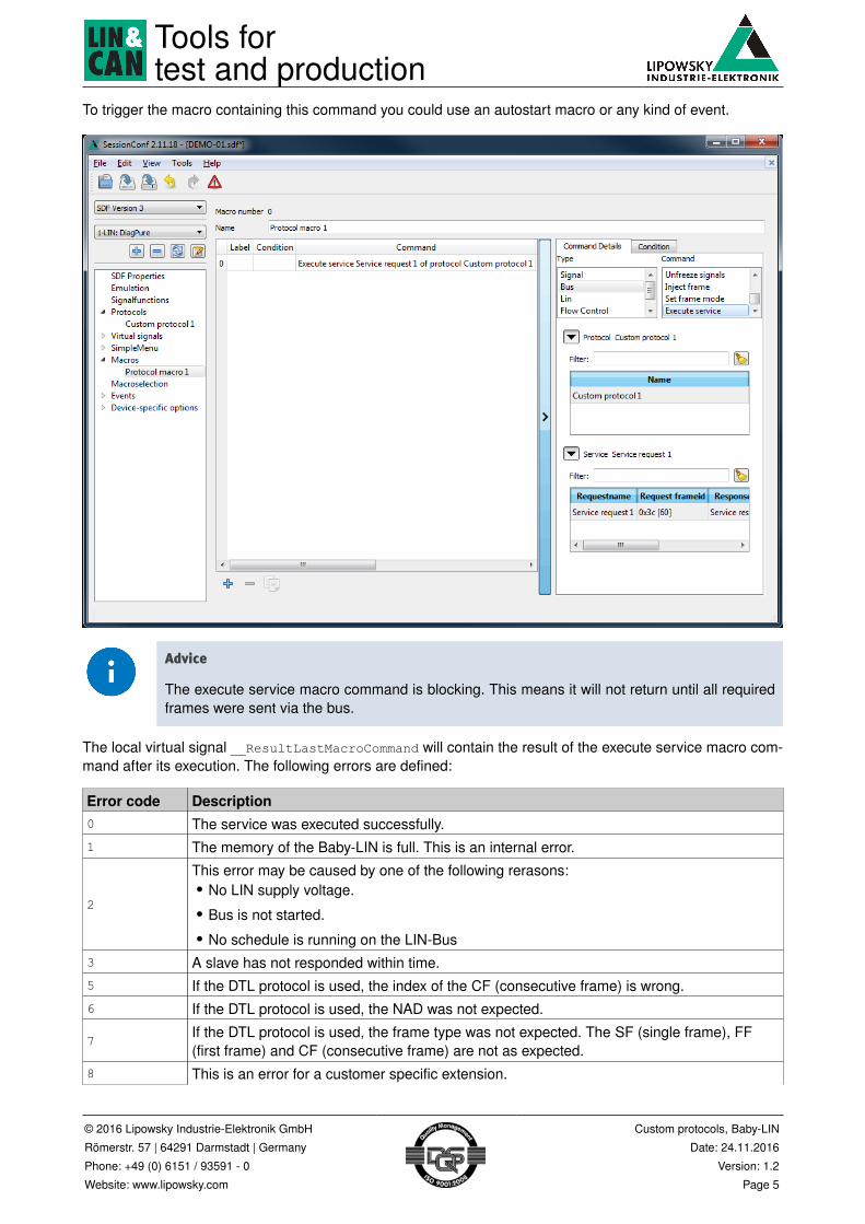
To trigger the macro containing this command you could use an autostart macro or any kind of event.
Advice
The execute service macro command is blocking. This means it will not return until all requiredframes were sent via the bus.
The local virtual signal __ResultLastMacroCommand will contain the result of the execute service macro com-mand after its execution. The following errors are defined:
Error code Description0 The service was executed successfully.1 The memory of the Baby-LIN is full. This is an internal error.
2
This error may be caused by one of the following rerasons:• No LIN supply voltage.• Bus is not started.• No schedule is running on the LIN-Bus
3 A slave has not responded within time.5 If the DTL protocol is used, the index of the CF (consecutive frame) is wrong.6 If the DTL protocol is used, the NAD was not expected.
7If the DTL protocol is used, the frame type was not expected. The SF (single frame), FF(first frame) and CF (consecutive frame) are not as expected.
8 This is an error for a customer specific extension.

Tools fortest and production
© 2016 Lipowsky Industrie-Elektronik GmbH
Römerstr. 57 | 64291 Darmstadt | Germany
Phone: +49 (0) 6151 / 93591 - 0
Website: www.lipowsky.com
Custom protocols, Baby-LIN
Date: 24.11.2016
Version: 1.2
Page 6
Error code Description9
10
11 Too many services are executed right now.12 The length of the frame data was not as expected.
256...511If the DTL protocol is used, slaves may respond with negative response frames. The errorvalue from that negative response frame is then returned with an offset of 0x100.
3.4 Protocol specific system variables
The following system variables are connected to the protocol feature:
System variable Description
@@SYS_SERVICE_REQUEST_NADContains the NAD that will be used when a request frame is con-structed.
@@SYS_SERVICE_RESPONSE_NAD Contains the NAD after a response was received.
@@SYS_SERVICE_RESPONSE_LEN
Contains the length of the response payload after a response wasreceived. If the protocol type is "Raw", the payload length is equalto the data length. This value is especially interesting, if the payloadlength is variable.
Additionally the following system variables may be of interest when calling multiple services within a singlemacro. These system variables are local to a macro and can only accessed within this macro. You can notaccess their values outside of a macro.
System variable Description__ResultLastMacroCommand Contains the return value of the last macro command.__Return Can be set to change the return value of the current macro.__LocalVariable1
...
__LocalVariable10
Can be used within a macro to store data temporarily without theneed to create additional virtual signals.
Tools fortest and production
© 2016 Lipowsky Industrie-Elektronik GmbH
Römerstr. 57 | 64291 Darmstadt | Germany
Phone: +49 (0) 6151 / 93591 - 0
Website: www.lipowsky.com
Custom protocols, Baby-LIN
Date: 24.11.2016
Version: 1.2
Page 7
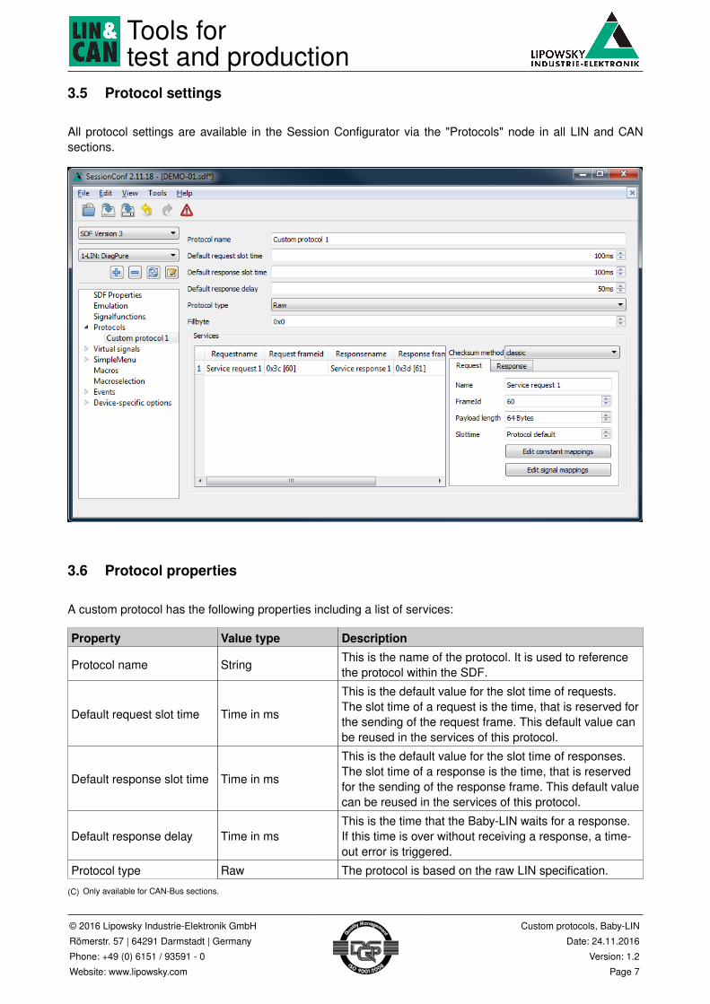
3.5 Protocol settings
All protocol settings are available in the Session Configurator via the "Protocols" node in all LIN and CANsections.
3.6 Protocol properties
A custom protocol has the following properties including a list of services:
Property Value type Description
Protocol name StringThis is the name of the protocol. It is used to referencethe protocol within the SDF.
Default request slot time Time in ms
This is the default value for the slot time of requests.The slot time of a request is the time, that is reserved forthe sending of the request frame. This default value canbe reused in the services of this protocol.
Default response slot time Time in ms
This is the default value for the slot time of responses.The slot time of a response is the time, that is reservedfor the sending of the response frame. This default valuecan be reused in the services of this protocol.
Default response delay Time in msThis is the time that the Baby-LIN waits for a response.If this time is over without receiving a response, a time-out error is triggered.
Protocol type Raw The protocol is based on the raw LIN specification.
(C) Only available for CAN-Bus sections.
Tools fortest and production
© 2016 Lipowsky Industrie-Elektronik GmbH
Römerstr. 57 | 64291 Darmstadt | Germany
Phone: +49 (0) 6151 / 93591 - 0
Website: www.lipowsky.com
Custom protocols, Baby-LIN
Date: 24.11.2016
Version: 1.2
Page 8
Property Value type DescriptionDTL The protocol is based on the DTL specification.
DTL without NAD(C) The protocol is based on the DTL specification but usesno NAD.
<Proprietary types>
These types are especially developed for customers. Ifyou require a custom protocol type, please contact us.Check chapter "Support information" for more informa-tions.
Fillbyte ByteThis is the byte value that is used for bytes that are notoverlapped by signal or constant mappings.
List of services List This is a list of services which can be executed.
(C) Only available for CAN-Bus sections.
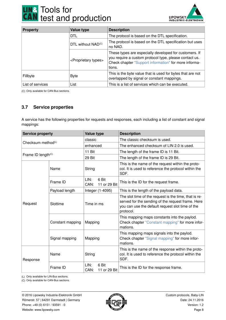
3.7 Service properties
A service has the following properties for requests and responses, each including a list of constant and signalmappings:
Service property Value type Descriptionclassic The classic checksum is used.
Checksum method(L)
enhanced The enhanced checksum of LIN 2.0 is used.
11 Bit The length of the frame ID is 11 Bit.Frame ID length(C)
29 Bit The length of the frame ID is 29 Bit.
Name StringThis is the name of the request within the proto-col. It is used to reference the protocol within theSDF.
Frame IDLIN: 6 BitCAN: 11 or 29 Bit
This is the ID for the request frame.
Payload length Integer (1-4095) This is the length of the payload data.
Slottime Time in ms
The slot time of the request is the time, that is re-served for the sending of the request frame. Hereyou can use the default request slot time of theprotocol.
Constant mapping MappingThis mapping maps constants into the paylod.Check chapter "Constant mapping" for more infor-mations.
Request
Signal mapping MappingThis mapping maps signals into the paylod.Check chapter "Signal mapping" for more infor-mations.
Name StringThis is the name of the response within the proto-col. It is used to reference the protocol within theSDF.Response
Frame IDLIN: 6 BitCAN: 11 or 29 Bit
This is the ID for the response frame.
(L) Only available for LIN-Bus sections.(C) Only available for CAN-Bus sections.
Tools fortest and production
© 2016 Lipowsky Industrie-Elektronik GmbH
Römerstr. 57 | 64291 Darmstadt | Germany
Phone: +49 (0) 6151 / 93591 - 0
Website: www.lipowsky.com
Custom protocols, Baby-LIN
Date: 24.11.2016
Version: 1.2
Page 9
Service property Value type DescriptionPayload length Integer (1-4095) This is the length of the payload data.
Slottime Time in ms
The slot time of the response is the time, that isreserved for the sending of the response frame.Here you can use the default response slot timeof the protocol.
Delay Time in ms
This is the maximum delay that is waited by themaster for a response from the slave. If the slavedoes not answer within time, the service macroreturn value will signal the timeout.
Constant mapping MappingThis mapping maps constants into the paylod.Check chapter "Constant mapping" for more infor-mations.
Signal mapping MappingThis mapping maps signals into the paylod.Check chapter "Signal mapping" for more infor-mations.
(L) Only available for LIN-Bus sections.(C) Only available for CAN-Bus sections.
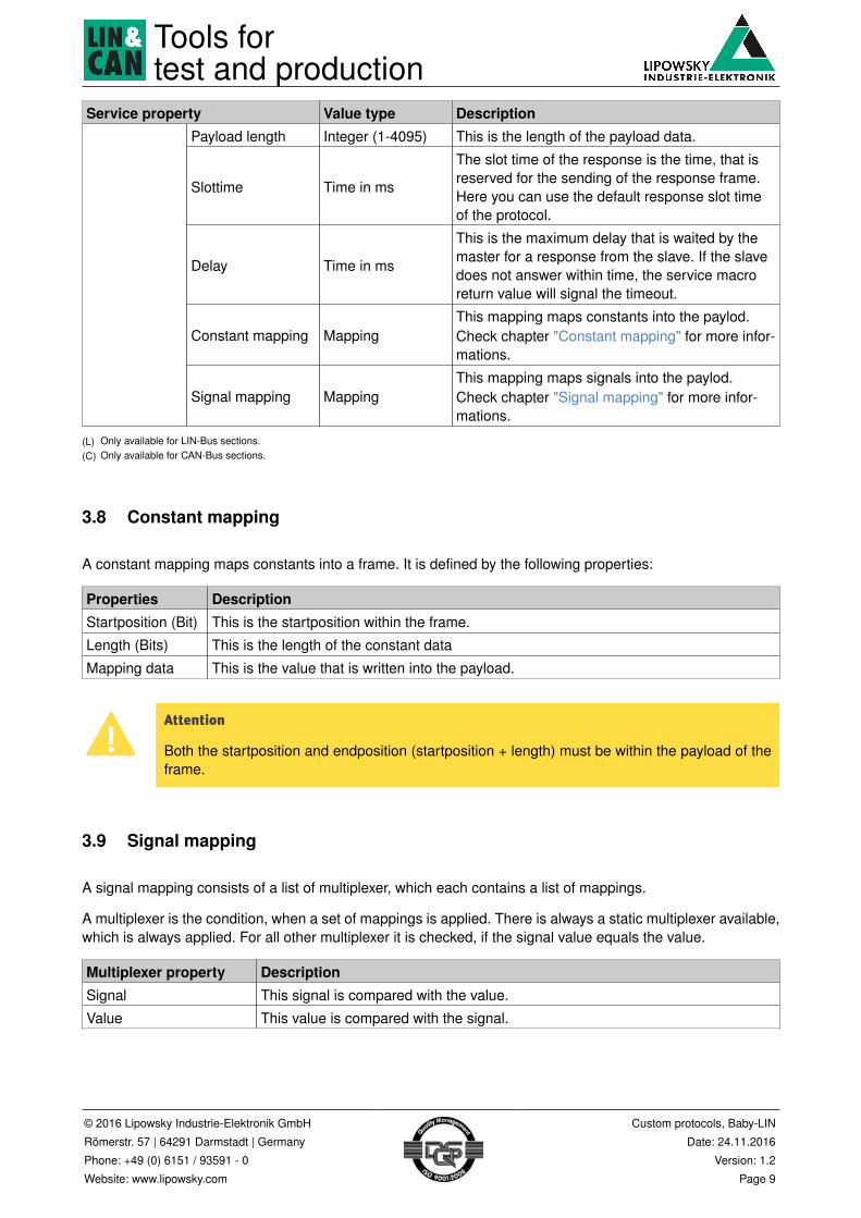
3.8 Constant mapping
A constant mapping maps constants into a frame. It is defined by the following properties:
Properties DescriptionStartposition (Bit) This is the startposition within the frame.
Length (Bits) This is the length of the constant data
Mapping data This is the value that is written into the payload.
Attention
Both the startposition and endposition (startposition + length) must be within the payload of theframe.
3.9 Signal mapping
A signal mapping consists of a list of multiplexer, which each contains a list of mappings.
A multiplexer is the condition, when a set of mappings is applied. There is always a static multiplexer available,which is always applied. For all other multiplexer it is checked, if the signal value equals the value.
Multiplexer property DescriptionSignal This signal is compared with the value.
Value This value is compared with the signal.
Tools fortest and production
© 2016 Lipowsky Industrie-Elektronik GmbH
Römerstr. 57 | 64291 Darmstadt | Germany
Phone: +49 (0) 6151 / 93591 - 0
Website: www.lipowsky.com
Custom protocols, Baby-LIN
Date: 24.11.2016
Version: 1.2
Page 10
Advice
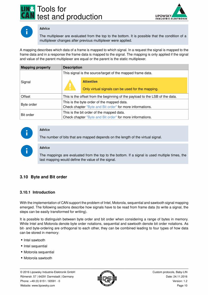
The multiplexer are evaluated from the top to the bottom. It is possible that the condition of amultiplexer changes after previous multiplexer were applied.
A mapping describes which data of a frame is mapped to which signal. In a request the signal is mapped to theframe data and in a response the frame data is mapped to the signal. The mapping is only applied if the signaland value of the parent multiplexer are equal or the parent is the static multiplexer.
Mapping property Description
Signal
This signal is the source/target of the mapped frame data.
Attention
Only virtual signals can be used for the mapping.
Offset This is the offset from the beginning of the payload to the LSB of the data.
Byte orderThis is the byte order of the mapped data.Check chapter "Byte and Bit order" for more informations.
Bit orderThis is the bit order of the mapped data.Check chapter "Byte and Bit order" for more informations.
Advice
The number of bits that are mapped depends on the length of the virtual signal.
Advice
The mappings are evaluated from the top to the bottom. If a signal is used multiple times, thelast mapping would define the value of the signal.
3.10 Byte and Bit order
3.10.1 Introduction
With the implementation of CAN support the problem of Intel, Motorola, sequential and sawtooth signal mappingemerged. The following sections describe how signals have to be read from frame data (to write a signal, thesteps can be easily transformed for writing).
It is possible to distinguish between byte order and bit order when considering a range of bytes in memory.While Intel and Motorola denote byte order notations, sequential and sawtooth denote bit order notations. Asbit- and byte-ordering are orthogonal to each other, they can be combined leading to four types of how datacan be stored in memory:
• Intel sawtooth• Intel sequential•Motorola sequential•Motorola sawtooth

Tools fortest and production
© 2016 Lipowsky Industrie-Elektronik GmbH
Römerstr. 57 | 64291 Darmstadt | Germany
Phone: +49 (0) 6151 / 93591 - 0
Website: www.lipowsky.com
Custom protocols, Baby-LIN
Date: 24.11.2016
Version: 1.2
Page 11
The following table shows how data is located in memory for each combination:
Sawtooth Sequential
Intel
Bit7 6 5 4 3 2 1 0
0 7 6 5 4 3 2 1 0
1 15 14 13 12 11 10 9 8
2 23 22 21 20 19 18 17 16
3 31 30 29 28 27 26 25 24
4 39 38 37 36 35 34 33 32
5 47 46 45 44 43 42 41 40
6 55 54 53 52 51 50 49 48
Byte
7 63 62 61 60 59 58 57 56
Bit0 1 2 3 4 5 6 7
0 0 1 2 3 4 5 6 7
1 8 9 10 11 10 13 14 15
2 16 17 18 19 20 21 22 23
3 24 25 26 27 28 29 30 31
4 32 33 34 35 36 37 38 39
5 40 41 42 43 44 45 46 47
6 48 49 50 51 52 53 54 55
Byte
7 56 57 58 59 60 61 62 63
Motorola
Bit7 6 5 4 3 2 1 0
7 63 62 61 60 59 58 57 56
6 55 54 53 52 51 50 49 48
5 47 46 45 44 43 42 41 40
4 39 38 37 36 35 34 33 32
3 31 30 29 28 27 26 25 24
2 23 22 21 20 19 18 17 16
1 15 14 13 12 11 10 9 8
Byte
0 7 6 5 4 3 2 1 0
Bit0 1 2 3 4 5 6 7
7 56 57 58 59 60 61 62 63
6 48 49 50 51 52 53 54 55
5 40 41 42 43 44 45 46 47
4 32 33 34 35 36 37 38 39
3 24 25 26 27 28 29 30 31
2 16 17 18 19 20 21 22 23
1 8 9 10 11 12 13 14 15
Byte
0 0 1 2 3 4 5 6 7
When data is stored in one of these combinations and transmitted over a LIN- or CAN-Bus, it has to be inter-preted by the receiving side. The receiver has to extract signals from the data and therefor has to know howthe data was originally mapped by the sender. Vice versa, a sender might need to map a signal in a specificmapping to transmit it to a receiver. In general it should be possible to tell a signal mapping of a frame whichof the four types it belongs to. However, the LDF specification does not allow to specify a type and denotesIntel sawtooth as the default. The DBC specification distinguishes between Intel and Motorola mappings whichimplicate sawtooth bit ordering.
3.10.2 Definitions
For a frame we have the following informations:
• fsize frame size in bytes• fdata[fsize] byte array of frame data
We assume fdata to be present in Intel sawtooth notation in which fdata[8] looks as follows (the numbersin the table cells denote the overall bit number of the cell):
Bit7 6 5 4 3 2 1 0
[0] 7 6 5 4 3 2 1 0fdata
[1] 15 14 13 12 11 10 9 8
Tools fortest and production
© 2016 Lipowsky Industrie-Elektronik GmbH
Römerstr. 57 | 64291 Darmstadt | Germany
Phone: +49 (0) 6151 / 93591 - 0
Website: www.lipowsky.com
Custom protocols, Baby-LIN
Date: 24.11.2016
Version: 1.2
Page 12
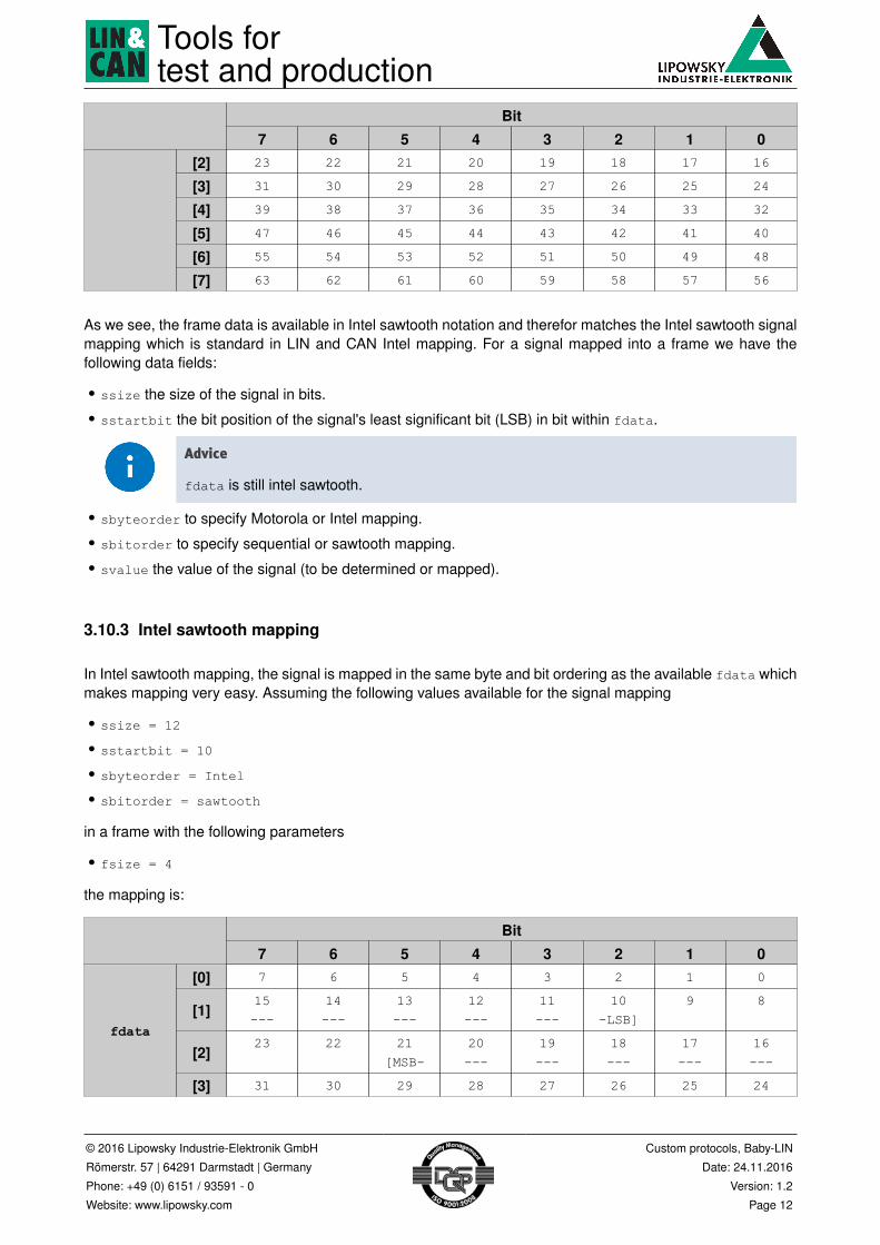
Bit7 6 5 4 3 2 1 0
[2] 23 22 21 20 19 18 17 16
[3] 31 30 29 28 27 26 25 24
[4] 39 38 37 36 35 34 33 32
[5] 47 46 45 44 43 42 41 40
[6] 55 54 53 52 51 50 49 48
[7] 63 62 61 60 59 58 57 56
As we see, the frame data is available in Intel sawtooth notation and therefor matches the Intel sawtooth signalmapping which is standard in LIN and CAN Intel mapping. For a signal mapped into a frame we have thefollowing data fields:
• ssize the size of the signal in bits.• sstartbit the bit position of the signal's least significant bit (LSB) in bit within fdata.
Advice
fdata is still intel sawtooth.
• sbyteorder to specify Motorola or Intel mapping.• sbitorder to specify sequential or sawtooth mapping.• svalue the value of the signal (to be determined or mapped).
3.10.3 Intel sawtooth mapping
In Intel sawtooth mapping, the signal is mapped in the same byte and bit ordering as the available fdata whichmakes mapping very easy. Assuming the following values available for the signal mapping
• ssize = 12
• sstartbit = 10
• sbyteorder = Intel
• sbitorder = sawtooth
in a frame with the following parameters
• fsize = 4
the mapping is:
Bit7 6 5 4 3 2 1 0
[0] 7 6 5 4 3 2 1 0
[1]15---
14---
13---
12---
11---
10-LSB]
9 8
[2]23 22 21
[MSB-20---
19---
18---
17---
16---
fdata
[3] 31 30 29 28 27 26 25 24

Tools fortest and production
© 2016 Lipowsky Industrie-Elektronik GmbH
Römerstr. 57 | 64291 Darmstadt | Germany
Phone: +49 (0) 6151 / 93591 - 0
Website: www.lipowsky.com
Custom protocols, Baby-LIN
Date: 24.11.2016
Version: 1.2
Page 13
If this dataset is transmitted over a bus as above and interpreted as the definition, it looks exactly the same(naturally). The extraction is very easy, as the signal can be extracted using shift operators and logical operators.
3.10.4 Intel sequential mapping
Although it is not available in LDF or DBC specifications, we will now focus on the Intel sequential mapping.
We again assume a 12 bit signal with LSB mapped to bit position 10, this time in Intel sequential frame dataof 4 bytes:
Bit0 1 2 3 4 5 6 7
[0] 0 1 2 3 4 5 6 7
[1]8 9 10
[LSB-11---
10---
13---
14---
15---
[2]16---
17---
18---
19---
20---
21-MSB]
22 23fdata_seq
[3] 24 25 26 27 28 29 30 31
When this dataset is sent like shown above but interpreted as the definition, the resulting fdata set looks asfollows:
Bit7 6 5 4 3 2 1 0
[0] 7 6 5 4 3 2 1 0
[1]15 14 13
[LSB-12---
11---
10---
9---
8---
[2]23---
22---
21---
20---
19---
18-MSB]
17 16fdata
[3] 31 30 29 28 27 26 25 24
with
• ssize = 12
• sstartbit = 13 (LSB)
• sbyteorder = Intel
• sbitorder = sequential
• fsize = 4
to extract the signal we would like to have the data ordered in a way that the signal data is easily extractable.To do so, one possibility is to invert every byte in memory bitwise. The resulting set looks like this:
Bit7 6 5 4 3 2 1 0
[0] 7 6 5 4 3 2 1 0
fdata[1]
15---
14---
13---
12---
11---
10-LSB]
9 8

Tools fortest and production
© 2016 Lipowsky Industrie-Elektronik GmbH
Römerstr. 57 | 64291 Darmstadt | Germany
Phone: +49 (0) 6151 / 93591 - 0
Website: www.lipowsky.com
Custom protocols, Baby-LIN
Date: 24.11.2016
Version: 1.2
Page 14
Bit7 6 5 4 3 2 1 0
[2]23 22 21
[MSB-20---
19---
18---
17---
16---
[3] 31 30 29 28 27 26 25 24
as the LSB position has been flipped, startbit_flip has to be calculated by flipping it, too:
bit = startbit % 8byte = startbit / 8newBit = 7-startbitsstartbit_flip = byte*8+newBit
The signal can now be extracted as Intel sawtooth by using sstartbit_flip as the start bit of the signal.
3.10.5 Motorola sawtooth mapping (Motorola forward LSB)
3.10.5.1 Mapping
In Motorola sawtooth mapping, the signal was mapped in a different byte order (but the same bit order) asthe available fdata.
Assume the following signal in Motorola sawtooth notation:
Bit7 6 5 4 3 2 1 0
[3] 31 30 29 28 27 26 25 24
[2]23 22 21
[MSB-20---
19---
18---
17---
16---
[1]15---
14---
13---
12---
11---
10-LSB]
9 8fdata_be
[0] 7 6 5 4 3 2 1 0
If this data is sent in the order it is shown (from fdata_be[3] to fdata_be[0]) the data we extract by ourdefinition is byte-wise reversed and the bits within the frame are mirrored, too
Bit7 6 5 4 3 2 1 0
[0] 7 6 5 4 3 2 1 0
[1]15 14 13
[MSB-12---
11---
10---
9---
8---
[2]23---
22---
21---
20---
19---
18-LSB]
17 16fdata
[3] 31 30 29 28 27 26 25 24
with
Tools fortest and production
© 2016 Lipowsky Industrie-Elektronik GmbH
Römerstr. 57 | 64291 Darmstadt | Germany
Phone: +49 (0) 6151 / 93591 - 0
Website: www.lipowsky.com
Custom protocols, Baby-LIN
Date: 24.11.2016
Version: 1.2
Page 15
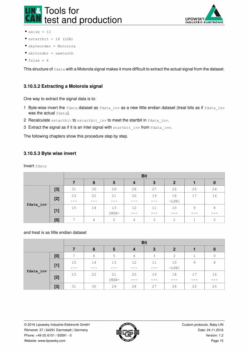
• ssize = 12
• sstartbit = 18 (LSB)
• sbyteorder = Motorola
• sbitorder = sawtooth
• fsize = 4
This structure of fdata with a Motorola signal makes it more difficult to extract the actual signal from the dataset.
3.10.5.2 Extracting a Motorola signal
One way to extract the signal data is to:
1 Byte-wise invert the fdata dataset as fdata_inv as a new little endian dataset (treat bits as if fdata_invwas the actual fdata).
2 Recalculate sstartbit to sstartbit_inv to meet the startbit in fdata_inv.
3 Extract the signal as if it is an Intel signal with startbit_inv from fdata_inv.
The following chapters show this procedure step by step.
3.10.5.3 Byte wise invert
Invert fdata
Bit7 6 5 4 3 2 1 0
[3] 31 30 29 28 27 26 25 24
[2]23---
22---
21---
20---
19---
18-LSB]
17 16
[1]15 14 13
[MSB-12---
11---
10---
9---
8---
fdata_inv
[0] 7 6 5 4 3 2 1 0
and treat is as lillte endian dataset
Bit7 6 5 4 3 2 1 0
[0] 7 6 5 4 3 2 1 0
[1]15---
14---
13---
12---
11---
10-LSB]
9 8
[2]23 22 21
[MSB-20---
19---
18---
17---
16---
fdata_inv
[3] 31 30 29 28 27 26 25 24
Tools fortest and production
© 2016 Lipowsky Industrie-Elektronik GmbH
Römerstr. 57 | 64291 Darmstadt | Germany
Phone: +49 (0) 6151 / 93591 - 0
Website: www.lipowsky.com
Custom protocols, Baby-LIN
Date: 24.11.2016
Version: 1.2
Page 16
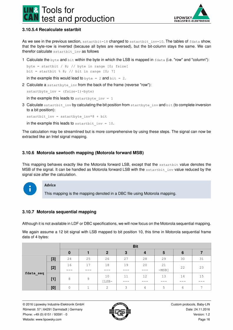
3.10.5.4 Recalculate sstartbit
As we see in the previous section, sstartbit=18 changed to sstartbit_inv=10. The tables of fdata show,that the byte-row is inverted (because all bytes are reversed), but the bit-column stays the same. We cantherefor calculate sstartbit_inv as follows
1 Calculate the byte and bit within the byte in which the LSB is mapped in fdata (i.e. "row" and "column"):
byte = startbit / 8; // byte in range [0; fsize[bit = startbit % 8; // bit in range [0; 7]
in the example this would lead to byte = 2 and bit = 2.
2 Calculate a sstartbyte_inv from the back of the frame (reverse "row"):
sstartbyte_inv = (fsize-1)-byte)
in the example this leads to sstartbyte_inv = 1
3 Calculate sstartbit_inv by calculating the bit position from startbyte_inv and bit (to complete inversionto a bit position):
sstartbit_inv = sstartbyte_inv*8 + bit
in the example this leads to sstartbit_inv = 10.
The calculation may be streamlined but is more comprehensive by using these steps. The signal can now beextracted like an Intel signal mapping.
3.10.6 Motorola sawtooth mapping (Motorola forward MSB)
This mapping behaves exactly like the Motorola forward LSB, except that the sstartbit value denotes theMSB of the signal. It can be handled as Motorola forward LSB with the sstartbit_inv value reduced by thesignal size after the calculation.
Advice
This mapping is the mapping denoted in a DBC file using Motorola mapping.
3.10.7 Motorola sequential mapping
Although it is not available in LDF or DBC specifications, we will now focus on the Motorola sequential mapping.
We again assume a 12 bit signal with LSB mapped to bit position 10, this time in Motorola sequential framedata of 4 bytes:
Bit0 1 2 3 4 5 6 7
[3] 24 25 26 27 28 29 30 31
[2]16---
17---
18---
19---
20---
21-MSB]
22 23
[1] 8 910
[LSB-11---
12---
13---
14---
15---
fdata_seq
[0] 0 1 2 3 4 5 6 7

Tools fortest and production
© 2016 Lipowsky Industrie-Elektronik GmbH
Römerstr. 57 | 64291 Darmstadt | Germany
Phone: +49 (0) 6151 / 93591 - 0
Website: www.lipowsky.com
Custom protocols, Baby-LIN
Date: 24.11.2016
Version: 1.2
Page 17
Sent like this and interpreted as the definition Intel sawtooth the data looks like this:
Bit7 6 5 4 3 2 1 0
[0] 7 6 5 4 3 2 1 0
[1]15---
14---
13---
12---
11---
10-MSB]
9 8
[2] 23 2221
[LSB-20---
19---
18---
17---
16---
fdata
[3] 31 30 29 28 27 26 25 24
with
• ssize = 12
• sstartbit = 21 (LSB)
• sbyteorder = Motorola
• sbitorder = sequential
• fsize = 4
as we see, the signal available "bit flipped" in the data stream. To extract it, we can extract it using simple Intelsawtooth extraction by treating the MSB as the start bit and afterwards "bit flipping" the extracted signal value.

Tools fortest and production
© 2016 Lipowsky Industrie-Elektronik GmbH
Römerstr. 57 | 64291 Darmstadt | Germany
Phone: +49 (0) 6151 / 93591 - 0
Website: www.lipowsky.com
Custom protocols, Baby-LIN
Date: 24.11.2016
Version: 1.2
Page 18
4 Support information
In case of any questions you can get technical support by email or phone. We can use TeamViewer to give youdirect support and help on your own PC. This way we are able to sort out problems fast and direct. We havesample code and application notes available, which will help you to make your job.
Lipowsky Industrie-Elektronik GmbH realized many successful LIN and CAN related projects and therefor wecan draw upon many years of experience in these fields. We also provide turn key solutions for specific appli-cations like EOL (End of Line) testers or programming stations.
Lipowsky Industrie-Elektronik GmbH designs, produces and applies the Baby-LIN products, so you can alwaysexpect qualified and fast support.
Contact informationWebsite: www.lipowsky.com Email: [email protected]
Customer portal: portal.lipowsky.de Telephone: +49 (0) 6151 / 93591 - 0
Shipping address: Lipowsky Industrie-Elektronik GmbH, Römerstr. 57, 64291 Darmstadt, Germany