WebControl® Quick Reference Guide - HTC Controls Ctrl Guide/Quick reference Web...Geographic tree:...
16
WebControl® Quick Reference Guide BUILDING AUTOMATION SYSTEM BUILDING AUTOMATION SYSTEM htc HTC CONTROLS TEL: 416 231 3636
Transcript of WebControl® Quick Reference Guide - HTC Controls Ctrl Guide/Quick reference Web...Geographic tree:...

WebControl®Quick
Reference Guide
BUILDING AUTOMATION SYSTEMBUILDING AUTOMATION SYSTEM
htcHTC CONTROLS
TEL: 416 231 3636
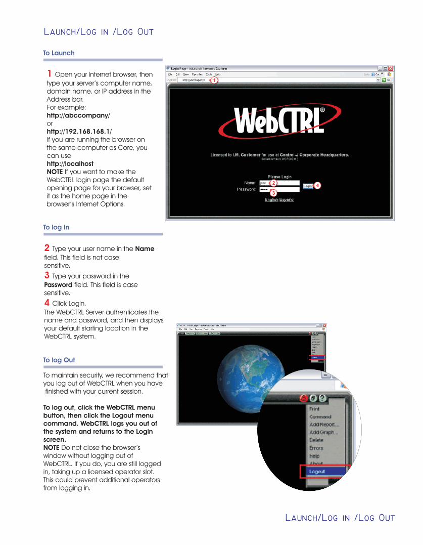
1 Open your Internet browser, then
type your server’s computer name,domain name, or IP address in theAddress bar.For example:http://abccompany/orhttp://192.168.168.1/If you are running the browser onthe same computer as Core, youcan usehttp://localhostNOTE If you want to make theWebCTRL login page the defaultopening page for your browser, setit as the home page in thebrowser’s Internet Options.
To Launch
Launch/Log in /Log Out
Launch/Log in /Log Out
To log In
2
3
4
Type your user name in the Name
field. This field is not casesensitive.
Type your password in the
Password field. This field is casesensitive.
Click Login.
The WebCTRL Server authenticates thename and password, and then displaysyour default starting location in theWebCTRL system.
To maintain security, we recommend thatyou log out of WebCTRL when you have finished with your current session.
To log out, click the WebCTRL menubutton, then click the Logout menucommand. WebCTRL logs you out ofthe system and returns to the Loginscreen.NOTE Do not close the browser’swindow without logging out ofWebCTRL. If you do, you are still loggedin, taking up a licensed operator slot.This could prevent additional operatorsfrom logging in.
To log Out

Colors and status codes
Colors and status codes
WebCTRL’s graphics use thermographic colors to show the current conditions throughout your system. The color bar shown below appears on many graphics as a reminder of color definitions.
Red is not a Warm condition. Red is an Alarm condition.
Color Condition IndicatedColor Name
Mustard
Purple
Charcoal
Coral
Red
Orange
Dark Blue
Yellow
Light Blue
Gray
White
Light Green
Green
Status Code
none
0 or 15
14
13
2 or 9
8
3
7
4
1
10
6
5
In equipment - viewing in design server mode
In a device - non-operational or no communicationsIn equipment - a hardware or software error
In a device - a download is required or is already in progressIn equipment - a module has stopped
FB error in the equipment
Heating or cooling alarm in the equipment
2nd stage cool - much too warm
2nd stage heat - much too cool
1st stage cool - too warm
1st stage heat - too cool
Unoccupied/inactive
Occupied/active
Free cooling band
In a device - operational or operational read onlyIn equipment - comfortable

Errors
Errors
1
2
If you are running WebCTRL in
normal mode and a page containsan error, a small red triangleappears in the lower right corner tosignify that there is an error. Clickon the triangle to display the Errordialog box.
The Error dialog box lists any
errors on the current page. You canuse the View Debug Info link todescribe problems to TechnicalSupport.

Menu Commands
Menu Commands
1 2
Clicking the menu button opens
a drop-down menu of the system
functions described below.
Menu command
Silence
Command
Add Report
Add Graph
Delete
Errors
Help
About
Logout
Temporarily silences for a 5-minute period an audible alert triggered by an event. This silences the alert only for the event thatcaused it. If a new event that triggers an alert is received during the 5-minute period, another alert will sound.NOTE The Silence menu command is only visible if the operator is receiving an audible alert. See “To configure an operator” inthe Operator security manual.
Opens the Print dialog box. We recommend that you set the print orientation to Landscape. When you click OK on the dialog,WebCTRL prints the contents of the action pane. The path to the current tree item automatically prints as the page header.NOTE The Print command removes the black background of floorplans and equipment graphics.
Opens a dialog box where you can execute any of the supported manual commands. See “Manual commands”.
Opens a dialog box where you create a custom report for the selected tree item by choosing a report template created in ReportDesigner.See “To add a report instance to an item in the navigation tree”.
Opens a dialog box where you create custom trend graphs. See “to configure graphs” in the Trends manual.
Deletes the custom report or custom trend graph that is currently displayed in the action pane.
Reopens the Error dialog box, allowing you to reread an error message. You can use the View Debug Info link in the error window
Opens the WebCTRL help file at a topic relevant to your current location.
Opens a pop-up window that contains information about your WebCTRL software.
Immediately logs out the current operator of WebCTRL.

Program Tool Bars I
Program Tool Bars I
1 2 3
4 5 6 7 8 9 10 11 12
Action pane
Navigation pane
Navigation trees and
view buttons
Action buttons
Categories and items
Display tabs
Back button
Tree ornaments button
System-wide Events button
Show/Hide button
Help button
Menu button
Action paneThe action pane is where you viewinformation and perform actions inWebCTRL.
Navigation pane The navigation pane consists of thetree ornaments menu, the navigationtree, and the view buttons.
Navigation trees and view buttonsUse the navigation tree to select the item that you want to see in the action pane.The four view buttons, located at the bottom of the navigation pane, let you selectwhich navigation tree you want to see.
Click thisbutton...
to view the...
Configuration tree: run-time system options you must configure and other WebCTRL functions
such as Event Simulator and Download.
Geographic tree: the hierarchy of areas and equipment defined in SiteBuilder.
Network tree: a network-oriented view of your system. This generally shows the BACnet network.
The only non-BACnet items in the Network tree are equipment items.
Groups tree: non-hierarchical groups, such as schedule groups.

Program Tool Bars II
Program Tool Bars II
Action buttonsThe following table describes what each action button displays for the selected item in the navigation tree.
Click this button... to view...
a graphic.
all of the control values that may be read from or written to the item.
pages where you view or configure schedules.
a page where you assign reporting actions to event categories
and another page where you view and respond to events that have occurred.
pages where you can view or configure trends.
the control program logic (or GFB) used to control a piece of equipment.
the Checkout Report, Point List Report, Network Status Report, Module Version Report,
Security Report and any custom reports.
a page where you assign privilege sets to operators at specific locations in the system.
his button is only visible if location-dependent security is enabled on the System Settings page.
Display tabs1
2
When you click a Properties, Schedules, Events, Trends, or Reports action button, display tabs appear at the top of
the action pane. The different action buttons produce various display tabs. For example, when you click the drop-down arrow on the Reports button, and then click Maintenance and Point List Report, the displaytabs are Configure and View. Clicking Configure displays the page where you define the information to be included in the report. View displays the report.
To the right of the display tabs, WebCTRL shows the item you selected in the navigation tree, plus the category
and/or item.
Back buttonClick the Back button, located to the left of the actionbuttons, to return to the most recently viewed page. Youcan click this button up to nine times.NOTE Do not use your browser’s navigation buttons tomove through WebCTRL.
System-wide Events buttonClick the System-wide Events button to display events for the entire system. Note that the highlight in the navigation tree jumps to the system level.
A green button indicates that there are no events in the system that need acknowledging.
A yellow button indicates that at least one non-critical event in the system needs acknowledging.
A red button indicates that at least one critical event in the system needs acknowledging.

Properties & Graphics Pages
Properties pages are automatically generated from control programs created in Eikon for WebCTRL. Properties pages show the status of a piece of equipment and the properties currently stored in the control module.
Select a piece of equipment or a microblock on the Geographic or Network tree, then click Properties.
NOTE You must resolve any condition, shown as red text at the top of the page, before a Properties page can obtain current information from its control module.
Click the plus and minus icons to show and hide sections as needed.
Do one of the following to change a property:
!Select or clear a checkbox.
!Select an item from a drop-down list.
!Change text in a text field.
Click Accept.
NOTES
! Click the bold, underlined microblock name to open the microblock's Properties page.
! Ctrl-click any property field on any WebCTRL page to view or edit microblock details.
! Alt-click any property field on any WebCTRL page to open the Global Modify dialog box.
To view or change properties on a Properties page
1
2
3
4
Properties & Graphics Pages
Graphics pages
You can view and adjust your system from Graphics pages.
Some typical controls are listed below.
! Button or switch to turn equipment on or off
! Input field to set a property value
! Drop-down list to select a state
! Interactive room sensor to override an unoccupied schedule
! Setpoint graph to adjust setpoints
! Trend graph to view trend information
! Link to jump to another WebCTRL page or to the Internet

Global Modify
Use the Global Modify feature to do the following:
! View a microblock's full reference name path, control program name, and the privileges required to change its properties.
! View or change a single property in several control programs at one time.
To obtain equipment information and relative paths using Global Modify
1 2
3
4
Click GEO.Click the piece of equipment or
point.Verify Properties at the top of the
action pane is selected. If not, clickProperties.
Alt-click an item, whether a statusvalue or an editable value.NOTE Click the Details tab atpoint level to view or edit moreconfigurable properties.
NOTE To view the Setpoint section ofthe Properties page at equipment level,place your cursor anywhere in theSetpoint graph. When the cursor turnsinto a four-pointed arrow, Alt-click andthe Setpoint section’s Properties pageappears. You can Alt-click on anyproperty to launch the Global Modifydialog box.The Global Modify dialog box displaysany tree-related information. The itemslisted will vary depending where you arein the tree.In this dialog box you can:
Click GEO or NET to change your
view when trying to locateequipment.
Click Show Advanced to display
geographic and network pathinformation. Once clicked, you canalso click on any of the underlinedtext to navigate to that item orlocation.
Copy the Expression to your
computer’s clipboard to be used ingraphics or Enhanced Reports.
Find similar pieces of equipment or
points by clicking Find All.
5
6
7
8
Global Modify

Changing Properties using Global Modify
Changing Properties using Global Modify
You can find all similar points or pieces of equipment by clicking the Find All button on the Global Modify dialog box. See “Global Modify” on page 35 to learn how to open theGlobal Modify dialog box. The Find All button allows you to identify any other items with the same Expression. Then you can view all related status values or globally modifyany or all of the related editable tree items.NOTE You can also use a wildcard (*) as the character of an Equipment Definition.
1
2 7
3
4
5
6
Click the tree item where you
would like to begin the search.For example, click BACTechnologies to find all items in thesystem with the point or piece ofequipment. Or click First Floor tofind all items in the first floor, aswell as all areas under the firstfloor, with that point or piece ofequipment.
Click Find All.
Click Apply Changes.
In the example to the right, multipleoccurrences of the Expressionsetpt/setpoints/occupied_heating.value werefound in the system.
By default, all items in the list are
enabled for a change in value. Tochange the value of only one item,clear the other items’ Enable checkboxes. Then type the item’s newvalue in its New Value field.
Type a value in the Set All To field
or Change All By field. Set All Tois used to change all values to aset value. Change All By is usedto change all values by anincrement.
Click Set All To to apply the set
value.
Or, click Change All By to apply the
increment.

Setpoints
Setpoints
A setpoint is the temperature you want your equipment to maintain. You define separate setpoints for heating and cooling to create a range of desired temperatures.
Setpoint adjustment is the basis of four cost-saving strategies:
Schedules Optimal Start Demand Control Setpoint Optimization (or Trim and Respond)
18° 22°
22°18°
When Set points are too close we might see Alarm condition earlier.
The setpoint graph displays the control program's setpoints as configured on the Properties page. Sometimes the effective setpoint does not match the configured setpoints. This situation may cause the control program to broadcast an unexpected thermographic color. For example, the heating and cooling setpoints for an occupied zone may be 18° and 22°.
To change a setpoint
1
2
3
Click a segment or the gap between segments you want to change.
Type new values in the Heating and Cooling fields at the top of the graph.
You can click and drag a segment or a gap between segments to change setpoints.
Click Accept.
1
2
3

The optimal start routine in zone setpoint microblocks allow equipment to begin heating or cooling a zone before occupancy begins. Zone temperatures can then reach theideal comfort range at the time occupancy begins. Optimal start works by calculating setpoints during the unoccupied periods that are gradually adjusted toward theoccupied setpoints.In WebCTRL you can adjust values that were configured in one of the zone setpoint microblocks in Eikon for WebCTRL.
Optimal Start
Optimal Start
1
2
3
Heating Capacity and Cooling
Capacity The maximum rate (indegrees F/hr) that the zonetemperature could be changed byheating or cooling if the outsidetemperature were 65 degreesFahrenheit.For example, if the equipment wasstronger, or the area smaller, thanwas originally thought when thisvalue was set in Eikon forWebCTRL, the heating or coolingcapacity might be higher.
Heating Design Temp and
Cooling Design Temp The mostextreme outside winter andsummer temperatures at which theequipment must run 100% of thetime to maintain the zonetemperature at a comfortable level.Design temps are based on thegeographic location of the buildingand are determined by ASHRAE.
Hysteresis The amount by which
the input value must fall below trippoint before the microblock’soutput is turned off. The hysteresiscan prevent the microblock fromchanging its value too frequentlywhen the input oscillates aroundthe trip point. For example, if thetrip point is 35 and the hysteresis is2, the microblock’s input must fallto 33 before the output turns off.
4 The Zone Setpoint with Learning Adaptive Optimal Start microblocks can use the adjusted heating and cooling
capacities to calculate current setpoints automatically.

Learning Adaptive Optimal Start
Learning Adaptive Optimal Start
If you use learning adaptive optimal start and the zone does not reach the ideal temperature range by the time occupancy begins or reaches it too soon, then the heating orcooling capacities of the equipment are automatically adjusted up or down for the next unoccupied period.For example, the heating capacity for the zone is 5 degrees per hour. When the zone becomes occupied, the zone temperature is 1 degree below the occupied setpoint,indicating a need for additional heat. Since the zone temperature was low by 1 degree, the heating capacity will be decreased by the light blue learning adaptive optimal startvalue (1 degree below setpoint is in the light blue region). If the light blue learning adaptive optimal start value is 0.06 (see the LtBlue value in the example below), theheating capacity will be adjusted to 4.94 for the next optimal start period. This causes the setpoint adjustment to begin sooner in the next unoccupied period.
1
2
3
4
5
6
These color values are the amount
of adjustment depending on thecolor actually achieved at thebeginning of occupancy.
The learned cooling or heating
capacity is the maximum rate (indegrees Fahrenheit/hour) that thezone temperature could bechanged by heating or cooling ifthe outside temperature was 65degrees Fahrenheit.
The actual or adjusted capacity
calculates the actual heating orcooling capacity of the equipmentat the current outside temperature.
The inhibitor can prevent Optimal
Start from occurring within a certaintime before becoming occupied.
If Learning is allowed, heating and
cooling capacities can beautomatically adjusted whenneeded.
The percentage of heating/cooling
capacity.

Scheduling Equipment
Scheduling Equipment
Schedules allow you to define when a building or zone is occupied and whether or not equipment should run. A schedule affects equipment at and below the area or equipment in the tree where the schedule was entered unless you manually exclude a specific item.
NOTE Do not include preheating or precooling time in your schedules. , a cost-saving strategy, automatically calculates and controls precise preheating and precooling routines.
Optimal Start
Determining a schedule’s priorityWhen multiple schedules have been entered into WebCTRL, the priority of a schedule determines which schedule is followed.You determine a schedule's priority by assigning a schedule priority when you enter the schedule on the Schedules page. For example, the Occupancy schedule categoryhas three default schedule priority levels:
Priority level zeroNormal — a low priority schedule thatrepresents times when the space isnormally occupied and unoccupied.
Priority level oneHoliday — a medium priority schedulethat cannot be Weekly type. A Holidayschedule represents times when theNormal occupancy schedule isoverridden.
Priority level twoOverride — a high priority schedule thatcannot be a Weekly type. An Overrideschedule represents times whenHoliday and Normal schedules areoverridden.
Determining a schedule’s precedenceIf two schedules have the same priority, precedence is determined by:Time The last schedule to be entered takes precedence. However, schedules of the same priority may also merge. For example, if Merge Weekly Schedules is enabled onthe System Settings page, a weekly schedule of 9 to 6 and a weekly schedule of 8 to 5 merge so that the result is an 8 to 6 schedule.Locality The more locally a schedule is entered within the tree hierarchy, the greater its precedence. For example, a schedule entered for a piece of equipment on Floor 1has precedence for that equipment over a schedule of the same priority entered at the system level. Of the two factors affecting a schedule's precedence, locality has ahigher relative importance than time.Check the Results bar in the schedule bar graph when you add schedules to verify the resulting schedule is the one you want to run.
Viewing schedules for a Geographic tree item Each Result bar on the View tab of the Schedules page displays the result of all the schedules that affect the selected tree item. Click a Result bar to view all the schedules that contribute to the resulting schedule.
When multiple schedules affect a single area or piece of equipment, WebCTRL sorts the schedules by priority - the higher the priority, the closer the schedule is to the Result bar. You set a schedule's priority when you add a schedule.

To add a schedule
Schedule categories
NOTES Occupancy is the default WebCTRL schedule category. See if you want to create a different binary or a multi-state category.
New schedules and schedule changes download automatically if the Automatically Download Schedules checkbox is selected for a particular schedule. Click the Show Advanced button under the schedule table to access the checkbox.
In the Geographic tree, select the area or equipment you want to schedule.
Click Schedules, then click the Configure tab.
Click Add.
Select a Priority. (Normal is low priority; Holiday is medium; Override is high.)
Select a Type. See table below.
Type a schedule name in the Description field.
Enter desired values in the fields below the Description.
Define occupied schedule times by doing one of the following:
!Click and drag the entire segment with the move
cursor.
!Click and drag either end of the schedule segment
with the pointing-hand cursor.
!Click the segment and type exact times in the fields
above the segment.
!Click Show Advanced to add or delete schedule
segments.
Click Accept.
Type Schedule runs
Weekly
Every week on the specified days
Date
On a single, specified date
Date Range
Between two specified dates
Date List
On multiple, specified dates
Wildcard
According to a repeating pattern (for example, the second Tuesday of every month)
Continuous
Continuously between specified times on two separate dates
Dated Weekly
Weekly between a start date and an end dateNOTE To use a Dated Weekly schedule with an ExecB control module, you must use the 1.71:032 (or later) ExecB driver.
In the Geographic tree, select the tree item where the schedule was defined.
Click Schedules, then click the Configure tab.
Select the schedule you want to edit or delete.
Edit the fields you want to change or click Delete.
Click Accept.
NOTE WebCTRL automatically deletes expired dated schedules from the database at 3:30 AM every day. But expired schedules remain in the control module until the next time schedules are downloaded to the control module. You can change the deletion time on the Scheduled Tasks tab of the System Settings page.
To edit or delete a schedule
Working with Schedules
Working with Schedules

Manual Commands
Manual Commands
You must have the Manual Commands/Console Operations privilege to issue a manual command.
12
Click Command in the Menu drop-down list.
Type the appropriate manual command in the dialog box that appears.
NOTE You may also press Ctrl+M to launch the manual command dialog box.