11construction.wikispaces.com11construction.wikispaces.com/file/view/Brick+... · Web viewFigure 25...
86
CCC372 Brick and Block Laying 1 SECTION 3 STAGE 3 FIELD OF WORK SKILLS LEARNING PACKAGE NATIONAL CONSTRUCTION STUDIES RESOURCE PROJECT
Transcript of 11construction.wikispaces.com11construction.wikispaces.com/file/view/Brick+... · Web viewFigure 25...
CCC372 Brick and Block Laying 1 SECTION 3
STAGE 3
FIELD OF WORK SKILLS
LEARNING PACKAGE
SECTION 1 - BRICK AND BLOCK TYPES
NATIONAL CONSTRUCTION STUDIES
RESOURCE PROJECT
CCC372 BRICK AND BLOCK LAYING 1
CCC372 Brick and Block Laying 1 SECTION 3
READ
INTRODUCTION
The first section of this package deals with two main aspects:
identifying bricks, blocks and tools manufacture processes and performance of materials.
These two areas include the essential information you will need to complete Assessment Task 1 which addresses the first two leaming outcomes.
1. Identify bricks, blocks, tools and equipment used in brick and block laying.
2. Describe the uses, characteristics, fire rating and strengths and weaknesses of reinforced concrete, brickwork, concrete masonry and mortars.
The information in this section will allow you to cover two specific areas:
the identification of bricks, blocks, tools and equipment used in brick and block laying; and
the uses, characteristics, fire rating and strengths and weaknesses of reinforced concrete, brickwork, concrete masonry and mortars.
The details required to understand these areas will be presented under four topics:
Bricklayer’s Tools; Brick Types; Block Types; and Uses and Characteristics of Bricks, Blocks and Reinforced Concrete and Materials.
CCC372 Brick and Block Laying 1 SECTION 3
IDENTIFYING BRICKS, BLOCKS AND TOOLS
1. BRICKLAYER’S TOOLS
The tools may be classified in accordance with their use and are listed under the following four sub-headings:
measuring tools; aligning tools; laying and pointing tools; and cutting tools.
Measuring Tools
Folding Rule 1 Metre Long
For measuring short distances such as thickness of walls, doors and window openings, and sizes of required portions of bricks such as bats and closers.
Steel Tape
Three to thirty metres long for setting out and checking long measurements such as the overall sizes of buildings and their distance from the boundary of the land.
Gauge Rod
Usually 50mm x 25mm batten three to five metres long. It is marked off in courses of brickwork and is used to regulate the height of corresponding courses at all the main comers of the building. Another face of the gauge rod may be marked off to indicate the height of window sills, door and window heads, ventilator fittings, string courses, storey level, and all other required vertical measurements.
Bevel
With 250mm adjustable blade. Used for marking bricks required to be cut at an angle other than 90 degrees to the faces.
Steel Compasses
200mm to 250mm long. For making a series of small measurements such as gauging arch bricks.

CCC372 Brick and Block Laying 1 SECTION 3
Aligning Tools
Spirit Level
450mm to 1200mm long. Used throughout brickwork construction to determine and check the level of the course and for ensuring the vertical alignment of comers and walls.
Long Straight Edge
Usually varies from three to five metres in length, and from 150mm x 25mm to 200mm x 25mm in cross section. Used with the spirit level to determine and check the level of courses of brickwork.
Large Wooden Square
Framed from 75mm x 25mm, batten with sides about 1200mm long. Used for setting out right angles, comers of buildings.
Plumb Rule with Bob
The selected timber plumb rule should be about 1200mm long and 100mm x 125mm in cross section with a lead bob about 1.3kg in weight. Used for testing the vertical alignment of comers throughout brickwork.
Lines and Steel Pins
Brick courses are laid “to the line” which is stretched taut between the pins held in the mortar joints.
The Line Block
This can be used instead of steel pins and is placed on the external face of a corner.
The Tingle
The tingle or tingle plate is used with the line when constructing long walls. It supports the line, preventing it from sagging or swaying in windy conditions.
Steel Square
A steel square is used to check the set out of comers and for setting out small jobs.
Radius Point or Trammel
A lath or batten pivoting on a fixed point to give a required curved outline in the form of brickwork.

CCC372 Brick and Block Laying 1 SECTION 3
Laying and Pointing Tools
Large Trowel
300mm - 330mm in length, used for spreading mortar beds, applying cross joints, and tapping bricks into position. Also often used for roughly cutting the bricks and for pointing the joints.
Pointing Trowel
Various lengths, used for pointing up joints on good quality work.
Jointers
Made in various shapes and sizes suitable for keyed and recessed joints.
Raking Tool
An adjustable pin or nail supported on two small wheels and used to rake out joints to the specific depth.
Finger Trowel
A thin and narrow blade of steel used for smoothing joints.
Hand Broom
For brushing surplus particles from the face of the finished pointed work.
Larry Pot
Usually a two litre dipper used as a water vessel when softening the mortar on the mortar board.
Cutting Tools
Club, Mash or Lump Hammer
Weight approximately 1.3kg. An impelling tool with general uses, especially in conjunction with the bolster and with punch or chisel.
Bolster
A steel tool with a blade 110mm wide. Used in conjunction with hammer for accurately cutting bricks to required shapes and sizes.

CCC372 Brick and Block Laying 1 SECTION 3
Scutch, with Claw Tool or Comb
Used for trimming the rough faces of cut bricks.
Brick Hammer
Used for rough cutting of bricks or as a hammer.
Masonry Saw
A motor driven abrasive wheel for making difficult or multiple cuts in bricks accurately. Most useful where hard bricks are concerned.
Chisels
Steel tools used with hammer for cutting holes and chases in brickwork and for demolishing work.
Plugging Chisel
A steel tool with narrow blade 6 mm thick used for cutting out hardened mortar joints.
Rubbing Stone
A carborundum block used with water to grind the cut and scutched faces of bricks to a smooth, true finish.
Kit of Tools Usually Carried by Bricklayers
1. 1metre rule 9. raker
2. spirit level 10. hand broom
3. brick hammer 11. club hammer
4. lines with pins and blocks 12. bolster
5. large trowel 13. scutch
6. pointing trowel 14. plugging chisel
7. Larry pot 15. cold chisel
8. jointers 16. steel square
2. BRICK TYPES

CCC372 Brick and Block Laying 1 SECTION 3
By bricks we usually mean clay bricks, made from a variety of clays all though they are and can be made from other materials. The size of a common or standard brick is usually 230mm x 110mm x 76mm.
Blocks have various sizes all larger than bricks, they are made of concrete and used largely in industrial and commercial type construction.
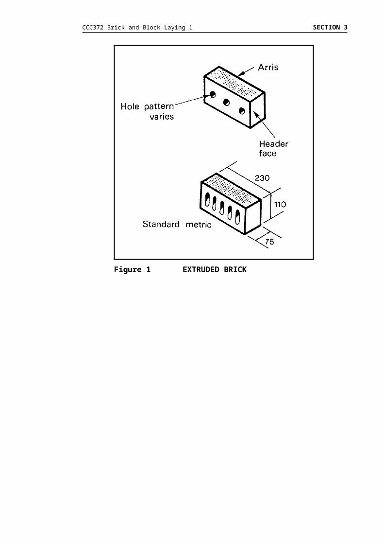
Extruded Brick
Extruded, or as they are also known, wire cut bricks are produced with a variety of hole patterns depending upon the manufacturer and the machines used. These holes reduce the thickness of the clay through which the evaporating water must pass from the denser structure of extruded bricks. The clay used for extruded bricks holds far more water than that used for pressed bricks. This speeds up production, reduces the danger of cracking during firing and permits a more uniform firing of the whole brick.
Figure 1 EXTRUDED BRICK

CCC372 Brick and Block Laying 1 SECTION 3
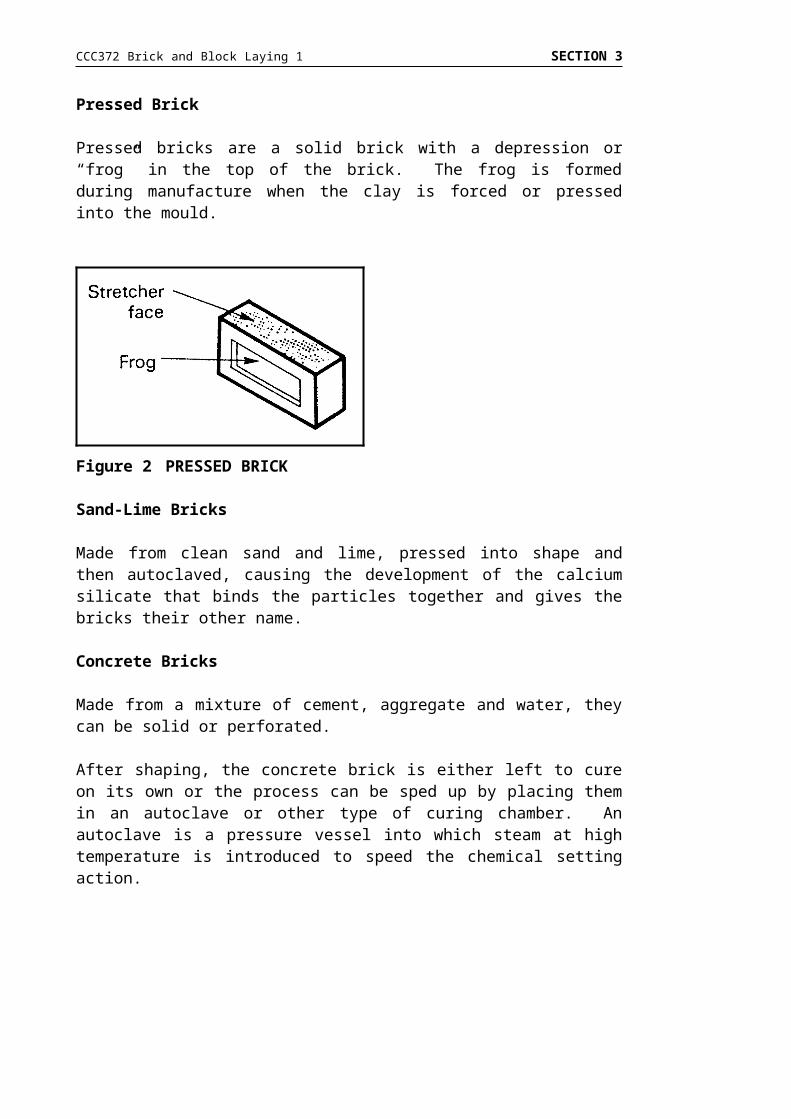
Pressed Brick
Pressed bricks are a solid brick with a depression or “frog” in the top of the brick. The frog is formed during manufacture when the clay is forced or pressed into the mould.
Sand-Lime Bricks
Made from clean sand and lime, pressed into shape and then autoclaved, causing the development of the calcium silicate that binds the particles together and gives the bricks their other name.
Concrete Bricks
Made from a mixture of cement, aggregate and water, they can be solid or perforated.
After shaping, the concrete brick is either left to cure on its own or the process can be sped up by placing them in an autoclave or other type of curing chamber. An autoclave is a pressure vessel into which steam at high temperature is introduced to speed the chemical setting action.
Figure 2 PRESSED BRICK

CCC372 Brick and Block Laying 1 SECTION 3
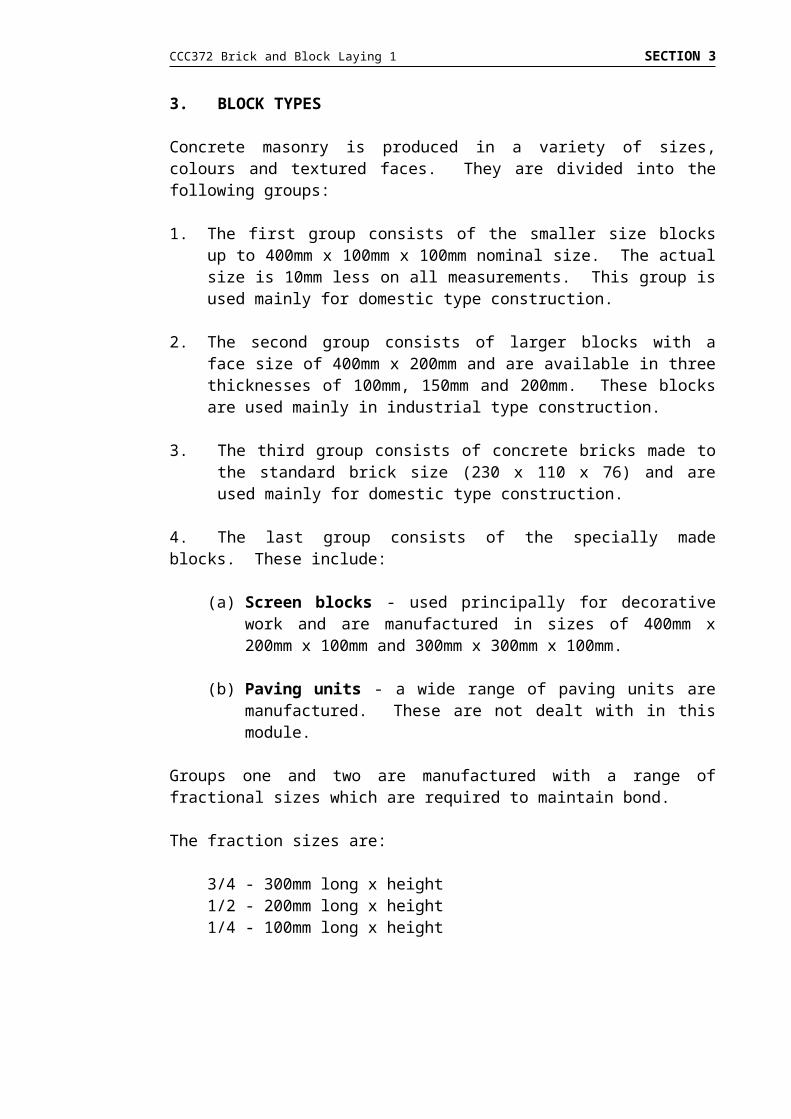
3. BLOCK TYPES
Concrete masonry is produced in a variety of sizes, colours and textured faces. They are divided into the following groups:
1. The first group consists of the smaller size blocks up to 400mm x 100mm x 100mm nominal size. The actual size is 10mm less on all measurements. This group is used mainly for domestic type construction.
2. The second group consists of larger blocks with a face size of 400mm x 200mm and are available in three thicknesses of 100mm, 150mm and 200mm. These blocks are used mainly in industrial type construction.
3. The third group consists of concrete bricks made to the standard brick size (230 x 110 x 76) and are used mainly for domestic type construction.
4. The last group consists of the specially made blocks. These include:
(a) Screen blocks - used principally for decorative work and are manufactured in sizes of 400mm x 200mm x 100mm and 300mm x 300mm x 100mm.
(b) Paving units - a wide range of paving units are manufactured. These are not dealt with in this module.
Groups one and two are manufactured with a range of fractional sizes which are required to maintain bond.
The fraction sizes are:
3/4 - 300mm long x height1/2 - 200mm long x height1/4 - 100mm long x height

CCC372 Brick and Block Laying 1 SECTION 3
Figure 3 VARIOUS BLOCK SIZES

CCC372 Brick and Block Laying 1 SECTION 3
MANUFACTURING PROCESSES AND PERFORMANCE OF MATERIALS
Bricks
Bricks may be classified as being among the most durable of building materials. By bricks we usually mean clay bricks. They are made by the following methods:
Hand moulded Machine pressed (Semi-dry and stiff plastic) Machine extruded (Wire cut).
Hand-made bricks
Due to the very high cost of hand-made bricks, there are few, if any brickworks producing them. Bricks are made by throwing a ball of clay into a brick sized mould and then cutting off the excess clay. Many machine-made bricks are treated to give them some part of the rough and irregular appearance of the hand-made brick.
Machine pressed
Semi-dry pressed bricks are made with about 10-12% (on dry weight) water content. The clay powder is dry enough to fall into the mould under its own weight, where it is then compressed into the desired shape. The resulting brick is smooth and straight with sharp edges and a depression (or frog) in the top face.
Stiff-plastic-pressed bricks are made from clay of 14-17% water content which must be forced by auger into the mould (or die box). The roughly-shaped brick is then moved to a second die box constructed for final pressing. The resulting brick is rougher in appearance than those made by dry-pressing, but their structure is similar.
Machine extruded (wire cut)
Another type of machine is required to make wire cut bricks. Clay with an 18-25% water content is forced by an auger into a horizontal cone-shaped tube which tapers down to the die. The clay column is cut into brick sized pieces by an arrangement of wires. Extruded bricks, although often smooth, may be mechanically patterned or textured.
Drying
Before the bricks are fired, the free-water must be removed. Air-drying is impractical as up to two to three months may be needed to remove the enormous quantities of water involved. Forced drying is generally employed. The bricks are usually set directly on the mobile cars that are passed through the drying and firing stages, without being reset or handled.

CCC372 Brick and Block Laying 1 SECTION 3
Firing
Bricks are fired at temperatures between 1 000°C and 1 200°C, depending on the clay.
The tunnel kiln is the most common kiln where the bricks move past a stationary fire on cars or trolleys. The cars can be loaded and unloaded at the same points in the open factory, simplifying handling. The kiln acts as a conveyor belt at the same time as it fires the bricks.
Quality
Bricks from a kiln are divided into three main quality classes:
1. Firsts - these are the best quality and hand selected. They are used for face work.2. Seconds - these are also selected but have some imperfections in colour or shape
or both. They are also known as commons.3. Thirds - these are over burnt bricks (“clinkers”) and underburnt bricks (“doughboys”).
Blocks
Masonry is produced in a mould which is located in a machine. The ingredients are fed into a large mixer situated above the machine. The ingredients are in the mixer for approximately three minutes, this being 1½ minutes dry mixing and 1½ minutes with the water added. The mixture is dropped into the machine mould and then vibrated to ensure complete filling. The mould is then automatically stripped from the block and the cycle commences again.
Factors necessary for producing good masonry blocks:
1. Good, clean materials.2. Correct grading of materials.3. Optimum amount of water.4. Optimum amount of cement.5. Adequate mixing time to ensure complete dispersion of materials.6. Adequate compaction of material in mould.7. Correct machine setting.8. Well maintained mould and parts.9. Careful handling of “green” blocks into curing kilns.10. Correct curing cycles - especially temperature gradient and maximum temperature.11. Careful handling of block during cubing (packing on pallets), stacking in sheds
and transport to site.
CCC372 Brick and Block Laying 1 SECTION 3
How to Identify a Good Masonry Block
Clean, sharp edges. Closed and even texture, but not sandy. Dimensionally correct. When two blocks are slapped together, a sharp ringing should be heard.
Poorly compacted and dry blocks are always hollow sounding. Appearance of block should be clean and free from core marks. Slight colour variations will occur between batches of block, but colour
should be consistent in any one block.
4. USES AND CHARACTERISTICS OF BRICKS, BLOCKS, REINFORCED CONCRETE AND MORTAR
Bricks and Blocks
Bricks and blocks are the simplest and most ancient of all building materials, but no other fabricated building unit has enjoyed such widespread and continuous popularity. This enduring public acceptance is based on the unique combination of properties which brick offers to the owner and builder. This one material can be used to enclose a structure with a decorative, load bearing weather-bar, which is exceptionally durable and which, if properly constructed in the first place, requires little or no maintenance.
Because of the versatility of the raw material, which can readily be moulded into a great range of shapes and sizes, and the flexibility which this gives to design and construction, building in brick has remained economical. Modern developments in brick construction have shown that when attention is given to efficient site organisation, brick construction can prove cheaper than most of the newly-developed building systems.
They can be load-bearing, as in multi-storey construction (eg supporting the upper level), or non-load bearing as in brick veneer construction or internal partition walling.
The advantages of using bricks and concrete - masonry blocks are:
easily handled; good thermal insulation; good sound insulation; low maintenance; attractive finish; economical; versatility of small unit size; and moulded into various shapes and sizes.
Concrete Masonry is a mixture of course aggregate, fine aggregate (sand), cement and water, made into rectangular units intended for use in bonded masonry construction.
CCC372 Brick and Block Laying 1 SECTION 3
Concrete
Concrete is an artificial rock. It consists of a mixture of course aggregate (stone), fine aggregate (sand), Portland cement and water.
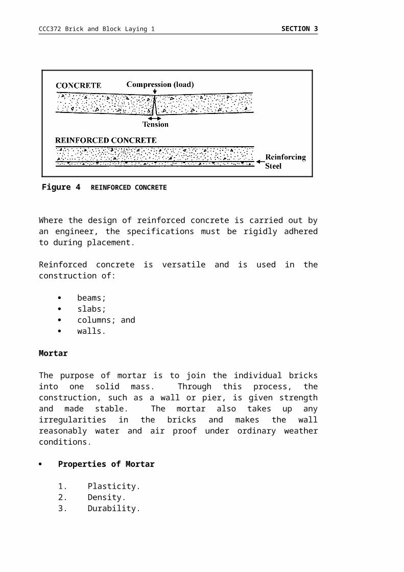
Good concrete is very strong in compression, that is, it will resist forces or loads. It is, however, hard and somewhat brittle and under some circumstances will crack. When concrete is subjected to bending or stretching it is necessary to strengthen it. This is achieved by placing steel in the concrete. When strengthened in this manner it is known as reinforced concrete.
CCC372 Brick and Block Laying 1 SECTION 3
Where the design of reinforced concrete is carried out by an engineer, the specifications must be rigidly adhered to during placement.
Reinforced concrete is versatile and is used in the construction of:
beams; slabs; columns; and walls.
Mortar
The purpose of mortar is to join the individual bricks into one solid mass. Through this process, the construction, such as a wall or pier, is given strength and made stable. The mortar also takes up any irregularities in the bricks and makes the wall reasonably water and air proof under ordinary weather conditions.
Properties of Mortar
1. Plasticity.2. Density.3. Durability.4. Elasticity.5. Strength.6. Appearance.
Figure 4 REINFORCED CONCRETE

CCC372 Brick and Block Laying 1 SECTION 3
Composition of Mortar
Basically, mortar is a mixture of three ingredients:
An aggregate - sand. A matrix - cement and lime. Water.
< AggregateThe best aggregate is a sharp clean pit sand with no more than a 10% clay content. It should be free from loam, vegetable matter and other impurities and if necessary should be washed as the inclusion of foreign matter will weaken the mortar and affect its setting qualities.
< MatrixThe purpose of the matrix is to bind the bricks and the ingredients of the mortar together, into a hard solid mass. The matrix can be rock lime, hydrated lime or Portland cement and it should always be used fresh. It should be stored under adequately dry conditions as any moisture will cause it to partially set.
< WaterWater used in the making of mortar should be clean, drinkable water.
Fire Resistance Ratings
The concept of fire resistance rating has been developed to measure the ability of a structural element to withstand fire whilst continuing to perform its structural function.
Walls and floors must in addition be capable of resisting the transmission of heat from the fire to unaffected areas. This is defined by limiting the increase in temperature of the element on the side away from the fire to a level at which combustible material close to or touching it would not be ignited. It also requires that cracks or fissures which would permit the passage of flame should not develop during a fire.
Fire resistance rating is used also in the converse sense to specify the degree of fire protection required for a structure element.
The property is measured by the endurance time to structural or thermal failure, whichever is earlier, of a standard prototype element, when tested under the provisions of AS1530, under loading conditions comparable to those expected in service.
The fire resistance rating is the standard time, as defined below, which most nearly equals but does not exceed the measured endurance. Standard times for fire resistance ratings are 1, 1½, 2, 3 and 4 hours.
CCC372 Brick and Block Laying 1 SECTION 3
SECTION 2 - SETTING OUT AND LEVELLING
READ
INTRODUCTION
In section 1 you were introduced to tools and equipment needed to lay brick and block work and the manufacturing and characteristics of these masonry units.
This section deals with:
setting out and levelling; setting up materials and equipment; and transferring levels.
These three components include the essential information you will need to complete Assessment Tasks 3, 4 and 6 which address the following learning outcomes:
3. identify and demonstrate setting out and levelling methods.4. set out and position mortar boards and bricks.6. transfer levels.
SETTING OUT AND LEVELLING
1. SETTING OUT
Setting out is the marking out or positioning of walls for a building by using lines and temporary structures (hurdles) to the dimensions given on a plan. It is an extremely important operation, requiring care and accuracy to ensure a square and parallel building.
Tools and Equipment
The tools and equipment required for the setting out operations are:
timber for construction hurdles; builders square approximately 1500mm; nylon line; steel tape; claw hammer and 50 mm nails; club hammer; and saw.

CCC372 Brick and Block Laying 1 SECTION 3
2. LEVELLING
Levelling includes the establishing of a datum point and the transferring of that datum to all comers of the building.
Datum - a reference mark from which all building levels are taken.
Equipment Used
Various types of instruments and equipment have been used to establish and transfer levels around a building site. These include:
dumpy level; tilting level; water level; spirit level and straight edge; Cowley level; automatic level; and laser level.
Of these only the automatic level and laser level is in common use today.
The Automatic Level
There are several types of tripod mounted levels used in the building industry. They can sight a “level” line in any direction.
In automatic levels, the line of sight is levelled automatically (within certain limits) by means of an optical compensator suspended like a pendulum inside the level.
CCC372 Brick and Block Laying 1 SECTION 3
There are a number of different methods of construction and operation of the compensator,shown below is one of them.
The method of distinguishing an automatic level is that the only visible means of levelling it, is a circular plate bubble. Provided the instrument is approximately level, the line of sight is made horizontal by the optical compensator.
Rotating Laser Datum Level (Class 1)
The use of laser beam levels is becoming more and more common in the building and construction industry. They give great accuracy and are suited for one person operation.
All laser levels used in the construction industry must comply with AS2211 “Code of Practice for Laser Safety”, and must be used in accordance with AS2397 “Guide to the Safe Use of Lasers in the Construction Industry”.
These codes set out basic safety standards in the use of laser levels. In the wrong hands and used in an inappropriate manner lasers can be extremely dangerous.
All lasers must have a compliance plate attached to the body of the instrument. Among other information, this plate will give the “Class” of the laser.
You may only use a Class 1 Laser.
Figure 5 AUTOMATIC LEVEL
CCC372 Brick and Block Laying 1 SECTION 3
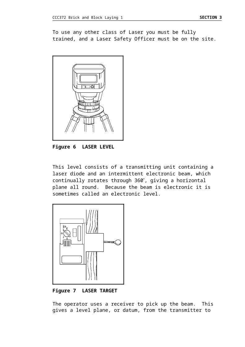
To use any other class of Laser you must be fully trained, and a Laser Safety Officer must be on the site.
This level consists of a transmitting unit containing a laser diode and an intermittent electronic beam, which continually rotates through 360, giving a horizontal plane all round. Because the beam is electronic it is sometimes called an electronic level.
The operator uses a receiver to pick up the beam. This gives a level plane, or datum, from the transmitter to wherever the work is being carried out. The operating radius of the transmitter will vary with brands and types.
The receiver may be attached to a surveying staff, or a timber batten marked for the purpose.
Figure 6 LASER LEVEL
Figure 7 LASER TARGET

CCC372 Brick and Block Laying 1 SECTION 3
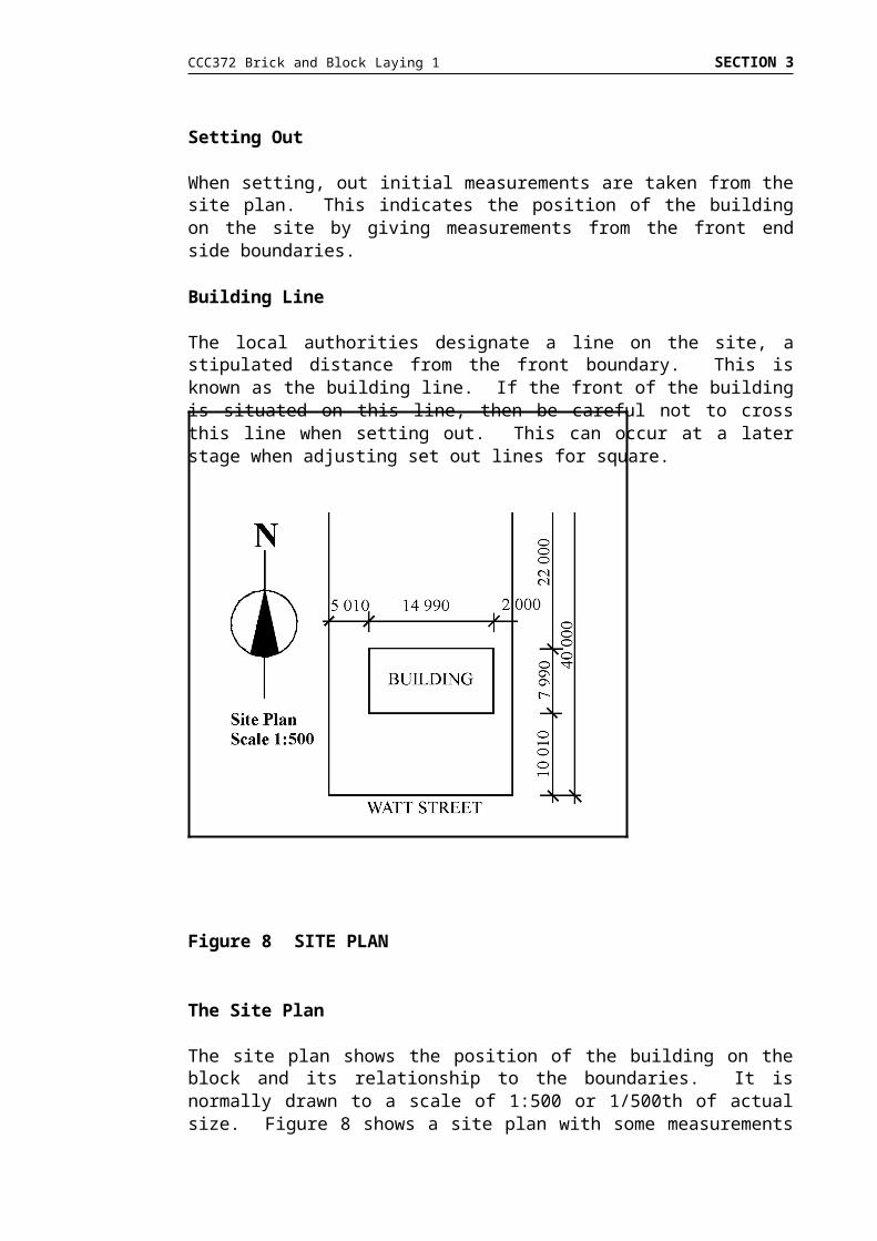
Setting Out
When setting, out initial measurements are taken from the site plan. This indicates the position of the building on the site by giving measurements from the front end side boundaries.
Building Line
The local authorities designate a line on the site, a stipulated distance from the front boundary. This is known as the building line. If the front of the building is situated on this line, then be careful not to cross this line when setting out. This can occur at a later stage when adjusting set out lines for square.
The Site Plan
The site plan shows the position of the building on the block and its relationship to the boundaries. It is normally drawn to a scale of 1:500 or 1/500th of actual size. Figure 8 shows a site plan with some measurements marked on it. These measurements are in metres, the figures 14,990 mean fourteen metres nine hundred and ninety millimetres.
Figure 8 SITE PLAN

CCC372 Brick and Block Laying 1 SECTION 3
3. SETTING OUT METHODS
Setting out involves methods of squaring the corner, measuring, making and placing hurdles and squaring the building.
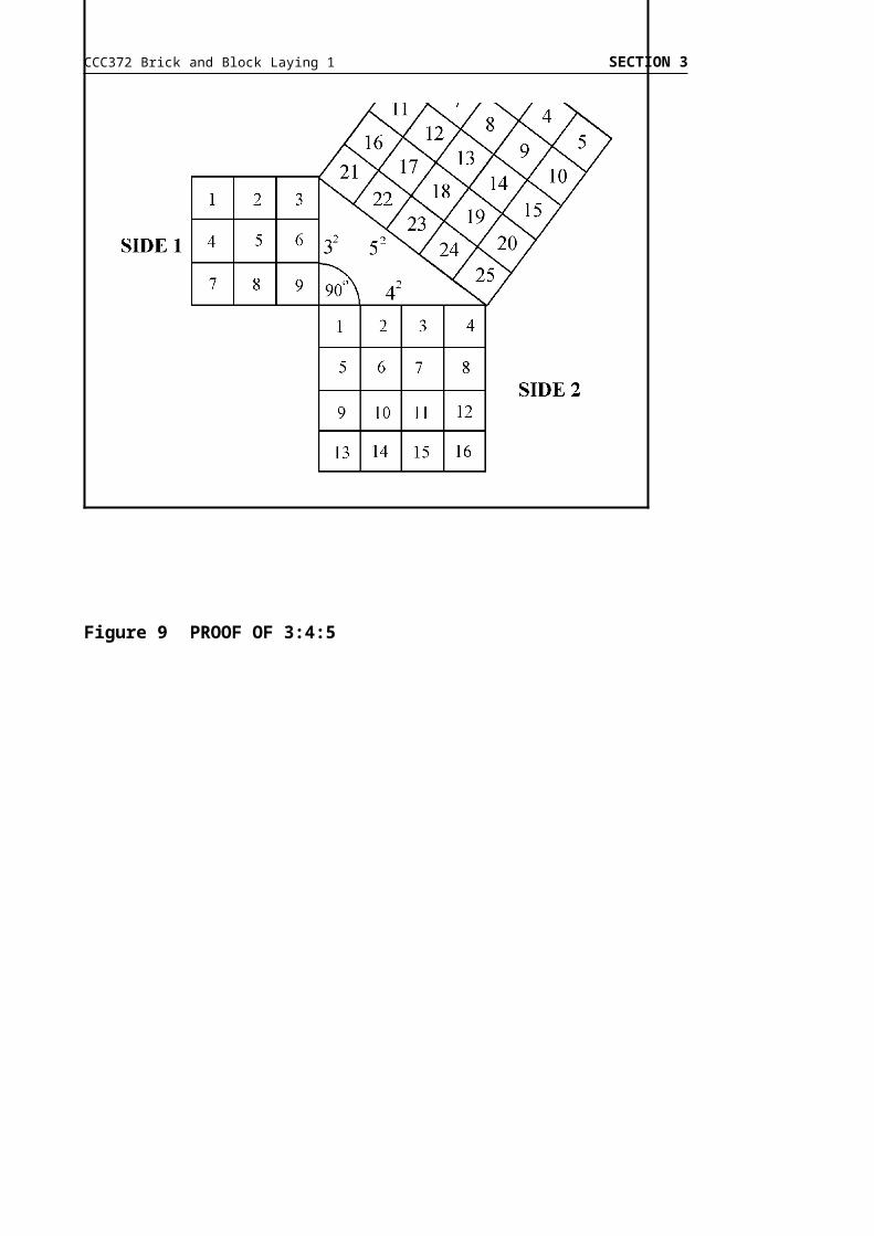
Squaring
A commonly used method of squaring is the 3:4:5 method.
When setting large right angles such as in return brick walling and corners of buildings, a method known as the 3:4:5 rule is used.
This rule is based on a well known theorem in geometry and states:
“If the sum of the squares on two sides of a triangle is equal to the squares on the third side, the triangle is a right-angled triangle”.
Figure 9 PROOF OF 3:4:5

CCC372 Brick and Block Laying 1 SECTION 3
Fixed Builder’s Square
Based on the 3:4:5 rule for right angled triangles.
A typical square is made of 100 x 38 or 25 well seasoned first grade Oregon or Redwood, halved and screwed together and given a protective coat of paint.
It is desirable to have both arms of the square in equal length for accurate working.
Figure 10 FIXED TYPE BUILDER’S SQUARE
CCC372 Brick and Block Laying 1 SECTION 3
Measuring
When setting out a building, distances must be measured with the utmost accuracy. Most faults occur when the building is situated on a sloping site.
When measuring on a sloping site, the measurement must be taken horizontally and not parallel to the slope.
Example
Figure 11 MEASURING ON A SLOPING SITE

CCC372 Brick and Block Laying 1 SECTION 3
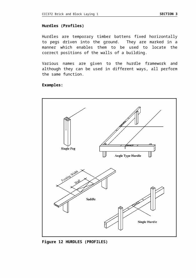
Hurdles (Profiles)
Hurdles are temporary timber battens fixed horizontally to pegs driven into the ground. They are marked in a manner which enables them to be used to locate the correct positions of the walls of a building.
Various names are given to the hurdle framework and although they can be used in different ways, all perform the same function.
Examples:
Figure 12 HURDLES (PROFILES)

CCC372 Brick and Block Laying 1 SECTION 3
Squaring a Building
To check a building for square, it is important to first re-check the measurement of all sides. Having established all measurements are accurate, measure the distance between the diagonal corners. For the building to be square, the diagonal measurements must be the same.
Example:
Figure 13 SQUARING A BUILDING
CCC372 Brick and Block Laying 1 SECTION 3
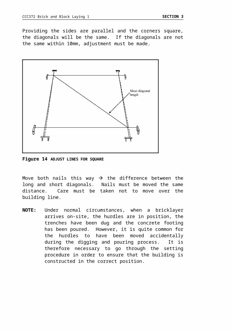
Providing the sides are parallel and the corners square, the diagonals will be the same. If the diagonals are not the same within 10mm, adjustment must be made.
Move both nails this way the difference between the long and short diagonals. Nails must be moved the same distance. Care must be taken not to move over the building line.
NOTE: Under normal circumstances, when a bricklayer arrives on-site, the hurdles are in position, the trenches have been dug and the concrete footing has been poured. However, it is quite common for the hurdles to have been moved accidentally during the digging and pouring process. It is therefore necessary to go through the setting procedure in order to ensure that the building is constructed in the correct position.
Figure 14 ADJUST LINES FOR SQUARE

CCC372 Brick and Block Laying 1 SECTION 3
4. LEVELLING
It can be said that all bricklaying is done “on the level”, ie horizontally. In brickwork, horizontal means exactly horizontal and not just approximately horizontal. Continuous checking of horizontal is essential.
The “near enough” approach creates problems not only for the bricklayer as the job proceeds, but also for other tradespeople.
Automatic Level
Basic Principles
< accurate levelling at the start of a construction job cannot be stressed too much; and
< the automatic level, a combination of a sensitive spirit-level with a short telescope, is a most convenient instrument for rapid and accurate levelling.
Tripod
< legs pressed firmly into ground; and< tripod would be approximately vertical.
Attaching Telescope
< automatic level base is screwed on top of tripod; and< immediately above this is a further plate which carries the vertical axis
upon which the telescope is able to revolve in a horizontal plane.
Telescope
< this contains an optical system of lenses powerful enough to enable the divisions on the staff to be read at considerable distances; and
< inside the telescope is a diaphragm, which carries an extremely fine, horizontal hair line known as the web, or the sighting line.
Level Adjustments
< On top, or at the side of the telescope, is a sensitive spirit level bubble. This enables the telescope to be adjusted by levelling screws.
Once an instrument is set up correctly, a datum can be established and transferred around the job.

CCC372 Brick and Block Laying 1 SECTION 3
Establishing a Datum
A datum is used on all types of construction and can be marked on a concrete or steel column when building partition walls, or on a wooden peg driven into the ground at the corner of a building. Under normal circumstances, a datum will be fixed at a height which corresponds with brick or block work gauge in relation to the working surface.
Care must be taken to measure or ‘gauge down’ from a datum mark to ensure that any discrepancy in concrete levels will be shown at or below ground level.
Transferring a Datum
Transferring a datum is a two person operation with one operating the instrument and the other carrying the staff.
The bottom of the staff is placed on the datum and the reading from the staff noted by the operator. The staff is then placed on pegs or columns at each required point, the previous reading taken and the bottom of the staff is marked.
All marks will then be on a horizontal plane and walls are constructed with constant reference to the marks to ensure that the building stays level.
Laser Level
The procedure when using a laser level is the same as the automatic level but can be operated by one person.

CCC372 Brick and Block Laying 1 SECTION 3
SETTING UP MATERIALS AND EQUIPMENT
5. LAYOUT OF MATERIALS AND EQUIPMENT
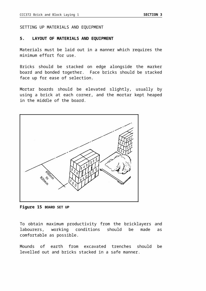
Materials must be laid out in a manner which requires the minimum effort for use.
Bricks should be stacked on edge alongside the marker board and bonded together. Face bricks should be stacked face up for ease of selection.
Mortar boards should be elevated slightly, usually by using a brick at each corner, and the mortar kept heaped in the middle of the board.
To obtain maximum productivity from the bricklayers and labourers, working conditions should be made as comfortable as possible.
Mounds of earth from excavated trenches should be levelled out and bricks stacked in a safe manner.
Bricks and boards should be placed 600 to 800mm away from the face of the wall with boards spaced at a maximum of three metres apart.
Whatever methods are used, it is essential to prevent fatigue for the tradesperson. The working area must be kept clear of debris and materials should be placed at a comfortable distance from the wall.
Figure 15 BOARD SET UP

CCC372 Brick and Block Laying 1 SECTION 3
Locating Mechanical Mixer
Positioning of a mixer will vary depending on the type of site.
This could be a multi-story inner city building requiring a number of mixers or a single housing site in the suburbs.
Points to be considered when setting up are:
availability of water ability to access the site with sand trucks location of power outlet if necessary equipment and materials to be as close as possible to work area.
When the mixer is set up it should be raised off the ground high enough to allow a wheel barrow to be placed beneath the bowl to catch the mortar when it is turned out.

CCC372 Brick and Block Laying 1 SECTION 3
TRANSFERRING LEVELS
6. LEVELLING TERMS
The following basic terms are frequently used in association with levelling using a telescope level.
Assumed Datum (AS)
A datum which is given an assumed height.
An assumed datum is frequently used in building and construction and is commonly assigned a height of 30,000mm or 50,000mm.
Backsight (BS)
This is the first reading taken on the staff after setting up the levelling instrument and is always taken at a point of known or assumed height.
Change Point (CP)
A point at which two readings are taken - one, the last reading taken before moving the levelling instrument, and other taken after resetting the instrument in a new position. It is the point where the foresight and the next backsight readings are taken.
Collimation Line
The line of sight through the centre of the crosshairs of a telescope level.
Datum
A horizontal plane of known height from which reduced levels are measured.
Fall
The amount by which a levelled point is lower than the preceding levelled point. A fall is registered by an increased reading on the staff.
Foresight
The last reading taken on a levelling staff before moving the levelling instrument.
Intermediate Sight (Intersight or IS)
Readings taken on the levelling staff at points between the backsight and the foresight.
CCC372 Brick and Block Laying 1 SECTION 3
Level
a horizontal line or plane a levelling instrument
Level Book
A specially ruled book used by surveyors to record readings.
Levelling Screws
The three screws used for adjusting a levelling instrument to a true level.
Object Glass
The telescope lens nearest to the viewed object.
Reading
The height observed on the levelling staff seen through the crosshairs of the levelling instrument.
Reduced Level (RL)
The height of levelled points in relation to the datum.
Rise
The amount by which a levelled point is higher than the preceding levelled point. A rise is registered by a lower reading on the staff.
Staff
The levelling staff is a measuring rod - graduated into metres and centimetres. The staff is sometimes referred to as the target when taking readings.
Temporary Bench Mark (TBM)
A temporary bench mark is often located at a point on the concrete kerbing or by a peg driven firmly into the ground usually at or close to a corner of a building site.

CCC372 Brick and Block Laying 1 SECTION 3
7. TYPES OF LEVELS
There are a number of different types of levelling instruments in use in the construction industry. These include the water level, spirit level and automatic level. All perform the same function, but not all are suitable for the same jobs.
Water Level
This simple device works on the principle that water finds its own level. Special sight tubes are available made from unbreakable clear plastic with brass fittings at each end.
The cap of the tube incorporates an anti air lock device. The tubes are attached to a hose and filled to about half way up the sight tubes with water.
An improvised water level can be made by attaching a length of clear plastic tube to each end of a hose and sealing the ends with corks.
It is an advantage to use a full length of clear plastic hose so that it can be checked for any trapped air which would prevent any true level readings.
When filling the hose allow water to run through to ensure there is no air trapped inside.
When taking readings, the caps of sight tubes must be released. Also ensure there are no kinks in the hose which may restrict the movement of water.
This method of levelling is widely used by plumbers and ceiling fixers. It is very useful for bricklayers particularly when setting up corners on stepped footings.
This system is limited by the length of tube and is not suitable for levelling over long distances.
CCC372 Brick and Block Laying 1 SECTION 3
Spirit Level
Spirit levels are available in a number of sizes, the most common for bricklayers being 600mm and 1200mm.
The spirit level is used during the bricklaying operation to constantly check the work for horizontal (level) and vertical (plumb).
The spirit level can also be used in conjunction with a straight edge to transfer levels over a longer distance than in normal bricklaying operations although the method described should not be used when precise levels are required.
Figure 16 WATER LEVEL

CCC372 Brick and Block Laying 1 SECTION 3
Spirit Level and Straight Edge
This is not an accurate means of transferring levels over long distances.
The straight edge should be approximately 2.5 metres long and made of well seasoned (cured) dressed timber about 100mm x 40mm in cross section, or similar section in aluminium.
Steps of Procedure
1. Mark the location of the level points A and B and the location of the spirit level X and Y on the straight edge, and level point B with point A.
2. Turn the straight edge and spirit level around end for end (180) each time the level point is transferred to a new location. This allows for any inaccuracies in the straight edge and level.
3. Line up the markings made on the straight edge at points A and B with the level points each time the straight edge has been turned end for end.
4. Ensure the spirit level is positioned correctly on the marks X and Y on the straight edge.
5. Only adjust the new level point each time the level and straight edge are turned end for end.
Figure 17 SPIRIT LEVEL AND STRAIGHT EDGE

CCC372 Brick and Block Laying 1 SECTION 3
Automatic Level
Automatic levels have greatly simplified the taking of levels. If the instrument is set up correctly, the line of sight is automatically levelled by means of an optical compensator (a mirror on a pendulum which moves to maintain the incoming view on a horizontal plane).
Setting up the Automatic Level
1. The tripod is set up with the top plate approximately level.2. The instrument is securely attached using the fastening screw.3. On all automatic levels there is a small circular spirit level which is
centred by adjusting the foot screws.
Step 1: Line up level over two screws and turn screws in opposite directions with finger and thumb until bubble is in line with the centre. (A rule to remember is - The bubble will follow the direction of the left thumb).
Step 2: Without moving the instrument, adjust the third screw until the bubble is central.
Rotate the instrument to check it in all positions.
Step 3: Adjust the eye piece to make the crosshairs sharp and distinct to avoid parallax.
Step 4: Focus the instrument on the target.
CCC372 Brick and Block Laying 1 SECTION 3
8. RECORDING AND REDUCING LEVELS
Staff Reading
There are several types of surveying Staff. However, the one most commonly used in the building industry is known as the “Metric E”.
These are constructed of either aluminium or timber, are telescopic, and from three to five metres long when extended.
On either side of the base is a locking device which holds the telescopic leaves accurately in position. The staff cannot be collapsed without disengaging this locking device.
The staff is read by looking through the telescope of the level while an assistant holds the staff.
The crosshairs are focussed on the staff and the reading is taken on the horizontal hair.
Figure 18 STAFF READING

CCC372 Brick and Block Laying 1 SECTION 3
The staff is marked in:
metres which are shown as the smaller figure - even metres are coloured black and odd metres are red
0.1m or 100mm which are shown as the larger figure 0.01m or 10mm which are shown as one section of the E - the E covers
50mm.
Accuracy using a staff is limited because readings less than 10mm must be estimated.
Using a Level and Staff
To measure level differences on uneven sites, place the level so that both points can be seen without moving the tripod.
Figure 19 STAFF MARKINGS

CCC372 Brick and Block Laying 1 SECTION 3
Place the staff on one of the points and take the reading on the central horizontal hair, and record it.
Move the staff to the second point.
Take and record the reading.
The difference between the readings is the rise or fall of the land.
Figure 20 USING A LEVEL AND STAFF
Figure 21 STAFF READING
CCC372 Brick and Block Laying 1 SECTION 3
9. CONSTRUCTING A STOREY ROD
The principal function of a storey rod (more commonly called a gauge rod) is to regulate the measurement of brick courses throughout the height of the wall.
Because different types and brands of brick vary in size, the standard metric gauge is not always suitable and it is necessary to calculate an appropriate gauge for the masonry unit to be used.
This is done using the following method:
Bricks are taken at random from the stack, allowance is made for a suitable bed joint and the measurement taken of the bricks and joints. The number of bricks selected is usually four to six.
The overall measurement of the selected bricks plus joints is then divided by the number of selected bricks. This gives the average course heights. These measurements are then transferred to the gauge rod.
Example
Bricks selected = 6 @ 76mmSuitable bed joint = 10mm
Bricks overall measurement = 456mmJoints 10mm x 6 = 60mmTotal measurement = 516mm
Average course height = 516mm = 86mm6
Course heights transferred to Gauge Rod = 86mm
The storey rod can also be marked with the heights of window sills and heads and any other relevant information.

CCC372 Brick and Block Laying 1 SECTION 3
SECTION 3 - FOOTINGS AND SLAB ON GROUND
READ
INTRODUCTION
In section 2 you have gained knowledge and skills in:
demonstrating and identifying levelling equipment and levelling methods;
transferring levels; and setting out and positioning materials.
This is the final section in this learning package and deals with:
Footing Types; Interpreting Plans and Specifications; Symbols; and Interpretation of Scales.
Your instructor may decide that your activities in this section be carried out in conjunction with tasks in previous sections.
The components listed include the information you will need to complete Assessment Task 3 which addresses Learning Outcomes 5 and 7.
5. Identify footings and slab on ground construction.7. Interpret plans and specifications.
1. FOOTING TYPES
Footing - the construction whereby the weight of the structure is transferred from the base structure to the foundation. Footings today are of concrete reinforced with steel.
It is necessary to distinguish between the terms “footing” and “foundation” as they are often confused. Foundation is the ground upon which a footing is constructed.

CCC372 Brick and Block Laying 1 SECTION 3
Strip Footings
Concrete strip footings are used extensively and by definition all strip footings are the same. However, the size of the footing will vary depending on the classification of the foundation. This may be stable, intermediate or unstable and must be determined at the design stage.
Details on a plan will show:
depth of footing in the ground; width of footing; depth of concrete; size, type and quantity of reinforcing; and position and minimum cover of reinforcing.
Some examples of strip footing are shown below.
Figure 22 SECTIONS OF STRIP FOOTING
CCC372 Brick and Block Laying 1 SECTION 3
Pier and Beam Footing
Generally, ground which has been filled is unsuitable for foundations because it compresses (packs down) which results in settlement. One method of overcoming this problem is to sink piers or columns of concrete through the filled ground to a solid foundation and then pour a concrete beam or slab on top of the piers or columns.
Type and quantity of reinforcing steel is determined by Engineering Computations.
A more recent development has simplified the placement of footings using the principle of pier and beam construction.
This involves sinking piers of concrete or treated pine posts to a solid foundation and spanning the gap between the posts with angle bars.
Figure 23 PIER AND BEAM FOOTING
Figure 24 TYPICAL SECTION OF WALLING
CCC372 Brick and Block Laying 1 SECTION 3
Slab on Ground Construction
This type extends under the entire building, supports all the wall loadings and serves as the floor.
Engineering Computations are required for this type of construction.
Slab on ground construction is a cheaper alternative to strip footings provided the site is reasonably level. When excavations have to be made to accommodate a level slab then the costs will rise. This is due to the cost of excavation, the building of retaining walls to hold back the excavation and extra drainage to divert water from the high side of the site.
Figure 25 EDGE BEAM SLAB ON GROUND
CCC372 Brick and Block Laying 1 SECTION 3
An example of typical slabs are shown below.
Figure 26 TYPICAL SLABS

CCC372 Brick and Block Laying 1 SECTION 3
2. INTERPRETING PLANS AND SPECIFICATIONS
Plans And Specifications
The smallest out-building and the largest multi-storey building both have one thing in common. That is, they require plans and specifications for their construction.
Builders and tradespeople require that designer’s ideas and details are documented for the construction of any building.
The architect, designer or structural engineer prepares plans, specifications and drawings which set out in detail the work that is to be carried out and the particular types of materials which are to be used.
The architect or designer transforms the client’s ideas and requirements into proposed building forms. The planning and design is a critical stage of any building operation. The architect illustrates his interpretation of the proposed building with perspective sketches, drawings and scale models. From this preliminary work, the architect then produces a set of working drawings and documentation.
To enable all persons engaged in the construction industry to understand and interpret plans and specifications, architects, structural engineers and draftsmen are required to draw all plans to comply with AS Architectural Building and Drawing Practice Code AS 1100.301 1985.
This guarantees uniform scales, symbols and set-out on all plans.
Plans - Working Drawings
When drawn up by the building designer, these show scales, site plans, floor plans, all measurements, elevations, sections, enlarged details, fixtures and their location, legend of symbols and other details necessary for construction.
Specifications
A specification is a document drawn up by the building designer, and is read in conjunction with the working drawings. In the specifications, the architect describes in detail all that is expected in the way of materials and their quality, type of fittings and standard of workmanship.
Clauses are included to cater for inspections by the authorities concerned, and provide for payment of monies and conditions of working.
When the working drawings are in disagreement with the specification, the specification will take precedence over the working drawing.
CCC372 Brick and Block Laying 1 SECTION 3
Plans
There are several types of plans that are used in working drawings. The word “plan” is often wrongly used on the job. The “plan” as used, refers to the complete set of drawings incorporating plans, elevations, sections and detailed drawings. The correct term that incorporates all of these is “working drawings”. It is essential that the working drawings should be fully understood before beginning the construction of the building.
Site Plan
This plan shows the real property description. That is, the allotment number, registered plan number, portion and parish, the shape and dimensions of the allotment, the North point and the name of the street or streets on which the allotment fronts.
Quite often the drainage plan is shown on this drawing, but it can also be a separate plan.
Drainage Plan
A separate plan is required for sewerage or septic tank installations or work of a large nature. House drainage and stormwater drainage may be indicated on the floor plan.
Drainage plans show the outline of the entire site, the proposed building, positions of all drains and fittings such as traps, inspection pipes and access holes.
Where sewerage is to be installed, the position, depth and connection point of the sewer would be shown. If a septic tank is to be installed, the position of the tank, length and location of absorption trenches would be indicated.
Sub-Floor Plan
This is a plan showing the footings and sub-floor walls. The external dimensions are indicated, also the positions and dimensions of all piers, openings and sleeper walls.
Where a sloping site is involved, the use of the underneath area would also be indicated, eg car accommodation, rumpus room, storeroom, laundry, cellar, workshop.
The position of basework walls are not necessarily directly below the walls shown on the floor plan and care must be taken to ensure that the correct plan is read.
Floor Plans
These are drawings showing the layout of a building taken at a level plane cutting through windows, doors and walls.
CCC372 Brick and Block Laying 1 SECTION 3
The arrangement of rooms are shown and named as well as the location and thickness of all external and internal walls. The position and width of all doors and windows are also shown.

CCC372 Brick and Block Laying 1 SECTION 3
All dimensions pertaining to the floor plan are indicated.
Elevations
These drawings show the external walls in the vertical plane and indicate the height of walls from ground level, floor level to ceiling height and the size of window and door openings. The pitch and type of roof is also shown. Roofing material is also specified.
At least two elevations must be shown, ie a front elevation and side elevation, to give a reasonable idea of what is intended.
Four elevations could be required where the building is a little complicated or where two elevations do not show sufficient information.
Sectional Drawings
These drawings represent the view of the building from the highest point to the lowest point through the building. Usually two sections are necessary, one across the building and one lengthwise.
The drawings must be carefully studied as they convey the architect’s or building designer’s requirements as regards to sub-floor concrete thicknesses, wall thicknesses, roof construction, floor construction, finishing heights, damp-proof courses, width of eaves and other special requirements.
Ceiling Plans
These are only required where the treatment of the ceiling is of a complicated nature. Ceiling plans are drawings of the ceiling as it would appear when viewed from the floor.
Roof Plans
These would only be shown if the roof was of a complicated nature. They indicate the spacing of rafters, construction of hips, valleys, ridges, eaves overhang, Dutch gables, sky lights, gutter detail and any other structural details required.
Electrical Plans
These drawings show the electrical circuits and the location of switches, power points, light outlets, meter box and any other electrical requirements.
Details
As most working drawings are drawn to a scale of 1:100 it is not always possible to show clearly all details which are sometimes necessary. To overcome this, a separate drawing of the particular section of work is drawn using a bigger scale 1:5 or 1:10. This allows the building designer to convey to the on-site personnel what is required.

CCC372 Brick and Block Laying 1 SECTION 3
3. SYMBOLS
Materials are represented on drawings either by lettering, hatching, a colour code or by a lined sketch.
Lettering is used to abbreviate the actual names and materials.
For example: AO Access OpeningDPC Damp Proof CourseGI Galvanised Iron
Hatching consists of simply drawing lines at different angles to represent the different materials.
Colours are used in a similar way by using a different colour for each material.
NOTE: The common symbols used in architectural drawings are shown on the following information sheets.
Your instructor will provide a variety of plans and determine the best way for you to become familiar with their features. Make sure you understand the symbols used in each plan.
CCC372 Brick and Block Laying 1 SECTION 3
Figure 27 CROSS HATCHINGS

CCC372 Brick and Block Laying 1 SECTION 3
Figure 28 WINDOW AND DOOR OPENINGS

CCC372 Brick and Block Laying 1 SECTION 3
Figure 29 SERVICES AND SUNDRY SYMBOLS

CCC372 Brick and Block Laying 1 SECTION 3
4. INTERPRETATION OF SCALES
Reduction scales are used in drawing plans so that the drawing can be a manageable size. If a house is drawn full size, or to a scale of 1:1, the drawings would be as large as the house. As you can imagine, they would be almost useless because of their size, so various scales are used to reduce the size of the drawings.
The scale of a drawing must be shown on the drawing somewhere, and is often found in the title block.
Scales are shown in this way: 1:200. The figure on the left is the actual size. The figure on the right is how many times it has been reduced on the drawing - in this case, 200 times. This means that the drawing is 1/200th the size of the completed building. If something on the drawing measures 10mm, its actual size is 2000mm or 10mm x 200.
3. DIMENSIONS
Addition Dimensioning
By working from left to right, all measurements must be added together to obtain the total length of the wall.
Find the overall length.
Running Dimensioning
By working from left to right, the measurement at the arrow head is the total measurement from the point of origin, in this case, the end of the wall to the arrow head.
Figure 30 ADDITION DIMENSIONING

CCC372 Brick and Block Laying 1 SECTION 3
In this example, point A is the point of origin, and the total distance from point A to point C is 3,600 mm.
What is the distance from A to D?
What is the distance from A to E?
Figure 31 RUNNING DIMENSIONING

CCC372 Brick and Block Laying 1 SECTION 3
1. List four (4) cutting tools.2. State three (3) different types of tools that could be used to check
the vertical height of brick courses.3. What are three (3) basic function of a large trowel?4. What is the purpose of a Larry pot?5. Explain the reasons for the holes in extruded bricks.6. How is a frog formed in a pressed brick?7. How are concrete bricks cured?8. List four ways to identify a good masonry block.9. Identify the tools and equipment required for setting out.10. What is meant by the term “datum”?11. Name the types of level in common use today.12. Describe the 3:4:5 method of squaring.13. Explain why it is necessary to gauge down from a datum mark.14. On what principle does a water level operate?15. Explain the method used to determine a suitable gauge.16. Define the term footing.17. Define the term foundation.18. What are the three (3) foundation classifications?19. Describe in your own words, pier and beam.20. Describe Slab on Ground construction.21. What information is conveyed by a specification?22. What is shown by an elevation?23. Which part of the drawing will show the height from floor level to
ceiling?24. What is meant by running dimensioning?