d2n0lz049icia2.cloudfront.net · Web viewOpposite charges always attract. Like charges tend to...
26
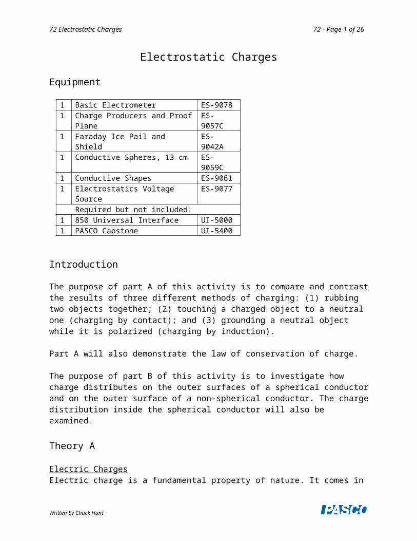
72 Electrostatic Charges 72 - Page 1 of 26 Electrostatic Charges Equipment 1 Basic Electrometer ES-9078 1 Charge Producers and Proof Plane ES- 9057C 1 Faraday Ice Pail and Shield ES- 9042A 1 Conductive Spheres, 13 cm ES- 9059C 1 Conductive Shapes ES-9061 1 Electrostatics Voltage Source ES-9077 Required but not included: 1 850 Universal Interface UI-5000 1 PASCO Capstone UI-5400 Introduction The purpose of part A of this activity is to compare and contrast the results of three different methods of charging: (1) rubbing two objects together; (2) touching a charged object to a neutral one (charging by contact); and (3) grounding a neutral object while it is polarized (charging by induction). Part A will also demonstrate the law of conservation of charge. The purpose of part B of this activity is to investigate how charge distributes on the outer surfaces of a spherical conductor and on the outer surface of a non-spherical conductor. The charge distribution inside the spherical conductor will also be examined. Theory A Electric Charges Electric charge is a fundamental property of nature. It comes in Written by Chuck Hunt
Transcript of d2n0lz049icia2.cloudfront.net · Web viewOpposite charges always attract. Like charges tend to...
72 Electrostatic Charges 72 - Page 1 of 16
Electrostatic Charges
Equipment
1 Basic Electrometer ES-9078 1 Charge Producers and Proof Plane ES-9057C 1 Faraday Ice Pail and Shield ES-9042A 1 Conductive Spheres, 13 cm ES-9059C 1 Conductive Shapes ES-9061 1 Electrostatics Voltage Source ES-9077
Required but not included:1 850 Universal Interface UI-50001 PASCO Capstone UI-5400
Introduction
The purpose of part A of this activity is to compare and contrast the results of three different methods of charging: (1) rubbing two objects together; (2) touching a charged object to a neutral one (charging by contact); and (3) grounding a neutral object while it is polarized (charging by induction).
Part A will also demonstrate the law of conservation of charge.
The purpose of part B of this activity is to investigate how charge distributes on the outer surfaces of a spherical conductor and on the outer surface of a non-spherical conductor. The charge distribution inside the spherical conductor will also be examined.
Theory A
Electric ChargesElectric charge is a fundamental property of nature. It comes in two types, called positive and negative. Positive charge is the type of charge carried by protons. Negative charge is the type of charge carried by electrons. As nearly as can be measured (better than 1 part in 1030), the magnitude of the charge on an electron is the same as the magnitude of the charge on a proton. Atoms normally have the same number of protons and electrons and this balance of charges makes them electrically neutral. Most objects are found in this neutral state. For an object to be positively charged, it has to have more protons than electrons. For an object to be negatively charged, it has to have more electrons than protons, disturbing the neutral charge balance.
Forces between ChargesOpposite charges always attract. Like charges tend to repel. At an elemental level, like charges always repel (electrons repel electrons, protons repel protons), but for macroscopic objects, non-symmetric charge distribution can result in an overall attraction between two objects that carry the same type of overall charge (positive or negative). Non-symmetrical charge distribution always results in an attraction between a charged object and an electrically neutral (overall)
Written by Chuck Hunt
72 Electrostatic Charges 72 - Page 2 of 16
object.
Charging: all charging processes involve the transfer of electrons from one object to another. In order for an object to become positively charged, it must lose some of its electrons. In order for an object to become negatively charged, it must acquire more electrons.
1. Charging by rubbing: When two initially neutral non-conducting objects are rubbed together, one of them will generally bind electrons more strongly than the other and take electrons from the other. The law of conservation of charge requires that the total amount of electrons be conserved. That is, electrons only move from one object to another, but no new electrons are created, nor do they disappear. Overall, the two objects when considered together still have zero net charge.
2. Charging by contact: When a charged object is touched to a neutral (or less charged) object, repulsive forces between the like charges result in some of the charge transferring to the less charged object so the like charges will be further apart. This effect is much larger for conducting objects.
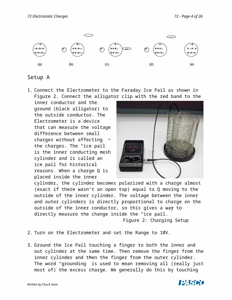
3. Charging by induction: The protons and electrons inside any object respond to electric forces of attraction or repulsion. When an object is placed near a charged object, the charged object will exert opposite forces on the protons and the electrons inside the other object, forcing them to move apart from each other. One side of the object will become more positive than it was initially. The other side will become more negative, as electrons migrate internally. This condition is called polarization, a word that refers to the object having “poles,” or opposite sides with different electrical states, even though the object as a whole may still neutral. If a conductor is touched to the polarized object, some of the charge will transfer to the conductor. If the conductor is then removed, the object now carries a net charge different from its initial charge. For example, consider the sequence in Figure 1. Figure 1a shows an isolated neutral conductor. In Figure 1b, a negatively charged object has been placed near the neutral conductor, which is now polarized. Another conductor (elliptical) is shown but is not yet involved. In Figure 1c, the elliptical conductor touches the polarized conductor and some of negative charge transfers to the elliptical conductor due to repulsive from the negative charged object. In Figure 1d, the elliptical conductor is removed, taking some negative charge with it and leaving a net positive charge on the round conductor. In Figure 1e the negatively charged object has been removed. The charge on the round conductor re-distributes, but the overall charge on the conductor is now positive. Note that we have ignored polarization of the elliptical conductor.
Written by Chuck Hunt
72 Electrostatic Charges 72 - Page 3 of 16
Setup A
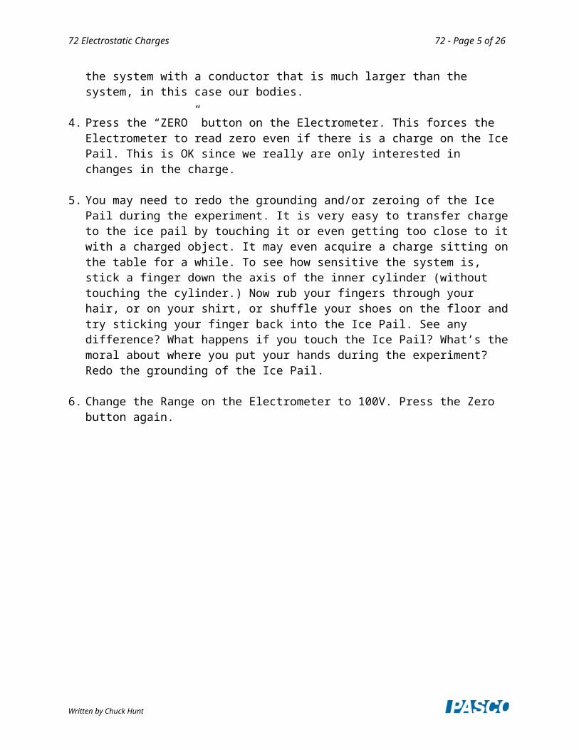
1. Connect the Electrometer to the Faraday Ice Pail as shown in Figure 2. Connect the alligator clip with the red band to the inner conductor and the ground (black alligator) to the outside conductor. The Electrometer is a device that can measure the voltage difference between small charges without affecting the charges. The “ice pail” is the inner conducting mesh cylinder and is called an ice pail for historical reasons. When a charge Q is placed inside the inner cylinder, the cylinder becomes polarized with a charge almost (exact if there wasn’t an open top) equal to Q moving to the outside of the inner cylinder. The voltage between the inner and outer cylinders is directly proportional to charge on the outside of the inner conductor, so this gives a way to directly measure the change inside the “ice pail.”
Figure 2: Charging Setup
2. Turn on the Electrometer and set the Range to 10V.
3. Ground the Ice Pail touching a finger to both the inner and out cylinder at the same time. Then remove the finger from the inner cylinder and then the finger from the outer cylinder. The word “grounding” is used to mean removing all (really just most of) the excess charge. We generally do this by touching the system with a conductor that is much larger than the system, in this case our bodies.
4. Press the “ZERO” button on the Electrometer. This forces the Electrometer to read zero even if there is a charge on the Ice Pail. This is OK since we really are only interested in changes in the charge.
5. You may need to redo the grounding and/or zeroing of the Ice Pail during the experiment. It is very easy to transfer charge to the ice pail by touching it or even getting too close to it with a charged object. It may even acquire a charge sitting on the table for a while. To see how sensitive the system is, stick a finger down the axis of the inner cylinder (without touching the cylinder.) Now rub your fingers through your hair, or on your shirt, or shuffle your shoes on the floor and try sticking your finger back into the Ice Pail. See any difference? What happens if you
Written by Chuck Hunt
72 Electrostatic Charges 72 - Page 4 of 16
touch the Ice Pail? What’s the moral about where you put your hands during the experiment? Redo the grounding of the Ice Pail.
6. Change the Range on the Electrometer to 100V. Press the Zero button again.
Written by Chuck Hunt
72 Electrostatic Charges 72 - Page 5 of 16
7. One at a time, insert the disks on the Charge Producer wands (one with a dark plastic disk and the other with a white leather disk) into the inner basket. Where are your hands? If the disks are uncharged, the needle in the electrometer will stay at zero. If the needle moves, then there is residual charge in the wands. To remove the residual charge, touch the charge producers to the outer basket of the grounded ice pail. Sometimes if residual charge is hard to remove, you can breathe on the disks. The moisture from your breath will remove the charges. It is difficult to remove all the charge since the disks are non-conducting. If you see a voltage change of less than one volt, that is good enough.
Procedure A1: Charging by Rubbing Objects Together
1. Ground the ice pail, zero the electrometer and make sure there is no charge on the charge producing wands (see step7 under Setup A).
2. Hold one wand in each hand and lower them into the lower half of the inner basket, without letting them touch each other or the walls of the basket. Since there is no net charge in either wand, the needle in the monitor should not move and still read nearly zero. Press the Zero button on the Electrometer. Record the “initial” reading in row 1 of Table I.
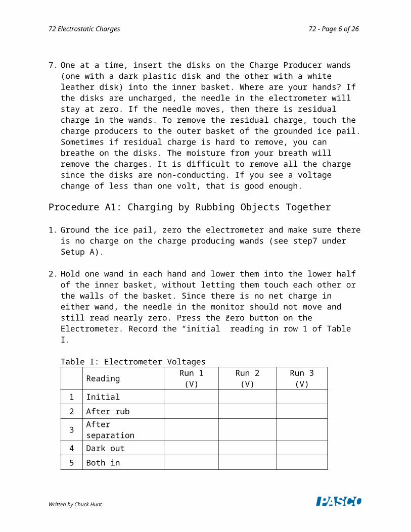
Table I: Electrometer Voltages
Reading Run 1(V)
Run 2(V)
Run 3(V)
1 Initial
2 After rub
3 After separation
4 Dark out
5 Both in
6 White out
7 Final
8 Both out
9 Sum
3. Do all of the following steps as rapidly as possible to minimize charge migration to the surroundings.
4. While inside the basket, briskly rub the two charge producers together and observe the needle in the monitor. Record the “after rubbing” reading in row 2 of Table I.
Written by Chuck Hunt
72 Electrostatic Charges 72 - Page 6 of 16
5. Stop rubbing. Still inside the basket, separate the wands and observe the needle in the monitor. Record the “after separation” reading in row 3 of Table I.
6. Take the dark wand out of the basket. Record the “dark out” reading in row 4 of Table I.
7. Insert the dark wand into the basket with the white wand (not touching). Record the “both in” reading in row 5 of Table I.
8. Remove the white wand. Record the “white out” reading in row 6 of Table I.
9. Insert the white wand into the basket with the dark wand. Record the “final” reading in row 7 of Table I.
10. Remove both wands. Record the “both out” reading in row 8 of Table I.
11. Rub the two wands together and then remove the charge from the white one by touching it to the outside mesh cylinder. Ground the Ice Pail with your finger and zero the Electrometer. Repeat steps 2-10.
12. Rub the two wands together and then remove the charge from the black one. Ground the Ice Pail and zero the Electrometer. Repeat steps 2-10.
Analysis A1
1. What can you immediately conclude about the charges on the white wand and the dark wand based on the signs of the voltages in Run 1?
2. Note that lines 3, 5, and 7 are exactly the same system so should have the same voltage. Any difference implies that there has been some charge lost or gained. In addition, line 8 should be zero unless some charge has transferred. Looking at these should allow you to estimate the uncertainties in the experiment and decide if numbers agree within the uncertainties.
3. Recall that the voltage is directly proportional to the charge. Thus if a voltage or 8 V implies 8 units of charge, a voltage of 12 V implies 12 units of charge.
4. What do lines 1-3 imply?
5. Add line 4 to line 6 (don’t forget the sign). Enter the sum on line 9.
6. Compare line 1 to line 9. What does this imply?
Procedure A2: Charging by Contact
1. Ground the ice pail and zero the electrometer. Record the "zero" reading in line 1 of Table II.
2. Briskly rub the white and dark charge producers together to charge them.
Written by Chuck Hunt

72 Electrostatic Charges 72 - Page 7 of 16
3. Insert the white charge producer into the inner basket of the ice pail. Record the “initial” voltage on the electrometer in line 2 of Table II.
4. Let the white disk on the charge producer touch the wall of the basket. Record the “after touch” voltage on the electrometer in line 3 of Table II.
5. Remove the white disk. Record the “disk out” voltage on the electrometer in line 4 of Table II.
6. Repeat steps 1-5 using the dark charging disk.
Procedure A3: Charging by Induction
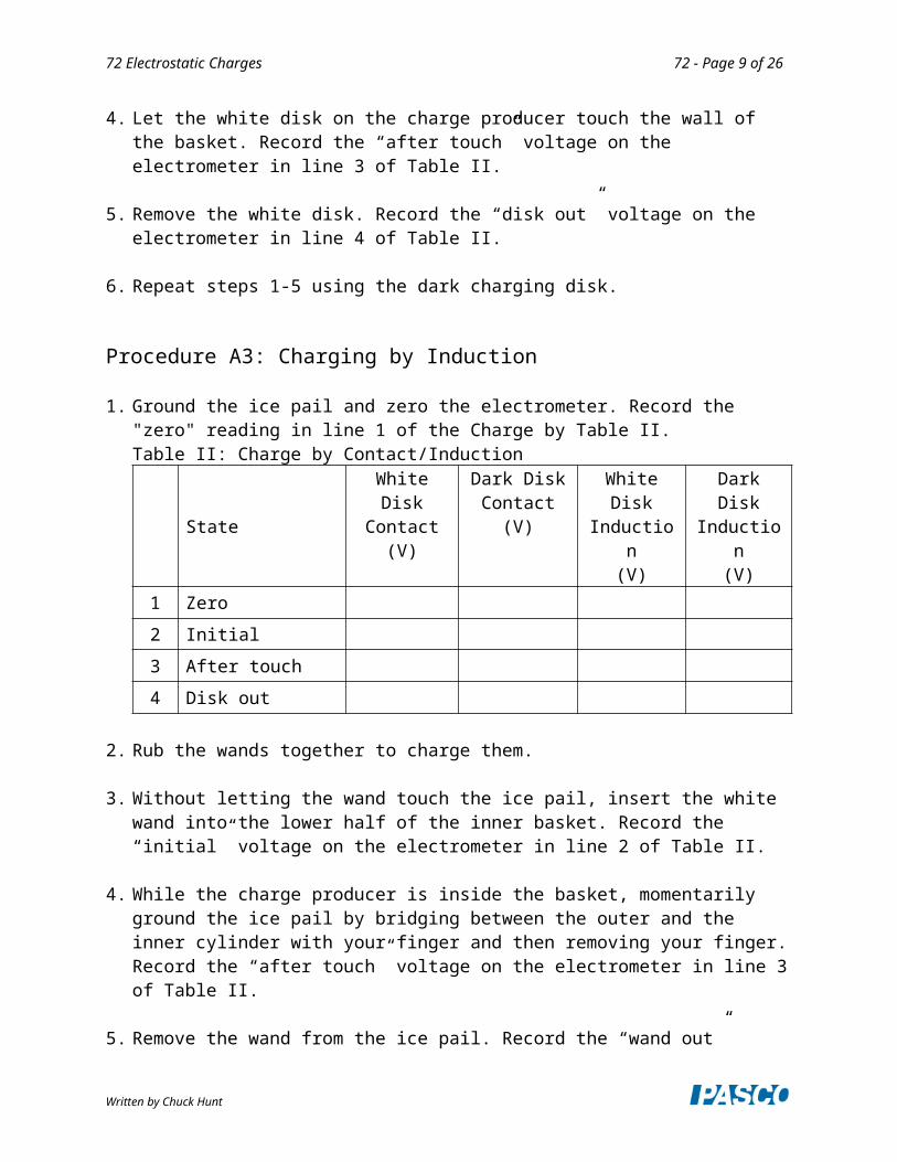
1. Ground the ice pail and zero the electrometer. Record the "zero" reading in line 1 of the Charge by Table II.Table II: Charge by Contact/Induction
StateWhite Disk
Contact(V)
Dark DiskContact
(V)
White DiskInduction
(V)
Dark DiskInduction
(V)1 Zero
2 Initial
3 After touch
4 Disk out
2. Rub the wands together to charge them.
3. Without letting the wand touch the ice pail, insert the white wand into the lower half of the inner basket. Record the “initial” voltage on the electrometer in line 2 of Table II.
4. While the charge producer is inside the basket, momentarily ground the ice pail by bridging between the outer and the inner cylinder with your finger and then removing your finger. Record the “after touch” voltage on the electrometer in line 3 of Table II.
5. Remove the wand from the ice pail. Record the “wand out” voltage on the electrometer in line 4 of Table II.
6. Repeat steps 1-5 using the dark charge producer.
Written by Chuck Hunt
72 Electrostatic Charges 72 - Page 8 of 16
Analysis A2/A3
1. What can you conclude from the data in the 2nd and 3rd columns (contact data) in the table?
2. Explain what is happening when you induce a charge on the inner mesh cylinder. That is, explain the data in columns 3 & 4 of the table. Why does the sign change?
Theory B
Charge Distribution on a Conducting Surface: charge will tend to concentrate at places on a conductor where the surface is more sharply curved. This happens because charges do not interact as strongly with other charges that are “over the horizon” since the electric field lines cannot pass through a conductor.
Charge inside a Spherical Conducting Shell: if the force between two point charges obeys an inverse square law (i.e. falls off like 1/r2), then all the charge on a conducting spherical shell must lie on the outside of the shell and the inside of the shell must be uncharged. Although we check this crudely here, it is possible to verify this with great precision and it is currently know that the exponent is 2 to within better than 1 part in 1030!
Procedure B1: Measuring the Charge at Different Locations on the Outer Surface of a Spherical Conductor
1. Plug in the Electrostatics Voltage Source and turn it on. Attach a black lead from the Common (Com) jack to a convenient ground like a water pipe or the silver outside connectors of the #2 or #3 outputs on the 850 Universal Interface. Attach the red lead to the +3000 V terminal and leave the spade connector on one end of the red lead unattached. P.S. you cannot get shocked by this power supply since it can only produce a tiny current.
2. Ground the ice pail (the inner cylindrical wire mesh) with your finger as before. Turn on the Electrometer, set it to the 30V range, and zero the electrometer.
3. The “proof plane” is the metal disk (silver looking) on one of the black wands. It is used for sampling charge on a conductor by touching it to the surface of the conductor. The amount of charge that transfers to the proof plane is proportional to the surface charge density at the point of contact. Make sure there is no charge in the proof plane by inserting it into the inner mesh cylinder. The electrometer should read zero. If there is charge on the proof plane ground it by touching it to any ground or the outer mesh cylinder.
4. Place the spherical conductor (no hole) well away from other objects (including people) to prevent polarization effects. Nothing should be closer to the sphere than the base on which it sits. The Faraday Ice Pail should also be well away from the sphere. You should perform the following steps as rapidly as possible to prevent significant discharge of the sphere though the air.
5. Briefly touch the free end of the red lead (the spade lug) to the spherical conductor (without a hole). This will charge the conductor to an electric potential of 3000V.
Written by Chuck Hunt
72 Electrostatic Charges 72 - Page 9 of 16
6. Touch the sphere at point A (see Figure 3) with the proof plane keeping your hands far away as possible.
7. Put the proof plane in the inner cylinder of the “ice pail” and record the voltage from the electrometer on Figure 3 at point A. Do not ground the proof plane so the total charge on the sphere and proof plane remains constant.
8. Repeat for points B & C.
Figure 3: Charge Distribution on a Sphere
Analysis B1:
Recall that the voltages recorded on Figure 3 are not the voltages on the sphere (the sphere is at a uniform 3000 V). They are the voltages between the inner and outer mesh cylinders with the proof plane inside the inner cylinder, which is directly proportional to the charge on the proof plane. What can you conclude about the distribution of charge on the sphere?
Procedure B2: Charging the Spherical Conductor to Different Potentials.
1. Same setup as in Procedure B1.
2. Ground the ice pail. Set the electrometer to the 10 V range and zero the electrometer. Make sure there is no charge in the proof plane. The electrometer should read zero. Repeat this anytime the electrometer does not read zero with nothing in the ice pail.
3. With one end of the red lead in the +1000 V terminal of the Electrostatics Voltage Source, touch the other end briefly to the surface of the conducting sphere.
4. Touch the top of the sphere with the proof plane.
Written by Chuck Hunt

72 Electrostatic Charges 72 - Page 10 of 16
5. Without letting it touch the basket, insert the proof plane into the lower half of the inner basket of the ice pail. Record the electrometer voltage in the second column of Table III.
Table III: Voltage vs. Charge on a SphereSphere Potential
(V)Electrometer Reading
(V)1000
2000
3000
6. Ground the proof plane. Make sure there is no residual charge in the proof plane before continuing.
7. Repeat the measurement for the +2000 V and +3000 V outputs (still on the 10 V range). If the reading is 9.9 V, you have exceeded the range. In that case, change the electrometer to the 30 V range, ground the ice pail, zero the electrometer and proceed.
Analysis B2
Recall that the electrometer voltages are the voltages between the inner and outer mesh cylinders with the proof plane inside the inner cylinder, which is directly proportional to the charge on the proof plane. What can you conclude about the charge on the sphere vs the electric potential (voltage) of the sphere?
Procedure B3: Measuring the Charge on the Outer Surface of a Non-Spherical Conductor
1. Same setup as Procedure B1 except replace the sphere with the non-spherical conductor. Use the +3000 V terminal on the Voltage Source. Electrometer on the 30 V range.
2. Ground the ice pail, zero the electrometer and make sure there is no charge in the proof plane. The electrometer should read zero.
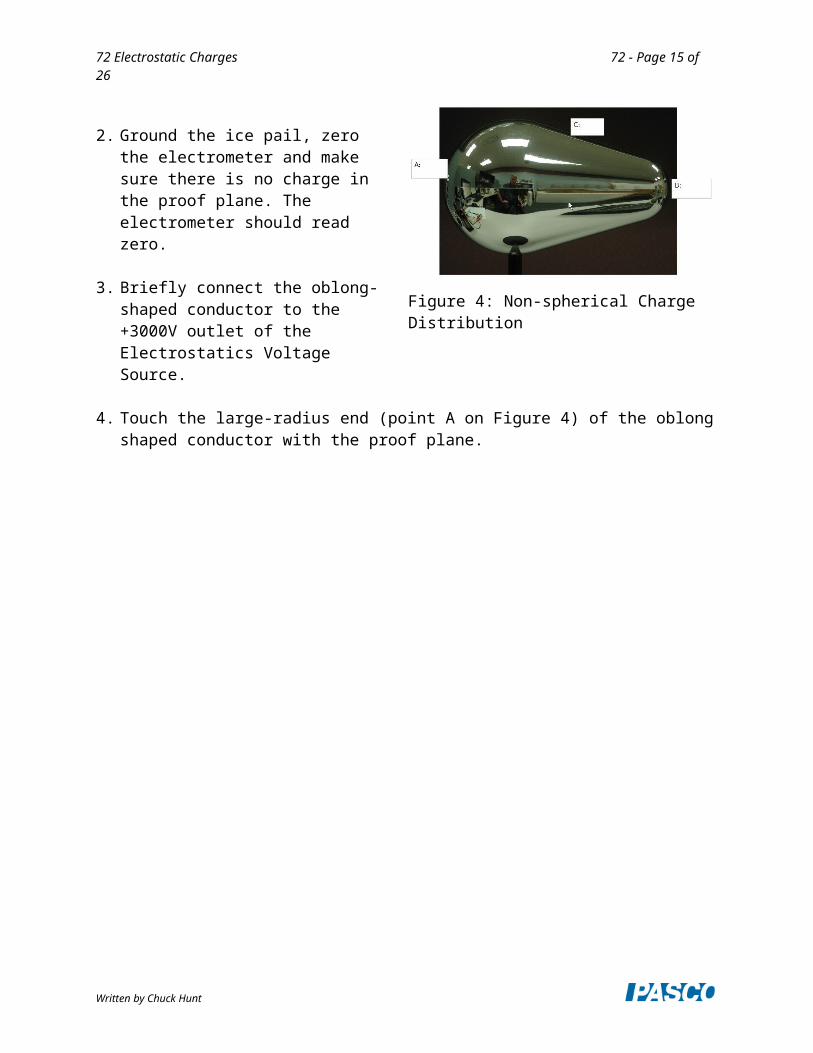
3. Briefly connect the oblong-shaped conductor to the +3000V outlet of the Electrostatics Voltage Source.
4. Touch the large-radius end (point A on Figure 4) of the oblong shaped conductor with the proof plane.
Written by Chuck Hunt
Figure 4: Non-spherical Charge DistributionFigure 4: Non-spherical Charge DistributionFigure 4: Non-spherical Charge DistributionFigure 4: Non-spherical Charge DistributionFigure 4: Non-spherical Charge DistributionFigure 4: Non-spherical Charge DistributionFigure 4: Non-spherical Charge DistributionFigure 4: Non-spherical Charge DistributionFigure 4: Non-spherical Charge DistributionFigure 4: Non-spherical Charge DistributionFigure 4: Non-spherical Charge DistributionFigure 4: Non-spherical Charge DistributionFigure 4: Non-spherical Charge DistributionFigure 4: Non-spherical Charge DistributionFigure 4: Non-spherical Charge DistributionFigure 4: Non-spherical Charge DistributionFigure 4: Non-spherical Charge DistributionFigure 4: Non-spherical Charge DistributionFigure 4: Non-spherical Charge DistributionFigure 4: Non-spherical Charge DistributionFigure 4: Non-spherical Charge DistributionFigure 4: Non-spherical Charge DistributionFigure 4: Non-spherical Charge Distribution

72 Electrostatic Charges 72 - Page 11 of 16
5. Without letting it touch the basket, insert the proof plane into the lower half of the inner basket of the ice pail. Record the reading from the electrometer on Figure 4 at point A.
6. Repeat the process at points B & C. Do not ground the proof plane so the total charge remains constant.
Analysis B3
What can you conclude about the distribution of charge on a non-spherical conductor?
Procedure B4: Measuring the Charge on the Inner Surface of a Spherical Conductor
1. Same setup as Procedure B3 except replace the oblong conductor with the sphere with a hole on top.
2. Ground the ice pail, zero the electrometer and make sure there is no charge on the proof-plane wand. You need to make a decision here. You may use either the disk end of the proof plane or the ball end. The ball end was designed for this experiment. However, it picks up a smaller amount of charge than the disk does, so requires you to operate on the 3 V range of the electrometer. The problem is that it is very easy to charge the non-conducting parts of the wand and on the 3 V range these charges have a large impact, and it is very difficult to discharge them. If you can successfully ground the ball end so that the electrometer remains near zero when the uncharged ball is inserted in the inner cylinder, then the ball works fine. I prefer using the disk with the electrometer on the 30 V range. Little charges on the handle are then not so important. However, considerable care is required to insert the disk into the hole without touching the sphere, and there is a risk of charge transfer even if the disk just comes close to the edge of the hole without touching.
3. Briefly touch the end of the red lead (attached to the +3000 V terminal) to the conducting sphere.
4. Keeping the proof plane as far as possible from the edges of the hole, insert the uncharged proof plane into the charged sphere and touch the inner wall near the bottom. Remove the proof plane from the hole. If the proof plane touches the edge, start over.
Written by Chuck Hunt

72 Electrostatic Charges 72 - Page 12 of 16
5. Without letting it touch the basket, insert the proof plane into the lower half of the inner basket of the ice pail. Record the electrometer reading in the first line of Table IV.
Table IV: Sphere Voltages
Sphere with Hole Electrometer Voltage(V)
1 Inside
2 Inside near hole
3 Outside
4 Inside again
5 Outside again
6. Keeping the proof plane as far as possible from the edges of the hole, insert the uncharged proof plane into the charged sphere and touch the inner wall near the hole. Be careful that the wand does not touch the edge of the hole or you will put a charge on the wand. Remove the proof plane from the hole. If the proof plane touches the edge, start over.
7. Without letting it touch the basket, insert the proof plane into the lower half of the inner basket of the ice pail. Record the electrometer reading in the second line of Table IV.
8. Touch the proof plane to the outside of the sphere (anywhere) and repeat step 7, recording the value from the electrometer on line 3.
9. Without grounding it, insert the proof plane in the hole and touch the inner wall near the bottom. Repeat step 7, recording the value on line 4.
10. Touch the proof plane to the outside of the sphere (anywhere) and repeat step 7, recording the value from the electrometer on line 5. If lines 3 and 5 are nearly equal and around 10 V, your data is probably OK. Variations of ± 1 V are probably not significant.
Analysis B4
1. What does the data in the table tell you about the distribution of charge on a hollow spherical shell?
2. Explain what happened in line 4 of Table IV.
Written by Chuck Hunt

72 Electrostatic Charges 72 - Page 13 of 16
Lab Report: Electrostatic ChargesName: ________________________________________________________________
Note: The answers to the fill-in-the-blanks questions are about the registers polarity of the electrometer. Answer ‘Positive,’ ‘Negative,’ or ‘Zero.’
OBSERVATIONS PROCEDURE A: Charging by Rubbing Objects Together
While rubbing the two charge producers together inside the basket:
The charge detected is __________.
After rubbing, with wands still in the basket, but not touching:
The charge detected is __________.
After removing the dark wand from the basket:
The charge detected on the white wand alone is __________.
The charge detected on the dark wand alone is __________.
QUESTIONS PROCEDURE A:
1. While the two wands were being rubbed against each other, what was their overall net charge?
2. After the rubbing process, what was the net overall charge of the two wands?
Written by Chuck Hunt

72 Electrostatic Charges 72 - Page 14 of 16
3. What is the evidence that the rubbing process gave each wand an electric charge?
4. What is the polarity of the white charge producer after rubbing it with the dark one? Did the white wand gain or did it lose electrons during the rubbing process? Where did the electrons go (or come from)?
5. What is the polarity of the dark charge producer after rubbing with the white one? Did the dark wand gain or did it lose electrons during the rubbing process? Where did the electrons go (or come from)?
6. Explain how this experiment demonstrates the law of conservation of charge.
Written by Chuck Hunt
72 Electrostatic Charges 72 - Page 15 of 16
OBSERVATIONS PROCEDURE B:Charging by Contact
After placing the white charge producer the inner basket:
The charge detected is ___________________.
After letting the charge producer touch the wall of the basket:
The charge detected is ___________________.
After inserting the dark charge producer into the inner basket and letting it touch the basket:
The charge detected is ___________________.
QUESTIONS PROCEDURE B:
1. Before the white wand touched the basket, what was the polarity of the white wand? What was the state of the basket?
2. After the white wand touched the basket, what was the polarity of the basket? Did the basket gain or lose electrons during the contact with the white wand? Where did the electrons go (or come from)?
3. After the dark wand touched the basket, what was the polarity of the basket? Did the basket gain or lose electrons during the contact with the dark wand? Where did the electrons go (or come from)?
4. When a charged object touches an initially neutral object, the neutral object acquires a charge. How does the polarity acquired by the initially neutral object compare to the polarity of the charged object that touched it?
Written by Chuck Hunt
72 Electrostatic Charges 72 - Page 16 of 16
OBSERVATIONS PROCEDURE C:Charging by Induction
Without letting the wand touch the ice pail:
The polarity of the charge on the white wand is _________________.
After grounding the ice pail and removing the wand:
The polarity of the charge on the pail is ___________________.
Repetition with the dark charge producer:
The polarity of the charge on the dark wand is _________________.
After the, the polarity of the charge on the pail is _______________.
QUESTIONS PROCEDURE C: 1. At the end of the process, how does the charge acquired by the pail compare to the polarity of the
charge on the wand that was used?
2. When using the white wand: Did the ice pail gain or lose electrons during the charging by induction process? Where did the electrons go (or come from)?
3. When using the dark wand: Did the ice pail gain or lose electrons during the charging by induction process? Where did the electrons go (or come from)?
Written by Chuck Hunt