Weather Protected Sunset Switch - Clipsal · Step 3: Set the Lux setting to 500 lux maximum (fully...
12
Installation Instructions Weather Protected Sunset Switch 31VSSR Series WS226SSR Series 56SSR Series
Transcript of Weather Protected Sunset Switch - Clipsal · Step 3: Set the Lux setting to 500 lux maximum (fully...

Installation Instructions
Weather Protected Sunset Switch
31VSSR Series WS226SSR Series
56SSR Series

31VSSR, WS226SSR & 56SSR Series Weather Protected Sunset Switch Installation Instructions
2 of 12 © 2011 Schneider Electric
Contents
1.0 Product Range.......................................................................................................................... 3
2.0 Description ............................................................................................................................... 3
3.0 Features .................................................................................................................................... 4
4.0 Operation .................................................................................................................................. 4
5.0 Installer Adjustable Settings .................................................................................................. 5
5.1 Timer Setting ..................................................................................................................... 5
5.2 Lux Setting ......................................................................................................................... 5
6.0 Test Mode ................................................................................................................................. 5
7.0 Switching Hysteresis ............................................................................................................... 6
8.0 Power-Up Sequence................................................................................................................. 6
9.0 Installation ................................................................................................................................ 7
10.0 Important Warning ................................................................................................................... 7
11.0 Wiring Diagrams – Two-Wire Designs .................................................................................... 8
11.1 Automatic Operation .......................................................................................................... 8
11.2 Automatic with Override OFF ............................................................................................ 8
11.3 Automatic with Override ON .............................................................................................. 8
11.4 ON / OFF / AUTO Operation (Override ON or OFF) .......................................................... 8
12.0 Wiring Diagrams – Three-Wire Designs ................................................................................. 9
12.1 Automatic Operation .......................................................................................................... 9
12.2 Automatic with Override OFF ............................................................................................ 9
12.3 Automatic with Override ON .............................................................................................. 9
12.4 ON / OFF / AUTO Operation (Override ON or OFF) .......................................................... 9
13.0 Special Loads ......................................................................................................................... 10
14.0 Electrical Specifications ........................................................................................................ 11
15.0 Warranty .................................................................................................................................. 12
31VSSR, WS226SSR & 56SSR Series Weather Protected Sunset Switch Installation Instructions
3 of 12© 2011 Schneider Electric
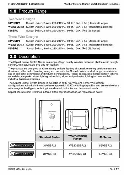
1.0 Product Range
Two-Wire Designs31VSSR/2 Sunset Switch, 2-Wire, 220-240Va, 50Hz, 10AX, IP56 (Standard Range)
WS226SSR/2 Sunset Switch, 2-Wire, 220-240Va, 50Hz, 10AX, IP66 (Weathershield Range)
56SSR/2 Sunset Switch, 2-Wire, 220-240Va, 50Hz, 10AX, IP66 (56 Series)
Three-Wire Designs31VSSR/3 Sunset Switch, 3-Wire, 220-240Va, 50Hz, 10AX, IP56 (Standard Range)
WS226SSR/3 Sunset Switch, 3-Wire, 220-240Va, 50Hz, 10AX, IP66 (Weathershield Range)
56SSR/3 Sunset Switch, 3-Wire, 220-240Va, 50Hz, 10AX, IP66 (56 Series)
2.0 DescriptionThe Clipsal Sunset Switch Series is a range of high quality, weather protected photoelectric daylight sensors, with adjustable time and lux facilities.
The products are designed to automatically activate lighting at sunset, ensuring outside areas are illuminated after dark. Providing safety and security, the Sunset Switch product range is suitable for use in domestic, commercial and industrial installations. Typical applications include garden lighting, verandahs, car parks, street lighting, advertising signs and perimeter lighting for commercial / industrial business premises.
The Clipsal Sunset Switch Range is available in both Two-Wire and Three-Wire design configurations. All units in the range have a powerful 10AX switching capability, and are suitable for a wide range of load types, including incandescent, inductive and fluorescent loads.
Clipsal offers Sunset Switches in three different product series, as represented below:
Standard Series Weathershield Range 56 Series
31VSSR/2 WS226SSR/2 56VSSR/2
31VSSR/3 WS226SSR/3 56VSSR/3

31VSSR, WS226SSR & 56SSR Series Weather Protected Sunset Switch Installation Instructions
4 of 12 © 2011 Schneider Electric
3.0 Features• State-of-the-art low current consumption Two and Three Wire designs• Adjustable Time Setting selection• Adjustable Lux Setting selection• 10AX switch load rating• Suitable for a wide range of load types:
� Incandescent (tungsten filament) lamps� 240V halogen / dichroic Lamps� Low voltage downlights using electronic transformers� Low voltage downlights using iron-core transformers� Fluorescent lighting loads*� Compact fluorescent light loads*� LED lighting loads*� Small motor loads (limited to 2A)
• Suitable for new installations or retro-fit applications• Complies with Australian and International Standards
* Two-Wire devices may require power factor correction capacitors to be fitted, else otherwise a 31CAP Load Correction Device to be installed to ensure correct operation. Refer to the “Special Loads” section of this instruction manual for more information.
4.0 OperationA Sunset Switch operates lighting loads automatically after dark, when the ambient light fades below a pre-determined level. Lights turn ‘ON’ automatically at Dusk and remain on until the pre-set timer period has elapsed or until Dawn (whichever occurs first).
Both Time and Lux settings are installer adjustable, and can be set to suit the specific application.
No adjustment is required to suit the seasons.
DD
56SSR / 2SUNSET SWITCH2 WIRE220-240V~50Hz 10AX µ
LOOP LOOP A/L LOAD
2H
4H 6H
8H
Test 20 500Lux DD
56SSR / 3SUNSET SWITCH3 WIRE220-240V~50Hz 10AX µ
LOOP N A/L LOAD
2H
4H 6H
8H
Test 20 500Lux
SWITCHING DELAY TIME APPROXIMATELY 90 SECONDS
(2-Wire Base) (3-Wire Base)

31VSSR, WS226SSR & 56SSR Series Weather Protected Sunset Switch Installation Instructions
5 of 12© 2011 Schneider Electric
20 500Lux
DD
2H
4H 6H
8H
Test
5.0 Installer Adjustable Settings
5.1 Timer SettingClipsal Sunset Switches incorporate an installer adjustable Timer Setting. The load will be activated for the preset period of time. Simply set the multi-position switch to the desired setting.
6.0 Test ModeA special “Test Mode” has been provided to enable the installer to set the current ambient light level as the ON switching threshold (Dusk setting).
In Test Mode the Switching Hysteresis time delay is disabled, allowing you to “seek” the current light level, without needing to wait for the normal switching delay time.
5.2 Lux SettingClipsal Sunset Switches incorporate an installer adjustable Lux Setting. The load will be switched according to the ambient light threshold set. Simply rotate the potentiometer to the desired setting.
*Note: If you overshoot the required setting, simply return the lux dial to maximum and repeat.For two-wire versions, you must wait at maximum lux until the load turns ON (max. 10 seconds) before re-trying.
WARNING:EXERCISE EXTREME CARE WHEN WORKING WITH THE LIVE PRODUCT.
Note: The factory default setting of approximately 20 lux will suffice for most applications.
Symbol Meaning Switching ConditionsDD Dusk to Dawn ON: The load with switch ON at Dusk.
OFF: The load with switch OFF at Dawn.2H 2 Hours ON: The load with switch ON at Dusk.
OFF: The load with switch OFF after the preset time has elapsed, OR at Dawn (whichever comes first).
4H 4 Hours6H 6 Hours8H 8 HoursTest TEST MODE Sets the light switching threshold to the current ambient light level.
Refer to Section 6.0: Test Mode for more information.
ADJUSTABLE RANGE: 20 to 500 lux
Step 1: Wire up the product and connect the load. Apply power.Step 2: Set the Timer to “Test” mode.Step 3: Set the Lux setting to 500 lux maximum (fully clockwise). The load will be ON.Step 4: Wait until the ambient light level reaches the desired switching threshold.Step 5: Turn the lux dial slowly anticlockwise until the load switches OFF*.Step 6: Exit Test Mode by setting the desired Timer Setting (DD, 2H, 4H, 6H, 8H).

31VSSR, WS226SSR & 56SSR Series Weather Protected Sunset Switch Installation Instructions
6 of 12 © 2011 Schneider Electric
7.0 Switching HysteresisClipsal Sunset Switches incorporate switching hysteresis, designed to ensure reliable operation of the product. Switching hysteresis is essentially an offset between the ON and OFF switching thresholds, making the product more immune to rapid fluctuations in the ambient lighting levels, and consequently less likely to false trigger.
8.0 Power-Up SequenceWhen power is applied for the first time, or re-applied after a power failure / lamp replacement, the Sunset Switch will remain idle for a short period (Warm-Up Time). During this period, the load will not be turned on, even if the ambient light level is below the switching threshold.
Example applications where rapid fluctuations in the ambient light level may be experienced:
• Dim light due to passing cloud cover• Lightning during a storm• Light from the headlamps of passing cars• Artificial light from the switched load
The switching hysteresis feature also intentionally introduces a Switching Delay Time of approximately 90 seconds.
During this time, the Sunset Switch continuously monitors the ambient light level in order to validate the transition from light to dark, or dark to light conditions. This reduces the risk of false
triggering due to momentary fluctuations in the ambient light levels.
Note: If power is interrupted during an active timer period, then the timer will be restarted upon restoration of power.
Type Models Warm-Up TimeTwo Wire Designs 31VSSR/2
WS226SSR/2 56SSR/2
3.5 minutes (approx)
Three-Wire Designs 31VSSR/3 WS226SSR/3 56SSR/3
90 seconds (approx)

31VSSR, WS226SSR & 56SSR Series Weather Protected Sunset Switch Installation Instructions
7 of 12© 2011 Schneider Electric
9.0 InstallationThe Sunset Switch may be positioned on any exterior surface facing away from any direct artificial light. Most light we see is reflected light. Accordingly, the Sunset Switch unit should be positioned so that it is NOT exposed to direct sunlight. Prolonged exposure to an ambient temperature exceeding the specified range may degrade the performance of the product.
The Sunset Switch must be installed in such a way that artificial light (such as the load that is being switched) has no impact on the operation. If the Sunset Switch is installed too close to the load being switched, then the load may turn on and off repeatedly.
Even when operating interior lights, it is recommended that the Sunset Switch is still positioned outside. It is also suggested that the unit is positioned out of normal reach to avoid shadows and other likely sources of interference with the sensor operation.
The unit should be mounted using the gaskets supplied. If the unit is to be mounted in an exposed position, all entries into the mounting box should be sealed with a silicone sealant.
Sunset Switch Mounting Accessories:
10.0 Important WarningIt is illegal for persons other than an appropriately licenced electrical contractor or other persons authorised by legislation to work on the fixed wiring of any electrical installation. Penalties for conviction are severe!
*Note that the WS226SSR Series Sunset Switch is compatible for mounting on many commonly available backboxes, including HPM 170 Series backboxes. Separate mounting screws with a
different thread type are provided to enable field retro-fit to the HPM backboxes.
Series Models Mounting Accessories31VSSR 31VSSR/2
31VSSR/3• 238 Backbox • Mounting Gasket • Mounting Screws • Screw Caps
WS226SSR WS226SSR/2 WS226SSR/3
• WS226 Backbox • Mounting Screws* • Screw Caps • Test Cover
56SSR 56SSR/2 56SSR/3
• 56ES1 Backbox • Mounting Screws • Screw Caps
31VSSR, WS226SSR & 56SSR Series Weather Protected Sunset Switch Installation Instructions
8 of 12 © 2011 Schneider Electric
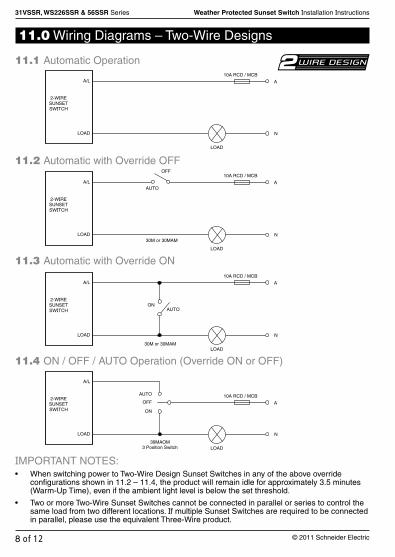
11.0 Wiring Diagrams – Two-Wire Designs
11.1 Automatic Operation
IMPORTANT NOTES:• When switching power to Two-Wire Design Sunset Switches in any of the above override
configurations shown in 11.2 – 11.4, the product will remain idle for approximately 3.5 minutes (Warm-Up Time), even if the ambient light level is below the set threshold.
• Two or more Two-Wire Sunset Switches cannot be connected in parallel or series to control the same load from two different locations. If multiple Sunset Switches are required to be connected in parallel, please use the equivalent Three-Wire product.
11.2 Automatic with Override OFF
11.3 Automatic with Override ON
11.4 ON / OFF / AUTO Operation (Override ON or OFF)
LOAD
10A RCD / MCB
A
N
A/L
LOAD
LOAD
10A RCD / MCB
A
N
A/L
LOAD
AUTO
OFF
30M or 30MAM
LOAD
10A RCD / MCB
A
N
A/L
LOAD
ON AUTO
30M or 30MAM
LOAD
10A RCD / MCB
A
N
A/L
LOAD
OFF
AUTO
ON
39MAOM 3 Position Switch
2-WIRE SUNSET SWITCH
2-WIRE SUNSET SWITCH
2-WIRE SUNSET SWITCH
2-WIRE SUNSET SWITCH
31VSSR, WS226SSR & 56SSR Series Weather Protected Sunset Switch Installation Instructions
9 of 12© 2011 Schneider Electric
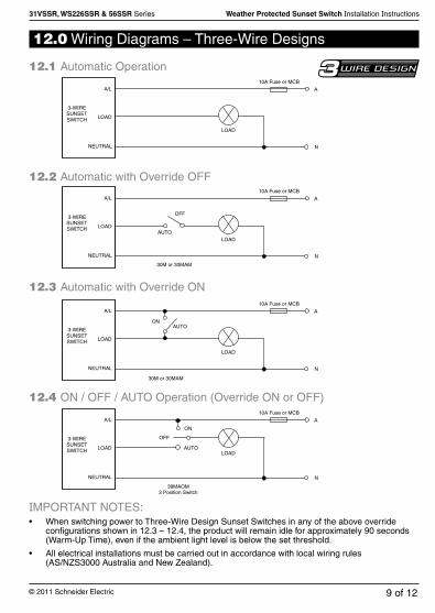
12.0 Wiring Diagrams – Three-Wire Designs
12.1 Automatic Operation
IMPORTANT NOTES:• When switching power to Three-Wire Design Sunset Switches in any of the above override
configurations shown in 12.3 – 12.4, the product will remain idle for approximately 90 seconds (Warm-Up Time), even if the ambient light level is below the set threshold.
• All electrical installations must be carried out in accordance with local wiring rules (AS/NZS3000 Australia and New Zealand).
12.2 Automatic with Override OFF
12.3 Automatic with Override ON
12.4 ON / OFF / AUTO Operation (Override ON or OFF)
LOAD
10A Fuse or MCB
A
N
A/L
LOAD
NEUTRAL
LOAD
10A Fuse or MCB
A
N
A/L
LOAD
NEUTRAL
AUTO
OFF
30M or 30MAM
LOAD
10A Fuse or MCB
A
N
A/L
LOAD
NEUTRAL
ON AUTO
30M or 30MAM
3-WIRE SUNSET SWITCH
3-WIRE SUNSET SWITCH
3-WIRE SUNSET SWITCH
3-WIRE SUNSET SWITCH LOAD
10A Fuse or MCB
A
N
A/L
LOAD
OFF
AUTO
ON
39MAOM 3 Position Switch
NEUTRAL

31VSSR, WS226SSR & 56SSR Series Weather Protected Sunset Switch Installation Instructions
10 of 12 © 2011 Schneider Electric
13.0 Special Loads
Product SelectionBe sure to select the appropriate product to suit your application:
• The 31VSSR/2, WS226SSR/2 and 56SSR/2 Sunset Switches are Two-Wire devices. These products do not require a Neutral connection, but can only switch a limited range of load types without special consideration.
• The 31VSSR/3, WS226SSR/3 and 56SSR/3 Sunset Switches are Three-Wire devices. These products require a Neutral connection to operate, and are capable of switching a wide range of load types.
*Please refer to Electrical Specifications for further information about compatible load types.
Handling Special Loads with Two-Wire DevicesTwo-Wire devices draw their power through the load. If a Two-Wire device is used in conjunction with a load which cannot provide enough continuous load current in the off-state, or the load is sensitive to a high off-state leakage current, then occasionally unexpected operation may result. Ultimate success depends upon the compatibility of the load type, and may vary depending on the make / model of the load.
In case abnormal operation is experienced, a 31CAP Load Correction Device fitted in parallel with the load may help to resolve the situation. Success varies from manufacturer to manufacturer. It is recommended to thoroughly test during installation. Installation must be compliant with local wiring rules.
Catalogue Number
Neutral Required
Minimum Load*
Maximum Load*
31CAP Req’d for some
Load Types
31VSSR/2 WS226SSR/2
56SSR/2NO 5W 10AX YES
31VSSR/3 WS226SSR/3
56SSR/3YES 0W 10AX NO
Line
Neutral
LineSunsetSwitch Load
31CAP
31CAP Load Correction Device
Load
Affected Load Type Example Load Typical Symptoms
• Small loads (<20W)• Loads which are sensitive to
leakage currents
• Non-Dimmable Compact Fluorescent Lamps (CFL’s)
• LED Lighting Drivers• Small (non power factor
corrected) Fluorescent Fittings• Single Relay or Contactor
• Unstable off-state operation (including lamp flicker)
• Relay chatter

31VSSR, WS226SSR & 56SSR Series Weather Protected Sunset Switch Installation Instructions
11 of 12© 2011 Schneider Electric
14.0 Electrical Specifications
Parameter
31VSSR/2WS226SSR/2
56SSR/2
31VSSR/3WS226SSR/3
56SSR/3
Nominal Operating Voltage 220 – 240VaNominal Operating Frequency 50HzMaximum Load Current 10AXMinimum Load 5W 0WMaximum Off-State Leakage Current
10mA 20mA
Compatible Loads*
*For Two-Wire Design Sunset Switches, certain loads may require special handling (Power Factor Correction Capacitor or 31CAP to be fitted). Refer “Special Loads” section.
• Incandescent Loads• MV Halogen Loads• Iron Core LV Lighting Transformers (EI and Toroidal Types)• Electronic LV Lighting Transformers• Linear Fluorescent Ballasts• Compact Fluorescent Loads• LED Lighting Drivers• HID Lamps (HPS, MH Lamps)• Small Motor Loads (2A max.)
Adjustable Lux Switching Threshold
Approximately 20 - 500 lux
Adjustable Timer Range Dusk till Dawn, 2H, 4H, 6H, 8HTimer Accuracy ± 10%Warm-Up Time 3.5 minutes 90 secondsInternational Protection Rating 31VSSR Series : IP56
WS226SSR Series : IP66 56SSR Series : IP66
Operating Temperature Range 0 to 45°COperating Humidity Range 10 to 95% R.H.Safety Compliances AS/NZS3100, AS/NZS3133, IEC60669-2-1EMC Emission Compliance AS/NZS CIRSPR14, CISPR15
Specifications Typical @ 240Va 25°CNo User Serviceable Parts Inside
WARNING:• Operation outside of these specifications may result in unexpected behaviour, or even
product failure.
• Timer accuracy may be affected by voltage, temperature and humidity.
• Warranty may be voided when controlling any incompatible load types as determined by Schneider Electric (Australia) Pty Ltd.

F2299/01 CLIPCOM 23617 September 2011
Schneider Electric (Australia) Pty Ltd
Contact us: clipsal.com/feedback
National Customer Care Enquiries:
Tel 1300 2025 25 Fax 1300 2025 56Schneider Electric (Australia) Pty Ltd reserves the right to change specifications, modify designs and discontinue items without incurring obligation and whilst every effort is made to ensure that descriptions, specifications and other information in this catalogue are correct, no warranty is given in respect thereof and the company shall not be liable for any error therein.
© 2011 Schneider Electric. All Rights Reserved.Trademarks are owned by Schneider Electric Industries SAS or its affiliated companies.
15.0 Warranty1. This Clipsal product is guaranteed against faulty workmanship and materials for a period of
two (2) years from the date of installation.
2. This warranty is expressly subject to the Clipsal product being installed, wired, tested, operated and used in accordance with the manufacturer’s instructions.
3. The warrantor is Schneider Electric (Australia) Pty Ltd of 33-37 Port Wakefield Road, Gepps Cross, South Australia 5094. With registered offices in all Australian States.
4. Schneider Electric (Australia) Pty Ltd reserves the right, at its discretion, to either repair free of parts and labour charges, replace or offer refund in respect to any article found to be faulty due to materials, parts or workmanship.
5. All costs of a claim shall be met by Schneider Electric (Australia) Pty Ltd, however should the product that is the subject of the claim be found to be in good working order all such costs shall be met by the claimant.
6. When making a claim the consumer shall forward the Clipsal product to the nearest office of Clipsal by Schneider Electric with adequate particulars of the defect within 28 days of the fault occurring. The product should be returned securely packed, complete with details of the date and place of purchase, description of load, and circumstances of malfunction.
7. The benefits conferred herein are in addition to, and in no way shall be deemed to derogate; either expressly or by implication, any or all other rights and remedies in respect to the Clipsal product, which the consumer has under the Commonwealth Competition and Consumer Act or any other similar State or Territory Laws.
Copyright Notice
The concepts, products and designs described in this document are the subject of international patents, and protected by international law. © Copyright Schneider Electric (Australia) Pty Ltd. All rights reserved.
Trademarks
• Clipsal is a registered trademark of Schneider Electric (Australia) Pty Ltd.• Clipsal by Schneider Electric is a registered trademark of Schneider Electric (Australia) Pty Ltd.All other logos and trademarks are the property of their respective owners.
Disclaimer
Schneider Electric (Australia) Pty Ltd reserves the right to change specifications or designs described in this manual without notice and without obligation.