Warm – up # 5 C (0, –1) V (0, 2) V (0, –4) F (0, 4) F (0, –6)

WDC400 Series
Dual Condensate Conductivity Monitor
Instruction Manual
Five Boynton Road Hopping Brook Park Holliston, MA 01746 USA
TEL: 508-429-1110 FAX: 508-429-7433 WEB: www.walchem.com
WDC400 Controllers
W A L C H E M
IWAKI America Inc.

Notice
© 2013 WALCHEM, Iwaki America Inc.(hereinafter “Walchem”) 5 Boynton Road, Holliston, MA 01746 USA (508) 429-1110 All Rights Reserved Printed in USA
Proprietary Material
The information and descriptions contained herein are the property of WALCHEM. Such information and descriptions may not be copied or reproduced by any means, or disseminated or distributed without the express prior written permission of WALCHEM, 5 Boynton Road, Holliston, MA 01746. This document is for information purposes only and is subject to change without notice.
Statement of Limited Warranty
WALCHEM warrants equipment of its manufacture, and bearing its identification to be free from defects in workmanship and material for a period of 24 months for electronics and 12 months for mechanical parts from date of delivery from the factory or authorized distributor under normal use and service and otherwise when such equipment is used in accordance with instructions furnished by WALCHEMand for the purposes disclosed in writing at the time of purchase, if any. WALCHEM's liability under this warranty shall be limited to replacement or repair, F.O.B. Holliston, MA U.S.A. of any defective equipment or part which, having been returned to WALCHEM, transportation charges prepaid, has been inspected and determined by WALCHEM to be defective. Replaceable elastomeric parts and glass components are expendable and are not covered by any warranty. THIS WARRANTY IS IN LIEU OF ANY OTHER WARRANTY, EITHER EXPRESS OR IMPLIED, AS TO DESCRIPTION, QUALITY, MERCHANTABILITY, FITNESS FOR ANY PARTICULAR PURPOSE OR USE, OR ANY OTHER MATTER. 180333.J
April 2013

TABLE OF CONTENTS
1.0 IINTRODUCTION ............................................................................................................ 1
2.0 SPECIFICATIONS .......................................................................................................... 1 2.1 Measurement Performance .......................................................................................... 1 2.2 Electrical: Input/Output ................................................................................................. 1 2.3 Mechanical ................................................................................................................... 2 2.4 WDC Variables and their Limits .................................................................................... 2
3.0 UNPACKING & INSTALLATION .................................................................................... 3 3.1 Unpacking the unit ........................................................................................................ 3 3.2 Mounting the electronic enclosure ................................................................................ 3 3.3 Installation .................................................................................................................... 3 3.4 Icon Definitions ............................................................................................................. 3 3.5 Electrical installation ..................................................................................................... 4
4.0 FUNCTION OVERVIEW .................................................................................................. 8 4.1 Front Panel ................................................................................................................... 8 4.2 Display ......................................................................................................................... 8 4.3 Keypad ......................................................................................................................... 9 4.4 Access Code ................................................................................................................ 9 4.5 Startup ......................................................................................................................... 9 4.6 Shut Down .................................................................................................................. 10
5.0 OPERATION ................................................................................................................. 10 5.1 Main Menu ................................................................................................................. 10 5.2 Conductivity (A or B) Menu ......................................................................................... 12 5.3 Temperature (A or B) Menu ........................................................................................ 13 5.4 Divert (A or B) Menu ................................................................................................... 14 5.5 Time Menu ................................................................................................................. 15 5.6 4-20mA (A or B) Menu ................................................................................................ 16 5.7 Access Code Menu .................................................................................................... 17 5.8 Datalog Menu ............................................................................................................. 18 5.9 Config Menu ............................................................................................................... 20 5.10 Upgrade Menu ........................................................................................................ 21
6.0 MAINTENANCE ............................................................................................................ 22 6.1 Electrode Cleaning ..................................................................................................... 22 6.2 Replacing the Fuses ................................................................................................... 22
7.0 TROUBLESHOOTING .................................................................................................. 23 7.1 Error Messages .......................................................................................................... 23 7.2 Conductivity Readout Does Not Change .................................................................... 24 7.3 Procedure for Evaluation of Conductivity Electrode .................................................... 24 7.4 Procedure for checking relay outputs ...................................................................... 24
8.0 SERVICE POLICY ........................................................................................................ 25
1
1.0 IINTRODUCTION
The Walchem WDC400 Series monitors offer conductivity control of boiler condensate of two
separate boilers. If the conductivity rises above the set point, the controller will activate a diverter
valve to prevent the contaminated condensate from returning to the boiler and/or set off an alarm.
The WDC series condensate monitors are supplied with a temperature compensated electrode
with a cell constant of 1.0. The monitors are microprocessor driven industrial type with on/off
control outputs. One or two optional isolated 4-20 mA outputs that are proportional to the
conductivity reading are available for all models.
Any set point may be viewed without interrupting control. Each set point change will take effect
as soon as it is entered. An access code is available to protect set point parameters, while still
allowing settings to be viewed.
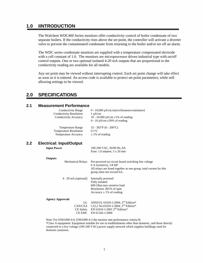
2.0 SPECIFICATIONS
2.1 Measurement Performance Conductivity Range 0 - 10,000 µS/cm (microSiemens/centimeter)
Conductivity Resolution 1 µS/cm
Conductivity Accuracy 10 - 10,000 µS/cm ±1% of reading
0 - 10 µS/cm ±20% of reading
Temperature Range 32 - 392°F (0 - 200°C)
Temperature Resolution 0.1°C
Temperature Accuracy ± 1% of reading
2.2 Electrical: Input/Output Input Power
100-240 VAC, 50/60 Hz, 8A
Fuse: 1.0 ampere, 5 x 20 mm
Outputs
Mechanical Relays Pre-powered on circuit board switching line voltage
6 A (resistive), 1/8 HP
All relays are fused together as one group, total current for this
group must not exceed 6A.
4 - 20 mA (optional) Internally powered
Fully isolated
600 Ohm max resistive load
Resolution .001% of span
Accuracy ± 1% of reading
Agency Approvals
UL ANSI/UL 61010-1:2004, 2nd Edition*
CAN/CSA C22,2 No.61010-1:2004, 2nd Edition*
CE Safety EN 61010-1:2001 2nd Edition*
CE EMC EN 61326-1:2006
Note: For EN61000-4-6, EN61000-4-3 the monitor met performance criteria B.
*Class A equipment: Equipment suitable for use in establishments other than domestic, and those directly
connected to a low voltage (100-240 VAC) power supply network which supplies buildings used for
domestic purposes.

2
2.3 Mechanical Enclosure Material Polycarbonate
NEMA Rating NEMA 4X
Dimensions 8.5" x 6.5" x 5.5"
Display 2 x 16 character backlit liquid crystal
Operating Ambient Temp 32 – 122°F (0 – 50°C)
Storage Temperature -20 – 180°F (-29 – 80°C)
Electrode mounting ¾" NPTF
Electrode rating 250 psi at 392°F (17.2 bars at 200°C)
Electrode material 316 SS and PEEK
2.4 WDC Variables and their Limits
Low Limit High Limit
Conductivity menu
PPM Conversion Factor 0.200 ppm/µS/cm 1.000 ppm/µS/cm
Interval Time (sampling) 5 minutes 24:00 hours
Duration Time (sampling) 1 minute 59 min: 59 sec
% Calibration Range -50 +50
Temperature Menu No variables
Divert Menu (set in hrs/minutes)
Set Point 0 µS/cm 10,000 µS/cm
Dead Band 5 µS/cm 500 µS/cm
Divert Time Limit 1 minute 8 hrs:20 min (enabled)
Unlimited (disabled)
4-20 mA Menus 4 & 20 mA Settings 0 µS/cm 10,000 µS/cm
Access Code Menu New Value 0 9999
Alarm Menu* High & Low (set to zero to disable) 1% 50%
Datalog Menu (Optional) No variables
Config Menu (Optional) No variables
Upgrade Menu No variables
*Note: The Alarm relay is non-programmable. Refer to the Main Menu diagram on page 16 for the list of error
conditions that trigger the alarm relay.
3
3.0 UNPACKING & INSTALLATION
3.1 Unpacking the unit
Inspect the contents of the carton. Please notify the carrier immediately if there are any signs of
damage to the controller or its parts. Contact your distributor if any of the parts are missing. The
carton should contain: a WDC300 series monitor and an instruction manual. Any options or
accessories will be incorporated as ordered.
3.2 Mounting the electronic enclosure
The WDC series monitor is supplied with mounting holes on the enclosure. It should be wall
mounted with the display at eye level, on a vibration-free surface, utilizing all four mounting
holes for maximum stability. Use M6 (1/4" diameter) fasteners that are appropriate for the
substrate material of the wall. The enclosure is NEMA 4X rated. The maximum operating
ambient temperature is 32 to 122°F (0 to 50°C); this should be considered if installation is in a
high temperature location. The enclosure requires the following clearances:
Top: 2" (50 mm)
Left: 8" (203 mm)
Right: 4" (102 mm)
Bottom: 7" (178 mm)
3.3 Installation
The conductivity electrodes should be placed as close to the monitor as possible, to a maximum
distance of 500 ft. Under 25 ft is recommended. Over 25 ft, the cable may need to be shielded
from background electrical noise. (The standard cable length is 10 feet. Should you require longer
cable, consult factory.)
Locate the electrode tees where an active sample of condensate water is available and where the
electrode can easily be removed for cleaning. They must be situated so that the tee is always full
and the electrode is never subjected to a drop in water level resulting in dryness. Refer to Figure 1
for typical installation.
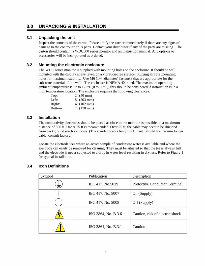
3.4 Icon Definitions
Symbol Publication Description
IEC 417, No.5019 Protective Conductor Terminal
IEC 417, No. 5007 On (Supply)
IEC 417, No. 5008 Off (Supply)
ISO 3864, No. B.3.6 Caution, risk of electric shock
ISO 3864, No. B.3.1 Caution

4
3.5 Electrical installation
The various standard wiring options are shown in Figure 2. Your WDC series monitor will arrive
from the factory prewired or ready for hardwiring. Depending on your configuration of options,
you may be required to hardwire some or all of the input/output devices. Refer to figures 3 and 4
for circuit board layout and wiring.
CAUTION
1. There are live circuits inside the monitor even when the power switch on the front panel is in
the OFF position! The front panel must never be opened before power to the monitor is
REMOVED!
If your monitor is prewired, it is supplied with a 8 foot, 18 AWG power cord with USA style
plug. A tool (#1 Phillips driver) is required to open the front panel.
2. When mounting the monitor, make sure there is clear access to the disconnecting device!
3. The electrical installation of the monitor must be done by trained personnel only and conform
to all applicable National, State and Local codes!
4. Proper grounding of this product is required. Any attempt to bypass the grounding will
compromise the safety of persons and property.
5. Operating this product in a manner not specified by Walchem may impair the protection
provided by the equipment.
POWER
ALARM A
DIVERT A
ALARM
CONDUCTIVITYELECTRODE A
4-20mA (2)(OPTIONAL)
ALARM B
DIVERT B PLUGFLOW
SWITCH B(OPTIONAL)
CONDUCTIVITYELECTRODE B
FLOWSWITCH A(OPTIONAL)
4-20mA (1)(OPTIONAL)
Figure 1 Conduit/Wiring Confguration

5
BOILERRECEIVER
TANK
TO DRAIN
CONDUCTIVITYELECTRODE
HEAT EXCHANGER
DIVERTER VALVE
BOILERRECEIVER
TANK
TO DRAIN
CONDUCTIVITYELECTRODE
HEAT EXCHANGER
DIVERTER VALVE
SYSTEM 1
SYSTEM 2
Dual Condensate Monitor
www.walchem.com
PREV NEXT
ENTER EXIT
Figure 2 Typical Installation

6
Power Supply(115 VAC or 230 VAC)
Contact Closure:Polarity not critical
Reed SwitchFlow Meter
Polarity not Critical
IN-
FLOW MTR 1 FLOW MTR 2
IN+
FLOW SW 1
IN+IN-IN+
+5VBLKRED
CONDT-T+
BLEED
N.C.
FEED
N.O. N.C. N.O.L2L2
L1 L2/N
Hall EffectFlow Meter
GR
EE
NW
HIT
E
GROUND STUD
SHIELD
L1 L2/N
GRN 120V
GRN/Y
EL 240V
WHT 120VBLU 240V
BLK
120V
BR
N 2
40V
R+
R-
+5
VB
LK
RE
DC
ON
DT
-T
+
R+
R-
ConductivityElectrode
Do not connectshield drain wire
at this end!G WR B
GR
EE
N
WH
ITE
SHIELD
ConductivityElectrode
Do not connectshield drain wire
at this end!G WR B
FLOW SW 2
IN-IN+
SYSTEM A
SYSTEM B
IN-
FLO
W M
TR
1F
LO
W M
TR
2
IN+
FL
OW
SW
1
IN+
IN-
IN+
FL
OW
SW
2
IN-
IN++5
VB
LK
RE
DC
ON
DT-
T+
+5VBLKRED
CONDT-T+
F1
F2
SYSTEM A SYSTEM B
Figure 3 Inputs

7
Alarm
DiverterValve
L1 L2/N
L2 L2 L2 L2 L2 L2BLEED
N.C. N.O. N.C.
BOI 1
N.O.N.C.
FEED
N.C.
BIO 2
N.O. N.C. N.O. N.O.
ALARM
N.C. N.O.
L2/N L2/N L2/N L2/N L2/N L2/NDIVERT A
N.C. N.O.DIVERT B
N.O.N.C.ALARM A
N.C.ALARM B
N.O. N.C. N.O.ALARM
N.C. N.O.
GROUNDSTUD
WH
T 1
20
VB
LU
240
V
GRN 120VGRN/YEL 240V
GRN 120VGRN/YEL 240V
IF MOTORIZEDBALL VALVE
BL
K 1
20V
BR
N 2
40
V
+5V
BL
KR
ED
CO
ND
T-
T+
ChartRecorder
BL
K 1
20
VB
RN
24
0V WHT 120V
BLU 240V
WH
T 1
20
VB
LU
24
0V
WH
T 1
20
VB
LU
24
0V
GRN 120VGRN/YEL 240VTO GROUND STUD
GRN 120VGRN/YEL 240VTO GROUND STUD
GRN 120VGRN/YEL 240VTO GROUND STUD
WH
T 1
20
VB
LU
24
0V
ChartRecorder
IN-
FLO
W M
TR
1F
LO
W M
TR
2
IN+
FLO
W S
W 1
IN+
IN-
IN+
FLO
W S
W 2
IN-
IN+
+5V
BLK
RE
D
CO
ND
T-
T+
Diverter Valve
IF M
OT
OR
IZE
DB
ALL V
ALV
E
BL
K 1
20
VB
RN
24
0V
BL
K 1
20
VB
RN
24
0V
BL
K 1
20
VB
RN
240
V
AlarmAlarmNOTE: When connecting amotorized ball valve, the pre-wired pigtail must be removed and thevalve requires two wires, one toN.O. to open the valve and one toN.C. to close the valve.
SYSTEM A SYSTEM B
Figure 4 Outputs
8
4.0 FUNCTION OVERVIEW
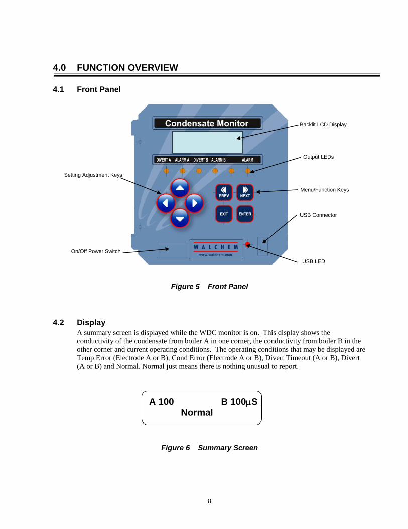
4.1 Front Panel
Figure 5 Front Panel
4.2 Display
A summary screen is displayed while the WDC monitor is on. This display shows the
conductivity of the condensate from boiler A in one corner, the conductivity from boiler B in the
other corner and current operating conditions. The operating conditions that may be displayed are
Temp Error (Electrode A or B), Cond Error (Electrode A or B), Divert Timeout (A or B), Divert
(A or B) and Normal. Normal just means there is nothing unusual to report.
A 100 B 100S Normal
Figure 6 Summary Screen
On/Off Power Switch
Backlit LCD Display
Output LEDs
Setting Adjustment Keys
Menu/Function Keys
USB Connector
USB LED

9
4.3 Keypad
The keypad consists of 4 directional arrow keys and 4 function keys. The arrows are used to move
the adjustment cursor and change settings, while the function keys are used to enter values, and
navigate the various menu screens. The function keys are ENTER, EXIT, NEXT, and PREV
(previous). NEXT and PREV scroll through the various menu choices. ENTER is used to enter a
submenu and to enter a value. EXIT is used to back up one menu level. If you are at the main
menu level, EXIT will return you to the Summary Display.
To change a value in a submenu, the left/right arrow keys move the cursor left and right to each
digit or option that can be changed. The up/down arrows will change numeric values up or down,
or scroll through option choices. Press ENTER only when you have finished making all of the
changes for that menu screen.
4.4 Access Code
The WDC series monitor is shipped with the access code disabled. If you wish to enable it, see
Section 5.6 for operation. With the access code enabled, any user can view parameter settings, but
not change them. Note that this provides protection only against casual tampering. Use a lock on
the cover latch if you need more protection.
4.5 Startup
Initial Startup After having mounted the enclosure and wired the unit, the monitor is ready to be started.
Plug in the monitor and turn on the power switch to supply power to the unit. The display will
briefly show the WDC model number and then revert to the normal summary display. Scroll
through the menus and calibrate the conductivity reading, temperature, and set the control
parameters detailed in Section 5, Operation.
To return to the summary display, press the EXIT key until you return to this screen. The
controller will automatically return to this screen after 10 minutes.
Normal Startup
Startup is a simple process once your set points are in memory. Simply check your supply of
chemicals, turn on the monitor, calibrate it if necessary and it will start controlling.

10
4.6 Shut Down
To shut the WDC monitor down, simply turn off the power. Programming remains in memory.
5.0 OPERATION
These units control continuously while power is applied. Programming is accomplished via the
local keypad and display.
To view the top level menu, press any key. The menu structure is grouped by inputs and outputs.
Each input has its own menu for calibration and unit selection as needed. Each output has its own
setup menu including set points, timer values and operating modes as needed. After ten minutes
of inactivity in the menu, the display will return to the summary display. Keep in mind that even
while browsing through menus, the unit is still controlling.
5.1 Main Menu
The exact configuration of your WDC monitor determines which menus are available as you
scroll through the settings. Certain menus are only available if you select certain options. All
settings are grouped under the following main menu items: Boiler A, Boiler B and Access Code.
Within the menu for each boiler, the following menus are found:
Main Menu Top Level
Boiler A
Boiler B
Time
Access Code
Datalog Only if advanced USB feature is in model code
Config Only if advanced USB feature is in model code
Upgrade
Inside Boiler A and B menus
Conductivity A or B
Temperature A or B
Divert A or B
4-20mA A or B Only if 4-20mA option board(s) installed.
The NEXT key travels forward through this list while the PREV key travels backwards through
the list. Pressing ENTER will Enter the lower level menu that is currently displayed.
Each of the following menu descriptions are used exactly the same way for either Boiler A or
Boiler B.

11
A
100
B 1
00
µs
B
oile
r A
A
10
0
B 1
00 µ
s
NO
RM
AL
Main
Men
u
Pre
ss E
nte
r ke
y t
o e
nte
r m
enu
.
Pre
ss E
xit k
ey t
o e
xit m
en
u.
Blin
kin
g fie
lds m
ay b
e e
dite
d w
ith
the
ad
just
arr
ow
s.
Op
era
tion
A
10
0
B
100
µs
B
oile
r B
A
100
B
10
0 µ
s
A
ccess C
ode
A:
10
00
µs
7
7°F
C
on
du
ctivity A
A
: 1
000
µs
7
7°F
Te
mp
era
ture
AA
: 1
000
µs
77
°F
Div
ert
A
A:
100
0 µ
s
7
7°F
4-2
0 m
A_
1 9
.32m
A
Sam
e a
s A
Only
ap
pe
ars
if
optio
nb
oa
rd is in
sta
lled
.
Legend
Po
ssib
le s
tatu
s s
cre
en
s
TE
MP
ER
R A
TE
MP
ER
R B
CO
ND
ER
R A
CO
ND
ER
R B
DIV
ER
T T
IME
OU
T A
NO
RM
AL
DIV
ER
T T
IME
OU
T B
DIV
ER
T A
DIV
ER
T B
A 10
0
B
100
µs
T
ime:S
un
3
:00
A 1
00
B
10
0 µ
s
Da
talo
gA
1
00
B 1
00 µ
s
C
on
fig
A
100
B 1
00 µ
s
U
pg
rad
e
Figure 7 Main Menu
12
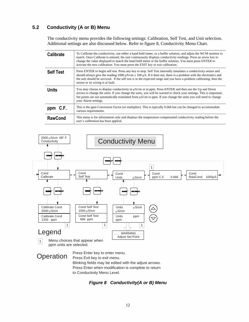
5.2 Conductivity (A or B) Menu
The conductivity menu provides the following settings: Calibration, Self Test, and Unit selection.
Additional settings are also discussed below. Refer to figure 8, Conductivity Menu Chart.
Calibrate To Calibrate the conductivity, use either a hand held meter, or a buffer solution, and adjust the WCM monitor to match. Once Calibrate is entered, the unit continuously displays conductivity readings. Press an arrow key to
change the value displayed to match the hand held meter or the buffer solution. You must press ENTER to
activate the new calibration. You must press the EXIT key to exit calibration.
Self Test Press ENTER to begin self test. Press any key to stop. Self Test internally simulates a conductivity sensor and
should always give the reading 1000 S/cm ± 100 S. If it does not, there is a problem with the electronics and
the unit should be serviced. If the self test is in the expected range and you have a problem calibrating, then the sensor or its wiring is at fault.
Units You may choose to display conductivity in S/cm or in ppm. Press ENTER and then use the Up and Down
arrows to change the units. If you change the units, you will be warned to check your settings. This is important.
Set points are not automatically translated from S/cm to ppm. If you change the units you will need to change your Alarm settings.
ppm C.F. This is the ppm Conversion Factor (or multiplier). This is typically 0.666 but can be changed to accommodate
various requirements.
RawCond This menu is for information only and displays the temperature-compensated conductivity reading before the user’s calibration has been applied.
Calibrate Cond
2000 S/cm
Cond Self Test
1000 S/cm
Cond Self Test 666 ppm
Units S/cm
S/cm
Units ppmppm
. . . . WARNING . . . .Adjust Set Point
CondCalibrate
2000 S/cm 68° FConductivity
CondSelf Test
Cond
Units S/cm
Condppm C.F. 0.666
Conductivity Menu
Menu choices that appear when ppm units are selected.
Press Enter key to enter menu.
Press Exit key to exit menu.
Blinking fields may be edited with the adjust arrows.
Press Enter when modification is complete to return
to Conductivity Menu Level.
Calibrate Cond1333 ppm
Legend
Operation
1
1 1 1
1
CondRawCond 1000µS
Figure 8 Conductivity(A or B) Menu

13
5.3 Temperature (A or B) Menu
The Temperature menu provides the following settings: Calibration, Unit selection. The
Temperature menu will be indicated on the display by one of the following:
Temperature Normal operation
Temp 70°F Normal operation
Temp Error Indicates that there is a problem with the temperature input. See Figure 9.
Calibrate This menu appears only if a temperature element is connected at power-up. To Calibrate the Temperature, use a thermometer to measure the fluid temperature and adjust the WDC monitor to match. Once Calibrate is entered, the
unit continuously displays temperature readings. Press the Up or Down arrow key to change the value displayed to
match the thermometer. You must press ENTER to activate the new calibration. You must press the EXIT key to exit calibration.
Man Temp This menu appears only if no temperature element is connected at power-up. Use the arrow keys to adjust the
temperature displayed to match that of the boiler water.
Units You may choose to display temperature in °C or °F. Press ENTER and the Up or Down Arrow keys to change the
temperature units for display.
Mode Press ENTER and use the UP or DOWN arrow keys to select between Manual Temperature Compensation (used
with sensors that do not have a temperature measuring element in them) or Automatic Temperature Compensation. If Automatic is selected, and the temperature element is not detected, the controller will display a Temp Error and
revert to Manual Temp Comp until the signal is restored.
Calibrate Temp °F 68
Units °F°F
Units °C°C
Temp 68°FCalibrate
Temp 68°F Man Temp 68
2000 s 68° FTemperature
Temp 68°FUnits °F
Temperature Menu
Menu wording that appears when Automatic Temperature Compensation is selected.
Legend
Menu wording that appears when Manual Temperature Compensation is selected.
Temperature Err
Possible Status Screen
Calibrate Temp °C 20.1
Mode ManManual Temp Comp
Mode ManAuto Temp Comp
Temp 68°FMode Manual
21
2
1
Figure 9 Temperature (A or B) Menu

14
5.4 Divert (A or B) Menu
The Divert Menu provides the following settings: Set Point, Dead Band, Control Direction,
HOA. The Divert menu will be indicated on the display by one of the following. The ‘A’
indicates that the output is being controlled automatically.
Divert A OFF Indicates that the divert output is currently OFF.
Divert A 10:00 Indicates the length of time that the Alarm output has been ON.
Divert A TIMEOUT Iindicates that the direct output has been ON longer than the programmed time limit.
Set Point This is the conductivity value at which the diverter valve output and alarm output are turned ON. The factory
default setting for the WDC monitor is for the divert and alarm outputs to turn on when the conductivity is higher than the set point. This may be changed at the Control Direction screen.
Dead Band This is the conductivity value that when combined with the set point determines when the alarm outputs turn
OFF. Assuming that the control direction is set for normal operation (High Set Point) the alarm outputs will turn
off when the conductivity drops below the set point minus the Dead Band. For example: The set point is 25
S/cm and the Dead Band is 5 S/cm. The alarm outputs turn ON when the conductivity reading is greater than
25 but does not turn OFF until the conductivity drops below 20.
Time Limit This menu allows you to set a maximum amount of time for the alarm. The limit time is programmed in hours and minutes and can be set between 1 minute and 8 hours, 59 minutes. If the time limit is set to zero, then the
valve may be open indefinitely. If the maximum time is exceeded, the diverter valve will close and will not
reopen until the "Reset Timer" menu is reset by an operator.
Reset Timer Only appears if the time limit above has been exceeded. Use the up or down arrow to change "N" to "Y", then press ENTER.
Control Dir H / L
This allows you to set the Normal (High Set Point) or Inverse (Low Set Point) operation of the outputs. When
set to High, the outputs turn on when the conductivity is higher than the set point. When set to Low, the outputs turn on when the conductivity is lower than the set point.
High Set Point Low Set Point
H O A The “Hand Off Auto” screen allows you to select the operating mode of the alarm outputs. In Hand (manual)
mode, the output is turned on immediately for a maximum of 10 minutes. If you walk away, the output will
return to Auto mode at the end of that time. In Off mode the output will stay Off indefinitely. In Auto mode the output will respond to changes in conductivity based on the set point. The HOA mode of the alarm output is
indicated on the alarm status lines.
Figure 10 Divert (A or B) Menu
15
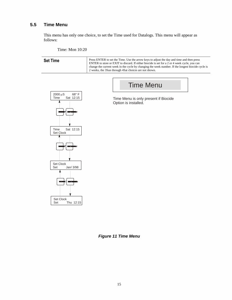
5.5 Time Menu
This menu has only one choice, to set the Time used for Datalogs. This menu will appear as
follows:
Time: Mon 10:20
Set Time Press ENTER to set the Time. Use the arrow keys to adjust the day and time and then press
ENTER to store or EXIT to discard. If either biocide is set for a 2 or 4 week cycle, you can change the current week in the cycle by changing the week number. If the longest biocide cycle is
2 weeks, the 3Sun through 4Sat choices are not shown.
2000 S 68° FTime Sat 12:15
Time Sat 12:15Set Clock
Set ClockSet Jan/ 3/98
Time Menu
Time Menu is only present if BiocideOption is installed.
Set ClockSet Thu 12:15
Figure 11 Time Menu
16
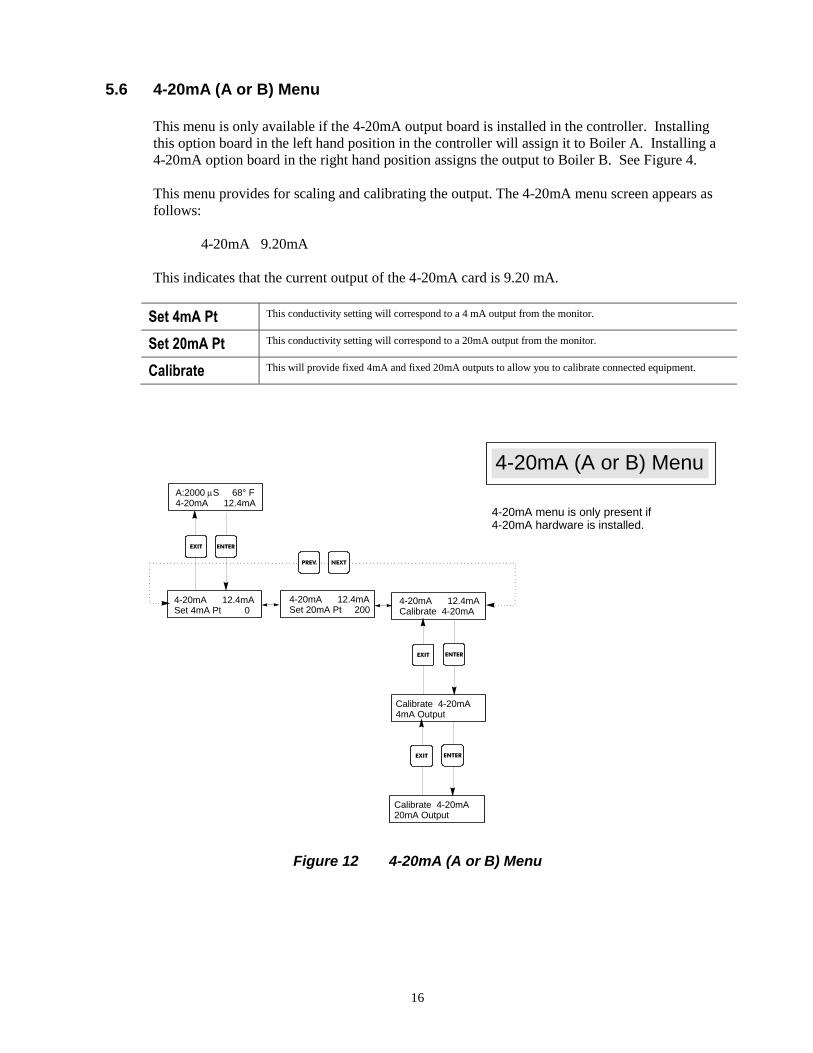
5.6 4-20mA (A or B) Menu
This menu is only available if the 4-20mA output board is installed in the controller. Installing
this option board in the left hand position in the controller will assign it to Boiler A. Installing a
4-20mA option board in the right hand position assigns the output to Boiler B. See Figure 4.
This menu provides for scaling and calibrating the output. The 4-20mA menu screen appears as
follows:
4-20mA 9.20mA
This indicates that the current output of the 4-20mA card is 9.20 mA.
Set 4mA Pt This conductivity setting will correspond to a 4 mA output from the monitor.
Set 20mA Pt This conductivity setting will correspond to a 20mA output from the monitor.
Calibrate This will provide fixed 4mA and fixed 20mA outputs to allow you to calibrate connected equipment.
Figure 12 4-20mA (A or B) Menu
A:2000 S 68° F4-20mA 12.4mA
4-20mA 12.4mASet 4mA Pt 0
4-20mA 12.4mASet 20mA Pt 200
4-20mA 12.4mACalibrate 4-20mA
Calibrate 4-20mA 4mA Output
Calibrate 4-20mA 20mA Output
4-20mA (A or B) Menu
ENTEREXIT
ENTEREXIT
ENTEREXIT
NEXTPREV.
4-20mA menu is only present if4-20mA hardware is installed.
17
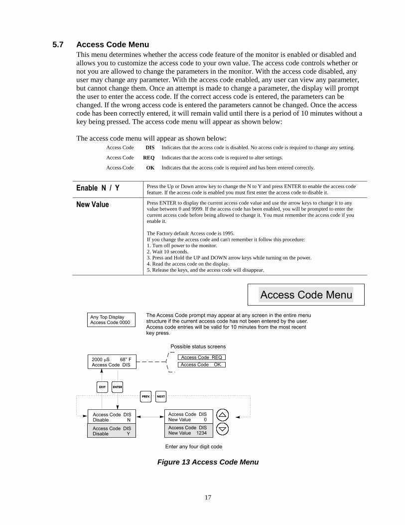
5.7 Access Code Menu
This menu determines whether the access code feature of the monitor is enabled or disabled and
allows you to customize the access code to your own value. The access code controls whether or
not you are allowed to change the parameters in the monitor. With the access code disabled, any
user may change any parameter. With the access code enabled, any user can view any parameter,
but cannot change them. Once an attempt is made to change a parameter, the display will prompt
the user to enter the access code. If the correct access code is entered, the parameters can be
changed. If the wrong access code is entered the parameters cannot be changed. Once the access
code has been correctly entered, it will remain valid until there is a period of 10 minutes without a
key being pressed. The access code menu will appear as shown below:
The access code menu will appear as shown below:
Access Code DIS Indicates that the access code is disabled. No access code is required to change any setting.
Access Code REQ Indicates that the access code is required to alter settings.
Access Code OK Indicates that the access code is required and has been entered correctly.
Enable N / Y Press the Up or Down arrow key to change the N to Y and press ENTER to enable the access code
feature. If the access code is enabled you must first enter the access code to disable it.
New Value Press ENTER to display the current access code value and use the arrow keys to change it to any value between 0 and 9999. If the access code has been enabled, you will be prompted to enter the
current access code before being allowed to change it. You must remember the access code if you
enable it.
The Factory default Access code is 1995.
If you change the access code and can't remember it follow this procedure: 1. Turn off power to the monitor.
2. Wait 10 seconds. 3. Press and Hold the UP and DOWN arrow keys while turning on the power.
4. Read the access code on the display.
5. Release the keys, and the access code will disappear.
Figure 13 Access Code Menu

18
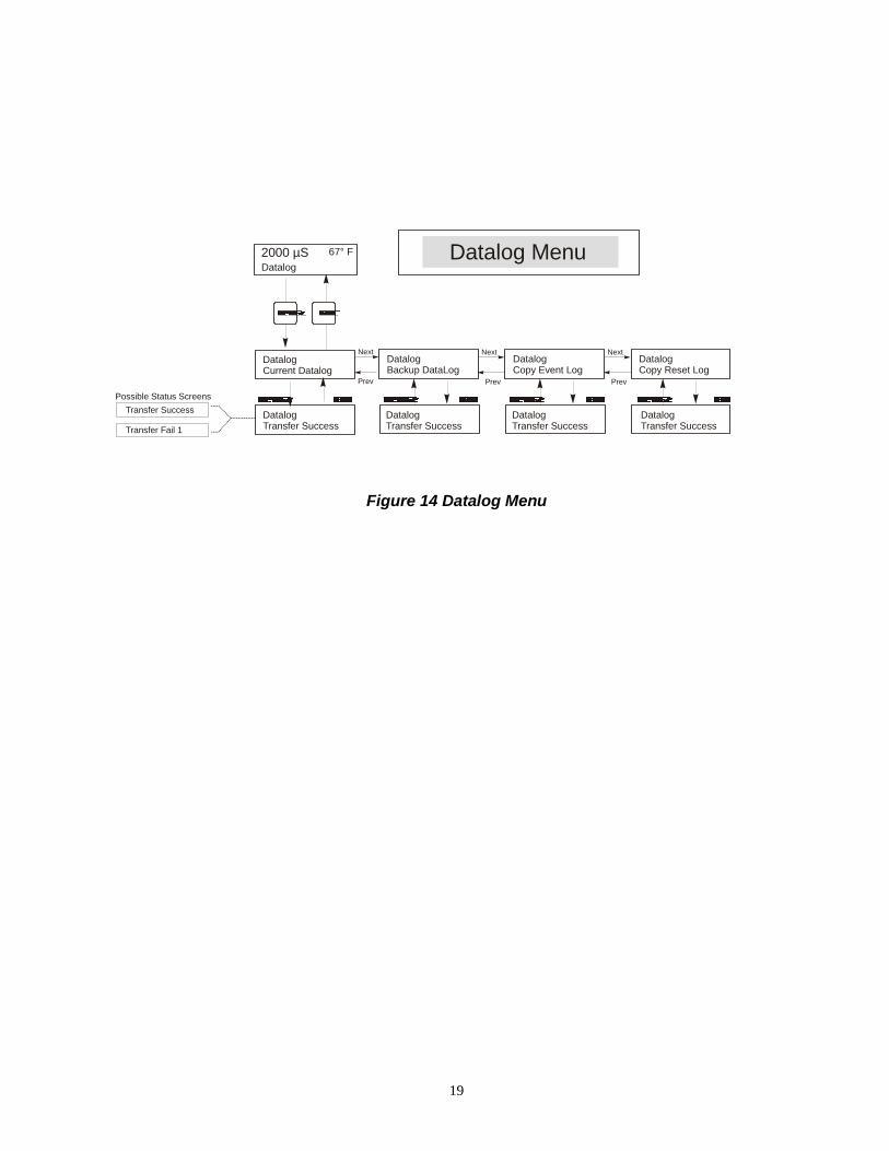
5.8 Datalog Menu
This menu is available if the data logging option has been purchased. This is indicated in the
model code by the letter U at the end of the model code. This menu allows you to save data from
the controller to a USB flash drive.
The controller has four logs, the Current Datalog, the Backup Datalog, the Event Log, and the
Reset Log. All files are in a CSV format that may be opened in a spreadsheet such as Microsoft
Excel.
Current Datalog Contains the following data taken at 10 minute intervals:
Conductivity Temperature
When the current datalog is downloaded to a USB stick, it is erased and a new log file is started.
If the current datalog is not downloaded before it reaches its maximum size (at least 60 days of
data) the oldest data is overwritten by the newest data.
Backup Datalog Contains the same data as the current log but it is never erased. When the backup log reaches its maximum size (at least 60 days of data), the oldest data is overwritten by the newest data.
Event Log Contains columns for each relay and flow switch input, as well as the date and time. Each time
any of these change state, the date and time is updated and it will show a 1 if the relay is on and 0 if it is off, and a 1 if the flow switch indicates no flow, 0 if there is flow. Tens of thousands of
events will be recorded before the oldest data is overwritten by the newest, the number varying
with the controller’s configuration.
Reset Log Consists of time stamps of when power was lost, when it was returned, and the cause of the reset.
Current or Backup Datalog
Place a USB flash drive with at least 10 MB capacity into the USB port on the front panel of the
controller. Press the Enter key to download the file from the controller to the disk. The file name for the Current Datalog will be Datalog<serial number><date><time>.csv using the date and time
it was downloaded. The file name for the Backup Datalog will be Datalog<serial
number><date><time> .csv using the date and time it was created.
The controller will display the progress of the file download process. If the file was successfully
copied to the USB disk the controller will display Transfer Success.
Copy Event Log Place a USB flash drive with at least 10 MB capacity into the USB port on the front panel of the
controller. Press the Enter key to download the file from the controller to the stick. The file name will be Eventlog<serial number><date><time>.csv.
The controller will display the progress of the file download process. If the file was successfully
copied to the USB disk the controller will display Transfer Success, otherwise Transfer Fail 1.
Transfer Success Transfer Fail 1
Copy Reset Log
Place a USB flash drive with at least 10 MB capacity into the USB port on the front panel of the
controller. Press the Enter key to download the file from the controller to the stick. The file name will be Resetlog<serial number><date><time>.csv.
The controller will display the progress of the file download process. If the file was successfully
copied to the USB disk the controller will display Transfer Success.
Transfer Success Transfer Fail 1
19
DatalogCurrent Datalog
DatalogCopy Event Log
Datalog Menu 67° F
Datalog
2000 µS
DatalogTransfer Success
Next
Prev
DatalogCopy Reset Log
Next
Prev
DatalogTransfer Success
DatalogTransfer Success
Possible Status Screens
Transfer Success
Transfer Fail 1
DatalogBackup DataLog
Next
Prev
DatalogTransfer Success
Figure 14 Datalog Menu
20
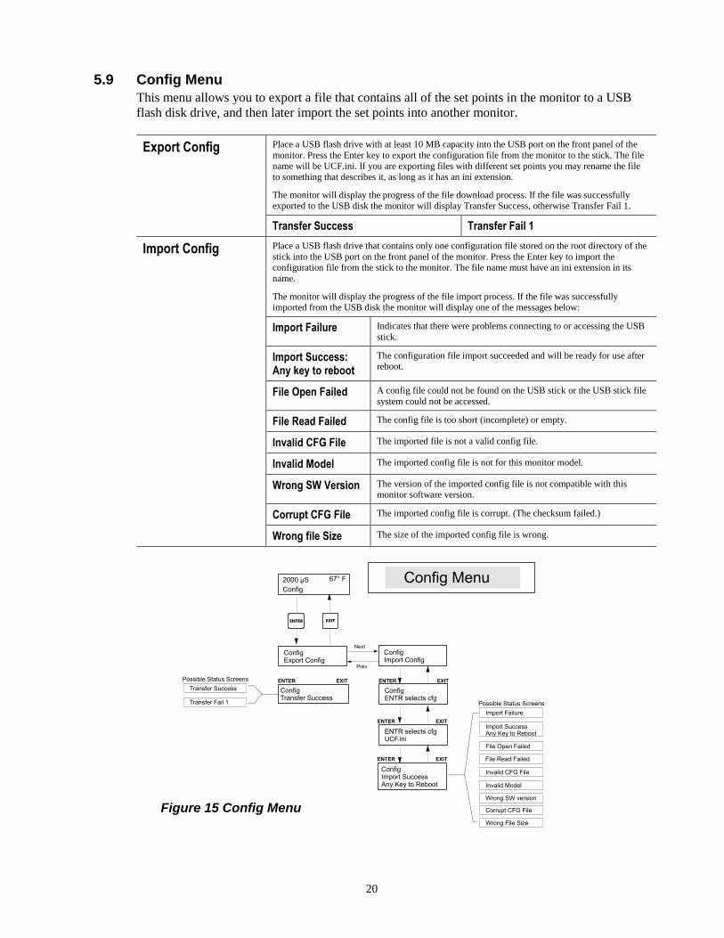
5.9 Config Menu
This menu allows you to export a file that contains all of the set points in the monitor to a USB
flash disk drive, and then later import the set points into another monitor.
Export Config Place a USB flash drive with at least 10 MB capacity into the USB port on the front panel of the
monitor. Press the Enter key to export the configuration file from the monitor to the stick. The file name will be UCF.ini. If you are exporting files with different set points you may rename the file
to something that describes it, as long as it has an ini extension.
The monitor will display the progress of the file download process. If the file was successfully exported to the USB disk the monitor will display Transfer Success, otherwise Transfer Fail 1.
Transfer Success Transfer Fail 1
Import Config Place a USB flash drive that contains only one configuration file stored on the root directory of the
stick into the USB port on the front panel of the monitor. Press the Enter key to import the configuration file from the stick to the monitor. The file name must have an ini extension in its
name.
The monitor will display the progress of the file import process. If the file was successfully imported from the USB disk the monitor will display one of the messages below:
Import Failure Indicates that there were problems connecting to or accessing the USB
stick.
Import Success: Any key to reboot
The configuration file import succeeded and will be ready for use after reboot.
File Open Failed A config file could not be found on the USB stick or the USB stick file
system could not be accessed.
File Read Failed The config file is too short (incomplete) or empty.
Invalid CFG File The imported file is not a valid config file.
Invalid Model The imported config file is not for this monitor model.
Wrong SW Version The version of the imported config file is not compatible with this monitor software version.
Corrupt CFG File The imported config file is corrupt. (The checksum failed.)
Wrong file Size The size of the imported config file is wrong.
Figure 15 Config Menu
21
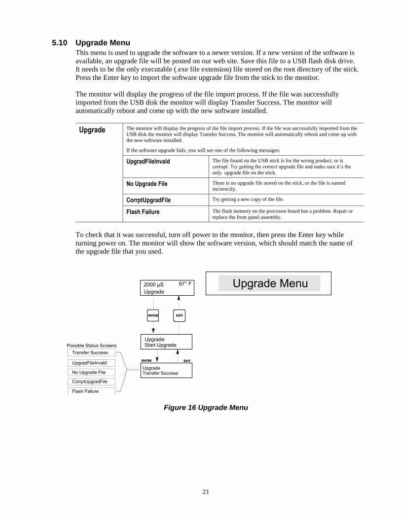
5.10 Upgrade Menu
This menu is used to upgrade the software to a newer version. If a new version of the software is
available, an upgrade file will be posted on our web site. Save this file to a USB flash disk drive.
It needs to be the only executable (.exe file extension) file stored on the root directory of the stick.
Press the Enter key to import the software upgrade file from the stick to the monitor.
The monitor will display the progress of the file import process. If the file was successfully
imported from the USB disk the monitor will display Transfer Success. The monitor will
automatically reboot and come up with the new software installed.
Upgrade The monitor will display the progress of the file import process. If the file was successfully imported from the USB disk the monitor will display Transfer Success. The monitor will automatically reboot and come up with
the new software installed.
If the software upgrade fails, you will see one of the following messages:
UpgradFileInvald The file found on the USB stick is for the wrong product, or is
corrupt. Try getting the correct upgrade file and make sure it’s the
only upgrade file on the stick.
No Upgrade File There is no upgrade file stored on the stick, or the file is named incorrectly.
CorrptUpgradFile Try getting a new copy of the file.
Flash Failure The flash memory on the processor board has a problem. Repair or
replace the front panel assembly.
To check that it was successful, turn off power to the monitor, then press the Enter key while
turning power on. The monitor will show the software version, which should match the name of
the upgrade file that you used.
Figure 16 Upgrade Menu
22
6.0 MAINTENANCE
The WDC monitor itself requires very little maintenance. Wipe with a damp cloth. Do not spray
down the monitor unless the enclosure door is closed and latched.
6.1 Electrode Cleaning
NOTE: The monitor must be recalibrated after cleaning the electrodes.
Frequency The electrodes should be cleaned periodically. The frequency required will vary by installation. In
a new installation, it is recommended that the electrodes be cleaned after two weeks of service. To
determine how often the electrodes must be cleaned, follow the procedure below.
1. Read and record the conductivity.
2. Remove, clean and replace the conductivity electrodes in the process.
3. Read conductivity and compare with the reading in step 1 above.
If the variance in readings is greater than 5%, increase the frequency of electrode cleaning. If
there is less than 5% change in the reading, the electrodes were not dirty and can be cleaned less
often.
Cleaning Procedure The electrodes can normally be cleaned using a cloth or paper towel and a mild cleaning solution
such as 409® cleanser. Occasionally an electrode may become coated with various substances
which require a more vigorous cleaning procedure, such as immersion in dilute muriatic acid.
Usually the coating will be visible, but not always.
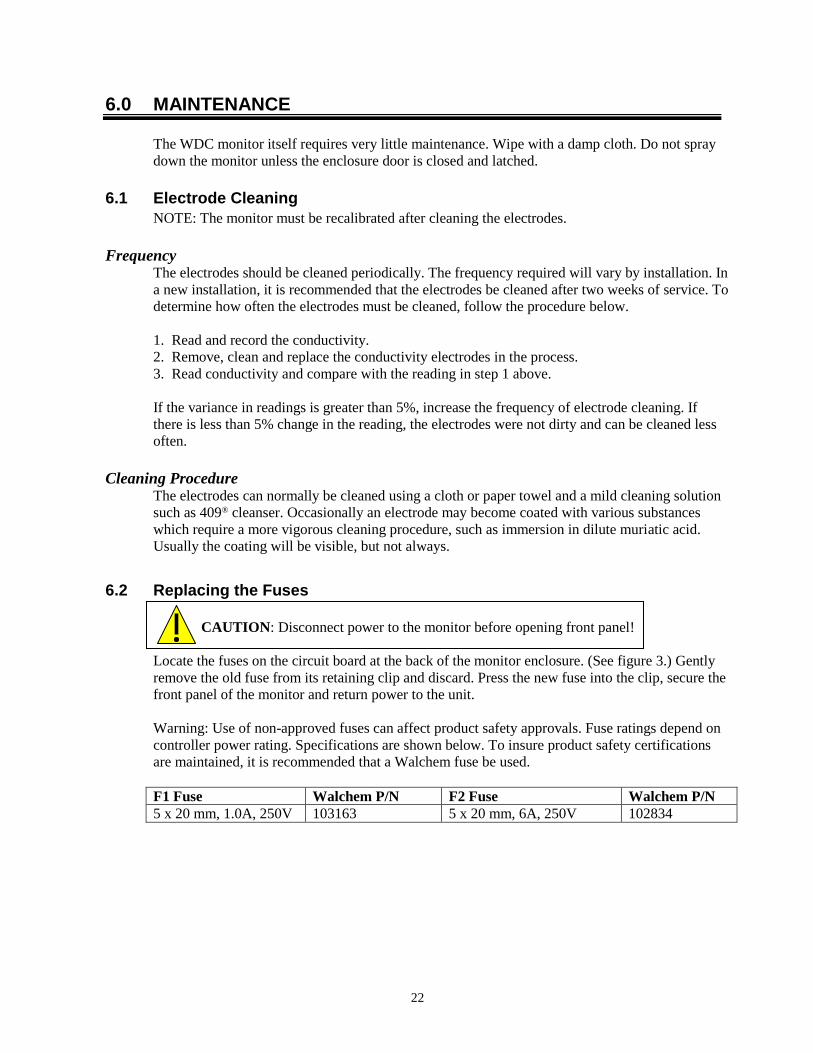
6.2 Replacing the Fuses
CAUTION: Disconnect power to the monitor before opening front panel!
Locate the fuses on the circuit board at the back of the monitor enclosure. (See figure 3.) Gently
remove the old fuse from its retaining clip and discard. Press the new fuse into the clip, secure the
front panel of the monitor and return power to the unit.
Warning: Use of non-approved fuses can affect product safety approvals. Fuse ratings depend on
controller power rating. Specifications are shown below. To insure product safety certifications
are maintained, it is recommended that a Walchem fuse be used.
F1 Fuse Walchem P/N F2 Fuse Walchem P/N
5 x 20 mm, 1.0A, 250V 103163 5 x 20 mm, 6A, 250V 102834

23
7.0 TROUBLESHOOTING
CAUTION: Disconnect power to the monitor before opening front panel!
Troubleshooting and repair of a malfunctioning monitor should only be attempted by qualified
personnel using caution to ensure safety and limit unnecessary further damage. Contact the
factory.
7.1 Error Messages
TEMP ERROR
This error condition indicates that the temperature signal from the conductivity electrode is no longer valid. The controller will revert to manual temperature compensation.
Possible Cause Corrective Action
Green or White electrode wire disconnected. Reconnect.
Faulty electrode Replace electrode.
Revert to manual temperature compensation by cycling power off
and on.
COND ERROR This error condition will stop conductivity control. It indicates that the conductivity signal from the electrode is no longer valid.
This prevents controlling based upon a bogus conductivity reading.
Possible Cause Corrective Action
Black or red electrode wire shorted Disconnect short.
Faulty electrode Replace electrode.
Faulty controller Verify via failed self test.
COND HIGH ALARM This error message indicates that the conductivity is above the programmed percentage above set point. The conductivity will continue to be monitored, and the divert and feed outputs will be allowed to be activated.
Possible Cause Corrective Action
Fouled conductivity electrode See Conductivity Electrode Troubleshooting section.
Divert flow rate too low Check for clogged strainer. Check for insufficient pressure differential.
Divert valve not opening Check for faulty divert valve. Check divert valve wiring. Check
controller relay.
Conductivity rose over alarm limit while biocide lockout occurred
Allow normal divert to occur.
COND LOW ALARM This error message indicates that the conductivity is below the programmed percentage below set point. The conductivity will
continue to be monitored, and the feed output will be allowed to be activated.
Possible Cause Corrective Action
Fouled conductivity electrode See Conductivity Electrode Troubleshooting section.
Electrode disconnected Reconnect.
Electrode dry See “No Flow “Troubleshooting section
Divert valve stuck open Check for faulty divert valve. Check divert valve wiring. Check controller relay.
Biocide prebleed set too low Change prebleed set point to be above low alarm if desired.
24
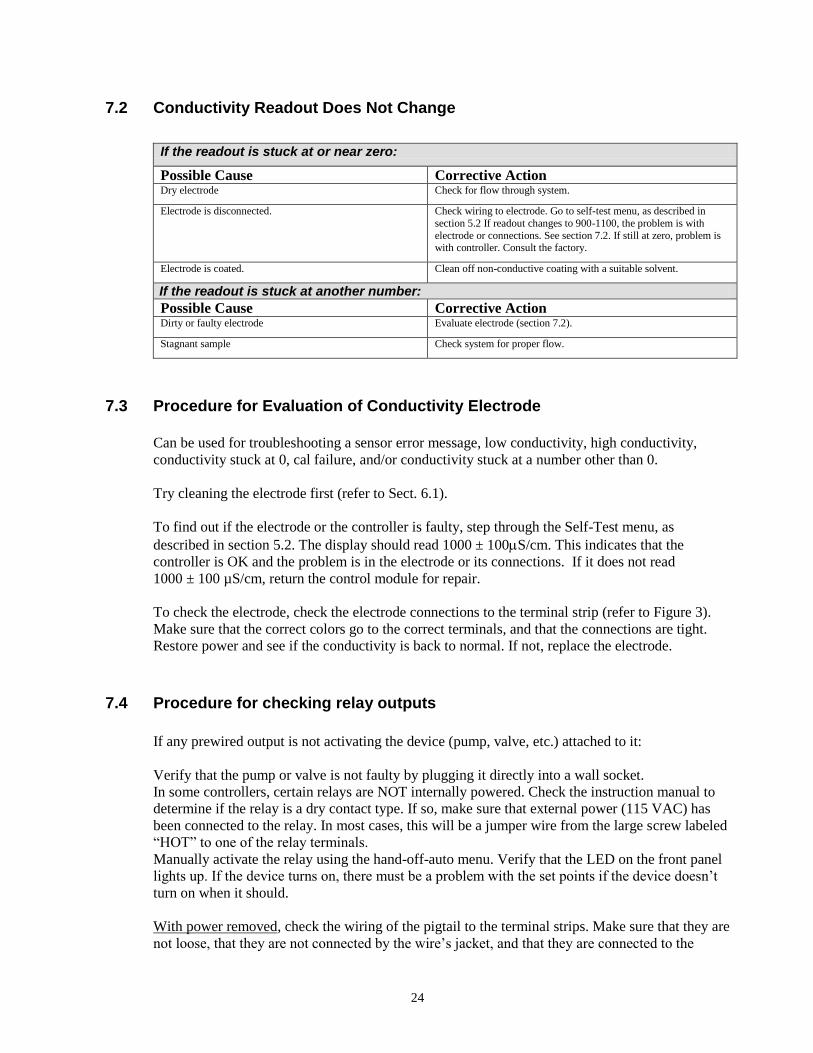
7.2 Conductivity Readout Does Not Change
If the readout is stuck at or near zero:
Possible Cause Corrective Action Dry electrode Check for flow through system.
Electrode is disconnected. Check wiring to electrode. Go to self-test menu, as described in
section 5.2 If readout changes to 900-1100, the problem is with
electrode or connections. See section 7.2. If still at zero, problem is with controller. Consult the factory.
Electrode is coated. Clean off non-conductive coating with a suitable solvent.
If the readout is stuck at another number:
Possible Cause Corrective Action Dirty or faulty electrode Evaluate electrode (section 7.2).
Stagnant sample Check system for proper flow.
7.3 Procedure for Evaluation of Conductivity Electrode
Can be used for troubleshooting a sensor error message, low conductivity, high conductivity,
conductivity stuck at 0, cal failure, and/or conductivity stuck at a number other than 0.
Try cleaning the electrode first (refer to Sect. 6.1).
To find out if the electrode or the controller is faulty, step through the Self-Test menu, as
described in section 5.2. The display should read 1000 ± 100S/cm. This indicates that the
controller is OK and the problem is in the electrode or its connections. If it does not read
1000 ± 100 µS/cm, return the control module for repair.
To check the electrode, check the electrode connections to the terminal strip (refer to Figure 3).
Make sure that the correct colors go to the correct terminals, and that the connections are tight.
Restore power and see if the conductivity is back to normal. If not, replace the electrode.
7.4 Procedure for checking relay outputs
If any prewired output is not activating the device (pump, valve, etc.) attached to it:
Verify that the pump or valve is not faulty by plugging it directly into a wall socket.
In some controllers, certain relays are NOT internally powered. Check the instruction manual to
determine if the relay is a dry contact type. If so, make sure that external power (115 VAC) has
been connected to the relay. In most cases, this will be a jumper wire from the large screw labeled
“HOT” to one of the relay terminals.
Manually activate the relay using the hand-off-auto menu. Verify that the LED on the front panel
lights up. If the device turns on, there must be a problem with the set points if the device doesn’t
turn on when it should.
With power removed, check the wiring of the pigtail to the terminal strips. Make sure that they are
not loose, that they are not connected by the wire’s jacket, and that they are connected to the

25
correct terminal. Also check the removable terminal block where the black (hot) wires attach
(TB2) to see if it has pulled loose. Restore power and manually activate the relay.
With power removed, remove the terminal block that has the black (hot) wires from all of the
pigtails (TB2). This simply pulls up off some metal pins. Check these pins for corrosion. If they
seem coated with anything, scrape off the coating by replacing and removing the terminal block
several times. Restore power and manually activate the relay.
With power removed, remove the TB2 terminal block again, and attach one lead of a multimeter
to the pin that lines up with the wire for the relay in question, and the other lead on the other side
of the relay (this will be an adjacent pin for a dry contact relay, or neutral at TB3 for a powered
relay). Set the meter to read resistance. Restore power and verify that the meter reads infinite
ohms with the relay off (open) and very low ohms with the relay on (closed). If it always reads
infinite ohms, the controller is faulty.
8.0 SERVICE POLICY
The WDC series Condensate Monitor has a 2-year warranty on electronic components and a 1-
year warranty on mechanical parts (keypad, terminal strip and relays).
We stock circuit boards for immediate exchange after we have isolated the cause of the problem.
Factory authorized repairs that are received by next-day-air will be returned within 24 hours.
Normal priority for returns is two weeks.
Out of warranty repairs or circuit board exchanges are done on a flat fee basis after the warranty is
expired.

FIVE BOYNTON ROAD HOPPING BROOK PARK HOLLISTON, MA 01746 USA TEL: 508-429-1110 FAX: 508-429-7433 Web: www.walchem.com