WCCTech RF Test Planfiles.ctia.org/pdf/cwg_rf_test_plan_1.3.pdf · 2009-06-18 · Nokia Mobile...
63
Test Plan for RF Performance Evaluation of Wi-Fi Mobile Converged Devices Version 1.3 June 2009 © 2006 CTIA – The Wireless Association (CTIA) and Wi-Fi Alliance (WFA). All rights reserved. CTIA and WFA have granted a license to Authorized Testing Laboratories to use this Test Plan for the sole purpose of testing wireless products for their respective Certification Programs. Any reproduction or transmission of all or part of this Test Plan, in any form or by any means, electronic or mechanical, including photocopying, recording, or any information CTIA and WFA is unauthorized and strictly prohibited. Test laboratories that are not Authorized Testing Laboratories that wish to use this test Plan must receive written permission from CTIA and WFA prior to such use.
Transcript of WCCTech RF Test Planfiles.ctia.org/pdf/cwg_rf_test_plan_1.3.pdf · 2009-06-18 · Nokia Mobile...

Test Plan for RF Performance Evaluation of
Wi-Fi Mobile Converged Devices
Version 1.3 June 2009
© 2006 CTIA – The Wireless Association (CTIA) and Wi-Fi Alliance (WFA). All rights reserved. CTIA and WFA have granted a license to Authorized Testing Laboratories to use this Test Plan for the sole purpose of testing wireless products for their respective Certification Programs. Any reproduction or transmission of all or part of this Test Plan, in any form or
by any means, electronic or mechanical, including photocopying, recording, or any information CTIA and WFA is unauthorized and strictly prohibited. Test laboratories that are not Authorized Testing Laboratories that wish to use this
test Plan must receive written permission from CTIA and WFA prior to such use.

Certification Program Test Plan
June 2009 Page 2 of 63 Version 1.3
Interested parties may obtain permission to reproduce a limited number of copies by contacting CTIA or Wi-Fi Alliance at:
CTIA - The Wireless Association
1400 16th Street, NW Suite 600
Washington, DC 20036 Phone: 1.202.785.0081
Fax: 1.202.466.3413 Email: [email protected]
Wi-Fi Alliance 3925 West Braker Lane
Austin, TX 78729 Phone: 1.512.305.0790
Fax: 1.512.305.0791 Email: [email protected]
Acknowledgments: This test plan was created by the wireless industry with input from the following
companies and their representatives:
Company Representative Azimuth Systems Charles Wright CETECOM, Inc Lothar Schmidt
Cingular Jason Brown DSP Group Graham Smith
ETS-Lindgren Dr. Michael Foegelle Ixia Larry Green
Nokia Mobile Phones, Inc. Alan Ewing Steve Wilhoff
Philips Semiconductor Steve Shearer Sprint Alex Tkatch
Telecommunications Metrology Center of China Ministry of Information Industry Gao Hong
Wi-Fi Alliance Patrick Green

Certification Program Test Plan
June 2009 Page 3 of 63 Version 1.3
Change History
Version Date Comments 1.0 08-Aug-2006 Document Approved 1.1 20-Aug-2007 • Updated Purpose and References sections
• Clarified text and added footnote in Radiated RF Tests nomenclature section
• Clarified text in Minimum Measurement Distance section • Clarified testing conditions for cellular inactive state • Corrected step reference in step 14 of Receive Sensitivity
Measurement. Removed repeated text. • Removed reference to CTIA website for traffic generator software
download • Corrected step 1 and clarified language in step 9 regarding
antenna connection in WLAN Access Point Testing Methodology section
• Removed requirement for OFMD transmit mask test on Mobile Stations and Access Points
• Updated WLAN Test Set Estimated Signal Level tables • Added Sample Summation test report table • Corrected title on Test 5.2.2. and 6.2.2 test report table • Aded text to clarify that Wi-Fi desense testing is done in free-
space only • Carified that cellular desense testing is done in free-space only,
and to perform reference measurements if not previously done • Removed references to specific test equipment from document
1.2 26-June-2008 • 5 GHz TRP, TIS, & Reference Measurement frequency changes – Sections 5.1.1.2, 5.1.2.2, 5.2.1.2, 5.2.2.2, Table 5.2 5, 6.1.1.2, 6.1.2.2, 6.2.1.2, 6.2.2.2, Table B2 , Table B3, Table B4, Table B5, Table B6, Table B7, New Appendix D
• Other sections changed: Table B1 - CID Added, section 1.4 - CTIA Reference updated, Table A1 Channel change UTRA FDD Band I - IV, 4120/824.0 changed to 4132/826.4, Table B3 Reference changed from (2) to (1), Table 5.1.1 and table 6.1.1 - removed "Check TX Mask" from comments column
1.3 16 June, 2009 • Added footnote to Section 1.2, 3rd sentence • Added text to Section 4.1, 2nd sentence • Added CTIA Request # to Appendix B table • Added Appendix E Device Capabilities Testing Matrix

Certification Program Test Plan
June 2009 Page 4 of 63 Version 1.3
Table of Contents 1. Introduction .................................................................................................................................. 9
1.1 Background ........................................................................................................................... 9 1.2 Scope .................................................................................................................................... 9 1.3 Purpose ................................................................................................................................. 9 1.4 References ............................................................................................................................ 9 1.5 Test Nomenclature Overview ............................................................................................... 10
1.5.1 Radiated RF Tests ........................................................................................................ 10 1.5.2 Conducted RF Tests ..................................................................................................... 10
1.6 Characterization of Measurements ...................................................................................... 10 1.6.1 Measurement Techniques ............................................................................................ 10 1.6.2 Measurement Uncertainty ............................................................................................. 10 1.6.3 Minimum Measurement Distance.................................................................................. 11 1.6.4 Equipment Required ..................................................................................................... 11 1.6.5 Quiet Zone Test Frequencies ....................................................................................... 11
2. WLAN Client Testing Methodology ............................................................................................. 12 2.1 WLAN Test Set .................................................................................................................... 13 2.2 Conducted RF Tests ............................................................................................................ 14
2.2.1 Test Set-up ................................................................................................................... 14 2.2.2 Transmit Power Measurement ...................................................................................... 14 2.2.2.1 Discussion ................................................................................................................ 14 2.2.2.2 Unicast Test Packets ................................................................................................ 14 2.2.2.3 Test Procedure ......................................................................................................... 15 2.2.2.4 Results ...................................................................................................................... 15 2.2.3 Receive Sensitivity Measurement ................................................................................. 15 2.2.3.1 Discussion ................................................................................................................ 15 2.2.3.2 Unicast Test Packets ................................................................................................ 16 2.2.3.3 Test Procedure ......................................................................................................... 16 2.2.3.4 Results ...................................................................................................................... 16
2.3 Radiated RF Tests ............................................................................................................... 17 2.3.1 Test Set-up ................................................................................................................... 17 2.3.2 Radiated Power ............................................................................................................ 17 2.3.2.1 Discussion ................................................................................................................ 17 2.3.2.2 Unicast Test Packets ................................................................................................ 17 2.3.2.3 Test Procedure ......................................................................................................... 17 2.3.2.4 Results ...................................................................................................................... 18 2.3.3 Receive Sensitivity Measurement ................................................................................. 18 2.3.3.1 Discussion ................................................................................................................ 18 2.3.3.2 Unicast Test Packets ................................................................................................ 19 2.3.3.3 Procedure ................................................................................................................. 19 2.3.3.4 Results ...................................................................................................................... 19 2.3.4 Radiated Receiver Sensitivity Degradation, Simultaneous Operation (Wi-Fi Desense) . 19 2.3.4.1 Equipment ................................................................................................................. 19 2.3.4.2 Unicast Test Packets ................................................................................................ 20 2.3.4.3 Procedure ................................................................................................................. 20 2.3.5 Radiated Cellular Receiver Sensitivity Degradation, Simultaneous Operation (Cellular Desense) ................................................................................................................................... 20 2.3.5.1 Equipment ................................................................................................................. 20

Certification Program Test Plan
June 2009 Page 5 of 63 Version 1.3
2.3.5.2 Wi-Fi DUT Transmitter Stimulus ................................................................................ 21 2.3.5.3 Procedure ................................................................................................................. 22
3. WLAN Access Point Testing Methodology ................................................................................. 23 3.1 Conducted RF Tests ............................................................................................................ 23
3.1.1 Test Set-up ................................................................................................................... 23 3.1.2 Equipment .................................................................................................................... 23 3.1.3 Transmit Power Measurement ...................................................................................... 23 3.1.3.1 Unicast Test Packets ................................................................................................ 23 3.1.3.2 Test Procedure ......................................................................................................... 23 3.1.3.3 Results ...................................................................................................................... 24 3.1.4 Receive Sensitivity Measurement ................................................................................. 24 3.1.4.1 Unicast Test Packets ................................................................................................ 24 3.1.4.2 Test Procedure ......................................................................................................... 24 3.1.4.3 Results ...................................................................................................................... 25
3.2 Radiated RF Tests ............................................................................................................... 25 3.2.1 Test Set-up ................................................................................................................... 25 3.2.2 Equipment .................................................................................................................... 26 3.2.3 Radiated Power ............................................................................................................ 26 3.2.3.1 Discussion ................................................................................................................ 26 3.2.3.2 Unicast Test Packets ................................................................................................ 26 3.2.3.3 Test Procedure ......................................................................................................... 26 3.2.3.4 Results ...................................................................................................................... 27 3.2.4 Receive Sensitivity Measurement ................................................................................. 27 3.2.4.1 Discussion ................................................................................................................ 27 3.2.4.2 Unicast Test Packets ................................................................................................ 27 3.2.4.3 Test Procedure ......................................................................................................... 27 3.2.4.4 Results ...................................................................................................................... 28
4. Radiated Measurements ............................................................................................................ 29 4.1 Test Conditions for Device Under Test ................................................................................ 29
5. Mobile Station Testing ................................................................................................................ 30 5.1 Transmitter Performance ..................................................................................................... 30
5.1.1 Conducted Power Output ............................................................................................. 30 5.1.1.1 DUT Requirements ................................................................................................... 30 5.1.1.2 Frequency Channels ................................................................................................. 30 5.1.1.3 Data Rates ................................................................................................................ 30 5.1.1.4 Not Used ................................................................................................................... 30 5.1.1.5 Results ...................................................................................................................... 30 5.1.2 Total Radiated Power (TRP) ......................................................................................... 30 5.1.2.1 DUT Requirements ................................................................................................... 30 5.1.2.2 Frequency Channels ................................................................................................. 30 5.1.2.3 Data Rates ................................................................................................................ 31 5.1.2.4 Results ...................................................................................................................... 31
5.2 Receiver Performance ......................................................................................................... 31 5.2.1 Conducted Receiver Sensitivity .................................................................................... 31 5.2.1.1 DUT Requirements ................................................................................................... 31 5.2.1.2 Frequency Channels ................................................................................................. 32 5.2.1.3 Data Rates ................................................................................................................ 32 5.2.1.4 Results ...................................................................................................................... 32 5.2.2 Total Isotropic Sensitivity (TIS) ..................................................................................... 32 5.2.2.1 DUT Requirements ................................................................................................... 32

Certification Program Test Plan
June 2009 Page 6 of 63 Version 1.3
5.2.2.2 Frequency Channels ................................................................................................. 32 5.2.2.3 Data Rates ................................................................................................................ 32 5.2.2.4 Results ...................................................................................................................... 33 5.2.3 Radiated Receiver Sensitivity, Simultaneous Operation (Wi-Fi Desense) ..................... 33 5.2.3.1 DUT Requirements ................................................................................................... 33 5.2.3.2 Positions ................................................................................................................... 33 5.2.3.3 Highest Cellular Frequency Channel Test ................................................................. 33 5.2.3.4 Harmonic Interference Tests ..................................................................................... 33 5.2.3.5 Results ...................................................................................................................... 34 5.2.4 Radiated Cellular Receiver Sensitivity, Simultaneous Operation (Cellular Desense) .... 34 5.2.4.1 DUT Requirements ................................................................................................... 34 5.2.4.2 DUT Polarization ....................................................................................................... 34 5.2.4.3 Wi-Fi Frequency ........................................................................................................ 35 5.2.4.4 Cellular Technology and Frequency Band ................................................................. 35 5.2.4.5 Results ...................................................................................................................... 36
6. Access Point Testing .................................................................................................................. 37 6.1 Transmitter Performance ..................................................................................................... 37
6.1.1 Conducted Power Output ............................................................................................. 37 6.1.1.1 APUT Requirements ................................................................................................. 37 6.1.1.2 Frequency Channels ................................................................................................. 37 6.1.1.3 Data Rates ................................................................................................................ 37 6.1.1.4 Not Used ................................................................................................................... 37 6.1.1.5 Results ...................................................................................................................... 37 6.1.2 Total Radiated Power (TRP) ......................................................................................... 37 6.1.2.1 APUT Requirements ................................................................................................. 37 6.1.2.2 Frequency Channels ................................................................................................. 37 6.1.2.3 Data Rates ................................................................................................................ 38 6.1.2.4 Results ...................................................................................................................... 38
6.2 Receiver Performance ......................................................................................................... 38 6.2.1 Conducted Receive Sensitivity ..................................................................................... 38 6.2.1.1 APUT Requirements ................................................................................................. 38 6.2.1.2 Frequency Channels ................................................................................................. 38 6.2.1.3 Data Rates ................................................................................................................ 39 6.2.1.4 Results ...................................................................................................................... 39 6.2.2 Total Isotropic Sensitivity (TIS) ..................................................................................... 39 6.2.2.1 APUT Requirements ................................................................................................. 39 6.2.2.2 Frequency Channels ................................................................................................. 39 6.2.2.3 Data Rates ................................................................................................................ 39 6.2.2.4 Results ...................................................................................................................... 40
7. WLAN Test Set .......................................................................................................................... 41 7.1 Estimated Signal Levels....................................................................................................... 41 7.2 Test AP and WLAN Station Requirements ........................................................................... 44
7.2.1 Basic Parameters ......................................................................................................... 44 7.2.2 RF Parameters ............................................................................................................. 44
7.3 WLAN Receiver RF Requirements ...................................................................................... 45 7.4 Attenuator Requirements ..................................................................................................... 46
8. Appendix A – Harmonic Interference Selection Matricies ........................................................... 48 9. Appendix B – Summary Test Report .......................................................................................... 50 10. Appendix C – RF Power Measurement ................................................................................ 61 11. APPENDIX D – IEEE 802.11a Supported Channel Option Examples .................................. 62

Certification Program Test Plan
June 2009 Page 7 of 63 Version 1.3
12. Appendix E – Device Testing Configurations ....................................................................... 63 List of Figures Figure 2.1 – Block Schematic Diagram – WLAN Test Set .................................................................... 13Figure 2.2 – Block Schematic Diagram – Conducted RF Tests ............................................................ 14Figure 2.3 – Block Schematic Diagram – Radiated RF Tests ............................................................... 17Figure 2.4 – Test Configuration – Cellular Desense due to Wi-Fi ......................................................... 21Figure 3.1 – Block Schematic Diagram – Conducted RF Test for AP ................................................... 23Figure 3.2 – Block Schematic Diagram – Radiated RF Tests for AP .................................................... 25
List of Tables Table 1.1 - Minimum Measurement Distance ....................................................................................... 11Table 5.1 – Wi-Fi Channel and Data Rate for TIS Wi-Fi Desense ........................................................ 33Table 5.2 – Channel setting for Wi-Fi U-NII Band for TIS Cellular Desense ......................................... 35Table 7.1 – Conducted TX Test ........................................................................................................... 41Table 7.2 – Conducted RX Test ........................................................................................................... 42Table 7.3 – Radiated TX Test .............................................................................................................. 43Table A.1 – IEEE 802.11b/g Productsa ................................................................................................ 48Table A.2 – IEEE 802.11a Products ..................................................................................................... 49Table B.1 – Sample Summation .......................................................................................................... 50Table B.2 – Conducted Power Output Results ..................................................................................... 50Table B.3 – Mode Radiated Figure of Merit Results ............................................................................. 51Table B.4 – Radiated Reference Measurements Results ..................................................................... 51Table B.5 – Conducted Receiver Sensitivity Results ............................................................................ 53Table B.6 – Mode Sensitivity Figure of Merit Results ........................................................................... 54Table B.7 – Sensitivity Reference Measurements Results ................................................................... 55Table B.8 – Highest Cellular Frequency Channel Test Results ............................................................ 57Table B.9 – Harmonic Interference Tests Results 802.11b&g .............................................................. 58Table B.10 – Harmonic Interference Tests Results 802.11a ................................................................ 58Table B.11 – Cellular Desense Test Results for 802.11b&g Operation ................................................ 59Table B.12 – Cellular Desense Test Results for 802.11a Operation ..................................................... 60

Certification Program Test Plan
June 2009 Page 8 of 63 Version 1.3
List of Acronyms and Definitions ACK Acknowledge AMPS Advanced Mobile Phone System APSD Automatic Power Save Delivery APUT Access Point Under Test BPSK Binary Phase Shift Keying CCK Complementary Code Keying CDMA Code Division Multiple Access DBPSK Differential Binary Phase Shift Keying DQPSK Differential Quadrature Phase Shift Keying DSSS Direct Sequence Spread Spectrum DUT Device Under Test EUT Equipment Under Test FRR Frame Reception Rate GSM Global System for Mobile communication iDEN Integrated Digital Enhanced Network LAN Local Area Network LCR Low Chip Rate OFDM Orthogonal Frequency Division Multiplexing PER Packet Error Rate PHS Personal Handyphone System (Japan) QAM Quadrature Amplitude Modulation QPSK Quadrature Phase Shift Keying RSSI Receive Signal Strength Indicator Rx Receive Signal Strength Indicator SSID Service Set Identifier STA Station TIS Total Isotropic Sensitivity TRP Total Radiated Power Tx Transmit UMTS Universal Mobile Telecommunications System UTRA-FDD UMTS Terrestrial Radio Access - Frequency Division Duplexing UTRA-TDD UMTS Terrestrial Radio Access - Time Division Duplexing WLAN Wireless Local Area Network

Certification Program Test Plan
June 2009 Page 9 of 63 Version 1.3
1. INTRODUCTION 1.1
Increasingly the wireless market is seeing converged handset devices that incorporate both cellular and wireless local area network (WLAN or Wi-Fi) functionality. Cellular operators are becoming one of the largest classes of Wi-Fi service providers
Background
1
1.2
and are increasingly working to integrate more WLAN support into their overall operations. Due to the many potential applications and deployment scenarios that converged equipment may ultimately function in, operators and handset vendors are interested in a uniform method of profiling the RF performance of converged devices. With this profile data gathered in a uniform way, equipment designers, system operators, and RF engineers have the flexibility to determine their own appropriate RF performance criteria based on their engineering assessments, and they can easily identify equipment that is suitable for each deployment and application.
This Test Document contains the proposed test methodologies and performance criteria for the RF performance evaluation of Wi-Fi mobile converged devices. The scope of testing includes devices that support IEEE 802.11a, IEEE 802.11b or 802.11g, as well as one or more cellular technologies. Support for IEEE standards must be confirmed through Wi-Fi Alliance baseline certification—that is, devices tested using this testplan must first be Wi-Fi CERTIFIED for IEEE 802.11a, 802.11b, or 802.11g
Scope
2
1.3
. Cellular technologies include, but are not limited to, GSM, CDMA, UMTS, operating at conventional 450, 800, 900, 1800, 1900 and 2100 MHz frequencies.
The purpose of this document is first to define the test methodology for the RF Testing of Wi-Fi mobile converged devices and then to specify the test conditions for each proposed test. The testing covers client devices and access points, and specifies conducted as well as radiated tests.
Purpose
The test methodology requires the device be placed in a standard operational mode. Although recognizing that the use of special test modes would enable more simplified testing and the use of formal test equipment, the test methodology proposed in this document allows the testing of any Wi-Fi mobile device in a mode that is as close as possible to its native operation.
This test plan is part of the CTIA and Wi-Fi Alliance certification programs. The CTIA Certification Program is explained in a separate document titled CTIA Certification Program Management Document [4]. The Wi-Fi Alliance Certification Program is explained in a separate document titled Wi-Fi Alliance Program Management Document [5]
1.4
.
(1) - “Test Plan for Mobile Station Over the Air Performance/Method of Measurement for Radiated RF Power and Receiver Performance”, latest revision, CTIA
References
1 Planet Wireless, September, 2004 “PW Hotspot Operator Database: Public-WLAN coverage by operator, country, and region” 2 Check the product’s Wi-Fi Certificate at http://certifications.www.wi-fi.org/wbcs_certified_products.php?lang=en use Advance Search option and enter CID. If CWG certification already exists then a new CID is required.

Certification Program Test Plan
June 2009 Page 10 of 63 Version 1.3
(2) - IEEE Std. 802.11b – 1999 (Supplement to ANSI/IEEE Std 802.11, 1999 Edition) IEEE Std 802.11a – 1999 “Amendment 1: High-speed Physical Layer in the 5GHz band” (3) - IEEE P802.11g/D8.2, Apr 2003 (Supplement to ANSI/IEEE Std 802.11 1999(Reaff 2003)), “Further Higher Rate Extension in the 2.4GHz Band” (4) - CTIA Certification Program Management Document, Latest Revision, CTIA. (5) - Wi-Fi Alliance Program Management Document, Latest Revision, Wi-Fi Alliance. 1.5
1.5.1
Test Nomenclature Overview
Radiated tests are those RF Tests that are carried out in a test environment which meets the requirements of the CTIA Test Plan [1], Section 3. These include TX Power (TRP) in WLAN mode, Receive Sensitivity (TIS) in WLAN mode, Receive Sensitivity of WLAN with cellular active (in a call), and Receive Sensitivity of the cellular radio(s) with WLAN active
Radiated RF Tests
3
1.5.2
.
Conducted tests are those RF Tests where the test equipment is connected to the antenna connector of the device under test by co-axial cables. These tests are formulated to measure basic RF performance such as sensitivity and transmit power. These tests may require the use of screened compartments.
Conducted RF Tests
1.6
1.6.1
Characterization of Measurements
This document relies on the measurement techniques within a CTIA Test Plan developed specifically for the purposes of measurement of radiated transmit power and sensitivity. These techniques are described in detail in Section 2, Scope of Measurements, of the CTIA Test Plan for Mobile Station Over the Air Performance [1]. That section describes fully the nature of the measurement technique used in this document.
Measurement Techniques
The following sub-sections of this document contain information to expand the CTIA Test Plan [1] for use with 802.11 a, b and g devices. These sections are meant to clarify for the user how the CTIA Test Plan [1] can be utilized for Wi-Fi devices.
1.6.2
A complete and thorough expanded uncertainty budget is required of those facilities performing tests for the purposes of certification of devices against this test plan. Laboratories shall use Section 7 and Appendix G of the CTIA Test Plan [1] as guidance for the determination of measurement uncertainty. The laboratory is also responsible for identifying any other contributing factors to their uncertainty
Measurement Uncertainty
3 TRP and TIS in cellular mode are defined in the CTIA Test Plan for Mobile Station Over the Air Performance [1]

Certification Program Test Plan
June 2009 Page 11 of 63 Version 1.3
budget. In addition to the maintenance of such an uncertainty budget, the total measurement uncertainty is to be reported in the final evaluation report.
1.6.3
This section describes the minimum measurement distance based on a 300 mm test volume, R, which the far-field test site shall provide. The measurement distance is defined as the distance from the center of rotation of the EUT to the phase center of the measurement antenna. The minimum measurement distance is specified in Table 1.1, below.
Minimum Measurement Distance
Table 1.1 - Minimum Measurement Distance Frequency Band Minimum Measurement
Distance R, meters ISM (2400 – 2497 MHz) TBD U-NIII (5000 – 6000 MHz) TBD
The minimum acceptable measurement distance is the larger of 3D (the amplitude uncertainty limit) and 3λ (the reactive Near-Field limit), where D is the dimension of the radiator and λ is the free-space wavelength at the measurement frequency. It is recommended, however, that the measurement distance be greater than the largest of 2D2/λ (the phase uncertainty limit), 3D, and 3λ,. For a free space test, D would simply be the largest dimension of the EUT, but some portion of the phantom must be included for phantom (simulated use) tests. For purposes of this test plan, D is selected to be the dimension of that part of the phantom that participates significantly in determining the TRP or TIS of the EUT, and is chosen as 300 mm. The requirement of 2D2/λ is suggested rather than required. When using a range distance down to the higher of either 3D or 3λ, the impact to TRP and TIS must be included in the calculation of the overall Measurement Uncertainty.
1.6.4
Additional equipment needed:
Equipment Required
1. ISM-band sleeve dipole probe antenna with less than ±0.1 dB of asymmetry in the azimuth plane pattern.
2. ISM-band reference loop probe antenna with less than ±0.1 dB of asymmetry in the azimuth plane pattern
3. U-NII-band sleeve dipole probe antenna with less than ±0.1 dB of asymmetry in the azimuth plane pattern.
4. U-NII-band reference loop probe antenna with less than ±0.1 dB of asymmetry in the azimuth plane pattern (this requirement waived until a U-NIII-band loop probe antenna is available).
1.6.5
Quiet zone test frequencies needed for Wi-Fi bands:
Quiet Zone Test Frequencies
1. ISM-band: 2450 MHz ± 1MHz 2. U-NIII-band: 5500 MHz ± 1MHz

Certification Program Test Plan
June 2009 Page 12 of 63 Version 1.3
2. WLAN CLIENT TESTING METHODOLOGY The test methodology proposed in this document allows the testing of any WI-FI mobile converged device in a mode that is as close as possible to its native operation. However, the methodology finally arrived at does require certain specific behavior of a client so that the test can be completed. The WLAN client is expected to be able to associate with an AP and stay fixed on the same RF channel for the duration of the test, even when the signal from the AP is below the sensitivity level for the PHY rate being tested. The Test AP will be transmitting data frames addressed to the WLAN client at about 50 frames per second, and the WLAN client is expected to be able to respond to all of these data frames with an ACK. The duration of radiated tests may run until the battery is expended.
The above requirements require the following client settings:
1. Disable scan mode during testing. Scanning for APs on other channels must be disabled
2. If applicable, disable Power Save Mode (Note that the Test AP will not support WMM APSD)
3. The client should actively attempt to re-associate with the AP after losing association due to the signal decreasing below the client’s sensitivity level.
4. If applicable, disable BlueTooth radio during tests
5. For non-coexistence tests, the cellular transmitter in the client should be inactive. For devices which cannot disable their cellular radio, this may be accomplished by testing within an appropriate shielded environment to isolate the DUT from any base station signals.
There may be other settings required to achieve the goals described above.
It should be noted that although the transmit and receive tests are described separately, the test procedures are such that it should be possible to conduct both the transmit power and receive sensitivity measurements at the same time.

Certification Program Test Plan
June 2009 Page 13 of 63 Version 1.3
2.1
The RF tests described in this document are based upon a “WLAN Test Set”, which is shown diagrammatically in Figure 2.1.
WLAN Test Set
Figure 2.1 – Block Schematic Diagram – WLAN Test Set
The WLAN Test Set comprises the following:
• Test Access Point and WLAN Station
When testing Client devices, this module’s functions are similar to a WLAN Access Point, but with superior transmitter performance. It is connected to a Control PC and is used to generate unicast packets on any selected channel and at any selected fixed data rate, i.e. with retransmission and rate fallback functionality disabled. When testing Access Points, this module’s function are similar to a WLAN Station, but with superior transmitter performance.
The RF Specifications are given in Section 7.2.
• WLAN Receiver
Functionally this module is similar to a WLAN Sniffer but has a superior receive RSSI performance. The RF Specifications are given in Section 7.3. It is connected to a Control PC and is used to report the RSSI of received packets and to record the number of ACK control packets per second.
• Hybrid Combiner
A hybrid combiner is suggested, although other methods of connecting RF signals are also acceptable, such as a resistive splitter or a circulator.
• AP Attenuator
This attenuator is used to adjust the transmit output power from the Test AP, presented to the hybrid combiner.

Certification Program Test Plan
June 2009 Page 14 of 63 Version 1.3
• RX Attenuator
This attenuator is used to adjust the level of the received signal from the hybrid combiner to the input of the WLAN Receiver.
The transmit output power of the Test Access Point and the RSSI reporting of the WLAN Receiver are subject to a validation procedure, which is performed immediately after each transmit and receiver sensitivity set of measurements, hence formal calibration of the WLAN Test Set is not required.
2.2
2.2.1
Conducted RF Tests
The basic test set-up is shown in Figure 2.2.
Test Set-up
Figure 2.2 – Block Schematic Diagram – Conducted RF Tests
2.2.2
2.2.2.1
Transmit Power Measurement
The method used is based upon the validated RSSI, from the WLAN Receiver module in the WLAN Test Set, reporting the received signal strength of an ACK control frame from the DUT. The ACK control frames are sent in response to unicast data packets generated by the Test Access Point module in the WLAN Test Set.
Discussion
The RSSI is measured across the header of the control packet with a time period that is not more than one period of a short preamble. The measurement is to be taken across several packets and a mean value calculated. The ACK control frame is sent at the basic data rate at or below the data rate of the received signal. This effectively means that the transmitted data rate from the DUT will be 6, 12 or 24Mbps for OFDM rates, and 1, 2, and 5.5, 11 for DSSS-CCK rates. The vendor shall provide the list of data rates for the ACK control frames so that the Access Point data rate can be set correctly. 2.2.2.2
The unicast test data packets shall be 200 frame bytes at a rate of 50 frames a second, to approximate a voice data stream.
Unicast Test Packets

Certification Program Test Plan
June 2009 Page 15 of 63 Version 1.3
2.2.2.3
The recommended procedure is:
Test Procedure
1. The AP attenuator, in the WLAN Test Set, is set such that the signal received at the DUT antenna connector is at least 10dB higher than the sensitivity threshold.
2. The RX Attenuator, in the WLAN Test Set is set such that the received signal level from the DUT at the input of the WLAN Receiver is at least 10dB higher but not more than 50dB higher than the sensitivity threshold.
3. The Test AP, in the WLAN Test Set, is set to transmit on the desired channel and at the desired modulation and data rate.
4. The Device Under Test (DUT) associates with the Test AP. 5. The Test AP is set to continuously transmit unicast test data packets to the DUT. 6. The DUT will respond to the received unicast data packets with an ACK control frame. 7. The WLAN Receiver reports the reception of the ACK control frame together with the data rate
and the RSSI reading to the Control PC. Calculate and record the mean value of RSSI over a period of about 10 seconds.
8. Repeat steps 3 to 7 for each required channel and data rate. 9. Create a Table of Channel, Modulation, Data Rate and Mean RSSI for each measurement. See
Appendix B for recommended data reporting formats. Convert RSSI Readings:
10. Remove the DUT and connect in its place a Vector Signal Generator capable of generating WLAN IEEE 802.11a/b/g frames.
11. Set the Signal Generator to send a WLAN ACK control frame, on the desired center frequency, with the correct modulation and data rate as per the first measurement in the Table created in step 9.
12. Set the WLAN Receiver to the same channel as the Signal Generator. 13. Monitor the RSSI reported by the WLAN Receiver. 14. Adjust the Signal Generator output level such that the RSSI reported by the WLAN Receiver is
that recorded in the corresponding Receive Sensitivity measurement in the Table created in step 9, and record the Output Level of the Signal Generator, to the nearest dBm, in an extra column of the Table.
Note: To reduce the required output level of the Signal Generator, the RX Attenuator may be decreased in value and the difference accounted for in the tabulated results.
15. Repeat steps 11 - 14 for all the data rates and channels in the Table created in Step 9.
2.2.2.4
The Results shall be in the form of a Table of Channel, Modulation, Data Rate, Mean RSSI, and Transmit Power dBm. See Appendix B for recommended data reporting formats.
Results
2.2.3
2.2.3.1
Receive Sensitivity Measurement
The method used is based upon the WLAN Receive, in the WLAN Test Set, reporting the number of ACK control frames per second being sent by the DUT in response to continuous unicast data packets
Discussion

Certification Program Test Plan
June 2009 Page 16 of 63 Version 1.3
being sent from the Test AP. For this test the output transmitted power from the Test AP needs to be validated. 2.2.3.2
The unicast test data packets shall be 200 frame bytes at a rate of 50 frames a second, to approximate a voice data stream.
Unicast Test Packets
2.2.3.3
The recommended procedure is:
Test Procedure
1. The AP Attenuator, in the WLAN Test Set, is set such that the signal received at the DUT antenna connector is about 10dB higher than the sensitivity threshold.
2. The RX Attenuator, in the WLAN Test Set is set such that the received signal level from the DUT at the input of the WLAN Receiver is at least 10dB higher but not more than 50dB higher than the sensitivity threshold.
3. The Test AP is set up to transmit on the desired channel, modulation and data rate. 4. The Device Under Test (DUT) associates with the AP. 5. The Test AP is set to continuously transmit unicast data packets to the DUT. 6. The DUT will respond to the received unicast data packets with an ACK control frame. 7. The WLAN Receiver reports the reception of the ACK control frames to the Control PC. 8. The Control PC counts the number of data frames and the number of ACK control frames
received over a time period needed to receive 100 (TBR) data frames and the corresponding ACKs. The frame reception rate (FRR) is computed as (# of ACKs received / # data frames transmitted)
9. The AP attenuator is increased, until the FRR reduces to the point where a 1dB increase causes the FRR to be less than 90%.
10. The AP Attenuator is decreased by 1dB and the value noted, “A” dB 11. Repeat steps 3 to 10 for each required channel, modulation and data rate. 12. Create a Table of Channel, Modulation, Data Rate, and AP Attenuator Setting. See Appendix B
for recommended data reporting formats. Convert the Test AP and AP Attenuator setting:
13. Measure the power level to an accuracy of 0.5dBm, “P”dBm as per the method described in Appendix C.
14. From the power level measured in step 13, add 10dB and deduct the value of the AP Attenuator noted in step 10, i.e. P + 10 – A. Record this value, the Receive Sensitivity, to an accuracy of 1dBm, in an extra column to the Table created in step 12.
15. Repeat steps 13 - 14 for all the channels, modulations, and data rates and used in the measurement taking.
2.2.3.4
The results shall be in the form of a Table of Channel, Modulation, Data Rate, AP Attenuator setting and Receive Sensitivity (10%PER). See Appendix B for recommended data reporting formats.
Results

Certification Program Test Plan
June 2009 Page 17 of 63 Version 1.3
2.3
It should be noted that as the transmitted power and the receive sensitivity measurements both use the ACK control packet generated by the DUT and received by the WLAN Receiver, it is possible to carry out both tests, one after the other, at each position of the test antennas used in the radiated RF measurements.
Radiated RF Tests
2.3.1
The basic test set-up is similar to that for the radiated tests and is shown in Figure 2.3.
Test Set-up
Figure 2.3 – Block Schematic Diagram – Radiated RF Tests
2.3.2
2.3.2.1
Radiated Power
The method used is similar to the conducted transmit measurement with the exception that the co-axial connection between the hybrid splitter and the DUT is now made using the DUT antenna(s) and a calibrated test antenna. The radiated path loss, from the position of the DUT antenna(s), including the test antenna, shall be calibrated.
Discussion
The procedure described below relates to each individual measurement and will need to be repeated for each position and data rate specified for the device under test. 2.3.2.2
The unicast test data packets shall be 200 frame bytes at a rate of 50 frames a second, to approximate a voice data stream.
Unicast Test Packets
2.3.2.3
The procedure is identical to that of the conducted transmit power measurement. The settings for the Test AP and RX attenuators will be different due to extra loss of the radiated path. It is assumed that path loss and gain of the Test Antenna are known.
Test Procedure
The recommended procedure is:

Certification Program Test Plan
June 2009 Page 18 of 63 Version 1.3
1. The AP attenuator, in the WLAN Test Set, is set such that the signal received at the DUT antenna connector is at least 10dB higher than the sensitivity threshold.
2. The RX Attenuator, in the WLAN Test Set is set such that the received signal level from the DUT at the input of the WLAN Receiver is at least 10dB higher than the sensitivity threshold.
3. The Test AP, in the WLAN Test Set, is set up to transmit on the desired channel and at the desired modulation and data rate.
4. The Device Under Test (DUT) associates with the Test AP. 5. The Test AP is set to continuously transmit unicast data packets to the DUT. 6. The DUT will respond to the received unicast data packets with an ACK control frame. 7. The WLAN Receiver reports the reception of the ACK control frame together with the data rate
and the RSSI reading to the Control PC. Note the mean value of RSSI over a period of about 10 seconds.
8. Repeat steps 3 to 7 for each required channel and data rate. 9. Create a Table of Channel, Modulation, Data Rate and Mean RSSI for each measurement. See
Appendix B for recommended data reporting formats. Convert RSSI Readings:
10. Remove the Test Antenna and connect in its place a Vector Signal Generator capable of generating WLAN IEEE 802.11a/b/g frames.
11. Increase the RX Attenuator setting by an amount equal to the path loss minus the gain of the Test Antenna.
12. Set the Signal Generator to send a WLAN ACK control frame, on the desired center frequency, with the correct modulation and data rate as per the first measurement in the Table created in step 9.
13. Set the WLAN Receiver to the same channel as the Signal Generator. 14. Monitor the RSSI reported by the WLAN Receiver. 16. Adjust the Signal Generator output level such that the RSSI reported by the WLAN Receiver is
that recorded in the corresponding Receive Sensitivity measurement in the Table created in step 9, and record the Output Level of the Signal Generator, to the nearest dBm, in an extra column of the Table. Note: To reduce the required output level of the Signal Generator, the RX Attenuator may be decreased in value and the difference accounted for in the tabulated results.
17. Repeat steps 12 - 16 for all the data rates and channels in the Table created in Step 9. 2.3.2.4
The Results shall be in the form of a Table of Channel, Modulation, Data Rate, Mean RSSI, and Transmit Power dBm. See Appendix B for recommended data reporting formats.
Results
2.3.3
2.3.3.1
Receive Sensitivity Measurement
The method used is similar to the conducted measurement with the exception that the co-axial connection between the hybrid splitter and the DUT is now made using the DUT antenna(s) and a calibrated test antenna. The radiated path loss from the position of the DUT antenna(s), including the test antenna, shall be validated.
Discussion
Certification Program Test Plan
June 2009 Page 19 of 63 Version 1.3
2.3.3.2
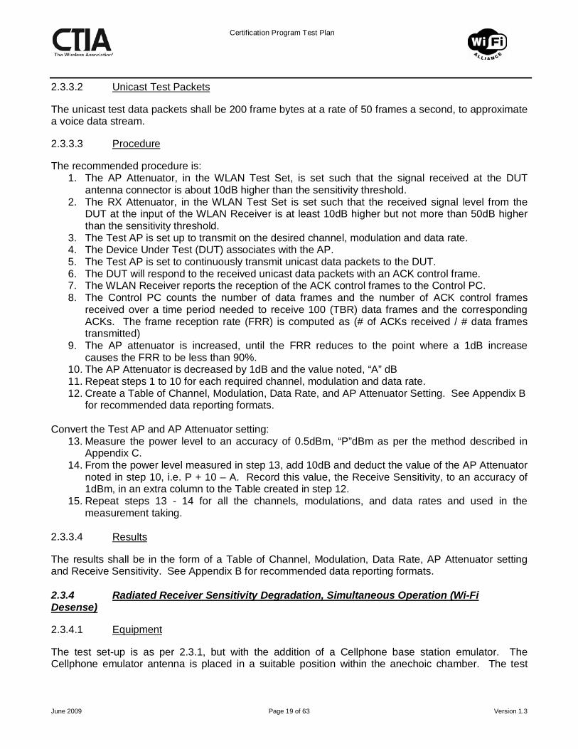
The unicast test data packets shall be 200 frame bytes at a rate of 50 frames a second, to approximate a voice data stream.
Unicast Test Packets
2.3.3.3
The recommended procedure is:
Procedure
1. The AP Attenuator, in the WLAN Test Set, is set such that the signal received at the DUT antenna connector is about 10dB higher than the sensitivity threshold.
2. The RX Attenuator, in the WLAN Test Set is set such that the received signal level from the DUT at the input of the WLAN Receiver is at least 10dB higher but not more than 50dB higher than the sensitivity threshold.
3. The Test AP is set up to transmit on the desired channel, modulation and data rate. 4. The Device Under Test (DUT) associates with the AP. 5. The Test AP is set to continuously transmit unicast data packets to the DUT. 6. The DUT will respond to the received unicast data packets with an ACK control frame. 7. The WLAN Receiver reports the reception of the ACK control frames to the Control PC. 8. The Control PC counts the number of data frames and the number of ACK control frames
received over a time period needed to receive 100 (TBR) data frames and the corresponding ACKs. The frame reception rate (FRR) is computed as (# of ACKs received / # data frames transmitted)
9. The AP attenuator is increased, until the FRR reduces to the point where a 1dB increase causes the FRR to be less than 90%.
10. The AP Attenuator is decreased by 1dB and the value noted, “A” dB 11. Repeat steps 1 to 10 for each required channel, modulation and data rate. 12. Create a Table of Channel, Modulation, Data Rate, and AP Attenuator Setting. See Appendix B
for recommended data reporting formats. Convert the Test AP and AP Attenuator setting:
13. Measure the power level to an accuracy of 0.5dBm, “P”dBm as per the method described in Appendix C.
14. From the power level measured in step 13, add 10dB and deduct the value of the AP Attenuator noted in step 10, i.e. P + 10 – A. Record this value, the Receive Sensitivity, to an accuracy of 1dBm, in an extra column to the Table created in step 12.
15. Repeat steps 13 - 14 for all the channels, modulations, and data rates and used in the measurement taking.
2.3.3.4
The results shall be in the form of a Table of Channel, Modulation, Data Rate, AP Attenuator setting and Receive Sensitivity. See Appendix B for recommended data reporting formats.
Results
2.3.4
2.3.4.1
Radiated Receiver Sensitivity Degradation, Simultaneous Operation (Wi-Fi Desense)
The test set-up is as per 2.3.1, but with the addition of a Cellphone base station emulator. The Cellphone emulator antenna is placed in a suitable position within the anechoic chamber. The test
Equipment

Certification Program Test Plan
June 2009 Page 20 of 63 Version 1.3
shall be carried out at only one position of the test antenna that corresponds to the maximum radiation of the DUT as determined in the TRP and TIS measurements. Wi-Fi desense shall be measured free-space only.
2.3.4.2
The unicast test data packets shall be 200 frame bytes at a rate of 50 frames a second, to approximate a voice data stream.
Unicast Test Packets
2.3.4.3
The recommended procedure is:
Procedure
1. The AP Attenuator, in the WLAN Test Set, is set such that the signal received at the DUT antenna connector is about 10dB higher than the sensitivity threshold.
2. The RX Attenuator, in the WLAN Test Set is set such that the received signal level from the DUT at the input of the WLAN Receiver is at least 10dB higher but not more than 50dB higher than the sensitivity threshold.
3. The Test AP is set up to transmit on the desired channel, modulation and data rate. 4. The Device Under Test (DUT) associates with the AP. 5. The Test AP is set to continuously transmit unicast data packets to the DUT. 6. The DUT will respond to the received unicast data packets with an ACK control frame. 7. The WLAN Receiver reports the reception of the ACK control frames to the Control PC and the
number of ACK frames per second is noted. 8. The Control PC counts the number of data frames and the number of ACK control frames
received over a time period needed to receive 100 (TBR) data frames and the corresponding ACKs. The frame reception rate (FRR) is computed as (# of ACKs received / # data frames transmitted)
9. The AP attenuator is increased, until the FRR reduces to the point where a 1dB increase causes the FRR to be less than 90%.
10. The AP Attenuator is decreased by 1dB and the value noted, “A”dB 11. The cellphone of the converged device is then activated, and using the Cellular Base Station,
the device is made to simulate being in a standard voice call. The cellular phone shall be made to transmit at the highest power.
12. The AP Attenuator is then decreased, until the FRR is at the point where a 1dB increase causes the FRR to be less than 90%.
13. The AP Attenuator is decreased by 1dB and the value noted, “B”dB. 14. The Receive Sensitivity degradation is then calculated by subtracting the reading noted in step
10 from the reading noted in step 13, i.e. Receive sensitivity degradation is “B-A” dB. Note the Receive Degradation value.
15. Repeat steps 3 to 14 for each required channel, modulation and data rate. 16. Create a Table of Channel, Modulation, Data Rate and Receive Degradation.
2.3.5
2.3.5.1
Radiated Cellular Receiver Sensitivity Degradation, Simultaneous Operation (Cellular Desense)
The test set up is shown in figure 2.4, where the Converged Device and the Access Point antenna are placed in a suitable position within an anechoic chamber. The test shall be carried out at only one position of the test antenna that corresponds to the maximum receive sensitivity (Reference
Equipment

Certification Program Test Plan
June 2009 Page 21 of 63 Version 1.3
Polarization and Orientation Position) as determined in the TIS, free space, full channel, cellular DUT measurement. If the DUT’s cellular radio has not been tested previously, then a reference TIS measurement must also be made in the free-space configuration to determine the reference value and position.
Figure 2.4 – Test Configuration – Cellular Desense due to Wi-Fi
2.3.5.2
Wi-Fi DUT Transmitter Stimulus
Continuous short unicast UDP packets are transmitted by the Access Point using the MAC address of the Wi-Fi DUT. The DUT will respond with continuous ACKs which will be transmitted at maximum power. A traffic generator runs on the PC AP Controller, and generates continuous unicast packets. The traffic generator software is available from the Wi-Fi Alliance web site as an executable. The AP Tx/Rx analog output is connected to the antenna, inside the chamber, using a variable attenuator4. The purpose of the attenuator is to make sure that the transmit signal from the AP does not impact the relative sensitivity measurement in the DUT. If the DUT is an 802.11b device the ACKs will be transmitted at 1 Mbps (long preamble5). With the AP data rate set to “auto” the AP transmitted data will be 11 Mbps. This setup will achieve a repetition time of approximately 630 µs6
. If the DUT is an 802.11g or an 802.11a device the ACKs will be transmitted at 6 Mbps. With the AP data rate set to “auto” the transmitted data from the AP will be 54 Mbps. This setup will achieve a repetition time of approximately 165 µs.
4 Sufficient attenuation to stop the AP Tx compromising relative sensitivity measurements, but allows DUT to run at desired data rate (maximum attenuation 30 dB). 5 Using short preamble the repetition rate will be approximately 400 µs. 6 Using short preamble the repetition time will be approximately 400 µs.

Certification Program Test Plan
June 2009 Page 22 of 63 Version 1.3
2.3.5.3
TIS testing needs to be performed for the antenna in retracted and extended position if applicable. Follow the set up and test procedure described in section 6 of the CTIA “Test Plan for Mobile Station Over-The Air Performance” version 2.1, for the modulation to be tested.
Procedure
1. Make the Cellular receiver sensitivity measurement, on three channels (low, middle, high), with the Wi-Fi radio off. Record the values.
2. Turn on the Wi-Fi radio and let the Wi-Fi DUT associate with the AP using appropriate settings of the DUT and AP7
3. Start the traffic generator on the PC AP Controller to stimulate the Wi-Fi DUT transmitter.
. Use transmitter stimulus described in section 2.3.5.2 of this document.
4. The traffic generator will initially carry out a ping test on the DUT. If the ping response is good then UDP packet generation commences either on a continuous or for a pre-defined number basis. At the end of the packet generation a final ping test is carried out.
5. Increase the cellular base station emulator transmit power by 5 dB. 6. Make the Cellular relative receiver sensitivity8
7. Relative sensitivity measurements shall be repeated on all or any combination of intermediate channels, provided that the 500 kHz maximum separation rule is followed.
measurement with the Wi-Fi radio on following the procedure described in section 6 corresponding to the modulation of the DUT.
8. Record results. See Appendix B for recommended data reporting formats.
7 AP IP Address 10.10.2.10, DUT IP Address 10.10.2.12, no security, set AP to appropriate channel #, Power save mode off in the DUT, Auto data rate, do not select mixed mode (only b or g or a), select AP to short preamble mode. 8 Relative sensitivity is measured by moving the DUT positioner to the reference polarization and orientation position (best radiated receiver sensitivity). Choose the appropriate polarization and orientation settings that are closest in frequency (low, middle, high band) with frequency being measured. Using base station emulator, measure the appropriate Digital Error Rate as defined in sections 6.2 (CDMA), 6.3 (TDMA), 6.4 (GSM) of the CTIA Test Plan for Mobile Station Over the Air Performance [1], for the cellular modulation to be tested.

Certification Program Test Plan
June 2009 Page 23 of 63 Version 1.3
3. WLAN ACCESS POINT TESTING METHODOLOGY The test set-up and equipment is similar to that used for the Client testing.
3.1
3.1.1
Conducted RF Tests
The basic test set-up is shown in Figure 3.1. The Access Point under test (APUT) is controlled by the PC, through the Ethernet port. The WLAN Station is simply used to communicate with the APUT. The validation of the WLAN Station is similar to that required for the Test AP.
Test Set-up
Figure 3.1 – Block Schematic Diagram – Conducted RF Test for AP
3.1.2
The APUT shall be provided with facilities that enable the Control PC to set the SSID, channel, modulation and data rate.
Equipment
3.1.3
3.1.3.1
Transmit Power Measurement
The unicast test data packets shall be 200 frame bytes at a rate of 50 frames a second, to approximate a voice data stream.
Unicast Test Packets
3.1.3.2
The recommended procedure is:
Test Procedure
1. The AP Attenuator is set such that the signal received at the WLAN APUT’s antenna connector is at least 10dB higher than the sensitivity threshold.
2. The RX Attenuator, in the WLAN Test Set is set such that the received signal level from the APUT at the input of the WLAN Receiver is at least 10dB higher but not more than 50dB higher than the sensitivity threshold.
3. The AP under test (APUT) is set up to transmit on the desired channel, modulation and at the desired data rate.
4. The WLAN Station, in the WLAN Test Set, associates with the APUT.

Certification Program Test Plan
June 2009 Page 24 of 63 Version 1.3
5. The WLAN Station is set to continuously transmit unicast test data packets to the APUT, which responds with ACK control packets.
6. The WLAN Receiver reports the reception of the APUT ACK transmissions together with the data rate and the RSSI reading to the Control PC. Note the mean value of RSSI over a period of about 10 seconds.
7. Repeat steps 3 to 6 for each required channel and data rate. 8. Create a Table of Channel, Modulation, Data Rate and Mean RSSI for each measurement.
See Appendix B for recommended data reporting formats. Convert RSSI Readings:
9. Disconnect the cable to the APUT and connect it to the input of a Vector Signal Generator capable of generating WLAN IEEE 802.11a/b/g frames.
10. Set the Signal Generator to send a WLAN ACK control frame, on the desired center frequency, with the correct modulation and data rate as per the first measurement in the Table created in step 8.
11. Set the WLAN Receiver to the same channel as the Signal Generator. 12. Monitor the RSSI reported by the WLAN Receiver. 13. Adjust the Signal Generator output level such that the RSSI reported by the WLAN Receiver is
that recorded in the corresponding Receive Sensitivity measurement in the Table created in step 8, and record the Output Level of the Signal Generator, to the nearest dBm, in an extra column of the Table.
Note: To reduce the required output level of the Signal Generator, the RX Attenuator may be decreased in value and the difference accounted for in the tabulated results.
14. Repeat steps 10 - 13 for all the channels, modulations, and data rates in the Table created in
Step 8. 3.1.3.3
The Results shall be in the form of a Table of Channel, Modulation, Data Rate, Mean RSSI, and Transmit Power dBm. See Appendix B for recommended data reporting formats.
Results
3.1.4
3.1.4.1
Receive Sensitivity Measurement
The unicast test data packets shall be 200 frame bytes at a rate of 50 frames a second, to approximate a voice data stream.
Unicast Test Packets
3.1.4.2
The recommended procedure is:
Test Procedure
1. The AP Attenuator is set such that the signal received at the APUT antenna connector is about 10dB higher than the sensitivity threshold.
2. The RX Attenuator, in the WLAN Test Set is set such that the received signal level from the APUT at the input of the WLAN Receiver is at least 10dB higher but not more than 50dB higher than the sensitivity threshold.
3. The APUT is set up to transmit on the desired channel, modulation and data rate. 4. The WLAN Station, in the WLAN Test Set, associates with the APUT.

Certification Program Test Plan
June 2009 Page 25 of 63 Version 1.3
5. The WLAN Station is set to continuously transmit unicast data packets to the APUT. 6. The APUT will respond to the received unicast data packets with an ACK control frame. 7. The WLAN Receiver reports the reception of the ACK control frames to the Control PC 8. The Control PC counts the number of data frames and the number of ACK control frames
received over a time period needed to receive 100 (TBR) data frames and the corresponding ACKs. The frame reception rate (FRR) is computed as (# of ACKs received / # data frames transmitted)
9. The AP attenuator is increased, until the FRR reduces to the point where a 1dB increase causes the FRR to be less than 90%.
10. The AP Attenuator is decreased by 1dB and the value noted, “A”dB 11. Repeat steps 3 to 10 for each required channel, modulation and data rate. 12. Create a Table of Channel, Modulation, Data Rate, and AP Attenuator Setting. See Appendix
B for recommended data reporting formats. Convert the Test AP and AP Attenuator setting: Convert the Test AP and AP Attenuator setting:
13. Measure the power level to an accuracy of 0.5dBm, “P”dBm as per the method described in Appendix C.
14. From the power level measured in step 13, add 10dB and deduct the value of the AP Attenuator noted in step 9, i.e. “P + 10 – A”. Record this value, the Receive Sensitivity, to an accuracy of 1dBm in an extra column to the Table created in step 11
15. Repeat steps 13 - 14 for all the channels, modulations, and data rates and used in the measurement taking.
3.1.4.3
The results shall be in the form of a Table of Channel, Modulation, Data Rate, AP Attenuator setting and Receive Sensitivity (10%PER). See Appendix B for recommended data reporting formats.
Results
3.2
3.2.1
Radiated RF Tests
The basic test set-up is similar to that for the conducted tests and is shown in Figure 3.2.
Test Set-up
Figure 3.2 – Block Schematic Diagram – Radiated RF Tests for AP

Certification Program Test Plan
June 2009 Page 26 of 63 Version 1.3
3.2.2
The APUT shall be provided with facilities that enable the Control PC to set the SSID, channel, modulation and data rate.
Equipment
3.2.3
3.2.3.1
Radiated Power
The method used is similar to the conducted transmit measurement with the exception that the co-axial connection between the hybrid splitter and the APUT is now made using the APUT antenna(s) and a Validated test antenna. The radiated path loss, from the position of the APUT antenna(s), including the test antenna, shall be calibrated.
Discussion
The procedure described below relates to each individual measurement and will need to be repeated for each position and data rate specified for the device under test. 3.2.3.2
The unicast test data packets shall be 200 frame bytes at a rate of 50 frames a second, to approximate a voice data stream.
Unicast Test Packets
3.2.3.3
The procedure is identical to that of the conducted transmit power measurement. The settings for the AP and WLAN Receiver attenuators will be different due to extra loss of the radiated path.
Test Procedure
The recommended procedure is:
1. The AP Attenuator is set such that the signal received at the WLAN APUT’s antenna connector is at least 10dB higher than the sensitivity threshold.
2. The RX Attenuator, in the WLAN Test Set is set such that the received signal level from the APUT at the input of the WLAN Receiver is at least 10dB higher but not more than 50dB higher than the sensitivity threshold.
3. The AP under test (APUT) is set up to transmit on the desired channel, modulation and at the desired data rate.
4. The WLAN Station, in the WLAN Test Set, associates with the APUT. 5. The WLAN Station is set to continuously transmit unicast test data packets to the APUT, which
responds with ACK control packets. 6. The WLAN Receiver reports the reception of the APUT ACK transmissions together with the
data rate and the RSSI reading to the Control PC. Note the mean value of RSSI over a period of about 10 seconds.
7. Repeat steps 3 to 6 for each required channel and data rate. 8. Create a Table of Channel, Modulation, Data Rate and Mean RSSI for each measurement.
See Appendix B for recommended data reporting formats. Convert RSSI Readings:
9. Remove the APUT. Connect the APUT’s antenna directly to a Vector Signal Generator capable of generating WLAN IEEE 802.11a/b/g frames.

Certification Program Test Plan
June 2009 Page 27 of 63 Version 1.3
10. Set the Signal Generator to send a WLAN ACK control frame, on the desired center frequency, with the correct modulation and data rate as per the first measurement in the Table created in step 8.
11. Set the WLAN Receiver to the same channel as the Signal Generator. 12. Monitor the RSSI reported by the WLAN Receiver. 13. Adjust the Signal Generator output level such that the RSSI reported by the WLAN Receiver is
that recorded in the corresponding Receive Sensitivity measurement in the Table created in step 8, and record the Output Level of the Signal Generator, to the nearest dBm, in an extra column of the Table.
Note: To reduce the required output level of the Signal Generator, the RX Attenuator may be decreased in value and the difference accounted for in the tabulated results.
14. Repeat steps 10 - 13 for all the channels, modulations, and data rates in the Table created in
Step 8. 3.2.3.4
The Results shall be in the form of a Table of Channel, Modulation, Data Rate, Mean RSSI, and Transmit Power dBm. See Appendix B for recommended data reporting formats.
Results
3.2.4
3.2.4.1
Receive Sensitivity Measurement
The method used is similar to the conducted measurement with the exception that the co-axial connection between the hybrid splitter and the DUT is now made using the DUT antenna(s) and a calibrated test antenna. The radiated path loss from the position of the DUT antenna(s), including the test antenna, shall be calibrated.
Discussion
3.2.4.2
The unicast test data packets shall be 200 frame bytes at a rate of 50 frames a second, to approximate a voice data stream.
Unicast Test Packets
3.2.4.3
The recommended procedure is:
Test Procedure
1. The AP Attenuator is set such that the signal received at the APUT antenna connector is about 10dB higher than the sensitivity threshold.
2. The RX Attenuator, in the WLAN Test Set is set such that the received signal level from the APUT at the input of the WLAN Receiver is at least 10dB higher but not more than 50dB higher than the sensitivity threshold.
3. The APUT is set up to transmit on the desired channel, modulation and data rate. 4. The WLAN Station, in the WLAN Test Set, associates with the APUT. 5. The WLAN Station is set to continuously transmit unicast data packets to the APUT. 6. The APUT will respond to the received unicast data packets with an ACK control frame. 7. The WLAN Receiver reports the reception of the ACK control frames to the Control PC 8. The Control PC counts the number of data frames and the number of ACK control frames
received over a time period needed to receive 100 (TBR) data frames and the corresponding

Certification Program Test Plan
June 2009 Page 28 of 63 Version 1.3
ACKs. The frame reception rate (FRR) is computed as (# of ACKs received / # data frames transmitted)
9. The AP attenuator is increased, until the FRR reduces to the point where a 1dB increase causes the FRR to be less than 90%.
10. The AP Attenuator is decreased by 1dB and the value noted, “A”dB 11. Repeat steps 3 to 10 for each required channel, modulation and data rate. 12. Create a Table of Channel, Modulation, Data Rate, and AP Attenuator Setting. See Appendix B
for recommended data reporting formats. Convert the Test AP and AP Attenuator setting: Convert the Test AP and AP Attenuator setting:
13. Measure the power level to an accuracy of 0.5dBm, “P”dBm as per the method described in Appendix C.
14. From the power level measured in step 13, add 10dB and deduct the value of the AP Attenuator noted in step 10, i.e. P + 10 – A. Record this value, the Receive Sensitivity, to an accuracy of 1dBm in an extra column to the Table created in step 12
15. Repeat steps 13 - 14 for all the channels, modulations, and data rates and used in the measurement taking.
3.2.4.4
The results shall be in the form of a Table of Channel, Modulation, Data Rate, AP Attenuator setting and Receive Sensitivity (10%PER). See Appendix B for recommended data reporting formats.
Results

Certification Program Test Plan
June 2009 Page 29 of 63 Version 1.3
4. RADIATED MEASUREMENTS 4.1
The DUT shall be tested under conditions that most closely represent the actual working conditions of the device.
Test Conditions for Device Under Test
If the DUT is a handheld mobile device, then it should be placed on a turntable mounted on a SAM Head Phantom as described in Reference (1), or mounted for free space testing. See Appendix E for handheld product testing requirements.
If the DUT is an AP, it should be placed on its own on the turntable with the antennas in the vertical position, or as specified by the vendor.
If the DUT is a self contained Wi-Fi/Mobile Module with internal antennas, such as a PC Card, then the vendor may choose to
Either
• Supply the DUT together with one of its intended host platforms, e.g. a laptop computer. In this case, the combination should then be placed on the turntable and the results sheet should clearly state the combination that was used in the measurements.
Or
• Test the Module, on its own, mounted in a holder that orientates the module in the position that represents its normal use. In this case the results sheet should clearly state that the test did not include a host device.
Or
• Carry out both tests as above. This is the preferred method, but not mandatory.
If the DUT is a self contained Wi-Fi/Mobile Module without internal antennas, such as a mPCI Card, then the vendor must supply the complete device, which includes the antennas, for testing. No individual module testing is acceptable.
The test results shall include a description, and diagram or photograph of the test conditions used for the device under test.

Certification Program Test Plan
June 2009 Page 30 of 63 Version 1.3
5. MOBILE STATION TESTING 5.1
5.1.1
Transmitter Performance
5.1.1.1
Conducted Power Output
The DUT shall be provided to the Test Laboratory with the facility to connect directly to the RF test equipment. This may be via an existing antenna connector, or it may be a carefully modified unit to allow such connection. In the latter case, it is the responsibility of the supplier of the DUT to ensure that the connection is present and suitable.
DUT Requirements
5.1.1.2
The measurements shall be taken at the lowest, middle
Frequency Channels
9
5.1.1.3
and highest channels supported by the device, in each of the 2.4GHz and 5GHz bands.
On each frequency channel, the transmit power output shall be measured at the following data rates:
Data Rates
IEEE 802.11b 11Mbps
IEEE 802.11g 6, 11, 12 and 24Mbps
IEEE 802.11a 6, 12 and 24Mbps
5.1.1.4
5.1.1.5
Not Used
Results should be represented in dBm and rounded to the closest integer value.
Results
There is no pass / fail criteria.
5.1.2
5.1.2.1
Total Radiated Power (TRP)
The DUT shall be provided in an unmodified state.
DUT Requirements
5.1.2.2
For IEEE 802.11b/g devices the complete TRP measurement is made on Channel 6. Single point measurements are made on the highest and lowest supported channels. The selection of the location for the single point measurement should be chosen on a section of the radiation pattern that is smooth and at or near the maximum transmit power value.
Frequency Channels
9 For 5 GHz bands refer to Appendix D for the middle channel numbers per sub band.

Certification Program Test Plan
June 2009 Page 31 of 63 Version 1.3
For IEEE 802.11a devices the complete TRP measurement is made on the lowest channel of the lowest supported band and on the highest channel of the highest supported band. Single point measurements are made on each sub band at the lowest, middle10
In each case where a complete TRP measurement is made it shall be reported as the Mode Radiated Figure of Merit. In each case where a single point measurement is made it shall be reported as a Mode Radiated Reference Measurement.
, and highest channels. See Appendix D for examples of some commonly supported 5 GHz bands. The selection of the location, the “Reference Position”, for the single point measurement should be chosen on a section of the radiation pattern that is smooth and at or near the maximum transmit power value.
5.1.2.3
On each frequency channels, the transmit power output shall be measured at the following data rates:
Data Rates
IEEE 802.11b 11Mbps
IEEE 802.11g 6Mbps
IEEE 802.11a 6Mbps
5.1.2.4
Results should be represented in dBm and rounded to the closest integer value.
Results
Inferred TRP results from combinations not specifically tested can be derived using the table of conducted TX power results obtained in 5.1.1.5
There is no pass / fail criteria.
5.2
5.2.1
Receiver Performance
5.2.1.1
Conducted Receiver Sensitivity
The DUT shall be provided with the facility to connect directly to the RF test equipment. This may be via an existing antenna connector, or it may be a carefully modified unit to allow such connection. In the latter case, it is the responsibility of the supplier of the DUT to ensure that the connection is present and suitable.
DUT Requirements
If the DUT is operating a combining diversity scheme then a combiner may be used such that the received signal is split between the antenna connections. In this case the splitter must be included when carrying out the validation procedure with the unused port being correctly terminated.
10 Refer to Appendix D for the middle channel numbers per sub band.

Certification Program Test Plan
June 2009 Page 32 of 63 Version 1.3
5.2.1.2
The measurements shall be taken at the lowest, middle
Frequency Channels
11
5.2.1.3
and highest channels supported by the device, in each of the 2.4GHz and 5GHz bands
On each frequency channel, receive sensitivity shall be measured at the following data rates:
Data Rates
IEEE 802.11b 11Mbps
IEEE 802.11g 6, 11, 24 and 54Mbps
IEEE 802.11a 6, 24 and 54Mbps
5.2.1.4
Results should be represented in dBm and rounded to the closest integer value.
Results
There is no pass / fail criteria.
5.2.2
5.2.2.1
Total Isotropic Sensitivity (TIS)
The DUT shall be provided in an unmodified state.
DUT Requirements
5.2.2.2
For IEEE 802.11b/g devices the complete TIS measurement is made on Channel 6. Single point measurements are made on the highest and lowest supported channels. The selection of the location, the “Reference Position”, for the single point measurement should be chosen on a section of the radiation pattern that is smooth and at or near the maximum sensitivity value.
Frequency Channels
For IEEE 802.11a devices the complete TIS measurement is made on the lowest channel of the lowest supported band and on the highest channel of the highest supported band. Single point measurements are made on each sub band at the lowest, middle10, and highest channels. See Appendix D for examples of some commonly supported 5 GHz bands.. The selection of the location, the “Reference Position”, for the single point measurement should be chosen on a section of the radiation pattern that is smooth and at or near the maximum sensitivity value.
In each case where a complete TIS measurement is made it shall be reported as the Mode Sensitivity Figure of Merit. In each case where a single point measurement is made it shall be reported as a Mode Sensitivity Reference Measurement.
5.2.2.3
On each frequency channels, receive sensitivity shall be measured at the following data rates:
Data Rates
11 For 5 GHz bands refer to Appendix D for the middle channel numbers per sub band.

Certification Program Test Plan
June 2009 Page 33 of 63 Version 1.3
IEEE 802.11b 11Mbps
IEEE 802.11g 54Mbps
IEEE 802.11a 54Mbps
5.2.2.4
Results should be represented in dBm and rounded to the closest integer value.
Results
There is no pass / fail criteria.
5.2.3
5.2.3.1
Radiated Receiver Sensitivity, Simultaneous Operation (Wi-Fi Desense)
The DUT shall be provided in an unmodified state.
DUT Requirements
5.2.3.2
While conducting the simultaneous operation mode evaluation, the “Reference Position” for the corresponding Wi-Fi mode, as determined in Test 5.2.2, shall be used.
Positions
5.2.3.3
The device shall be set to operate at the highest cellular channel supported.
Highest Cellular Frequency Channel Test
The Wi-Fi channel and data rate shall be set as shown in Table 5.1:
Table 5.1 – Wi-Fi Channel and Data Rate for TIS Wi-Fi Desense Wi-Fi Mode Channel Data
Rate IEEE 802.11b 6 11 IEEE 802.11g 54 IEEE 802.11a Middle12 54 of each
supported band
The Radiated Receiver Sensitivity Degradation shall be measured and recorded.
5.2.3.4
Reference shall be made to Appendix A and Tables A.1 and A.2.
Harmonic Interference Tests
For each cellular system supported by the device, the possible harmonic interferences are identified in Tables A1 and A2 for the 2.4GHz and 5GHz Wi-Fi bands respectively.
12 Refer to Apppendix D for the middle channel numbers per sub band.
Certification Program Test Plan
June 2009 Page 34 of 63 Version 1.3
5.2.3.4.1 IEEE 802.11b and .11g
If the device supports IEEE 802.11b or 802.11g, then for each supported combination of cellular system and regulatory domain, reference is made to Table A.1.
• For each supported combination cellular system and regulatory domain 1. Check the column corresponding to that cellular system and regulatory domain 2. If one or more possible harmonic interferences are shown, at supported WI-Fi channels or
regulatory domain, then select one combination – if no combination or no supported combination is shown, no test is required.
3. The Radiated Receiver Sensitivity Degradation shall be measured and recorded against that cellular system
• Select the next supported cellular system and regulatory domain and repeat steps 1, 2 and 3.
5.2.3.4.2 IEEE 802.11a
If the device supports IEEE 802.11a, then for each supported combination of cellular system and regulatory domain, reference is made to Table A.2.
• For each supported combination cellular system and regulatory domain 1. Check the column corresponding to that cellular system and regulatory domain 2. If one or more possible harmonic interferences are shown, at supported WI-Fi channels or
regulatory domain, then select one combination – if no combination or no supported combination is shown, no test is required.
3. The Radiated Receiver Sensitivity Degradation shall be measured and recorded against that cellular system
• Select the next supported cellular system and regulatory domain and repeat steps 1, 2 and 3.
5.2.3.5
Results should be represented in dB and rounded to the closest integer value.
Results
There is no pass / fail criteria.
5.2.4
Radiated Cellular Receiver Sensitivity, Simultaneous Operation (Cellular Desense)
5.2.4.1
DUT Requirements
The DUT shall be provided in an unmodified state. 5.2.4.2
DUT Polarization
While conducting the simultaneous operation measurement, the “Reference Polarization and Orientation” position for the corresponding Cellular mode, as determined in the Cellular TIS measurement, shall be used. There will be three polarization and orientation values, one for each of the three bands (low, middle, high) and the polarization used should be the one closest to the frequency being measured.

Certification Program Test Plan
June 2009 Page 35 of 63 Version 1.3
5.2.4.3
Wi-Fi Frequency
Devices that operate in the 2.4 GHz band will be set to operate on channel 6 (fc = 2.437 GHz). Devices that operate in the 5 GHz band will be set to operate on the mid channel of the appropriate sub-band supported as shown in Table 5.2:
Table 5.2 – Channel setting for Wi-Fi U-NII Band for TIS Cellular Desense
Sub Band Mid Channel # Mid Channel Center Frequency fc
U-NII Lower Band (5.15 GHz to 5.25 GHz)
44 5.200 GHz
U-NII Middle Band (5.25 GHz to 5.35 GHz)
60 5.300 GHz
U-NII Upper Band (5.725 GHz to 5.825 GHz)
157 5.765 GHz
European ETSI Band 120 5.620 GHz If the device has a dual band radio then two sets of cellular desense measurements are required. The relative receiver Sensitivity Degradation shall be measured and recorded. All channels that are above the 5dB margin at the reference sensitivity polarization and orientation position need to be reported. 5.2.4.4
Cellular Technology and Frequency Band
The test shall be repeated for each technology and frequency band supported by the DUT, which may be any combination of the following:
• GSM at 850MHz (GSM 850) • GSM at 900MHz (P-GSM 900) • GSM at 1800MHz (DCS 1800) • GSM at 1900MHz (PCS 1900) • WCDMA at 850MHz (UTRA FDD Operating Band V) • WCDMA at 1900MHz (UTRA FDD Operating Band II) • WCDMA at 2100MHz (UTRA FDD Operating Band I) • CDMA at 850MHz • CDMA at 1900MHz

Certification Program Test Plan
June 2009 Page 36 of 63 Version 1.3
5.2.4.5
Results
Results should be recorded as % Digital Error Rate13
. All channels that are above the 5dB margin at the reference sensitivity polarization need to be reported.
13 Digital Error Rate is a generic term to refer to the appropriate error measuring scheme in 6.2 (CDMA – FER), 6.3 (TDMA – BER) and 6.3 (GSM – RBER) of the CTIA “Test Plan for Mobile Station Over The Air Performance”, Version 2.1.

Certification Program Test Plan
June 2009 Page 37 of 63 Version 1.3
6. ACCESS POINT TESTING 6.1
6.1.1
Transmitter Performance
6.1.1.1
Conducted Power Output
The APUT shall be provided to the Test Laboratory with the facility to connect directly to the RF test equipment. This may be via an existing antenna connector, or it may be a carefully modified unit to allow such connection. In the latter case, it is the responsibility of the supplier of the APUT to ensure that the connection is present and suitable.
APUT Requirements
6.1.1.2
The measurements shall be taken at the lowest, middle
Frequency Channels
14
6.1.1.3
and highest channels supported by the device, in each of the 2.4GHz and 5GHz bands
On each frequency channel, the transmit power output shall be measured at the following data rates:
Data Rates
IEEE 802.11b 11Mbps
IEEE 802.11g 6, 11, 12 and 24Mbps
IEEE 802.11a 6, 12 and 24Mbps
6.1.1.4
6.1.1.5
Not Used
Results should be represented in dBm and rounded to the closest integer value.
Results
There is no pass / fail criteria.
6.1.2
6.1.2.1
Total Radiated Power (TRP)
The APUT shall be provided in an unmodified state.
APUT Requirements
6.1.2.2
For IEEE 802.11b/g devices the complete TRP measurement is made on Channel 6. Single point measurements are made on the highest and lowest supported channels. The selection of the location, the “Reference Position”, for the single point measurement should be chosen on a section of the radiation pattern that is smooth and at or near the maximum transmit power value.
Frequency Channels
14 For 5 GHz bands refer to Appendix D for the middle channel numbers per sub band.

Certification Program Test Plan
June 2009 Page 38 of 63 Version 1.3
For IEEE 802.11a devices the complete TRP measurement is made on the lowest channel of the lowest supported band and on the highest channel of the highest supported band. Single point measurements are made on each sub band at the lowest, middle14, and highest channels. See Appendix D for examples of some commonly supported 5 GHz bands. The selection of the location, the “Reference Position”, for the single point measurement should be chosen on a section of the radiation pattern that is smooth and at or near the maximum transmit power value.
In each case where a complete TRP measurement is made it shall be reported as the Mode Radiated Figure of Merit. In each case where a single point measurement is made it shall be reported as a Mode Radiated Reference Measurement.
6.1.2.3
On each frequency channels, the transmit power output shall be measured at the following data rates:
Data Rates
IEEE 802.11b 11Mbps
IEEE 802.11g 6Mbps
IEEE 802.11a 6Mbps
6.1.2.4
Results should be represented in dBm and rounded to the closest integer value.
Results
Inferred TRP results from combinations not specifically tested can be derived using the table of conducted TX power results obtained in 5.1.1.5
There is no pass / fail criteria.
6.2
6.2.1
Receiver Performance
6.2.1.1
Conducted Receive Sensitivity
The APUT shall be provided with the facility to connect directly to the RF test equipment. This may be via an existing antenna connector, or it may be a carefully modified unit to allow such connection. In the latter case, it is the responsibility of the supplier of the DUT to ensure that the connection is present and suitable.
APUT Requirements
If the APUT is operating a combining diversity scheme then a combiner may be used such that the received signal is split between the antenna connections. In this case the splitter must be included when carrying out the validation procedure with the unused port being correctly terminated.
6.2.1.2
The measurements shall be taken at the lowest, middle
Frequency Channels
15
15 For 5 GHz bands refer to Appendix D for the middle channel numbers per sub band.
and highest channels supported by the device, in each of the 2.4GHz and 5GHz bands

Certification Program Test Plan
June 2009 Page 39 of 63 Version 1.3
6.2.1.3
On each frequency channel, receive sensitivity shall be measured at the following data rates:
Data Rates
IEEE 802.11b 11Mbps
IEEE 802.11g 6, 11, 24 and 54Mbps
IEEE 802.11a 6, 24 and 54Mbps
6.2.1.4
Results should be represented in dBm and rounded to the closest integer value.
Results
There is no pass / fail criteria.
6.2.2
6.2.2.1
Total Isotropic Sensitivity (TIS)
The APUT shall be provided in an unmodified state.
APUT Requirements
6.2.2.2
For IEEE 802.11b/g devices the complete TIS measurement is made on Channel 6. Single point measurements are made on the highest and lowest supported channels. The selection of the location for the single point measurement should be chosen on a section of the radiation pattern that is smooth and at or near the maximum sensitivity value.
Frequency Channels
For IEEE 802.11a devices the complete TIS measurement is made on the lowest channel of the lowest supported band and on the highest channel of the highest supported band. Single point measurements are made on each sub band at the lowest, middle16
In each case where a complete TIS measurement is made it shall be reported as the Mode Sensitivity Figure of Merit. In each case where a single point measurement is made it shall be reported as a Mode Sensitivity Reference Measurement.
, and highest channels. See Appendix D for some commonly supported 5 GHz bands. The selection of the location for the single point measurement should be chosen on a section of the radiation pattern that is smooth and at or near the maximum sensitivity value.
6.2.2.3
On each frequency channels, receive sensitivity shall be measured at the following data rates:
Data Rates
IEEE 802.11b 11Mbps
IEEE 802.11g 54Mbps
16 Refer to Appendix D for the middle channel number per sub band.
Certification Program Test Plan
June 2009 Page 40 of 63 Version 1.3
IEEE 802.11a 54Mbps
6.2.2.4
Results should be represented in dBm and rounded to the closest integer value.
Results
There is no pass / fail criteria.

Certification Program Test Plan
June 2009 Page 41 of 63 Version 1.3
7. WLAN TEST SET 7.1
The estimated signal levels for the various tests are tabulated in Tables 7.1 to 7. 4. From these Tables the requirements for the Test AP TX Power, RX Attenuator and AP Attenuator can be calculated.
Estimated Signal Levels
Table 7.1 – Conducted TX Test
5GHz 2.4GHz OFDM OFDM CCK DUT Min Sensitivity, dBm -65 -65 -76 Margin, dB 10 10 10 Cable loss, dB 6 6 6 Hybrid loss, dB 4 4 4 Required Test AP TX Power, dBm -45 -45 -56 DUT Min TX Power, dBm 17 17 17 DUT Min Antenna Gain, dB -10 -10 -10 Margin, dB 10 10 10 Cable loss, dB 6 6 6 Hybrid loss, dB 4 4 4 RX Signal at RX Attn, dBm -13 -13 -13 WLAN RX Min Sensitivity, dBm -68 -68 -76 RX Attn setting, dB 55 55 63

Certification Program Test Plan
June 2009 Page 42 of 63 Version 1.3
Table 7.2 – Conducted RX Test
5GHz 2.4GHz OFDM OFDM PSK DUT Max Sensitivity, dBm -90 -90 -95 Cable loss, dB 6 6 6 Hybrid loss, dB 4 4 4 Required Test AP TX Power, dBm -80 -80 -85 DUT Max TX Power, dBm 23 23 23 DUT Max Antenna Gain, dB 0 0 0 Margin, dB 10 10 10 Cable loss, dB 6 6 6 Hybrid loss, dB 4 4 4 RX Signal at RX Attn, dBm 3 3 3 WLAN RX Min Sensitivity, dBm -68 -68 -76 RX Attn setting, dB 71 71 79

Certification Program Test Plan
June 2009 Page 43 of 63 Version 1.3
Table 7.3 – Radiated TX Test
5GHz 2.4GHz OFDM OFDM CCK DUT Min Sensitivity, dBm -65 -65 -76
Margin, dB 10 10 10 Required signal level, dBm -55 -55 -66 Distance, m 3.6 1.5 1.5 Path Loss, dB 57.9 43.6 43.6 Test Antenna Gain, dB 10 10 10 Min DUT Antenna Gain, dB -10 -10 -10 Cable loss, dB 3 3 3 Hybrid loss, dB 4 4 4 Required Test AP TX Power,
dBm 9.9 -4.4 -15.4 DUT Min TX Power, dBm 17 17 17 DUT Min Antenna Gain, dB -10 -10 -10 Test Antenna Gain, dB 10 10 10 Path Loss, dB 57.9 43.6 43.6 Margin, dB 10 10 10 Cable loss, dB 3 3 3 Hybrid loss, dB 4 4 4 RX Signal at RX Attn, dBm -57.9 -43.6 -43.6 WLAN RX Min Sensitivity, dBm -68 -68 -76
RX Attn setting, dB 10.1 24.4 32.4

Certification Program Test Plan
June 2009 Page 44 of 63 Version 1.3
Table 7.4 – Radiated RX Test 5GHz 2.4GHz OFDM OFDM PSK DUT Max Sensitivity, dBm -90 -90 -95 DUT Min Antenna Gain, dB -10 -10 -10 Distance, m 3.6 1.5 1.5 Path Loss, dB 57.9 43.6 43.6 Test Antenna Gain, dB 10 10 10 Cable loss, dB 3 3 3 Hybrid loss, dB 4 4 4 Required Test AP TX Power, dBm -25.1 -39.4 -44.4 DUT Min TX Power, dBm 17 17 17 DUT Min Antenna Gain, dB 0 0 0 Test Antenna Gain, dB 10 10 10 Path Loss, dB 57.9 43.6 43.6 Margin, dB 10 10 10 Cable loss, dB 3 3 3 Hybrid loss, dB 4 4 4 RX Signal at RX Attn, dBm -67.9 -53.6 -53.6 WLAN RX Min Sensitivity, dBm -68 -68 -76 RX Attn setting, dB 0.1 14.4 22.4
From these Tables, the following can be calculated:
• AP Attenuator The maximum required Test AP transmit Power is 9.9dBm and the minimum –85dBm Hence the AP Attenuator will need to be at least 95dB
• RX Attenuator The maximum required attenuation is 79dB, and the minimum is 0dB.
7.2
7.2.1
Test AP and WLAN Station Requirements
The Test AP does not require support for encryption, fragmentation or QoS. In addition the Test AP will be set to not support APSD.
Basic Parameters
7.2.2
The basic RF requirements for the Test AP are:
RF Parameters
Standards IEEE 802.11a, 802.11b, 802.11g

Certification Program Test Plan
June 2009 Page 45 of 63 Version 1.3
Signal Rate For IEEE 802.11a/g • 54, 48, 36, 24, 18, 12, 9, 6Mbps
For IEEE 802.11b • 11, 5.5, 2, 1Mbps
Wireless Frequency Range 2.412 to 2.484GHz 4.915 to 5.32 GHz and 5.5 to 5.805GHz Radio and Modulation Type For IEEE 802.11b and 802.11g DSSS
• DBPSK @ 1Mbps • DQPSK @ 2Mbps • CCK @ 5.5 and 11Mbps
For IEEE 802.11a and 802.11g OFDM
• BPSK @ 6 and 9Mbps • QPSK @ 12 and 18Mbps • 16QAM @ 24 and 36Mbps • 64QAM @ 48 and 54Mbps
Minimum Receive Sensitivity For IEEE 802.11a and 802.11g • 6Mbps: -82dBm • 9Mbps: -81dBm • 12Mbps: -79dBm • 18Mbps: -77dBm • 24Mbps: -74dBm • 36Mbps: -70dBm • 48Mbps: -66dBm • 54Mbps: - 65dBm
For IEEE 802.11b and 802.11g • 1Mbps: -86dBm • 2Mbps: -83dBm • 5.5Mbps: -79dBm • 11Mbps: -76dBm
Maximum Transmit Output Power Not less than 10dB at all frequencies and data rates Transmit Relative Constellation Error For OFDM
• 54Mbps: not to exceed –30dB • 48Mbps: not to exceed –27dB • 36Mbps: not to exceed –24dB • 24Mbps: not to exceed –21dB • 18Mbps: not to exceed –18dB • 12Mbps: not to exceed –15dB • 9Mbps: not to exceed – 13dB • 6Mbps: not to exceed – 10dB
7.3
The basic RF requirements for the WLAN Receiver are:
WLAN Receiver RF Requirements
Standards IEEE 802.11a, IEEE 802.11b, IEEE 802.11g Signal Rate For IEEE 802.11a/g
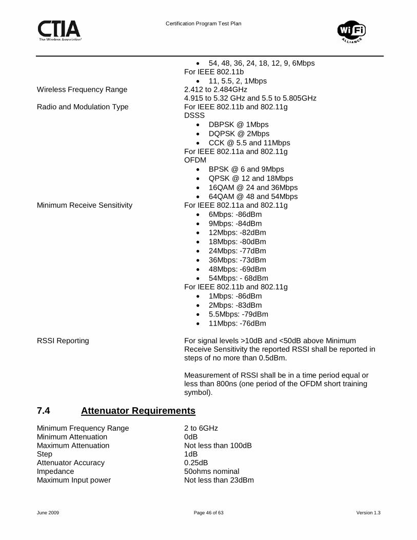
Certification Program Test Plan
June 2009 Page 46 of 63 Version 1.3
• 54, 48, 36, 24, 18, 12, 9, 6Mbps For IEEE 802.11b
• 11, 5.5, 2, 1Mbps Wireless Frequency Range 2.412 to 2.484GHz 4.915 to 5.32 GHz and 5.5 to 5.805GHz Radio and Modulation Type For IEEE 802.11b and 802.11g DSSS
• DBPSK @ 1Mbps • DQPSK @ 2Mbps • CCK @ 5.5 and 11Mbps
For IEEE 802.11a and 802.11g OFDM
• BPSK @ 6 and 9Mbps • QPSK @ 12 and 18Mbps • 16QAM @ 24 and 36Mbps • 64QAM @ 48 and 54Mbps
Minimum Receive Sensitivity For IEEE 802.11a and 802.11g • 6Mbps: -86dBm • 9Mbps: -84dBm • 12Mbps: -82dBm • 18Mbps: -80dBm • 24Mbps: -77dBm • 36Mbps: -73dBm • 48Mbps: -69dBm • 54Mbps: - 68dBm
For IEEE 802.11b and 802.11g • 1Mbps: -86dBm • 2Mbps: -83dBm • 5.5Mbps: -79dBm • 11Mbps: -76dBm
RSSI Reporting For signal levels >10dB and <50dB above Minimum
Receive Sensitivity the reported RSSI shall be reported in steps of no more than 0.5dBm.
Measurement of RSSI shall be in a time period equal or
less than 800ns (one period of the OFDM short training symbol).
7.4
Minimum Frequency Range 2 to 6GHz
Attenuator Requirements
Minimum Attenuation 0dB Maximum Attenuation Not less than 100dB Step 1dB Attenuator Accuracy 0.25dB Impedance 50ohms nominal Maximum Input power Not less than 23dBm

Certification Program Test Plan
June 2009 Page 47 of 63 Version 1.3
Note: For example, the attenuator could consist of two separate switched or programmable attenuators in series; 0-100dB in 10dB steps, and 0-10dB in 1 dB steps.

Certification Program Test Plan
June 2009 Page 48 of 63 Version 1.3
8. APPENDIX A – HARMONIC INTERFERENCE SELECTION MATRICIES The following matrices are to be used for the selection of WLAN / Mobile Device Interference channel pairs. These modes are used in section 5.2.3.4 based upon which modes of operation. All frequencies quoted in the Appendix A Tables are in MHz.
Table A.1 – IEEE 802.11b/g Productsa
Wi-Fi GSM 850 GSM 900 GSM 1800 GSM 1900 CDMA-2000
US/Korea 800 MHz
CDMA-2000 UK
900 MHz
CDMA-2000 Korea
1700MHz
CDMA 2000 US
1900 MHz
UTRA FDD Band I – IV
UTRA TDD All Bands
PHS Asia
iDen 800 MHz
Chan Freq Chan Freq Chan Freq Chan Freq Chan Freq Chan Freq Chan Freq Chan Freq Chan Freq Chan Freq Chan Freq Chan Freq Chan Freq
1 2412 1 806.025
2 2417 1 806.025
3 2422 53 807.325
4 2427 120 809.000
5 2432 187 810.675
6 2437 253 812.325
7 2442 320 814.000
8 2447 387 815.675
9 2452 453 817.325
10 2457 520 819.000
11 2462 991 824.04 587 820.675
12 2467 991 824.04
13 2472 128 824.2 1 825.03
4132b 826.4 991 824.04
14 2484 4162c 832.4
Notes:
a) Interference is caused by 3rd harmonic of the other technology b) UTRA FDD Band V Americas c) UTRA FDD Band VI Japan

Certification Program Test Plan
June 2009 Page 49 of 63 Version 1.3
Table A.2 – IEEE 802.11a Products
Wi-Fi GSM 850 GSM 900 GSM 1800 GSM 1900 CDMA-2000
US/Korea 800 MHz
CDMA-2000 UK
900 MHz
CDMA-2000 Korea
1700MHz
CDMA 2000 US
1900 MHz
UTRA FDD Band I – IV
UTRA TDD All Bands
PHS Asia
iDen 800 MHz
Chan Freq Chan Freq Chan Freq Chan Freq Chan Freq Chan Freq Chan Freq Chan Freq Chan Freq Chan Freq Chan Freq Chan Freq Chan Freq
7 5035 4196e 839.2
8 5040 4200e 840.0
36 5180 594 1726.6 8633c 1726.6
40 5200 628 1733.4 8667c 1733.4
44 5220 661 1740.0 1329 872.0125 8700c 1740.0
48 5240 694 1746.6 1382 873.3375 0 1750.00 8733c 1746.6
52 5260 728 1753.4 1515 876.6625 67 1753.35 8767c 1753.4
56 5280 975 880.2 761 1760.0 1648 879.9875 200 1760.00 8800d 1760.0
60 5300 991 883.4 794 1766.6 1782 883.3375 333 1766.65 8833d 1766.6
64 5320 1007 886.6 828 1773.4 1915 866.6625 467 1773.35 8867d 1773.4
100 5500 1000 914.9875
112 5560 528 1853.4 67 1853.35 9267b 1853.4 9267g 1853.4
116 5580 561 1860.0 200 1860.00 9300b 1860.0 9300g 1860.0
120 5600 594 1866.6 333 1866.65 9333b 1866.6 9333g 1866.6
124 5620 628 1873.4 467 1873.35 9367b 1873.4 9367g 1873.4
128 5640 661 1880.0 600 1880.00 9400b 1880.0 9400g 1880.0
132 5660 694 1886.6 733 1886.65 9433b 1886.6 9433g 1886.6
136 5680 728 1893.4 867 1893.35 9467b 1893.4 9467g 1893.4 1 1895.15
140 5700 761 1900.0 1000 1900.00 9500b 1900.0 9500g 1900.0
17 1899.95 9504j 1900.8
9512f 1902.4
149 5745 9575fij 1915.0
153 5765 9612a 1922.4 9596j 1919.2
9608i 1921.6
157 5785 9642ak
1928.4 9638i 1927.6
9654l 9662h 1932.4
161 5805 9675a 1935.0 9675h 1935.0
165 5825 9708a 1941.6 9708h 1941.6
196 4980 4150e 830.0
Notes: a) UTRA FDD Band I ROW g) UTRA TDD Americas (1850-1910) including LCR b) UTRA FDD Band II Americas h) UTRA TDD Americas (1930-1990) including LCR c) UTRA FDD Band III ROW and UTRA FDD Band IV Americas i) UTRA TDD Americas (1910 – 1930) including LCR d) UTRA FDD Band III ROW j) UTRA TDD LCR ROW (1900 – 1920) e) UTRA FDD Band VI Japan including 10MHz channels k) UTRA TDD LCR Americas (1910-1930) f) UTRA TDD ROW (1900-1920) l) UTRA TDD LCR Americas (1930-1990)

Certification Program Test Plan
June 2009 Page 50 of 63 Version 1.3
9. APPENDIX B – SUMMARY TEST REPORT Table B.1 – Sample Summation
Manufacturer
Model
Wi-Fi Alliance CID17 CTIA Request #
Serial Number/ESN/IMEI
FCC ID Number
Hardware Version
Software Version
TEST 5.1.1 and 6.1.1. Conducted Power Output
Table B.2 – Conducted Power Output Results Mode Channel Data rate, Mbps Result, dBm Comments
IEEE 802.11b
Low 11 Mid 11 High 11
IEEE 802.11g
Low
6 11 12 24
Mid
6 11 12 24
High
6 11 12 24
IEEE 802.11a
Low 6 12 24
Mid18 6 12 24
High 6 12 24
17 Vendor supplies the Wi-FI Alliance CID (Certification Identifier) during the CWG application process. 18 Refer to Appendix D for the middle channel numbers per sub band.

Certification Program Test Plan
June 2009 Page 51 of 63 Version 1.3
TEST 5.1.2 and 6.1.2
Total Radiated Power (TRP) – Mode Radiated Figure of Merit
Table B.3 – Mode Radiated Figure of Merit Results
Mode Channel Data rate, Mbps
Result, dBm
TRP Comments
IEEE 802.11b 6 11 Calculated as per Reference (1)
IEEE 802.11g 6 6 Calculated as per Reference (1)
IEEE 802.11a
Lowest Channel of
Lowest supported
band
6 Calculated as per Reference (1)
IEEE 802.11a
Highest Channel of
Highest supported
band
6 Calculated as per Reference (1)
Radiated Reference Measurements
Table B.4 – Radiated Reference Measurements Results
Mode Channel Data rate, Mbps
Reference Position Transmit Power, dBm Comments
Theta Phi
IEEE 802.11b
6 11
Low 11
High 11
IEEE 802.11g
6 6
Low 6
High 6
IEEE 802.11a
Lowest Channel of Lowest
Supported Band 6

Certification Program Test Plan
June 2009 Page 52 of 63 Version 1.3
Middle Channel of Lowest
Supported Band 6
Highest Channel of Lowest
Supported Band 6
Lowest Channel of Next
Supported Band 6
Middle Channel of Next
Supported Band 6
Highest Channel of Next
Supported Band 6
Lowest Channel of Next
Supported Band 6
Middle Channel of Next
Supported Band 6
Highest Channel of Next
Supported Band 6
Lowest Channel of Highest
Supported Band 6
Middle Channel of Highest
Supported Band 6
Highest Channel of Highest
Supported Band 6

Certification Program Test Plan
June 2009 Page 53 of 63 Version 1.3
TEST 5.2.1 and 6.2.1 Conducted Receiver Sensitivity
Table B.5 – Conducted Receiver Sensitivity Results Mode Channel Data rate,
Mbps Result, dBm Comments
IEEE 802.11b
Low 11 Mid 11 High 11
IEEE 802.11g
Low
6 11 24 54
Mid
6 11 24 54
High
6 11 24 54
IEEE 802.11a
Low 6
24 54
Mid19 6
24 54
High 6
24 54
19 Refer to Appendix D for the middle channel numbers per sub band.
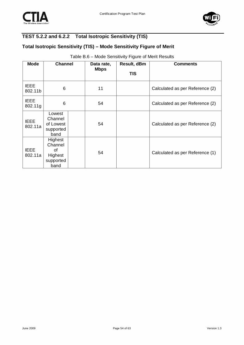
Certification Program Test Plan
June 2009 Page 54 of 63 Version 1.3
TEST 5.2.2 and 6.2.2 Total Isotropic Sensitivity (TIS)
Total Isotropic Sensitivity (TIS) – Mode Sensitivity Figure of Merit
Table B.6 – Mode Sensitivity Figure of Merit Results Mode Channel Data rate,
Mbps Result, dBm
TIS
Comments
IEEE 802.11b 6 11 Calculated as per Reference (2)
IEEE 802.11g 6 54 Calculated as per Reference (2)
IEEE 802.11a
Lowest Channel
of Lowest supported
band
54 Calculated as per Reference (2)
IEEE 802.11a
Highest Channel
of Highest
supported band
54 Calculated as per Reference (1)

Certification Program Test Plan
June 2009 Page 55 of 63 Version 1.3
Sensitivity Reference Measurements
Table B.7 – Sensitivity Reference Measurements Results
Mode Channel Data rate, Mbps
Reference Position Sensitivity,
dBm Comments Theta Phi
IEEE 802.11b
6 11
Low 11
High 11
IEEE 802.11g
6 54
Low 54
High 54
IEEE 802.11a
Lowest Channel of
Lowest Supported
Band
54
Middle Channel of
Lowest Supported
Band
54
Highest Channel of
Lowest Supported
Band
54
Lowest Channel of
Next Supported
Band
54
Middle Channel of
Next Supported
Band
54
Highest Channel of
Next Supported
Band
54

Certification Program Test Plan
June 2009 Page 56 of 63 Version 1.3
Lowest Channel of
Next Supported
Band
54
Middle Channel of
Next Supported
Band
54
Highest Channel of
Next Supported
Band
54
Lowest Channel of
Highest Supported
Band
54
Middle Channel of
Highest Supported
Band
54
Highest Channel of
Highest Supported
Band
54

Certification Program Test Plan
June 2009 Page 57 of 63 Version 1.3
TEST 5.2.3 Radiated Receiver Sensitivity, Simultaneous Operation (Wi-Fi Desense)
Desensitization Reference Measurements
Test 5.2.3.3 Highest Cellular Frequency Channel Test
Table B.8 – Highest Cellular Frequency Channel Test Results
802.11 Highest Cellular Frequency
802.11 Data rate, Mbps
Reference Position Desense
dB Comments Mode Chan Mode Chan Theta Phi
IEEE 802.11b
6 11
IEEE 802.11g
6 54
IEEE 802.11a
Mid 54

Certification Program Test Plan
June 2009 Page 58 of 63 Version 1.3
Test 5.2.3.4 Harmonic Interference Tests
Table B.9 – Harmonic Interference Tests Results 802.11b&g
802.11 Cellular 802.11 Data rate, Mbps
Reference Position Desense,
dB Comments Mode Channel Cellular
Mode Chan Theta Phi
IEEE 802.11
b
11
IEEE 802.11
g
54
Table B.10 – Harmonic Interference Tests Results 802.11a
802.11 Cellular 802.11 Data rate, Mbps
Reference Position Desense,
dB Comments Mode Chan Mode Chan Theta Phi
IEEE 802.11a
54

Certification Program Test Plan
June 2009 Page 59 of 63 Version 1.3
Test 5.2.4 Relative Receiver Sensitivity, Simultaneous Operation (Cellular Desense)
5.2.4.1 Wi-Fi 2.4 GHz Band
Table B.11 – Cellular Desense Test Results for 802.11b&g Operation Cellular
Technology
XXXX
Wi-Fi Channel
Reference Position Thetao
Reference Position
Phio
FER % Comments
Low 802.11b/g Ch. 6
(2.437GHz)
Low + 500 kHz
802.11b/g Ch. 6
(2.437GHz)
Low + 1000 kHz
802.11b/g Ch. 6
(2.437GHz)
Low + 1500 kHz
802.11b/g Ch. 6
(2.437GHz)
Low + 2000 kHz
802.11b/g Ch. 6
(2.437GHz)
Low + 2500 kHz
802.11b/g Ch. 6
(2.437GHz)
Low + 3000 kHz
802.11b/g Ch. 6
(2.437GHz)
Low + 3500 kHz
802.11b/g Ch. 6
(2.437GHz)
Low + xxxx kHz
802.11b/g Ch. 6
(2.437GHz)

Certification Program Test Plan
June 2009 Page 60 of 63 Version 1.3
5.2.4.2 Wi-Fi U-NII Middle Band GHz Band
Table B.12 – Cellular Desense Test Results for 802.11a Operation Cellular
Technology
XXXX
Wi-Fi Channel Reference Position Thetao
Reference Position
Phio
FER % Comments
Low 802.11a Ch. 60
(5.300 GHz)
Low + 500 kHz
802.11a Ch. 60
(5.300 GHz)
Low + 1000 kHz
802.11a Ch. 60
(5.300 GHz)
Low + 1500 kHz
802.11a Ch. 60
(5.300 GHz)
Low + 2000 kHz
802.11a Ch. 60
(5.300 GHz)
Low + 2500 kHz
802.11a Ch. 60
(5.300 GHz)
Low + 3000 kHz
802.11a Ch. 60
(5.300 GHz)
Low + 3500 kHz
802.11a Ch. 60
(5.300 GHz)
Low + xxxx kHz
802.11a Ch. 60
(5.300 GHz)

Certification Program Test Plan
June 2009 Page 61 of 63 Version 1.3
10. APPENDIX C – RF POWER MEASUREMENT The following method shall be used in the conversion of the Test AP and AP Attenuator settings to a power level in dBm.
1. Remove the DUT and connect in its place the input of a matched diode detector or equivalent thereof. The output of the detector shall be connected to the vertical channel of an oscilloscope.
a. The combination of the diode detector and the oscilloscope shall be capable of faithfully reproducing the duty cycle of the transmitted output signal.
b. The observed duty cycle (Tx on / Tx on + off) shall be noted as x (0 < x ≤1). 2. Replace the matched diode detector with a wideband calibrated RF power meter with a
matched thermocouple detector or an equivalent thereof and with an integration period that exceeds the repetition period of the transmitter by a factor 5 or more.
3. Set the Test AP to transmit on the same channel, modulation and data rate as the first row of the Table created in step 11.
4. Set the AP Attenuator to 10dB. 5. Set the AP to continuously transmit unicast data packets. 6. Measure the power level, “A”dBm. 7. Record the power level, to an accuracy of 0.5dBm, “P”dBm
where P = A + 10 log (1/x) dBm. Note: This test procedure is similar to that specified in ETSI EN 301 893 V1.3.1.

Certification Program Test Plan
June 2009 Page 62 of 63 Version 1.3
11. APPENDIX D – IEEE 802.11A SUPPORTED CHANNEL OPTION EXAMPLES
Sub Band
Channel Range
Comments TIS/TRP Channel
Reference Channel
Middle Channel Number
Option One – All UNII Bands UNII Low Band
36 to 48 Lowest Band 36 (36), 44, 48 44
UNII Middle Band
52 to 64 Next Highest Band
- 52, 60, 64 60
UNII Upper Band
149 to 161
Highest Band
161
149, 157, (161)
157
Option Two – All UNII and ETSI Bands UNII Low Band
36 to 48 Lowest Band 36 (36), 44, 48 44
UNII Middle Band
52 to 64 Next Highest Band
- 52, 60, 64 60
ETSI European band
100 to 140
Next Highest Band
- 100, 120, 140
120
UNII Upper Band
149 to 161
Highest Band
161
149, 157, (161)
157
Option Three – ETSI Band Only ETSI European band
100 to 140
One Band 100, 140 (100), 120, (140)
120
Option Four – All UNII Bands and Channel 165 UNII Low Band
36 to 48 Lowest Band 36 (36), 44, 48 44
UNII Middle Band
52 to 64 Next Highest Band
- 52, 60, 64 60
UNII Upper Band
149 to 161
Next Highest Band
-
149, 157, 161
157
USA 165 Highest Band
165 (165) -
Option Five - Lower Two UNII Bands UNII Low Band
36 to 48 Lowest Band 36 (36), 44, 48 44
UNII Mid Band
52 to 64 Highest Band
64 52, 60, (64) 60

Certification Program Test Plan
June 2009 Page 63 of 63 Version 1.3
12. APPENDIX E – DEVICE TESTING CONFIGURATIONS Converged handheld devices that have moveable keyboards shall be tested with keyboard open, closed, or any other operational configurations as outlined in the table below.
Device Capabilities
TIS/TRP Tx/Rx Reference Wi-Fi Desense Cellular Desense
Wi-Fi Browser + Cellular Voice
Free Space with all intended mechanical modes (including keyboard closed)
Free Space with all intended mechanical modes (including keyboard closed)
Free Space with one operational mechanical mode (preferably slider closed)
Free Space with one operational mechanical mode (preferably slider closed)
Wi-Fi Browser + Wi-Fi VoIP + Cellular Voice
SAM Right Ear with one mechanical position supporting Wi-Fi VoIP (keyboard closed) + Free Space with all intended mechanical modes (including keyboard closed)
SAM Right Ear with one mechanical position supporting Wi-Fi VoIP (keyboard closed) + Free Space with all intended mechanical modes (including keyboard closed)
Free Space with one operational mechanical mode (preferably slider closed)
Free Space with one operational mechanical mode (preferably slider closed)
Note: Mechanical modes can mean keyboard slider in all positions; open, closed, slider half rotated 90o, or other keyboard positions depending on product configuration.
- End -