WavePro LT - GE Industrial Solutions · WavePro LT Busway System ... GE is the only company listed...
44
WavePro LT Busway System
Transcript of WavePro LT - GE Industrial Solutions · WavePro LT Busway System ... GE is the only company listed...
WavePro LTBusway System
REGIONAL OFFICES
NORTH
BRANCH OFFICES
Gurgaon
GE India Industrial Pvt. Ltd.5th Floor, Building No.7A DLF Cyber City, DLF Phase-IIISector 25 A, GurgaonHaryana – 122002Ph: (0124) 4808000Fax: (0124) 4226911 / 4226912
Chandigarh
GE India Industrial Pvt. Ltd.SCO No. 72 & 73, First FloorSector 8/C, Madhya MargChandigarh-160008Ph: (0172) 3982908-10Fax: (0172) 3982905
Lucknow
GE India Industrial Pvt. Ltd.101, Ace Business Center19, Vidhan Sabha MargLucknow-226001Ph: (0522) 3203808, 3012444/666Fax: (0522) 4045909
SOUTH
Bangalore
GE India Industrial Pvt. Ltd.The Millenia, Level-6, Tower B1 & 2, Murphy Road, UlsoorBangalore-560008Ph: (080) 41434000Fax: (080) 41434199
Chennai
GE India Industrial Pvt. Ltd.Temple Tower, 6th Floor476, (New No. 672) Anna SalaiNandanamChennai-600035Ph: (044) 45070470-84Fax: (044) 45070474
Coimbatore
GE India Industrial Pvt. Ltd.No.36/6 & 7, 1st FloorAshirwad BuildingD.B.Road, R.S. PuramCoimbatore-641002Ph: (0422) 4393520 / 4393529
WEST
Mumbai
GE India Industrial Pvt. Ltd.361/362, Solitaire Corporate ParkM. Vasanji Road, ChakalaAndheri (E), Mumbai-400093Ph: (022) 40101610Fax: (022) 40101611
EAST
Kolkata
GE India Industrial Pvt. Ltd.Horizon Building, 4th Floor 57, Chowringhee RoadKolkata-700071Ph: (033) 40034056Fax: (033) 40034071
Works:GE India Industrial Pvt. Ltd.Plot No. 42/1 & 45/14Electronic City - Phase IIBangalore-560100Ph: (080) 41113000Fax: (080) 28528469/552
HO:GE India Industrial Pvt. Ltd.The Millenia, Level-6, Tower B1 & 2, Murphy Road, UlsoorBangalore-560008Ph: (080) 41434000Fax: (080) 41434199Email: [email protected]
Toll Free No:18001024343
Customer Care:[email protected]
g and General Electric are registered trade marks of General Electric Co. USA©
Ahmedabad
GE India Industrial Pvt. Ltd.405-406, Kirtiman ComplexKinariwala House, Behind CitibankOff C.G. Road, Ahmedabad-380006Ph: (079) 65427385/65427389Fax: (079) 26460637
Pune
GE Money Financial Services LimitedShop No. 405-410, 4th FloorCity Point, Dhole Patil RoadPune-411001Ph: (020) 41266999Fax: (020) 41266109
Cochin
GE India Industrial Pvt. Ltd.Mayur Business Center & MotelChittur Road, Pullepadi JunctionCochin-682035Ph: (0484) 2364139Fax: (0484) 4031400
Hyderabad
GE India Industrial Pvt. Ltd.5-2-45, Hyderbasti, RP RoadNear Gujarati High SchoolSecunderabad-500003Ph: (040) 27543162, 66311264Fax: (040) 66339272
We are committed to continuous development and improvement of our products and the specifications aresubject to change without notice. For product availability and latest prices, please contact GE Sales Team.
For any further information, visit us at http://www.geindustrial.com
GE
Industrial Solutions
2010 World's Most Innovative Companies
2008 World’s Most Respected Companies 2007 World’s Best R&D Companies
2011 World’s Most Admired Companies
2011 Best Global Brand
2009 World’s Most Respected Companies
GE is a diversified organization covering a myriad of market segments, including infrastructure, finance and media.
From energy, water, transportation and health to access to money and information, GE serves customers in more than
100 countries and employs more than 300,000 people worldwide.
The company traces its beginnings from Thomas A. Edison, who established the Edison Electric Light Company in 1878.
In 1892, a merger of Edison General Electric Company and Thomson-Houston Electric Company created the General
Electric Company. GE is the only company listed in the Dow Jones Industrial Index today that was also included in the
original index in 1896.
GE Industrial Solutions, a division of GE Energy, is a global leading provider in power distribution, offering a wide range
of products which includes medium and low voltage power distribution equipments and components, and motor &
control systems that are safe, reliable and offer high performance. Its innovative solutions can improve energy
efficiency and environmental impact in power plants, power grids, oil & gas, mining, data center, overseas EPC,
industrial manufacturing, rail transportation, commercial buildings, residential houses, renewable energy and many
other industries.
GE is one of the worldwide partners of the Olympic Games. In 2008, GE assisted Beijing with this tremendous event, which was unprecedented in scale and first-class in its use of science and technology, offering a series of innovative solutions and products for around 400 Olympic infrastructure projects, covering fields in electricity distribution, lighting, security, water processing, benefiting some 37 Olympic venues and 168 commercial buildings. GE also brought its experiences to the 2010 Expo in Shanghai, Asia Games in Guangzhou, Vancouver Olympic Games and will continue through to the London 2012 Olympic Games.

1
Quick Index
Reference Standards & Certificates
System Overview
Features of WavePro LT Busway System
Product Advantages
Cable and Wire Conversion
Electrical Characteristics
Grounding bar resistance of WavePro LT busway system
Short-circuit current ratings
Ambient temperature's influence on application
Resistance, reactance, impedance and voltage drop
Physical Data
Straight length
Plug-in straight length
Joint
Fittings
Fittings data
Flanged end
Flanged end details
End tap box and terminal cover
Flanged end cutout and hole pattern
Resistance to Flame Propagation, Fire Proofing
Wall flange
Bus plug
Accessories
Application
Installation
Ordering Information
Catalog Numbering System
1
2
3
4-5
6-7
8-9
10
10
11
11
12
13
13
14
15
16-17
18-21
22-23
24
25
26
28
29
30
31-32
33
34-37
38-39
40-41
Quick IndexGE
Industrial Solutions
2010 World's Most Innovative Companies
2008 World’s Most Respected Companies 2007 World’s Best R&D Companies
2011 World’s Most Admired Companies
2011 Best Global Brand
2009 World’s Most Respected Companies
GE is a diversified organization covering a myriad of market segments, including infrastructure, finance and media.
From energy, water, transportation and health to access to money and information, GE serves customers in more than
100 countries and employs more than 300,000 people worldwide.
The company traces its beginnings from Thomas A. Edison, who established the Edison Electric Light Company in 1878.
In 1892, a merger of Edison General Electric Company and Thomson-Houston Electric Company created the General
Electric Company. GE is the only company listed in the Dow Jones Industrial Index today that was also included in the
original index in 1896.
GE Industrial Solutions, a division of GE Energy, is a global leading provider in power distribution, offering a wide range
of products which includes medium and low voltage power distribution equipments and components, and motor &
control systems that are safe, reliable and offer high performance. Its innovative solutions can improve energy
efficiency and environmental impact in power plants, power grids, oil & gas, mining, data center, overseas EPC,
industrial manufacturing, rail transportation, commercial buildings, residential houses, renewable energy and many
other industries.
GE is one of the worldwide partners of the Olympic Games. In 2008, GE assisted Beijing with this tremendous event, which was unprecedented in scale and first-class in its use of science and technology, offering a series of innovative solutions and products for around 400 Olympic infrastructure projects, covering fields in electricity distribution, lighting, security, water processing, benefiting some 37 Olympic venues and 168 commercial buildings. GE also brought its experiences to the 2010 Expo in Shanghai, Asia Games in Guangzhou, Vancouver Olympic Games and will continue through to the London 2012 Olympic Games.
2
Reference Standards
Certificates
WavePro LT busway system complies with:
IEC 60439-1IEC 60439-2IEC 60529
GB 7251.1GB 7251.2
GE's WavePro LT Busway System provides safe and reliable electrical distribution in commercial and industrial applications. WavePro LT Busway System reduces installation cost while providing superior performance for electrical contractors and end users.
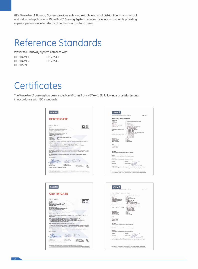
The WavePro LT busway has been issued certificates from KEMA-KUER, following successful testing in accordance with IEC standards.
3
System Overview
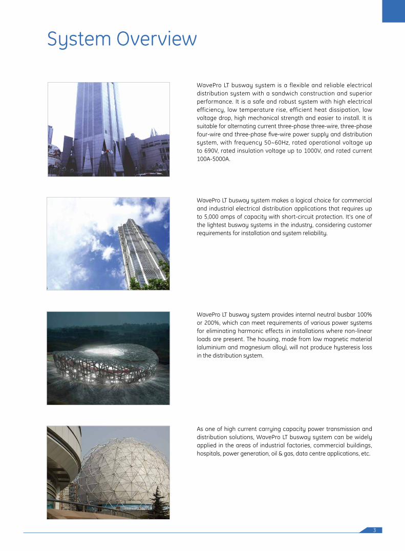
WavePro LT busway system is a flexible and reliable electrical distribution system with a sandwich construction and superior performance. It is a safe and robust system with high electrical efficiency, low temperature rise, efficient heat dissipation, low voltage drop, high mechanical strength and easier to install. It is suitable for alternating current three-phase three-wire, three-phase four-wire and three-phase five-wire power supply and distribution system, with frequency 50~60Hz, rated operational voltage up to 690V, rated insulation voltage up to 1000V, and rated current 100A-5000A.
WavePro LT busway system makes a logical choice for commercial and industrial electrical distribution applications that requires up to 5,000 amps of capacity with short-circuit protection. It's one of the lightest busway systems in the industry, considering customer requirements for installation and system reliability.
WavePro LT busway system provides internal neutral busbar 100% or 200%, which can meet requirements of various power systems for eliminating harmonic effects in installations where non-linear loads are present. The housing, made from low magnetic material (aluminium and magnesium alloy), will not produce hysteresis loss in the distribution system.
As one of high current carrying capacity power transmission and distribution solutions, WavePro LT busway system can be widely applied in the areas of industrial factories, commercial buildings, hospitals, power generation, oil & gas, data centre applications, etc.
4
Features of WavePro LTBusway System
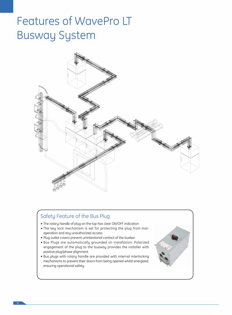
Safety Feature of the Bus Plug• The rotary handle of plug on the top has clear ON/OFF indication• The key lock mechanism is set for protecting the plug from mal-
operation and any unauthorized access• Plug outlet covers prevent unintentional contact of the busbar• Bus Plugs are automatically grounded on installation. Polarized
engagement of the plug to the busway provides the installer with positive plug/phase alignment
• Bus plugs with rotary handle are provided with internal interlocking mechanisms to prevent their doors from being opened whilst energized, ensuring operational safety
5
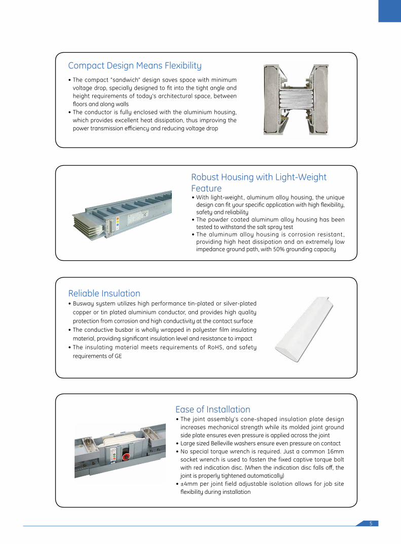
Compact Design Means Flexibility• The compact "sandwich" design saves space with minimum
voltage drop, specially designed to fit into the tight angle and height requirements of today's architectural space, between floors and along walls
• The conductor is fully enclosed with the aluminium housing, which provides excellent heat dissipation, thus improving the power transmission efficiency and reducing voltage drop
Robust Housing with Light-Weight Feature• With light-weight , aluminum alloy housing, the unique
design can fit your specific application with high flexibility, safety and reliability
• The powder coated aluminum alloy housing has been tested to withstand the salt spray test
• The aluminum alloy housing is corrosion resistant , providing high heat dissipation and an extremely low impedance ground path, with 50% grounding capacity
Reliable Insulation• Busway system utilizes high performance tin-plated or silver-plated
copper or tin plated aluminium conductor, and provides high quality protection from corrosion and high conductivity at the contact surface
• The conductive busbar is wholly wrapped in polyester film insulating material, providing significant insulation level and resistance to impact
• The insulating material meets requirements of RoHS, and safety requirements of GE
Ease of Installation• The joint assembly's cone-shaped insulation plate design
increases mechanical strength while its molded joint ground side plate ensures even pressure is applied across the joint
• Large sized Belleville washers ensure even pressure on contact • No special torque wrench is required. Just a common 16mm
socket wrench is used to fasten the fixed captive torque bolt with red indication disc. (When the indication disc falls off, the joint is properly tightened automatically)
• ±4mm per joint field adjustable isolation allows for job site flexibility during installation
6
Product Advantages
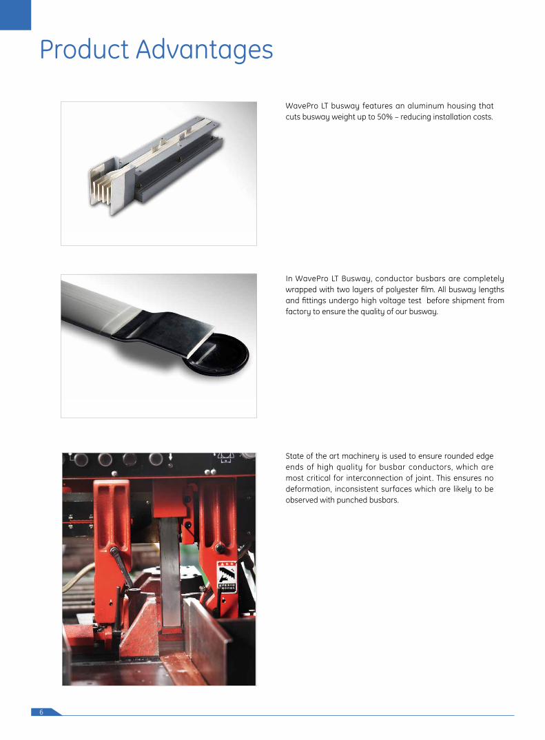
WavePro LT busway features an aluminum housing that cuts busway weight up to 50% – reducing installation costs.
In WavePro LT Busway, conductor busbars are completely wrapped with two layers of polyester film. All busway lengths and fittings undergo high voltage test before shipment from factory to ensure the quality of our busway.
State of the art machinery is used to ensure rounded edge ends of high quality for busbar conductors, which are most critical for interconnection of joint . This ensures no deformation, inconsistent surfaces which are likely to be observed with punched busbars.
7
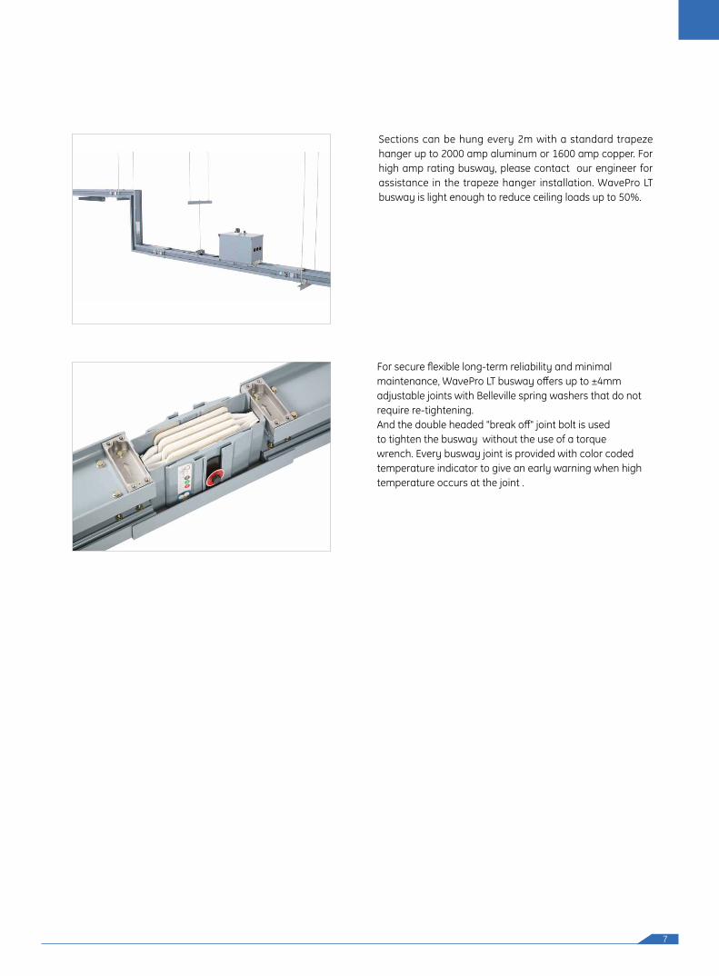
Sections can be hung every 2m with a standard trapeze hanger up to 2000 amp aluminum or 1600 amp copper. For high amp rating busway, please contact our engineer for assistance in the trapeze hanger installation. WavePro LT busway is light enough to reduce ceiling loads up to 50%.
For secure flexible long-term reliability and minimal maintenance, WavePro LT busway offers up to ±4mm adjustable joints with Belleville spring washers that do notrequire re-tightening. And the double headed "break off" joint bolt is used to tighten the busway without the use of a torque wrench. Every busway joint is provided with color coded temperature indicator to give an early warning when high temperature occurs at the joint .
8
Cable and Wire Conversion
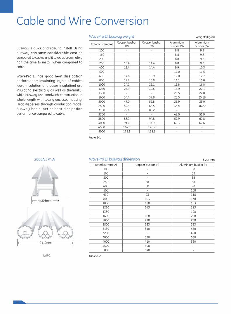
Busway is quick and easy to install. Using busway can save considerable cost as compared to cables and it takes approximately half the time to install when compared to cable.
WavePro LT has good heat dissipation performance; insulating layers of cables (core insulation and outer insulation) are insulating electrically as well as thermally, while busway use sandwich construction in whole length with totally enclosed housing. Heat disperses through conduction mode. Busway has superior heat dissipation performance compared to cable.
2000A,3P4W
Rated current (A) Copper busbar 4W
Copper busbar 5W
Aluminium busbar 4W
Aluminium busbar 5W
100 - - 8.8 9.2160 - - 8.8 9.2200 - - 8.8 9.2250 13.4 14.4 8.8 9.2400 13.4 14.4 9.9 10.3500 - - 11.0 11.5630 14.8 15.9 12.0 12.7800 17.4 18.8 14.1 15.0
1000 24.1 26.1 15.8 16.81250 27.9 30.5 18.9 20.11350 - - 20.5 22.01600 34.4 37.8 23.5 25.182000 47.0 51.8 26.9 29.02500 59.3 65.5 33.4 36.223150 72.6 80.2 - -3200 - - 48.0 51.93800 85.7 94.8 57.9 62.84000 91.0 100.6 62.3 67.64500 114.6 126.9 - -5000 125.1 138.6 - -
Rated current (A) Copper busbar (H) Aluminium busbar (H)100 - 88160 - 88200 - 88250 88 88400 88 98500 - 108630 93 118800 103 138
1000 128 1531250 143 1831350 - 1981600 168 2282000 218 2582500 263 3233150 340 4603200 - 4603800 390 5504000 410 5904500 500 -5000 540 -
Weight: (kg/m)
Size: mm
table.8-2
table.8-1
WavePro LT busway weight
WavePro LT busway dimension
fig.8-1
2000A� 3P4W a=187mmH=203mm
2110mm
9
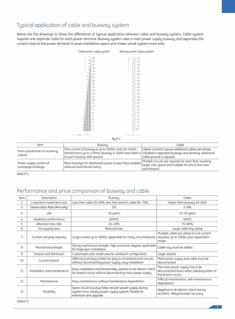
Below are the drawings to show the differences of typical application between cable and busway system. Cable system requires one separate cable for each power terminal. Busway system uses a main power supply busway and separates the current close to the power terminal. It saves installation space and makes whole system more safe.
Typical application of cable and busway system
Performance and price comparison of busway and cable
Item Busway Cable
From transformer to incoming cubicle
Max current of busway is up to 5000A, and can match transformers up to 2.5MVA. Busway is 100% load rated in its own housing, with ground.
Higher currents require additional cables per phase, installed in separate housings and derating. Additional cable ground is required.
Power supply control of multistage buildings
Riser busways for distributed power to each floor enables reduced switchboard sizing.
Multiple circuits are required for each floor resulting larger riser space and multiple MCCB's in the main switchboard.
Item Description Busway Cable1 Long-term investment cost Less than cable 50~60%, less than branch cable 60~70%. Higher than busway 50~60%2 Depreciation Rate (Annually) 2% 5~8%
3 Life 50 years 15~20 years
4 Insulation performance ≥20MΩ ≥5MΩ5 Alteration loss rate 10~20% 70~80%6 Occupying area Reduced size Large cable tray sizing
7 Current carrying capacity Large current up to 5000A, applicable for many circumstances.Multiple cables per phase to suit current required, up to 1600A, poor application range.
8 Mechanical strength Strong mechanical strength, high protection degree, applicable for large span installation. Cable tray must be added.
9 Feature and dimension Customized color, small volume, sandwich configuration. Large volume
10 Current branch Offering multi plug outlets for plug to increase branch circuits without disconnecting power supply, easy installation.
Main power supply and cable must be disconnected.
11 Installation and maintenance Easy installation and disassembly, positive to do electric check for branch circuit without disconnecting main power supply.
The main power supply has to be disconnected down when checking either of the branch circuit.
12 Maintenance Easy maintenance, without maintenance degradation. Difficult maintenance, with maintenance degradation.
13 FlexibilitySpare circuit bus plug helps recover power supply during system error, steady power supply system, flexible for extension and upgrade.
Negative to do electric check during accident, delayed power recovery.
fig.9-1
table.9-1
table.9-2
1
2
3
4
5
6
7
8
9
10
11
12
13
14
15
16
17
18
19
20
21
22
23
Busway power supply system
1
2
3
4
5
6
7
8
9
10
11
12
13
14
15
16
17
18
19
20
21
22
23
Cable power supply system

10
Electrical Characteristics
Grounding bar resistance of WavePro LT busway system (temperature=200C):
WavePro LT busway's aluminum alloy housing provide an extremely low impedance ground path with small resistance (reduced wattlosses) for both copper and aluminum systems.Plug-in outlet grounding is supplied with tin-plated copper tabs bolted to the plug in box housing for superior continuity through standard bus plug ground stabs. Optional internal ground busbar is also available to provide a complete system.
No. Rated current (A) Resistance (10-6Ω/m)1 250 207.9 2 400 207.9 3 630 179.1 4 800 141.1 5 1000 94.2 6 1250 81.0 8 1600 64.39 2000 46.7
10 2500 37.611 3150 28.9 12 3800 24.8 13 4000 23.3 14 4500 18.8 15 5000 17.4
No. Rated current (A) Resistance (10-6Ω/m)1 250 104.0 2 400 104.0 3 630 89.6 4 800 70.55 1000 47.1 6 1250 40.5 8 1600 32.19 2000 23.3
10 2500 18.811 3150 14.412 3800 12.4 13 4000 11.7 14 4500 9.4 15 5000 8.7
DC resistance copper bar (Internal 50% ground bus)
DC resistance aluminium bar (Internal 50% ground bus)
DC resistance copper bar(Internal 50% ground bus + Integraded housing ground)
DC resistance aluminium bar(Internal 50% ground bus + Integraded housing ground)
No. Rated current (A) Resistance (10-6Ω/m)1 100 342.7 2 160 342.7 3 200 342.7 4 250 342.7 5 400 259.8 6 500 210.7 7 630 178.1 8 800 138.0 9 1000 119.4
10 1250 95.211 1350 86.1 12 1600 73.413 2000 63.3 14 2500 50.415 3150 35.016 3200 35.017 3800 28.6 18 4000 25.2
No. Rated current (A) Resistance (10-6Ω/m)1 100 171.3 2 160 171.3 3 200 171.3 4 250 171.3 5 400 129.9 6 500 105.3 7 630 89.0 8 800 69.0 9 1000 59.7
10 1250 47.611 1350 43.0 12 1600 36.713 2000 31.7 14 2500 25.215 3150 17.516 3200 17.517 3800 14.3 18 4000 12.6
table.10-1
table.10-3
table.10-2
table.10-4
11
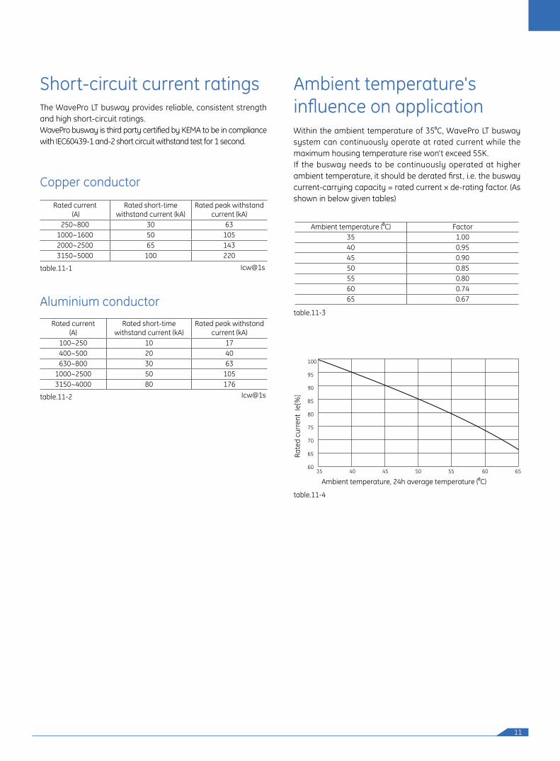
Ambient temperature's influence on applicationWithin the ambient temperature of 350C, WavePro LT busway system can continuously operate at rated current while the maximum housing temperature rise won't exceed 55K. If the busway needs to be continuously operated at higher ambient temperature, it should be derated first, i.e. the busway current-carrying capacity = rated current x de-rating factor. (As shown in below given tables)
The WavePro LT busway provides reliable, consistent strength and high short-circuit ratings.WavePro busway is third party certified by KEMA to be in compliance with IEC60439-1 and-2 short circuit withstand test for 1 second.
Ambient temperature (0C) Factor35 1.0040 0.9545 0.9050 0.8555 0.8060 0.7465 0.67
Short-circuit current ratings
Copper conductor
Aluminium conductor
Rated current (A)
Rated short-time withstand current (kA)
Rated peak withstand current (kA)
250~800 30 631000~1600 50 1052000~2500 65 1433150~5000 100 220
Rated current(A)
Rated short-time withstand current (kA)
Rated peak withstand current (kA)
100~250 10 17400~500 20 40630~800 30 63
1000~2500 50 1053150~4000 80 176
Icw@1s
Icw@1s
Ambient temperature, 24h average temperature (0C)
Rate
d cu
rren
t Ie
[%]
table.11-1
table.11-3
table.11-2
table.11-4
35 40 45 50 55 60 65
100
95
90
85
80
75
70
65
60
12
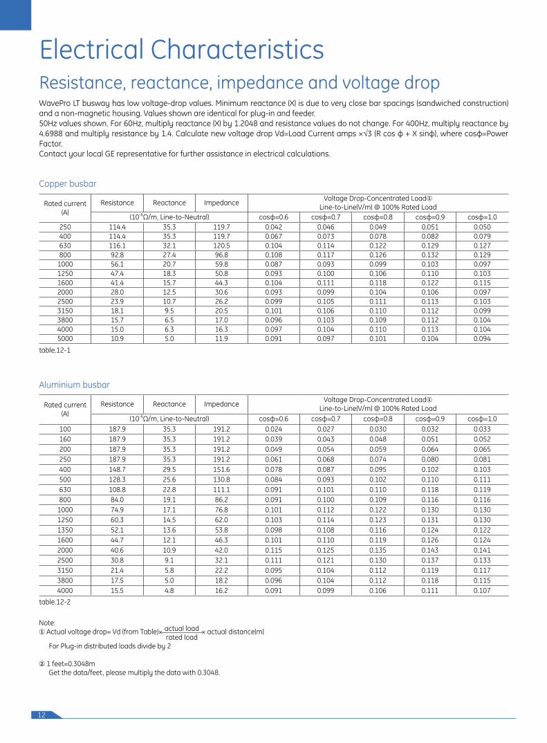
Resistance, reactance, impedance and voltage drop
Copper busbar
Aluminium busbar
Rated current(A)
Resistance Reactance Impedance Voltage Drop-Concentrated LoadLine-to-Line(V/m) @ 100% Rated Load
(10-6Ω/m, Line-to-Neutral) cosφ=0.6 cosφ=0.7 cosφ=0.8 cosφ=0.9 cosφ=1.0250 114.4 35.3 119.7 0.042 0.046 0.049 0.051 0.050 400 114.4 35.3 119.7 0.067 0.073 0.078 0.082 0.079 630 116.1 32.1 120.5 0.104 0.114 0.122 0.129 0.127 800 92.8 27.4 96.8 0.108 0.117 0.126 0.132 0.129
1000 56.1 20.7 59.8 0.087 0.093 0.099 0.103 0.097 1250 47.4 18.3 50.8 0.093 0.100 0.106 0.110 0.103 1600 41.4 15.7 44.3 0.104 0.111 0.118 0.122 0.115 2000 28.0 12.5 30.6 0.093 0.099 0.104 0.106 0.097 2500 23.9 10.7 26.2 0.099 0.105 0.111 0.113 0.103 3150 18.1 9.5 20.5 0.101 0.106 0.110 0.112 0.099 3800 15.7 6.5 17.0 0.096 0.103 0.109 0.112 0.104 4000 15.0 6.3 16.3 0.097 0.104 0.110 0.113 0.104 5000 10.9 5.0 11.9 0.091 0.097 0.101 0.104 0.094
Rated current(A)
Resistance Reactance Impedance Voltage Drop-Concentrated LoadLine-to-Line(V/m) @ 100% Rated Load
(10-6Ω/m, Line-to-Neutral) cosφ=0.6 cosφ=0.7 cosφ=0.8 cosφ=0.9 cosφ=1.0100 187.9 35.3 191.2 0.024 0.027 0.030 0.032 0.033 160 187.9 35.3 191.2 0.039 0.043 0.048 0.051 0.052 200 187.9 35.3 191.2 0.049 0.054 0.059 0.064 0.065 250 187.9 35.3 191.2 0.061 0.068 0.074 0.080 0.081 400 148.7 29.5 151.6 0.078 0.087 0.095 0.102 0.103 500 128.3 25.6 130.8 0.084 0.093 0.102 0.110 0.111 630 108.8 22.8 111.1 0.091 0.101 0.110 0.118 0.119 800 84.0 19.1 86.2 0.091 0.100 0.109 0.116 0.116
1000 74.9 17.1 76.8 0.101 0.112 0.122 0.130 0.130 1250 60.3 14.5 62.0 0.103 0.114 0.123 0.131 0.130 1350 52.1 13.6 53.8 0.098 0.108 0.116 0.124 0.122 1600 44.7 12.1 46.3 0.101 0.110 0.119 0.126 0.124 2000 40.6 10.9 42.0 0.115 0.125 0.135 0.143 0.141 2500 30.8 9.1 32.1 0.111 0.121 0.130 0.137 0.133 3150 21.4 5.8 22.2 0.095 0.104 0.112 0.119 0.117 3800 17.5 5.0 18.2 0.096 0.104 0.112 0.118 0.115 4000 15.5 4.8 16.2 0.091 0.099 0.106 0.111 0.107
Note: Actual voltage drop= Vd (from Table)× × actual distance(m) For Plug-in distributed loads divide by 2
1 feet=0.3048m Get the data/feet, please multiply the data with 0.3048.
actual loadrated load
WavePro LT busway has low voltage-drop values. Minimum reactance (X) is due to very close bar spacings (sandwiched construction) and a non-magnetic housing. Values shown are identical for plug-in and feeder.50Hz values shown. For 60Hz, multiply reactance (X) by 1.2048 and resistance values do not change. For 400Hz, multiply reactance by 4.6988 and multiply resistance by 1.4. Calculate new voltage drop Vd=Load Current amps ×√3 (R cos ф + X sinф), where cosф=Power Factor.Contact your local GE representative for further assistance in electrical calculations.
Electrical Characteristics
table.12-1
table.12-2
13
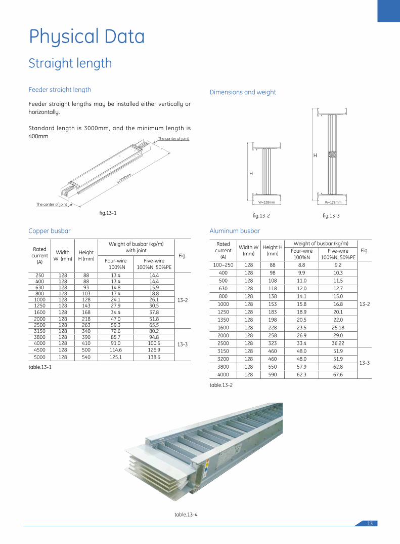
Straight length
Physical Data
Feeder straight length Dimensions and weight
Aluminum busbar
Feeder straight lengths may be installed either vertically or horizontally.
Standard length is 3000mm, and the minimum length is 400mm.
Rated current
(A)
Width W (mm)
Height H (mm)
Weight of busbar (kg/m) with joint
Fig.Four-wire 100%N
Five-wire100%N, 50%PE
250 128 88 13.4 14.4
13-2
400 128 88 13.4 14.4 630 128 93 14.8 15.9 800 128 103 17.4 18.8
1000 128 128 24.1 26.1 1250 128 143 27.9 30.5 1600 128 168 34.4 37.8 2000 128 218 47.0 51.82500 128 263 59.3 65.53150 128 340 72.6 80.2
13-33800 128 390 85.7 94.8 4000 128 410 91.0 100.6 4500 128 500 114.6 126.9 5000 128 540 125.1 138.6
Copper busbar
fig.13-1 fig.13-3fig.13-2
table.13-1
table.13-2
table.13-4
H
W=128mm
H
W=128mm
Rated current
(A)
Width W (mm)
Height H (mm)
Weight of busbar (kg/m)Fig.Four-wire
100%NFive-wire
100%N, 50%PE100~250 128 88 8.8 9.2
13-2
400 128 98 9.9 10.3 500 128 108 11.0 11.5 630 128 118 12.0 12.7 800 128 138 14.1 15.0
1000 128 153 15.8 16.8 1250 128 183 18.9 20.1 1350 128 198 20.5 22.0 1600 128 228 23.5 25.182000 128 258 26.9 29.0 2500 128 323 33.4 36.223150 128 460 48.0 51.9
13-33200 128 460 48.0 51.9 3800 128 550 57.9 62.8 4000 128 590 62.3 67.6
L
The center of joint
The center of joint
L=3000mm
14
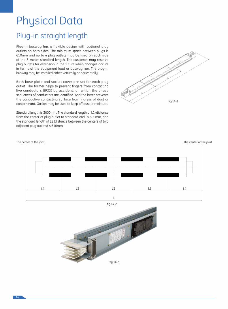
Plug-in straight lengthPlug-in busway has a flexible design with optional plug outlets on both sides. The minimum space between plugs is 610mm and up to 4 plug outlets may be fixed on each side of the 3-meter standard length. The customer may reserve plug outlets for extension in the future when changes occurs in terms of the equipment load or busway run. The plug-in busway may be installed either vertically or horizontally.
Both base plate and socket cover are set for each plug outlet . The former helps to prevent fingers from contacting live conductors (IP2X) by accident , on which the phase sequences of conductors are identified. And the latter prevents the conductive contacting surface from ingress of dust or contaminant. Gasket may be used to keep off dust or moisture.
Standard length is 3000mm. The standard length of L1 (distance from the center of plug outlet to standard end) is 600mm, and the standard length of L2 (distance between the centers of two adjacent plug outlets) is 610mm.
L1
L
L2
fig.14-1
fig.14-2
fig.14-3
L1L2L1 L2 L2
L
The center of the joint The center of the joint
Physical Data
15
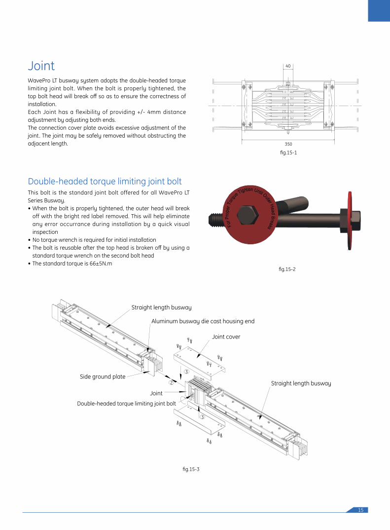
Joint
Double-headed torque limiting joint bolt
WavePro LT busway system adopts the double-headed torque limiting joint bolt . When the bolt is properly tightened, the top bolt head will break off so as to ensure the correctness of installation.Each Joint has a flexibility of providing +/- 4mm distance adjustment by adjusting both ends.The connection cover plate avoids excessive adjustment of the joint. The joint may be safely removed without obstructing the adjacent length.
This bolt is the standard joint bolt offered for all WavePro LT Series Busway.• When the bolt is properly tightened, the outer head will break
off with the bright red label removed. This will help eliminate any error occurrance during installation by a quick visual inspection
• No torque wrench is required for initial installation• The bolt is reusable after the top head is broken off by using a
standard torque wrench on the second bolt head• The standard torque is 66±5N.m
40
350
fig.15-1
fig.15-2
fig.15-3
Side ground plate
Straight length busway
Aluminum busway die cast housing end
Joint cover
Straight length busway
Joint
2
3
3
Double-headed torque limiting joint bolt
16
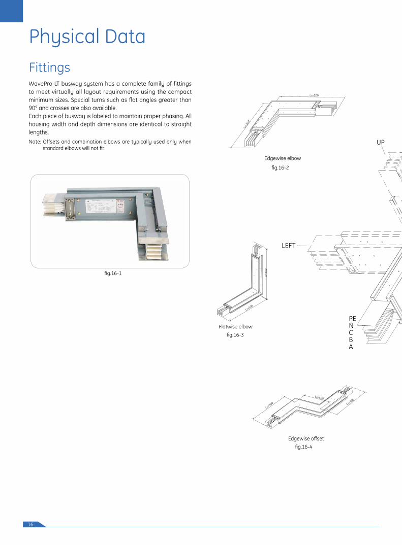
FittingsWavePro LT busway system has a complete family of fittings to meet virtually all layout requirements using the compact minimum sizes. Special turns such as flat angles greater than 90° and crosses are also available.Each piece of busway is labeled to maintain proper phasing. All housing width and depth dimensions are identical to straight lengths. Note: Offsets and combination elbows are typically used only when
standard elbows will not fit.
Physical Data
L1=50
0
L2=500
Edgewise elbow
Flatwise elbow
L1=500
L2=5
00
Edgewise offset
L1=500
L2=500
L3=500
fig.16-1
fig.16-3
fig.16-4
fig.16-2
LEFT
PENCBA
UP
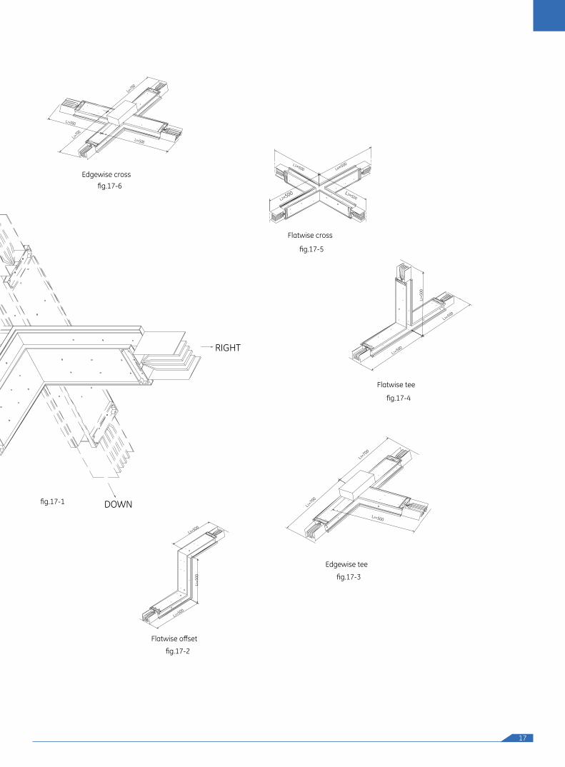
17
DOWN
RIGHT
Flatwise offset
L1=500
L2=5
00
L3=500
Edgewise tee
L2=500
L1=700
L3=700
Flatwise tee
L1=500
L3=500
L2=5
00
Edgewise cross
L1=500
L4=700
L2=700
L3=500
Flatwise cross
L1=500
L3=500
L4=500
L2=500
fig.17-1
fig.17-2
fig.17-3
fig.17-4
fig.17-5
fig.17-6

18
Physical Data
Edgewise elbowfig.18-1
Edgewise elbow
Fittings data
table.18-1
L1=50
0
L2=500
Rated current
(A)
Copper busway size (mm) Aluminium busway size (mm)
Busway height H
Minimum Standard Busway height H
Minimum Standard
L1 L2 L1 L2 L1 L2 L1 L2100 - - - - - 88 245 245 500 500160 - - - - - 88 245 245 500 500200 - - - - - 88 245 245 500 500250 88 245 245 500 500 88 245 245 500 500400 88 245 245 500 500 98 245 245 500 500500 - - - - - 108 245 245 500 500630 93 245 245 500 500 118 245 245 500 500800 103 245 245 500 500 138 245 245 500 500
1000 128 245 245 500 500 153 245 245 500 5001250 143 245 245 500 500 183 245 245 500 5001350 - - - - - 198 245 245 500 5001600 168 245 245 500 500 228 245 245 500 5002000 218 245 245 500 500 258 245 245 500 5002500 263 245 245 500 500 323 245 245 500 5003150 340 245 245 500 500 460 245 245 500 5003200 - - - - - 460 245 245 500 5003800 390 245 245 500 500 550 245 245 500 5004000 410 245 245 500 500 590 245 245 500 5004500 500 245 245 500 500 - - - - -5000 540 245 245 500 500 - - - - -
Flatwise elbowfig.18-2
Flatwise elbow
table.18-2
L 2=5
00
L1=500
Rated current
(A)
Copper busway size (mm) Aluminium busway size (mm)
Busway height H
Minimum Standard Busway height H
Minimum Standard
L1 L2 L1 L2 L1 L2 L1 L2100 - - - - - 88 224 224 500 500160 - - - - - 88 224 224 500 500200 - - - - - 88 224 224 500 500250 88 224 224 500 500 88 224 224 500 500400 88 224 224 500 500 98 229 229 500 500500 - - - - - 108 234 234 500 500630 93 227 227 500 500 118 239 239 500 500800 103 232 232 500 500 138 249 249 500 500
1000 128 244 244 500 500 153 257 257 500 5001250 143 252 252 500 500 183 272 272 500 5001350 - - - - - 198 279 279 500 5001600 168 264 264 500 500 228 294 294 500 5002000 218 289 289 500 500 258 309 309 500 5002500 263 312 312 500 500 323 342 342 500 5003150 340 350 350 500 500 460 410 410 500 5003200 - - - - - 460 410 410 500 5003800 390 375 375 500 500 550 455 455 500 5004000 410 385 385 500 500 590 475 475 500 5004500 500 430 430 500 500 - - - - -5000 540 450 450 500 500 - - - - -
19
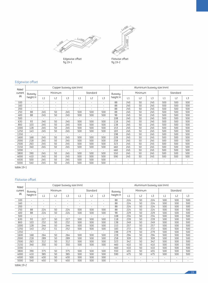
Edgewise offsetfig.19-1
L1=500L2=500
L3=500
Edgewise offset
table.19-1
Rated current
(A)
Copper busway size (mm) Aluminium busway size (mm)
Busway height H
Minimum Standard Busway height H
Minimum Standard
L1 L2 L3 L1 L2 L3 L1 L2 L3 L1 L2 L3100 - - - - - - - 88 245 50 245 500 500 500160 - - - - - - - 88 245 50 245 500 500 500200 - - - - - - - 88 245 50 245 500 500 500250 88 245 50 245 500 500 500 88 245 50 245 500 500 500400 88 245 50 245 500 500 500 98 245 50 245 500 500 500500 - - - - - - - 108 245 50 245 500 500 500630 93 245 50 245 500 500 500 118 245 50 245 500 500 500800 103 245 50 245 500 500 500 138 245 50 245 500 500 500
1000 128 245 50 245 500 500 500 153 245 50 245 500 500 5001250 143 245 50 245 500 500 500 183 245 50 245 500 500 5001350 - - - - - - - 198 245 50 245 500 500 5001600 168 245 50 245 500 500 500 228 245 50 245 500 500 5002000 218 245 50 245 500 500 500 258 245 50 245 500 500 5002500 263 245 50 245 500 500 500 323 245 50 245 500 500 5003150 340 245 50 245 500 500 500 460 245 50 245 500 500 5003200 - - - - - - - 460 245 50 245 500 500 5003800 390 245 50 245 500 500 500 550 245 50 245 500 500 5004000 410 245 50 245 500 500 500 590 245 50 245 500 500 5004500 500 245 50 245 500 500 500 - - - - - - -5000 540 245 50 245 500 500 500 - - - - - - -
Flatwise offset
Flatwise offsetfig.19-2
L1=500
L2=5
00
L3=500
table.19-2
Rated current
(A)
Copper busway size (mm) Aluminium busway size (mm)
Busway height H
Minimum Standard Busway height H
Minimum Standard
L1 L2 L3 L1 L2 L3 L1 L2 L3 L1 L2 L3100 - - - - - - - 88 224 50 224 500 500 500160 - - - - - - - 88 224 50 224 500 500 500200 - - - - - - - 88 224 50 224 500 500 500250 88 224 50 224 500 500 500 88 224 50 224 500 500 500400 88 224 50 224 500 500 500 98 229 50 229 500 500 500500 - - - - - - - 108 234 50 234 500 500 500630 93 227 50 227 500 500 500 118 239 50 239 500 500 500800 103 232 50 232 500 500 500 138 249 50 249 500 500 500
1000 128 244 50 244 500 500 500 153 257 50 257 500 500 5001250 143 252 51 252 500 500 500 183 272 50 272 500 500 5001350 - - - - - - - 198 279 50 279 500 500 5001600 168 264 50 264 500 500 500 228 294 50 294 500 500 5002000 218 289 50 289 500 500 500 258 309 50 309 500 500 5002500 263 312 50 312 500 500 500 323 342 50 342 500 500 5003150 340 350 50 350 500 500 500 460 410 50 410 500 500 5003200 - - - - - - - 460 410 50 410 500 500 5003800 390 375 50 375 500 500 500 550 455 50 455 500 500 5004000 410 385 50 385 500 500 500 590 475 50 475 500 500 5004500 500 430 50 430 500 500 500 - - - - - - -5000 540 450 50 450 500 500 500 - - - - - - -
20
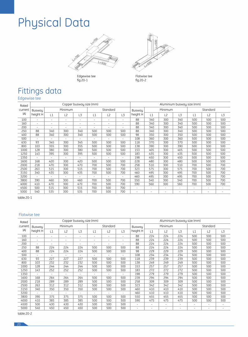
Edgewise teefig.20-1
L1=700
L3=700
L2=500
Physical Data
Edgewise teeFittings data
table.20-1
Rated current
(A)
Copper busway size (mm) Aluminium busway size (mm)
Busway height H
Minimum Standard Busway height H
Minimum Standard
L1 L2 L3 L1 L2 L3 L1 L2 L3 L1 L2 L3100 - - - - - - - 88 340 300 340 500 500 500160 - - - - - - - 88 340 300 340 500 500 500200 - - - - - - - 88 340 300 340 500 500 500250 88 340 300 340 500 500 500 88 340 300 340 500 500 500400 88 340 300 340 500 500 500 98 350 300 350 500 500 500500 - - - - - - - 108 360 300 360 500 500 500630 93 345 300 345 500 500 500 118 370 300 370 500 500 500800 103 355 300 355 500 500 500 138 390 300 390 500 500 500
1000 128 380 300 380 500 500 500 153 405 300 405 500 500 5001250 143 395 300 395 500 500 500 183 435 300 435 500 500 5001350 - - - - - - - 198 450 300 450 500 500 5001600 168 420 300 420 500 500 500 228 480 300 480 500 500 5002000 218 470 300 470 700 500 700 258 510 300 510 700 500 7002500 263 515 300 515 700 500 700 323 575 300 575 700 500 7003150 340 435 300 435 700 500 700 460 495 300 495 700 500 7003200 - - - - - - - 460 495 300 495 700 500 7003800 390 460 300 460 700 500 700 550 540 300 540 700 500 7004000 410 470 300 470 700 500 700 590 560 300 560 700 500 7004500 500 515 300 515 700 500 700 - - - - - - -5000 540 535 300 535 700 500 700 - - - - - - -
Flatwise teefig.20-2
L1=500
L3=500
L2=5
00
Flatwise tee
table.20-2
Rated current
(A)
Copper busway size (mm) Aluminium busway size (mm)
Busway height H
Minimum Standard Busway height H
Minimum Standard
L1 L2 L3 L1 L2 L3 L1 L2 L3 L1 L2 L3100 - - - - - - - 88 224 224 224 500 500 500160 - - - - - - - 88 224 224 224 500 500 500200 - - - - - - - 88 224 224 224 500 500 500250 88 224 224 224 500 500 500 88 224 224 224 500 500 500400 88 224 224 224 500 500 500 98 229 229 229 500 500 500500 - - - - - - - 108 234 234 234 500 500 500630 93 227 227 227 500 500 500 118 239 239 239 500 500 500800 103 232 232 232 500 500 500 138 249 249 249 500 500 500
1000 128 244 244 244 500 500 500 153 257 257 257 500 500 5001250 143 252 252 252 500 500 500 183 272 272 272 500 500 5001350 - - - - - - - 198 279 279 279 500 500 5001600 168 264 264 264 500 500 500 228 294 294 294 500 500 5002000 218 289 289 289 500 500 500 258 309 309 309 500 500 5002500 263 312 312 312 500 500 500 323 342 342 342 500 500 5003150 340 350 350 350 500 500 500 460 410 410 410 500 500 5003200 - - - - - - - 460 410 410 410 500 500 5003800 390 375 375 375 500 500 500 550 455 455 455 500 500 5004000 410 385 385 385 500 500 500 590 475 475 475 500 500 5004500 500 430 430 430 500 500 500 - - - - - - -5000 540 450 450 450 500 500 500 - - - - - - -
21
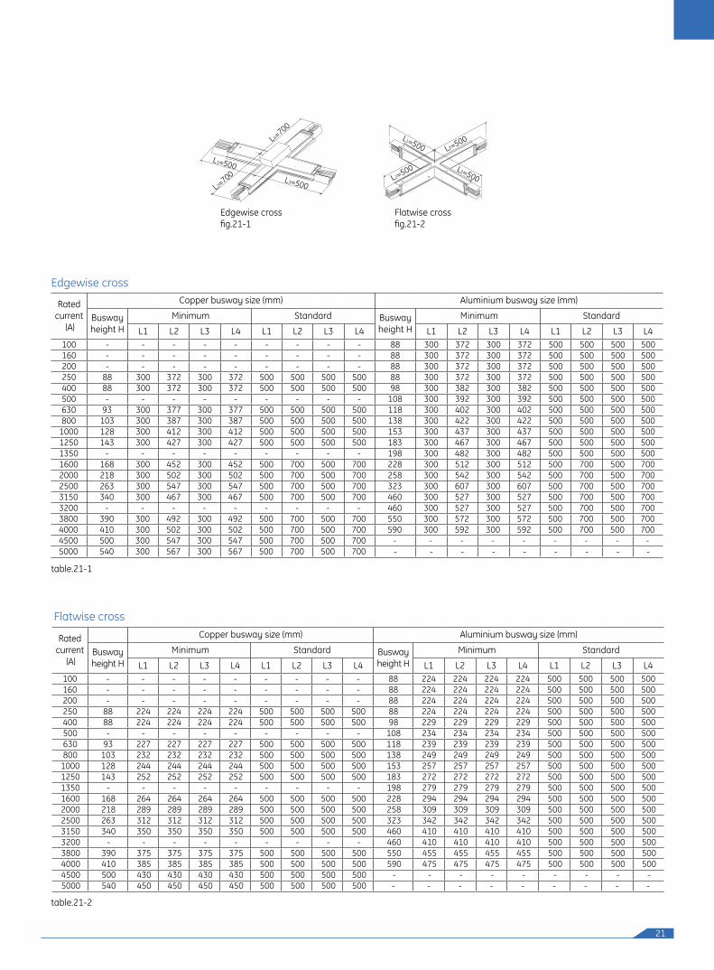
Edgewise crossfig.21-1
L3=500
L1=500
L2=700
L4=700
Edgewise cross
table.21-1
Rated current
(A)
Copper busway size (mm) Aluminium busway size (mm)
Busway height H
Minimum Standard Busway height H
Minimum Standard
L1 L2 L3 L4 L1 L2 L3 L4 L1 L2 L3 L4 L1 L2 L3 L4100 - - - - - - - - - 88 300 372 300 372 500 500 500 500160 - - - - - - - - - 88 300 372 300 372 500 500 500 500200 - - - - - - - - - 88 300 372 300 372 500 500 500 500250 88 300 372 300 372 500 500 500 500 88 300 372 300 372 500 500 500 500400 88 300 372 300 372 500 500 500 500 98 300 382 300 382 500 500 500 500500 - - - - - - - - - 108 300 392 300 392 500 500 500 500630 93 300 377 300 377 500 500 500 500 118 300 402 300 402 500 500 500 500800 103 300 387 300 387 500 500 500 500 138 300 422 300 422 500 500 500 500
1000 128 300 412 300 412 500 500 500 500 153 300 437 300 437 500 500 500 5001250 143 300 427 300 427 500 500 500 500 183 300 467 300 467 500 500 500 5001350 - - - - - - - - - 198 300 482 300 482 500 500 500 5001600 168 300 452 300 452 500 700 500 700 228 300 512 300 512 500 700 500 7002000 218 300 502 300 502 500 700 500 700 258 300 542 300 542 500 700 500 7002500 263 300 547 300 547 500 700 500 700 323 300 607 300 607 500 700 500 7003150 340 300 467 300 467 500 700 500 700 460 300 527 300 527 500 700 500 7003200 - - - - - - - - - 460 300 527 300 527 500 700 500 7003800 390 300 492 300 492 500 700 500 700 550 300 572 300 572 500 700 500 7004000 410 300 502 300 502 500 700 500 700 590 300 592 300 592 500 700 500 7004500 500 300 547 300 547 500 700 500 700 - - - - - - - - -5000 540 300 567 300 567 500 700 500 700 - - - - - - - - -
Flatwise cross
Flatwise crossfig.21-2
L3=500
L1=500
L2=500
L2=500
table.21-2
Rated current
(A)
Copper busway size (mm) Aluminium busway size (mm)
Busway height H
Minimum Standard Busway height H
Minimum Standard
L1 L2 L3 L4 L1 L2 L3 L4 L1 L2 L3 L4 L1 L2 L3 L4100 - - - - - - - - - 88 224 224 224 224 500 500 500 500160 - - - - - - - - - 88 224 224 224 224 500 500 500 500200 - - - - - - - - - 88 224 224 224 224 500 500 500 500250 88 224 224 224 224 500 500 500 500 88 224 224 224 224 500 500 500 500400 88 224 224 224 224 500 500 500 500 98 229 229 229 229 500 500 500 500500 - - - - - - - - - 108 234 234 234 234 500 500 500 500630 93 227 227 227 227 500 500 500 500 118 239 239 239 239 500 500 500 500800 103 232 232 232 232 500 500 500 500 138 249 249 249 249 500 500 500 500
1000 128 244 244 244 244 500 500 500 500 153 257 257 257 257 500 500 500 5001250 143 252 252 252 252 500 500 500 500 183 272 272 272 272 500 500 500 5001350 - - - - - - - - - 198 279 279 279 279 500 500 500 5001600 168 264 264 264 264 500 500 500 500 228 294 294 294 294 500 500 500 5002000 218 289 289 289 289 500 500 500 500 258 309 309 309 309 500 500 500 5002500 263 312 312 312 312 500 500 500 500 323 342 342 342 342 500 500 500 5003150 340 350 350 350 350 500 500 500 500 460 410 410 410 410 500 500 500 5003200 - - - - - - - - - 460 410 410 410 410 500 500 500 5003800 390 375 375 375 375 500 500 500 500 550 455 455 455 455 500 500 500 5004000 410 385 385 385 385 500 500 500 500 590 475 475 475 475 500 500 500 5004500 500 430 430 430 430 500 500 500 500 - - - - - - - - -5000 540 450 450 450 450 500 500 500 500 - - - - - - - - -
22
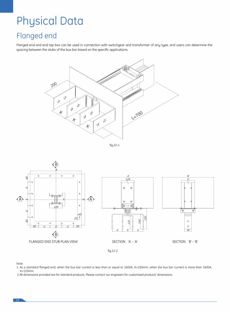
Physical DataFlanged endFlanged end and end tap box can be used in connection with switchgear and transformer of any type, and users can determine the spacing between the stubs of the bus bar based on the specific applications.
Note: 1. As a standard flanged end, when the bus bar current is less than or equal to 1600A, K=100mm; when the bus bar current is more than 1600A,
K=120mm. 2.All dimensions provided are for standard products. Please contact our engineers for customized products' dimensions.
fig.22-1
fig.22-2
FLANGED END STUB PLAN VIEW
B
A
B
SECTION `A' - 'A'
A
80
128
200
140
125
80WKKK
H
H
a a a
128
A
bb
b80
80
4020
B
A B
SECTION `B' - 'B'
200
K
KK
L=700
23
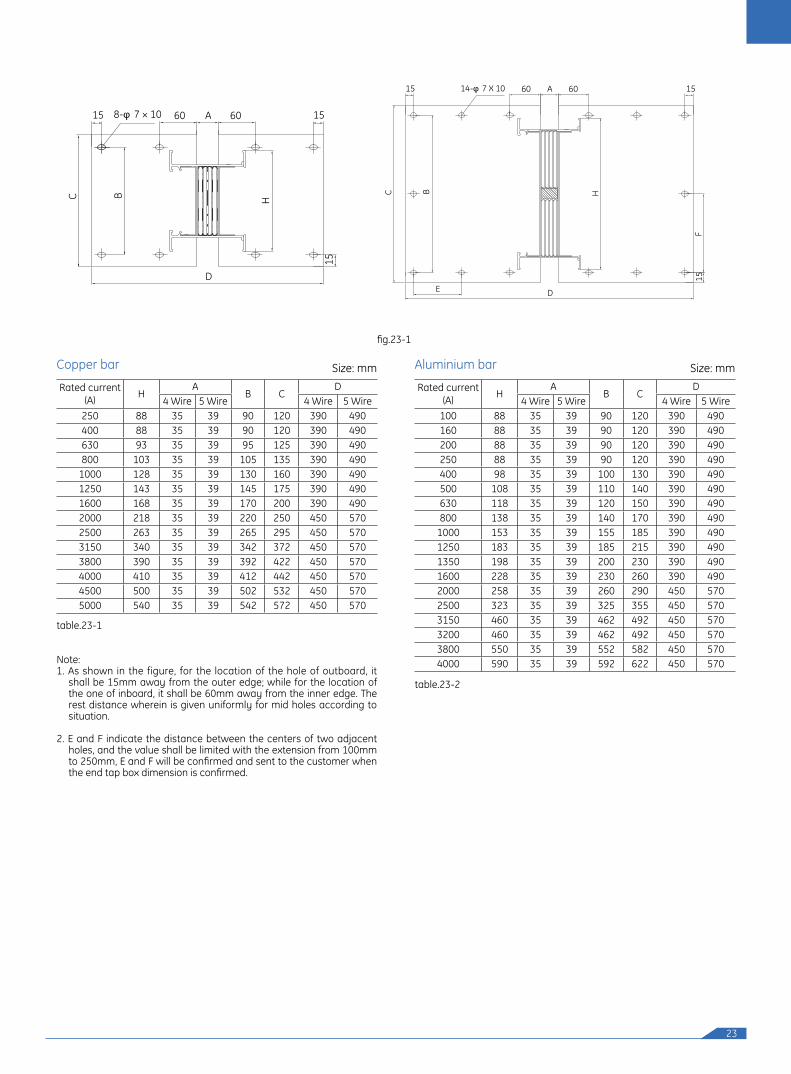
Note:1. As shown in the figure, for the location of the hole of outboard, it
shall be 15mm away from the outer edge; while for the location of the one of inboard, it shall be 60mm away from the inner edge. The rest distance wherein is given uniformly for mid holes according to situation.
2. E and F indicate the distance between the centers of two adjacent holes, and the value shall be limited with the extension from 100mm to 250mm, E and F will be confirmed and sent to the customer when the end tap box dimension is confirmed.
fig.23-1
Rated current (A) H
AB C
D4 Wire 5 Wire 4 Wire 5 Wire
100 88 35 39 90 120 390 490160 88 35 39 90 120 390 490200 88 35 39 90 120 390 490250 88 35 39 90 120 390 490400 98 35 39 100 130 390 490500 108 35 39 110 140 390 490630 118 35 39 120 150 390 490800 138 35 39 140 170 390 490
1000 153 35 39 155 185 390 4901250 183 35 39 185 215 390 4901350 198 35 39 200 230 390 4901600 228 35 39 230 260 390 4902000 258 35 39 260 290 450 5702500 323 35 39 325 355 450 5703150 460 35 39 462 492 450 5703200 460 35 39 462 492 450 5703800 550 35 39 552 582 450 5704000 590 35 39 592 622 450 570
Rated current (A) H
AB C
D4 Wire 5 Wire 4 Wire 5 Wire
250 88 35 39 90 120 390 490400 88 35 39 90 120 390 490630 93 35 39 95 125 390 490800 103 35 39 105 135 390 490
1000 128 35 39 130 160 390 4901250 143 35 39 145 175 390 4901600 168 35 39 170 200 390 4902000 218 35 39 220 250 450 5702500 263 35 39 265 295 450 5703150 340 35 39 342 372 450 5703800 390 35 39 392 422 450 5704000 410 35 39 412 442 450 5704500 500 35 39 502 532 450 5705000 540 35 39 542 572 450 570
Aluminium barCopper bar Size: mm Size: mm
table.23-1
table.23-2
HBC
60 A14-φ 7 X 10¹⁵ 60
D
15
15
E
F
60 ABC
15 60 15
HD
15
8-φ 7 × 10
24
Rated current (A) A B C K 2-M Type100 - - - - - -160 - - - - - -200 - - - - - -250 20 40 - 100 2-φ11 A400 20 40 - 100 2-φ11 A630 20 40 - 100 2-φ11 A800 20 40 - 100 2-φ11 A
1000 25 50 - 100 2-φ14 A1250 20 40 40 100 4-φ14 B1600 25 50 50 100 4-φ18 B2000 30 60 60 120 4-φ18 B2500 30 60 60 120 6-φ18 C3150 30 60 60 120 4-φ18 B3800 25 50 50 120 6-φ18 C4000 25 50 50 120 6-φ18 C4500 30 60 60 120 6-φ18 C5000 30 60 60 120 6-φ18 C
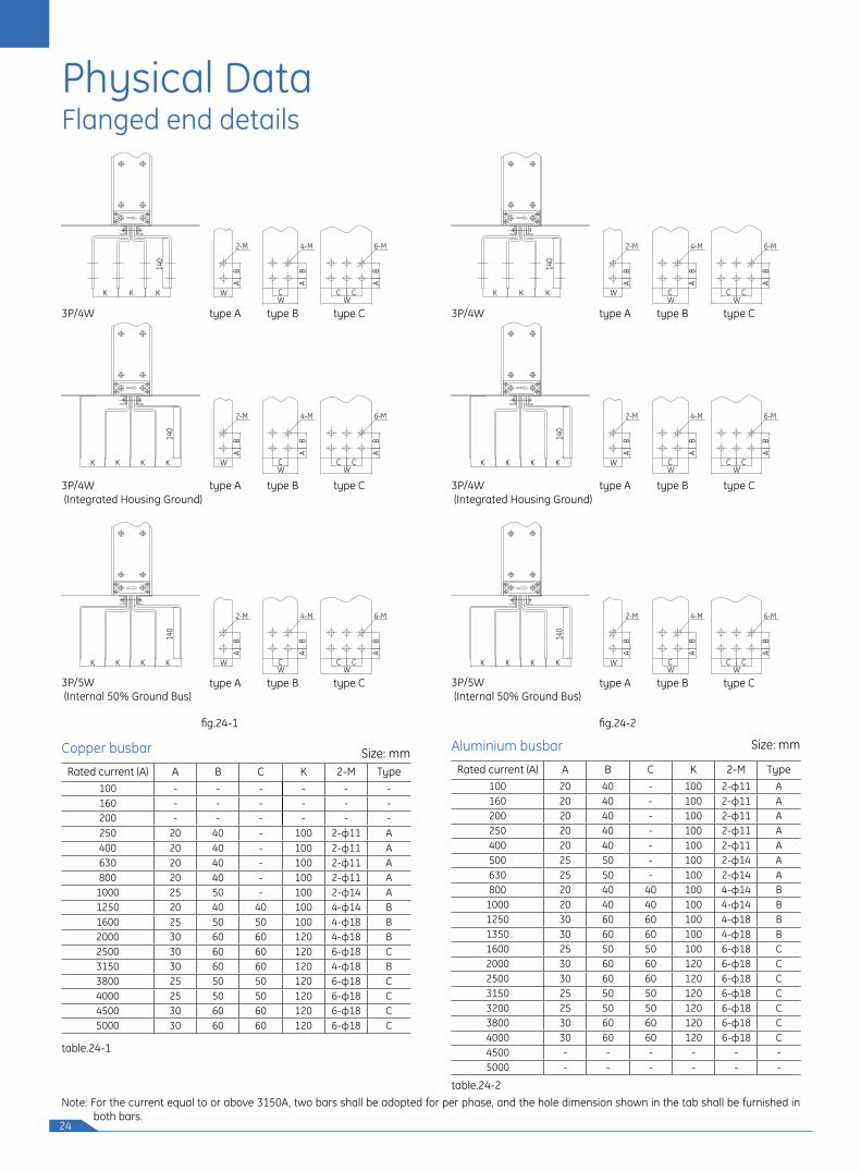
Flanged end details
fig.24-1 fig.24-2
Physical Data
Copper busbar
Note: For the current equal to or above 3150A, two bars shall be adopted for per phase, and the hole dimension shown in the tab shall be furnished in both bars.
Size: mm
table.24-1
Aluminium busbar Size: mm
table.24-2
W
AB
2-M
WK K K K
W
AB
4-M
C C C
W
AB
2-M
K K K KW W
AB
4-M
C C C
6-M
6-M
W
AB
2-M
K KKW W
AB
4-M
C C C
6-M
AB
AB
AB
140
140
140
3P/4W (Integrated Housing Ground)
type Btype A type C
W
AB
2-M
WK K K K
W
AB
4-M
C C C
W
AB
2-M
K K K KW W
AB
4-M
C C C
6-M
6-M
W
AB
2-M
K KKW W
AB
4-M
C C C
6-M
AB
AB
AB
140
140
140
type Btype A type C3P/5W (Internal 50% Ground Bus)
W
AB
2-M
WK K K K
W
AB
4-M
C C C
W
AB
2-M
K K K KW W
AB
4-M
C C C
6-M
6-M
W
AB
2-M
K KKW W
AB
4-M
C C C
6-M
AB
AB
AB
140
140
140
type A type B type C3P/4W
W
AB
2-M
WK K K K
W
AB
4-M
C C C
W
AB
2-M
K K K KW W
AB
4-M
C C C
6-M
6-M
W
AB
2-M
K KKW W
AB
4-M
C C C
6-M
AB
AB
AB
140
140
140
3P/4W (Integrated Housing Ground)
type Btype A type C
W
AB
2-M
WK K K K
W
AB
4-M
C C C
W
AB
2-M
K K K KW W
AB
4-M
C C C
6-M
6-M
W
AB
2-M
K KKW W
AB
4-M
C C C
6-M
AB
AB
AB
140
140
140
type Btype A type C3P/5W (Internal 50% Ground Bus)
W
AB
2-M
WK K K K
W
AB
4-M
C C C
W
AB
2-M
K K K KW W
AB
4-M
C C C
6-M
6-M
W
AB
2-M
K KKW W
AB
4-M
C C C
6-M
AB
AB
AB
140
140
140
type A type B type C3P/4W
Rated current (A) A B C K 2-M Type100 20 40 - 100 2-φ11 A160 20 40 - 100 2-φ11 A200 20 40 - 100 2-φ11 A250 20 40 - 100 2-φ11 A400 20 40 - 100 2-φ11 A500 25 50 - 100 2-φ14 A630 25 50 - 100 2-φ14 A800 20 40 40 100 4-φ14 B
1000 20 40 40 100 4-φ14 B1250 30 60 60 100 4-φ18 B1350 30 60 60 100 4-φ18 B1600 25 50 50 100 6-φ18 C2000 30 60 60 120 6-φ18 C2500 30 60 60 120 6-φ18 C3150 25 50 50 120 6-φ18 C3200 25 50 50 120 6-φ18 C3800 30 60 60 120 6-φ18 C4000 30 60 60 120 6-φ18 C4500 - - - - - -5000 - - - - - -
25
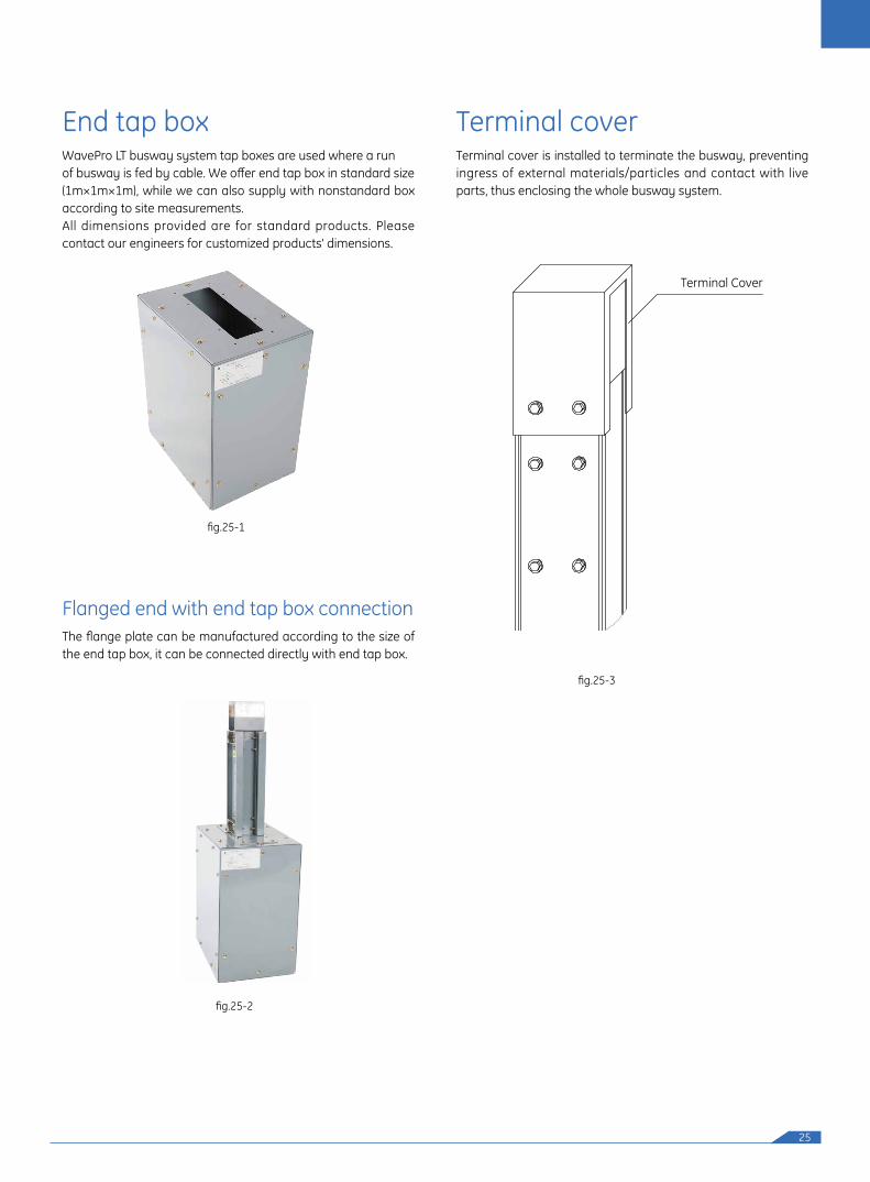
End tap box
Flanged end with end tap box connection
Terminal coverWavePro LT busway system tap boxes are used where a runof busway is fed by cable. We offer end tap box in standard size(1m×1m×1m), while we can also supply with nonstandard box according to site measurements.All dimensions provided are for standard products. Please contact our engineers for customized products' dimensions.
The flange plate can be manufactured according to the size of the end tap box, it can be connected directly with end tap box.
Terminal cover is installed to terminate the busway, preventing ingress of external materials/particles and contact with live parts, thus enclosing the whole busway system.
fig.25-3
fig.25-1
fig.25-2
Terminal Cover
26
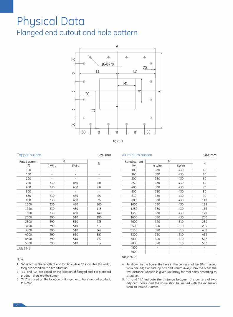
Flanged end cutout and hole pattern
fig.26-1
Rated current(A)
MN
4 Wire 5Wire100 330 430 60160 330 430 60200 330 430 60250 330 430 60400 330 430 70500 330 430 80630 330 430 90800 330 430 110
1000 330 430 1251250 330 430 1551350 330 430 1701600 330 430 2002000 390 510 2302500 390 510 2953150 390 510 4323200 390 510 4323800 390 510 5224000 390 510 5624500 - - -5000 - - -
Rated current(A)
MN
4 Wire 5Wire100 - - -160 - - -200 - - -250 330 430 60400 330 430 60500 - - -630 330 430 65800 330 430 75
1000 330 430 1001250 330 430 1151600 330 430 1402000 390 510 1902500 390 510 2353150 390 510 3123800 390 510 3624000 390 510 3824500 390 510 4725000 390 510 512
1 "A" indicates the length of end tap box while "B" indicates the width,
they are based on the site situation. 2 "L1" and "L2" are based on the location of flanged end. For standard
product, they' are the same.3 "M1" is based on the location of flanged end. For standard product,
M1=M/2.
4 As shown in the figure, the hole in the corner shall be 80mm away from one edge of end tap box and 20mm away from the other, the rest distance wherein is given uniformly for mid holes according to situation.
5 "a" and " b" indicate the distance between the centers of two adjacent holes, and the value shall be limited with the extension from 100mm to 250mm.
Size: mmSize: mm Aluminium busbarCopper busbar
table.26-1
table.26-2Note:
B
8080
b
80 a 80
N
L1
16-Ø7*9
M1
a a
bb
M
L1 L2
A
20
20
Physical Data
27
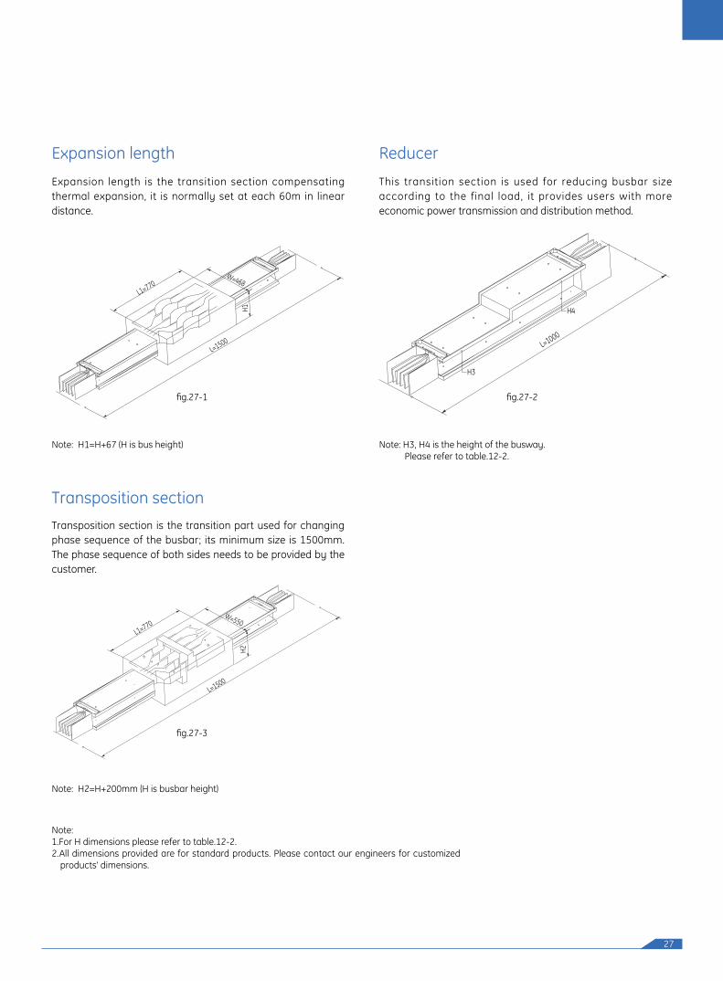
Expansion length Reducer
Transposition section
Expansion length is the transition section compensating thermal expansion, it is normally set at each 60m in linear distance.
This transition section is used for reducing busbar size according to the final load, it provides users with more economic power transmission and distribution method.
Note: H1=H+67 (H is bus height) Note: H3, H4 is the height of the busway. Please refer to table.12-2.
Note: H2=H+200mm (H is busbar height)
Note: 1.For H dimensions please refer to table.12-2.2.All dimensions provided are for standard products. Please contact our engineers for customized
products' dimensions.
Transposition section is the transition part used for changing phase sequence of the busbar; its minimum size is 1500mm. The phase sequence of both sides needs to be provided by the customer.
L=1500
L1=770W=468
H1
L=1500
PEA
BC
N
N
CB
APE
L1=770W=550
H2
L=1000
H3
H4
fig.27-1
fig.27-3
fig.27-2
28
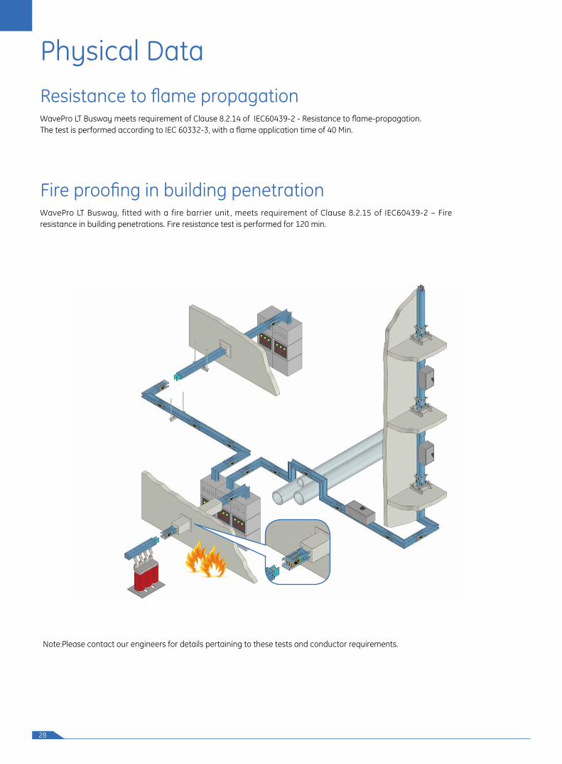
Resistance to flame propagation
Fire proofing in building penetration
Physical Data
WavePro LT Busway meets requirement of Clause 8.2.14 of IEC60439-2 - Resistance to flame-propagation. The test is performed according to IEC 60332-3, with a flame application time of 40 Min.
WavePro LT Busway, fitted with a fire barrier unit , meets requirement of Clause 8.2.15 of IEC60439-2 – Fire resistance in building penetrations. Fire resistance test is performed for 120 min.
Note:Please contact our engineers for details pertaining to these tests and conductor requirements.
29
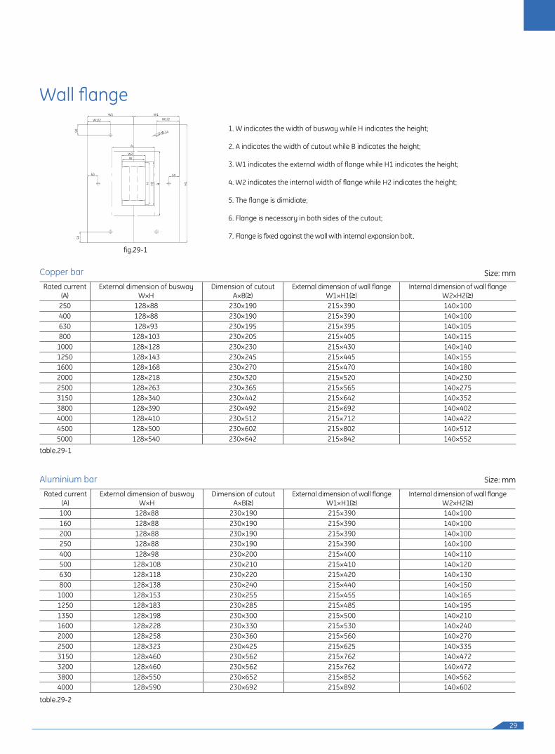
Wall flange
1. W indicates the width of busway while H indicates the height;
2. A indicates the width of cutout while B indicates the height;
3. W1 indicates the external width of flange while H1 indicates the height;
4. W2 indicates the internal width of flange while H2 indicates the height;
5. The flange is dimidiate;
6. Flange is necessary in both sides of the cutout;
7. Flange is fixed against the wall with internal expansion bolt.
Rated current(A)
External dimension of busway W×H
Dimension of cutout A×B(≥)
External dimension of wall flange W1×H1(≥)
Internal dimension of wall flange W2×H2(≥)
250 128×88 230×190 215×390 140×100400 128×88 230×190 215×390 140×100630 128×93 230×195 215×395 140×105800 128×103 230×205 215×405 140×115
1000 128×128 230×230 215×430 140×1401250 128×143 230×245 215×445 140×1551600 128×168 230×270 215×470 140×1802000 128×218 230×320 215×520 140×2302500 128×263 230×365 215×565 140×2753150 128×340 230×442 215×642 140×3523800 128×390 230×492 215×692 140×4024000 128×410 230×512 215×712 140×4224500 128×500 230×602 215×802 140×5125000 128×540 230×642 215×842 140×552
Rated current (A)
External dimension of busway W×H
Dimension of cutout A×B(≥)
External dimension of wall flange W1×H1(≥)
Internal dimension of wall flange W2×H2(≥)
100 128×88 230×190 215×390 140×100160 128×88 230×190 215×390 140×100200 128×88 230×190 215×390 140×100250 128×88 230×190 215×390 140×100400 128×98 230×200 215×400 140×110500 128×108 230×210 215×410 140×120630 128×118 230×220 215×420 140×130800 128×138 230×240 215×440 140×150
1000 128×153 230×255 215×455 140×1651250 128×183 230×285 215×485 140×1951350 128×198 230×300 215×500 140×2101600 128×228 230×330 215×530 140×2402000 128×258 230×360 215×560 140×2702500 128×323 230×425 215×625 140×3353150 128×460 230×562 215×762 140×4723200 128×460 230×562 215×762 140×4723800 128×550 230×652 215×852 140×5624000 128×590 230×692 215×892 140×602
fig.29-1
Size: mm
Size: mm
table.29-1
table.29-2
W1 W1
W1/2 W1/2
A
W2W
50
H H2
H1B
5050
50
6-Φ 14
Copper bar
Aluminium bar
30
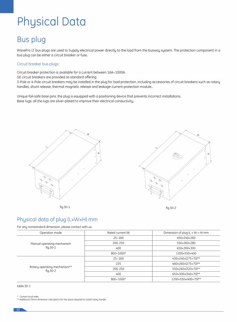
Bus plugWavePro LT bus plugs are used to Supply electrical power directly to the load from the busway system. The protection component in a bus plug can be either a circuit breaker or fuse.
Circuit breaker bus plugs:
Circuit breaker protection is available for a current between 16A~1000A. GE circuit breakers are provided as standard offering. 3-Pole or 4-Pole circuit breakers may be installed in the plug for load protection, including accessories of circuit breakers such as rotary handles, shunt release, thermal magnetic release and leakage-current protection module..
Unique fail-safe base pins: the plug is equipped with a positioning device that prevents incorrect installations.Base lugs: all the lugs are silver-plated to improve their electrical conductivity.
fig.30-1
L
w
H
Physical Data
L
w
Hfig.30-2
Physical data of plug (L×W×H) mmFor any nonstandard dimension, please contact with us.
Operation mode Rated current (A) Dimension of plug (L × W × H) mm
Manual operating mechanismfig.30-1
25~160 450×240×260
200, 250 550×260×280
400 650×300×300
800~1000* 1200×550×400
Rotary operating mechanism**fig.30-2
25~160 430×240×(275+70)**
225 460×260×(275+70)**
200, 250 550×260×(320+70)**
400 650×300×(340+70)**
800~1000* 1200×550×(400+70)**
table.30-1
* Contact local sales.** Additional 70mm dimension indicated is for the space required to install rotary handle.
31
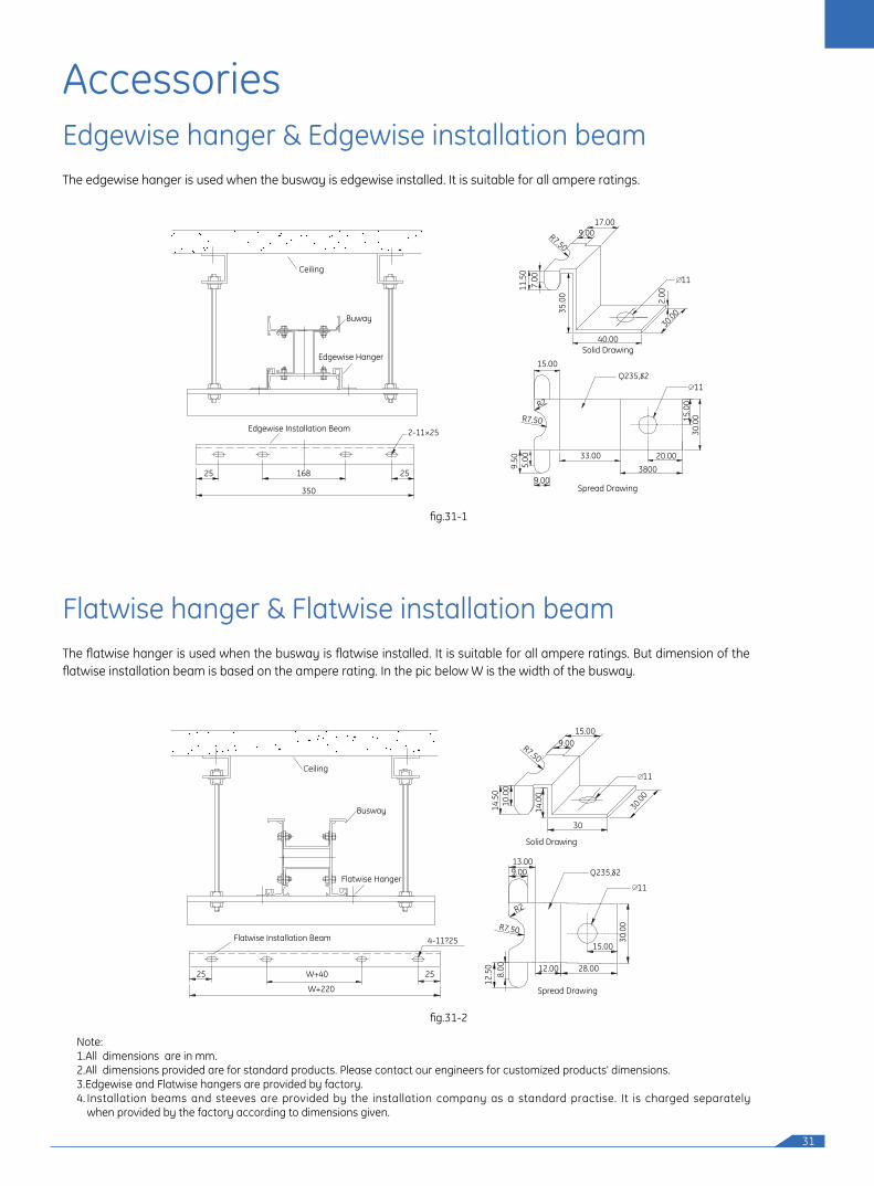
Edgewise hanger & Edgewise installation beamThe edgewise hanger is used when the busway is edgewise installed. It is suitable for all ampere ratings.
Flatwise hanger & Flatwise installation beamThe flatwise hanger is used when the busway is flatwise installed. It is suitable for all ampere ratings. But dimension of the flatwise installation beam is based on the ampere rating. In the pic below W is the width of the busway.
Accessories
Ceiling
Buway
17.009.00
11.5
07.
00
35.0
0
40.00
2.00
30.00
R7.50
Edgewise Hanger
Edgewise Installation Beam
Solid Drawing
15.00
9.50 5.00
9.00
33.003800
20.00
30.0
015.0
0
Spread Drawing
R2
R7.50
25 25168
350
2-11×25
11
11
Ceiling
15.009.00
Solid Drawing
13.009.00
R2
R7.50
Spread Drawing
30
30.00
14.5
0
14.0
0
11
10.0
0
R7.50
Busway
Flatwise Hanger
Flatwise Installation Beam
25
12.5
08.
00 12.00 28.00
15.00
30.0
0
25 W+40
W+220
4-11?25
11
fig.31-1
fig.31-2
Note:1. All dimensions are in mm.2. All dimensions provided are for standard products. Please contact our engineers for customized products' dimensions.3. Edgewise and Flatwise hangers are provided by factory.4. Installation beams and steeves are provided by the installation company as a standard practise. It is charged separately
when provided by the factory according to dimensions given.
32
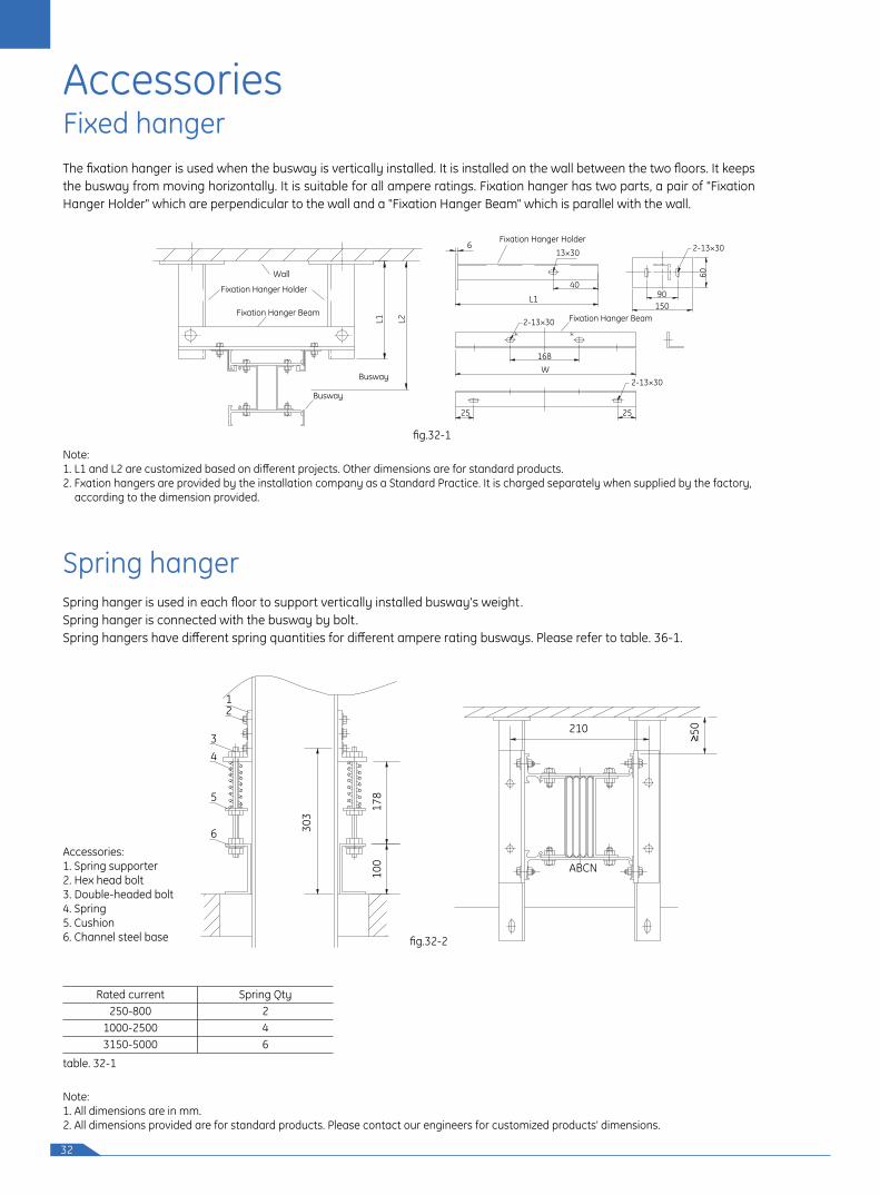
Fixed hangerThe fixation hanger is used when the busway is vertically installed. It is installed on the wall between the two floors. It keeps the busway from moving horizontally. It is suitable for all ampere ratings. Fixation hanger has two parts, a pair of "Fixation Hanger Holder" which are perpendicular to the wall and a "Fixation Hanger Beam" which is parallel with the wall.
Wall
6Fixation Hanger Holder
13×30
2-13×30
168W
Fixation Hanger Beam
40
60
90150
L1
2-13×30
2-13×30
25 25
Fixation Hanger Holder
Fixation Hanger Beam
Busway
BuswayL1 L2
fig.32-1
Note: 1. L1 and L2 are customized based on different projects. Other dimensions are for standard products.2. Fxation hangers are provided by the installation company as a Standard Practice. It is charged separately when supplied by the factory, according to the dimension provided.
Accessories
Spring hangerSpring hanger is used in each floor to support vertically installed busway's weight.Spring hanger is connected with the busway by bolt.Spring hangers have different spring quantities for different ampere rating busways. Please refer to table. 36-1.
Accessories: 1. Spring supporter2. Hex head bolt3. Double-headed bolt4. Spring5. Cushion6. Channel steel base
Note:1. All dimensions are in mm.2. All dimensions provided are for standard products. Please contact our engineers for customized products' dimensions.
12
34
303
178
210
ABCN100
5
6
fig.32-2
table. 32-1
Rated current Spring Qty250-800 2
1000-2500 43150-5000 6
33
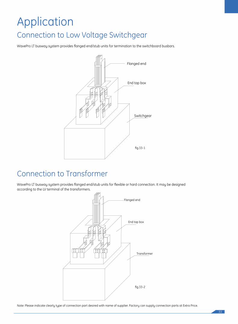
Note: Please indicate clearly type of connection part desired with name of supplier. Factory can supply connection parts at Extra Price.
ApplicationConnection to Low Voltage Switchgear
Connection to Transformer
WavePro LT busway system provides flanged end/stub units for termination to the switchboard busbars.
WavePro LT busway system provides flanged end/stub units for flexible or hard connection. It may be designed according to the LV terminal of the transformers.
Flanged end
End tap box
Switchgear
Flanged end
End tap box
Transformer
fig.33-1
fig.33-2
34
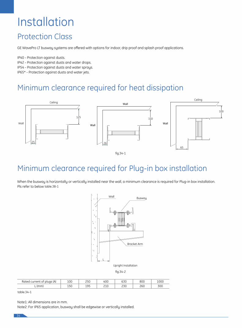
Minimum clearance required for heat dissipation
Protection Class
Installation
GE WavePro LT busway systems are offered with options for indoor, drip proof and splash proof applications.
IP40 - Protection against dusts.IP42 - Protection against dusts and water drops. IP54 - Protection against dusts and water sprays.IP65* - Protection against dusts and water jets.
When the busway is horizontally or vertically installed near the wall, a minimum clearance is required for Plug-in box installation.Pls refer to below table.38-1
Minimum clearance required for Plug-in box installation
Ceiling
Wall
125
25
Wall
Wall
150
26
Ceiling
Wall
100
65
fig.34-1
fig.34-2
table.34-1
Rated current of plugs (A) 100 250 400 630 800 1000L (mm) 150 195 210 230 260 300
Bracket Arm
Upright Installation
BuswayWall
L
Note1: All dimensions are in mm.Note2: For IP65 application, busway shall be edgewise or vertically installed.
35
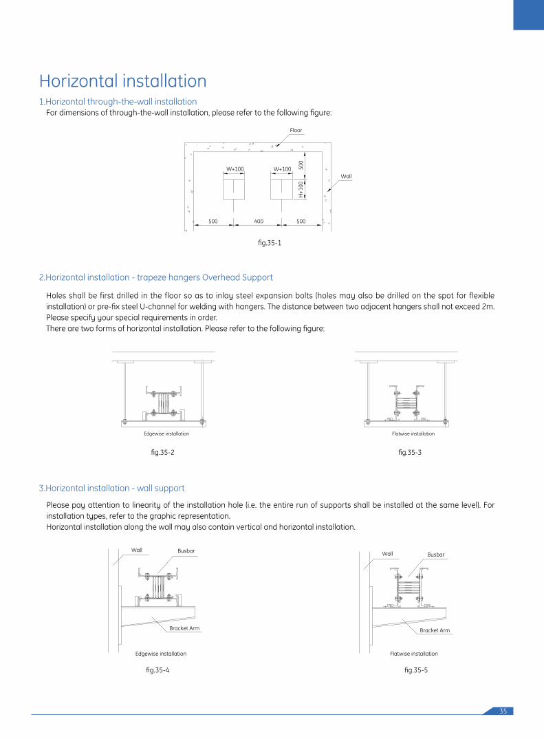
Horizontal installation1.Horizontal through-the-wall installation
3.Horizontal installation - wall support
2.Horizontal installation - trapeze hangers Overhead Support
For dimensions of through-the-wall installation, please refer to the following figure:
Please pay attention to linearity of the installation hole (i.e. the entire run of supports shall be installed at the same level). For installation types, refer to the graphic representation. Horizontal installation along the wall may also contain vertical and horizontal installation.
Holes shall be first drilled in the floor so as to inlay steel expansion bolts (holes may also be drilled on the spot for flexible installation) or pre-fix steel U-channel for welding with hangers. The distance between two adjacent hangers shall not exceed 2m. Please specify your special requirements in order. There are two forms of horizontal installation. Please refer to the following figure:
500 500
Floor
Wall
400
W+100
H+1
00
W+100 500
Edgewise installation Flatwise installation
BusbarWall
Bracket Arm
Edgewise installation
BusbarWall
Bracket Arm
Flatwise installation
fig.35-1
fig.35-2 fig.35-3
fig.35-4 fig.35-5
36
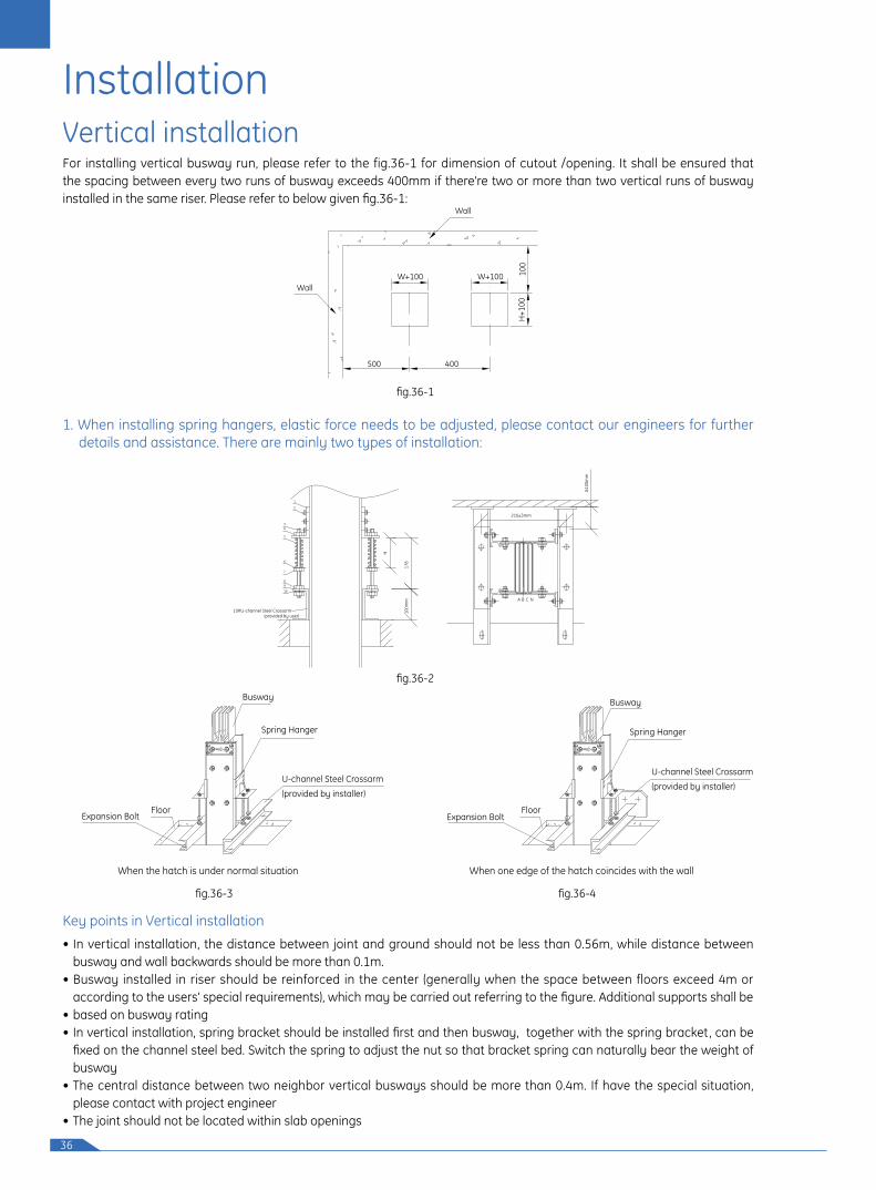
Vertical installationFor installing vertical busway run, please refer to the fig.36-1 for dimension of cutout /opening. It shall be ensured that the spacing between every two runs of busway exceeds 400mm if there're two or more than two vertical runs of busway installed in the same riser. Please refer to below given fig.36-1:
1. When installing spring hangers, elastic force needs to be adjusted, please contact our engineers for further details and assistance. There are mainly two types of installation:
Wall
500
WallW+100
400
W+100
H+1
0010
0
fig.36-1
fig.36-2
CA B N
1
2
3
5
8
6
H
178
210±3mm
≥100
mm
100m
m
10#U-channel Steel Crossarm(provided by user)
4
7
910
• In vertical installation, the distance between joint and ground should not be less than 0.56m, while distance between busway and wall backwards should be more than 0.1m.
• Busway installed in riser should be reinforced in the center (generally when the space between floors exceed 4m or according to the users' special requirements), which may be carried out referring to the figure. Additional supports shall be
• based on busway rating• In vertical installation, spring bracket should be installed first and then busway, together with the spring bracket, can be
fixed on the channel steel bed. Switch the spring to adjust the nut so that bracket spring can naturally bear the weight of busway
• The central distance between two neighbor vertical busways should be more than 0.4m. If have the special situation, please contact with project engineer
• The joint should not be located within slab openings
Key points in Vertical installation
fig.36-3
Floor
Spring Hanger
Expansion Bolt
Busway
U-channel Steel Crossarm
(provided by installer)
When the hatch is under normal situation
fig.36-4
Installation
Floor
Spring Hanger
Expansion Bolt
Busway
When one edge of the hatch coincides with the wall
U-channel Steel Crossarm
(provided by installer)
37
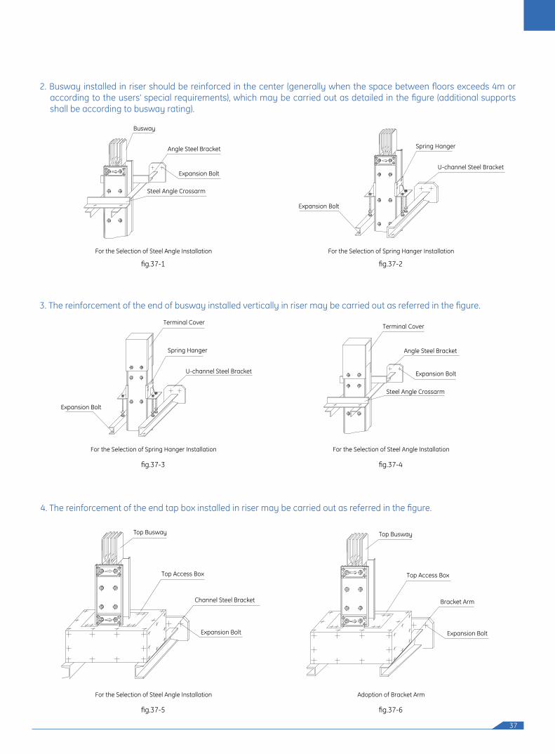
2. Busway installed in riser should be reinforced in the center (generally when the space between floors exceeds 4m or according to the users' special requirements), which may be carried out as detailed in the figure (additional supports shall be according to busway rating).
3. The reinforcement of the end of busway installed vertically in riser may be carried out as referred in the figure.
fig.37-1
Expansion Bolt
Busway
Angle Steel Bracket
Steel Angle Crossarm
For the Selection of Steel Angle Installation
fig.37-3
Spring Hanger
Terminal Cover
Expansion Bolt
U-channel Steel Bracket
For the Selection of Spring Hanger Installation
fig.37-4
Terminal Cover
Angle Steel Bracket
Steel Angle Crossarm
Expansion Bolt
For the Selection of Steel Angle Installation
fig.37-2
Spring Hanger
U-channel Steel Bracket
Expansion Bolt
For the Selection of Spring Hanger Installation
4. The reinforcement of the end tap box installed in riser may be carried out as referred in the figure.
fig.37-5 fig.37-6
Top Access Box
Expansion Bolt
Top Busway
Channel Steel Bracket Bracket Arm
Top Access Box
Expansion Bolt
Top Busway
For the Selection of Steel Angle Installation Adoption of Bracket Arm
38
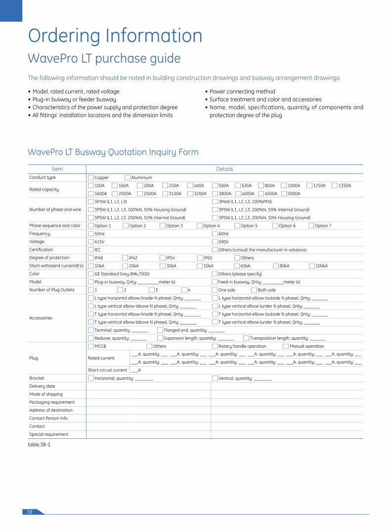
Ordering InformationWavePro LT purchase guide
WavePro LT Busway Quotation Inquiry Form
• Model, rated current, rated voltage • Plug-in busway or feeder busway• Characteristics of the power supply and protection degree• All fittings' installation locations and the dimension limits
• Power connecting method• Surface treatment and color and accessories• Name, model, specifications, quantity of components and
protection degree of the plug
The following information should be noted in building construction drawings and busway arrangement drawings:
table.38-1
Item DetailsConduct type Copper Aluminium
Rated capacity 100A 160A 200A 250A 400A 500A 630A 800A 1000A 1250A 1350A
1600A 2000A 2500A 3150A 3200A 3800A 4000A 4500A 5000A
Number of phase and wire
3P3W (L1, L2, L3) 3P4W (L1, L2, L3, 100%PEN)
3P5W (L1, L2, L3, 100%N, 50% Housing Ground) 3P5W (L1, L2, L3, 100%N, 50% Internal Ground)
3P5W (L1, L2, L3, 200%N, 50% Internal Ground) 3P5W (L1, L2, L3, 200%N, 50% Housing Ground)
Phase sequence and color Option 1 Option 2 Option 3 Option 4 Option 5 Option 6 Option 7
Frequency 50Hz 60Hz
Voltage 415V 690V
Certification IEC Others (consult the manufacturer in advance)
Degree of protection IP40 IP42 IP54 IP65 Others
Short withstand current@1s 10kA 20kA 30kA 50kA 65kA 80kA 100kA
Color GE Standard Grey (RAL7000) Others (please specify)
Model Plug-in busway, Qnty: _________meter (s) Feed-in busway, Qnty: _________meter (s)
Number of Plug Outlets 1 2 3 4 One side Both side
Accessories
L type horizontal elbow (inside N phase), Qnty: _______ L type horizontal elbow (outside N phase), Qnty: _______
L type vertical elbow (above N phase), Qnty: _______ L type vertical elbow (under N phase), Qnty: _______
T type horizontal elbow (inside N phase), Qnty: _______ T type horizontal elbow (outside N phase), Qnty: _______
T type vertical elbow (above N phase), Qnty: _______ T type vertical elbow (under N phase), Qnty: _______
Terminal, quantity: _______ Flanged end, quantity: _______
Reducer, quantity: _______ Expansion length, quantity: _______ Transposition length, quantity: _______
Plug
MCCB Others Rotary handle operation Manual operation
Rated current___A, quantity: ___ ___A, quantity: ___ ___A, quantity: ___ ___A, quantity: ___ ___A, quantity: ___ ___A, quantity: ___
___A, quantity: ___ ___A, quantity: ___ ___A, quantity: ___ ___A, quantity: ___ ___A, quantity: ___ ___A, quantity: ___
Short-circuit current ___A
Bracket Horizontal, quantity: ________ Vertical, quantity: ________
Delivery date
Mode of shipping
Packaging requirement
Address of destination
Contact Person Info.
Contact
Special requirement
39
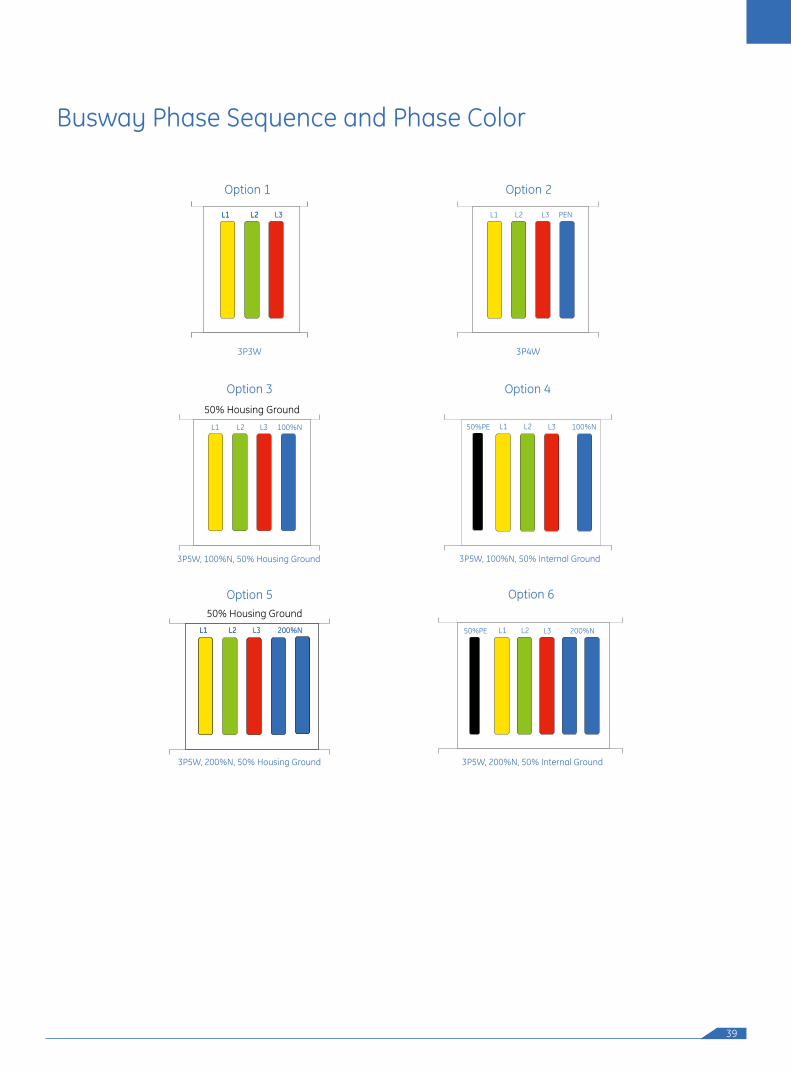
Busway Phase Sequence and Phase Color
3P3W
L1 L2 L3L1 L2L1 L2 L3
Option 1
L1 L2 NL3 100%
50% Housing Ground
3P5W, 100%N, 50% Housing Ground
Option 3
L1 L2 L3 PEN
3P4W
Option 2
Option 6
L2L150%PE L3 200%N
3P5W, 200%N, 50% Housing Ground
Option 550% Housing Ground
L1 L2 L3 200%NL1 L2L1 L2 L3 200%N
Option 4
L2L150%PE L3 100%N
3P5W, 100%N, 50% Internal Ground
3P5W, 200%N, 50% Internal Ground

40
WavePro LT
BWT F1 CSLN 1 00A
Busway
F1 Feeder & Accessories For feeder
(joint beyond)
F2 Joint
P1 Plug-in with 1 plug outlet
P2 Plug-in with 2 plug outlets
P3 Plug-in with 3 plug outlets
P4 Plug-in (with 4 plug outlets)
P6 Plug-in with 6 plug outlets
P8 Plug-in with 8 plug outlets
1 3P3W L1 L2 L3
2 3P4W L1 L2 L3 PEN
3 3P5W L1 L3, 100%N,
50% Housing Ground)
4 3P5W L1 L3, 100%N,
50% Internal Ground)
5 3P5W L1 L3, 200%N,
50% Housing Ground)
6 3P5W L1 L3, 200%N,
50% Internal Ground)
40
40 IP4042 IP4254 IP5465 IP6500 Spring
Hangerand Outlet
C
C CuA Al
CSLN Straight Length
CFEN Flanged End
CTCN Terminal Cover
LEIN Edgewise Elbow N Phase Inboard
LEIF Edgewise Elbow with Flanged End N Phase Inboard
LEON Edgewise Elbow N Phase Outboard
LEOF Edgewise Elbow with Flanged End N Phase Outboard
LFNN Flatwise Elbow
LFUF Flatwise Elbow with Flanged End N Phase Up
LFDF Flatwise Elbow with Flanged End N Phase Down
ZFNN Edgewise Offset
ZFUN Flatwise Offset N Phase Up
ZFDN Flatwise Offset N Phase Down
TEIN Edgewise T N Phase Inboard
TEON Edgewise T N Phase Outboard
TFNN Flatwise T
CFNN Flatwise Cross
CENN Edgewise Cross
TREN Reducer
ELNN Expansion Length
TPLN Transposition Length
OTHR Other
SPHR Spring Hanger
OTLT Outlet
00 100A
01 160A
02 200A
03 250A
04 400A
05 500A
06 630A
08 800A
10 1000A
12 1250A
13 1350A
16 1600A
20 2000A
25 2500A
32
38 3800A
40 4000A
45 4500A
50 5000A
NAA Outlet
3150A31
3200A
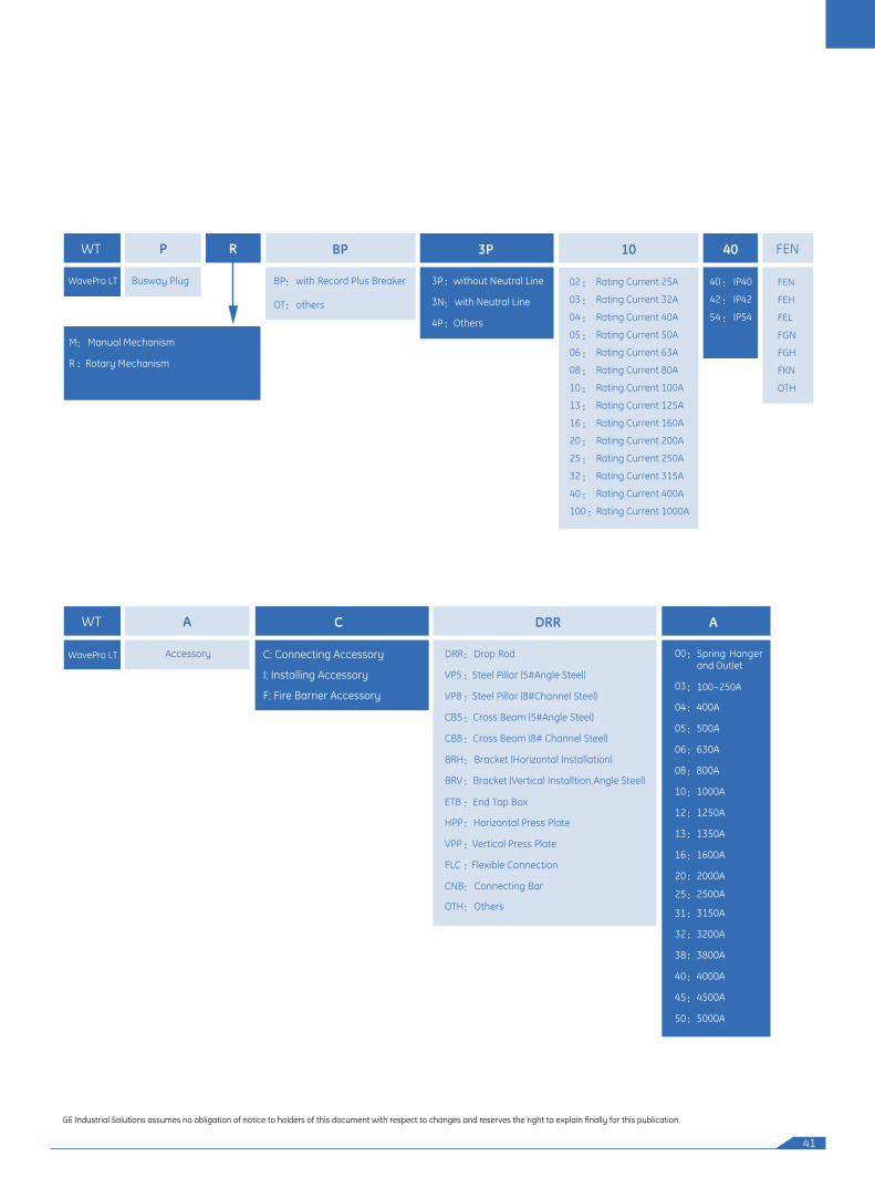
WavePro LT Busway System Catalog Ordering NumbersWavePro LT Busway System can be ordered by catalog numbers. Please refer to the following catalog number system and contact our engineers to place orders.
41
WavePro LT
P R 40
Busway Plug
M Manual Mechanism
R Rotary Mechanism
WavePro LT
A C DRR A
Accessory 00
03
04 400A
05 500A
06 630A
08 800A
10 1000A
12 1250A
13 1350A
16 1600A
20 2000A
25 2500A
32
38 3800A
40 4000A
45 4500A
50 5000A
3150A31
3200A
GE Industrial Solutions assumes no obligation of notice to holders of this document with respect to changes and reserves the right to explain finally for this publication.
C: Connecting Accessory
I: Installing Accessory
F: Fire Barrier Accessory
)
DRR Drop Rod
VP5 Steel Pillar (5#Angle Steel)
VP8 Steel Pillar (8#Channel Steel)
CB5 Cross Beam (5#Angle Steel)
CB8 Cross Beam (8# Channel Steel)
BRH Bracket (Horizontal Installation)
BRV Bracket (Vertical Installtion,Angle Steel
HPP Horizontal Press Plate
VPP Vertical Press Plate
FLC Flexible Connection
CNB Connecting Bar
OTH Others
BP 3P 10
BP with Record Plus Breaker
OT others
3P without Neutral Line
3N with Neutral Line
4P Others
02 : Rating Current 25A
03 : Rating Current 32A
04 : Rating Current 40A
05 : Rating Current 50A
06 : Rating Current 63A
08 : Rating Current 80A
10 : Rating Current 100A
13 : Rating Current 125A
16 : Rating Current 160A
20 : Rating Current 200A
25 : Rating Current 250A
32 : Rating Current 315A
40 : Rating Current 400A
100 : Rating Current 1000A
40 : IP40
42 : IP42
54 : IP54
WT FEN
WT
FEN
FEH
FEL
FGN
FGH
FKN
OTH
Spring Hanger and Outlet
100~250A
ETB End Tap Box
REGIONAL OFFICES
NORTH
BRANCH OFFICES
Gurgaon
GE India Industrial Pvt. Ltd.5th Floor, Building No.7A DLF Cyber City, DLF Phase-IIISector 25 A, GurgaonHaryana – 122002Ph: (0124) 4808000Fax: (0124) 4226911 / 4226912
Chandigarh
GE India Industrial Pvt. Ltd.SCO No. 72 & 73, First FloorSector 8/C, Madhya MargChandigarh-160008Ph: (0172) 3982908-10Fax: (0172) 3982905
Lucknow
GE India Industrial Pvt. Ltd.101, Ace Business Center19, Vidhan Sabha MargLucknow-226001Ph: (0522) 3203808, 3012444/666Fax: (0522) 4045909
SOUTH
Bangalore
GE India Industrial Pvt. Ltd.The Millenia, Level-6, Tower B1 & 2, Murphy Road, UlsoorBangalore-560008Ph: (080) 41434000Fax: (080) 41434199
Chennai
GE India Industrial Pvt. Ltd.Temple Tower, 6th Floor476, (New No. 672) Anna SalaiNandanamChennai-600035Ph: (044) 45070470-84Fax: (044) 45070474
Coimbatore
GE India Industrial Pvt. Ltd.No.36/6 & 7, 1st FloorAshirwad BuildingD.B.Road, R.S. PuramCoimbatore-641002Ph: (0422) 4393520 / 4393529
WEST
Mumbai
GE India Industrial Pvt. Ltd.361/362, Solitaire Corporate ParkM. Vasanji Road, ChakalaAndheri (E), Mumbai-400093Ph: (022) 40101610Fax: (022) 40101611
EAST
Kolkata
GE India Industrial Pvt. Ltd.Horizon Building, 4th Floor 57, Chowringhee RoadKolkata-700071Ph: (033) 40034056Fax: (033) 40034071
Works:GE India Industrial Pvt. Ltd.Plot No. 42/1 & 45/14Electronic City - Phase IIBangalore-560100Ph: (080) 41113000Fax: (080) 28528469/552
HO:GE India Industrial Pvt. Ltd.The Millenia, Level-6, Tower B1 & 2, Murphy Road, UlsoorBangalore-560008Ph: (080) 41434000Fax: (080) 41434199Email: [email protected]
Toll Free No:18001024343
Customer Care:[email protected]
g and General Electric are registered trade marks of General Electric Co. USA©
Ahmedabad
GE India Industrial Pvt. Ltd.405-406, Kirtiman ComplexKinariwala House, Behind CitibankOff C.G. Road, Ahmedabad-380006Ph: (079) 65427385/65427389Fax: (079) 26460637
Pune
GE Money Financial Services LimitedShop No. 405-410, 4th FloorCity Point, Dhole Patil RoadPune-411001Ph: (020) 41266999Fax: (020) 41266109
Cochin
GE India Industrial Pvt. Ltd.Mayur Business Center & MotelChittur Road, Pullepadi JunctionCochin-682035Ph: (0484) 2364139Fax: (0484) 4031400
Hyderabad
GE India Industrial Pvt. Ltd.5-2-45, Hyderbasti, RP RoadNear Gujarati High SchoolSecunderabad-500003Ph: (040) 27543162, 66311264Fax: (040) 66339272
We are committed to continuous development and improvement of our products and the specifications aresubject to change without notice. For product availability and latest prices, please contact GE Sales Team.
For any further information, visit us at http://www.geindustrial.com
1204
/BU
SWAY
S/CA
T/LT