WAVE-IN-DECK LOAD ON A JACKET PLATFORM, CFD …veldman/preprints/OMAE2009-79053.pdf · WAVE-IN-DECK...
10
Proceedings of the ASME 28th International Conference on Ocean, Offshore and Arctic Engineering OMAE2009 May 31 - June 5, 2009, Honolulu, Hawaii, USA OMAE2009-79053 WAVE-IN-DECK LOAD ON A JACKET PLATFORM, CFD-DERIVED PRESSURES AND NON-LINEAR STRUCTURAL RESPONSE Bogdan Iwanowski * FORCE Technology Norway AS Claude Monets alle 5 1338 Sandvika Norway Email: [email protected] Rune Gladsø FORCE Technology Norway AS Email: [email protected] Marc Lefranc FORCE Technology Norway AS Email: [email protected] ABSTRACT The paper presents an industrial application of CFD and non-linear structural response codes in offshore technology. A Wave-In-Deck load due to an extreme wave, acting on a jacket platform, is studied numerically. Particular attention is given to details of local flow and local non-linear dynamical response of the structure. A very detailed FEM model of the platform deck struc- ture, composed of shell elements, is embedded into a non body- conforming CFD grid of computational cells. The applied CFD code is a Navier-Stokes equation solver with an improved Volume of Fluid (iVOF) method employed to displace and re-construct fluid’s free surface and uses a simple, Cartesian grid. The two computational grids, FEM and CFD, are independent. The challenge of a direct mapping of CFD-derived fluid pressures onto structural FEM shell elements is addressed. Then the non-linear dynamical response of the structure is found in time domain. The employed CFD code is ComFLOW while the FEM part is handled by the well-known commercial program LS- DYNA. The composed approach utilizes both robustness of VOF- based methods in tracking of the fluid’s free surface and reliabil- ity of FEM structural codes such as LS-DYNA. * Address all correspondence to this author. INTRODUCTION A positive air gap between design wave crest and platform’s deck is no longer maintained for a number of installed offshore platforms of jacket type. Reasons for the insufficient air gap can be twofold: updated environmental wave data parameters and seabed subsidence at the platform’s location. It follows that such platforms can suffer a severe wave-in- deck impact with high inundation, understood here as the wave impact height. Structural reassessment of the platform requires an estimation of loads acting on the structure. In a preliminary analysis, the loads can be taken as total fluid forces acting on the entire platform deck. Such overall horizontal and vertical forces can be predicted either by methods based on fluid’s momentum displacement considerations or by a more advanced CFD analy- sis. The momentum displacement methods are quick, but require a well-chosen set of coefficients (inertia, drag, shielding). The coefficients can be found and calibrated through expensive ex- periments [1], but otherwise their values are educated guesses only. Detailed and very localised time-pressure histories cannot, in general, be obtained by the momentum displacement meth- ods. However, one can apply a CFD code, where no iner- tia/drag/shielding coefficients are involved. This makes the CFD approach more robust and reliable, but one has to pay for the in- creased reliability by much longer calculations. A comparison of wave-in-deck fluid forces predicted by the momentum displace- ment method and with a very basic CFD calculations for a simple box structural model can be found in [2]. The agreement was en- 1 Copyright c 2009 by ASME
Transcript of WAVE-IN-DECK LOAD ON A JACKET PLATFORM, CFD …veldman/preprints/OMAE2009-79053.pdf · WAVE-IN-DECK...
Proceedings of the ASME 28th International Conference on Ocean, Offshore and Arctic EngineeringOMAE2009
May 31 - June 5, 2009, Honolulu, Hawaii, USA
OMAE2009-79053
WAVE-IN-DECK LOAD ON A JACKET PLATFORM, CFD-DERIVEDPRESSURES AND NON-LINEAR STRUCTURAL RESPONSE
Bogdan Iwanowski∗FORCE Technology Norway AS
Claude Monets alle 51338 Sandvika
NorwayEmail: [email protected]
Rune GladsøFORCE Technology Norway AS
Email: [email protected]
Marc LefrancFORCE Technology Norway AS
Email: [email protected]
ABSTRACT
The paper presents an industrial application of CFD andnon-linear structural response codes in offshore technology. AWave-In-Deck load due to an extreme wave, acting on a jacketplatform, is studied numerically. Particular attention is given todetails of local flow and local non-linear dynamical response ofthe structure.
A very detailed FEM model of the platform deck struc-ture, composed of shell elements, is embedded into a non body-conforming CFD grid of computational cells. The applied CFDcode is a Navier-Stokes equation solver with an improved Volumeof Fluid (iVOF) method employed to displace and re-constructfluid’s free surface and uses a simple, Cartesian grid. The twocomputational grids, FEM and CFD, are independent.
The challenge of a direct mapping of CFD-derived fluidpressures onto structural FEM shell elements is addressed. Thenthe non-linear dynamical response of the structure is found intime domain. The employed CFD code is ComFLOW while theFEM part is handled by the well-known commercial program LS-DYNA. The composed approach utilizes both robustness of VOF-based methods in tracking of the fluid’s free surface and reliabil-ity of FEM structural codes such as LS-DYNA.
∗Address all correspondence to this author.
INTRODUCTIONA positive air gap between design wave crest and platform’s
deck is no longer maintained for a number of installed offshoreplatforms of jacket type. Reasons for the insufficient air gap canbe twofold: updated environmental wave data parameters andseabed subsidence at the platform’s location.
It follows that such platforms can suffer a severe wave-in-deck impact with high inundation, understood here as the waveimpact height. Structural reassessment of the platform requiresan estimation of loads acting on the structure. In a preliminaryanalysis, the loads can be taken as total fluid forces acting on theentire platform deck. Such overall horizontal and vertical forcescan be predicted either by methods based on fluid’s momentumdisplacement considerations or by a more advanced CFD analy-sis. The momentum displacement methods are quick, but requirea well-chosen set of coefficients (inertia, drag, shielding). Thecoefficients can be found and calibrated through expensive ex-periments [1], but otherwise their values are educated guessesonly.
Detailed and very localised time-pressure histories cannot,in general, be obtained by the momentum displacement meth-ods. However, one can apply a CFD code, where no iner-tia/drag/shielding coefficients are involved. This makes the CFDapproach more robust and reliable, but one has to pay for the in-creased reliability by much longer calculations. A comparison ofwave-in-deck fluid forces predicted by the momentum displace-ment method and with a very basic CFD calculations for a simplebox structural model can be found in [2]. The agreement was en-
1 Copyright c© 2009 by ASME
couraging for the incoming wave of Stokes 5th order type. Morerecently, the wave-in-deck impact problem has been addressedin [3, 4].
MotivationConsequences of global wave-in-deck impact with respect
to a jacket structure have been evaluated in the last 15 years. Thedeck structure itself has not been given a similar attention; eventhough a collapse of the topside super-structure would result insimilar consequences for the platform.
Decks of the jacket platforms have not been designed forwave in deck loads since such load type was not anticipated.Hence it is nearly impossible to document ability of a jacket plat-form’s deck to withstand this kind of wave load by traditionalcalculation according to currently existing regulations, such asNORSOK standards [5, 6], or by following the “best practiceguidelines” such as an outcome of the ULTIGUIDE JIP [7].
A new approach for more accurate evaluation of structuralintegrity of the deck structure has been developed. The presentedmethodology uses the latest available possibilities with respectto load estimation and structural response calculation. Wave-in-deck loads are predicted with the CFD code and fluid pressuresare directly mapped onto a structural Finite Element grid com-posed of shell elements. The following FEM analysis finds anon-linear dynamical response of the deck structure, and finalresults include strains within all modelled structural parts.
The goal is to document that the platform deck structure canwithstand the wave-in-deck load, that the safety requirements aremaintained, and that there is no high risk of pollution due to anoil spill. Depending of the strain utilization level of the deck’sstructural parts, a suitable local reinforcement can be proposed.
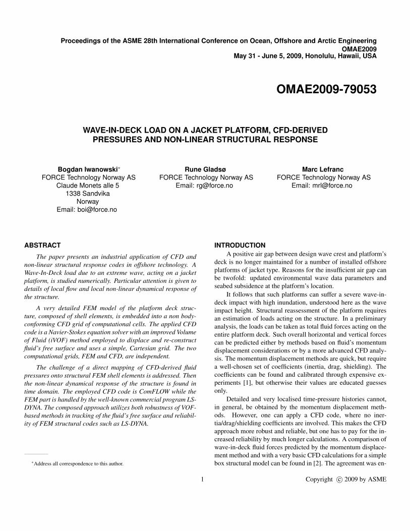
METHODOLOGYThe wave-in-deck problem for a jacket platform is schemat-
ically depicted in Fig. 1. Several CFD techniques can be usedto find fluid flow around the platform’s deck. The applied CFDmethod should be capable of finding complex fluid’s free sur-face deformations. Examples of successful free surface trackingtechniques are Volume of Fluid (VOF) and Smooth Particle Hy-drodynamics (SPH). The former is an Eulerian formulation andrequires a 3D fluid grid, which either conforms to the body shapeor is generated separately, being independent from the object’sgeometry. The purely Lagrangian SPH approach is grid-free andin principle can handle arbitrarily complex body shapes.
The above methods are all computationally intensive. In theEulerian formulations, the entire fluid domain must be griddedwith a sufficient accuracy in order to resolve very complex flowfeatures. Likewise, the fluid domain must be filled with a suffi-cient number of Lagrangian SPH particles.
Hereafter, this article will concentrate on the Eulerian ap-
Figure 1. The wave-in-deck impact problem
proach. An application of the SPH to compute fluid flow aroundmarine structures is described, for example, in [8].
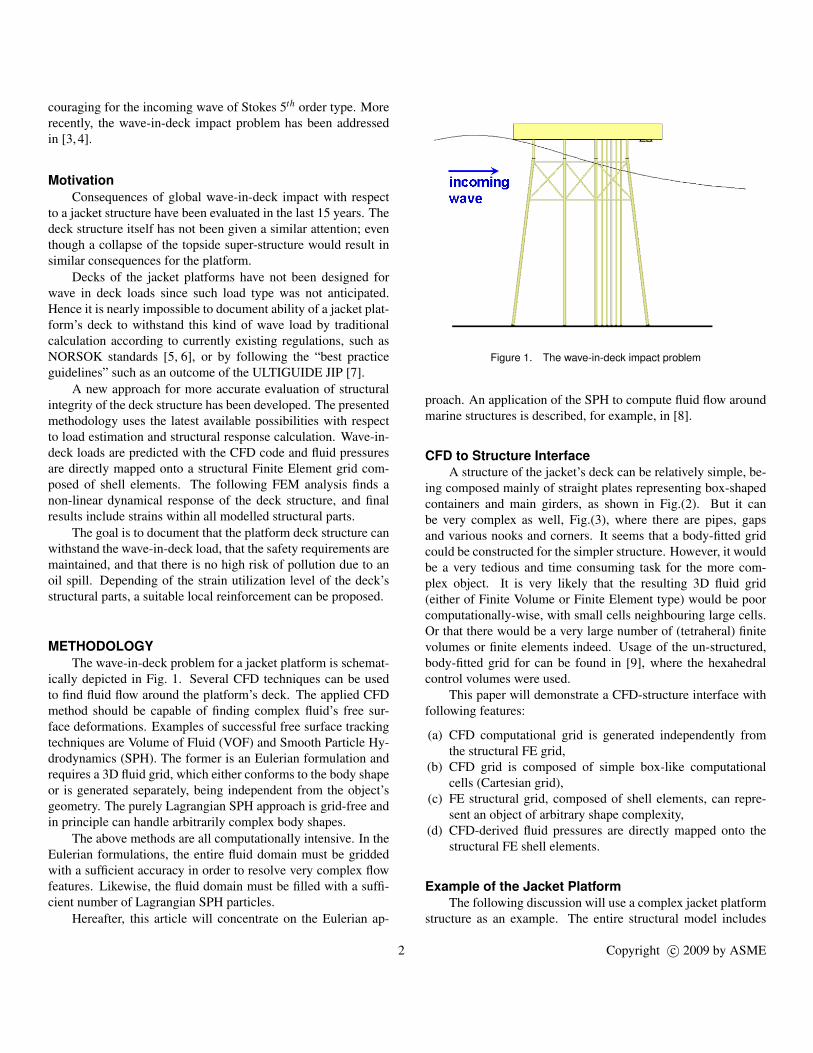
CFD to Structure InterfaceA structure of the jacket’s deck can be relatively simple, be-
ing composed mainly of straight plates representing box-shapedcontainers and main girders, as shown in Fig.(2). But it canbe very complex as well, Fig.(3), where there are pipes, gapsand various nooks and corners. It seems that a body-fitted gridcould be constructed for the simpler structure. However, it wouldbe a very tedious and time consuming task for the more com-plex object. It is very likely that the resulting 3D fluid grid(either of Finite Volume or Finite Element type) would be poorcomputationally-wise, with small cells neighbouring large cells.Or that there would be a very large number of (tetraheral) finitevolumes or finite elements indeed. Usage of the un-structured,body-fitted grid for can be found in [9], where the hexahedralcontrol volumes were used.
This paper will demonstrate a CFD-structure interface withfollowing features:
(a) CFD computational grid is generated independently fromthe structural FE grid,
(b) CFD grid is composed of simple box-like computationalcells (Cartesian grid),
(c) FE structural grid, composed of shell elements, can repre-sent an object of arbitrary shape complexity,
(d) CFD-derived fluid pressures are directly mapped onto thestructural FE shell elements.
Example of the Jacket PlatformThe following discussion will use a complex jacket platform
structure as an example. The entire structural model includes
2 Copyright c© 2009 by ASME
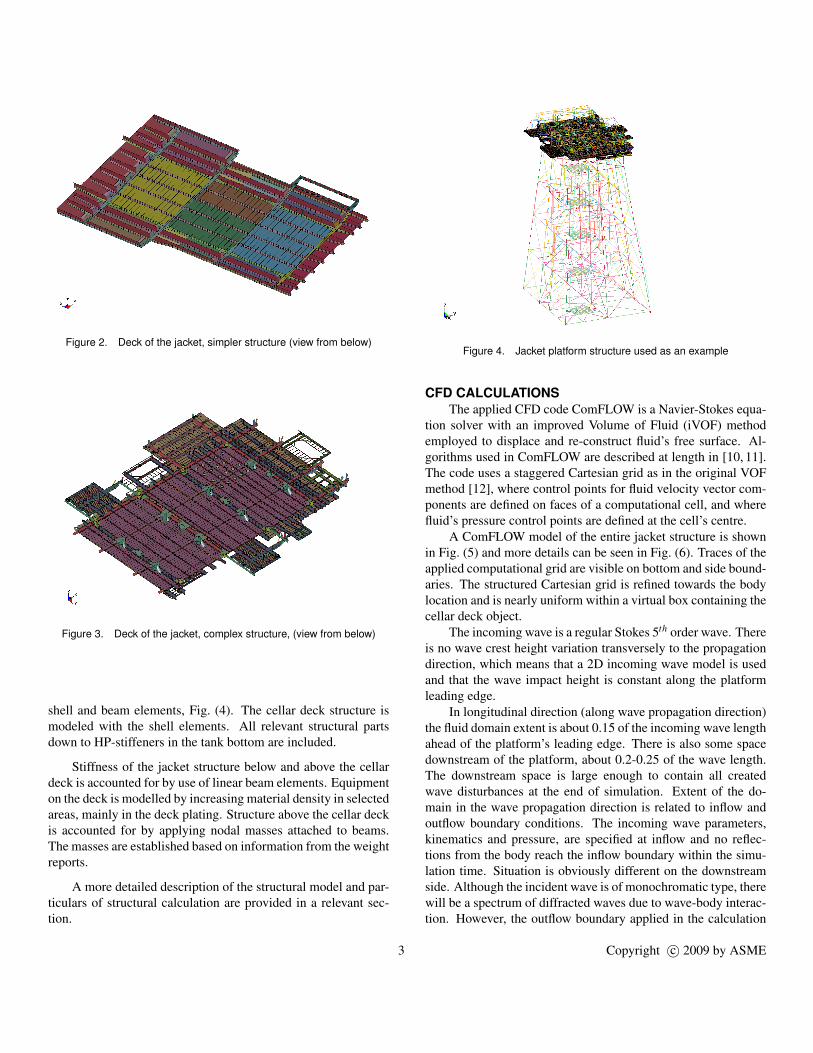
Figure 2. Deck of the jacket, simpler structure (view from below)
Figure 3. Deck of the jacket, complex structure, (view from below)
shell and beam elements, Fig. (4). The cellar deck structure ismodeled with the shell elements. All relevant structural partsdown to HP-stiffeners in the tank bottom are included.
Stiffness of the jacket structure below and above the cellardeck is accounted for by use of linear beam elements. Equipmenton the deck is modelled by increasing material density in selectedareas, mainly in the deck plating. Structure above the cellar deckis accounted for by applying nodal masses attached to beams.The masses are established based on information from the weightreports.
A more detailed description of the structural model and par-ticulars of structural calculation are provided in a relevant sec-tion.
Figure 4. Jacket platform structure used as an example
CFD CALCULATIONSThe applied CFD code ComFLOW is a Navier-Stokes equa-
tion solver with an improved Volume of Fluid (iVOF) methodemployed to displace and re-construct fluid’s free surface. Al-gorithms used in ComFLOW are described at length in [10, 11].The code uses a staggered Cartesian grid as in the original VOFmethod [12], where control points for fluid velocity vector com-ponents are defined on faces of a computational cell, and wherefluid’s pressure control points are defined at the cell’s centre.
A ComFLOW model of the entire jacket structure is shownin Fig. (5) and more details can be seen in Fig. (6). Traces of theapplied computational grid are visible on bottom and side bound-aries. The structured Cartesian grid is refined towards the bodylocation and is nearly uniform within a virtual box containing thecellar deck object.
The incoming wave is a regular Stokes 5th order wave. Thereis no wave crest height variation transversely to the propagationdirection, which means that a 2D incoming wave model is usedand that the wave impact height is constant along the platformleading edge.
In longitudinal direction (along wave propagation direction)the fluid domain extent is about 0.15 of the incoming wave lengthahead of the platform’s leading edge. There is also some spacedownstream of the platform, about 0.2-0.25 of the wave length.The downstream space is large enough to contain all createdwave disturbances at the end of simulation. Extent of the do-main in the wave propagation direction is related to inflow andoutflow boundary conditions. The incoming wave parameters,kinematics and pressure, are specified at inflow and no reflec-tions from the body reach the inflow boundary within the simu-lation time. Situation is obviously different on the downstreamside. Although the incident wave is of monochromatic type, therewill be a spectrum of diffracted waves due to wave-body interac-tion. However, the outflow boundary applied in the calculation
3 Copyright c© 2009 by ASME
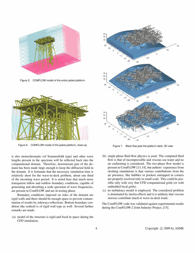
Figure 5. COMFLOW model of the entire jacket platform
Figure 6. COMFLOW model of the jacket platform, close-up
is also monochromatic (of Sommerfeldt type) and other wavelengths present in the spectrum will be reflected back into thecomputational domain. Therefore, downstream part of the do-main has been made large enough to keep the diffracted field inthe domain. It is fortunate that the necessary simulation time isrelatively short for the wave-in-deck problem, about one thirdof the incoming wave period. It is noted here that much moretransparent inflow and outflow boundary conditions, capable ofgenerating and absorbing a wide spectrum of wave frequencies,are present in ComFLOW and are in testing phase.
Boundary conditions imposed on sides of the domain arerigid walls and there should be enough space to prevent contam-ination of results by sideways reflections. Bottom boundary con-dition (the seabed) is of rigid wall type as well. Several furtherremarks are made:
(a) model of the structure is rigid and fixed in space during theCFD simulation,
Figure 7. Wave flow past the platform deck, 3D view
(b) single-phase fluid flow physics is used. The computed fluidflow is that of incompressible and viscous sea water and noair cushioning is considered. The two-phase flow model ispresent in ComFLOW [13,14], but authors’ experience fromsloshing simulations is that various contributions from theair presence, like bubbles or pockets entrapped in cornersare properly resolved only in small scale. This could be pos-sible only with very fine CFD computational grids (or withembedded local grids).
(c) no turbulence model is employed. The considered problemis dominated by inertia effects and it is unlikely that viscousstresses contribute much to wave-in-deck loads.
The ComFLOW code was validated against experimental resultsduring the ComFLOW-2 Joint Industry Project, [15].
4 Copyright c© 2009 by ASME

Figure 8. Wave flow past the platform deck, side view, part I
RESULTS OF CFD SIMULATIONVisualization of the CFD-computed fluid flow past the plat-
form deck is shown in a number of snapshots taken from fluidflow animation movies. The three frames shown in Fig. (7) dis-play stages of a simulation viewed from 3D perspective. It canbe seen that some amount of sea water overtops the platform’sdeck edge and enters the deck. Then, droplets of water runningout of the deck are visible in the last frame.
A more detailed fluid flow visualization is presented inFigs. (8) and (9). There are 8 consecutive stages of the simu-lated wave-in-deck phenomenon shown from a side view.
Mapping of CFD-derived PressuresLocal fluid pressures obtained from the CFD simulation are
available at centers of cells. A FE representation of the structureis simply submerged into the CFD computational grid at exactlocation of ComFLOW representation of the body, as shown inFig. (5). The first task is selection of CFD pressure points thatare the closest neighbours of structural elements. The submergedstructure is depicted in Fig. (10), and the selected CFD pressurepoints are shown as small dark squares in centres of CFD com-putational cells (the CFD grid is shown in background).
Each structural shell element has always a geometrical cen-tre and a normal vector defined. Only one more bit of informa-tion must be associated with an element. It must be explicitlystated which face of the shell element is exposed to the fluid flowand relation of the exposed face to the element’s normal. Thethree obvious possibilities are no exposed element faces (an in-ternal stiffener), one exposed face (wall of a bottom tank), twoexposed faces (an external girder). If the above information isavailable, then choice of the CFD pressure point relevant to a
Figure 9. Wave flow past the platform deck, side view, part II
given shell element can be fully automated. An example is pre-sented in Fig. (11), where all exposed shell elements of a com-plicated part of the jacket’s cellar deck structure have appropriateCFD pressure points assigned. It is noted that:
(a) rather large data sets must be processed. For a problem athand, the typically used CFD grid has 10-20 million of com-putational cells an there are typically 200-500 thousands ofFE shell elements,
(b) number of created time-pressure functions was, for thetested cases, in range of 100-200 thousands. Only a verylimited part of these functions can be eye-inspected,
(c) it helps that the used CFD computational grid is Cartesianand structured. But the pressure selection algorithm willwork with unstructured grids as well (and, although this wasnot tried, should work with the SPH particles).
Removal of Pressure PeaksThe iVOF method used in ComFLOW enforces mass con-
servation principle in grid cells that contain fluid’s free surfaceby a scheme which involves velocity extrapolation. This proce-dure is described in [10, 11] and typically performs very well.However, some pressure spikes occassionally do appear in com-puted time-pressure signals, especially in cells that are partiallyoccupied by the immersed body and where fluid’s free surfacehas just appeared or just vanished.
For the considered problem, cells of such type are presenteverywhere in vicinity of the jacket structure as the incomingwave passes through the platform’s deck location.
Since origin of the numerically induced pressure peaks isknown and explainable, it is justified to use a reasonably de-
5 Copyright c© 2009 by ASME

Figure 10. FE structure representation submerged into the CFD grid
Figure 11. Structural shell elements and assigned CFD pressure points
signed peak-removal and curve smoothing procedure. It has alsoben found that short-lasting pressure peaks have adverse effectson the transient structural response simulation.
The applied peak-removal and/or smoothing techniqueshould be rather delicate to avoid smoothing-out the truly ex-isting flow features. The procedure must be also fully automatic,since it is not possible to visually inspect all the derived time-pressure functions.
All time-pressure curves obtained from the ComFLOW sim-ulation have been post-processed by a multi-pass peak-removaland smoothing procedure. The data processing passes included:
1. re-sampling,2. removal of standalone peaks (pressure peaks with a very
short duration, like one CFD time step. Such peaks are con-sidered non-physical),
3. median filter.4. moving average filter with a Gauss or Kaiser window.
-0.5
0
0.5
1
1.5
2
2.5
3
0 1 2 3 4 5 6
Pre
ssu
re, [
bar
]
Time, [sec]
raw CFD datasmoothed
Figure 12. Smoothing of a CFD pressure signal, example A
-0.2
0
0.2
0.4
0.6
0.8
1
1.2
1.4
0 1 2 3 4 5 6
Pre
ssu
re, [
bar
]
Time, [sec]
raw CFD datasmoothed
Figure 13. Smoothing of a CFD pressure signal, example B
Two arbitrarily chosen examples of such data post-processing aredisplayed in Fig.(12) and Fig.(13). It can be seen that the origi-nal time-pressure signals (red colour curves) are somewhat shakyand that there are spikes. The post-processed pressure curves aredisplayed in blue colour.
CFD Results, PressureGraphs of the CFD-derived time-pressure functions are pre-
sented for two selected parts of the cellar deck structure. Shellelements within the deck’s leading edge and within externalgirders are shown in Fig.(14) and Fig.(15), while associatedpressure load curves are presented in Fig.(16) and Fig.(17), re-spectively. The graphs display rather typical impact-like time-pressure curves.
The loading pressures can be displayed over any part of thestructure as well. Spatial distribution of the fluid pressure on theentire deck’s bottom plating at some time instant is displayed inFig.(18).
6 Copyright c© 2009 by ASME
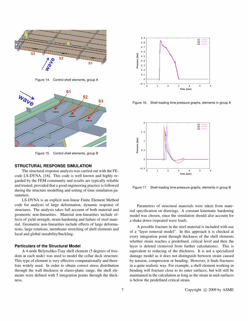
Figure 14. Control shell elements, group A
Figure 15. Control shell elements, group B
STRUCTURAL RESPONSE SIMULATIONThe structural response analysis was carried out with the FE-
code LS-DYNA, [16]. This code is well known and highly re-garded by the FEM community and results are typically reliableand trusted, provided that a good engineering practice is followedduring the structure modelling and setting of time simulation pa-rameters.
LS-DYNA is an explicit non-linear Finite Element Methodcode for analysis of large deformation, dynamic response ofstructures. The analysis takes full account of both material andgeometric non-linearities. Material non-linearities include ef-fects of yield strength, strain hardening and failure of steel mate-rial. Geometric non-linearities include effects of large deforma-tions, large rotations, membrane stretching of shell elements andlocal and global instability/buckling.
Particulars of the Structural ModelA 4-node Belytschko-Tsay shell element (5 degrees of free-
dom at each node) was used to model the cellar deck structure.This type of element is very effective computationally and there-fore widely used. In order to obtain correct stress distributionthrough the wall thickness in elasto-platic range, the shell ele-ments were defined with 5 integration points through the thick-ness.
-0.1
0
0.1
0.2
0.3
0.4
0.5
0.6
0.7
0.8
0.9
0 1 2 3 4 5 6
Pre
ssu
re, [
bar
]
Time, [sec]
S1S2S3
Figure 16. Shell-loading time-pressure graphs, elements in group A
-0.5
0
0.5
1
1.5
2
0 1 2 3 4 5 6
Pre
ssu
re, [
bar
]
Time, [sec]
S1S2S3
Figure 17. Shell-loading time-pressure graphs, elements in group B
Parameters of structural materials were taken from mate-rial specification on drawings. A constant kinematic hardeningmodel was chosen, since the simulation should also account fora shake down (repeated wave load).
A possible fracture in the steel material is included with useof a “layer removal model”. In this approach it is checked atevery integration point through thickness of the shell elementswhether strain reaches a predefined, critical level and then thelayer is deleted (removed from further calculations). This isequivalent to reducing of the thickness. It is not a specializeddamage model as it does not distinguish between strain causedby tension, compression or bending. However, it finds fracturesin a quite realistic way. For example, a shell element working inbending will fracture close to its outer surfaces, but will still bemaintained in the calculation as long as the strain in mid-surfacesis below the predefined critical strain.
7 Copyright c© 2009 by ASME
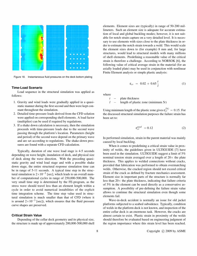
Figure 18. Instantaneous fluid pressures on the deck bottom plating
Time-Load ScenarioLoad sequence in the structural simulation was applied as
follows:
1. Gravity and wind loads were gradually applied in a quasi-static manner during the first second and then were kept con-stant throughout the simulation.
2. Detailed time-pressure loads derived from the CFD solutionwere applied on corresponding shell elements. A load factor(multiplier) can be used if required by regulations.
3. If a shake down calculation is necessary, then the simulationproceeds with time-pressure loads due to the second wavepassing through the platform’s location. Parameters (heightand period) of the second wave depend on the primary waveand are set according to regulations. The shake-down pres-sures are found with a separate CFD calculation.
Typically, duration of one wave load stage is 4-5 secondsdepending on wave height, inundation of deck, and physical sizeof deck along the wave direction. With the preceding quasi-static gravity and wind load stage and with a possible shakedown stage, the entire structural response simulation time canbe in range of 5-11 seconds. A typical time step in the struc-tural simulation is 2×10⁻⁵ [sec], which leads to an overall num-ber of computational cycles in range of 250,000-500,000. Thevery small time step is determined by the FE-program, as thestress wave should travel less than an element length within acycle in order to avoid numerical instabilities of the explicittime integration scheme. The time step value used in struc-tural simulation is much smaller than that of CFD (where itis around 2×10⁻³ [sec]), which ensures that the fluid pressurecurve shapes are preserved.
Critical Strain ValueDepending of the cellar deck geometry and its physical size,
the structure is made up of approximately 200,000-500,000 shell
elements. Element sizes are (typically) in range of 50-200 mil-limeters. Such an element size is adequate for accurate estima-tion of local and global buckling modes; however, it is not suit-able for notch strain capture on a very detailed level. It is neces-sary to use elements with sizes close to the plate thickness in or-der to estimate the notch strain towards a weld. This would scalethe element sizes down to (for example) 8 mm and, for largestructures, would lead to structural models with many millionsof shell elements. Predefining a reasonable value of the criticalstrain is therefore a challenge. According to NORSOK [6], thefollowing value of critical average strain in the material (for anaxially loaded plate) may be used in conjunction with nonlinearFinite Element analysis or simple plastic analysis:
εcr = 0.02 + 0.65tl
(1)
wheret − plate thicknessl − length of plastic zone (minimum 5t)
Using minimum length of the plastic zone gives ε(5t)cr = 0.15. For
the discussed structural simulation purposes the failure strain hasbeen set to:
εusedcr = 0.12 (2)
In performed simulation, strain in the parent material was mainlycaused by local buckling.
When it comes to predefining a critical strain value in prox-imity of welds, the guidelines given in ULTIGUIDE [7] havebeen used in the simulation. ULTIGUIDE suggest a limit of 5%nominal tension strain averaged over a length of 20× the platethickness. This applies to welded connections without cracks,provided that fabrication was performed to obtain overmatchingwelds. Otherwise, the cracked region should not exceed criticalstrain of the crack as defined by fracture mechanics assessment.Element size in important parts of the structure is normally farless than 20× the plate thickness, indicating that failure criteriaof 5% in the element can be used directly as a conservative as-sumption. A possibility of pre-defining the failure strain valueallows to continue the structural simulation even though someelements fail.
Wave-in-deck accident is normally an issue for old jacketplatforms subjected to a seabed subsidence. Typically, conditionof welds in the platform deck is not known, and inspection of theentire cellar deck is an enormous task. However, the cracks arealmost certain to exist. Plastic strain in proximity of the weldsshould therefore be evaluated based on engineering judgment ofthe region importance where this strain level has been reached.
8 Copyright c© 2009 by ASME

Areas considered to be vital for structural integrity of the plat-form should therefore be subjected to inspection for cracks ifplastic strain is found in these areas. If cracks are found, thenthe critical strain value can be defined by a fracture mechanicsassessment.
Large Displacements and Local Structural FailureVery large displacements or separation of larger parts of the
structure (after a local material failure) cannot be however ac-cepted. Firstly, the CFD simulation is performed on a rigid andfixed in space structure. A large displacement or separation ofa large structural part would influence the fluid flow pattern andthus the CFD-calculated pressures would be no longer valid. Andsecondly, the separated, falling parts may potentially damage thejacket structure.
A structural reinforcement needs to be designed and im-plemented in the FE-model, and the structural simulation mustbe re-run, perhaps several times, until an acceptable result isachieved. An evaluation of how the reinforcement influences thefluid flow must be done before the structural re-calculation is per-formed. If the added parts are flow-exposed and changes to thelocal flow pattern are likely, then a new CFD re-calculation mustbe done prior to the structural re-calculation.
Estimation of local notch stresses with use of shell elementscomparable in size to the plate thickness can be done by eitheranalysis of a refined cut-out of the global model or re-runningthe global model with appropriate local areas refined. The lateroption is preferred, as flexibility conditions of surrounding struc-ture will be much more accurate. Such analysis was performedon bottom plating of the example jacket, as it carried the loadmainly by a membrane action.
Results of the Structural Response SimulationA few pictures illustrate results from the structural response
simulation. The resultant stress (von Mises) distribution at sometime instant is shown in Fig. (19), where substantial deforma-tions of structural parts can be observed. Plastic strain utiliza-tion in the bottom plating is shown in Fig. (20), where colourshave been scaled to 5 % cut-off in order to improve legibility(red colour means a plastic strain of 5 % or more). Significantdeformations of bottom plates are visible again. An example offractured structural part is displayed in Fig. (21).
Structural Response Simulation, SummaryNumerical simulation of wave-in-deck structural response is
nowadays performed mostly with non-linear frame models. Re-sults from the approach presented in this paper indicate that usingof a frame model could lead to incorrect conclusions. A detailedmapping of the loading fluid pressure, which varies locally over
Figure 19. Part of the jacket’s deck, von Mises stress
Figure 20. Plastic strain utilization, 5% cut-off
the structural parts, has proven to be important for response cal-culations.
Failure modes are often found as twisting of the H-beams,as such beam is restrained against lateral deflection at top-flangedue to connection with deck plating. Frame model usually can-not reveal the torsion buckling. Frame model will also estimatecapacity of structural members as class 1 sections, independentof their actual slenderness. Typically, the frame-based simula-tion must therefore be supplemented by a large amount of hand-calculations in order to account for local failure modes.
CONCLUSIONS1. A solution methodology has been presented for a problem
of practical importance. Wave-in-deck loads for a jacketplatform have been predicted by a CFD simulation and non-linear transient response of the structure by a FE-code.
2. The applied CFD code ComFLOW uses the VOF methodto resolve fluid free surface movement. The employed CFD
9 Copyright c© 2009 by ASME

Figure 21. Fracture of an external beam
computational grid is of Cartesian type and is very easy togenerate.
3. A structure of arbitrarily complex shape, modelled asFE shell elements, can be submerged into the CartesianCFD computational grid. The two grids are independent.Fluid pressures obtained from the CFD simulation are di-rectly mapped onto the FE shell elements as time-pressurecurves. The structural response calculation is carried out byLS-DYNA FE-analysis code.
4. The pressure mapping procedure is to a large extent auto-mated. Further automation possibilities exist and will bepursued (i.e., assignment of shell element’s faces exposedto fluid flow).
5. It is noted that the CFD object is modelled as a rigid andfixed in space body. Body movement caused by the fluidflow and hydro-elasticity are not yet addressed. Improve-ments in this area are possible and feasibility of their imple-mentation will be explored.
6. An assessment procedure of a deck structure exposed tolarge dynamic loads has been developed. The method givesreasonable results. It is noted that the calculated strains mustbe further evaluated against actual status of welds (presenceof cracks and type of the weld) and against corrosion of thestructural parts.
REFERENCES[1] Kaplan, P., Murray, J.J., and Yu, W.C., 1995. “Theoretical
Analysis of Wave Impact Forces on Platform Deck Struc-tures”. In Proceedings, 14-th International OMAE Confer-ence, Copenhagen, Denmark.
[2] Iwanowski, B., Grigorian, H., and Scherf, I., 2002. “Sub-sidence of the Ekofisk Platforms: Wave in Deck ImpactStudy. Various Wave Models and Computational Meth-
ods”. In Proceedings, 21-st International OMAE Confer-ence, Oslo, Norway. Paper OMAE2002-28063.
[3] Brodtkorb, B., 2008. “Prediction of Wave-In-Deck Forceson Fixed Jacket-type Structures Based on CFD Calcula-tions”. In Proceedings, 27-th International OMAE Con-ference, Estoril, Portugal. Paper OMAE2008-57346.
[4] Brodtkorb, B., Nestegard, A., and Johansen, A., 2008.“Prediction of Increased Jacket Substructure Loads Due toWave-In-Deck Dffraction Based on CFD Calculations”. InProceedings, 27-th International OMAE Conference, Esto-ril, Portugal. Paper OMAE2008-57361.
[5] NORSOK Standard N-003. Actions and action effects. Edi-tion 2, September 2007.
[6] NORSOK Standard N-004. Design of steel structures.Rev. 2, October 2004.
[7] Det Norske Veritas, SINTEF and BOMEL, 1999. UL-TIGUIDE, Best Practice Guidelines for Use of Non-linearAnalysis Methods in Documentation of Ultimate LimitStates for Jacket Type Offshore Structures.
[8] Rudman, M., Cleary, P., Leontini, J., Sinnott, M., andPrakash, M., 2008. “Rogue Wave Impact on a Semi-submersible Offshore Platform”. In Proceedings, 27-th In-ternational OMAE Conference, Estoril, Portugal. PaperOMAE2008-57705.
[9] El Moctar, O., Schellin, T.E., and Peric, M., 2007. “WaveLoad and Structural Analysis for a Jack-up Platform inFreak Waves”. In Proceedings, 26-th International OMAEConference, San Diego, CA. Paper OMAE2007-29434.
[10] Kleefsman, K.M.T., 2005. “Water Impact Loading on Off-shore Structures - A Numerical Study”. PhD Thesis, Uni-versity of Groningen, The Netherlands, November.
[11] Kleefsman, K.M.T., Fekken, G., Veldman, A.E.P., Buchner,B., and Iwanowski, B., 2005. “A Volume-Of-Fluid BasedSimulation Method for Wave Impact Problems”. Journal ofComputational Physics, 206, pp. 363–393.
[12] Hirt, C.W., and Nichols, B.D., 1981. “Volume Of Fluid(VOF) Method for the Dynamics of Free Boundaries”.Journal of Computational Physics, 39, pp. 201–225.
[13] Wemmenhove, R., 2008. “Numerical Simulation of Two-Phase Flow in Offshore Environments”. PhD Thesis, Uni-versity of Groningen, The Netherlands, May.
[14] Wemmenhove, R., Luppes, R., Veldman, A.E.P., and Bun-nik, T., 2008. “Application of a VOF Method to ModelCompressible Two-Phase Flow in Sloshing Tanks”. In Pro-ceedings, 27-th International OMAE Conference, Estoril,Portugal. Paper OMAE2008-57254.
[15] Iwanowski, B., 2008. ComFLOW-2 JIP: Benchmarks ofthe ComFLOW Program. Technical Report TR-2008-0049,FORCE Technology Norway AS, Sandvika, Norway, Octo-ber.
[16] Livermore Software Technology Corporation (LSTC),2007. LS-DYNA Keyword User’s Manual, Version 971.
10 Copyright c© 2009 by ASME