
Watson-Marlow 520DuN IP66/NEMA 4X pumps Contentspdfs.wolflabs.co.uk/service/Watson-Marlow... ·...
105
Watson-Marlow 520DuN IP66/NEMA 4X User Manual 1 WATSON-MARLOW BREDEL MANUALS Watson-Marlow 520DuN IP66/NEMA 4X pumps m-520dun-4x-gb-05 Contents 1 Declaration of conformity 3 2 Declaration of incorporation 3 3 Five-year warranty 4 4 When you unpack your pump 5 5 Information for returning pumps 6 6 Peristaltic pumps: an overview 7 7 Safety notes 8 8 Pump specifications 10 8.1 Dimensions 15 9 Good pump installation practice 16 9.1 General recommendations 16 9.2 Do’s and do not’s 17 10 Connecting this product to a power supply 18 11 Start-up check list 21 12 Switching the pump on for the first time 21 13 Switching the pump on in subsequent power cycles (if not in auto-restart mode) 23 14 Manual operation 24 14.1 Keypad functions in manual mode 24 14.2 Keypad lock 27 14.3 Keypad beep 27 14.4 Manual operation and remote digital inputs and outputs 27 15 Main menu 28 15.1 Keypad functions in menu screens 28 15.2 Main menu entry 29 16 Pin-secure process protection 30 17 Calibrate 31 18 Setup 35 18.1 Trim 36 18.2 Analogue 37 18.3 Display 41 18.4 Pump number 42 18.5 Baud 42 18.6 Stop bits 43 18.7 Xon/Xoff 43 18.8 Flow units 44 18.9 Run time 45 18.10 Outputs 46 18.11 Remote stop 48 18.12 Auto-restart 50 18.13 Set maximum speed 51 18.14 Backlight 51 18.15 ROM 52 18.16 Language 52 18.17 Defaults 53 18.18 Beep 53 18.19 Security code 54 18.20 Exit 55 19 Pin-out details 55 20 MemoDose 56 20.1 Changing dosing speed 57 20.2 Footswitch operation with MemoDose 58 21 Exit 58 22 Automatic control wiring 59 22.1 520N module fitting 59 22.2 Wiring up 61 22.3 Speed: analogue input 64 22.4 Scaling: analogue input 65 22.5 Speed: analogue output 66 22.6 Tachometer frequency output 66 22.7 Run / stop input 67 22.8 Direction input 67 22.9 Auto / manual toggle 68 22.10 MemoDose input 68 22.11 Leak detection input 68 22.12 Outputs 1, 2, 3, 4 69 22.13 Supply voltages 69 22.14 RS485 input 70 23 Automatic control and operation 71 24 Network control and operation 74 24.1 RS485 command strings 76 25 Troubleshooting 77 25.1 Error codes 78 26 Drive maintenance 79 27 Drive spares 79 28 The 520R, 520R2 and 520RE pumpheads 80 28.1 Pumphead position, removal and replacement 81 29 520R, 520R2 and 520RE installation 83 29.1 Opening the guard 83
-
Upload
phamkhuong -
Category
Documents
-
view
241 -
download
3
Transcript of Watson-Marlow 520DuN IP66/NEMA 4X pumps Contentspdfs.wolflabs.co.uk/service/Watson-Marlow... ·...
Watson-Marlow 520DuN IP66/NEMA 4X User Manual 1
WATSON-MARLOW BREDEL MANUALS
Watson-Marlow 520DuNIP66/NEMA 4X pumps
m-520dun-4x-gb-05
Contents1 Declaration of conformity 32 Declaration of incorporation 33 Five-year warranty 44 When you unpack your pump 55 Information for returning pumps 66 Peristaltic pumps: an overview 77 Safety notes 88 Pump specifications 10
8.1 Dimensions 159 Good pump installation practice 16
9.1 General recommendations 169.2 Do’s and do not’s 17
10 Connecting this product to a power supply 18
11 Start-up check list 2112 Switching the pump on for the
first time 2113 Switching the pump on in
subsequent power cycles (if not in auto-restart mode) 23
14 Manual operation 2414.1 Keypad functions
in manual mode 2414.2 Keypad lock 2714.3 Keypad beep 2714.4 Manual operation
and remote digital inputs and outputs 27
15 Main menu 2815.1 Keypad functions in
menu screens 2815.2 Main menu entry 29
16 Pin-secure process protection 3017 Calibrate 3118 Setup 35
18.1 Trim 3618.2 Analogue 3718.3 Display 4118.4 Pump number 4218.5 Baud 4218.6 Stop bits 4318.7 Xon/Xoff 4318.8 Flow units 4418.9 Run time 4518.10 Outputs 4618.11 Remote stop 48
18.12 Auto-restart 5018.13 Set maximum speed 5118.14 Backlight 5118.15 ROM 5218.16 Language 5218.17 Defaults 5318.18 Beep 5318.19 Security code 5418.20 Exit 55
19 Pin-out details 5520 MemoDose 56
20.1 Changing dosing speed 5720.2 Footswitch operation
with MemoDose 5821 Exit 5822 Automatic control wiring 59
22.1 520N module fitting 5922.2 Wiring up 6122.3 Speed: analogue input 6422.4 Scaling: analogue input 6522.5 Speed: analogue output 6622.6 Tachometer frequency
output 6622.7 Run / stop input 6722.8 Direction input 6722.9 Auto / manual toggle 6822.10 MemoDose input 6822.11 Leak detection input 6822.12 Outputs 1, 2, 3, 4 6922.13 Supply voltages 6922.14 RS485 input 70
23 Automatic control and operation 71
24 Network control and operation 7424.1 RS485 command strings 76
25 Troubleshooting 7725.1 Error codes 78
26 Drive maintenance 7927 Drive spares 7928 The 520R, 520R2
and 520RE pumpheads 8028.1 Pumphead position,
removal and replacement 8129 520R, 520R2 and 520RE
installation 8329.1 Opening the guard 83
Watson-Marlow 520DuN IP66/NEMA 4X User Manual 2
29.2 520R and 520R2 tube loading 84
29.3 520RE: fitting the drain port 85
29.4 520RE Element loading 8629.5 520RE Element
connection 8830 520R, 520R2 and 520RE
maintenance 8931 520R, 520R2 and 520RE
rotor settings 90
32 Pumphead spares 9133 Flow rates 9234 Tubing and element
part numbers 10035 520 series pumping
accessories 10336 Trademarks 10437 Patient-connected applications 10438 Publication history 10439 Decontamination certificate 105
Watson-Marlow 520DuN IP66/NEMA 4X User Manual 3
1 Declaration of conformity
This declaration was issued for Watson-Marlow 720DuN pumps on May 1,2007. When this pump unit is used as a stand-alone pump it complieswith: Machinery Directive 2006/42/EC, EMC Directive 2004/108/EC.
This pump is ETL listed: ETL control number 3050250. Cert to CAN/CSAstd C22.2 No 61010-1. Conforms to UL std 61010A-1.
See 8 Pump specifications.
2 Declaration of incorporation
When this pump unit is to be installed into a machine or is to be assembled withother machines for installations, it must not be put into service until the relevantmachinery has been declared in conformity with the Machinery Directive2006/42/EC.
Responsible person: Christopher Gadsden, Managing Director, Watson-MarlowLimited, Falmouth, Cornwall TR11 4RU, England. Telephone +44 (0) 1326 370370Fax +44 (0) 1326 376009.
The information in this user guide is believed to be correct at the time of publica-tion. However, Watson-Marlow Limited accepts no liability for errors or omissions.Watson-Marlow Bredel has a policy of continuous product improvement, andreserves the right to alter specifications without notice. This manual is intended foruse only with the pump it was issued with. Earlier or later models may differ. Themost up-to-date manuals appear on the Watson-Marlow website: http://www.watson-marlow.com
Watson-Marlow 520DuN IP66/NEMA 4X User Manual 4
3 Five year warranty
520 cased pumps, 620 cased pumps and 720 cased pumps
For any 520, 620 or 720 cased pump purchased after 1 January 2007, Watson-Marlow Limited (“Watson-Marlow”) warrants, subject to the conditions and excep-tions below, through either Watson-Marlow, its subsidiaries, or its authorised distrib-utors, to repair or replace free of charge, any part of the product which fails withinfive years of the day of manufacture of the product. Such failure must have occurredbecause of defect in material or workmanship and not as a result of operation of theproduct other than in normal operation as defined in this pump manual.
Watson-Marlow shall not be liable for any loss, damage, or expense directly or indi-rectly related to or arising out of the use of its products, including damage or injurycaused to other products, machinery, buildings, or property, and Watson-Marlowshall not be liable for consequential damages, including, without limitation, lost prof-its, loss of time, inconvenience, loss of product being pumped, and loss of produc-tion. This warranty does not obligate Watson-Marlow to bear any costs of removal,installation, transportation, or other charges which may arise in connection with awarranty claim.
Conditions of and specific exceptions to the above warranty are:
Conditions� Products must be returned by pre-arrangement, carriage-paid, to Watson-
Marlow, or a Watson-Marlow approved service centre.� All repairs or modifications must have been made by Watson-Marlow Limited,
or a Watson-Marlow approved service centre or with the express permission ofWatson-Marlow.
� Warranties purporting to be on behalf of Watson-Marlow made by any person,including representatives of Watson-Marlow, its subsidiaries, or its distributors,which do not accord with the terms of this warranty shall not be binding uponWatson-Marlow unless expressly approved in writing by a Director or Managerof Watson-Marlow.
Exceptions� The warranty shall not apply to repairs or service necessitated by normal wear
and tear or for lack of reasonable and proper maintenance.� All tubing and pumping elements as consumable items are excluded.� Products which, in the judgment of Watson-Marlow, have been abused, mis-
used, or subjected to malicious or accidental damage or neglect are excluded.� Electrical surge as a cause of failure is excluded.� Chemical attack is excluded� All pumphead rollers are excluded.� The 620R family of pumpheads are excluded from all warranty when pumping
above 2 bar while above 165rpm.� Pumpheads from the 313/314 and the Microcassette ranges and any 701
extension pumpheads are excluded and retain their one-year standard pump-head warranty. The drive they are attached to is subject to the five-year war-ranty as set out here.
� Ancillaries such as leak detectors are excluded.
Watson-Marlow 520DuN IP66/NEMA 4X User Manual 5
4 When you unpack your pump
Unpack all parts carefully, retaining the packaging until you are sure all componentsare present and in good order. Check against the components supplied lists, below.
Packaging disposal
Dispose of packaging materials safely, and in accordance with regulations in yourarea. Pay particular attention to the expanded polystyrene shockproof shells. Theouter carton is made of corrugated cardboard and can be recycled.
Inspection
Check that all components are present. Inspect components for damage in transit.If anything is missing or damaged, contact your distributor immediately.
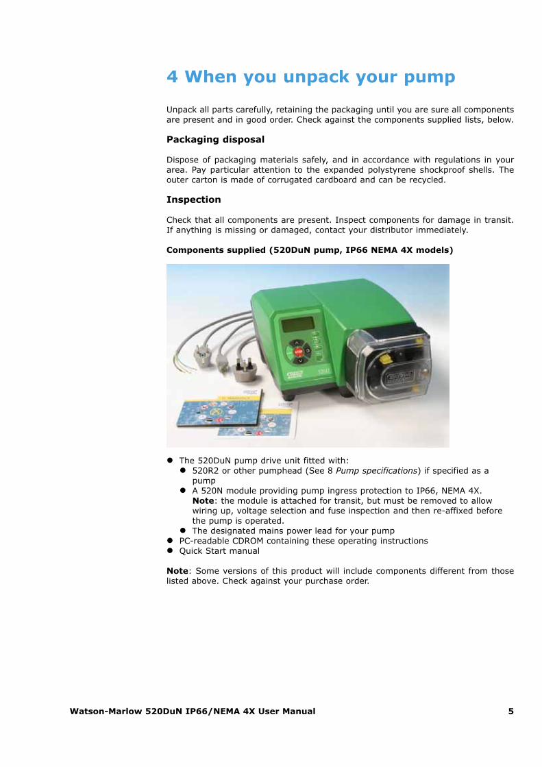
Components supplied (520DuN pump, IP66 NEMA 4X models)
� The 520DuN pump drive unit fitted with:� 520R2 or other pumphead (See 8 Pump specifications) if specified as a
pump� A 520N module providing pump ingress protection to IP66, NEMA 4X.
Note: the module is attached for transit, but must be removed to allowwiring up, voltage selection and fuse inspection and then re-affixed beforethe pump is operated.
� The designated mains power lead for your pump� PC-readable CDROM containing these operating instructions� Quick Start manual
Note: Some versions of this product will include components different from thoselisted above. Check against your purchase order.
Watson-Marlow 520DuN IP66/NEMA 4X User Manual 6
Storage
This product has an extended shelf life. However, care should be taken after storageto ensure that all parts function correctly. Users should be aware that the pump con-tains a battery with an unused life of seven years. Long-term storage is not recom-mended for peristaltic pump tubing. Please observe the storage recommendationsand use-by dates which apply to tubing you may wish to bring into service after storage.
5 Information for returning pumps
Equipment which has been contaminated with, or exposed to, body fluids, toxicchemicals or any other substance hazardous to health must be decontaminatedbefore it is returned to Watson-Marlow or its distributor.
A certificate included at the rear of these operating instructions, or signed state-ment, must be attached to the outside of the shipping carton. This certificate isrequired even if the pump is unused. See 39 Decontamination certificate.
If the pump has been used, the fluids that have been in contact with the pump andthe cleaning procedure must be specified along with a statement that the equipmenthas been decontaminated.
Watson-Marlow 520DuN IP66/NEMA 4X User Manual 7
6 Peristaltic pumps - an overview
Peristaltic pumps are the simplest possible pump, with no valves, seals or glands toclog or corrode. The fluid contacts only the bore of a tube, eliminating the risk of thepump contaminating the fluid, or the fluid contaminating the pump. Peristalticpumps can operate dry without risk.
How they work
A compressible tube is squeezed between a roller and a track on an arc of a circle,creating a seal at the point of contact. As the roller advances along the tube, theseal also advances. After the roller has passed, the tube returns to its original shape,creating a partial vacuum which is filled by fluid drawn from the inlet port.
Before the roller reaches the end of the track, a second roller compresses the tubeat the start of the track, isolating a packet of fluid between the compression points.As the first roller leaves the track, the second continues to advance, expelling thepacket of fluid through the pump’s discharge port. At the same time, a new partialvacuum is created behind the second roller into which more fluid is drawn from theinlet port.
Backflow and siphoning do not occur, and the pump effectively seals the tube whenit is inactive. No valves are needed.
The principle may be demonstrated by squeezing a soft tube between thumb andfinger and sliding it along: fluid is expelled from one end of the tube while more isdrawn in at the other.
Animal digestive tracts function in a similar way.
Suitable applications
Peristaltic pumping is ideal for most fluids, including viscous, shear-sensitive, corro-sive and abrasive fluids, and those containing suspended solids. They are especial-ly useful for pumping operations where hygiene is important.
Peristaltic pumps operate on the positive displacement principle. They are particu-larly suitable for metering, dosing and dispensing applications. Pumps are easy toinstall, simple to operate and inexpensive to maintain.
Watson-Marlow 520DuN IP66/NEMA 4X User Manual 8
7 Safety notes
In the interests of safety, this pump and the tubing selected should only be used bycompetent, suitably trained personnel after they have read and understood thismanual, and considered any hazard involved. If the pump is used in a manner notspecified by Watson-Marlow Ltd, the protection provided by the pump may beimpaired.
Any person who is involved in the installation or maintenance of this equipmentshould be fully competent to carry out the work. In the UK this person should alsobe familiar with the Health and Safety at Work Act 1974.
This symbol, used on the pump and in this manual,means: Caution, refer to accompanying documents.
This symbol, used on the pump and in this manual,means: Do not allow fingers to contact moving parts.
This symbol, used on the pump and in this manual,means: Recycle this product under the terms of the EUWaste Electrical and Electronic Equipment (WEEE)Directive.
Fundamental work with regard to lifting, trans-portation, installation, starting-up, maintenanceand repair should be perfor med by qualified per-
sonnel only. The unit must be isolated from mains powerwhile work is being carried out. The motor must be securedagainst accidental start-up.
There is a user-replaceable type T2,5A H 250Vfuse in the fuseholder in the centre of the switch-plate at the back of the pump. In some countries,
the mains power plug contains an additional replaceable fuse.There is a fuse on the interface card which self-resets afterfive seconds. There are no user-serviceable fuses or partsinside this pump.
Watson-Marlow 520DuN IP66/NEMA 4X User Manual 9
There are moving parts inside the pumphead. Before opening the tool-unlockable pumphead guard, ensure that the following safety directions are fol-lowed.� Ensure that the pump is isolated from the mains power.� Ensure that there is no pressure in the pipeline.� If a tube failure has occurred, ensure that any fluid in the pumphead has been
allowed to drain to a suitable vessel, container or drain.� Ensure that protective clothing and eye protection are worn if hazardous fluids
are pumped.� Primary operator protection from rotating parts of the pump is provided by the
pumphead safeguard. Note that safeguards differ, depending on the type ofpumphead. See the 28 pumphead section of this manual.
This pump must be used only for its intended purpose.
The pump must be accessible at all times to facilitate operation and maintenance.Access points must not be obstructed or blocked. Do not fit any devices to the driveunit other than those tested and approved by Watson-Marlow. Doing so could leadto injury to persons or damage to property for which no liability can be accepted.
If hazardous fluids are to be pumped, safety procedures specific to the particularfluid and application must be put in place to protect against injury to persons.
The exterior surfaces of the pump may get hot during operation. Do not take holdof the pump while it is running. Let it cool after use before handling it. The drive unitmust not be run without a pumphead fitted.
This product does not comply with the ATEX directive andmust not be used in explosive atmospheres.
Watson-Marlow 520DuN IP66/NEMA 4X User Manual 10
8 Pump specifications
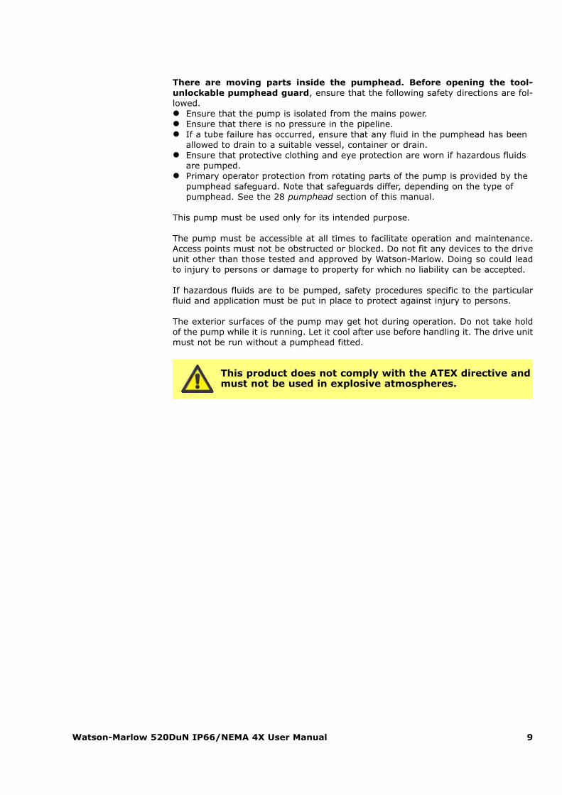
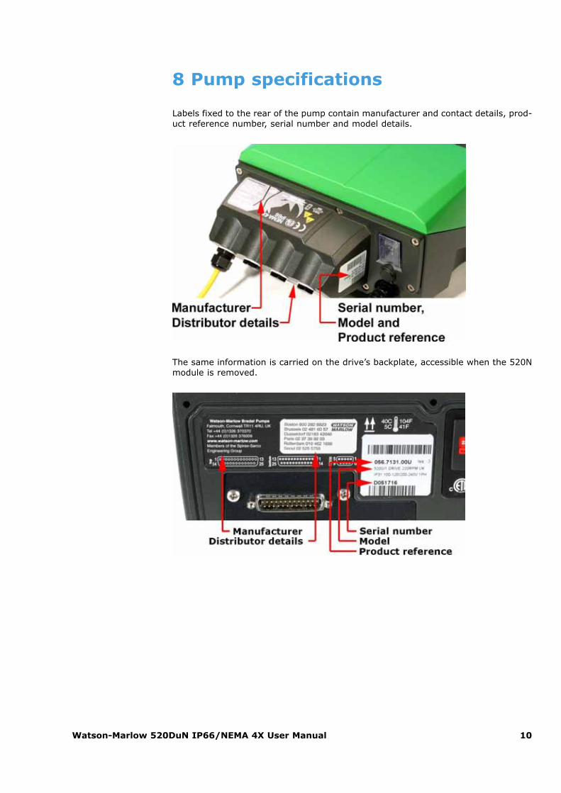
Labels fixed to the rear of the pump contain manufacturer and contact details, prod-uct reference number, serial number and model details.
The same information is carried on the drive’s backplate, accessible when the 520Nmodule is removed.
Watson-Marlow 520DuN IP66/NEMA 4X User Manual 11
520DuN, IP66 NEMA 4X model
This pump can be controlled from the keypad or remotely. It features:
Manual controlSpeed adjustment; run and stop; direction control; keypad scaling; “max” keyfor rapid priming.
Remote controlThe pump can be digitally controlled with a contact closure or logic input signalto operate the pump.
Analogue controlThe pump speed can be controlled through an analogue signal input in theranges 0-10V or 4-20mA. Scaling can be controlled similarly using Analoguesignal input 2.
RS485 serial communicationFull pump control from a PC or other controller with the ability to network up to32 pumps.
OutputsA 0-10V, 4-20mA or 0-1258Hz output signal provides feedback of the pumpspeed. There are four relay status outputs which can be configured in softwarefor a variety of pump parameters.
MemoDoseAllows precise repeat dosing. Stores in memory a pulse count from the motor.This count is repeated each time START is pressed to provide a single-shotdose.
CalibrationFull calibration with default figures for a range of pumpheads and tubes.Calibration dose facility.

Watson-Marlow 520DuN IP66/NEMA 4X User Manual 12
IP (Ingress Protection) and NEMA definitions
* 520N cased pumps are rated to NEMA 4X (indoor use) only.
IP NEMA
1st Digit 2nd Digit
3
Protected againstingress of solid objectswith a diameter ofmore than 2.5mm.Tools, wires etc with athickness of more than2.5mm are preventedfrom approach
1
Protection againstdripping water fallingvertically. No harmfuleffect must beproduced
2
Indoor use to provide adegree of protectionagainst limited amountsof falling water and dirt
5
Protected againstharmful dust deposits.Ingress of dust is nottotally prevented butthe dust must notenter in sufficientquantity to interferewith satisfactoryoperation of theequipment. Completeprotection againstcontact
5
Protection againstwater projected from anozzle against theequipment (enclosure)from any direction.There must be noharmful effect (waterjet)
12
Indoor use to provide adegree of protectionagainst dust, falling dirtand dripping, non-corrosive liquids
13
Indoor use to provide adegree of protectionagainst dust andspraying water, oil andnon-corrosive coolants
6
Protection againstingress of dust (dust-tight). Completeprotection againstcontact
6
Protection againstheavy seas or powerfulwater jets. Water mustnot enter theequipment (enclosure)in harmful quantities(splashing over)
4X
Indoor or outdoor* useto provide a degree ofprotection againstsplashing water, wind-blown dust and rain,hose-directed water;undamaged by theformation of ice on theenclosure. (Resistcorrosion: 200-hour saltspray)
Watson-Marlow 520DuN IP66/NEMA 4X User Manual 13
Pump specifications
Control range (turndown ratio) 0.1-360rpm (3,600:1)
Supply voltage/frequency 100-120V/200-240V 50/60Hz 1ph
Maximum voltage fluctuation
±10% of nominal voltage. A well regulated electrical mains supplyis required along with cable connections
to the best practice of noise immunity
Installation category (overvoltage category)
II
Power consumption 135VA
Full load current <0.6A at 230V; <1.25A at 115V
Eprom version Accessible through pump software
Enclosure rating IP66 to BS EN 60529;
NEMA 4X to NEMA 250 *
Pumphead options520R, 501RL, 313, 314, 505L,505BA, 505CA, 314MC, 318MC
Operating temperature range 5C to 40C, 41F to 104F
Storage temperature range -40C to 70C, -40F to 158F
Maximum altitude 2,000m, 6,560ft
Humidity (non-condensing)80% up to 31C, 88F, decreasing linearly
to 50% at 40C, 104F
Pollution degree 2
* Protect from prolonged UV exposure.
Note: 520 drive models are C ETL US listed. Cert to std CAN/CSA C22.2 No 1010-92. Conforms to std UL 61010A-1 April 30, 2002.
Note: 520 drive models have been tested in accordance with BS EN 61000-6-2:2001 (EN 61000-4-4) Fast Transient and Burst Tests to Industrial limits – ie: Level 3:2kV.
Watson-Marlow 520DuN IP66/NEMA 4X User Manual 14
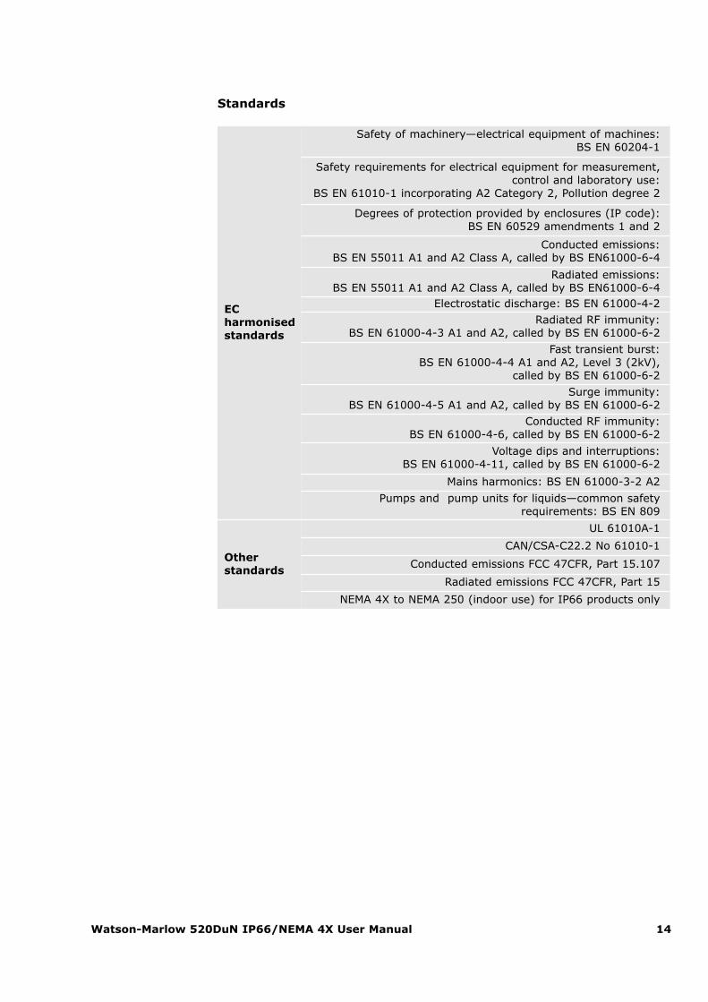
Standards
EC harmonisedstandards
Safety of machinery—electrical equipment of machines: BS EN 60204-1
Safety requirements for electrical equipment for measurement,control and laboratory use:
BS EN 61010-1 incorporating A2 Category 2, Pollution degree 2
Degrees of protection provided by enclosures (IP code):BS EN 60529 amendments 1 and 2
Conducted emissions:BS EN 55011 A1 and A2 Class A, called by BS EN61000-6-4
Radiated emissions:BS EN 55011 A1 and A2 Class A, called by BS EN61000-6-4
Electrostatic discharge: BS EN 61000-4-2
Radiated RF immunity:BS EN 61000-4-3 A1 and A2, called by BS EN 61000-6-2
Fast transient burst:BS EN 61000-4-4 A1 and A2, Level 3 (2kV),
called by BS EN 61000-6-2
Surge immunity:BS EN 61000-4-5 A1 and A2, called by BS EN 61000-6-2
Conducted RF immunity:BS EN 61000-4-6, called by BS EN 61000-6-2
Voltage dips and interruptions:BS EN 61000-4-11, called by BS EN 61000-6-2
Mains harmonics: BS EN 61000-3-2 A2
Pumps and pump units for liquids—common safety requirements: BS EN 809
Other standards
UL 61010A-1
CAN/CSA-C22.2 No 61010-1
Conducted emissions FCC 47CFR, Part 15.107
Radiated emissions FCC 47CFR, Part 15
NEMA 4X to NEMA 250 (indoor use) for IP66 products only
Watson-Marlow 520DuN IP66/NEMA 4X User Manual 15
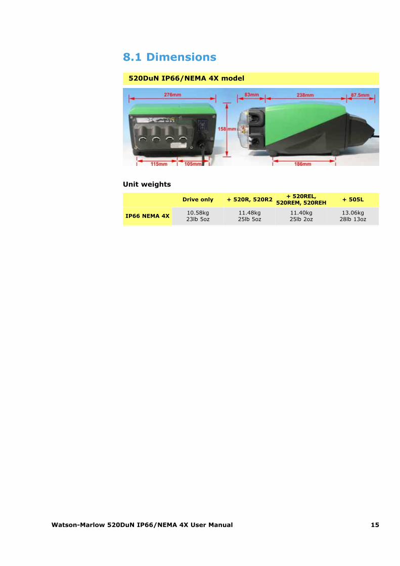
8.1 Dimensions
Unit weights
520DuN IP66/NEMA 4X model
Drive only + 520R, 520R2 + 520REL,520REM, 520REH + 505L
IP66 NEMA 4X 10.58kg23lb 5oz
11.48kg25lb 5oz
11.40kg25lb 2oz
13.06kg28lb 13oz
Watson-Marlow 520DuN IP66/NEMA 4X User Manual 16
9 Good pump installation practice
9.1 General recommendationsA correctly engineered installation will promote long tube life. Site the pump on aflat, horizontal, rigid surface, free from excessive vibration, to ensure correct lubri-cation of the gearbox. Allow a free flow of air around the pump to ensure that heatcan be dissipated. Ensure that the ambient temperature around the pump does notexceed 40C.
The STOP key on the keypad will always stop the pump. However, it is recommend-ed that a suitable local emergency stop device is fitted into the mains supply to thepump.
Do not stack pumps more than three high. When pumps are stacked, ensure thatthe ambient temperature around all the pumps in the stack does not exceed 40C.
The pump may be set up so that the direction of rotor rotation is clockwise or count-er-clockwise, whichever is convenient. Please note, however, that for the 520R and501RL pumpheads tube life will be greater if the rotor rotates clockwise; and thatperformance against pressure will be maximised if the rotor rotates counter-clock-wise. To achieve 4 bar and 7 bar pressures using a 520RE pump and the appropri-ate rotor and element, the pump must rotate counter-clockwise.
Peristaltic pumps are self-priming and self-sealing against backflow. No valves arerequired in inlet or discharge lines, except as described below. Valves in the processflow must be opened before the pump operates. Users are advised to fit a pressurerelief device between the pump and any valve on the discharge side of the pump toprotect against damage caused by accidental operation with the discharge valveclosed. Users of 520RE pumps at pressures up to 4 bar and 7 bar are advised to fita non-return valve between the pump and the discharge pipework to avoid the sud-den release of pressurised fluid in the unlikely event of element failure.
9.2 Do’s and do not’sDo not build a pump into a tight location without adequate airflow around the pump.
Do ensure that when the 520N watertight module is fitted the seals are intact andproperly located.
Do ensure that the holes for cable glands are properly sealed to maintain theIP66 /NEMA 4X rating.
Watson-Marlow 520DuN IP66/NEMA 4X User Manual 17
Do not strap the control and mains power cables together.
Do keep delivery and suction tubes as short and direct as possible - though ideallynot shorter than 1m - and follow the straightest route. Use bends of large radius: atleast four times the tubing diameter. Ensure that connecting pipework and fittingsare suitably rated to handle the predicted pipeline pressure. Avoid pipe reducers andlengths of smaller bore tubing than the pumphead section, particularly in pipelineson the suction side. Any valves in the pipeline (not usually needed with a self-prim-ing peristaltic pump) must not restrict the flow. Any valves in the flow line must beopen when the pump is running.
Do use suction and delivery pipes equal to or larger than the bore of the tube in thepumphead. When pumping viscous fluids use pipe runs with a bore several timeslarger than the pump tube.
Do ensure that on longer tube runs at least 1m of smooth bore flexible tubing is con-nected to the inlet and discharge port of the pumphead to help to minimize impulselosses and pulsation in the pipeline. This is especially important with viscous fluidsand when connecting to rigid pipework.
Do site the pump at or just below the level of the fluid to be pumped if possible.This will ensure flooded suction and maximum pumping efficiency.
Do keep the pumphead track and all moving parts clean and free from contamina-tion and debris.
Do run at slow speed when pumping viscous fluids. When using the 520R pumphead,a 6.4mm or 4.8mm bore tube with a 2.4mm wall will give best results. Tube smallerthan this will generate a high friction loss, so reducing the flow. Tube with a largerbore may not have sufficient strength to restitute fully. Flooded suction will enhancepumping performance in all cases, particularly for materials of a viscous nature.
Do recalibrate after changing pump tubes, fluid, or any connecting pipework. It isalso recommended that the pump is recalibrated periodically to maintain accuracy.
IP66 / NEMA 4X models may be hosed down, but should not be immersed. Protectfrom prolonged UV exposure.
When using Marprene or Bioprene continuous tubing, do re-tension the tubeafter the first 30 minutes of running.
Tube selection: The chemical compatibility lists published in Watson-Marlow pub-lications are guides. If in doubt about the compatibility of a tube material and theduty fluid, request a Watson-Marlow tube sample card for immersion trials.
Watson-Marlow 520DuN IP66/NEMA 4X User Manual 18
10 Connecting this product to a power supply
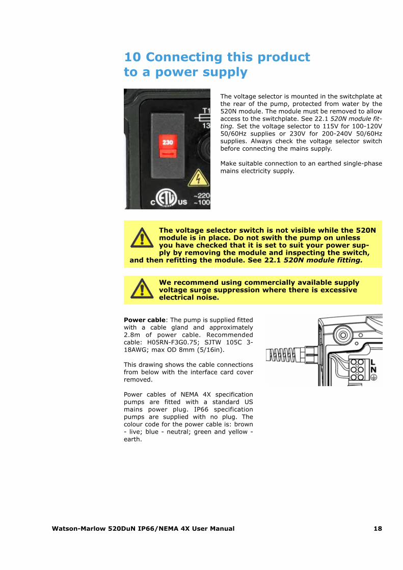
The voltage selector is mounted in the switchplate atthe rear of the pump, protected from water by the520N module. The module must be removed to allowaccess to the switchplate. See 22.1 520N module fit-ting. Set the voltage selector to 115V for 100-120V50/60Hz supplies or 230V for 200-240V 50/60Hzsupplies. Always check the voltage selector switchbefore connecting the mains supply.
Make suitable connection to an earthed single-phasemains electricity supply.
The voltage selector switch is not visible while the 520Nmodule is in place. Do not swith the pump on unlessyou have checked that it is set to suit your power sup-ply by removing the module and inspecting the switch,
and then refitting the module. See 22.1 520N module fitting.
We recommend using commercially available supplyvoltage surge suppression where there is excessiveelectrical noise.
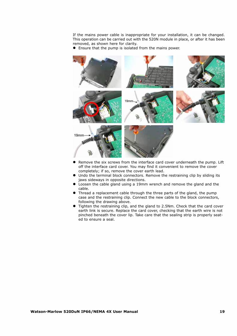
Power cable: The pump is supplied fittedwith a cable gland and approximately2.8m of power cable. Recommendedcable: H05RN-F3G0.75; SJTW 105C 3-18AWG; max OD 8mm (5/16in).
This drawing shows the cable connectionsfrom below with the interface card coverremoved.
Power cables of NEMA 4X specificationpumps are fitted with a standard USmains power plug. IP66 specificationpumps are supplied with no plug. Thecolour code for the power cable is: brown- live; blue - neutral; green and yellow -earth.
Watson-Marlow 520DuN IP66/NEMA 4X User Manual 19
If the mains power cable is inappropriate for your installation, it can be changed.This operation can be carried out with the 520N module in place, or after it has beenremoved, as shown here for clarity.� Ensure that the pump is isolated from the mains power.
� Remove the six screws from the interface card cover underneath the pump. Liftoff the interface card cover. You may find it convenient to remove the covercompletely; if so, remove the cover earth lead.
� Undo the terminal block connectors. Remove the restraining clip by sliding itsjaws sideways in opposite directions.
� Loosen the cable gland using a 19mm wrench and remove the gland and thecable.
� Thread a replacement cable through the three parts of the gland, the pumpcase and the restraining clip. Connect the new cable to the block connectors,following the drawing above.
� Tighten the restraining clip, and the gland to 2.5Nm. Check that the card coverearth link is secure. Replace the card cover, checking that the earth wire is notpinched beneath the cover lip. Take care that the sealing strip is properly seat-ed to ensure a seal.
Watson-Marlow 520DuN IP66/NEMA 4X User Manual 20
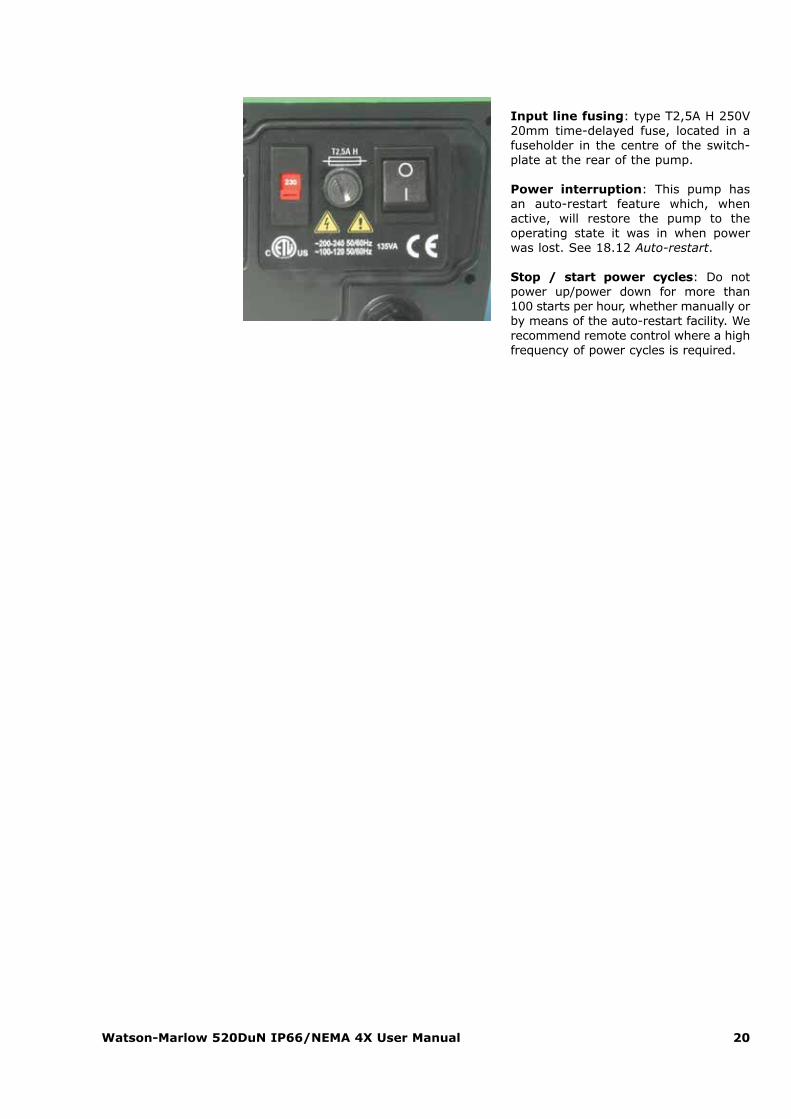
Input line fusing: type T2,5A H 250V20mm time-delayed fuse, located in afuseholder in the centre of the switch-plate at the rear of the pump.
Power interruption: This pump hasan auto-restart feature which, whenactive, will restore the pump to theoperating state it was in when powerwas lost. See 18.12 Auto-restart.
Stop / start power cycles: Do notpower up/power down for more than100 starts per hour, whether manually orby means of the auto-restart facility. Werecommend remote control where a highfrequency of power cycles is required.
Watson-Marlow 520DuN IP66/NEMA 4X User Manual 21
11 Start-up check list
Note: See also 29.2 Tube loading.� Ensure that proper connections are achieved between the pump tube and suc-
tion and discharge piping.� Ensure proper connection has been made to a suitable power supply.� Ensure that the recommendations in the section on 9 Good pump installation
practice are followed.
12 Switching the pump on for thefirst time
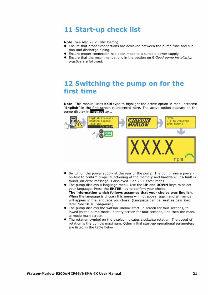
Note: This manual uses bold type to highlight the active option in menu screens:“English” in the first screen represented here. The active option appears on thepump display in inverse text.
� Switch on the power supply at the rear of the pump. The pump runs a power-on test to confirm proper functioning of the memory and hardware. If a fault isfound, an error message is displayed. See 25.1 Error codes.
� The pump displays a language menu. Use the UP and DOWN keys to selectyour language. Press the ENTER key to confirm your choice. The information which follows assumes that your choice was English.When the language is chosen this menu will not appear again and all menuswill appear in the language you chose. (Language can be reset as describedlater. See 18.16 Language.)
� The pump displays the Watson-Marlow start-up screen for four seconds, fol-lowed by the pump model identity screen for four seconds, and then the manu-al mode main screen.
� The rotation symbol on the display indicates clockwise rotation. The speed ofrotation is the pump’s maximum. Other initial start-up operational parametersare listed in the table below.
Watson-Marlow 520DuN IP66/NEMA 4X User Manual 22
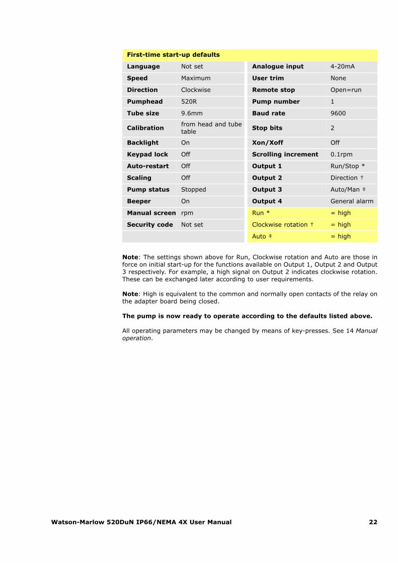
First-time start-up defaults
Language Not set Analogue input 4-20mA
Speed Maximum User trim None
Direction Clockwise Remote stop Open=run
Pumphead 520R Pump number 1
Tube size 9.6mm Baud rate 9600
Calibrationfrom head and tubetable
Stop bits 2
Backlight On Xon/Xoff Off
Keypad lock Off Scrolling increment 0.1rpm
Auto-restart Off Output 1 Run/Stop *
Scaling Off Output 2 Direction †
Pump status Stopped Output 3 Auto/Man ‡
Beeper On Output 4 General alarm
Manual screen rpm Run * = high
Security code Not set Clockwise rotation † = high
Auto ‡ = high
Note: The settings shown above for Run, Clockwise rotation and Auto are those inforce on initial start-up for the functions available on Output 1, Output 2 and Output3 respectively. For example, a high signal on Output 2 indicates clockwise rotation.These can be exchanged later according to user requirements.
Note: High is equivalent to the common and normally open contacts of the relay onthe adapter board being closed.
The pump is now ready to operate according to the defaults listed above.
All operating parameters may be changed by means of key-presses. See 14 Manualoperation.
Watson-Marlow 520DuN IP66/NEMA 4X User Manual 23
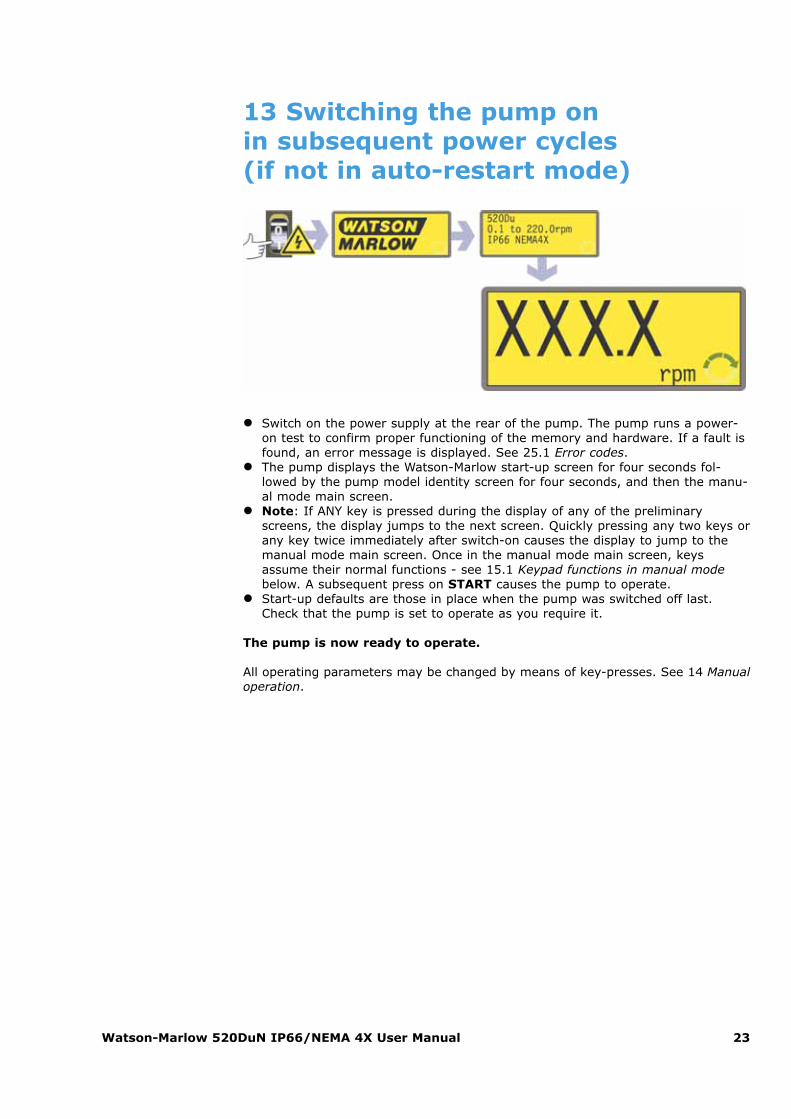
13 Switching the pump on in subsequent power cycles (if not in auto-restart mode)
� Switch on the power supply at the rear of the pump. The pump runs a power-on test to confirm proper functioning of the memory and hardware. If a fault isfound, an error message is displayed. See 25.1 Error codes.
� The pump displays the Watson-Marlow start-up screen for four seconds fol-lowed by the pump model identity screen for four seconds, and then the manu-al mode main screen.
� Note: If ANY key is pressed during the display of any of the preliminaryscreens, the display jumps to the next screen. Quickly pressing any two keys orany key twice immediately after switch-on causes the display to jump to themanual mode main screen. Once in the manual mode main screen, keysassume their normal functions - see 15.1 Keypad functions in manual modebelow. A subsequent press on START causes the pump to operate.
� Start-up defaults are those in place when the pump was switched off last.Check that the pump is set to operate as you require it.
The pump is now ready to operate.
All operating parameters may be changed by means of key-presses. See 14 Manualoperation.
Watson-Marlow 520DuN IP66/NEMA 4X User Manual 24
14 Manual operation
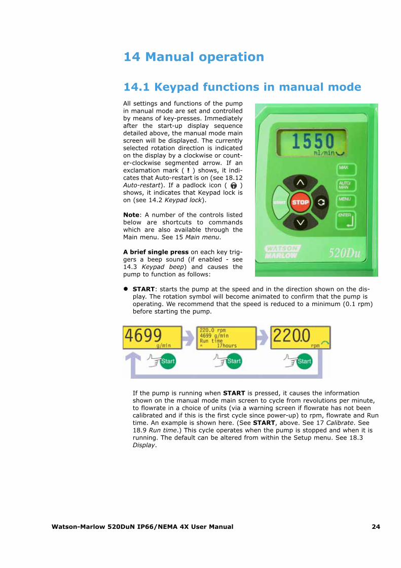
14.1 Keypad functions in manual modeAll settings and functions of the pumpin manual mode are set and controlledby means of key-presses. Immediatelyafter the start-up display sequencedetailed above, the manual mode mainscreen will be displayed. The currentlyselected rotation direction is indicatedon the display by a clockwise or count-er-clockwise segmented arrow. If anexclamation mark ( ! ) shows, it indi-cates that Auto-restart is on (see 18.12Auto-restart). If a padlock icon ( )shows, it indicates that Keypad lock ison (see 14.2 Keypad lock).
Note: A number of the controls listedbelow are shortcuts to commandswhich are also available through theMain menu. See 15 Main menu.
A brief single press on each key trig-gers a beep sound (if enabled - see14.3 Keypad beep) and causes thepump to function as follows:
� START: starts the pump at the speed and in the direction shown on the dis-play. The rotation symbol will become animated to confirm that the pump isoperating. We recommend that the speed is reduced to a minimum (0.1 rpm)before starting the pump.
If the pump is running when START is pressed, it causes the informationshown on the manual mode main screen to cycle from revolutions per minute,to flowrate in a choice of units (via a warning screen if flowrate has not beencalibrated and if this is the first cycle since power-up) to rpm, flowrate and Runtime. An example is shown here. (See START, above. See 17 Calibrate. See18.9 Run time.) This cycle operates when the pump is stopped and when it isrunning. The default can be altered from within the Setup menu. See 18.3Display.
Watson-Marlow 520DuN IP66/NEMA 4X User Manual 25
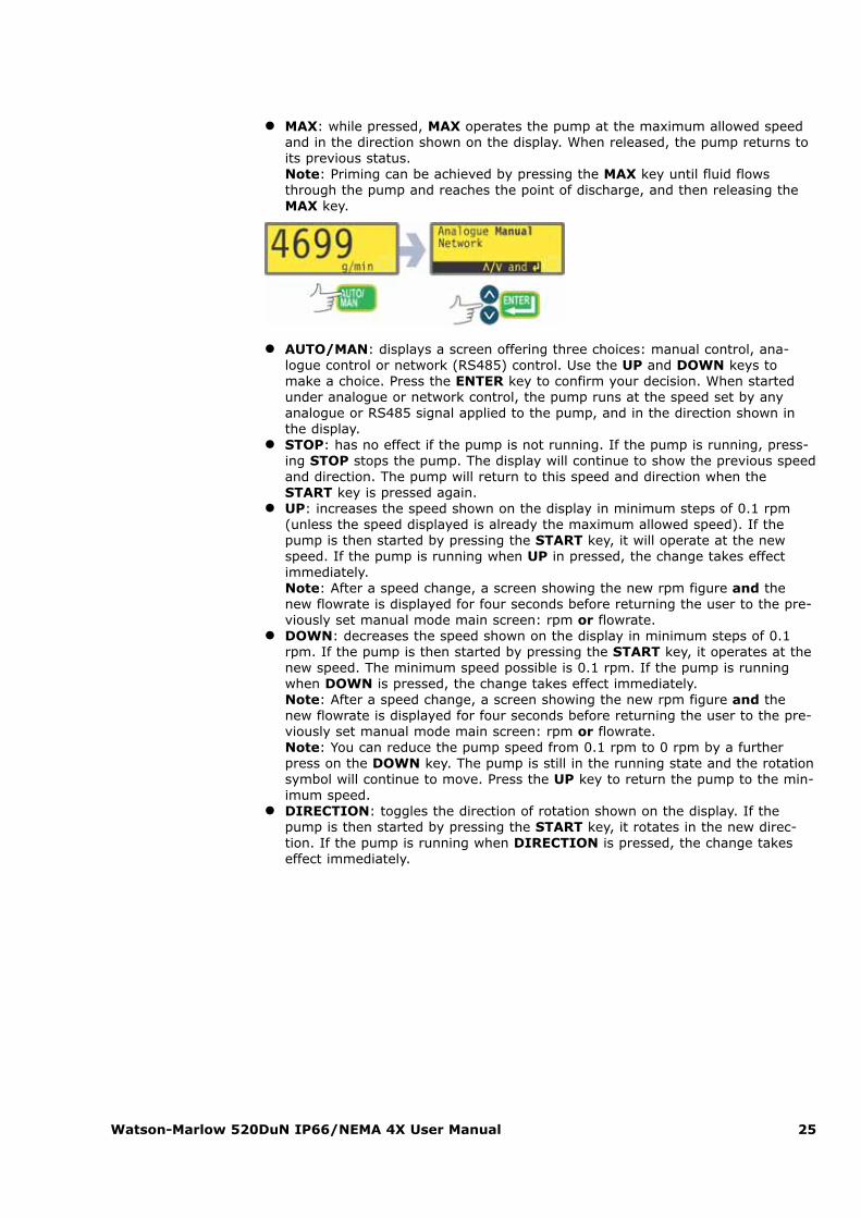
� MAX: while pressed, MAX operates the pump at the maximum allowed speedand in the direction shown on the display. When released, the pump returns toits previous status.Note: Priming can be achieved by pressing the MAX key until fluid flowsthrough the pump and reaches the point of discharge, and then releasing theMAX key.
� AUTO/MAN: displays a screen offering three choices: manual control, ana-logue control or network (RS485) control. Use the UP and DOWN keys tomake a choice. Press the ENTER key to confirm your decision. When startedunder analogue or network control, the pump runs at the speed set by anyanalogue or RS485 signal applied to the pump, and in the direction shown inthe display.
� STOP: has no effect if the pump is not running. If the pump is running, press-ing STOP stops the pump. The display will continue to show the previous speedand direction. The pump will return to this speed and direction when theSTART key is pressed again.
� UP: increases the speed shown on the display in minimum steps of 0.1 rpm(unless the speed displayed is already the maximum allowed speed). If thepump is then started by pressing the START key, it will operate at the newspeed. If the pump is running when UP in pressed, the change takes effectimmediately.Note: After a speed change, a screen showing the new rpm figure and thenew flowrate is displayed for four seconds before returning the user to the pre-viously set manual mode main screen: rpm or flowrate.
� DOWN: decreases the speed shown on the display in minimum steps of 0.1rpm. If the pump is then started by pressing the START key, it operates at thenew speed. The minimum speed possible is 0.1 rpm. If the pump is runningwhen DOWN is pressed, the change takes effect immediately.Note: After a speed change, a screen showing the new rpm figure and thenew flowrate is displayed for four seconds before returning the user to the pre-viously set manual mode main screen: rpm or flowrate.Note: You can reduce the pump speed from 0.1 rpm to 0 rpm by a furtherpress on the DOWN key. The pump is still in the running state and the rotationsymbol will continue to move. Press the UP key to return the pump to the min-imum speed.
� DIRECTION: toggles the direction of rotation shown on the display. If thepump is then started by pressing the START key, it rotates in the new direc-tion. If the pump is running when DIRECTION is pressed, the change takeseffect immediately.
Watson-Marlow 520DuN IP66/NEMA 4X User Manual 26
� ENTER: cycles the information shown on the manual mode main screen fromrevolutions per minute, to flowrate in a choice of units (via a warning screen ifflowrate has not been calibrated) to rpm, flowrate and Run time. (See START,above. See 17 Calibrate. See 18.9 Run time.) This cycle operates when thepump is stopped and when it is running. The default can be altered from withinthe Setup menu. See 18.3 Display.
� MENU: causes the main menu to be displayed, from which all aspects of pumpsetup can be controlled. See 15 Main menu.
Keypress combinations cause the pump to function as follows:� UP and DIRECTION on power-up: toggles the keypad beep on and off.� START on power-up: switches on the Auto-restart facility. See 18.12 Auto-
restart.� STOP on power-up: switches off the Auto-restart facility. See 18.12 Auto-
restart.� STOP and DIRECTION on power-up: allows the user to press UP and DOWN
keys to toggle the sense of remote run / stop control between open=stop andopen=run.
� STOP and UP while the pump is stopped: turns the display backlight on.� STOP and DOWN while the pump is stopped: turns the display backlight off.� MAX and UP: sets the pump to maximum allowed speed.� MAX and DOWN: sets the pump to minimum speed.� DIRECTION and DOWN: interrupts the display to show the pump’s ROM ver-
sion for four seconds.� START pressed and held for two seconds: toggles the keypad lock on and off.
Only the START and STOP keys are active when keypad lock is on. The pad-lock icon is displayed.
� STOP pressed and held for two seconds: toggles the keypad lock on and off.Only the START and STOP keys are active when keypad lock is on. The pad-lock icon is displayed.
� STOP STOP within half a second: shortcut entry to MemoDose; when inMemoDose, shortcut return to manual mode main screen. See 20 MemoDose.
Note: The maximum allowed speed of the drive defaults to 220 rpm. It is possibleto set this limit at any speed up to this value. See 18.13 Set maximum speed.
Watson-Marlow 520DuN IP66/NEMA 4X User Manual 27
14.2 Keypad lockThe keypad can be locked to prevent changes to pump speed or other settings, andmake it possible only to start or stop the pump. The padlock symbol shows on thedisplay.� While the pump is running, hold down the START key for two seconds. The
padlock symbol shows and only the START and STOP keys function.� The keypad may also be locked while the pump is stopped. Hold down the
STOP key for two seconds. The padlock symbol shows and only the STARTand STOP keys function.
� To unlock the keypad while the pump is running hold down the START key fortwo seconds. The padlock symbol is removed. If the pump is stopped holddown the STOP key until the padlock symbol is removed.
14.3 Keypad beepThe pump keypad can operate silently or indicate a positive key-press with a beepsound.� To toggle the sound on and off, stop the pump. Turn off the mains power switch
at the rear of the pump.� Depress the UP and DIRECTION keys while switching on the mains power
switch at the rear of the pump.
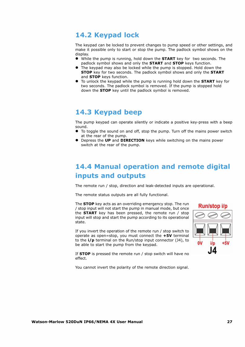
14.4 Manual operation and remote digitalinputs and outputsThe remote run / stop, direction and leak-detected inputs are operational.
The remote status outputs are all fully functional.
The STOP key acts as an overriding emergency stop. The run/ stop input will not start the pump in manual mode, but oncethe START key has been pressed, the remote run / stopinput will stop and start the pump according to its operationalstate.
If you invert the operation of the remote run / stop switch tooperate as open=stop, you must connect the +5V terminalto the i/p terminal on the Run/stop input connector (J4), tobe able to start the pump from the keypad.
If STOP is pressed the remote run / stop switch will have noeffect.
You cannot invert the polarity of the remote direction signal.
Watson-Marlow 520DuN IP66/NEMA 4X User Manual 28
15 Main menu
15.1 Keypad functions in menu screensIn addition to their functions in otheroperations, the following keys havespecific actions in menu screens:� STOP: In general, STOP functions
as a “go back” key, taking the userup one menu level without makinga change.
� UP: The UP key is used in menuitem selection: it moves a highlightup the menu. When a numericalentry screen is displayed, pressingUP increases the number dis-played.
� DOWN: The DOWN key is used inmenu item selection: it moves ahighlight down a menu. When anumerical entry screen is dis-played, pressing DOWN decreasesthe number displayed.
� ENTER: The ENTER key functionsin a similar way to the “enter” keyof a personal computer: it confirmskey-presses made immediatelybefore. In menu item selection, ittriggers the action or displayselected from a menu using the UP and DOWN keys.
Note: Confirmation screens are displayed for 4 seconds. While they are displayed,a single press on any key removes them.
Watson-Marlow 520DuN IP66/NEMA 4X User Manual 29
15.2 Main menu entryThe MENU key displays the main menu. It operates at any point in the pump’s activ-ity except where error screens are displayed, or screens where UP and DOWN keysare used to enter values.
The main menu offers five options: Calibrate, Setup, Pin out details, MemoDoseand Exit. Use the UP and DOWN keys to make a choice. Press the ENTER key toconfirm your decision.
Calibrate
Calibrate allows the user to calibrate the pump with default figures for a range ofpumpheads and tubes, as well as to refine the flowrate figures with a calibrationdose facility.
Setup
Setup allows the user to set the pump’s operating parameters under 20 headings:Trim, Analogue, Display, Pump number, Baud, Stop bits, Xon/Xoff, Flowunits, Run time, Outputs, Remote stop, Auto-restart, Set max speed,Backlight, ROM, Language, Defaults, Beep, Security and Exit.
Pin out details
Pin out information is not relevant to the 520DuN IP66/NEMA 4X pump. SelectingPin out details causes the pump to display a warning screen and redisplay the mainmenu.
MemoDose
The MemoDose facility is used to remember the number of revolutions needed to dis-pense a set volume of fluid, and cause the pump to dispense that volume repeatedly.
Exit
If Exit is selected, the pump returns to its last manual state with the pump stopped.

Watson-Marlow 520DuN IP66/NEMA 4X User Manual 30
16 PIN-secure process protectionThe 520DuN and 520Du feature PIN-secure process protection. This allows thepump to be configured to suit the application, and for the setup to be protectedby two levels of PIN code. See 18.19 Security code setup.
* When the keypad is locked, MemoDose is available via its access shortcut:press STOP twice; it is not available through the menu structure.
The main code allows changes to Calibrate, Setup, Direction and Keypadlock.
The secondary (User) code permits Calibrate, Direction change and Keypadlock but bars Setup change.
If either code is used in conjunction with Keypad lock, all keys are disabledexcept STOP and START.
To activate and set a security code, see 18.19 Security code setup.
If the main code is lost or forgotten: The Setup main security code can bebypassed by entering a special key sequence; all codes can then be cancelledand reset. Contact Watson-Marlow or your distributor for details.
Menu option or keypress
With Main code set
With User code set
Code set andkeypad locked
Menu Available Available Not availableCalibrate Available Available Not available
Accept Available Available Not available
Change Main PINneeded
Main PIN or User PIN needed Not available
Setup Main PINneeded
Main PIN needed;User PIN invalid Not available
MemoDose Available Available Available*
Pin out details Available Available Not available
Max Available Available Not available
Dir Main PINneeded
Main PIN or User PIN needed Not available
Auto / Man Available Available Not available
Up Available Available Not available
Down Available Available Not available
Max and Up Available Available Not available
Max and Down Available Available Not available
Start Available Available Available
Stop Available Available Available
Enter Available Available Not available
Keypad lock Main PINneeded
Main PIN or User PIN needed
Main PIN or User PIN needed
Auto-restart Available Available Available
Watson-Marlow 520DuN IP66/NEMA 4X User Manual 31
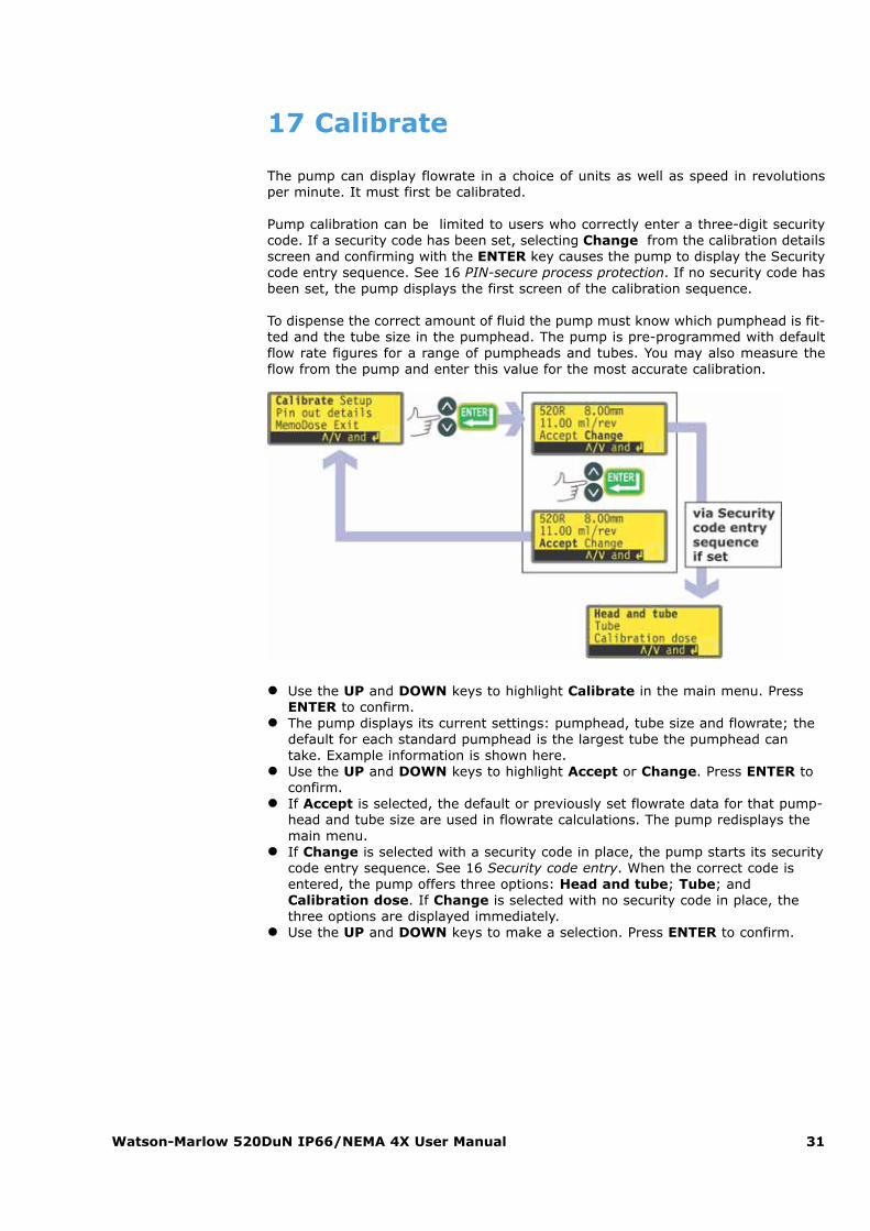
17 Calibrate
The pump can display flowrate in a choice of units as well as speed in revolutionsper minute. It must first be calibrated.
Pump calibration can be limited to users who correctly enter a three-digit securitycode. If a security code has been set, selecting Change from the calibration detailsscreen and confirming with the ENTER key causes the pump to display the Securitycode entry sequence. See 16 PIN-secure process protection. If no security code hasbeen set, the pump displays the first screen of the calibration sequence.
To dispense the correct amount of fluid the pump must know which pumphead is fit-ted and the tube size in the pumphead. The pump is pre-programmed with defaultflow rate figures for a range of pumpheads and tubes. You may also measure theflow from the pump and enter this value for the most accurate calibration.
� Use the UP and DOWN keys to highlight Calibrate in the main menu. PressENTER to confirm.
� The pump displays its current settings: pumphead, tube size and flowrate; thedefault for each standard pumphead is the largest tube the pumphead cantake. Example information is shown here.
� Use the UP and DOWN keys to highlight Accept or Change. Press ENTER toconfirm.
� If Accept is selected, the default or previously set flowrate data for that pump-head and tube size are used in flowrate calculations. The pump redisplays themain menu.
� If Change is selected with a security code in place, the pump starts its securitycode entry sequence. See 16 Security code entry. When the correct code isentered, the pump offers three options: Head and tube; Tube; andCalibration dose. If Change is selected with no security code in place, thethree options are displayed immediately.
� Use the UP and DOWN keys to make a selection. Press ENTER to confirm.
Watson-Marlow 520DuN IP66/NEMA 4X User Manual 32
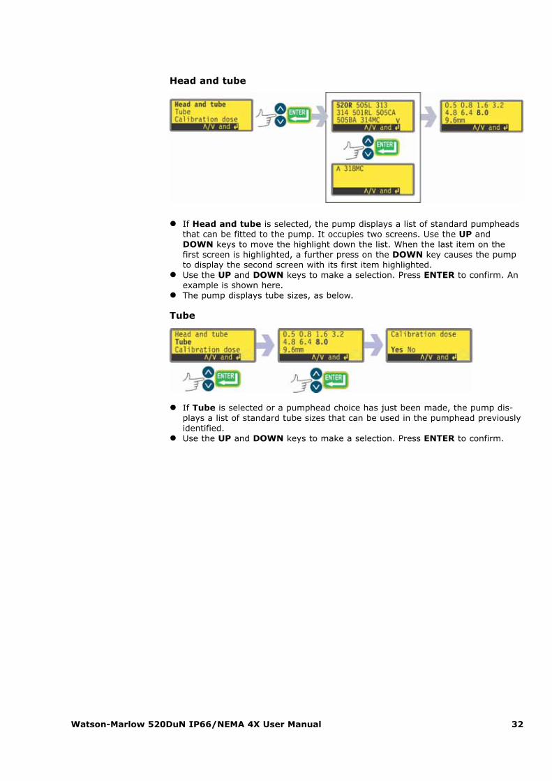
Head and tube
� If Head and tube is selected, the pump displays a list of standard pumpheadsthat can be fitted to the pump. It occupies two screens. Use the UP andDOWN keys to move the highlight down the list. When the last item on thefirst screen is highlighted, a further press on the DOWN key causes the pumpto display the second screen with its first item highlighted.
� Use the UP and DOWN keys to make a selection. Press ENTER to confirm. Anexample is shown here.
� The pump displays tube sizes, as below.
Tube
� If Tube is selected or a pumphead choice has just been made, the pump dis-plays a list of standard tube sizes that can be used in the pumphead previouslyidentified.
� Use the UP and DOWN keys to make a selection. Press ENTER to confirm.
Watson-Marlow 520DuN IP66/NEMA 4X User Manual 33
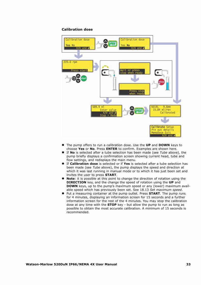
Calibration dose
� The pump offers to run a calibration dose. Use the UP and DOWN keys tochoose Yes or No. Press ENTER to confirm. Examples are shown here.
� If No is selected after a tube selection has been made (see Tube above), thepump briefly displays a confirmation screen showing current head, tube andflow settings, and redisplays the main menu.
� If Calibration dose is selected or if Yes is selected after a tube selection hasbeen made (see Tube above), the pump displays the speed and direction atwhich it was last running in manual mode or to which it has just been set andinvites the user to press START.
� Note: it is possible at this point to change the direction of rotation using theDIRECTION key, and the change the speed of rotation using the UP andDOWN keys, up to the pump’s maximum speed or any (lower) maximum avail-able speed which has previously been set. See 18.13 Set maximum speed.
� Put a measuring container at the pump outlet. Press START. The pump runsfor 4 minutes, displaying an information screen for 15 seconds and a furtherinformation screen for the rest of the 4 minutes. You may stop the calibrationdose at any time with the STOP key - but allow the pump to run as long aspossible to obtain the most accurate calibration. A minimum of 15 seconds isrecommended.
Watson-Marlow 520DuN IP66/NEMA 4X User Manual 34
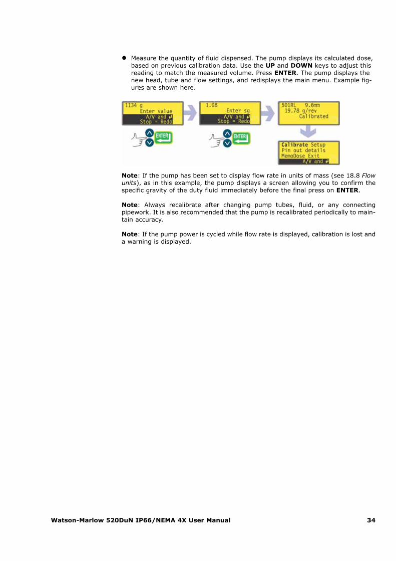
� Measure the quantity of fluid dispensed. The pump displays its calculated dose,based on previous calibration data. Use the UP and DOWN keys to adjust thisreading to match the measured volume. Press ENTER. The pump displays thenew head, tube and flow settings, and redisplays the main menu. Example fig-ures are shown here.
Note: If the pump has been set to display flow rate in units of mass (see 18.8 Flowunits), as in this example, the pump displays a screen allowing you to confirm thespecific gravity of the duty fluid immediately before the final press on ENTER.
Note: Always recalibrate after changing pump tubes, fluid, or any connectingpipework. It is also recommended that the pump is recalibrated periodically to main-tain accuracy.
Note: If the pump power is cycled while flow rate is displayed, calibration is lost anda warning is displayed.
Watson-Marlow 520DuN IP66/NEMA 4X User Manual 35
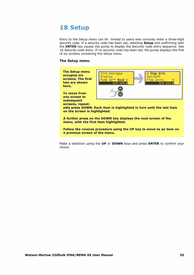
18 Setup
Entry to the Setup menu can be limited to users who correctly enter a three-digitsecurity code. If a security code has been set, selecting Setup and confirming withthe ENTER key causes the pump to display the Security code entry sequence. See16 Security code entry. If no security code has been set, the pump displays the firstof six screens containing the Setup menu.
The Setup menu
Make a selection using the UP or DOWN keys and press ENTER to confirm yourchoice.
The Setup menuoccupies sixscreens. The firsttwo are shownhere.
To move fromone screen tosubsequentscreens, repeat-edly press DOWN. Each item is highlighted in turn until the last itemon the screen is highlighted.
A further press on the DOWN key displays the next screen of themenu, with the first item highlighted.
Follow the reverse procedure using the UP key to move to an item ona previous screen of the menu.
Watson-Marlow 520DuN IP66/NEMA 4X User Manual 36
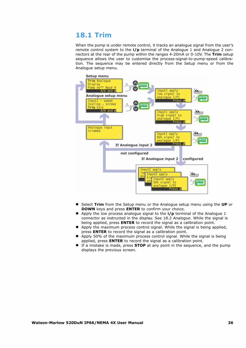
18.1 TrimWhen the pump is under remote control, it tracks an analogue signal from the user’sremote control system to the i/p terminal of the Analogue 1 and Analogue 2 con-nectors at the rear of the pump within the ranges 4-20mA or 0-10V. The Trim setupsequence allows the user to customise the process-signal-to-pump-speed calibra-tion. The sequence may be entered directly from the Setup menu or from theAnalogue setup menu.
� Select Trim from the Setup menu or the Analogue setup menu using the UP orDOWN keys and press ENTER to confirm your choice.
� Apply the low process analogue signal to the i/p terminal of the Analogue 1connector as instructed in the display. See 18.2 Analogue. While the signal isbeing applied, press ENTER to record the signal as a calibration point.
� Apply the maximum process control signal. While the signal is being applied,press ENTER to record the signal as a calibration point.
� Apply 50% of the maximum process control signal. While the signal is beingapplied, press ENTER to record the signal as a calibration point.
� If a mistake is made, press STOP at any point in the sequence, and the pumpdisplays the previous screen.
Watson-Marlow 520DuN IP66/NEMA 4X User Manual 37
� The final press on ENTER ends the Analogue 1 trimming sequence.� If Analogue 2 has been configured, the pump displays a similar sequence of
screens for that input. Apply the low, high and mid-range signal to the i/pterminal of the Analogue 2 connector as instructed in the display, pressingENTER each time to record the signals as calibration points.
� If a mistake is made, press STOP at any point in the sequence, and thepump displays the previous screen.
� The final press on ENTER ends the Analogue 2 trimming sequence.� When trimming is complete the pump displays a confirmation screen and redis-
plays the screen from which it entered the trim sequence: the Setup menu orthe Analogue setup menu.
The pump calculates linear responses from low to mid and from mid to high, andrecords the results as new analogue input calibration graphs.
If any of the three signals applied to each input match, a warning screen is displayedbefore the confirmation screen appears, and the trim is ignored.
Note: By applying the maximum process control signal when the minimum isrequested and vice versa, inverted responses can be set up.
Note: Resetting factory defaults clears the trim calibration values.
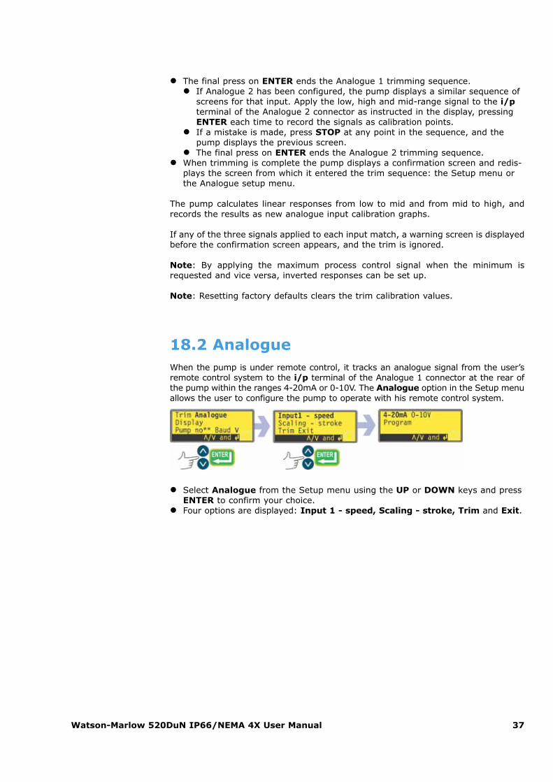
18.2 AnalogueWhen the pump is under remote control, it tracks an analogue signal from the user’sremote control system to the i/p terminal of the Analogue 1 connector at the rear ofthe pump within the ranges 4-20mA or 0-10V. The Analogue option in the Setup menuallows the user to configure the pump to operate with his remote control system.
� Select Analogue from the Setup menu using the UP or DOWN keys and pressENTER to confirm your choice.
� Four options are displayed: Input 1 - speed, Scaling - stroke, Trim and Exit.
Watson-Marlow 520DuN IP66/NEMA 4X User Manual 38
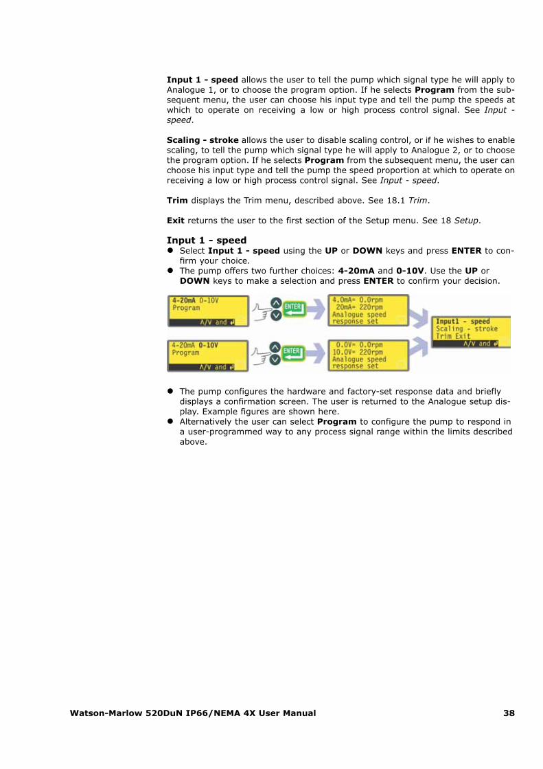
Input 1 - speed allows the user to tell the pump which signal type he will apply toAnalogue 1, or to choose the program option. If he selects Program from the sub-sequent menu, the user can choose his input type and tell the pump the speeds atwhich to operate on receiving a low or high process control signal. See Input -speed.
Scaling - stroke allows the user to disable scaling control, or if he wishes to enablescaling, to tell the pump which signal type he will apply to Analogue 2, or to choosethe program option. If he selects Program from the subsequent menu, the user canchoose his input type and tell the pump the speed proportion at which to operate onreceiving a low or high process control signal. See Input - speed.
Trim displays the Trim menu, described above. See 18.1 Trim.
Exit returns the user to the first section of the Setup menu. See 18 Setup.
Input 1 - speed� Select Input 1 - speed using the UP or DOWN keys and press ENTER to con-
firm your choice.� The pump offers two further choices: 4-20mA and 0-10V. Use the UP or
DOWN keys to make a selection and press ENTER to confirm your decision.
� The pump configures the hardware and factory-set response data and brieflydisplays a confirmation screen. The user is returned to the Analogue setup dis-play. Example figures are shown here.
� Alternatively the user can select Program to configure the pump to respond ina user-programmed way to any process signal range within the limits describedabove.
Watson-Marlow 520DuN IP66/NEMA 4X User Manual 39
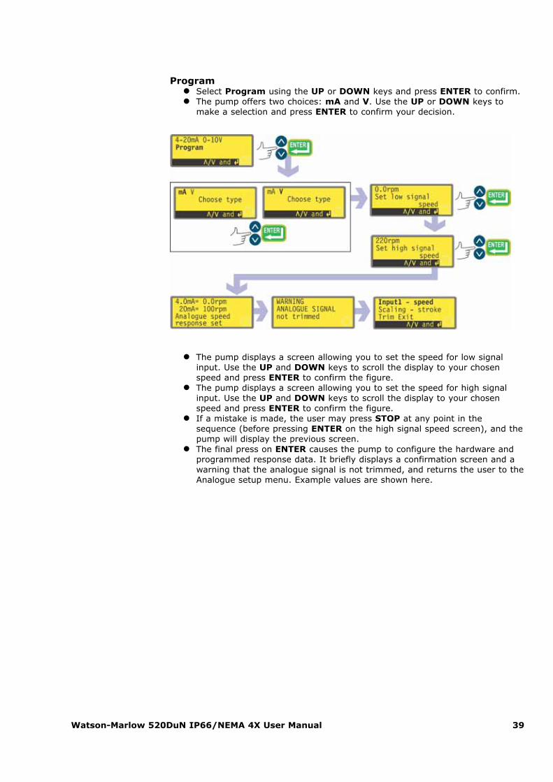
Program� Select Program using the UP or DOWN keys and press ENTER to confirm.� The pump offers two choices: mA and V. Use the UP or DOWN keys to
make a selection and press ENTER to confirm your decision.
� The pump displays a screen allowing you to set the speed for low signalinput. Use the UP and DOWN keys to scroll the display to your chosenspeed and press ENTER to confirm the figure.
� The pump displays a screen allowing you to set the speed for high signalinput. Use the UP and DOWN keys to scroll the display to your chosenspeed and press ENTER to confirm the figure.
� If a mistake is made, the user may press STOP at any point in thesequence (before pressing ENTER on the high signal speed screen), and thepump will display the previous screen.
� The final press on ENTER causes the pump to configure the hardware andprogrammed response data. It briefly displays a confirmation screen and awarning that the analogue signal is not trimmed, and returns the user to theAnalogue setup menu. Example values are shown here.

Watson-Marlow 520DuN IP66/NEMA 4X User Manual 40
Scaling - stroke� Select Scaling - stroke using the UP or DOWN keys and press ENTER to
confirm your choice.� The pump offers five further choices: Off, Keypad, 4-20mA, 0-10V and
Program. Use the UP or DOWN keys to make a selection and press ENTER toconfirm your decision.
� If Off is selected, scaling control is disabled and the pump displays theAnalogue setup menu.
� The other options allow a choice of inputs to control scaling.� If Keypad is selected, scaling will be controlled by keypad entry of the scal-
ing factor while the pump is running in Auto analogue mode.� If 4-20mA or 0-10V is selected, the pump configures the the hardware and
calibration data appropriately. A confirmation screen is displayed briefly andthe user is returned to the Analogue setup screen.
� If Program is selected, the pump offers two choices: mA and V. Use theUP or DOWN keys to make a selection and press ENTER to confirm yourdecision.
� The pump displays a screen inviting the user to enter the required speedproportion for low signal input as a value from 0.0 to 1.0. Enter your valueusing the UP or DOWN keys and confirm by pressing ENTER.
� A similar screen allows the user to enter the required speed proportion forhigh signal input as a value from 0.0 to 1.0. Enter the value in the same way.
� If STOP is pressed at any point in the program setup (before pressingENTER on the high signal speed proportion screen), the pump will displaythe previous screen.
� When high and low values have been entered and confirmed, the pumpconfigures the hardware and basic calibration data. A confirmation screen isdisplayed briefly, followed by a warning that the analogue signal has notbeen trimmed. The user is returned to the Analogue setup screen.
See 22.4 Scaling: analogue input 2 in Automatic control wiring.
Trim
Trim displays the Trim menu, described above. See 18.1 Trim.
It is recommended that a trim calibration is always performed to align the pump’sresponse to the actual process analogue signal.
Exit
Exit returns the user to the first section of the Setup menu, described above. See18 Setup.
Watson-Marlow 520DuN IP66/NEMA 4X User Manual 41
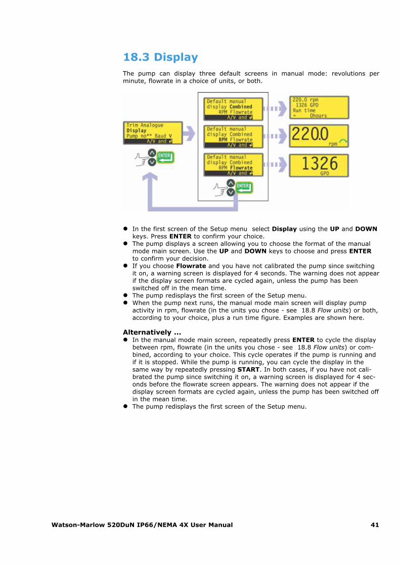
18.3 DisplayThe pump can display three default screens in manual mode: revolutions perminute, flowrate in a choice of units, or both.
� In the first screen of the Setup menu select Display using the UP and DOWNkeys. Press ENTER to confirm your choice.
� The pump displays a screen allowing you to choose the format of the manualmode main screen. Use the UP and DOWN keys to choose and press ENTERto confirm your decision.
� If you choose Flowrate and you have not calibrated the pump since switchingit on, a warning screen is displayed for 4 seconds. The warning does not appearif the display screen formats are cycled again, unless the pump has beenswitched off in the mean time.
� The pump redisplays the first screen of the Setup menu.� When the pump next runs, the manual mode main screen will display pump
activity in rpm, flowrate (in the units you chose - see 18.8 Flow units) or both,according to your choice, plus a run time figure. Examples are shown here.
Alternatively ...� In the manual mode main screen, repeatedly press ENTER to cycle the display
between rpm, flowrate (in the units you chose - see 18.8 Flow units) or com-bined, according to your choice. This cycle operates if the pump is running andif it is stopped. While the pump is running, you can cycle the display in thesame way by repeatedly pressing START. In both cases, if you have not cali-brated the pump since switching it on, a warning screen is displayed for 4 sec-onds before the flowrate screen appears. The warning does not appear if thedisplay screen formats are cycled again, unless the pump has been switched offin the mean time.
� The pump redisplays the first screen of the Setup menu.
Watson-Marlow 520DuN IP66/NEMA 4X User Manual 42
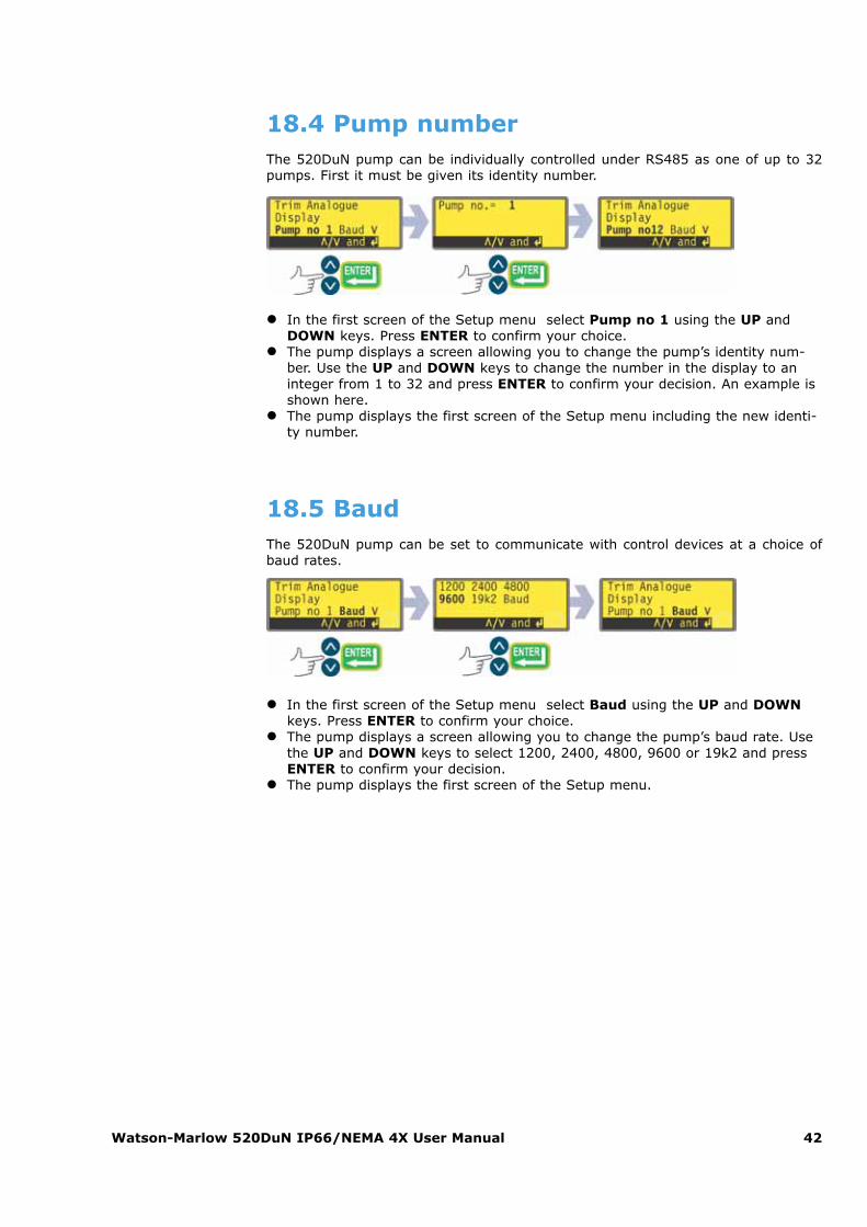
18.4 Pump numberThe 520DuN pump can be individually controlled under RS485 as one of up to 32pumps. First it must be given its identity number.
� In the first screen of the Setup menu select Pump no 1 using the UP andDOWN keys. Press ENTER to confirm your choice.
� The pump displays a screen allowing you to change the pump’s identity num-ber. Use the UP and DOWN keys to change the number in the display to aninteger from 1 to 32 and press ENTER to confirm your decision. An example isshown here.
� The pump displays the first screen of the Setup menu including the new identi-ty number.
18.5 BaudThe 520DuN pump can be set to communicate with control devices at a choice ofbaud rates.
� In the first screen of the Setup menu select Baud using the UP and DOWNkeys. Press ENTER to confirm your choice.
� The pump displays a screen allowing you to change the pump’s baud rate. Usethe UP and DOWN keys to select 1200, 2400, 4800, 9600 or 19k2 and pressENTER to confirm your decision.
� The pump displays the first screen of the Setup menu.
Watson-Marlow 520DuN IP66/NEMA 4X User Manual 43
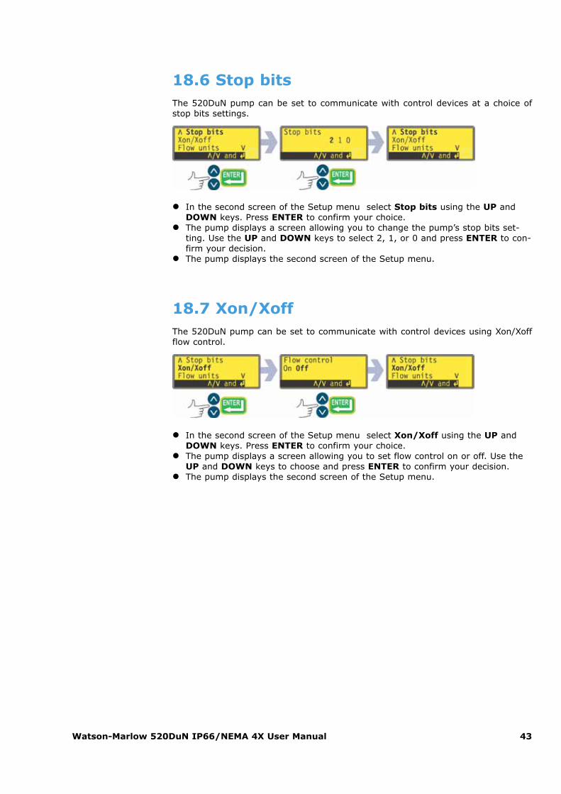
18.6 Stop bitsThe 520DuN pump can be set to communicate with control devices at a choice ofstop bits settings.
� In the second screen of the Setup menu select Stop bits using the UP andDOWN keys. Press ENTER to confirm your choice.
� The pump displays a screen allowing you to change the pump’s stop bits set-ting. Use the UP and DOWN keys to select 2, 1, or 0 and press ENTER to con-firm your decision.
� The pump displays the second screen of the Setup menu.
18.7 Xon/XoffThe 520DuN pump can be set to communicate with control devices using Xon/Xoffflow control.
� In the second screen of the Setup menu select Xon/Xoff using the UP andDOWN keys. Press ENTER to confirm your choice.
� The pump displays a screen allowing you to set flow control on or off. Use theUP and DOWN keys to choose and press ENTER to confirm your decision.
� The pump displays the second screen of the Setup menu.
Watson-Marlow 520DuN IP66/NEMA 4X User Manual 44
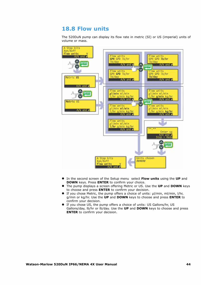
18.8 Flow unitsThe 520DuN pump can display its flow rate in metric (SI) or US (imperial) units ofvolume or mass.
� In the second screen of the Setup menu select Flow units using the UP andDOWN keys. Press ENTER to confirm your choice.
� The pump displays a screen offering Metric or US. Use the UP and DOWN keysto choose and press ENTER to confirm your decision.
� If you chose Metric, the pump offers a choice of units: µl/min, ml/min, l/hr,g/min or kg/hr. Use the UP and DOWN keys to choose and press ENTER toconfirm your decision.
� If you chose US, the pump offers a choice of units: US Gallons/hr, USGallons/day, lb/hr or lb/day. Use the UP and DOWN keys to choose and pressENTER to confirm your decision.
Watson-Marlow 520DuN IP66/NEMA 4X User Manual 45
� If you chose a volumetric flow rate from either screen, a confirmation screenappears briefly and the pump displays the second screen of the Setup menu.
� If you chose a mass flow rate from either screen, the pump asks for the specif-ic gravity of the fluid to be pumped. Use the UP and DOWN keys to enter avalue between 0.01 and 15.00. Press ENTER to confirm your decision. PressSTOP if you decide to make a different choice of units.
� A confirmation screen appears briefly and the pump displays the second screenof the Setup menu.
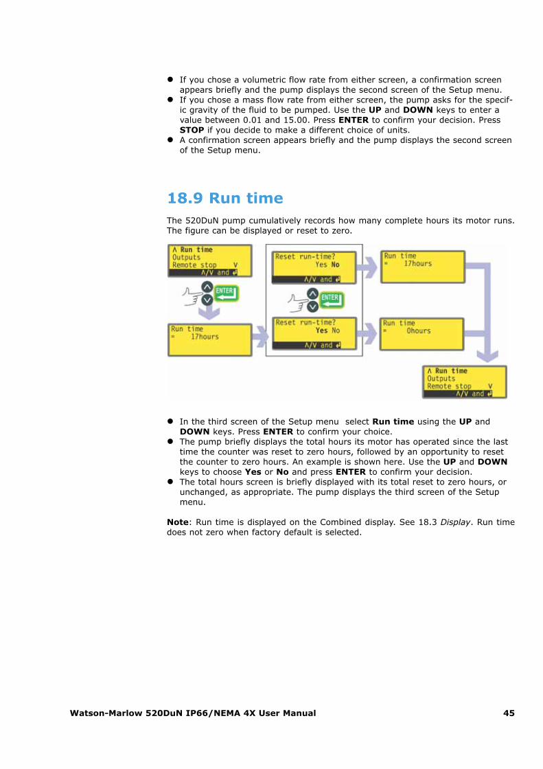
18.9 Run timeThe 520DuN pump cumulatively records how many complete hours its motor runs.The figure can be displayed or reset to zero.
� In the third screen of the Setup menu select Run time using the UP andDOWN keys. Press ENTER to confirm your choice.
� The pump briefly displays the total hours its motor has operated since the lasttime the counter was reset to zero hours, followed by an opportunity to resetthe counter to zero hours. An example is shown here. Use the UP and DOWNkeys to choose Yes or No and press ENTER to confirm your decision.
� The total hours screen is briefly displayed with its total reset to zero hours, orunchanged, as appropriate. The pump displays the third screen of the Setupmenu.
Note: Run time is displayed on the Combined display. See 18.3 Display. Run timedoes not zero when factory default is selected.
Watson-Marlow 520DuN IP66/NEMA 4X User Manual 46
18.10 OutputsThe 520DuN pump offers four relay status outputs. See 12 Switching the pump onfor the first time for initial startup defaults. Each of five parameters can be config-ured to any output, or more than one output.
The parameters are:Run / stop
Provides a status output to indicate whether the pumphead is in a running orstopped condition. When running at 0rpm, the run / stop output indicates run-ning.
DirectionProvides a status output to indicate which direction the pump is set to run in.
Auto / manProvides a status output to indicate whether the pump is in analogue controlmode or manual control mode.
General alarmProvides an alarm output when any system error condition occurs except: leakdetected; analogue signal out of range; analogue over-signal; analogue no sig-nal.
Leak detectedWhen used with a leak detector, this output provides an alarm when the pumphas been automatically switched off following tube failure.
Outputs 1-4 are available as single-pole change-over relay contacts: Relay 1, 2, 3and 4. Connect to the normally open or normally closed contacts of the relay asrequired and configure the pump’s software accordingly. See below in this section.
Note: The maximum rating on the relay contacts of this pump is 30VDC; maximumload 30W.
Watson-Marlow 520DuN IP66/NEMA 4X User Manual 47
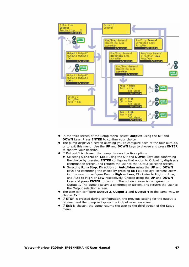
� In the third screen of the Setup menu select Outputs using the UP andDOWN keys. Press ENTER to confirm your choice.
� The pump displays a screen allowing you to configure each of the four outputs,or to exit this menu. Use the UP and DOWN keys to choose and press ENTERto confirm your decision.
� If Output 1 is chosen, the pump displays the five options.� Selecting General or Leak using the UP and DOWN keys and confirming
the choice by pressing ENTER configures that option to Output 1, displays aconfirmation screen, and returns the user to the Output selection screen.
� Selecting Run/Stop, Direction or Auto/Man using the UP and DOWNkeys and confirming the choice by pressing ENTER displays screens allow-ing the user to configure Run to High or Low, Clockwise to High or Low,and Auto to High or Low respectively. Choose using the UP and DOWNkeys and press ENTER to confirm. The option chosen is configured toOutput 1. The pump displays a confirmation screen, and returns the user tothe Output selection screen.
� The user can configure Output 2, Output 3 and Output 4 in the same way, orchoose Exit.
� If STOP is pressed during configuration, the previous setting for the output isretained and the pump redisplays the Output selection screen.
� If Exit is chosen, the pump returns the user to the third screen of the Setupmenu.
Watson-Marlow 520DuN IP66/NEMA 4X User Manual 48
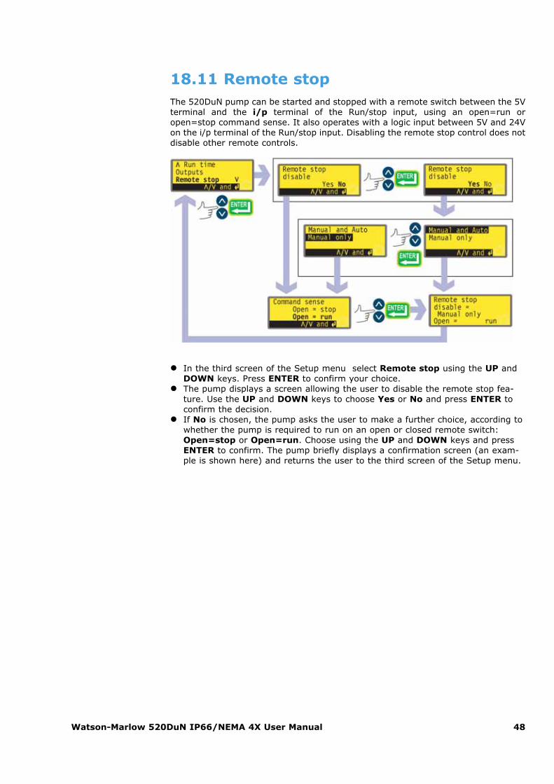
18.11 Remote stopThe 520DuN pump can be started and stopped with a remote switch between the 5Vterminal and the i/p terminal of the Run/stop input, using an open=run oropen=stop command sense. It also operates with a logic input between 5V and 24Von the i/p terminal of the Run/stop input. Disabling the remote stop control does notdisable other remote controls.
� In the third screen of the Setup menu select Remote stop using the UP andDOWN keys. Press ENTER to confirm your choice.
� The pump displays a screen allowing the user to disable the remote stop fea-ture. Use the UP and DOWN keys to choose Yes or No and press ENTER toconfirm the decision.
� If No is chosen, the pump asks the user to make a further choice, according towhether the pump is required to run on an open or closed remote switch:Open=stop or Open=run. Choose using the UP and DOWN keys and pressENTER to confirm. The pump briefly displays a confirmation screen (an exam-ple is shown here) and returns the user to the third screen of the Setup menu.
Watson-Marlow 520DuN IP66/NEMA 4X User Manual 49
� If Yes is chosen, the pump asks the user whether the remote stop feature is tobe disabled fully (for both manual and auto operation), or only for manualoperation, leaving remote stop functioning when the pump is operating in automode. Choose using the UP and DOWN keys and press ENTER to confirm. Ifmanual and auto was chosen, the pump briefly displays a confirmation screen(an example is shown here) and returns the user to the third screen of theSetup menu. If manual only was chosen, the pump asks the user to make afurther choice, according to whether the pump (with remote control available inauto mode only) is required to run on an open or closed remote switch:Open=stop or Open=run. Choose using the UP and DOWN keys and pressENTER to confirm. The pump briefly displays a confirmation screen (an exam-ple is shown here) and returns the user to the third screen of the Setup menu.
� Note: The confirmation screen indicates whether Remote stop is enabled ordisabled, and displays the command sense of the remote control switch even ifRemote stop has been disabled.
Alternatively ...� To toggle the sense of the remote run / stop control between open=stop and
open=run: stop the pump. Turn off the mains power switch at the rear of thepump.
� Hold down the STOP key and the DIRECTION key, and turn on the mainspower switch.
Even with the remote stop function disabled, the pumpcould still start if the remote auto/manual toggle inputis used to toggle the pump into analogue mode.
Watson-Marlow 520DuN IP66/NEMA 4X User Manual 50
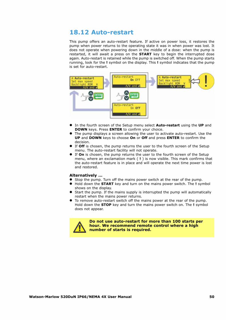
18.12 Auto-restartThis pump offers an auto-restart feature. If active on power loss, it restores thepump when power returns to the operating state it was in when power was lost. Itdoes not operate when powering down in the middle of a dose: when the pump isrestarted, it will await a press on the START key to begin the interrupted doseagain. Auto-restart is retained while the pump is switched off. When the pump startsrunning, look for the ! symbol on the display. This ! symbol indicates that the pumpis set for auto-restart.
� In the fourth screen of the Setup menu select Auto-restart using the UP andDOWN keys. Press ENTER to confirm your choice.
� The pump displays a screen allowing the user to activate auto-restart. Use theUP and DOWN keys to choose On or Off and press ENTER to confirm thedecision.
� If Off is chosen, the pump returns the user to the fourth screen of the Setupmenu. The auto-restart facility will not operate.
� If On is chosen, the pump returns the user to the fourth screen of the Setupmenu, where an exclamation mark ( ! ) is now visible. This mark confirms thatthe auto-restart feature is in place and will operate the next time power is lostand restored.
Alternatively ...� Stop the pump. Turn off the mains power switch at the rear of the pump.� Hold down the START key and turn on the mains power switch. The ! symbol
shows on the display.� Start the pump. If the mains supply is interrupted the pump will automatically
restart when the mains power returns.� To remove auto-restart switch off the mains power at the rear of the pump.
Hold down the STOP key and turn the mains power switch on. The ! symboldoes not appear.
Do not use auto-restart for more than 100 starts perhour. We recommend remote control where a high number of starts is required.
Watson-Marlow 520DuN IP66/NEMA 4X User Manual 51
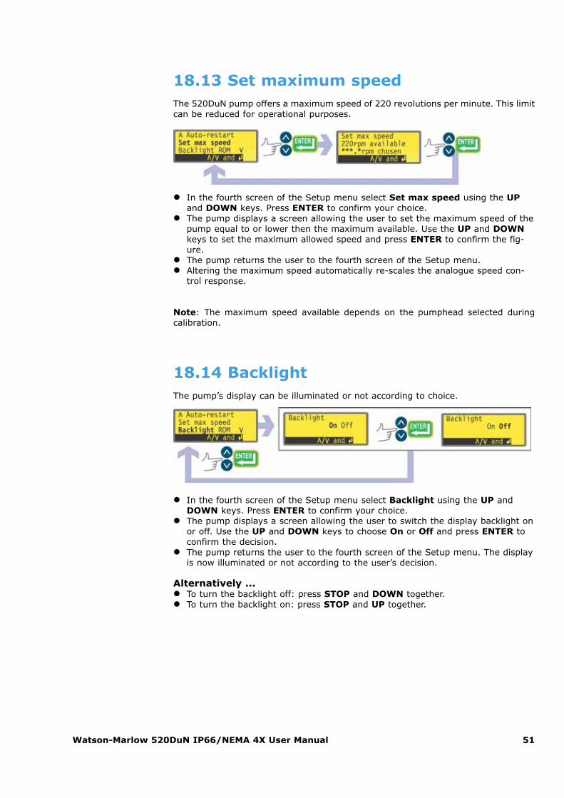
18.13 Set maximum speedThe 520DuN pump offers a maximum speed of 220 revolutions per minute. This limitcan be reduced for operational purposes.
� In the fourth screen of the Setup menu select Set max speed using the UPand DOWN keys. Press ENTER to confirm your choice.
� The pump displays a screen allowing the user to set the maximum speed of thepump equal to or lower then the maximum available. Use the UP and DOWNkeys to set the maximum allowed speed and press ENTER to confirm the fig-ure.
� The pump returns the user to the fourth screen of the Setup menu.� Altering the maximum speed automatically re-scales the analogue speed con-
trol response.
Note: The maximum speed available depends on the pumphead selected during calibration.
18.14 BacklightThe pump’s display can be illuminated or not according to choice.
� In the fourth screen of the Setup menu select Backlight using the UP andDOWN keys. Press ENTER to confirm your choice.
� The pump displays a screen allowing the user to switch the display backlight onor off. Use the UP and DOWN keys to choose On or Off and press ENTER toconfirm the decision.
� The pump returns the user to the fourth screen of the Setup menu. The displayis now illuminated or not according to the user’s decision.
Alternatively ...� To turn the backlight off: press STOP and DOWN together.� To turn the backlight on: press STOP and UP together.
Watson-Marlow 520DuN IP66/NEMA 4X User Manual 52
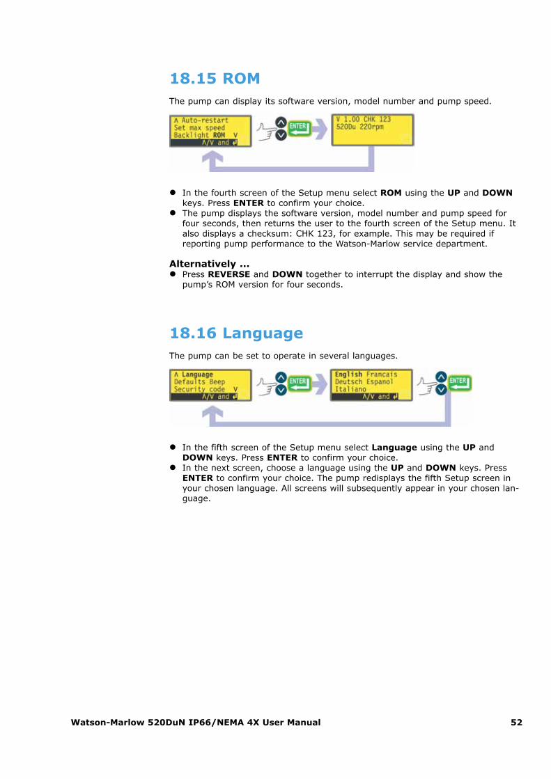
18.15 ROMThe pump can display its software version, model number and pump speed.
� In the fourth screen of the Setup menu select ROM using the UP and DOWNkeys. Press ENTER to confirm your choice.
� The pump displays the software version, model number and pump speed forfour seconds, then returns the user to the fourth screen of the Setup menu. Italso displays a checksum: CHK 123, for example. This may be required ifreporting pump performance to the Watson-Marlow service department.
Alternatively ...� Press REVERSE and DOWN together to interrupt the display and show the
pump’s ROM version for four seconds.
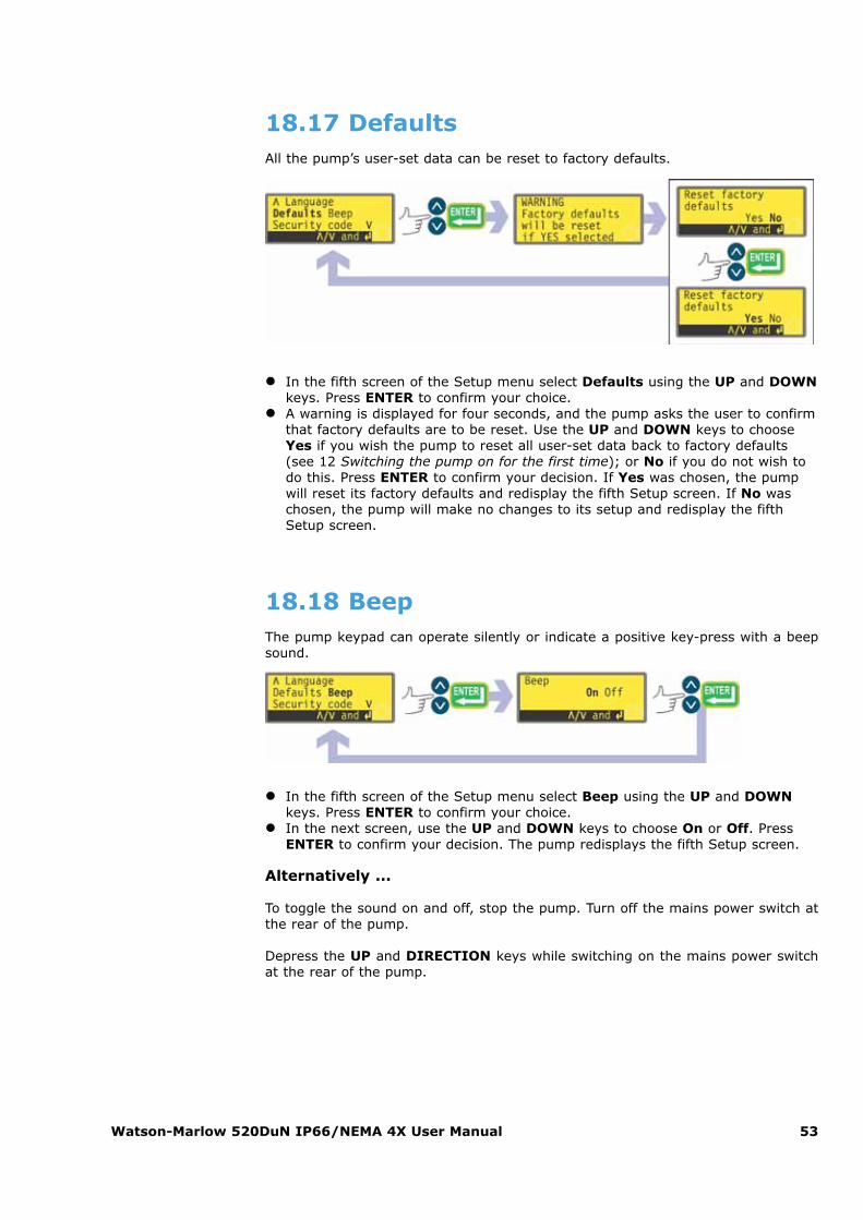
18.16 LanguageThe pump can be set to operate in several languages.
� In the fifth screen of the Setup menu select Language using the UP andDOWN keys. Press ENTER to confirm your choice.
� In the next screen, choose a language using the UP and DOWN keys. PressENTER to confirm your choice. The pump redisplays the fifth Setup screen inyour chosen language. All screens will subsequently appear in your chosen lan-guage.
Watson-Marlow 520DuN IP66/NEMA 4X User Manual 53
18.17 DefaultsAll the pump’s user-set data can be reset to factory defaults.
� In the fifth screen of the Setup menu select Defaults using the UP and DOWNkeys. Press ENTER to confirm your choice.
� A warning is displayed for four seconds, and the pump asks the user to confirmthat factory defaults are to be reset. Use the UP and DOWN keys to chooseYes if you wish the pump to reset all user-set data back to factory defaults(see 12 Switching the pump on for the first time); or No if you do not wish todo this. Press ENTER to confirm your decision. If Yes was chosen, the pumpwill reset its factory defaults and redisplay the fifth Setup screen. If No waschosen, the pump will make no changes to its setup and redisplay the fifthSetup screen.
18.18 BeepThe pump keypad can operate silently or indicate a positive key-press with a beepsound.
� In the fifth screen of the Setup menu select Beep using the UP and DOWNkeys. Press ENTER to confirm your choice.
� In the next screen, use the UP and DOWN keys to choose On or Off. PressENTER to confirm your decision. The pump redisplays the fifth Setup screen.
Alternatively ...
To toggle the sound on and off, stop the pump. Turn off the mains power switch atthe rear of the pump.
Depress the UP and DIRECTION keys while switching on the mains power switchat the rear of the pump.

Watson-Marlow 520DuN IP66/NEMA 4X User Manual 54
18.19 Security codeAccess to the pumpís Setup menu, direction control and keypad lock can be restrict-ed to those who correctly enter a three-digit security code: the main code. A sec-ondary user code can be set, which permits PIN access to direction and keypad lock,but blocks access to Setup. See 18 Setup, 14.1 Keypad functions in manual modeand 14.2 Keypad lock.
The code must first be set.
� In the fifth screen of the Setup menu select Security code using the UP andDOWN keys. Press ENTER to confirm.
� If no code has been set, a screen is displayed inviting the user to set a maincode. Press ENTER to proceed (or STOP to return to the fifth screen of theSetup menu).
� If a main code has been set, a screen is displayed inviting the user to set anew main code, to set a user code (or a new user code if one has already beenset), or to cancel all codes. Choose Set main code, Set user code or Cancelcodes using the UP and DOWN keys. Press ENTER to confirm your choice.
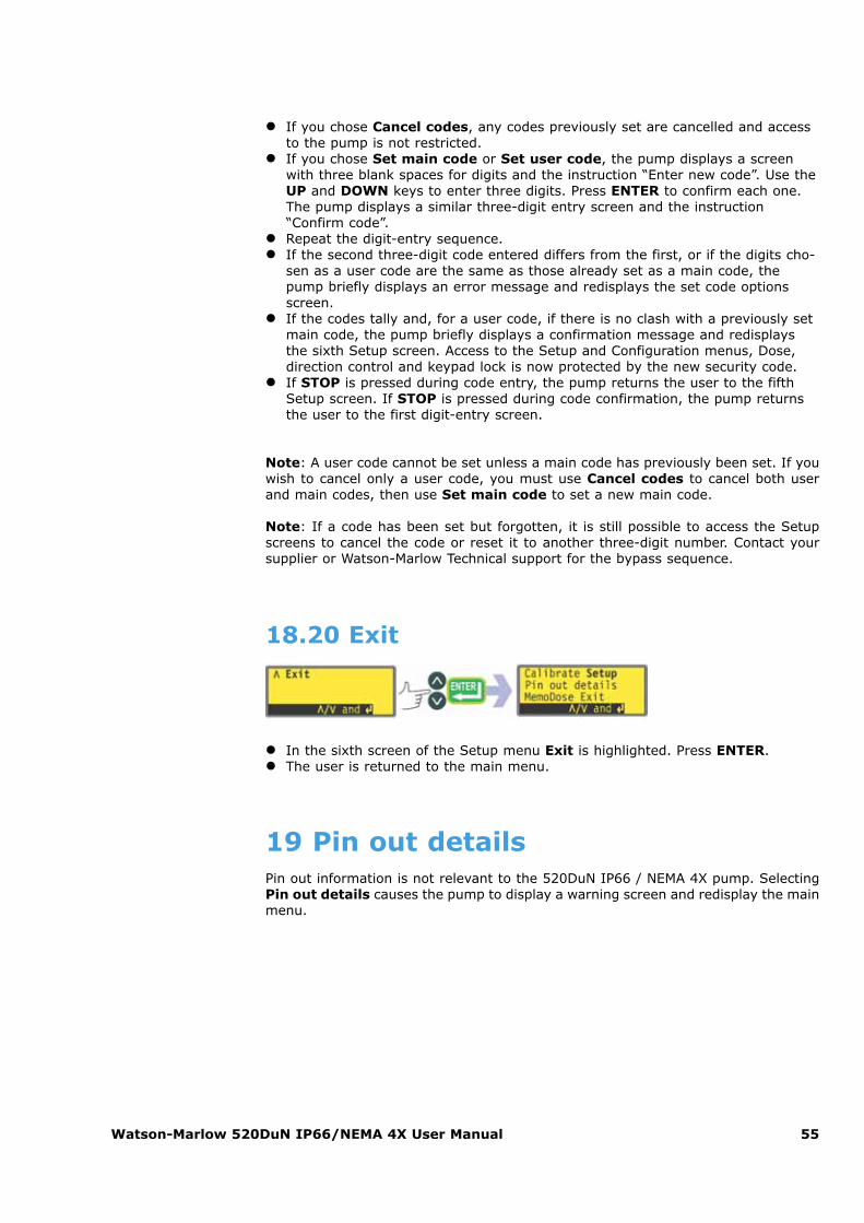
Watson-Marlow 520DuN IP66/NEMA 4X User Manual 55
� If you chose Cancel codes, any codes previously set are cancelled and accessto the pump is not restricted.
� If you chose Set main code or Set user code, the pump displays a screenwith three blank spaces for digits and the instruction “Enter new code”. Use theUP and DOWN keys to enter three digits. Press ENTER to confirm each one.The pump displays a similar three-digit entry screen and the instruction“Confirm code”.
� Repeat the digit-entry sequence.� If the second three-digit code entered differs from the first, or if the digits cho-
sen as a user code are the same as those already set as a main code, thepump briefly displays an error message and redisplays the set code optionsscreen.
� If the codes tally and, for a user code, if there is no clash with a previously setmain code, the pump briefly displays a confirmation message and redisplaysthe sixth Setup screen. Access to the Setup and Configuration menus, Dose,direction control and keypad lock is now protected by the new security code.
� If STOP is pressed during code entry, the pump returns the user to the fifthSetup screen. If STOP is pressed during code confirmation, the pump returnsthe user to the first digit-entry screen.
Note: A user code cannot be set unless a main code has previously been set. If youwish to cancel only a user code, you must use Cancel codes to cancel both userand main codes, then use Set main code to set a new main code.
Note: If a code has been set but forgotten, it is still possible to access the Setupscreens to cancel the code or reset it to another three-digit number. Contact yoursupplier or Watson-Marlow Technical support for the bypass sequence.
18.20 Exit
� In the sixth screen of the Setup menu Exit is highlighted. Press ENTER.� The user is returned to the main menu.
19 Pin out detailsPin out information is not relevant to the 520DuN IP66 / NEMA 4X pump. SelectingPin out details causes the pump to display a warning screen and redisplay the mainmenu.
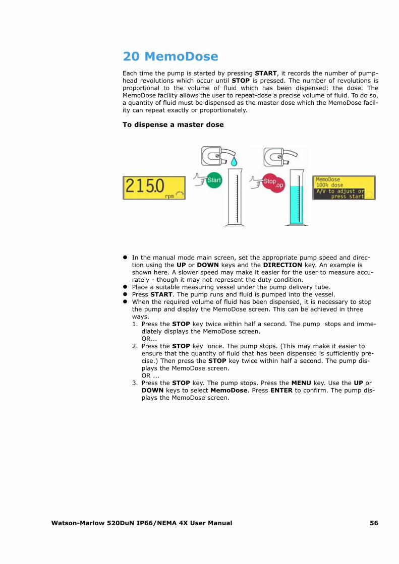
Watson-Marlow 520DuN IP66/NEMA 4X User Manual 56
20 MemoDoseEach time the pump is started by pressing START, it records the number of pump-head revolutions which occur until STOP is pressed. The number of revolutions isproportional to the volume of fluid which has been dispensed: the dose. TheMemoDose facility allows the user to repeat-dose a precise volume of fluid. To do so,a quantity of fluid must be dispensed as the master dose which the MemoDose facil-ity can repeat exactly or proportionately.
To dispense a master dose
� In the manual mode main screen, set the appropriate pump speed and direc-tion using the UP or DOWN keys and the DIRECTION key. An example isshown here. A slower speed may make it easier for the user to measure accu-rately - though it may not represent the duty condition.
� Place a suitable measuring vessel under the pump delivery tube.� Press START. The pump runs and fluid is pumped into the vessel.� When the required volume of fluid has been dispensed, it is necessary to stop
the pump and display the MemoDose screen. This can be achieved in threeways.1. Press the STOP key twice within half a second. The pump stops and imme-
diately displays the MemoDose screen. OR...
2. Press the STOP key once. The pump stops. (This may make it easier toensure that the quantity of fluid that has been dispensed is sufficiently pre-cise.) Then press the STOP key twice within half a second. The pump dis-plays the MemoDose screen.OR ...
3. Press the STOP key. The pump stops. Press the MENU key. Use the UP orDOWN keys to select MemoDose. Press ENTER to confirm. The pump dis-plays the MemoDose screen.
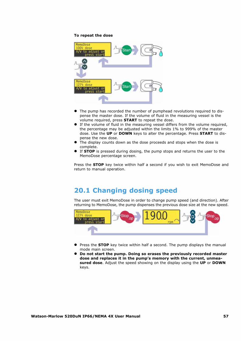
Watson-Marlow 520DuN IP66/NEMA 4X User Manual 57
To repeat the dose
� The pump has recorded the number of pumphead revolutions required to dis-pense the master dose. If the volume of fluid in the measuring vessel is thevolume required, press START to repeat the dose.
� If the volume of fluid in the measuring vessel differs from the volume required,the percentage may be adjusted within the limits 1% to 999% of the masterdose. Use the UP or DOWN keys to alter the percentage. Press START to dis-pense the new dose.
� The display counts down as the dose proceeds and stops when the dose iscomplete.
� If STOP is pressed during dosing, the pump stops and returns the user to theMemoDose percentage screen.
Press the STOP key twice within half a second if you wish to exit MemoDose andreturn to manual operation.
20.1 Changing dosing speedThe user must exit MemoDose in order to change pump speed (and direction). Afterreturning to MemoDose, the pump dispenses the previous dose size at the new speed.
� Press the STOP key twice within half a second. The pump displays the manualmode main screen.
� Do not start the pump. Doing so erases the previously recorded masterdose and replaces it in the pump’s memory with the current, unmea-sured dose. Adjust the speed showing on the display using the UP or DOWNkeys.
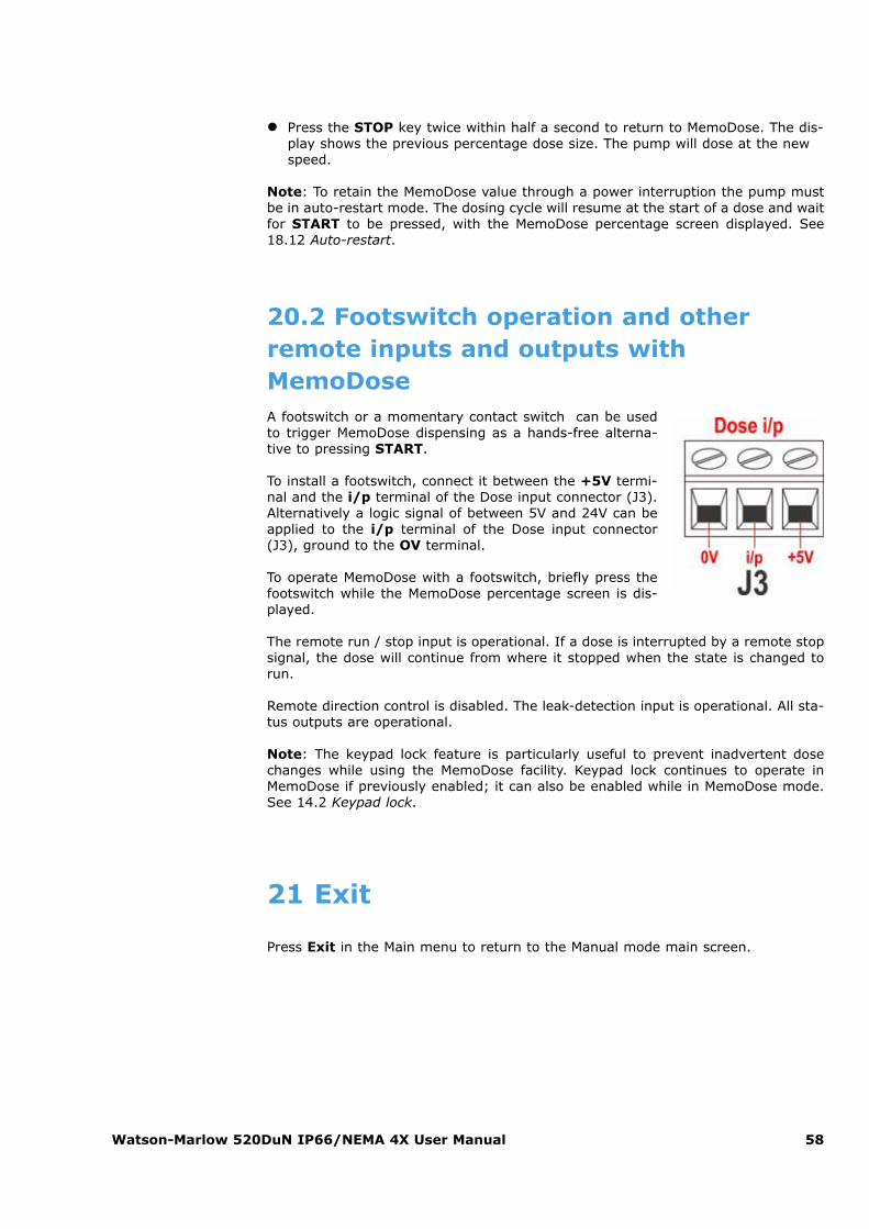
Watson-Marlow 520DuN IP66/NEMA 4X User Manual 58
� Press the STOP key twice within half a second to return to MemoDose. The dis-play shows the previous percentage dose size. The pump will dose at the newspeed.
Note: To retain the MemoDose value through a power interruption the pump mustbe in auto-restart mode. The dosing cycle will resume at the start of a dose and waitfor START to be pressed, with the MemoDose percentage screen displayed. See18.12 Auto-restart.
20.2 Footswitch operation and otherremote inputs and outputs withMemoDoseA footswitch or a momentary contact switch can be usedto trigger MemoDose dispensing as a hands-free alterna-tive to pressing START.
To install a footswitch, connect it between the +5V termi-nal and the i/p terminal of the Dose input connector (J3).Alternatively a logic signal of between 5V and 24V can beapplied to the i/p terminal of the Dose input connector(J3), ground to the OV terminal.
To operate MemoDose with a footswitch, briefly press thefootswitch while the MemoDose percentage screen is dis-played.
The remote run / stop input is operational. If a dose is interrupted by a remote stopsignal, the dose will continue from where it stopped when the state is changed torun.
Remote direction control is disabled. The leak-detection input is operational. All sta-tus outputs are operational.
Note: The keypad lock feature is particularly useful to prevent inadvertent dosechanges while using the MemoDose facility. Keypad lock continues to operate inMemoDose if previously enabled; it can also be enabled while in MemoDose mode.See 14.2 Keypad lock.
21 Exit
Press Exit in the Main menu to return to the Manual mode main screen.
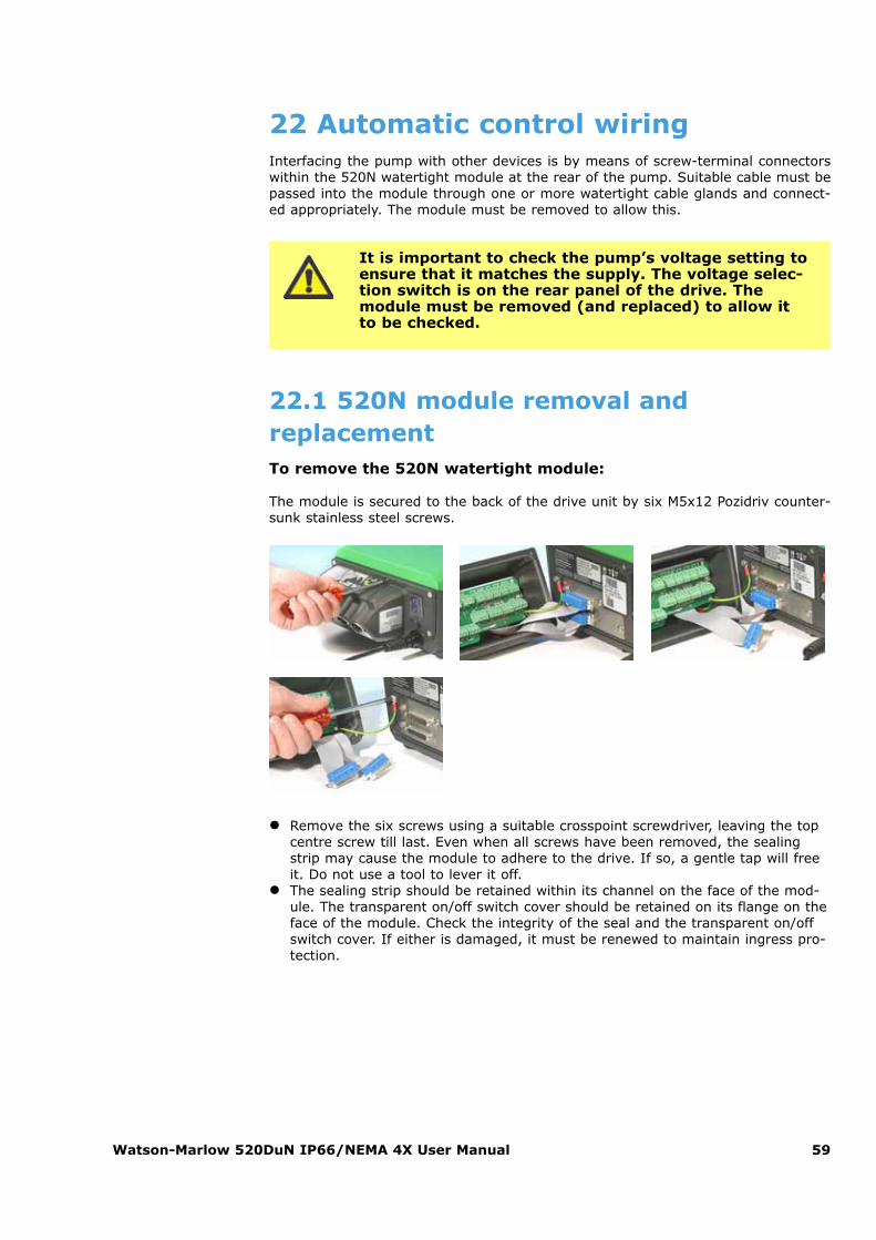
Watson-Marlow 520DuN IP66/NEMA 4X User Manual 59
22 Automatic control wiringInterfacing the pump with other devices is by means of screw-terminal connectorswithin the 520N watertight module at the rear of the pump. Suitable cable must bepassed into the module through one or more watertight cable glands and connect-ed appropriately. The module must be removed to allow this.
It is important to check the pump’s voltage setting toensure that it matches the supply. The voltage selec-tion switch is on the rear panel of the drive. Themodule must be removed (and replaced) to allow itto be checked.
22.1 520N module removal andreplacementTo remove the 520N watertight module:
The module is secured to the back of the drive unit by six M5x12 Pozidriv counter-sunk stainless steel screws.
� Remove the six screws using a suitable crosspoint screwdriver, leaving the topcentre screw till last. Even when all screws have been removed, the sealingstrip may cause the module to adhere to the drive. If so, a gentle tap will freeit. Do not use a tool to lever it off.
� The sealing strip should be retained within its channel on the face of the mod-ule. The transparent on/off switch cover should be retained on its flange on theface of the module. Check the integrity of the seal and the transparent on/offswitch cover. If either is damaged, it must be renewed to maintain ingress pro-tection.
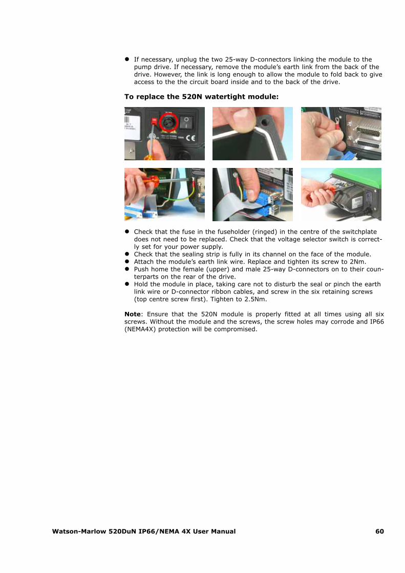
� If necessary, unplug the two 25-way D-connectors linking the module to thepump drive. If necessary, remove the module’s earth link from the back of thedrive. However, the link is long enough to allow the module to fold back to giveaccess to the the circuit board inside and to the back of the drive.
To replace the 520N watertight module:
� Check that the fuse in the fuseholder (ringed) in the centre of the switchplatedoes not need to be replaced. Check that the voltage selector switch is correct-ly set for your power supply.
� Check that the sealing strip is fully in its channel on the face of the module.� Attach the module’s earth link wire. Replace and tighten its screw to 2Nm.� Push home the female (upper) and male 25-way D-connectors on to their coun-
terparts on the rear of the drive.� Hold the module in place, taking care not to disturb the seal or pinch the earth
link wire or D-connector ribbon cables, and screw in the six retaining screws(top centre screw first). Tighten to 2.5Nm.
Note: Ensure that the 520N module is properly fitted at all times using all sixscrews. Without the module and the screws, the screw holes may corrode and IP66(NEMA4X) protection will be compromised.
Watson-Marlow 520DuN IP66/NEMA 4X User Manual 60
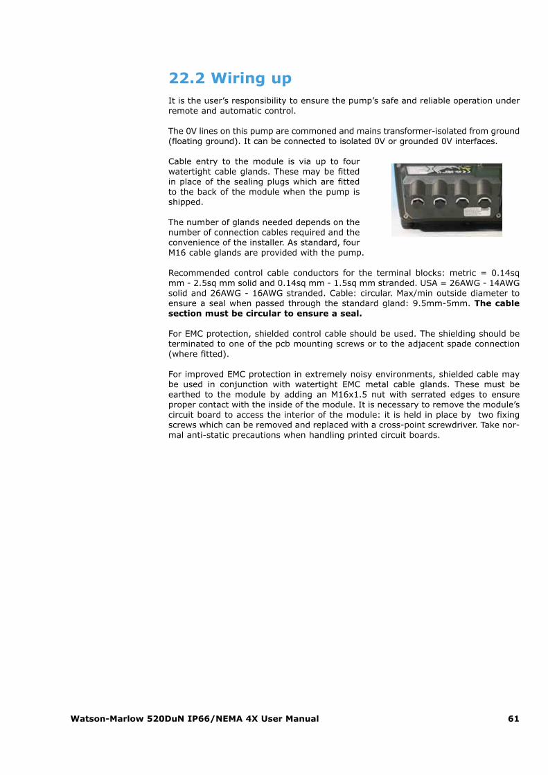
Watson-Marlow 520DuN IP66/NEMA 4X User Manual 61
22.2 Wiring upIt is the user’s responsibility to ensure the pump’s safe and reliable operation underremote and automatic control.
The 0V lines on this pump are commoned and mains transformer-isolated from ground(floating ground). It can be connected to isolated 0V or grounded 0V interfaces.
Cable entry to the module is via up to fourwatertight cable glands. These may be fittedin place of the sealing plugs which are fittedto the back of the module when the pump isshipped.
The number of glands needed depends on thenumber of connection cables required and theconvenience of the installer. As standard, fourM16 cable glands are provided with the pump.
Recommended control cable conductors for the terminal blocks: metric = 0.14sqmm - 2.5sq mm solid and 0.14sq mm - 1.5sq mm stranded. USA = 26AWG - 14AWGsolid and 26AWG - 16AWG stranded. Cable: circular. Max/min outside diameter toensure a seal when passed through the standard gland: 9.5mm-5mm. The cablesection must be circular to ensure a seal.
For EMC protection, shielded control cable should be used. The shielding should beterminated to one of the pcb mounting screws or to the adjacent spade connection(where fitted).
For improved EMC protection in extremely noisy environments, shielded cable maybe used in conjunction with watertight EMC metal cable glands. These must beearthed to the module by adding an M16x1.5 nut with serrated edges to ensureproper contact with the inside of the module. It is necessary to remove the module’scircuit board to access the interior of the module: it is held in place by two fixingscrews which can be removed and replaced with a cross-point screwdriver. Take nor-mal anti-static precautions when handling printed circuit boards.
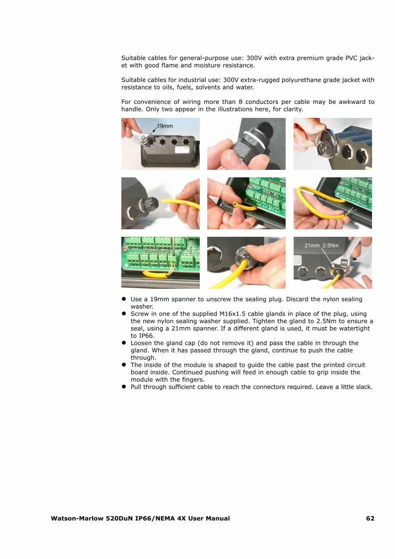
Watson-Marlow 520DuN IP66/NEMA 4X User Manual 62
Suitable cables for general-purpose use: 300V with extra premium grade PVC jack-et with good flame and moisture resistance.
Suitable cables for industrial use: 300V extra-rugged polyurethane grade jacket withresistance to oils, fuels, solvents and water.
For convenience of wiring more than 8 conductors per cable may be awkward tohandle. Only two appear in the illustrations here, for clarity.
� Use a 19mm spanner to unscrew the sealing plug. Discard the nylon sealingwasher.
� Screw in one of the supplied M16x1.5 cable glands in place of the plug, usingthe new nylon sealing washer supplied. Tighten the gland to 2.5Nm to ensure aseal, using a 21mm spanner. If a different gland is used, it must be watertightto IP66.
� Loosen the gland cap (do not remove it) and pass the cable in through thegland. When it has passed through the gland, continue to push the cablethrough.
� The inside of the module is shaped to guide the cable past the printed circuitboard inside. Continued pushing will feed in enough cable to grip inside themodule with the fingers.
� Pull through sufficient cable to reach the connectors required. Leave a little slack.
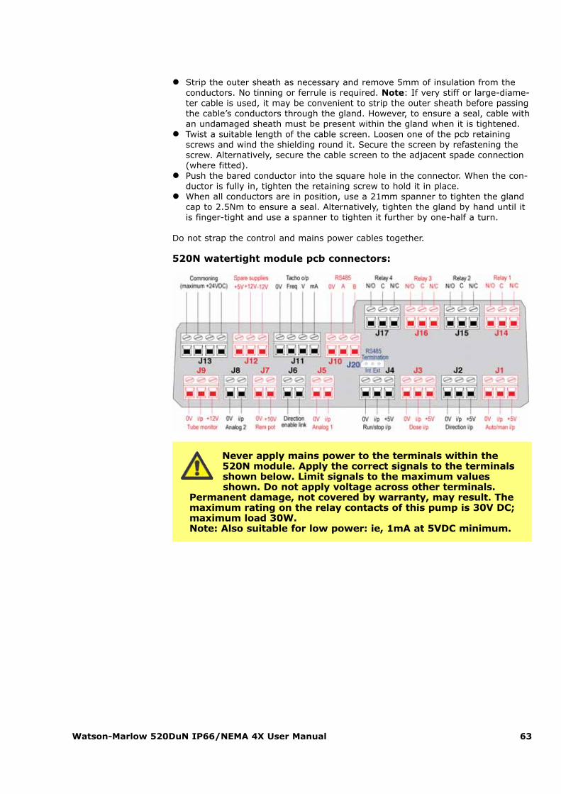
Watson-Marlow 520DuN IP66/NEMA 4X User Manual 63
� Strip the outer sheath as necessary and remove 5mm of insulation from theconductors. No tinning or ferrule is required. Note: If very stiff or large-diame-ter cable is used, it may be convenient to strip the outer sheath before passingthe cable’s conductors through the gland. However, to ensure a seal, cable withan undamaged sheath must be present within the gland when it is tightened.
� Twist a suitable length of the cable screen. Loosen one of the pcb retainingscrews and wind the shielding round it. Secure the screen by refastening thescrew. Alternatively, secure the cable screen to the adjacent spade connection(where fitted).
� Push the bared conductor into the square hole in the connector. When the con-ductor is fully in, tighten the retaining screw to hold it in place.
� When all conductors are in position, use a 21mm spanner to tighten the glandcap to 2.5Nm to ensure a seal. Alternatively, tighten the gland by hand until itis finger-tight and use a spanner to tighten it further by one-half a turn.
Do not strap the control and mains power cables together.
520N watertight module pcb connectors:
Never apply mains power to the terminals within the520N module. Apply the correct signals to the terminalsshown below. Limit signals to the maximum valuesshown. Do not apply voltage across other terminals.
Permanent damage, not covered by warranty, may result. Themaximum rating on the relay contacts of this pump is 30V DC;maximum load 30W. Note: Also suitable for low power: ie, 1mA at 5VDC minimum.
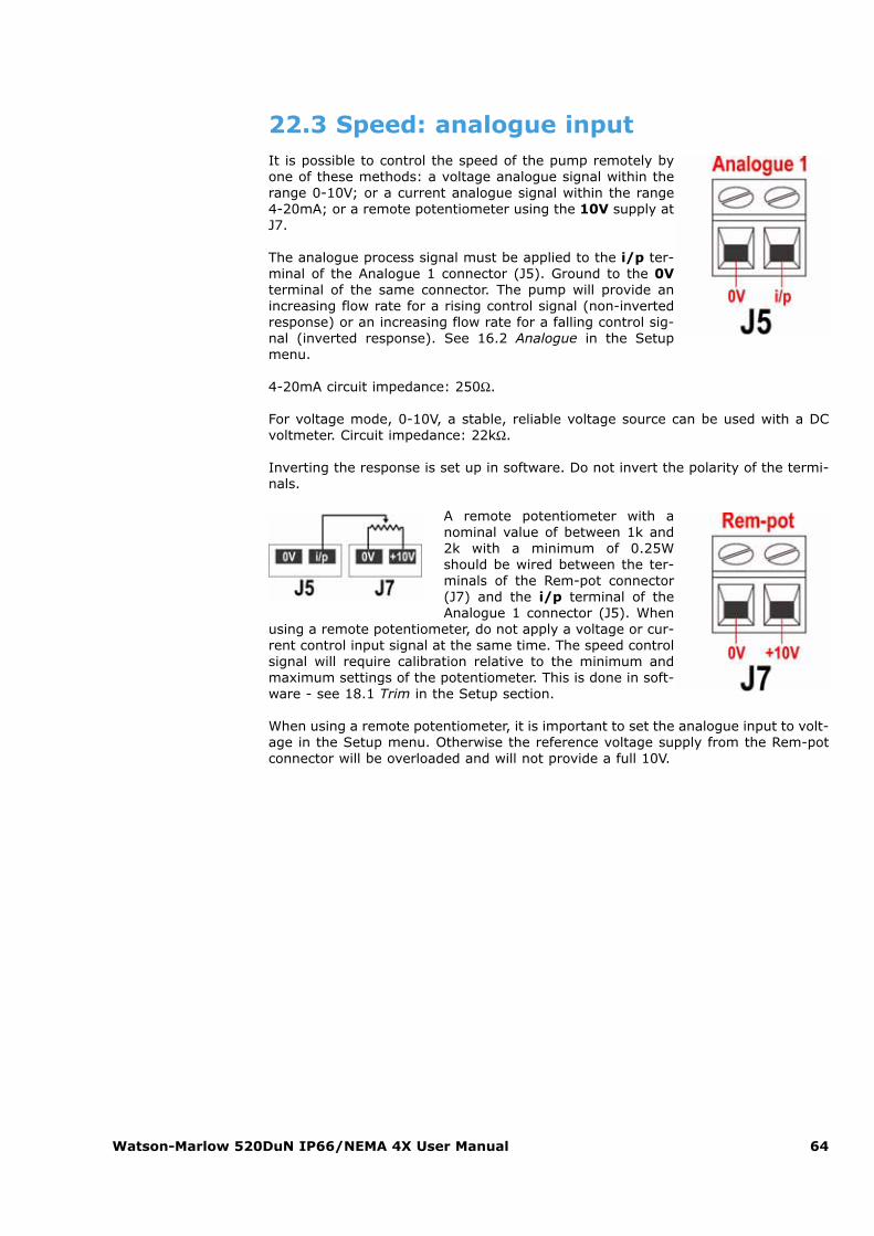
Watson-Marlow 520DuN IP66/NEMA 4X User Manual 64
22.3 Speed: analogue inputIt is possible to control the speed of the pump remotely byone of these methods: a voltage analogue signal within therange 0-10V; or a current analogue signal within the range4-20mA; or a remote potentiometer using the 10V supply atJ7.
The analogue process signal must be applied to the i/p ter-minal of the Analogue 1 connector (J5). Ground to the 0Vterminal of the same connector. The pump will provide anincreasing flow rate for a rising control signal (non-invertedresponse) or an increasing flow rate for a falling control sig-nal (inverted response). See 16.2 Analogue in the Setupmenu.
4-20mA circuit impedance: 250Ω.
For voltage mode, 0-10V, a stable, reliable voltage source can be used with a DCvoltmeter. Circuit impedance: 22kΩ.
Inverting the response is set up in software. Do not invert the polarity of the termi-nals.
A remote potentiometer with anominal value of between 1k and2k with a minimum of 0.25Wshould be wired between the ter-minals of the Rem-pot connector(J7) and the i/p terminal of theAnalogue 1 connector (J5). When
using a remote potentiometer, do not apply a voltage or cur-rent control input signal at the same time. The speed controlsignal will require calibration relative to the minimum andmaximum settings of the potentiometer. This is done in soft-ware - see 18.1 Trim in the Setup section.
When using a remote potentiometer, it is important to set the analogue input to volt-age in the Setup menu. Otherwise the reference voltage supply from the Rem-potconnector will be overloaded and will not provide a full 10V.
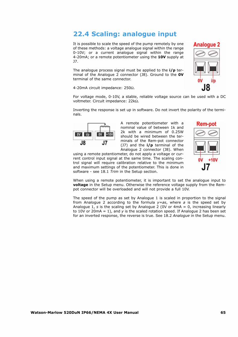
Watson-Marlow 520DuN IP66/NEMA 4X User Manual 65
22.4 Scaling: analogue inputIt is possible to scale the speed of the pump remotely by oneof these methods: a voltage analogue signal within the range0-10V; or a current analogue signal within the range 4-20mA; or a remote potentiometer using the 10V supply atJ7.
The analogue process signal must be applied to the i/p ter-minal of the Analogue 2 connector (J8). Ground to the 0Vterminal of the same connector.
4-20mA circuit impedance: 250Ω.
For voltage mode, 0-10V, a stable, reliable voltage source can be used with a DCvoltmeter. Circuit impedance: 22kΩ.
Inverting the response is set up in software. Do not invert the polarity of the termi-nals.
A remote potentiometer with anominal value of between 1k and2k with a minimum of 0.25Wshould be wired between the ter-minals of the Rem-pot connector(J7) and the i/p terminal of theAnalogue 2 connector (J8). When
using a remote potentiometer, do not apply a voltage or cur-rent control input signal at the same time. The scaling con-trol signal will require calibration relative to the minimumand maximum settings of the potentiometer. This is done insoftware - see 18.1 Trim in the Setup section.
When using a remote potentiometer, it is important to set the analogue input tovoltage in the Setup menu. Otherwise the reference voltage supply from the Rem-pot connector will be overloaded and will not provide a full 10V.
The speed of the pump as set by Analogue 1 is scaled in proportion to the signalfrom Analogue 2 according to the formula y=as, where a is the speed set byAnalogue 1, s is the scaling set by Analogue 2 (0V or 4mA = 0, increasing linearlyto 10V or 20mA = 1), and y is the scaled rotation speed. If Analogue 2 has been setfor an inverted response, the reverse is true. See 18.2 Analogue in the Setup menu.
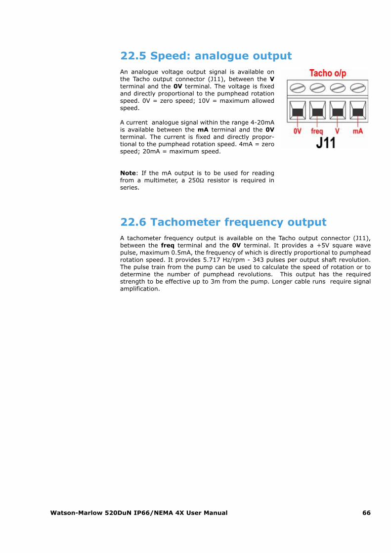
Watson-Marlow 520DuN IP66/NEMA 4X User Manual 66
22.5 Speed: analogue outputAn analogue voltage output signal is available onthe Tacho output connector (J11), between the Vterminal and the 0V terminal. The voltage is fixedand directly proportional to the pumphead rotationspeed. 0V = zero speed; 10V = maximum allowedspeed.
A current analogue signal within the range 4-20mAis available between the mA terminal and the 0Vterminal. The current is fixed and directly propor-tional to the pumphead rotation speed. 4mA = zerospeed; 20mA = maximum speed.
Note: If the mA output is to be used for readingfrom a multimeter, a 250Ω resistor is required inseries.
22.6 Tachometer frequency outputA tachometer frequency output is available on the Tacho output connector (J11),between the freq terminal and the 0V terminal. It provides a +5V square wavepulse, maximum 0.5mA, the frequency of which is directly proportional to pumpheadrotation speed. It provides 5.717 Hz/rpm - 343 pulses per output shaft revolution.The pulse train from the pump can be used to calculate the speed of rotation or todetermine the number of pumphead revolutions. This output has the requiredstrength to be effective up to 3m from the pump. Longer cable runs require signalamplification.
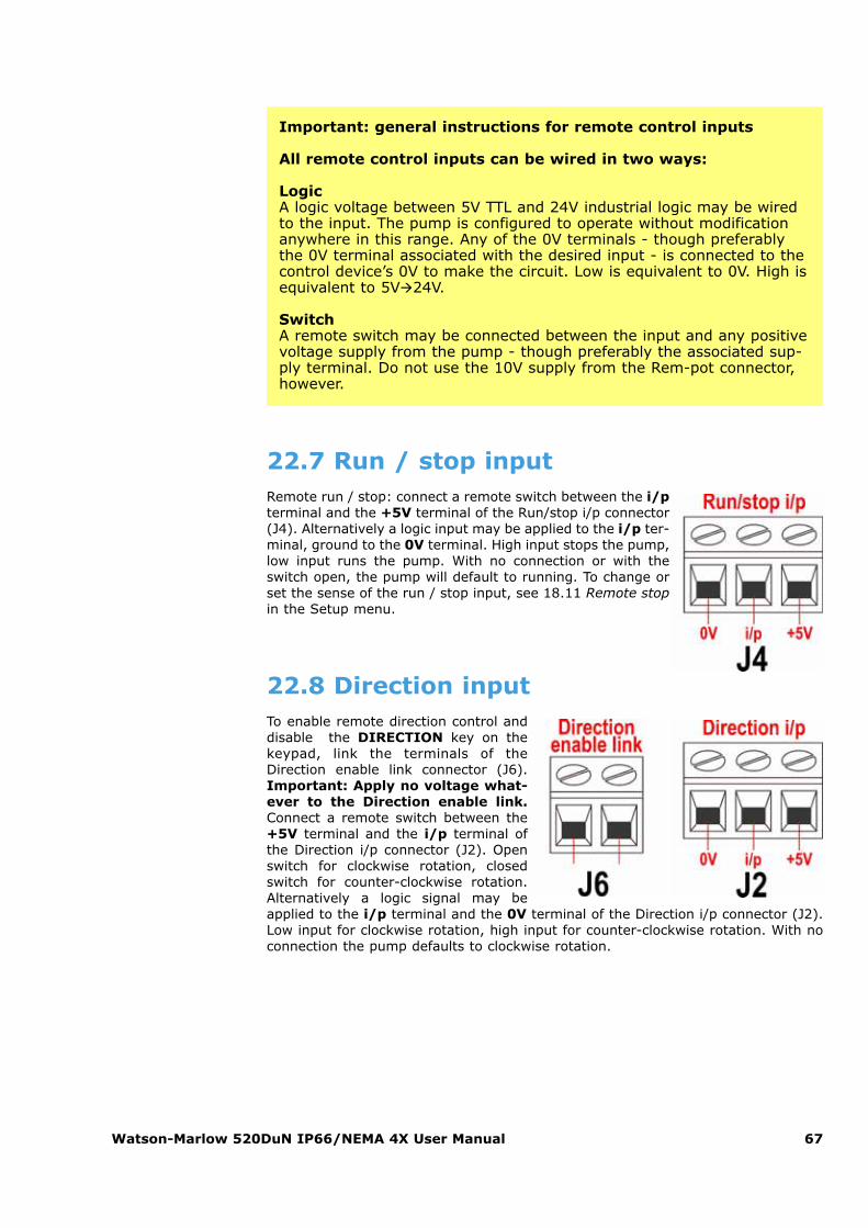
Watson-Marlow 520DuN IP66/NEMA 4X User Manual 67
Important: general instructions for remote control inputs
All remote control inputs can be wired in two ways:
LogicA logic voltage between 5V TTL and 24V industrial logic may be wiredto the input. The pump is configured to operate without modificationanywhere in this range. Any of the 0V terminals - though preferablythe 0V terminal associated with the desired input - is connected to thecontrol device’s 0V to make the circuit. Low is equivalent to 0V. High isequivalent to 5V�24V.
SwitchA remote switch may be connected between the input and any positivevoltage supply from the pump - though preferably the associated sup-ply terminal. Do not use the 10V supply from the Rem-pot connector,however.
22.7 Run / stop inputRemote run / stop: connect a remote switch between the i/pterminal and the +5V terminal of the Run/stop i/p connector(J4). Alternatively a logic input may be applied to the i/p ter-minal, ground to the 0V terminal. High input stops the pump,low input runs the pump. With no connection or with theswitch open, the pump will default to running. To change orset the sense of the run / stop input, see 18.11 Remote stopin the Setup menu.
22.8 Direction inputTo enable remote direction control anddisable the DIRECTION key on thekeypad, link the terminals of theDirection enable link connector (J6).Important: Apply no voltage what-ever to the Direction enable link.Connect a remote switch between the+5V terminal and the i/p terminal ofthe Direction i/p connector (J2). Openswitch for clockwise rotation, closedswitch for counter-clockwise rotation.Alterna tively a logic signal may beapplied to the i/p terminal and the 0V terminal of the Direction i/p connector (J2).Low input for clockwise rotation, high input for counter-clockwise rotation. With noconnection the pump defaults to clockwise rotation.
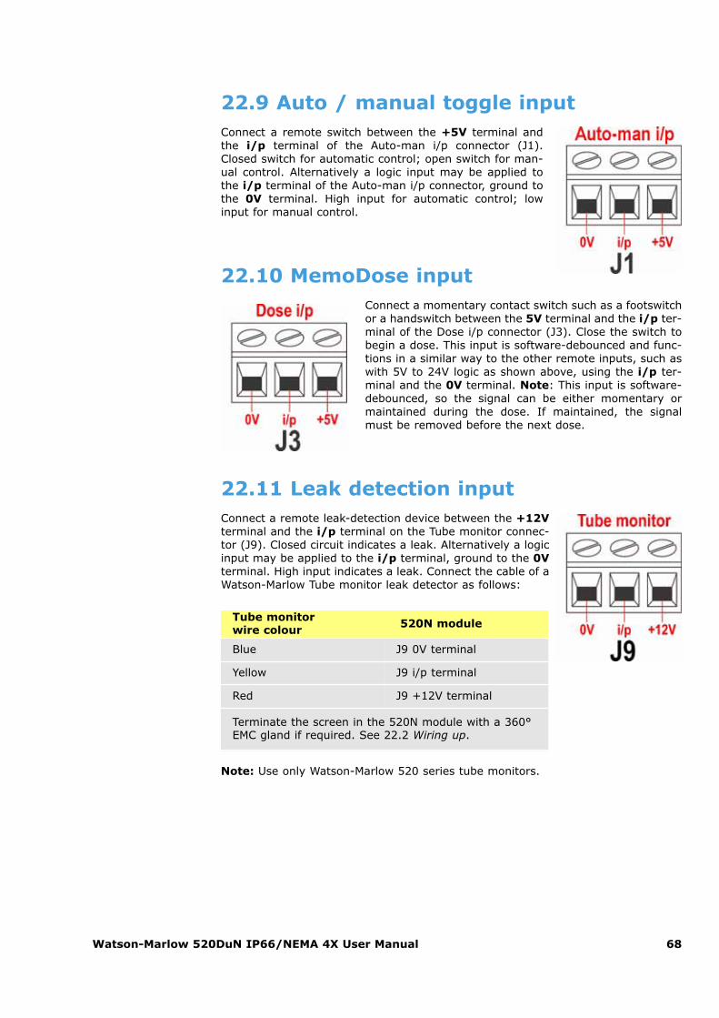
Watson-Marlow 520DuN IP66/NEMA 4X User Manual 68
22.9 Auto / manual toggle inputConnect a remote switch between the +5V terminal andthe i/p terminal of the Auto-man i/p connector (J1).Closed switch for automatic control; open switch for man-ual control. Alternatively a logic input may be applied tothe i/p terminal of the Auto-man i/p connector, ground tothe 0V terminal. High input for automatic control; lowinput for manual control.
22.10 MemoDose inputConnect a momentary contact switch such as a footswitchor a handswitch between the 5V terminal and the i/p ter-minal of the Dose i/p connector (J3). Close the switch tobegin a dose. This input is software-debounced and func-tions in a similar way to the other remote inputs, such aswith 5V to 24V logic as shown above, using the i/p ter-minal and the 0V terminal. Note: This input is software-debounced, so the signal can be either momentary ormaintained during the dose. If maintained, the signalmust be removed before the next dose.
22.11 Leak detection inputConnect a remote leak-detection device between the +12Vterminal and the i/p terminal on the Tube monitor connec-tor (J9). Closed circuit indicates a leak. Alternatively a logicinput may be applied to the i/p terminal, ground to the 0Vterminal. High input indicates a leak. Connect the cable of aWatson-Marlow Tube monitor leak detector as follows:
Note: Use only Watson-Marlow 520 series tube monitors.
Tube monitor wire colour 520N module
Blue J9 0V terminal
Yellow J9 i/p terminal
Red J9 +12V terminal
Terminate the screen in the 520N module with a 360°EMC gland if required. See 22.2 Wiring up.
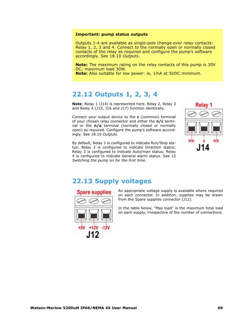
Watson-Marlow 520DuN IP66/NEMA 4X User Manual 69
Important: pump status outputs
Outputs 1-4 are available as single-pole change-over relay contacts:Relay 1, 2, 3 and 4. Connect to the normally open or normally closedcontacts of the relay as required and configure the pump’s softwareaccordingly. See 18.10 Outputs.
Note: The maximum rating on the relay contacts of this pump is 30VDC; maximum load 30W. Note: Also suitable for low power: ie, 1mA at 5VDC minimum.
22.12 Outputs 1, 2, 3, 4Note: Relay 1 (J14) is represented here. Relay 2, Relay 3and Relay 4 (J15, J16 and J17) function identically.
Connect your output device to the c (common) terminalof your chosen relay connector and either the n/c termi-nal or the n/o terminal (normally closed or normallyopen) as required. Configure the pump’s software accord-ingly. See 18.10 Outputs.
By default, Relay 1 is configured to indicate Run/Stop sta-tus; Relay 2 is configured to indicate Direction status;Relay 3 is configured to indicate Auto/man status; Relay4 is configured to indicate General alarm status. See 12Switching the pump on for the first time.
22.13 Supply voltagesAn appropriate voltage supply is available where requiredon each connector. In addition, supplies may be drawnfrom the Spare supplies connector (J12).
In the table below, “Max load” is the maximum total loadon each supply, irrespective of the number of connections.
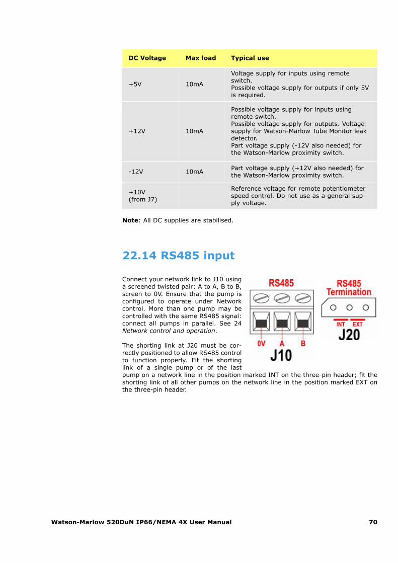
Watson-Marlow 520DuN IP66/NEMA 4X User Manual 70
DC Voltage Max load Typical use
+5V 10mA
Voltage supply for inputs using remoteswitch.Possible voltage supply for outputs if only 5Vis required.
+12V 10mA
Possible voltage supply for inputs usingremote switch.Possible voltage supply for outputs. Voltagesupply for Watson-Marlow Tube Monitor leakdetector.Part voltage supply (-12V also needed) forthe Watson-Marlow proximity switch.
-12V 10mA Part voltage supply (+12V also needed) forthe Watson-Marlow proximity switch.
+10V (from J7)
Reference voltage for remote potentiometerspeed control. Do not use as a general sup-ply voltage.
Note: All DC supplies are stabilised.
22.14 RS485 input
Connect your network link to J10 usinga screened twisted pair: A to A, B to B,screen to 0V. Ensure that the pump isconfigured to operate under Networkcontrol. More than one pump may becontrolled with the same RS485 signal:connect all pumps in parallel. See 24Network control and operation.
The shorting link at J20 must be cor-rectly positioned to allow RS485 controlto function properly. Fit the shortinglink of a single pump or of the lastpump on a network line in the position marked INT on the three-pin header; fit theshorting link of all other pumps on the network line in the position marked EXT onthe three-pin header.
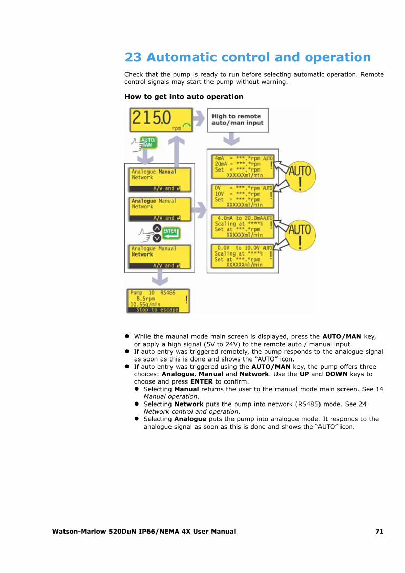
Watson-Marlow 520DuN IP66/NEMA 4X User Manual 71
23 Automatic control and operationCheck that the pump is ready to run before selecting automatic operation. Remotecontrol signals may start the pump without warning.
How to get into auto operation
� While the maunal mode main screen is displayed, press the AUTO/MAN key,or apply a high signal (5V to 24V) to the remote auto / manual input.
� If auto entry was triggered remotely, the pump responds to the analogue signalas soon as this is done and shows the “AUTO” icon.
� If auto entry was triggered using the AUTO/MAN key, the pump offers threechoices: Analogue, Manual and Network. Use the UP and DOWN keys tochoose and press ENTER to confirm.� Selecting Manual returns the user to the manual mode main screen. See 14
Manual operation.� Selecting Network puts the pump into network (RS485) mode. See 24
Network control and operation.� Selecting Analogue puts the pump into analogue mode. It responds to the
analogue signal as soon as this is done and shows the “AUTO” icon.
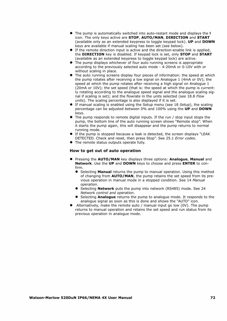
Watson-Marlow 520DuN IP66/NEMA 4X User Manual 72
� The pump is automatically switched into auto-restart mode and displays the !icon. The only keys active are STOP, AUTO/MAN, DIRECTION and START(available only as an extended keypress to toggle keypad lock). UP and DOWNkeys are available if manual scaling has been set (see below).
� If the remote direction input is active and the direction-enable link is applied,the DIRECTION key is disabled. If keypad lock is set, only STOP and START(available as an extended keypress to toggle keypad lock) are active.
� The pump displays whichever of four auto running screens is appropriateaccording to the previously selected auto mode - 4-20mA or 0-10V with orwithout scaling in place.
� The auto running screens display four pieces of information: the speed at whichthe pump rotates after receiving a low signal on Analogue 1 (4mA or 0V); thespeed at which the pump rotates after receiving a high signal on Analogue 1(20mA or 10V); the set speed (that is: the speed at which the pump is current-ly rotating according to the analogue speed signal and the analogue scaling sig-nal if scaling is set); and the flowrate in the units selected (see 18.8 Flowunits). The scaling percentage is also displayed if it is set.
� If manual scaling is enabled using the Setup menu (see 18 Setup), the scalingpercentage can be adjusted between 0% and 100% using the UP and DOWNkeys.
� The pump responds to remote digital inputs. If the run / stop input stops thepump, the bottom line of the auto running screen shows “Remote stop”. Whenit starts the pump again, this will disappear and the pump returns to normalrunning mode.
� If the pump is stopped because a leak is detected, the screen displays “LEAKDETECTED. Check and reset, then press Stop”. See 25.1 Error codes.
� The remote status outputs operate fully.
How to get out of auto operation
� Pressing the AUTO/MAN key displays three options: Analogue, Manual andNetwork. Use the UP and DOWN keys to choose and press ENTER to con-firm.� Selecting Manual returns the pump to manual operation. Using this method
of changing from AUTO/MAN, the pump retains the set speed from its pre-vious operation in manual mode in a stopped condition. See 14 Manualoperation.
� Selecting Network puts the pump into network (RS485) mode. See 24Network control and operation.
� Selecting Analogue returns the pump to analogue mode. It responds to theanalogue signal as soon as this is done and shows the “AUTO” icon.
� Alternatively, make the remote auto / manual input go low (0V). The pumpreturns to manual operation and retains the set speed and run status from itsprevious operation in analogue mode.
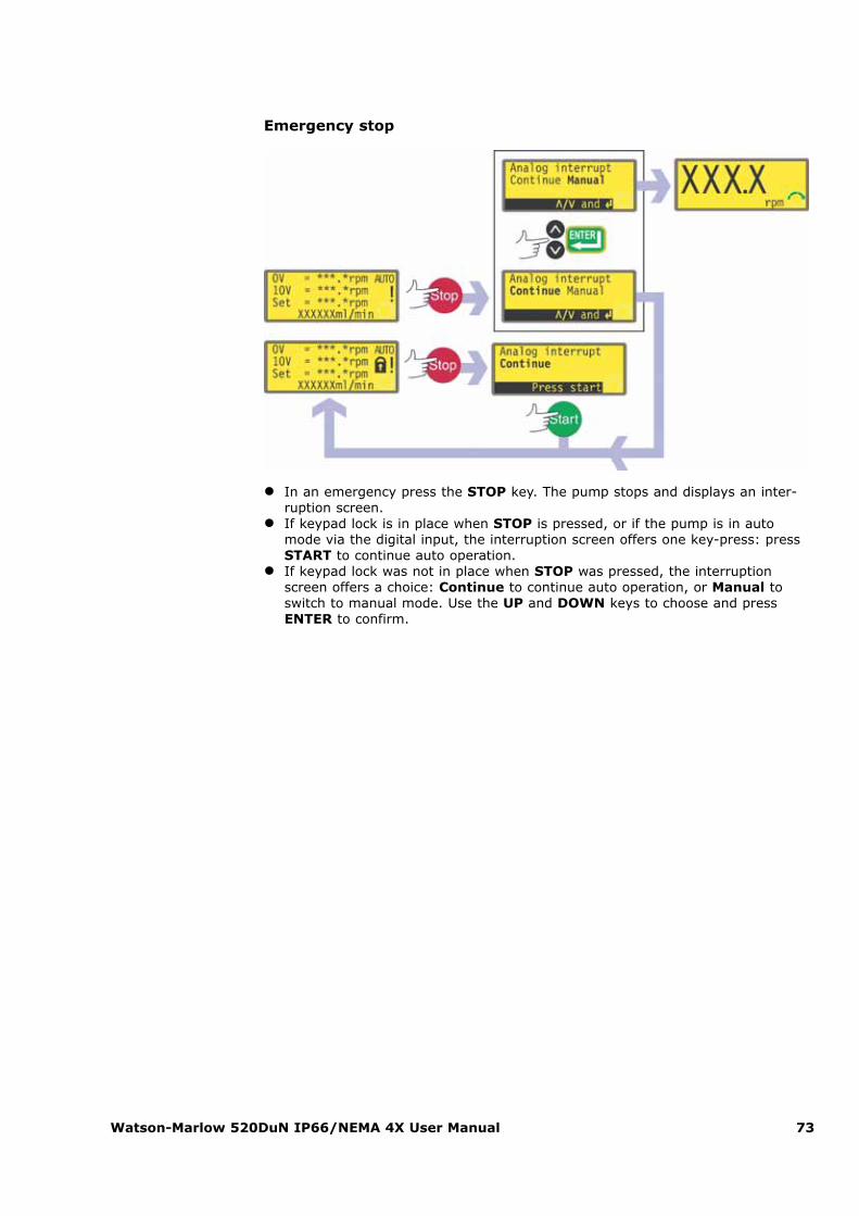
Watson-Marlow 520DuN IP66/NEMA 4X User Manual 73
Emergency stop
� In an emergency press the STOP key. The pump stops and displays an inter-ruption screen.
� If keypad lock is in place when STOP is pressed, or if the pump is in automode via the digital input, the interruption screen offers one key-press: pressSTART to continue auto operation.
� If keypad lock was not in place when STOP was pressed, the interruptionscreen offers a choice: Continue to continue auto operation, or Manual toswitch to manual mode. Use the UP and DOWN keys to choose and pressENTER to confirm.
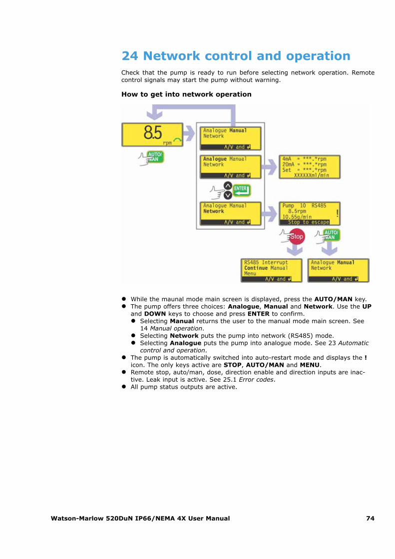
Watson-Marlow 520DuN IP66/NEMA 4X User Manual 74
24 Network control and operationCheck that the pump is ready to run before selecting network operation. Remotecontrol signals may start the pump without warning.
How to get into network operation
� While the maunal mode main screen is displayed, press the AUTO/MAN key.� The pump offers three choices: Analogue, Manual and Network. Use the UP
and DOWN keys to choose and press ENTER to confirm.� Selecting Manual returns the user to the manual mode main screen. See
14 Manual operation.� Selecting Network puts the pump into network (RS485) mode.� Selecting Analogue puts the pump into analogue mode. See 23 Automatic
control and operation.� The pump is automatically switched into auto-restart mode and displays the !
icon. The only keys active are STOP, AUTO/MAN and MENU.� Remote stop, auto/man, dose, direction enable and direction inputs are inac-
tive. Leak input is active. See 25.1 Error codes.� All pump status outputs are active.
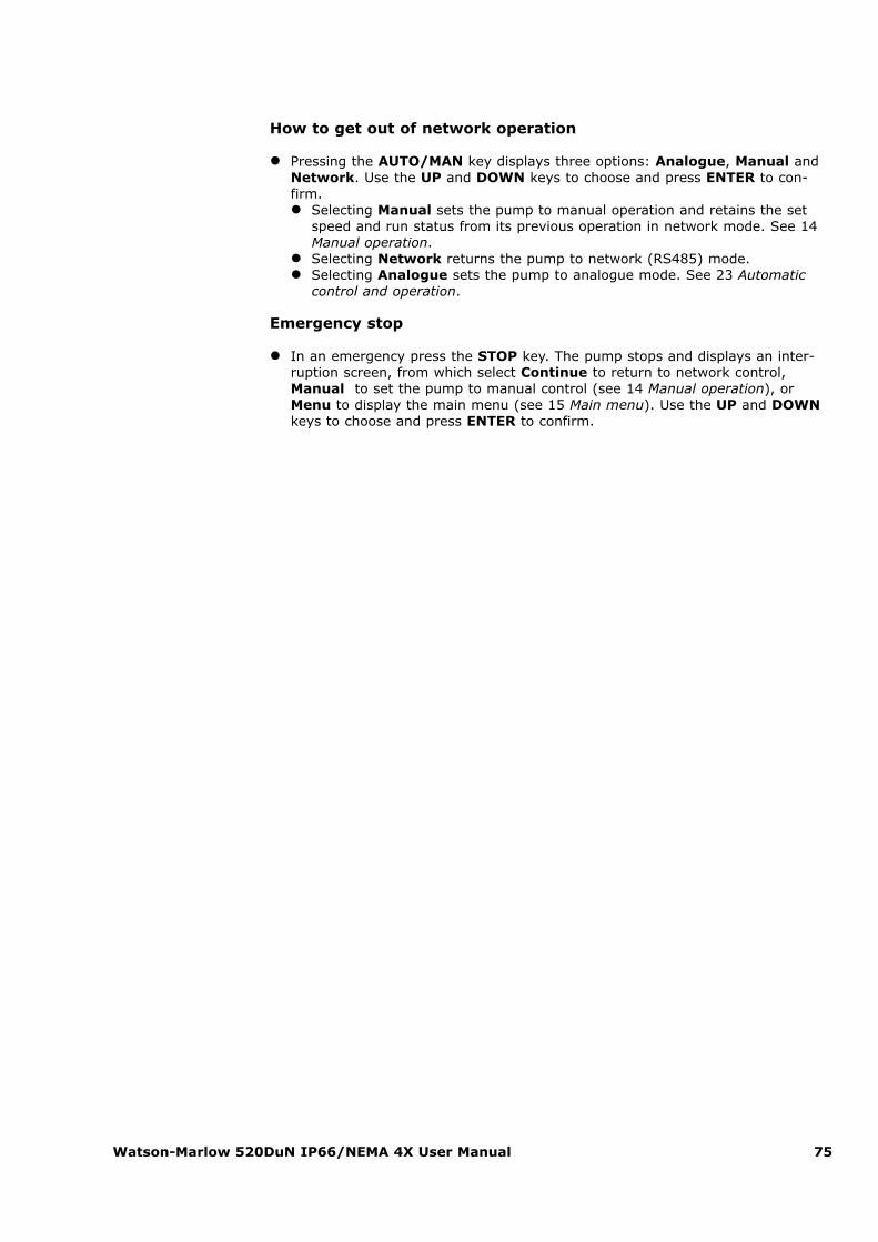
Watson-Marlow 520DuN IP66/NEMA 4X User Manual 75
How to get out of network operation
� Pressing the AUTO/MAN key displays three options: Analogue, Manual andNetwork. Use the UP and DOWN keys to choose and press ENTER to con-firm.� Selecting Manual sets the pump to manual operation and retains the set
speed and run status from its previous operation in network mode. See 14Manual operation.
� Selecting Network returns the pump to network (RS485) mode.� Selecting Analogue sets the pump to analogue mode. See 23 Automatic
control and operation.
Emergency stop
� In an emergency press the STOP key. The pump stops and displays an inter-ruption screen, from which select Continue to return to network control,Manual to set the pump to manual control (see 14 Manual operation), orMenu to display the main menu (see 15 Main menu). Use the UP and DOWNkeys to choose and press ENTER to confirm.

Watson-Marlow 520DuN IP66/NEMA 4X User Manual 76
24.1 RS485 command strings
Command Parameters Meaning
nCA - Clear LCD display
nCH - Home the cursor
nDO xxxxxxxxxx<,yyyyy>
Set and run one dose of xxxxxxxxxxtacho pulses, with optional drip of yyyyy(maximum 11,000) tacho pulses. Seenote 1
nTC - Clear the cumulative tachometer count
nSP xxx.x Set speed to xxx.x rpm
nSI - Increment speed by 1rpm
nSD - Decrement speed by 1rpm
nGO - Start running
nST - Stop running
nRC - Change direction
nRR - Set direction to clockwise
nRL - Set direction to counter-clockwise
nRS - Return status. See note 2
nRT - Return the cumulative tachometer count
nW [line 1]~[line 2]~[line 3]~[line 4]@
Display text on 1 to 4 lines with ~ asthe line delimiter. Terminated by the @character. See note 3
nZY - Return 0 for stopped or 1 for running
Note 1: The correlation between tachometer pulses and motor rotation is fixedand provides a measurable and absolute way of monitoring the number of rev-olutions of the gearbox output shaft - 10,982 pulses per revolution. This in turnallows the count to be equated to the amount of material dispensed - assumingthat the pumphead type and tube size are known.
Note 2: The status is returned to the sender in the following format: [pumptype] [ml/rev] [pumphead] [tube size] [speed] [CW/CCW] P/N [pump number][tacho count] [0/1 (stopped/running)] !
For example: 520Du 15.84 520R 9.6MM 220.0 CW P/N 1 123456789 1 !
Note 3: If the pump speed is changed subsequently, the pump must display thescreen shown here (example figures only) for 4 seconds before reverting to thecustom display. 1 to 4 lines of text can be written with ~as the line delimiter and @ as the message end.
i.e., 1W520Du@ and 1W520Du~@ are both valid commands.
Note 4: In all cases 'n' can be any number from 1 to 32 inclusive, and by excep-tion the # symbol can be used as an all-drives command; but not with the RS,RT or ZY commands, as the results would be indeterminate.

Watson-Marlow 520DuN IP66/NEMA 4X User Manual 77
25 TroubleshootingIf the pump display remains blank when the pump is on, make the following checks:
� Check the position of the voltage selector switch. The voltage selector ismounted in the switchplate at the rear of the pump, protected from water bythe 520N module. The module must be removed to allow access to the switch-plate. See 22.1 520N module removal and replacement.
� Check the mains power switch at the rear of the pump.� Check that mains power is available to the pump.� Check the fuse in the fuseholder in the centre of the switchplate at the rear of
the pump.� Check the fuse in the mains power plug if one is present.
If the pump runs but there is little or no flow, make the following checks:
� Check that the tube and rotor are in the pumphead.� Check that fluid is supplied to the pump.� Check that the tube is not split or burst.� Check for any kinks or blockages in the lines.� Check that any valves in the lines are open.� Check that the correct wall-thickness tube is being used.� Check direction of rotation.� Check that the rotor is not slipping on the drive shaft.

Watson-Marlow 520DuN IP66/NEMA 4X User Manual 78
25.1 Error codesIf an internal error occurs, a flashing error screen is displayed. Note: Signal out ofrange, Over signal, No signal and Leak detected error screens report the natureof an external signal. They do not flash.
Error condition Suggested action
RAM write error Attempt to reset by switching power OFF / ON. Or seeksupport
RAM corruption Attempt to reset by switching power OFF / ON. Or seeksupport
OTP ROM error /corruption
Attempt to reset by switching power OFF / ON. Or seeksupport
OTP ROM readerror
Attempt to reset by switching power OFF / ON. Or seeksupport
Unknown pumptype
Check the interface card and cables. Attempt to reset byswitching power OFF / ON. Or seek support
Display failure Seek support
Wrong key-press Attempt key-press again. Attempt to reset by switching OFF/ ON
Motor stalled Stop pump immediately. Check pumphead and tube. PowerOFF/ON may reset. Or seek support
Tacho fault Stop pump immediately. Power OFF/ON may reset. Or seeksupport
Speed error Stop pump immediately. Power OFF/ON may reset. Or seeksupport
Over current Stop pump immediately. Check system. Power OFF/ON mayreset. Or seek support
Over voltageStop pump immediately. Check mains voltage selectorswitch. Check supply. Power OFF/ON may reset. Or seeksupport
Under voltage Stop pump immediately. Check mains voltage selectorswitch. Check supply. ON/OFF may reset. Or seek support
Watchdog error Attempt to reset by switching power OFF / ON. Or seeksupport
Over temperature Stop pump immediately. Turn OFF. Seek supportSignal out ofrange
Check analogue control signal range. Trim signal asrequired. Or seek support
Over signal Reduce the analogue control signal
No signal Connect analogue control signal or return to manual controlLeak detected.Check and reset Remove the cause of any leak. The STOP key resets
Unrecognisedkey-press
Attempt key-press again. Attempt to reset by switchingpower OFF/ON. Or seek support
Work overloadTurn OFF. Check power supply. Check pumphead andtubing. Wait 30 minutes. Power ON may reset. Or seeksupport
Network notdetected Turn OFF. Check network and connections. Or seek support
RS485 fault Turn OFF. Check network and connections. Or seek support
RS485 lost Turn OFF. Check network and connections. Or seek support
General error condition Turn OFF. Seek support
Watson-Marlow 520DuN IP66/NEMA 4X User Manual 79
26 Drive maintenanceThere are no user serviceable parts inside the pump (except the power cable:see 10 Connecting this product to a power supply). The unit should bereturned to Watson-Marlow or its appointed agents or distributors for service.
27 Drive spares
Replaceable main fuse, type T2,5A H 250V 20mm: FS0064 Foot: MN2507M
Module seal: MN2507M
Module pcb: MNA2066A Module switch cover:MN2505M
Glands: GR0056 Blanking plugs: GR0057
Sealing washer for blanking plug and gland:GR0058 Snap-fit vent: MN2513B
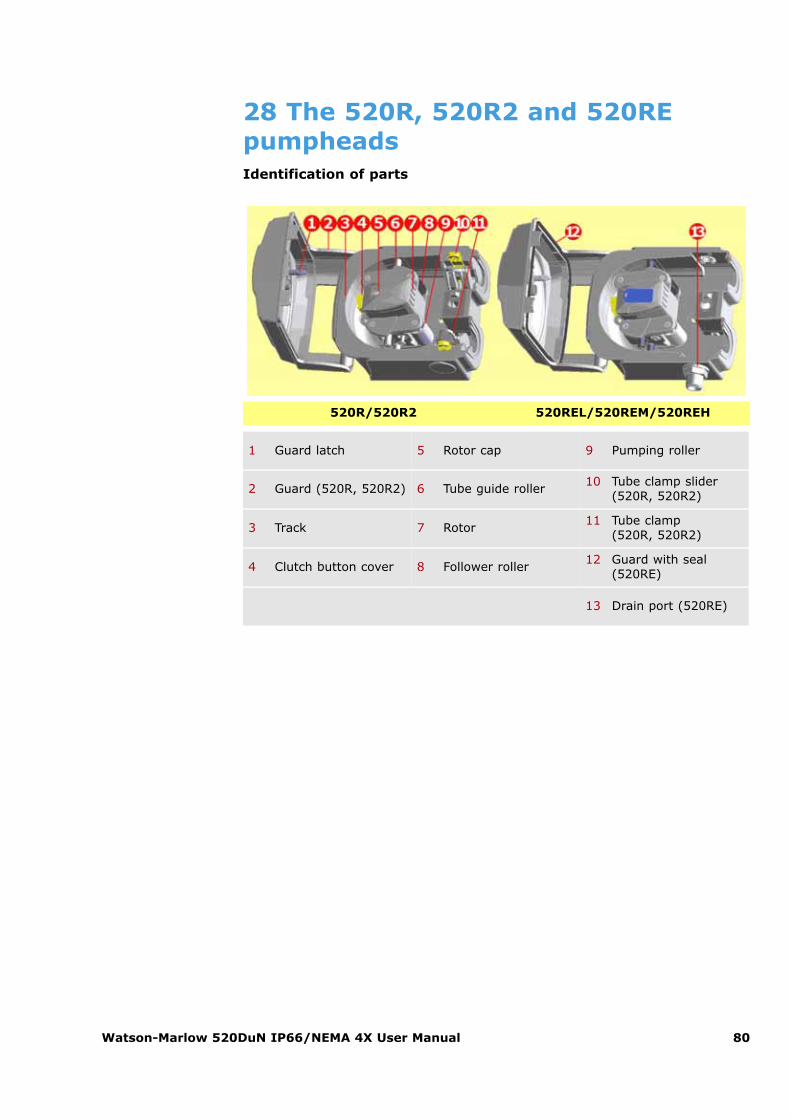
Watson-Marlow 520DuN IP66/NEMA 4X User Manual 80
28 The 520R, 520R2 and 520REpumpheadsIdentification of parts
1 Guard latch 5 Rotor cap 9 Pumping roller
2 Guard (520R, 520R2) 6 Tube guide roller10 Tube clamp slider
(520R, 520R2)
3 Track 7 Rotor11 Tube clamp
(520R, 520R2)
4 Clutch button cover 8 Follower roller12 Guard with seal
(520RE)
13 Drain port (520RE)
520R/520R2 520REL/520REM/520REH

Watson-Marlow 520DuN IP66/NEMA 4X User Manual 81
28.1 Pumphead position, removal andreplacement
The pumphead track can be fitted in one of three orientations to provide right, upor down input/output port positions, whichever is convenient. Position the pump-head so that the tube ports face up or down only where the drive is placed on thebench edge - otherwise the pump tube or the hinged guard will impact the bench.Do not position the pumphead so that the tube ports face the keypad. Doing so mayresult in a safety risk.
The pump can be configured for clockwise or counter-clockwise rotor rotation. Pleasenote, however, that tube life will be greater if the rotor rotates clockwise; and thatperformance against pressure will be maximized if the rotor rotates counter-clock-wise.
To reposition the track� Open the pumphead guard as described under 27.1 Opening the pumphead
guard, below.� Remove the rotor as described under Rotor removal, below.
� Undo and withdraw the four track-retaining screws using a slotted screwdriver.� Remove the track.� Relocate the track in the desired position. Replace and tighten the track-retain-
ing screws.� Replace the rotor as described under Rotor replacement below.� Close the guard, pushing it fully home until the latch engages.
Always isolate the pump from the mains power sup-ply before opening the guard or performing any posi-tioning, removal or maintenance activity.
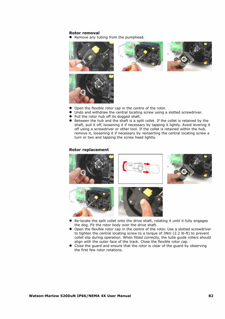
Watson-Marlow 520DuN IP66/NEMA 4X User Manual 82
Rotor removal� Remove any tubing from the pumphead.
� Open the flexible rotor cap in the centre of the rotor.� Undo and withdraw the central locating screw using a slotted screwdriver.� Pull the rotor hub off its dogged shaft.� Between the hub and the shaft is a split collet. If the collet is retained by the
shaft, pull it off, loosening it if necessary by tapping it lightly. Avoid levering itoff using a screwdriver or other tool. If the collet is retained within the hub,remove it, loosening it if necessary by reinserting the central locating screw aturn or two and tapping the screw head lightly.
Rotor replacement
� Re-locate the split collet onto the drive shaft, rotating it until it fully engagesthe dog. Fit the rotor body over the drive shaft.
� Open the flexible rotor cap in the centre of the rotor. Use a slotted screwdriverto tighten the central locating screw to a torque of 3Nm (2.2 lb-ft) to preventcollet slip during operation. When fitted correctly, the tube guide rollers shouldalign with the outer face of the track. Close the flexible rotor cap.
� Close the guard and ensure that the rotor is clear of the guard by observingthe first few rotor rotations.
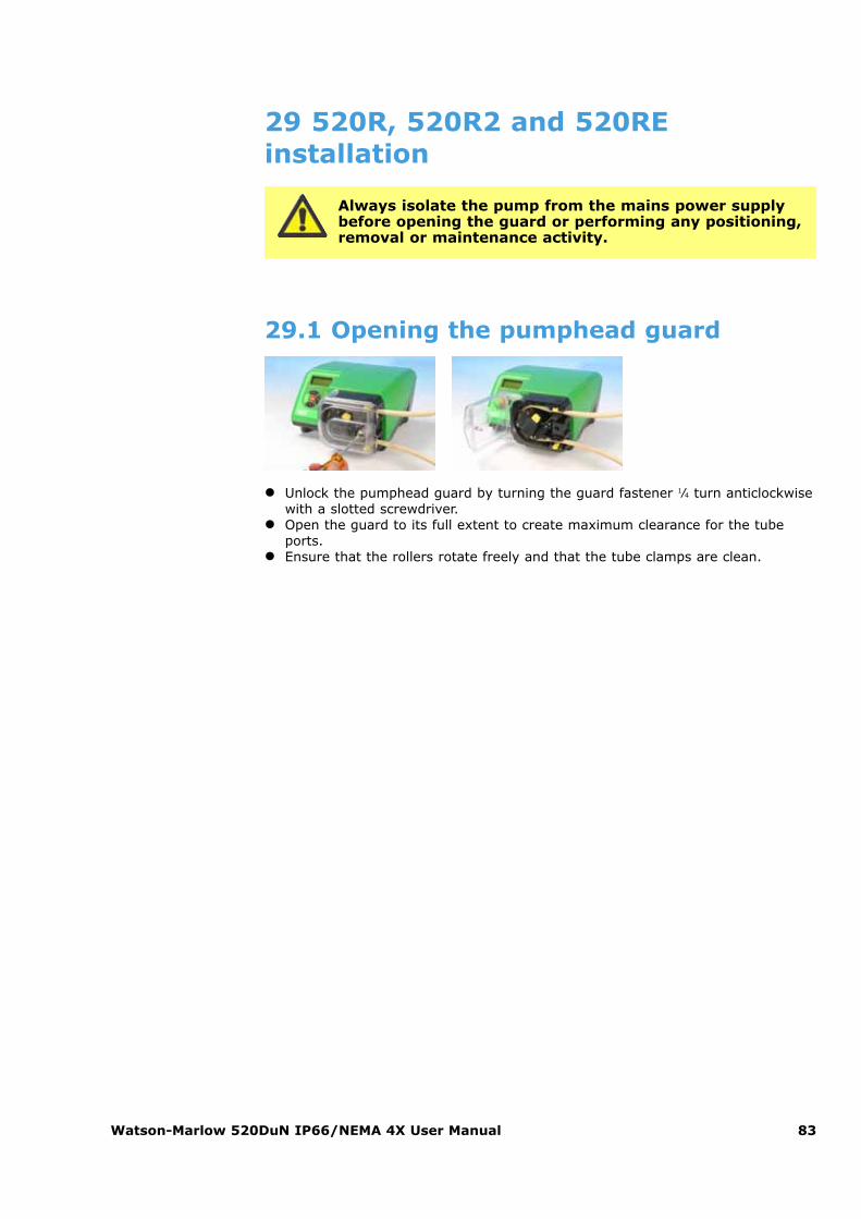
Watson-Marlow 520DuN IP66/NEMA 4X User Manual 83
29 520R, 520R2 and 520REinstallation
29.1 Opening the pumphead guard
� Unlock the pumphead guard by turning the guard fastener 1⁄4 turn anticlockwisewith a slotted screwdriver.
� Open the guard to its full extent to create maximum clearance for the tubeports.
� Ensure that the rollers rotate freely and that the tube clamps are clean.
Always isolate the pump from the mains power supplybefore opening the guard or performing any positioning,removal or maintenance activity.
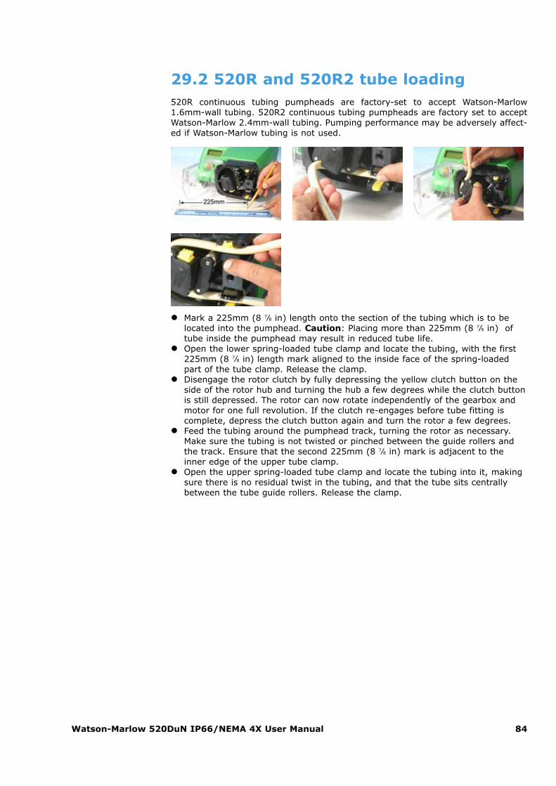
Watson-Marlow 520DuN IP66/NEMA 4X User Manual 84
29.2 520R and 520R2 tube loading520R continuous tubing pumpheads are factory-set to accept Watson-Marlow1.6mm-wall tubing. 520R2 continuous tubing pumpheads are factory set to acceptWatson-Marlow 2.4mm-wall tubing. Pumping performance may be adversely affect-ed if Watson-Marlow tubing is not used.
� Mark a 225mm (8 7⁄8 in) length onto the section of the tubing which is to belocated into the pumphead. Caution: Placing more than 225mm (8 7⁄8 in) oftube inside the pumphead may result in reduced tube life.
� Open the lower spring-loaded tube clamp and locate the tubing, with the first225mm (8 7⁄8 in) length mark aligned to the inside face of the spring-loadedpart of the tube clamp. Release the clamp.
� Disengage the rotor clutch by fully depressing the yellow clutch button on theside of the rotor hub and turning the hub a few degrees while the clutch buttonis still depressed. The rotor can now rotate independently of the gearbox andmotor for one full revolution. If the clutch re-engages before tube fitting iscomplete, depress the clutch button again and turn the rotor a few degrees.
� Feed the tubing around the pumphead track, turning the rotor as necessary.Make sure the tubing is not twisted or pinched between the guide rollers andthe track. Ensure that the second 225mm (8 7⁄8 in) mark is adjacent to theinner edge of the upper tube clamp.
� Open the upper spring-loaded tube clamp and locate the tubing into it, makingsure there is no residual twist in the tubing, and that the tube sits centrallybetween the tube guide rollers. Release the clamp.
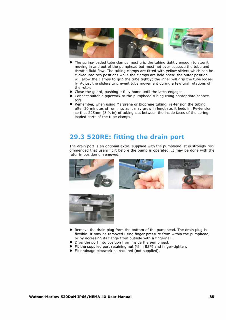
Watson-Marlow 520DuN IP66/NEMA 4X User Manual 85
� The spring-loaded tube clamps must grip the tubing tightly enough to stop itmoving in and out of the pumphead but must not over-squeeze the tube andthrottle fluid flow. The tubing clamps are fitted with yellow sliders which can beclicked into two positions while the clamps are held open: the outer positionwill allow the clamps to grip the tube tightly; the inner will grip the tube loose-ly. Adjust the sliders to prevent tube movement during a few trial rotations ofthe rotor.
� Close the guard, pushing it fully home until the latch engages.� Connect suitable pipework to the pumphead tubing using appropriate connec-
tors.� Remember, when using Marprene or Bioprene tubing, re-tension the tubing
after 30 minutes of running, as it may grow in length as it beds in. Re-tensionso that 225mm (8 7⁄8 in) of tubing sits between the inside faces of the spring-loaded parts of the tube clamps.
29.3 520RE: fitting the drain portThe drain port is an optional extra, supplied with the pumphead. It is strongly rec-ommended that users fit it before the pump is operated. It may be done with therotor in position or removed.
� Remove the drain plug from the bottom of the pumphead. The drain plug isflexible. It may be removed using finger pressure from within the pumphead,or by accessing its flange from outside with a fingernail.
� Drop the port into position from inside the pumphead.� Fit the supplied port retaining nut (3⁄8 in BSP) and finger-tighten.� Fit drainage pipework as required (not supplied).
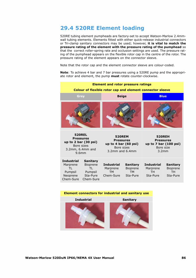
Watson-Marlow 520DuN IP66/NEMA 4X User Manual 86
29.4 520RE Element loading520RE tubing element pumpheads are factory-set to accept Watson-Marlow 2.4mm-wall tubing elements. Elements fitted with either quick-release industrial connectorsor Tri-clamp sanitary connectors may be used; however, it is vital to match thepressure rating of the element with the pressure rating of the pumphead sothat the correct roller-spring rate and occlusion settings are used. The pressure rat-ing of the pumphead appears on the flexible rotor cap in the centre of the rotor. Thepressure rating of the element appears on the connector sleeve.
Note that the rotor cap and the element connector sleeve are colour-coded.
Note: To achieve 4 bar and 7 bar pressures using a 520RE pump and the appropri-ate rotor and element, the pump must rotate counter-clockwise.
Element and rotor pressure ratings
Colour of flexible rotor cap and element connector sleeve
Grey Beige Blue
520RELPressures
up to 2 bar (30 psi)Bore sizes
3.2mm, 6.4mm and9.6mm
520REMPressures
up to 4 bar (60 psi)Bore sizes
3.2mm and 6.4mm
520REHPressures
up to 7 bar (100 psi)Bore size3.2mm
IndustrialMarprene
TLPumpsil
NeopreneChem-Sure
SanitaryBioprene
TLPumpsilSta-Pure
Chem-Sure
IndustrialMarprene
TMChem-Sure
SanitaryBioprene
TMSta-Pure
IndustrialMarprene
THSta-Pure
SanitaryBioprene
THSta-Pure
Element connectors for industrial and sanitary use
Industrial Sanitary
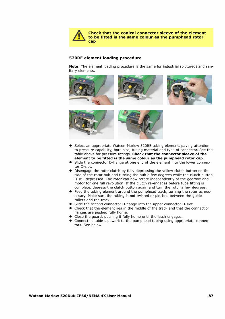
Watson-Marlow 520DuN IP66/NEMA 4X User Manual 87
Check that the conical connector sleeve of the elementto be fitted is the same colour as the pumphead rotorcap
520RE element loading procedure
Note: The element loading procedure is the same for industrial (pictured) and san-itary elements.
� Select an appropriate Watson-Marlow 520RE tubing element, paying attentionto pressure capability, bore size, tubing material and type of connector. See thetable above for pressure ratings. Check that the connector sleeve of theelement to be fitted is the same colour as the pumphead rotor cap.
� Slide the connector D-flange at one end of the element into the lower connec-tor D-slot.
� Disengage the rotor clutch by fully depressing the yellow clutch button on theside of the rotor hub and turning the hub a few degrees while the clutch buttonis still depressed. The rotor can now rotate independently of the gearbox andmotor for one full revolution. If the clutch re-engages before tube fitting iscomplete, depress the clutch button again and turn the rotor a few degrees.
� Feed the tubing element around the pumphead track, turning the rotor as nec-essary. Make sure the tubing is not twisted or pinched between the guiderollers and the track.
� Slide the second connector D-flange into the upper connector D-slot.� Check that the element lies in the middle of the track and that the connectior
flanges are pushed fully home.� Close the guard, pushing it fully home until the latch engages.� Connect suitable pipework to the pumphead tubing using appropriate connec-
tors. See below.
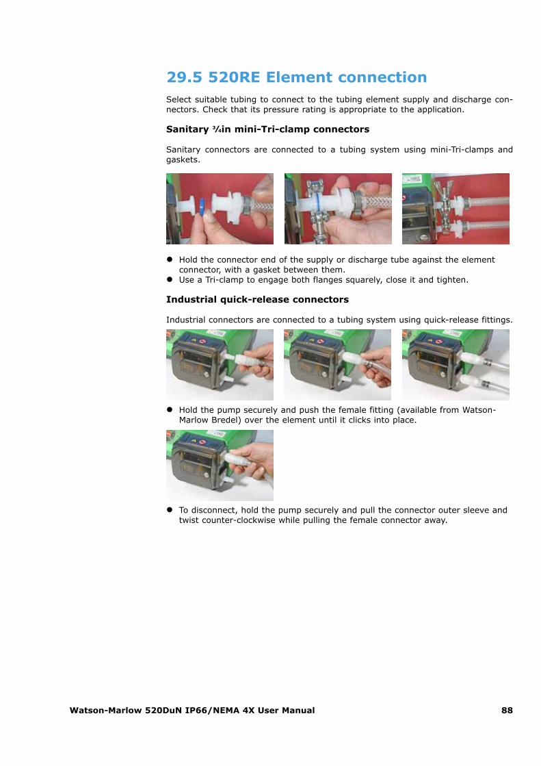
Watson-Marlow 520DuN IP66/NEMA 4X User Manual 88
29.5 520RE Element connectionSelect suitable tubing to connect to the tubing element supply and discharge con-nectors. Check that its pressure rating is appropriate to the application.
Sanitary 3⁄4in mini-Tri-clamp connectors
Sanitary connectors are connected to a tubing system using mini-Tri-clamps andgaskets.
� Hold the connector end of the supply or discharge tube against the elementconnector, with a gasket between them.
� Use a Tri-clamp to engage both flanges squarely, close it and tighten.
Industrial quick-release connectors
Industrial connectors are connected to a tubing system using quick-release fittings.
� Hold the pump securely and push the female fitting (available from Watson-Marlow Bredel) over the element until it clicks into place.
� To disconnect, hold the pump securely and pull the connector outer sleeve andtwist counter-clockwise while pulling the female connector away.
Watson-Marlow 520DuN IP66/NEMA 4X User Manual 89
30 520R, 520R2 and 520REmaintenance
� As part of regular cleaning and maintenance (and at least every three months),lubricate the pivot points, the follower rollers and the tube guide rollers withUltra Lube (PA 1240), which is a non-toxic perfluoroether-based grease.
� The stainless steel pumping rollers run on externally-sealed bearings and arelubricated for life.
� Check that the pumphead track, rotor, rollers and spring-loaded tube clamps (iffitted) are clean and operating properly.
� If fluid is spilled inside the pumphead it should be cleaned as soon as possible,as reducing exposure time to contamination will prolong pumphead service life.
� To clean the pumphead, remove the rotor as described under Rotor removal,above. Flush the pumphead out with water and mild detergent, or suitablecleaning agent. Clean the rotor and rollers in the same way. If specific cleaningagents are required to clean the spillage, consult the general guide to cleaningwith solvents below or Watson-Marlow after-sales office before proceeding, inorder to confirm chemical compatibility. Note: the pumphead guard, rotor capand clutch boot should be removed in advance of some cleaning regimes. Seethe table below. These components are available as spares if damaged.
� Replace the rotor as described under Rotor replacement, above.
Always isolate the pump from the mains power supplybefore opening the guard or performing any positioning,removal or maintenance activity.
Watson-Marlow 520DuN IP66/NEMA 4X User Manual 90
General guide to cleaning with solvents
31 520R, 520R2 and 520RE rotorsettings
520R, 520R2 and 520RE pumpheads are factory-set to give optimum tube life withWatson-Marlow tubing and elements. Radial roller positions should not be adjustedin any circumstances as this will adversely affect pumphead performance and inval-idate warranty. Tamper-proof rotor arm occlusion setting screws are fitted to warnoperators from occlusion adjustment. Tubing with a wall thickness other than 1.6mmor 2.4mm can be used only with a pumphead set up for that purpose during manu-facture. Contact Watson-Marlow after-sales.
Chemical Cleaning precautions
Aliphatic hydrocarbons
Remove guard. Minimize rotor cap and clutchboot exposure to less than one minute(risk of attack).Re-lubricate follower and tube guide rollers.
Aromatic hydrocarbons
Remove guard. Minimize rotor cap and clutchboot exposure to less than one minute(risk of attack).Re-lubricate follower and tube guide rollers.
Ketone solvents
Remove guard. Minimize rotor cap and clutchboot exposure to less than one minute(risk of attack).Re-lubricate follower and tube guide rollers.
Halogenated/chlorinatedsolvents
Not recommended: possible risk topolycarbonate tube clamp adjusters andpolypropylene tube clamp locators.
Alcohols, generalNo precaution necessary.Re-lubricate follower and tube guide rollers.
GlycolsMinimize rotor cap and clutch boot exposure toless than one minute (risk of attack).Re-lubricate follower and tube guide rollers.
Ester solvents
Remove guard. Minimize rotor cap and tubeclamp location cap exposure to less than oneminute (risk of attack).Re-lubricate follower and tube guide rollers.
Ether solventsNot recommended: possible risk topolycarbonate tube clamp adjusters andpolypropylene tube clamp locators.
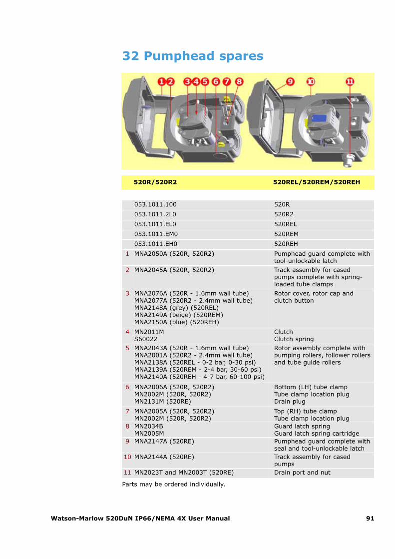
Watson-Marlow 520DuN IP66/NEMA 4X User Manual 91
32 Pumphead spares
Parts may be ordered individually.
053.1011.100 520R
053.1011.2L0 520R2
053.1011.EL0 520REL
053.1011.EM0 520REM
053.1011.EH0 520REH
1 MNA2050A (520R, 520R2) Pumphead guard complete withtool-unlockable latch
2 MNA2045A (520R, 520R2) Track assembly for casedpumps complete with spring-loaded tube clamps
3 MNA2076A (520R - 1.6mm wall tube)MNA2077A (520R2 - 2.4mm wall tube)MNA2148A (grey) (520REL)MNA2149A (beige) (520REM)MNA2150A (blue) (520REH)
Rotor cover, rotor cap andclutch button
4 MN2011MS60022
ClutchClutch spring
5 MNA2043A (520R - 1.6mm wall tube)MNA2001A (520R2 - 2.4mm wall tube)MNA2138A (520REL - 0-2 bar, 0-30 psi)MNA2139A (520REM - 2-4 bar, 30-60 psi)MNA2140A (520REH - 4-7 bar, 60-100 psi)
Rotor assembly complete withpumping rollers, follower rollersand tube guide rollers
6 MNA2006A (520R, 520R2)MN2002M (520R, 520R2)MN2131M (520RE)
Bottom (LH) tube clampTube clamp location plugDrain plug
7 MNA2005A (520R, 520R2)MN2002M (520R, 520R2)
Top (RH) tube clampTube clamp location plug
8 MN2034BMN2005M
Guard latch springGuard latch spring cartridge
9 MNA2147A (520RE) Pumphead guard complete withseal and tool-unlockable latch
10 MNA2144A (520RE) Track assembly for casedpumps
11 MN2023T and MN2003T (520RE) Drain port and nut
520R/520R2 520REL/520REM/520REH
Watson-Marlow 520DuN IP66/NEMA 4X User Manual 92
33 Flow ratesPumping conditions
For precise and repeatable performance it is important to determine flowrates under operating conditions for each new piece of tubing.
When rotating counter-clockwise, 520R, 520R2 and 520RE pumpheads’flow rates are directly proportional to rotor speed. When rotating clock-wise, 520R, 520R2 and 520RE pumpheads’ flow rates are directly propor-tional to rotor speed up to 1.5 bar; their performance above 1.5 bar shouldbe determined empirically.
Note: 520RE pumpheads should be used rotating counter-clockwise if pres-sures above 1.5 bar are required.
If you wish to run the pump at a speed not shown in the tables below, flowfigures can be reached by dividing the maximum flow shown in the tablesbelow by the maximum rpm figure, and multiplying the result by yourrequired speed in rpm.
Actual flow rates achieved may vary because of changes in temperature, viscosity,inlet and discharge pressures, system configuration and tubing performance againsttime. Flow rates may also vary due to normal manufacturing tolerances of the tub-ing. These tolerances will make flow rate variance more pronounced at smaller boresizes.
520R and 520R2
All performance figures for the 520R and 520R2 pumpheads have been recordedagainst peak pipeline pressures.
Although rated to 2bar (30psi) peak pressure, this pump will generate in excess of2bar (30psi) peak pressure if the pipeline is restricted. Where it is important that2bar (30psi) is not exceeded, pressure relief valves should be installed in thepipeline.
Viscosity handling is maximised by using 2.4mm wall tubing with the 520R2 pumphead.
Flow rates are normalised test values obtained using 225mm (8 7⁄8 in) of new tubing(measured from the inside faces of the tube clamps), and the pumphead rotatingclockwise pumping water at 20C with negligible inlet and discharge pressures.
Note: Flow rates quoted are for 1.6mm and 2.4mm wall tubes. Tubes of 0.5mm and0.8mm bore are only available in 1.6mm wall thickness except for platinum-curedsilicone. Tubes of 9.6mm bore are only available in 2.4mm wall thickness.
Watson-Marlow 520DuN IP66/NEMA 4X User Manual 93
520RE
Performance figures for the 520REL and 520REM have been recorded against 2barpeak pressure and 4bar peak pressure respectively.
Performance figures for the 520REH have been recorded against 7bar constant pressure.
Although the 520REL is rated to 2bar (30psi) peak pressure, the 520REM is rated to4bar (60psi) peak pressure and the 520REH is rated to 7bar (100psi) constant pres-sure, the pumps will generate in excess of these pressures if the system pressuresexceed this. Where it is important that these rated pressures are not exceeded,pressure relief valves should be installed in the pipeline.
Flow rates are normalised test values obtained using 520 elements and the pump-head rotating anticlockwise pumping water at 20C with negligible inlet and dischargepressures.
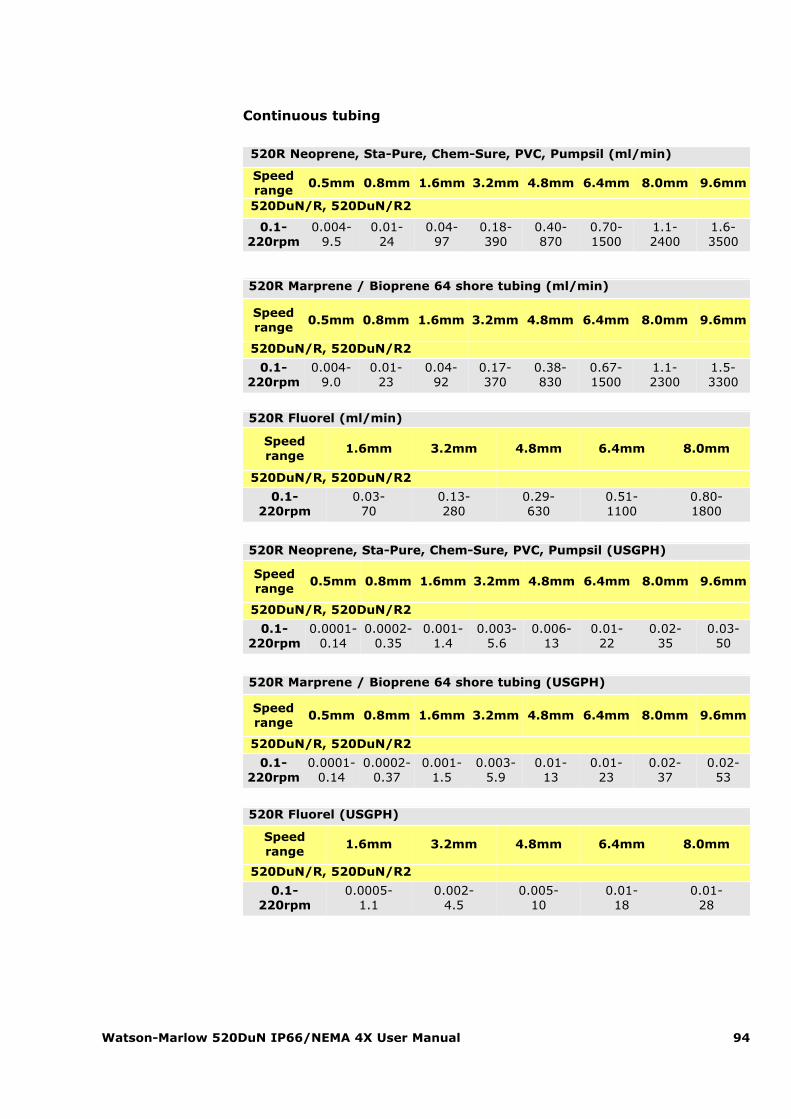
Watson-Marlow 520DuN IP66/NEMA 4X User Manual 94
520R Fluorel (ml/min)
Speedrange
1.6mm 3.2mm 4.8mm 6.4mm 8.0mm
520DuN/R, 520DuN/R2
0.1-220rpm
0.03-70
0.13-280
0.29-630
0.51-1100
0.80-1800
520R Fluorel (USGPH)
Speedrange
1.6mm 3.2mm 4.8mm 6.4mm 8.0mm
520DuN/R, 520DuN/R2
0.1-220rpm
0.0005-1.1
0.002-4.5
0.005-10
0.01-18
0.01-28
520R Neoprene, Sta-Pure, Chem-Sure, PVC, Pumpsil (USGPH)
Speedrange
0.5mm 0.8mm 1.6mm 3.2mm 4.8mm 6.4mm 8.0mm 9.6mm
520DuN/R, 520DuN/R2
0.1-220rpm
0.0001-0.14
0.0002-0.35
0.001-1.4
0.003-5.6
0.006-13
0.01-22
0.02-35
0.03-50
520R Marprene / Bioprene 64 shore tubing (USGPH)
Speedrange
0.5mm 0.8mm 1.6mm 3.2mm 4.8mm 6.4mm 8.0mm 9.6mm
520DuN/R, 520DuN/R2
0.1-220rpm
0.0001-0.14
0.0002-0.37
0.001-1.5
0.003-5.9
0.01-13
0.01-23
0.02-37
0.02-53
520R Neoprene, Sta-Pure, Chem-Sure, PVC, Pumpsil (ml/min)
Speedrange
0.5mm 0.8mm 1.6mm 3.2mm 4.8mm 6.4mm 8.0mm 9.6mm
520DuN/R, 520DuN/R2
0.1-220rpm
0.004-9.5
0.01-24
0.04-97
0.18-390
0.40-870
0.70-1500
1.1-2400
1.6-3500
520R Marprene / Bioprene 64 shore tubing (ml/min)
Speedrange
0.5mm 0.8mm 1.6mm 3.2mm 4.8mm 6.4mm 8.0mm 9.6mm
520DuN/R, 520DuN/R2
0.1-220rpm
0.004-9.0
0.01-23
0.04-92
0.17-370
0.38-830
0.67-1500
1.1-2300
1.5-3300
Continuous tubing
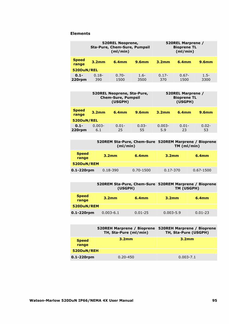
Elements
Watson-Marlow 520DuN IP66/NEMA 4X User Manual 95
520REL Neoprene, Sta-Pure, Chem-Sure, Pumpsil
(ml/min)
520REL Marprene / Bioprene TL
(ml/min)
Speedrange
3.2mm 6.4mm 9.6mm 3.2mm 6.4mm 9.6mm
520DuN/REL
0.1-220rpm
0.18-390
0.70-1500
1.6-3500
0.17-370
0.67-1500
1.5-3300
520REM Sta-Pure, Chem-Sure(ml/min)
520REM Marprene / BiopreneTM (ml/min)
Speedrange
3.2mm 6.4mm 3.2mm 6.4mm
520DuN/REM
0.1-220rpm 0.18-390 0.70-1500 0.17-370 0.67-1500
520REM Sta-Pure, Chem-Sure(USGPH)
520REM Marprene / BiopreneTM (USGPH)
Speedrange
3.2mm 6.4mm 3.2mm 6.4mm
520DuN/REM
0.1-220rpm 0.003-6.1 0.01-25 0.003-5.9 0.01-23
520REH Marprene / BiopreneTH, Sta-Pure (ml/min)
520REH Marprene / BiopreneTH, Sta-Pure (USGPH)
Speedrange
3.2mm 3.2mm
520DuN/REH
0.1-220rpm 0.20-450 0.003-7.1
520REL Neoprene, Sta-Pure,Chem-Sure, Pumpsil
(USGPH)
520REL Marprene / Bioprene TL
(USGPH)
Speedrange
3.2mm 6.4mm 9.6mm 3.2mm 6.4mm 9.6mm
520DuN/REL
0.1-220rpm
0.003-6.1
0.01-25
0.03-55
0.003-5.9
0.01-23
0.02-53
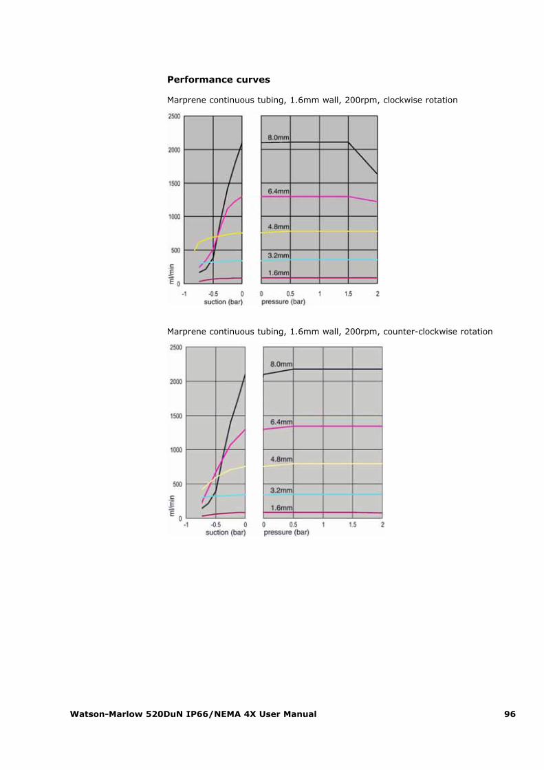
Watson-Marlow 520DuN IP66/NEMA 4X User Manual 96
Performance curves
Marprene continuous tubing, 1.6mm wall, 200rpm, clockwise rotation
Marprene continuous tubing, 1.6mm wall, 200rpm, counter-clockwise rotation
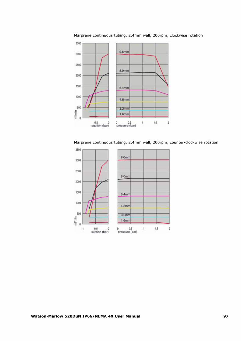
Watson-Marlow 520DuN IP66/NEMA 4X User Manual 97
Marprene continuous tubing, 2.4mm wall, 200rpm, clockwise rotation
Marprene continuous tubing, 2.4mm wall, 200rpm, counter-clockwise rotation
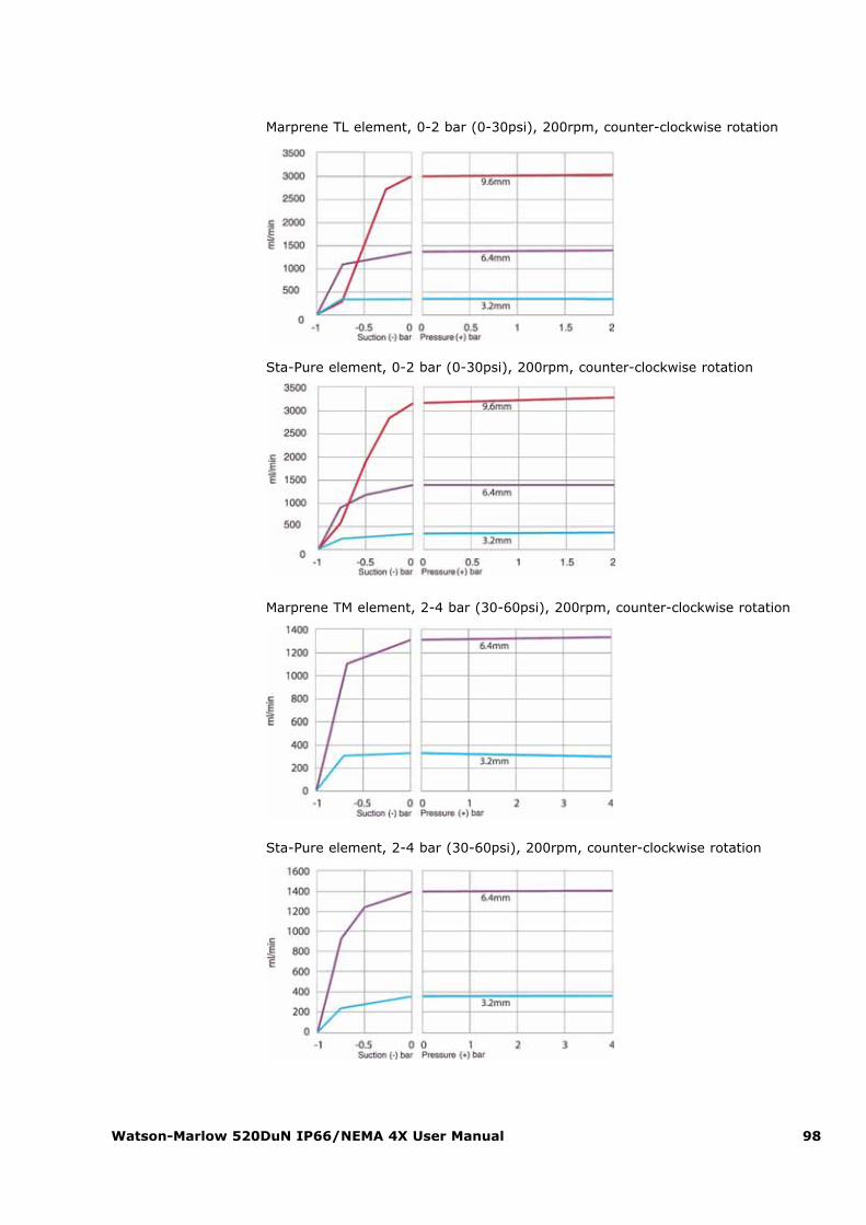
Watson-Marlow 520DuN IP66/NEMA 4X User Manual 98
Marprene TL element, 0-2 bar (0-30psi), 200rpm, counter-clockwise rotation
Sta-Pure element, 0-2 bar (0-30psi), 200rpm, counter-clockwise rotation
Marprene TM element, 2-4 bar (30-60psi), 200rpm, counter-clockwise rotation
Sta-Pure element, 2-4 bar (30-60psi), 200rpm, counter-clockwise rotation
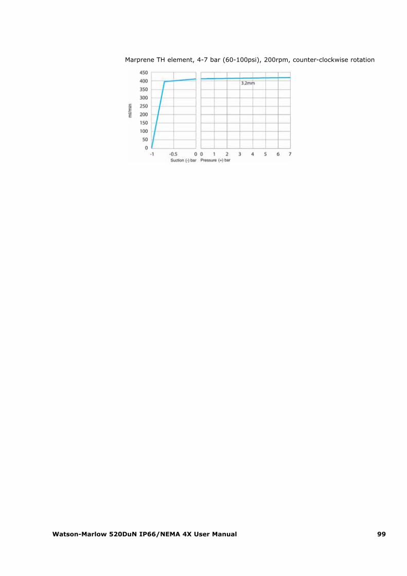
Watson-Marlow 520DuN IP66/NEMA 4X User Manual 99
Marprene TH element, 4-7 bar (60-100psi), 200rpm, counter-clockwise rotation
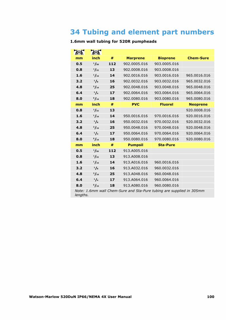
Watson-Marlow 520DuN IP66/NEMA 4X User Manual 100
34 Tubing and element part numbers1.6mm wall tubing for 520R pumpheads
mm inch # Marprene Bioprene Chem-Sure
0.5 1/50 112 902.0005.016 903.0005.016
0.8 1/32 13 902.0008.016 903.0008.016
1.6 1/16 14 902.0016.016 903.0016.016 965.0016.016
3.2 1/8 16 902.0032.016 903.0032.016 965.0032.016
4.8 3/16 25 902.0048.016 903.0048.016 965.0048.016
6.4 1/4 17 902.0064.016 903.0064.016 965.0064.016
8.0 5/16 18 902.0080.016 903.0080.016 965.0080.016
mm inch # PVC Fluorel Neoprene
0.8 1/32 13 920.0008.016
1.6 1/16 14 950.0016.016 970.0016.016 920.0016.016
3.2 1/8 16 950.0032.016 970.0032.016 920.0032.016
4.8 3/16 25 950.0048.016 970.0048.016 920.0048.016
6.4 1/4 17 950.0064.016 970.0064.016 920.0064.016
8.0 5/16 18 950.0080.016 970.0080.016 920.0080.016
mm inch # Pumpsil Sta-Pure
0.5 1/50 112 913.A005.016
0.8 1/32 13 913.A008.016
1.6 1/16 14 913.A016.016 960.0016.016
3.2 1/8 16 913.A032.016 960.0032.016
4.8 3/16 25 913.A048.016 960.0048.016
6.4 1/4 17 913.A064.016 960.0064.016
8.0 5/16 18 913.A080.016 960.0080.016
Note: 1.6mm wall Chem-Sure and Sta-Pure tubing are supplied in 305mmlengths.

Watson-Marlow 520DuN IP66/NEMA 4X User Manual 101
2.4mm wall tubing for 520R2 pumpheads
mm inch # Marprene Bioprene Pumpsil
0.5 1/50 913.A005.024
0.8 1/32 913.A008.024
1.6 1/16 119 902.0016.024 903.0016.024 913.A016.024
3.2 1/8 120 902.0032.024 903.0032.024 913.A032.024
4.8 3/16 15 902.0048.024 903.0048.024 913.A048.024
6.4 1/4 24 902.0064.024 903.0064.024 913.A064.024
8.0 5/16 121 902.0080.024 903.0080.024 913.A080.024
9.6 3/8 122 902.0096.024 903.0096.024 913.A096.024
mm inch # Chem-Sure Sta-Pure
0.8 1/32
1.6 1/16 119 965.0016.024 960.0016.024
3.2 1/8 120 965.0032.024 960.0032.024
4.8 3/16 15 965.0048.024 960.0048.024
6.4 1/4 24 965.0064.024 960.0064.024
8.0 5/16 121 965.0080.024 960.0080.024Note: 2.4mm wall Chem-Sure and Sta-Pure tubing are supplied in 355mmlengths.
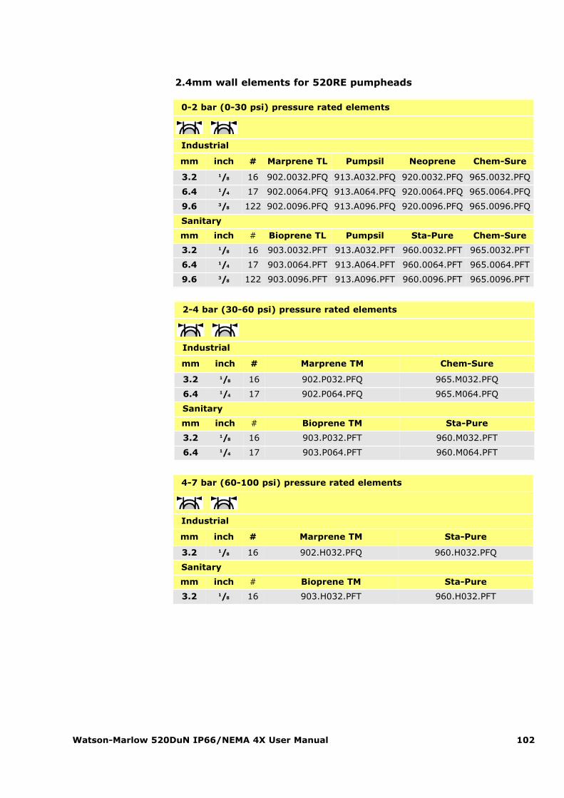
Watson-Marlow 520DuN IP66/NEMA 4X User Manual 102
2.4mm wall elements for 520RE pumpheads
0-2 bar (0-30 psi) pressure rated elements
Industrial
mm inch # Marprene TL Pumpsil Neoprene Chem-Sure
3.2 1/8 16 902.0032.PFQ 913.A032.PFQ 920.0032.PFQ 965.0032.PFQ
6.4 1/4 17 902.0064.PFQ 913.A064.PFQ 920.0064.PFQ 965.0064.PFQ
9.6 3/8 122 902.0096.PFQ 913.A096.PFQ 920.0096.PFQ 965.0096.PFQ
Sanitary
mm inch # Bioprene TL Pumpsil Sta-Pure Chem-Sure
3.2 1/8 16 903.0032.PFT 913.A032.PFT 960.0032.PFT 965.0032.PFT
6.4 1/4 17 903.0064.PFT 913.A064.PFT 960.0064.PFT 965.0064.PFT
9.6 3/8 122 903.0096.PFT 913.A096.PFT 960.0096.PFT 965.0096.PFT
2-4 bar (30-60 psi) pressure rated elements
Industrial
mm inch # Marprene TM Chem-Sure
3.2 1/8 16 902.P032.PFQ 965.M032.PFQ
6.4 1/4 17 902.P064.PFQ 965.M064.PFQ
Sanitary
mm inch # Bioprene TM Sta-Pure
3.2 1/8 16 903.P032.PFT 960.M032.PFT
6.4 1/4 17 903.P064.PFT 960.M064.PFT
4-7 bar (60-100 psi) pressure rated elements
Industrial
mm inch # Marprene TM Sta-Pure
3.2 1/8 16 902.H032.PFQ 960.H032.PFQ
Sanitary
mm inch # Bioprene TM Sta-Pure
3.2 1/8 16 903.H032.PFT 960.H032.PFT
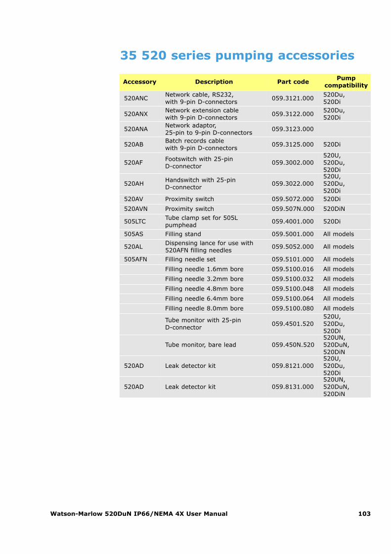
Watson-Marlow 520DuN IP66/NEMA 4X User Manual 103
35 520 series pumping accessories
Accessory Description Part codePump
compatibility
520ANCNetwork cable, RS232, with 9-pin D-connectors
059.3121.000520Du, 520Di
520ANXNetwork extension cable with 9-pin D-connectors
059.3122.000520Du, 520Di
520ANANetwork adaptor, 25-pin to 9-pin D-connectors
059.3123.000
520ABBatch records cable with 9-pin D-connectors
059.3125.000 520Di
520AFFootswitch with 25-pin D-connector
059.3002.000520U, 520Du, 520Di
520AHHandswitch with 25-pin D-connector
059.3022.000520U, 520Du, 520Di
520AV Proximity switch 059.5072.000 520Di
520AVN Proximity switch 059.507N.000 520DiN
505LTCTube clamp set for 505Lpumphead
059.4001.000 520Di
505AS Filling stand 059.5001.000 All models
520ALDispensing lance for use with520AFN filling needles
059.5052.000 All models
505AFN Filling needle set 059.5101.000 All models
Filling needle 1.6mm bore 059.5100.016 All models
Filling needle 3.2mm bore 059.5100.032 All models
Filling needle 4.8mm bore 059.5100.048 All models
Filling needle 6.4mm bore 059.5100.064 All models
Filling needle 8.0mm bore 059.5100.080 All models
Tube monitor with 25-pin D-connector
059.4501.520520U, 520Du, 520Di
Tube monitor, bare lead 059.450N.520520UN,520DuN,520DiN
520AD Leak detector kit 059.8121.000520U, 520Du, 520Di
520AD Leak detector kit 059.8131.000520UN,520DuN,520DiN
Watson-Marlow 520DuN IP66/NEMA 4X User Manual 104
36 TrademarksWatson-Marlow, Bioprene, Pumpsil, LoadSure and Marprene are trademarksof Watson-Marlow Limited.
Fluorel is a trademark of 3M.
Sta-Pure and Chem-Sure are trademarks of W.L.Gore and Associates.
37 Warning not to use pumps inpatient-connected applicationsWarning These products are not designed for use in, and should not be used forpatient-connected applications.
38 Publication historym-520dun-4x-gb-05.qxp: Watson-Marlow 520DuN IP66 NEMA 4X
First published 12 03. Revised 09 06. Revised 01 08.
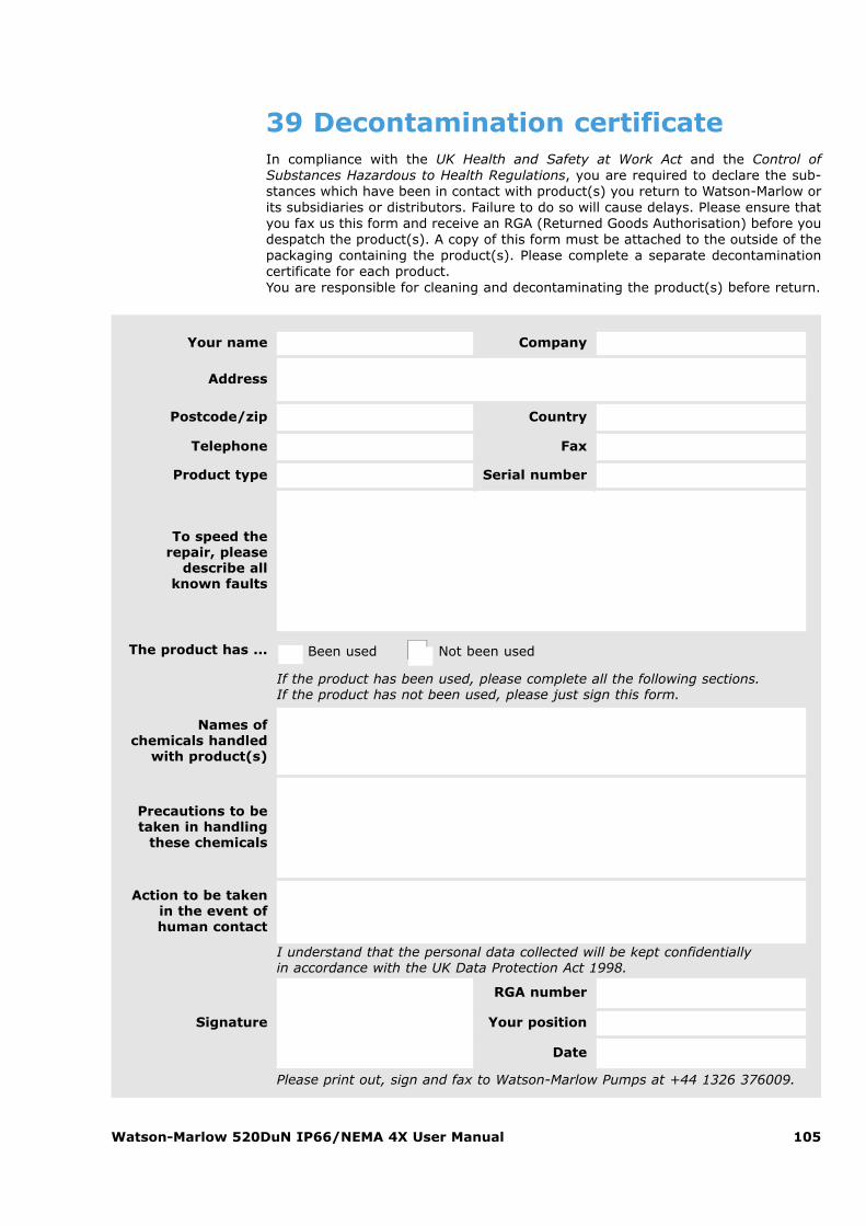
Watson-Marlow 520DuN IP66/NEMA 4X User Manual 105
39 Decontamination certificateIn compliance with the UK Health and Safety at Work Act and the Control ofSubstances Hazardous to Health Regulations, you are required to declare the sub-stances which have been in contact with product(s) you return to Watson-Marlow orits subsidiaries or distributors. Failure to do so will cause delays. Please ensure thatyou fax us this form and receive an RGA (Returned Goods Authorisation) before youdespatch the product(s). A copy of this form must be attached to the outside of thepackaging containing the product(s). Please complete a separate decontaminationcertificate for each product.You are responsible for cleaning and decontaminating the product(s) before return.
Your name Company
Address
Postcode/zip Country
Telephone Fax
Product type Serial number
To speed therepair, please
describe all known faults
The product has ... � Been used �� Not been used
If the product has been used, please complete all the following sections. If the product has not been used, please just sign this form.
Names of chemicals handled
with product(s)
Precautions to betaken in handling
these chemicals
Action to be takenin the event ofhuman contact
I understand that the personal data collected will be kept confidentially in accordance with the UK Data Protection Act 1998.
RGA number
Signature Your position
Date
Please print out, sign and fax to Watson-Marlow Pumps at +44 1326 376009.