Watson 5 Manual - "Schmid Watson HDSL ve EFM … · Watson TDM Operating Manual...
130
Watson TDM Operating Manual Document Identification Watson-TDM-Manual-W.doc Document Version 2.0-01 Document Revision 2008-02-07 Distribution Customer
Transcript of Watson 5 Manual - "Schmid Watson HDSL ve EFM … · Watson TDM Operating Manual...
Watson TDM Operating Manual
Document Identification Watson-TDM-Manual-W.doc Document Version 2.0-01 Document Revision 2008-02-07 Distribution Customer
Watson TDM
Operating Manual
Watson-TDM-Manual-W.doc Version 2.0-01
ii Revision: 2008-02-07
Revision History
Revision Date Author Remarks 2.0-01 080207 RBt Update for Plug-in FW 4.1 1.2-01 071221 RBt Added information about MTBF Values, PSB command 1.1-01 070924 RBt Editorial changes 1.0-01 070523 RBt Initial version
Copyright 2008 by Schmid Telecommunication, Zurich, Switzerland. All rights reserved. Reproduction of part or all of the contents in any form is expressly prohibited without the prior written consent of Schmid Telecommunication. Schmid Telecommunication has used its discretion, best judgments and efforts in preparing this document. Any in-formation contained in this document is provided without any warranty of any kind. Schmid Telecommunication hereby disclaims any liability to any person for any kind of damage. Schmid Telecommunication may make improve-ments and/or changes of this document at any time.

Revision: 2008-02-07 i
Declaration of Conformity
Tabletop Watson TDM tabletop 1p E1 120 Ohm SZ.847.V310 Watson TDM tabletop 1p nx64, E1 120 Ohm SZ.847.V318 Watson TDM tabletop 1p E1 75 Ohm SZ.847.V330 Watson TDM tabletop 1p nx64, E1 75 Ohm SZ.847.V338 Watson TDM tabletop 2p E1 120 Ohm SZ.847.V410 Watson TDM tabletop 2p nx64, E1 120 Ohm SZ.847.V418 Watson TDM tabletop 2p E1 75 Ohm SZ.847.V430 Watson TDM tabletop 2p nx64, E1 75 Ohm SZ.847.V438 Plug-in Watson TDM plug-in 4xDSL 2xE1 120 Ohm SZ.867.V612 Watson TDM plug-in 4xDSL 4xE1 120 Ohm SZ.867.V614 Watson TDM plug-in 4xDSL 2xE1 75 Ohm SZ.867.V632 Watson TDM plug-in 4xDSL 4xE1 75 Ohm SZ.867.V634 Watson TDM plug-in 4xDSL 2xnx64 SZ.867.V682 Watson TDM plug-in 2xDSL nx64 E1 120 Ohm SZ.867.V218 Watson TDM plug-in 2xDSL nx64 E1 75 Ohm SZ.867.V238 Watson TDM plug-in 2xDSL nx64 E1 120 Ohm SZ.867.V218 Regenerator Regenerator Watson TDM and Watson 5 SZ.856.V310 Regenerator Watson TDM and Watson 5 SZ.856.V311 Regenerator Watson TDM and Watson 5 SZ.856.V410
Manufacturer: Schmid Telecom AG, Binzstrasse 35, CH-8045 Zurich
Watson TDM
Operating Manual
Watson-TDM-Manual-W.doc Version 2.0-01
ii Revision: 2008-02-07
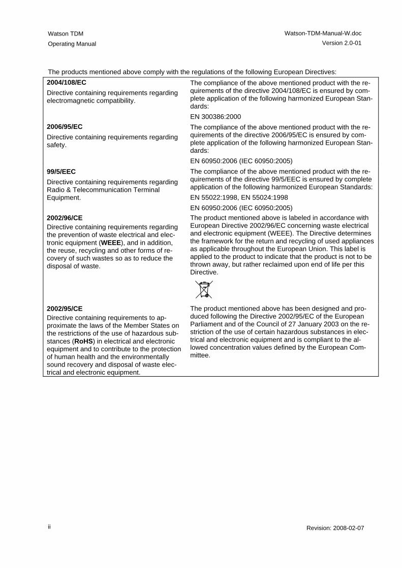
The products mentioned above comply with the regulations of the following European Directives: 2004/108/EC Directive containing requirements regarding electromagnetic compatibility.
The compliance of the above mentioned product with the re-quirements of the directive 2004/108/EC is ensured by com-plete application of the following harmonized European Stan-dards: EN 300386:2000
2006/95/EC Directive containing requirements regarding safety.
The compliance of the above mentioned product with the re-quirements of the directive 2006/95/EC is ensured by com-plete application of the following harmonized European Stan-dards: EN 60950:2006 (IEC 60950:2005)
99/5/EEC Directive containing requirements regarding Radio & Telecommunication Terminal Equipment.
The compliance of the above mentioned product with the re-quirements of the directive 99/5/EEC is ensured by complete application of the following harmonized European Standards: EN 55022:1998, EN 55024:1998 EN 60950:2006 (IEC 60950:2005)
2002/96/CE Directive containing requirements regarding the prevention of waste electrical and elec-tronic equipment (WEEE), and in addition, the reuse, recycling and other forms of re-covery of such wastes so as to reduce the disposal of waste.
The product mentioned above is labeled in accordance with European Directive 2002/96/EC concerning waste electrical and electronic equipment (WEEE). The Directive determines the framework for the return and recycling of used appliances as applicable throughout the European Union. This label is applied to the product to indicate that the product is not to be thrown away, but rather reclaimed upon end of life per this Directive.
2002/95/CE Directive containing requirements to ap-proximate the laws of the Member States on the restrictions of the use of hazardous sub-stances (RoHS) in electrical and electronic equipment and to contribute to the protection of human health and the environmentally sound recovery and disposal of waste elec-trical and electronic equipment.
The product mentioned above has been designed and pro-duced following the Directive 2002/95/EC of the European Parliament and of the Council of 27 January 2003 on the re-striction of the use of certain hazardous substances in elec-trical and electronic equipment and is compliant to the al-lowed concentration values defined by the European Com-mittee.
Watson-TDM-Manual-W.doc
Version 2.0-01
Watson TDM Operating Manual
Revision: 2008-02-07 iii
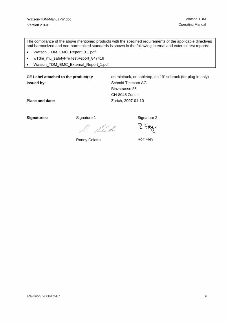
The compliance of the above mentioned products with the specified requirements of the applicable directives and harmonized and non-harmonized standards is shown in the following internal and external test reports: • Watson_TDM_EMC_Report_0.1.pdf • wTdm_ntu_safetyPreTestReport_847418 • Watson_TDM_EMC_External_Report_1.pdf CE Label attached to the product(s): on minirack, on tabletop, on 19” subrack (for plug-in only) Issued by: Schmid Telecom AG
Binzstrasse 35 CH-8045 Zurich
Place and date:
Zurich, 2007-01-10
Signatures: Signature 1
Ronny Colotto
Signature 2
Rolf Frey


Revision: 2008-02-07 v
Important Safety Precautions
To reduce the risk of fire, bodily injury, and damage to the equipment the follow-ing precautions must be observed: • Read and follow all warning notices and instructions marked on the product or
included in the manual. • Installation of this equipment has to be done by qualified personnel only. • To achieve safety and satisfactory EMC performance, the plug-in boards
have to be inserted into appropriate subracks. Subrack slots that are not used must covered with a blanking plate.
• The subracks must be connected to earth. This is achieved by installing the subracks into properly grounded rack or by connecting the protective ground terminal provided on some subracks to the earthing network.
• If the subracks are installed in racks then these racks must be connected to the earthing network according to ETS 300 253.
• Where protective ground terminals are available on subracks these terminals are marked with the symbol . The following rules must be observed: - The earthing network must be connected to the protective ground terminal
continuously and securely. - Where the subracks are fitted with an AC power connector the earthing
network must be connected securely to the protective ground terminal even if the AC power cord is disconnected from the subracks.
- The protective grounding may only be disconnected from the subracks af-ter the DSL line has been disconnected from the plug-in.
• This product is to be used with telecommunications circuits. Take the follow-ing precautions: - Never install telephone wiring during a lightning storm. - Never install telephone jacks in wet locations unless the jack is specifi-
cally designed for wet locations. - Never touch uninsulated telephone wires or terminals unless the tele-
phone line has been disconnected at the network interface. - Use caution when installing or modifying telephone lines. - Avoid using a telephone (other than a cordless type) during an electrical
storm. There may be a remote risk of electric shock from lightning. - Do not use the telephone to report a gas leak in the vicinity of the leak.
• Condensation may occur externally or internally if this product is moved from a colder room to a warmer room. When moving this product under such con-ditions, allow ample time for this product to reach room temperature and to dry before operating.
• This product is intended for use in environments as stated in the technical specifications. Do not use this product in areas classified as hazardous loca-tions. Such areas include patient care areas of medical and dental facilities,

Watson TDM
Operating Manual
Watson-TDM-Manual-W.doc Version 2.0-01
vi Revision: 2008-02-07
oxygen-laden environments, or industrial facilities. Contact your local electri-cal authority governing building construction, maintenance, or safety for more information regarding the installation of this product.
• Slots and openings in this product are provided for ventilation and should never be blocked or covered, since these ensure reliable operation of this product and protect it from overheating. This product should not be placed in a built-in apparatus such as a rack unless the apparatus has been specifically designed to accommodate the product, proper ventilation is provided for the product, and the product instructions have been followed.
• This product should be placed away from radiators, heat registers, stoves, or other pieces of equipment that produce heat. Allow sufficient air circulation around the product and the AC adapter during use to ensure adequate cool-ing of the device.
• Do not use this product in a wet location. • Normal operation of this product is only possible when the external housing is
left in place. • This product should be operated only from the type of power source indicated
on the product's electrical ratings label. If you have questions about the type of power source to use, contact your local Schmid Distributor or local power company.
• Be sure that the power outlet you plug the power cord into is easily accessible and located as close to the equipment operator as possible. When you need to disconnect power to this product, be sure to unplug the power cord from the electrical outlet.
• Ensure that the voltage select switch, if provided on this product, is in the cor-rect position for the type of voltage in your country (115 VAC or 230 VAC).
• Do not allow anything to rest on any of the attached cables and do not posi-tion this product where persons will walk or trip on the cables.
• Unplug this product from the wall outlet before cleaning. Do not use liquid cleaners or aerosol cleaners. Use a damp cloth for cleaning.
• Never push a foreign object through an opening in this product. • Unplug the product from the electrical outlet and contact your local Schmid
Distributor under the following conditions: - The power cord, extension cord, or plug is damaged. - Liquid has been spilled or an object has fallen into this product. - This product has been exposed to water. - This product has been dropped or damaged in any way. - There are noticeable signs of overheating. - This product does not operate normally when you follow the operating in-
structions.

Watson-TDM-Manual-W.doc
Version 2.0-01
Watson TDM Operating Manual
Revision: 2008-02-07 vii
• Do not attempt to service this product yourself, as opening or removing cov-ers may expose you to dangerous high voltage points or other risks. Refer all servicing to your local Schmid Distributor.
• Upon completion of any service or repairs to this product, have your local Schmid Distributor perform any safety checks required by the repair proce-dure or by local codes to determine that the product is in proper operating condition.


Revision: 2008-02-07 ix
Limited Product Warranty
Schmid Telecom warrants that for two (2) years from the date of shipment to Customer, all products manufactured by Schmid Telecom will be free from de-fects in materials and workmanship. Schmid Telecom also warrants that products will conform to the applicable specification and drawings for such products, as contained in the Product Manual on in Schmid Telecom internal specifications and drawings for such products (which may or may not be reflected in the Prod-uct Manual). This warranty only applies if Customer gives Schmid Telecom writ-ten notice of defects during the warranty period. Upon such notice, Schmid Tele-com will, at its option, either repair or replace the defective item. If Schmid Telecom is unable, in a reasonable time, to repair or replace any equipment to a condition as warranted, Customers is entitled to a full refund of the purchase price upon return of the equipment to Schmid Telecom. This war-ranty applies only to the original purchaser and is not transferable without Schmid Telecom express written permission. This warranty becomes null and void if Cus-tomer modifies or alters the equipment in any way, other than as specifically au-thorized by Schmid Telecom. Except for the limited warranty described above, the foregoing constitutes the sole and exclusive remedy of the Customer and the exclusive liability of Schmid Telecom and is in Lieu of any and all other warranties (expressed or implied). Schmid Telecom specifically disclaims all other warranties, including (without limitation), all warranties of merchantability and fitness for a particular purpose. Some states do not allow the exclusion of implied warranties, so this exclusion may not apply to Customer. In no event will Schmid Telecom or its suppliers be liable to Customer for any in-cidental, special, punitive, exemplary or consequential damages experienced by either Customer or a third party (including, but not limited to, loss of data or in-formation, loss of profits, or loss of use). Schmid Telecom is not liable for dam-ages for any cause whatsoever (whether based in contract, tort, or otherwise) in excess of the amount paid for the item. Some states do not allow the limitation or exclusion of liability for incidental or consequential damages, so the above limita-tion or exclusion may not apply to Customer.

Revision: 2008-02-07 xi
Table of Contents
1 References ........................................................................................................................ 1-1
2 Watson TDM Overview..................................................................................................... 2-2 2.1 Introduction ............................................................................................................... 2-2 2.2 Modem Features ....................................................................................................... 2-2 2.3 Accessories............................................................................................................... 2-3 2.4 Compatibility with other Watson modems ................................................................. 2-3
3 Watson TDM Features...................................................................................................... 3-1 3.1 DSL Interface ............................................................................................................ 3-1
3.1.1 Master / Slave ................................................................................................ 3-1 3.1.2 Linerates and payload rates........................................................................... 3-1 3.1.3 Multipair operation ......................................................................................... 3-2 3.1.4 DSL Clocking options..................................................................................... 3-3 3.1.5 Power Backoff................................................................................................ 3-4 3.1.6 Wetting Current.............................................................................................. 3-5
3.2 E1 Interface............................................................................................................... 3-5 3.2.1 Framing.......................................................................................................... 3-5 3.2.2 AIS Detection ................................................................................................. 3-6 3.2.3 AIS Generation .............................................................................................. 3-6 3.2.4 E1 Clock Modes............................................................................................. 3-7 3.2.5 High Capacity E1 ........................................................................................... 3-8
3.3 ISDN PRA Interface ................................................................................................ 3-10 3.3.1 CRC4 Processing Options ........................................................................... 3-10 3.3.2 Generation of CRC4 error notifications to the ET ........................................ 3-14
3.4 nx64 kbit/s Interface................................................................................................ 3-15 3.4.1 Features....................................................................................................... 3-15 3.4.2 Handshake Operation .................................................................................. 3-16 3.4.3 Supported V.54 Loops ................................................................................. 3-16 3.4.4 Automatic Loop Control through the DTE/DCE Interface ............................ 3-16 3.4.5 Clock Direction............................................................................................. 3-17 3.4.6 Clock Polarity ............................................................................................... 3-17 3.4.7 Byte Timing .................................................................................................. 3-17 3.4.8 Multiservice / nx64 Clock Modes ................................................................. 3-17
3.5 Timeslot Mapping.................................................................................................... 3-18 3.5.1 E1 mappings ................................................................................................ 3-18 3.5.2 nx64 mappings............................................................................................. 3-19 3.5.3 Multiservice and Mixed Mode mappings...................................................... 3-20
Watson TDM
Operating Manual
Watson-TDM-Manual-W.doc Version 2.0-01
xii Revision: 2008-02-07
3.6 Point-to-Multipoint Operation .................................................................................. 3-21 3.6.1 Introduction .................................................................................................. 3-21 3.6.2 Configuration................................................................................................ 3-22 3.6.3 Multipoint Configuration Example ................................................................ 3-25 3.6.4 Multipoint Cascading.................................................................................... 3-26
3.7 Performance Monitoring.......................................................................................... 3-28 3.7.1 DSL Parameters .......................................................................................... 3-28 3.7.2 G.826 Performance Monitoring.................................................................... 3-28
3.8 Test loops................................................................................................................ 3-30 3.9 Automatic Protection Switching (APS) .................................................................... 3-31 3.10 Password Protection ............................................................................................... 3-32
4 Watson TDM Regenerator ............................................................................................... 4-1 4.1 Operating modes....................................................................................................... 4-1 4.2 Interface Designation ................................................................................................ 4-1 4.3 Cascading ................................................................................................................. 4-2 4.4 Powering ................................................................................................................... 4-2
5 Powering ........................................................................................................................... 5-1 5.1 Plug-in ....................................................................................................................... 5-1 5.2 Tabletop .................................................................................................................... 5-1
5.2.1 Power and Grounding .................................................................................... 5-1 5.3 Remote Powering...................................................................................................... 5-2
5.3.1 Remote power feeding on plug-ins ................................................................ 5-2 5.3.2 Remote powering of Tabletops ..................................................................... 5-3 5.3.3 Powering Status Display ................................................................................ 5-3 5.3.4 Power Failure Alarm ...................................................................................... 5-3 5.3.5 Remote powering reach................................................................................. 5-4
6 LEDs, Alarms .................................................................................................................... 6-1 6.1 Plug-in LEDs ............................................................................................................. 6-1
6.1.1 Plug-in LED mapping ..................................................................................... 6-1 6.1.2 Plug-in LED Indications.................................................................................. 6-1
6.2 Tabletop LEDs .......................................................................................................... 6-2 6.2.1 Tabletop LED mapping .................................................................................. 6-2 6.2.2 Tabletop LED Indications............................................................................... 6-2
6.3 Alarm Conditions....................................................................................................... 6-3 6.4 Alarm Relays............................................................................................................. 6-4 6.5 Initialization Errors..................................................................................................... 6-4
7 The Monitor....................................................................................................................... 7-1 7.1 Introduction ............................................................................................................... 7-1 7.2 Addressing ................................................................................................................ 7-2
7.2.1 Plug-in in subrack .......................................................................................... 7-2 7.2.2 Plug-in in minirack mechanics or tabletop housing........................................ 7-3 7.2.3 Tabletop ......................................................................................................... 7-3
Watson-TDM-Manual-W.doc
Version 2.0-01
Watson TDM Operating Manual
Revision: 2008-02-07 xiii
7.3 The Monitor ............................................................................................................... 7-4 7.3.1 Main Menu ..................................................................................................... 7-4 7.3.2 Menus ............................................................................................................ 7-4 7.3.3 Help................................................................................................................ 7-4 7.3.4 Shortcuts........................................................................................................ 7-5 7.3.5 Continuous Displays ...................................................................................... 7-5
8 Monitor Command Reference ......................................................................................... 8-1 8.1 Introduction ............................................................................................................... 8-1 8.2 Configuration Management CM ................................................................................ 8-2
8.2.1 General Commands....................................................................................... 8-2 8.2.2 Plug-in Configuration ..................................................................................... 8-6 8.2.3 DSL Configuration.......................................................................................... 8-7 8.2.4 User Interface Configuration .......................................................................... 8-8 8.2.5 E1 Configuration .......................................................................................... 8-10 8.2.6 PRA Configuration ....................................................................................... 8-10 8.2.7 n x 64 kbit/s configuration ............................................................................ 8-11 8.2.8 Automatic Protection Switching (APS) Configuration .................................. 8-12
8.3 Fault and Maintenance Management FMM ............................................................ 8-14 8.3.1 Diagnostic and Status .................................................................................. 8-14 8.3.2 Automatic Protection Switching ................................................................... 8-18 8.3.3 Alarm and Alarm History .............................................................................. 8-20 8.3.4 Loops ........................................................................................................... 8-23 8.3.5 Reset Commands ........................................................................................ 8-24
8.4 Performance Management PM ............................................................................... 8-25 8.4.1 G.826 Statistics............................................................................................ 8-25 8.4.2 Bit Error Rate Tests ..................................................................................... 8-27
8.5 Security and Remote Management SM .................................................................. 8-29 8.5.1 Connection control ....................................................................................... 8-29 8.5.2 Inventory ...................................................................................................... 8-29 8.5.3 Password Commands.................................................................................. 8-30
8.6 Monitor Commands for minirack operation ............................................................. 8-31
9 Connectors ..................................................................................................................... 9-32 9.1 Location of connectors ............................................................................................ 9-32
9.1.1 Plug-in Modems ........................................................................................... 9-32 9.1.2 Tabletop Modems ........................................................................................ 9-34
9.2 DSL Connector........................................................................................................ 9-35 9.3 E1 Connectors ........................................................................................................ 9-36
9.3.1 120 Ohm Connectors on Plug-in.................................................................. 9-36 9.3.2 120 Ohm Connectors on Tabletop............................................................... 9-37 9.3.3 75 Ohm Connectors..................................................................................... 9-37
9.4 nx64 kbit/s Connector ............................................................................................. 9-38 9.4.1 Connector .................................................................................................... 9-38
9.5 Monitor Connector................................................................................................... 9-40 9.6 Power and Grounding Connectors.......................................................................... 9-41
9.6.1 Tabletop Power Connector .......................................................................... 9-41 9.6.2 Ground connector ........................................................................................ 9-41
Watson TDM
Operating Manual
Watson-TDM-Manual-W.doc Version 2.0-01
xiv Revision: 2008-02-07
9.7 Regenerator Connector........................................................................................... 9-42
10 Cables and Mechanics................................................................................................. 10-43 10.1 Overview ............................................................................................................... 10-43
10.1.1 Plug-in........................................................................................................ 10-43 10.1.2 Tabletop ..................................................................................................... 10-44
10.2 Cable Reference ................................................................................................... 10-45 10.2.1 DSL Cable.................................................................................................. 10-45 10.2.2 120 Ohm Cable for Plug-in ........................................................................ 10-46 10.2.3 V.35 DTE Cable ......................................................................................... 10-47 10.2.4 V.35 DCE Cable......................................................................................... 10-48 10.2.5 X.21 DTE Cable ......................................................................................... 10-49 10.2.6 X.21 DCE Cable......................................................................................... 10-49
11 Technical Specifications ............................................................................................... 11-1 11.1 Interfaces ................................................................................................................ 11-1
11.1.1 DSL Line Interface ....................................................................................... 11-1 11.1.2 User Interfaces............................................................................................. 11-2 11.1.3 Monitor Interface .......................................................................................... 11-2
11.2 Internal clock........................................................................................................... 11-3 11.3 Automatic Protection Switching............................................................................... 11-3 11.4 Power Consumption................................................................................................ 11-3
11.4.1 Plug-in.......................................................................................................... 11-3 11.4.2 Tabletop ....................................................................................................... 11-4 11.4.3 Regenerator ................................................................................................. 11-4
11.5 MTBF Values .......................................................................................................... 11-4 11.5.1 Plug-in.......................................................................................................... 11-4 11.5.2 Tabletop ....................................................................................................... 11-4 11.5.3 Regenerator ................................................................................................. 11-4
11.6 Environment ............................................................................................................ 11-5 11.6.1 Climatic Conditions (Plug-in and Tabletop).................................................. 11-5 11.6.2 Climatic Conditions (Regenerator)............................................................... 11-5 11.6.3 Safety........................................................................................................... 11-5 11.6.4 EMC ............................................................................................................. 11-5
11.7 Physical dimensions and weight ............................................................................. 11-5 11.7.1 Plug-in.......................................................................................................... 11-5 11.7.2 Tabletop ....................................................................................................... 11-5 11.7.3 Regenerator ................................................................................................. 11-5
12 Product Order Codes ..................................................................................................... 12-6 12.1 Plug-in ..................................................................................................................... 12-6 12.2 Tabletop .................................................................................................................. 12-6 12.3 Regenerator ............................................................................................................ 12-7 12.4 Accessories............................................................................................................. 12-7 12.5 Cables ..................................................................................................................... 12-8
Watson-TDM-Manual-W.doc
Version 2.0-01
Watson TDM Operating Manual
Revision: 2008-02-07 xv
Figures Figure 3-1: Power backoff .................................................................................................. 3-4 Figure 3-2: Power backoff with regenerator ....................................................................... 3-5 Figure 3-3: Clock architecture ............................................................................................ 3-7 Figure 3-4: Synchronous Operation (=”Loop Timing”)........................................................ 3-7 Figure 3-5: External Clock Mode........................................................................................ 3-8 Figure 3-6: LTUMODE 14..................................................................................................... 3-8 Figure 3-7: LTUMODE 15..................................................................................................... 3-9 Figure 3-8: LTUMODE 16..................................................................................................... 3-9 Figure 3-9: Reference Points of the PRA ......................................................................... 3-10 Figure 3-10: Digital Link without CRC Processing ........................................................... 3-11 Figure 3-11: Digital Link with CRC Processing in the NT1............................................... 3-12 Figure 3-12: Digital Link with CRC Processing in the LT and NT1................................... 3-13 Figure 3-13: Digital Link with CRC Monitoring in the NT1................................................ 3-14 Figure 3-14: Mixed mode mapping................................................................................... 3-20 Figure 3-15: Mixed Mode multiservice mapping............................................................... 3-20 Figure 3-16: Examples of Multipoint Configuration .......................................................... 3-22 Figure 3-17: Multipoint configuration screen .................................................................... 3-23 Figure 3-18: Multipoint example ....................................................................................... 3-25 Figure 3-19: Multipoint cascading example...................................................................... 3-26 Figure 3-20: E1 G.826 Performance Evaluation .............................................................. 3-29 Figure 3-21: PRA G.826 Performance Evaluation ........................................................... 3-29 Figure 3-22: Test Loops controlled by the DSL Master.................................................... 3-30 Figure 3-23: Test Loops controlled by the DSL Slave...................................................... 3-30 Figure 3-24: Automatic Protection Switching ................................................................... 3-31 Figure 4-1: Regenerator Interface Designation .................................................................. 4-1 Figure 4-2: Cascading and addressing regenerators ......................................................... 4-2 Figure 4-3: Regenerator powering reach vs. Loop resistance ........................................... 4-3 Figure 5-1: Line feed current vs. loop resistance for different values of power.................. 5-4 Figure 7-1: Addressing for plug-ins with one subsystem.................................................... 7-2 Figure 7-2: : Addressing for plug-ins with two subsystems ................................................ 7-2 Figure 7-3: : Addressing for plug-ins with four subsystems................................................ 7-3 Figure 10-1: Plug-in cables and mechanics ................................................................... 10-43 Figure 10-2: Tabletop cables and mechanics ................................................................ 10-44 Figure 10-3: DSL Cable, 4 pairs, 5m, open end............................................................. 10-45 Figure 10-4: Cable 2 x E1, 5 m ...................................................................................... 10-46
Watson TDM
Operating Manual
Watson-TDM-Manual-W.doc Version 2.0-01
xvi Revision: 2008-02-07
Tables Table 3-1: Multipair configurations ..................................................................................... 3-2 Table 3-2: 3p and 4p restrictions with Watson 5 modems ................................................. 3-3 Table 3-3: DSL Clock Modes ............................................................................................. 3-3 Table 3-4: Power Backoff ................................................................................................... 3-4 Table 3-5: E1 mappings ................................................................................................... 3-18 Table 3-6:TS0/TS16 options ............................................................................................ 3-19 Table 3-7: nx64 mappings................................................................................................ 3-19 Table 3-8: Mixed Mode mappings .................................................................................... 3-21 Table 3-9: Multipoint configuration command MP ............................................................. 3-23 Table 6-1: LED mapping for plug-in ................................................................................... 6-1 Table 6-2: Plug-in LED indications ..................................................................................... 6-1 Table 6-3: Plug-in LED indications during firmware download........................................... 6-2 Table 6-4: Tabletop LED indications .................................................................................. 6-2 Table 6-5: Tabletop LED indications during firmware download ........................................ 6-2 Table 6-6: Software Initialization Errors ............................................................................. 6-4 Table 7-1: Command Shortcuts ......................................................................................... 7-5 Table 8-1: Command language elements .......................................................................... 8-1 Table 8-2: DEFAULT values for Watson TDM plug-ins with 4 x E1 user interfaces............ 8-4 Table 8-3: DEFAULT values for Watson TDM tabletop modems ........................................ 8-5 Table 8-4 : LTU modes....................................................................................................... 8-6 Table 8-5: SHDSL EOC addressing................................................................................. 8-29 Table 12-1: Watson TDM plug-in modem order codes .................................................... 12-6 Table 12-2: Watson TDM tabletop modem order codes .................................................. 12-6 Table 12-3: Watson TDM Regenerator order codes ........................................................ 12-7 Table 12-4: Accessories for plug-in modems ................................................................... 12-7 Table 12-5: Accessories for tabletop modems ................................................................. 12-7 Table 12-6: Accessories for regenerators ........................................................................ 12-7 Table 12-7: Cables ........................................................................................................... 12-8
Revision: 2008-02-07 1-1
1 References
[1] Schmid Telecom, Watson TDM Release Notes [2] Schmid Telecom, ACU 2R Operating Manual [3] Schmid Telecom, CMU Revision B Operating Manual [4] Schmid Telecom, WEM-2 Users Manual [5] Schmid Telecom, Watson Firmware Download Manual [6] Schmid Telecom, Watson Rack Operating Manual [7] Schmid Telecom, Watson Minirack Mechanics Operating Manual [8] Schmid Telecom, Watson Tabletop Housing for Plug-in Manual [9] Schmid Telecom, Watson Regenerator Case Manual
[10] ETSI TS 101 524 [11] ITU-T G.991.2
Watson TDM
Operating Manual
Watson-TDM-Manual-W.doc Version 2.0-01
2-2 Revision: 2008-02-07
2 Watson TDM Overview
2.1 Introduction The Watson TDM family is an SHDSL transmission system compliant to ITU-T G.991.2 [11] and to ETSI TS 101 524 [10]. SHDSL uses pulse amplitude modulation (PAM) with 16 or 32 constellations and Trellis coding. Multiple linerates as well as 1-pair, 2-pair, and 4-pair DSL trans-mission are supported. The Watson TDM modems are available as plug-in cards and as tabletop units. The plug-in cards normally work as Line Termination Units (LTU, STU-C in [11]). They can be configured for remote powering of tabletop modems. The tabletop units normally operate as Network Termination Units (NTU, STU-R in [11]). Tabletop modems can either be powered remotely from a plug-in modem or locally with an AC/DC adaptor. Both plug-in an tabletop modems can be configured either as DSL master (STU-C in [11]) or as DSL slave (STU-R in [11]). The Watson TDM Regenerator is used to extend the reach of a DSL link. The re-generator works in 1-pair and 2-pair modes, is cascadeable for very long links and is available with a number of housing options. Powering of the regenerator is either from a plug-in modem or locally.
2.2 Modem Features The Watson TDM modems are designed to transport E1 or nx64 kbps data sig-nals. Multiservice operation: on modems equipped with both E1 and data interfaces both interfaces can be active simultaneously. In multiservice operation the avail-able DSL linerate is split between E1/fractional E1 and data services. The time-slot assignment between the two services is freely configurable. Multimode operation: it is possible to establish DSL links between modems with E1 interfaces and modems with data interfaces. The modems will map the nx64 signals on fractional E1 or transparent 2.048 Mbps G.703 signals. No additional converter is required. Multipoint operation: the Watson TDM plug-in modems have a built-in cross con-nect function. In multipoint operation timeslots from several DSL links are aggre-gated on a single channelized E1 (G.704) interface. Cascading of several multi-point plug-ins is also possible.
Watson-TDM-Manual-W.doc
Version 2.0-01
Watson TDM Operating Manual
Revision: 2008-02-07 2-3
2.3 Accessories A range of accessories and system cables are available for the Watson TDM modem family: Plug-in modems can be mounted in a 19" subrack with 12 slots (SZ.379.V3) [6] which has up to 12 free slots for Watson modems. This subrack is normally equipped with an Alarm Control Unit (ACU SZ.369, [2]) which has a serial inter-face for a configuration terminal (Monitor interface) and two alarm relay outputs. Remote management with the Simple Network Management Protocol SNMP is possible if a Communications Management Unit (CMU SZ.366, [3]) is inserted in the subrack. Single plug-in modems can also be mounted in the minirack mechanics (SZ.876, [7]) or in the tabletop housing for plug-ins (SZ.875, [8]). For tabletops a 19" rack mount SZ.896 is available that accommodates one or two tabletop modems. For the regenerator a number of weatherproof cases is available accommodating one or several regenerators. See [9] for a description of the regenerator cases.
2.4 Compatibility with other Watson modems Watson TDM is compatible with other Watson modems using the G.SHDSL line-code (Watson 5). It is possible to freely mix Watson TDM modems, Watson 5 modems and Watson 5/Watson TDM regenerators on a single DSL link. Having a different linecode Watson TDM is not directly compatible with the HDSL-based Watson modems (Watson 2, Watson 3, Watson 4). Mechanically all Watson modems are compatible, i. e. it is possible to mix Wat-son 2/3/4/5 and Watson TDM modems in a subrack or use the same minirack mechanics for Watson TDM and Watson 5.

Revision: 2008-02-07 3-1
3 Watson TDM Features
3.1 DSL Interface The following configuration options refer to the DSL side and do not affect the user interface operating mode.
3.1.1 Master / Slave To start up a DSL link, one system unit must be configured as DSL master (STU-C) and the other one as DSL slave (STU-R). The master controls the link start-up procedure. If both system units are configured as master or as slave, no start-up will occur. Usually, plug-in modems are configured as master and tabletop modems as slave (default setting). However, it is possible to set up a DSL link with two plug-in or two tabletop modems, as long as one is configured as master and the other one as slave. In these cases, remote powering is not possible. Generally, the master-slave permissions are: • On a slave unit it is possible to change the local configuration. A slave can
neither access nor modify the master unit's configuration or data. Access to the slave unit's configuration or data is possible via local monitor or via the master unit.
• On a master unit both local and the slave configuration can be modified. For safety reasons the master / slave configuration and the Autorestart option cannot be altered by the master unit over the DSL link.
When the “Remote” LED on the front panel of a tabletop modem is lit, the system unit is configured as master.
3.1.2 Linerates and payload rates Watson TDM supports payload bitrates on multiples of 64 kbit/s with the optional use of one Z-bit according to ETSI TS 101 524. The Z-bit can be configured to add bandwidth for the embedded operating chan-nel (EOC) within the SHDSL overhead. The effective bandwidth of the EOC without the Z-bit is 3.2 kbit/s. The EOC bandwidth is increased to 11.2 kbit/s with the Z-bit.
Watson TDM
Operating Manual
Watson-TDM-Manual-W.doc Version 2.0-01
3-2 Revision: 2008-02-07
Some Watson TDM modems also support m-wire operation on 2, 3 and 4 wire pairs. The payload rate, i.e. the data rate available to the application is calculated as follows:
[ ]
)(pairpertimeslotsofnumbern)(pairswireofnumberms/kbitnmePayloadRat
89341
64
ΛΛ
==
××=
The linerate per pair is [ ]
otherwise,enabledbitZifs/kbitZ)EOCs/kbit.includings/kbit(OverheadSHDSLOH
)(timeslotsofnumberns/kbitZOHnLinerate
08238
89364
−==
=++×=
Λ
The linerate determines the DSL reach. Decreasing the linerate increases DSL reach and vice versa. The payload rate has no influence on the DSL reach.
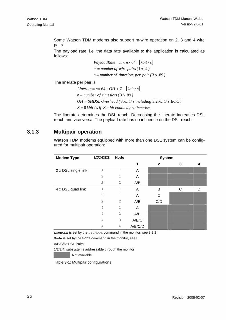
3.1.3 Multipair operation Watson TDM modems equipped with more than one DSL system can be config-ured for multipair operation: Modem Type LTUMODE Mode System 1 2 3 4 2 x DSL single link 1 1 A 2 1 A 2 2 A/B
4 x DSL quad link 1 1 A B C D 2 1 A C 2 2 A/B C/D 4 1 A 4 2 A/B 4 3 A/B/C 4 4 A/B/C/D LTUMODE is set by the LTUMODE command in the monitor, see 8.2.2
Mode is set by the MODE command in the monitor, see 0
A/B/C/D: DSL Pairs 1/2/3/4: subsystems addressable through the monitor
Not available
Table 3-1: Multipair configurations
Watson-TDM-Manual-W.doc
Version 2.0-01
Watson TDM Operating Manual
Revision: 2008-02-07 3-3
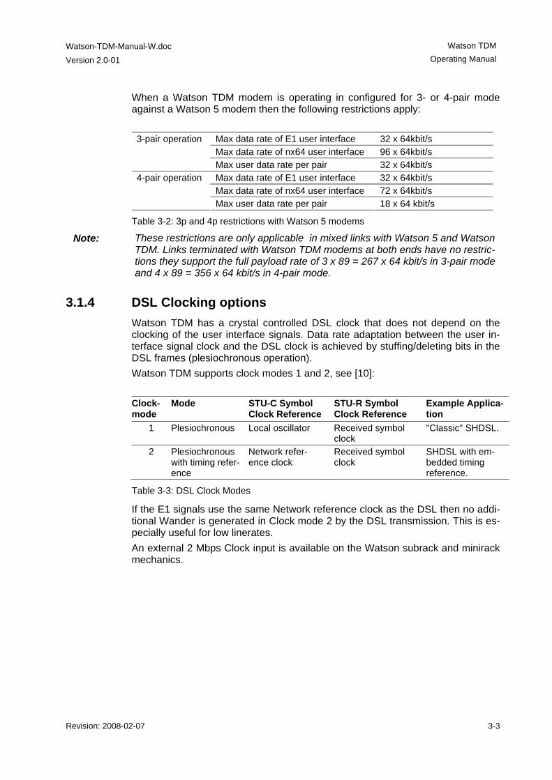
When a Watson TDM modem is operating in configured for 3- or 4-pair mode against a Watson 5 modem then the following restrictions apply:
Max data rate of E1 user interface 32 x 64kbit/s Max data rate of nx64 user interface 96 x 64kbit/s
3-pair operation
Max user data rate per pair 32 x 64kbit/s Max data rate of E1 user interface 32 x 64kbit/s Max data rate of nx64 user interface 72 x 64kbit/s
4-pair operation
Max user data rate per pair 18 x 64 kbit/s
Table 3-2: 3p and 4p restrictions with Watson 5 modems
Note: These restrictions are only applicable in mixed links with Watson 5 and Watson TDM. Links terminated with Watson TDM modems at both ends have no restric-tions they support the full payload rate of 3 x 89 = 267 x 64 kbit/s in 3-pair mode and 4 x 89 = 356 x 64 kbit/s in 4-pair mode.
3.1.4 DSL Clocking options Watson TDM has a crystal controlled DSL clock that does not depend on the clocking of the user interface signals. Data rate adaptation between the user in-terface signal clock and the DSL clock is achieved by stuffing/deleting bits in the DSL frames (plesiochronous operation). Watson TDM supports clock modes 1 and 2, see [10]: Clock-mode
Mode STU-C Symbol Clock Reference
STU-R Symbol Clock Reference
Example Applica-tion
1 Plesiochronous Local oscillator Received symbol clock
"Classic" SHDSL.
2 Plesiochronous with timing refer-ence
Network refer-ence clock
Received symbol clock
SHDSL with em-bedded timing reference.
Table 3-3: DSL Clock Modes
If the E1 signals use the same Network reference clock as the DSL then no addi-tional Wander is generated in Clock mode 2 by the DSL transmission. This is es-pecially useful for low linerates. An external 2 Mbps Clock input is available on the Watson subrack and minirack mechanics.

Watson TDM
Operating Manual
Watson-TDM-Manual-W.doc Version 2.0-01
3-4 Revision: 2008-02-07
3.1.5 Power Backoff In order to reduce interference on other transmission systems operating on adja-cent pairs bundled in the same cable, the DSL transmit power can be decreased by activating the power back-off mode. With enabled power back-off the transmit power will be reduced adaptively in function of the estimated power loss i. e. the estimated cable attenuation:
Estimated Power Loss(*) Power Backoff < 1 dB 6 dB < 2 dB 5 dB < 3 dB 4 dB < 4 dB 3 dB < 5 dB 2 dB < 6 dB 1 dB ≥ 6 dB no backoff
(*) Calculated as Tx Power – Estimated Rx Power
Table 3-4: Power Backoff
Activating the power backoff setting on one end of a DSL link causes the other end of the link to reduce its transmit power. Power backoff can be enabled individually for both ends of the link. Since the STU-R always follows the configuration of the STU-C enabling power backoff on the STU-C causes a symmetrical situation with STU-C and STU-R both using power backoff:
STU-C STU-R
Monitor settingBACKOFF ONin STU-C
Transmit power STU-R --> STU-C reduced
Transmit power STU-C --> STU-R reduced
Monitor settingBACKOFF ONin STU-R
Figure 3-1: Power backoff
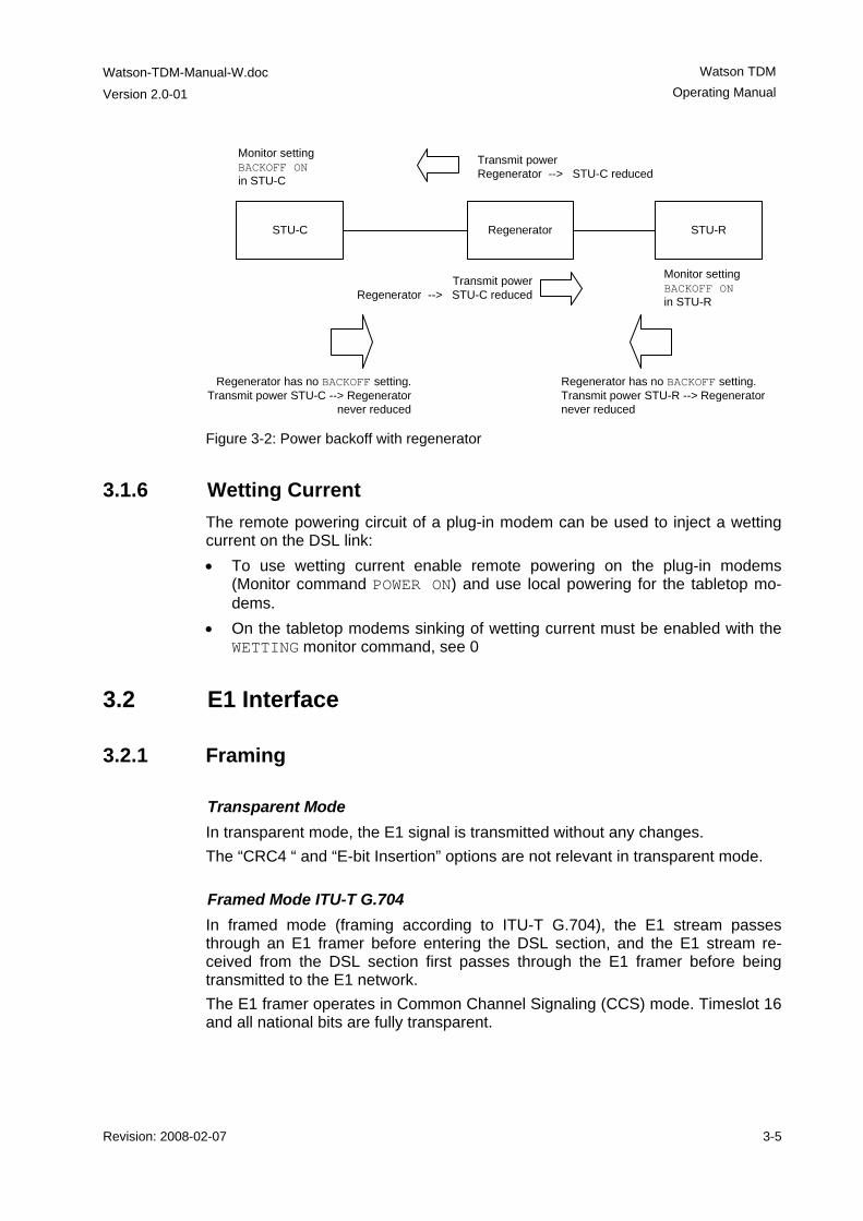
There is no power backoff setting in regenerators. A regenerator is however ca-pable of reducing its transmit power if the other end of the link has power backoff enabled:
Watson-TDM-Manual-W.doc
Version 2.0-01
Watson TDM Operating Manual
Revision: 2008-02-07 3-5
Monitor settingBACKOFF ONin STU-C
STU-C STU-R
Regenerator has no BACKOFF setting. Transmit power STU-C --> Regenerator
never reduced
Regenerator
Transmit power Regenerator --> STU-C reduced
Transmit power Regenerator --> STU-C reduced
Regenerator has no BACKOFF setting. Transmit power STU-R --> Regenerator never reduced
Monitor settingBACKOFF ONin STU-R
Figure 3-2: Power backoff with regenerator
3.1.6 Wetting Current The remote powering circuit of a plug-in modem can be used to inject a wetting current on the DSL link: • To use wetting current enable remote powering on the plug-in modems
(Monitor command POWER ON) and use local powering for the tabletop mo-dems.
• On the tabletop modems sinking of wetting current must be enabled with the WETTING monitor command, see 0
3.2 E1 Interface
3.2.1 Framing
Transparent Mode In transparent mode, the E1 signal is transmitted without any changes. The “CRC4 “ and “E-bit Insertion” options are not relevant in transparent mode.
Framed Mode ITU-T G.704 In framed mode (framing according to ITU-T G.704), the E1 stream passes through an E1 framer before entering the DSL section, and the E1 stream re-ceived from the DSL section first passes through the E1 framer before being transmitted to the E1 network. The E1 framer operates in Common Channel Signaling (CCS) mode. Timeslot 16 and all national bits are fully transparent.
Watson TDM
Operating Manual
Watson-TDM-Manual-W.doc Version 2.0-01
3-6 Revision: 2008-02-07
CRC-4 and E-bit insertion are supported in framed mode:
CRC4 • If enabled, the E1 framer synchronizes on CRC4 multiframes and CRC4 er-
rors are reported. In the outgoing E1 signal the framer generates the CRC4 multiframe alignment and checksum words. The A-Bit and the Sa-Bits pass transparently.
• If disabled, the international bits are set to ‘1’ in the outgoing E1 signal. All na-tional bits are fully transparent. On the receive side, the E1 framer synchro-nizes on basic frames only and no CRC4 errors are reported.
E-bit Insertion • If automatic E-Bit generation is enabled, detected CRC4 errors will cause the
assertion of the E-bits. • If disabled, all E-Bits are set to ‘1’.
3.2.2 AIS Detection If AIS detection is enabled, receiving AIS from the E1 side causes the following actions: • The Non-Urgent alarm is activated (AIS-S). • AIS is transmitted to the remote station by sending AIS-R over the DSL With AIS detection disabled AIS from the E1 interface is ignored.
3.2.3 AIS Generation If this option is enabled, AIS is sent over the local E1 interface if • the DSL link to the remote station is not established (loss of signal or loss of
frame alignment on DSL side) or • the remote station is sending AIS-R. If AIS generation is disabled, no signal is transmitted on the E1 side. The E1 in-terface will be switched off if either of these two conditions arises. AIS Generation can also be set to transparent: in this mode AIS is sent on the lo-cal E1 interface if AIS is signaled from the remote interface (reception of AIS-R). The local E1 interface is switched off if the DSL link looses synchronization.
Watson-TDM-Manual-W.doc
Version 2.0-01
Watson TDM Operating Manual
Revision: 2008-02-07 3-7
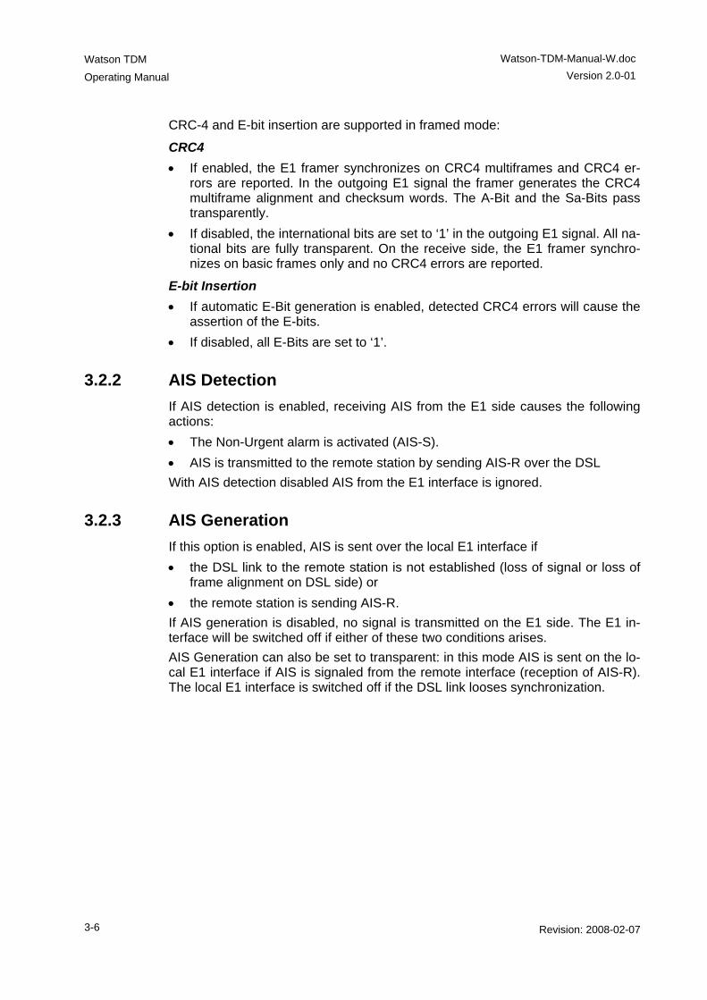
3.2.4 E1 Clock Modes
Clock architecture The following block diagram shows the clock architecture of the modems. The external clock option is only available on plug-in modems.
E1Tx
External Clock
DSLTx
E1 Rx
DSLRxRecovered 2048 kHz
Clock
2 Mbit/s Tx Clock
INP 2048 kHz
E1 Side
DSL Side
Internal Clock(Multipoint)
Stuff/Delete
2'048 KHz Clock
Recovery
Figure 3-3: Clock architecture
Note: Signals sent towards the DSL link are denoted as Tx and signals coming from the DSL link are denoted as Rx. As long as the DSL link is not established, the internal clock signal is used as clock source. The clock sources are automatically switched by the microcontroller, depending on the current signal and clock status, which is updated every 100 ms. The transmit clocks of the two E1 data directions are independent of each other. Both plesiochronous and synchronous operation modes are possible. Synchro-nous operation occurs when the E1 equipment at one end of the DSL link uses the receive clock as transmit clock, as shown below.
Tx
Rx
Rx2048 kHz Clock
E1 Equipment
DSL
E1 Equipment
TxModem Modem
Figure 3-4: Synchronous Operation (=”Loop Timing”)
Warning: Do not configure the E1 interfaces at both ends to use the receive clock as transmit clock except if one DSL modem is a plug-in card using the “External Clock” or "Internal clock" option. Otherwise there will be no defined clock.
Watson TDM
Operating Manual
Watson-TDM-Manual-W.doc Version 2.0-01
3-8 Revision: 2008-02-07
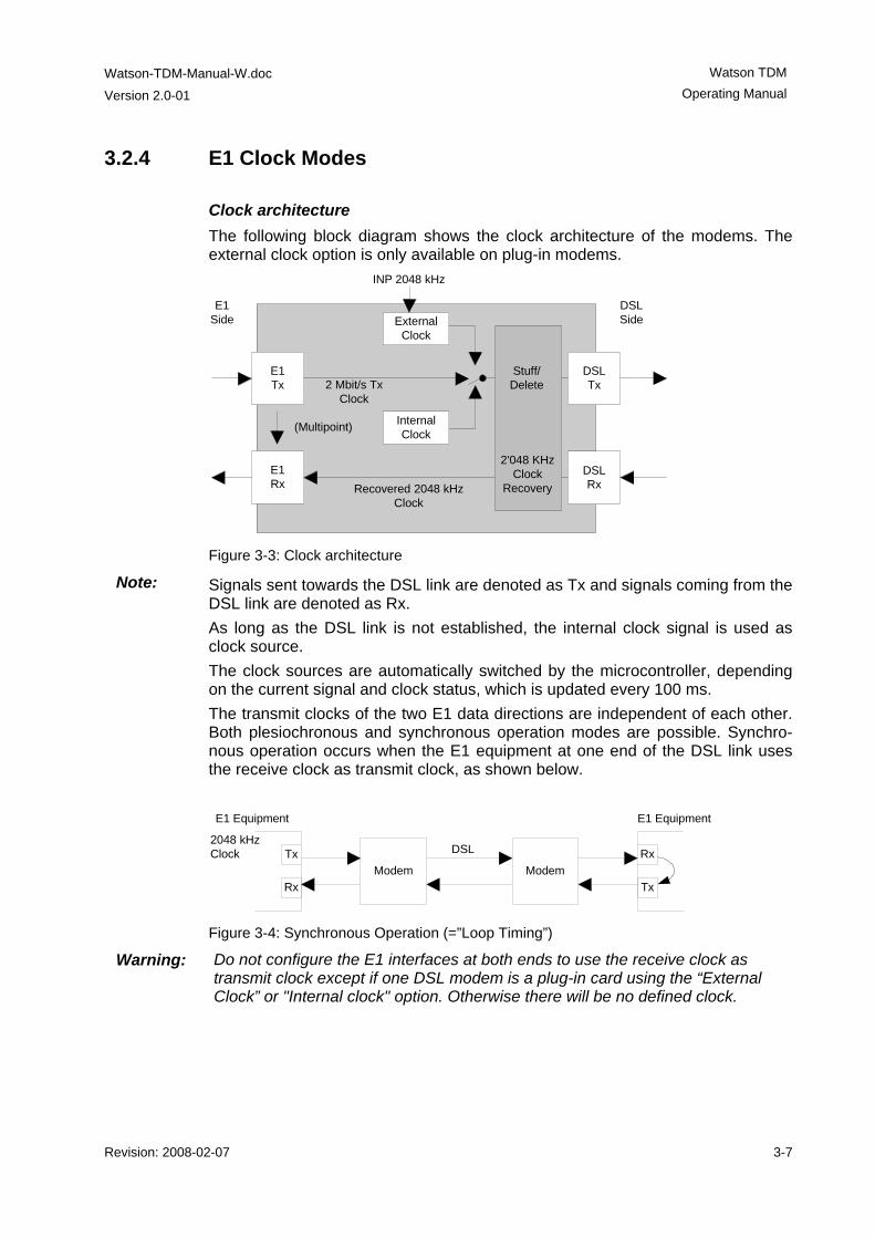
External Clock Mode
TabletopModem
Plug-inModem
DSLTx
Rx
Rx
Tx
E1E1
External Clock 2048 kHz
Figure 3-5: External Clock Mode
In external clock mode, the 2048kHz input clock is fed directly in the plug-in from the clock input of the minirack mechanics or via the ACU clock input. The exter-nal clock is used as the E1 reference clock. If no external clock is present at the 2048kHz clock input, the E1 transmit clock is used as the clock source. If no signal is received at the E1 Port, then the internal clock is used as the clock source. If the external clock option is disabled, the primary E1 clock source is the 2Mbit/s transmit clock. If no signal is received at the E1 Port, then the internal clock is used as the clock source. The external clock is never used to drive the E1 Rx direction.
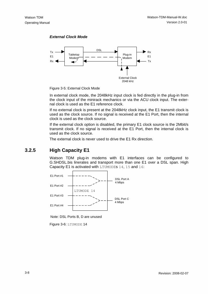
3.2.5 High Capacity E1 Watson TDM plug-in modems with E1 interfaces can be configured to G.SHDSL.bis linerates and transport more than one E1 over a DSL span. High Capacity E1 is activated with LTUMODEs 14, 15 and 16:
LTUMODE 14
E1 Port #1
E1 Port #2
E1 Port #3
E1 Port #4
DSL Port A4 Mbps
DSL Port C4 Mbps
Note: DSL Ports B, D are unused Figure 3-6: LTUMODE 14
Watson-TDM-Manual-W.doc
Version 2.0-01
Watson TDM Operating Manual
Revision: 2008-02-07 3-9
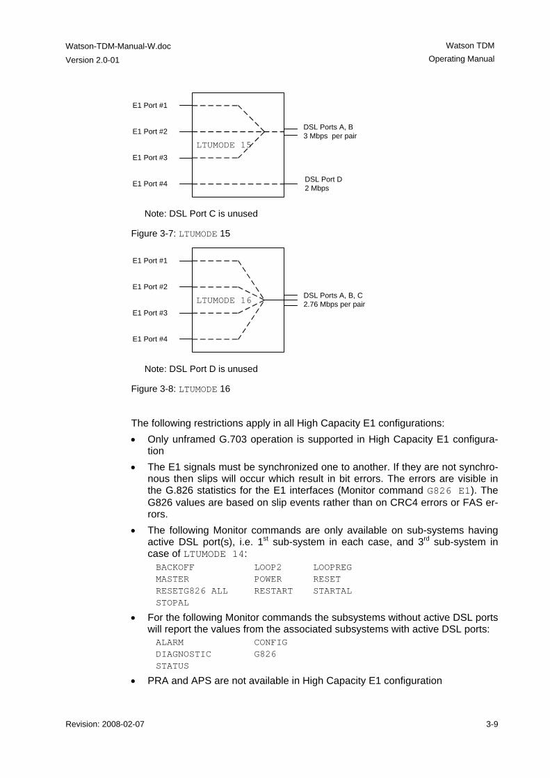
LTUMODE 15
E1 Port #1
E1 Port #2
E1 Port #3
E1 Port #4 DSL Port D2 Mbps
Note: DSL Port C is unused
DSL Ports A, B3 Mbps per pair
Figure 3-7: LTUMODE 15
LTUMODE 16
E1 Port #1
E1 Port #2
E1 Port #3
E1 Port #4
Note: DSL Port D is unused
DSL Ports A, B, C2.76 Mbps per pair
Figure 3-8: LTUMODE 16
The following restrictions apply in all High Capacity E1 configurations: • Only unframed G.703 operation is supported in High Capacity E1 configura-
tion • The E1 signals must be synchronized one to another. If they are not synchro-
nous then slips will occur which result in bit errors. The errors are visible in the G.826 statistics for the E1 interfaces (Monitor command G826 E1). The G826 values are based on slip events rather than on CRC4 errors or FAS er-rors.
• The following Monitor commands are only available on sub-systems having active DSL port(s), i.e. 1st sub-system in each case, and 3rd sub-system in case of LTUMODE 14: BACKOFF LOOP2 LOOPREG MASTER POWER RESET RESETG826 ALL RESTART STARTAL STOPAL
• For the following Monitor commands the subsystems without active DSL ports will report the values from the associated subsystems with active DSL ports: ALARM CONFIG DIAGNOSTIC G826 STATUS
• PRA and APS are not available in High Capacity E1 configuration
Watson TDM
Operating Manual
Watson-TDM-Manual-W.doc Version 2.0-01
3-10 Revision: 2008-02-07
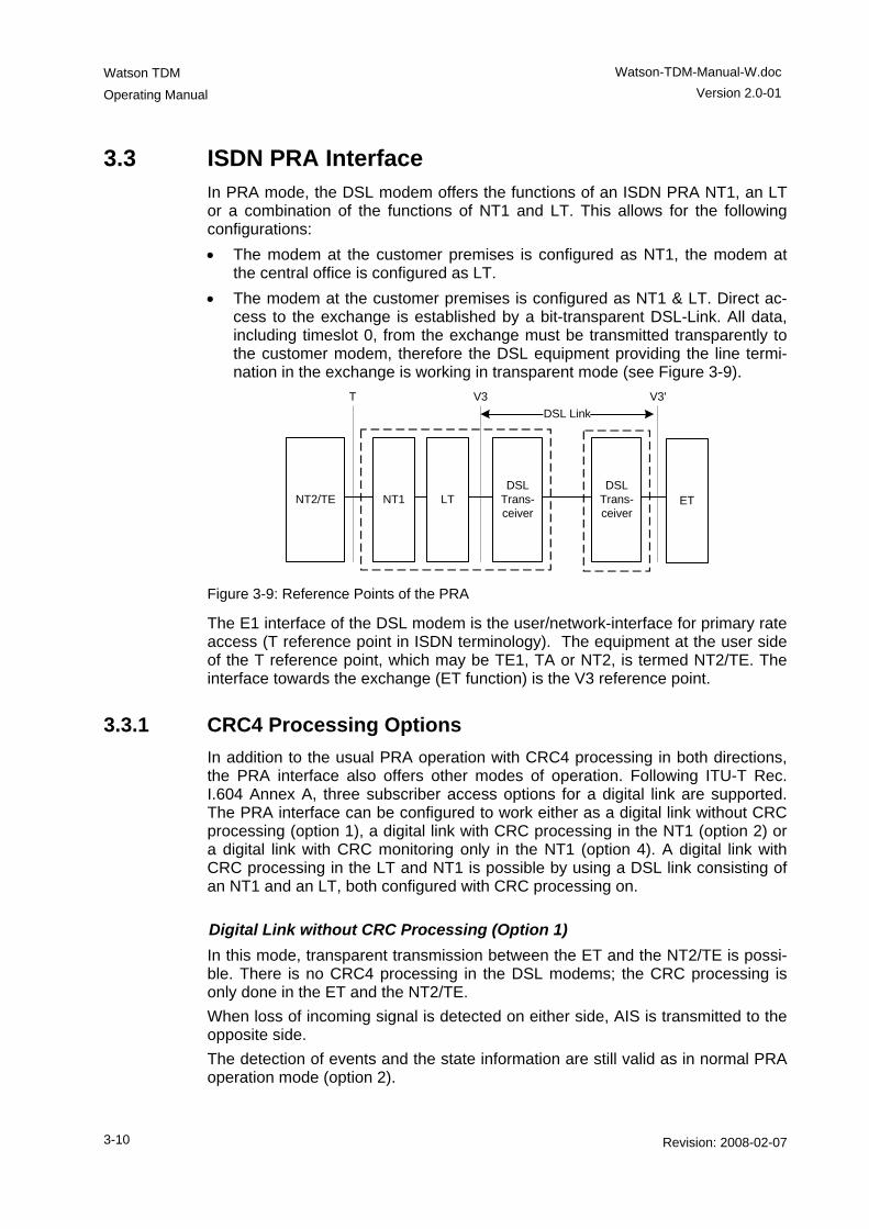
3.3 ISDN PRA Interface In PRA mode, the DSL modem offers the functions of an ISDN PRA NT1, an LT or a combination of the functions of NT1 and LT. This allows for the following configurations: • The modem at the customer premises is configured as NT1, the modem at
the central office is configured as LT. • The modem at the customer premises is configured as NT1 & LT. Direct ac-
cess to the exchange is established by a bit-transparent DSL-Link. All data, including timeslot 0, from the exchange must be transmitted transparently to the customer modem, therefore the DSL equipment providing the line termi-nation in the exchange is working in transparent mode (see Figure 3-9).
NT2/TE NT1 LTDSL
Trans-ceiver
DSL Trans-ceiver
ET
T V3 V3'DSL Link
Figure 3-9: Reference Points of the PRA
The E1 interface of the DSL modem is the user/network-interface for primary rate access (T reference point in ISDN terminology). The equipment at the user side of the T reference point, which may be TE1, TA or NT2, is termed NT2/TE. The interface towards the exchange (ET function) is the V3 reference point.
3.3.1 CRC4 Processing Options In addition to the usual PRA operation with CRC4 processing in both directions, the PRA interface also offers other modes of operation. Following ITU-T Rec. I.604 Annex A, three subscriber access options for a digital link are supported. The PRA interface can be configured to work either as a digital link without CRC processing (option 1), a digital link with CRC processing in the NT1 (option 2) or a digital link with CRC monitoring only in the NT1 (option 4). A digital link with CRC processing in the LT and NT1 is possible by using a DSL link consisting of an NT1 and an LT, both configured with CRC processing on.
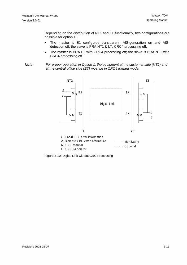
Digital Link without CRC Processing (Option 1) In this mode, transparent transmission between the ET and the NT2/TE is possi-ble. There is no CRC4 processing in the DSL modems; the CRC processing is only done in the ET and the NT2/TE. When loss of incoming signal is detected on either side, AIS is transmitted to the opposite side. The detection of events and the state information are still valid as in normal PRA operation mode (option 2).
Watson-TDM-Manual-W.doc
Version 2.0-01
Watson TDM Operating Manual
Revision: 2008-02-07 3-11
Depending on the distribution of NT1 and LT functionality, two configurations are possible for option 1: • The master is E1 configured transparent, AIS-generation on and AIS-
detection off; the slave is PRA NT1 & LT, CRC4 processing off. • The master is PRA LT with CRC4 processing off; the slave is PRA NT1 with
CRC4 processing off.
Note: For proper operation in Option 1, the equipment at the customer side (NT2) and at the central office side (ET) must be in CRC4 framed mode.
LRMG
Local CRC error informationRemote CRC error informationCRC MonitorCRC Generator
OptionalMandatory
Digital Link
T V3'
M
G
G
M
NT2 ET
R
L
L
R
RX
TX
TX
RX
Figure 3-10: Digital Link without CRC Processing
Watson TDM
Operating Manual
Watson-TDM-Manual-W.doc Version 2.0-01
3-12 Revision: 2008-02-07
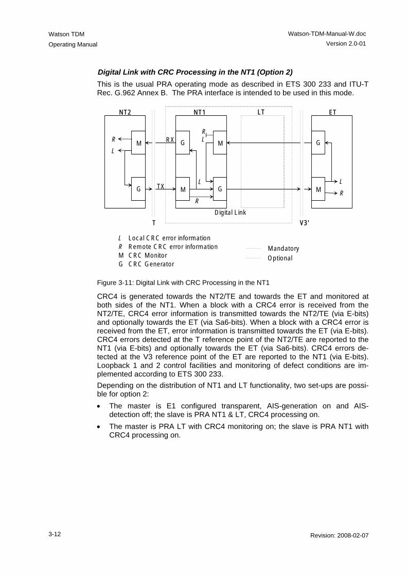
Digital Link with CRC Processing in the NT1 (Option 2) This is the usual PRA operating mode as described in ETS 300 233 and ITU-T Rec. G.962 Annex B. The PRA interface is intended to be used in this mode.
LRMG
Local CRC error informationRemote CRC error informationCRC MonitorCRC Generator
OptionalMandatory
Digital Link
NT2
G
M
ET
L
R
R
L
T V3'
NT1 LT
L R
L
R
G
M G
M
M
G
RX
TX
Figure 3-11: Digital Link with CRC Processing in the NT1
CRC4 is generated towards the NT2/TE and towards the ET and monitored at both sides of the NT1. When a block with a CRC4 error is received from the NT2/TE, CRC4 error information is transmitted towards the NT2/TE (via E-bits) and optionally towards the ET (via Sa6-bits). When a block with a CRC4 error is received from the ET, error information is transmitted towards the ET (via E-bits). CRC4 errors detected at the T reference point of the NT2/TE are reported to the NT1 (via E-bits) and optionally towards the ET (via Sa6-bits). CRC4 errors de-tected at the V3 reference point of the ET are reported to the NT1 (via E-bits). Loopback 1 and 2 control facilities and monitoring of defect conditions are im-plemented according to ETS 300 233. Depending on the distribution of NT1 and LT functionality, two set-ups are possi-ble for option 2: • The master is E1 configured transparent, AIS-generation on and AIS-
detection off; the slave is PRA NT1 & LT, CRC4 processing on. • The master is PRA LT with CRC4 monitoring on; the slave is PRA NT1 with
CRC4 processing on.
Watson-TDM-Manual-W.doc
Version 2.0-01
Watson TDM Operating Manual
Revision: 2008-02-07 3-13
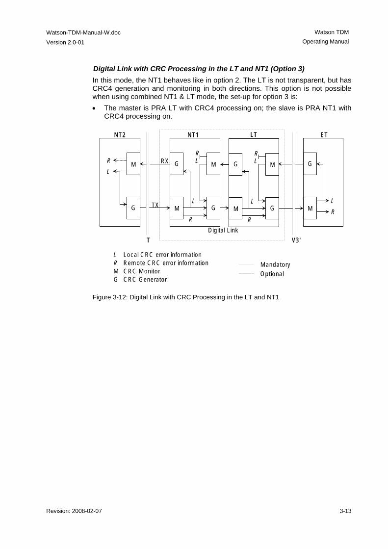
Digital Link with CRC Processing in the LT and NT1 (Option 3) In this mode, the NT1 behaves like in option 2. The LT is not transparent, but has CRC4 generation and monitoring in both directions. This option is not possible when using combined NT1 & LT mode, the set-up for option 3 is: • The master is PRA LT with CRC4 processing on; the slave is PRA NT1 with
CRC4 processing on.
LRMG
Local CRC error informationRemote CRC error informationCRC MonitorCRC Generator
OptionalMandatory
Digital Link
NT2
G
M
ET
L
R
R
L
T V3'
NT1 LT
L R
L
R
G
M G
M
M
G
RX
TX
L R
L
R
G
M G
M
Figure 3-12: Digital Link with CRC Processing in the LT and NT1
Watson TDM
Operating Manual
Watson-TDM-Manual-W.doc Version 2.0-01
3-14 Revision: 2008-02-07
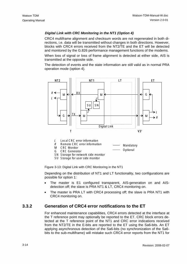
Digital Link with CRC Monitoring in the NT1 (Option 4) CRC4 multiframe alignment and checksum words are not regenerated in both di-rections, i.e. data will be transmitted without changes in both directions. However, blocks with CRC4 errors received from the NT2/TE and the ET will be detected and monitored by the G.826 performance management functions of the modems. When loss of signal or loss of frame alignment is detected at either side, AIS is transmitted at the opposite side. The detection of events and the state information are still valid as in normal PRA operation mode (option 4).
LRMG
Local CRC error informationRemote CRC error informationCRC MonitorCRC Generator Optional
Mandatory
SNSU
Storage for network side monitorStorage for user side monitor
M
Digital Link
NT2
G
M
ET
L
R
R
L
T V3'
NT1 LT
M
M
G
SNSU
RX
TX
Figure 3-13: Digital Link with CRC Monitoring in the NT1
Depending on the distribution of NT1 and LT functionality, two configurations are possible for option 1: • The master is E1 configured transparent, AIS-generation on and AIS-
detection off; the slave is PRA NT1 & LT, CRC4 monitoring on. • The master is PRA LT with CRC4 processing off; the slave is PRA NT1 with
CRC4 monitoring on.
3.3.2 Generation of CRC4 error notifications to the ET For enhanced maintenance capabilities, CRC4 errors detected at the interface at the T reference point may optionally be reported to the ET. CRC block errors de-tected at the T reference point of the NT1 and CRC error indications received from the NT2/TE in the E-bits are reported to the ET using the Sa6-bits. An ET applying asynchronous detection of the Sa6-bits (no synchronization of the Sa6-bits to the sub-multiframe) will mistake such CRC4 error reports from the NT1 for
Watson-TDM-Manual-W.doc
Version 2.0-01
Watson TDM Operating Manual
Revision: 2008-02-07 3-15
other errors, e.g. loss of power at NT1 or FC4. To avoid this it is possible to dis-able Sa6-bit indication. If the CRC4 error notification in Sa6 is enabled, Sa6=0001 indicates an E-bit re-ceived from the NT2/TE, Sa6=0010 indicates a CRC4 error detected at the T ref-erence point of the NT1, and Sa6=0011 indicates the simultaneous occurrence of both errors. If disabled, Sa6 is always 0000 in normal operation state. As sending of Sa-bits requires regeneration of the CRC4 frames in the NT1, this option is only activated when option 2 (Digital link with CRC processing in the NT1) is selected.
3.4 nx64 kbit/s Interface
3.4.1 Features • The nx64 kbit/s interface is software-configurable between V.35, V.36 and
X.21. • The bitrate can be selected in steps of 64kbit/s from 64kbit/s (n=1) up to
9'984 Kbps (n = 156) • Independent receive and transmit clocks for V.35 and V.36. • Transmit clock is configurable either co-directional (clock defined by user
equipment connected to nx64 Port) or contra-directional (clock generated from internal reference or from receiving clock).
• Detection for loss of clock and clock rate mismatch in co-directional clock mode.
• Standard SubD25 connector (ISO 2110 for V.35, RS-530 for V.36, proprietary for X.21) for DCE operation, other connectors (ISO 2593 for V.35, ISO 4902 for V.36, ISO 4903 for X.21) both for operation as DCE or DTE are available by means of system cables.
• Loop 1 and Loop 2 supported, for V.35 and V.36. Loop control is also possi-ble by circuits 140 (RL) and 141 (LL), according to V.54.
• Support for byte timing (circuit B) in X.21 mode. • Activity indication of nx64 kbit/s interface on front LED of tabletop if operated
as DSL slave • Multiservice operation: it is possible to use nx64 kbit/s and an E1 user inter-
faces simultaneously, sharing share the DSL bitrate between them.
Watson TDM
Operating Manual
Watson-TDM-Manual-W.doc Version 2.0-01
3-16 Revision: 2008-02-07
3.4.2 Handshake Operation When no loopback is established, the control circuits perform the following hand-shake protocol: • 105 (RTS Request to send, X.21: C): Input from DTE. For X.21, C = OFF will
cause a DTR alarm. • 106 (CTS Ready for sending, X.21: I):
if Handshake option enabled: is set ON when a DSL connection is estab-lished and 105 = ON is detected.
if Handshake option disabled: is set ON when a DSL connection is estab-lished
• 107 (DSR Data set ready): is set ON when a DSL connection is established • 108 (DTR Data terminal ready): input from DTE. For V.35 and V.36, 108 =
OFF will cause a DTR alarm. • 109 (RLSD Data channel received line signal detector): is set ON when a
DSL connection is established. • 140 (RL Loopback / Maintenance test): Input from DTE; will be set OFF in
normal mode. • 141 (LL Local loopback): input from DTE; will be set OFF in normal mode. • 142 (TM Test indicator): is set OFF in normal mode.
3.4.3 Supported V.54 Loops ITU-T recommendation V.54 defines four test loops. Loops 2 and 3 correspond to DSL loopbacks 2 and 1. The interchange circuits are set in the following way: • V.54 Loop 2
Loop in remote DCE, i.e. DSL loopback 2 in the remote modem. The output interchange circuits are set as follows:
Master: 107 = ON and 142 = ON
Slave: 104 (received data) = 1, 106 = OFF, 107 = OFF, 109 = OFF and 142 = ON.
• V.54 Loop 3 Local loop established in the DCE, i.e. DSL loopback 1 in the local modem. The output interchange circuits are set as follows: 107 = ON and 142 = ON
3.4.4 Automatic Loop Control through the DTE/DCE Interface Automatic control through the interface is achieved by using circuits 140 and 141: • 140 = ON and 141 = OFF ⇒ V.54 loop 2 (DSL loopback 2) • 140 = OFF and 141 = ON ⇒ V.54 loop 3 (DSL loopback 1) This automatic loop control can be switched on/off using the V54LOOPS monitor command.
Watson-TDM-Manual-W.doc
Version 2.0-01
Watson TDM Operating Manual
Revision: 2008-02-07 3-17
3.4.5 Clock Direction For V.35 and V.36 interface types, the clock direction can be configured by the user. If codirectional, Transmit Data 103 is sampled with Transmit Clock 113. If contradirectional, Transmit Data 103 is sampled with Transmit Clock 114. It is recommended to use codirectional transmit timing whenever possible, in particu-lar for bitrates > 32 x 64 kbit/s.
3.4.6 Clock Polarity In X.21 mode the sampling instant for the incoming data stream on circuit T of the user interface (UIF) can be switched to the rising or falling slope of the contradi-rectional clock circuit S. Data transitions of the received data on UIF circuit R are not influenced by this setting. By default circuit T is sampled on rising edge of clock S. The data transitions on T and R occur at the OFF to ON transition of S (according X.24 standard). The ON to OFF transition of circuit S nominally indicates the center of each signal element, in this case on circuit R. When Clock Polarity is set to "inverted", circuit T is sampled with the falling slope of S. The incoming data at X.21 circuit T will be sampled at the OFF to ON transi-tion of S.
3.4.7 Byte Timing In the X.21 mode, the byte timing circuit B according to X.24 can be activated (Monitor command BYTETIMING) As the circuits B (byte timing) and X (co-directional transmit clock) share the same pins on the 15-pin ISO 4903 connec-tor, special cables have to be used in this case.
3.4.8 Multiservice / nx64 Clock Modes For V.35 and V.36, the receive and transmit clocks are independent. The receive clock is always the recovered remote clock. The clock mode configuration only applies to the transmit clock.
Note: The modem is a data communications equipment (DCE). Therefore the transmit clock is directed towards the modem, the receive clock is directed towards the data terminal equipment (DTE).
For X.21, there is only one clock (circuit S) to receive and transmit. The clock mode determines the source of that single clock; however, in the co-directional nx64 Port clock mode, X is used as a co-directional transmit clock and S is used only as receive clock. The following clock modes are supported: • nx64 Port: The transmit clock is the co-directional clock coming from the
equipment connected to the nx64 port (circuit 113, X). • E1 Port: The transmit clock is generated based on the transmit clock used at
the E1 port. It is available at the contra-directional transmit clock output (cir-
Watson TDM
Operating Manual
Watson-TDM-Manual-W.doc Version 2.0-01
3-18 Revision: 2008-02-07
cuit 114). This clock mode should be used for multiservice operation (simul-taneous use of E1 and nx64 kbit/s).
• Internal: The transmit clock is generated from the internal reference clock (contra-directional, circuit 114).
• Remote: The transmit clock is the recovered remote clock, i.e. the same clock as the receive clock (115) at the V.35 and V.36 interface (contra-directional, circuit 114).
The clock mode to be used depends on the network configuration. First thing to check is whether the equipment connected to the nx64 port uses a transmit clock output or input. In the first case, the co-directional nx64 port mode can be used. In the latter case, one of the contra-directional clock modes should be used. The internal clock mode should be suitable in most cases, the remote clock can be used if the receive and transmit clocks have to be equal. The contra-directional X.21 clock modes use only one clock signal. Therefore the following configurations are possible: nx64 port - nx64 port, nx64 port - remote, internal - remote. It is recommended to have at least one clock reference. Configurations with re-mote clocks on both ends must be avoided. Remote clocking will also lead to problems if the remote modem has an E1 inter-face and the E1 equipment connected to the remote E1 port uses loop timing (i.e. it uses the received clock as transmit clock).
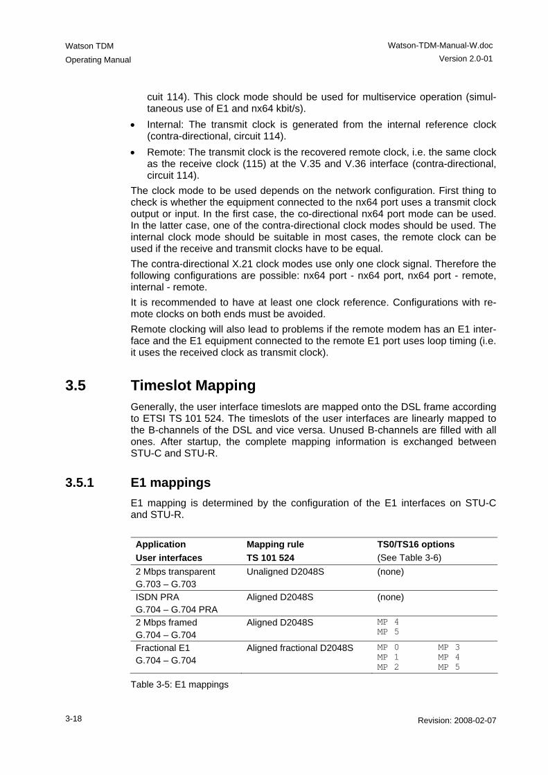
3.5 Timeslot Mapping Generally, the user interface timeslots are mapped onto the DSL frame according to ETSI TS 101 524. The timeslots of the user interfaces are linearly mapped to the B-channels of the DSL and vice versa. Unused B-channels are filled with all ones. After startup, the complete mapping information is exchanged between STU-C and STU-R.
3.5.1 E1 mappings E1 mapping is determined by the configuration of the E1 interfaces on STU-C and STU-R. Application User interfaces
Mapping rule TS 101 524
TS0/TS16 options (See Table 3-6)
2 Mbps transparent G.703 – G.703
Unaligned D2048S (none)
ISDN PRA G.704 – G.704 PRA
Aligned D2048S (none)
2 Mbps framed G.704 – G.704
Aligned D2048S MP 4 MP 5
Fractional E1 G.704 – G.704
Aligned fractional D2048S MP 0 MP 3 MP 1 MP 4 MP 2 MP 5
Table 3-5: E1 mappings
Watson-TDM-Manual-W.doc
Version 2.0-01
Watson TDM Operating Manual
Revision: 2008-02-07 3-19
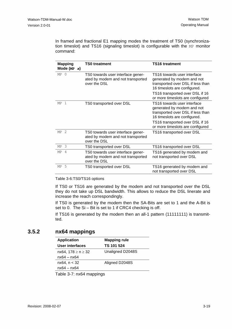
In framed and fractional E1 mapping modes the treatment of TS0 (synchroniza-tion timeslot) and TS16 (signaling timeslot) is configurable with the MP monitor command: Mapping Mode (MP x)
TS0 treatment TS16 treatment
MP 0 TS0 towards user interface gener-ated by modem and not transported over the DSL
TS16 towards user interface generated by modem and not transported over DSL if less than 16 timeslots are configured. TS16 transported over DSL if 16 or more timeslots are configured
MP 1 TS0 transported over DSL TS16 towards user interface generated by modem and not transported over DSL if less than 16 timeslots are configured. TS16 transported over DSL if 16 or more timeslots are configured
MP 2 TS0 towards user interface gener-ated by modem and not transported over the DSL
TS16 transported over DSL
MP 3 TS0 transported over DSL TS16 transported over DSL MP 4 TS0 towards user interface gener-
ated by modem and not transported over the DSL
TS16 generated by modem and not transported over DSL
MP 5 TS0 transported over DSL TS16 generated by modem and not transported over DSL
Table 3-6:TS0/TS16 options
If TS0 or TS16 are generated by the modem and not transported over the DSL they do not take up DSL bandwidth. This allows to reduce the DSL linerate and increase the reach correspondingly. If TS0 is generated by the modem then the SA-Bits are set to 1 and the A-Bit is set to 0. The Si – Bit is set to 1 if CRC4 checking is off. If TS16 is generated by the modem then an all-1 pattern (11111111) is transmit-ted.
3.5.2 nx64 mappings Application User interfaces
Mapping rule TS 101 524
nx64, 178 ≥ n ≥ 32 nx64 – nx64
Unaligned D2048S
nx64, n < 32 nx64 – nx64
Aligned D2048S
Table 3-7: nx64 mappings
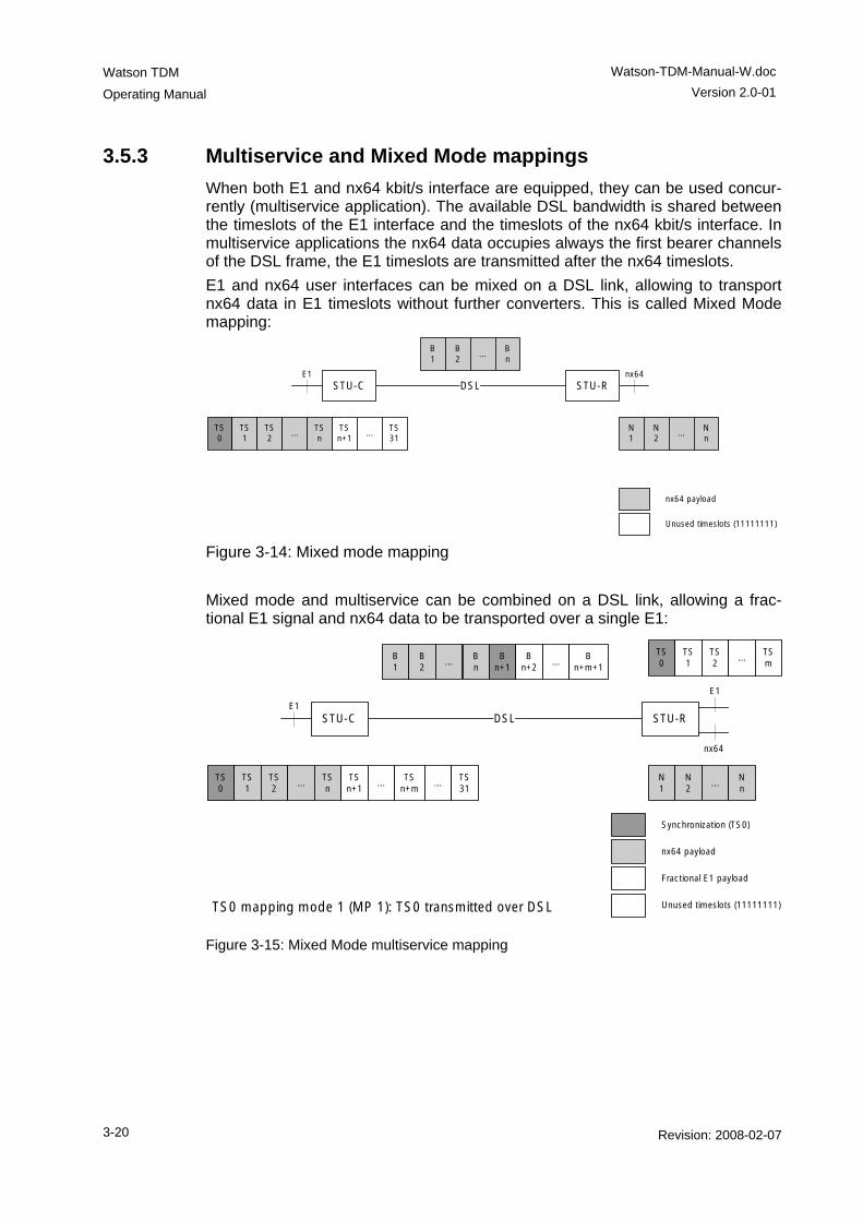
Watson TDM
Operating Manual
Watson-TDM-Manual-W.doc Version 2.0-01
3-20 Revision: 2008-02-07
3.5.3 Multiservice and Mixed Mode mappings When both E1 and nx64 kbit/s interface are equipped, they can be used concur-rently (multiservice application). The available DSL bandwidth is shared between the timeslots of the E1 interface and the timeslots of the nx64 kbit/s interface. In multiservice applications the nx64 data occupies always the first bearer channels of the DSL frame, the E1 timeslots are transmitted after the nx64 timeslots. E1 and nx64 user interfaces can be mixed on a DSL link, allowing to transport nx64 data in E1 timeslots without further converters. This is called Mixed Mode mapping:
DSLSTU-C STU-RE1 nx64
B1
B2
...Bn
TS0
TS1
TS2
...TSn
TSn+1
...TS31
N1
N2
...Nn
nx64 payload
Unused timeslots (11111111) Figure 3-14: Mixed mode mapping Mixed mode and multiservice can be combined on a DSL link, allowing a frac-tional E1 signal and nx64 data to be transported over a single E1:
DSLSTU-C STU-R
B1
B2
...
TS0
TS1
TS2
...TSn
TSn+1
...TS
n+mN1
N2
...Nn
Synchronization (TS0)
nx64 payload
Unused timeslots (11111111)
E1
E1
nx64
TS0
TS1
TS2
...TSm
Bn
Bn+1
Bn+2
...B
n+m+1
...TS31
Fractional E1 payload
TS0 mapping mode 1 (MP 1): TS0 transmitted over DSL
Figure 3-15: Mixed Mode multiservice mapping
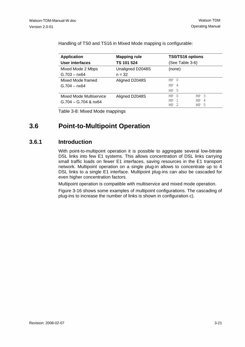
Watson-TDM-Manual-W.doc
Version 2.0-01
Watson TDM Operating Manual
Revision: 2008-02-07 3-21
Handling of TS0 and TS16 in Mixed Mode mapping is configurable: Application User interfaces
Mapping rule TS 101 524
TS0/TS16 options (See Table 3-6)
Mixed Mode 2 Mbps G.703 – nx64
Unaligned D2048S n = 32
(none)
Mixed Mode framed G.704 – nx64
Aligned D2048S MP 0 MP 4 MP 5
Mixed Mode Multiservice G.704 – G.704 & nx64
Aligned D2048S MP 0 MP 3 MP 1 MP 4 MP 2 MP 5
Table 3-8: Mixed Mode mappings
3.6 Point-to-Multipoint Operation
3.6.1 Introduction With point-to-multipoint operation it is possible to aggregate several low-bitrate DSL links into few E1 systems. This allows concentration of DSL links carrying small traffic loads on fewer E1 interfaces, saving resources in the E1 transport network. Multipoint operation on a single plug-in allows to concentrate up to 4 DSL links to a single E1 interface. Multipoint plug-ins can also be cascaded for even higher concentration factors. Multipoint operation is compatible with multiservice and mixed mode operation. Figure 3-16 shows some examples of multipoint configurations. The cascading of plug-ins to increase the number of links is shown in configuration c).
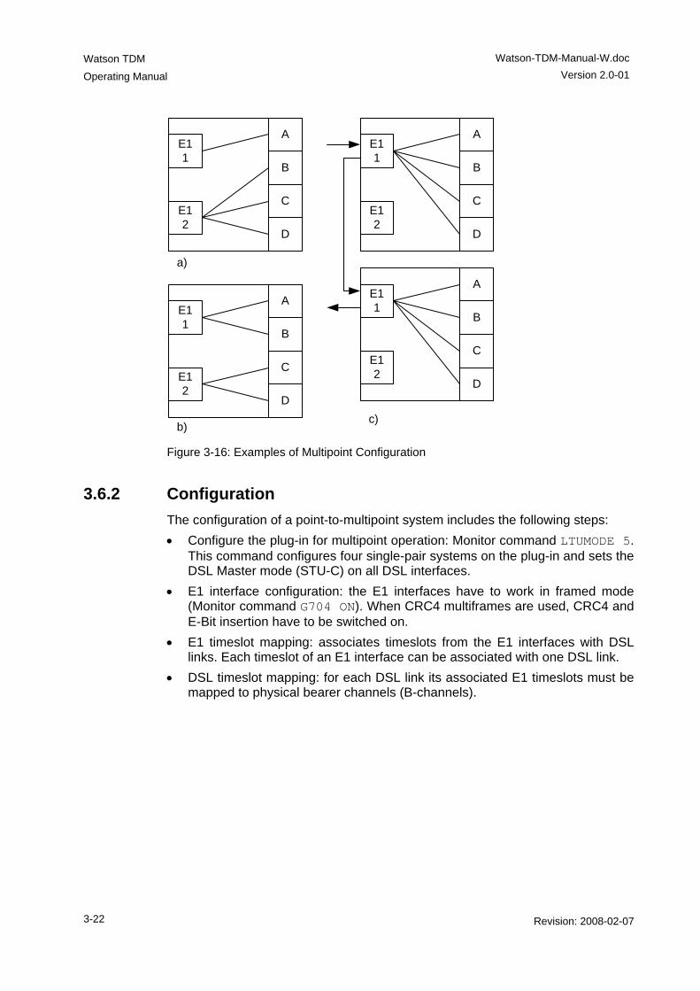
Watson TDM
Operating Manual
Watson-TDM-Manual-W.doc Version 2.0-01
3-22 Revision: 2008-02-07
D
A
B
C
E1 1
E1 2
D
A
B
C
E1 1
E1 2
D
A
B
C
E1 1
E1 2
D
A
B
C
E1 1
E1 2
a)
b)c)
Figure 3-16: Examples of Multipoint Configuration
3.6.2 Configuration The configuration of a point-to-multipoint system includes the following steps: • Configure the plug-in for multipoint operation: Monitor command LTUMODE 5.
This command configures four single-pair systems on the plug-in and sets the DSL Master mode (STU-C) on all DSL interfaces.
• E1 interface configuration: the E1 interfaces have to work in framed mode (Monitor command G704 ON). When CRC4 multiframes are used, CRC4 and E-Bit insertion have to be switched on.
• E1 timeslot mapping: associates timeslots from the E1 interfaces with DSL links. Each timeslot of an E1 interface can be associated with one DSL link.
• DSL timeslot mapping: for each DSL link its associated E1 timeslots must be mapped to physical bearer channels (B-channels).
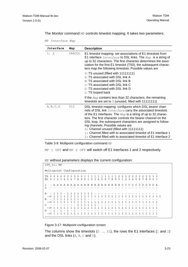
Watson-TDM-Manual-W.doc
Version 2.0-01
Watson TDM Operating Manual
Revision: 2008-02-07 3-23
The Monitor command MP controls timeslot mapping. It takes two parameters: MP Interface Map
Interface Map Description 1, 2 0ABCDL E1 timeslot mapping: set associations of E1 timeslots from
E1 interface Interface to DSL links. The Map is a string of up to 32 characters. The first character determines the asso-ciation for the first E1 timeslot (TS0), the subsequent charac-ters map the following timeslots. Possible values are 0: TS unused (filled with 11111111) A: TS associated with DSL link A B: TS associated with DSL link B C: TS associated with DSL link C D: TS associated with DSL link D L: TS looped back If the Map contains less than 32 characters, the remaining timeslots are set to 0 (unused, filled with 11111111)
A,B,C,D 012 DSL timeslot mapping: configures which DSL bearer chan-nels of DSL link Interface carry the associated timeslots of the E1 interfaces. The Map is a string of up to 32 charac-ters. The first character controls the bearer channel on the DSL loop, the subsequent characters are assigned to follow-ing channels. Possible values are 0: Channel unused (filled with 11111111) 1: Channel filled with to associated timeslot of E1 interface 12: Channel filled with to associated timeslot of E1 interface 2
Table 3-9: Multipoint configuration command MP
MP 1 OFF and MP 2 OFF will switch off E1 interfaces 1 and 2 respectively.
MP without parameters displays the current configuration: LTU_01> MP Multipoint Configuration ~~~~~~~~~~~~~~~~~~~~~~~~~~~~~~~~~~~~~~~~~~~~~~~~~~~~~~~~~~~~~~~~~~ TS 0 0 0 0 0 0 0 0 0 0 1 1 1 1 1 1 1 1 1 1 2 2 2 2 2 2 2 2 2 2 3 3 Nr 0 1 2 3 4 5 6 7 8 9 0 1 2 3 4 5 6 7 8 9 0 1 2 3 4 5 6 7 8 9 0 1 1 - A A A A A A A A A A B B B B B B B B B B C C C C C C D D D D A 2 - - - - - - - - - - - - - - - - - - - - - - - - - - - - - - - - A - 1 1 1 - 1 1 1 1 1 1 1 1 - - - - - - - - - - - - - - - - - - - ->0 1 1 1 1 1 1 1 1 1 1 1 1 1 1 1 1 1 1 1 1 1 1 1 1 1 1 1 1 1 1 1 1 B - 1 1 1 1 1 1 1 1 1 1 - - - - - - - - - - - - - - - - - - - - - ->0 1 1 1 1 1 1 1 1 1 1 1 1 1 1 1 1 1 1 1 1 1 1 1 1 1 1 1 1 1 1 1 C - - - - - - - - 1 1 1 1 1 1 - - - - - - - - - - - - - - - - - - ->0 1 1 1 1 1 1 1 1 1 1 1 1 1 1 1 1 1 1 1 1 1 1 1 1 1 1 1 1 1 1 1 D - 1 - 1 - 1 - 1 - - - - - - - - - - - - - - - - - - - - - - - - ->0 1 1 1 1 1 1 1 1 1 1 1 1 1 1 1 1 1 1 1 1 1 1 1 1 1 1 1 1 1 1 1 ~~~~~~~~~~~~~~~~~~~~~~~~~~~~~~~~~~~~~~~~~~~~~~~~~~~~~~~~~~~~~~~~~~
Figure 3-17: Multipoint configuration screen
The columns show the timeslots (0 … 31), the rows the E1 interfaces (1 and 2) and the DSL links (A, B, C and D).
Watson TDM
Operating Manual
Watson-TDM-Manual-W.doc Version 2.0-01
3-24 Revision: 2008-02-07
In the configuration shown in Figure 3-18 the following mapping rules are active: E1 interface 1 TS0 unused, i. e. TS0 towards the E1 interface is gen-
erated by the modem and not transported over the DSL
E1 interface 1 TS 1 - 3 transported over DSL link A, channels 1 – 3 E1 interface 1, TS 4 - 10 transported over DSL link A, channels 1 – 11 E1 interface 1 TS 11 - 20 transported over DSL link B, channels 1 – 10 E1 interface 1 TS 21 - 26 transported over DSL link C, channels 8 – 13 E1 interface 1 TS 27 transported over DSL link D, channel 1 E1 interface 1 TS 28 transported over DSL link D, channel 3 E1 interface 1 TS 29 transported over DSL link D, channel 5 E1 interface 1 TS 30 transported over DSL link D, channel 7 E1 interface 1 TS 27 transported over DSL link A, channel 12 The E1 interface 2 and all other DSL channels are unused. This is indicated by the hyphen character – The MP configuration screen also displays how the remote modem maps DSL channels to its local E1 or nx64 interface. This is indicated on the lines marked with -> (below A, B, C and D) with the following symbols: 1 DSL channel mapped to the corresponding E1 timeslot N DSL channel mapped to the nx64 user interface 0 channel not mapped to the E1 user interface Note that the multipoint configuration will not change any timeslot mapping on the remote modem. Proper configuration of both multipoint and remote mapping must be done to avoid any mapping conflicts or ambiguities. The symbol ! at the be-ginning of a -> line indicates a conflict on the time slot mapping between local and remote modem.
Notes: • The E1 timeslot mapping characters are shown in lowercase (a .. d) if a time-slot has been associated with a DSL link, but its channel on that link has not yet been defined. Timeslots which are associated with a channel on the DSL link are displayed in uppercase (A .. D) in the E1 timeslot mapping.
• If you select more timeslots in the DSL timeslot mapping than are currently mapped to the link by the E1 timeslot mapping, superfluous timeslots will not be enabled. Also timeslots which are outside of the range used by the line rate configured will not be enabled.
• TS0 is used for E1 framing (FAS/NFAS) and is normally generated at the re-mote modem. TS0 on the DSL links can only be used for transmission of TS0 from one E1 interface at the multipoint modem.
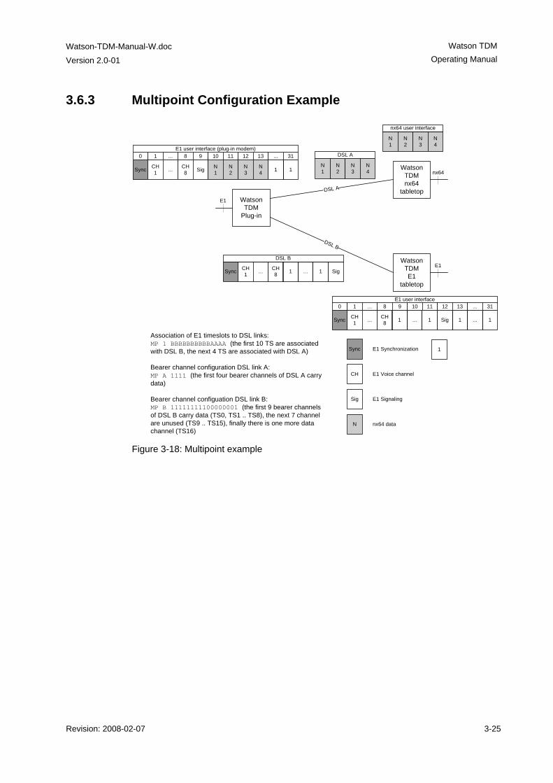
Watson-TDM-Manual-W.doc
Version 2.0-01
Watson TDM Operating Manual
Revision: 2008-02-07 3-25
3.6.3 Multipoint Configuration Example
Watson TDM
Plug-in
Watson TDMnx64
tabletop
Watson TDME1
tabletop
DSL A
DSL B
E1
E1
nx64
N1
N2
N3
N4
Sync CH1 ... CH
8 1 ... 1 Sig 1 ... 1
Sync CH1 ... CH
8 1 1Sig N1
N2
N3
N4
0 1 8 9 10 11 12 13 ... 31...
N1
N2
N3
N4
Sync CH1 ... CH
8 1 ... 1 Sig
DSL B
E1 user interface
nx64 user interface
DSL AE1 user interface (plug-in modem)
Association of E1 timeslots to DSL links:MP 1 BBBBBBBBBBAAAA (the first 10 TS are associated with DSL B, the next 4 TS are associated with DSL A)
Bearer channel configuration DSL link A:MP A 1111 (the first four bearer channels of DSL A carry data)
Bearer channel configuation DSL link B:MP B 11111111100000001 (the first 9 bearer channels of DSL B carry data (TS0, TS1 .. TS8), the next 7 channel are unused (TS9 .. TS15), finally there is one more data channel (TS16)
0 1 8 9 10 11 12 13 ... 31...
Sync
CH
Sig
N
E1 Synchronization
E1 Voice channel
E1 Signaling
nx64 data
1
Figure 3-18: Multipoint example
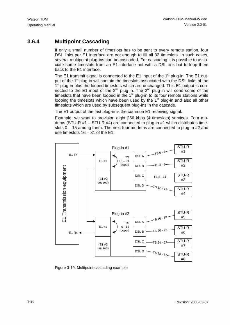
Watson TDM
Operating Manual
Watson-TDM-Manual-W.doc Version 2.0-01
3-26 Revision: 2008-02-07
3.6.4 Multipoint Cascading If only a small number of timeslots has to be sent to every remote station, four DSL links per E1 interface are not enough to fill all 32 timeslots. In such cases, several multipoint plug-ins can be cascaded. For cascading it is possible to asso-ciate some timeslots from an E1 interface not with a DSL link but to loop them back to the E1 interface. The E1 transmit signal is connected to the E1 input of the 1st plug-in. The E1 out-put of the 1st plug-in will contain the timeslots associated with the DSL links of the 1st plug-in plus the looped timeslots which are unchanged. This E1 output is con-nected to the E1 input of the 2nd plug-in. The 2nd plug-in will send some of the timeslots that have been looped in the 1st plug-in to its four remote stations while looping the timeslots which have been used by the 1st plug-in and also all other timeslots which are used by subsequent plug-ins in the cascade. The E1 output of the last plug-in is the common E1 receiving signal. Example: we want to provision eight 256 kbps (4 timeslots) services. Four mo-dems (STU-R #1 – STU-R #4) are connected to plug-in #1 which distributes time-slots 0 – 15 among them. The next four modems are connected to plug-in #2 and use timeslots 16 – 31 of the E1:
Plug-in #1
DSL A
DSL B
DSL C
DSL D
E1 #1
STU-R #1
TS 0 - 3
TS 4 - 7
TS 8 - 11
TS 12 - 15
TS 16 – 31 looped
(E1 #2 unused)
E1 Tx
Plug-in #2
DSL A
DSL B
DSL C
DSL D
E1 #1
TS 16 - 19
TS 20 - 23
TS 24 - 27
TS 28 - 31
TS 0 - 15
looped
(E1 #2 unused)
E1 Rx
E1 T
rans
mis
sion
equ
ipm
ent
STU-R #2
STU-R #3
STU-R #4
STU-R #5
STU-R #6
STU-R #7
STU-R #8
Figure 3-19: Multipoint cascading example
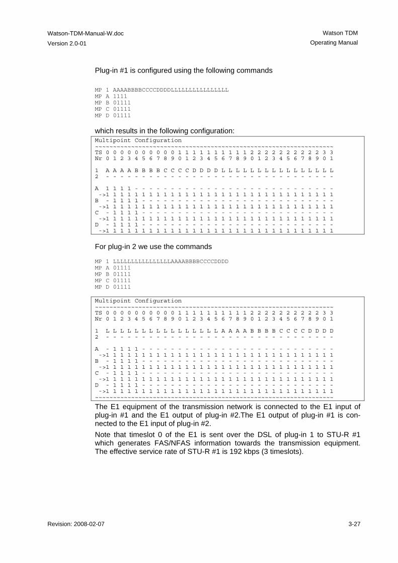
Watson-TDM-Manual-W.doc
Version 2.0-01
Watson TDM Operating Manual
Revision: 2008-02-07 3-27
Plug-in #1 is configured using the following commands MP 1 AAAABBBBCCCCDDDDLLLLLLLLLLLLLLLL MP A 1111 MP B 01111 MP C 01111 MP D 01111
which results in the following configuration: Multipoint Configuration ~~~~~~~~~~~~~~~~~~~~~~~~~~~~~~~~~~~~~~~~~~~~~~~~~~~~~~~~~~~~~~~~~~ TS 0 0 0 0 0 0 0 0 0 0 1 1 1 1 1 1 1 1 1 1 2 2 2 2 2 2 2 2 2 2 3 3 Nr 0 1 2 3 4 5 6 7 8 9 0 1 2 3 4 5 6 7 8 9 0 1 2 3 4 5 6 7 8 9 0 1 1 A A A A B B B B C C C C D D D D L L L L L L L L L L L L L L L L 2 - - - - - - - - - - - - - - - - - - - - - - - - - - - - - - - - A 1 1 1 1 - - - - - - - - - - - - - - - - - - - - - - - - - - - - ->1 1 1 1 1 1 1 1 1 1 1 1 1 1 1 1 1 1 1 1 1 1 1 1 1 1 1 1 1 1 1 1 B - 1 1 1 1 - - - - - - - - - - - - - - - - - - - - - - - - - - - ->1 1 1 1 1 1 1 1 1 1 1 1 1 1 1 1 1 1 1 1 1 1 1 1 1 1 1 1 1 1 1 1 C - 1 1 1 1 - - - - - - - - - - - - - - - - - - - - - - - - - - - ->1 1 1 1 1 1 1 1 1 1 1 1 1 1 1 1 1 1 1 1 1 1 1 1 1 1 1 1 1 1 1 1 D - 1 1 1 1 - - - - - - - - - - - - - - - - - - - - - - - - - - - ->1 1 1 1 1 1 1 1 1 1 1 1 1 1 1 1 1 1 1 1 1 1 1 1 1 1 1 1 1 1 1 1
For plug-in 2 we use the commands MP 1 LLLLLLLLLLLLLLLLAAAABBBBCCCCDDDD MP A 01111 MP B 01111 MP C 01111 MP D 01111 Multipoint Configuration ~~~~~~~~~~~~~~~~~~~~~~~~~~~~~~~~~~~~~~~~~~~~~~~~~~~~~~~~~~~~~~~~~~ TS 0 0 0 0 0 0 0 0 0 0 1 1 1 1 1 1 1 1 1 1 2 2 2 2 2 2 2 2 2 2 3 3 Nr 0 1 2 3 4 5 6 7 8 9 0 1 2 3 4 5 6 7 8 9 0 1 2 3 4 5 6 7 8 9 0 1 1 L L L L L L L L L L L L L L L L A A A A B B B B C C C C D D D D 2 - - - - - - - - - - - - - - - - - - - - - - - - - - - - - - - - A - 1 1 1 1 - - - - - - - - - - - - - - - - - - - - - - - - - - - ->1 1 1 1 1 1 1 1 1 1 1 1 1 1 1 1 1 1 1 1 1 1 1 1 1 1 1 1 1 1 1 1 B - 1 1 1 1 - - - - - - - - - - - - - - - - - - - - - - - - - - - ->1 1 1 1 1 1 1 1 1 1 1 1 1 1 1 1 1 1 1 1 1 1 1 1 1 1 1 1 1 1 1 1 C - 1 1 1 1 - - - - - - - - - - - - - - - - - - - - - - - - - - - ->1 1 1 1 1 1 1 1 1 1 1 1 1 1 1 1 1 1 1 1 1 1 1 1 1 1 1 1 1 1 1 1 D - 1 1 1 1 - - - - - - - - - - - - - - - - - - - - - - - - - - - ->1 1 1 1 1 1 1 1 1 1 1 1 1 1 1 1 1 1 1 1 1 1 1 1 1 1 1 1 1 1 1 1 ~~~~~~~~~~~~~~~~~~~~~~~~~~~~~~~~~~~~~~~~~~~~~~~~~~~~~~~~~~~~~~~~~~
The E1 equipment of the transmission network is connected to the E1 input of plug-in #1 and the E1 output of plug-in #2.The E1 output of plug-in #1 is con-nected to the E1 input of plug-in #2. Note that timeslot 0 of the E1 is sent over the DSL of plug-in 1 to STU-R #1 which generates FAS/NFAS information towards the transmission equipment. The effective service rate of STU-R #1 is 192 kbps (3 timeslots).
Watson TDM
Operating Manual
Watson-TDM-Manual-W.doc Version 2.0-01
3-28 Revision: 2008-02-07
3.7 Performance Monitoring
3.7.1 DSL Parameters The Watson TDM modems provide information about the current Signal Quality and Attenuation of a DSL link: The Signal Quality is the noise margin calculated by the modem:
SQ = SNR1 - SNR0 Where
SQ is the calculated noise margin SNR1 is the signal to noise ratio calculated by the transceiver by analyzing
the error correction bits (Trellis bits) in the line code. SNR0 is the signal to noise ratio that gives a bit error rate of 10-7 in presence
of average white Gassian noise. For TC-PAM16 the theoretical value for SNR0 is 27.7 dB.
The Attenuation is the link attenuation calculated by the modem, assuming 0.4mm PE cable without bridged taps and measured at 150 kHz (for linerates of 200 kbit/s up to 1'992 kbit/s) or 200 kHz (for linerates of 2'056 kbit/s and above). Note that the calculated attenuation may differ from the attenuation measured by other equipment for other cable configurations (other cable diameter, splices, bridged taps). Both Signal Quality and Attenuation are effective maintenance tools for determin-ing inadequate or bad cable pairs.
3.7.2 G.826 Performance Monitoring The G.826 error performance parameters provide quantitative performance in-formation of a specific link. They are intended to be used for long-term evaluation of operating DSL links. The evaluation of the G.826 error performance parameters is based on CRC (Cyclic Redundancy Check) error detection.
DSL Interface On the DSL side, six CRC6 check bits are generated per DSL frame for each channel and direction. The software counts block errors and evaluates the error performance according to ITU-T G.826 using these CRC6 bits.
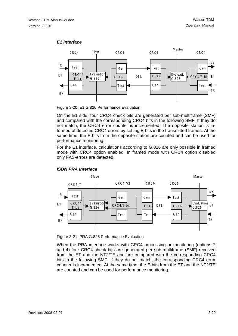
Watson-TDM-Manual-W.doc
Version 2.0-01
Watson TDM Operating Manual
Revision: 2008-02-07 3-29
E1 Interface
SlaveCRC4 CRC6
TX
RX
E1
Gen
CRC6 DSL
MasterCRC6 CRC4
Test
Gen.
CRC4/E-bit
Test
CRC6
TX
RX
E1
Test
Evaluation G.826
Evaluation G.826
Gen.
Test
CRC4/E-bit
Gen.
Figure 3-20: E1 G.826 Performance Evaluation
On the E1 side, four CRC4 check bits are generated per sub-multiframe (SMF) and compared with the corresponding CRC4 bits in the following SMF. If they do not match, the CRC4 error counter is incremented. The opposite station is in-formed of detected CRC4 errors by setting E-bits in the transmitted frames. At the same time, the E-bits from the opposite station are counted and can be used for performance monitoring. For the E1 interface, calculations according to G.826 are only possible in framed mode with CRC4 option enabled. In framed mode with CRC4 option disabled only FAS-errors are detected.
ISDN PRA Interface
CRC4_T CRC4_V3
TX
RX
E1
Gen.
CRC6 DSL
Master
CRC6
Test
Gen.
CRC6
TX
RX
E1
Test
Evaluation G.826
Evaluation G.826
Gen.
Test
CRC4/E-bit
Test
Gen.
CRC4/E-bit
CRC6
Slave
Figure 3-21: PRA G.826 Performance Evaluation
When the PRA interface works with CRC4 processing or monitoring (options 2 and 4) four CRC4 check bits are generated per sub-multiframe (SMF) received from the ET and the NT2/TE and are compared with the corresponding CRC4 bits in the following SMF. If they do not match, the corresponding CRC4 error counter is incremented. At the same time, the E-bits from the ET and the NT2/TE are counted and can be used for performance monitoring.
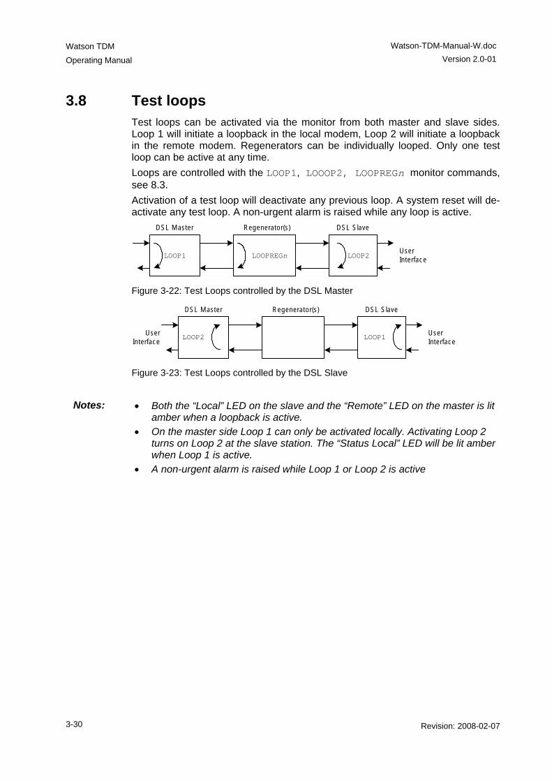
Watson TDM
Operating Manual
Watson-TDM-Manual-W.doc Version 2.0-01
3-30 Revision: 2008-02-07
3.8 Test loops Test loops can be activated via the monitor from both master and slave sides. Loop 1 will initiate a loopback in the local modem, Loop 2 will initiate a loopback in the remote modem. Regenerators can be individually looped. Only one test loop can be active at any time. Loops are controlled with the LOOP1, LOOOP2, LOOPREGn monitor commands, see 8.3. Activation of a test loop will deactivate any previous loop. A system reset will de-activate any test loop. A non-urgent alarm is raised while any loop is active.
DSL Master Regenerator(s) DSL Slave
User Interface
LOOPREGn LOOP2LOOP1
Figure 3-22: Test Loops controlled by the DSL Master
DSL Master Regenerator(s) DSL Slave
User Interface
User Interface
LOOP2 LOOP1
Figure 3-23: Test Loops controlled by the DSL Slave
Notes: • Both the “Local” LED on the slave and the “Remote” LED on the master is lit
amber when a loopback is active. • On the master side Loop 1 can only be activated locally. Activating Loop 2
turns on Loop 2 at the slave station. The “Status Local” LED will be lit amber when Loop 1 is active.
• A non-urgent alarm is raised while Loop 1 or Loop 2 is active
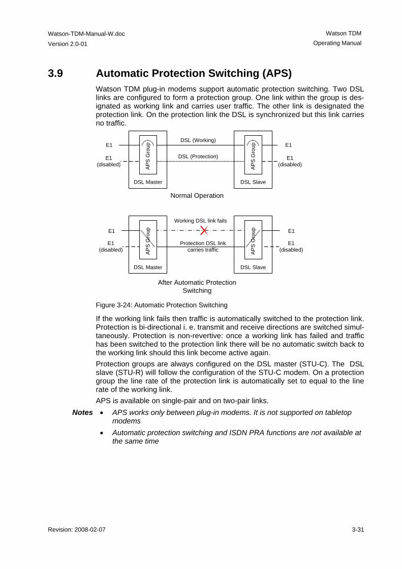
Watson-TDM-Manual-W.doc
Version 2.0-01
Watson TDM Operating Manual
Revision: 2008-02-07 3-31
3.9 Automatic Protection Switching (APS) Watson TDM plug-in modems support automatic protection switching. Two DSL links are configured to form a protection group. One link within the group is des-ignated as working link and carries user traffic. The other link is designated the protection link. On the protection link the DSL is synchronized but this link carries no traffic.
DSL Master
E1
E1 (disabled)
DSL Slave
DSL (Working)
DSL (Protection)
E1
E1 (disabled)
DSL Master
E1
E1 (disabled)
DSL Slave
Working DSL link fails
Protection DSL link carries traffic
E1
E1 (disabled)
Normal Operation
After Automatic Protection Switching
APS
Gro
up
APS
Gro
upAP
S G
roup
APS
Gro
up
Figure 3-24: Automatic Protection Switching
If the working link fails then traffic is automatically switched to the protection link. Protection is bi-directional i. e. transmit and receive directions are switched simul-taneously. Protection is non-revertive: once a working link has failed and traffic has been switched to the protection link there will be no automatic switch back to the working link should this link become active again. Protection groups are always configured on the DSL master (STU-C). The DSL slave (STU-R) will follow the configuration of the STU-C modem. On a protection group the line rate of the protection link is automatically set to equal to the line rate of the working link. APS is available on single-pair and on two-pair links.
Notes • APS works only between plug-in modems. It is not supported on tabletop modems
• Automatic protection switching and ISDN PRA functions are not available at the same time
Watson TDM
Operating Manual
Watson-TDM-Manual-W.doc Version 2.0-01
3-32 Revision: 2008-02-07
3.10 Password Protection On tabletop modems the access to the Monitor can be protected by a password to avoid unauthorized reconfiguration of modems installed at the customer site. While in protected mode it is required to enter a password before any Monitor command can be executed from a terminal connected to the local RS-232 port of the modem. Password protection is only active on the local RS-232 port. There is no pass-word protection when accessing the modem through the DSL EOC. This allows to reset the password of a protected modem configured as STU-R (DSL slave) from the STU-C (DSL master). One command is allowed without entering a password while password protection is active: the DSLSLAVE command. DSLSLAVE configures a modem from DSL master to DSL slave. If the password of a modem configured as DSL master has been lost then this modem can be reconfigured as DSL slave with DSLSLAVE, allowing to reset the password through the DSL EOC.
Notes: • Password commands through the DSL EOC are not possible if the ACU48 is present in the subrack.
• Password commands are only available on tabletop modems • Password protection is disabled by default.
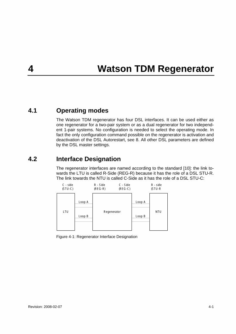
Revision: 2008-02-07 4-1
4 Watson TDM Regenerator
4.1 Operating modes The Watson TDM regenerator has four DSL interfaces. It can be used either as one regenerator for a two-pair system or as a dual regenerator for two independ-ent 1-pair systems. No configuration is needed to select the operating mode. In fact the only configuration command possible on the regenerator is activation and deactivation of the DSL Autorestart, see 8. All other DSL parameters are defined by the DSL master settings.
4.2 Interface Designation The regenerator interfaces are named according to the standard [10]: the link to-wards the LTU is called R-Side (REG-R) because it has the role of a DSL STU-R. The link towards the NTU is called C-Side as it has the role of a DSL STU-C:
LTU Regenerator NTU
C - side(STU-C)
R - side(STU-R
R - Side(REG-R)
C - Side(REG-C)
Loop A
Loop B
Loop A
Loop B
Figure 4-1: Regenerator Interface Designation
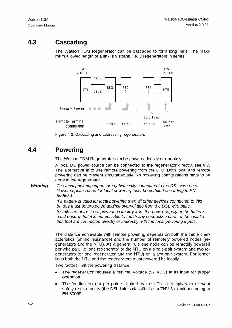
Watson TDM
Operating Manual
Watson-TDM-Manual-W.doc Version 2.0-01
4-2 Revision: 2008-02-07
4.3 Cascading The Watson TDM Regenerator can be cascaded to form long links. The maxi-mum allowed length of a link is 9 spans, i.e. 8 regenerators in series:
...LTU
DSL A
DSL B
C-Side(STU-C)
R-Side(STU-R)
REG1
Remote Power
Remote Terminal connection
CON 3 CON 4CON 2 or
CON
REG2
NTU REG
8
CON 10
Local Power
Figure 4-2: Cascading and addressing regenerators
4.4 Powering The Watson TDM Regenerator can be powered locally or remotely. A local DC power source can be connected to the regenerator directly, see 9.7. The alternative is to use remote powering from the LTU. Both local and remote powering can be present simultaneously. No powering configurations have to be done in the regenerator.
Warning The local powering inputs are galvanically connected to the DSL wire pairs. Power supplies used for local powering must be certified according to EN 60950-1. If a battery is used for local powering then all other devices connected to this battery must be protected against overvoltage from the DSL wire pairs. Installation of the local powering circuitry from the power supply or the battery must ensure that it is not possible to touch any conductive parts of the installa-tion that are connected directly or indirectly with the local powering inputs.
The distance achievable with remote powering depends on both the cable char-acteristics (ohmic resistance) and the number of remotely powered nodes (re-generators and the NTU). As a general rule one node can be remotely powered per wire pair, i.e. one regenerator or the NTU on a single-pair system and two re-generators (or one regenerator and the NTU) on a two-pair system. For longer links both the NTU and the regenerators must powered be locally. Two factors limit the powering distance: • The regenerator requires a minimal voltage (57 VDC) at its input for proper
operation • The feeding current per pair is limited by the LTU to comply with relevant
safety requirements (the DSL link is classified as a TNV-3 circuit according to EN 30069.
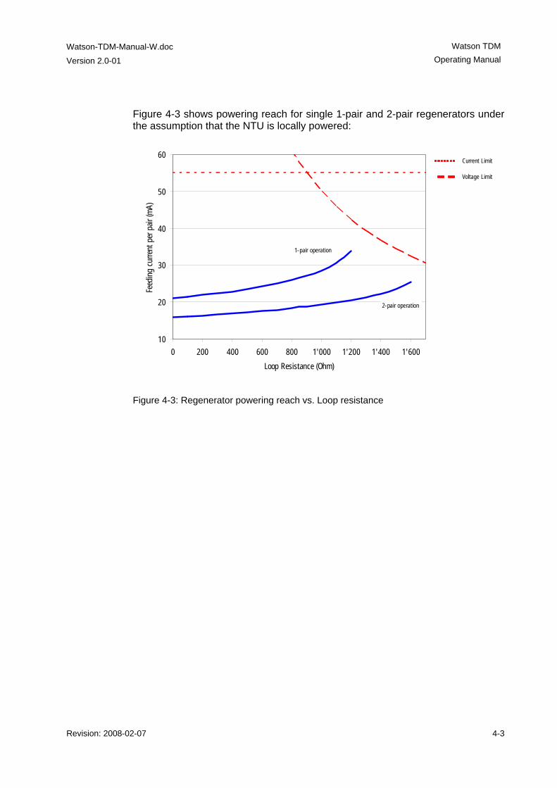
Watson-TDM-Manual-W.doc
Version 2.0-01
Watson TDM Operating Manual
Revision: 2008-02-07 4-3
Figure 4-3 shows powering reach for single 1-pair and 2-pair regenerators under the assumption that the NTU is locally powered:
10
20
30
40
50
60
0 200 400 600 800 1'000 1'200 1'400 1'600
Loop Resistance (Ohm)
Feed
ing
curre
nt p
er p
air (
mA)
2-pair operation
1-pair operation
Current Limit
Voltage Limit
Figure 4-3: Regenerator powering reach vs. Loop resistance

Revision: 2008-02-07 5-1
5 Powering
5.1 Plug-in Each plug-in is fed via subrack backplane with (dual) -48VDC (referenced to 0VDC of the exchange battery). The minirack mechanics has two -48VDC inputs and on model SZ.876.V100 also an AC powering input. The plug-in generates the used voltages onboard. The ground reference of all voltages on the secondary side of the plug-in DC/DC-converter is tied to FPE (Functional Protective Earth). Additionally, the plug-in is fed over the backplane with an auxiliary +5VDC supply (referenced to ground) generated on the ACU. The only purpose of this voltage is to drive the alarm circuitry on each plug-in, even in the case of a failure of the plug-in onboard DC/DC-converter.
5.2 Tabletop
5.2.1 Power and Grounding The ground of a tabletop modem is normally floating when referenced to earth. If a tabletop modem is equipped with an E1 or nx64 kbit/s user interface, the shields / signal ground of the cables are coupled to the ground of the modem. On tabletop modems a ground connector is available on the rear panel of the mo-dem. A slide switch located on the rear of the housing selects the power source of the tabletop unit (remote powering over the DSL line or local powering by an external 48VDC source). The position of the switch can be changed with a small screwdriver. Before oper-ating the switch, the DSL line connector and the mains adapter connector must be removed.
Caution: Switching from local to remote powering leads to an interruption of the DSL link. Before changing the position of the powering switch the tabletop must be switched off and disconnected from the DSL line.
Watson TDM
Operating Manual
Watson-TDM-Manual-W.doc Version 2.0-01
5-2 Revision: 2008-02-07
Caution: Only power sources below maximum hazardous energy levels according IEC 60950-1 chapter 1.2.8.10 may be used as local power source. The insulation voltage of the power source must support elevated insulation voltage according to EN 60950-1 (at least 4 KV insulation). The power adapters available from Schmid Telecom fulfill these requirements.
Caution: Do not connect a 48VDC supply directly to the “AC/DC adapter” connector! High voltage transients from the DSL line may damage other equipment connected to the battery. A DC/DC converter with 4kV transient isolation voltage should be used in this case and the ground connector on the tabletop modem should be connected to ground.
Caution: The local supply voltage input is protected against reversal of polarity but not fused. Appropriate fusing has to be done externally.
5.3 Remote Powering Watson TDM supports the line powering concept of SHDSL. Plug-ins can supply remote power over the DSL copper pairs. Tabletop modems and Regenerators can be remotely powered over these copper pairs. Remote powering is available on all pairs of a multipair system.
5.3.1 Remote power feeding on plug-ins Plug-ins are equipped with a remote powering circuits with the following charac-teristics: • Per pair remote power feed • Cross-wiring tolerant • Power feeding voltage within limits of EN 60950 TNV-3 • Independent current limiters on a per pair basis (microcontroller - controlled) • Tolerant against micro-interruptions • Automatic system restart after power failure Remote powering is controlled through the POWER command of the monitor. The remote powering circuit is protected against overvoltage and overcurrent, see 11.1.1. In case of overvoltage or overcurrent the powering is disconnected within less than 700ms.
Note: During the power-up phase of the plug-in the disconnect delay can be up to 900 ms.
When remote powering was disconnected by overcurrent protection then it is switched on automatically after 10 seconds. When remote powering was disconnected by overvoltage protection then it will disconnected until a hardware reset is done on the plug-in (removal of the plug-in from the subrack). In this state the plug-in LEDs 1 and 3 will be red blinking and no monitor access is possible. The overvoltage protection is only activated by se-rious hardware faults in the feeding circuit which require analysis and repair by the manufacturer.
Watson-TDM-Manual-W.doc
Version 2.0-01
Watson TDM Operating Manual
Revision: 2008-02-07 5-3
Note: If a remotely powered tabletop modem consumes more power than can be fed over the DSL link then it will not start up properly. This can lead to the loss of a remote modem through misconfiguration, e.g. by enabling the nx64 interface on a multiservice modem which is operating at the power limit with the nx64 inter-face switched off. With such reconfigurations the power consumption of the mo-dem increases and it will not work properly anymore, making it impossible to get back to a working configuration under remote control. In such cases manual in-tervention at the site of the remote modem is required to reconfigure the unit with a local terminal.
The reach attainable with remote powering depends on the power consumption of the modem and on the loop resistance (wire diameter and cable length and re-sistance of the feeding/protection circuitry in the plug-in).
5.3.2 Remote powering of Tabletops The tabletops have a backplane switch to select local or remote powering. In the default switch position "REM" the tabletop modem is powered via the DSL line and will start operation immediately after connection of the DSL line. In position "LOC", the tabletop modem is powered locally and needs to be connected to a power supply to operate.
5.3.3 Powering Status Display The current powering status of a tabletop modem is available in the STATUS dis-play of the monitor (Unit Power Source UPS): UPS = 01 for local powering UPS = 02 for remote powering
5.3.4 Power Failure Alarm The power supply bit fbit3 of the DSL frame is used to indicate the status of the local power supply in the tabletop modem. The power status bit is set to ONE if power is normal and to ZERO if the power has failed. In case of power loss at the remote modem there is enough power left to communicate three "Power Loss" messages towards the LTU. In case of a failure of the tabletop modem power supply, both LEDs will be extinguished.
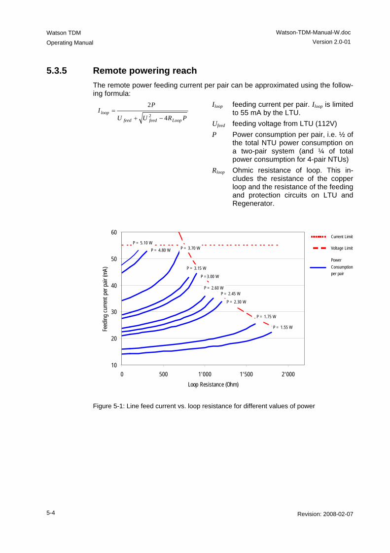
Watson TDM
Operating Manual
Watson-TDM-Manual-W.doc Version 2.0-01
5-4 Revision: 2008-02-07
5.3.5 Remote powering reach The remote power feeding current per pair can be approximated using the follow-ing formula:
PRUU
PI
Loopfeedfeed
loop4
22 −+
= Iloop feeding current per pair. Iloop is limited
to 55 mA by the LTU. Ufeed feeding voltage from LTU (112V) P Power consumption per pair, i.e. ½ of
the total NTU power consumption on a two-pair system (and ¼ of total power consumption for 4-pair NTUs)
Rloop Ohmic resistance of loop. This in-cludes the resistance of the copper loop and the resistance of the feeding and protection circuits on LTU and Regenerator.
10
20
30
40
50
60
0 500 1'000 1'500 2'000
Loop Resistance (Ohm)
Feed
ing
curre
nt p
er p
air (
mA)
P = 1.55 W
P = 1.75 W
P = 2.30 W
P = 2.60 W
P =3.00 W
P = 3.15 W
P = 3.70 WP = 4.80 W
P = 5.10 WCurrent Limit
Voltage Limit
P = 2.45 W
Power
Consumption
per pair
Figure 5-1: Line feed current vs. loop resistance for different values of power
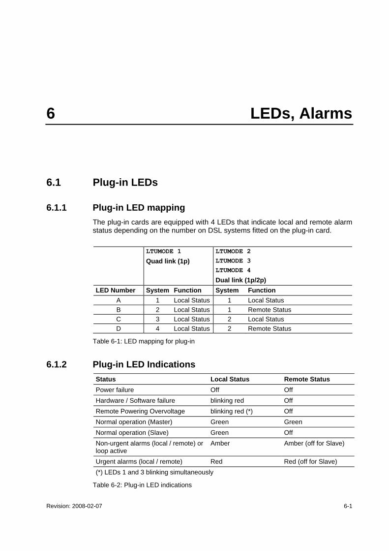
Revision: 2008-02-07 6-1
6 LEDs, Alarms
6.1 Plug-in LEDs
6.1.1 Plug-in LED mapping The plug-in cards are equipped with 4 LEDs that indicate local and remote alarm status depending on the number on DSL systems fitted on the plug-in card. LTUMODE 1
Quad link (1p) LTUMODE 2 LTUMODE 3 LTUMODE 4
Dual link (1p/2p) LED Number System Function System Function
A 1 Local Status 1 Local Status B 2 Local Status 1 Remote Status C 3 Local Status 2 Local Status D 4 Local Status 2 Remote Status
Table 6-1: LED mapping for plug-in
6.1.2 Plug-in LED Indications Status Local Status Remote Status Power failure Off Off Hardware / Software failure blinking red Off Remote Powering Overvoltage blinking red (*) Off Normal operation (Master) Green Green Normal operation (Slave) Green Off Non-urgent alarms (local / remote) or loop active
Amber Amber (off for Slave)
Urgent alarms (local / remote) Red Red (off for Slave) (*) LEDs 1 and 3 blinking simultaneously
Table 6-2: Plug-in LED indications
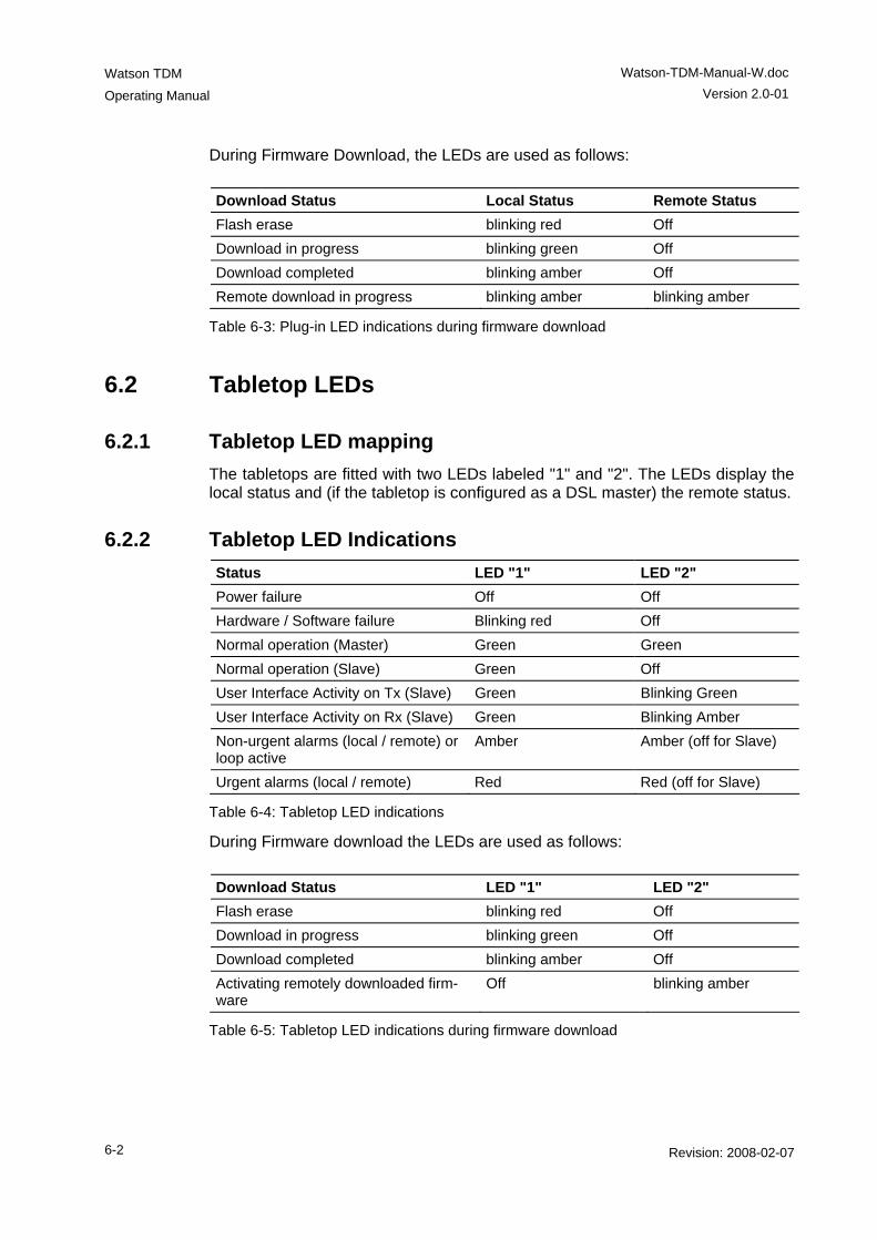
Watson TDM
Operating Manual
Watson-TDM-Manual-W.doc Version 2.0-01
6-2 Revision: 2008-02-07
During Firmware Download, the LEDs are used as follows:
Download Status Local Status Remote Status Flash erase blinking red Off Download in progress blinking green Off Download completed blinking amber Off Remote download in progress blinking amber blinking amber
Table 6-3: Plug-in LED indications during firmware download
6.2 Tabletop LEDs
6.2.1 Tabletop LED mapping The tabletops are fitted with two LEDs labeled "1" and "2". The LEDs display the local status and (if the tabletop is configured as a DSL master) the remote status.
6.2.2 Tabletop LED Indications Status LED "1" LED "2" Power failure Off Off Hardware / Software failure Blinking red Off Normal operation (Master) Green Green Normal operation (Slave) Green Off User Interface Activity on Tx (Slave) Green Blinking Green User Interface Activity on Rx (Slave) Green Blinking Amber Non-urgent alarms (local / remote) or loop active
Amber Amber (off for Slave)
Urgent alarms (local / remote) Red Red (off for Slave)
Table 6-4: Tabletop LED indications
During Firmware download the LEDs are used as follows:
Download Status LED "1" LED "2" Flash erase blinking red Off Download in progress blinking green Off Download completed blinking amber Off Activating remotely downloaded firm-ware
Off blinking amber
Table 6-5: Tabletop LED indications during firmware download
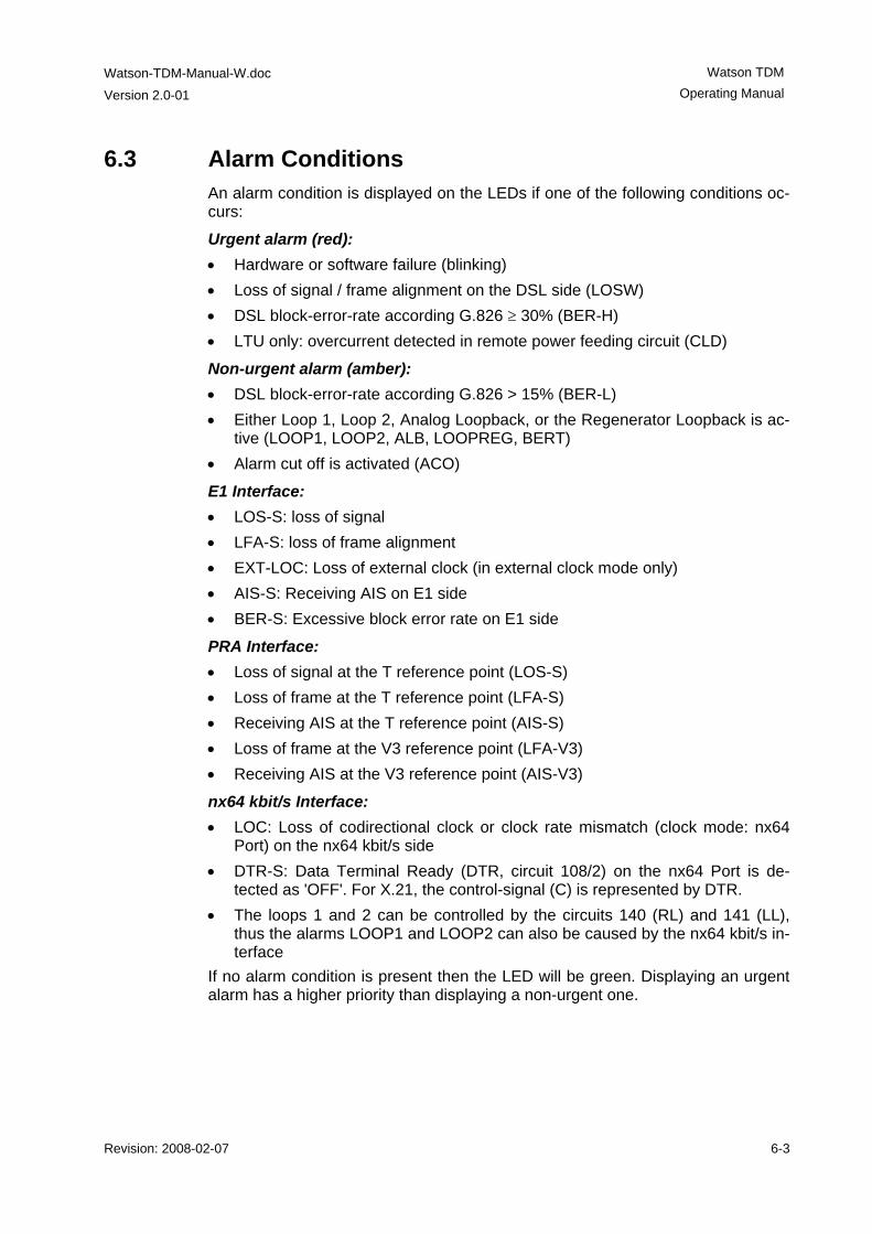
Watson-TDM-Manual-W.doc
Version 2.0-01
Watson TDM Operating Manual
Revision: 2008-02-07 6-3
6.3 Alarm Conditions An alarm condition is displayed on the LEDs if one of the following conditions oc-curs:
Urgent alarm (red): • Hardware or software failure (blinking) • Loss of signal / frame alignment on the DSL side (LOSW) • DSL block-error-rate according G.826 ≥ 30% (BER-H) • LTU only: overcurrent detected in remote power feeding circuit (CLD)
Non-urgent alarm (amber): • DSL block-error-rate according G.826 > 15% (BER-L) • Either Loop 1, Loop 2, Analog Loopback, or the Regenerator Loopback is ac-
tive (LOOP1, LOOP2, ALB, LOOPREG, BERT) • Alarm cut off is activated (ACO)
E1 Interface: • LOS-S: loss of signal • LFA-S: loss of frame alignment • EXT-LOC: Loss of external clock (in external clock mode only) • AIS-S: Receiving AIS on E1 side • BER-S: Excessive block error rate on E1 side
PRA Interface: • Loss of signal at the T reference point (LOS-S) • Loss of frame at the T reference point (LFA-S) • Receiving AIS at the T reference point (AIS-S) • Loss of frame at the V3 reference point (LFA-V3) • Receiving AIS at the V3 reference point (AIS-V3)
nx64 kbit/s Interface: • LOC: Loss of codirectional clock or clock rate mismatch (clock mode: nx64
Port) on the nx64 kbit/s side • DTR-S: Data Terminal Ready (DTR, circuit 108/2) on the nx64 Port is de-
tected as 'OFF'. For X.21, the control-signal (C) is represented by DTR. • The loops 1 and 2 can be controlled by the circuits 140 (RL) and 141 (LL),
thus the alarms LOOP1 and LOOP2 can also be caused by the nx64 kbit/s in-terface
If no alarm condition is present then the LED will be green. Displaying an urgent alarm has a higher priority than displaying a non-urgent one.
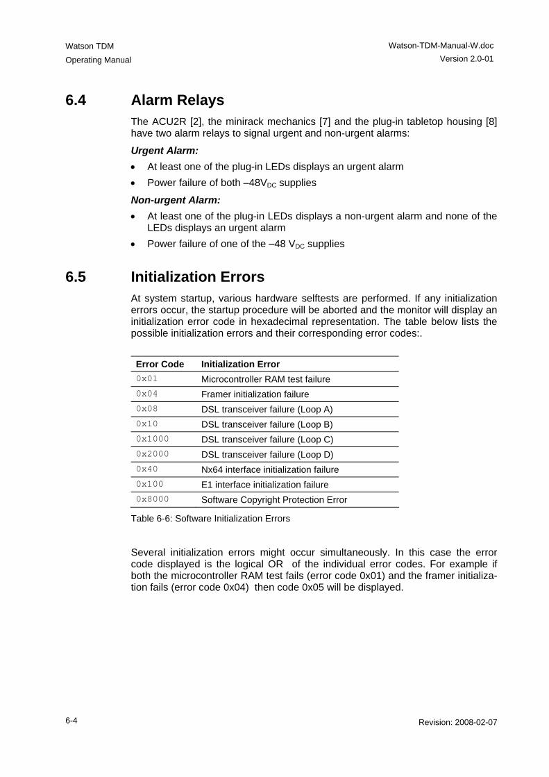
Watson TDM
Operating Manual
Watson-TDM-Manual-W.doc Version 2.0-01
6-4 Revision: 2008-02-07
6.4 Alarm Relays The ACU2R [2], the minirack mechanics [7] and the plug-in tabletop housing [8] have two alarm relays to signal urgent and non-urgent alarms:
Urgent Alarm: • At least one of the plug-in LEDs displays an urgent alarm • Power failure of both –48VDC supplies
Non-urgent Alarm: • At least one of the plug-in LEDs displays a non-urgent alarm and none of the
LEDs displays an urgent alarm • Power failure of one of the –48 VDC supplies
6.5 Initialization Errors At system startup, various hardware selftests are performed. If any initialization errors occur, the startup procedure will be aborted and the monitor will display an initialization error code in hexadecimal representation. The table below lists the possible initialization errors and their corresponding error codes:. Error Code Initialization Error 0x01 Microcontroller RAM test failure 0x04 Framer initialization failure 0x08 DSL transceiver failure (Loop A) 0x10 DSL transceiver failure (Loop B) 0x1000 DSL transceiver failure (Loop C) 0x2000 DSL transceiver failure (Loop D) 0x40 Nx64 interface initialization failure 0x100 E1 interface initialization failure 0x8000 Software Copyright Protection Error
Table 6-6: Software Initialization Errors
Several initialization errors might occur simultaneously. In this case the error code displayed is the logical OR of the individual error codes. For example if both the microcontroller RAM test fails (error code 0x01) and the framer initializa-tion fails (error code 0x04) then code 0x05 will be displayed.
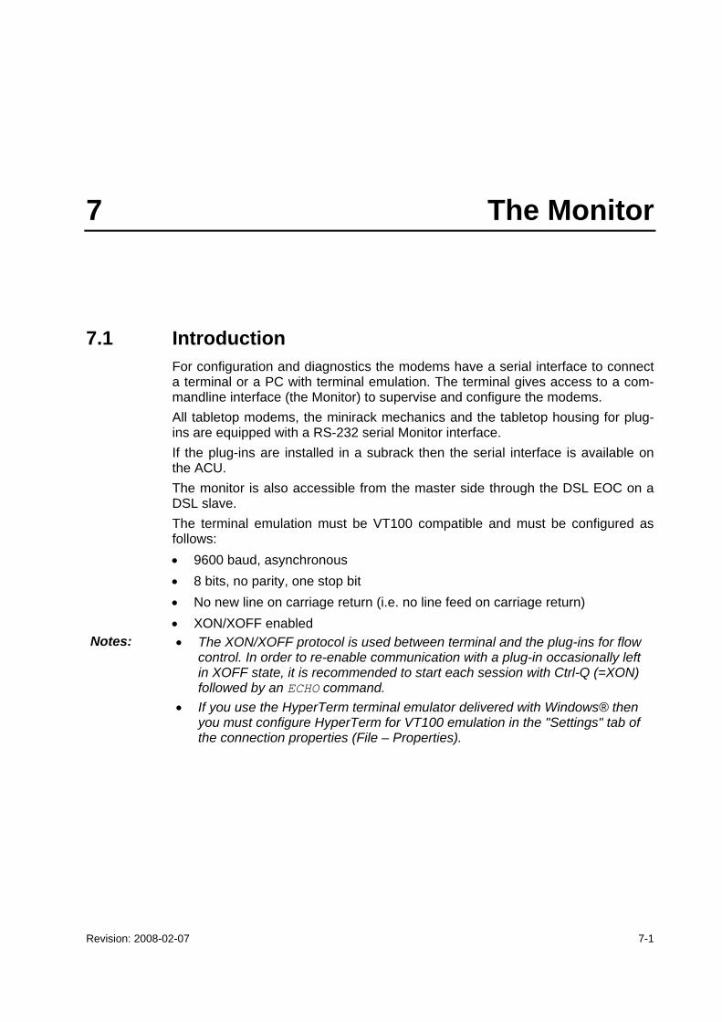
Revision: 2008-02-07 7-1
7 The Monitor
7.1 Introduction For configuration and diagnostics the modems have a serial interface to connect a terminal or a PC with terminal emulation. The terminal gives access to a com-mandline interface (the Monitor) to supervise and configure the modems. All tabletop modems, the minirack mechanics and the tabletop housing for plug-ins are equipped with a RS-232 serial Monitor interface. If the plug-ins are installed in a subrack then the serial interface is available on the ACU. The monitor is also accessible from the master side through the DSL EOC on a DSL slave. The terminal emulation must be VT100 compatible and must be configured as follows: • 9600 baud, asynchronous • 8 bits, no parity, one stop bit • No new line on carriage return (i.e. no line feed on carriage return) • XON/XOFF enabled
Notes: • The XON/XOFF protocol is used between terminal and the plug-ins for flow control. In order to re-enable communication with a plug-in occasionally left in XOFF state, it is recommended to start each session with Ctrl-Q (=XON) followed by an ECHO command.
• If you use the HyperTerm terminal emulator delivered with Windows® then you must configure HyperTerm for VT100 emulation in the "Settings" tab of the connection properties (File – Properties).
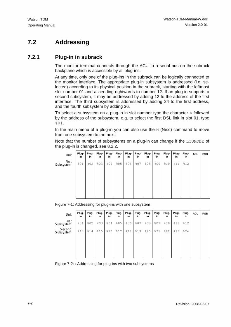
Watson TDM
Operating Manual
Watson-TDM-Manual-W.doc Version 2.0-01
7-2 Revision: 2008-02-07
7.2 Addressing
7.2.1 Plug-in in subrack The monitor terminal connects through the ACU to a serial bus on the subrack backplane which is accessible by all plug-ins. At any time, only one of the plug-ins in the subrack can be logically connected to the monitor interface. The appropriate plug-in subsystem is addressed (i.e. se-lected) according to its physical position in the subrack, starting with the leftmost slot number 01 and ascending rightwards to number 12. If an plug-in supports a second subsystem, it may be addressed by adding 12 to the address of the first interface. The third subsystem is addressed by adding 24 to the first address, and the fourth subsystem by adding 36. To select a subsystem on a plug-in in slot number type the character % followed by the address of the subsystem, e.g. to select the first DSL link in slot 01, type %01. In the main menu of a plug-in you can also use the N (Next) command to move from one subsystem to the next. Note that the number of subsystems on a plug-in can change if the LTUMODE of the plug-in is changed, see 8.2.2.
Plug-in
%01
Plug-in
%02
Plug-in
%03
Plug-in
%04
Plug-in
%05
Plug-in
%06
Plug-in
%07
Plug-in
%08
Plug-in
%09
Plug-in
%10
Plug-in
%11
Plug-in
%12
ACU PSB
First Subsystem
Unit
Figure 7-1: Addressing for plug-ins with one subsystem
Plug-in
%01
%13
Plug-in
%02
%14
Plug-in
%03
%15
Plug-in
%04
%16
Plug-in
%05
%17
Plug-in
%06
%18
Plug-in
%07
%19
Plug-in
%08
%20
Plug-in
%09
%21
Plug-in
%10
%22
Plug-in
%11
%23
Plug-in
%12
%24
ACU PSB
First Subsystem
Second Subsystem
Unit
Figure 7-2: : Addressing for plug-ins with two subsystems
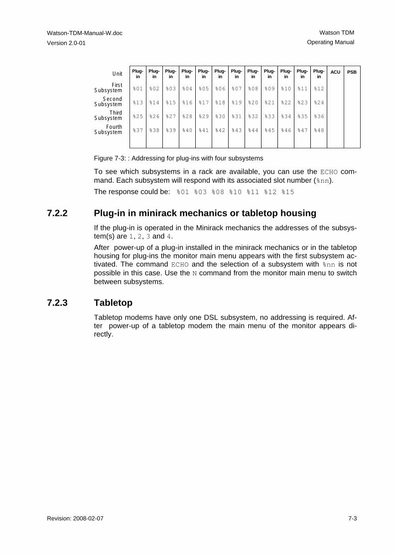
Watson-TDM-Manual-W.doc
Version 2.0-01
Watson TDM Operating Manual
Revision: 2008-02-07 7-3
Plug-in
%01
%13
%25
%37
Plug-in
%02
%14
%26
%38
Plug-in
%03
%15
%27
%39
Plug-in
%04
%16
%28
%40
Plug-in
%05
%17
%29
%41
Plug-in
%06
%18
%30
%42
Plug-in
%07
%19
%31
%43
Plug-in
%08
%20
%32
%44
Plug-in
%09
%21
%33
%45
Plug-in
%10
%22
%34
%46
Plug-in
%11
%23
%35
%47
Plug-in
%12
%24
%36
%48
ACU PSB
First Subsystem
Second Subsystem
Third Subsystem
Fourth Subsystem
Unit
Figure 7-3: : Addressing for plug-ins with four subsystems
To see which subsystems in a rack are available, you can use the ECHO com-mand. Each subsystem will respond with its associated slot number (%nn). The response could be: %01 %03 %08 %10 %11 %12 %15
7.2.2 Plug-in in minirack mechanics or tabletop housing If the plug-in is operated in the Minirack mechanics the addresses of the subsys-tem(s) are 1, 2, 3 and 4. After power-up of a plug-in installed in the minirack mechanics or in the tabletop housing for plug-ins the monitor main menu appears with the first subsystem ac-tivated. The command ECHO and the selection of a subsystem with %nn is not possible in this case. Use the N command from the monitor main menu to switch between subsystems.
7.2.3 Tabletop Tabletop modems have only one DSL subsystem, no addressing is required. Af-ter power-up of a tabletop modem the main menu of the monitor appears di-rectly.
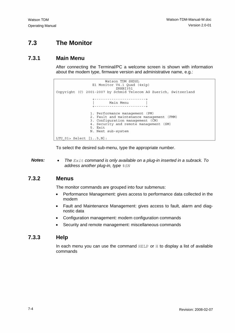
Watson TDM
Operating Manual
Watson-TDM-Manual-W.doc Version 2.0-01
7-4 Revision: 2008-02-07
7.3 The Monitor
7.3.1 Main Menu After connecting the Terminal/PC a welcome screen is shown with information about the modem type, firmware version and administrative name, e.g.: Watson TDM SHDSL E1 Monitor V4.1 Quad (4x1p) ZRHBI351 Copyright (C) 2001-2007 by Schmid Telecom AG Zuerich, Switzerland +------------------------+ | Main Menu | +------------------------+ 1. Performance management (PM) 2. Fault and maintenance management (FMM) 3. Configuration management (CM) 4. Security and remote management (SM) 5. Exit N. Next sub-system LTU_01> Select [1..5,N]:
To select the desired sub-menu, type the appropriate number.
Notes: • The Exit command is only available on a plug-in inserted in a subrack. To address another plug-in, type %SN
7.3.2 Menus The monitor commands are grouped into four submenus: • Performance Management: gives access to performance data collected in the
modem • Fault and Maintenance Management: gives access to fault, alarm and diag-
nostic data • Configuration management: modem configuration commands • Security and remote management: miscellaneous commands
7.3.3 Help In each menu you can use the command HELP or H to display a list of available commands
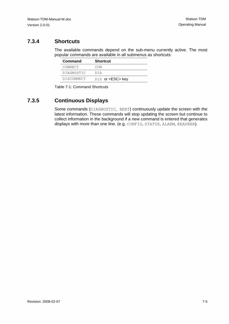
Watson-TDM-Manual-W.doc
Version 2.0-01
Watson TDM Operating Manual
Revision: 2008-02-07 7-5
7.3.4 Shortcuts The available commands depend on the sub-menu currently active. The most popular commands are available in all submenus as shortcuts:
Command Shortcut CONNECT CON
DIAGNOSTIC DIA
DISCONNECT DIS or <ESC> key
Table 7-1: Command Shortcuts
7.3.5 Continuous Displays Some commands (DIAGNOSTIC, BERT) continuously update the screen with the latest information. These commands will stop updating the screen but continue to collect information in the background if a new command is entered that generates displays with more than one line. (e.g. CONFIG, STATUS, ALARM, READBER).

Revision: 2008-02-07 8-1
8 Monitor Command Reference
8.1 Introduction This chapter defines the Monitor command language. The language is made up of the following elements: COMMAND Commands are written in CAPITALS KEYWORD Keywords are written in CAPITALS Parameter Parameters are written in Italics. Replace the
parameter with the actual value. Example: LINERATE n
Parameter | Parameter KEYWORD | KEYWORD
Choices are denoted with vertical bars |. In a choice group one of the parameters must be specified.
[ Parameter ] [ KEYWORD ]
Optional parameters are enclosed in [ brack-ets ]. Optional parameters can be specified but are not required.
Table 8-1: Command language elements
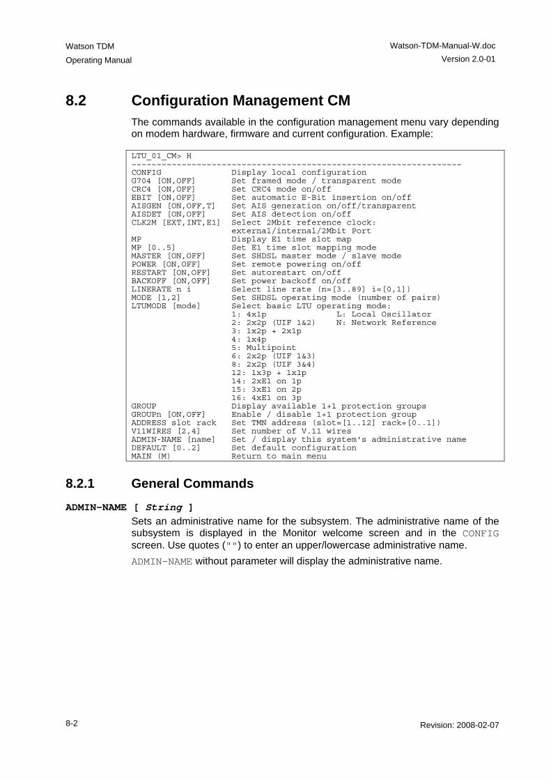
Watson TDM
Operating Manual
Watson-TDM-Manual-W.doc Version 2.0-01
8-2 Revision: 2008-02-07
8.2 Configuration Management CM The commands available in the configuration management menu vary depending on modem hardware, firmware and current configuration. Example: LTU_01_CM> H ~~~~~~~~~~~~~~~~~~~~~~~~~~~~~~~~~~~~~~~~~~~~~~~~~~~~~~~~~~~~~~~~~~ CONFIG Display local configuration G704 [ON,OFF] Set framed mode / transparent mode CRC4 [ON,OFF] Set CRC4 mode on/off EBIT [ON,OFF] Set automatic E-Bit insertion on/off AISGEN [ON,OFF,T] Set AIS generation on/off/transparent AISDET [ON,OFF] Set AIS detection on/off CLK2M [EXT,INT,E1] Select 2Mbit reference clock: external/internal/2Mbit Port MP Display E1 time slot map MP [0..5] Set E1 time slot mapping mode MASTER [ON,OFF] Set SHDSL master mode / slave mode POWER [ON,OFF] Set remote powering on/off RESTART [ON,OFF] Set autorestart on/off BACKOFF [ON,OFF] Set power backoff on/off LINERATE n i Select line rate (n=[3..89] i=[0,1]) MODE [1,2] Set SHDSL operating mode (number of pairs) LTUMODE [mode] Select basic LTU operating mode: 1: 4x1p L: Local Oscillator 2: 2x2p (UIF 1&2) N: Network Reference 3: 1x2p + 2x1p 4: 1x4p 5: Multipoint 6: 2x2p (UIF 1&3) 8: 2x2p (UIF 3&4) 12: 1x3p + 1x1p 14: 2xE1 on 1p 15: 3xE1 on 2p 16: 4xE1 on 3p GROUP Display available 1+1 protection groups GROUPn [ON,OFF] Enable / disable 1+1 protection group ADDRESS slot rack Set TMN address (slot=[1..12] rack=[0..1]) V11WIRES [2,4] Set number of V.11 wires ADMIN-NAME [name] Set / display this system's administrative name DEFAULT [0..2] Set default configuration MAIN (M) Return to main menu
8.2.1 General Commands
ADMIN-NAME [ String ] Sets an administrative name for the subsystem. The administrative name of the subsystem is displayed in the Monitor welcome screen and in the CONFIG screen. Use quotes ("") to enter an upper/lowercase administrative name. ADMIN-NAME without parameter will display the administrative name.
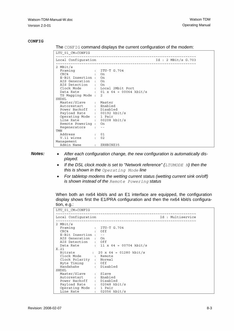
Watson-TDM-Manual-W.doc
Version 2.0-01
Watson TDM Operating Manual
Revision: 2008-02-07 8-3
CONFIG The CONFIG command displays the current configuration of the modem: LTU_01_CM>CONFIG ~~~~~~~~~~~~~~~~~~~~~~~~~~~~~~~~~~~~~~~~~~~~~~~~~~~~~~~~~~~~~~~~~~ Local Configuration Id : 2 MBit/s G.703 ~~~~~~~~~~~~~~~~~~~~~~~~~~~~~~~~~~~~~~~~~~~~~~~~~~~~~~~~~~~~~~~~~~ 2 MBit/s Framing : ITU-T G.704 CRC4 : On E-Bit Insertion : On AIS Generation : On AIS Detection : On Clock Mode : Local 2Mbit Port Data Rate : 01 x 64 = 00064 kbit/s TS Mapping Mode : 2 SHDSL Master/Slave : Master Autorestart : Enabled Power Backoff : Disabled Payload Rate : 00192 kbit/s Operating Mode : 1 Pair Line Rate : 00208 kbit/s Remote Powering : On Regenerators : -- TMN Address : 01 V.11 wires : 02 Management Admin Name : ZRHBINZ35
Notes: • After each configuration change, the new configuration is automatically dis-played.
• If the DSL clock mode is set to "Network reference" (LTUMODE N) then the this is shown in the Operating Mode line
• For tabletop modems the wetting current status (wetting current sink on/off) is shown instead of the Remote Powering status
When both an nx64 kbit/s and an E1 interface are equipped, the configuration display shows first the E1/PRA configuration and then the nx64 kbit/s configura-tion, e.g.: LTU_01_CM>CONFIG ~~~~~~~~~~~~~~~~~~~~~~~~~~~~~~~~~~~~~~~~~~~~~~~~~~~~~~~~~~~~~~~~~~ Local Configuration Id : Multiservice ~~~~~~~~~~~~~~~~~~~~~~~~~~~~~~~~~~~~~~~~~~~~~~~~~~~~~~~~~~~~~~~~~~ 2 MBit/s Framing : ITU-T G.704 CRC4 : Off E-Bit Insertion : -- AIS Generation : On AIS Detection : Off Data Rate : 11 x 64 = 00704 kbit/s X.21 Bitrate : 20 x 64 = 01280 kbit/s Clock Mode : Remote Clock Polarity : Normal Byte Timing : Off Handshake : Disabled SHDSL Master/Slave : Slave Autorestart : Enabled Power Backoff : Disabled Payload Rate : 02048 kbit/s Operating Mode : 1 Pair Line Rate : 02056 kbit/s
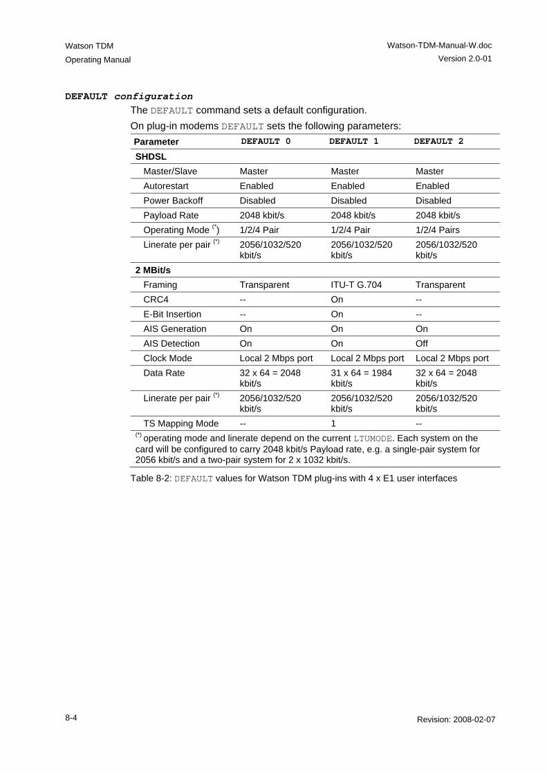
Watson TDM
Operating Manual
Watson-TDM-Manual-W.doc Version 2.0-01
8-4 Revision: 2008-02-07
DEFAULT configuration The DEFAULT command sets a default configuration. On plug-in modems DEFAULT sets the following parameters: Parameter DEFAULT 0 DEFAULT 1 DEFAULT 2
SHDSL Master/Slave Master Master Master Autorestart Enabled Enabled Enabled Power Backoff Disabled Disabled Disabled Payload Rate 2048 kbit/s 2048 kbit/s 2048 kbit/s Operating Mode (*) 1/2/4 Pair 1/2/4 Pair 1/2/4 Pairs Linerate per pair (*) 2056/1032/520
kbit/s 2056/1032/520 kbit/s
2056/1032/520 kbit/s
2 MBit/s Framing Transparent ITU-T G.704 Transparent CRC4 -- On -- E-Bit Insertion -- On -- AIS Generation On On On AIS Detection On On Off Clock Mode Local 2 Mbps port Local 2 Mbps port Local 2 Mbps port Data Rate 32 x 64 = 2048
kbit/s 31 x 64 = 1984 kbit/s
32 x 64 = 2048 kbit/s
Linerate per pair (*) 2056/1032/520 kbit/s
2056/1032/520 kbit/s
2056/1032/520 kbit/s
TS Mapping Mode -- 1 -- (*) operating mode and linerate depend on the current LTUMODE. Each system on the card will be configured to carry 2048 kbit/s Payload rate, e.g. a single-pair system for 2056 kbit/s and a two-pair system for 2 x 1032 kbit/s.
Table 8-2: DEFAULT values for Watson TDM plug-ins with 4 x E1 user interfaces
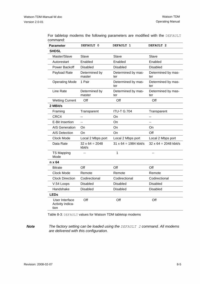
Watson-TDM-Manual-W.doc
Version 2.0-01
Watson TDM Operating Manual
Revision: 2008-02-07 8-5
For tabletop modems the following parameters are modified with the DEFAULT command: Parameter DEFAULT 0 DEFAULT 1 DEFAULT 2
SHDSL Master/Slave Slave Slave Slave Autorestart Enabled Enabled Enabled Power Backoff Disabled Disabled Disabled Payload Rate Determined by
master Determined by mas-ter
Determined by mas-ter
Operating Mode 1 Pair Determined by mas-ter
Determined by mas-ter
Line Rate Determined by master
Determined by mas-ter
Determined by mas-ter
Wetting Current Off Off Off 2 MBit/s
Framing Transparent ITU-T G.704 Transparent CRC4 -- On -- E-Bit Insertion -- On -- AIS Generation On On On AIS Detection On On Off Clock Mode Local 2 Mbps port Local 2 Mbps port Local 2 Mbps port Data Rate 32 x 64 = 2048
kbit/s 31 x 64 = 1984 kbit/s 32 x 64 = 2048 kbit/s
TS Mapping Mode
-- 1 --
n x 64 Bitrate Off Off Off Clock Mode Remote Remote Remote Clock Direction Codirectional Codirectional Codirectional V.54 Loops Disabled Disabled Disabled Handshake Disabled Disabled Disabled
LEDs User Interface Activity indica-tion
Off Off Off
Table 8-3: DEFAULT values for Watson TDM tabletop modems
Note The factory setting can be loaded using the DEFAULT 2 command. All modems
are delivered with this configuration.
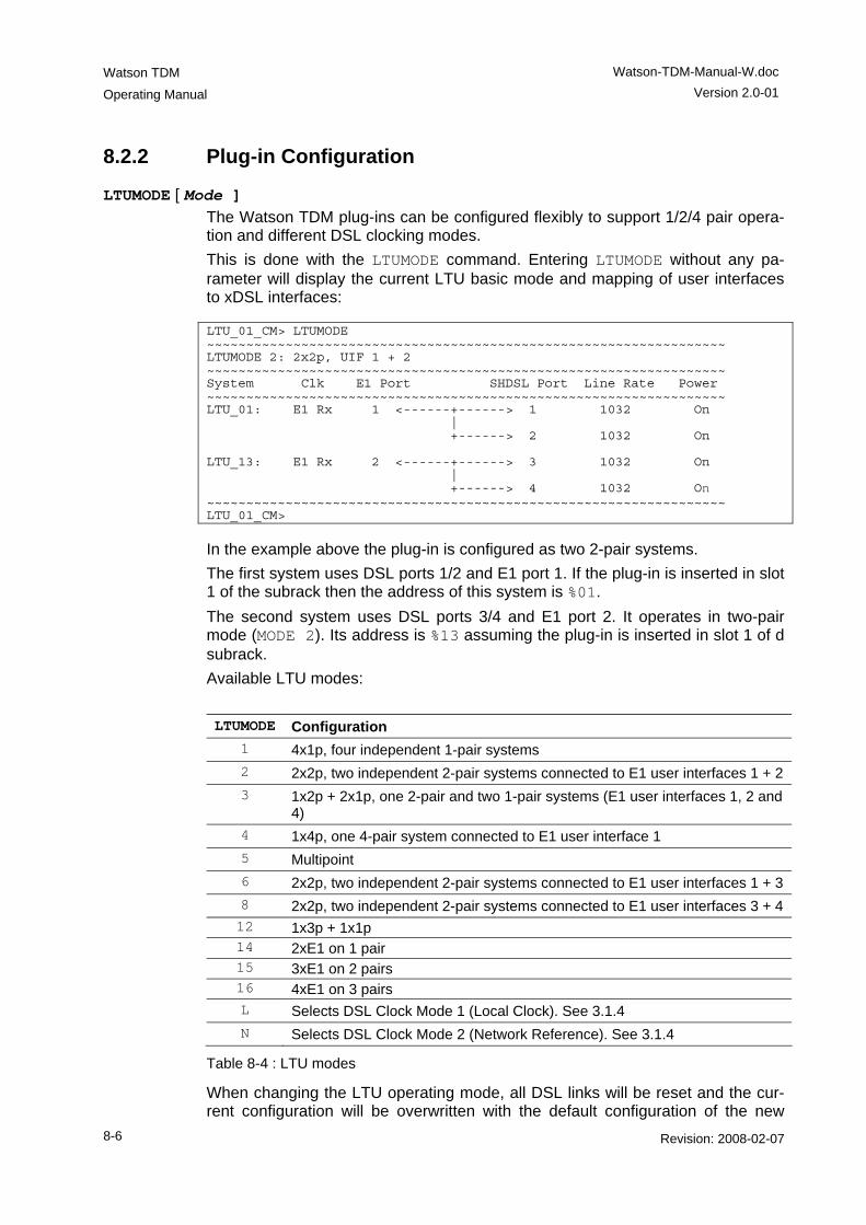
Watson TDM
Operating Manual
Watson-TDM-Manual-W.doc Version 2.0-01
8-6 Revision: 2008-02-07
8.2.2 Plug-in Configuration
LTUMODE [ Mode ] The Watson TDM plug-ins can be configured flexibly to support 1/2/4 pair opera-tion and different DSL clocking modes. This is done with the LTUMODE command. Entering LTUMODE without any pa-rameter will display the current LTU basic mode and mapping of user interfaces to xDSL interfaces: LTU_01_CM> LTUMODE ~~~~~~~~~~~~~~~~~~~~~~~~~~~~~~~~~~~~~~~~~~~~~~~~~~~~~~~~~~~~~~~~~~ LTUMODE 2: 2x2p, UIF 1 + 2 ~~~~~~~~~~~~~~~~~~~~~~~~~~~~~~~~~~~~~~~~~~~~~~~~~~~~~~~~~~~~~~~~~~ System Clk E1 Port SHDSL Port Line Rate Power ~~~~~~~~~~~~~~~~~~~~~~~~~~~~~~~~~~~~~~~~~~~~~~~~~~~~~~~~~~~~~~~~~~ LTU_01: E1 Rx 1 <------+------> 1 1032 On | +------> 2 1032 On LTU_13: E1 Rx 2 <------+------> 3 1032 On | +------> 4 1032 On ~~~~~~~~~~~~~~~~~~~~~~~~~~~~~~~~~~~~~~~~~~~~~~~~~~~~~~~~~~~~~~~~~~ LTU_01_CM>
In the example above the plug-in is configured as two 2-pair systems. The first system uses DSL ports 1/2 and E1 port 1. If the plug-in is inserted in slot 1 of the subrack then the address of this system is %01. The second system uses DSL ports 3/4 and E1 port 2. It operates in two-pair mode (MODE 2). Its address is %13 assuming the plug-in is inserted in slot 1 of d subrack. Available LTU modes: LTUMODE Configuration
1 4x1p, four independent 1-pair systems 2 2x2p, two independent 2-pair systems connected to E1 user interfaces 1 + 2 3 1x2p + 2x1p, one 2-pair and two 1-pair systems (E1 user interfaces 1, 2 and
4) 4 1x4p, one 4-pair system connected to E1 user interface 1 5 Multipoint 6 2x2p, two independent 2-pair systems connected to E1 user interfaces 1 + 3 8 2x2p, two independent 2-pair systems connected to E1 user interfaces 3 + 4 12 1x3p + 1x1p 14 2xE1 on 1 pair 15 3xE1 on 2 pairs 16 4xE1 on 3 pairs L Selects DSL Clock Mode 1 (Local Clock). See 3.1.4 N Selects DSL Clock Mode 2 (Network Reference). See 3.1.4
Table 8-4 : LTU modes
When changing the LTU operating mode, all DSL links will be reset and the cur-rent configuration will be overwritten with the default configuration of the new
Watson-TDM-Manual-W.doc
Version 2.0-01
Watson TDM Operating Manual
Revision: 2008-02-07 8-7
mode as per Table 8-2. Note that only the DSL defaults as per Table 8-2 are set, the E1 interface configuration is not changed by LTUMODE. For security reasons, the command must be confirmed. The LTUMODE can only be changed within the configuration menu of the first sub-system of a plug-in. LTUMODE without parameters will display the current LTU mode
Note Depending on the hardware configuration of a plug-in not all possible LTUMODEs are supported.
8.2.3 DSL Configuration BACKOFF ON | OFF
Set SHDSL Power Back-Off function ON / OFF.
LINERATE n [z] [p] [a] Set line rate: n the number of DSL timeslots to be transmitted (3 ≤ n ≤ 89) z use of one Z-bit: Setting z to 0 or omitting z means that the DSL EOC runs
at 3.2 kbit/s. Setting z to 1 increases the EOC bandwidth to 11.2 kbit/s. p the number of constellations: use 16 for p to configure 16 constellations
(TC-PAM 16) and 32 for 32 constellations (TC-PAM 32). If possible (i.e. consistent with n) the DSL link will be configured with this desired constella-tion. If p is omitted, TC-PAM 16 will be configured when possible and TC-PAM 32 otherwise.
a 1 denotes asymmetric PSD operation Notes • Asymmetric PSD is only possible without Z-bits, i.e. a = 1 implies z = 0
• The additional Z-bit is not supported by the Watson TDM Regenerator. Links with regenerators should be configured without specifying z. Other values for z are ignored on regenerated links.
• Watson 5 does not support TC-PAM 32. A DSL link between Watson TDM (as DSL master) and Watson 5 (as DSL slave) will not start if the DSL master is configured for TC-PAM 32.
MASTER ON | OFF Set DSL master mode ON / OFF (MASTER OFF configures the modem as DSL slave). On a plug-in with several subsystems each DSL link can individually be config-ured as DSL master or DSL slave
Watson TDM
Operating Manual
Watson-TDM-Manual-W.doc Version 2.0-01
8-8 Revision: 2008-02-07
MODE number-of-pairs MODE 1: 1 pair operation MODE 2: 2 pair operation MODE 3: 3 pair operation MODE 4: 4 pair operation See 3.1.3.
Note MODE causes a restart of the DSL link
POWER ON | OFF Set DSL remote powering ON / OFF.
RESTART ON | OFF Set DSL autorestart ON / OFF.
WETTING ON | OFF Enables (ON) or disables (OFF) sinking of wetting current. Only available on table-top modems.
8.2.4 User Interface Configuration ACTLED ON | OFF
Turns user interface activity on (ACTLED ON) or off (ACTLED OFF). If turned on then activity on the user interface will be shown on the LED "2" (LED "Remote") on the tabletop modem. The Activity LED blinks if at least one signal transition has been detected within one second on Tx or Rx. If activity is detected on Tx (user data towards DSL) then the LED is blinking green. If activity is detected on Rx (user data from DSL) the LED will blink amber. If activity is detected on both Tx Data and Rx Data, the LED will blink alternating green/amber. User interface activity indication is available on modems with a nx64 user inter-face and on modems with an E1 user interface and if the interface is operated in G.703 transparent/unframed mode. In case of multiservice operation, only activity of the nx64 user interface is indicated, while activity on the E1 interface is not monitored. Invoking a DEFAULT command will disable user interface activity indication.
Note: User interface activity indication is only available if the unit is configured as Slave.
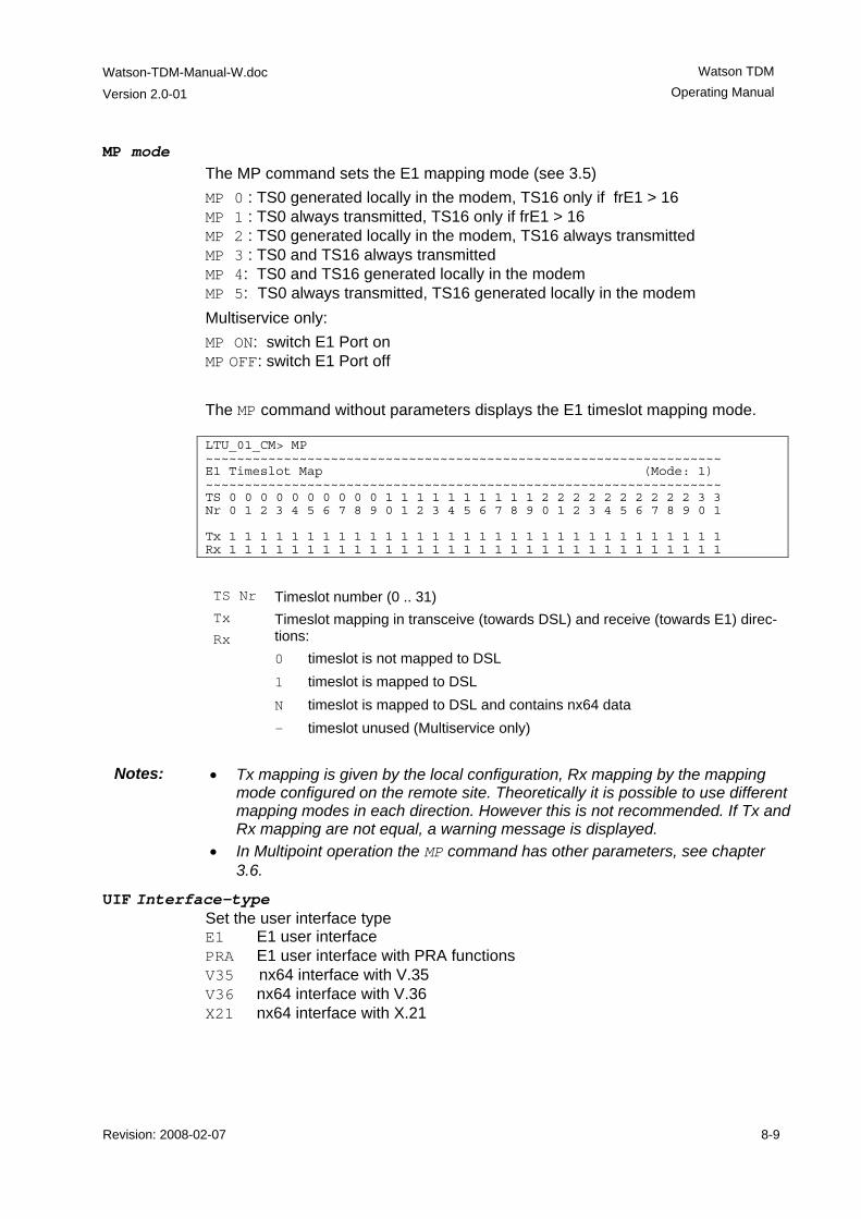
Watson-TDM-Manual-W.doc
Version 2.0-01
Watson TDM Operating Manual
Revision: 2008-02-07 8-9
MP mode The MP command sets the E1 mapping mode (see 3.5) MP 0 : TS0 generated locally in the modem, TS16 only if frE1 > 16 MP 1 : TS0 always transmitted, TS16 only if frE1 > 16 MP 2 : TS0 generated locally in the modem, TS16 always transmitted MP 3 : TS0 and TS16 always transmitted MP 4: TS0 and TS16 generated locally in the modem MP 5: TS0 always transmitted, TS16 generated locally in the modem Multiservice only: MP ON: switch E1 Port on MP OFF: switch E1 Port off The MP command without parameters displays the E1 timeslot mapping mode. LTU_01_CM> MP ~~~~~~~~~~~~~~~~~~~~~~~~~~~~~~~~~~~~~~~~~~~~~~~~~~~~~~~~~~~~~~~~~~ E1 Timeslot Map (Mode: 1) ~~~~~~~~~~~~~~~~~~~~~~~~~~~~~~~~~~~~~~~~~~~~~~~~~~~~~~~~~~~~~~~~~~ TS 0 0 0 0 0 0 0 0 0 0 1 1 1 1 1 1 1 1 1 1 2 2 2 2 2 2 2 2 2 2 3 3 Nr 0 1 2 3 4 5 6 7 8 9 0 1 2 3 4 5 6 7 8 9 0 1 2 3 4 5 6 7 8 9 0 1 Tx 1 1 1 1 1 1 1 1 1 1 1 1 1 1 1 1 1 1 1 1 1 1 1 1 1 1 1 1 1 1 1 1 Rx 1 1 1 1 1 1 1 1 1 1 1 1 1 1 1 1 1 1 1 1 1 1 1 1 1 1 1 1 1 1 1 1 TS Nr Timeslot number (0 .. 31) Tx
Rx Timeslot mapping in transceive (towards DSL) and receive (towards E1) direc-tions: 0 timeslot is not mapped to DSL 1 timeslot is mapped to DSL N timeslot is mapped to DSL and contains nx64 data - timeslot unused (Multiservice only)
Notes: • Tx mapping is given by the local configuration, Rx mapping by the mapping
mode configured on the remote site. Theoretically it is possible to use different mapping modes in each direction. However this is not recommended. If Tx and Rx mapping are not equal, a warning message is displayed.
• In Multipoint operation the MP command has other parameters, see chapter 3.6.
UIF Interface-type Set the user interface type E1 E1 user interface PRA E1 user interface with PRA functions V35 nx64 interface with V.35 V36 nx64 interface with V.36 X21 nx64 interface with X.21
Watson TDM
Operating Manual
Watson-TDM-Manual-W.doc Version 2.0-01
8-10 Revision: 2008-02-07
8.2.5 E1 Configuration AISDET ON | OFF
Set AIS detection (see 3.2.2): ON Reception of AIS on the E1 user interface generates an AIS alarm OFF AIS on the E1 user interface is ignored
AISGEN ON | OFF | T Set AIS generation (see 3.2.3): ON AIS is generated on the E1 user interface if AIS is detected on the remote
user interface or if the DSL link looses synchronization OFF AIS is never generated on the E1 user interface. The E1 user interface is
switched off if AIS is detected on the remote user interface or if the DSL link looses synchronization
T Transparent: if AIS is signaled from the remote E1 interface (reception of AIS-R) then AIS is sent on the local interface. The E1 interface is switched off if the DSL link looses synchronization.
CLK2M Clockmode Select source of 2 MBit/s clock: EXT external clock source INT internal clock source E1 clock from E1 port
Note: The CLK2M command can only be applied to the first DSL system and the command must be confirmed by entering it twice. It will then affect all other sys-tems configured with LTUMODE on the plug-in, see 8.2.2.
CRC4 ON | OFF Set CRC4 mode on / off.
EBIT ON | OFF Set automatic E-Bit insertion on / off.
G704 ON | OFF Set framed mode / transparent mode.
8.2.6 PRA Configuration
CRC4 option Set CRC4 processing option (Subscriber access option): CRC4 1 digital link without CRC4 processing CRC4 2 digital link with CRC4 processing CRC4 4 digital link with CRC4 monitoring This configuration only selects the subscriber access option of the whole digital section (NT1 and LT) if PRA Mode NT1 & LT is selected. If NT1 and LT functions run on different modems, the CRC4 settings of both modems determine the ac-cess option (see 3.2).
CRC4SA6 ON | OFF Set generation of CRC4 error notifications to the ET on / off (applies only to NT1).
Watson-TDM-Manual-W.doc
Version 2.0-01
Watson TDM Operating Manual
Revision: 2008-02-07 8-11
PRA option Select the ISDN PRA functional entities of the modem: PRA OFF no PRA function (transparent transmission) PRA NT1LT both NT1 and LT PRA LT only LT PRA NT1 only NT1
8.2.7 n x 64 kbit/s configuration
BITRATE rate Set bitrate of the nx64 Port : n = 1 .. 156 (64 Kbps .. 9'984 Kbps) To switch off the nx64 Port, set bitrate to 0.
Warning: If a multiservice tabletop modem is remotely powered be sure not to enable the nx64 kbit/s interface (by setting BITRATE to a value > 0) if the modem is operat-ing at the remote power limit with just the E1 interface enabled. Due to the higher power consumption of the nx64 kbit/s interface the current limiter at the plug-in might operate, thus switching off remote power feeding. Subsequent startups will not be successful. The system will not operate until the tabletop modem is reconfigured locally.
BYTETIMING ON | OFF
Select whether or not circuit B for byte timing is used in X.21 mode. Note that to use byte timing you need the appropriate cable and cannot use the co-directional transmit clock. This command is only available in X.21 mode.
CLOCKDIR direction Select clock direction: 0 = codirectional, 1 = contradirectional. This command is only available in V.35 and V.36 modes.
CLOCKMODE source Select clock source: 0 = nx64 Port, 1 = E1 Port 2, 2 = Internal, 3 = Remote.
CLOCKPOL polarity The CLOCKPOL command selects the sampling instant for the incoming data stream on circuit T of the X.21 user interface. In normal configuration (CLOCKPOL 0) circuit T is sampled on the rising edge of clock S. The data transi-tions on T and R occur at the OFF to ON transition of S (according X.24). The ON to OFF transition of circuit S nominally indicates the center of each signal ele-ment, in this case on circuit R. When Clock Polarity is set to inverted (CLOCKPOL 1), circuit T is sampled with the falling slope of S and the incoming data at X.21 circuit T is sampled at the OFF to ON transition of S. This command is only available in X.21 mode.
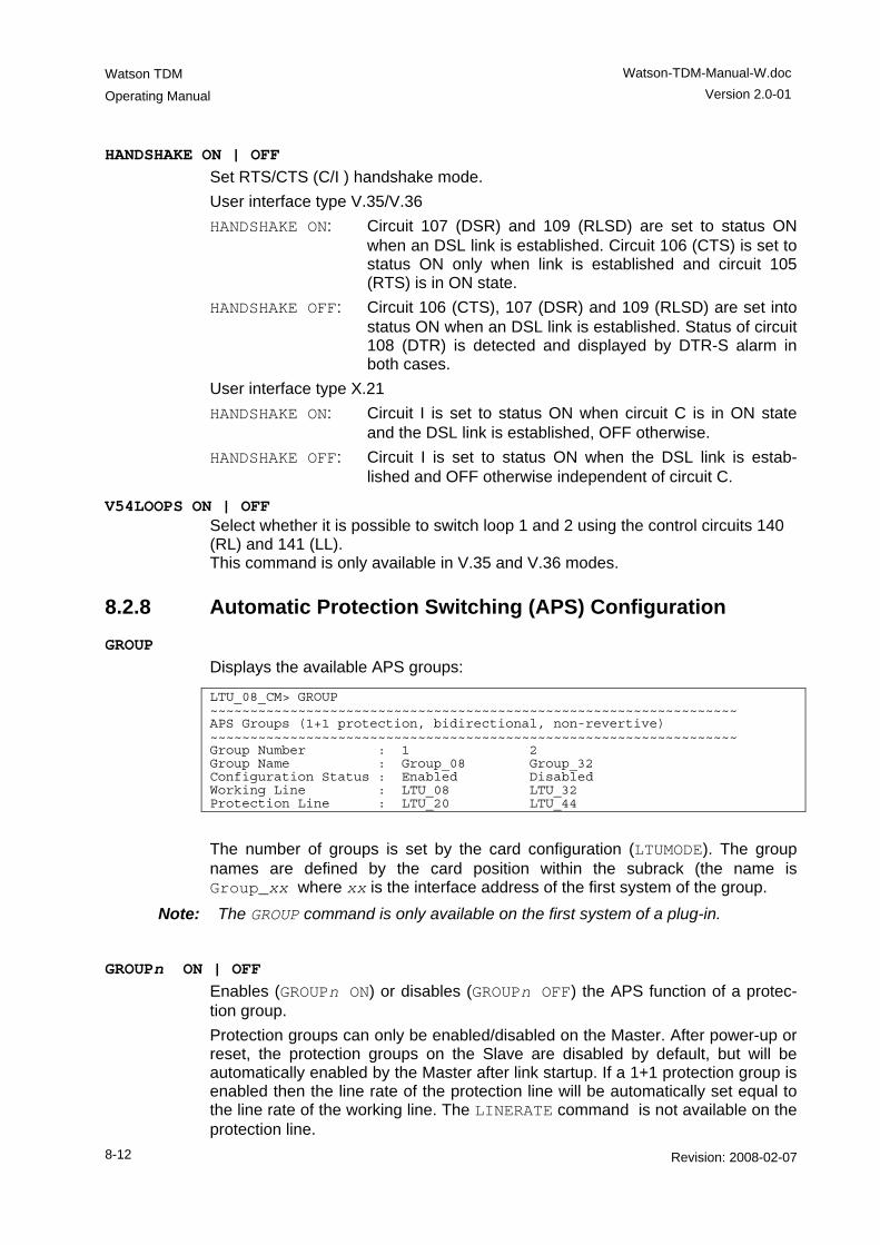
Watson TDM
Operating Manual
Watson-TDM-Manual-W.doc Version 2.0-01
8-12 Revision: 2008-02-07
HANDSHAKE ON | OFF Set RTS/CTS (C/I ) handshake mode. User interface type V.35/V.36 HANDSHAKE ON: Circuit 107 (DSR) and 109 (RLSD) are set to status ON
when an DSL link is established. Circuit 106 (CTS) is set to status ON only when link is established and circuit 105 (RTS) is in ON state.
HANDSHAKE OFF: Circuit 106 (CTS), 107 (DSR) and 109 (RLSD) are set into status ON when an DSL link is established. Status of circuit 108 (DTR) is detected and displayed by DTR-S alarm in both cases.
User interface type X.21 HANDSHAKE ON: Circuit I is set to status ON when circuit C is in ON state
and the DSL link is established, OFF otherwise. HANDSHAKE OFF: Circuit I is set to status ON when the DSL link is estab-
lished and OFF otherwise independent of circuit C.
V54LOOPS ON | OFF Select whether it is possible to switch loop 1 and 2 using the control circuits 140 (RL) and 141 (LL). This command is only available in V.35 and V.36 modes.
8.2.8 Automatic Protection Switching (APS) Configuration GROUP
Displays the available APS groups:
LTU_08_CM> GROUP ~~~~~~~~~~~~~~~~~~~~~~~~~~~~~~~~~~~~~~~~~~~~~~~~~~~~~~~~~~~~~~~~~~ APS Groups (1+1 protection, bidirectional, non-revertive) ~~~~~~~~~~~~~~~~~~~~~~~~~~~~~~~~~~~~~~~~~~~~~~~~~~~~~~~~~~~~~~~~~~ Group Number : 1 2 Group Name : Group_08 Group_32 Configuration Status : Enabled Disabled Working Line : LTU_08 LTU_32 Protection Line : LTU_20 LTU_44
The number of groups is set by the card configuration (LTUMODE). The group names are defined by the card position within the subrack (the name is Group_xx where xx is the interface address of the first system of the group.
Note: The GROUP command is only available on the first system of a plug-in.
GROUPn ON | OFF Enables (GROUPn ON) or disables (GROUPn OFF) the APS function of a protec-tion group. Protection groups can only be enabled/disabled on the Master. After power-up or reset, the protection groups on the Slave are disabled by default, but will be automatically enabled by the Master after link startup. If a 1+1 protection group is enabled then the line rate of the protection line will be automatically set equal to the line rate of the working line. The LINERATE command is not available on the protection line.
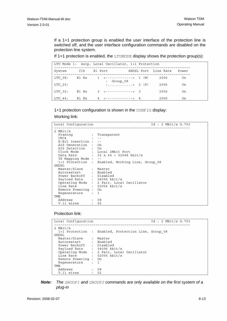
Watson-TDM-Manual-W.doc
Version 2.0-01
Watson TDM Operating Manual
Revision: 2008-02-07 8-13
If a 1+1 protection group is enabled the user interface of the protection line is switched off, and the user interface configuration commands are disabled on the protection line system. If 1+1 protection is enabled, the LTUMODE display shows the protection group(s):
LTU Mode 1: 4x1p, Local Oscillator, 1+1 Protection ~~~~~~~~~~~~~~~~~~~~~~~~~~~~~~~~~~~~~~~~~~~~~~~~~~~~~~~~~~~~~~~~~~ System Clk E1 Port SHDSL Port Line Rate Power ~~~~~~~~~~~~~~~~~~~~~~~~~~~~~~~~~~~~~~~~~~~~~~~~~~~~~~~~~~~~~~~~~~ LTU_08: E1 Rx 1 <-------------> 1 (W) 2056 On : Group_08 LTU_20: :............> 2 (P) 2056 On LTU_32: E1 Rx 3 <-------------> 3 2056 On LTU_44: E1 Rx 4 <-------------> 4 2056 On
1+1 protection configuration is shown in the CONFIG display: Working link:
Local Configuration Id : 2 MBit/s G.703 ~~~~~~~~~~~~~~~~~~~~~~~~~~~~~~~~~~~~~~~~~~~~~~~~~~~~~~~~~~~~~~~~~~ 2 MBit/s Framing : Transparent CRC4 : -- E-Bit Insertion : -- AIS Generation : On AIS Detection : On Clock Mode : Local 2Mbit Port Data Rate : 32 x 64 = 02048 kbit/s TS Mapping Mode : -- 1+1 Protection : Enabled, Working Line, Group_08 SHDSL Master/Slave : Master Autorestart : Enabled Power Backoff : Disabled Payload Rate : 04096 kbit/s Operating Mode : 2 Pair, Local Oscillator Line Rate : 02056 kbit/s Remote Powering : On Regenerators : 1 TMN Address : 08 V.11 wires : 02
Protection link:
Local Configuration Id : 2 MBit/s G.703 ~~~~~~~~~~~~~~~~~~~~~~~~~~~~~~~~~~~~~~~~~~~~~~~~~~~~~~~~~~~~~~~~~~ 2 MBit/s 1+1 Protection : Enabled, Protection Line, Group_08 SHDSL Master/Slave : Master Autorestart : Enabled Power Backoff : Disabled Payload Rate : 04096 kbit/s Operating Mode : 2 Pair, Local Oscillator Line Rate : 02056 kbit/s Remote Powering : On Regenerators : 1 TMN Address : 08 V.11 wires : 02
Note: The GROUP1 and GROUP2 commands are only available on the first system of a plug-in
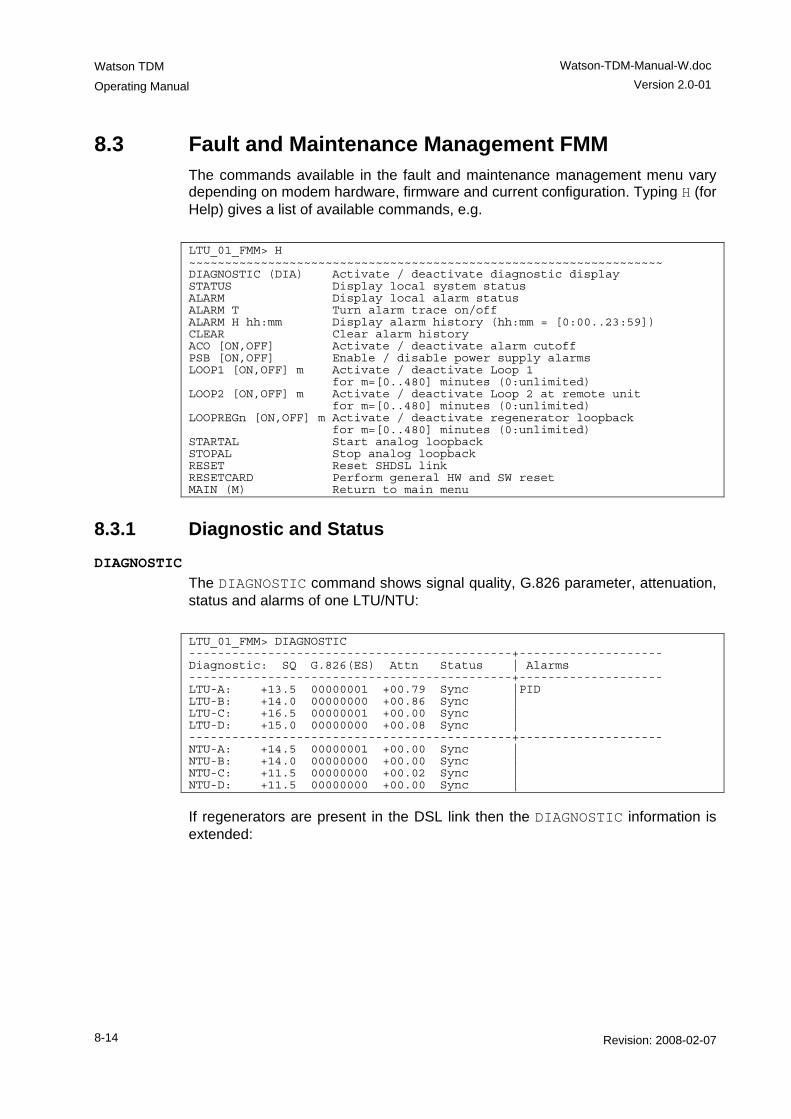
Watson TDM
Operating Manual
Watson-TDM-Manual-W.doc Version 2.0-01
8-14 Revision: 2008-02-07
8.3 Fault and Maintenance Management FMM The commands available in the fault and maintenance management menu vary depending on modem hardware, firmware and current configuration. Typing H (for Help) gives a list of available commands, e.g. LTU_01_FMM> H ~~~~~~~~~~~~~~~~~~~~~~~~~~~~~~~~~~~~~~~~~~~~~~~~~~~~~~~~~~~~~~~~~~ DIAGNOSTIC (DIA) Activate / deactivate diagnostic display STATUS Display local system status ALARM Display local alarm status ALARM T Turn alarm trace on/off ALARM H hh:mm Display alarm history (hh:mm = [0:00..23:59]) CLEAR Clear alarm history ACO [ON,OFF] Activate / deactivate alarm cutoff PSB [ON,OFF] Enable / disable power supply alarms LOOP1 [ON,OFF] m Activate / deactivate Loop 1 for m=[0..480] minutes (0:unlimited) LOOP2 [ON,OFF] m Activate / deactivate Loop 2 at remote unit for m=[0..480] minutes (0:unlimited) LOOPREGn [ON,OFF] m Activate / deactivate regenerator loopback for m=[0..480] minutes (0:unlimited) STARTAL Start analog loopback STOPAL Stop analog loopback RESET Reset SHDSL link RESETCARD Perform general HW and SW reset MAIN (M) Return to main menu
8.3.1 Diagnostic and Status DIAGNOSTIC
The DIAGNOSTIC command shows signal quality, G.826 parameter, attenuation, status and alarms of one LTU/NTU: LTU_01_FMM> DIAGNOSTIC ---------------------------------------------+-------------------- Diagnostic: SQ G.826(ES) Attn Status | Alarms ---------------------------------------------+-------------------- LTU-A: +13.5 00000001 +00.79 Sync |PID LTU-B: +14.0 00000000 +00.86 Sync | LTU-C: +16.5 00000001 +00.00 Sync | LTU-D: +15.0 00000000 +00.08 Sync | ---------------------------------------------+-------------------- NTU-A: +14.5 00000001 +00.00 Sync | NTU-B: +14.0 00000000 +00.00 Sync | NTU-C: +11.5 00000000 +00.02 Sync | NTU-D: +11.5 00000000 +00.00 Sync |
If regenerators are present in the DSL link then the DIAGNOSTIC information is extended:
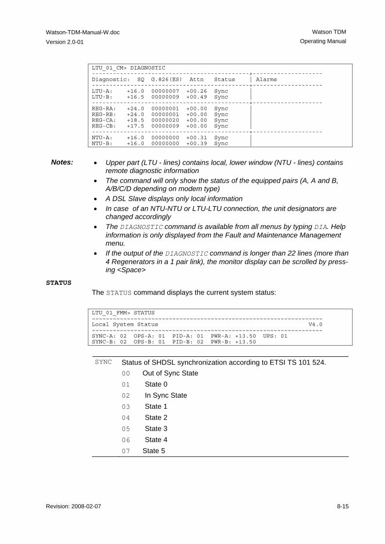
Watson-TDM-Manual-W.doc
Version 2.0-01
Watson TDM Operating Manual
Revision: 2008-02-07 8-15
LTU_01_CM> DIAGNOSTIC ---------------------------------------------+-------------------- Diagnostic: SQ G.826(ES) Attn Status | Alarms ---------------------------------------------+-------------------- LTU-A: +16.0 00000007 +00.26 Sync | LTU-B: +16.5 00000009 +00.49 Sync | ---------------------------------------------+-------------------- REG-RA: +24.0 00000001 +00.00 Sync | REG-RB: +24.0 00000001 +00.00 Sync | REG-CA: +18.5 00000020 +00.00 Sync | REG-CB: +17.5 00000009 +00.00 Sync | ---------------------------------------------+-------------------- NTU-A: +16.0 00000000 +00.31 Sync | NTU-B: +16.0 00000000 +00.39 Sync |
Notes: • Upper part (LTU - lines) contains local, lower window (NTU - lines) contains
remote diagnostic information • The command will only show the status of the equipped pairs (A, A and B,
A/B/C/D depending on modem type) • A DSL Slave displays only local information • In case of an NTU-NTU or LTU-LTU connection, the unit designators are
changed accordingly • The DIAGNOSTIC command is available from all menus by typing DIA. Help
information is only displayed from the Fault and Maintenance Management menu.
• If the output of the DIAGNOSTIC command is longer than 22 lines (more than 4 Regenerators in a 1 pair link), the monitor display can be scrolled by press-ing <Space>
STATUS The STATUS command displays the current system status: LTU_01_FMM> STATUS ~~~~~~~~~~~~~~~~~~~~~~~~~~~~~~~~~~~~~~~~~~~~~~~~~~~~~~~~~~~~~~~~~~ Local System Status V4.0 ~~~~~~~~~~~~~~~~~~~~~~~~~~~~~~~~~~~~~~~~~~~~~~~~~~~~~~~~~~~~~~~~~~ SYNC-A: 02 OPS-A: 01 PID-A: 01 PWR-A: +13.50 UPS: 01 SYNC-B: 02 OPS-B: 01 PID-B: 02 PWR-B: +13.50
SYNC Status of SHDSL synchronization according to ETSI TS 101 524.
00 Out of Sync State 01 State 0 02 In Sync State 03 State 1 04 State 2 05 State 3 06 State 4 07 State 5
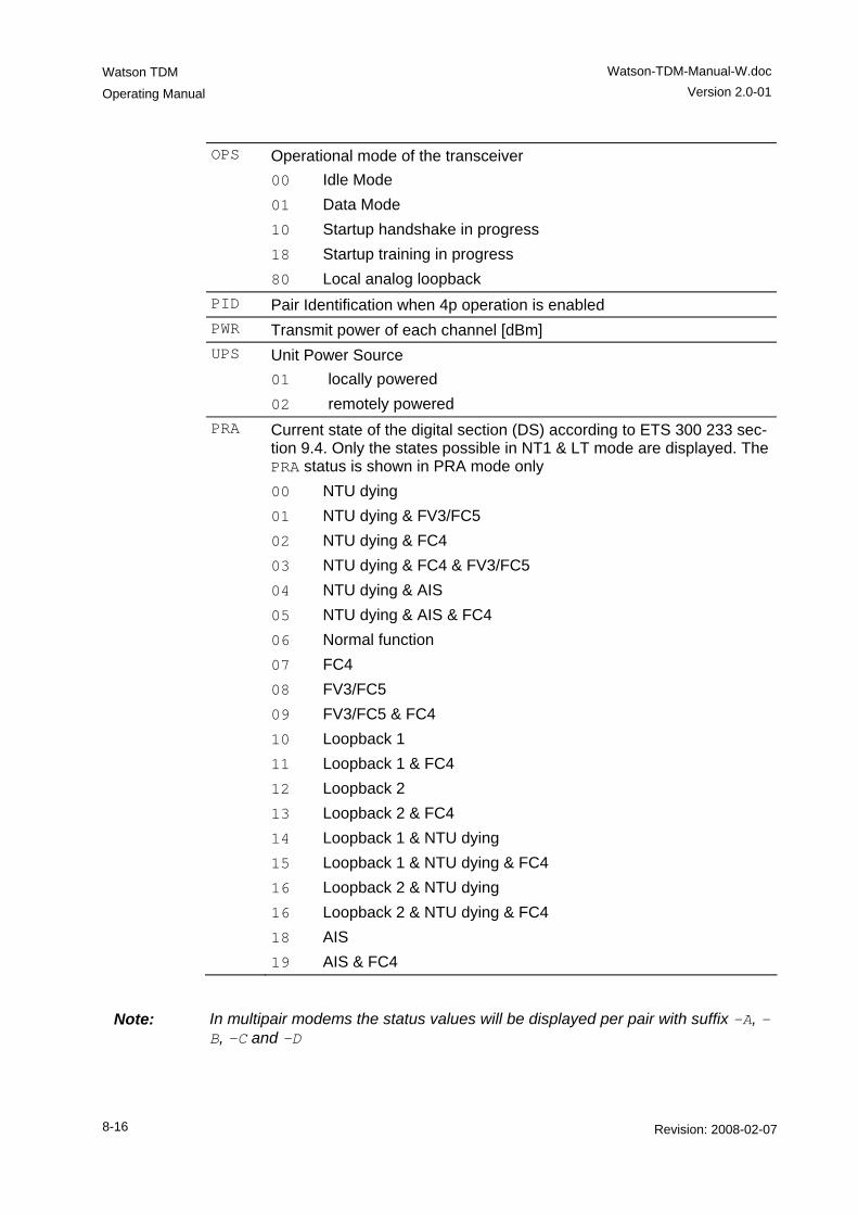
Watson TDM
Operating Manual
Watson-TDM-Manual-W.doc Version 2.0-01
8-16 Revision: 2008-02-07
OPS Operational mode of the transceiver 00 Idle Mode 01 Data Mode 10 Startup handshake in progress 18 Startup training in progress 80 Local analog loopback
PID Pair Identification when 4p operation is enabled PWR Transmit power of each channel [dBm] UPS Unit Power Source
01 locally powered 02 remotely powered
PRA Current state of the digital section (DS) according to ETS 300 233 sec-tion 9.4. Only the states possible in NT1 & LT mode are displayed. The PRA status is shown in PRA mode only 00 NTU dying 01 NTU dying & FV3/FC5 02 NTU dying & FC4 03 NTU dying & FC4 & FV3/FC5 04 NTU dying & AIS 05 NTU dying & AIS & FC4 06 Normal function 07 FC4 08 FV3/FC5 09 FV3/FC5 & FC4 10 Loopback 1 11 Loopback 1 & FC4 12 Loopback 2 13 Loopback 2 & FC4 14 Loopback 1 & NTU dying 15 Loopback 1 & NTU dying & FC4 16 Loopback 2 & NTU dying 16 Loopback 2 & NTU dying & FC4 18 AIS 19 AIS & FC4
Note: In multipair modems the status values will be displayed per pair with suffix –A, -B, -C and -D
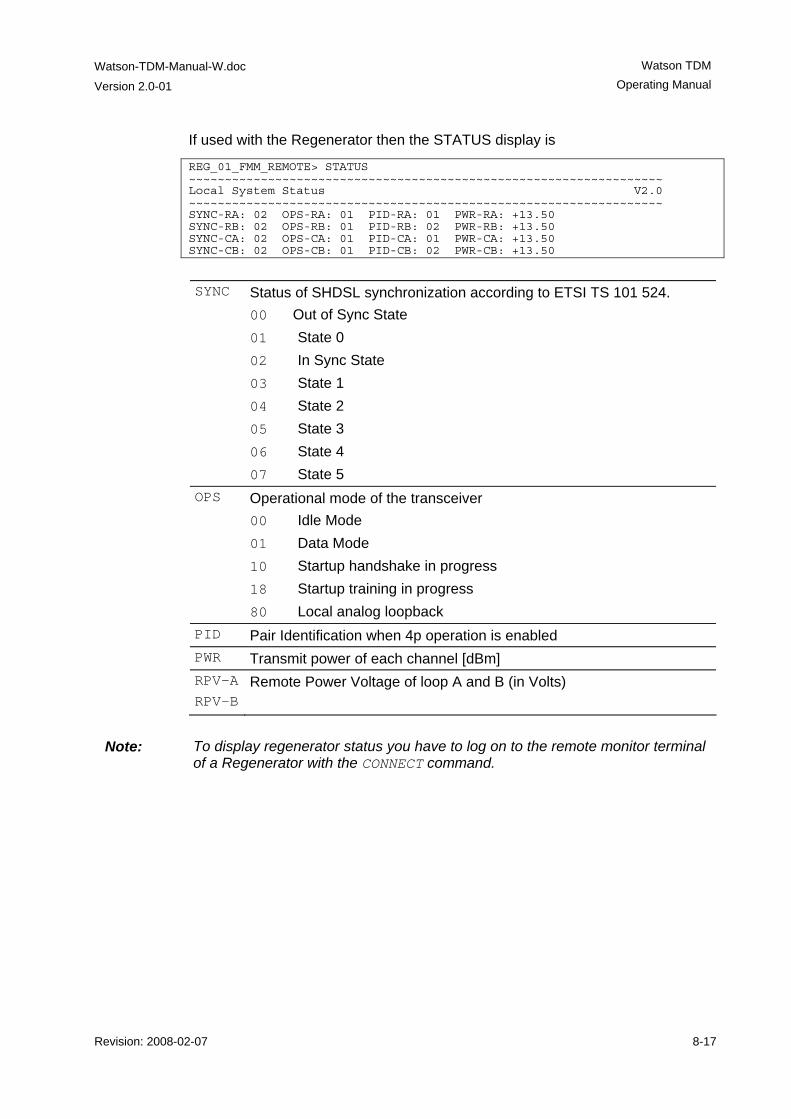
Watson-TDM-Manual-W.doc
Version 2.0-01
Watson TDM Operating Manual
Revision: 2008-02-07 8-17
If used with the Regenerator then the STATUS display is
REG_01_FMM_REMOTE> STATUS ~~~~~~~~~~~~~~~~~~~~~~~~~~~~~~~~~~~~~~~~~~~~~~~~~~~~~~~~~~~~~~~~~~ Local System Status V2.0 ~~~~~~~~~~~~~~~~~~~~~~~~~~~~~~~~~~~~~~~~~~~~~~~~~~~~~~~~~~~~~~~~~~ SYNC-RA: 02 OPS-RA: 01 PID-RA: 01 PWR-RA: +13.50 SYNC-RB: 02 OPS-RB: 01 PID-RB: 02 PWR-RB: +13.50 SYNC-CA: 02 OPS-CA: 01 PID-CA: 01 PWR-CA: +13.50 SYNC-CB: 02 OPS-CB: 01 PID-CB: 02 PWR-CB: +13.50
SYNC Status of SHDSL synchronization according to ETSI TS 101 524.
00 Out of Sync State 01 State 0 02 In Sync State 03 State 1 04 State 2 05 State 3 06 State 4 07 State 5
OPS Operational mode of the transceiver 00 Idle Mode 01 Data Mode 10 Startup handshake in progress 18 Startup training in progress 80 Local analog loopback
PID Pair Identification when 4p operation is enabled PWR Transmit power of each channel [dBm] RPV-ARPV-B
Remote Power Voltage of loop A and B (in Volts)
Note: To display regenerator status you have to log on to the remote monitor terminal
of a Regenerator with the CONNECT command.
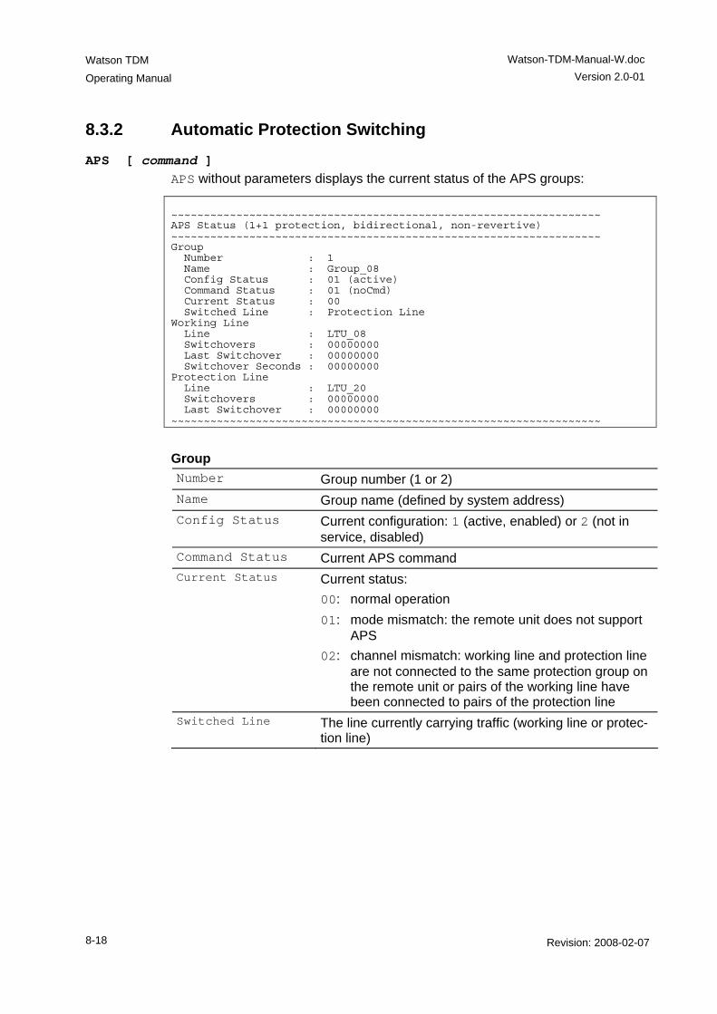
Watson TDM
Operating Manual
Watson-TDM-Manual-W.doc Version 2.0-01
8-18 Revision: 2008-02-07
8.3.2 Automatic Protection Switching
APS [ command ] APS without parameters displays the current status of the APS groups:
~~~~~~~~~~~~~~~~~~~~~~~~~~~~~~~~~~~~~~~~~~~~~~~~~~~~~~~~~~~~~~~~~~ APS Status (1+1 protection, bidirectional, non-revertive) ~~~~~~~~~~~~~~~~~~~~~~~~~~~~~~~~~~~~~~~~~~~~~~~~~~~~~~~~~~~~~~~~~~ Group Number : 1 Name : Group_08 Config Status : 01 (active) Command Status : 01 (noCmd) Current Status : 00 Switched Line : Protection Line Working Line Line : LTU_08 Switchovers : 00000000 Last Switchover : 00000000 Switchover Seconds : 00000000 Protection Line Line : LTU_20 Switchovers : 00000000 Last Switchover : 00000000 ~~~~~~~~~~~~~~~~~~~~~~~~~~~~~~~~~~~~~~~~~~~~~~~~~~~~~~~~~~~~~~~~~~
Group Number Group number (1 or 2) Name Group name (defined by system address) Config Status Current configuration: 1 (active, enabled) or 2 (not in
service, disabled) Command Status Current APS command Current Status Current status:
00: normal operation 01: mode mismatch: the remote unit does not support
APS 02: channel mismatch: working line and protection line
are not connected to the same protection group on the remote unit or pairs of the working line have been connected to pairs of the protection line
Switched Line The line currently carrying traffic (working line or protec-tion line)
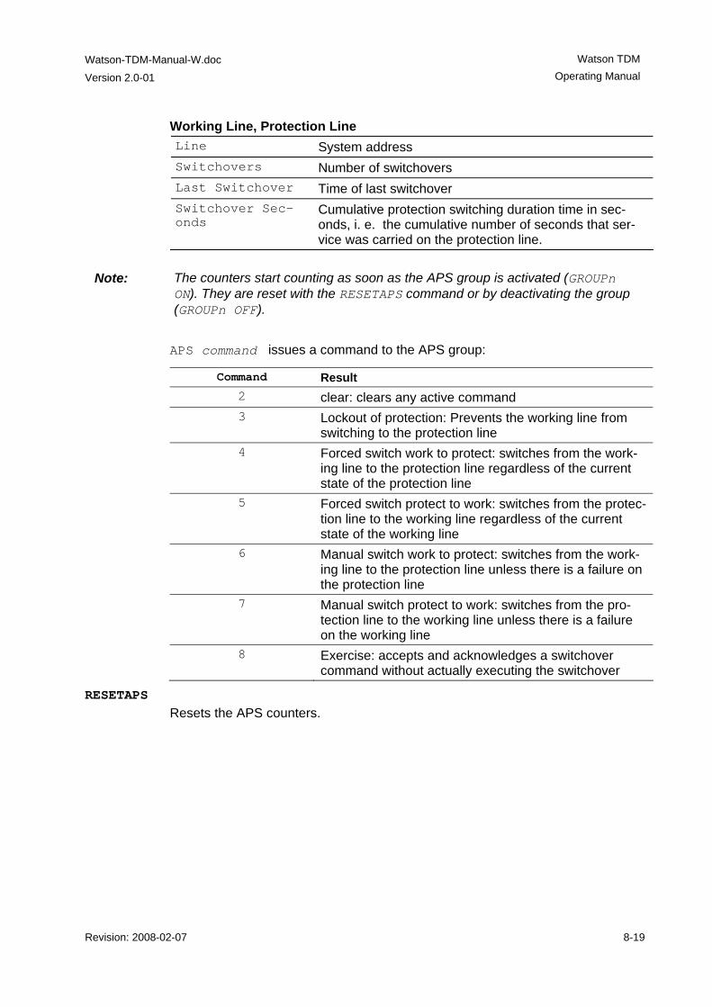
Watson-TDM-Manual-W.doc
Version 2.0-01
Watson TDM Operating Manual
Revision: 2008-02-07 8-19
Working Line, Protection Line Line System address Switchovers Number of switchovers Last Switchover Time of last switchover Switchover Sec-onds
Cumulative protection switching duration time in sec-onds, i. e. the cumulative number of seconds that ser-vice was carried on the protection line.
Note: The counters start counting as soon as the APS group is activated (GROUPn
ON). They are reset with the RESETAPS command or by deactivating the group (GROUPn OFF).
APS command issues a command to the APS group:
Command Result 2 clear: clears any active command 3 Lockout of protection: Prevents the working line from
switching to the protection line 4 Forced switch work to protect: switches from the work-
ing line to the protection line regardless of the current state of the protection line
5 Forced switch protect to work: switches from the protec-tion line to the working line regardless of the current state of the working line
6 Manual switch work to protect: switches from the work-ing line to the protection line unless there is a failure on the protection line
7 Manual switch protect to work: switches from the pro-tection line to the working line unless there is a failure on the working line
8 Exercise: accepts and acknowledges a switchover command without actually executing the switchover
RESETAPS Resets the APS counters.
Watson TDM
Operating Manual
Watson-TDM-Manual-W.doc Version 2.0-01
8-20 Revision: 2008-02-07
8.3.3 Alarm and Alarm History ACO ON | OFF
The ACO (Alarm Cut Off) command enables or disables the alarm relays. When ACO is 'on', all alarms are disabled and the alarm-relays are inactive. The local alarm LED signals a non-urgent alarm.
ALARM The ALARM command displays the current alarm status:
LTU_01_FMM> ALARM ~~~~~~~~~~~~~~~~~~~~~~~~~~~~~~~~~~~~~~~~~~~~~~~~~~~~~~~~~~~~~~~~~~ Local Alarm Status ~~~~~~~~~~~~~~~~~~~~~~~~~~~~~~~~~~~~~~~~~~~~~~~~~~~~~~~~~~~~~~~~~~ LOS-S:off AIS-S:off LOOP1:off ACO:off EXT-LOC:off LFA-S:off BER-S:off LOOP2:off ALB:off LOOPREG:off LOSW-A:off BER-A:off SEG-A:off CLD-A:off BERT:off
Alarms: ACO Alarm cutoff AIS-S AIS (Alarm Indication Signal) detected at subscriber (E1) side AIS-V3 Alarm indication signal at V3-reference point (PRA mode) ALB Analog loopback BER-x SHDSL block-error-rate according G.826 ≥ 30% on channel x (A,
B, C or D) BER-S Excessive Block Error Rate on subscriber side
If CRC4 enabled : BER-S = on if more than 805 CRC4 Errors per second. If CRC4 disabled : BER-S = on if more than 28 FAS Errors per second.
BERT BER test activated CLD-x Current limit detection on channel x (A, B, C or D) DTR-S Status of DTR (Data Terminal Ready) Handshake Signal in
V.35/V.36 mode: DTR Signal is detected as ‘ON’: DTR-S Alarm is off DTR Signal is detected as ‘OFF’: DTR-S Alarm is on In X.21 mode the DTR-S alarm depends on the state of Control-signal C. DTR-S alarm will always be off in X.21 mode if hand-shake is set to OFF.
EXT-LOC Loss of external clock LFA-S Loss of frame alignment at subscriber (E1) side LFA-V3 Loss of frame alignment at V3-reference point (PRA mode)
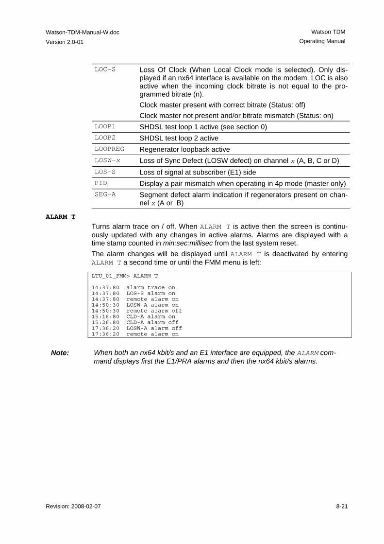
Watson-TDM-Manual-W.doc
Version 2.0-01
Watson TDM Operating Manual
Revision: 2008-02-07 8-21
LOC-S Loss Of Clock (When Local Clock mode is selected). Only dis-played if an nx64 interface is available on the modem. LOC is also active when the incoming clock bitrate is not equal to the pro-grammed bitrate (n). Clock master present with correct bitrate (Status: off) Clock master not present and/or bitrate mismatch (Status: on)
LOOP1 SHDSL test loop 1 active (see section 0) LOOP2 SHDSL test loop 2 active LOOPREG Regenerator loopback active LOSW-x Loss of Sync Defect (LOSW defect) on channel x (A, B, C or D) LOS-S Loss of signal at subscriber (E1) side PID Display a pair mismatch when operating in 4p mode (master only) SEG-A Segment defect alarm indication if regenerators present on chan-
nel x (A or B)
ALARM T Turns alarm trace on / off. When ALARM T is active then the screen is continu-ously updated with any changes in active alarms. Alarms are displayed with a time stamp counted in min:sec:millisec from the last system reset. The alarm changes will be displayed until ALARM T is deactivated by entering ALARM T a second time or until the FMM menu is left:
LTU_01_FMM> ALARM T 14:37:80 alarm trace on 14:37:80 LOS-S alarm on 14:37:80 remote alarm on 14:50:30 LOSW-A alarm on 14:50:30 remote alarm off 15:16:80 CLD-A alarm on 15:26:80 CLD-A alarm off 17:36:20 LOSW-A alarm off 17:36:20 remote alarm on
Note: When both an nx64 kbit/s and an E1 interface are equipped, the ALARM com-
mand displays first the E1/PRA alarms and then the nx64 kbit/s alarms.
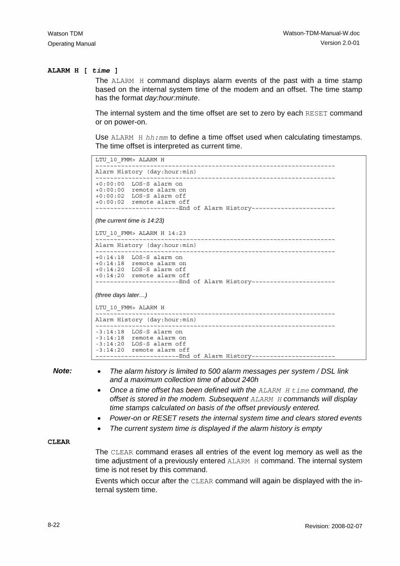
Watson TDM
Operating Manual
Watson-TDM-Manual-W.doc Version 2.0-01
8-22 Revision: 2008-02-07
ALARM H [ time ] The ALARM H command displays alarm events of the past with a time stamp based on the internal system time of the modem and an offset. The time stamp has the format day:hour:minute.
The internal system and the time offset are set to zero by each RESET command or on power-on.
Use ALARM H hh:mm to define a time offset used when calculating timestamps. The time offset is interpreted as current time.
LTU_10_FMM> ALARM H ~~~~~~~~~~~~~~~~~~~~~~~~~~~~~~~~~~~~~~~~~~~~~~~~~~~~~~~~~~~~~~~~~~ Alarm History (day:hour:min) ~~~~~~~~~~~~~~~~~~~~~~~~~~~~~~~~~~~~~~~~~~~~~~~~~~~~~~~~~~~~~~~~~~ +0:00:00 LOS-S alarm on +0:00:00 remote alarm on +0:00:02 LOS-S alarm off +0:00:02 remote alarm off ~~~~~~~~~~~~~~~~~~~~~~~End of Alarm History~~~~~~~~~~~~~~~~~~~~~~~ (the current time is 14:23) LTU_10_FMM> ALARM H 14:23 ~~~~~~~~~~~~~~~~~~~~~~~~~~~~~~~~~~~~~~~~~~~~~~~~~~~~~~~~~~~~~~~~~~ Alarm History (day:hour:min) ~~~~~~~~~~~~~~~~~~~~~~~~~~~~~~~~~~~~~~~~~~~~~~~~~~~~~~~~~~~~~~~~~~ +0:14:18 LOS-S alarm on +0:14:18 remote alarm on +0:14:20 LOS-S alarm off +0:14:20 remote alarm off ~~~~~~~~~~~~~~~~~~~~~~~End of Alarm History~~~~~~~~~~~~~~~~~~~~~~~ (three days later…) LTU_10_FMM> ALARM H ~~~~~~~~~~~~~~~~~~~~~~~~~~~~~~~~~~~~~~~~~~~~~~~~~~~~~~~~~~~~~~~~~~ Alarm History (day:hour:min) ~~~~~~~~~~~~~~~~~~~~~~~~~~~~~~~~~~~~~~~~~~~~~~~~~~~~~~~~~~~~~~~~~~ -3:14:18 LOS-S alarm on -3:14:18 remote alarm on -3:14:20 LOS-S alarm off -3:14:20 remote alarm off ~~~~~~~~~~~~~~~~~~~~~~~End of Alarm History~~~~~~~~~~~~~~~~~~~~~~~
Note: • The alarm history is limited to 500 alarm messages per system / DSL link and a maximum collection time of about 240h
• Once a time offset has been defined with the ALARM H time command, the offset is stored in the modem. Subsequent ALARM H commands will display time stamps calculated on basis of the offset previously entered.
• Power-on or RESET resets the internal system time and clears stored events • The current system time is displayed if the alarm history is empty
CLEAR The CLEAR command erases all entries of the event log memory as well as the time adjustment of a previously entered ALARM H command. The internal system time is not reset by this command. Events which occur after the CLEAR command will again be displayed with the in-ternal system time.
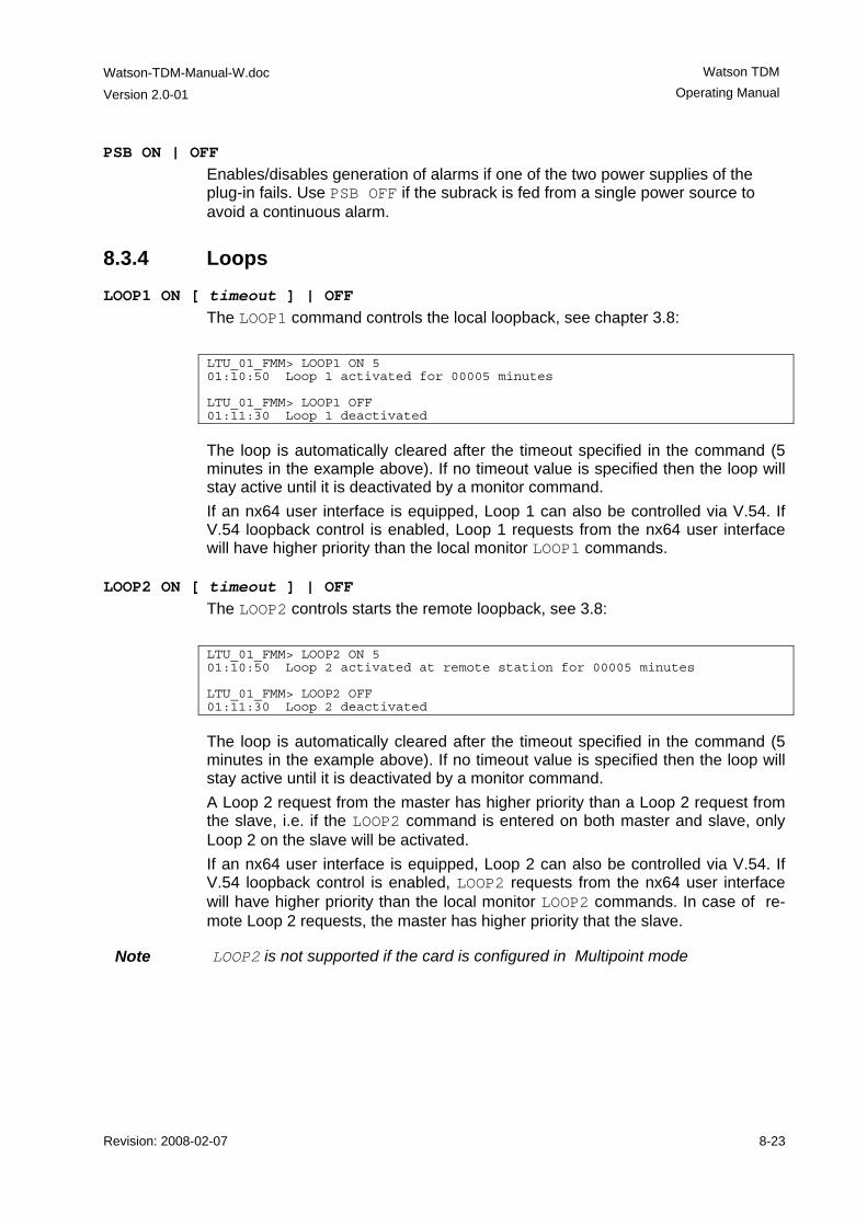
Watson-TDM-Manual-W.doc
Version 2.0-01
Watson TDM Operating Manual
Revision: 2008-02-07 8-23
PSB ON | OFF Enables/disables generation of alarms if one of the two power supplies of the plug-in fails. Use PSB OFF if the subrack is fed from a single power source to avoid a continuous alarm.
8.3.4 Loops
LOOP1 ON [ timeout ] | OFF The LOOP1 command controls the local loopback, see chapter 3.8: LTU_01_FMM> LOOP1 ON 5 01:10:50 Loop 1 activated for 00005 minutes LTU_01_FMM> LOOP1 OFF 01:11:30 Loop 1 deactivated
The loop is automatically cleared after the timeout specified in the command (5 minutes in the example above). If no timeout value is specified then the loop will stay active until it is deactivated by a monitor command. If an nx64 user interface is equipped, Loop 1 can also be controlled via V.54. If V.54 loopback control is enabled, Loop 1 requests from the nx64 user interface will have higher priority than the local monitor LOOP1 commands.
LOOP2 ON [ timeout ] | OFF The LOOP2 controls starts the remote loopback, see 3.8: LTU_01_FMM> LOOP2 ON 5 01:10:50 Loop 2 activated at remote station for 00005 minutes LTU_01_FMM> LOOP2 OFF 01:11:30 Loop 2 deactivated
The loop is automatically cleared after the timeout specified in the command (5 minutes in the example above). If no timeout value is specified then the loop will stay active until it is deactivated by a monitor command. A Loop 2 request from the master has higher priority than a Loop 2 request from the slave, i.e. if the LOOP2 command is entered on both master and slave, only Loop 2 on the slave will be activated. If an nx64 user interface is equipped, Loop 2 can also be controlled via V.54. If V.54 loopback control is enabled, LOOP2 requests from the nx64 user interface will have higher priority than the local monitor LOOP2 commands. In case of re-mote Loop 2 requests, the master has higher priority that the slave.
Note LOOP2 is not supported if the card is configured in Multipoint mode
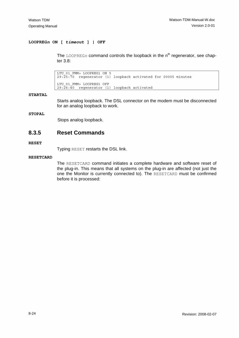
Watson TDM
Operating Manual
Watson-TDM-Manual-W.doc Version 2.0-01
8-24 Revision: 2008-02-07
LOOPREGn ON [ timeout ] | OFF
The LOOPREGn command controls the loopback in the nth regenerator, see chap-ter 3.8: LTU_01_FMM> LOOPREG1 ON 5 29:25:70 regenerator (1) loopback activated for 00005 minutes LTU_01_FMM> LOOPREG1 OFF 29:26:40 regenerator (1) loopback activated
STARTAL Starts analog loopback. The DSL connector on the modem must be disconnected for an analog loopback to work.
STOPAL Stops analog loopback.
8.3.5 Reset Commands RESET
Typing RESET restarts the DSL link.
RESETCARD The RESETCARD command initiates a complete hardware and software reset of the plug-in. This means that all systems on the plug-in are affected (not just the one the Monitor is currently connected to). The RESETCARD must be confirmed before it is processed:
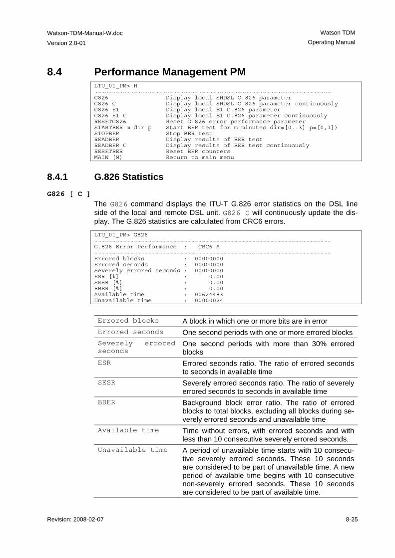
Watson-TDM-Manual-W.doc
Version 2.0-01
Watson TDM Operating Manual
Revision: 2008-02-07 8-25
8.4 Performance Management PM LTU_01_PM> H ~~~~~~~~~~~~~~~~~~~~~~~~~~~~~~~~~~~~~~~~~~~~~~~~~~~~~~~~~~~~~~~~~~ G826 Display local SHDSL G.826 parameter G826 C Display local SHDSL G.826 parameter continuously G826 E1 Display local E1 G.826 parameter G826 E1 C Display local E1 G.826 parameter continuously RESETG826 Reset G.826 error performance parameter STARTBER m dir p Start BER test for m minutes dir=[0..3] p=[0,1]) STOPBER Stop BER test READBER Display results of BER test READBER C Display results of BER test continuously RESETBER Reset BER counters MAIN (M) Return to main menu
8.4.1 G.826 Statistics G826 [ C ]
The G826 command displays the ITU-T G.826 error statistics on the DSL line side of the local and remote DSL unit. G826 C will continuously update the dis-play. The G.826 statistics are calculated from CRC6 errors.
LTU_01_PM> G826 ~~~~~~~~~~~~~~~~~~~~~~~~~~~~~~~~~~~~~~~~~~~~~~~~~~~~~~~~~~~~~~~~~~ G.826 Error Performance : CRC6 A ~~~~~~~~~~~~~~~~~~~~~~~~~~~~~~~~~~~~~~~~~~~~~~~~~~~~~~~~~~~~~~~~~~ Errored blocks : 00000000 Errored seconds : 00000000 Severely errored seconds : 00000000 ESR [%] : 0.00 SESR [%] : 0.00 BBER [%] : 0.00 Available time : 00624483 Unavailable time : 00000024
Errored blocks A block in which one or more bits are in error Errored seconds One second periods with one or more errored blocks Severely errored seconds
One second periods with more than 30% errored blocks
ESR Errored seconds ratio. The ratio of errored seconds to seconds in available time
SESR Severely errored seconds ratio. The ratio of severely errored seconds to seconds in available time
BBER Background block error ratio. The ratio of errored blocks to total blocks, excluding all blocks during se-verely errored seconds and unavailable time
Available time Time without errors, with errored seconds and with less than 10 consecutive severely errored seconds.
Unavailable time A period of unavailable time starts with 10 consecu-tive severely errored seconds. These 10 seconds are considered to be part of unavailable time. A new period of available time begins with 10 consecutive non-severely errored seconds. These 10 seconds are considered to be part of available time.
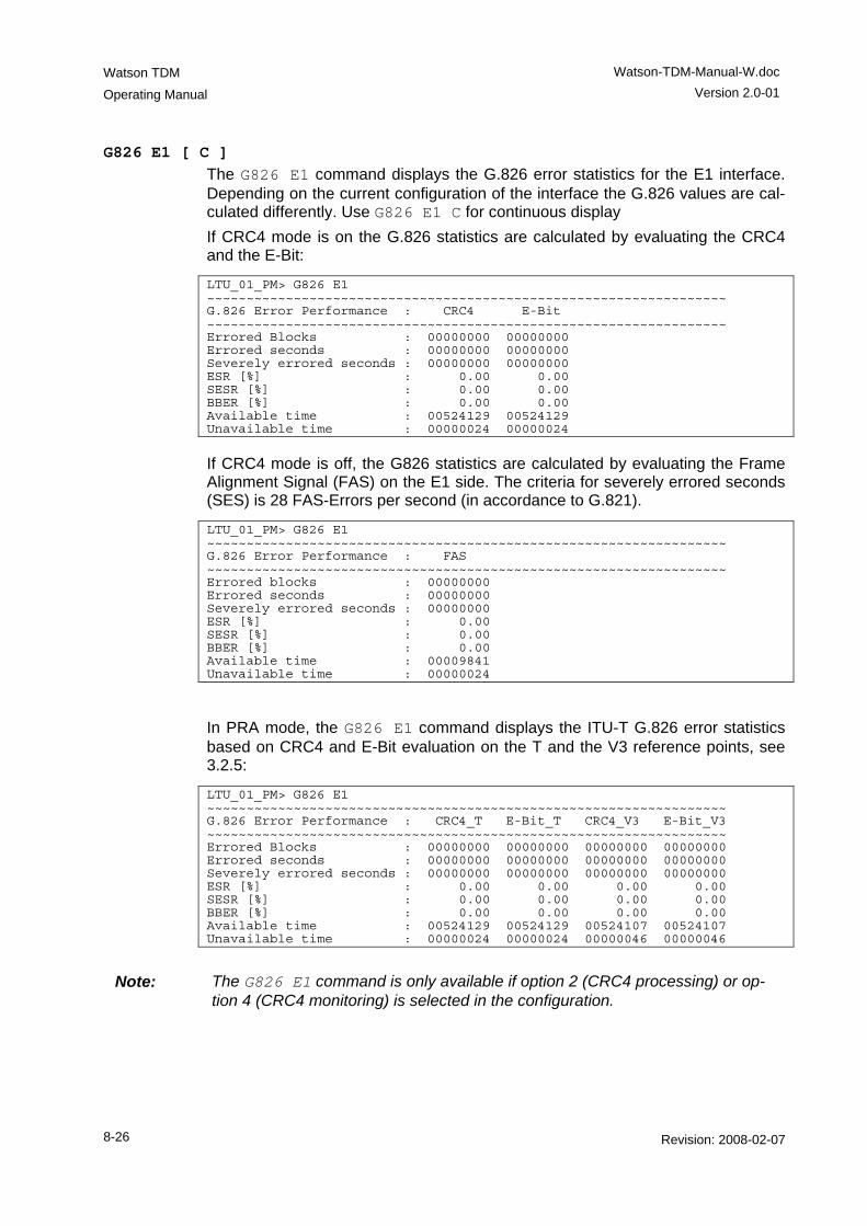
Watson TDM
Operating Manual
Watson-TDM-Manual-W.doc Version 2.0-01
8-26 Revision: 2008-02-07
G826 E1 [ C ] The G826 E1 command displays the G.826 error statistics for the E1 interface. Depending on the current configuration of the interface the G.826 values are cal-culated differently. Use G826 E1 C for continuous display If CRC4 mode is on the G.826 statistics are calculated by evaluating the CRC4 and the E-Bit:
LTU_01_PM> G826 E1 ~~~~~~~~~~~~~~~~~~~~~~~~~~~~~~~~~~~~~~~~~~~~~~~~~~~~~~~~~~~~~~~~~~ G.826 Error Performance : CRC4 E-Bit ~~~~~~~~~~~~~~~~~~~~~~~~~~~~~~~~~~~~~~~~~~~~~~~~~~~~~~~~~~~~~~~~~~ Errored Blocks : 00000000 00000000 Errored seconds : 00000000 00000000 Severely errored seconds : 00000000 00000000 ESR [%] : 0.00 0.00 SESR [%] : 0.00 0.00 BBER [%] : 0.00 0.00 Available time : 00524129 00524129 Unavailable time : 00000024 00000024
If CRC4 mode is off, the G826 statistics are calculated by evaluating the Frame Alignment Signal (FAS) on the E1 side. The criteria for severely errored seconds (SES) is 28 FAS-Errors per second (in accordance to G.821).
LTU_01_PM> G826 E1 ~~~~~~~~~~~~~~~~~~~~~~~~~~~~~~~~~~~~~~~~~~~~~~~~~~~~~~~~~~~~~~~~~~ G.826 Error Performance : FAS ~~~~~~~~~~~~~~~~~~~~~~~~~~~~~~~~~~~~~~~~~~~~~~~~~~~~~~~~~~~~~~~~~~ Errored blocks : 00000000 Errored seconds : 00000000 Severely errored seconds : 00000000 ESR [%] : 0.00 SESR [%] : 0.00 BBER [%] : 0.00 Available time : 00009841 Unavailable time : 00000024
In PRA mode, the G826 E1 command displays the ITU-T G.826 error statistics based on CRC4 and E-Bit evaluation on the T and the V3 reference points, see 3.2.5:
LTU_01_PM> G826 E1 ~~~~~~~~~~~~~~~~~~~~~~~~~~~~~~~~~~~~~~~~~~~~~~~~~~~~~~~~~~~~~~~~~~ G.826 Error Performance : CRC4_T E-Bit_T CRC4_V3 E-Bit_V3 ~~~~~~~~~~~~~~~~~~~~~~~~~~~~~~~~~~~~~~~~~~~~~~~~~~~~~~~~~~~~~~~~~~ Errored Blocks : 00000000 00000000 00000000 00000000 Errored seconds : 00000000 00000000 00000000 00000000 Severely errored seconds : 00000000 00000000 00000000 00000000 ESR [%] : 0.00 0.00 0.00 0.00 SESR [%] : 0.00 0.00 0.00 0.00 BBER [%] : 0.00 0.00 0.00 0.00 Available time : 00524129 00524129 00524107 00524107 Unavailable time : 00000024 00000024 00000046 00000046
Note: The G826 E1 command is only available if option 2 (CRC4 processing) or op-
tion 4 (CRC4 monitoring) is selected in the configuration.
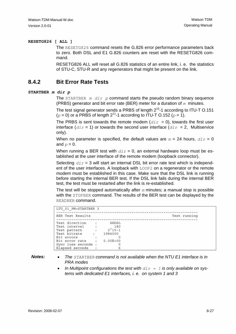
Watson-TDM-Manual-W.doc
Version 2.0-01
Watson TDM Operating Manual
Revision: 2008-02-07 8-27
RESETG826 [ ALL ] The RESETG826 command resets the G.826 error performance parameters back to zero. Both DSL and E1 G.826 counters are reset with the RESETG826 com-mand. RESETG826 ALL will reset all G.826 statistics of an entire link, i. e. the statistics of STU-C, STU-R and any regenerators that might be present on the link.
8.4.2 Bit Error Rate Tests
STARTBER m dir p The STARTBER m dir p command starts the pseudo random binary sequence (PRBS) generator and bit error rate (BER) meter for a duration of m minutes. The test signal generator sends a PRBS of length 215-1 according to ITU-T O.151 (p = 0) or a PRBS of length 211-1 according to ITU-T O.152 (p = 1). The PRBS is sent towards the remote modem (dir = 0), towards the first user interface (dir = 1) or towards the second user interface (dir = 2, Multiservice only). When no parameter is specified, the default values are m = 24 hours, dir = 0 and p = 0. When running a BER test with dir = 0, an external hardware loop must be es-tablished at the user interface of the remote modem (loopback connector). Selecting dir = 3 will start an internal DSL bit error rate test which is independ-ent of the user interfaces. A loopback with LOOP2 on a regenerator or the remote modem must be established in this case. Make sure that the DSL link is running before starting the internal BER test. If the DSL link fails during the internal BER test, the test must be restarted after the link is re-established. The test will be stopped automatically after m minutes; a manual stop is possible with the STOPBER command. The results of the BER test can be displayed by the READBER command.
LTU_01_PM>STARTBER 3 ~~~~~~~~~~~~~~~~~~~~~~~~~~~~~~~~~~~~~~~~~~~~~~~~~~~~~~~~~~~~~~~~~~ BER Test Results Test running ~~~~~~~~~~~~~~~~~~~~~~~~~~~~~~~~~~~~~~~~~~~~~~~~~~~~~~~~~~~~~~~~~~ Test direction : SHDSL Test interval : 180 Test pattern : 2^15-1 Test bitrate : 1984000 Bit errors : 0 Bit error rate : 0.00E+00 Sync loss seconds : 0 Elapsed seconds : 6
Notes: • The STARTBER command is not available when the NTU E1 interface is in PRA modes
• In Multipoint configurations the test with dir = 1 is only available on sys-tems with dedicated E1 interfaces, i. e. on system 1 and 3
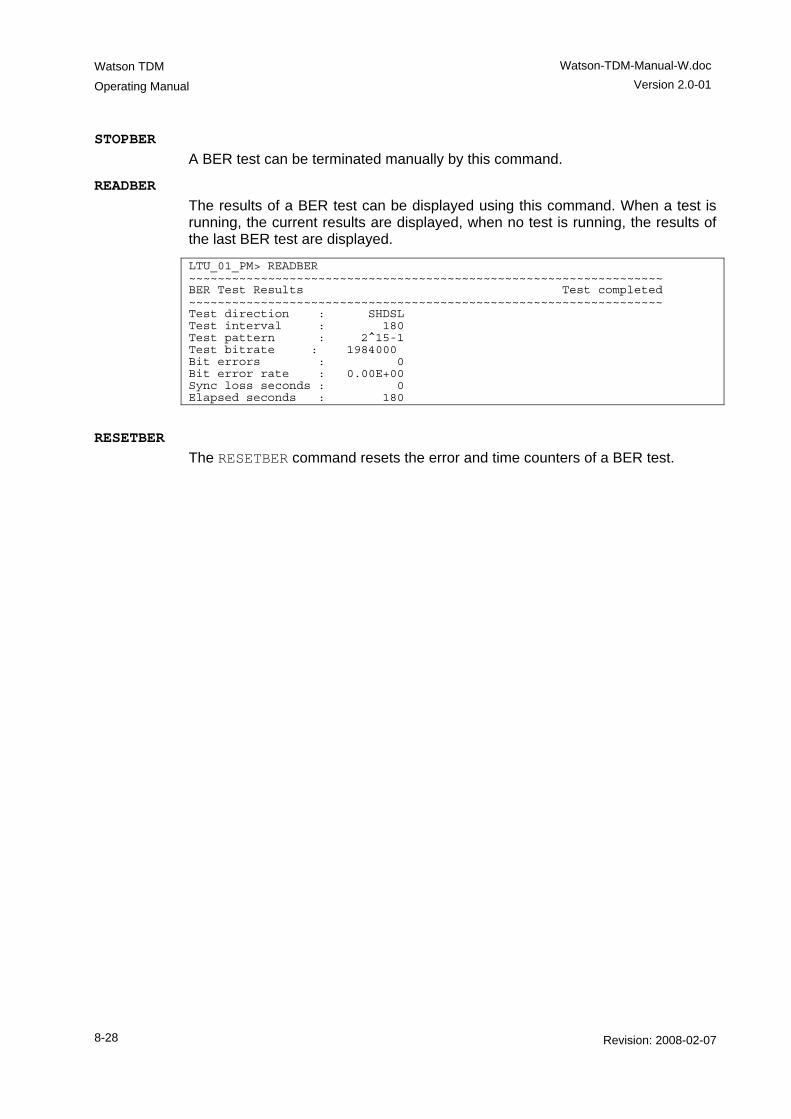
Watson TDM
Operating Manual
Watson-TDM-Manual-W.doc Version 2.0-01
8-28 Revision: 2008-02-07
STOPBER A BER test can be terminated manually by this command.
READBER The results of a BER test can be displayed using this command. When a test is running, the current results are displayed, when no test is running, the results of the last BER test are displayed.
LTU_01_PM> READBER ~~~~~~~~~~~~~~~~~~~~~~~~~~~~~~~~~~~~~~~~~~~~~~~~~~~~~~~~~~~~~~~~~~ BER Test Results Test completed ~~~~~~~~~~~~~~~~~~~~~~~~~~~~~~~~~~~~~~~~~~~~~~~~~~~~~~~~~~~~~~~~~~ Test direction : SHDSL Test interval : 180 Test pattern : 2^15-1 Test bitrate : 1984000 Bit errors : 0 Bit error rate : 0.00E+00 Sync loss seconds : 0 Elapsed seconds : 180
RESETBER The RESETBER command resets the error and time counters of a BER test.
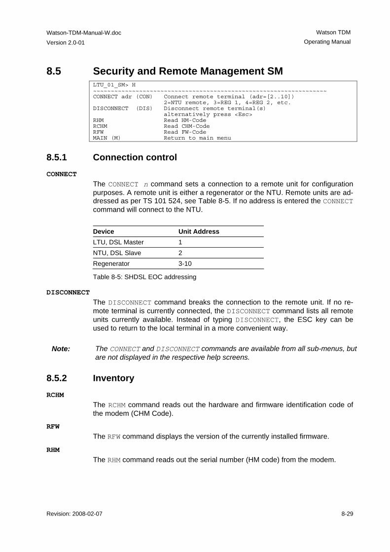
Watson-TDM-Manual-W.doc
Version 2.0-01
Watson TDM Operating Manual
Revision: 2008-02-07 8-29
8.5 Security and Remote Management SM LTU_01_SM> H ~~~~~~~~~~~~~~~~~~~~~~~~~~~~~~~~~~~~~~~~~~~~~~~~~~~~~~~~~~~~~~~~~~ CONNECT adr (CON) Connect remote terminal (adr=[2..10]) 2=NTU remote, 3=REG 1, 4=REG 2, etc. DISCONNECT (DIS) Disconnect remote terminal(s) alternatively press <Esc> RHM Read HM-Code RCHM Read CHM-Code RFW Read FW-Code MAIN (M) Return to main menu
8.5.1 Connection control CONNECT
The CONNECT n command sets a connection to a remote unit for configuration purposes. A remote unit is either a regenerator or the NTU. Remote units are ad-dressed as per TS 101 524, see Table 8-5. If no address is entered the CONNECT command will connect to the NTU. Device Unit Address LTU, DSL Master 1 NTU, DSL Slave 2 Regenerator 3-10
Table 8-5: SHDSL EOC addressing
DISCONNECT The DISCONNECT command breaks the connection to the remote unit. If no re-mote terminal is currently connected, the DISCONNECT command lists all remote units currently available. Instead of typing DISCONNECT, the ESC key can be used to return to the local terminal in a more convenient way.
Note: The CONNECT and DISCONNECT commands are available from all sub-menus, but are not displayed in the respective help screens.
8.5.2 Inventory RCHM
The RCHM command reads out the hardware and firmware identification code of the modem (CHM Code).
RFW The RFW command displays the version of the currently installed firmware.
RHM The RHM command reads out the serial number (HM code) from the modem.
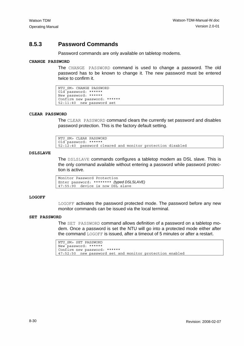
Watson TDM
Operating Manual
Watson-TDM-Manual-W.doc Version 2.0-01
8-30 Revision: 2008-02-07
8.5.3 Password Commands Password commands are only available on tabletop modems.
CHANGE PASSWORD The CHANGE PASSWORD command is used to change a password. The old password has to be known to change it. The new password must be entered twice to confirm it. NTU_SM> CHANGE PASSWORD Old password: ****** New password: ****** Confirm new password: ****** 52:11:40 new password set
CLEAR PASSWORD The CLEAR PASSWORD command clears the currently set password and disables password protection. This is the factory default setting. NTU_SM> CLEAR PASSWORD Old password: ****** 52:12:40 password cleared and monitor protection disabled
DSLSLAVE The DSLSLAVE commands configures a tabletop modem as DSL slave. This is the only command available without entering a password while password protec-tion is active.
Monitor Password Protection Enter password: ******** (typed DSLSLAVE) 47:55:90 device is now DSL slave
LOGOFF LOGOFF activates the password protected mode. The password before any new monitor commands can be issued via the local terminal.
SET PASSWORD The SET PASSWORD command allows definition of a password on a tabletop mo-dem. Once a password is set the NTU will go into a protected mode either after the command LOGOFF is issued, after a timeout of 5 minutes or after a restart.
NTU_SM> SET PASSWORD New password: ****** Confirm new password: ****** 47:52:50 new password set and monitor protection enabled
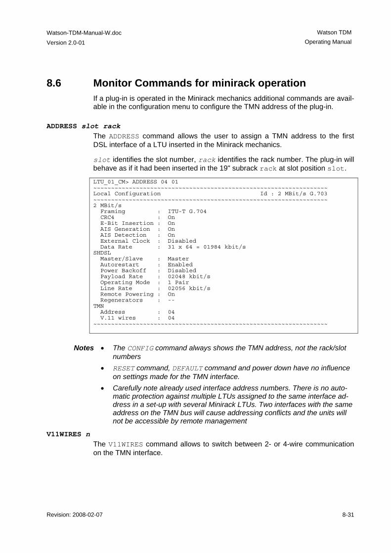
Watson-TDM-Manual-W.doc
Version 2.0-01
Watson TDM Operating Manual
Revision: 2008-02-07 8-31
8.6 Monitor Commands for minirack operation If a plug-in is operated in the Minirack mechanics additional commands are avail-able in the configuration menu to configure the TMN address of the plug-in.
ADDRESS slot rack The ADDRESS command allows the user to assign a TMN address to the first DSL interface of a LTU inserted in the Minirack mechanics.
slot identifies the slot number, rack identifies the rack number. The plug-in will behave as if it had been inserted in the 19" subrack rack at slot position slot.
LTU_01_CM> ADDRESS 04 01 ~~~~~~~~~~~~~~~~~~~~~~~~~~~~~~~~~~~~~~~~~~~~~~~~~~~~~~~~~~~~~~~~~~ Local Configuration Id : 2 MBit/s G.703 ~~~~~~~~~~~~~~~~~~~~~~~~~~~~~~~~~~~~~~~~~~~~~~~~~~~~~~~~~~~~~~~~~~ 2 MBit/s Framing : ITU-T G.704 CRC4 : On E-Bit Insertion : On AIS Generation : On AIS Detection : On External Clock : Disabled Data Rate : 31 x 64 = 01984 kbit/s SHDSL Master/Slave : Master Autorestart : Enabled Power Backoff : Disabled Payload Rate : 02048 kbit/s Operating Mode : 1 Pair Line Rate : 02056 kbit/s Remote Powering : On Regenerators : -- TMN Address : 04 V.11 wires : 04 ~~~~~~~~~~~~~~~~~~~~~~~~~~~~~~~~~~~~~~~~~~~~~~~~~~~~~~~~~~~~~~~~~~
Notes • The CONFIG command always shows the TMN address, not the rack/slot
numbers • RESET command, DEFAULT command and power down have no influence
on settings made for the TMN interface. • Carefully note already used interface address numbers. There is no auto-
matic protection against multiple LTUs assigned to the same interface ad-dress in a set-up with several Minirack LTUs. Two interfaces with the same address on the TMN bus will cause addressing conflicts and the units will not be accessible by remote management
V11WIRES n The V11WIRES command allows to switch between 2- or 4-wire communication on the TMN interface.
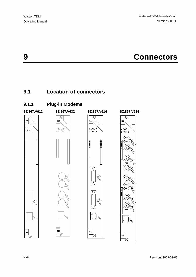
Watson TDM
Operating Manual
Watson-TDM-Manual-W.doc Version 2.0-01
9-32 Revision: 2008-02-07
9 Connectors
9.1 Location of connectors
9.1.1 Plug-in Modems SZ.867.V612 SZ.867.V632 SZ.867.V614 SZ.867.V634
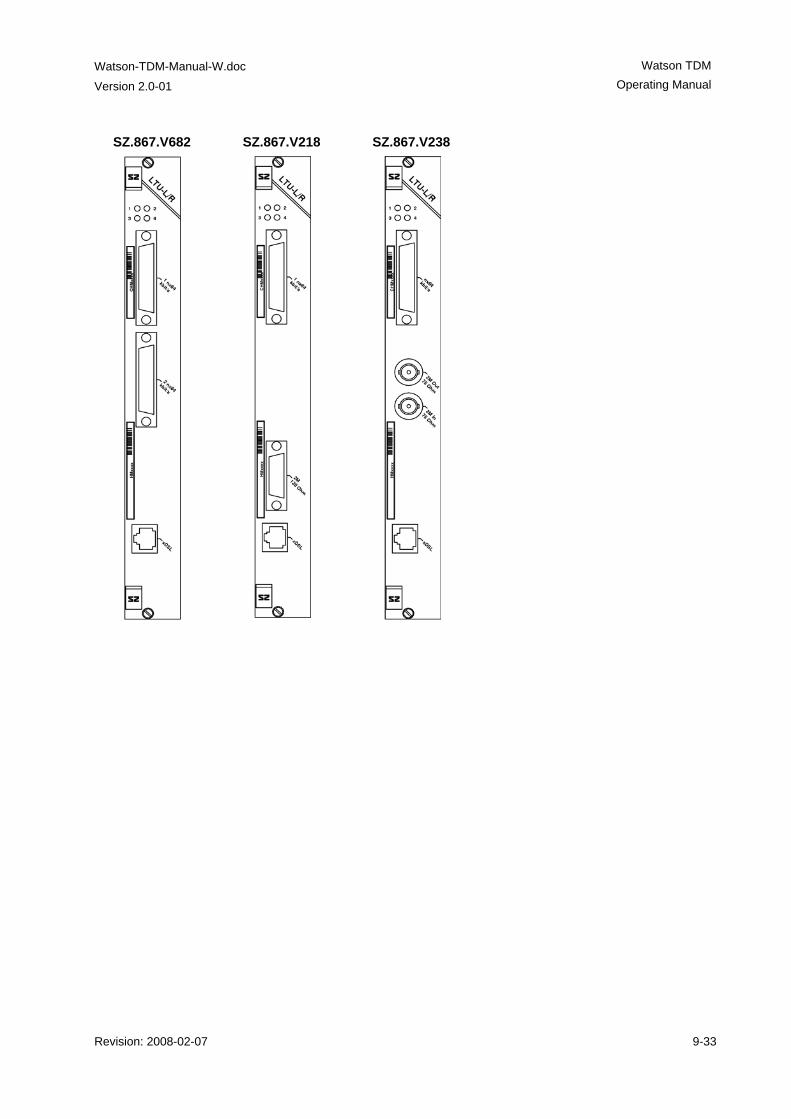
Watson-TDM-Manual-W.doc
Version 2.0-01
Watson TDM Operating Manual
Revision: 2008-02-07 9-33
SZ.867.V682 SZ.867.V218 SZ.867.V238
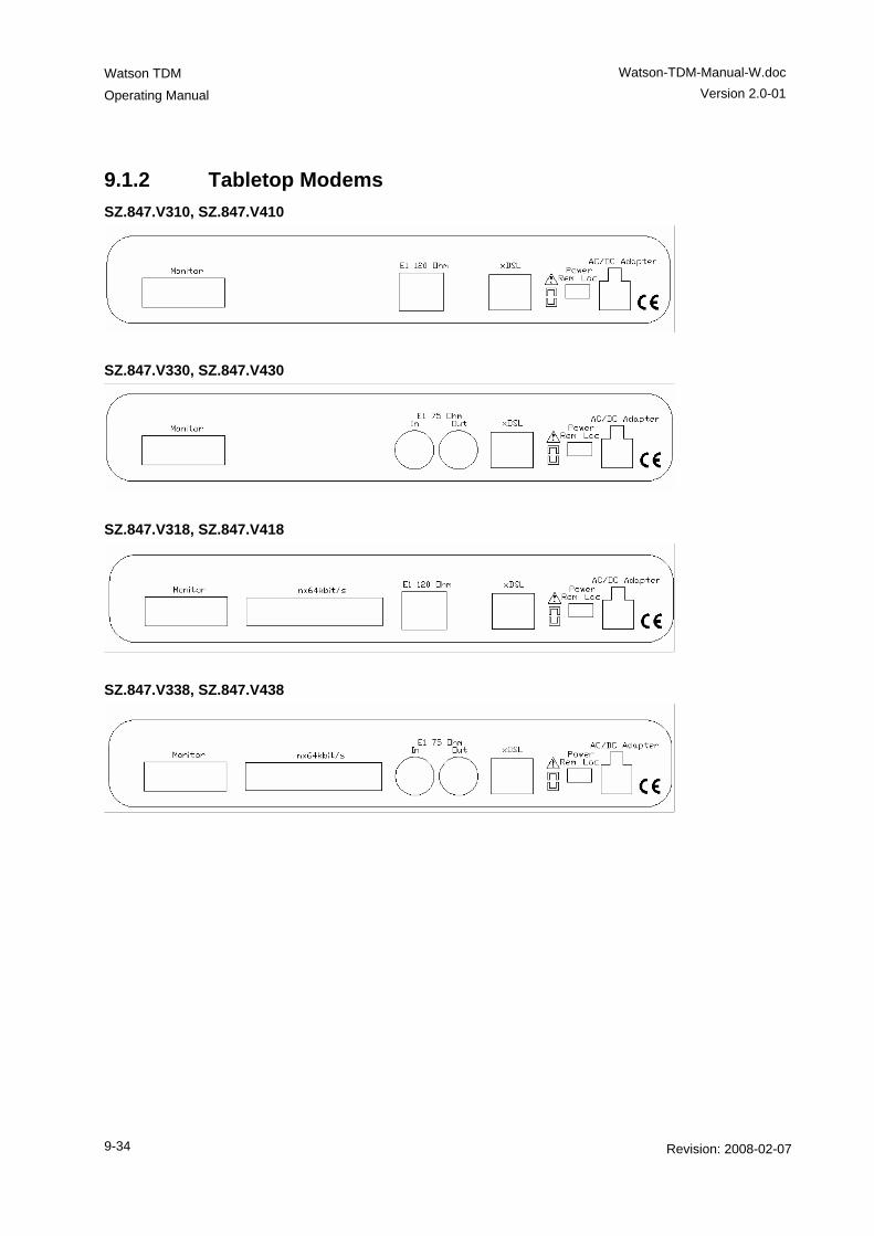
Watson TDM
Operating Manual
Watson-TDM-Manual-W.doc Version 2.0-01
9-34 Revision: 2008-02-07
9.1.2 Tabletop Modems SZ.847.V310, SZ.847.V410
SZ.847.V330, SZ.847.V430
SZ.847.V318, SZ.847.V418
SZ.847.V338, SZ.847.V438
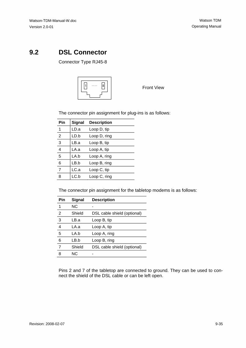
Watson-TDM-Manual-W.doc
Version 2.0-01
Watson TDM Operating Manual
Revision: 2008-02-07 9-35
9.2 DSL Connector Connector Type RJ45-8
1 8. . . .
Front View
The connector pin assignment for plug-ins is as follows:
Pin Signal Description 1 LD.a Loop D, tip 2 LD.b Loop D, ring 3 LB.a Loop B, tip 4 LA.a Loop A, tip 5 LA.b Loop A, ring 6 LB.b Loop B, ring 7 LC.a Loop C, tip 8 LC.b Loop C, ring
The connector pin assignment for the tabletop modems is as follows:
Pin Signal Description 1 NC - 2 Shield DSL cable shield (optional) 3 LB.a Loop B, tip 4 LA.a Loop A, tip 5 LA.b Loop A, ring 6 LB.b Loop B, ring 7 Shield DSL cable shield (optional) 8 NC -
Pins 2 and 7 of the tabletop are connected to ground. They can be used to con-nect the shield of the DSL cable or can be left open.
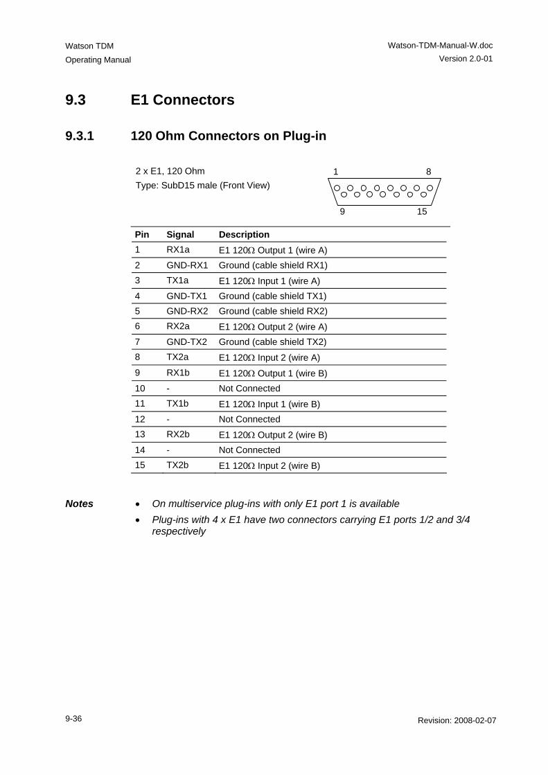
Watson TDM
Operating Manual
Watson-TDM-Manual-W.doc Version 2.0-01
9-36 Revision: 2008-02-07
9.3 E1 Connectors
9.3.1 120 Ohm Connectors on Plug-in 2 x E1, 120 Ohm Type: SubD15 male (Front View)
1 8
9 15
Pin Signal Description 1 RX1a E1 120Ω Output 1 (wire A) 2 GND-RX1 Ground (cable shield RX1) 3 TX1a E1 120Ω Input 1 (wire A) 4 GND-TX1 Ground (cable shield TX1) 5 GND-RX2 Ground (cable shield RX2) 6 RX2a E1 120Ω Output 2 (wire A) 7 GND-TX2 Ground (cable shield TX2) 8 TX2a E1 120Ω Input 2 (wire A) 9 RX1b E1 120Ω Output 1 (wire B) 10 - Not Connected 11 TX1b E1 120Ω Input 1 (wire B) 12 - Not Connected 13 RX2b E1 120Ω Output 2 (wire B) 14 - Not Connected 15 TX2b E1 120Ω Input 2 (wire B)
Notes • On multiservice plug-ins with only E1 port 1 is available • Plug-ins with 4 x E1 have two connectors carrying E1 ports 1/2 and 3/4
respectively
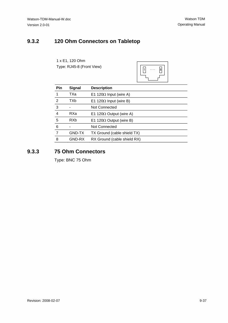
Watson-TDM-Manual-W.doc
Version 2.0-01
Watson TDM Operating Manual
Revision: 2008-02-07 9-37
9.3.2 120 Ohm Connectors on Tabletop
1 x E1, 120 Ohm Type: RJ45-8 (Front View)
1 8. . . .
Pin Signal Description 1 TXa E1 120Ω Input (wire A) 2 TXb E1 120Ω Input (wire B) 3 - Not Connected 4 RXa E1 120Ω Output (wire A) 5 RXb E1 120Ω Output (wire B) 6 - Not Connected 7 GND-TX TX Ground (cable shield TX) 8 GND-RX RX Ground (cable shield RX)
9.3.3 75 Ohm Connectors Type: BNC 75 Ohm
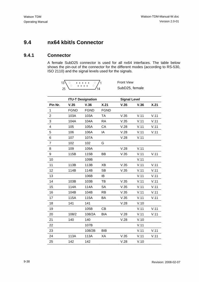
Watson TDM
Operating Manual
Watson-TDM-Manual-W.doc Version 2.0-01
9-38 Revision: 2008-02-07
9.4 nx64 kbit/s Connector
9.4.1 Connector A female SubD25 connector is used for all nx64 interfaces. The table below shows the pin-out of the connector for the different modes (according to RS-530, ISO 2110) and the signal levels used for the signals.
13 1
25 14
Front View
SubD25, female
ITU-T Designation Signal Level Pin Nr. V.35 V.36 X.21 V.35 V.36 X.21 1 FGND FGND FGND 2 103A 103A TA V.35 V.11 V.11 3 104A 104A RA V.35 V.11 V.11 4 105 105A CA V.28 V.11 V.11 5 106 106A IA V.28 V.11 V.11 6 107 107A V.28 V.11 7 102 102 G 8 109 109A V.28 V.11 9 115B 115B BB V.35 V.11 V.11 10 109B V.11 11 113B 113B XB V.35 V.11 V.11 12 114B 114B SB V.35 V.11 V.11 13 106B IB V.11 V.11 14 103B 103B TB V.35 V.11 V.11 15 114A 114A SA V.35 V.11 V.11 16 104B 104B RB V.35 V.11 V.11 17 115A 115A BA V.35 V.11 V.11 18 141 141 V.28 V.10 19 105B CB V.11 V.11 20 108/2 108/2A BIA V.28 V.11 V.11 21 140 140 V.28 V.10 22 107B V.11 23 108/2B BIB V.11 V.11 24 113A 113A XA V.35 V.11 V.11 25 142 142 V.28 V.10
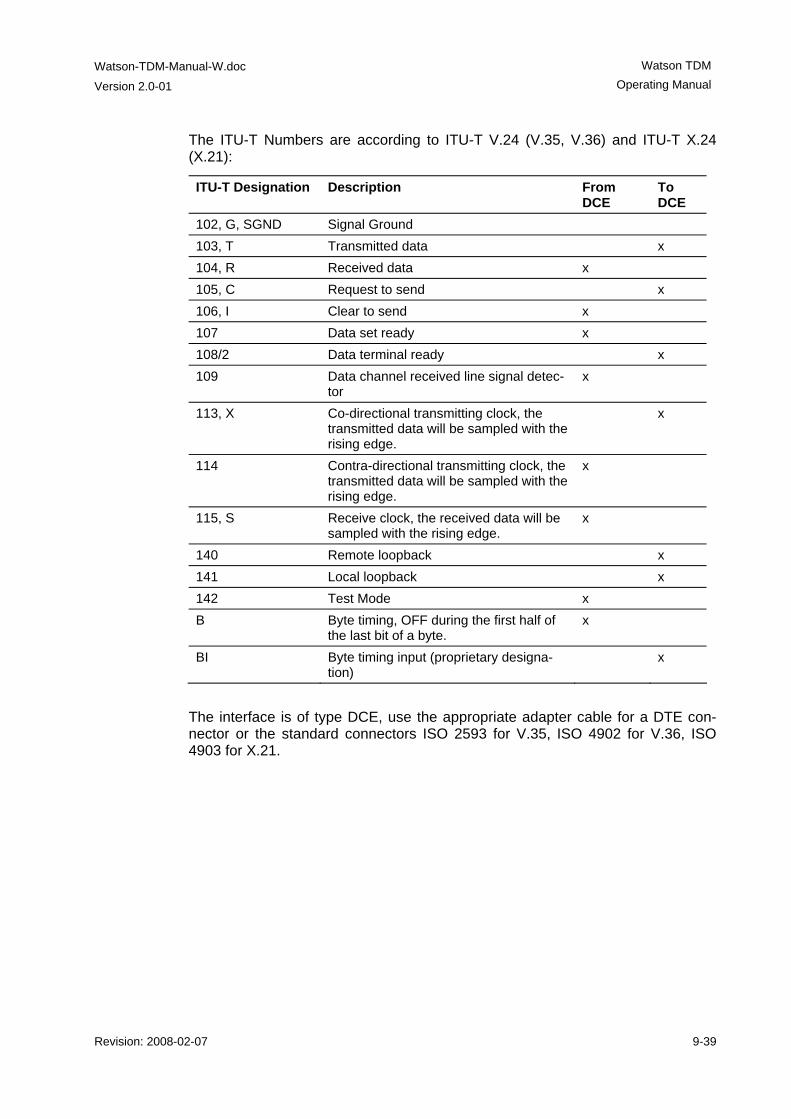
Watson-TDM-Manual-W.doc
Version 2.0-01
Watson TDM Operating Manual
Revision: 2008-02-07 9-39
The ITU-T Numbers are according to ITU-T V.24 (V.35, V.36) and ITU-T X.24 (X.21):
ITU-T Designation Description From DCE
To DCE
102, G, SGND Signal Ground 103, T Transmitted data x 104, R Received data x 105, C Request to send x 106, I Clear to send x 107 Data set ready x 108/2 Data terminal ready x 109 Data channel received line signal detec-
tor x
113, X Co-directional transmitting clock, the transmitted data will be sampled with the rising edge.
x
114 Contra-directional transmitting clock, the transmitted data will be sampled with the rising edge.
x
115, S Receive clock, the received data will be sampled with the rising edge.
x
140 Remote loopback x 141 Local loopback x 142 Test Mode x B Byte timing, OFF during the first half of
the last bit of a byte. x
BI Byte timing input (proprietary designa-tion)
x
The interface is of type DCE, use the appropriate adapter cable for a DTE con-nector or the standard connectors ISO 2593 for V.35, ISO 4902 for V.36, ISO 4903 for X.21.
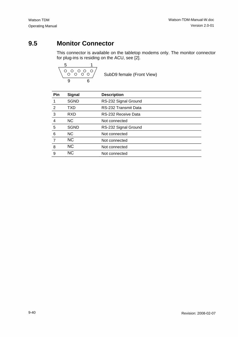
Watson TDM
Operating Manual
Watson-TDM-Manual-W.doc Version 2.0-01
9-40 Revision: 2008-02-07
9.5 Monitor Connector This connector is available on the tabletop modems only. The monitor connector for plug-ins is residing on the ACU, see [2].
SubD9 female (Front View)
Pin Signal Description 1 SGND RS-232 Signal Ground 2 TXD RS-232 Transmit Data 3 RXD RS-232 Receive Data 4 NC Not connected 5 SGND RS-232 Signal Ground 6 NC Not connected 7 NC Not connected 8 NC Not connected 9 NC Not connected
5 1
9 6
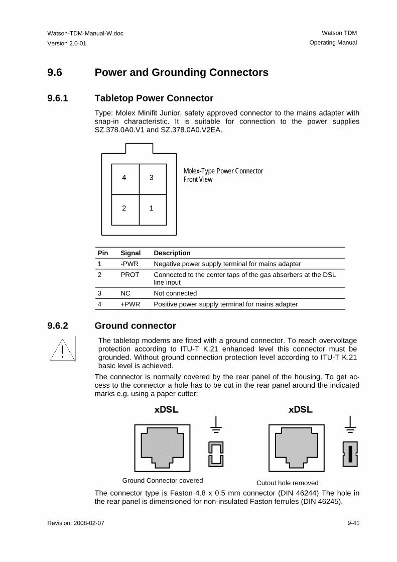
Watson-TDM-Manual-W.doc
Version 2.0-01
Watson TDM Operating Manual
Revision: 2008-02-07 9-41
9.6 Power and Grounding Connectors
9.6.1 Tabletop Power Connector Type: Molex Minifit Junior, safety approved connector to the mains adapter with snap-in characteristic. It is suitable for connection to the power supplies SZ.378.0A0.V1 and SZ.378.0A0.V2EA.
Pin Signal Description 1 -PWR Negative power supply terminal for mains adapter 2 PROT Connected to the center taps of the gas absorbers at the DSL
line input 3 NC Not connected 4 +PWR Positive power supply terminal for mains adapter
9.6.2 Ground connector
The tabletop modems are fitted with a ground connector. To reach overvoltage protection according to ITU-T K.21 enhanced level this connector must be grounded. Without ground connection protection level according to ITU-T K.21 basic level is achieved.
The connector is normally covered by the rear panel of the housing. To get ac-cess to the connector a hole has to be cut in the rear panel around the indicated marks e.g. using a paper cutter:
Ground Connector covered Cutout hole removed The connector type is Faston 4.8 x 0.5 mm connector (DIN 46244) The hole in the rear panel is dimensioned for non-insulated Faston ferrules (DIN 46245).
Molex-Type Power Connector Front View 4 3
2 1
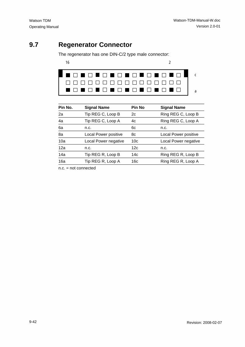
Watson TDM
Operating Manual
Watson-TDM-Manual-W.doc Version 2.0-01
9-42 Revision: 2008-02-07
9.7 Regenerator Connector The regenerator has one DIN-C/2 type male connector: 216
c
a
Pin No. Signal Name Pin No Signal Name 2a Tip REG C, Loop B 2c Ring REG C, Loop B 4a Tip REG C, Loop A 4c Ring REG C, Loop A 6a n.c. 6c n.c. 8a Local Power positive 8c Local Power positive 10a Local Power negative 10c Local Power negative 12a n.c. 12c n.c. 14a Tip REG R, Loop B 14c Ring REG R, Loop B 16a Tip REG R, Loop A 16c Ring REG R, Loop A n.c. = not connected
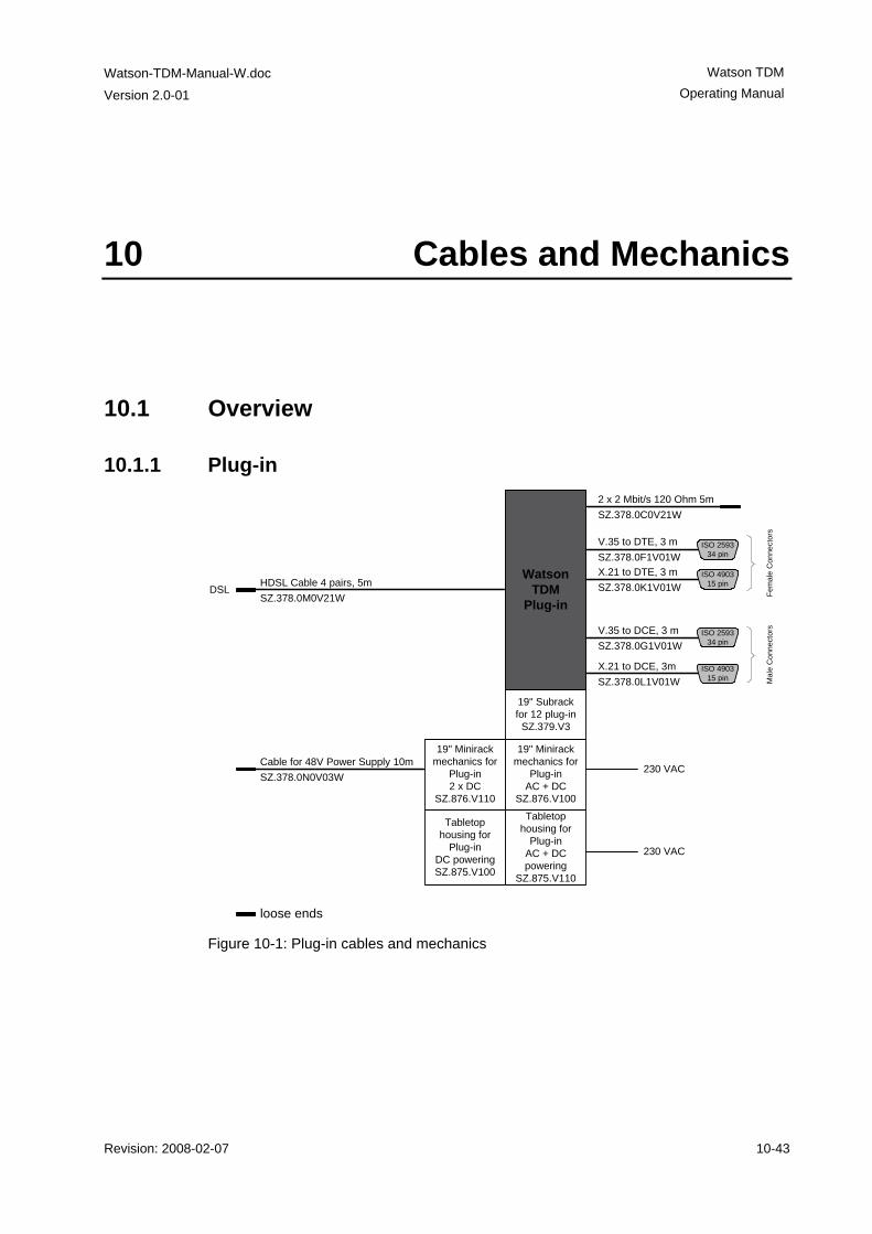
Watson-TDM-Manual-W.doc
Version 2.0-01
Watson TDM Operating Manual
Revision: 2008-02-07 10-43
10 Cables and Mechanics
10.1 Overview
10.1.1 Plug-in
Cable for 48V Power Supply 10mSZ.378.0N0V03W
2 x 2 Mbit/s 120 Ohm 5mSZ.378.0C0V21W
HDSL Cable 4 pairs, 5mSZ.378.0M0V21W
V.35 to DTE, 3 mSZ.378.0F1V01WX.21 to DTE, 3 mSZ.378.0K1V01W
V.35 to DCE, 3 mSZ.378.0G1V01W
X.21 to DCE, 3mSZ.378.0L1V01W
Fem
ale
Con
nect
ors
loose ends
ISO 259334 pin
ISO 259334 pin
ISO 490315 pin
ISO 490315 pin M
ale
Con
nect
ors
Watson TDM
Plug-inDSL
19" Minirack mechanics for
Plug-inAC + DC
SZ.876.V100
19" Subrack for 12 plug-in
SZ.379.V3
19" Minirack mechanics for
Plug-in2 x DC
SZ.876.V110
Tabletop housing for
Plug-inAC + DC powering
SZ.875.V110
Tabletop housing for
Plug-inDC poweringSZ.875.V100
230 VAC
230 VAC
Figure 10-1: Plug-in cables and mechanics
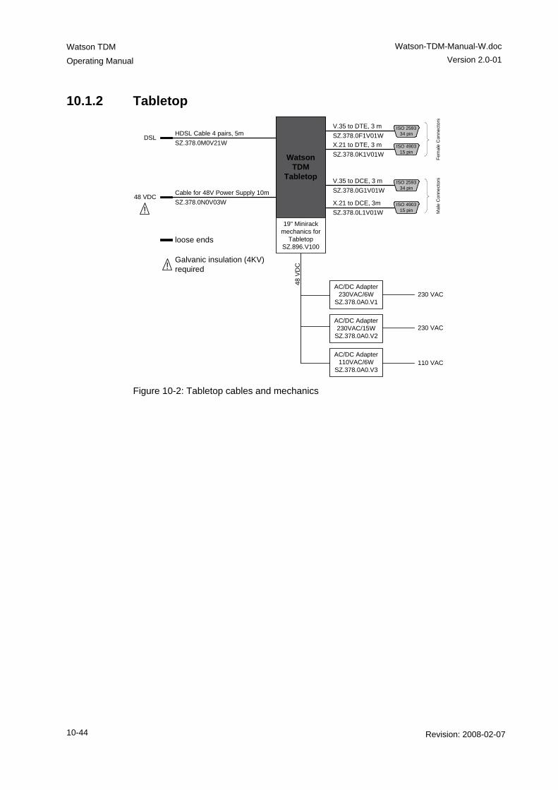
Watson TDM
Operating Manual
Watson-TDM-Manual-W.doc Version 2.0-01
10-44 Revision: 2008-02-07
10.1.2 Tabletop
Cable for 48V Power Supply 10mSZ.378.0N0V03W
48 VDC
HDSL Cable 4 pairs, 5mSZ.378.0M0V21W
V.35 to DTE, 3 mSZ.378.0F1V01WX.21 to DTE, 3 mSZ.378.0K1V01W
V.35 to DCE, 3 mSZ.378.0G1V01W
X.21 to DCE, 3mSZ.378.0L1V01W
Fem
ale
Con
nect
ors
loose ends
ISO 259334 pin
ISO 259334 pin
ISO 490315 pin
ISO 490315 pin M
ale
Con
nect
ors
Watson TDM
Tabletop
AC/DC Adapter 230VAC/6W
SZ.378.0A0.V1
DSL
!
!Galvanic insulation (4KV) required
AC/DC Adapter 230VAC/15W
SZ.378.0A0.V2
AC/DC Adapter 110VAC/6W
SZ.378.0A0.V3
230 VAC
230 VAC
110 VAC
48 V
DC
19" Minirack mechanics for
TabletopSZ.896.V100
Figure 10-2: Tabletop cables and mechanics
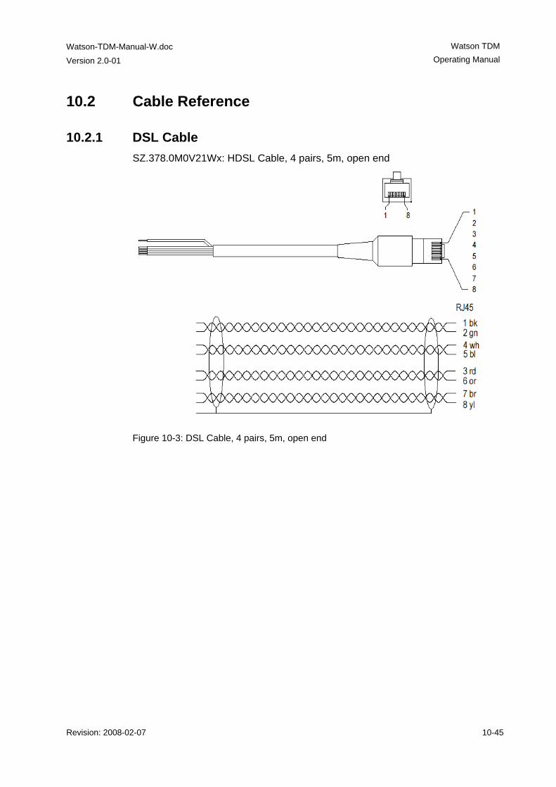
Watson-TDM-Manual-W.doc
Version 2.0-01
Watson TDM Operating Manual
Revision: 2008-02-07 10-45
10.2 Cable Reference
10.2.1 DSL Cable SZ.378.0M0V21Wx: HDSL Cable, 4 pairs, 5m, open end
Figure 10-3: DSL Cable, 4 pairs, 5m, open end
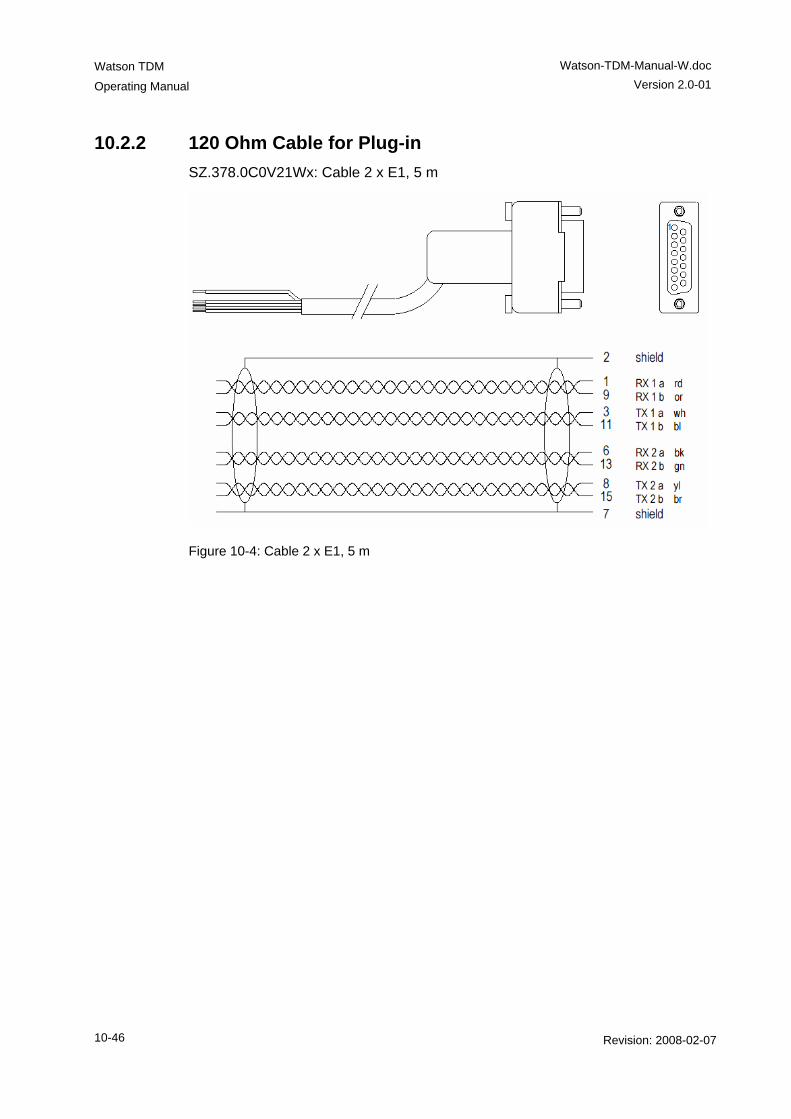
Watson TDM
Operating Manual
Watson-TDM-Manual-W.doc Version 2.0-01
10-46 Revision: 2008-02-07
10.2.2 120 Ohm Cable for Plug-in SZ.378.0C0V21Wx: Cable 2 x E1, 5 m
Figure 10-4: Cable 2 x E1, 5 m
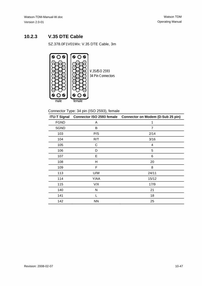
Watson-TDM-Manual-W.doc
Version 2.0-01
Watson TDM Operating Manual
Revision: 2008-02-07 10-47
10.2.3 V.35 DTE Cable SZ.378.0F1V01Wx: V.35 DTE Cable, 3m
Connector Type: 34 pin (ISO 2593), female ITU-T Signal Connector ISO 2593 female Connector on Modem (D-Sub 25 pin)
FGND A 1 SGND B 7
103 P/S 2/14 104 R/T 3/16 105 C 4 106 D 5 107 E 6 108 H 20 109 F 8 113 U/W 24/11 114 Y/AA 15/12 115 V/X 17/9 140 N 21 141 L 18 142 NN 25
V.35/ISO 2593 34 Pin Connectors
AA
A BC D
E FH
LN
P S R
T U
W Y X V
NN
C H
S W
A
E
P
U
D
N T X
B
L R V
NN
female male
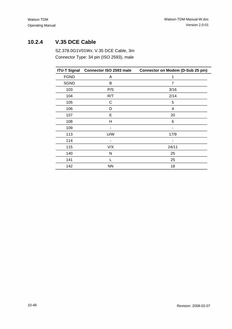
Watson TDM
Operating Manual
Watson-TDM-Manual-W.doc Version 2.0-01
10-48 Revision: 2008-02-07
10.2.4 V.35 DCE Cable SZ.378.0G1V01Wx: V.35 DCE Cable, 3m Connector Type: 34 pin (ISO 2593), male ITU-T Signal Connector ISO 2593 male Connector on Modem (D-Sub 25 pin)
FGND A 1 SGND B 7
103 P/S 3/16 104 R/T 2/14 105 C 5 106 D 4 107 E 20 108 H 6 109 - - 113 U/W 17/9 114 - - 115 V/X 24/11 140 N 25 141 L 25 142 NN 18
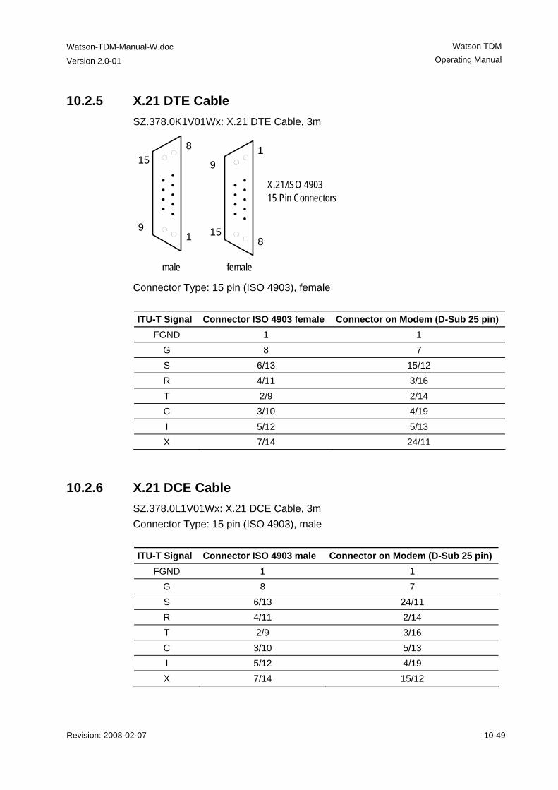
Watson-TDM-Manual-W.doc
Version 2.0-01
Watson TDM Operating Manual
Revision: 2008-02-07 10-49
10.2.5 X.21 DTE Cable SZ.378.0K1V01Wx: X.21 DTE Cable, 3m
Connector Type: 15 pin (ISO 4903), female ITU-T Signal Connector ISO 4903 female Connector on Modem (D-Sub 25 pin)
FGND 1 1 G 8 7 S 6/13 15/12 R 4/11 3/16 T 2/9 2/14 C 3/10 4/19 I 5/12 5/13 X 7/14 24/11
10.2.6 X.21 DCE Cable SZ.378.0L1V01Wx: X.21 DCE Cable, 3m Connector Type: 15 pin (ISO 4903), male ITU-T Signal Connector ISO 4903 male Connector on Modem (D-Sub 25 pin)
FGND 1 1 G 8 7 S 6/13 24/11 R 4/11 2/14 T 2/9 3/16 C 3/10 5/13 I 5/12 4/19 X 7/14 15/12
8
1
15
9
X.21/ISO 4903 15 Pin Connectors
female male
19
15 8

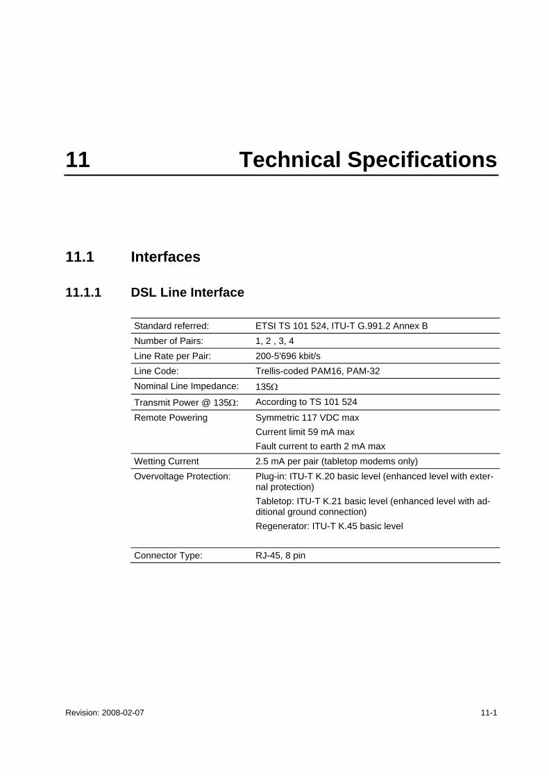
Revision: 2008-02-07 11-1
11 Technical Specifications
11.1 Interfaces
11.1.1 DSL Line Interface
Standard referred: ETSI TS 101 524, ITU-T G.991.2 Annex B Number of Pairs: 1, 2 , 3, 4 Line Rate per Pair: 200-5'696 kbit/s Line Code: Trellis-coded PAM16, PAM-32 Nominal Line Impedance: 135Ω
Transmit Power @ 135Ω: According to TS 101 524
Remote Powering Symmetric 117 VDC max Current limit 59 mA max Fault current to earth 2 mA max
Wetting Current 2.5 mA per pair (tabletop modems only) Overvoltage Protection: Plug-in: ITU-T K.20 basic level (enhanced level with exter-
nal protection) Tabletop: ITU-T K.21 basic level (enhanced level with ad-ditional ground connection) Regenerator: ITU-T K.45 basic level
Connector Type: RJ-45, 8 pin
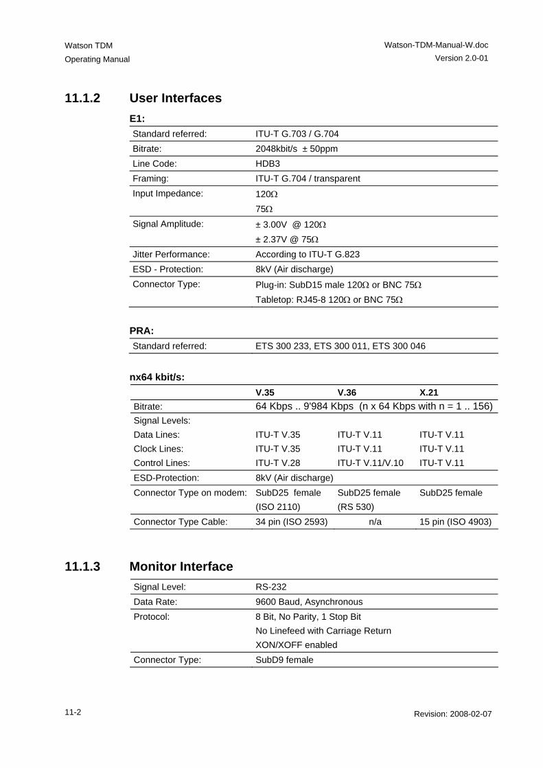
Watson TDM
Operating Manual
Watson-TDM-Manual-W.doc Version 2.0-01
11-2 Revision: 2008-02-07
11.1.2 User Interfaces E1: Standard referred: ITU-T G.703 / G.704 Bitrate: 2048kbit/s ± 50ppm Line Code: HDB3 Framing: ITU-T G.704 / transparent Input Impedance: 120Ω
75Ω Signal Amplitude: ± 3.00V @ 120Ω
± 2.37V @ 75Ω Jitter Performance: According to ITU-T G.823 ESD - Protection: 8kV (Air discharge) Connector Type: Plug-in: SubD15 male 120Ω or BNC 75Ω
Tabletop: RJ45-8 120Ω or BNC 75Ω
PRA: Standard referred: ETS 300 233, ETS 300 011, ETS 300 046
nx64 kbit/s: V.35 V.36 X.21 Bitrate: 64 Kbps .. 9'984 Kbps (n x 64 Kbps with n = 1 .. 156)Signal Levels: Data Lines: Clock Lines: Control Lines:
ITU-T V.35 ITU-T V.35 ITU-T V.28
ITU-T V.11 ITU-T V.11 ITU-T V.11/V.10
ITU-T V.11 ITU-T V.11 ITU-T V.11
ESD-Protection: 8kV (Air discharge) Connector Type on modem: SubD25 female
(ISO 2110) SubD25 female (RS 530)
SubD25 female
Connector Type Cable: 34 pin (ISO 2593) n/a 15 pin (ISO 4903)
11.1.3 Monitor Interface Signal Level: RS-232 Data Rate: 9600 Baud, Asynchronous Protocol: 8 Bit, No Parity, 1 Stop Bit
No Linefeed with Carriage Return XON/XOFF enabled
Connector Type: SubD9 female
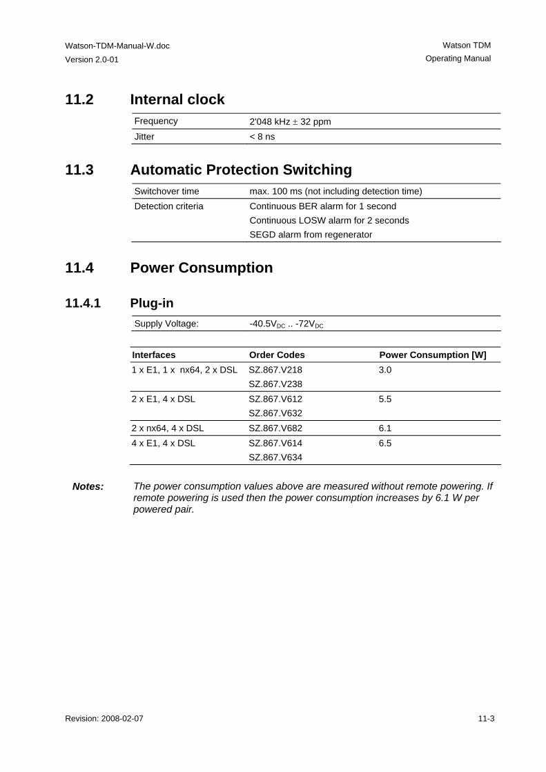
Watson-TDM-Manual-W.doc
Version 2.0-01
Watson TDM Operating Manual
Revision: 2008-02-07 11-3
11.2 Internal clock Frequency 2'048 kHz ± 32 ppm Jitter < 8 ns
11.3 Automatic Protection Switching Switchover time max. 100 ms (not including detection time) Detection criteria Continuous BER alarm for 1 second
Continuous LOSW alarm for 2 seconds SEGD alarm from regenerator
11.4 Power Consumption
11.4.1 Plug-in Supply Voltage: -40.5VDC .. -72VDC
Interfaces Order Codes Power Consumption [W] 1 x E1, 1 x nx64, 2 x DSL SZ.867.V218
SZ.867.V238 3.0
2 x E1, 4 x DSL SZ.867.V612 SZ.867.V632
5.5
2 x nx64, 4 x DSL SZ.867.V682 6.1 4 x E1, 4 x DSL SZ.867.V614
SZ.867.V634 6.5
Notes: The power consumption values above are measured without remote powering. If
remote powering is used then the power consumption increases by 6.1 W per powered pair.
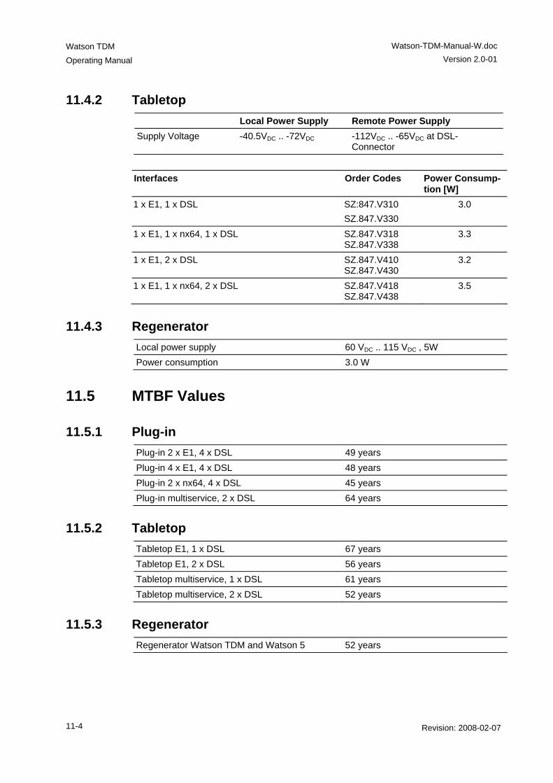
Watson TDM
Operating Manual
Watson-TDM-Manual-W.doc Version 2.0-01
11-4 Revision: 2008-02-07
11.4.2 Tabletop Local Power Supply Remote Power Supply Supply Voltage -40.5VDC .. -72VDC -112VDC .. -65VDC at DSL-
Connector
Interfaces Order Codes Power Consump-
tion [W] 1 x E1, 1 x DSL SZ:847.V310
SZ.847.V330 3.0
1 x E1, 1 x nx64, 1 x DSL SZ.847.V318 SZ.847.V338
3.3
1 x E1, 2 x DSL SZ.847.V410 SZ.847.V430
3.2
1 x E1, 1 x nx64, 2 x DSL SZ.847.V418 SZ.847.V438
3.5
11.4.3 Regenerator Local power supply 60 VDC .. 115 VDC , 5W Power consumption 3.0 W
11.5 MTBF Values
11.5.1 Plug-in Plug-in 2 x E1, 4 x DSL 49 years Plug-in 4 x E1, 4 x DSL 48 years Plug-in 2 x nx64, 4 x DSL 45 years Plug-in multiservice, 2 x DSL 64 years
11.5.2 Tabletop Tabletop E1, 1 x DSL 67 years Tabletop E1, 2 x DSL 56 years Tabletop multiservice, 1 x DSL 61 years Tabletop multiservice, 2 x DSL 52 years
11.5.3 Regenerator Regenerator Watson TDM and Watson 5 52 years

Watson-TDM-Manual-W.doc
Version 2.0-01
Watson TDM Operating Manual
Revision: 2008-02-07 11-5
11.6 Environment
11.6.1 Climatic Conditions (Plug-in and Tabletop) Storage: ETS 300 019-1-1 Class 1.2 Transportation: ETS 300 019-1-2 Class 2.3 Operation: ETS 300 019-1-3 Class 3.2e
11.6.2 Climatic Conditions (Regenerator) Storage: ETS 300 019-1-1 Class 1.2 Transportation: ETS 300 019-1-2 Class 2.3 Operation: ETS 300 019-1-3 Class 4.1e
11.6.3 Safety According to EN 60950:2006 (IEC60950:2005)
11.6.4 EMC According to EN 300386:2000
11.7 Physical dimensions and weight
11.7.1 Plug-in 19” Plug-in unit: height: 259mm (6 HE), width: 30mm PCB dimensions: height: 233.35mm, length: 220mm Weight 500g
11.7.2 Tabletop Tabletop unit: width 220mm, depth 195mm, height 43mm Weight 750g
11.7.3 Regenerator Width 105 mm, depth 154 mm, height 27 mm Weight 350g
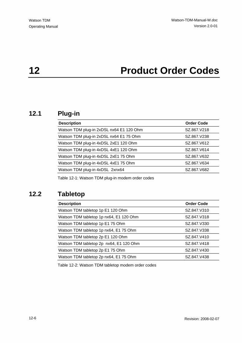
Watson TDM
Operating Manual
Watson-TDM-Manual-W.doc Version 2.0-01
12-6 Revision: 2008-02-07
12 Product Order Codes
12.1 Plug-in Description Order Code Watson TDM plug-in 2xDSL nx64 E1 120 Ohm SZ.867.V218 Watson TDM plug-in 2xDSL nx64 E1 75 Ohm SZ.867.V238 Watson TDM plug-in 4xDSL 2xE1 120 Ohm SZ.867.V612 Watson TDM plug-in 4xDSL 4xE1 120 Ohm SZ.867.V614 Watson TDM plug-in 4xDSL 2xE1 75 Ohm SZ.867.V632 Watson TDM plug-in 4xDSL 4xE1 75 Ohm SZ.867.V634 Watson TDM plug-in 4xDSL 2xnx64 SZ.867.V682
Table 12-1: Watson TDM plug-in modem order codes
12.2 Tabletop Description Order Code Watson TDM tabletop 1p E1 120 Ohm SZ.847.V310 Watson TDM tabletop 1p nx64, E1 120 Ohm SZ.847.V318 Watson TDM tabletop 1p E1 75 Ohm SZ.847.V330 Watson TDM tabletop 1p nx64, E1 75 Ohm SZ.847.V338 Watson TDM tabletop 2p E1 120 Ohm SZ.847.V410 Watson TDM tabletop 2p nx64, E1 120 Ohm SZ.847.V418 Watson TDM tabletop 2p E1 75 Ohm SZ.847.V430 Watson TDM tabletop 2p nx64, E1 75 Ohm SZ.847.V438
Table 12-2: Watson TDM tabletop modem order codes
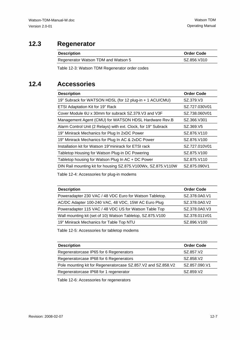
Watson-TDM-Manual-W.doc
Version 2.0-01
Watson TDM Operating Manual
Revision: 2008-02-07 12-7
12.3 Regenerator Description Order Code Regenerator Watson TDM and Watson 5 SZ.856.V310
Table 12-3: Watson TDM Regenerator order codes
12.4 Accessories Description Order Code 19" Subrack for WATSON HDSL (for 12 plug-in + 1 ACU/CMU) SZ.379.V3 ETSI Adaptation Kit for 19" Rack SZ.727.030V01 Cover Module 6U x 30mm for subrack SZ.379.V3 and V3F SZ.738.060V01 Management Agent (CMU) for WATSON HDSL Hardware Rev.B SZ.366.V301 Alarm Control Unit (2 Relays) with ext. Clock, for 19" Subrack SZ.369.V5 19" Minirack Mechanics for Plug In 2xDC Power SZ.876.V110 19" Minirack Mechanics for Plug In AC & 2xDC Power SZ.876.V100 Installation kit for Watson 19"minirack for ETSI rack SZ.727.010V01 Tabletop Housing for Watson Plug-in DC Powering SZ.875.V100 Tabletop housing for Watson Plug In AC + DC Power SZ.875.V110 DIN Rail mounting kit for housing SZ.875.V100Wx, SZ.875.V110W SZ.875.090V1
Table 12-4: Accessories for plug-in modems
Description Order Code Poweradapter 230 VAC / 48 VDC Euro for Watson Tabletop. SZ.378.0A0.V1 AC/DC Adapter 100-240 VAC, 48 VDC, 15W AC Euro Plug SZ.378.0A0.V2 Poweradapter 115 VAC / 48 VDC US for Watson Table Top SZ.378.0A0.V3 Wall mounting kit (set of 10) Watson Tabletop, SZ.875.V100 SZ.378.011V01 19" Minirack Mechanics for Table Top NTU SZ.896.V100
Table 12-5: Accessories for tabletop modems
Description Order Code Regeneratorcase IP65 for 6 Regenerators SZ.857.V2 Regeneratorcase IP68 for 6 Regenerators SZ.858.V2 Pole mounting kit for Regeneratorcase SZ.857.V2 and SZ.858.V2 SZ.857.090.V1 Regeneratorcase IP68 for 1 regenerator SZ.859.V2
Table 12-6: Accessories for regenerators
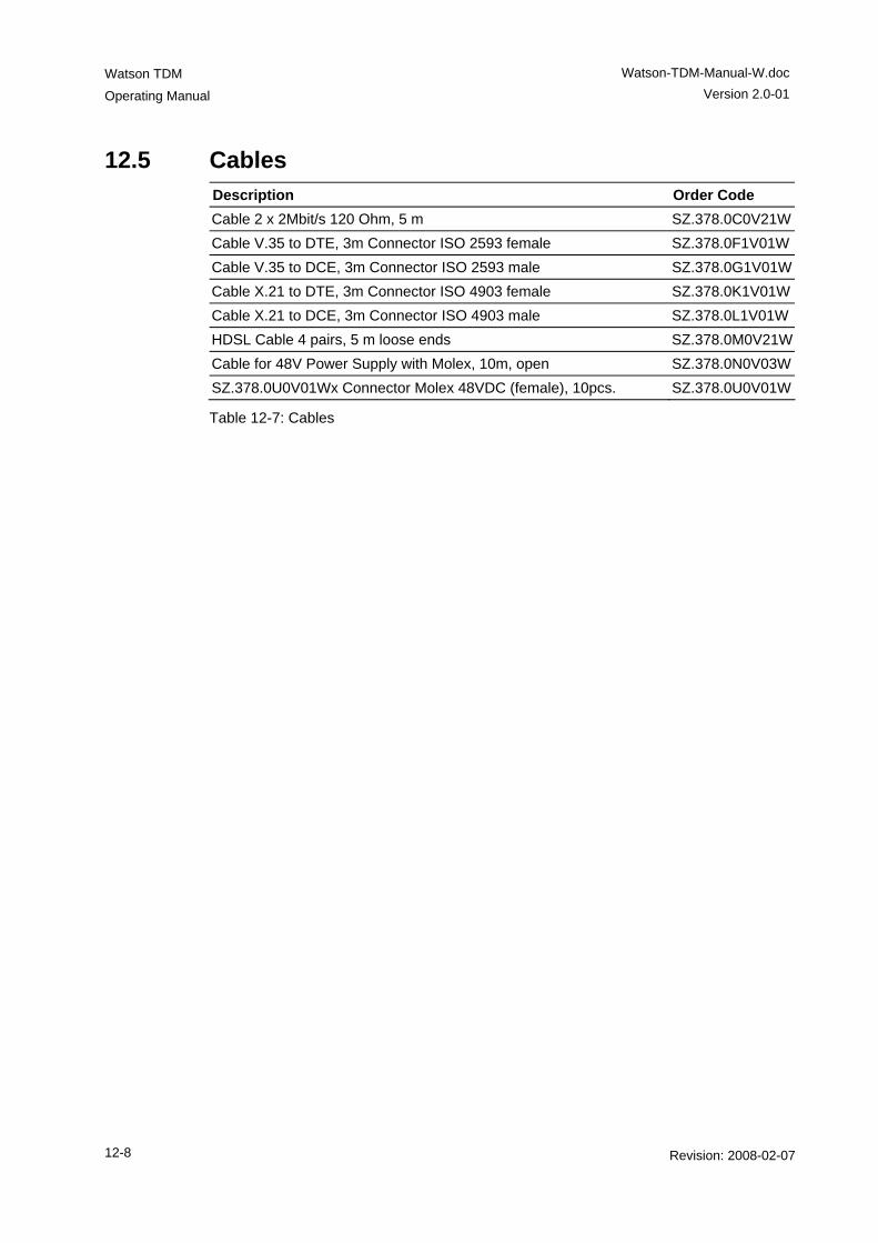
Watson TDM
Operating Manual
Watson-TDM-Manual-W.doc Version 2.0-01
12-8 Revision: 2008-02-07
12.5 Cables Description Order Code Cable 2 x 2Mbit/s 120 Ohm, 5 m SZ.378.0C0V21WCable V.35 to DTE, 3m Connector ISO 2593 female SZ.378.0F1V01WCable V.35 to DCE, 3m Connector ISO 2593 male SZ.378.0G1V01WCable X.21 to DTE, 3m Connector ISO 4903 female SZ.378.0K1V01WCable X.21 to DCE, 3m Connector ISO 4903 male SZ.378.0L1V01WHDSL Cable 4 pairs, 5 m loose ends SZ.378.0M0V21WCable for 48V Power Supply with Molex, 10m, open SZ.378.0N0V03WSZ.378.0U0V01Wx Connector Molex 48VDC (female), 10pcs. SZ.378.0U0V01W
Table 12-7: Cables