Watertightness and safety of dams using geomembranes · Today, all types of dams have a geomembrane...
15
Watertightness and safety of dams using geomembranes A M SCUERO, CARPI TECH S.A., Switzerland G L VASCHETTI, CARPI TECH S.A., Switzerland SYNOPSIS. Impervious prefabricated geomembranes are a well-established technology to provide or restore watertightness in dams. Since 1959, they have been installed on all types of dams worldwide. The paper gives an overview of how the geomembrane systems have been applied and perform on different types of dams. Some significant case histories on concrete gravity dams, masonry dams, fill dams, RCC dams are presented. INTRODUCTION Synthetic impervious geomembranes were first used on a dam in 1959. In pioneer installations, all types of geomembranes available in the market were adopted. Selection was based on local availability, on aggressiveness of marketing, on personal knowledge and information. As years went by and field results became available, selection of the geomembrane could rely also on ascertained performance. Materials that performed poorly were abandoned in favour of more flexible, robust, and durable ones. According to the ICOLD 2003 database listing 232 large dams incorporating a geomembrane for watertightness, PVC, mostly coupled to an anti-puncture geotextile, is most frequently adopted. Some other geomembranes are practically no longer used in modern applications: the last reported installation of in-situ fabricated geomembranes on a dam occurred in 1988, and of HDPE geomembranes in 1994. Pioneer installations were performed on embankment dams. In a few years, improvement in technology allowed installation on more demanding sub- vertical facings (Scuero & Vaschetti, 1998). Today, all types of dams have a geomembrane as an impervious element, either as a repair method or incorporated in the dam since original construction: these are summarised in Table 1. Long-term benefits and performance of dams. Thomas Telford, London, 2004.
-
Upload
nguyenminh -
Category
Documents
-
view
219 -
download
0
Transcript of Watertightness and safety of dams using geomembranes · Today, all types of dams have a geomembrane...
Watertightness and safety of dams using geomembranes A M SCUERO, CARPI TECH S.A., Switzerland G L VASCHETTI, CARPI TECH S.A., Switzerland SYNOPSIS. Impervious prefabricated geomembranes are a well-established technology to provide or restore watertightness in dams. Since 1959, they have been installed on all types of dams worldwide. The paper gives an overview of how the geomembrane systems have been applied and perform on different types of dams. Some significant case histories on concrete gravity dams, masonry dams, fill dams, RCC dams are presented.
INTRODUCTION Synthetic impervious geomembranes were first used on a dam in 1959. In pioneer installations, all types of geomembranes available in the market were adopted. Selection was based on local availability, on aggressiveness of marketing, on personal knowledge and information. As years went by and field results became available, selection of the geomembrane could rely also on ascertained performance. Materials that performed poorly were abandoned in favour of more flexible, robust, and durable ones. According to the ICOLD 2003 database listing 232 large dams incorporating a geomembrane for watertightness, PVC, mostly coupled to an anti-puncture geotextile, is most frequently adopted. Some other geomembranes are practically no longer used in modern applications: the last reported installation of in-situ fabricated geomembranes on a dam occurred in 1988, and of HDPE geomembranes in 1994. Pioneer installations were performed on embankment dams. In a few years, improvement in technology allowed installation on more demanding sub-vertical facings (Scuero & Vaschetti, 1998). Today, all types of dams have a geomembrane as an impervious element, either as a repair method or incorporated in the dam since original construction: these are summarised in Table 1.
Long-term benefits and performance of dams. Thomas Telford, London, 2004.
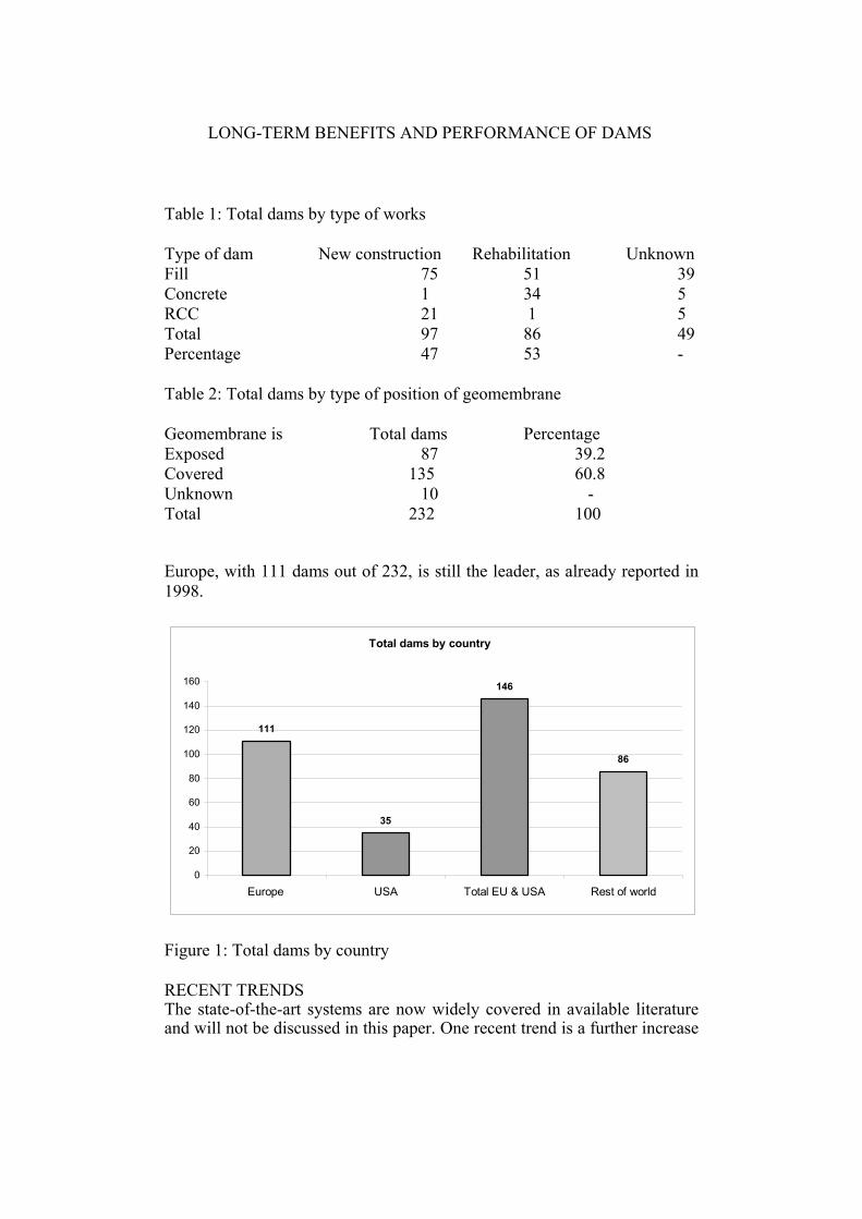
LONG-TERM BENEFITS AND PERFORMANCE OF DAMS Table 1: Total dams by type of works Type of dam New construction Rehabilitation Unknown Fill 75 51 39 Concrete 1 34 5 RCC 21 1 5 Total 97 86 49 Percentage 47 53 - Table 2: Total dams by type of position of geomembrane Geomembrane is Total dams Percentage Exposed 87 39.2 Covered 135 60.8 Unknown 10 - Total 232 100
Europe, with 111 dams out of 232, is still the leader, as already reported in 1998.
Total dams by country
111
35
146
86
0
20
40
60
80
100
120
140
160
Europe USA Total EU & USA Rest of world
Figure 1: Total dams by country RECENT TRENDS The state-of-the-art systems are now widely covered in available literature and will not be discussed in this paper. One recent trend is a further increase
SCUERO AND VASCHETTI
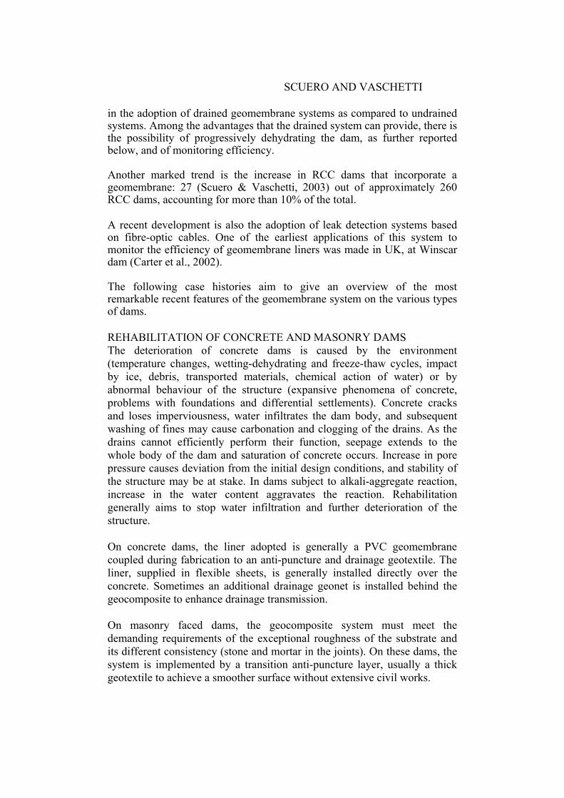
in the adoption of drained geomembrane systems as compared to undrained systems. Among the advantages that the drained system can provide, there is the possibility of progressively dehydrating the dam, as further reported below, and of monitoring efficiency. Another marked trend is the increase in RCC dams that incorporate a geomembrane: 27 (Scuero & Vaschetti, 2003) out of approximately 260 RCC dams, accounting for more than 10% of the total. A recent development is also the adoption of leak detection systems based on fibre-optic cables. One of the earliest applications of this system to monitor the efficiency of geomembrane liners was made in UK, at Winscar dam (Carter et al., 2002). The following case histories aim to give an overview of the most remarkable recent features of the geomembrane system on the various types of dams. REHABILITATION OF CONCRETE AND MASONRY DAMS The deterioration of concrete dams is caused by the environment (temperature changes, wetting-dehydrating and freeze-thaw cycles, impact by ice, debris, transported materials, chemical action of water) or by abnormal behaviour of the structure (expansive phenomena of concrete, problems with foundations and differential settlements). Concrete cracks and loses imperviousness, water infiltrates the dam body, and subsequent washing of fines may cause carbonation and clogging of the drains. As the drains cannot efficiently perform their function, seepage extends to the whole body of the dam and saturation of concrete occurs. Increase in pore pressure causes deviation from the initial design conditions, and stability of the structure may be at stake. In dams subject to alkali-aggregate reaction, increase in the water content aggravates the reaction. Rehabilitation generally aims to stop water infiltration and further deterioration of the structure. On concrete dams, the liner adopted is generally a PVC geomembrane coupled during fabrication to an anti-puncture and drainage geotextile. The liner, supplied in flexible sheets, is generally installed directly over the concrete. Sometimes an additional drainage geonet is installed behind the geocomposite to enhance drainage transmission. On masonry faced dams, the geocomposite system must meet the demanding requirements of the exceptional roughness of the substrate and its different consistency (stone and mortar in the joints). On these dams, the system is implemented by a transition anti-puncture layer, usually a thick geotextile to achieve a smoother surface without extensive civil works.
LONG-TERM BENEFITS AND PERFORMANCE OF DAMS
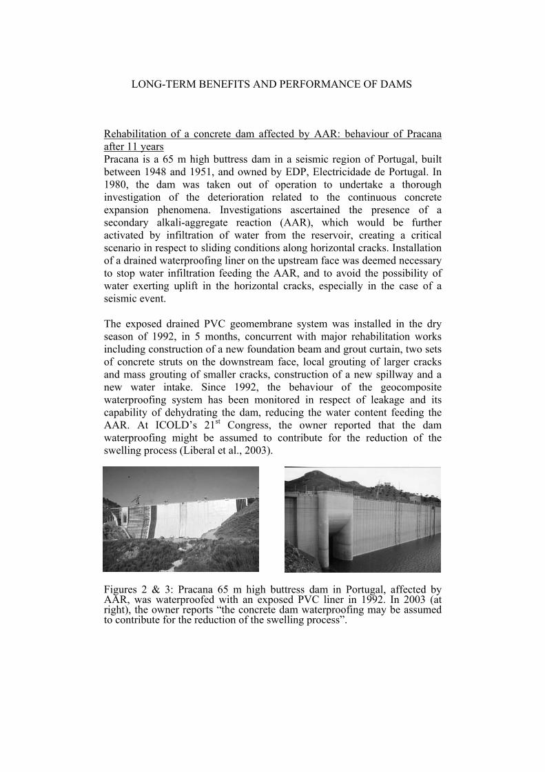
Rehabilitation of a concrete dam affected by AAR: behaviour of Pracana after 11 years Pracana is a 65 m high buttress dam in a seismic region of Portugal, built between 1948 and 1951, and owned by EDP, Electricidade de Portugal. In 1980, the dam was taken out of operation to undertake a thorough investigation of the deterioration related to the continuous concrete expansion phenomena. Investigations ascertained the presence of a secondary alkali-aggregate reaction (AAR), which would be further activated by infiltration of water from the reservoir, creating a critical scenario in respect to sliding conditions along horizontal cracks. Installation of a drained waterproofing liner on the upstream face was deemed necessary to stop water infiltration feeding the AAR, and to avoid the possibility of water exerting uplift in the horizontal cracks, especially in the case of a seismic event. The exposed drained PVC geomembrane system was installed in the dry season of 1992, in 5 months, concurrent with major rehabilitation works including construction of a new foundation beam and grout curtain, two sets of concrete struts on the downstream face, local grouting of larger cracks and mass grouting of smaller cracks, construction of a new spillway and a new water intake. Since 1992, the behaviour of the geocomposite waterproofing system has been monitored in respect of leakage and its capability of dehydrating the dam, reducing the water content feeding the AAR. At ICOLD’s 21st Congress, the owner reported that the dam waterproofing might be assumed to contribute for the reduction of the swelling process (Liberal et al., 2003).
Figures 2 & 3: Pracana 65 m high buttress dam in Portugal, affected by AAR, was waterproofed with an exposed PVC liner in 1992. In 2003 (at right), the owner reports “the concrete dam waterproofing may be assumed to contribute for the reduction of the swelling process”.
SCUERO AND VASCHETTI
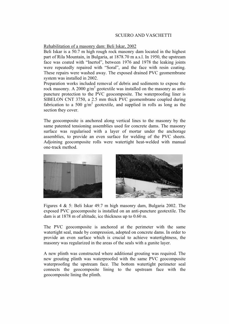
Rehabilitation of a masonry dam: Beli Iskar, 2002 Beli Iskar is a 50.7 m high rough rock masonry dam located in the highest part of Rila Mountain, in Bulgaria, at 1878.70 m a.s.l. In 1950, the upstream face was coated with “Inertol”, between 1976 and 1978 the leaking joints were repeatedly repaired with “Soral”, and the face with resin coating. These repairs were washed away. The exposed drained PVC geomembrane system was installed in 2002. Preparation works included removal of debris and sediments to expose the rock masonry. A 2000 g/m2 geotextile was installed on the masonry as anti-puncture protection to the PVC geocomposite. The waterproofing liner is SIBELON CNT 3750, a 2.5 mm thick PVC geomembrane coupled during fabrication to a 500 g/m2 geotextile, and supplied in rolls as long as the section they cover. The geocomposite is anchored along vertical lines to the masonry by the same patented tensioning assemblies used for concrete dams. The masonry surface was regularised with a layer of mortar under the anchorage assemblies, to provide an even surface for welding of the PVC sheets. Adjoining geocomposite rolls were watertight heat-welded with manual one-track method. Figures 4 & 5: Beli Iskar 49.7 m high masonry dam, Bulgaria 2002. The exposed PVC geocomposite is installed on an anti-puncture geotextile. The dam is at 1878 m of altitude, ice thickness up to 0.60 m. The PVC geocomposite is anchored at the perimeter with the same watertight seal, made by compression, adopted on concrete dams. In order to provide an even surface which is crucial to achieve watertightness, the masonry was regularized in the areas of the seals with a gunite layer. A new plinth was constructed where additional grouting was required. The new grouting plinth was waterproofed with the same PVC geocomposite waterproofing the upstream face. The bottom watertight perimeter seal connects the geocomposite lining to the upstream face with the geocomposite lining the plinth.
LONG-TERM BENEFITS AND PERFORMANCE OF DAMS EMBANKMENT DAMS In embankment dams, watertightness must be provided by a material different from the materials constituting the dam body. Traditionally, the barrier to water infiltration had been made with either natural or man-made materials, by constructing either an impervious core using materials such as asphaltic concrete or clay, or an impervious upstream face as in Concrete Faced Rockfill Dams (CFRD) and embankment dams with an asphalt concrete upstream layer. The use of traditional materials such as clay or asphaltic concrete requires adequate materials selection, placing and compaction. Sometimes appropriate materials are not available at reasonable costs, or available materials do not have the required quality, or construction is difficult, time consuming and expensive. Sometimes inadequate construction, or inadequate weathering resistance, for example with some asphaltic concrete facings, leads to increasing leakage over time. The final result may end up with general poor performance of the dam. CFRDs in turn involve complicated design, and construction of the face slab and of its complex waterstop system can significantly affect the overall construction time. Time schedules have often been extended considerably beyond what was initially foreseen, especially when contractors have had no previous experience with this type of construction. From a performance perspective, although installation of the concrete layer occurs when placing of the fill has been completed and the anticipated major settlements have taken place, in many CFRD’s already built the settlement of the fill continued after the filling of the reservoir. There are dams where the deformation due to the settlement, combined with the deformation of the fill due to the hydraulic head, provoked cracks in the concrete face and/or failure of the waterstop systems. This problem, related to the placement of a rigid element (the waterproofing concrete face) over the deformable fill dam body, is aggravated in dams constructed in seismic areas. In new construction, the use of synthetic impervious geomembranes avoids the problems connected with design and installation of multiple defence lines of waterstops, with deterioration of waterstops, with connections of the core or of the asphalt concrete to concrete structures. In case suitable traditional materials are not available at reasonable cost, the geomembrane option can make the project feasible. In new construction as well as rehabilitation, the geomembrane can maintain watertightness in the presence of relative movements of the dam and of differential settlements of the fill. With very few exceptions, mostly in Chinese dams, the PVC geomembrane is installed in the upstream position. This is technically preferred as it

SCUERO AND VASCHETTI
minimises uncontrolled water presence in the dam body, improving safety. Exposed upstream membrane systems also allow easy inspection, and have lower construction times and costs. Specific aspects to be addressed for rehabilitation of embankment dams are the face and perimeter anchorage systems, which are designed depending on the type and strength of the existing facing (asphaltic concrete or concrete). An outstanding example of rehabilitation of asphaltic concrete facing has been Winscar dam in UK. The following case history addresses a recent repair of CFRD.
Rehabilitation of embankment dams: Strawberry CFRD, 2002 Strawberry, the second oldest concrete faced rockfill dam in the world, is located in the USA. Owned by Pacific Gas and Electric Co. (PG&E), the dam is 43 m high and about 220 m long, and has 9 vertical joints that did not have any waterstops installed. Deterioration of joints caused increasing leakage that over the years became unacceptable to California dam safety officials. To permanently reduce leakage, PG&E selected for Strawberry an external waterstop system that was a development of the concept adopted for exposed geomembrane systems on entire face dams since 1976. The exposed waterstop system, which is patented, consists of a PVC geocomposite installed at the joints over a support layer. The waterproofing liner intrudes in the active joint at maximum opening of joint under the maximum water head. The geocomposite is watertight anchored along the perimeter and is left exposed to the water of the reservoir. Differently from conventional embedded waterstops, which allow deformation only of few millimetres in the central portion of the bulb, the external waterstop can deform along the entire width of the PVC geocomposite (typically 40 to 60 cm), hence it is capable of accommodating significant movements that may occur in the joint. The system is the same installed to waterproof the contraction joints of RCC dams (see below). At Strawberry the external waterstop, patented, consisted of four layers. The first two layers, Layers 1 and 2, anchored along edges on both sides by impact anchors into the existing sound concrete or in new shotcrete which replaced excessively damaged concrete, were a geocomposite made by a polyvinyl chloride (PVC) membrane 2.5 mm thick with a 500 g/m2 geotextile laminated to it. These first two layers acted as anti-intrusion support on the joints, and were anchored so that they could move independently of each other. Layer No. 3 was a non-woven geotextile anchored along its vertical edges. This layer had an anti-friction purpose, to
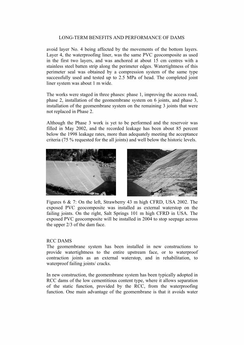
LONG-TERM BENEFITS AND PERFORMANCE OF DAMS avoid layer No. 4 being affected by the movements of the bottom layers. Layer 4, the waterproofing liner, was the same PVC geocomposite as used in the first two layers, and was anchored at about 15 cm centres with a stainless steel batten strip along the perimeter edges. Watertightness of this perimeter seal was obtained by a compression system of the same type successfully used and tested up to 2.5 MPa of head. The completed joint liner system was about 1 m wide. The works were staged in three phases: phase 1, improving the access road, phase 2, installation of the geomembrane system on 6 joints, and phase 3, installation of the geomembrane system on the remaining 3 joints that were not replaced in Phase 2. Although the Phase 3 work is yet to be performed and the reservoir was filled in May 2002, and the recorded leakage has been about 85 percent below the 1998 leakage rates, more than adequately meeting the acceptance criteria (75 % requested for the all joints) and well below the historic levels. Figures 6 & 7: On the left, Strawberry 43 m high CFRD, USA 2002. The exposed PVC geocomposite was installed as external waterstop on the failing joints. On the right, Salt Springs 101 m high CFRD in USA. The exposed PVC geocomposite will be installed in 2004 to stop seepage across the upper 2/3 of the dam face.
RCC DAMS The geomembrane system has been installed in new constructions to provide watertightness to the entire upstream face, or to waterproof contraction joints as an external waterstop, and in rehabilitation, to waterproof failing joints/ cracks. In new construction, the geomembrane system has been typically adopted in RCC dams of the low cementitious content type, where it allows separation of the static function, provided by the RCC, from the waterproofing function. One main advantage of the geomembrane is that it avoids water
SCUERO AND VASCHETTI
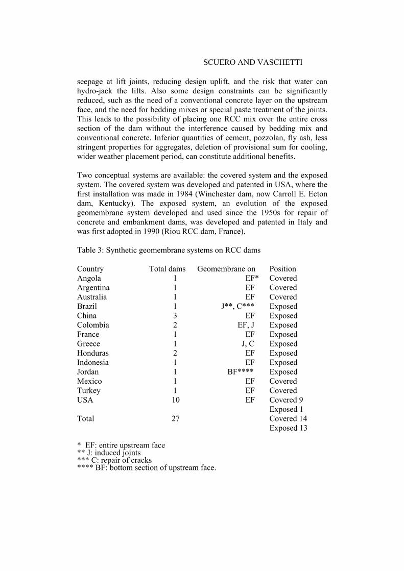
seepage at lift joints, reducing design uplift, and the risk that water can hydro-jack the lifts. Also some design constraints can be significantly reduced, such as the need of a conventional concrete layer on the upstream face, and the need for bedding mixes or special paste treatment of the joints. This leads to the possibility of placing one RCC mix over the entire cross section of the dam without the interference caused by bedding mix and conventional concrete. Inferior quantities of cement, pozzolan, fly ash, less stringent properties for aggregates, deletion of provisional sum for cooling, wider weather placement period, can constitute additional benefits. Two conceptual systems are available: the covered system and the exposed system. The covered system was developed and patented in USA, where the first installation was made in 1984 (Winchester dam, now Carroll E. Ecton dam, Kentucky). The exposed system, an evolution of the exposed geomembrane system developed and used since the 1950s for repair of concrete and embankment dams, was developed and patented in Italy and was first adopted in 1990 (Riou RCC dam, France). Table 3: Synthetic geomembrane systems on RCC dams Country Total dams Geomembrane on Position Angola 1 EF* Covered Argentina 1 EF Covered Australia 1 EF Covered Brazil 1 J**, C*** Exposed China 3 EF Exposed Colombia 2 EF, J Exposed France 1 EF Exposed Greece 1 J, C Exposed Honduras 2 EF Exposed Indonesia 1 EF Exposed Jordan 1 BF**** Exposed Mexico 1 EF Covered Turkey 1 EF Covered USA 10 EF Covered 9 Exposed 1 Total 27 Covered 14 Exposed 13 * EF: entire upstream face ** J: induced joints *** C: repair of cracks **** BF: bottom section of upstream face.
LONG-TERM BENEFITS AND PERFORMANCE OF DAMS New construction: Miel I, Colombia 2002, and Olivenhain, 2003 Miel I is a straight gravity dam constructed in a narrow gorge in Colombia. At 188 m, it is the world’s highest RCC dam. The dam crest, at an elevation of 454 m, is 354 m long and the entire upstream face is 31,500 m2. To meet the contractual schedule, the original design of an upstream face made of slip formed reinforced concrete was changed to a drained exposed PVC geomembrane system, placed on a 0.4 m wide zone of grout enriched vibrated RCC. Due to the height of the exposed dam face, this double protection was considered necessary (Marulanda et al. 2002). The use of grout enriched RCC allowed applying good compaction of RCC mix at the dam face, assuring a good finishing of the upstream concrete surface. The RCC mix has a cement content of 85 to 160 kg/m3; total RCC volume is 1,745,000 m3. Contraction joints are placed every 18.5 m. The waterproofing liner is a composite geomembrane, consisting of PVC geomembrane laminated to a 500 g/m2 polypropylene nonwoven geotextile. In the deepest 62 m the PVC geomembrane is 3 mm thick, in the top 120 m it is 2.5 mm thick. The PVC geocomposite was installed over the upstream surface, after removal of the formwork. At the contraction joints, two layers of sacrificial geocomposite, of the same type used for the waterproofing liner, provide support-avoiding intrusion of the liner in the active joint. The attachment system for the PVC geocomposite on the dam face is made by parallel lines of tensioning profiles assemblies, placed at 3.70 m spacing. Where the water head is higher, from elevation 268 m to 358 m, the stainless steel profiles have a central reinforcement. A seal watertight against water in pressure up to 240 m fastens the PVC geocomposite along all peripheries. The drainage system, consisting of the geotextile attached to the PVC geomembrane, of the vertical conduits made by the tensioning assemblies, of longitudinal collectors and of transverse discharge pipes, is divided into 4 horizontal sections (compartments). Each horizontal compartment is in turn divided into vertical sections with a separate discharge. Each compartment discharges in the gallery located at its bottom. In total there are 45 separate compartments, achieving very accurate monitoring of the behaviour of the waterproofing system. To allow installation of the PVC waterproofing system to take place independently of the RCC activities, a railing system was attached to the dam face at a first level of 360 m, approximately 90 m above foundation, and then moved to a second level of 407 m, some 140 m above foundation.
SCUERO AND VASCHETTI
The change in design allowed the schedule to be met. Construction of the dam started in April 2000 and ended in June 2002, for a total of 26 months. Olivenhain is an RCC gravity dam 788 m long and 97 m high completed in summer 2003 in California. It is the highest and largest RCC dam in USA. The dam is a key element of the Emergency Storage Project (ESP) of the San Diego County Water Authority, owner of the dam. About 90% of water is brought to San Diego from hundreds of miles away, and the aqueducts cross several large active faults, including the San Andreas fault. The ESP is a multi year program that will provide water to the San Diego region in case of an interruption in water delivery deriving from an earthquake or drought, thus allowing time to repair the aqueduct. The geomembrane system was selected because it was deemed that, following a seismic event, it would have been able to prevent seepage losses through any resulting cracks (Kline et al., 2002). Furthermore, the geomembrane liner and its associated face drainage system were considered to be two features that would tend to reduce the uplift pressure. The waterproofing system is conceptually the same adopted at Miel I. The PVC geomembrane is 2.5 mm thick, and the drainage system differs in that the number of compartments is lower, and there is an additional drainage geonet over the entire upstream face.
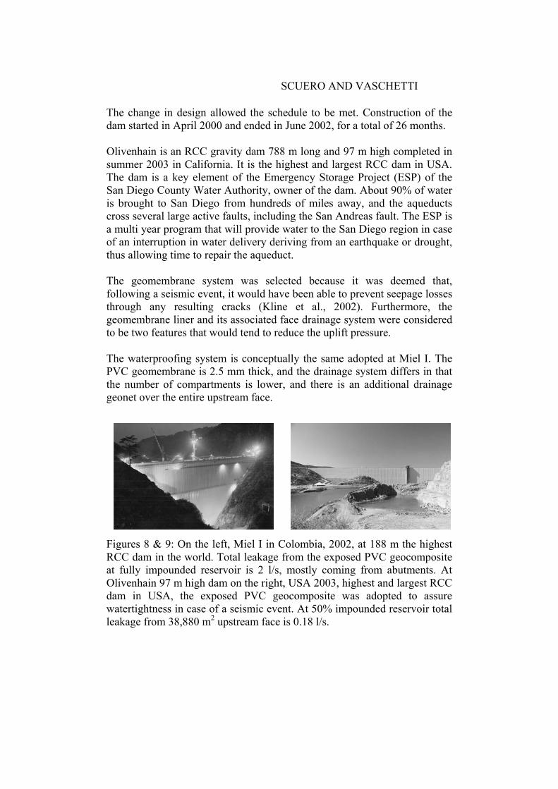
Figures 8 & 9: On the left, Miel I in Colombia, 2002, at 188 m the highest RCC dam in the world. Total leakage from the exposed PVC geocomposite at fully impounded reservoir is 2 l/s, mostly coming from abutments. At Olivenhain 97 m high dam on the right, USA 2003, highest and largest RCC dam in USA, the exposed PVC geocomposite was adopted to assure watertightness in case of a seismic event. At 50% impounded reservoir total leakage from 38,880 m2 upstream face is 0.18 l/s.
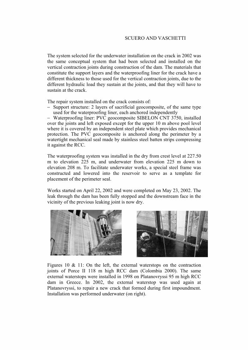
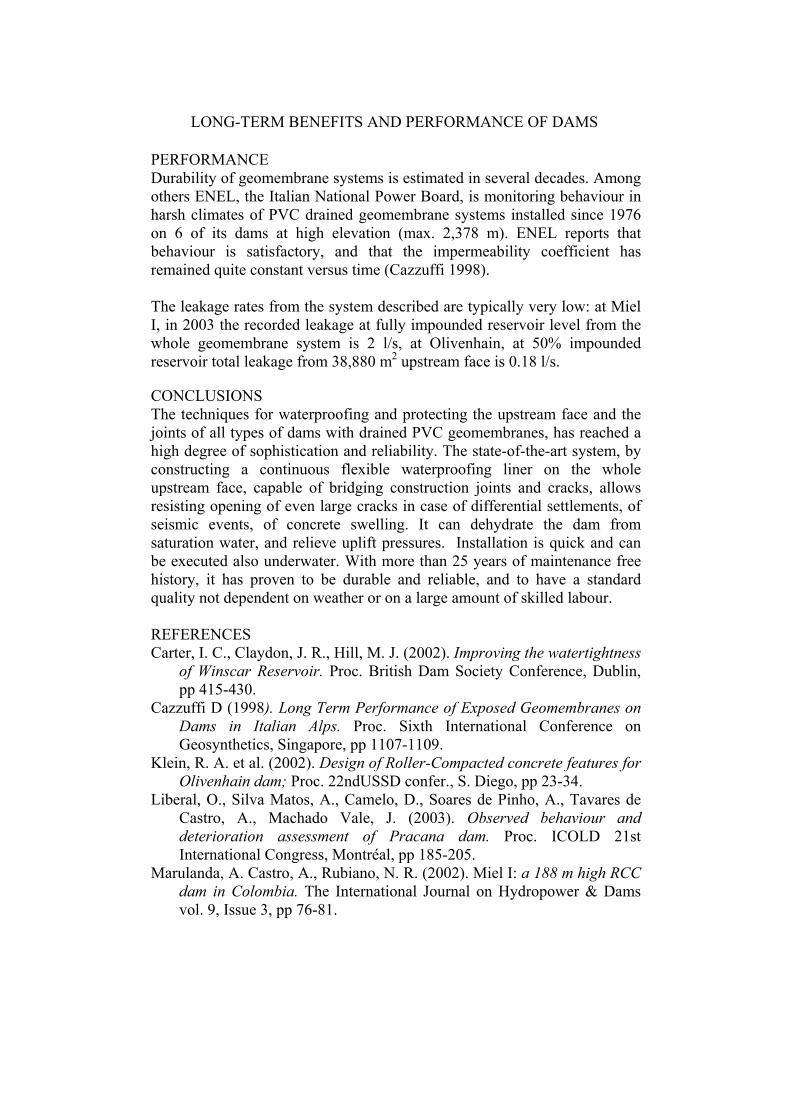
LONG-TERM BENEFITS AND PERFORMANCE OF DAMS Exposed waterstop: Porce II, Colombia 2000 Porce II is a 118 m high RCC dam constructed in 2000 in Colombia. Its upstream face is formed by curb extruder. The contraction joints, at average spacing of 35 m, are waterproofed with a patented external waterstop system. In detail, at Porce II the system consists of: − Support structure: proceeding from the dam body towards the reservoir,
support is made by two stainless steel plates having a strip of Teflon in-between to decrease friction and allow sliding of the plates, of one 2,000 g/m² polyester geotextile providing anti-puncture protection against the sliding edges of the steel plates, and of one sacrifice/supporting PVC geocomposite. The steel support impedes intrusion of the waterproofing liner into the active joint, and the flexible components provide extra support and a low friction element, so that the movements of the joint occur without affecting the waterproofing geocomposite
− Waterproofing liner: a PVC geocomposite, SIBELON CNT 5050, consisting of a 3.5 mm thick PVC geomembrane heat-coupled during extrusion to a 500 g/m2 polyester geotextile. The geocomposite is exposed and centred on the joint and watertight anchored at the periphery by flat stainless steel batten strips compressing it against the concrete, regularised by trimming the offsets and by a layer of epoxy resin. Synthetic gaskets distribute stress to achieve even compression. At plinth, the PVC geocomposite is connected directly against the rock.
Rehabilitation: Platanovryssi, 2002 The external waterstop system has been used for the underwater repair of Platanovryssi, a 95 m high RCC dam in Greece. Platanovryssi was completed in 1998 and is at present the highest RCC dam in Europe. The dam, of the high cementitious content type, was designed to be impermeable in its whole RCC mass. The vertical contraction joints were waterproofed with 12 Carpi external waterstop system during construction. On first filling, after mid-December 1999, seepage started increasing, and reached more than 21 l/s at the end of May, dropped again and then increased to a maximum of 30.56 l/s on 10 October 2000. The cause of the leak was what appeared at first as a hairline crack in the gallery, then on the upstream and downstream face, with a maximum opening of 25 mm. The crack was approximately 20 m long. Repair works were scheduled for Spring 2002. Due to an unusually dry season, the owner could not afford to lose the volume of the water to empty the reservoir in order to work in dry conditions. In addition to that restriction, when Platanovryssi is emptied the pumped storage scheme of Thissavros cannot operate, with serious implications to the production system. It was considerably more cost effective to do the work underwater (Papadopoulos 2002).
SCUERO AND VASCHETTI
The system selected for the underwater installation on the crack in 2002 was the same conceptual system that had been selected and installed on the vertical contraction joints during construction of the dam. The materials that constitute the support layers and the waterproofing liner for the crack have a different thickness to those used for the vertical contraction joints, due to the different hydraulic load they sustain at the joints, and that they will have to sustain at the crack. The repair system installed on the crack consists of: − Support structure: 2 layers of sacrificial geocomposite, of the same type
used for the waterproofing liner, each anchored independently − Waterproofing liner: PVC geocomposite SIBELON CNT 3750, installed over the joints and left exposed except for the upper 10 m above pool level where it is covered by an independent steel plate which provides mechanical protection. The PVC geocomposite is anchored along the perimeter by a watertight mechanical seal made by stainless steel batten strips compressing it against the RCC. The waterproofing system was installed in the dry from crest level at 227.50 m to elevation 225 m, and underwater from elevation 225 m down to elevation 208 m. To facilitate underwater works, a special steel frame was constructed and lowered into the reservoir to serve as a template for placement of the perimeter seal. Works started on April 22, 2002 and were completed on May 23, 2002. The leak through the dam has been fully stopped and the downstream face in the vicinity of the previous leaking joint is now dry. Figures 10 & 11: On the left, the external waterstops on the contraction joints of Porce II 118 m high RCC dam (Colombia 2000). The same external waterstops were installed in 1998 on Platanovryssi 95 m high RCC dam in Greece. In 2002, the external waterstop was used again at Platanovryssi, to repair a new crack that formed during first impoundment. Installation was performed underwater (on right).
LONG-TERM BENEFITS AND PERFORMANCE OF DAMS PERFORMANCE Durability of geomembrane systems is estimated in several decades. Among others ENEL, the Italian National Power Board, is monitoring behaviour in harsh climates of PVC drained geomembrane systems installed since 1976 on 6 of its dams at high elevation (max. 2,378 m). ENEL reports that behaviour is satisfactory, and that the impermeability coefficient has remained quite constant versus time (Cazzuffi 1998). The leakage rates from the system described are typically very low: at Miel I, in 2003 the recorded leakage at fully impounded reservoir level from the whole geomembrane system is 2 l/s, at Olivenhain, at 50% impounded reservoir total leakage from 38,880 m2 upstream face is 0.18 l/s.
CONCLUSIONS The techniques for waterproofing and protecting the upstream face and the joints of all types of dams with drained PVC geomembranes, has reached a high degree of sophistication and reliability. The state-of-the-art system, by constructing a continuous flexible waterproofing liner on the whole upstream face, capable of bridging construction joints and cracks, allows resisting opening of even large cracks in case of differential settlements, of seismic events, of concrete swelling. It can dehydrate the dam from saturation water, and relieve uplift pressures. Installation is quick and can be executed also underwater. With more than 25 years of maintenance free history, it has proven to be durable and reliable, and to have a standard quality not dependent on weather or on a large amount of skilled labour. REFERENCES Carter, I. C., Claydon, J. R., Hill, M. J. (2002). Improving the watertightness
of Winscar Reservoir. Proc. British Dam Society Conference, Dublin, pp 415-430.
Cazzuffi D (1998). Long Term Performance of Exposed Geomembranes on Dams in Italian Alps. Proc. Sixth International Conference on Geosynthetics, Singapore, pp 1107-1109.
Klein, R. A. et al. (2002). Design of Roller-Compacted concrete features for Olivenhain dam; Proc. 22ndUSSD confer., S. Diego, pp 23-34.
Liberal, O., Silva Matos, A., Camelo, D., Soares de Pinho, A., Tavares de Castro, A., Machado Vale, J. (2003). Observed behaviour and deterioration assessment of Pracana dam. Proc. ICOLD 21st International Congress, Montréal, pp 185-205.
Marulanda, A. Castro, A., Rubiano, N. R. (2002). Miel I: a 188 m high RCC dam in Colombia. The International Journal on Hydropower & Dams vol. 9, Issue 3, pp 76-81.
SCUERO AND VASCHETTI
Papadopoulos, D. (2002). Seepage evolution and underwater repairs at Platanovryssi. The International Journal on Hydropower & Dams vol. 9, Issue 6, pp 88-90.
Scuero A M, Vaschetti G L (1998). A drained synthetic geomembrane system for rehabilitation and construction of dams. Proc. British Dam Society Conference, Bangor, pp 359-372.
Scuero A M, Vaschetti G L (2003). Synthetic geomembranes in RCC dams: since 1984, a reliable cost effective way to stop leakage. Proc. 4th International Symposium on Roller Compacted Concrete (RCC) Dams, Madrid, pp 519-529.