Water treatment technology using MU Static Spiral ...
Water treatment technology using MU Static Spiral Perforated Wings (MU-SSPW)™ -A path from horizontal to vertical type of water treatment device- Hisao KOJIMA *1 , Terutoshi SUZUKI *2 , Yoshiaki ITO *3 , Jun IKEDA *4 , Tadamine MAKI *5 MU Company Ltd. Technical partnership with MU USA Corporation © 2018 MU Co., Ltd.
Transcript of Water treatment technology using MU Static Spiral ...
Water treatment technology using MU Static Spiral Perforated Wings (MU-SSPW)™ -A path from horizontal to vertical type of water treatment device-
Hisao KOJIMA*1, Terutoshi SUZUKI*2, Yoshiaki ITO*3, Jun IKEDA*4, Tadamine MAKI*5
MU Company Ltd.Technical partnership with MU USA Corporation
© 2018 MU Co., Ltd.

2.1 Aeration in aeration tank
The fi rst example is an improved treatment for exhaust
water in aeration tank. Aeration in tank is performed by
many methods as shown in Fig. 1. But these disadvantages
are:
1. Frequent failure by the dirtiness and clogging of devices
2. A need of regular cleaning to avoid generating toxic
gases, such as H2S, NH3 and CH4, due to polluted sludge
deposited on the base of a tank.
3. Low effectiveness of the utilization of oxygen
4. Lack of durability
(Improved Example)
A plant had two sets of aeration tanks with each volume
of 4,300m3, aerated by a surface type of aeration, but had
been long suffered from the generation of odor and fl ying
mist. The tanks had been cleaned up once every two years.
However, since the plant quitted the surface aeration and
started to use one of our products, MU Aerator (MA-
125 type), the product has successfully reduced the odor
drastically and stopped generating the fl ying mist and toxic
gases. The device also made the tanks free of maintenance,
1. Introduction1.1 Environment surrounding water resource
Today, with the worldwide development of the economy
and its successive increase of population, the demand
for water is accelerating. Under this circumstance, water
pollution in some regions is getting critical due to the
remarkable industrialization and urbanization propelled
by the development of the economy. The pollution now
becomes a social problem. Water is an essential foundation
of our lives and it is inevitable for us to keep the water
environment in good condition.
In the light of the condition, technologies of water
treatment are getting more critical. Now a variety of devices
for water treatment have been developed, and among them,
our products are featured by saving-space, high effi ciency,
and maintenance-free, with the principles different from the
conventional devices. This paper introduces our products
for water treatment, then the principle of MU-SSPW (MU
Static Spiral Performed Wings), the core technology of
our devices, and fi nally proposes the vertical type of water
treatment product, entirely different from the conventional
horizontal type of water treatment. It would be appreciated
if the paper causes a small ripple on the industry of water
treatment.
1.2 Construct of the paper
First, chapter 2 introduces various usages of our products
in water treatment. Chapter 3 explains the principles of our
products, inspired by the laws of nature, and the features,
such as saving-space, high effi ciency and maintenance-free,
of our vertical devices. Chapter 4 describes our vertical
products, MU Aqua Tower and MU Floating Tower, applied
in a closed water area, such as pond and lake. And chapter
5 concludes the paper.
2. Main examples of exhaust gas and water treatment of our products First, chapter 2 introduces various usages of our products
in water treatment. Chapter 3 explains the principles of our
products, inspired by the laws of nature, and the features,
such as saving-space, high effi ciency and maintenance-free,
of our vertical devices. Chapter 4 describes our vertical
products, MU Aqua Tower and MU Floating Tower, applied
in a closed water area, such as pond and lake. And chapter
5 concludes the paper.
Air(1) Aeration by air nozzle-Air nozzle just by holes on pipe or with spray nozzle
(2) Rotation type-Agitate by feeding air into rorating turbine disk
(3) Filter module type-Blow air from fine pores of filter
(4) Surface aeration type-Contact water with air by sprinkling water using hung-up pump
-Blow air from rorating drum
Air
Air
Air
Fig. 1 Conventional Aeration Method
1

which reduces the cost of maintenance drastically and cut
the cost of electric power by 24%.
2.2 Degassing treatment of wastewater
The next examples of MU-SSPW are some applications
of effective degassing treatment in wastewater. We have
provided more than 30 sets of MU Scrubber for 35 years
since the foundation of our company. The product tends
to be repeatedly ordered by the same customers. Now we
explain four main examples of the application: removal of
chlorine organic compound in wastewater, degassing of
brine water, CO2 removal in seawater, and NH3 stripping
removal in wastewater.
2.2.1 Removal of chlorine organic compound in wastewater
This example clearly shows a significant effect of one
of the features of MU-SSPW, self-purification (Fig. 2).
The objective of this unit is to remove chlorine organic
compound contained in process wastewater by stripping
with the use of sieve tray in a tower. This wastewater
includes calcium-based substance and the substance is
easy to extract, so the tower should have been stopped to
clean up once every four months. Reboiler couldn’t be
used because of the easiness of clogging, so steam should
be sent to the bottom of the tower directly. The exhaust
water includes 300 wet ppm of chlorine organic compound
and more than 90 % of the compound is reused in the
process after stripping to the top of the tower to collect the
substance. The tower has a diameter of 2.8 meters and eight
layers of sieve tray, performing vacuum steam distillation.
As it is getting dirty on the part of downcomer of sieve tray
inside the tower, the rate of removal of chlorine organic
compound is getting worse. To make up for the lowered
efficiency of removal, the rate of reflux should be increased
and the volume of wastewater be decreased. In spite of such
measures, the operation is getting discontinued and should
be stopped to open up the tower for cleaning. The series of
actions had been repeated.
Changing sieve tray into MU-SSPW element can solve
the first problem, the dirtiness and clogging inside the
tower. The elements succeed in keeping the long-term
operation without any interruption. Even ten years later
from this improvement, the rate of removal of chlorine
organic compound keeps more than 95% and the tower
can be operated with a stable low differential pressure. The
saving of energy and maintenance cost and the increase of
reuse of chlorine organic compound result in a synergetic
effect.
2.2.2 Degassing of brine water
This is an example of the application of MU-SSPW to
a device for degassing CO2 and O2 in the brine, including
20% wet of NaCl, under the condition of vacuum (Fig. 3).
Under the severe condition, MU-SSPW is highly acclaimed
by the customer for no clogging and its long-term stable
operation (Photo 1, 2). The changing material of the device
from corrosion-resistant metal into FRP would achieve the Conventional
Conventional2.8mDiameter
Removal Rate
Volume of Steam
Total Differential Pressure
Time for Continuous Run
Drainage Volume
Concentration of chlorine organic compound in treated water
1.5m
600t/h400-600t/h
4t/h12t/h
≧ 10yrs4 months
≦10wt ppm20-30wt ppm
≧ 95%90%
≦ 150mmH2O700mmH2O
Drainage
Steam
Drainage
Steam
Treatment Water
Treatment Water
Reuse
Reuse
MU
MU
Fig. 2 Improved example of removal of chlorine organic compound
Conventional degassing column
MU degassing column
Photo 1 Comparison between conventional and MU degassing tower
Photo 2 MU-SSPW element
Brine
Vacuumdevice
Treatment Water
Fig. 3 Example of degassing of brine
2

long-lasting durability, which contributes to the reduction
of initial investment.
2.2.3 Removal of CO2 in sea water
This example is an operational improvement of making
air remove 100ppm of CO2 dissolved in the exhaust
seawater (Fig. 4). This operation needs big equipment
and a large volume of air. However, the facility needed a
large amount of maintenance cost because the packings
were clogged by salt and the facility needed to be halted
for cleaning. So, to tackle these problems, the following
measures should be taken:
1. Change the packings into MU-SSPW element.
2. Add MU-MIXER into the feed line of sea water to ensure
the pH adjustment.
Because salt makes the facility getting more dirt and
clogged, the equipment needs to be bigger, which lowers
the rate of gas-liquid contact. To keep the function of the
equipment, the deterioration needs more air, which falls in
a vicious circle.
By introducing MU-SSPW, the equipment can be kept
clean, which breaks a negative circle. Downsizing results
in the reduction of the volume of air absorption, leading to
energy saving and the long-term stable operation.
2.2.4 Removal of NH3 in wastewater by stripping
MU-SSPW element is applied to a tower stripping
NH3 contained in wastewater into air (Fig. 5). The whole
volume of the tower is very compact since the flow of gas
and liquid is countercurrent and the speed of gas inside
the tower can be 2 to 4 m/s as design value. Air can be
replaced with steam stripping, which achieves more than 90
% of the removal rate of NH3 and less than 200 mmH2O of
differential pressure inside the tower.
2.3 Removal of ethanol in the exhaust gas
This is a countercurrent absorption tower to change
7,000 volume ppm of ethanol in exhaust gas into less than
100 volume ppm of ethanol in it by absorbing ethanol in
water. By using MU-SSPW, more than 98.5% of removal
of ethanol can be achieved (Fig. 6). 3 m/s of gas speed
will be within an area of flooding in the other conventional
packing columns. Since the start of operation, years of safe
operation of our products have continued. Fig 6 shows the
specification of the tower.
Conventional MU
Conventional
Size of Tower
Packing
Material of Tower CS + Resin Lining
Resin
200mmH2O
60% Down
60% Down
50% Down
≦100mmH2O
Material of Internal
MU
Chemical
Seawater
Air Air
Seawater
Chemical
Irregular Packings
Next Stage Next Stage
Total Differential Pressure
Volume of Air
Volume of Power
Volume of Chemical
Cleaning Once a year No cleaning in more than 5 yrs
Fig. 4 Improved example of removal of carbon dioxide in seawater
Drainage
pH adjuster Incinerator or Activated carbon adsorption unit
Air
Treatment Water
Fig. 5 Flow of removal of ammonia stripping
Ethanol
Water
Exhaust gas
-Ethanol 7,000 vol ppm-750 Nm3/h-50℃
Drainage
<100 vol ppm (target)
Size of Tower
Packing
FRP
PP
Φ350mm×3mH
Φ330mm×1.2mH(MU-SSPW Element)
Material of Tower
Material of Packing
≦100mmH2OTotal Differential PressureFig. 6 Flow of removal of ethanol in exhaust gas
3

2.4 Application to fi sh farm
Application of MU Aerator to exhaust water treatment is
introduced in the above. Today, the aerator is beginning to
be applied to fi sh and shrimp farm. This application shows
that two types of aerators, MU Micro Bubble Aerator
of high efficient rate of O2 feeding by microbubbles and
MU Aerator with strong churning power by spiral flow,
can be used, according to the situation. In a farm pond,
water wheel like Fig. 7 is often used for aeration. This
disadvantage is the low dissolved rate of oxygen (3 to 4
ppm), and the sedimentation of feed and excrement at the
bottom of a pond, which generates toxic gas by decay.
The generation of gases pollutes the pond and it increases
the consumption of chemicals for cleaning the pond. It
is important to change the types of aerators, according to
kinds of fi sh and shrimp to be cultivated. Just high rate of
aeration or microbubble generation is not enough for fish
farming. The optimal degree of aeration should be decided,
together with customers, by different know-how from
exhaust water treatment.
2.4.1 Improvement of aeration in a pond for farming
migratory fi sh
Installing MU Aerator (MA-125) at the bottom of a
deep pond generates spiral flow (Fig. 8). This is applied
for a pond in Australia, Peru and Vietnam. Thanks to the
simplicity and friendliness for fish, the system is well
accepted by customers.
2.4.2 Improvement of aeration in a pond for farming
shrimp
Aeration using a set of two tanks is utilized for the
farming, considering the nature of shrimp (Fig. 9). In the
upper tank, water with tons of microbubbles is generated.
Water should flow into the lower reservoir for shrimp
farming, where water is softly churned. This is applied for
ponds in Indonesia, Thailand.
2.4.3 Aeration of secondary tank for farming before
shipping
Ten days before shipping, the fi sh are moved from farm
pond to shallow tank (10m3) for preparing for the shipping
(Fig.10). Tank in Australia uses MA-25 for aeration.
2.5 Conclusion
As shown the above, our products achieve downsizing
of the equipment, energy-saving, and maintenance-free,
which considerably contribute to the reduction of initial and
running cost. Further improvement of the products would
lead to more effective product and be applied to a broader
range of industries.
3. Principle of our products for wastewater treatment In this chapter, we explain the nature of waterfalls, a
source of the principle of core function, MU-SSPW, of our
products. Then, we describe the relationship between the
waterfalls and the product, followed by the law of MU-
SSPW. Finally, we explain the features and applications of
the product.
3.1 Physical function of waterfalls
Water in waterfalls can be shattered in a myriad of pieces
by the interactions of the vertical difference of flow
between the top and the bottom and the bumpy surface of
a cliff. In waterfalls, water is divided by dropping and be
hit on the surface of a rock. The flow of water is broken
to pieces and further impacts make it the finer particles.
In the end, the flow of water leads to mist, which keeps
fl oating in air. In Guiana Highlands in South America, there
Conventional
Air
MU
Fresh Water Air
Drainage
Fresh Water
AirAir
Drainage
Fresh Water
Drainage
Air
Fig. 10 Improved example of aeration in a live-box pond before shipping
Fig. 9 Improved example of aeration in an aquaculture shrimp pond
Fig. 8 Improved example of aeration in an aquaculture fi sh pond
Fig. 7 Comparison of aeration in an aquaculture pond
4
is Angel Falls, the world's highest uninterrupted waterfall,
with a height of 979 meters (3,211feet) and a plunge of 807
meters (2,368 feet), as shown in Photo 3. In the waterfalls,
when water is dropping, water hit on the surface of rock
over and over again, which makes the dropping water fi ner
particles. While the microparticle of water is falling, they
get entangled in air and fl oat there. In the course of falling,
the flow of waterfalls is disappearing. In short, there is
no waterfall basin. Height and irregularity on the surface
changes fl owing water into mist. The change of water into
mist means that the contact area of liquid and gas phase is
increasing.
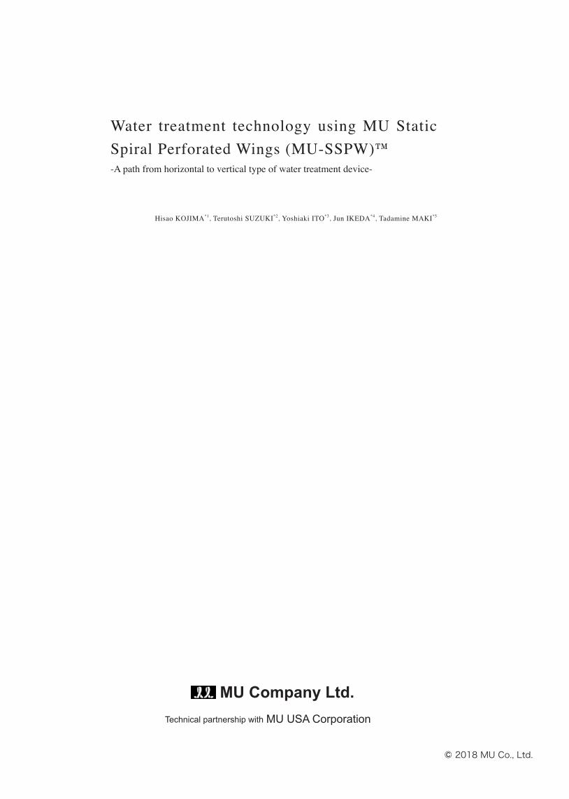
3.2 Relationship between waterfalls and MU Mixing
Element
MU Mixing Element embodies the law of nature
artificially and efficiently by the refinement of water and
its successive expansion of the contact area of liquid-gas
phase like waterfalls (Fig. 11). MU Aqua Tower is a water
treatment tower to be installed on the ground. Some layers
consisted of MU Mixing Element are packed in the tower.
When liquid falls through the elements, oxygen in air can be
taken into liquid. With regards to the fl ow of water, fi rstly,
water is pumped up to the top of the tower and then falls
down through the MU Mixing Element, which makes water
divided into pieces. The division leads to the expansion
of the superficial area of water, which promotes the large
volume of oxygen dissolved into water. The MU Mixing
Element in the tower works as the bumpy surface of a rock
in waterfalls. Only using the energy created by gravity, the
tower reproduces the physical function of waterfalls.
3.3 Outline of principle of MU Aqua Tower
In MU Aqua Tower, the collision energy of falling,
brought by the potential energy of the liquid, can be
converted into shearing forces in a myriad of directions,
which divides liquid into pieces to increase the superfi cial
area of liquid-gas phase. The Element is the heart of our
products. So, what is MU Mixing Element all about? Inside
MU Aqua Tower, multiple elements are placed, creating
a cylindrical static mixer. Inside the element, multiple
perforated wings are placed spirally and the center of the
element in an axial direction is void. Because of the spiral
placement of multiple perforated wings in an element,
every time the liquid passes through the element, the liquid
is continuously divided and mixed over time.
3.4 Principle of MU Mixing Element
So, why do spirally-twisted perforated wings suit for
increasing the superficial area of liquid-gas phase? When
the spiral wings have a lot of holes, a part of liquid fl owing
down along the wings pass through the holes on the wings.
By passing through the holes, the different flow arises,
together with the swirling current along the surface of the
wings. These two different fl ows promote refi nement of the
liquid and another split is occurred by hitting each other.
Now, when it comes to the form of spiral, the surface curves
seamlessly and spirally from the top to the bottom. Now the
liquid is fl owing along the curving surface, moving spirally,
which means that the moving distance from the top to the
bottom is longer than the distance of free-falling, the one of
vertical straight line. Since the distance of liquid moving on
the surface is longer than the one of liquid falling straight
down, the time of contacting liquid with gas is also longer
than the time of free-falling. Moreover, as there are a lot
of holes on the surface, some of the liquid on the surface is
falling down from holes onto the lower wings. The moment
Photo 3 Angel Fall (Venezuela)*6
Fig. 11 Comparison between waterfalls and MU-SSPW
5

the liquid is coming on the verge of the hole, its movement
and direction are decided by the inertial force along the
blade, the viscosity, the strength and direction of force of
wind. The very moment the liquid is about to fall down
from the hole, the shearing force is brought by the gravity,
which promotes the segmentation of the liquid. Inside the
cylinder of MU Mixing Element, are several perforated
wings set. The wings are set at any regular interval, and
the more the area of the surface of wings per volume of the
cylinder is, the more often the liquid fl owing on the surface
of the wings falls down onto the surface of the downer
wings through the holes.
The more the area of wings per volume is, the more
often liquid passes through the holes on the surface of
wings, which means that liquid should be split into pieces
more often. The density of area of wings is determined by
two index. The one is the number of wings contained in an
element. The other is the gentleness of curing of the wings.
The more the number of wings is, the more the density of
wings per volume is. Likewise, the more gentle the curving
of wings is, the bigger the area of the wings is and the more
the density of wings per volume is. The value obtained by
dividing the area of wings with the volume of the element
is defi ned as the effi ciency of gas-liquid phase contact (m2/
m3). The value is the key factor for scaling up the element.
These multiple wings are set inside MU Mixing Element
as mentioned above. With regards to the way the wings are
fi xed, the inner periphery of the wings is welded onto the
rings placed at the center of the circle of the elements. The
outer periphery of the wings is also welded on the inner
surface of the cylinder covering the whole wings. Since
the rings are placed at the center of the element, the void
is generated at the center in an axial direction. In the axial
hole, there are no obstacle to block the axial fl ow of fl uid.
That means that the liquid passing through the hole free-
falls and reaches at the bottom of the element. The axial
free-fall flow is in a different direction from the spiral
fl ow along the wings. Along the boundary phase between
the axial flow through the void and spiral flow along the
wings, the forces with different direction also work, which
generates the shearing force on the boundary. The shearing
forces also urge the liquid to be divided into pieces.
Now, let me wrap up the features of spiral perforated
wings consisting of MU Mixing Element. First, the
spirally perforated wings add the liquid fl owing the wings
with some different kinds of shearing force in a various
direction. The shearing force is generated when liquid
passes through the holes on the surface of the wings and
the liquid hit another fl ow of liquid falling down from the
upper hole of the wings, and the axial flow in the center
contacts the spiral fl ow along the perforated wings. These
shearing forces with different directions enlarge the contact
area of gas-liquid phase. Plus, the curving of the wings
makes the flowing distance longer and the contact area
bigger, which promote further refi nement of the liquid. MU
Mixing Element is an high effi cient aeration device backed
by the laws of nature, which are geometrically condensed
and controlled by perforated spiral form and the difference
between axial and spiral fl ows.
3.5 Features of MU Aqua Tower
3.5.1 High effi ciency and Saving space
Now let me explain the feature of MU Aqua Tower,
which contains MU Mixing Element. The main feature of
MU Aqua Tower is the enhanced aeration power brought by
the expanded area of liquid-gas phase. The increased area
results from the vertically piled up MU Mixing Element
(Fig. 12). A conventional aerator is usually installed in
water, but MU Aqua Tower is installed on the ground,
not in water. The liquid-gas phase is increased not by
sending air into water, but by dividing the target liquid into
pieces. This is to say that the oxygen is taken into liquid
by dividing water into pieces like waterfalls and wrapping
the liquid with the surrounding air, not by infusing air into
water. Using this way, aside from taking gas into liquid,
when highly volatile substances, such as ammonia, dissolve
(Air Diffuser)Conventional
MU
Air
Aeration by feeding air into water and dividing air into pieces
Aeration by dividing water into pieces to increase contact area of liquid-gas phase
Fig. 12 Comparison between horizontal aeration device (diffuser) and vertical aeration device (MU Aqua Tower)
6

into liquid, the substance can be efficiently got rid of from
the liquid. And, by piling up the elements vertically and
putting them inside the tower, a large volume of aeration
can be performed only with a small space. Conventional
aeration system needs a somewhat large space according
to the volume of water. But MU Aqua Tower achieves
high efficiency and saving space of the aeration system by
making liquid impalpable.
3.5.2 No maintenance by self-purification
Another feature of MU Aqua Tower is self-purification.
By washing away dirtiness on the surface like waterfalls,
the device doesn’t need any maintenance. By the way,
when looking into waterfalls carefully, the surface of rocks
near the waterfalls is totally different up to how water hits
the surface. The areas where the waterfalls always hit and
a sheet of spray is created have naked rock surface with
no mosses grown. The other areas, where the waterfalls
don’t hit and mist and moisture are created by the damp of
waterfalls, are covered with mosses (Photo 4). When water
falling down from the upper hit on the surface of a rock, the
power with the rocky surface divides the water. On the other
side, the falling water is hit on the surface and the water
pressurizes the surface, which gets rid of any attachment on
it. Water, together with the potential energy, is not only hit
into pieces, but also clean the surface, up to the condition
of the volume of flow of water, the shape of the surface of
a rock, and the angle of water hit onto the rock surface. The
fracture of water makes the surface of rock clean. This is
true of MU Aqua Tower. When the liquid flows down on
the surface of perforated wings of MU Mixing Element and
it moves on the verge of a hole on it, the direction of flow
of liquid dramatically changes and the liquid falls down
through the hole. When it hit on the edge of a hole, the
flow of water is torn by the gravity to divide the water into
pieces. Up to the flow of water, velocity, and how the water
hit on the edge of a hole, it is decided how water is divided
into pieces. In the process of the segmentation of water, the
end of a hole is pressured by the force of the segmentation
of water, and the force makes the surface of wings clean.
Some water falling down through the holes hit on the lower
wings and clean the surface. In this way, by dividing water,
the perforated spiral wings get clean. For this product, to
divide water into pieces is to purify the wings themselves.
3.6 Application of MU Aqua Tower
In this way, features of MU Aqua Tower are a highly
efficient and space-saving device due to the vertical type of
aeration, and free-of-maintenance. This tower is basically
installed on the ground, but this application, due to its high
efficiency and saving space, is wider than any conventional
aerators. For example, this tower can be installed on the
surface of the closed water, such as a pond and lake, and be
floating on it by making a structure and putting on it. MU
Aqua Tower is originally a device to increase a contact area
of the liquid-gas phase to dissolve oxygen with water, but
it can strip volatile compound, like ammonia, contained in
water into air (Ammonia Stripping). In the next chapter,
we will explain how MU Aqua Tower as vertical aerator
applies.
4. Water purification device using MU Mixing Element4.1 Type and Mechanism
In this chapter, we introduce a list of water purification
device with MU Mixing Element. Fig. 13 shows an
example of the use of these devices, including MU Aqua
Tower, MU Green Reactor and MU Floating Tower.
MU Aqua Tower is a tower type aerator with multiple
layers of MU Mixing Element, free-falling water pumped
Photo 4 Details of waterfalls
7

up from lake or pond by a circulation pump to create
artificial waterfalls and purify water effectively. The device
is to dissolve oxygen into water by free-falling and crashing
water with MU Mixing Element to divide water into pieces.
The neighborhood of area where water should be purified,
such as the shore of lake/pond, is often selected as a
location of its installation.
MU Green Reactor is a water purification device used
in the bottom of lake/pond. Root blower and compressor
send fresh pressurized air into the bottom of the device to
generate microbubble for adding oxygen into water. Air sent
to the bottom of the device will be going up to the surface
of water by buoyant force. By passing through some layers
of Mixing Element, the air is divided into pieces, which
generates microbubbles to help oxygen in the bubble
dissolve into water.
MU Floating Tower is the smaller one than MU
Aqua Tower and MU Green Reactor to float it on the
water surface. MU Floating Tower has two types: a
type with compacted MU Aqua Tower and the other
type with MU Green Reactor in the underwater
casing. Both can be floating like a ship and easy to
remove and available for water purification of a wide
area. The structure and type of MU Floating Tower
are described as follows.
Fig. 14 shows the comparison of three types of aeration.
All of the devices make the most use of laws of nature,
like free-falling and the buoyant force of air in water,
which can save energy as possible as it can. In the middle
of worldwide serious energy shortage, the series is the
futuristic water purification devices. Furthermore, all
devices are designed to be compact, saving-space, saving-
energy, and free-of-maintenance, which has little influence
with ecological system.
4.2 Usage Area of MU Floating Tower
It seems that the biggest issue of water environment in
the 21st century is the improvement of water in the closed
water like lake and pond where the water is not likely to be
Fig. 13 Types of water purification device using MU-SSPW
Fig. 14 Performance comparison of water purification device
8

circulated. In recent years, the quality of water in the river
is improving, but the water in a lake and pond is said to be
difficult to be improved because the large volume of energy
is needed. MU Floating Tower is being developed as an
effective device for improving the water quality in a wide
area, like lake and pond.
4.3 Basic structure of MU Floating Tower
MU Floating Tower is a water purification device
embedding compacted MU Aqua Tower or MU Green
Reactor into a part of a floating body like a ship. When
MU Green Reactor is embedded, double pipes are used
to insert into the water, generating water circulation and
microbubble by the effect of the airlift.
Fig. 15 shows an example of installation of MU
Floating Tower. Since the device can move and float on
the surface freely, this can be installed on the closed water
like lake and pond easily, and this advantage can evoke
further utilization of the device. With the solar/wind power
generation device on the top of it, the power can be self-
generated for pumping water and air. Realizing this system
can build a system of semi-permanent water purification.
4.4 Four Types of MU Floating Tower
Fig. 16 shows four types of MU Floating Tower as
follows.
1. Aqua Tower Type
Compacted MU Aqua Tower is installed at the center of this
device. Water is purified by falling down water from the
top of the device by lifting pump and passing through MU
Mixing Element. This is suitable for the shallow water.
2. Casing Type
MU Mixing Element is installed in the underwater casing of
the center of the device. The device generates microbubbles
Fig. 15 An example of MU Floating Tower
Fig. 16 Type of MU Floating Tower
9

by blowing the compressed air by a blower from the bottom
of the underwater casing. Shallow water is also suitable.
3. Air Lift Type
Air compressed by a blower is sent to MU Green
Reactor, installed in a double tube at the center of the
device, and the large volume of microbubbles are generated.
The deeper water is available for this type.
4. Green Reactor Type
MU Green Reactor is sunk at the bottom of the water
using a winch and compressed air is sent to MU Green
Reactor by a sunny hose. Since microbubble can be
generated from the bottom of the water, a large volume of
water can be improved.
4.5 Feature of MU Floating Tower
As mentioned above, MU Floating Tower has a potential
for a variety of use due to the features, such as mobility,
saving-energy, and a variety of types. The Tower also has
the advantages of compactness, maintenance free, and
friendly to the natural ecosystem. The simple design seems
to avoid damaging the scenery of the shore of a lake or
pond. It would be grateful if MU Floating Tower would be
installed everywhere in the world as a water purification
device with permanency which exceeds the human
timescale.
4.6 Synergetic effect of MU Green Reactor and MU
Aqua Tower
MU Green Reactor can generate strong circulation flow
and when MU Aqua Tower is used together with MU Green
Reactor in the big closed water, the effective increase of
dissolved oxygen can be performed (Fig. 17). Fig. 17
contains (1) retention tank, (2) aeration tank and (3) settling
tank. In the aeration tank, are (4) MU
Aqua Tower and (5) MU Green Reactor
installed.When MU Aqua Tower is injected
with O2 gas, the tower can be a device for
ozone treatment. Likewise, when the tower
is injected with air, the tower can be a
stripping tower of NH3, H2S.
5. Conclusion With “Why do waterfalls and surge look
white?” as an origin of our ideas, we, MU
Company Ltd., have forwarded step by step
for 35 years to research and develop a variety of devices
with the advantages of high efficiency, free-of-maintenance,
and saving-energy toward the conservation of the global
environment. Though a record track of MU-SSPW in the
field of wastewater treatment is not so much, in this paper,
we describe how MU-SSPW can be applied to wastewater
treatment, explaining the device with the integration of
regenerated energy, such as solar and wind power, free-fall
energy from the law of waterfalls, potential energy. It will
be our sincere desire to make a persistent effort for better
products, thinking of the transforming from the horizontal
to vertical type of wastewater treatment device, with the
notion of reproduction and coexistence.
Now the sea is lull in the wind.
“Sakura Sakura Waga Shiranui ha Hikari Nagi*7” (Michiko
Ishimure, “Ten”)
*1 Hisao KOJIMA: President of MU Company Ltd., A member of American Chemical Society*2 Terutoshi SUZUKI: Manager of Technical Devision of MU Company Ltd.*3 Yoshiaki ITO: Adviser of MU Company Ltd., Certified Architect*4 Jun IKEDA: Adviser of MU Company Ltd., Certified Architect*5 Tadamine MAKI: Deputy Manager of Technical Devision of MU Company Ltd.*6 https://www.flickr.com/photos/ent108/2184549701/in/gallery-flickr-72157644747506520/ (as of June 30, 2018)*7 meaning “Sakura, Sakura, on my sea, Shiranui Sea, some glittering on the surface, lull in the wind” The sea was famous for the place of Minamata disease, and used to be polluted by the industrial wastewater and perhaps the sea is glittering due to some chemical pollutant. This poem by Michiko Ishimure gently describes "all life" which return eternally and regenerate circularly, with affection for wonder that all life exist here now, not "human beings" which exist from birth to death linearly.Note) This paper is originally written in Japanese and included in a journal, Kagaku Sochi (Plant and Process), vol. 60, no. 8 (Aug. 2018), pp. 33-42, published by KOGYO TSUSHIN CO., Ltd. The paper was partly revised and added.
Fig. 17 Combined application of MU Aqua Tower and MU Green Reactor
(1) Retention tank(2) Aeration tank(3) Settling tank
(4) MU Aqua Tower
(5) MU Green Reactor
10


![SummaryMap ward2 [Converted] · 2019-10-01 · MU-2 MU-6 MU-16 MU-14 MU-6 MU-2 MU-20 MU-9 MU-4 MU-13 MU-15 MU-13 MU-16 MU-18 MU-22 MU-19 MU-16 MU-27 MU-4 MU-3A MU-17 MU-13 MU-4 ...](https://static.fdocuments.us/doc/165x107/5f5e4f591750d150e9633369/summarymap-ward2-converted-2019-10-01-mu-2-mu-6-mu-16-mu-14-mu-6-mu-2-mu-20.jpg)