
Water Treatment Industry Solutions - · PDF fileWater Treatment Industry Solutions Waste...
28
Water Treatment Industry Solutions Waste water treatment Water purification plant Intermediate water reuse Municipal pump station
Transcript of Water Treatment Industry Solutions - · PDF fileWater Treatment Industry Solutions Waste...

Water Treatment Industry Solutions
Waste water treatment
Water purification plant
Intermediate water reuse
Municipal pump station
Water Treatment Industry Solutions
http://www.hollysys.com.sg P a g e | 1
Waste water treatment plant
1. Treatment process procedures
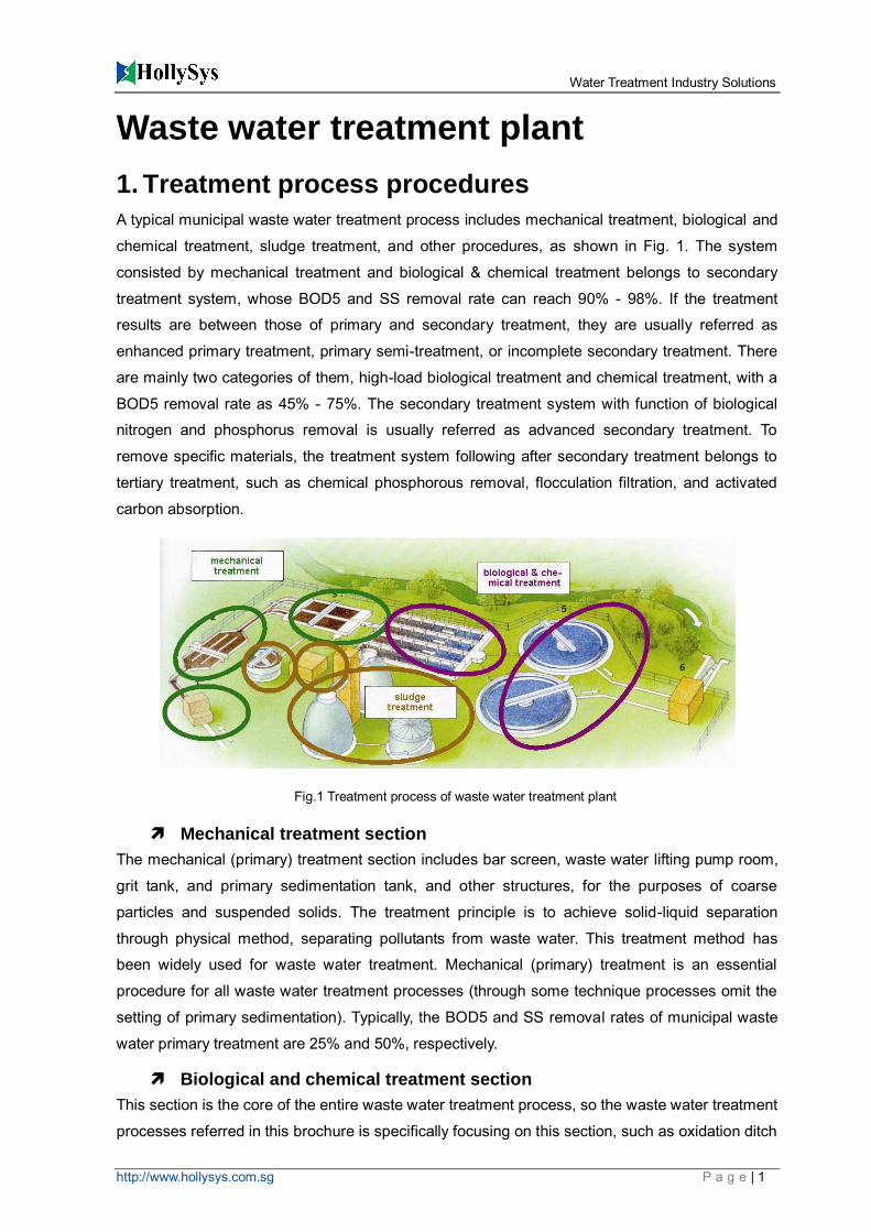
A typical municipal waste water treatment process includes mechanical treatment, biological and
chemical treatment, sludge treatment, and other procedures, as shown in Fig. 1. The system
consisted by mechanical treatment and biological & chemical treatment belongs to secondary
treatment system, whose BOD5 and SS removal rate can reach 90% - 98%. If the treatment
results are between those of primary and secondary treatment, they are usually referred as
enhanced primary treatment, primary semi-treatment, or incomplete secondary treatment. There
are mainly two categories of them, high-load biological treatment and chemical treatment, with a
BOD5 removal rate as 45% - 75%. The secondary treatment system with function of biological
nitrogen and phosphorus removal is usually referred as advanced secondary treatment. To
remove specific materials, the treatment system following after secondary treatment belongs to
tertiary treatment, such as chemical phosphorous removal, flocculation filtration, and activated
carbon absorption.
Mechanical treatment section
The mechanical (primary) treatment section includes bar screen, waste water lifting pump room,
grit tank, and primary sedimentation tank, and other structures, for the purposes of coarse
particles and suspended solids. The treatment principle is to achieve solid-liquid separation
through physical method, separating pollutants from waste water. This treatment method has
been widely used for waste water treatment. Mechanical (primary) treatment is an essential
procedure for all waste water treatment processes (through some technique processes omit the
setting of primary sedimentation). Typically, the BOD5 and SS removal rates of municipal waste
water primary treatment are 25% and 50%, respectively.
Biological and chemical treatment section
This section is the core of the entire waste water treatment process, so the waste water treatment
processes referred in this brochure is specifically focusing on this section, such as oxidation ditch
Fig.1 Treatment process of waste water treatment plant
Water Treatment Industry Solutions
http://www.hollysys.com.sg P a g e | 2
method, SBR method, and A/O method. The biological and chemical treatment of waste water is
secondary treatment to remove suspended solids and soluble biodegradable organic matter as
main purposes. Currently, most municipal waste water treatment plants use activated sludge to do
that. The principle of biological & chemical treatment is to complete decomposition of organic
matter and synthesis of organisms through biological role, especially the role of micro-organisms,
turning organic pollutant into harmless gaseous products (CO2), liquid products (water), and
organic-rich solid products (also known as microbial community or bio-sludge). The excess
bio-sludge in the sedimentation tank goes through solid-liquid separation by sedimentation, and is
removed from purified water.
Sludge treatment section
The sludge generated from the biological & chemical treatment firstly arrives at sludge pump
room. Some sludge is sent back to the biological & chemical treatment section. Other sludge
quickly enters into the sludge concentration tank through sludge pump. After concentrated in the
sludge concentration tank for a certain period of time, the supernatant flows back to the collecting
tank at the waste water lifting pump room. The concentrated sludge comes to the sludge
conditioning tank, lifting to sludge dewatering room through the sludge pump. After dehydrated in
the sludge dewatering room, the sludge is made into mud-cake and sent out.
2. Common waste water treatment methods
At present, the common waste water treatment methods include A2/O, oxidation ditch, SBR,
CASS, CAST, AB, biological contact oxidation (BCO), biological aerated filter (BAF), biofilm, etc.
A2/O method
A2/O biological nitrogen and phosphorus removal process has combined conventional activated
sludge process, biological nitrification and denitrification process, and biological phosphorus
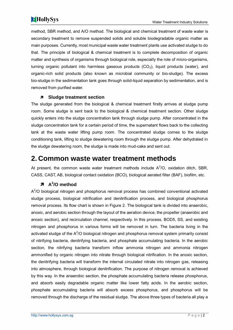
removal process. Its flow chart is shown in Figure 2. The biological tank is divided into anaerobic,
anoxic, and aerobic section through the layout of the aeration device, the propeller (anaerobic and
anoxic section), and recirculation channel, respectively. In this process, BOD5, SS, and existing
nitrogen and phosphorus in various forms will be removed in turn. The bacteria living in the
activated sludge of the A2/O biological nitrogen and phosphorus removal system primarily consist
of nitrifying bacteria, denitrifying bacteria, and phosphate accumulating bacteria. In the aerobic
section, the nitrifying bacteria transform inflow ammonia nitrogen and ammonia nitrogen
ammonified by organic nitrogen into nitrate through biological nitrification. In the anoxic section,
the denitrifying bacteria will transform the internal circulated nitrate into nitrogen gas, releasing
into atmosphere, through biological denitrification. The purpose of nitrogen removal is achieved
by this way. In the anaerobic section, the phosphate accumulating bacteria release phosphorus,
and absorb easily degradable organic matter like lower fatty acids. In the aerobic section,
phosphate accumulating bacteria will absorb excess phosphorus, and phosphorus will be
removed through the discharge of the residual sludge. The above three types of bacteria all play a
Water Treatment Industry Solutions
http://www.hollysys.com.sg P a g e | 3
role in removal of BOD5, which is mainly fulfilled by the denitrifying bacteria.
Oxidation-reduction potential (ORP) and dissolved oxygen (DO) as the main control parameters,
the treatment is regulated on aeration system, internal returning system, external returning
system, and residual sludge disposal system, achieving a good efficiency on nitrogen and
phosphorus removal, effective reduction of BOD5 in waste water. Meanwhile, it also maximizes
energy saving, ensuring the highly efficient and stable operating of the whole system.
Oxidation ditch method
Oxidation ditch is also known as oxidation channel, because its structure was named after a
closed loop ditch. It is a variant of the activated sludge. Because waste water and activated
sludge are continuously cycling in aeration channels, some people call it a “cyclic aeration tank” or
“endless aeration tank”. The oxidation ditch has long hydraulic retention time, and its organic load
is low, belonging to extended aeration system in nature.
Oxidation ditch uses a continuous loop reactor (CLR) as bio-reactor. Liquid mixture undergoes
continuous cycles inside a closed aeration channel of the CLR. The oxidation ditch often is used
under conditions of extended aeration. Utilizing directional controlled aeration and agitation
devices, the ditch transfer horizontal speed to the mass inside the CLR, making the stirred liquid
circulate in the closed loop channel.
The oxidation ditch generally consists of ditch, aeration equipment, water inlet and outlet devices,
diversion and mixing equipment. The 2D shape of the ditch is usually circular, but it can be
rectangular, L-shaped, round, or other shapes. The cross-section shape of the ditch is mostly
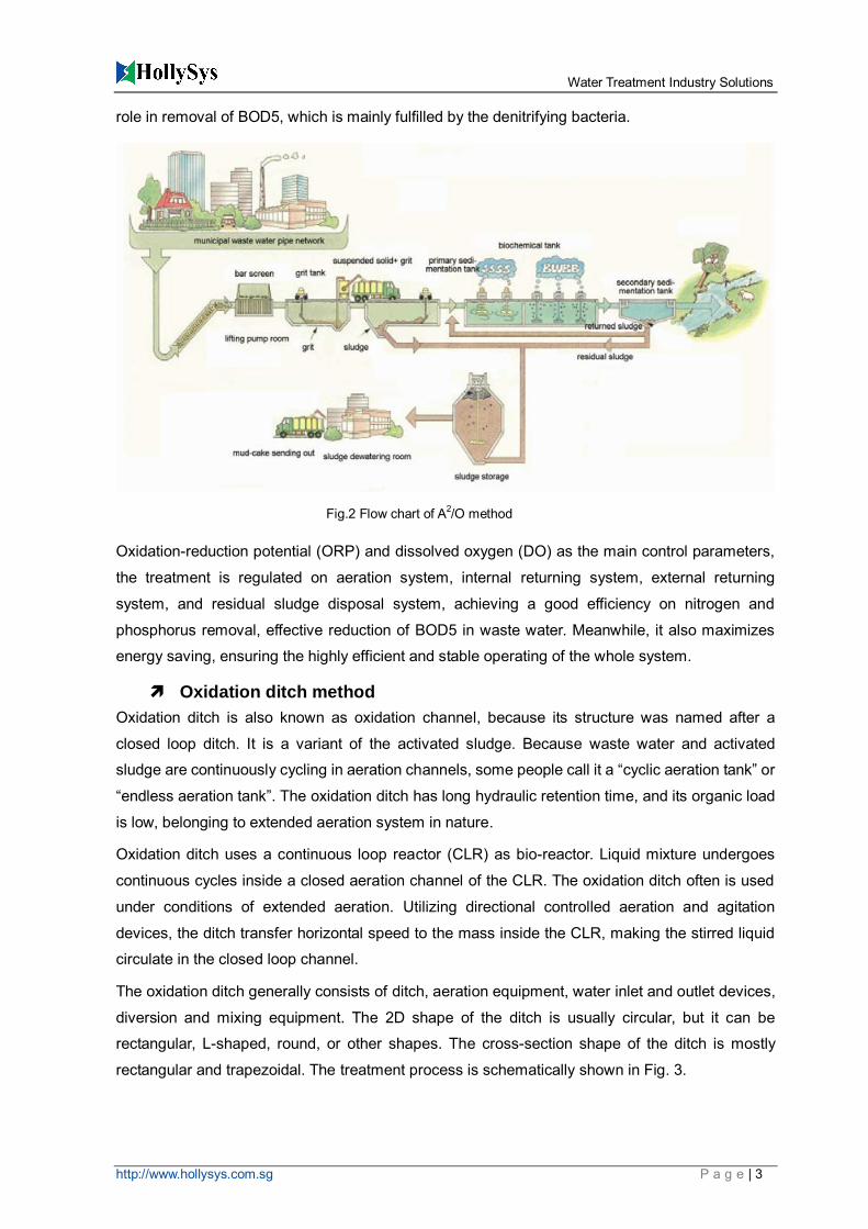
rectangular and trapezoidal. The treatment process is schematically shown in Fig. 3.
Fig.2 Flow chart of A2/O method
Water Treatment Industry Solutions
http://www.hollysys.com.sg P a g e | 4
Oxidation ditch method features a long hydraulic retention time, low organic loading, and long
sludge life. Compared to conventional activated sludge process, the designers can omit the
conditioning tank, primary sedimentation tank, sludge digestion tank, and sometimes the
secondary sedimentation tank can also be omitted. The oxidation ditch can guarantee good
treatment effect, mainly because it cleverly combines the CLR form and positioning of a particular
arrangement of aeration devices. This brings the oxidation ditch with unique hydraulic and
operational characteristics.
With the development of the oxidation ditch process, current relatively representative forms of this
method in engineering applications are multi-channel alternating oxidation ditch (e.g.,
three-channel type and five-channel type) and its modified forms, Carrousel oxidation ditch and its
modified forms, Orbal oxidation ditch and its modified forms, and integrated oxidation ditch.
SBR method
SBR is the abbreviation form of Sequencing Batch Reactor Activated Sludge Process, a type of
activated sludge waste water treatment technology using intermitted aeration mode. It has
different Chinese translation names. Compared to the traditional waste water treatment, SBR
technology uses time-dividing operation mode instead of space-dividing, non-stable biochemical
reactions instead of stable ones, and static ideal sedimentation instead of traditional dynamic
sedimentation. Its main features are orderly and intermittent operation. The core of SBR
technology is SBR reactor, with the integrated functions of homogenization, primary
sedimentation, biological degradation, and secondary sedimentation. It needs no sludge returning
Fig. 3 Flow chart of oxidation ditch method
Water Treatment Industry Solutions
http://www.hollysys.com.sg P a g e | 5
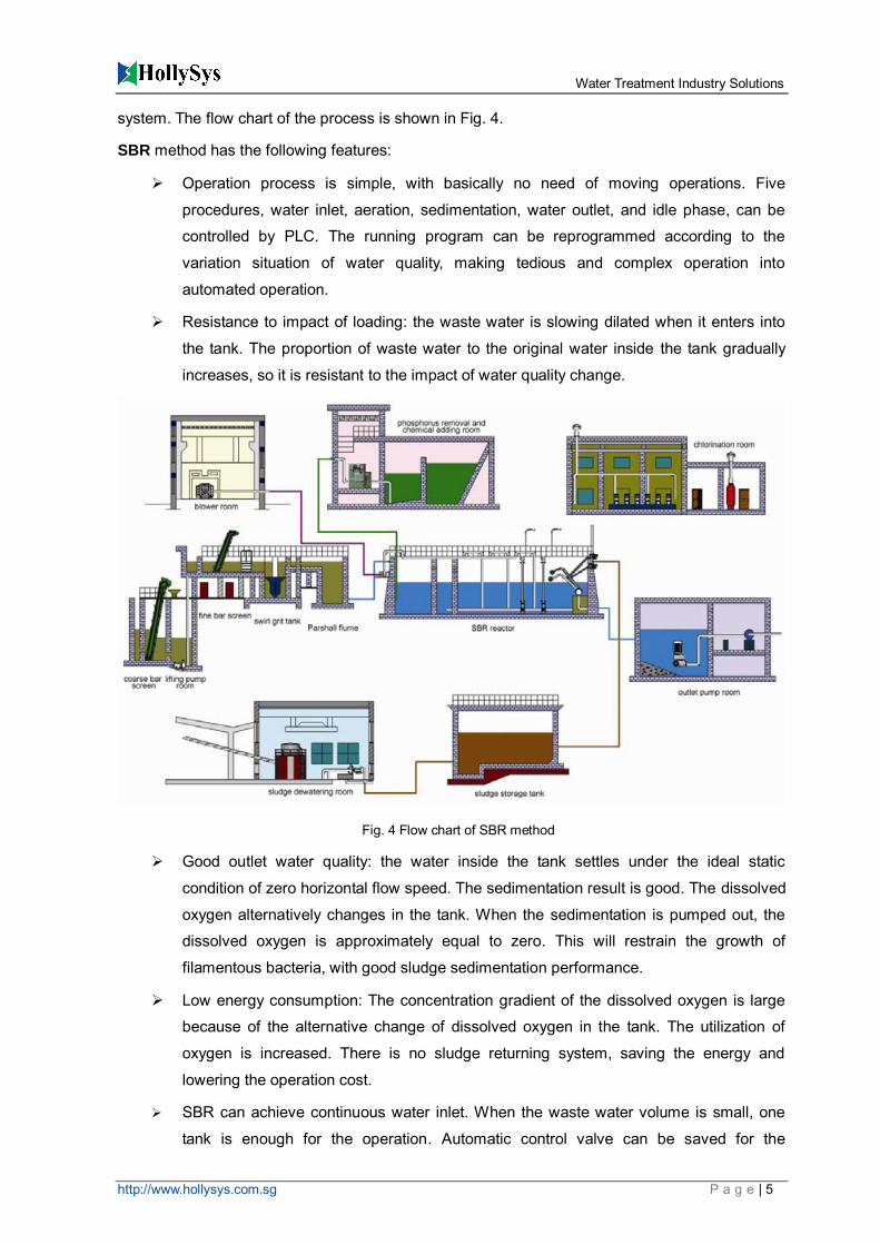
system. The flow chart of the process is shown in Fig. 4.
SBR method has the following features:
Operation process is simple, with basically no need of moving operations. Five
procedures, water inlet, aeration, sedimentation, water outlet, and idle phase, can be
controlled by PLC. The running program can be reprogrammed according to the
variation situation of water quality, making tedious and complex operation into
automated operation.
Resistance to impact of loading: the waste water is slowing dilated when it enters into
the tank. The proportion of waste water to the original water inside the tank gradually
increases, so it is resistant to the impact of water quality change.
Good outlet water quality: the water inside the tank settles under the ideal static
condition of zero horizontal flow speed. The sedimentation result is good. The dissolved
oxygen alternatively changes in the tank. When the sedimentation is pumped out, the
dissolved oxygen is approximately equal to zero. This will restrain the growth of
filamentous bacteria, with good sludge sedimentation performance.
Low energy consumption: The concentration gradient of the dissolved oxygen is large
because of the alternative change of dissolved oxygen in the tank. The utilization of
oxygen is increased. There is no sludge returning system, saving the energy and
lowering the operation cost.
SBR can achieve continuous water inlet. When the waste water volume is small, one
tank is enough for the operation. Automatic control valve can be saved for the
Fig. 4 Flow chart of SBR method

Water Treatment Industry Solutions
http://www.hollysys.com.sg P a g e | 6
distribution on the waste water flow change with the time. Also, only one decanter is
needed. This makes a much simpler tank structure.
CAST method
Cyclic Activated Sludge Technology (CAST) is a cyclic activated sludge method. CAST system
has an intermittent reactor, where activated sludge process constantly repeats aeration and
non-aeration phase alternatively. The biological reaction processes and mud separation process
are carried out in one tank. The flow chart is shown in Fig. 5.
CAST process is a “water filling and drainage” activated sludge method. The waste water
undergoes cyclic treatment according to a certain time period. CAST technology modified from
SBR method. Its each cycle is comprised of the following stages: inflatable/aeration, filling
water/sediment, draining water, and idle section. Those four stages form a loop and repeating
cycle. At the beginning, water-filling makes the minimum water level to rise. After a certain period
of time of aeration and mixing, aeration stage is ended so that activated sludge will flocculate and
settle in a static environment. After completion of the sedimentation stage, supernatant is
discharged by a movable draining weir. When the water level decreases to the preset minimum
level, the entire process will repeat from the start.
CAST tank is divided into three zones, namely, selection zone, oxygen-deficient zone, and
primary aeration zone. In the selection zone, the dissolved organic matter in waste water is rapidly
removed through enzyme reaction mechanism. The volume of this zone can be constant or
variant for operation. For multi-tank systems, the inlet and distributing tank can also be used as
Fig.5 Flow chart of oxidation ditch method

Water Treatment Industry Solutions
http://www.hollysys.com.sg P a g e | 7
select zone. The nitrate of the returned sludge is denitrified in the selection zone. The most basic
function of this zone is to prevent the development of sludge swelling. In the oxygen deficient
zone, there is small amount of aeration, to regulate aeration zone for phosphorus removal with no
oxygen. The primary aeration zone mainly undergoes degradation of organic compounds and
nitrification process, also engages in nitrification - denitrification process.
CASS method
Cyclic Activated Sludge System (CASS) is a type of cyclic activated sludge technology (CAST). Its
main principle is to divide sequencing batch reactor (SBR) into two parts along the length
direction. The front part is pre-reaction zone, and the rear is the primary reaction zone. In the
pre-reaction zone, micro-organism rapidly absorbs soluble organic matter in the waste water
through the mechanism of rapid enzyme movement. This rapid high-load substrate accumulation
process play a role of buffer effect on water quality, water flow, pH value, and toxic materials,
effectively preventing sludge from swelling. Followingly in the primary reaction zone, organic
matter in the waste water is degraded through a process of low-load substrate degradation. The
CASS process can fully release the degradation function of activated sludge. Also it alleviates
burden of the secondary sedimentation tank, helping improve the solid-liquid separation efficiency
of the tank.
AB method
Adsorption biodegradation (AB) is a new type of dual biological treatment process. Compared with
the conventional activated sludge, it has high efficiency and stability, with energy saving and low
cost advantages. A typical AB process is: waste water – bar screen – grit tank - Section A aeration
tank - middle sedimentation tank (sludge is returned to Section A aeration tank) - Section B
aeration tank - secondary sedimentation tank (sludge is returned to Section A aeration tank) –
water outlet. Breakthrough of the AB technology is mainly in Section A. This section eliminates the
need for a primary sedimentation tank. The Section A aeration tank is operating at high-load [
2kg BOD5/(kgMLSS•d)], short residence time (30 min), low dissolved oxygen (0.5-1 mg/L), and
short sludge retention time (0.5-0.7 d). However, the working mechanism study for Section A of is
not making big progress. For instance, in the absence of sludge regeneration the system is able to
maintain microbial activity and good sludge settling characteristics, which cannot be explained by
the traditional microbial oxidation of adsorption mechanisms.
The method has excellent pollutant removal ability, strong load resistant capacity, good nitrogen
and phosphorus removal performance, and lower investment and running costs.
Efficient organic substrate removal
The system is running stable, with features of small fluctuations in water quality, strong
resistance to load impact, and good sludge settling characteristics.
Efficient nitrogen and phosphorus removal
Energy saving: Low operation cost and power consumption, with recyclable biogas
Water Treatment Industry Solutions
http://www.hollysys.com.sg P a g e | 8
energy. The experiment proved that AB method can save operating cost savings 20% ~
25% more than traditional single section treatment process.
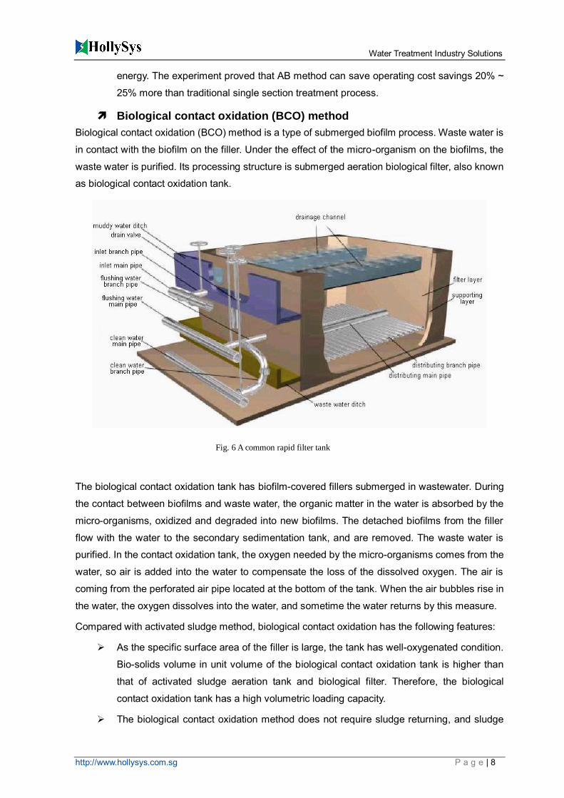
Biological contact oxidation (BCO) method
Biological contact oxidation (BCO) method is a type of submerged biofilm process. Waste water is
in contact with the biofilm on the filler. Under the effect of the micro-organism on the biofilms, the
waste water is purified. Its processing structure is submerged aeration biological filter, also known
as biological contact oxidation tank.
The biological contact oxidation tank has biofilm-covered fillers submerged in wastewater. During
the contact between biofilms and waste water, the organic matter in the water is absorbed by the
micro-organisms, oxidized and degraded into new biofilms. The detached biofilms from the filler
flow with the water to the secondary sedimentation tank, and are removed. The waste water is
purified. In the contact oxidation tank, the oxygen needed by the micro-organisms comes from the
water, so air is added into the water to compensate the loss of the dissolved oxygen. The air is
coming from the perforated air pipe located at the bottom of the tank. When the air bubbles rise in
the water, the oxygen dissolves into the water, and sometime the water returns by this measure.
Compared with activated sludge method, biological contact oxidation has the following features:
As the specific surface area of the filler is large, the tank has well-oxygenated condition.
Bio-solids volume in unit volume of the biological contact oxidation tank is higher than
that of activated sludge aeration tank and biological filter. Therefore, the biological
contact oxidation tank has a high volumetric loading capacity.
The biological contact oxidation method does not require sludge returning, and sludge
Fig. 6 A common rapid filter tank
Water Treatment Industry Solutions
http://www.hollysys.com.sg P a g e | 9
swelling problem would not exist, facilitating simple operation and management.
The bio-solids volume is large and the water is completely mixed, so the biological
contact oxidation tank has a stronger adaptability to the sudden changes of water quality
and quantity.
When the bio-contact oxidation tank keeps a high organic volumetric loading, the F/M
remains at a low level, with a low sludge production.
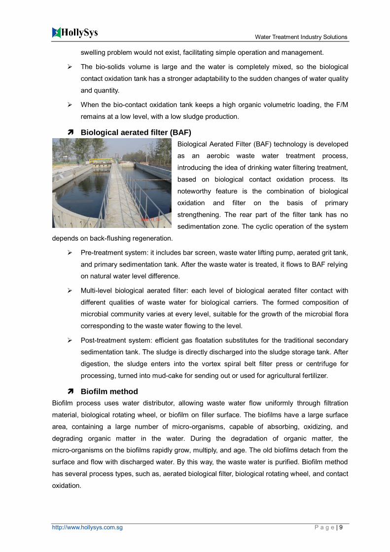
Biological aerated filter (BAF)
Biological Aerated Filter (BAF) technology is developed
as an aerobic waste water treatment process,
introducing the idea of drinking water filtering treatment,
based on biological contact oxidation process. Its
noteworthy feature is the combination of biological
oxidation and filter on the basis of primary
strengthening. The rear part of the filter tank has no
sedimentation zone. The cyclic operation of the system
depends on back-flushing regeneration.
Pre-treatment system: it includes bar screen, waste water lifting pump, aerated grit tank,
and primary sedimentation tank. After the waste water is treated, it flows to BAF relying
on natural water level difference.
Multi-level biological aerated filter: each level of biological aerated filter contact with
different qualities of waste water for biological carriers. The formed composition of
microbial community varies at every level, suitable for the growth of the microbial flora
corresponding to the waste water flowing to the level.
Post-treatment system: efficient gas floatation substitutes for the traditional secondary
sedimentation tank. The sludge is directly discharged into the sludge storage tank. After
digestion, the sludge enters into the vortex spiral belt filter press or centrifuge for
processing, turned into mud-cake for sending out or used for agricultural fertilizer.
Biofilm method
Biofilm process uses water distributor, allowing waste water flow uniformly through filtration
material, biological rotating wheel, or biofilm on filler surface. The biofilms have a large surface
area, containing a large number of micro-organisms, capable of absorbing, oxidizing, and
degrading organic matter in the water. During the degradation of organic matter, the
micro-organisms on the biofilms rapidly grow, multiply, and age. The old biofilms detach from the
surface and flow with discharged water. By this way, the waste water is purified. Biofilm method
has several process types, such as, aerated biological filter, biological rotating wheel, and contact
oxidation.

Water Treatment Industry Solutions
http://www.hollysys.com.sg P a g e | 10
3. Automatic control instrument system
3.1 Overview
Oxidation ditch is also known as oxidation channel, because its structure was named after a closed loop ditch. It is a variant of the activated sludge. Because waste water and activated sludge are continuously cycling in aeration channels, some people call it a “cyclic aeration tank” or “endless aeration tank”. The oxidation ditch has long hydraulic retention time, and its organic load is low, belonging to extended aeration system in nature.
Hollysys LK Series Programmable Logic Controller (PLC) based automatic control systems can be applied to waste water treatment plants, fully meeting the requirements of the waste water oxidation ditch treatment process. This provides a high reliable, low-cost, more optimized control solution.
LK series are the medium and high-end performance control field products, developed from the company’s concluding 10 years of control system design and implementation experience based on thousands of projects in the applied field. The instruction processing speed of CPU module integrated industrial-grade processor (frequency up to 533MHz) can reach up to 13 ns. Compared with the traditional PLC, LK fully programmable controller combines the advantages of DCS and PLC, using high-performance analog processing technology, miniaturization of the structural design, open industry standards, and uniform platform. The products not only have the powerful features and superior performance, but also have higher reliability, greater openness and ease of use.
3.2 Automatic control system design
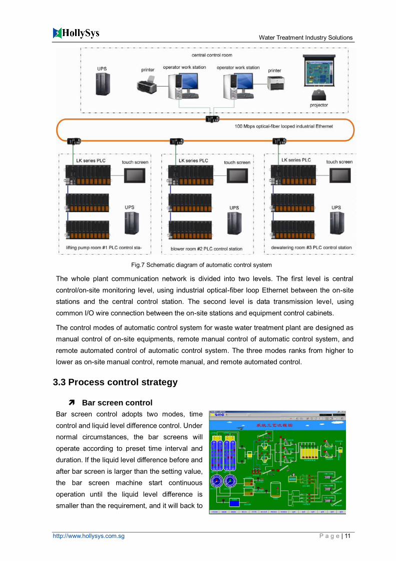
The entire system consists of one central control room and three on-site PLC control stations. The on-site PLC control station is comprised of programmable logic controller (PLC) systems and measuring instruments. It performs distributed controlling on each procedure of waste water treatment process in the plant. The central control room (CCR) takes integrated control on the entire plant. The communication between CCR and PLC control stations adopts high-speed real-time industrial loop-structured Ethernet, with a speed of 100 Mbps and optical fiber as transmission media. The central control station is located at the central control room of comprehensive building. The three on-site control stations are located at inlet pump room (#1 PLC control station), blower room (#2 PLC control station), and sludge squeezing and dewatering room (#3 PLC control station), respectively. They all adopt LK series PLC from Hollysys.
Water Treatment Industry Solutions
http://www.hollysys.com.sg P a g e | 11
The whole plant communication network is divided into two levels. The first level is central control/on-site monitoring level, using industrial optical-fiber loop Ethernet between the on-site stations and the central control station. The second level is data transmission level, using common I/O wire connection between the on-site stations and equipment control cabinets.
The control modes of automatic control system for waste water treatment plant are designed as manual control of on-site equipments, remote manual control of automatic control system, and remote automated control of automatic control system. The three modes ranks from higher to lower as on-site manual control, remote manual, and remote automated control.
3.3 Process control strategy
Bar screen control
Bar screen control adopts two modes, time control and liquid level difference control. Under normal circumstances, the bar screens will operate according to preset time interval and duration. If the liquid level difference before and after bar screen is larger than the setting value, the bar screen machine start continuous operation until the liquid level difference is smaller than the requirement, and it will back to
Fig.7 Schematic diagram of automatic control system

Water Treatment Industry Solutions
http://www.hollysys.com.sg P a g e | 12
normal operation.
The screening transit and squeezing machine operates interlinked with the bar screen machine.
Lifting pump room
The speed and on/off of the pumps are automatically controlled and frequency-adjusted depending on the liquid level of the sump. When the liquid level of the sump reaches the minimum level, the pumps will automatically stop, achieving dry running protection of the pumps. Starting counting and overall running time of each pump are monitored for balance. The initial setting assumes that each pump running time is equal. The running process of the pumps will be monitored by the automatic control system. If any failure occurs to a pump, the system will alarm and automatically start backup pumps.
Grit tank and grit-water separator
The grit transit pump and other electrical equipments, as well as grit-water separator form a system, controlled by the attached control cabinets.
Oxidation ditch
The operation and speed of the rotating wheels are adjusted by PLC according to measured dissolved oxygen values of ditches. The PLC also controls the operation of the propeller sludge scraper bridge.
Returning and residual sludge pump room
The on/off and running time of the returning sludge pump are controlled by PLC depending on the mixture concentration feedback measured in the biological tank.
Substation
PLC does not control substation, which is controlled by station automatic monitoring and control system through communication in RS485 or other interfaces.
Sludge concentration tank
The mixer of the sludge concentration tank runs continuously, manually on/off controlled from on-site electrical control cabinet or controlled by PLC.
Sludge dewatering room
Sludge dewatering machine and its auxiliary machine are controlled by sludge dewatering machine cabinet. When the sludge dewatering machine is running, sludge pump,
chemical adding device, and distributing pump are interlocked to run.
Blower room
Blower control system uses gas signal as master control signal and oxidation ditch dissolved
oxygen signal as auxiliary signal. The regulation valve opening is automatically controlled based
Water Treatment Industry Solutions
http://www.hollysys.com.sg P a g e | 13
on actual loading, for the purpose of control water quality of outlet water. The on/off counting and
overall running time is balanced for each blower.
3.4 Instrument system
For a modern waste water treatment plant, the effluent water quality and automation of operation
management of the wastewater treatment plant rely on dozens of online real-time monitoring and
analysis instruments distributed at various process sections in the plant. The instrument system
follows the design principle of “process necessary, measuring compliance, practical and effective,
maintenance-free”. The waste water treatment plant instrumentation includes two broad
categories, conventional measuring instruments and water analysis instruments.
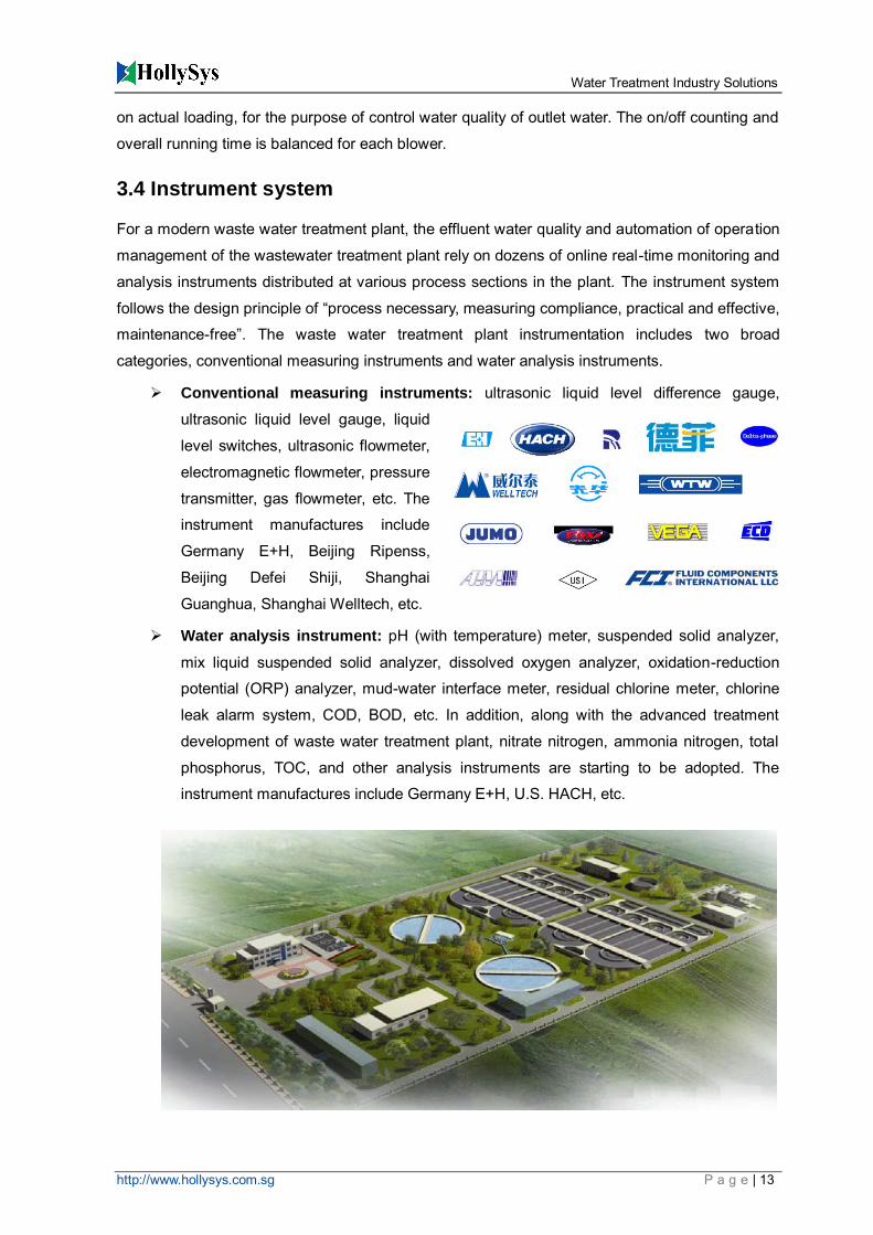
Conventional measuring instruments: ultrasonic liquid level difference gauge,
ultrasonic liquid level gauge, liquid
level switches, ultrasonic flowmeter,
electromagnetic flowmeter, pressure
transmitter, gas flowmeter, etc. The
instrument manufactures include
Germany E+H, Beijing Ripenss,
Beijing Defei Shiji, Shanghai
Guanghua, Shanghai Welltech, etc.
Water analysis instrument: pH (with temperature) meter, suspended solid analyzer,
mix liquid suspended solid analyzer, dissolved oxygen analyzer, oxidation-reduction
potential (ORP) analyzer, mud-water interface meter, residual chlorine meter, chlorine
leak alarm system, COD, BOD, etc. In addition, along with the advanced treatment
development of waste water treatment plant, nitrate nitrogen, ammonia nitrogen, total
phosphorus, TOC, and other analysis instruments are starting to be adopted. The
instrument manufactures include Germany E+H, U.S. HACH, etc.
Water Treatment Industry Solutions
http://www.hollysys.com.sg P a g e | 14
Water purification plant
1. Process of water purification plant
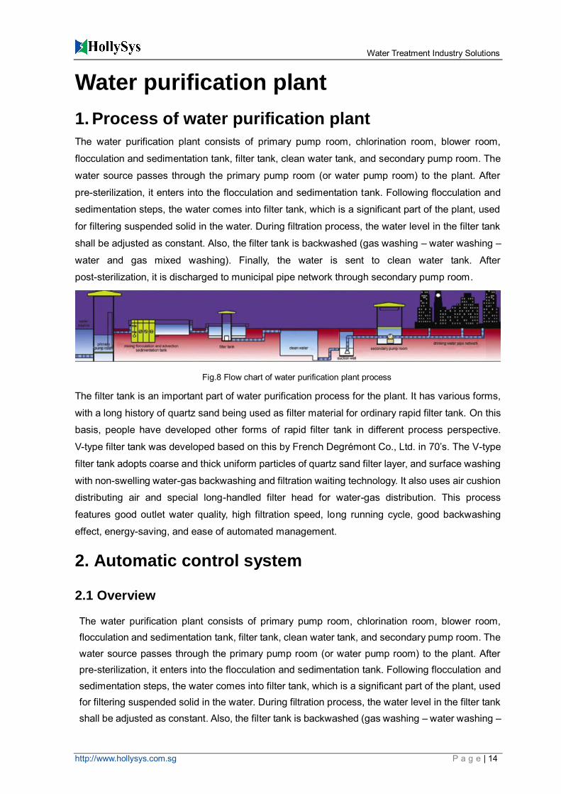
The water purification plant consists of primary pump room, chlorination room, blower room,
flocculation and sedimentation tank, filter tank, clean water tank, and secondary pump room. The
water source passes through the primary pump room (or water pump room) to the plant. After
pre-sterilization, it enters into the flocculation and sedimentation tank. Following flocculation and
sedimentation steps, the water comes into filter tank, which is a significant part of the plant, used
for filtering suspended solid in the water. During filtration process, the water level in the filter tank
shall be adjusted as constant. Also, the filter tank is backwashed (gas washing – water washing –
water and gas mixed washing). Finally, the water is sent to clean water tank. After
post-sterilization, it is discharged to municipal pipe network through secondary pump room.
The filter tank is an important part of water purification process for the plant. It has various forms,
with a long history of quartz sand being used as filter material for ordinary rapid filter tank. On this
basis, people have developed other forms of rapid filter tank in different process perspective.
V-type filter tank was developed based on this by French Degrémont Co., Ltd. in 70’s. The V-type
filter tank adopts coarse and thick uniform particles of quartz sand filter layer, and surface washing
with non-swelling water-gas backwashing and filtration waiting technology. It also uses air cushion
distributing air and special long-handled filter head for water-gas distribution. This process
features good outlet water quality, high filtration speed, long running cycle, good backwashing
effect, energy-saving, and ease of automated management.
2. Automatic control system
2.1 Overview
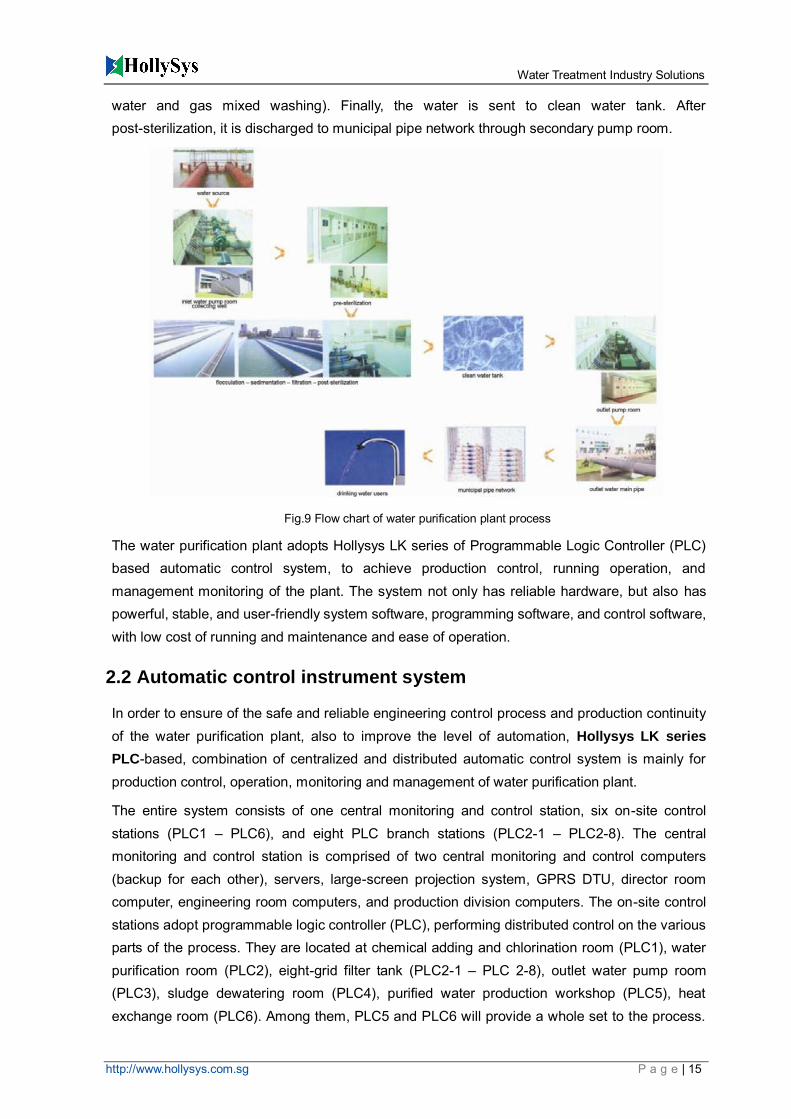
The water purification plant consists of primary pump room, chlorination room, blower room, flocculation and sedimentation tank, filter tank, clean water tank, and secondary pump room. The water source passes through the primary pump room (or water pump room) to the plant. After pre-sterilization, it enters into the flocculation and sedimentation tank. Following flocculation and sedimentation steps, the water comes into filter tank, which is a significant part of the plant, used for filtering suspended solid in the water. During filtration process, the water level in the filter tank shall be adjusted as constant. Also, the filter tank is backwashed (gas washing – water washing –
Fig.8 Flow chart of water purification plant process
Water Treatment Industry Solutions
http://www.hollysys.com.sg P a g e | 15
water and gas mixed washing). Finally, the water is sent to clean water tank. After post-sterilization, it is discharged to municipal pipe network through secondary pump room.
The water purification plant adopts Hollysys LK series of Programmable Logic Controller (PLC) based automatic control system, to achieve production control, running operation, and management monitoring of the plant. The system not only has reliable hardware, but also has powerful, stable, and user-friendly system software, programming software, and control software, with low cost of running and maintenance and ease of operation.
2.2 Automatic control instrument system
In order to ensure of the safe and reliable engineering control process and production continuity of the water purification plant, also to improve the level of automation, Hollysys LK series
PLC-based, combination of centralized and distributed automatic control system is mainly for production control, operation, monitoring and management of water purification plant.
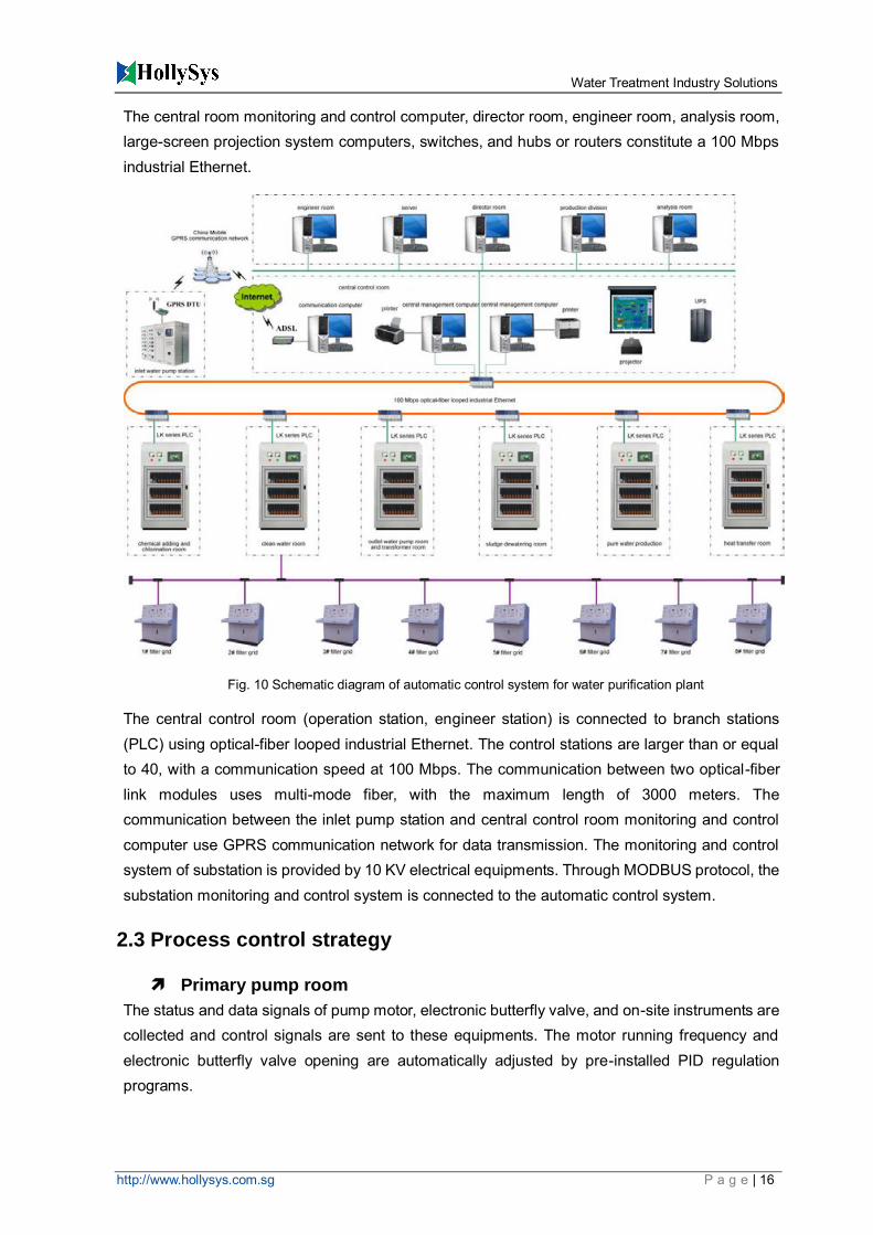
The entire system consists of one central monitoring and control station, six on-site control stations (PLC1 – PLC6), and eight PLC branch stations (PLC2-1 – PLC2-8). The central monitoring and control station is comprised of two central monitoring and control computers (backup for each other), servers, large-screen projection system, GPRS DTU, director room computer, engineering room computers, and production division computers. The on-site control stations adopt programmable logic controller (PLC), performing distributed control on the various parts of the process. They are located at chemical adding and chlorination room (PLC1), water purification room (PLC2), eight-grid filter tank (PLC2-1 – PLC 2-8), outlet water pump room (PLC3), sludge dewatering room (PLC4), purified water production workshop (PLC5), heat exchange room (PLC6). Among them, PLC5 and PLC6 will provide a whole set to the process.
Fig.9 Flow chart of water purification plant process
Water Treatment Industry Solutions
http://www.hollysys.com.sg P a g e | 16
The central room monitoring and control computer, director room, engineer room, analysis room, large-screen projection system computers, switches, and hubs or routers constitute a 100 Mbps industrial Ethernet.
The central control room (operation station, engineer station) is connected to branch stations (PLC) using optical-fiber looped industrial Ethernet. The control stations are larger than or equal to 40, with a communication speed at 100 Mbps. The communication between two optical-fiber link modules uses multi-mode fiber, with the maximum length of 3000 meters. The communication between the inlet pump station and central control room monitoring and control computer use GPRS communication network for data transmission. The monitoring and control system of substation is provided by 10 KV electrical equipments. Through MODBUS protocol, the substation monitoring and control system is connected to the automatic control system.
2.3 Process control strategy
Primary pump room
The status and data signals of pump motor, electronic butterfly valve, and on-site instruments are collected and control signals are sent to these equipments. The motor running frequency and electronic butterfly valve opening are automatically adjusted by pre-installed PID regulation programs.
Fig. 10 Schematic diagram of automatic control system for water purification plant
Water Treatment Industry Solutions
http://www.hollysys.com.sg P a g e | 17
Chemical adding and chlorination room
The status and data signals of on-site equipments and instruments are collected and control signals are sent to these equipments and instruments. The operations of chemical adding and chlorination equipments are automatically controlled by automatic control programs.
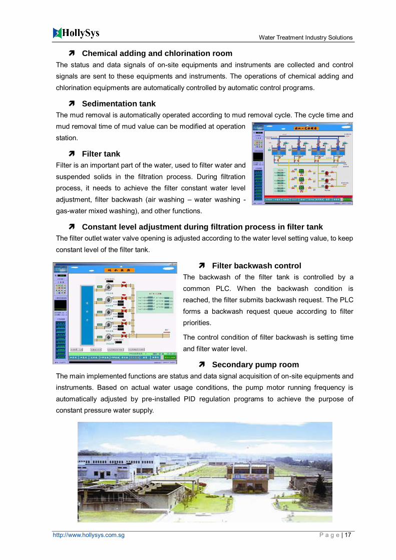
Sedimentation tank
The mud removal is automatically operated according to mud removal cycle. The cycle time and mud removal time of mud value can be modified at operation station.
Filter tank
Filter is an important part of the water, used to filter water and suspended solids in the filtration process. During filtration process, it needs to achieve the filter constant water level adjustment, filter backwash (air washing – water washing - gas-water mixed washing), and other functions.
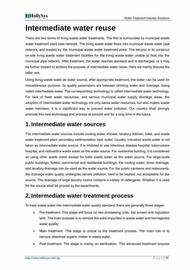
Constant level adjustment during filtration process in filter tank
The filter outlet water valve opening is adjusted according to the water level setting value, to keep constant level of the filter tank.
Filter backwash control
The backwash of the filter tank is controlled by a common PLC. When the backwash condition is reached, the filter submits backwash request. The PLC forms a backwash request queue according to filter priorities.
The control condition of filter backwash is setting time and filter water level.
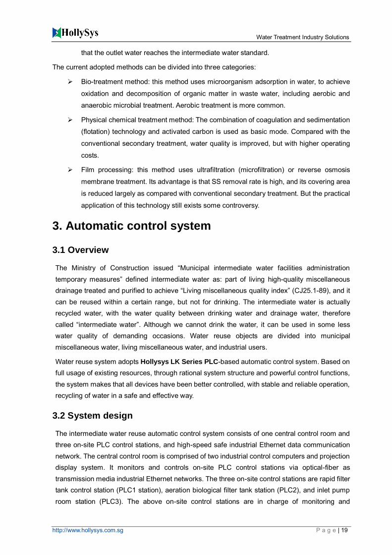
Secondary pump room
The main implemented functions are status and data signal acquisition of on-site equipments and instruments. Based on actual water usage conditions, the pump motor running frequency is automatically adjusted by pre-installed PID regulation programs to achieve the purpose of constant pressure water supply.
Water Treatment Industry Solutions
http://www.hollysys.com.sg P a g e | 18
Intermediate water reuse There are two forms of living waste water treatments. The first is surrounded by municipal waste
water treatment plant pipe network. The living waste water flows into municipal waste water pipe
network, and treated by the municipal waste water treatment plant. The second is to construct
on-site living waste water treatment facilities for the living waste water unable to flow into the
municipal pipe network. After treatment, the water reaches standard and is discharged, or it may
be further treated to achieve the purpose of intermediate water reuse. Here we mainly discuss the
latter one.
Using living waste water as water source, after appropriate treatment, the water can be used for
miscellaneous purpose. Its quality parameters are between drinking water and drainage, being
called intermediate water. The corresponding technology is called intermediate water technology.
For lack of fresh water resources, and serious municipal water supply shortage areas, the
adoption of intermediate water technology not only saves water resources, but also makes waste
water harmless. It is a significant way to prevent water pollution. Our country shall strongly
promote this new technology and process at present and for a long time in the future.
1. Intermediate water sources
The intermediate water sources include cooling water, shower, lavatory, kitchen, toilet, and waste
water treatment plant secondary sedimentation tank outlet. Usually, industrial waste water is not
taken as intermediate water source. It is inhibited to use infectious disease hospital, tuberculosis
hospital, and radioactive waste water as the water source. For residential building, it is considered
as using other waste water except for toilet waste water as the water source. For large-scale
public buildings, hotels, commercial and residential buildings, the cooling water, show drainage,
and lavatory drainage can be used as the water source. For the public canteens and restaurants,
the drainage water quality undergoes severe pollution, hard to be treated, not acceptable for the
source. The drainage of large laundry rooms contains a variety of detergents. Whether it is used
for the source shall be proved by the experiments.
2. Intermediate water treatment process
To treat waste water into intermediate water quality standard, there are generally three stages:
Pre-treatment: This stage will focus on two processing units, bar screen and regulation
tank. The main purpose is to remove the solid impurities in waste water and homogenize
water quality.
Main treatment: This stage is critical to the treatment process. The main role is to
remove dissolved organic matter in waste water.
Post-treatment: The stage is mainly on sterilization. This advanced treatment ensures
Water Treatment Industry Solutions
http://www.hollysys.com.sg P a g e | 19
that the outlet water reaches the intermediate water standard.
The current adopted methods can be divided into three categories:
Bio-treatment method: this method uses microorganism adsorption in water, to achieve
oxidation and decomposition of organic matter in waste water, including aerobic and
anaerobic microbial treatment. Aerobic treatment is more common.
Physical chemical treatment method: The combination of coagulation and sedimentation
(flotation) technology and activated carbon is used as basic mode. Compared with the
conventional secondary treatment, water quality is improved, but with higher operating
costs.
Film processing: this method uses ultrafiltration (microfiltration) or reverse osmosis
membrane treatment. Its advantage is that SS removal rate is high, and its covering area
is reduced largely as compared with conventional secondary treatment. But the practical
application of this technology still exists some controversy.
3. Automatic control system
3.1 Overview
The Ministry of Construction issued “Municipal intermediate water facilities administration temporary measures” defined intermediate water as: part of living high-quality miscellaneous drainage treated and purified to achieve “Living miscellaneous quality index” (CJ25.1-89), and it can be reused within a certain range, but not for drinking. The intermediate water is actually recycled water, with the water quality between drinking water and drainage water, therefore called “intermediate water”. Although we cannot drink the water, it can be used in some less water quality of demanding occasions. Water reuse objects are divided into municipal miscellaneous water, living miscellaneous water, and industrial users.
Water reuse system adopts Hollysys LK Series PLC-based automatic control system. Based on full usage of existing resources, through rational system structure and powerful control functions, the system makes that all devices have been better controlled, with stable and reliable operation, recycling of water in a safe and effective way.
3.2 System design
The intermediate water reuse automatic control system consists of one central control room and three on-site PLC control stations, and high-speed safe industrial Ethernet data communication network. The central control room is comprised of two industrial control computers and projection display system. It monitors and controls on-site PLC control stations via optical-fiber as transmission media industrial Ethernet networks. The three on-site control stations are rapid filter tank control station (PLC1 station), aeration biological filter tank station (PLC2), and inlet pump room station (PLC3). The above on-site control stations are in charge of monitoring and
Water Treatment Industry Solutions
http://www.hollysys.com.sg P a g e | 20
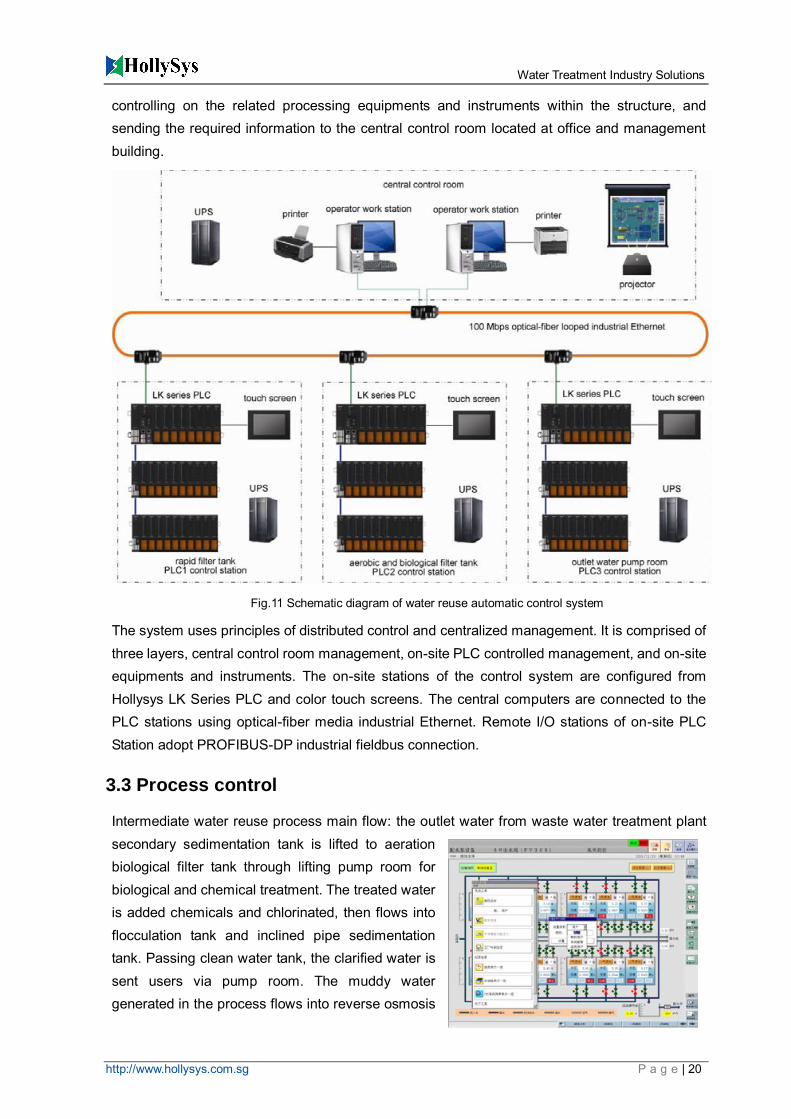
controlling on the related processing equipments and instruments within the structure, and sending the required information to the central control room located at office and management building.
The system uses principles of distributed control and centralized management. It is comprised of three layers, central control room management, on-site PLC controlled management, and on-site equipments and instruments. The on-site stations of the control system are configured from Hollysys LK Series PLC and color touch screens. The central computers are connected to the PLC stations using optical-fiber media industrial Ethernet. Remote I/O stations of on-site PLC Station adopt PROFIBUS-DP industrial fieldbus connection.
3.3 Process control
Intermediate water reuse process main flow: the outlet water from waste water treatment plant secondary sedimentation tank is lifted to aeration biological filter tank through lifting pump room for biological and chemical treatment. The treated water is added chemicals and chlorinated, then flows into flocculation tank and inclined pipe sedimentation tank. Passing clean water tank, the clarified water is sent users via pump room. The muddy water generated in the process flows into reverse osmosis
Fig.11 Schematic diagram of water reuse automatic control system
Water Treatment Industry Solutions
http://www.hollysys.com.sg P a g e | 21
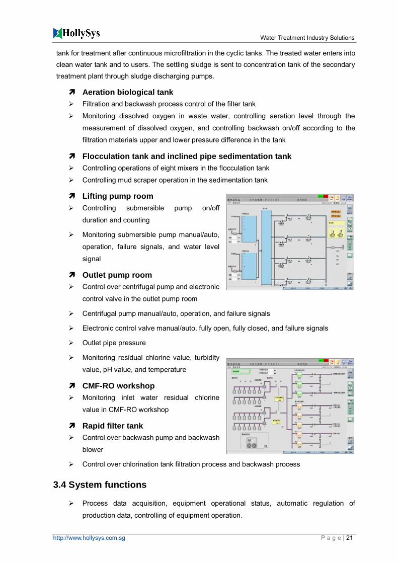
tank for treatment after continuous microfiltration in the cyclic tanks. The treated water enters into clean water tank and to users. The settling sludge is sent to concentration tank of the secondary treatment plant through sludge discharging pumps.
Aeration biological tank
Filtration and backwash process control of the filter tank
Monitoring dissolved oxygen in waste water, controlling aeration level through the
measurement of dissolved oxygen, and controlling backwash on/off according to the
filtration materials upper and lower pressure difference in the tank
Flocculation tank and inclined pipe sedimentation tank
Controlling operations of eight mixers in the flocculation tank
Controlling mud scraper operation in the sedimentation tank
Lifting pump room
Controlling submersible pump on/off
duration and counting
Monitoring submersible pump manual/auto,
operation, failure signals, and water level
signal
Outlet pump room
Control over centrifugal pump and electronic
control valve in the outlet pump room
Centrifugal pump manual/auto, operation, and failure signals
Electronic control valve manual/auto, fully open, fully closed, and failure signals
Outlet pipe pressure
Monitoring residual chlorine value, turbidity
value, pH value, and temperature
CMF-RO workshop
Monitoring inlet water residual chlorine
value in CMF-RO workshop
Rapid filter tank
Control over backwash pump and backwash
blower
Control over chlorination tank filtration process and backwash process
3.4 System functions
Process data acquisition, equipment operational status, automatic regulation of
production data, controlling of equipment operation.
Water Treatment Industry Solutions
http://www.hollysys.com.sg P a g e | 22
Display entire process flow chart, sectional process flow chart, power supply system
diagram, process parameters, electrical equipment operational status, etc., on the color
monitor (TFT).
From the collected data, the system can automatically build database, store process
parameters, electrical equipment status, alarm data, and failure data. It can also
generate trend curve for process parameters. The management operators can analyze
and research the process curve to further improve process operational procedures,
increasing production efficiency.
According to production management requirement, print out yearly, monthly, daily, and
duty operation table, alarm table, failure table, and process flow chart (color copy).
Real-time alarm printing and failure printing.
Communicating with on-site control systems via industrial Ethernet, the computer
system can diagnose a variety of failures online.
Water Treatment Industry Solutions
http://www.hollysys.com.sg P a g e | 23
Municipal pump station
1. Overview In order to reduce operating costs and enhance enterprises’ modern and information level, Hollysys LK series PLC based municipal water supply scheduling pump station monitoring and control system consists of three parts, FacView monitoring and control configuration software, high-speed data communication network (VPN), and PLC system. The concept of the system structure is developed based on an open and modular structure, to enable the system with flexible and easy programming and configuration operations. According to operational requirement of the municipal water supply pump station monitoring and control system, as well as the full consideration of the requirement of high reliability, availability, convenience, maintainability, and scalability of the system, the entire system can achieve real-time, accuracy, integrity, and uniformity on control operation, data acquisition, and information.
2. Monitoring and control system design
2.1 Overall system architecture
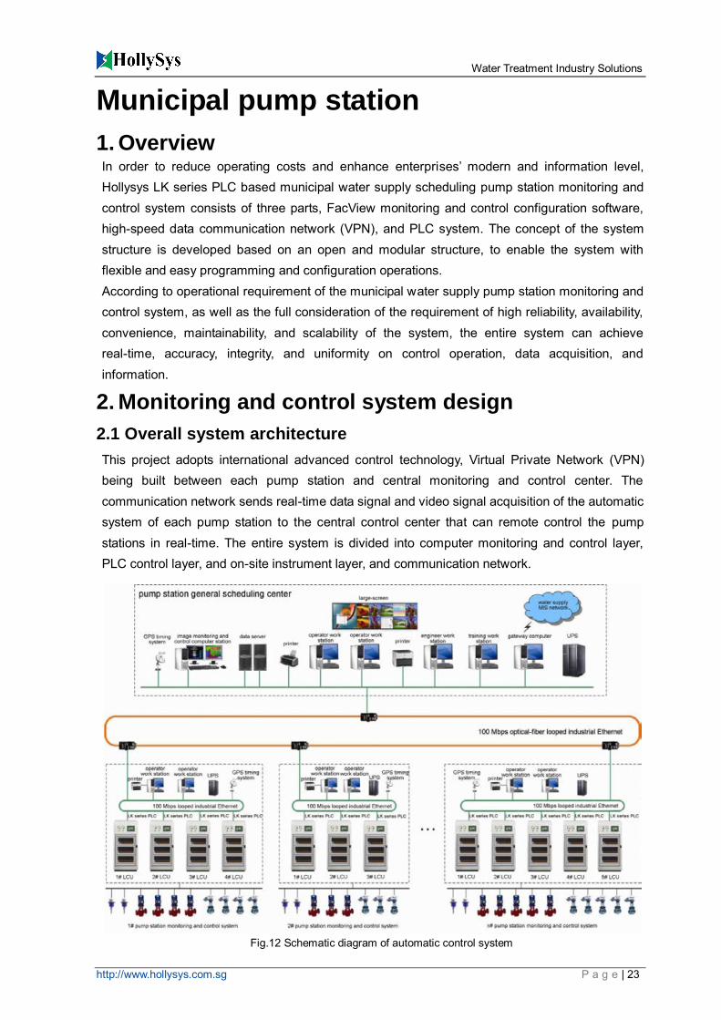
This project adopts international advanced control technology, Virtual Private Network (VPN) being built between each pump station and central monitoring and control center. The communication network sends real-time data signal and video signal acquisition of the automatic system of each pump station to the central control center that can remote control the pump stations in real-time. The entire system is divided into computer monitoring and control layer, PLC control layer, and on-site instrument layer, and communication network.
Fig.12 Schematic diagram of automatic control system

Water Treatment Industry Solutions
http://www.hollysys.com.sg P a g e | 24
Central monitoring and control center (upper-level monitoring and control layer)
The central control center is located in the system central control room. It is the core part of the entire pump station automatic control system, responsible for managing the whole system database and production process scheduling. The on-site control stations send data information to the monitoring and control computer. The system can automatically complete data storage, display, analysis, alarm, and sharing. Also, the central control center and system sub-control center take control of on-site pump station at the same time, and backup for each other.
PLC control station (on-site control layer)
The system has control station at each pump station, responsible for automatic monitoring and control over operation of each on-site pump station. The PLC control station includes control cabinet, LK serious PLC controller, various I/O modules, operation touch screen, and video monitoring device.
On-site instrument layer
On-site instrument layer locates at the bottom of the system, being the data source for the system. It includes various instruments for on-site data acquisition, responsible for data acquisition, display, alarm, and sending to PLC control station and central monitoring and control center.
Data sharing and safety
The system communication network is the key part to achieve unity, stability, safety, and integrity of the system, as well as the basis of the system functions. For this application, our company adopts Virtual Private Network (VPN) to form a virtual local area network (LAN) connecting each pump station and monitoring and control center. The pump station using this network can achieve data sending/receiving and monitoring and control image transmission.
2.2 Pump station control strategy
The pump station has several submersible pumps, with work/variable frequency switching control. The pump control devices are equipped with three modes, manual, automatic, and central, for the purpose of on-site manual control, PLC system automatic control, and remote control from central control room. All the starting devices of the pumps are equipped with over-voltage and overload protection, enable safe and stable operation of the pumps.
Pump operation control
Pump units is operating alternatively, to make sure that each pump running time is
approximately the same, and no single pump running for a long time.
Control modes: manual, automatic, and remote
Water Treatment Industry Solutions
http://www.hollysys.com.sg P a g e | 25
Variable frequency constant water level control strategy
Control during maintenance of frequency transformer cabinet
Pump special control
When the system detects one of these that the water level is lower the minimum limit or the pump is overheated, overloaded, over-voltage, phase lack, or frequency transformer failure, it will mandatorily start or stop the pump.
Bar screen machine control
The operation of bar screen machine is controlled by PLC setting time. That is, a time cycle is set inside the PLC (time cycle can be set using touch screen or remotely). According to this time cycle, bar screen machine clear the screening periodically.
Electronic valve control
Under any control modes, the electronic value must be controlled to open, close, and stop.
On/off control
The machine can be turned on/off according to the water level of the water collecting basin, to control waste water flow. It can be manually, touch-screen controlled, or remotely controlled by the central control room to open, close, and stop the electronic valve. Also, the electronic valves can be remotely controlled under automatic control mode.
Communication failure control
When the PLC system is disconnected from the communication with the central monitoring and control system, the PLC system automatically converts to on-site automatic control, ensuring that the pump control system is normally operating under unmanned condition.
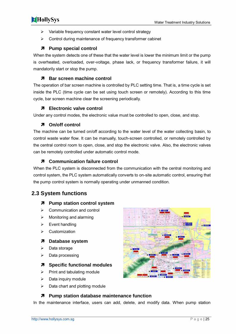
2.3 System functions
Pump station control system
Communication and control
Monitoring and alarming
Event handling
Customization
Database system
Data storage
Data processing
Specific functional modules
Print and tabulating module
Data inquiry module
Data chart and plotting module
Pump station database maintenance function
In the maintenance interface, users can add, delete, and modify data. When pump station

Water Treatment Industry Solutions
http://www.hollysys.com.sg P a g e | 26
number increases, user can easily add the new pump stations to the database.
User management function
Image system
Information sharing
The running information of the monitoring and control system, pump station data management system, and image system can be provided to various functional divisions of the plant, managers and decision-makers, and other different authorization levels of department or personnel via Intranet network.
Management Assisting
The pump station data management system can provide historical data recordings to managers, enabling them to make dynamic analysis on the local pump station operation status. This also provide basis for decision makings.
3. Features and advantages
A solution integrated from on-site data, off-site data, and disaster recovery can
guarantee data consistency in the maximum degree.
Support two modes of disaster recovery, homogeneous and heterogeneous structure.
The disaster recovery level increases in turn, the latter being based on the former
It can be implemented step by step. The later investment protects earlier one.
It can support manual/automatic disaster recover solution. User can freely select as
needed.
图 1 水煤浆
工艺流程图
图 1 水电站
自动化控制系
统图
图 1 泵站监控
系统结构图
图 1 闸门自
动化控制系统
图
图 1 油田计量
工艺流程图
图 1 盐化厂自
控系统图
图 2 凝结水精
处理工艺流程
图
图 1 除灰除
渣自动化控制
系统图
图 1 ETS 系
统示意图
图 2 系统网络
结构示意图
电 力
冶 金
化 工
水利
交 通
市 政
能 源
环保
建 材
汽 车
机 械
食品
制 药
造 纸
纺
织 …
…
纺 织
印 刷
矿山 ……
图 2 系统网络
结构示意图
调度控制中心
系统配置图
图 1 化学水
处理自控系统
示意图
站控系统配置
图
图 2 输煤系
统工艺流程示
意图
图 1 输煤程
控系统结构图
图 5 除灰系统
流程图
图 4 除渣系统
流程图
图 3 锅炉补给
水 处 理 系 统
(化学除盐)
流程图
天然气长输管
道 SCADA 系
统配置图
图 1 系统网络
结构示意图
图 1 系统网络
结构示意图
图 1 车辆段机
电设备监控系
统结构图
Automation Technology for Better Work, Life and Environment
Beijing HollySys Co., Ltd.
Hangzhou HollySys Automation Co., Ltd.
Beijing HollySys Automation & Drive Co., Ltd.
No. 2, Disheng Middle Road
Economic-Technological Development Area
100176, Beijing, P.R. China
http://www.hollysys.com
International Business
HollySys (Asia Pacific) Pte Ltd
200 Pandan Loop, #08-01
Pantech 21, Singapore 128388
Tel: +65 6777-0950
Fax: +65 6777-2730
http://www.hollysys.com.sg