Water System Design - CRgov.com
85
Published by the Town of Castle Rock, 100 N. Wilcox St., Castle Rock, CO 80104 December 4, 2018 T O W N O F C A S T L E R O C K Water System Design 2018 CRITERIA MANUAL
Transcript of Water System Design - CRgov.com

Published by the Town of Castle Rock, 100 N. Wilcox St., Castle Rock, CO 80104 December 4, 2018
T O W N O F C A S T L E R O C K
Water System Design
2018 CRITERIA MANUAL

1
TABLE OF CONTENTS Chapter 1. GENERAL PROVISIONS
1.1 Introduction…………………………………………………………………………………… 7
1.2 Jurisdiction………………………………………………………………………………….... 7
1.3 Purpose………………………………………………………………………………………. 7
1.4 Amendments and Revisions……………………………………………………………….. 7
1.5 Enforcement Responsibility………………………………………………………………… 8
1.6 Review and Acceptance…………………………………………………………………….. 8
1.7 Interpretation…………………………………………………………………………………. 8
1.8 Relationship to Other Standards…………………………………………………………… 9
1.9 Variances from these Criteria………………………………………………………………. 9
1.10 Supplemental Information to these Criteria……………………………………………….. 9
1.11 Acronyms………………………………………………………………………………..…… 10
1.12 Definitions of Terms………………………………………………………………………… 12
1.13 References…………………………………………………………………………………… 15
Chapter 2. WATER SYSTEM POLICIES
2.1 Introduction………………………………………………………………………………....... 16
2.2 Planning Policy………………………………………………………………………………. 16
2.3 Design Policy…………………………………………………………………………………. 16
2.4 Construction of Public Improvements Policy……………………………………………… 16
2.5 Ownership of Public Improvements Policy………………………………………………… 17
2.6 Operations and Maintenance Policy……………………………………………………..... 17
2.7 Policy Regarding Pressure and/or Continuous Flow…………………………………….. 17
2.8 Regulatory and Legal Policy…………...…………………………………………………… 18
2.9 Hazard Minimization and Public Safety Policy……………………………………………. 18
Chapter 3. WATER SYSTEM SUBMITTAL REQUIREMENTS
3.1 Introduction…………………………………………………………………………………… 19

2
3.2 Review Process………………………………………………………………………………… 19
3.2.1 Pre-Application Consultation……………………………………………………… .. 19
3.2.2 Utility Report Requirements………………………………………………………… 19
3.2.2.1 Format………………………………………………………………………. 20
3.2.2.2 Checklists…………………………………………………………………… 20
3.2.2.3 Approval Block………………………………………………………………20
3.2.2.4 Stand-Alone Document……………………………………………………. 20
3.2.2.5 Combined Reports…………………………………………………………. 20
3.2.2.6 Submittal Adequacy……………………………………………………….. 21
3.2.3 Review by Referral Agencies………………………………………………………. 21
3.3 Acceptance…………………………………………………………………………………… 21
3.3.1 Final Utility Report Required for Construction……………………………………. 21
3.3.2 One Year Approval Limitation for Final Utility Report……………………………. 21
3.4 Concept Water Utility Letter………………………………………………………………… 21
3.4.1 PDP Water Utility Information………………………………………………........... 23
3.4.2 Castle Rock Water Responsibility………………………………………………….. 24
3.5 Preliminary Water Utility Report……………………………………………………............ 24
3.5.1 SDP Water Utility Plan………………………………………………………………. 29
3.5.2 Castle Rock Water Responsibility…………………………………………………. 30
3.6 Final Water Utility Report…………………………………………………………………… 30
3.6.1 Disclaimer…………………………………………………………………………….. 37
3.7 Construction Drawings………………………………………………………………………. 37
3.7.1 Water System Improvements………………………………………………............ 37
3.7.2 Indemnification Statement…………………………………………………………... 37
3.7.3 Construction Drawing Requirements………………………………………………. 37
3.7.3.1 Utility Construction Drawings for Water System Improvements………. 38
3.8 Record Drawings……………………………………………………………………….……..40
Chapter 4. WATER SYSTEM DESIGN CRITERIA
4.1 Reference Design Documents…………………………………………………………….. 41
4.2 Prohibited Installations……………………………………………………………………… 41
4.3 Unlawful Connections………………………………………………………………………. 42

3
4.4 Minimum Water System Design Criteria…………………………………………..………. 42
4.4.1 Design Demands…………………………………………………………………….. 43
4.4.1.1 Water System Average Daily Demands (ADD)…………………………. 44
4.4.1.2 Demand Factors………………………………………………………….. ...44
4.4.1.3 Fire Flows…………………………………………………………………… 44
4.4.2 Storage Requirements………………………………………………………………. 45
4.4.3 Minimum Hydraulic Performance Criteria…………………………………………. 45
4.4.3.1 Operating Pressures and Pressure Zone Characteristics….………. ..46
4.4.3.2 Assumed Pressures at Existing System Connections…………………46
4.4.3.3 Maximum Velocities and Headlosses……………………………………47
4.4.4 General Water System Layout Criteria……………….….………………………… 47
4.4.4.1 Location…………………………………………………………………… 47
4.4.4.2 Horizontal Layout…………………..…………………………………….. 48
4.4.4.3 Vertical Layout…………………………………………………………… 48
4.4.5 Pipe Joint Deflection………………………………………………………………… 49
4.4.6 Distribution Main Looping……………………………………………………….….. 49
4.4.7 Transmission Mains…………………………………………………………………. 50
4.4.8 Utility Crossings……………………………………………………………………… 50
4.4.8.1 Water Main Crossing Over a Sanitary Sewer Main……………………. 51
4.4.8.2 Water Main Crossing Under a Sanitary Sewer Main……….…………. 51
4.4.8.3 Water Main Crossing Over a Storm Sewer……………………………… 51
4.4.8.4 Water Main Crossing Under a Storm Sewer……………………………..52
4.4.8.5 Limits on Minimum Vertical Clearance……………………………………52
4.4.9 Bored Crossings……………………………………………………………………… 52
4.4.10 Appurtenances………………………………………………………………………. 53
4.4.10.1 Valves……………………………………………………………………. 53
4.4.10.2 Pressure Reducing Valves…………………………………………….. 54
4.4.10.3 Fire Hydrants……………………………………………………………. 54
4.4.10.4 Thrust Restraint……………………………………………………….. .. 55
4.4.10.5 Meters……………………………………………………………………. 55
4.4.10.6 Fire Protection Service Lines………………………………………….. 56
4.4.10.7 Manholes………………………………………………………………… 57
4.4.10.8 Backflow Prevention Assemblies……………………………………… 57

4
4.4.10.9 Booster Pumps………………………………………………………… 57
4.4.10.10 Combination Air Release and Vacuum Valves…………………….. 58
4.4.10.11 Blow-off Pumping Manholes…………………………………………. 58
4.4.10.12 Tracer Wire and Warning Tape……………………………………… 58
4.4.11 Fill Areas……………………………………………………………………………. 58
4.4.12 Trail Access………………………………………………………………………… 58
4.4.13 Main Break Swale Design………………………………………………………… 59
4.4.14 Future Connections…………………………………………………………………59
4.4.15 Water Service Lines……………………………………………………………….. 59
4.4.15.1 Ownership………………………………………………………………. 60
4.4.15.2 Layout…………………………………………………………………… 60
4.5 Easements………………………………………………………………………………….. 61
4.6 Utility Easement Note Required on Plats……………………………………….............. 62
Chapter 5. PUMP STATION DESIGN CRITERIA 5.1 General………………………………………………………………………………………. 63
5.1.1 Scope……………………………………………………………………………….. 63
5.1.2 Castle Rock Water Review and Approval…………………………………….. 63
5.1.3 Relationship to Other Standards…………………………………………………. 63
5.1.4 Reference Design Documents……………………………………………………. 63
5.1.5 Location………………………………………………………………………………63
5.1.6 Flood Protection……………………………………………………………………. 64
5.1.7 Accessibility and Security…………………………………………………………. 64
5.2 Minimum General Pump Station Design Criteria……………………………………….. 64
5.3 Pump Station Conditional Design Criteria…………….………………………………… 65
5.4 Pumps………………………………………………………………………………………. 66
5.5 Electric Pump Motors……………………………………………………………………… 66
5.5.1 Applicable Industry Standards……………………………………………………. 66
5.5.2 Voltage and Current……………………………………………………………….. 66
5.5.3 Operating Temperature and Insulation Classification………………………….. 66
5.5.4 Enclosure and Cooling…………………………………………………………….. 67
5.5.5 Bearings…………………………………………………………………………….. 67

5
5.5.6 Service Factor……………………………………………………………………… 67
5.6 Standby Power or Generator…………………………………………………………….. 67
5.7 Site Improvements…………………………………………………………………………. 67
5.7.1 Property……………………………………………………………………………... 67
5.7.1.1 Property Dedication……………………………………………........... 67
5.7.1.2 Site Configuration……………………………………………………… 68
5.7.2 Site Amenities………………………………………………………………………. 68
Chapter 6. WATER STORAGE TANK DESIGN CRITERIA 6.1 General……………………………………………………………………………………… 70
6.1.1 Scope and Approval………………………………………………………………. 70
6.1.2 Relationship to Other Standards…………………………………………………. 70
6.1.3 Reference Design Documents……………………………………………………. 70
6.1.4 Location………………………………………………………………………………70
6.1.5 Accessibility and Security…………………………………………………………. 70
6.2 Minimum Water Storage Tank Design Criteria…………………………………………. 71
6.2.1 General Design Criteria…………………………………………………………… 71
6.2.2 Cleaning and Drainage…………………………………………………………… 71
6.3 Site Improvements………………………………………………………………………… 71
6.3.1 Property………………………………………………………………………………71
6.3.1.1 Property Dedication……………………………………………………….71
6.3.1.2 Site Configuration…………………………………………………………72
6.3.2 Site Amenities……………………………………………………………………….72
Chapter 7. WELL SITE CRITERIA 7.1 General………………………………………………………………………………………. 74
7.1.1 Scope and Approval……………………………………………………………….. 74
7.1.2 Relationship to Other Standards…………………………………………………. 74
7.1.3 Reference Design Documents……………………………………………………..74
7.1.4 Flood Protection……………………………………………………………………..75
7.1.5 Accessibility and Security…………………………………………………………..75
7.2 Well Site Criteria……………………………………………………………………………. 75
6
7.2.1 Property Information……………………………………………………………….. 75
7.2.2 Minimum Well Site Size…………………………………………………………… 76
7.2.3 Site Location Considerations…………………………………………………….. . 77
7.2.4 Building Material Requirements……………………………………………………77
7.2.5 Site Amenities………………………………………………………………………. 77
Chapter 8. SUPERVISORY CONTROL AND DATA ACQUISITION SYSTEM (SCADA) 8.1 General………………………………………………………………………………………78
8.1.1 Scope ………………………………………………………………………………..78
8.1.2 Purpose and Rationale of the SCADA System…………………………………. 78
8.2 General Design Criteria…………………………………………………………………….78
8.2.1 Design Responsibility……………………………………………………………….78
8.2.2 Programming………………………………………………………………………...79
8.2.3 Base Standards to be Met………………………………………………………… 79
8.3 Minimum Facility Design Requirements…………………………………………………. 79
8.3.1 General……………………………………………………………………………….79
8.3.2 Pump Station SCADA……………………………………………………………… 80
8.3.3 Water Storage Tank SCADA……………………………………………………… 81
8.3.4 Well Facility SCADA……………………………………………………………….. 81
Chapter 9. WATER PURIFICATION FACILITIES DESIGN CRITERIA 9.1 General……………………………………………………………………………………… 83
9.1.1 Scope and Approval……………………………………………………………….. 83
9.1.2 Relationship to Other Standards ………………………………………………… 83
9.1.3 Minimum Design Considerations…………………………………………………. 83

7
Chapter 1 – General Provisions
1.1 Introduction
These criteria and design standards together with all future amendments shall be known as the Town of Castle Rock Water System Design Criteria Manual (hereafter called “Criteria”). All utility reports and plans, analyses, and designs, submitted as a requirement of the Town of Castle Rock Regulations (hereafter called “Regulations”), shall comply with these Criteria.
1.2 Jurisdiction
These Criteria shall apply to all land within the incorporated area of the Town of Castle Rock, or served by the Town, including any public lands. These Criteria shall apply to all systems and facilities constructed in or on Town Rights-of-Way, easements dedicated for utilities across public or private property, easements for public use, and to all privately owned and maintained system facilities.
1.3 Purpose
Presented in these Criteria are the policies and minimum technical criteria for the planning, analysis and design of potable water systems within the boundaries of the Town of Castle Rock and areas served by the Town. Unless otherwise noted, these Criteria shall also apply to raw water systems. All subdivisions, re-subdivisions, Planned Unit Developments, or any other proposed construction submitted for acceptance under the provisions of the Regulations shall include adequate and appropriate water system planning, analysis, and design. Such planning, analysis, and design shall conform with or exceed the Criteria set forth herein. Water system planning, analysis, and design that require policies and technical expertise not specifically addressed in these Criteria shall follow the provisions of the appropriate regulatory entity, which shall include, but not be limited to, those of the Colorado Department of Public Health and Environment (CDPHE).
1.4 Amendments and Revisions
Policies and criteria may be amended as new technology is developed or if experience gained in the use of these Criteria indicates a need for revision. All technical criteria and policy changes must be recommended by the Director of Castle Rock Water. Minor revisions will require the approval of the Director of Castle Rock Water or his designee. All major revisions will require adoption, by Ordinance, of the Town Council following a Public Hearing thereon. The Director of Castle Rock Water shall monitor the performance and effectiveness of these Criteria and will recommend amendments and revisions as needed.

8
EXAMPLES OF MINOR AND MAJOR REVISIONS
MINOR MAJOR
Grammar Policy Changes
Submittal Requirements Technical Criteria Changes
Clarifications
Construction Detail Revisions for clarification, minor modification
1.5 Enforcement Responsibility
Castle Rock Water shall review all water system reports, plans, analyses, and designs, submitted as a requirement of the Regulations, for compliance with these Criteria. The Regulations are enforced by the Town of Castle Rock and authorized representatives.
1.6 Review and Acceptance
The Town shall review all submittals for general compliance with these Criteria. An acceptance by the Town does not relieve the owner, engineer, or designer from the responsibility of ensuring that the design, calculations, plans, specifications, construction, and record drawings are in compliance with these Criteria, as stated in the owner’s and engineer’s certifications, and in compliance with other applicable State and Federal regulations.
The Town may, but is not required to, refer submittals to other agencies that have an interest or responsibility for water system issues. Other review agencies may include Tri- County Health Department, and regional, State, or Federal agencies responsible for water supply, purification, storage, transmission and distribution, and other water related issues.
1.7 Interpretation
In the interpretation and application of these Criteria by the Director of Castle Rock Water, the provisions herein shall be regarded as the minimum requirements for the protection of the public health, safety and welfare of the residents of the Town. These Criteria shall therefore be regarded as remedial and shall be liberally construed to further its underlying purposes.
Whenever a provision of these Criteria and any other provision of the Regulations or any provision in any law, ordinance, resolution, rule or regulation of any kind, contains any requirement(s) covering any of the same subject matter, the requirements that are more restrictive or impose higher standards shall govern, as determined by the Director of Castle Rock Water.
These Criteria shall not abrogate or annul any binding agreements, including

9
Development Agreements and Public Subdivision Improvement Agreements, or any easements, permits, utility reports or construction drawings either recorded, issued, or accepted by the Town prior to the effective date of these Criteria. In the event that there is an alleged or material discrepancy in these Criteria, the Director of Castle Rock Water shall make any final determinations as to the intent and application of these Criteria.
1.8 Relationship to Other Standards
If the CDPHE, Federal Government, or other applicable regulatory agency imposes stricter criteria, standards or requirements than those contained herein, such provisions shall apply, and shall be subsequently incorporated into the Town’s requirements after due process and public hearing(s) to modify the Town’s Regulations and these Criteria.
1.9 Variances from these Criteria
Modifications to these Criteria shall require a formal variance request. Variances from the provisions of these Criteria may be considered on a case-by-case basis for specific applications only, and shall not establish a precedent for any other project or future development. All revisions to these Criteria shall be documented on CDs for construction and inspection purposes and on Record Drawings for operational purposes. All Variances on a project shall be listed on Site Plans (if applicable) and CDs including the Variance Number, description of the Variance, any conditions of approval, and the approval date. Formal requests for variances from the standards, policies or requirements of these Criteria shall be submitted with documentation and justification to the Development Services Project Manager. The variance request and supporting documentation will be reviewed by Castle Rock Water, and the Director of Castle Rock Water or his designee will issue a formal response to the request. Submittal requirements for variances and information regarding the appeals process shall be as established in the Development Procedures Manual.
1.10 Supplemental Information to these Criteria
Supplemental information, forms, checklists, notes, etc., referenced herein, are available on the Town of Castle Rock website (CRgov.com/codecentral) and shall be referenced or submitted in accordance with the requirements set forth in these Criteria. Please contact Castle Rock Water at 720-733-6000 with any questions regarding the downloading of these files. It is the responsibility of the developer and engineer to obtain the latest version of any submitted document, as the Town will periodically update these items.
1. Preliminary and Final Utility Report Checklists 2. Utility Report Approval Block 3. Variance Request Form 4. Engineer’s Cost Opinion Form 5. Drawing and Digital Submittal Requirements Upon Approval of Construction Drawings 6. Development Procedures Manual 7. Construction Methodology and Materials Manual 8. General Construction Drawing Cover Sheet Notes 9. Utility Construction Drawing Notes
10. Standard Construction Details
11. Record Drawing Checklists

10
1.11 Acronyms
As used in the Town’s Water and Wastewater Criteria Manuals, the following acronyms shall apply:
AC Acre ADD Average Day Demand (water) ADF Average Daily Flow (wastewater) AF/YR Acre-Feet per Year ANSI American National Standards Institute APWA American Public Works Association ARV Combination Air Release/Vacuum Valve ASTM American Society for Testing and Materials AWWA American Water Works Association BOP Bottom of Pipe C Hazen-Williams Pipe Roughness Coefficient CD and CDs Construction Drawing(s) CDOT Colorado Department of Transportation CDPHE Colorado Department of Public Health and Environment CFS Cubic Feet per Second CRW Castle Rock Water DA Development Agreement DIP Ductile Iron Pipe DIPRA Ductile Iron Pipe Research Association DRCOG Denver Regional Council of Governments DU Dwelling Unit FDC Fire Department Connection FF Fire Flow FT Feet FPS Feet per Second GESC Grading, Erosion and Sediment Control GPAD Gallons per Acre per Day GPCD Gallons per Capita per Day GPD Gallons per Day GPM Gallons per Minute GPSD Gallons per Student per Day HGL Hydraulic Grade Line HP High Point I/I Infiltration and Inflow IBC International Building Code IFC International Fire Code IMC International Mechanical Code INS Institutional IPC International Plumbing Code IRC International Residential Code ISO Insurance Service Offices LP Low Point Max Maximum Min Minimum MDD Maximum Day Demand MG Million Gallon MGD Million Gallons per Day MJ Mechanical Joint NAVD North American Vertical Datum NEC National Electric Code NEMA National Electrical Manufacturers Association O&M Operation and Maintenance OSHA Occupational Safety and Health Administration

11
OWTS On-Site Wastewater Treatment System PD Planned Development PDF Peak Design Flow or Portable Document Format PDP Planned Development Plan PE Professional Engineer PF Peaking Factor PHD Peak Hour Demand PLS Professional Land Surveyor PRK Park PRV Pressure Reducing Valve PSI Pounds per Square Inch PUD Planned Unit Development PVC Polyvinyl Chloride RCP Reinforced Concrete Pipe ROW Right-of-Way RMF Residential Multi-Family RSF Residential Single-Family SCADA Supervisory Control and Data Acquisition SDP Site Development Plan SEO State Engineer’s Office SF Square-Foot; Square Feet SFE Single Family Equivalent SIA Subdivision Improvement Agreement STD Standard SWPP Source Water Protection Plan TB Thrust Block TCR Town of Castle Rock TOP Top of Pipe VFD Variable Frequency Drive

12
1.12 Definitions of Terms
BACKFLOW PREVENTION ASSEMBLY OR DEVICE shall mean a device accepted or approved by Castle Rock Water as meeting an applicable specification stated or cited in these Design Criteria or as suitable for the proposed use and as approved and accepted by the Colorado Department of Health.
CIVIL CONTRUCTION PERMIT shall mean a permit, including Standard Conditions and Special Conditions as applicable, issued by the Town to construct Public and/or Private Improvements for the Project based on Construction Drawings approved by the Town.
CODE or MUNICIPAL CODE shall mean the Town of Castle Rock Municipal Code, as amended.
CONSTRUCTION DRAWING(S) (CD or CDs) shall mean Construction Drawings prepared by a Professional Engineer licensed in the State of Colorado for the developer and approved by the Town depicting Public and/or Private Improvements to be constructed for the Project.
CONSULTANT ENGINEER shall mean the Professional Engineer retained by the developer responsible for the creation and submission of Utility Reports and Construction Drawings to the Town for approval for the purpose of one-time construction of facilities.
CRITERIA or DESIGN CRITERIA shall mean the design criteria and requirements contained herein for water and wastewater facilities to be constructed in the Town.
CUSTOMER shall mean any person or entity to which the Town provides goods or services.
DESIGN CRITERIA – See CRITERIA.
DETAILS or STANDARD DETAILS shall mean details issued by Castle Rock Water to be used in Construction Drawings. These Details are maintained and periodically updated on the Town’s website.
DEVELOPER shall mean the party or parties desiring to construct Public and/or Private Improvements within Town rights-of-way or easements, securing all required approvals and permits from the Town and other applicable entities, and assuming full and complete responsibility for the Project.
DEVELOPMENT AGREEMENT (DA) shall mean a formal agreement between an Annexor or Master Developer and the Town that comprehensively addresses development conditions and obligations. DEVELOPMENT SERVICES DEPARTMENT shall mean the Town of Castle Rock Development Services Department located at 100 Wilcox Street, Castle Rock, CO 80104.
EASEMENT shall mean the right of the Town to use lands owned by a private party for the purposes of maintenance, access, utilities, drainage or other use, as specified in an

13
agreement between the Town and the private party.
FINAL ACCEPTANCE shall mean the written notification to the developer from the Town, after satisfactory Warranty Period completion, that all Public Improvements are free of defects, and the Town releases the developer from future maintenance obligations.
INITIAL CONVEYANCE AND ACCEPTANCE shall mean the Town's document and process, which initially accepts, for ownership, maintenance and warranty, the Public Improvements identified in the approved Construction Drawings and Improvement Agreement for a specific Project.
MUNICIPAL CODE – See CODE.
OWNER shall mean the person(s) in title to any portion of the Property, according to the records of the Douglas County Clerk and Recorder. The use of the singular “Owner” shall refer to all Owners of the Property.
PLANNED DEVELOPMENT PLAN (PDP) shall mean a development submittal equivalent to a Preliminary PD Site Plan as defined in the Town’s Municipal Code.
PRIVATE IMPROVEMENTS shall mean those improvements not identified as Public Improvements, and which are not generally installed within the Town rights-of-way, easements, or other Town-owned lands.
PROFESSIONAL ENGINEER shall mean an individual currently registered with the Colorado State Board of Registration as a Professional Engineer, practicing engineering in accordance with State law (Title 12, Article 25, Part 1).
PROJECT shall mean the Public or Private Improvements as designated in the approved Construction Drawings to be constructed in conformance with these Design Criteria. The Project is inclusive of any and all Public or Private Improvement Projects for or within the Town, whether Development Projects, Private Utility Projects or Capital Improvement Projects.
PROPERTY shall mean the real property located in Douglas County, Colorado as described in the Development Agreement, Subdivision Improvement Agreement, or legal description of the real property on which the Project is located.
PUBLIC HEARING shall mean a meeting of the Town Planning Commission or the Town Council for the purpose of hearing comments, testimony, recommendations and other responses from Town staff, developers, interested parties and the general public.
PUBLIC IMPROVEMENTS shall mean those public facilities including, but not limited to, pavement, curb and gutter, sidewalk, pedestrian/bike/equestrian paths, storm drain facilities with related appurtenances, culverts, channels, bridges, water distribution, transmission and storage facilities with related appurtenances, wastewater collection
facilities with related appurtenances, water purification facilities, pavement markings/ signage/striping, traffic signals and related appurtenances, and those processes integral to construction of other Public Improvements listed herein, which upon their completion are to

14
be dedicated to the Town for operation and maintenance by the Town and which are installed within the Town rights-of-way, easements, or other Town-owned lands.
REGULATIONS shall mean the Charter, ordinances, resolutions, rules and regulations of the Town, including the Code, and other provisions of all zoning, subdivision and building codes or any other applicable design criteria adopted by the Town, as the same may be amended periodically and applied uniformly throughout the Town.
SHALL means a mandatory requirement or condition, as approved by the Town.
SITE DEVELOPMENT PLAN (SDP) shall mean a development submittal equivalent to a Preliminary Plat, General Site Plan, Final PD Site Plan, and/or Combined Preliminary Plat/ Final PD Site Plan as defined in the Town’s Municipal Code.
STANDARD DETAILS – See DETAILS.
SUBDIVISION IMPROVEMENT AGREEMENT (SIA) shall mean a formal agreement between a developer and the Town, and identifies the Public Improvements required to support the development. The SIA provides assurances that the Public Improvements will be constructed in accordance with established criteria and standards in a timely manner and comprehensively addresses development conditions and obligations. TOWN shall mean the Town of Castle Rock, Colorado, a Home Rule Municipality. TOWN COUNCIL shall mean the governing body of the Town of Castle Rock, Colorado having all the legislative powers and functions and all other powers possessed by the Town and not conferred on others by the Town Charter. CASTLE ROCK WATER shall mean the Town of Castle Rock Water Department located at 175 Kellogg Court, Castle Rock, CO 80109, telephone number 720-733-6000.
DIRECTOR OF CASTLE ROCK WATER shall mean the Director of Water of the Town of Castle Rock or other authorized representative of Castle Rock Water.
VARIANCE REQUEST shall mean a formal request with adequate documentation and justification for a variance from the standards, provisions, policies or submittal requirements set forth in these Design Criteria that meets the requirements in Section 1.9 of these Design Criteria.
WATER MASTER PLAN shall mean the Town of Castle Rock “2006 Water Master Plan” or any updates to this Plan.
WEBSITE shall mean the Town of Castle Rock website at CRgov.com (or more specifically, CRgov.com/codecentral).
15
1.13 References
The most current version of the following codes are adopted as a secondary code to this Water System Design Criteria Manual:
American Water Works Association Manuals, with all amendments
American Public Works Association, Standard Plans, with all amendments
Colorado Department of Public Health and Environment Design Criteria for Potable Water Systems, with all amendments.

16
Chapter 2 – Water System Policies 2.1 Introduction
Provisions for adequate service, water supply, purification, storage, transmission and distribution are necessary to preserve and promote the general health, welfare, and economic well-being of the residents of the Town of Castle Rock. The Town of Castle Rock must provide coordination, review and master planning of the system in order that the integration of each component of the system meets the intent and purpose of the system as a whole.
The development of the Town’s water system is governed by the policies provided below, as facilitated through the implementation of the Criteria contained herein. Water system facilities shall be designed, constructed, and maintained to provide for the health, safety and welfare of the Town and its surrounding areas. These Criteria shall formally implement interim policies that have been updated from time-to-time by Castle Rock Water since the effective date of the previous version.
2.2 Planning Policy All land developed within, and served by the Town of Castle Rock shall receive full site planning and engineering analyses. Utility reports and plans shall be submitted for all new development and redevelopment within the Town’s jurisdiction in conformance with the requirements set forth herein and the provisions stipulated in the Concept, Preliminary and Final Development Packages. Redevelopment shall be defined as any land disturbance or reconstruction that results in a reconfiguration of existing water system facilities or an increase in demands.
During the initial planning stages of the development, a pre-application meeting shall be coordinated with the Town of Castle Rock Development Services Department in accordance with Chapter 3 of these Criteria. The Town has adopted and maintains a Water Master Plan that establishes the requirements of the water system and identifies the required public improvements necessary to provide the intended level of potable water service throughout the Town. Town Council may ratify the Water Master Plan from time-to-time, as necessary to accommodate changes within the Town’s jurisdiction.
2.3 Design Policy
Water system planning and design within the Town shall adhere to the Criteria contained herein, the latest edition of CDPHE Design Criteria for Potable Water Systems, the Denver Basin Rules, the Denver Basin Artificial Recharge Extraction Rules and Acceptance Procedures of the Town of Castle Rock, any applicable Watershed Protection District ordinances, and the latest Water Master Plan prepared for the Town. Prohibited facilities and connections shall be as described in these Criteria.
2.4 Construction of Public Improvements Policy
The construction of improvements for and within the Town shall conform to the Town’s Civil Construction Permit, the Town’s Construction Notes, Standard Details and

17
Construction Methodology and Materials Manual, and shall adhere to all Town, County, State, and Federal regulations applicable to the work. This shall include the acquisition of all necessary permits, which may include, but not be limited to, 404 permitting through the U.S. Army Corps of Engineers, Stormwater Management Plans, Discharge Permits and Construction Dewatering Permits administered by the State, Town Grading, Erosion and Sediment Control (GESC) permits, flood plain development permits, and traffic control permits. At the completion of construction, all permits and service agreements with power companies and any other private utilities shall be transferred into the customer’s name, and shall under no circumstances be transferred to, or held in the name of the Town, unless the Town is the customer.
Any work proposed to take place within existing Town of Castle Rock streets must be reviewed and approved by the Public Works Department. The type of crossing allowed, traffic control, street repair specifications, etc. shall be as determined by Public Works. Prior to placing the facilities into service and initial acceptance by the Town, all construction related provisions required by the Town shall be satisfied, including startup procedures, inspections and testing of the facilities, and receipt of O&M Manuals and Record Drawings. Additionally, all requirements and responsibilities shall be complied with in association with the warranty period as set forth in the Town’s regulations.
2.5 Ownership of Public Improvements Policy
The delineation between Town-owned and privately owned portions of the system and the associated maintenance responsibilities for each, shall be as set forth in the latest editions of the Municipal Code and Standard Details. Upon execution of final acceptance, the water mains and all appurtenant Town-owned facilities shall become the sole property of the Town, and full legal and equitable title thereto shall be vested in the Town free and clear of any liens, claims, or rights of any third party in or to the Public Improvements.
2.6 Operations and Maintenance Policy
The design of all water system facilities within the Town must provide for access and long-term operation and maintenance of the facilities by the Town. Operation and Maintenance manuals associated with all components to be installed as part of the water system shall be provided to the Town with the Record Drawings required in these Criteria, unless otherwise specifically waived by Castle Rock Water.
Utility easements, dedicated tracts and access easements shall be provided for all water system facilities outside of public right-of-way as set forth in these Criteria, or as otherwise required by Castle Rock Water, and shall be adequate for the operation, maintenance and replacement of the facilities.
2.7 Policy Regarding Pressure and/or Continuous Flow
Castle Rock Water is not responsible or liable for damage from any cause whatsoever to service connections, fixtures and water using appliances, and no person is entitled to damages or payment of refunds by reason of temporary or permanent pressure changes or stoppage of the flow of water through the water system. Dirt or debris can enter water lines for any number of reasons under normal operations of the water system and no

18
person is entitled to damages by reason of dirt or debris entering a service connection.
2.8 Regulatory and Legal Policy
The planning, design, construction and maintenance of the Town’s water system facilities shall provide for and facilitate strict conformance with the regulatory and legal policies of the Town of Castle Rock and the CDPHE. In addition to the adherence of Town and CDPHE design criteria, this shall include, without limitation, policies associated with ongoing reporting requirements and documentation, emergency procedures and remediation, public notification requirements, and the training and certification of staff to operate and maintain the Town’s facilities.
2.9 Hazard Minimization and Public Safety Policy
Public safety and the protection of Town staff shall be an essential objective when planning, designing, constructing, operating, and maintaining the Town’s water system facilities. All such facilities shall be designed with careful consideration of the potential hazards associated with the use and long-term operation and maintenance of the facility. The design phase of all projects shall evaluate the health and safety risks associated with the facilities, and shall include appropriate design features to minimize these risks and to adequately protect the general public and Town personnel from the hazards. Equipment for confined space entry in accordance with OSHA and other applicable regulatory agency requirements shall be provided at all Town of Castle Rock facilities, as required. Hatches with fall prevention covers, intermediate platforms, handrails, safety lighting, etc. shall be as required by Castle Rock Water, or any applicable code.

19
Chapter 3 – Water System Submittal Requirements
3.1 Introduction
The requirements presented in this chapter shall be used to aid the engineer or applicant in the preparation of utility reports, modeling evaluations, and Construction Drawings (CDs) for water system facilities. This Chapter applies primarily to submittal requirements for water distribution systems and the associated Criteria provided in Chapter 4. Submittal requirements for pumps, tanks, wells, purification facilities, etc., may differ from those set forth in this Chapter, and will be discussed at the Pre-Application Consultation, as described in the Section that follows. The requirements presented herein are the minimum necessary, and will be used to evaluate the adequacy of all submittals made to the Town.
3.2 Review Process
3.2.1 Pre-Application Consultation
A pre-application consultation with the Town of Castle Rock Development Services Department is strongly encouraged for any type of development or redevelopment. The purpose of this meeting is to discuss general information about the project, pertinent aspects of the Criteria, the required scope of the utility reports, and any special procedures, analyses, and submittal requirements that may be applicable. The contact phone number for the Town Development Services Department is 720-733-2200.
3.2.2 Utility Report Requirements
Different levels of utility reports shall be included with each of the submittals required by the Town of Castle Rock Development Services Department. The first of the three utility reports shall be the Concept Utility Letter, which shall be submitted in conjunction with the Planned Development Plan (PDP). The purpose of the Concept Utility Letter is to provide sufficient information to determine the adequacy and ability of the Town’s water system to serve the proposed development.
Once the PDP has been approved, a subsequent Preliminary Utility Report shall be submitted in conjunction with the Site Development Plan (SDP). The purpose of the Preliminary Utility Report is to establish preliminary locations and preliminary sizing for the proposed mains, connections and necessary infrastructure extensions, and to set forth the design parameters and sizing criteria for all other appurtenant water facilities required to serve the proposed development.
Upon approval of the SDP and completion of the final utility system designs, a Final Utility Report shall be submitted in conjunction with the Final Construction Documents. The purpose of the Final Utility Report is to provide all final design information and calculations necessary to support the proposed water improvements. The Construction Documents shall include, among other

20
requirements, the submittal of Construction Drawings (CDs), Final Utility Report, Opinion of Estimated Costs, easements by separate document, signed variances, and the Final Plat.
Once approved, the Construction Documents will enable the developer to move forward with the acquisition of the necessary permits for the project.
3.2.2.1 Format
All required reports shall be in Portable Document Format (PDF). The pages within the reports shall be prepared on 8½" x 11” PDF pages. The reports shall follow the format contained in the report checklists. Supporting drawings, figures, and tables may be prepared on 11” x 17” PDF pages. Reports shall include a narrative presenting the project for review in accordance with the information presented in these Criteria, and the requirements established by the Town for the appropriate submittal. One electronic PDF file shall be transmitted to the Development Services Project Manager in conjunction with each required submittal. Paper copies are not required unless specifically requested.
3.2.2.2 Checklists
Report checklists are available on the Town of Castle Rock website (CRgov.com/codecentral), and must be completed and submitted with each utility report. Appropriate notations shall be provided with the checklist to assist the reviewer in determining whether the report is complete. For example, if a specific item is not addressed or not applicable, an explanation needs to be provided.
3.2.2.3 Approval Block
The Concept Utility Letter shall be signed and sealed by a Professional Engineer licensed in the State of Colorado. The Preliminary and Final Utility Reports shall be certified by a Professional Engineer licensed in the State of Colorado and signed by the owner using the approval block sheet available on the Town’s website. The signed approval block shall be in the report behind the title sheet.
3.2.2.4 Stand-Alone Document
Utility reports shall be stand-alone documents. When references are made or assumptions are based on previously submitted reports, the reports must include the appropriate excerpts, pages, tables, and maps containing the referenced information. Assumptions made in previous reports must be verified and substantiated in subsequent reports. Reports shall be legible, or a resubmittal will be required.
3.2.2.5 Combined Reports
Whenever possible, water and wastewater utility reports should be combined into

21
a single document provided that separate sections clearly identify the information associated with each of the two systems.
3.2.2.6 Submittal Adequacy
Any report with incomplete or missing information shall result in the report being returned without review. The Town reserves the right to require additional information beyond that specifically required in these Criteria.
3.2.3 Review by Referral Agencies
The review and approval of the project by State, Federal, and local agencies other than the Town, shall be the responsibility of the developer. The developer shall be required to address all referral agency comments, and to have such comments incorporated into the applicable utility report and plans submitted to the Town.
3.3 Acceptance
3.3.1 Final Utility Report Required for Construction
The Final Utility Report shall conform to the CDs to be used to bid the project, and shall be approved by Castle Rock Water prior to the construction of any water system improvements. A Preliminary Utility Report will not be an acceptable substitute for a Final Utility Report, even if the project has not fundamentally changed from that proposed in the Preliminary Utility Report.
3.3.2 One Year Approval Limitation for Final Utility Report
The approval of the Final Utility Report shall expire simultaneously with the expiration of the approval of the CDs, unless extended in conformance with the provisions of the Municipal Code. At the time the approval of the Final Utility Report expires, the report shall be deemed invalid and a resubmittal will be required. In order to be re-approved, it must be demonstrated that the concepts, designs, and calculations presented in the report are consistent with the Town’s current Criteria. The Concept Utility Letter and the Preliminary Utility Report are not subject to the one-year acceptance period.
3.4 Concept Water Utility Letter
The Concept Water Utility Letter shall be signed and sealed by a Professional Engineer licensed in the State of Colorado. The following outline sets forth the required minimum content to be provided in the Concept Water Utility Letter that shall be submitted with the PDP:
I. PROJECT INFORMATION
A. Name of Project, including legal name of development B. Address C. Owner
22
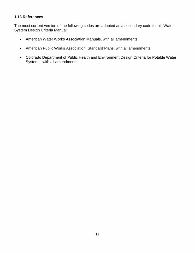
D. Developer E. Engineer F. Submittal date and revision dates as applicable
II. PROJECT LOCATION AND DESCRIPTION
A. Site Location 1. Site Vicinity Map 2. Township, Range, Section, and ¼ Section 3. Streets, Roadways, and Highways adjacent to the proposed development 4. Names of surrounding or adjacent developments
B. Description of Property and Land Use
1. Total area in acres 2. Total number of SFEs proposed for the overall development at build-out
based upon proposed site zoning calculated by utilizing the table in Section 4.4.1 of these Criteria
3. Area (acres) and land use for all parcels to be served within the development boundaries
4. Navigable waterways, major and minor drainageways and flood- plains 5. Existing irrigation canals or ditches 6. Significant geologic features and topography 7. Existing On-Site Wastewater Treatment System (OWTS) 8. Existing water wells
III. EXISTING WATER SYSTEM
A. Existing Distribution System
1. Discuss the existing transmission and distribution lines in the vicinity of the development, including sizes and location that will serve the proposed development.
2. Discuss existing pressures at the proposed connection points to the existing water system.
B. Existing Supply Facilities
1. Identify existing pump stations, wells, PRVs, storage reservoirs, purification facilities, etc., that will serve the development.
2. Describe how service to the proposed development area was addressed in the Water Master Plan.
3. Identify the existing or master-planned pressure zone(s) that encompass the proposed development.
IV. PROPOSED WATER SYSTEM
A. Proposed Distribution System
1. Provide a general overview of the anticipated distribution system layout, and discuss any extensions from the site to the existing water system necessary to serve the development parcels as shown on the PDP. Include a statement that “Any future development of the existing water infrastructure needed to serve this
23
site is the responsibility of the developer.” 2. Discuss looping, as required by Castle Rock Water to service the development
parcels shown on the PDP. Also, generally discuss that internal looping of the site will be provided with the final design, in conformance with the Town’s requirements.
3. The proposed facilities shall conform to the Town’s Water Master Plan unless otherwise approved by variance; therefore, identify any proposed facilities that are not consistent with the Master Plan. If the proposed SFEs exceed the number used in the Town’s Water Master Plan hydraulic modeling, then include additional information on what Improvements this project will need (either on-site or off-site) to show that the system will be able to handle this higher proposed SFE demand.
4. Identify any assumptions made in the Town’s Water Master Plan regarding the proposed development area that may need to be reevaluated in order to serve the development.
B. Proposed Supply Facilities
Discuss any anticipated pump stations, wells, PRVs, storage reservoirs, purification facilities, etc., that will likely be required to adequately serve the development.
V. REFERENCES
Reference all criteria, master plans, reports, or other technical information utilized in the Concept Water Utility Letter.
VI. APPENDICES
Report appendices shall include, but not be limited to, the following items: A. Copies of all pertinent information from reference materials B. Vicinity Map C. Planned Development Plan (PDP) as described in Section 3.4.1 D. Utility Map(s) provided by Castle Rock Water
3.4.1 PDP Water Utility Information
The purpose of the PDP Water Utility Information is to confirm that the utilities proposed for the development can be feasibly connected to the Town’s water distribution system, that the Town’s system can adequately support the development, and to ensure consistency with the Town’s Water Master Plan. In addition to the general formatting and information to be included on all sheets of a PDP required by the Planned Development Plan Submittal Checklist found on the Town’s website, the following information shall be included on the PDP:

24
1. The locations and sizes of all existing major utility lines and appurtenances
(water, sanitary, stormwater, etc.) on and adjacent to the site 2. The location of all existing water wells and On-Site Wastewater Treatment
System (OWTS) on and adjacent to the site 3. The proposed tie-ins to the existing water distribution system, including sizes of
existing mains
3.4.2 Castle Rock Water Responsibility
If Castle Rock Water determines that the Concept Water Utility Letter meets the requirements set forth in Section 3.4 of this Criteria and adequate water rights are conveyed to the Town, the Town will provide water at the designated tie-in points at static pressures to be provided at the conclusion of the review of the Concept Water Utility Letter. Castle Rock Water is not responsible or liable for assumptions made by the developer regarding utility information associated with the proposed development.
3.5 Preliminary Water Utility Report
For the Preliminary Water Utility Report, information contained in the Concept Water Utility Letter shall be updated to reflect the latest projections for land use and densities. Hydraulic modeling shall be required for the site proposed in the SDP. Castle Rock Water may request further hydraulic modeling beyond the site proposed in the SDP, if Castle Rock Water needs more information to confirm the Town’s ability to serve the development. This modeling may be waived on a case-by-case basis at the discretion of Castle Rock Water if the SDP is for a commercial structure on a single lot, with a fire flow no greater than 1500 GPM. The modeling shall accurately reflect the sizes and locations of all proposed water mains associated with the SDP layout. In addition to providing updated land use and density information, the following items shall be specifically addressed:
Further analysis of any concerns raised in the Concept Utility Letter regarding
the Town’s ability to serve the development
Updated discussion of appurtenant water facilities other than distribution mains that will be necessary to serve the development, and the principal design parameters that will be utilized in the final design of such facilities
Status of any variances that have been obtained, or will be pursued
Updated discussion of maintenance access and any associated concerns
Updated status of permitting requirements
Updated appendices
The Preliminary Utility Report shall be submitted with the latest version of the Town’s Preliminary Utility Report Checklist, available on the Town’s website. The following outline sets forth the required minimum content to be provided in the Preliminary Water Utility Report that shall be submitted with the SDP:

25
I. TITLE SHEET
A. Name of Project, including legal name of development B. Address C. Owner D. Developer E. Engineer F. Submittal date and revision dates as applicable
II. APPROVAL BLOCK SHEET (Available on Town’s website)
III. TABLE OF CONTENTS
IV. PROJECT LOCATION AND DESCRIPTION
A. Site Location
1. Site Vicinity Map (In Appendix D) 2. Township, Range, Section, and 1/4 Section 3. Streets, Roadways, and Highways adjacent to the proposed development 4. Names of surrounding or adjacent developments
B. Description of Property and Land Use
1. Total area in acres 2. Discussion of project phasing, if applicable 3 Total number of SFEs proposed for the development at build-out with a
breakdown of units by type projected by phase (if applicable) calculated by utilizing the table in Section 4.4.1 of these Criteria
4. Area (acres) and land use for all parcels to be served within the development boundaries (initial and future phases, if applicable) and number of lots if available
5. Easements/tracts may not be known at this time; however, provide a statement that easement or tracts necessary for utilities will be provided at time of either platting or at time of final design/construction documents, in accordance with Town standards regarding location and size of easements and tracts.
6. Navigable waterways, major and minor drainageways and floodplains 7. Existing irrigation canals or ditches 8. Significant geologic features and topography 9. Existing On-Site Wastewater Treatment System (OWTS).
10. Existing water wells
V. CALCULATED DEMANDS (See Section 3.5.XI, Appendix A)
A. Average Day Demands (ADD)
Tabulate the ADDs for the initial and future phases, if applicable, of all development types for the SDP development areas in accordance with the Demand Rates presented in Chapter 4 of these Criteria. ADDs shall be sub-totaled by land use as a flow rate in gallons per minute (gpm) and gallons per day (gpd), and as an average annual supply in acre-feet per year (AF/YR).

26
B. Max Day Demands (MDD)
1. Tabulate the MDDs for the initial and future phases, if applicable, of all development types for the SDP development areas in accordance with the
demand rates and peaking factors presented in Chapter 4 of these Criteria. MDDs shall be subtotaled by land use as a flow rate (gpm, gpd).
2. In accordance with the demand rates and peaking factors presented in Chapter 4 of these Criteria, compute the required storage volume (MG) based on MDDs and the required fire flows necessary to serve the development.
C. Peak Hour Demands (PHD)
Tabulate PHDs (gpm, gpd) for the initial and future phases, if applicable, of all development types for the SDP development areas in accordance with the demand rates and peaking factors presented in Chapter 4 of these Criteria. PHDs shall be subtotaled by land use as a flow rate (gpm, gpd).
VI. EXISTING WATER SYSTEM
A. Existing Distribution System
1. Discuss the existing transmission and distribution lines in the vicinity of the development, including sizes and locations that will need to be extended to serve the proposed development.
2. Discuss any known shortcomings or bottlenecks associated with the existing distribution system that may impact the Town’s ability to adequately deliver fire flows and meet the required demand conditions.
3. Define existing Town of Castle Rock pressure zones at the proposed connection points to the existing water system.
B. Existing Supply Facilities
1. Describe how service to the proposed development area was addressed in the Town’s Water Master Plan, including a general discussion of which tanks, pumps, PRVs, and purification facilities would be relied upon to provide service to the development.
2. Identify the existing or master-planned pressure zone(s) that encompass the proposed development. Discuss the highest and lowest elevations of the site and the anticipated maximum and minimum static water pressures.
3. Identify volume and location of existing storage tanks to serve the development. State the required storage volume for the project and refer to Appendix B. Compare the required storage at full build-out (based on MDDs and maximum fire storage) with the total existing and master-planned volumes available within the pressure zone.
VII. PROPOSED WATER SYSTEM
A. Proposed Distribution System
1. Provide a general overview of the anticipated distribution system for the SDP layout, including the proposed line sizes. Describe the tie-ins to the existing water system and the sizes and lengths of any extensions necessary to serve

27
the development. Include a statement that “Any future development of the existing water infrastructure needed to serve this site is the responsibility of the developer”.
2. Discuss looping as required by Castle Rock Water, particularly as it pertains to each successive phase of development anticipated for the project.
3. Discuss how the project complies with the Town’s Water Master Plan. The proposed facilities shall conform to the Town’s Water Master Plan unless otherwise approved by variance; therefore, identify any proposed facilities that are not consistent with the Master Plan. If the proposed SFEs exceed the number used in the Town’s Water Master Plan hydraulic modeling, then include additional information on what Improvements this project will need (either on-site or off-site) to show that the system will be able to handle this higher proposed SFE demand.
4. Identify any assumptions made in the Town’s Water Master Plan regarding the proposed development area that may need to be reevaluated in order to serve the development.
B. Proposed Supply Facilities
Discuss any pump stations, wells, PRVs, storage reservoirs, purification facilities, etc., that will likely be required to adequately serve the development.
C. Land Dedication Requirements
Generally comment on any portion of the proposed water system that will be potentially difficult for the Town to access or maintain. Information shall be provided regarding the nature of the difficulty, and how the particular concern will be addressed.
VIII. PROPOSED WATER SYSTEM ANALYSIS AND MODELING
(See Section 3.5.XI, Appendix C)
A. Hydraulic Models 1. Unless specifically approved by Castle Rock Water, acceptable network
hydraulic models shall be EPANET, WaterCAD, or InfoWater, or other approved models.
2. Anticipated primary distribution lines and connections to the existing system shall be represented in the model. At the discretion of Castle Rock Water, existing transmission mains and primary distribution mains between the supplying storage tank and the development may be required in the model to account for headloss between the supply source and the general location of the development. In lieu of this information, Castle Rock Water may provide the Engineer with assumed pressures or HGL elevations as the necessary boundary conditions at the connections to the existing system.
B. Hydraulic Modeling Scenarios
1. Static development pressures (zero demands) with the supplying storage tank at twenty percent and 100 percent full. Hydraulic modeling under static conditions is required.
2. All dynamic water modeling shall be performed at minimum (twenty percent) tank stage.
28
3. MDD (which includes irrigation) plus fire flow, as required in Chapter 4 of these Criteria for initial and full build-out of the development. Closed pipes and fire junction node IDs shall be clearly stated and shown. The complete fire flow demand shall be applied at a single hydrant location. The fire flow demand shall also be applied at a location where the pressure is the lowest within the proposed water system and/or at the end of a long dead end pipe.
4. PHD (which includes irrigation) as required in Chapter 4 of these Criteria, in accordance with the assumptions for initial and full build-out of the development.
5. A water quality aging analysis and/or model may be required at the discretion of Castle Rock Water.
C. Hydraulic Modeling Output and Required Schematics
1. Junction reports that identify junction ID, demand and residual pressure for each scenario.
2. Total demand supplied by the model for each scenario. 3. Pipe reports that identify pipe ID, pipe size, Hazen-Williams ‘C’ factor,
computed velocity, flow, and headloss gradient for each scenario. 4. Schematics shall be provided that depict the modeled network with pipe and
junction IDs, superimposed on a street layout, or other recognizable base map, that generally corresponds to the proposed water network. The schematics shall clearly identify which pipes are open and closed.
5. Summary narrative discussing the modeling results as compared to the required hydraulic design criteria set forth in Chapter 4 of these Criteria.
IX. POTENTIAL PERMITTING REQUIREMENTS
General discussion of all foreseeable Federal, State, County, and Local permitting requirements associated with the project.
X. REFERENCES
Reference all criteria, master plans, reports, or other technical information utilized in the report.
XI. APPENDICES
Report appendices shall include, but not be limited to, design calculations, copies of all pertinent information from reference materials, and:
Appendix A - Water Demands
Calculate and tabulate water demands in gpm and gpd for the development for ADD, MDD, and PHD utilizing the Demand Rates and peaking factors in Chapter 4 of these Criteria (See Section 3.5.V of these Criteria).
Appendix B - Water Storage Calculate site water storage requirements using the formula in Section 4.4.2 of these Criteria by Pressure Zones and identify any existing tanks in the area that may be available to provide water storage (See Section and
29
3.5.VI.A.3 of these Criteria).
Appendix C - Hydraulic Analysis and Modeling Provide hydraulic modeling results for the proposed water system design as described in Section 3.5.VIII of these Criteria. Required static and dynamic operating pressures and maximum velocities are specified in Chapter 4 of these Criteria.
Appendix D - Maps and Plans
A. Vicinity Map B. Utility Map(s) provided by Castle Rock Water C. Site Development Plan D. Water Utility Plan as described in the following Section
3.5.1 SDP Water Utility Plan
A SDP Water Utility Plan shall be included in the appendices of the Preliminary Utility Report. The purpose of the SDP Water Utility Plan is to establish locations and sizes of Public Improvements proposed for the development and to ensure compliance with the Town’s Water Master Plan. If desired, Water and Wastewater Utility Plans may be combined into a single SDP Utility Plan. Please refer to the Wastewater Collection System Design Criteria Manual regarding requirements for a SDP Wastewater Utility Plan. In addition to the general formatting and information to be included on all sheets of a SDP required by the Site Development Plan Submittal Checklist found on the Town’s website, the following information shall be included on the SDP Water Utility Plan:
1. Legend: Each sheet shall show the symbols pertaining to the sheet. 2. The latest Water Utility Site Development Plan Notes found on the Town’s website
shall be included on the SDP. 3. Vertical Datum: All elevations used for the planning, design and construction of
facilities shall be on the NAVD88 Datum. No conversion equation is allowed. 4. Plan views shall show the location of all existing and proposed utility lines and
appurtenances (water, sanitary, stormwater, gas, electric, telephone, cable, fiber optic, etc.) on and adjacent to the site. Actual sizes shall be shown for all existing utility lines and preliminary sizes shall be shown for all proposed lines. Plan views shall show the location of all existing water wells and On-Site Wastewater Treatment System (OWTS) on and adjacent to the site.
5. Plan views shall show proposed water mains with preliminary sizes; pressure reducing valves (PRVs); and other proposed appurtenances on and adjacent to the site.
6. Plan views shall show existing and proposed curb, gutter, and sidewalks on and adjacent to the site as shown on the SDP in order to identify potential utility conflicts.
7. Plan views shall show the boundaries of the Town’s pressure zones as described in the table in Section 4.4.3.1.
8. Plan views shall show the proposed tie-ins to the existing water distribution system, including sizes of existing mains.

30
9. Plan views shall show general locations of anticipated off-site Improvements, extensions of service or upgrades to the Town’s water system.
10. The Utility Plan shall be submitted along with a Preliminary Grading Plan, or the Utility Plan shall include screened five foot contours showing existing and proposed preliminary grading.
11. Plan views shall show and label as to type and width, all existing easements with recordation information that are on and adjacent to the site.
3.5.2 Castle Rock Water Responsibility
If Castle Rock Water determines that the Preliminary Water Utility Report meets the requirements set forth in Section 3.5 of this Criteria and adequate water rights are conveyed to the Town, the Town will provide water at the designated tie-in points at static pressures or HGLs to be provided at the conclusion of the review of the Preliminary Water Utility Report. Castle Rock Water is not responsible or liable for assumptions made by the developer regarding utility information associated with the proposed development.
3.6 Final Water Utility Report
For the Final Water Utility Report, the Preliminary Water Utility Report and associated hydraulic modeling shall be thoroughly updated to reflect the final design and layout of all water system facilities and mains since the approval of the SDP, and as now shown on the Construction Drawings (CDs). The Final Water Utility Report shall expand on the information provided in the Preliminary Water Utility Report, and shall resolve any outstanding issues regarding the Town’s ability to serve the development. As applicable, hydraulic modeling shall be provided for both the initial phase of development represented on the CDs, and for full build-out of the overall site. The Final Utility Report shall include a discussion of applicable SCADA requirements. In addition to updating the Preliminary Utility Report, the following items shall be submitted for review:
Construction Drawings in accordance with the requirements set forth herein.
Final design discussion and statement of design parameters associated with all appurtenant water facilities, other than distribution mains, as depicted on the CDs.
Copies of signed variances obtained from Castle Rock Water.
Final easement, tract and parcel descriptions and exhibits to be conveyed to the Town. Note that all utility easements and tracts for the Development required by these Criteria shall be dedicated to the Town in a Final Plat or conveyed to the Town by separate document in an Easement Agreement acceptable to the Town.
Engineer’s cost opinion for the improvements represented on the CDs.
The Final Utility Report shall be submitted with the latest version of the Town’s Final Utility Report Checklist, available on the Town’s website (CRgov.com/codecentral). This checklist contains requirements for fire flow testing and certification by the Fire Department that must be submitted prior to Town approval of the Final Utility Report and associated CDs.

31
The following outline sets forth the required minimum content to be provided in the Final Water Utility Report that shall be submitted with the Construction Documents:
I. TITLE SHEET
A. Name of Project, including legal name of development B. Address C. Town of Castle Rock Project Manager D. Owner E. Developer F. Engineer G. Submittal date and revision dates as applicable
II. APPROVAL BLOCK SHEET (Available on Town’s website)
III. TABLE OF CONTENTS
IV. PROJECT LOCATION AND DESCRIPTION
A. Site Location
1. Site Vicinity Map (In Appendix D) 2. Township, Range, Section, and 1/4 Section 3. Streets, Roadways, and Highways adjacent to the proposed
development 4. Names of surrounding or adjacent developments
B. Description of Property and Land Use
1. Total area in acres 2. Discussion of project phasing, if applicable 3. Total number of SFEs proposed for the development at build-out with a
breakdown of units by type projected by phase (if applicable), calculated by utilizing the table in Section 4.4.1 of these Criteria.
4. Area (acres), land use for all parcels to be served within the development boundaries (initial and future phases, if applicable) and number of lots
5. Summary of irrigated open space and park areas (initial and future phases, if applicable)
6. Sizes of schools, commercial and industrial buildings (initial and future phases, if applicable)
7. Navigable Waterways, major and minor drainageways and floodplains 8. Existing irrigation canals or ditches 9. Significant geologic features and topography 10. Existing On-Site Wastewater Treatment System (OWTS) 11. Existing water wells
V. CALCULATED DEMANDS (See Section 3.6.XII, Appendix A)
A. Average Day Demands (ADD)
Tabulate the ADDs for the initial and future phases, if applicable, of all

32
development types in accordance with the demand rates presented in Chapter 4 of these Criteria. ADDs shall be subtotaled by land use as a flow rate in gallons per minute (gpm) and gallons per day (gpd), and as an average annual supply in acre-feet per year (AF/YR).
B. Max Day Demands (MDD)
1. Tabulate the MDDs for the initial and future phases, if applicable, of all development types in accordance with the demand rates and peaking factors presented in Chapter 4 of these Criteria. MDDs shall be subtotaled by land use as a flow rate (gpm, gpd).
2. Identify the largest potential commercial and industrial fire flows (gpm, gpd) required for the size and type of the proposed buildings in accordance with the IFC. Discuss proposed sprinklering as applicable.
3. Identify the largest potential residential fire flow (gpm, gpd) in accordance with the IFC. Discuss proposed sprinklering as applicable.
4. Tabulate MDDs (gpm, gpd) associated with all open space, parks, fields, and common area landscaping to be irrigated.
5. In accordance with the demand rates and peaking factors presented in Chapter 4 of these Criteria, compute the required storage volume (MG) based on MDDs and the required fire flows necessary to serve the development.
C. Peak Hour Demands (PHD)
1. Tabulate PHDs (gpm, gpd) for the initial and future phases, if applicable, of all development types in accordance with the demand rates and peaking factors presented in Chapter 4 of these Criteria. PHDs shall be subtotaled by land use as a flow rate (gpm, gpd).
2. Tabulate PHDs (gpm, gpd) associated with all open space, parks, fields, and common area landscaping to be irrigated.
D. Irrigation Demands
Discuss the irrigation demand from the highest demand zone, include the approved irrigation watering schedule, and refer to documentation in Appendix A.
VI. EXISTING WATER SYSTEM
A. Existing Distribution System
1. Discuss the existing transmission and distribution lines in the vicinity of the development, including sizes and locations that will need to be extended to serve the proposed development.
2. Discuss any known or anticipated shortcomings or bottlenecks associated with the existing distribution system that may impact the Town’s ability to adequately deliver fire flows and meet the required demand conditions.
3. Compare the required MDD plus maximum fire flow and PHD pump station capacities at full build-out with the booster pump station capacity available within the pressure zone, if applicable.
4. Discuss existing pressures at the proposed connection points to the existing water system.

33
B. Existing Supply Facilities 1. Describe how service to the proposed development area was addressed
in the Town’s Water Master Plan, including a general discussion of which tanks, pumps, PRVs, and purification facilities would be relied upon to provide service to the development.
2. Identify the existing or master-planned pressure zone(s) that encompass the proposed development. Discuss the highest and lowest elevations of the site and the anticipated maximum and minimum static water pressures.
3. Identify volume and location of existing storage tanks to serve the development. State the required storage volume for the project and refer to Appendix B. Compare the required storage at full build-out (based on MDDs and maximum fire storage) with the total existing and master- planned volumes available within the pressure zone.
VII. PROPOSED WATER SYSTEM
A. Proposed Distribution System
1. Provide a description of all proposed water facilities and a general overview of the anticipated distribution system layout, including the proposed line sizes. Describe the tie-ins to the existing water system and the sizes and lengths of any extensions necessary to serve the development. Include a statement that “Any future development of the existing water infrastructure needed to serve this site is the responsibility of the developer”.
2. Discuss looping as required by Castle Rock Water, particularly as it pertains to each successive phase of development anticipated for the project.
3. Discuss how the project design complies with the Town’s Water Master Plan. The proposed facilities shall conform to the Town’s Water Master Plan unless otherwise approved by variance; therefore, identify any proposed facilities that are not consistent with the Master Plan. If the proposed SFEs exceed the number used in the Town’s Water Master Plan hydraulic modeling, then include additional information on what Improvements this project will need (either on-site or off-site) to show that the system will be able to handle this higher proposed SFE demand.
4. Identify any assumptions made in the Town’s Water Master Plan regarding the proposed development area that may need to be reevaluated in order to serve the development.
B. Proposed Supply Facilities
Discuss any pump stations, wells, PRVs, storage reservoirs, purification facilities, etc., that will likely be required to adequately serve the development.
C. Required Fire Flow
Describe the required fire flow and duration and reference the Fire Flow Confirmation Memo in Appendix B.

34
D. Land Dedication Requirements
1. Generally describe any portions of the proposed water system that are not planned to be located in public right-of-way, and will therefore require the dedication of tracts or utility easements to the Town.
2. Generally comment on any portion of the proposed water system that will be potentially difficult for the Town to access or maintain. Information shall be provided regarding the nature of the difficulty, and how the particular concern will be addressed.
VIII. PROPOSED WATER SYSTEM ANALYSIS AND MODELING
(See Section 3.6.XII, Appendix C)
A. Hydraulic Models 1. Unless specifically approved by Castle Rock Water, acceptable
network hydraulic models shall be EPANET, WaterCAD, or InfoWater, or other approved models.
2. Anticipated primary distribution lines and connections to the existing system shall be represented in the model. At the discretion of Castle Rock Water, existing transmission mains and primary distribution mains between the supplying storage tank and the development may be required in the model to account for headloss between the supply source and the general location of the development. In lieu of this information, Castle Rock Water may provide the Engineer with assumed pressures or HGL elevations as the necessary boundary conditions at the connections to the existing system.
3. Elevations for all nodes shall be at the assumed finished grade.
B. Hydraulic Modeling Scenarios 1. Static development pressures (zero demands) with the supplying storage
tank at twenty percent and 100 percent full. Hydraulic modeling under static conditions is required.
2. All dynamic water modeling shall be performed at minimum (twenty percent) tank stage.
3. MDD plus fire flow and irrigation, as required in Chapter 4 of these Criteria, for initial and full build-out of the development. Closed pipes and fire junction node IDs shall be clearly stated and shown. The complete fire flow demand shall be applied at a single hydrant location. The fire flow demand shall also be applied at a location where the pressure is the lowest within the proposed water system. Castle Rock Water may require that the fire flow for the automatic sprinkler system be included in the hydraulic analysis.
4. PHD plus irrigation, as required in Chapter 4 of these Criteria, in accordance with the assumptions for initial and full build-out of the development
5. A water quality aging analysis and/or model may be required at the discretion of Castle Rock Water.
C. Hydraulic Modeling Output and Required Schematics

35
1. Junction reports that identify junction ID, demand, and residual pressure for each scenario.
2. Total demand supplied by the model for each scenario. 3. Pipe reports that identify pipe ID, pipe length, pipe size, pipe material, Hazen-
Williams ‘C’ factor, computed velocity, flow, and headloss gradient for each scenario.
4. Schematics shall be provided that depict the modeled network with pipe and junction IDs, superimposed on a street layout, or other recognizable base map, that generally corresponds to the proposed water network. The schematics shall clearly identify which pipes are open and closed.
5. Summary narrative discussing the modeling results as compared to the required hydraulic design criteria set forth in Chapter 4 of these Criteria.
D. Fire Flow Test Results
Discuss the fire flow test results from Castle Rock Water and refer to Appendix C for these results.
IX. POTENTIAL SUBDIVISION IMPROVEMENTS AGREEMENT (SIA) ITEMS
Discuss any potential SIA items such as needed off-site improvements, improvements necessary for a project or project phase to be independently sustainable, water facilities land dedication requirements, etc.
X. POTENTIAL PERMITTING REQUIREMENTS
General discussion of all foreseeable Federal, State, County, and Local permitting requirements associated with the project.
XI. REFERENCES
Reference all criteria, master plans, reports, or other technical information utilized in the report.
XII. APPENDICES
Report appendices shall include, but not be limited to, design calculations, copies of all pertinent information from reference materials, and:
Appendix A - Water Demands
Calculate and tabulate water demands in gpm and gpd for the development for ADD, MDD, and PHD utilizing the demand rates and peaking factors in Chapter 4 of these Criteria (See Section 3.6.V of these Criteria). Include the following:
1. Water fixture unit counts and tap/meter sizing calculations per the IPC, Appendix E, as soon as available
2. Irrigation demands for the highest demand zones (Include these demands in the PHD)
3. Town of Castle Rock Hydraulic Work Sheet(s) and Irrigation Chart(s) accepted by Castle Rock Water

36
Appendix B - Water Storage
Calculate site water storage requirements using the formula in Section 4.4.2 of these Criteria by pressure zones and identify any existing tanks in the area that may be available to provide water storage (See Sections 3.6.V.B.5 and 3.6.VI.A.3 of these Criteria). Include Fire Department confirmation of required fire flows (see below).
Confirmation Memo for Required Fire Flow: The engineer must prepare a memorandum for Castle Rock Fire and Rescue Department’s signature with the following information:
a. The name and short description of the project/development b. The total square footage for commercial buildings or the number of
units and the square footage of the largest structure for residential developments
c. Building construction type d. Whether the building(s) will be sprinklered e. Blank lines for the Castle Rock Fire and Rescue Department to
fill in the required fire flow and the required duration; and f. A blank line for Castle Rock Fire and Rescue Department’s
signature
The engineer sends this memo to Castle Rock Fire and Rescue Department to complete and sign. Castle Rock Fire and Rescue Department returns the memo to the engineer and the engineer includes this memorandum in Appendix B of the Final Utility Report, referencing and discussing the required fire flows and duration in the report text (see Section 3.6.VII.C of these Criteria). The telephone number for the Castle Rock Fire and Rescue Department is (303) 660-1066.
Appendix C - Hydraulic Analysis and Modeling
Provide hydraulic modeling results for the proposed water system design, as described in Section 3.6.VIII of these Criteria. Required static and dynamic operating pressures and maximum velocities are specified in Chapter 4 of these Criteria. Include Fire Flow Test Results as follows:
Fire Flow Test Results: Fire flow tests for static and residual pressures and a Pitot reading are to be requested from Castle Rock Water by calling (720) 733-6000. The engineer shall calculate gpm from the Pitot reading. Castle Rock Water staff either needs the fire hydrant number from the Utility Map prepared by Castle Rock Water or a specific location of an existing fire hydrant (a street address or a number of feet north, south, east, or west of an intersection). These tests usually only take a few days and the results can be transmitted electronically to the engineer. The fire flow test results need to be added in Appendix C of the Final Utility Report and discussed/referenced in the text of the report (See Section 3.6.VIII.D of these Criteria).
Appendix D - Maps and Plans

37
A. Vicinity Map B. Utility Map(s) provided by Castle Rock Water C. Overall Utility Plan from the CDs D. Water Utility Plan(s) as described in Section 3.7.3
3.6.1 Disclaimer
Castle Rock Water is not responsible or liable for assumptions made by the developer regarding utility information associated with the proposed development. Also see “Indemnification Statement” in Section 3.7.2 of these Criteria.
3.7 Construction Drawings
3.7.1 Water System Improvements
Water system improvements within public rights-of-way, utility easements or Town of Castle Rock property are required to be designed, approved and constructed in accordance with the Town’s regulations, subdivision requirements of the Municipal Code, the Town’s Design Criteria and Standard Details, sound engineering principles, and the conditions of any variances obtained from the Town.
If a variance has been granted, the pertinent CD sheets and CD cover page must contain the variance number, a description of the variance, any conditions associated with the approval, and the approval date. CDs must be prepared for all system improvements and submitted to the Town of Castle Rock Development Services Department for review and approval. The Town must issue a Civil Construction Permit prior to the commencement of any construction activity.
All easements, tracts and parcels to be conveyed to the Town shall be clearly depicted on the CDs as they have, or will be recorded, prior to the issuance of the Civil Construction Permit by the Town.
3.7.2 Indemnification Statement
Construction Drawings are reviewed by Castle Rock Water for concept only. The review does not imply responsibility by Castle Rock Water or the Town of Castle Rock for accuracy and correctness of calculations. Furthermore, the review does not imply that quantities of items on the plans are the final quantities required. The review shall not be construed for any reason as acceptance of financial responsibility by the Town for additional quantities of items shown that may be required during the construction phase.
3.7.3 Construction Drawing Requirements
In general, CDs shall include plan and profile drawings that convey the horizontal and vertical alignment of the improvements, and all other pertinent plans, sections and detailing necessary to construct the proposed facilities. Requirements pertaining to the standard CD formatting, General Construction Notes, approval blocks and certifications shall be as stipulated in the Construction Documents

38
Submittal Checklist found on the Town’s website.
The following documents are available on the Town’s website (CRgov.com/codecentral) to assist in the preparation of CDs:
Standard Water Utility Construction Notes
Standard Detail Drawings
Construction Methodology and Materials Manual
Record Drawing Checklist
Upon final Town approval of the CDs, all “Digital Submittal Requirements,” as posted on the Town’s website, shall be transmitted to the Town prior to the issuance of the Town Civil Construction Permit for the project.
All CDs submitted to Castle Rock Water for review, comment, and approval of water system Improvements shall be prepared by, or under the direct supervision of a Professional Engineer licensed in the State of Colorado. Said Professional Engineer shall be responsible for the information contained on the CDs, which shall bear the Professional Engineer’s seal prior to final approval for construction.
The Developer, Contractor, and Professional Engineer associated with the CDs shall be responsible for the adequacy and satisfactory performance of the designs and the installation of all items therein, and any failure or unsatisfactory performance of the system, so constructed, shall not be a cause for action against the Town. Approval of the CDs by the Town signifies only that the CDs meet the minimum stipulations of these design criteria and Town requirements based upon the information provided to Castle Rock Water by the Professional Engineer and/or developer, and makes no finding, representation, or warranty that the system and associated components will perform satisfactorily.
3.7.3.1 Utility Construction Drawings for Water System Improvements
In addition to the general formatting and information to be included on all sheets of a construction drawing set required by the Land Development Procedures (e.g., north arrow, scale, project boundaries, lot lines, rights-of-way, tracts, approval blocks, etc.), the following information shall be included on the final Water Utility Plans. The final Water Utility Plans shall be included in the CDs and the appendices of the Final Utility Report. A utility map showing existing utilities on and adjacent to the site may be requested from Castle Rock Water.
1. Legend: Each sheet shall show the symbols pertaining to the sheet. 2. Vertical Datum: All elevations used for the planning, design and construction
of facilities shall be on the NAVD88 Datum. No conversion equation is allowed.

39
3. Horizontal Benchmark and Coordinates: The horizontal benchmark shall be specified. In order to facilitate Castle Rock Water’s GIS mapping efforts, all CDs shall be placed in the State Plane NAD83, Colorado Central Zone FIPS 0502 Coordinate System and include the coordinates of a known property corner on or adjacent to the site.
4. The latest Water Utility Construction Notes found on the Town’s website shall be included on the CDs.
5. Overall Water System: In plan view, provide all information and dimensions for horizontal layout of proposed water mains including but not limited to valves, thrust blocks, reducers, tees, bends crosses, fire hydrants, domestic water service taps, lines and outside meters, irrigation taps, lines and meters, pressure reducing valves (PRVs), combination air release/vacuum valves (ARVs) and vents, blow-off assemblies, and any other appurtenances that are part of the potable water system.
6. Plan views shall show the locations and sizes of all existing and proposed utility lines and appurtenances (water, sanitary sewer, stormwater, gas, electric, telephone, cable, fiber optic, etc.) on and adjacent to the site. Plan views shall show the location of all existing water wells and On-Site Wastewater Treatment System (OWTS) on and adjacent to the site.
7. Plan views shall show existing water mains with sizes; valves; domestic and irrigation water service taps, lines and meters; fire hydrants; pressure reducing valves (PRVs); combination air release/vacuum valves (ARVs); and blow-off assemblies on and adjacent to the site.
8. Plan views shall show existing and proposed curb, gutter, and sidewalks; and all existing and proposed obstructions, such as vaults, catch basins, traffic islands, street lights, walls or other permanent structures on and adjacent to the site.
9. Plan views and profiles shall show the tie-ins to the existing water distribution system, including sizes of existing mains. In addition, the nearest water main valves on existing mains shall be shown or, at a minimum, the distance to these valves shall be included on the CDs.
10. Plan views and profiles shall show all needed off-site improvements, extensions of service or upgrades to the Town’s water distribution system.
11. Plan views shall show and label as to type and width, all existing and proposed easements that are on and adjacent to the site. Recordation information shall be included for all existing easements.
12. Profile views are required for off-site construction and all water mains outside of streets not supported by profile views in the CDs for streets, storm sewers or sanitary sewers, as well as all water line lowerings. All profiles shall include existing and final grade lines. In certain instances, water main profiles may be waived if approved by Castle Rock Water. If a water main profile is waived, then the following information shall be included:
a. All high points (HP) and low points (LP) along the water mains shall be identified;
b. Where required by these Criteria, ARVs and vents and blow-offs shall be shown throughout the water system, with the TOP and BOP elevations provided; and
c. All utility crossings shall be identified and shall include the information in Section 3.7.3.1.14 below.

40
13. Profile views or plan views: Adequate pipe elevation information is required for all utility crossings of water, sanitary sewer, stormwater, gas, electric lines, etc. The following information shall be included:
a. Types and sizes of the utility lines at the crossing and the stationing of the crossing; and
b. If any pipes at crossing are encased, the coordinates at each end of the encasement, and the type and thickness of the encasements shall be specified. In addition, all utility crossing shall include either:
(1) A reference to the sheet where the crossing information is shown; or
(2) TOP and BOP elevations and vertical clearance at the crossing with a callout of “(Min. = 1.5’)” wherever the clearance is two feet or less.
14. Water System Details: All pertinent details related to water system improvements, such as pipe and fitting restraints, hydrant installations, PRVs, ARVs, blow-off assemblies, utility crossings, trenching, etc., shall be shown on detail sheets on the CDs. Where applicable, Castle Rock Water Standard Details may be found on the Town’s website (CRgov.com/codecentral) for this purpose.
15. Plan views shall show the boundaries of the Town’s pressure zones as described in the table in Section 4.4.3.1, or a note shall be added stating the pressure zone if the entire site is in only one pressure zone.
16. The Utility Plans shall contain the following note: “Contractor shall provide a minimum seventy-two (72) hours’ notice to the on-site Town of Castle Rock Construction Inspector, (720) 733-2200, prior to making any connections/tie-ins to existing Water, Sanitary Sewer, and/or Storm Sewer systems provided that the utility tie-in does not disrupt service to existing Castle Rock Water customers. If the tie-in will disrupt utility service, then Contractor shall provide a minimum three (3) weeks’ notice to the TCR Construction Inspector to allow time for CR Water to provide written notification to existing customers affected by the tie-in. All Town utility tie-ins must be approved by CR Water prior to commencing work.”
3.8 Record Drawings
All water system improvements constructed within public rights-of-way, dedicated easements and Town of Castle Rock property must be formally accepted by Castle Rock Water. The Town’s acceptance process will confirm that the improvements have been constructed in accordance with the Town’s current Criteria and Regulations.
Record drawings and “Statements of Substantial Completion”, as required by the Engineer and Surveyor, shall be submitted in accordance with the Town’s Regulations and “Digital Submittal Requirements upon Approval of Construction Drawings” prior to placing the facilities into service. Record drawings shall contain all required information as set forth in the latest version of the Record Drawing Checklist available on the Town’s website (CRgov.com/codecentral).

41
Chapter 4 – Water System Design Criteria
4.1 Reference Design Documents
Primary standards and reference publications pertinent to the design of potable water facilities within the Town of Castle Rock are listed below. Unless otherwise specified, the latest editions shall apply.
American National Standards Institute (ANSI)
American Public Works Association (APWA)
American Water Works Association (AWWA)
Insurance Service Offices (ISO)
American Society for Testing and Materials (ASTM)
Ductile Iron Pipe Research Association (DIPRA)
Colorado Department of Public Health and Environment (CDPHE) Design Criteria for Potable Water Systems
Colorado Department of Public Health and Environment (CDPHE) Pre-accepted Small System Disinfection Design Manual
Town of Castle Rock Municipal Code
Town of Castle Rock Water Master Plan
Town of Castle Rock Water Use Management Plan
Colorado Cross-Connection Control Manual
Town of Castle Rock Cross-Connection Control Program Manual
State of Colorado Division of Water Resources Rules and Regulations for Water Well Construction, Pump Installation, Cistern Installation, and Monitoring and Observation Well/Hole Construction
Town of Castle Rock Landscape and Irrigation Performance Standards and Criteria Manual
Tri-County Health Department Regulation No. O-14
The National Electric Code (NEC)
The National Electrical Manufacturers Association (NEMA)
All applicable international codes recognized by the Town including, but not limited to, the International Building Code (IBC), the International Plumbing Code (IPC), the International Fire Code (IFC), the International Residential Code (IRC), and the International Mechanical Code (IMC)
4.2 Prohibited Installations
The following installations are prohibited unless otherwise approved through Castle Rock Water by variance in accordance with Section 1.9 of these Criteria. Certain items listed below reference sections contained in these Criteria that provide the minimum design requirements to be addressed, should a variance be pursued.
Private Water Wells (variance request must address pertinent Chapter 6
requirements contained herein)
Private Water Booster Pumps (variance request must address pertinent requirements in 4.4.10.9)

42
10-inch, 14-inch, and 18-inch diameter Water Mains
Elevated Water Pipelines
Gray-water Systems
Water Harvesting Systems (except rain barrels as allowed by state laws)
Unmetered Service Connections (excluding fire service lines)
4.3 Unlawful Connections
No installation of potable water supply piping or part thereof shall be made in such a manner that it will be possible for used, unclean, polluted, or contaminated water, mixtures, or substances to enter any portion of such piping from any tank, receptacle, equipment, or plumbing fixture by reason of back siphonage, suction, back pressure, or any other cause, either during normal use and operation, or when any such tank receptacle, equipment, or plumbing fixture is flooded, or subject to pressure in excess of the main line operating pressure. No person shall make a connection or allow one to exist between pipes or conduits carrying domestic water supplied by the Town and any pipes, conduits, or fixtures containing or carrying water, chemicals, liquids, gases, or any other non-potable substance from any other source. See Subsection 4.4.10.8 for backflow prevention assembly criteria and Chapter 13.06 of the Municipal Code.
4.4 Minimum Water System Design Criteria
This section presents the minimum technical criteria for the analysis and design of water systems within the boundaries of the Town of Castle Rock, including distribution and transmission mains, water service lines, and the applicable appurtenances associated with these installations. Refer to the Water Line Construction Notes and Construction Methodology and Materials Manual on the Town’s website for acceptable pipe and fitting materials. Any special criteria beyond those contained herein, and as determined necessary by the Town, shall be discussed at the pre-application consultation.
It is the intent of this section to provide sufficiently detailed information to enable the engineer to design the majority of water system components associated with a typical project. The water system shall be designed by a registered Professional Engineer licensed in the State of Colorado and shall conform to the most current technical standards available. It is assumed that any number of engineers may be involved in the design, depending on the technical expertise necessary to design and certify the various components of the project. It is further assumed that sound engineering will be applied throughout the design process to produce standard of the industry designs that incorporate specific Town input conveyed to the engineer during the review process. As established in Chapter 3 of these Criteria, specific information will ultimately be required on the record drawings in accordance with the Record Drawing Checklist. In order to expedite the eventual preparation of the record drawings, a thorough review of these requirements during the design phase of the project, and prior to the preparation of the CDs, is strongly recommended.
If there is a question or a concern regarding the design of any portion of the water system that is not adequately addressed in this chapter, the developer shall contact Castle Rock Water to resolve all issues prior to proceeding with the design of any such component. Any variance from these Criteria must be approved in accordance with Section 1.9 of these Criteria. The submittal review process and the specific water system requirements
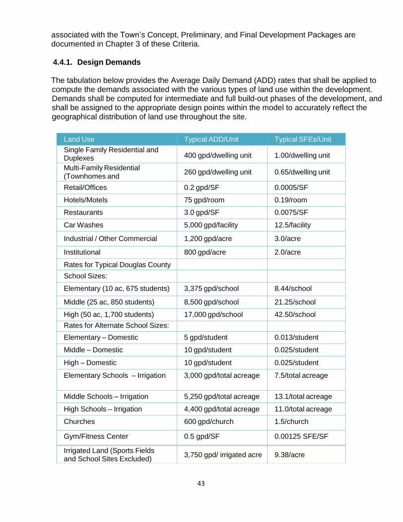
43
associated with the Town’s Concept, Preliminary, and Final Development Packages are documented in Chapter 3 of these Criteria.
4.4.1. Design Demands
The tabulation below provides the Average Daily Demand (ADD) rates that shall be applied to compute the demands associated with the various types of land use within the development. Demands shall be computed for intermediate and full build-out phases of the development, and shall be assigned to the appropriate design points within the model to accurately reflect the geographical distribution of land use throughout the site.
Land Use Typical ADD/Unit Typical SFEs/Unit
Single Family Residential and Duplexes
400 gpd/dwelling unit
1.00/dwelling unit
Multi-Family Residential (Townhomes and Condos)
260 gpd/dwelling unit
0.65/dwelling unit
Retail/Offices 0.2 gpd/SF 0.0005/SF
Hotels/Motels 75 gpd/room 0.19/room
Restaurants 3.0 gpd/SF 0.0075/SF
Car Washes 5,000 gpd/facility 12.5/facility
Industrial / Other Commercial 1,200 gpd/acre 3.0/acre
Institutional 800 gpd/acre 2.0/acre
Rates for Typical Douglas County
School Sizes:
Elementary (10 ac, 675 students) 3,375 gpd/school 8.44/school
Middle (25 ac, 850 students) 8,500 gpd/school 21.25/school
High (50 ac, 1,700 students) 17,000 gpd/school 42.50/school
Rates for Alternate School Sizes:
Elementary – Domestic 5 gpd/student 0.013/student
Middle – Domestic 10 gpd/student 0.025/student
High – Domestic 10 gpd/student 0.025/student
Elementary Schools – Irrigation 3,000 gpd/total acreage 7.5/total acreage
Middle Schools – Irrigation 5,250 gpd/total acreage 13.1/total acreage
High Schools – Irrigation 4,400 gpd/total acreage 11.0/total acreage
Churches 600 gpd/church 1.5/church
Gym/Fitness Center 0.5 gpd/SF 0.00125 SFE/SF
Irrigated Land (Sports Fields and School Sites Excluded)
3,750 gpd/ irrigated acre
9.38/acre
44
4.4.1.1 Water System Average Daily Demands (ADD)
Notes: (1) All tabulated ADD rates include irrigation demands with the exception of multi-family residential, car washes, gyms/fitness centers, and schools. (2) Irrigation demands shall be in accordance with the Irrigation Plan approved by Castle Rock Water and hours of irrigation shall comply with the latest edition of the Town’s Water Use Management Plan. Irrigation demands in this Table are for planning purposes only. Peak irrigation rates for ‘Irrigated Land’ and ‘School Irrigation’ categories tabulated above shall be in accordance with the approved Irrigation Plan, and shall not be based on the peaking factors identified in the section below. (3) The “Irrigated Land” rate identified above may be higher for active sports fields (e.g., irrigated fields within parks) as determined by the approved Irrigation Plan. (4) School sizes in this table are for planning purposes, per the Douglas County School District. Regarding design flows for schools, planned school sizes shall be confirmed with the Douglas County School District and documented in the Utility Report. The tabulated rates shown above shall be applied as appropriate, depending on the information provided by the School District. (5) Reasonable engineering judgment shall be used in determining the estimated ADD for commercial, industrial and institutional sites. Individual evaluation and justification, including fixture unit counts, shall be provided when the proposed use is not specifically represented in the table above, or when the proposed demands will be inconsistent with the tabulated values. For example, each car wash’s unique operating plan, including recycling of wash water, shall be considered. Justification of all non-residential demands shall be addressed in the Utility Report.
4.4.1.2 Demand Factors
Once the ADD has been computed in accordance with the demand rates tabulated above, Maximum Day Demands (MDD) and Peak Hour Demands (PHD) shall be computed by multiplying the ADD by the following factors: Maximum Day Demand/Average Day Demand: 2.5 MDD/ADD Peak Hour Demand/Average Day Demand: 5.5 PHD/ADD
Peaking factors are not applied to irrigation ADD demands. Max Day Demand and Peak Hour Demand are calculated by multiplying the ADD demand by the demand factors. If the site’s irrigation demands are calculated using the table in section 4.4.1, the irrigation ADD is added to the calculated MDD and PHD, computed as follows:
MDD = Domestic ADD X Maximum Day Factor + Irrigation ADD PHD = Domestic ADD X Peak Hour Factor + Irrigation ADD
4.4.1.3 Fire Flows
Fire flows shall conform to the latest edition of the International Fire Code (IFC) and shall be confirmed by the Town’s Fire Department, as described in section 3.6.XII of

45
this criteria. A 50 percent reduction in required fire flow may be allowed for approved residential sprinkler systems, and a 75 percent reduction may be allowed for approved commercial sprinkler systems at the discretion of the Town of Castle Rock Fire Chief. The minimum fire flow for the water distribution system is 1,500 gpm, unless otherwise approved by the Fire Department.
4.4.2 Storage Requirements
The required storage volume associated with a particular development shall be computed as follows:
Storage Volume (MG) = Maximum Day Demand (MG) + Fire Flow (MG)
Example Calculation:
Based on an assumed 1500 gpm two-hour fire and an MDD rate of 75 gpm, the storage requirement would be:
75 gpm x 60 min/hr x 24 hrs = 108,000 gallons
+ 1500 gpm x 60 min/hr x 2 hrs = 180,000 gallons
Total required storage = 288,000 gallons (0.288 MG)
Based on the computed storage volume, Castle Rock Water will evaluate whether the development is compatible with the location and magnitude of the existing and master-planned storage volume within the pressure zone, or if additional storage must be considered to provide the appropriate level of service to the development. Due to hydraulic constraints and limitations within the service area, fire storage within the pressure zone may need to be duplicated as determined by Castle Rock Water.
4.4.3 Minimum Hydraulic Performance Criteria
All mains shall be sized to provide for domestic, irrigation and fire protection demands to all points in the development without violating the pressure, velocity, and headloss criteria set forth herein. The proposed network shall be evaluated by the engineer under the hydraulic conditions stipulated in the following table using an approved hydraulic network analysis model. In some cases, the Town may require the oversizing of certain mains based on required master-planned sizes associated with the overall Town system. Recovery costs of such oversizing shall be in accordance with the Town Municipal Code, and pursuant to applicable executed agreements.

46
Hydraulic Condition Pressure (psi)
Minimum static pressure with zero demand (20% tank stage)
43
Maximum static pressure with zero demand (100% tank stage)
125
Minimum dynamic pressures (based on 20% tank stage):
Max Daily Demand + fire flow (see note below)
20
Peak Hour Demand (see note below)
35
Note: Pressure and Velocity criteria listed above for the MDD plus fire flow and PHD conditions shall be satisfied with one critical distribution loop out of service.
4.4.3.1 Operating Pressures and Pressure Zone Characteristics
The required operating pressures listed above apply to pressures within the mains, and shall be satisfied in accordance with the general pressure zone elevation data tabulated below (Vertical Datum NAVD 88).
Pressure Zone Designation
Max HGL Elev.
Top Elev. Served
Low Elev. Served
1 (Orange) 6192 6072 5915
2 (Yellow) 6352 6230 6065
3a (Blue-east) 6508 6389 6221
3b (Blue-west) 6523 6399 6236
4 (Purple) 6594 6474 6308
5 (Red) 6680 6557 6393
6 (Green) 6824 6700 6537
Notes: (1) Elevations shown above are general guidelines. Engineer shall contact Castle Rock Water to confirm the appropriate numbers for a specific site. (2) Pressure evaluations in areas served solely by PRVs shall be based on the PRV settings, as provided by Castle Rock Water. 4.4.3.2 Assumed Pressures at Existing System Connections
Primary distribution and transmission mains between the supplying storage tank and

47
the development may be required at the discretion of Castle Rock Water to account for the headloss between the supply source and the location of the development under MDD and PHD conditions. In lieu of this information, Castle Rock Water may provide the engineer with assumed Master Plan pressures or HGL elevations at the proposed connections as the necessary boundary conditions for the required hydraulic models. 4.4.3.3 Maximum Velocities and Headlosses
Maximum velocity with Peak Hour Demands: 10 fps Maximum velocity with Max Day Demands: 5 fps Maximum velocity with Max Day + Fire Flow Demands 15 fps Maximum headloss through 16" (transmission): 2.0 ft/1000 ft Maximum headloss through 20” (transmission): 1.5 ft/1000 ft Maximum headloss 24" and larger (transmission): 1.0 ft/1000 ft
Hazen Williams 'C' factor (PVC & DIP): 120
Distribution Main Sizing Minimum Standard
Minimum pipe size (see note below):
8 inches
Minimum pipe size in an arterial street:
12 inches
Valve Spacing Minimum Standard
Largest spacing on transmission mains:
1200 feet
Largest spacing on distribution mains:
600 feet
Note: ‘C' factor includes allowances for minor losses and pipe aging.
4.4.4 General Water System Layout Criteria
4.4.4.1 Location
All water mains and appurtenances shall be installed in public right-of-way, dedicated utility easements and Town property. Water mains shall not be installed parallel to and directly below, any concrete such as sidewalks, trails, curbs, or gutters, and no water manholes or appurtenances shall be located in multi-use trails and sidewalks. Mains shall be located in accordance with the Standard Details available on the Town’s website, unless otherwise approved by variance from Castle Rock Water. In public streets, water mains shall be located near the center of the north and east lane wherever possible, or seven feet minimum from edge of main to
48
flowline where a tree planting zone is designated behind the curb. Under no circumstances shall the edge of a main be closer than five feet from a gutter pan. Water system layouts in cul-de-sacs shall be in accordance with the Town’s Standard Details.
4.4.4.2 Horizontal Layout
Horizontal separation from potable water mains to storm sewers and sanitary sewers shall be ten feet, edge-to-edge. Horizontal separation from raw (untreated) water lines to storm sewers and sanitary sewers shall be five feet, edge-to-edge. Castle Rock Water must specifically approve any variance from this requirement in the event that it has been determined that it is impossible to maintain the specified horizontal separation distance.
Water mains adjacent to developments shall be designed to extend along the entire frontage of the property to be served, from property line to property line, in order that service will thereupon be available to adjacent developers or builders to subsequently extend from in the future. Any off-site water mains necessary to serve the development property shall be extended at the sole expense and obligation of the developer.
Water main alignments between structures (residences, businesses, etc.) shall only be allowed in designated utility tracts for the purpose of looping a water main at the end of a cul-de-sac, and shall include provisions for a main-break swale as set forth in these Criteria. Under no circumstances shall water mains be installed directly below any concrete such as sidewalks, curbs or gutters, except at 90-degree angles where crossings beneath the concrete features are required. No permanent structures, (e.g., retaining walls, trees, light pedestals, sign foundations, power poles, mailboxes, sheds, buildings, private utilities, etc.), shall be within ten feet of a water main. Horizontal separation from water mains to dry utilities and any dry utility infrastructure shall be ten feet, edge-to-edge.
4.4.4.3 Vertical Layout
The minimum depth of cover for water mains from final grade to the top of the water main shall be five feet. The maximum depth of cover for water mains shall be six feet from the top of the pipe to final grade, unless associated with a water main lowering in accordance with the Town’s Standard Details or as otherwise approved in writing by Castle Rock Water. Under circumstances where a deeper main would eliminate the need for an air valve, mains may be constructed with a cover up to 7.5 feet, and the plans shall note that high points are to be avoided over such a reach.
At all utility crossings, the information in the following list shall be provided on the Construction Drawings. Where water main lowerings are utilized, the Construction Drawings shall additionally identify the coordinates of the beginning and end of the

49
lowering, and the type, size, and degree of all bends that comprise the lowering.
Axial joint deflection information, as approved, including lay length and
deflection angles
Materials and sizes of the crossing utilities
Coordinates of the crossing
TOP and BOP elevations at the crossing
Vertical clear distance between crossing utilities
Coordinates at each end of any concrete encasements or casings
Configuration and thickness of any concrete encasements or casings
4.4.5 Pipe Joint Deflection
Design of DIP deflections shall be in accordance with the latest edition of AWWA C600 entitled “Installation of Ductile Iron Water Main and their Appurtenances.” Design of PVC pipe deflections shall be in accordance with the latest edition of AWWA Manual C605-13 entitled “Underground Installation of Polyvinyl Chloride (PVC) and Molecularly Oriented Polyvinyl Chloride (PVCO) Pressure Pipe and Fittings.”
Water main joint deflection angle for DIP and PVC shall not exceed one half of the manufacturer’s maximum allowable deflection for the specified pipe diameter and lay length, or one half of the maximum deflection allowed by AWWA, whichever is less. Fittings, bends, or couplings that allow additional angular offset shall be used to achieve gradual alignment changes that exceed the axial joint deflection limits stated herein. All pipe segments must be installed without bending pipe lengths. All change in direction must occur through angular joint deflection or fittings.
4.4.6 Distribution Main Looping
All water systems shall be effectively looped. No dead-end lines will be permitted, except lines extending into cul-de-sacs serving no more than twelve single-family residential units or single-family equivalents (SFEs) and with a length of no more than 400 feet. A fire hydrant shall be placed at the deepest point of any cul-de-sac, as shown in the Town’s Standard Details. Dead-ends on lines that will not be extended shall be provided with permanent hydrants at the terminus of the dead-end.
Water quality is a design consideration for any system, and an aging analysis and/or model may be required at the discretion of Castle Rock Water to ensure that water quality concerns will not be created as a result of any proposed distribution system layout. In accordance with the Town’s Standard Details, water quality sampling stations may be required by Castle Rock Water at specific locations within new developments to continue to adequately monitor the overall quality of the Town’s expanding system.

50
4.4.7 Transmission Mains
All water mains 16 inches and larger in diameter shall be classified as "transmission mains," and shall correspond to the sizes established in the latest edition of the Town’s Water Master Plan. Raw water lines that run between wells and points of disinfection or purification, regardless of size, shall also be considered transmission mains. In accordance with the Town’s Standard Details, air and vacuum release valves shall be installed along transmission mains at all high points and pumping manholes shall be installed at all low points. Temporary blow-off assemblies shall be installed in accordance with the Town’s Standard Details at all temporary dead-ends along transmission mains. No service connections, including irrigation taps, shall be permitted on a transmission main.
Transmission main valves shall be butterfly valves, and shall be required on every branch where two transmission mains connect. Valves shall be installed in accordance with the Town’s Standard Details and shall be located ten feet from the connection wherever possible, but shall in no case be less than five feet. Maximum valve spacing along transmission mains shall be no more than 1,200 feet, provided there are no intersecting distribution mains. Where distribution mains connect to transmission mains, a gate valve is required on the distribution main, and the goal shall be to locate butterfly valves along the transmission main so that no more than 18 residential units and one fire hydrant will be out of service at any given time, whether for maintenance or in the event of a water main break. Every effort shall be made to achieve this goal. It is the responsibility of the engineer to verify compliance with this requirement by considering effective looping, as well as other applicable requirements. Additional valves shall be considered by the engineer to minimize inconveniences and safety hazards during repairs at critical locations within the system, and to provide for the ability to conduct water quality monitoring and alleviate water quality concerns that may be reasonably anticipated. In the case of water mains larger than 24 inches, the engineer shall submit pipeline materials and valves specifications to the Town for review and approval prior to the Town's approval of the Construction Drawings.
4.4.8 Utility Crossings
Construction Drawings shall show details of the crossings of potable water mains and all other utility lines (sanitary sewer mains and force mains, reuse, raw, and storm sewer). Utility lines shall be protected from one another at crossings as detailed in the subsections that follow in order to protect the potable water supply to the greatest extent possible. In general, water mains crossing sanitary sewers, force mains, or storm sewers shall be laid to provide a minimum vertical clearance of 18 inches between the outside of the water main and the outside of the sanitary sewer, force main or storm sewer. In all cases, proper soil compaction, suitable backfill or other structural support shall be provided to preclude settling and failure of either pipe at the crossing. Special structural support for the crossing pipes may be required at the

51
discretion of Castle Rock Water. Unless otherwise approved by variance, the criteria set forth below shall apply to both the crossing of new mains, and the crossing of a new main and an existing main.
4.4.8.1 Water Main Crossing Over a Sanitary Sewer Main
When a water main crosses over a sanitary sewer main or force main, regardless of vertical clearance, one full standard length section of water pipe shall be located such that both joints will be as far from the sanitary sewer or force main as possible. When a water main crosses over a sanitary sewer main or force main with less than two feet between the outside of the water main and the outside of the sanitary sewer or force main, the sanitary sewer or force main shall be encased with a minimum of six inches of concrete from springline to six inches above the top of the sanitary sewer main or force main. The encasement shall extend along the centerline of the sanitary sewer main or force main for a minimum of one foot beyond the outside of the water main at each end. When less than 18 inches of vertical clearance exists between the top of the sanitary sewer or force main and the bottom of the water main, the water main shall be lowered or deflected under the sanitary sewer or force main wherever possible to achieve a minimum vertical clearance of 18 inches and the requirements of Subsection 4.4.9.2 shall apply. These situations will be reviewed by Castle Rock Water on a case-by-case basis.
4.4.8.2 Water Main Crossing Under a Sanitary Sewer Main
When a water main crosses under a sanitary sewer main or force main, regardless of vertical clearance, one full standard length section of water pipe shall be located such that both joints will be as far from the sanitary sewer or force main as possible. In all cases, a minimum of 18 inches of vertical clearance shall be provided at the crossing, which may require that the water main be lowered in conformance with the Town’s Standard Details.
4.4.8.3 Water Main Crossing Over a Storm Sewer
When a water main crosses over a storm sewer, regardless of vertical clearance, one full standard length section of water pipe shall be located such that both joints will be as far from the storm sewer as possible. When a water main crosses over a storm sewer with less than two feet between the outside of the water main and the outside of the storm sewer, the storm sewer shall be encased with a minimum of six inches of concrete from springline to six inches above the top of the storm sewer. The encasement shall extend along the centerline of the storm sewer for a minimum of one foot beyond the outside of the water main at each end. When less than 18 inches of vertical clearance exists between the top of the storm sewer and bottom of the water main, the water main shall be lowered or deflected under the storm sewer wherever possible to achieve a minimum vertical clearance of 18 inches, and the requirements of Subsection 4.4.9.4 shall apply. In all cases, the engineer shall evaluate the potential for water main freezing, and if appropriate, the design shall incorporate preventative measures that shall be reviewed and approved by Castle Rock Water.

52
4.4.8.4 Water Main Crossing Under a Storm Sewer
When a water main crosses under a storm sewer, regardless of vertical clearance, one full standard length section of water pipe shall be located such that both joints will be as far from the storm sewer as possible. In all cases, a minimum of 18 inches of vertical clearance shall be provided at the crossing, which may require that the water main be lowered in conformance with the Town’s Standard Details. In all cases, the engineer shall evaluate the potential for water main freezing, and if appropriate, the design shall incorporate preventative measures that shall be reviewed and approved by Castle Rock Water. When water mains cross a storm sewer, regardless of vertical clearance and which pipe crosses over the other, each joint of the storm sewer within the trench width of the crossing shall be encased in a concrete collar at least six inches thick and extending at least six inches each side of each joint. When water mains cross under a storm sewer pipe greater than 48 inches in diameter, or a culvert 4’ x 4’ or larger, the water main must be installed within a casing pipe that conforms with section 4.4.6 of this criteria, and extends at least five feet beyond the outside edge of the culvert, or as determined by plan review. 4.4.8.5 Limits on Minimum Vertical Clearance
Under no circumstances shall the minimum vertical clearance between any two crossing utilities be less than 18 inches, unless approved by variance in accordance with Section 1.9 of these Criteria.
4.4.9 Bored Crossings
When a water main passes under a State roadway, an arterial or collector roadway as defined by the Town, railroad, navigable waterway, drainageway or irrigation ditch, the main shall be located within a steel casing pipe, and boring under the obstacle is required unless otherwise allowed to be open cut by the jurisdictional entity being crossed. The carrier pipe shall be sleeved and sealed within the casing pipe in accordance with the Town’s Standard Details, and shall have a minimum of five feet of cover to the top of casing. The casing pipe shall extend the entire width of the right-of-way or easement of the crossing structure, the entire width of the one hundred year floodplain, or as directed by the Town or other jurisdictional entity. Valves with appropriate restrained lengths, per the Town’s Standard Details, shall be located near each right-of-way or easement line, just beyond the ends of the casing pipe, to provide for the isolation of the main during maintenance or inspection.
In the event that the roadway, railroad, navigable waterway, drainageway, irrigation ditch or other such crossing is widened, the casing pipe shall be extended to the newly defined full width of the right-of-way, easement or crossing structure, or otherwise the water main and casing pipe shall be realigned and rebored to span the full width of the newly widened crossing. Valves shall be relocated as necessary to just beyond the ends of the newly extended casing pipe, near each right-of-way or easement.
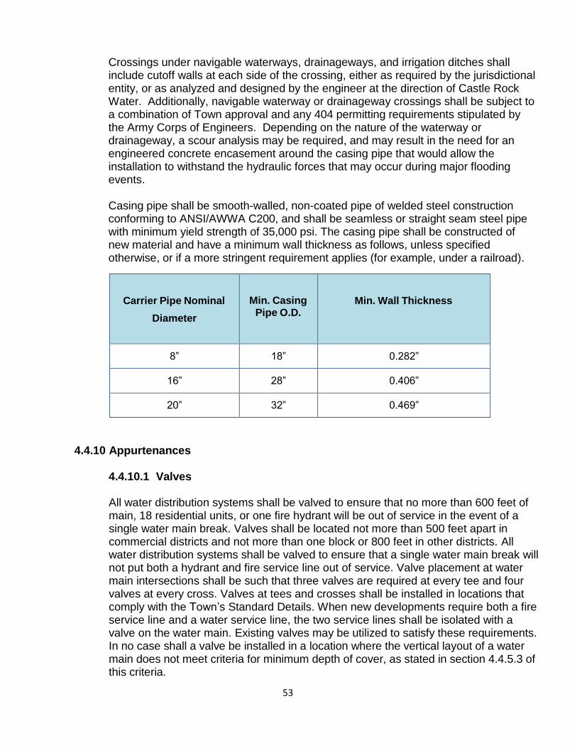
53
Crossings under navigable waterways, drainageways, and irrigation ditches shall include cutoff walls at each side of the crossing, either as required by the jurisdictional entity, or as analyzed and designed by the engineer at the direction of Castle Rock Water. Additionally, navigable waterway or drainageway crossings shall be subject to a combination of Town approval and any 404 permitting requirements stipulated by the Army Corps of Engineers. Depending on the nature of the waterway or drainageway, a scour analysis may be required, and may result in the need for an engineered concrete encasement around the casing pipe that would allow the installation to withstand the hydraulic forces that may occur during major flooding events.
Casing pipe shall be smooth-walled, non-coated pipe of welded steel construction conforming to ANSI/AWWA C200, and shall be seamless or straight seam steel pipe with minimum yield strength of 35,000 psi. The casing pipe shall be constructed of new material and have a minimum wall thickness as follows, unless specified otherwise, or if a more stringent requirement applies (for example, under a railroad).
Carrier Pipe Nominal
Diameter
Min. Casing Pipe O.D.
Min. Wall Thickness
8”
18”
0.282”
16”
28”
0.406”
20”
32”
0.469”
4.4.10 Appurtenances
4.4.10.1 Valves
All water distribution systems shall be valved to ensure that no more than 600 feet of main, 18 residential units, or one fire hydrant will be out of service in the event of a single water main break. Valves shall be located not more than 500 feet apart in commercial districts and not more than one block or 800 feet in other districts. All water distribution systems shall be valved to ensure that a single water main break will not put both a hydrant and fire service line out of service. Valve placement at water main intersections shall be such that three valves are required at every tee and four valves at every cross. Valves at tees and crosses shall be installed in locations that comply with the Town’s Standard Details. When new developments require both a fire service line and a water service line, the two service lines shall be isolated with a valve on the water main. Existing valves may be utilized to satisfy these requirements. In no case shall a valve be installed in a location where the vertical layout of a water main does not meet criteria for minimum depth of cover, as stated in section 4.4.5.3 of this criteria.

54
Valves shall be located to provide for the extension, pressure testing, and chlorination of new water mains without the disruption of the existing system. Additional valves shall be considered by the engineer to minimize inconveniences and safety hazards during repairs at critical locations within the system, and to provide for the ability to conduct water quality monitoring and alleviate water quality concerns that may be reasonably anticipated.
Valves larger than twelve inches shall be butterfly valves, with valve operators located on the north and east sides of the mains. Main line valves shall generally be located at a point on the main that is intersected by an extension of the right-of-way line in accordance with the Town’s Standard Details. Where valve location on right-of-way lines is not reasonable, valves shall be located ten feet from the connecting tee, cross, or elbow wherever possible, but in no case shall the distance be less than five feet. Under no circumstances shall a valve be located in concrete, such as sidewalks, crosspans, aprons, curbs, or gutters.
Valve boxes shall be in accordance with Town Standard Details and shall be brought up to grade at the time of pavement placement or overlay. Drop-in style valve box adjusting rings shall not be allowed. Any valve located in an unpaved area shall have a reinforced concrete collar around the valve box and the accompanying marker post in accordance with the Town’s Standard Details. Temporary dead-ends on any water main shall include a temporary blow-off assembly, per the Town’s Standard Details. Dead-ends on lines that will not be extended shall be provided with permanent hydrants at the terminus of the dead-end.
4.4.10.2 Pressure Reducing Valves
Pressure-reducing valve (PRV) installations are used to control and maintain pressure between distribution zones, and shall be installed at locations determined by Castle Rock Water in accordance with the Water Master Plan. Downsizing of the main shall not be allowed at the valve. Castle Rock Water shall determine the PRV pressure settings necessary to maintain the Town’s master-planned pressure zones, shall be present when PRVs are put into service, and shall inspect these facilities.
The need for PRVs other than those specified in the Water Master Plan shall be determined by Castle Rock Water, and shall be based on the existing zones boundaries and the proximity of the existing distribution system to the development. It is the Town’s intent that the number of pressure reducing stations be minimized to the greatest extent possible in favor of internal looping within the pressure zone. Consequently, the justification for any new PRV shall be submitted to Castle Rock Water by the engineer for review and approval. If approved, the design of the facility shall be in accordance with the Town’s Standard Details and may require SCADA automation at the discretion of Castle Rock Water. PRV access hatches should be located outside of roadways if at all possible.
4.4.10.3 Fire Hydrants
Fire hydrant spacing and proximity to structures shall be as required by the latest
55
version of the International Fire Code (IFC). All hydrants shall be installed to conform to the grade and alignment shown on the plans.
Hydrants shall have the "steamer connection" located no closer than 18" to finished grade. The steamer connection shall face the direction as shown on the approved plans or as required by the Fire Department. No vertical extensions are allowed on new construction, and the hydrant shall be installed such that the bury line of the hydrant is at final grade. Each section of water main with a hydrant shall be valved in such a way that the hydrant may be isolated for maintenance or repairs, and all hydrant laterals shall contain a shutoff valve in accordance with the Town’s Standard Details. All hydrant laterals shall be fully restrained using Meg-a-Lug joint restraint or approved equal.
All fire hydrant locations will ultimately be subject to the approval of the Town Fire Chief. Hydrants shall be placed as shown in the Town’s Standard Details within the right-of-way or in a utility easement, in accordance with Section 4.5. Wherever possible, hydrants shall be located on the same side of the street as the water main, unless otherwise directed by Castle Rock Water. Preference shall be given to locating hydrants near street corners, rather than to locations near streetlights. Hydrants shall be located at the entrance of every street and at the end of every cul-de-sac, in accordance with the Town’s Standard Details.
When hydrants are to be installed at locations other than street intersections, they shall be located at the extension of property side lot lines. In no case shall a hydrant be located closer than five feet to obstructions, driveways, etc., and no closer to ten feet from a curb inlet. Fences, landscaping, etc., shall in no way hinder the operation of the fire hydrant.
Fire hydrant lateral lines shall be set at 90 degrees to mains, contain no vertical or horizontal bends, and shall be no more than 70 feet in length between the hydrant and the main. Under no circumstances shall any tap be made on a hydrant lateral.
4.4.10.4 Thrust Restraint
All bends, tees, plugs, dead-ends, wet taps (in certain cases), hydrants, and blow-offs shall be designed and constructed with concrete thrust blocks in accordance with the Town’s Standard Details. If the soil-bearing capacity is unknown, it shall be assumed to be 2,000 pounds/ square foot in determining the appropriate size of the thrust block. In addition to thrust blocks, joints shall be mechanically restrained for the required distances from valves and fittings in accordance with the Town’s Standard Details, and shall incorporate restraint devices as identified on the Town’s Approved Materials List. The entire length of fire hydrant lines and fire service lines shall be restrained.
4.4.10.5 Meters
All service connections, with the exception of fire service laterals, shall be metered. In general, residential and commercial meters shall be installed inside the buildings

56
unless otherwise approved by Castle Rock Water. All meter pit installations shall conform to the Town’s Standard Details, and the make and model of the meter shall be as determined by Castle Rock Water.
All meters connected to the Town's water distribution system shall be the property of the Town. Under no circumstances shall anyone other Castle Rock Water personnel remove a water meter once the pit, vault, or authorized inside installation has been inspected and approved. No connections shall be made in the meter pit other than those directly related to the meter and bypass. Single-family residential irrigation system connections shall be made downstream from the meter and backflow prevention assembly. All other uses require irrigation service connections separate from the domestic service connection unless otherwise approved by Castle Rock Water. For all water meter installations, detailed drawings of the proposed installation and water fixture unit counts shall be included as an integral part of the building plans submitted to Castle Rock Water for review. There shall be no electrical wiring allowed in any water meter pit or vault unless authorized in writing by Castle Rock Water. Fixture unit counts for residential, commercial or industrial use shall be determined by a Registered Professional Engineer in the State of Colorado in accordance with the procedures set forth in the IPC and IRC, and as approved by Castle Rock Water.
4.4.10.6 Fire Protection Service Lines
Fire service lines shall be Ductile Iron (3-inch and larger) or Type K copper (2-inch and smaller) from the main to the backflow prevention assembly, unless approved by the Town of Castle Rock Fire and Rescue Department. All fire service lines shall be fully restrained in their entirety.
Valves on newly-constructed fire service lines shall be located on the service lateral behind the curb, gutter or sidewalk, and within two to five feet inside the right-of- way line, wherever possible. The customer/owner shall own and maintain all private fire service lines from the tap on the main to the building. All fire sprinkler taps shall be installed with a backflow prevention assembly approved by Castle Rock Water and as required by the latest edition of the Colorado Cross-Connection Control Manual. A flow switch shall be provided on the riser that indicates whether or not water has flowed through the line. Tapping these lines for fire hydrants, domestic water, and/or any other purpose shall not be permitted. Commercial properties requiring a domestic service line and a fire protection service line shall have separate taps for each in accordance with the Town’s Standard Details. Residential properties requiring a domestic service line and a fire protection service line shall be served by a single tap, with ownership and responsibility as set forth in Section 4.4.15.1 Ownership.
Fire protection service lines and Fire Department Connection (FDC) locations shall be included on the Construction Drawings. FDCs are to be freestanding in a location approved by the Fire Code Official. The connection shall be at a distance of one and a half times the building height, offset from one of the corners of the building for easy accessibility. The line to the FDC shall terminate with a five-inch Storz fitting with
57
permanently attached cap, and a 22-30 degree elbow to direct the Storz halfway between horizontal and the ground. The Fire Code Official may waive the requirement of a free standing FDC due to distance from the building. Refer to the Town of Castle Rock Fire and Rescue Department’s “Fire Department Connection (FCD) Detail Requirements” for further information.
4.4.10.7 Manholes
Manholes shall be installed in conjunction with all air release vaults in accordance with the Town’s Standard Details. Manhole lids shall not be aligned with vehicle wheel paths, or within two feet either direction of the street crown.
4.4.10.8 Backflow Prevention Assemblies
To prevent backflow contamination of the Town's potable water mains, a backflow prevention assembly shall be installed where pressures downstream of the water meter could exceed those in the main, and where any unsafe water or contaminated materials could be discharged or drawn into the potable water system under a condition of back-siphon age. The assembly shall be placed downstream of the water meter and shall be installed and tested in accordance with Town Municipal Code Section 13.06. The assemblies shall meet the most restrictive requirements set forth in the latest editions of the Town of Castle Rock and State of Colorado Cross-Connection Control Manuals, and shall further meet the requirements of the IPC, IFC and IRC, as applicable. Backflow prevention assemblies shall be installed and located to provide for proper operation of the device, and easy access for annual testing and maintenance.
Determination of the particular device shall be at the discretion of Castle Rock Water. All service connections, including irrigation and fire line connections, shall require backflow prevention. 4.4.10.9 Booster Pumps
A. Distribution Booster Pumps. Distribution booster pumps must be located or
controlled so that:
They will not produce negative pressure in their suction lines.
Pumps installed in the distribution system must maintain inlet pressure, as required in Section 8.2.1 under all operating conditions (exclusive of pumps connected to transmission piping).
Systems designed to operate in an automatic mode have automatic shutoff or a low pressure controller to maintain at least 20 psi (140kPa) in the suction line under all operating conditions, unless otherwise acceptable to the Department. Pumps taking suction from ground storage tanks and designed to operate in an automatic mode must be equipped with automatic shutoffs or low pressure controllers, as recommended by the pump manufacturer.
Automatic control devices must have a range between the start and cutoff pressure, which will prevent excessive cycling.

58
B. Individual Residential Booster Pumps
Private booster pumps for any individual residential service from the public water supply main must only be permitted as allowed by local agencies having jurisdiction. Where allowed, private booster pumps must meet the requirements above.
4.4.10.10 Combination Air Release and Vacuum Valves
Combination air relief valves and vaults shall be located at all high points in the transmission and distribution system in accordance with the Town’s Standard Details.
4.4.10.11 Blow-off Pumping Manholes
In accordance with the Town’s Standard Details, a pumping manhole (low point blowoff) may be required at all low points on transmission mains.
4.4.10.12 Tracer Wire and Warning Tape
Tracer wire shall be affixed to the top of all water mains regardless of pipe material and terminated in test stations located behind each fire hydrant or in valve boxes in accordance with the Town’s Standard Details and Water Utility Construction Notes. The maximum distance between test stations or tracer wire boxes shall be 500 feet. Warning tape shall be installed one foot above the top of pipe on all water mains, regardless of pipe material.
4.4.11 Fill Areas
Where water mains will be constructed in fill areas, all fill materials shall be placed and compacted to final grade and specification prior to the installation of the water main and appurtenances. All fill material shall meet the Town’s standards and be approved by Castle Rock Water. Water mains within fill areas shall have restrained joints if directed by Castle Rock Water in accordance with these Criteria.
4.4.12 Trail Access
Where water mains cannot be located in public right-of-way, the facilities shall be located in areas that allow direct access by maintenance vehicles. Proposed trails to be used to access water mains and appurtenances must meet the following requirements, and shall be submitted for review and approval by Castle Rock Water:
1. In accordance with Section 4.5, the longitudinal slope must not exceed ten
percent and the cross slope must not exceed four percent, unless approved by variance.
2. The Parks and Recreation Department must approve this use. 3. The width of the drivable surface shall be a minimum of ten feet for a straight
portion of trail and at least twelve feet wide for curved portions, depending on the curve radii. A shoulder may be required.

59
4. The trail shall be designed to support a minimum vehicle weight of 60,000 pounds.
5. The trail must be in a Utility, Public Access and Trail Easement a minimum of 25 feet wide in accordance with Town Regulations.
Information regarding the width, type and depth of material specified for trails to be used to access water system facilities shall be submitted for review by Castle Rock Water, and shall include acknowledgement from the Parks and Recreation Department that utility access is approved for the particular trail.
4.4.13 Main-Break Swale Design
All water mains to be constructed between structures (residences, businesses, etc.) must have a “main-break” swale or channel that provides adequate capacity in the event of a water main break. The swale must be located in a dedicated open space or utility tract maintained by the Owner and shall be designed as follows:
1. Flow Calculation: Use 16 fps for the diameter of the pipe in question and
calculate the swale design capacity as eighty percent of the pipe flow. 2. The Final Utility Report must contain the calculation of the required evacuation
flow and calculations for the proposed swale design showing that the capacity is sufficient for this flow.
3. The Final Utility Report and CD grading plans shall contain a cross-section of the proposed swale including the depth of water. The swale side slopes shall not exceed 4:1.
4. The proposed swale shall have a minimum bottom width of twelve feet to accommodate maintenance activities.
4.4.14 Future Connections
A temporary blow-off assembly, in accordance with the Town’s Standard Details, is required at the terminal end of any water main that is to be extended in the future. Such discontinued mains shall be valved such that only a single valve will need to be closed when the main is extended. Joints shall be restrained an adequate distance from the valve per the Town’s Standard Details to ensure that the valve will not blow off when the line is exposed for extension. No service taps shall be allowed between the isolation valve and the dead end on any main that may be extended in the future.
4.4.15 Water Service Lines
All single family residential dwellings (attached and detached, and each unit of duplexes), shall be served by a separate, independent water service line and meter. Multi-family dwelling units mean a building or portion thereof, designed for or occupied by three (3) or more families living independently of each other, which may include condominiums or townhouse units. Apartment buildings are always considered multifamily dwelling units and shall be served by a master meter to each building. Multifamily complexes that are multi-level buildings where multi-family dwelling units

60
share common floors/ceilings may be served by a master meter and dedicated service line to each building. This may include condominiums and apartments. System development fees imposed on this style of condominium project (not apartment project) shall be calculated in accordance with 13.12.0180 A and C of the municipal code, based on the size of the master meter, but shall not exceed the aggregate system development fees obtained by imputing a separate meter for each individual residential dwelling unit. Townhouse-style apartments that share common walls may be served by a master meter and dedicated service line, as long as the meter is in a dedicated mechanical room or meter pit accessed in a common area without entering private living or garage space. Individually owned condominiums and townhomes (that only share common walls) shall have a dedicated service line and meter to each dwelling unit. System development fees imposed on this style of condominium and townhome project shall be calculated in accordance with 13.12.0180 A and C of the Municipal Code, based on the size of the master meter, but shall not exceed the aggregate system development fees obtained by imputing a separate meter for each individual residential dwelling unit. Each individual building in multi-family dwelling complexes, as defined above, and each commercial business, industrial, and irrigation customer shall be served by a separate, independent water service line and meter.
4.4.15.1 Ownership
All water service lines are private improvements. All water service lines, valves, and appurtenant fixtures, with the exception of the water meter set, are owned and must be maintained by the property owner until the property has passed the meter set inspection. Until that time, all costs for installation, maintenance, and/or replacement of these are the responsibility of the property owner. Once the property has passed the meter set inspection, Castle Rock Water will take over ownership and repair service leaks between the corporation stop and the inlet to the curb stop only. The owner is responsible for all other service line repairs or replacement from the curb stop to the building.
4.4.15.2 Layout
The developer shall install a service line stub-out from the water main to each individual lot, including the curb stop box and meter pit. Where sidewalks are proposed, the stub-out shall be constructed to five feet beyond the back of the sidewalk. Where sidewalks will not be constructed, the stub-out shall be constructed a minimum of one foot beyond the property line. The stub-outs shall be plugged and the end marked with a blue painted T-post installed in the ground directly above the location of the plugged end. Where curbs exist, the location of each service line shall be marked on the curb with a “W” impression in the concrete.
All service line sizes and locations shall be shown on the water system
61
Construction Drawings to be approved by Castle Rock Water. The services shall be constructed as shown on the CDs unless otherwise approved in writing by Castle Rock Water. The stationing, length, size and direction of the service line shall be shown in plan view on the CDs. The invert elevation, and finished ground elevation at the end of the service shall be shown on the profile.
Additional service line layout details are as follows, which shall be in accordance with the Town’s Standard Details: 1. Service taps 2-inch and smaller shall use a tapping sleeve that conforms to
the town’s standard details. All service connections larger than 2-inch, regardless of material, shall be made using a cut in tee.
2. All service lines 3/4-inch through 2-inch shall be Type K copper or approved equal and shall be installed continuous without joints between the corporation stop at the water main and the meter curb stop.
3. For new services larger than 2-inch, service line size shall be 3-inch, 4- inch, 6-inch, or 8-inch, and the connections shall be made with mechanical joint swivel tees installed at the time of mainline construction.
4. There shall be no “size-by-size” (e.g., 8” x 8”) taps made to new or existing mains.
5. Service lines shall be laid with a minimum of ten feet of clear separation, measured edge-to-edge, from any sanitary or storm sewer main or manhole, sanitary service line, or force main.
6. A minimum of 18 inches of vertical clearance shall be provided at all crossings with sanitary sewer mains and services, force mains, and storm sewers.
7. Services shall have a minimum of five feet of cover and shall not be located under driveways.
8. Service lines shall be constructed perpendicular to the front property line. 9. The service line shall be a minimum of five feet from the side property line
and shall not be constructed through or in front of any adjoining property. 10. Service lines may be bored under any existing sidewalks or curbs in lieu
of trenching and concrete replacement. Any required street cut permits must be coordinated with, and obtained from Public Works.
11. Service lines crossing over storm sewers have a high potential for freezing. In any location where a water service line crosses over a 24” or larger storm sewer, and/or does not have a minimum depth of four feet, the water service line shall be insulated.
4.5 Easements
Where mains cannot be installed in the right-of-way, they shall be located within utility easements approved by the Town and shall be centered in the easement. The minimum easement width shall be twenty feet for one utility, thirty feet for two utilities, and forty feet in width for three utilities. Site-specific circumstances may dictate the need for wider easements. Utility easements and dedicated utility tracts shall be defined by bearings and distances around the perimeter of the easement. Centerline legal descriptions are not acceptable.
62
The main shall be located a minimum of ten feet from and parallel to the edge of the utility easement. All meters and fire hydrants not installed within the right-of-way will require an easement dedication ten feet wide and extending three feet behind the meter or hydrant. If the meter or hydrant easement is longer than ten feet, the width of the easement shall be a minimum of twenty feet. Fire hydrants and meters shall be centered in all such easements.
All utility easements shall be for the exclusive use of the Town. No permanent structures, (e.g., retaining walls, trees, light pedestals, sign foundations, power poles, mailboxes, sheds, buildings, service lines running parallel, etc.), shall be placed in the easement. Any temporary structures placed in the easement, including paving and fencing, shall be removed and replaced by the owner upon the request of Castle Rock Water so that maintenance may be performed. The owner of the land shall agree to hold the Town harmless for any loss of property or landscaping and irrigation removed from the easement or damaged due to maintenance activities, and all associated costs. All utility easements shall meet the following minimum criteria to provide vehicular access for Castle Rock Water:
1. Maximum cross slope of four percent and a maximum longitudinal slope of ten percent. 2. No trees, large boulders or permanent structures as defined above shall be placed within
the easements. 3. Easements may not straddle residential property lines, but shall be placed adjacent or
coincident with the property line, lying wholly within one property or the other. In limited cases, easements may straddle commercial property lines and will be reviewed by Castle Rock Water on a case-by-case basis.
Where it is necessary to locate a water main along back lot lines, the main shall be offset a minimum of ten feet from the lot line, and the alignment shall be specifically approved by Castle Rock Water to provide reasonable access for maintenance crews.
4.6 Utility Easement Note Required on Plats
The following dry utility easement note shall be required on Preliminary Plats, Final PD Site Plans, and Final Plats approved by the Town.
“Unless otherwise noted, all lots shall have a ten-foot utility easement along the front and rear lot lines and along all public rights-of-way and shall have five-foot utility easements along each side lot line. These utility easements are for the installation, maintenance and operation of utilities and drainage facilities including, but not limited to, water meters, fire hydrants, curb boxes, electric lines, gas lines, cable television lines, fiber optic lines, and telephone lines, as well as perpetual right for ingress and egress for installation, maintenance and replacement of such lines. Dry utility crossings may be permitted in other utility or drainage easements provided that any necessary crossing of the Town’s Utility is at a ninety-degree angle. In all cases, prior approval from Castle Rock Water shall be obtained for dry utility crossings of exclusive wet utility easements and exclusive drainage easements.”
63
Chapter 5 – Pump Station Design Criteria
5.1 General
5.1.1 Scope
If permitted, the developer shall submit a complete set of design calculations and drawings to Castle Rock Water for review and approval in accordance with the Criteria set forth herein. Design, material, equipment and construction of the facilities shall conform to all applicable local, State and Federal regulations, codes and standards.
5.1.2 Castle Rock Water Review and Approval
New potable water pump stations must be specifically approved by Castle Rock Water. If approved, the developer shall submit a utility report with a complete set of design calculations and drawings for review and acceptance by Castle Rock Water.
5.1.3 Relationship to Other Standards
New potable water pump stations shall conform, at a minimum, to the latest edition of the Colorado Department of Public Health and Environment (CDPHE) Design Criteria for Potable Water Systems. Castle Rock Water will require that the developer’s engineer prepare the “Application for Construction Approval” for submittal to the CDPHE, Tri-County Health Department (TCHD), and DRCOG as required by these agencies.
5.1.4 Reference Design Documents
Primary standards and reference publications pertinent to the design of potable water pump stations within the Town of Castle Rock are listed below. Unless otherwise specified, the latest editions shall apply. Also refer to the Reference Design Documents in Section 4.1 of these Criteria.
Colorado Department of Public Health and Environment (CDPHE) Design
Criteria for Potable Water Systems
Recommended Standards for Water Works, as published by the Water Supply Committee of the Great Lakes-Upper Mississippi River Board of State and Provincial Public Health and Environmental Managers
5.1.5 Location
The pump station shall be so located that the proposed site will meet the requirements for sanitary protection of water quality, hydraulics of the system, and protection against the interruption of service by fire, flood, or any other hazard.

64
5.1.6 Flood Protection
Electrical and mechanical equipment associated with pump stations shall be located one foot above the 100-year floodplain elevation or highest recorded flood elevation, whichever is highest, and shall remain fully operational and accessible during such an event. Local, State and Federal regulations pertaining to floodplain obstructions shall be satisfactorily accounted for in the design. Grading shall be provided to protect the site by directing surface flows away from the facilities.
5.1.7 Accessibility and Security
The facilities shall be safely accessible by maintenance vehicles during all weather conditions. The facility should be located off the traffic way of streets and alleys and secured against unauthorized entry. Depending on the nature and location of the facility, security fencing with controlled entry keypads, card-reader access to buildings, security cameras, lockable access hatches, and motion-detection safety lighting may be required by Castle Rock Water.
5.2 Minimum General Pump Station Design Criteria
The following list of general provisions and prohibitions shall apply to the design of potable water pump stations:
1. Inaccessible installations shall be prohibited. 2. Screened ventilation shall be provided to prevent the entry of small animals and
insects. Ventilation systems shall be disposable filters to prevent the entry of windborne dust.
3. Adequate heating and cooling shall be provided to insure safe and efficient operation of all piping, pumping and electrical equipment, instrumentation, and alarms.
4. Flow rate, suction and discharge pressures, and pump motor status instrumentation shall be provided for all discharge lines.
5. Instrumentation and telemetry shall be as specified in the Supervisory Control and Data Acquisition System (SCADA) section of these Criteria. Castle Rock Water staff shall be involved in establishing the operational control logic for the pump station, and shall be contacted in a timely manner so as to have ample opportunity to provide input during the design phase.
6. Corrosion protection shall be implemented to protect underground steel and iron. 7. Frost-proof gravity drain lines or sump pumps shall be provided for pump station
drainage. 8. Water shall be prevented from backing up into the pump station from other sources
(e.g., check valve on drain line). 9. Where economically feasible, standardized pumping equipment shall be used to
facilitate interchangeability with equipment utilized elsewhere by Castle Rock Water.
10. Special care shall be exercised in the selection of pumping units and associated components to prevent pressure surges and ensure the suitability, flexibility, and adaptability of the units to the hydraulic conditions of the system.
11. Horsepower rating of each pump motor shall be such that the motor will continuously

65
carry the maximum load possible at any point on the pump curve without exceeding the motor nameplate rating, and without using the service factor. The motors shall conform to the requirements of Section 5.5 below.
12. Pumps shall meet the net positive suction head requirements as published by the manufacturer.
13. Electrical design, equipment selection, and installation practices are subject to prior review and approval by Castle Rock Water. Sufficient electrical outlets and wall lighting shall be provided in the pump room.
14. The pump room shall be separated from the electrical/control room by a wall/door to prevent water damage in the event of a pipe break.
15. Slow-closing regulation valves and check valves, and other surge relief components, shall be evaluated for use in the system to minimize and control water hammer.
16. Ample clearances between equipment shall be provided for operation and maintenance activities.
17. Certified manufacturer’s pump performance curves shall be submitted to Castle Rock Water for review and approval.
5.3 Pump Station Conditional Design Criteria
Depending on the function and location of the pump station, any or all of the following provisions may be required by Castle Rock Water:
1. Aesthetically pleasing building architecture compatible with the surrounding area and
other Town facilities 2. Attractive, water conserving landscaping around the pump station, in accordance with
the Town’s Landscape Regulations, and exterior and interior lighting. The use of skylights and windows to maximize the natural lighting inside the buildings is encouraged.
3. Access and parking for vehicles on the pump station site 4. Additional space for future expansion of pump(s), including VFDs, and piping 5. Bridge crane or access for a boom crane to remove and replace equipment 6. Throttling control with appropriate discharge valves and controls 7. Emergency power supply for full operation of the pump station, including pumps,
telemetry, lights, sump pumps, surge control, etc. 8. Isolation valves on each side of each pumping unit 9. Fire protection of the pump station during power outages
10. Temperature sensors for remote alarming and lock-out relays to shut down the pump and motor upon overheating
11. Aquastat shutdown switch to protect from overheating. The Aquastat shall not contain any mercury.
12. Reduced voltage motor starters shall be provided for all pumps 25 horsepower or less. All pumps larger than 25 horsepower shall be equipped with variable frequency drives (VFDs).
13. Dual transformers cross-connected with tie-breakers and separately switched for isolation.
14. Remote control for all pumps, gas engines and system filling valves with “start/stop/position” indications.
66
5.4 Pumps
Pumping units shall be split-case centrifugal pumps, and a minimum of two pumping units shall be provided at any given station. With any one pump out of service, the remaining pumps shall be capable of providing the design pumping demand of the system without dangerous overloading. The pumping units shall be capable of continuous operation at the maximum head and air temperature possible for a specified, extended period of time, and shall operate efficiently over the full range of flows.
5.5 Electric Pump Motors
All motors shall be premium efficiency poly-phase squirrel-cage rotor induction motors. Each motor shall be capable of delivering adequate starting and running torque sufficient to meet all the electrical and operating conditions of the installation. Motor sizing shall not make use of the service factor, and all motors over 25 horsepower shall be “inverter-rated” and suitable for VFD operation. Each motor shall be rated for direct across-the-line, full voltage starting. Each motor shall be controlled by a motor starter which employs a method of starting consistent with the requirements of the electric power utility, the plant power system, the consideration of extended motor life and reliability, and the acceptable voltage drop during starting. Each start shall be equipped with motor protective devices in the form of overload relays, phase reversal, phase loss, over-temperature alarm and trip, and any other such functions as may be required by Caste Rock Water for a particular installation.
All pump motor installations shall maintain an overall plant power factor between 0.9 and 1.0 lagging under normal operating load. If necessary, each motor shall be equipped with power factor correcting capacitors, as required, in order to meet this requirement.
Each motor shall be designed and constructed to operate, without damage, in reverse rotation at the maximum speed obtainable with the connected pump acting as a turbine under the conditions given by the approved hydraulic system design.
5.5.1 Applicable Industry Standards
Each motor shall conform to the ANSI C50, and NEMA MG-1 including ratings, characteristics and tests, unless otherwise specified herein. The nameplate horsepower rating of each motor shall be one of the standard NEMA values.
5.5.2 Voltage and Current
Motors shall utilize standard nominal three-phase voltages of 460 or 4160 volts alternating current depending on the required horsepower and the characteristics of the power distribution system. The initial in-rush current at full-rated applied voltage and locked rotor shall not exceed 600 percent of the full-load rated KVA. All motors shall be suitable for across-the-line full voltage starting.
5.5.3 Operating Temperature and Insulation Classification
The maximum temperature rise of the motor (at an operating altitude of 6,900 feet above sea level) shall not exceed 77° C above an ambient temperature of 40° C, per

67
NEMA Standards method for altitude derating, when the motor is delivering full rated continuous horsepower at rated voltage, frequency and power factor. The motor shall have, as a minimum, a NEMA Class B insulation system rating. A NEMA Class F system may be employed; however, the actual operating temperatures shall not exceed the value given above.
5.5.4 Enclosure and Cooling
All motors shall have NEMA standard open drip-proof enclosure with internal fan cooling.
5.5.5 Bearings
Motors may be equipped with either sleeve or anti-friction type bearings depending upon the horsepower, rotational speed, and load coupling methods required for the specific installation. For motors rated at 100 horsepower or larger, the bearings shall be oil lubricated from an oil reservoir equipped with a sight level gauge, and they shall be suitable for use with high quality turbine oil, such as Mobil DTE-13 or an approved equivalent. If anti-friction bearings are used, they shall be of standard AFBMA size and grade with a minimum rated L-10 life of 100,000 hours.
5.5.6 Service Factor
Motors shall retain a service factor of 1.15 at the above specified elevation, operating temperature, and full load.
5.6 Standby Power or Generator
Power supply shall be provided from at least two independent sources, or include a standby generator (with automatic transfer switch) or auxiliary source when power failure would result in cessation of the Pump Station. The standby source of power or generator shall be capable of operating the entire pump station under full build-out conditions. The generator shall be fueled by natural gas or diesel, and shall be housed outside the pump station in a separate all weather enclosure in compliance with the Town’s Noise Ordinance requirements.
5.7 Site Improvements
5.7.1 Property
5.7.1.1 Property Dedication
1. In order for Castle Rock Water to operate and maintain the pump station, adequately sized parcels shall be reserved by the developer at the appropriate locations approved by Castle Rock Water. Pump station sites, including utility easements, will not be considered as part of the Town’s public use or open space land dedication requirements.
2. Site selection for pump stations shall address all Local, State and Federal regulations, including skyline, ridgeline, noise issues (during construction and ongoing operation of facilities), odor control and ventilation measures, endangered
68
species, and impacts to waters of the United States (Corps of Engineers).
Applicants shall supply the following property information: a. Legal Description (prepared by a Professional Licensed Surveyor) b. Zoning c. Easement Provisions d. Dedication to Town of Castle Rock (property, easements, and
facilities/structures shall be deeded to the Town) e. Address for billing purposes
5.7.1.2 Site Configuration
1. The site shall accommodate facility layout for all current and future pump station
facilities, enclosures, piping, buildings, driveways, electrical and control cabinets, generators, transformers, and appurtenant facilities.
2. Site layout shall accommodate outside high-voltage transformers. 3. The size of the site is dependent on the type of facility. The proposed site shall be
approved by Castle Rock Water during the development review process. The minimum size and configuration of the site shall be that which will allow for efficient operation by Castle Rock Water.
5.7.2 Site Amenities
1. Water service connection, meter, and backflow prevention shall be provided in
compliance with Castle Rock Water and Cross-Connection Control requirements. 2. Landscape screening and irrigation system design (temporary and permanent) shall
conform to the Town’s Landscape and Irrigation Design Criteria Manual and Water Use Management Plan Criteria. Landscaping shall not hinder access, operations or maintenance of the facilities.
3. An exterior yard hydrant shall be supplied from the potable water system, including the service tap, metering equipment and required backflow prevention assemblies.
4. Site drainage shall conform to the Town’s Stormwater Drainage Design and Technical Criteria Manual.
5. Access roads shall be a minimum of fifteen feet wide with a clear width of twenty feet to accommodate emergency vehicles. Access roads shall have a maximum longitudinal slope of ten percent and a maximum cross-slope of two percent. A minimum radius of 250 feet to the road centerline shall be provided to accommodate a 65-foot tractor-trailer truck and the Town’s largest vac truck. The road surface shall be Class 6 Aggregate Base Course or asphalt, depending on slope, location and configuration. Materials and compaction shall conform to Town Criteria.

69
6. Fencing shall be provided for site delineation and security of the facilities, as directed by Castle Rock Water. Access gates shall be provided to accommodate standard trucks and large maintenance vehicles, and shall include entry equipment commensurate with the level of security necessary at the site. Fencing materials, height and style shall be selected as appropriate to blend into the surrounding neighborhood design, and shall be subject to Town approval.
7. Consideration shall be given to private architectural control, including homeowner association and/or metropolitan district criteria; however, Castle Rock Water Criteria shall govern over private development guidelines or requirements.
70
Chapter 6 – Water Storage Tank Design Criteria
6.1 General
6.1.1 Scope and Approval
New potable water storage facilities shall be allowed for storing water from the Town’s water system only when such facilities are specifically authorized and approved by Castle Rock Water. If permitted, the developer shall submit a complete set of design calculations and drawings to Castle Rock Water for review and approval in accordance with the Criteria set forth herein. Design, material, equipment and construction of the facilities shall conform to all applicable local, State and Federal regulations, codes and standards.
6.1.2 Relationship to Other Standards
New potable water storage tanks shall conform, at a minimum, to the latest edition of the Colorado Department of Public Health and Environment (CDPHE) Design Criteria for Potable Water Systems. Castle Rock Water will require that the developer’s engineer prepare the “Application for Construction Approval” for submittal to the CDPHE and Tri-County Health Department (TCHD), when required by these agencies.
6.1.3 Reference Design Documents
Primary standards and reference publications pertinent to the design of potable water storage tanks within the Town of Castle Rock are listed below. Unless otherwise specified, the latest editions shall apply. Also refer to the Reference Design Documents in Section 4.1 of these Criteria.
Colorado Department of Public Health and Environment (CDPHE) Design Criteria
for Potable Water Systems
Recommended Standards for Water Works as published by the Water Supply Committee of the Great Lakes-Upper Mississippi River Board of State and Provincial Public Health and Environmental Managers
6.1.4 Location
The storage tank shall be so located that the proposed site will meet the require ments for sanitary protection of water quality, hydraulics of the system, and protection against the interruption of service by fire, flood, or any other hazard.
6.1.5 Accessibility and Security
The facilities shall be safely accessible by maintenance vehicles during all weather conditions. The facility should be located off the traffic way of streets and alleys and secured against unauthorized entry. Depending on the nature and location of the
71
facility, security fencing with controlled entry keypads, card-reader access to buildings, security cameras, lockable access hatches, and motion-detection safety lighting may be required by Castle Rock Water.
6.2 Minimum Water Storage Tank Design Criteria
6.2.1 General Design Criteria
Water storage tanks shall be post-tensioned concrete tanks and shall have separate inlet, discharge and overflow lines. The outlet line shall include an automated valve for isolation purposes in the event of contamination and manual or automated shut- off valves and check valves will be required, as determined by Castle Rock Water to satisfactorily service and maintain the tank. Storage volume shall be based on MDD plus fire flow design volumes and shall include a maximum of three feet of dead storage.
6.2.2 Cleaning and Drainage
Water storage facilities shall have built-in provisions to facilitate draining, accessing and cleaning of the tank, including a suitable source of cleaning water and wash- down piping. The details of these provisions shall be subject to the approval of Castle Rock Water.
6.3 Site Improvements
6.3.1 Property
6.3.1.1 Property Dedication
1. In order for the Town to operate and maintain the water storage tank, adequately
sized parcels shall be reserved at the appropriate locations. Water storage tank sites, including utility easements, will not be considered as part of the Town’s public use or open space land dedication requirements.
2. Site selection for water storage tanks shall address all Local, State and Federal regulations, including skyline, ridgeline, noise issues (during construction and ongoing operation of facilities), endangered species, and impacts to waters of the United States (Corps of Engineers).
Applicants shall supply the following property information:
a. Legal Description (prepared by a Professional Licensed Surveyor) b. Zoning c. Easement Provisions d. Dedication to Town of Castle Rock (property, easements, and facilities/
structures shall be deeded to the Town) e. Address for billing purposes
72
6.3.1.2 Site Configuration
1. The site shall accommodate facility layout for all current and future water storage tank facilities, enclosures, piping, buildings, driveways, electrical and control cabinets, and appurtenant facilities.
2. The size of the site is dependent on the type of facility. The proposed site shall be approved by Castle Rock Water during the development review process. The minimum size and configuration of the site shall be that which will allow for efficient operation by Castle Rock Water.
6.3.2 Site Amenities
1. Water service connection, meter, and backflow prevention shall be provided in compliance with Castle Rock Water and Cross-Connection Control requirements.
2. Landscape screening and irrigation system design (temporary and permanent) shall conform to the Town’s Landscape and Irrigation Design Criteria Manual and Water Use Management Plan Criteria. Landscaping shall not hinder access, operations or maintenance of the facilities.
3. An exterior yard hydrant shall be supplied from the potable water system, including the service tap, metering equipment and required backflow prevention devices.
4. Site drainage shall conform to the Town’s Stormwater Drainage Design and Technical Criteria Manual.
5. Access roads shall be a minimum of fifteen feet wide with a clear width of twenty feet to accommodate emergency vehicles. The maximum longitudinal slope and maximum cross-slope for access roads shall be determined by Castle Rock Water on a case-by-case basis dependent upon the site topography. A minimum radius of 250 feet to the road centerline shall be provided to accommodate a 65-foot tractor-trailer truck and the Town’s largest vac truck. The road surface shall be Class 6 Aggregate Base Course or asphalt, depending on slope, location and configuration. Materials and compaction shall conform to Town Criteria. Typical access road cross sections are as follows:

73
6. Fencing shall be provided for site delineation and security of the facilities as directed by Castle Rock Water. Access gates shall be provided to accommodate standard trucks and large maintenance vehicles, and shall include entry equipment commensurate with the level of security necessary at the site. Fencing materials, height and style shall be selected as appropriate to blend into the surrounding neighborhood design, and shall be subject to Town approval.
7. Consideration shall be given to private architectural control, including homeowner association and/or metropolitan district criteria; however, Town Criteria shall govern over private development guidelines or requirements.

74
Chapter 7 – Well Site Criteria
7.1 General
7.1.1 Scope and Approval
New wells and associated facilities shall only be allowed when such facilities are specifically approved by Castle Rock Water. If permitted, the developer shall submit a complete set of design calculations and drawings to the Town for review in accordance with the Criteria set forth herein. Design and construction of the facilities shall conform to all applicable Local, State and Federal regulations, codes and standards.
7.1.2 Relationship to Other Standards
New well facilities shall conform, at a minimum, to the latest editions of all applicable standards promulgated by the Colorado Department of Public Health and Environment (CDPHE), and all requirements of the State Engineer’s Office (SEO). Castle Rock Water will require that the developer’s engineer prepare the “Application for Construction Approval” for submittal to the CDPHE and Tri-County Health Department (TCHD).
7.1.3 Reference Design Documents
Primary standards and reference publications pertinent to the design of wells within the Town of Castle Rock are listed below. Unless otherwise specified, the latest editions shall apply.
Colorado Department of Public Health and
Environment (CDPHE) Design Criteria for Potable Water Systems.
Town of Castle Rock “Denver Basin Well Development and Acceptance Procedure”
American Society of Civil Engineers (ASCE) / American Water Works Association (AWWA) Guidelines for the Physical Security of Water Utilities.
Colorado Department of Natural Resources Rules and Regulations for Water Well Construction, Pump Installation, Cistern Installation, and Monitoring and Observation Hole / Well Constructions (2 CCR 402-2)
75
7.1.4 Flood Protection
Electrical and mechanical equipment associated with well sites shall be located one foot above the 100-year floodplain elevation or highest recorded flood elevation, whichever is highest, and shall remain fully operational and accessible during such an event. Local, State and Federal regulations pertaining to flood- plain obstructions shall be satisfactorily accounted for in the design. Grading shall be provided to protect the site by directing surface flows away from the facilities.
7.1.5 Accessibility and Security
The facilities shall be safely accessible by maintenance vehicles during all weather conditions. The facility should be located off the traffic way of streets and alleys and secured against unauthorized entry.
Security requirements shall be consistent with Colorado Department of Public Health and Environment requirements and American Water Works Association security recommendations, and shall incorporate the following, depending on the nature and location of the facility and as required by Castle Rock Water:
1. Locking wellheads and access hatches (Town prescribed key
system) 2. Security cameras 3. Motion-detection safety lighting 4. Building and fencing security alarm systems and
keypad or card-reader entry, integrated into SCADA system
7.2 Well Site Criteria
7.2.1 Property Information
In order for Castle Rock Water to operate and maintain wells and associated facilities, sufficient property to develop well sites within existing and future development areas will be required. Well sites and/or well field facilities, including utility easements for raw water lines, will not be considered as a part of public use or open space land dedication requirements.
Applicant must supply the following property information:
1. Legal Description (prepared by a Professional Licensed
Surveyor)

76
2. Zoning 3. Easement Provisions 4. Dedication to Town of Castle Rock (property and
facilities/structures shall be deeded to the Town 5. Address for billing purposes
7.2.2 Minimum Well Site Size
1. The well site parcel shall be large enough to accommodate the layout for all current and future facilities, including the wells and future replacement wells, well building(s), driveway, and all outdoor transformers (primary and two to three step-ups) and electrical panels.
2. Well facilities shall include multiple wells, raw water piping, controls, well building, and power panels for current and future well development, including space for original and replacement wells in each aquifer, at each well location.
3. The size and configuration of the well site shall be that which will allow for efficient operation by Castle Rock Water. Each well site shall be a minimum of 0.70 acres to accommodate the original well (0.35 acres) and one future replacement well (0.35 acres).
Example: For a combined well site that would accommodate a well into each of the Dawson, Denver, and Arapahoe aquifers, the total required minimum area would be 2.1 acres, 0.7 acres for each of the three aquifers.
4. Minimum spacing for re-drill shall be 125 feet. 5. The site shall accommodate the necessary drilling equipment
to construct the well. Areas will allow trucks up to 65 feet long to maneuver.
6. The site shall provide sufficient area to construct mud pits, or an area sufficient to place and clean mobile mud pits.
7. Room for pump and wellhead maintenance activities shall be provided for in the site configuration (trucks up to 65 feet long operating large overhead booms, with sufficient storage area for stockpiling column pipe up to 45 feet long and the ability to load such pipe onto flatbed trucks).
8. Buildings shall be designed to accommodate raw water piping, valving, metering, electrical panels, variable frequency drive equipment, power filters, and telemetry.
9. Site layout shall accommodate outside high-voltage transformers.
77
7.2.3 Site Location Considerations
1. Situated to allow access for drilling equipment and located on reasonably level terrain.
2. Proximity and availability to existing or proposed water mains and electrical power supplies.
3. Consider impacts to existing and future residential and commercial development due to maintenance work and future well replacement drilling activities. Maintenance and operation will occur on a daily basis; drilling activities will require 24-hour work periods for three to eight weeks.
4. Minimum distance of two hundred and fifty (250) feet shall be required from the well site lot/parcel line to the nearest adjacent commercial, industrial, and/or residential parcel. Additional distance may be required for well sites that abut residential properties, depending on the specific site conditions. Well site and facility development shall meet all buffering requirements as identified in other sections of the Town’s Municipal Code and/or Regulations, including but not limited to the zoning and landscaping requirements contained therein.
5. Minimum spacing between wells in the same aquifer shall be 2,640 (1/2 mile) feet to minimize well draw-down interference.
6. Siting for wells and well field facilities shall address all Local, State and Federal standards, including skyline, ridgeline, noise issues (during construction and ongoing operation of facilities), odor control and ventilation measures, endangered species, and impacts to waters of the United States (Corps of Engineers).
7.2.4 Building Material Requirements
Well facility buildings shall be constructed from low maintenance materials that blend appropriately with the surrounding neighborhood and other similar Town facilities, which shall be specifically approved by the Town. Materials to be considered shall include:
1. Split faced block (color requirements) 2. Metal roof (color requirements) 3. Door, gutter and downspouts (color requirements) 4. Rhyolite facing (where appropriate for blending into area design)
7.2.5 Site Amenities
Refer to the “Site Amenities” section provided in Chapter 5, Subsection 5.7.2 of these Criteria.
78
Chapter 8 – Supervisory Control and Data Acquisition System (SCADA)
8.1 General
8.1.1 Scope
The SCADA system shall be designed and installed to control and monitor certain types of facilities throughout the Town. This chapter provides general specifications for the equipment and materials necessary to design the required controls telemetry and instrumentation features at the applicable facilities. Equipment shall include all control components including, but not limited to, sensing elements, transmitters, receivers, controls alarms, indicators, totalizers, monitoring panels, radio or microwave equipment, and all other items necessary to provide a complete and operational system. The resulting system shall be operationally reliable on a continuous basis and require minimum maintenance efforts. The system shall provide for long-term cost-effective operations, and shall be generally uniform from one facility to the next in appearance, materials and equipment.
8.1.2 Purpose and Rationale of the SCADA System
The primary purpose of the SCADA system is to provide Castle Rock Water with a means to control, operate and monitor a large-scale utility system with Castle Rock Water staff. Numerous pressure zones, water storage tanks, PRVs and pump stations, and multiple water purification facilities have necessitated a complex suite of utility systems that must be fine-tuned on a regular basis to optimize the management of the Town’s resources.
The secondary purpose of the SCADA system is the collection and archiving of operational data. The ongoing collection of data gives the Town the ability to analyze information that is specific to the region, and to more accurately plan for future growth.
8.2 General Design Criteria
8.2.1 Design Responsibility
The controls and instrumentation staff of Castle Rock Water shall be responsible for the coordination and execution of the design, adjustment, calibration and start-up of all control and instrumentation systems. The developer and engineer shall meet and work with Castle Rock Water staff to provide a working system that can perform all the functions as outlined herein.

79
8.2.2 Programming
All new programming shall be completed by Castle Rock Water staff working with the current Town consultant, as specified by Castle Rock Water. As new facilities are added to the system, the central computer shall be programmed to control and display these facilities, and to report back a variety of operational status information as set forth in these Criteria. The developer is responsible for integrating SCADA using a method approved by Castle Rock Water.
8.2.3 Base Standards to be met
1. All ASTM Standards with latest revisions 2. Federal Occupational Safety and Health Act (OSHA) 3. International Building Code (IBC) 4. International Mechanical Code (IMC) 5. International Plumbing Code (IPC) 6. National Electrical Code (NEC) (ANSI C1)
(National Fire Protection Association No. 70) 7. National Electrical Safety Code (ANSI C2) (National
Bureau of Standards – H30) 8. American National Standards Institute, Inc. (ANSI) 9. National Electrical Manufacturer’s Association (NEMA)
10. Institute of Electrical and Electronics Engineers (IEEE) 11. Insulated Power Cable Engineers Association (IPCEA) 12. Underwriter’s Laboratories (UL) 13. Lighting Protection Code (ANSI C5.1) (NFPA No. 78) (LPI 1975) 14. Instrument Society of America (ISA)
8.3 Minimum Facility Design Requirements
8.3.1 General
All water supply wells, pump stations, critical PRVs, water storage tanks, and water purification facilities shall have SCADA telemetry and all associated instrumentation installed or accounted for in conjunction with the initial construction of the facility. All SCADA units shall be intelligent, and be capable of isolated automatic operation. All necessary communication hardware and software shall be included to transmit the control signals to the appropriate central computer via the Town’s 900 MHz radio network. The telemetry and instrumentation installation shall include all associated equipment such as power, radio connections, wireless network connections, phone connections, telemetry control programming, visible and audible signals, readouts and alarms, and all associated enclosures. All telemetry elements, except antennas, shall be installed within a building or appropriate weather-proof enclosure.

80
8.3.2 Pump Station SCADA
At a minimum, the control system shall be capable of providing the following functions:
1. Facility Control and Monitoring Function:
a. Control of pumps based on tank levels and/or system
pressure b. Run signal for each pump c. Pumping rate in GPM for each pump
d. Totalized flow in MG for each zone served by the pump station
e. Level indicator for controlling tanks f. Suction pressure g. Discharge pressure for each pump h. Discharge valve positions i. Elapsed pump run time in hours and pump cycle counter j. Total kilowatt demand of the station k. Lead/lag pump configuration controls l. Bypass valve position status, if so equipped, with electrically
controlled valve to allow for remote operation m. Generator run signal
2. Facility Alarms:
a. High/low alarms for inlet and outlet pressure b. High/low reservoir level alarms c. Pump failure alarm d. High/low building temperature alarms e. Bearing high temperature alarm for each pump bearing f. Motor winding high temperature alarm for each pump g. Building intrusion alarm h. Water on the floor alarm i. Fire/smoke alarm j. Power failure alarm k. Electrical ground-fault alarm l. Generator running alarm m. Low generator fuel alarm n. Low accumulator pressure (if applicable) o. Surge relief activation alarm (if applicable)

81
8.3.3 Water Storage Tank SCADA
At a minimum, the control system shall be capable of providing the following functions:
Facility Controls, Indicators and Alarms:
a. Altitude valve position status and control b. Tank level indicator c. Tank intrusion alarm d. High/low tank level alarms e. Tank isolation valve control f. Tank isolation valve status indication
8.3.4 Well Facility SCADA
At a minimum, the control system shall be capable of providing the following functions:
1. Facility Control and Monitoring Function:
a. Control of pumps based on water purification plant influent tank level, water tank levels, and water levels in wells
b. Run signal for each pump c. Well production rate in GPM for each pump d. Totalized flow-meter output in MG for each pump e. Well water level in feet for each well f. Continuous pump discharge pressure g. Discharge valve positions h. Elapsed well pump run time in hours and pump cycle counter i. Total kilowatt demand of each well pump motor and the well
facility j. Waste bypass valve position status, if so equipped, with electrically
controlled discharge valve to allow for remote operation k. Generator run signal (if applicable) l. Pump to waste or bypass on high discharge pressure
2. Facility Alarms:
a. Low well water level alarm b. Well pump run time alarm c. Pump failure alarm d. High/low building temperature alarms e. Building intrusion alarm f. Fire/smoke alarm g. Power failure alarm h. Electrical ground-fault alarm

82
i. Water on the floor alarm j. Well discharge high-pressure alarm k. Well discharging to waste alarm

83
Chapter 9 - Water Purification Facilities Design Criteria
9.1 General
9.1.1 Scope and Approval
New water purification facilities shall only be allowed when specifically approved by Castle Rock Water. If permitted, the developer shall submit a complete set of design calculations and drawings to the Town for review in accordance with the Criteria set forth herein. Design and construction of the facilities shall conform to all applicable Local, State and Federal regulations, codes, and standards.
9.1.2 Relationship to Other Standards
New water purification facilities shall conform, at a minimum, to the latest editions of all applicable standards promulgated by the Colorado Department of Public Health and Environment (CDPHE). Castle Rock Water will require that the developer’s engineer prepare the “Application for Construction Approval” for submittal to the CDPHE and Tri-County Health Department (TCHD). New public water systems are required to obtain a public water system identification number from the Colorado Department of Public Health and Environment (CDPHE).
9.1.3 Minimum Design Considerations
At a minimum, all applicable Site Design and SCADA provisions stipulated in these Criteria for water pump stations, storage tanks, and well sites shall be considered in the design of new Town water purification facilities. The design of such facilities shall only be undertaken by consultants and engineers with adequate design expertise in the particular types of installations and purification processes that are required.

84
E X C E L L E N C E • D E D I C A T I O N • S E R V I C E