
Water Supply Project Design - Project Entrustment of the...
36
1 Water Supply Project Water Supply Project Design - Project Entrustment of the Work Monitoring of the Project
-
Upload
nguyenkhue -
Category
Documents
-
view
226 -
download
5
Transcript of Water Supply Project Design - Project Entrustment of the...
1
Water Supply ProjectWater Supply Project
Design - Project
Entrustment of the Work
Monitoring of the Project
2
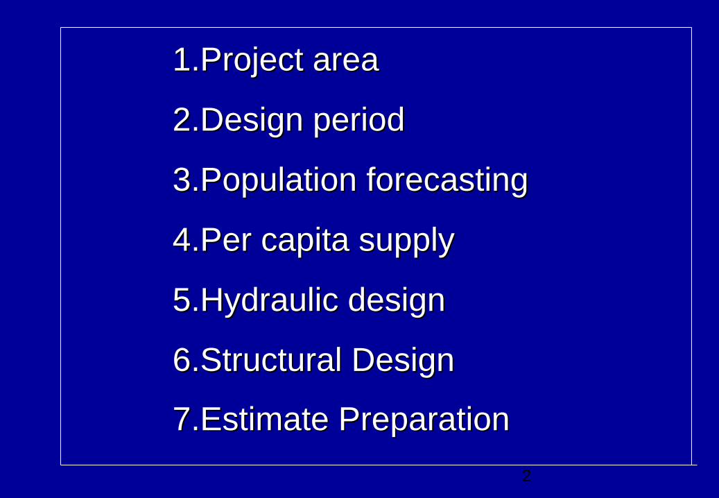
1.Project area1.Project area
2.Design period2.Design period
3.Population forecasting 3.Population forecasting
4.Per capita supply4.Per capita supply
5.Hydraulic design5.Hydraulic design
6.Structural Design6.Structural Design
7.Estimate Preparation7.Estimate Preparation

3
Project AreaProject Area
• Topography Topography
• Climate Climate
• CultureCulture
• MigrationMigration
• ReligionReligion
• Population patternPopulation pattern
• Economic & Social ConditionEconomic & Social Condition
4
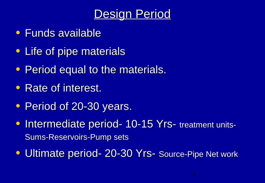
Design PeriodDesign Period
• Funds available Funds available
• Life of pipe materials Life of pipe materials
• Period equal to the materials.Period equal to the materials.
• Rate of interest.Rate of interest.
• Period of 20-30 years.Period of 20-30 years.
• Intermediate period- 10-15 Yrs- Intermediate period- 10-15 Yrs- treatment units-treatment units-
Sums-Reservoirs-Pump setsSums-Reservoirs-Pump sets
• Ultimate period- 20-30 Yrs- Ultimate period- 20-30 Yrs- Source-Pipe Net work Source-Pipe Net work

5
Population forecastingPopulation forecasting
The Design population will have to be estimated duly considering the The Design population will have to be estimated duly considering the
factors like future growth, development of the area factors like future growth, development of the area
Arithmetical increaseArithmetical increase method :(Pop increase decade to decade at method :(Pop increase decade to decade at
constant rate) low value constant rate) low value Pn = P +n.CPn = P +n.C
Geometrical IncreaseGeometrical Increase Method:(% increase in pop –decade to decade is Method:(% increase in pop –decade to decade is
constant) Higher value Pn = P(1+IG /100)constant) Higher value Pn = P(1+IG /100)nn
Incremental IncreaseIncremental Increase Method: This improvement over the above two Method: This improvement over the above two
methods .The average increase in the population is determined by the methods .The average increase in the population is determined by the
arithmetical method and to this is added the average of the net increment arithmetical method and to this is added the average of the net increment
increase once for future decade.increase once for future decade.
Graphical Method : Graphical Method : The population of last few decades are correctly The population of last few decades are correctly
plotted to a suitable scale on the graph with respect to decades. The curve plotted to a suitable scale on the graph with respect to decades. The curve
is smoothly extended to forecast the future population.is smoothly extended to forecast the future population.
6
Per capita DemandPer capita Demand
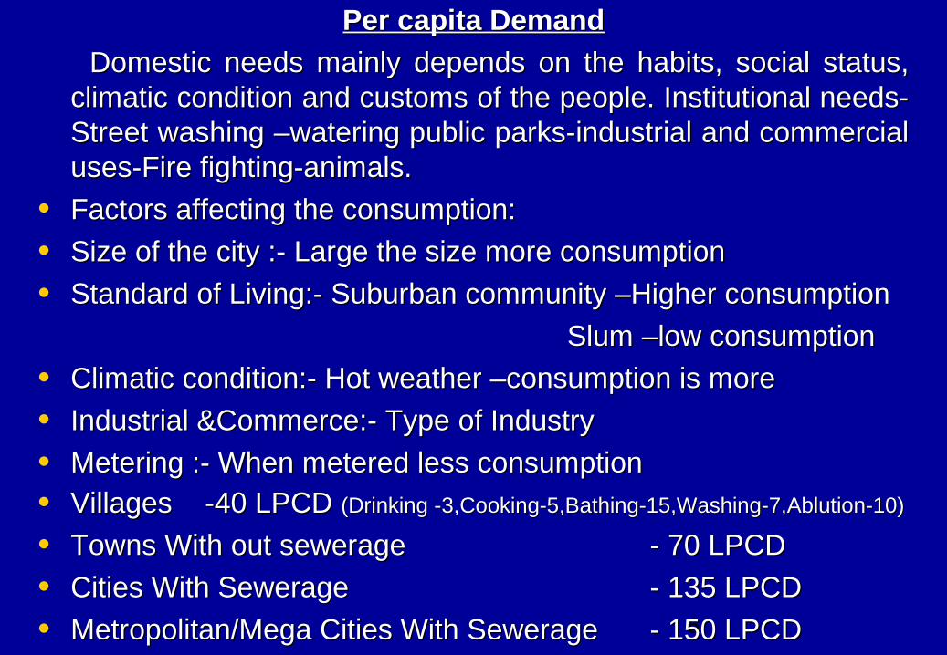
Domestic needs mainly depends on the habits, social status, Domestic needs mainly depends on the habits, social status, climatic condition and customs of the people. Institutional needs-climatic condition and customs of the people. Institutional needs-Street washing –watering public parks-industrial and commercial Street washing –watering public parks-industrial and commercial uses-Fire fighting-animals.uses-Fire fighting-animals.
• Factors affecting the consumption: Factors affecting the consumption:
• Size of the city :- Large the size more consumptionSize of the city :- Large the size more consumption
• Standard of Living:- Suburban community –Higher consumptionStandard of Living:- Suburban community –Higher consumption
Slum –low consumptionSlum –low consumption
• Climatic condition:- Hot weather –consumption is moreClimatic condition:- Hot weather –consumption is more
• Industrial &Commerce:- Type of IndustryIndustrial &Commerce:- Type of Industry
• Metering :- When metered less consumptionMetering :- When metered less consumption• Villages -40 LPCD Villages -40 LPCD (Drinking -3,Cooking-5,Bathing-15,Washing-7,Ablution-10)(Drinking -3,Cooking-5,Bathing-15,Washing-7,Ablution-10)
• Towns With out sewerageTowns With out sewerage - 70 LPCD- 70 LPCD
• Cities With SewerageCities With Sewerage - 135 LPCD- 135 LPCD
• Metropolitan/Mega Cities With SewerageMetropolitan/Mega Cities With Sewerage - 150 LPCD- 150 LPCD
77
Water supply scheme can be Water supply scheme can be divided in to three partsdivided in to three parts
• Source Source
• Head Works Head Works
• Transmission of waterTransmission of water
8
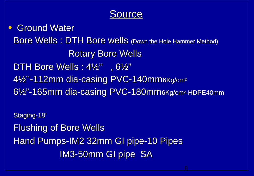
SourceSource• Ground Water Ground Water Bore Wells : DTH Bore wells Bore Wells : DTH Bore wells (Down the Hole Hammer Method)(Down the Hole Hammer Method)
Rotary Bore WellsRotary Bore Wells
DTH Bore Wells : 4½’’ , 6½” DTH Bore Wells : 4½’’ , 6½” 4½’’-112mm dia-casing PVC-140mm4½’’-112mm dia-casing PVC-140mm6Kg/cm6Kg/cm²²
6½”-165mm dia-casing PVC-180mm6½”-165mm dia-casing PVC-180mm6Kg/cm6Kg/cm²²-HDPE40mm-HDPE40mm
Staging-18’Staging-18’
Flushing of Bore WellsFlushing of Bore Wells
Hand Pumps-IM2 32mm GI pipe-10 PipesHand Pumps-IM2 32mm GI pipe-10 Pipes
IM3-50mm GI pipe SAIM3-50mm GI pipe SA
9
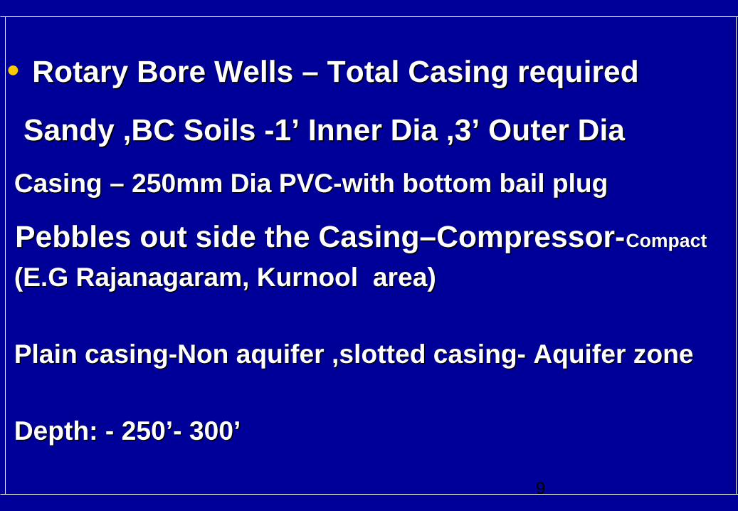
• Rotary Bore Wells – Total Casing requiredRotary Bore Wells – Total Casing required
Sandy ,BC Soils -1’ Inner Dia ,3’ Outer Dia Sandy ,BC Soils -1’ Inner Dia ,3’ Outer Dia
Casing – 250mm Dia PVC-with bottom bail plugCasing – 250mm Dia PVC-with bottom bail plug
Pebbles out side the Casing–Compressor-Pebbles out side the Casing–Compressor-CompactCompact
(E.G Rajanagaram, Kurnool area)(E.G Rajanagaram, Kurnool area)
Plain casing-Non aquifer ,slotted casing- Aquifer zonePlain casing-Non aquifer ,slotted casing- Aquifer zone
Depth: - 250’- 300’Depth: - 250’- 300’
10
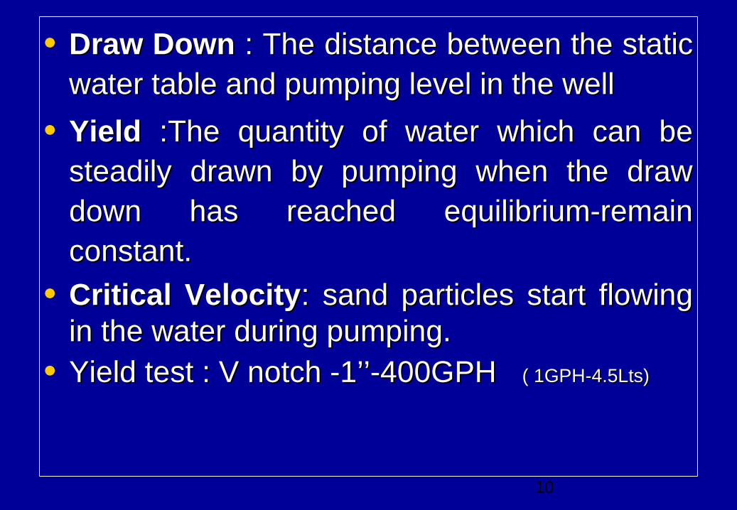
• Draw DownDraw Down : The distance between the static : The distance between the static water table and pumping level in the wellwater table and pumping level in the well
• YieldYield :The quantity of water which can be :The quantity of water which can be steadily drawn by pumping when the draw steadily drawn by pumping when the draw down has reached equilibrium-remain down has reached equilibrium-remain constant.constant.
• Critical VelocityCritical Velocity: sand particles start flowing : sand particles start flowing in the water during pumping.in the water during pumping.
• Yield test : V notch -1’’-400GPH Yield test : V notch -1’’-400GPH ( 1GPH-4.5Lts)( 1GPH-4.5Lts)
11
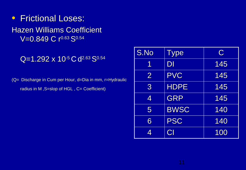
• Frictional Loses:Frictional Loses:Hazen Williams Coefficient Hazen Williams Coefficient
V=0.849 C rV=0.849 C r0.63 0.63 SS0.540.54
Q=1.292 x 10Q=1.292 x 10⁻⁵ -5 C d2.63 2.63 SS0.540.54
(Q=(Q= Discharge in Cum per Hour, d=Dia in mm, r=HydraulicDischarge in Cum per Hour, d=Dia in mm, r=Hydraulic radius in M ,S=slop of HGL , C= Coefficient)radius in M ,S=slop of HGL , C= Coefficient)
S.NoS.No TypeType CC
11 DIDI 145145
22 PVCPVC 145145
33 HDPEHDPE 145145
44 GRPGRP 145145
55 BWSCBWSC 140140
66 PSCPSC 140140
44 CICI 100100
12
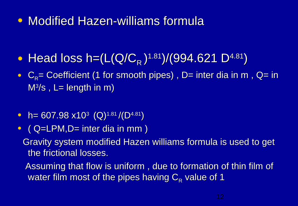
• Modified Hazen-williams formulaModified Hazen-williams formula
• Head loss h=(L(Q/CHead loss h=(L(Q/CR R ))1.811.81)/(994.621 D)/(994.621 D4.814.81))• CCRR= Coefficient (1 for smooth pipes) , D= inter dia in m , Q= in = Coefficient (1 for smooth pipes) , D= inter dia in m , Q= in
MM33/s , L= length in m)/s , L= length in m)
• h= 607.98 x10h= 607.98 x10³ 3 (Q) (Q)1.81 1.81 /(D/(D4.814.81))
• ( Q=LPM,D= inter dia in mm )( Q=LPM,D= inter dia in mm )
Gravity system modified Hazen williams formula is used to get Gravity system modified Hazen williams formula is used to get the frictional losses.the frictional losses.
Assuming that flow is uniform , due to formation of thin film of Assuming that flow is uniform , due to formation of thin film of water film most of the pipes having Cwater film most of the pipes having CRR value of 1 value of 1
13
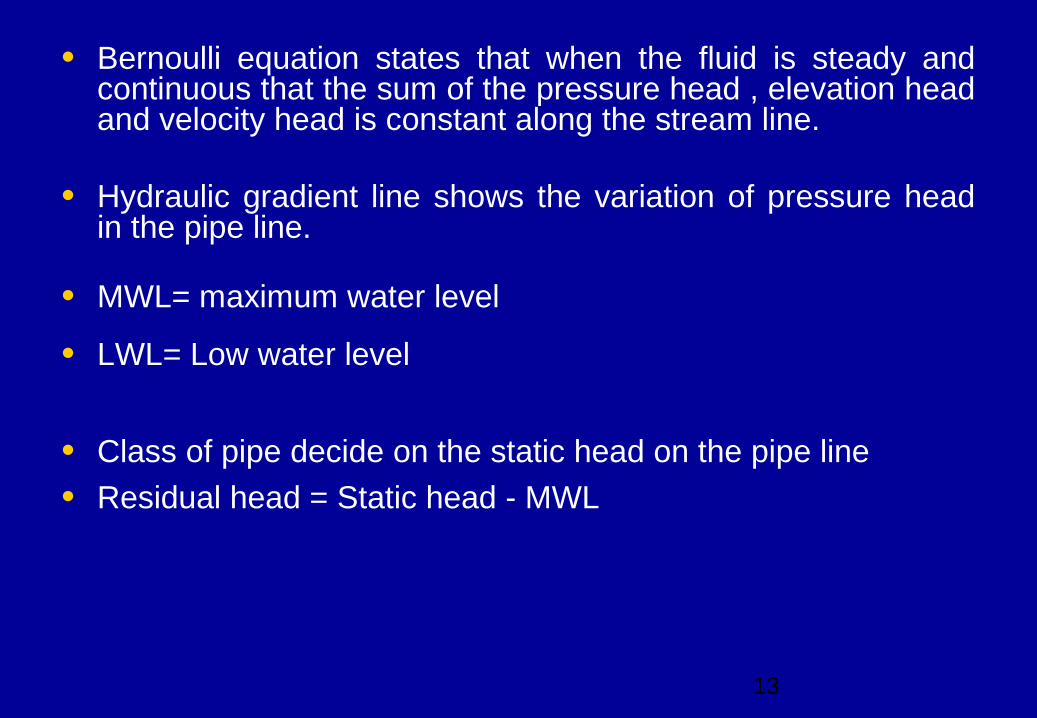
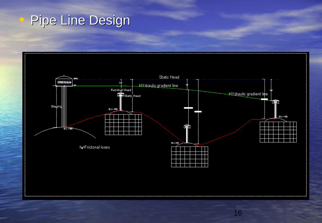
• Bernoulli equation states that when the fluid is steady and continuous that the sum of the pressure head , elevation head and velocity head is constant along the stream line.
• Hydraulic gradient line shows the variation of pressure head in the pipe line.
• MWL= maximum water level
• LWL= Low water level
• Class of pipe decide on the static head on the pipe line
• Residual head = Static head - MWL
14
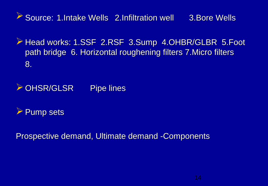
Source: 1.Intake Wells1.Intake Wells 2.Infiltration well2.Infiltration well 3.Bore Wells3.Bore Wells
Head works: 1.SSF 2.RSF 3.Sump 4.OHBR/GLBR 5.Foot Head works: 1.SSF 2.RSF 3.Sump 4.OHBR/GLBR 5.Foot path bridge 6. Horizontal roughening filters 7.Micro filterspath bridge 6. Horizontal roughening filters 7.Micro filters
8.8.
OHSR/GLSROHSR/GLSR Pipe lines Pipe lines
Pump sets Pump sets
Prospective demand, Ultimate demand -ComponentsProspective demand, Ultimate demand -Components
15
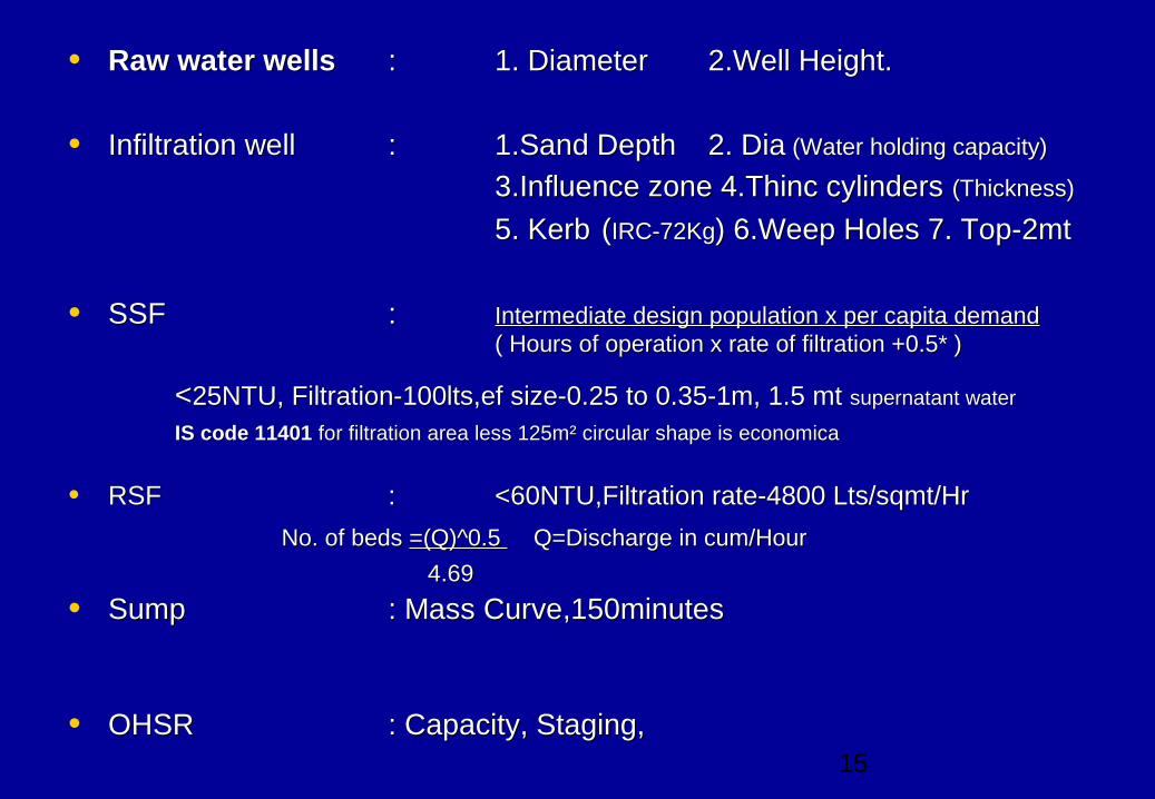
• Raw water wellsRaw water wells :: 1. Diameter 1. Diameter 2.Well Height.2.Well Height.
• Infiltration wellInfiltration well : : 1.Sand Depth 1.Sand Depth 2. Dia2. Dia (Water holding capacity) (Water holding capacity)
3.Influence zone 4.Thinc cylinders 3.Influence zone 4.Thinc cylinders (Thickness) (Thickness)
5. Kerb5. Kerb ((IRC-72KgIRC-72Kg) 6.Weep Holes 7. Top-2mt ) 6.Weep Holes 7. Top-2mt
• SSFSSF :: Intermediate design population x per capita demandIntermediate design population x per capita demand ( Hours of operation x rate of filtration +0.5* )( Hours of operation x rate of filtration +0.5* )
<<25NTU, Filtration-100lts,ef size-0.25 to 0.35-1m, 1.5 mt 25NTU, Filtration-100lts,ef size-0.25 to 0.35-1m, 1.5 mt supernatant watersupernatant water IS code 11401IS code 11401 for filtration area less 125m² circular shape is economica for filtration area less 125m² circular shape is economica
• RSFRSF : : <60NTU,Filtration rate-4800 Lts/sqmt/Hr<60NTU,Filtration rate-4800 Lts/sqmt/Hr
No. of beds No. of beds =(Q)^0.5 =(Q)^0.5 Q=Discharge in cum/Hour Q=Discharge in cum/Hour
4.694.69
• SumpSump : Mass Curve,150minutes: Mass Curve,150minutes
• OHSROHSR : Capacity, Staging, : Capacity, Staging,
16
• Pipe Line DesignPipe Line Design
17
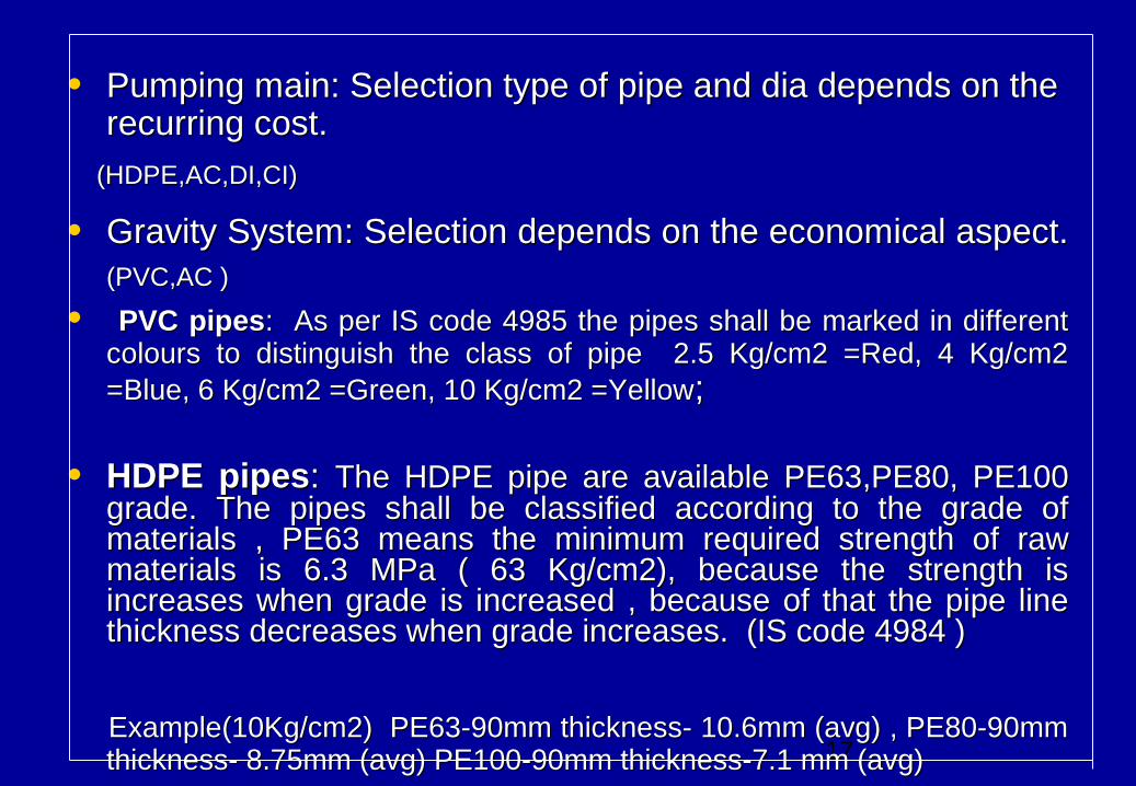
• Pumping main: Selection type of pipe and dia depends on the Pumping main: Selection type of pipe and dia depends on the recurring cost.recurring cost.
(HDPE,AC,DI,CI)(HDPE,AC,DI,CI)
• Gravity System: Selection depends on the economical aspect. Gravity System: Selection depends on the economical aspect. (PVC,AC )(PVC,AC )
• PVC pipesPVC pipes: As per IS code 4985 the pipes shall be marked in different : As per IS code 4985 the pipes shall be marked in different colours to distinguish the class of pipe 2.5 Kg/cm2 =Red, 4 Kg/cm2 colours to distinguish the class of pipe 2.5 Kg/cm2 =Red, 4 Kg/cm2 =Blue, 6 Kg/cm2 =Green, 10 Kg/cm2 =Yellow=Blue, 6 Kg/cm2 =Green, 10 Kg/cm2 =Yellow;;
• HDPE pipesHDPE pipes: : The HDPE pipe are available PE63,PE80, PE100 The HDPE pipe are available PE63,PE80, PE100 grade. The pipes shall be classified according to the grade of grade. The pipes shall be classified according to the grade of materials , PE63 means the minimum required strength of raw materials , PE63 means the minimum required strength of raw materials is 6.3 MPa ( 63 Kg/cm2), because the strength is materials is 6.3 MPa ( 63 Kg/cm2), because the strength is increases when grade is increased , because of that the pipe line increases when grade is increased , because of that the pipe line thickness decreases when grade increases. (IS code 4984 )thickness decreases when grade increases. (IS code 4984 )
Example(10Kg/cm2) PE63-90mm thickness- 10.6mm (avg) , PE80-90mm Example(10Kg/cm2) PE63-90mm thickness- 10.6mm (avg) , PE80-90mm thickness- 8.75mm (avg) PE100-90mm thickness-7.1 mm (avg)thickness- 8.75mm (avg) PE100-90mm thickness-7.1 mm (avg)
18
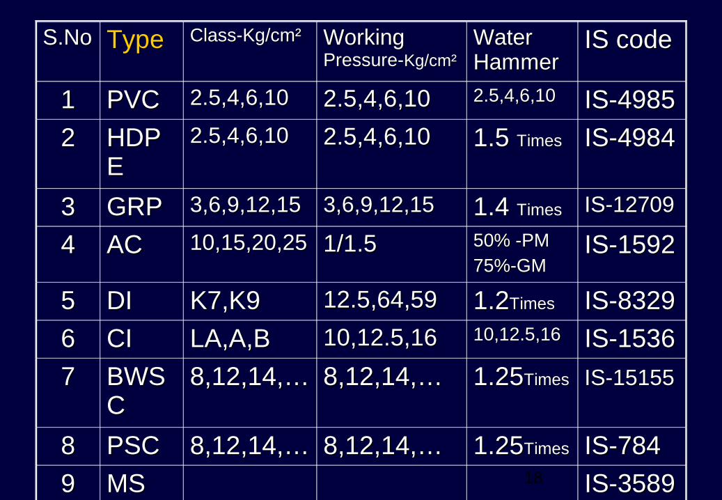
S.NoS.No TypeType Class-Kg/cm² Class-Kg/cm² Working Working Pressure-Pressure-Kg/cm²Kg/cm²
Water Water HammerHammer
IS codeIS code
11 PVCPVC 2.5,4,6,102.5,4,6,10 2.5,4,6,102.5,4,6,10 2.5,4,6,102.5,4,6,10 IS-4985 IS-4985
22 HDPHDPEE
2.5,4,6,102.5,4,6,10 2.5,4,6,102.5,4,6,10 1.5 1.5 TimesTimes IS-4984 IS-4984
33 GRPGRP 3,6,9,12,153,6,9,12,15 3,6,9,12,153,6,9,12,15 1.4 1.4 TimesTimes IS-12709 IS-12709
44 ACAC 10,15,20,2510,15,20,25 1/1.51/1.5 50% -PM50% -PM75%-GM75%-GM
IS-1592 IS-1592
55 DIDI K7,K9K7,K9 12.5,64,5912.5,64,59 1.21.2TimesTimes IS-8329 IS-8329
66 CICI LA,A,BLA,A,B 10,12.5,1610,12.5,16 10,12.5,1610,12.5,16 IS-1536 IS-1536
77 BWSBWSCC
8,12,14,…8,12,14,… 8,12,14,…8,12,14,… 1.251.25TimesTimes IS-15155IS-15155
88 PSCPSC 8,12,14,…8,12,14,… 8,12,14,…8,12,14,… 1.251.25TimesTimes IS-784 IS-784
99 MSMS IS-3589 IS-3589
19
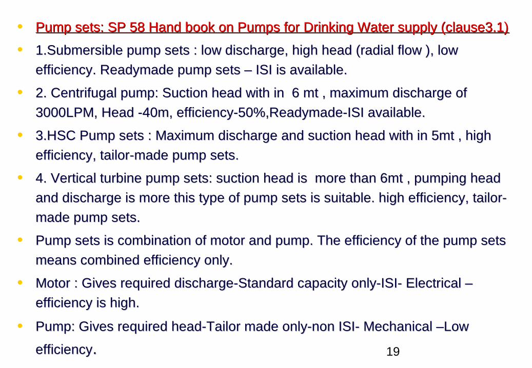
• Pump sets: SP 58 Hand book on Pumps for Drinking Water supply (clause3.1)Pump sets: SP 58 Hand book on Pumps for Drinking Water supply (clause3.1)
• 1.Submersible pump sets : low discharge, high head (radial flow ), low 1.Submersible pump sets : low discharge, high head (radial flow ), low
efficiency. Readymade pump sets – ISI is available.efficiency. Readymade pump sets – ISI is available.
• 2. Centrifugal pump: Suction head with in 6 mt , maximum discharge of 2. Centrifugal pump: Suction head with in 6 mt , maximum discharge of
3000LPM, Head -40m, efficiency-50%,Readymade-ISI available.3000LPM, Head -40m, efficiency-50%,Readymade-ISI available.
• 3.HSC Pump sets : Maximum discharge and suction head with in 5mt , high 3.HSC Pump sets : Maximum discharge and suction head with in 5mt , high
efficiency, tailor-made pump sets.efficiency, tailor-made pump sets.
• 4. Vertical turbine pump sets: suction head is more than 6mt , pumping head 4. Vertical turbine pump sets: suction head is more than 6mt , pumping head
and discharge is more this type of pump sets is suitable. high efficiency, tailor-and discharge is more this type of pump sets is suitable. high efficiency, tailor-
made pump sets.made pump sets.
• Pump sets is combination of motor and pump. The efficiency of the pump sets Pump sets is combination of motor and pump. The efficiency of the pump sets
means combined efficiency only. means combined efficiency only.
• Motor : Gives required discharge-Standard capacity only-ISI- Electrical –Motor : Gives required discharge-Standard capacity only-ISI- Electrical –
efficiency is high.efficiency is high.
• Pump: Gives required head-Tailor made only-non ISI- Mechanical –Low Pump: Gives required head-Tailor made only-non ISI- Mechanical –Low
efficiencyefficiency..
20
Trench sizeTrench size
Sand beddingSand bedding
Thrust BlocksThrust Blocks
Pipe line testingPipe line testing
Water HammerWater Hammer
21
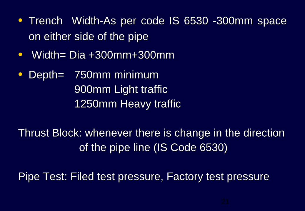
• Trench Width-As per code IS 6530 -300mm space Trench Width-As per code IS 6530 -300mm space
on either side of the pipeon either side of the pipe
• Width= Dia +300mm+300mmWidth= Dia +300mm+300mm
• Depth= Depth= 750mm minimum750mm minimum900mm Light traffic900mm Light traffic1250mm Heavy traffic1250mm Heavy traffic
Thrust Block: whenever there is change in the directionThrust Block: whenever there is change in the direction of the pipe line (IS Code 6530)of the pipe line (IS Code 6530)
Pipe Test: Filed test pressure, Factory test pressurePipe Test: Filed test pressure, Factory test pressure
22
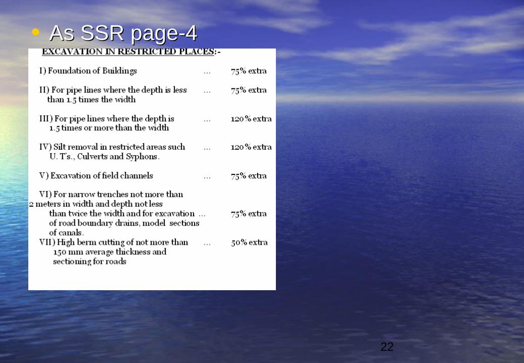
• As SSR page-4As SSR page-4
23
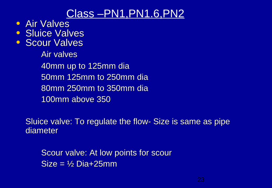
Class –PN1,PN1.6,PN2• Air ValvesAir Valves• Sluice ValvesSluice Valves• Scour ValvesScour Valves Air valvesAir valves
40mm up to 125mm dia40mm up to 125mm dia50mm 125mm to 250mm dia50mm 125mm to 250mm dia80mm 250mm to 350mm dia80mm 250mm to 350mm dia100mm above 350100mm above 350
Sluice valve: To regulate the flow- Size is same as pipe Sluice valve: To regulate the flow- Size is same as pipe diameter diameter
Scour valve: At low points for scourScour valve: At low points for scourSize = ½ Dia+25mmSize = ½ Dia+25mm
24
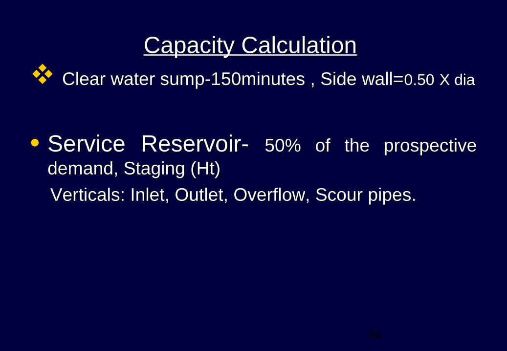
Capacity CalculationCapacity Calculation Clear water sump-150minutes , Side wall=Clear water sump-150minutes , Side wall=0.500.50 X diaX dia
• Service Reservoir- Service Reservoir- 50% of the prospective 50% of the prospective
demand, Staging (Ht) demand, Staging (Ht)
Verticals: Inlet, Outlet, Overflow, Scour pipes.Verticals: Inlet, Outlet, Overflow, Scour pipes.
25
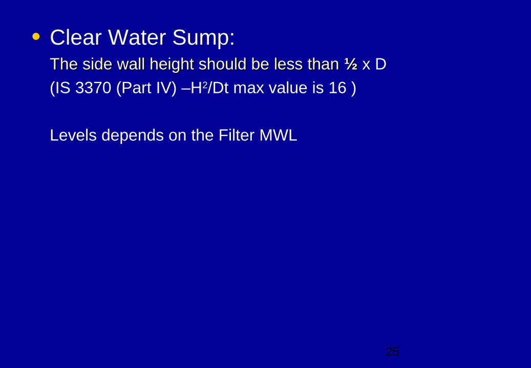
• Clear Water Sump:The side wall height should be less than The side wall height should be less than ½ ½ x D
(IS 3370 (Part IV) –H2/Dt max value is 16 )
Levels depends on the Filter MWL
26
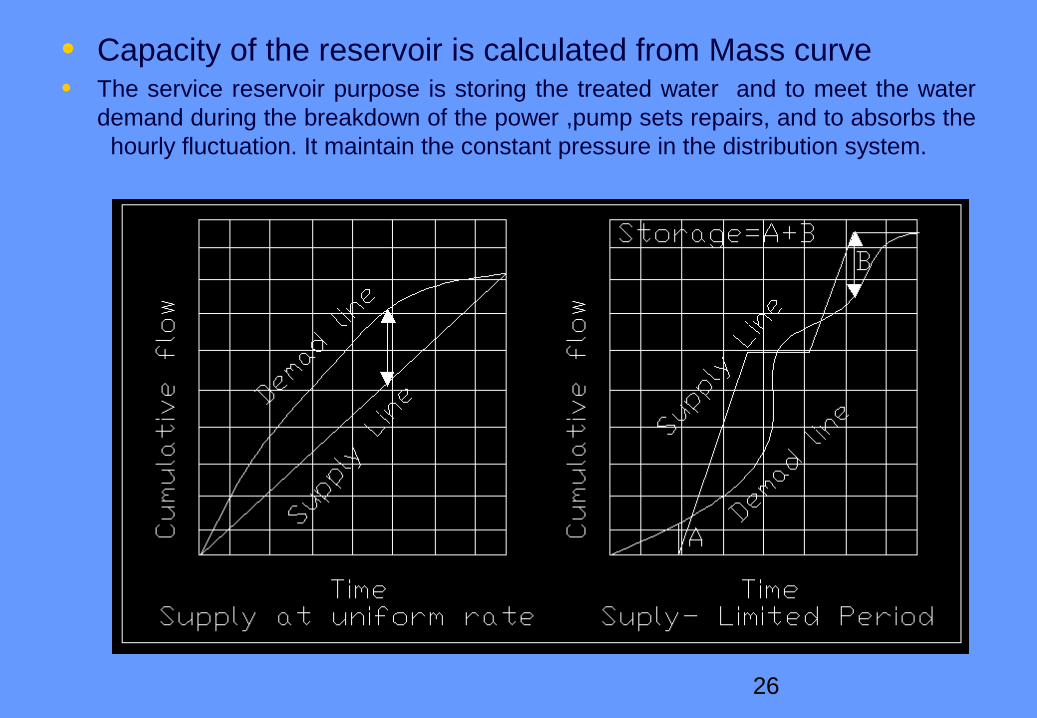
• Capacity of the reservoir is calculated from Mass curve• The service reservoir purpose is storing the treated water and to meet the water
demand during the breakdown of the power ,pump sets repairs, and to absorbs the hourly fluctuation. It maintain the constant pressure in the distribution system.
27
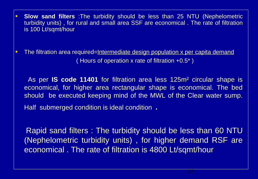
• Slow sand filtersSlow sand filters :The turbidity should be less than 25 NTU (Nephelometric :The turbidity should be less than 25 NTU (Nephelometric turbidity units) , for rural and small area SSF are economical . The rate of filtration turbidity units) , for rural and small area SSF are economical . The rate of filtration is 100 Lt/sqmt/houris 100 Lt/sqmt/hour
• The filtration area required=The filtration area required=Intermediate design population x per capita demandIntermediate design population x per capita demand
( Hours of operation x rate of filtration +0.5* )( Hours of operation x rate of filtration +0.5* )
As per As per IS code 11401IS code 11401 for filtration area less 125m² circular shape is for filtration area less 125m² circular shape is economical, for higher area rectangular shape is economical. The bed economical, for higher area rectangular shape is economical. The bed should be executed keeping mind of the MWL of the Clear water sump. should be executed keeping mind of the MWL of the Clear water sump.
Half submerged condition is ideal conditionHalf submerged condition is ideal condition . .
Rapid sand filtersRapid sand filters : The turbidity should be less than 60 NTU : The turbidity should be less than 60 NTU (Nephelometric turbidity units) , for higher demand RSF are (Nephelometric turbidity units) , for higher demand RSF are economical . The rate of filtration is 4800 Lt/sqmt/houreconomical . The rate of filtration is 4800 Lt/sqmt/hour
28
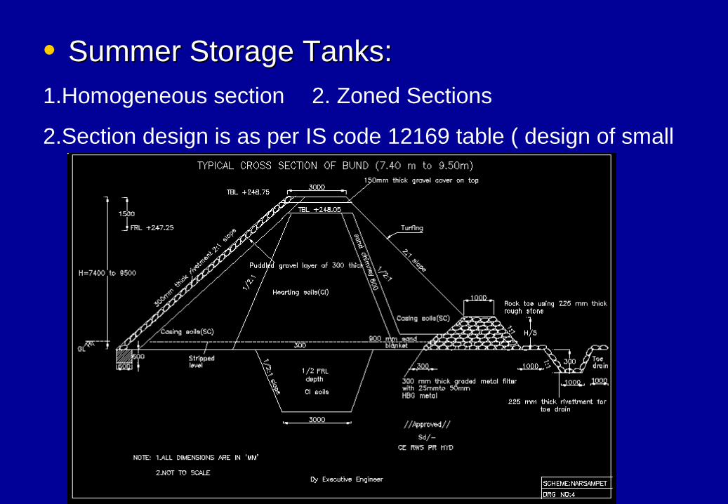
• Summer Storage Tanks: Summer Storage Tanks: 1.Homogeneous section 2. Zoned Sections
2.Section design is as per IS code 12169 table ( design of small
embankment section )
29
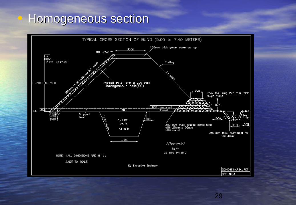
• Homogeneous sectionHomogeneous section
30
• Hydraulic statement for gravityHydraulic statement for gravity
• HGLHGL
• Static HeadStatic Head
• Class pipeClass pipe
• Residual HeadResidual Head
31
• Staging of Service reservoirStaging of Service reservoir
• Pipe Net workingPipe Net working
• Pumping mainPumping main
• Gravity mainGravity main
32
• Estimate PreparationEstimate Preparation• 1.Taxes will be Separated and provision are being made in
the general abstract against proof.
• Every month steel and cement and other rates will be
communicated by BOC
• Pipe rates will be modified w.r.t raw materials cost.
•
33
• 1.Maual on water supply and treatment -1.Maual on water supply and treatment -Central Central public health and Environmental engineering organization.public health and Environmental engineering organization.
• 2. Public Health Engineering-G.S.Bajwa ,Deep Publishers2. Public Health Engineering-G.S.Bajwa ,Deep Publishers
34
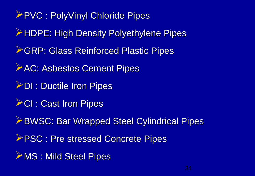
PVC : PolyVinyl Chloride PipesPVC : PolyVinyl Chloride Pipes
HDPE: High Density Polyethylene PipesHDPE: High Density Polyethylene Pipes
GRP: Glass Reinforced Plastic PipesGRP: Glass Reinforced Plastic Pipes
AC: Asbestos Cement PipesAC: Asbestos Cement Pipes
DI : Ductile Iron PipesDI : Ductile Iron Pipes
CI : Cast Iron PipesCI : Cast Iron Pipes
BWSC: Bar Wrapped Steel Cylindrical PipesBWSC: Bar Wrapped Steel Cylindrical Pipes
PSC : Pre stressed Concrete Pipes PSC : Pre stressed Concrete Pipes
MS : Mild Steel PipesMS : Mild Steel Pipes
35
• DisinfectionDisinfection : The use of Chlorine at various stages of water supply right from : The use of Chlorine at various stages of water supply right from raw water collection to distribution net work is common practice and term like pre raw water collection to distribution net work is common practice and term like pre chlorination and post chlorination. chlorination and post chlorination.
• Chlorine residualChlorine residual :-Satisfactory disinfection is obtained by prechlorination to :-Satisfactory disinfection is obtained by prechlorination to maintain 0.3 to 0.4 mg/l free available residual throughout treatment or 0.2 to 0.3 maintain 0.3 to 0.4 mg/l free available residual throughout treatment or 0.2 to 0.3 mg/l free available residual in the plant effluent at normal pH values. At higher pH mg/l free available residual in the plant effluent at normal pH values. At higher pH of 8 to 9 , at least 0.4mg/l is required for complete bacterial kill with 10 minutes of 8 to 9 , at least 0.4mg/l is required for complete bacterial kill with 10 minutes contact time. For 30 minutes contact time the dosage reduces to 0.2 to 0.3 mg/l contact time. For 30 minutes contact time the dosage reduces to 0.2 to 0.3 mg/l The normal concentration of chorine destroy the organism associated with typhoid The normal concentration of chorine destroy the organism associated with typhoid fever, dysenteries and various gastrointestinal disorders.fever, dysenteries and various gastrointestinal disorders.
• 1. Bleaching powder1. Bleaching powder• 2. Gas Chlorine2. Gas Chlorine
• 1. Belching powder: This is used for small quantities of water.Dosage is 2 ppm, 1. Belching powder: This is used for small quantities of water.Dosage is 2 ppm, Requirement per day Q = q x 2/106 Kg Where q is water demand is Liters per Requirement per day Q = q x 2/106 Kg Where q is water demand is Liters per day Generally for available chlorine in bleaching powder is 25% day Generally for available chlorine in bleaching powder is 25%
• = = Qx100Qx100 Kg Kg 2525
• 2. Gas Chlorine: This method is for large and medium public water supplies. 2. Gas Chlorine: This method is for large and medium public water supplies. It requires elaborate safety practice It requires elaborate safety practice
36
• Thrust BlocksThrust Blocks: When pipe line changes direction : When pipe line changes direction due to site condition there is possibility of horizontal due to site condition there is possibility of horizontal thrust will act, to over come this counter weight has thrust will act, to over come this counter weight has to be provided. Especially in pumping mains the to be provided. Especially in pumping mains the pressure in the pipe line are very high , so care pressure in the pipe line are very high , so care should be taken to provide thrust blocks other wise should be taken to provide thrust blocks other wise pipe will lift up.pipe will lift up.
• Horizontal thrust force=2 x p x A x sin /2 βHorizontal thrust force=2 x p x A x sin /2 βTonnesTonnes
• A= Cross sectional area of the pipe line in cm; P= A= Cross sectional area of the pipe line in cm; P= Pressure I the pipe line in Kg/cm2Pressure I the pipe line in Kg/cm2


![[WorldBank] Qualitative Data](https://static.fdocuments.us/doc/165x107/577c7b911a28abe05497f7cb/worldbank-qualitative-data.jpg)
