Water supply by rural builders
83
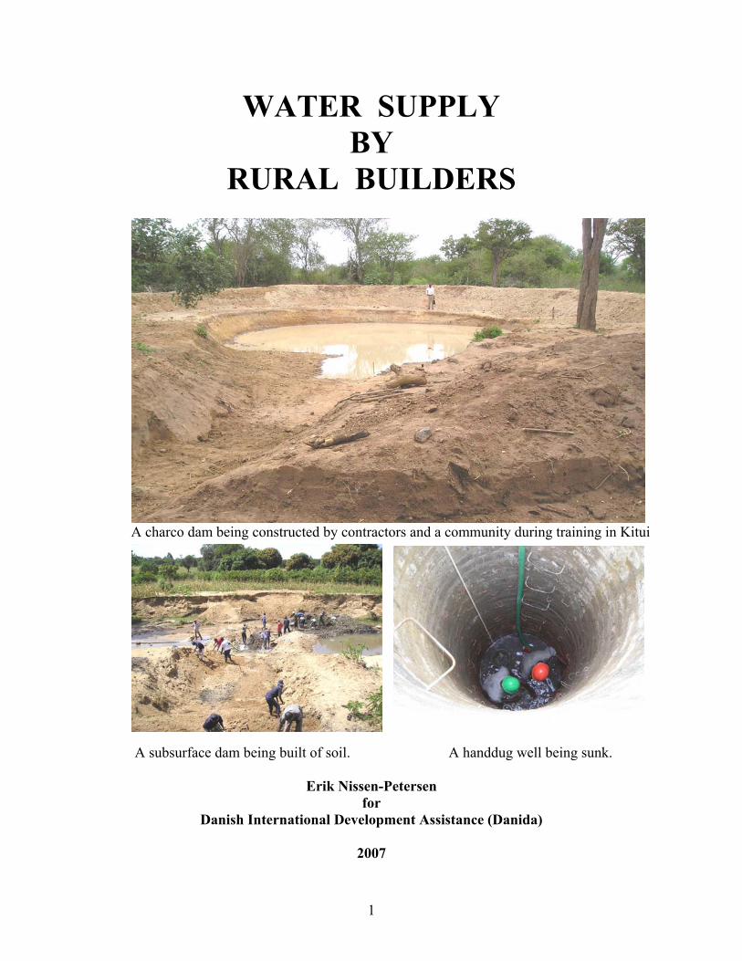
1 WATER SUPPLY BY RURAL BUILDERS A charco dam being constructed by contractors and a community during training in Kitui A subsurface dam being built of soil. A handdug well being sunk. Erik Nissen-Petersen for Danish International Development Assistance (Danida) 2007
-
Upload
stephen-musimba -
Category
Technology
-
view
1.947 -
download
1
Transcript of Water supply by rural builders
1
WATER SUPPLY BY
RURAL BUILDERS
A charco dam being constructed by contractors and a community during training in Kitui
A subsurface dam being built of soil. A handdug well being sunk.
Erik Nissen-Petersen
for Danish International Development Assistance (Danida)
2007

2

3
WATER SUPPLY BY
RURAL BUILDERS
A charco dam being constructed by contractors and a community during training in Kitui
A subsurface dam being built of soil. A handdug well being sunk.
Erik Nissen-Petersen
for Danish International Development Assistance (Danida)
2007

4

5
6
7
8

9

10

11
Chapter 1. Introduction 1.1 Purpose of this publication Builders in rural areas have for many years constructed water supply systems, such as roof gutters and water tanks for catchment of rainwater, handdug wells, subsurface dams, weirs, sand dams, ponds and small earth dams. The clients have either been individuals, non-governmental organizations (NGOs), government ministries, or donors such as Danida, Sida and UNDP. Many of these water projects function well and supply water, and, according to the water-users, do so without problems. However, some water projects do not function very well, while others are complete failures, and the reasons are a mixture of insufficient knowledge about surveying, design drawings, estimating bills of quantities, and costing accurately, as well as inadequate training of technicians and contractors, and improper operation and maintenance by the water users. This handbook, Water Supply by Rural Builders, is the 8th in a series of handbooks that gives guidelines on how to carry out simple, yet adequate, surveys, designs and construction of basic water projects. It is the popular belief that deep boreholes and large earth dams, built by heavy machinery, are the only two solutions to get water in arid and semi-arid lands (= the ASALs). The fact is, that a subsurface dam, built cheaply of soil in a riverbed and with a handdug well in the riverbank, can supply much more water and at a fraction of the cost compared to e.g. a deep borehole equipped with a submersible pump powered by a diesel generator. It is hoped that this handbook, and the whole series of 8 handbooks, will reduce the number of failed and under-performing water projects, and will reduce the significant amounts of money and man-hours wasted on costly, over-designed water projects, whose yields of water could be achieved by applying simple, low-cost, design and construction criteria, with lower operation and maintenance costs. Engineers do not learn the simple techniques required for low-cost water structures, such as they are described in these handbooks. It is therefore very timely that two university lecturers now produce textbooks, for use at universities and colleges, on community water projects. The world is running out of fresh water, partly due to over-exploitation of ground water resources by boreholes, and by contamination of the water in rivers and lakes. In the very near future, the only fresh water source may be the rains, at least where it is not acid due to pollution. Rainwater harvesting is a viable, sustainable and long-term solution, if applied properly, and it is hoped that this series of handbooks can also assist in promoting education on rainwater harvesting and self-reliance in water supply systems, while also improving the environment.

12
1.2 Rural water projects People living in the ASAL areas of the world must fetch water from the nearest water source, perhaps being 10 to 15 km away. Where water sources are further away than that, it may take several days to transport water by donkey or camel. Individuals and communities therefore find it very frustrating when they have worked hard and contributed cash to build a water project, and then find that it cannot supply sufficient water to cover the demand, or even worse, that it cannot supply any water at all. The Ministry of Water and Irrigation in Kenya reports that only 60% of drilled boreholes, costing an average of Ksh 850,000 each, are successful. Many hand dug wells are also sunk in wrong locations where water is brackish or non-existent. Sand dams, which raise the level of sand and water several metres in riverbeds, have a failure rate of around 90%. Earth dams are also problematic, as dam reservoirs get silted up and dam walls and spillways are washed away more often, probably due to global warming, and even some dams that have withstood heavy rainfall over the last 50 years have recently been washed away. This series of handbooks intends to give practical guidelines to show technicians and rural builders how to use simple technologies to design and construct water supply systems, with far more success than has been witnessed over the last three decades. It is hoped that the technical drawings presented on the following pages can be understood by laymen, while still being of a standard approvable by the authorities. The technical drawings are shown in millimetres (mm), centimetres (cm) and metres (m). Since laymen and rural builders in many countries are used to imperial measurements, these are shown in brackets as (”) for inches and (’) for feet, although some of the text also relates to inches and feet, where this was found to be appropriate. Engineers may also find this arrangement useful when they explain measurements to rural builders and farmers. Additional conversion tables are shown on page viii. The designs presented in this publication are shown in two chapters: Chapter 5 deals with construction works that local builders may build without approval by the authorities, while Chapter 6 presents structures for water supply that must be approved by the authorities before any construction works take place.
13
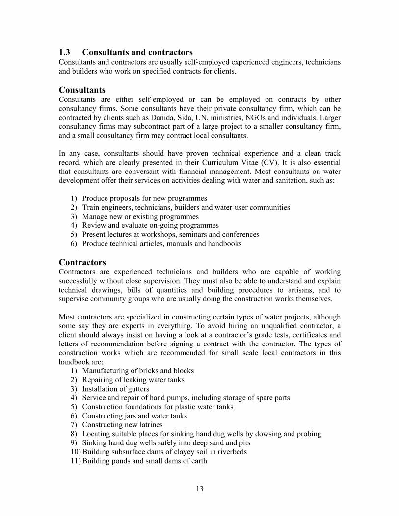
1.3 Consultants and contractors Consultants and contractors are usually self-employed experienced engineers, technicians and builders who work on specified contracts for clients. Consultants Consultants are either self-employed or can be employed on contracts by other consultancy firms. Some consultants have their private consultancy firm, which can be contracted by clients such as Danida, Sida, UN, ministries, NGOs and individuals. Larger consultancy firms may subcontract part of a large project to a smaller consultancy firm, and a small consultancy firm may contract local consultants. In any case, consultants should have proven technical experience and a clean track record, which are clearly presented in their Curriculum Vitae (CV). It is also essential that consultants are conversant with financial management. Most consultants on water development offer their services on activities dealing with water and sanitation, such as:
1) Produce proposals for new programmes 2) Train engineers, technicians, builders and water-user communities 3) Manage new or existing programmes 4) Review and evaluate on-going programmes 5) Present lectures at workshops, seminars and conferences 6) Produce technical articles, manuals and handbooks
Contractors Contractors are experienced technicians and builders who are capable of working successfully without close supervision. They must also be able to understand and explain technical drawings, bills of quantities and building procedures to artisans, and to supervise community groups who are usually doing the construction works themselves. Most contractors are specialized in constructing certain types of water projects, although some say they are experts in everything. To avoid hiring an unqualified contractor, a client should always insist on having a look at a contractor’s grade tests, certificates and letters of recommendation before signing a contract with the contractor. The types of construction works which are recommended for small scale local contractors in this handbook are:
1) Manufacturing of bricks and blocks 2) Repairing of leaking water tanks 3) Installation of gutters 4) Service and repair of hand pumps, including storage of spare parts 5) Construction foundations for plastic water tanks 6) Constructing jars and water tanks 7) Constructing new latrines 8) Locating suitable places for sinking hand dug wells by dowsing and probing 9) Sinking hand dug wells safely into deep sand and pits 10) Building subsurface dams of clayey soil in riverbeds 11) Building ponds and small dams of earth

14
1.4 Employed versus self-employed Employees’ constraints Most employed people find that their salaries can hardly pay for their daily expenses and that they have no possibility to increase their financial prosperity above that low survival level. Such people often think that if they could be self-employed they would earn more and increase their living standard. Another constraint for employees is that they must travel to and from work every working day. Traveling by public means is expensive and time consuming. Employees are often blamed by their employer for arriving too late at work in the mornings. Family problems may also arise when employees come home late after work. Employees being harassed at work and, perhaps, also at home for always being late, tired or absent-minded are nearly always looking for a chance to be self-employed. They dream of being their own boss who decides when and where to work with the kind of work they like. They also look forward to take a few working days off to attend private functions or to see the family back home in the rural area. Imagine not having a harsh Construction Foreman or a Manager whom you have to ask for permission to leave work for just a couple of hours! Disadvantage of being self-employed The personal freedom expected by being self-employed may turn out to be many daily working hours and busy weekends with telephone calls at any hour. Time for keeping accounts and preparing quotations or proposals may only be found during weekends and public holidays. Many non-paid working hours have to be spent on talking with potential customers who want to know the cost of this or that. Disappointingly often, such quotations turn out to be a waste of time, because somebody else is given the work for a lower price than that quoted. It costs money to start up a private business, because tools, a computer, machinery or a motor vehicle have to be bought. There is also rent to pay for office or workshop as well as monthly bills for electricity, water, security, VAT, insurance etc. Such financial demands can be stretched over a long period if a business is started up as a spare time activity partly financed by the owner’s salary as an employee, and partly by the business. Another way of learning how to start a business is be an employee or an associate of a contractor who is doing well. Although the pay may be small, it could be a good learning process.
15
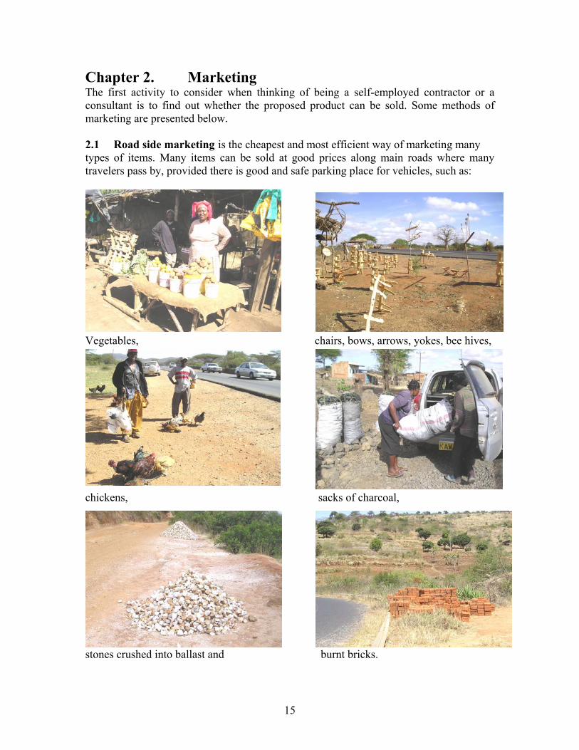
Chapter 2. Marketing The first activity to consider when thinking of being a self-employed contractor or a consultant is to find out whether the proposed product can be sold. Some methods of marketing are presented below. 2.1 Road side marketing is the cheapest and most efficient way of marketing many types of items. Many items can be sold at good prices along main roads where many travelers pass by, provided there is good and safe parking place for vehicles, such as:
Vegetables, chairs, bows, arrows, yokes, bee hives,
chickens, sacks of charcoal,
stones crushed into ballast and burnt bricks.

16
2.2 Posters and notices are other cheap methods of marketing the sale of goods and the provision of services. Hand written or printed notices pinned onto trees and telephone poles situated along roads with many passers-by are effective messengers.
Notice boards in shopping centres, as seen below, and at public offices, also provide excellent marketing opportunities. However, ask for permission before pinning anything on a notice board because there might be a small fee to pay every week or month.
The uneven bottoms seen on the notices pinned to the notice board in a shopping centre above, are strips of papers with telephone numbers which can be pulled off by interested persons who want to phone for further details at a later stage.

17
2.3 Signboards are usually painted in bright colours with an arrow pointed to e.g. a hair saloon, which is situated a short walking distance from the road.
Often several signboards are required to guide customers to a location which is situated behind several buildings or around some corners. Although a signboard may not be expensive to make, there might be a fee to pay to the local county council, and a signboard needs to be maintained, such as repainting due to graffiti or the weather.
While a good signboard set up in a right place might bring many customers, it is doubtful whether a good signboard can attract clients if it is set up among many signboards. Signboards have to be repainted once or twice annually to appear attractive and to show that the business is active and doing good business. This signboard, offering repair of motor vehicles along a main road, can only attract motorists whose vehicles have a total break down just before sunset!
18
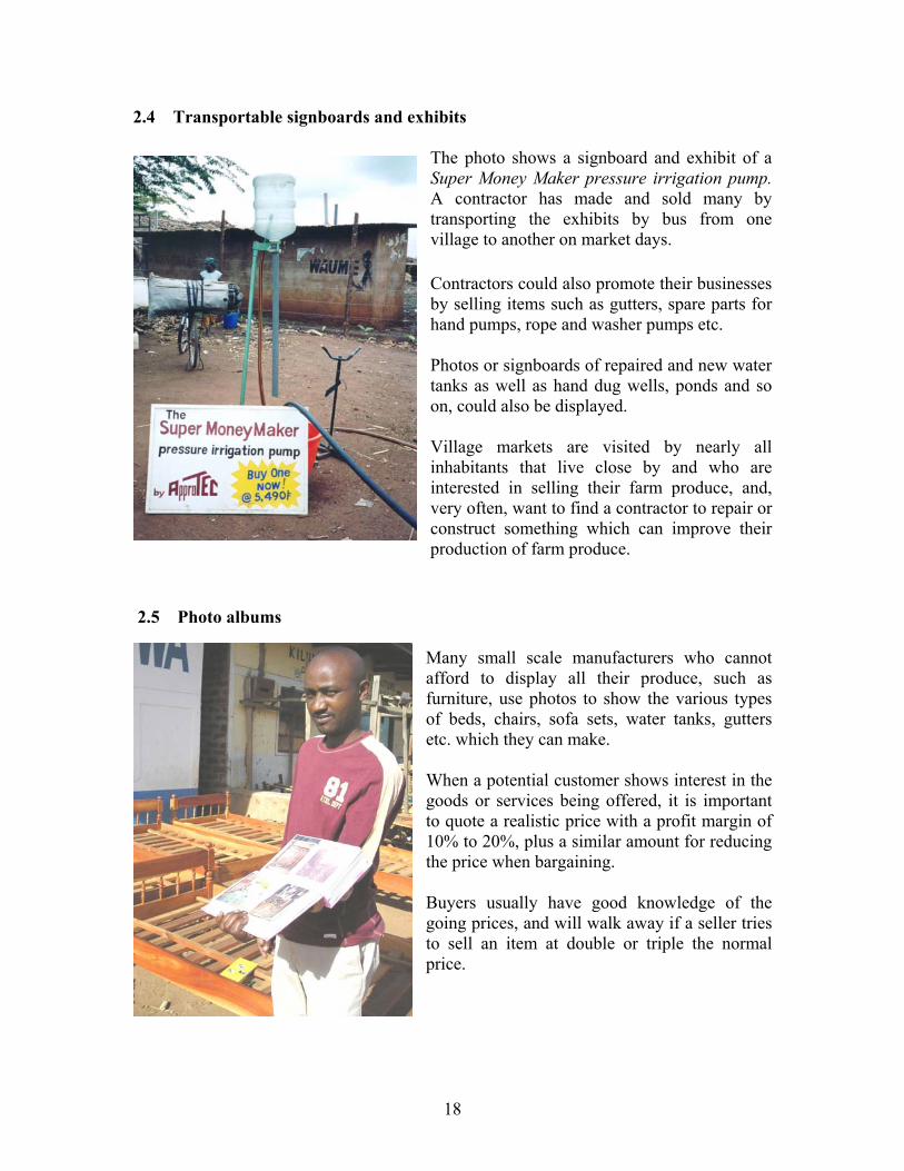
2.4 Transportable signboards and exhibits
The photo shows a signboard and exhibit of a Super Money Maker pressure irrigation pump. A contractor has made and sold many by transporting the exhibits by bus from one village to another on market days. Contractors could also promote their businesses by selling items such as gutters, spare parts for hand pumps, rope and washer pumps etc. Photos or signboards of repaired and new water tanks as well as hand dug wells, ponds and so on, could also be displayed. Village markets are visited by nearly all inhabitants that live close by and who are interested in selling their farm produce, and, very often, want to find a contractor to repair or construct something which can improve their production of farm produce.
2.5 Photo albums
Many small scale manufacturers who cannot afford to display all their produce, such as furniture, use photos to show the various types of beds, chairs, sofa sets, water tanks, gutters etc. which they can make. When a potential customer shows interest in the goods or services being offered, it is important to quote a realistic price with a profit margin of 10% to 20%, plus a similar amount for reducing the price when bargaining. Buyers usually have good knowledge of the going prices, and will walk away if a seller tries to sell an item at double or triple the normal price.
19
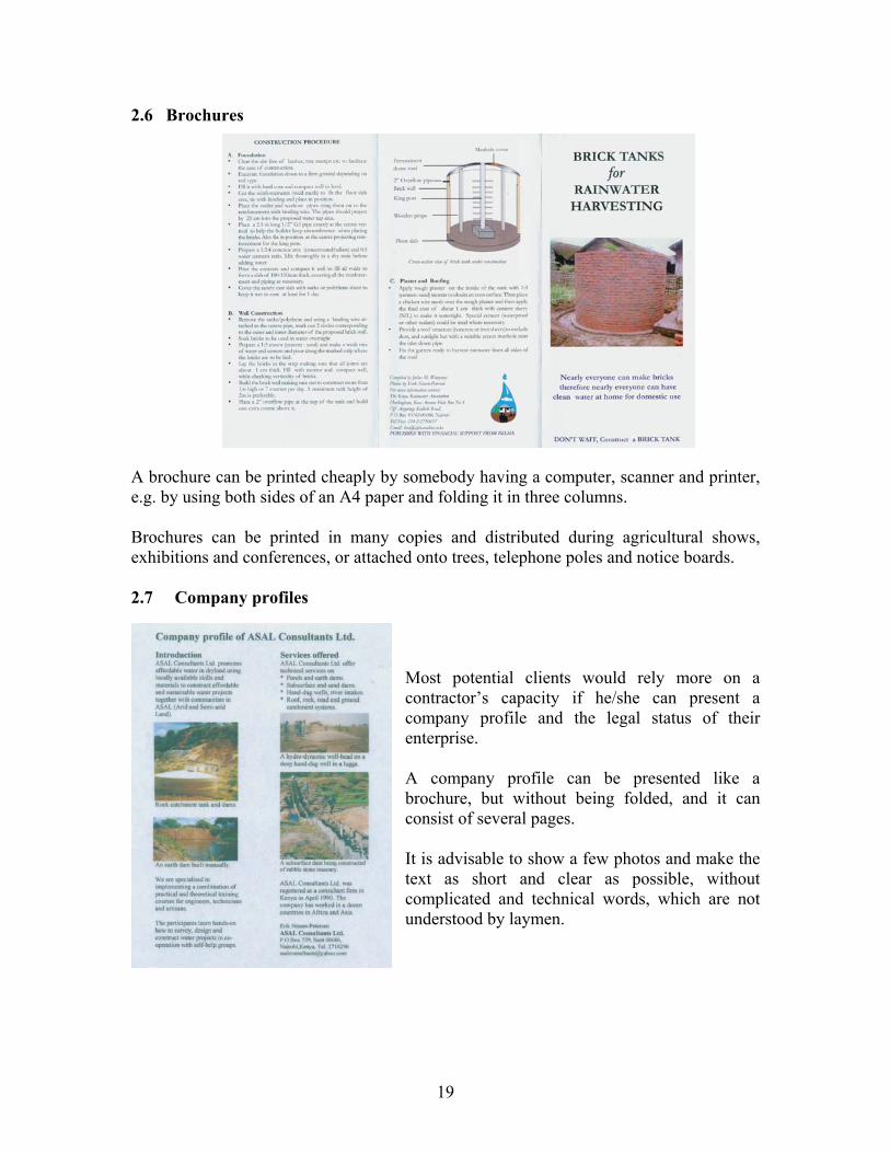
2.6 Brochures A brochure can be printed cheaply by somebody having a computer, scanner and printer, e.g. by using both sides of an A4 paper and folding it in three columns. Brochures can be printed in many copies and distributed during agricultural shows, exhibitions and conferences, or attached onto trees, telephone poles and notice boards. 2.7 Company profiles
Most potential clients would rely more on a contractor’s capacity if he/she can present a company profile and the legal status of their enterprise. A company profile can be presented like a brochure, but without being folded, and it can consist of several pages. It is advisable to show a few photos and make the text as short and clear as possible, without complicated and technical words, which are not understood by laymen.

20
2.8 Letters of Recommendation Always remember to request satisfied customers to write a Letter of Recommendation, which can be shown as proof of a contractor’s skills and capacity to potential customers. Recommendation letters should contain a description of the services rendered and the customers name and mobile number. Letters of Recommendation can also be written as shown in the following:
TO WHOM IT MAY CONCERN This is to certify that M/rs ………………….. worked for this company as a Construction Supervisor on small scale water projects in Eastern Province of Kenya from 1st March 2007 to 2nd November 2007. Mr/s ……………. has cooperated well with his/her colleagues, has taken his/her work seriously and performed with integrity. His/her personal conduct is polite and humble. Due to the closure of the small scale water project, Mr/s …………… employment will end on 2nd November this year. Yours faithfully, …………………………… Managing Director 2.9 Curriculum Vitae (CV) CVs are required when applying for employment, but are also useful to show to potential clients who want to know what a contractor can do. CVs are usually presented as follows:
Curriculum Vitae
Name: Address: Email: Telephone: Sex: Marital status: Date of birth Nationality: Professional Field Technical institutions attended Academic year Institution Grade/Qualifications Referees Name Position Telephone number Attach only photocopies of certificates, diplomas, Letters of Recommendation, ID cards, passport photos etc. to applications. Do not ask for your copies to be returned, because employers are busy people who do not want to waste their time on unnecessary tasks.

21
Chapter 3. Agreements and contracts 3.1 Verbal agreements Verbal agreements on the provision of labour between a client and a contractor are the most used method for contracting smaller construction jobs, such as making bricks, concreting foundations, building and plastering walls, and making roofs for water tanks and houses. Normally, the client supplies all the required materials while the contractor brings his tools and equipment. If the contractor comes from far, the client may provide bus fares, food and accommodation in addition to an agreed payment. Such payments are based on a daily salary of about Ksh 500 for the number of working days that the two parties shall agree on. A down payment of 10% to 20% of the total payment is normal when a verbal agreement is made “so that the contractor’s wife can buy food while her husband is going to be away”. Since some clients tend to delay, or even neglect, agreed-upon payment rates, contractors have to ask for the agreed payment rates due to “very urgent matters with the wife and kids at home”. One of the reasons why a client may delay payments to a contractor is that, if the contractor is paid too much up front, the contractor may disappear from work and perhaps for good. Another reason for clients to delay payments is to find out whether e.g. a water tank will develop leakages when full of water. Local contractors can only give a verbal warranty for their work and they are very reluctant to repair their work without extra payment. Dishonestly, some clients never intend to pay the last installment to a contractor, because the contractor cannot bring the case to court due to lack of evidence, such as a written contract. 3.2 Contracts To avoid such problems, it is recommended that a client and his contractor should write a simple contract. Such a contract should state the scope of work and payment rates for the work, such as: down payment, payment rates and a retention fee, which will be paid when the completed structure has functioned for 90 days without problems. Contracts should also state whether 5% withholding tax shall be deducted from monthly salaries exceeding Ksh 24,000. It is also important to state whether the client or the contractor shall pay for the contractor’s medical expenses in case of accidents or sickness during his work for the client. Should a problem arise between a client and his contractor, both or one of them can present the contract to the Locational Chief for a settlement. Should the chief refuse to handle the case, it can be brought either to an advocate or to the chief’s superior, the District Officer.

22
A contract could be written as follows:
3.3 CONTRACT FOR CONSTRUCTION OF …………………. This is a contract between ……………………, P.O. Box ….., ………….Tel…….., hereafter called The Client, and M.. ……….……….., ID number………….. , P.O. Box …., ……….…, Tel. …………, hereafter called the The Contractor, who shall construct …………………………………for which the design has been approved by the Ministry of Water and Irrigation (MoWI) and which is described below: Detailed description of the work to be carried out by the Contractor is as follows: 1) 2) 3) 4) 5) 6) The Contractor is not an employee of the Client. Therefore no other benefits or compensation than the fee stated below will be provided. The Contractor is responsible for paying his and his employees’ taxes, telephone, stationeries, office facilities, bus fares, accommodation, medical expenses and all other costs that he may incur in connection with this contract. The Client shall pay the Contractor for the services listed above, as follows: A total of Ksh ……..… as follows: Ksh ……… upon signing this contract. Ksh …..…… when the work has been approved by the MoWI and they have issued a Completion Certificate to the Client. Ksh …………. shall be paid as retention fee when the structure has functioned without problems for 90 days after the Completion Certificate was issued. Monthly payments exceeding Ksh 24,000 shall be deducted 5% withholding tax, which the client shall submit by cheque to the Collector of Income Tax before the 20th of the following month. On this we agree .…/…./…. (day/month/year) ……………………………………. ……………………………………. The Contractor The Client

23
3.4 Design and permit for construction of water projects It is the clients’ responsibility to obtain a design and get it approved by the relevant authorities. Whether the proposed project belongs to an individual or a community, it is recommended to contract a water engineer or technician to carry out an evaluation of the project area to find the most potential site in the project area and to draw and design it. Engineers and technicians can also produce a list, called a Bill of Quantities (BQ), with the required working days and materials for the designed project. BQs are used by clients to find the actual construction cost of a designed structure by requesting for quotations from various hardware shops and contractors. Clients are not bound to accept the cheapest quotation, but they will also consider who is most capable of carrying out the task, among others from the contractors’ track records. Applications for water permits must be sent or taken to MoWI and should contain the following: A design drawing in A1 format showing a Plan, a Longitudinal Profile, one or more Cross Sections, a map sketch and a text box in A1 format as shown below. For private water projects the owner should produce an Application Letter with photocopies of his/her Title Deed with its clauses. For community water projects, the project committee should apply with an Application Letter, photocopy of Title Deed with its clauses, a Land Agreement between the owner and the community on the access and usage of the water source, a Registration Certificate with the Department of Social Services and an Implementation Agreement or a contract with the consultant or contractor who designed the project and shall construct it.
24
Applications are presented to the nearest office of the MoWI for its approval and submitting it to the Water Resource Management Authority (WRMA) for their approval and assessment of annual fees on behalf of the local Water Services Board (WSB). The annual fee varies for according to the type of water projects. The Water Act of 2002 is now being applied by MOWI through: 3.5 Water Services Trust Fund Their headquarters are situated on 2nd floor, Mara Road, Upper Hill, P.O. Box 49699 – 00100, Nairobi. Tel. 2720696, fax 2723457, email [email protected] In an advert in Daily Nation on 22/11/07, the Trust Fund announced that is has funded 131 water projects by October 2007 and that 47 of these projects have been completed, while 60 projects are on-going. The value of the projects funded is Ksh 1.048 billion and the target population is 1,077,000 people. 3.6 Water Services Boards The Water Act of 2002 in Kenya is now being applied through 7 Water Services Boards (WSBs). Applications for construction and rehabilitation of water projects should be submitted to the appropriate Water Services Board on the following address:
Athi Water Services Board, P.O. Box 45283, 00100 Nairobi Tana Water Services Board, P.O. Box 1343, Nyeri Coast Water Services Board, P.O. Box 90417, 80100 Mombasa Lake Victoria South Water Services Board, P.O. Box 3325, Kisumu Lake Victoria North Water Services Board, P.O. Box 673, Kakamega Rift Valley Water Services Board, P.O. Box 220, Nakuru Northern Water Services Board, P.O. Box 495, Garissa
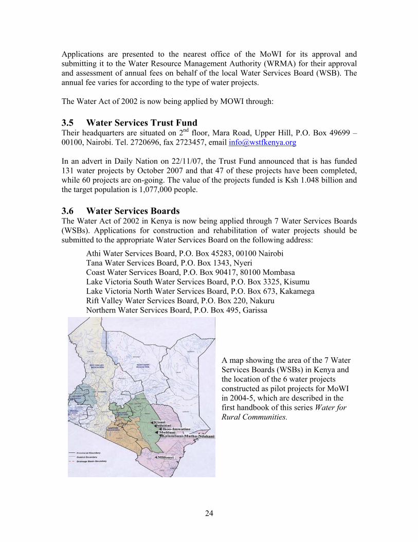
A map showing the area of the 7 Water Services Boards (WSBs) in Kenya and the location of the 6 water projects constructed as pilot projects for MoWI in 2004-5, which are described in the first handbook of this series Water for Rural Communities.
25
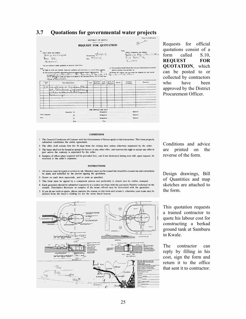
3.7 Quotations for governmental water projects Requests for official quotations consist of a form called S.10, REQUEST FOR QUOTATION, which can be posted to or collected by contractors who have been approved by the District Procurement Officer. Conditions and advice are printed on the reverse of the form. Design drawings, Bill of Quantities and map sketches are attached to the form. This quotation requests a trained contractor to quote his labour cost for constructing a berkad ground tank at Samburu in Kwale. The contractor can reply by filling in his cost, sign the form and return it to the office that sent it to contractor.
26
3.8 Proposals A proposals is made by a contractor with the hope of getting a contract for his/her services and expertise, and the proposal will describe the method and inputs that the contractor intends to use, and the price. Proposals must therefore be written in a clear and transparent way, which can convince potential clients. A potential client may request a couple of contractors or consultants to write and present a proposal, e.g.on conducting a training course or sinking a hand dug well. The client will compare the quotations and select the proposal that they consider to be the most appropriate and realistic, and that is competitive price wise. The client will usually expect the chosen contractor or consultant to change a few things in the proposal before a contract can be agreed upon. The process of writing and presenting proposals is done by the contractor free of charge, as is the task of negotiating a proposal with a client. And no payments are made when a client changes a few paragraphs in a good proposal, and then contracts a third party to implement the proposal, usually at a lower cost than the original proposal. The guidelines for writing a proposal should contain the following subjects in short sentences and clear English, without complicated words or phrases:
1) Why this proposal is needed? 2) State any Positive and Negative Impacts that the proposal will cause 3) Which governmental authorities shall be involved? 4) What is the Time Frame and location of implementation? 5) Are there various Stages of Implementation? 6) State the proposed Work Plan 7) Estimate a transparent Budget 8) What are your Expectations if this proposal will be implemented? 9) What are your Expertise and References for implementing this proposal? 10) Repeat your main points in Conclusions 11) Finally, write the Summary and Contents for the first page of the proposal.
Insert some relevant and illustrative colour photos relating to text, where a visual display can explain more than many words. Also explain time frame, work plan and budget in tables. If any risks are involved in implementing the proposal, these must be stated as well as how to deal with the risks. Print and bind the proposal in a neat and professional manner, with a letter head containing telephone numbers, email, postal address, etc. Present the proposal personally by hand to the client directly, while appearing well-groomed and wearing clean clothes and polished shoes. Offer the client to have a look at your photo album or to receive a CD or DVD containing slides, video films or PowerPoint presentations of your work, because the visual impact of a proposal is more efficient than a long written proposal.

27
3.9 Potential donor organizations Proposals on water and sanitation projects can be presented to various organizations dealing with such projects, of which some are listed below. Additional organizations may be found in telephone directories and in the booklet Directory & Profiles of NGOs in Eastern Africa, published by Africa Church Information Service and available from New Dawn Media Services, AJS House, Suite 103, Keekorok/Jainsalak Road in Nairobi, tel. 312776/8, 0720585001 and 0721747968. Email [email protected] Other interested clients may be found at workshops, conferences, exhibitions and in technical magazines. Some Non-Governmental Organizations (NGOs) Abantu for Development, P.O.Box 56241, City Square, Nairobi. www.abantu.org ACORD, P.O. Box 21722, Adams Arcade. ADRA, P.O. Box 42276, GPO, Nairobi AMREF, P.O. Box 30125, 00100 Nairobi. www.amref.org CONCERN WORLDWIDE, P.O. Box 13850, Westl, Nairobi. [email protected] DANCHURCHAID, P.O. Box 40870, GPO Nairobi [email protected] International Red Cross, P.O. Box 73226, 00200, Nairobi. Website: www.icrc.org Kenya Rainwater Association, P.O. Box 10742, 00100, Nairobi. [email protected] Lions Clubs, Lutheran World Federation, P.O. Box 40870, GPO Nairobi [email protected] Rotary Clubs, World Neighbors, P.O. Box 14728, Westlands, Nairobi. www.wn.org World Vision International, P.O. Box 30473, Nairobi. www.worldvision.org Constituencies Development Fund (CDF) An interesting potential client for contractors is the CDF, which is based in every constituency. Their headquarters are situated on 10th floor of Harambee Plaza at the junction of Haile Selassie Avenue and Uhuru Highway, P.O. Box 41842 – 00100 GPO, Nairobi. Tel. 221291 Ext. 32638/32648, 07222154488 & 0734260114. Fax 243694. The CDF website www.cdf.go.ke contains the following information:
1) Constituencies Map 2) CDF Act 3) CDF Regulations 4) Constituencies Fund Committee Members 5) National Management Committee Members 6) NMC Sub Committees 7) Flow chart of project submissions 8) CDF Procurement Regulations 9) Frequently Asked Questions 10) Contact us on email [email protected]
28
Chapter 4. Production of bricks and blocks This chapter explains some of the items that small scale entrepreneurs can produce with a minimum of investments and risks. The investment can be as little as a mobile phone, a tool box, a bicycle and a signboard, which can be displayed at weekly market days. 4.1 Burnt bricks
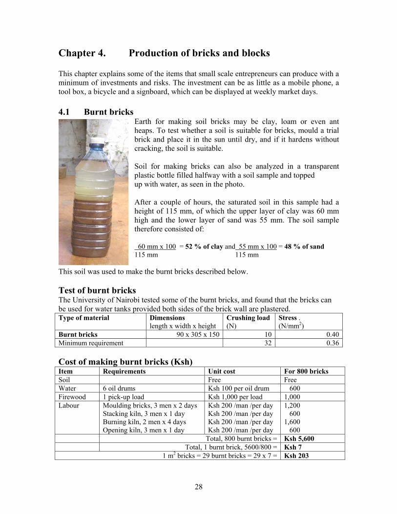
Earth for making soil bricks may be clay, loam or even ant heaps. To test whether a soil is suitable for bricks, mould a trial brick and place it in the sun until dry, and if it hardens without cracking, the soil is suitable. Soil for making bricks can also be analyzed in a transparent plastic bottle filled halfway with a soil sample and topped up with water, as seen in the photo. After a couple of hours, the saturated soil in this sample had a height of 115 mm, of which the upper layer of clay was 60 mm high and the lower layer of sand was 55 mm. The soil sample therefore consisted of: 60 mm x 100 = 52 % of clay and 55 mm x 100 = 48 % of sand 115 mm 115 mm
This soil was used to make the burnt bricks described below. Test of burnt bricks The University of Nairobi tested some of the burnt bricks, and found that the bricks can be used for water tanks provided both sides of the brick wall are plastered. Type of material Dimensions
length x width x height Crushing load (N)
Stress . (N/mm2)
Burnt bricks 90 x 305 x 150 10 0.40Minimum requirement 32 0.36 Cost of making burnt bricks (Ksh) Item Requirements Unit cost For 800 bricks Soil Free Free Water 6 oil drums Ksh 100 per oil drum 600 Firewood 1 pick-up load Ksh 1,000 per load 1,000 Labour Moulding bricks, 3 men x 2 days
Stacking kiln, 3 men x 1 day Burning kiln, 2 men x 4 days Opening kiln, 3 men x 1 day
Ksh 200 /man /per day Ksh 200 /man /per day Ksh 200 /man /per day Ksh 200 /man /per day
1,200 600 1,600 600
Total, 800 burnt bricks = Ksh 5,600 Total, 1 burnt brick, 5600/800 = Ksh 7
1 m2 bricks = 29 burnt bricks = 29 x 7 = Ksh 203
29
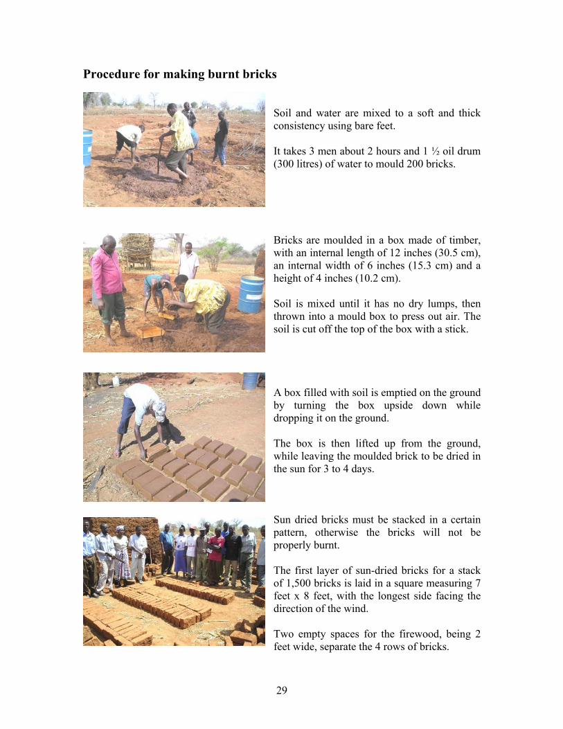
Procedure for making burnt bricks Soil and water are mixed to a soft and thick consistency using bare feet. It takes 3 men about 2 hours and 1 ½ oil drum (300 litres) of water to mould 200 bricks.
Bricks are moulded in a box made of timber, with an internal length of 12 inches (30.5 cm), an internal width of 6 inches (15.3 cm) and a height of 4 inches (10.2 cm). Soil is mixed until it has no dry lumps, then thrown into a mould box to press out air. The soil is cut off the top of the box with a stick. A box filled with soil is emptied on the ground by turning the box upside down while dropping it on the ground. The box is then lifted up from the ground, while leaving the moulded brick to be dried in the sun for 3 to 4 days. Sun dried bricks must be stacked in a certain pattern, otherwise the bricks will not be properly burnt. The first layer of sun-dried bricks for a stack of 1,500 bricks is laid in a square measuring 7 feet x 8 feet, with the longest side facing the direction of the wind. Two empty spaces for the firewood, being 2 feet wide, separate the 4 rows of bricks.
30
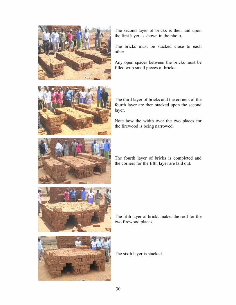
The second layer of bricks is then laid upon the first layer as shown in the photo. The bricks must be stacked close to each other. Any open spaces between the bricks must be filled with small pieces of bricks. The third layer of bricks and the corners of the fourth layer are then stacked upon the second layer. Note how the width over the two places for the firewood is being narrowed. The fourth layer of bricks is completed and the corners for the fifth layer are laid out. The fifth layer of bricks makes the roof for the two firewood places. The sixth layer is stacked.
31
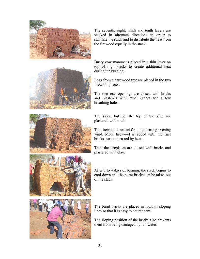
The seventh, eight, ninth and tenth layers are stacked in alternate directions in order to stabilize the stack and to distribute the heat from the firewood equally in the stack. Dusty cow manure is placed in a thin layer on top of high stacks to create additional heat during the burning. Logs from a hardwood tree are placed in the two firewood places. The two rear openings are closed with bricks and plastered with mud, except for a few breathing holes.
The sides, but not the top of the kiln, are plastered with mud. The firewood is sat on fire in the strong evening wind. More firewood is added until the first bricks start to turn red by heat. Then the fireplaces are closed with bricks and plastered with clay. After 3 to 4 days of burning, the stack begins to cool down and the burnt bricks can be taken out of the stack. The burnt bricks are placed in rows of sloping lines so that it is easy to count them. The sloping position of the bricks also prevents them from being damaged by rainwater.
32
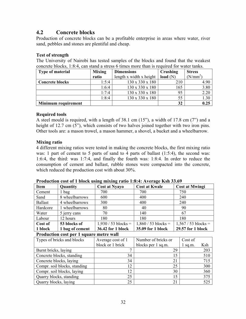
4.2 Concrete blocks Production of concrete blocks can be a profitable enterprise in areas where water, river sand, pebbles and stones are plentiful and cheap. Test of strength The University of Nairobi has tested samples of the blocks and found that the weakest concrete blocks, 1:8:4, can stand a stress 6 times more than is required for water tanks. Type of material Mixing
ratio Dimensions length x width x height
Crushing load (N)
Stress (N/mm2)
Concrete blocks 1:5:4 130 x 330 x 180 210 4.90 1:6:4 130 x 330 x 180 165 3.80 1:7:4 130 x 330 x 180 95 2.20 1:8:4 130 x 330 x 180 55 1.30Minimum requirement 32 0.25
Required tools A steel mould is required, with a length of 38.1 cm (15”), a width of 17.8 cm (7”) and a height of 12.7 cm (5”), which consists of two halves joined together with two iron pins. Other tools are: a mason trowel, a mason hammer, a shovel, a bucket and a wheelbarrow. Mixing ratio 4 different mixing ratios were tested in making the concrete blocks, the first mixing ratio was: 1 part of cement to 5 parts of sand to 4 parts of ballast (1:5:4), the second was: 1:6:4, the third: was 1:7:4, and finally the fourth was: 1:8:4. In order to reduce the consumption of cement and ballast, rubble stones were compacted into the concrete, which reduced the production cost with about 30%. Production cost of 1 block using mixing ratio 1:8:4: Average Ksh 33.69 Item Quantity Cost at Nyayo Cost at Kwale Cost at Mwingi Cement 1 bag 700 700 750 Sand 8 wheelbarrows 600 400 240 Ballast 4 wheelbarrows 300 400 240 Hardcore 1 wheelbarrows 80 40 90 Water 5 jerry cans 70 140 67 Labour 12 hours 180 180 180 Cost of 1 block
53 blocks of 1 bag of cement
1,930 / 53 blocks = 36.42 for 1 block
1,860 / 53 blocks = 35.09 for 1 block
1,567 / 53 blocks = 29.57 for 1 block
Production cost per 1 square metre wall Types of bricks and blocks Average cost of 1
block or 1 brick Number of bricks or blocks per 1 sq.m.
Cost of 1 sq.m. Ksh
Burnt bricks, laying 7 29 203Concrete blocks, standing 34 15 510Concrete blocks, laying 34 21 715Compr. soil blocks, standing 12 25 300Compr. soil blocks, laying 12 30 360Quarry blocks, standing 25 15 375Quarry blocks, laying 25 21 525

33
Procedure for making concrete blocks The mixing ratio of sand, ballast and cement is measured in a wheelbarrow, where the level of 1 bag of cement is marked on the inner side of the wheelbarrow. The volume of sand is measured by filling the sand up to that mark in the wheelbarrow. If the mixing ratio is 1:8, then 8 wheelbarrows of sand is required for every 1 bag of cement. Manual mixing of concrete should always be made as follows:
1) Off load the required 8 wheelbarrows of sand in a heap.
2) Empty the single required bag of
cement on top of the heap.
3) Shovel the first heap into a second heap without water as shown in the photo.
4) Shovel the second heap back into a
third heap without water.
5) Shovel the third heap into a fourth heap without water and flatten the heap.
6) Off load the required 4 wheelbarrows
of ballast onto the flattened heap of mixed sand and cement.
7) Now add a little water at one edge of
the heap of ballast, sand and cement.
8) Then mix the ballast and water with the mixed sand and cement until it has a uniform consistency.
9) Use the mixed concrete in less than 1
hour, otherwise the strength of the concrete will be greatly reduced.
34
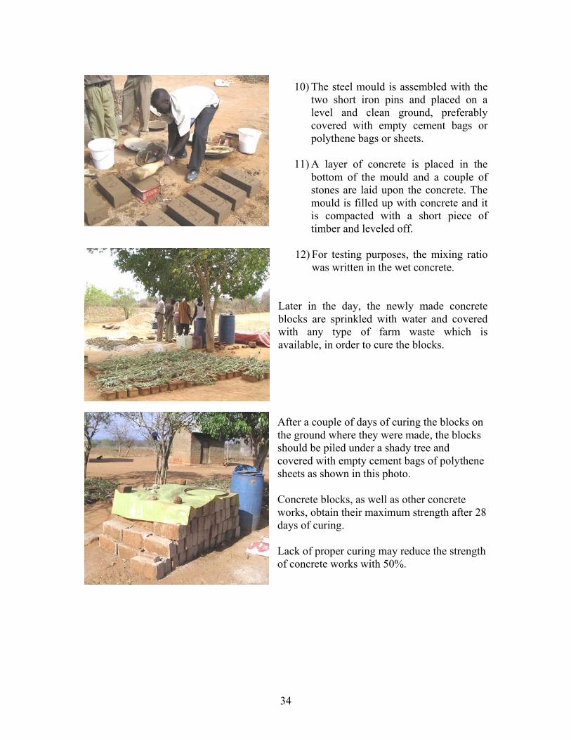
10) The steel mould is assembled with the
two short iron pins and placed on a level and clean ground, preferably covered with empty cement bags or polythene bags or sheets.
11) A layer of concrete is placed in the
bottom of the mould and a couple of stones are laid upon the concrete. The mould is filled up with concrete and it is compacted with a short piece of timber and leveled off.
12) For testing purposes, the mixing ratio
was written in the wet concrete. Later in the day, the newly made concrete blocks are sprinkled with water and covered with any type of farm waste which is available, in order to cure the blocks. After a couple of days of curing the blocks on the ground where they were made, the blocks should be piled under a shady tree and covered with empty cement bags of polythene sheets as shown in this photo. Concrete blocks, as well as other concrete works, obtain their maximum strength after 28 days of curing. Lack of proper curing may reduce the strength of concrete works with 50%.
35
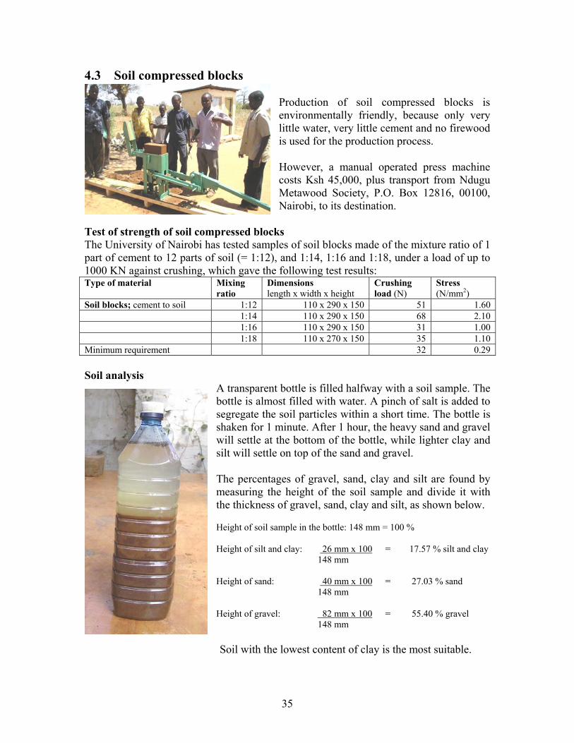
4.3 Soil compressed blocks Production of soil compressed blocks is environmentally friendly, because only very little water, very little cement and no firewood is used for the production process. However, a manual operated press machine costs Ksh 45,000, plus transport from Ndugu Metawood Society, P.O. Box 12816, 00100, Nairobi, to its destination.
Test of strength of soil compressed blocks The University of Nairobi has tested samples of soil blocks made of the mixture ratio of 1 part of cement to 12 parts of soil (= 1:12), and 1:14, 1:16 and 1:18, under a load of up to 1000 KN against crushing, which gave the following test results: Type of material Mixing
ratioDimensions length x width x height
Crushing load (N)
Stress (N/mm2)
Soil blocks; cement to soil 1:12 110 x 290 x 150 51 1.60 1:14 110 x 290 x 150 68 2.10 1:16 110 x 290 x 150 31 1.00 1:18 110 x 270 x 150 35 1.10 Minimum requirement 32 0.29 Soil analysis
A transparent bottle is filled halfway with a soil sample. The bottle is almost filled with water. A pinch of salt is added to segregate the soil particles within a short time. The bottle is shaken for 1 minute. After 1 hour, the heavy sand and gravel will settle at the bottom of the bottle, while lighter clay and silt will settle on top of the sand and gravel. The percentages of gravel, sand, clay and silt are found by measuring the height of the soil sample and divide it with the thickness of gravel, sand, clay and silt, as shown below. Height of soil sample in the bottle: 148 mm = 100 % Height of silt and clay: 26 mm x 100 = 17.57 % silt and clay 148 mm Height of sand: 40 mm x 100 = 27.03 % sand 148 mm Height of gravel: 82 mm x 100 = 55.40 % gravel 148 mm Soil with the lowest content of clay is the most suitable.
36
Ratio of cement to soil The ratio of cement to soil depends on the shrinkage of the soil, and the number of blocks that can be produced from 1 bag of cement depends on the mixing ratio. Shrinkage test
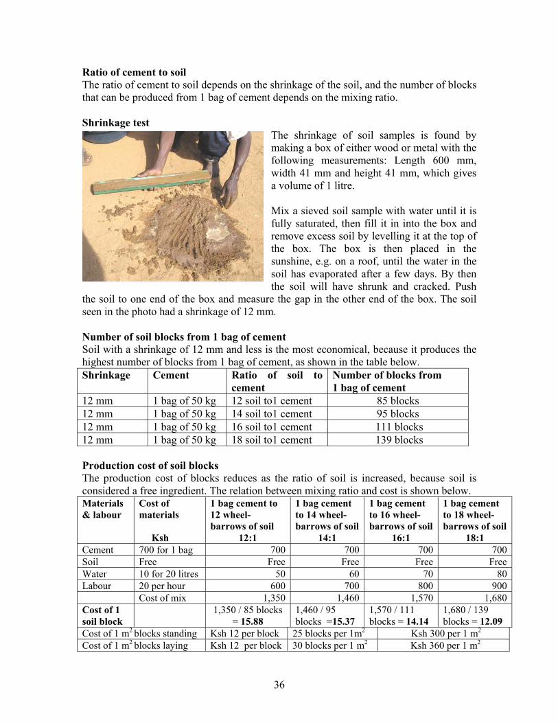
The shrinkage of soil samples is found by making a box of either wood or metal with the following measurements: Length 600 mm, width 41 mm and height 41 mm, which gives a volume of 1 litre. Mix a sieved soil sample with water until it is fully saturated, then fill it in into the box and remove excess soil by levelling it at the top of the box. The box is then placed in the sunshine, e.g. on a roof, until the water in the soil has evaporated after a few days. By then the soil will have shrunk and cracked. Push
the soil to one end of the box and measure the gap in the other end of the box. The soil seen in the photo had a shrinkage of 12 mm. Number of soil blocks from 1 bag of cement Soil with a shrinkage of 12 mm and less is the most economical, because it produces the highest number of blocks from 1 bag of cement, as shown in the table below. Shrinkage Cement Ratio of soil to
cement Number of blocks from 1 bag of cement
12 mm 1 bag of 50 kg 12 soil to1 cement 85 blocks 12 mm 1 bag of 50 kg 14 soil to1 cement 95 blocks 12 mm 1 bag of 50 kg 16 soil to1 cement 111 blocks 12 mm 1 bag of 50 kg 18 soil to1 cement 139 blocks Production cost of soil blocks The production cost of blocks reduces as the ratio of soil is increased, because soil is considered a free ingredient. The relation between mixing ratio and cost is shown below. Materials & labour
Cost of materials Ksh
1 bag cement to 12 wheel- barrows of soil
12:1
1 bag cement to 14 wheel- barrows of soil
14:1
1 bag cement to 16 wheel- barrows of soil
16:1
1 bag cement to 18 wheel- barrows of soil
18:1 Cement 700 for 1 bag 700 700 700 700Soil Free Free Free Free FreeWater 10 for 20 litres 50 60 70 80Labour 20 per hour 600 700 800 900 Cost of mix 1,350 1,460 1,570 1,680 Cost of 1 soil block
1,350 / 85 blocks = 15.88
1,460 / 95 blocks =15.37
1,570 / 111 blocks = 14.14
1,680 / 139 blocks = 12.09
Cost of 1 m2 blocks standing Ksh 12 per block 25 blocks per 1m2 Ksh 300 per 1 m2
Cost of 1 m2 blocks laying Ksh 12 per block 30 blocks per 1 m2 Ksh 360 per 1 m2
37
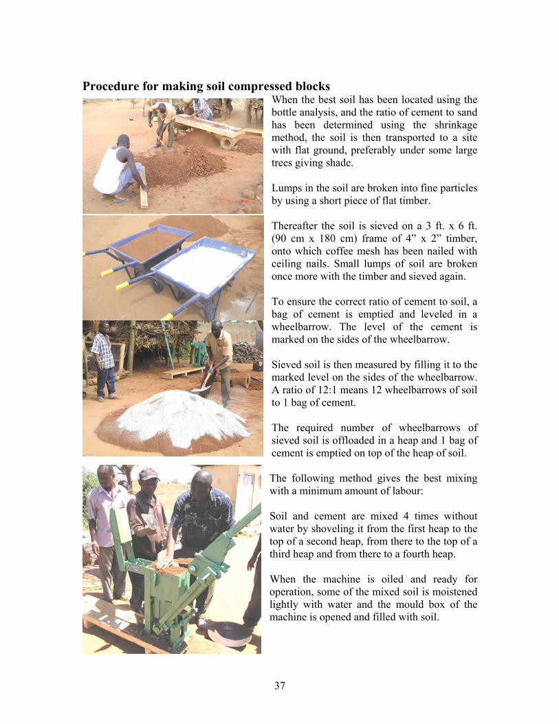
Procedure for making soil compressed blocks
When the best soil has been located using the bottle analysis, and the ratio of cement to sand has been determined using the shrinkage method, the soil is then transported to a site with flat ground, preferably under some large trees giving shade. Lumps in the soil are broken into fine particles by using a short piece of flat timber. Thereafter the soil is sieved on a 3 ft. x 6 ft. (90 cm x 180 cm) frame of 4” x 2” timber, onto which coffee mesh has been nailed with ceiling nails. Small lumps of soil are broken once more with the timber and sieved again. To ensure the correct ratio of cement to soil, a bag of cement is emptied and leveled in a wheelbarrow. The level of the cement is marked on the sides of the wheelbarrow. Sieved soil is then measured by filling it to the marked level on the sides of the wheelbarrow. A ratio of 12:1 means 12 wheelbarrows of soil to 1 bag of cement. The required number of wheelbarrows of sieved soil is offloaded in a heap and 1 bag of cement is emptied on top of the heap of soil. The following method gives the best mixing with a minimum amount of labour: Soil and cement are mixed 4 times without water by shoveling it from the first heap to the top of a second heap, from there to the top of a third heap and from there to a fourth heap. When the machine is oiled and ready for operation, some of the mixed soil is moistened lightly with water and the mould box of the machine is opened and filled with soil.

38
Then the lid is closed on the mould box and the handle turned over and pulled down by one person. This action presses the piston, being the bottom of the mould box, up against the lid thereby compressing the soil in the mould box. The correct pressure exerted by the piston is regulated by turning a knob (seen as a short pipe between the legs at the bottom of the machine) either upwards for reducing the pressure or downwards for increasing it. The correct pressure is the weight of a middle-sized person pulling down the handle. The photo shows a big man applying too high a pressure. When the handle has been pulled down, it is raised to vertical position and pulled down on the other side of the machine, while opening the lid on the mould box. This action presses the piston up to the top of the mould box, thereby pushing the compressed block free of the mould box. The block can now be carried to a shady place for curing. Curing is an important part of manufacturing blocks, because they become brittle and weak without proper curing. In the evening of the same day when the blocks are made, a perforated plastic container is used for giving the blocks a light shower of water. Next morning, the block get a second shower and are then covered with any farm waste or paper that can keep the blocks under shade. After a few days the blocks are stacked under a shady tree, as shown on the photo, and covered with e.g. empty cement bags, plastic or old newspapers.

39
Chapter 5. Private water and sanitation projects 5.1 Repairs of water tanks Many old water tanks, and some new ones, leak, due to various reasons such as lack of proper curing, insufficient reinforcement, substandard materials or poor workmanship. Most of such tanks can be repaired successfully and profitably by small scale contractors using the guidelines presented below. Leakage through cracked walls
Due to insufficient reinforcement of tank walls, water will leak through cracks and fissures of the tanks. Such tanks can be repaired by the following procedure:
1) Chisel off all loose parts on the outside of the wall and the outside of the foundation.
2) Wrap sheets of weld mesh, or BRC mesh, tightly
around the tank with 20 cm overlaps.
3) Plaster a 3 cm thick coat of cement mortar 1:3 onto the mesh and smoothen it off.
4) Wrap empty sacks or polythene sheets tightly
around the plaster with sisal twine, while keeping the plaster moist for 3 weeks.
5) Then paint the external side of the tank with a
weather-proof paint, made by mixing 1 part of cement with 10 parts of lime and water.
Weld mesh being plastered Water poured on the plastered with cement mortar 1:3. wall covered with polythene.
40
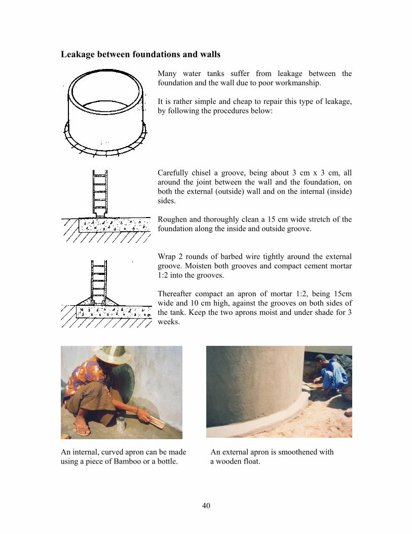
Leakage between foundations and walls Many water tanks suffer from leakage between the foundation and the wall due to poor workmanship. It is rather simple and cheap to repair this type of leakage, by following the procedures below: Carefully chisel a groove, being about 3 cm x 3 cm, all around the joint between the wall and the foundation, on both the external (outside) wall and on the internal (inside) sides. Roughen and thoroughly clean a 15 cm wide stretch of the foundation along the inside and outside groove. Wrap 2 rounds of barbed wire tightly around the external groove. Moisten both grooves and compact cement mortar 1:2 into the grooves. Thereafter compact an apron of mortar 1:2, being 15cm wide and 10 cm high, against the grooves on both sides of the tank. Keep the two aprons moist and under shade for 3 weeks.
An internal, curved apron can be made An external apron is smoothened with using a piece of Bamboo or a bottle. a wooden float.
41
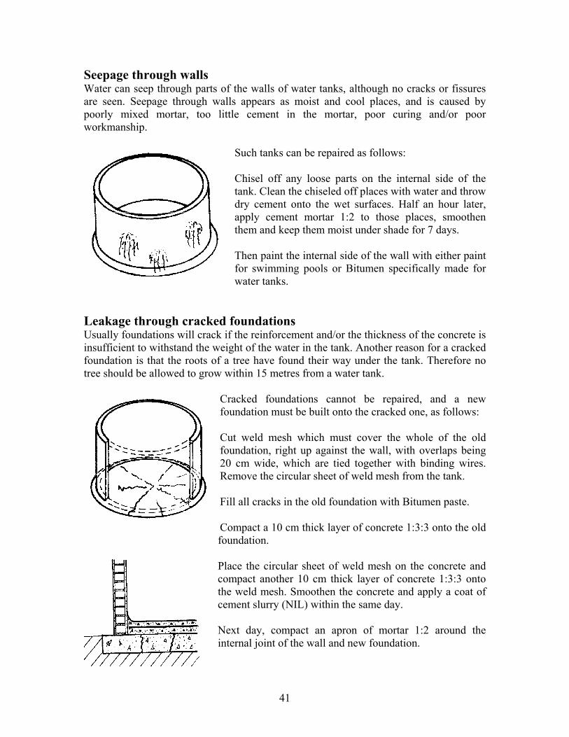
Seepage through walls Water can seep through parts of the walls of water tanks, although no cracks or fissures are seen. Seepage through walls appears as moist and cool places, and is caused by poorly mixed mortar, too little cement in the mortar, poor curing and/or poor workmanship.
Such tanks can be repaired as follows: Chisel off any loose parts on the internal side of the tank. Clean the chiseled off places with water and throw dry cement onto the wet surfaces. Half an hour later, apply cement mortar 1:2 to those places, smoothen them and keep them moist under shade for 7 days. Then paint the internal side of the wall with either paint for swimming pools or Bitumen specifically made for water tanks.
Leakage through cracked foundations Usually foundations will crack if the reinforcement and/or the thickness of the concrete is insufficient to withstand the weight of the water in the tank. Another reason for a cracked foundation is that the roots of a tree have found their way under the tank. Therefore no tree should be allowed to grow within 15 metres from a water tank.
Cracked foundations cannot be repaired, and a new foundation must be built onto the cracked one, as follows: Cut weld mesh which must cover the whole of the old foundation, right up against the wall, with overlaps being 20 cm wide, which are tied together with binding wires. Remove the circular sheet of weld mesh from the tank. Fill all cracks in the old foundation with Bitumen paste. Compact a 10 cm thick layer of concrete 1:3:3 onto the old foundation. Place the circular sheet of weld mesh on the concrete and compact another 10 cm thick layer of concrete 1:3:3 onto the weld mesh. Smoothen the concrete and apply a coat of cement slurry (NIL) within the same day. Next day, compact an apron of mortar 1:2 around the internal joint of the wall and new foundation.

42
5.2 Tanks built of bricks and blocks Introduction Almost all kinds of bricks and blocks can be used for construction of water tanks, provided they are reinforced sufficiently, plastered to be water proof and kept moist under shade (cured) for 3 weeks. Bricks made of soil in a hand operated press are cheap and suitable for construction of water tanks. The bricks are friendly to the environment because very little water and no firewood are required for making the bricks. Construction procedures Foundation and centre pipe The circular excavation for a 10 cu.m. tank has a radius of 160 cm, and the tank wall must be situated 90 cm from the wall of the house. The foundation is dug to a depth of 250 cm below the eave of the roof and at least 15 cm into solid soil. The foundation is made of a 13 cm thick, concrete mixture1:3:4, with a layer of weld mesh in the middle. Also a 90 cm draw-off pipe of 18 mm G.I. pipe is put in the concrete. A 200 cm G.I. pipe of 18 mm is concreted exactly in the centre of the upper layer of concrete in the foundation as a guide for the builder. The wall of bricks or blocks Tie a 180 cm long wire to the vertical centre post, bend the other end to get a radius of 145 cm, which gives the exact position of the outer corners of the bricks or bends to be laid for the circular wall of the tank. The thickness of the vertical joints between the bricks or blocks is found by laying them out along the circle given by the radius wire, and spacing them without mortar. Do not cut the bricks/blocks. Column and beam When the wall is built to a height of 200 cm, a 100 mm PVC pipe is cut to a length of 185 cm. The ends of 4 lengths of 18 mm G.I. pipes, 60 cm long, are heated over fire and inserted into the PVC pipe at equal distances. The PVC pipe is then placed around the centre pipe and filled with concrete.

43
Plaster The outside of the tank is plastered with 2 cm of mortar 1:4. The interior wall and floor is plastered with 2 cm of 1:3 mortar, onto which NIL is applied with a square steel trowel for water proofing. Roof and tap stand If a beam is required for a flat roof of reinforced concrete, it is made in formwork of timber being 10 cm wide and 15 cm deep, and 4 lengths of twisted iron rods are laid into it. The formwork for the roof consists of timbers supported by props. A basin, 2 tins and the overflow pipe are placed on the formwork for the roof. The beam and the formwork are then covered with 10 cm of concrete 1:3:4. After 3 weeks of curing, the formwork can be removed and used elsewhere. Design of a 10 cu.m. tank built of burnt bricks
130
50 mm uPVC pipe drain
7001,000
and 100mm on the upper halfg. 12.5 spaced 50mm on the lower half of wall
100mm concrete reinforced with weld mesh200
300
20mm external plaster over of spiral barbed wire
GL
PLAN (mm)
with (1:2:4) concrete mix
concrete footing300x 300x 150
3"4 pipe GI 600mm long
100mm uPVC pipe with (1:2:4) concrete mix
100 x 150 concrete beam
Manhole cover
A A
400
3,200150
150150150150 2,600
600
20100
2,00
0
1501,3001,300
1,700
1,00
0Ø400
200
200
200
GutterInlet
Steel door
SECTION A - A (mm)
20mm internal plaster with Nil
Bricks or block wall
3"4 outlet GI pipe 900mm long
1 1"4 overflow pipe
GL
44
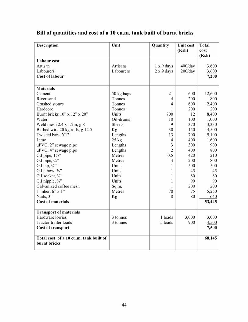
Bill of quantities and cost of a 10 cu.m. tank built of burnt bricks Description Unit Quantity Unit cost
(Ksh) Total cost (Ksh)
Labour cost Artisan Labourers Cost of labour
Artisans Labourers
1 x 9 days 2 x 9 days
400/day 200/day
3,600 3,600 7,200
Materials Cement River sand Crushed stones Hardcore Burnt bricks 10” x 12” x 20” Water Weld mesh 2.4 x 1.2m, g.8 Barbed wire 20 kg rolls, g 12.5 Twisted bars, Y12 Lime uPVC, 2” sewage pipe uPVC, 4” sewage pipe G.I pipe, 1½” G.I pipe, ¾” G.I tap, ¾” G.I elbow, ¾” G.I socket, ¾” G.I nipple, ¾” Galvanized coffee mesh Timber, 6” x 1” Nails, 3” Cost of materials
50 kg bags Tonnes Tonnes Tonnes Units Oil-drums Sheets Kg Lengths 25 kg Lengths Lengths Metres Metres Units Units Units Units Sq.m. Metres Kg
21 4 4 1
700 10 9
30 13 4 3 2
0.5 4 1 1 1 1 1
70 8
600 200 600 200
12 100 370 150 700 400 300 400 420 200 500
45 80 90
200 75 80
12,600
800 2,400
200 8,400
1,000 3,330 4,500 9,100 1,600
900 800
210 800
500 45 80 90
200 5,250
640 53,445
Transport of materials Hardware lorries Tractor trailer loads Cost of transport
3 tonnes 3 tonnes
1 loads
5 loads
3,000
900
3,000 4,500 7,500
Total cost of a 10 cu.m. tank built of burnt bricks
68,145

45
Design of a 15 cu.m. tank built of soil compressed bricks
Steel door
200
100mm uPVC pipe
100x 150 concrete beam
with concrete
50mm for 1m at bottom and 100mm spacing for the remaining height
Barbed wire wrapped around at
20 mm (1:4) external plaster
Ø400
GL
3,510
GL
20 mm floor screed (1:3)
Rounded corner
20 mm (1:3) internal plaster with Nil
1,05
01,
050
1,05
0
290
200
200
400 500 200 200 200
520
100
500
140 3,15020
20
2510
01,
940
100
25
3"4 pipe GI 600mm
Man hole 400 mm Dia.
1 14" overflow pipe
100mm soil ompressed block wall3"4 outlet GI pipe 900mm long
Weld mesh (GB)
DETAIL X (mm)
PLAN (mm)
SECTION A - A (mm)
X
140
400 502 200 200 200
AA
GL
300 x 300 x 150 mass concrete footing
150
1,00
015
0
long as a ladder
Inlet Gutter
400
If you are viewing these drawings on a computer, you may enlarge them by clicking on them and drawing out the arrows in the corner of the frame.

46
Bill of quantities and cost of a 15 cu.m. tank of soil compressed blocks Description Unit Quantity Unit cost
(Ksh) Total cost (Ksh)
Labour cost Artisan Labourers Cost of labour
Artisans Labourers
2 x 10 days 4 x 10days
400/day 200/day
8,000 8,000
16,000
Materials Cement Lime River sand Crushed stones Hardcore, 4” x 6” Soil compressed blocks, 4” x 5” x 12” Water Weld mesh, 8’ x 4’ (feet) No 8 Barbed wire, g12.5, 20 kg Twisted bars, Y12 Binding wire g.8 uPVC, 4” sewage pipe G.I pipe, ¾” G.I tap, elbow, socket, nipple ¾” Galvanized coffee mesh Mosquito mesh Timber, 6” x 1” Pole Nail 3” Cost of materials
50 kg bags 25 kg bag Tonnes Tonnes Tonnes Units Oil-drums Sheets Rolls Metres Kg Metres Metres Tap unit Sq.m. Sq.m. Metres Lengths Kg
25 4 6 4 1
555 10 10 2
15 1 3 3 1 1
0.5 90 8 4
600 400 200 600 200
15 100 370
3,000 18
150 133⅓
200 700 200 100
75 40 80
15,000
1,600 1,200 2,400
200 8,250 1,000 3,700 6,000
270 150 400
600 700
200 50
6,750 320
320 49,110
Transport of materials Hardware lorries Tractor trailer loads Cost of transport
7 tonnes 3 tonnes
1 loads 8 loads
5,000
900
5,000 7,200
12,200
Total cost of a 15 cu.m. tank built of soil compressed blocks
77,310

47
5.3 Repair and installation of gutters Types of gutters Gutters for harvesting rainwater from roofs can be made of several types of materials, such as galvanized iron (G.I.) sheets, timbers, bamboo, cement-coated sacks, etc.
Semi-circular gutter made of G.I. sheets. Square gutter made of G.I. sheets.
Square gutter made of timber. Gutter made of split bamboo. Gradient of gutters
The gutter should have a sloping gradient of 1:100 towards the water tank. The gradient is measured by a transparent hosepipe tied to both ends of a roof, say 20 m long. Water is filled into the pipe until the water level reaches the roofing sheet at Point A. The required gradient, i.e. a drop of 20 cm over the length of 2,000 cm (1:100), is achieved at a point which is 20 cm below the horizontal water level at Point B.
48
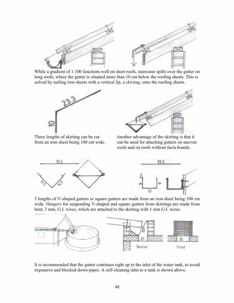
While a gradient of 1:100 functions well on short roofs, rainwater spills over the gutter on long roofs, where the gutter is situated more than 10 cm below the roofing sheets. This is solved by nailing iron sheets with a vertical lip, a skirting, onto the roofing sheets.
Three lengths of skirting can be cut Another advantage of the skirting is that it from an iron sheet being 100 cm wide. can be used for attaching gutters on uneven roofs and on roofs without facia boards.
3 lengths of V-shaped gutters or square gutters are made from an iron sheet being 100 cm wide. Hangers for suspending V-shaped and square gutters from skirtings are made from bent, 3 mm, G.I. wires, which are attached to the skirting with 1 mm G.I. wires.
It is recommended that the gutter continues right up to the inlet of the water tank, to avoid expensive and blocked down-pipes. A self-cleaning inlet to a tank is shown above.

49
5.4 Rope and washer pump Hand pumps are expensive to procure and repair for communities and individuals. It is therefore preferable to use simple but functioning water pumps instead of expensive and non-functioning hand pumps. The ACK Eldoret Region, P.O. Box 6495, Eldoret, [email protected] has been offering training and sale of Rope and Washer Pumps for many years. RELMA of Sida has also been promoting this type of water lifts. It is thought that the production and servicing of these pumps could be a good private enterprise for some contractors.
The rope and washer pump can lift water from the well and up to ground level and surface reservoirs, such as ponds, dams and rivers, and up to elevated water tanks as shown above and in the photos on the next page. According to ACK, their rope and washer pumps have the following pumping capacity: Depth in feet Depth in metres Litres per minute Minutes to fill an oil drum
15 5 85 3 24 8 42 5 36 12 27 8 51 17 19 11 63 21 15 14 75 25 13 16 100 33 10 21 127 42 9 25

50
A demonstration pump at ACK in Eldoret. Turning the wheel made of an old car tyre causes the rope and washers to move up through the ¾” Class C riser pipe, thereby lifting the water up to the outlet pipe. The nylon rope, with rubber washers made of an old car tyre and spaced at intervals, goes around the wheel and the pulley situated in a concrete block at the bottom. A wheel from a bicycle is welded onto the axle, with the wheel functioning as a non-return mechanism and a bearing. A rope and washer pump on a hand dug well for a community at Kusa near Lake Victoria. Another rope and washer pump being used to lift road run-off water from a ground tank, for irrigation of vegetables in Mwala near Machakos. A long almost horizontal riser pipe delivers water from a pond to an elevated tank, for irrigation purposes at an organic farm near Thika.

51
5.5 Latrines Latrine slabs should ideally be made near a riverbed with easy acces to sand and water. The production site should also be situated at a public road, where many people can see the latrine slabs and latrines displayed for sale. This square slab has 4 handles of iron rods to lift and transport the slab, used in a popular low-cost latrine called the AborLoo, where the slab is placed over a pit, 80 cm x 80 cm wide and only 100 cm deep. When the pit is almost filled up, another pit is dug nearby and the slab is transferred to cover the new pit, while the old pit is covered with soil. The 4 handles are also used for anchoring walls made of light materials, such as bamboo or papyrus mats, or gunny sacks coated with cement slurry, onto the slab. To avoid flies and bad smell, the squat hole should either be covered with a lid, or a few handfuls of soil mixed with ashes should be thrown in after each use of the latrine. The construction cost of building a latrine can be limited to the slab only, if the door is made of two short walls and the roof is made of mats, plastic or gunny bags. Latrine slabs may also be circular, with a hole for a ventilation pipe.
In any case, latrine slabs must always be reinforced with a layer of chicken mesh, weld mesh, wire mesh or a mesh of wires spaced 10 cm apart. The concrete mixture should be 1 part cement to 3 parts of river sand and 3 parts of crushed stones (1:3:3), which is kept moist under shade for 3 weeks.
52
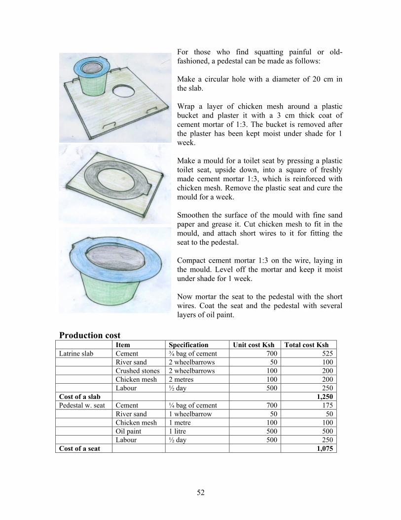
For those who find squatting painful or old-fashioned, a pedestal can be made as follows: Make a circular hole with a diameter of 20 cm in the slab. Wrap a layer of chicken mesh around a plastic bucket and plaster it with a 3 cm thick coat of cement mortar of 1:3. The bucket is removed after the plaster has been kept moist under shade for 1 week. Make a mould for a toilet seat by pressing a plastic toilet seat, upside down, into a square of freshly made cement mortar 1:3, which is reinforced with chicken mesh. Remove the plastic seat and cure the mould for a week. Smoothen the surface of the mould with fine sand paper and grease it. Cut chicken mesh to fit in the mould, and attach short wires to it for fitting the seat to the pedestal. Compact cement mortar 1:3 on the wire, laying in the mould. Level off the mortar and keep it moist under shade for 1 week. Now mortar the seat to the pedestal with the short wires. Coat the seat and the pedestal with several layers of oil paint.
Production cost Item Specification Unit cost Ksh Total cost Ksh Latrine slab Cement ¾ bag of cement 700 525 River sand 2 wheelbarrows 50 100 Crushed stones 2 wheelbarrows 100 200 Chicken mesh 2 metres 100 200 Labour ½ day 500 250Cost of a slab 1,250Pedestal w. seat Cement ¼ bag of cement 700 175 River sand 1 wheelbarrow 50 50 Chicken mesh 1 metre 100 100 Oil paint 1 litre 500 500 Labour ½ day 500 250Cost of a seat 1,075

53
Chapter 6. Community water projects The three types of structures recommended in this chapter require permits from the Ministry of Water and Irrigation before the construction work can be allowed to start, as explained in Chapter 3. It should also be noted that more detailed survey, design and building instructions are presented in the following hand books of this series, namely Water from Dry Riverbeds, Water from Small Earth Dams and Water from Roads. Should these publications be out of stock, they can be downloaded for free from our website www.waterforaridland.com 6.1 Hand dug wells Water-indicating vegetation The most obvious method to identify places with shallow ground water reachable by hand dug wells is to know certain species of trees, whose roots must reach down into the water table to survive droughts. This traditional information is compiled below. Botanical name Kiswahili / Kikamba
names English name Depth to
water-level Cyperus rotundus Kiindiu Tall grass 3 m to 7 m Vangueria tomentosa Muiru / Kikomoa 5 m to 10 m Delonix elata Mwangi 5 m to 10 m Markhamia hildebranditi Muu / Chyoo 8 m to 15 m Hyphaene thebacia Kikoko / Ilala Doum Palm 9 m to 15 m Borassus flabellierfer Mvumo / Kyatha Palm w. bulge 9 m to 15 m Ficus walkefieldii Mombu Wild fig 9 m to 15 m Ficus natalensis Mugumo / Muumo Wild fig 9 m to 15 m Ficus sycamore Mkuyu / Mukuyu Wild fig 9 m to 15 m Kigelia aethiopica Mvunga-vunga / Muatini German sausage 9 m to 20 m Piptadenia hildebranditi Mgunga / Mukami 9 m to 20 m Mgunga / Munina 9 m to 20 m Dowsing Gifted persons can use dowsing to locate underground water sources, by using a tool made from a 1m long brazing rod, cut in two halves, with each half bent at the end to make a handle.
Hold the dowsing rods loosely, parallel to each other, and point them down-wards so that they can swing freely. The hands must be held steady to allow gravity to pull the rods downwards. When walking slowly over an underground water source, the (parallel) rods will swing inwards. A strong pull indicates much water at a shallow depth, while a small pull indicates either less water, a deep water table, or both possibilities.
54
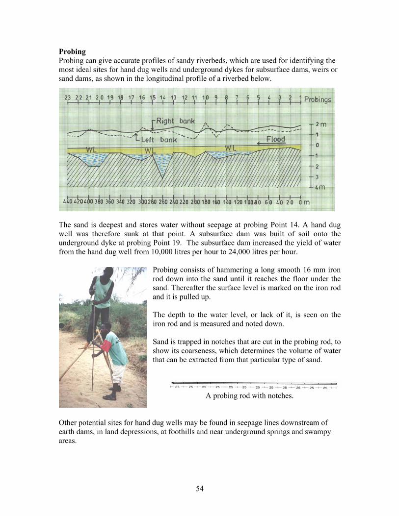
Probing Probing can give accurate profiles of sandy riverbeds, which are used for identifying the most ideal sites for hand dug wells and underground dykes for subsurface dams, weirs or sand dams, as shown in the longitudinal profile of a riverbed below.
The sand is deepest and stores water without seepage at probing Point 14. A hand dug well was therefore sunk at that point. A subsurface dam was built of soil onto the underground dyke at probing Point 19. The subsurface dam increased the yield of water from the hand dug well from 10,000 litres per hour to 24,000 litres per hour.
Probing consists of hammering a long smooth 16 mm iron rod down into the sand until it reaches the floor under the sand. Thereafter the surface level is marked on the iron rod and it is pulled up. The depth to the water level, or lack of it, is seen on the iron rod and is measured and noted down. Sand is trapped in notches that are cut in the probing rod, to show its coarseness, which determines the volume of water that can be extracted from that particular type of sand.
A probing rod with notches.
Other potential sites for hand dug wells may be found in seepage lines downstream of earth dams, in land depressions, at foothills and near underground springs and swampy areas.

55
Sinking hand dug wells The risk of being buried alive in a collapsed excavation can be avoided using a sinking construction technique, where the builder is safe inside the well shaft while excavating it deeper down towards the water table. A circular, shallow groove is cut in the soil by a specially made iron tool, where the well shall be situated. The groove is filled with concrete 1:3:3, and 4 rings of galvanized wires, with 16 short vertical lengths attached, are laid in the concrete.
The iron tool for cutting the circular groove is seen in the above photo. While the foundation ring is cured for a week, curved concrete blocks are made of mortar 1:5. It takes 16 blocks to make a circular course and 112 blocks to build a 1 metre shaft.
Plan of the concrete blocks on the foundation ring. A mould for the concrete blocks
Curved concrete blocks just made in a mould.

56
A sinking well shaft is constructed as follows: 5 rounds of concrete blocks are laid upon the foundation ring in mortar 1:3, with some 10 short lengths of insulated wires in each course of mortar. A G.I wire, which is tied to the short wires in the foundation ring, is placed in each of the 16 holes in the blocks. Cement mortar 1:3 is compacted around the 16 wires, which protrude from the blocks. A circular ring of wire is laid around the 16 wires, and a 12 mm iron rod is tied to two of the vertical wires to function as a step. Another 5 rounds are built onto the first 5 rounds in a similar way, but without insulated wires, and so on until the well shaft is about 1 metre above the ground level. Sand is then back-filled against the well shaft. A builder climbs inside the shaft and removes the soil from the bottom of the shaft. When the shaft has sunk about 1 metre, another 5 courses of blocks are built onto the top of the shaft.
Then the soil is removed again from the bottom of the shaft, it sinks and more blocks are added to the top and so on, until there is about 2 metres of water in the well – in the dry season. Then the insulated wires are pulled out to make infiltration holes in the shaft.
A well shaft being sunk in a riverbank, by contractors under training in Kitui in 2007. The pulley for lifting excavated soil is made of a bicycle wheel. The petrol powered pump for dewatering should have been placed in an excavation outside the well shaft, because as it is now the exhaust fumes may sink down in the well shaft and poison the diggers. The well shaft has built-in steps for climbing down and up. The insulated electrical wires, which shall be pulled out to create infiltration holes, can be seen in the lower part of the shaft.
57
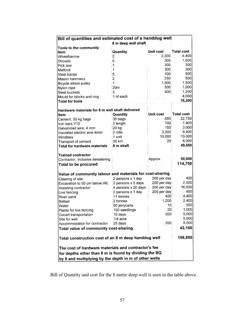
Bill of Quantity and cost for the 8 metre deep well is seen in the table above.
58
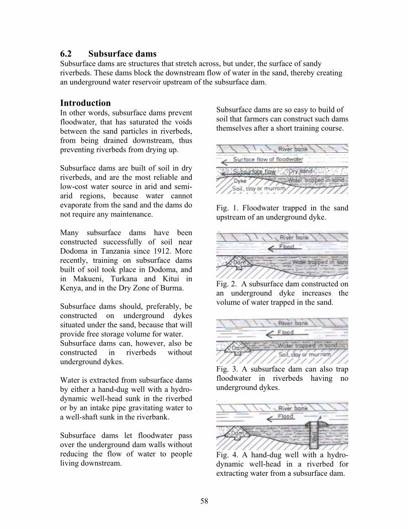
6.2 Subsurface dams Subsurface dams are structures that stretch across, but under, the surface of sandy riverbeds. These dams block the downstream flow of water in the sand, thereby creating an underground water reservoir upstream of the subsurface dam. Introduction In other words, subsurface dams prevent floodwater, that has saturated the voids between the sand particles in riverbeds, from being drained downstream, thus preventing riverbeds from drying up. Subsurface dams are built of soil in dry riverbeds, and are the most reliable and low-cost water source in arid and semi-arid regions, because water cannot evaporate from the sand and the dams do not require any maintenance. Many subsurface dams have been constructed successfully of soil near Dodoma in Tanzania since 1912. More recently, training on subsurface dams built of soil took place in Dodoma, and in Makueni, Turkana and Kitui in Kenya, and in the Dry Zone of Burma. Subsurface dams should, preferably, be constructed on underground dykes situated under the sand, because that will provide free storage volume for water. Subsurface dams can, however, also be constructed in riverbeds without underground dykes. Water is extracted from subsurface dams by either a hand-dug well with a hydro-dynamic well-head sunk in the riverbed or by an intake pipe gravitating water to a well-shaft sunk in the riverbank. Subsurface dams let floodwater pass over the underground dam walls without reducing the flow of water to people living downstream.
Subsurface dams are so easy to build of soil that farmers can construct such dams themselves after a short training course.
Fig. 1. Floodwater trapped in the sand upstream of an underground dyke.
Fig. 2. A subsurface dam constructed on an underground dyke increases the volume of water trapped in the sand.
Fig. 3. A subsurface dam can also trap floodwater in riverbeds having no underground dykes.
Fig. 4. A hand-dug well with a hydro-dynamic well-head in a riverbed for extracting water from a subsurface dam.

59
Site criteria Coarse sand can store more water in its voids than fine-grained sand. The highest yield of water can therefore be drawn from riverbeds with coarse sand.
Fig. 5. Percentage of extractable water. A subsurface dams should not be located where waste from slaughter houses, villages and cattle dips, can contaminate the riverbed. The reservoir of a subsurface dam should not contain salty soil or rocks, because that will make the water salty. Boulders and fractured rocks should not be situated in the reservoirs because they cause leakage. There is always an underground dyke downstream of a waterhole, because it is that dyke that traps the upstream water. Underground dykes are best located a couple of months after flooding by: a) the appearance of dry and low
vegetation on riverbanks, and tall green trees (see Fig.7)
b) confirming by digging trial pits (see
Fig 9), and/or … c) probing with an iron rod hammered
into the sand (see Fig.10), and/or … d) dowsing with two rods made from a
brazing rod (see Fig 11).
Fig. 6. Boulders create leakage.
Fig. 7. Dry vegetation indicates an underground dyke, while tall green trees show where water can be drawn.
Fig. 8. Waterholes provide water due to an underground dyke being downstream.
Fig. 9. Trial pits can be dug in riverbeds to confirm dyke and extraction point.
Fig. 10. Probing rods made of iron bars can also show dyke and extraction point.
Fig. 11. Dowing rods can be used by gifted persons.
60
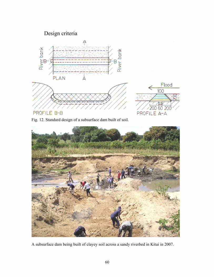
Design criteria
Fig. 12. Standard design of a subsurface dam built of soil.
A subsurface dam being built of clayey soil across a sandy riverbed in Kitui in 2007.
61
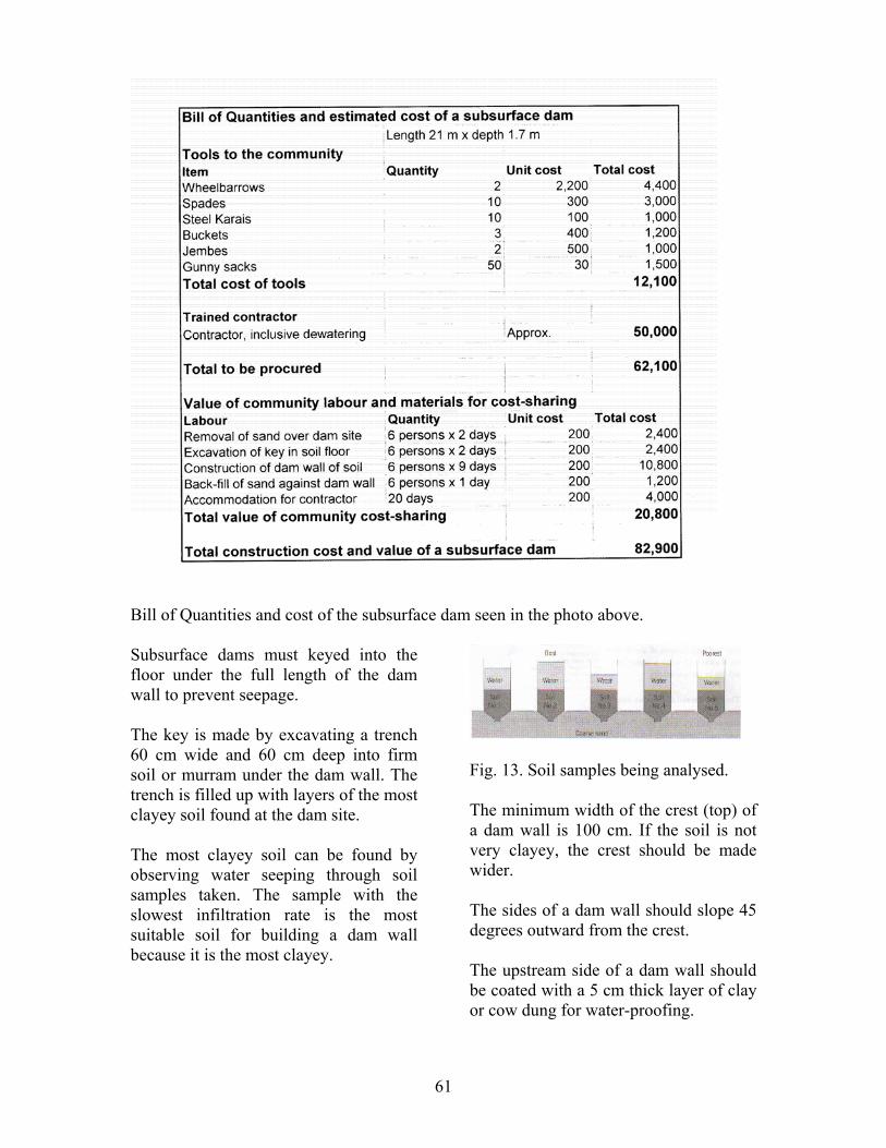
Bill of Quantities and cost of the subsurface dam seen in the photo above. Subsurface dams must keyed into the floor under the full length of the dam wall to prevent seepage. The key is made by excavating a trench 60 cm wide and 60 cm deep into firm soil or murram under the dam wall. The trench is filled up with layers of the most clayey soil found at the dam site. The most clayey soil can be found by observing water seeping through soil samples taken. The sample with the slowest infiltration rate is the most suitable soil for building a dam wall because it is the most clayey.
Fig. 13. Soil samples being analysed. The minimum width of the crest (top) of a dam wall is 100 cm. If the soil is not very clayey, the crest should be made wider. The sides of a dam wall should slope 45 degrees outward from the crest. The upstream side of a dam wall should be coated with a 5 cm thick layer of clay or cow dung for water-proofing.

62
Construction procedures
1) The sand overlaying an underground dyke is removed in a stretch 2 metres wider than the base of the dam. 2) The width of the base is excavated to a depth of 20 cm into the clay or murram floor of the riverbed. 3) A key, 60 cm wide and 60 cm deep or more, is excavated into firm soil along the middle of the dam wall into the banks at both ends of the dam wall.
4) The dam wall is built of the most clayey soil found on the site. The clayey soil is compacted into the key and dam wall in layers of about 20 cm thickness until it reaches the top of the dam wall. 5) The sides of the dam wall are cut to 45 degrees slope and smoothened. 6) The upstream side of the dam wall is water-proofed by compacting a 5 cm layer of clay, or cow-dung mixed with soil, onto the
dam wall.
63
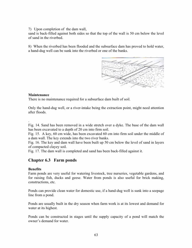
7) Upon completion of the dam wall, sand is back-filled against both sides so that the top of the wall is 50 cm below the level of sand in the riverbed. 8) When the riverbed has been flooded and the subsurface dam has proved to hold water, a hand-dug well can be sunk into the riverbed or one of the banks.
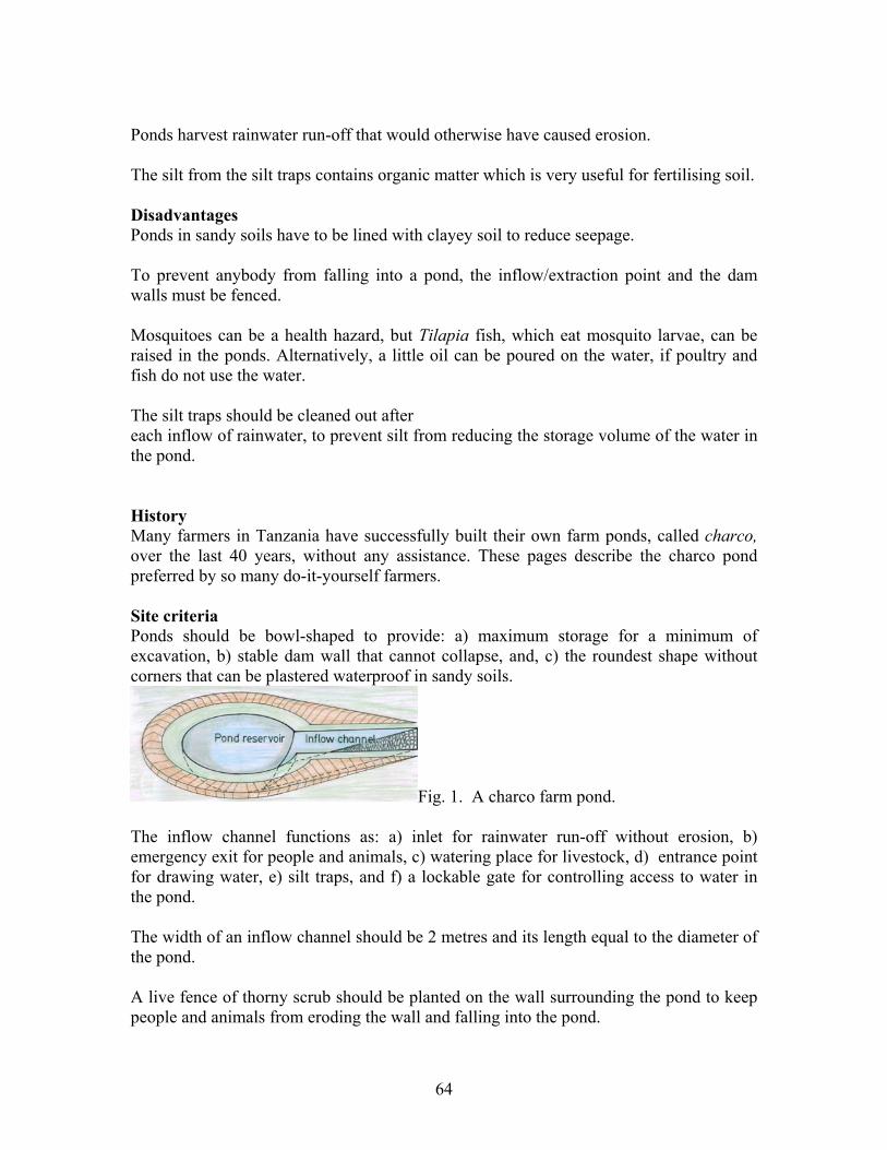
Maintenance There is no maintenance required for a subsurface dam built of soil. Only the hand-dug well, or a river-intake being the extraction point, might need attention after floods. . Fig. 14. Sand has been removed in a wide stretch over a dyke. The base of the dam wall has been excavated to a depth of 20 cm into firm soil. Fig. 15. A key, 60 cm wide, has been excavated 60 cm into firm soil under the middle of a dam wall. The key extends into the two river banks. Fig. 16. The key and dam wall have been built up 50 cm below the level of sand in layers of compacted clayey soil. Fig. 17. The dam wall is completed and sand has been back-filled against it. Chapter 6.3 Farm ponds Benefits Farm ponds are very useful for watering livestock, tree nurseries, vegetable gardens, and for raising fish, ducks and geese. Water from ponds is also useful for brick making, constructions, etc. Ponds can provide clean water for domestic use, if a hand-dug well is sunk into a seepage line from a pond. Ponds are usually built in the dry season when farm work is at its lowest and demand for water at its highest. Ponds can be constructed in stages until the supply capacity of a pond will match the owner’s demand for water.
64
Ponds harvest rainwater run-off that would otherwise have caused erosion. The silt from the silt traps contains organic matter which is very useful for fertilising soil. Disadvantages Ponds in sandy soils have to be lined with clayey soil to reduce seepage. To prevent anybody from falling into a pond, the inflow/extraction point and the dam walls must be fenced. Mosquitoes can be a health hazard, but Tilapia fish, which eat mosquito larvae, can be raised in the ponds. Alternatively, a little oil can be poured on the water, if poultry and fish do not use the water. The silt traps should be cleaned out after each inflow of rainwater, to prevent silt from reducing the storage volume of the water in the pond. History Many farmers in Tanzania have successfully built their own farm ponds, called charco, over the last 40 years, without any assistance. These pages describe the charco pond preferred by so many do-it-yourself farmers. Site criteria Ponds should be bowl-shaped to provide: a) maximum storage for a minimum of excavation, b) stable dam wall that cannot collapse, and, c) the roundest shape without corners that can be plastered waterproof in sandy soils.
Fig. 1. A charco farm pond. The inflow channel functions as: a) inlet for rainwater run-off without erosion, b) emergency exit for people and animals, c) watering place for livestock, d) entrance point for drawing water, e) silt traps, and f) a lockable gate for controlling access to water in the pond. The width of an inflow channel should be 2 metres and its length equal to the diameter of the pond. A live fence of thorny scrub should be planted on the wall surrounding the pond to keep people and animals from eroding the wall and falling into the pond.
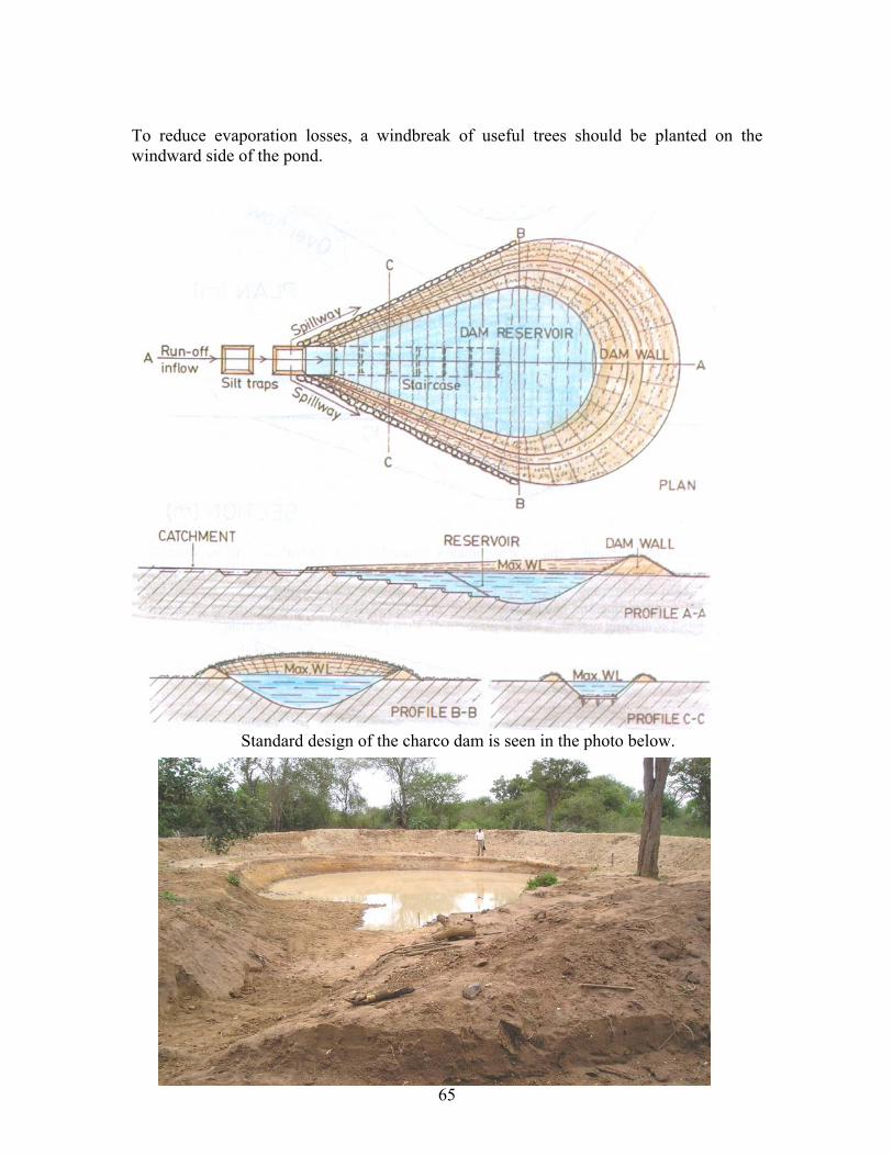
65
To reduce evaporation losses, a windbreak of useful trees should be planted on the windward side of the pond.
Standard design of the charco dam is seen in the photo below.

55
A charco dam under construction at Mutomo, Kitui, during a training course in2007. Location of the pond The pond must always be situated near the lowest part of a catchment (roads, compounds, fields, rocks etc.) to allow rainwater to run into the pond by gravity. The pond should be located conveniently close to where the water will be used.
Fig. 2. Plan of rainwater running off from a compound to a pond.
Fig. 3. Section of a soil bund to divert rainwater run-off to a pond. The slope (gradient) of the bund leading to the pond should be 3 cm per 100 cm. Steeper gradients result in siltation, and lesser gradients reduces inflow of run-off.
Fig. 4. A gradient of 3:100 is measured by placing a spirit level horizontally on a 100 cm length of timber with two legs, one being 3 cm longer than the other leg.
Fig. 5. Analysis of soil samples show which site has the best soil for a pond. Remove cap and bottom from plastic bottles and place them upside down. Fill soil samples into the bottles and top up with water, while watching the seepage. The best soil has the slowest seepage. Selecting the best size of a pond The size of a pond can be determined using the design and tables below.
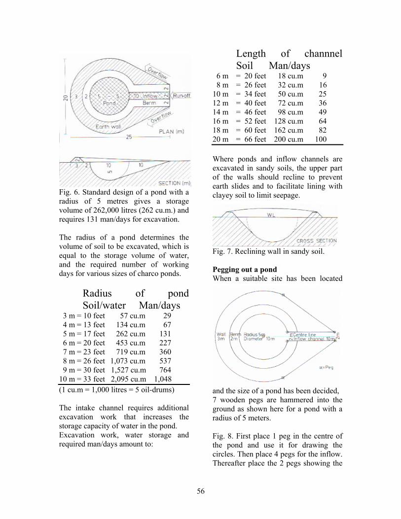
56
Fig. 6. Standard design of a pond with a radius of 5 metres gives a storage volume of 262,000 litres (262 cu.m.) and requires 131 man/days for excavation. The radius of a pond determines the volume of soil to be excavated, which is equal to the storage volume of water, and the required number of working days for various sizes of charco ponds.
Radius of pond Soil/water Man/days
3 m = 10 feet 57 cu.m 29 4 m = 13 feet 134 cu.m 67 5 m = 17 feet 262 cu.m 131 6 m = 20 feet 453 cu.m 227 7 m = 23 feet 719 cu.m 360 8 m = 26 feet 1,073 cu.m 537 9 m = 30 feet 1,527 cu.m 764 10 m = 33 feet 2,095 cu.m 1,048 (1 cu.m = 1,000 litres = 5 oil-drums) The intake channel requires additional excavation work that increases the storage capacity of water in the pond. Excavation work, water storage and required man/days amount to:
Length of channnel Soil Man/days
6 m = 20 feet 18 cu.m 9 8 m = 26 feet 32 cu.m 16 10 m = 34 feet 50 cu.m 25 12 m = 40 feet 72 cu.m 36 14 m = 46 feet 98 cu.m 49 16 m = 52 feet 128 cu.m 64 18 m = 60 feet 162 cu.m 82 20 m = 66 feet 200 cu.m 100 Where ponds and inflow channels are excavated in sandy soils, the upper part of the walls should recline to prevent earth slides and to facilitate lining with clayey soil to limit seepage.
Fig. 7. Reclining wall in sandy soil. Pegging out a pond When a suitable site has been located
and the size of a pond has been decided, 7 wooden pegs are hammered into the ground as shown here for a pond with a radius of 5 meters. Fig. 8. First place 1 peg in the centre of the pond and use it for drawing the circles. Then place 4 pegs for the inflow. Thereafter place the 2 pegs showing the
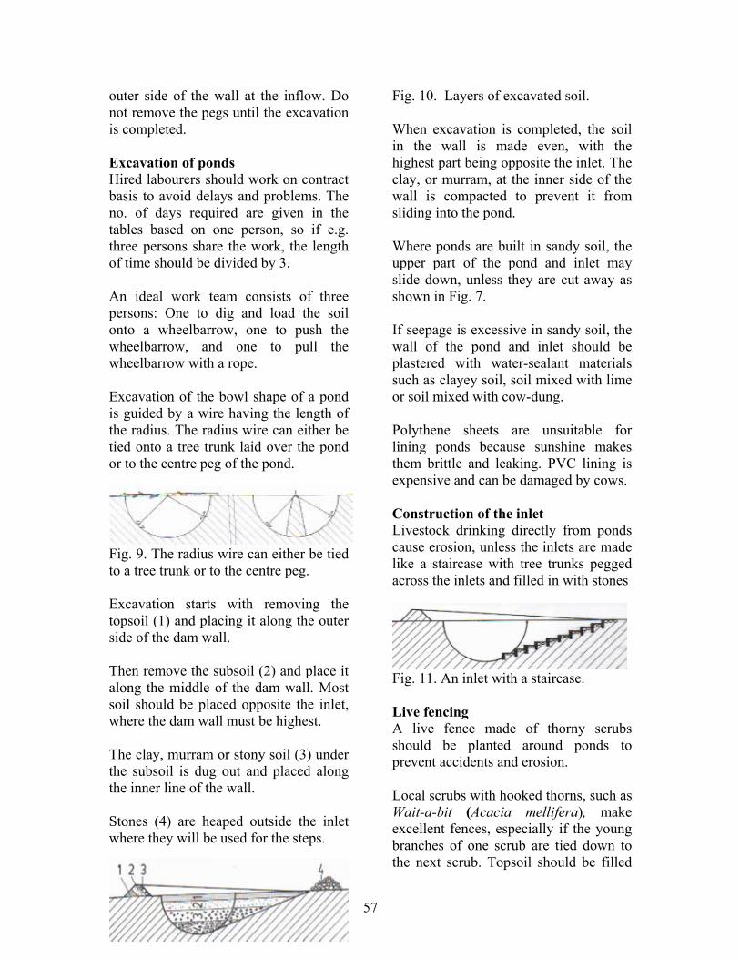
57
outer side of the wall at the inflow. Do not remove the pegs until the excavation is completed. Excavation of ponds Hired labourers should work on contract basis to avoid delays and problems. The no. of days required are given in the tables based on one person, so if e.g. three persons share the work, the length of time should be divided by 3. An ideal work team consists of three persons: One to dig and load the soil onto a wheelbarrow, one to push the wheelbarrow, and one to pull the wheelbarrow with a rope. Excavation of the bowl shape of a pond is guided by a wire having the length of the radius. The radius wire can either be tied onto a tree trunk laid over the pond or to the centre peg of the pond.
Fig. 9. The radius wire can either be tied to a tree trunk or to the centre peg. Excavation starts with removing the topsoil (1) and placing it along the outer side of the dam wall. Then remove the subsoil (2) and place it along the middle of the dam wall. Most soil should be placed opposite the inlet, where the dam wall must be highest. The clay, murram or stony soil (3) under the subsoil is dug out and placed along the inner line of the wall. Stones (4) are heaped outside the inlet where they will be used for the steps.
Fig. 10. Layers of excavated soil. When excavation is completed, the soil in the wall is made even, with the highest part being opposite the inlet. The clay, or murram, at the inner side of the wall is compacted to prevent it from sliding into the pond. Where ponds are built in sandy soil, the upper part of the pond and inlet may slide down, unless they are cut away as shown in Fig. 7. If seepage is excessive in sandy soil, the wall of the pond and inlet should be plastered with water-sealant materials such as clayey soil, soil mixed with lime or soil mixed with cow-dung. Polythene sheets are unsuitable for lining ponds because sunshine makes them brittle and leaking. PVC lining is expensive and can be damaged by cows. Construction of the inlet Livestock drinking directly from ponds cause erosion, unless the inlets are made like a staircase with tree trunks pegged across the inlets and filled in with stones
Fig. 11. An inlet with a staircase. Live fencing A live fence made of thorny scrubs should be planted around ponds to prevent accidents and erosion. Local scrubs with hooked thorns, such as Wait-a-bit (Acacia mellifera), make excellent fences, especially if the young branches of one scrub are tied down to the next scrub. Topsoil should be filled
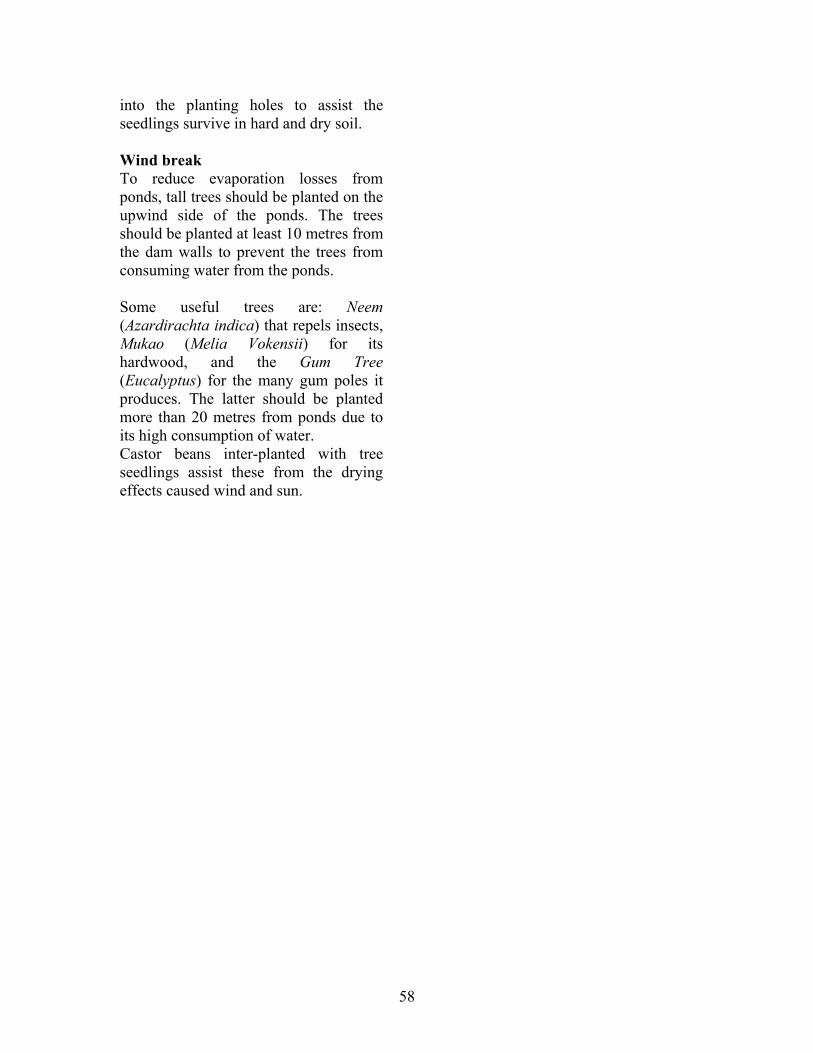
58
into the planting holes to assist the seedlings survive in hard and dry soil. Wind break To reduce evaporation losses from ponds, tall trees should be planted on the upwind side of the ponds. The trees should be planted at least 10 metres from the dam walls to prevent the trees from consuming water from the ponds. Some useful trees are: Neem (Azardirachta indica) that repels insects, Mukao (Melia Vokensii) for its hardwood, and the Gum Tree (Eucalyptus) for the many gum poles it produces. The latter should be planted more than 20 metres from ponds due to its high consumption of water. Castor beans inter-planted with tree seedlings assist these from the drying effects caused wind and sun.
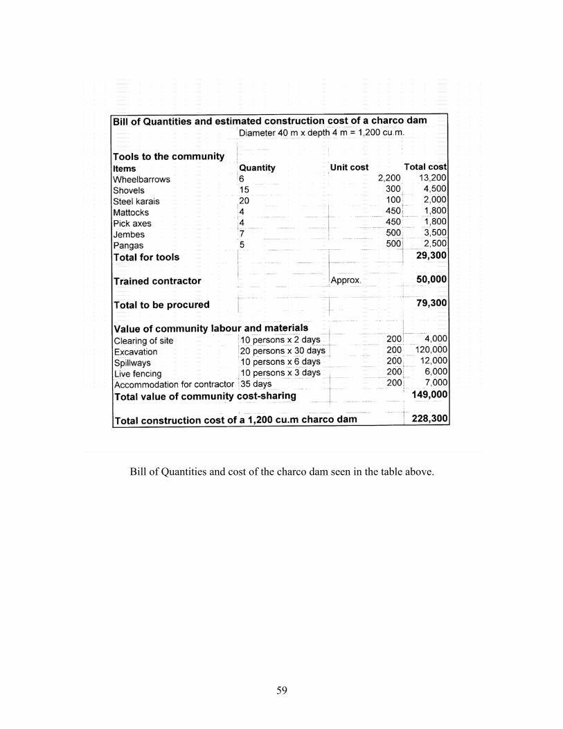
59
Bill of Quantities and cost of the charco dam seen in the table above.
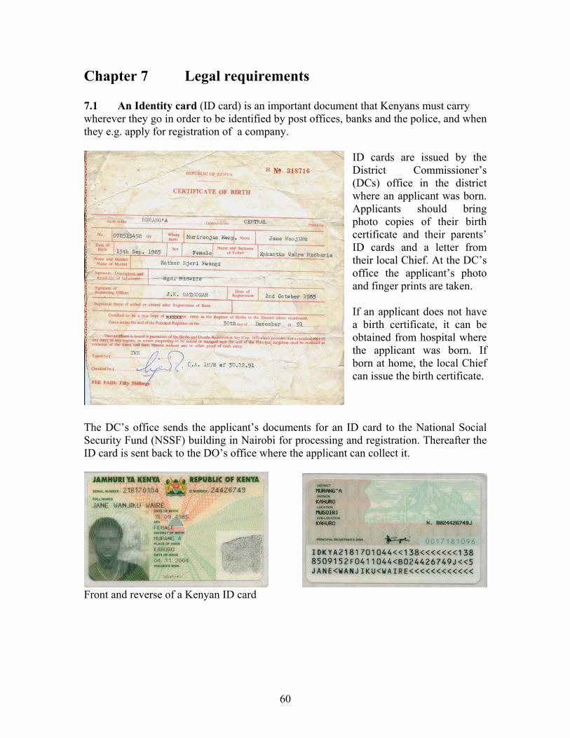
60
Chapter 7 Legal requirements 7.1 An Identity card (ID card) is an important document that Kenyans must carry wherever they go in order to be identified by post offices, banks and the police, and when they e.g. apply for registration of a company.
ID cards are issued by the District Commissioner’s (DCs) office in the district where an applicant was born. Applicants should bring photo copies of their birth certificate and their parents’ ID cards and a letter from their local Chief. At the DC’s office the applicant’s photo and finger prints are taken. If an applicant does not have a birth certificate, it can be obtained from hospital where the applicant was born. If born at home, the local Chief can issue the birth certificate.
The DC’s office sends the applicant’s documents for an ID card to the National Social Security Fund (NSSF) building in Nairobi for processing and registration. Thereafter the ID card is sent back to the DO’s office where the applicant can collect it.
Front and reverse of a Kenyan ID card

61
7.2 A Personal Identification Number (PIN), can be obtained by filling in an application form called T.Q1 at Kenya Revenue Authority’s (KRA) banking hall on the ground floor of Times Tower in Nairobi.
A copy of a T.Q1 form for applying for a personal PIN number is shown on the left. A copy of a personal PIN card, which is used when paying taxes, buying a motor vehicle, a plot or a piece of land as well as many other financial transactions, is seen below.
7.3 A post box address can be rented from a post office. Firms with much correspondence may rent a Private Post Box with a lockable canvas bag but this option is more expensive than a post box. 7.4 A physical address is the name of the house, street, estate and area where the office, workshop, store or residence is located. 7.5 Telephone, fax and email are normally required for a business, although a mobile cell telephone is sufficient, cheaper and much more convenient than landlines for telephone calls, messages, emails, etc. A mobile phone can be connected with a cord to either a desktop or a laptop computer which is connected wireless to an Internet Service Provider (ISP). This arrangement makes it easy, cheap and quick to communicate with anybody being within coverage of the internet worldwide. 7.6 A Single Business Permit is required by the local County Council. According to The Kenya Gazette of 11th January 2002, VOL. C1V – No. 2, Gazette Notice No. 220, the fee varies according to the number of persons employed, the location of the business and the rates fixed by the local County Councils.

62
7.7 A Trade Test Certificate, which certifies three grades of artisans as III, II and I, is an advantage but not necessary for registering a company.
Application forms for trade tests, as seen on the left, can be obtained from The Director, Industrial Training, P.O. Box 74494, 002000, Nairobi, which is at the Ministry of Labour building on Lusaka Road in Nairobi. For a grade III test a photo of the applicant and Ksh 1,300 must be attached to the filled in form and returned to The Director of Industrial Training. The fees for trade tests for grade II and I are higher than for grade III. The Directorate replies to an application by posting an appointment letter that describes the time, date and the place nearest to the applicant’s residence where the test shall take place, as seen on the left.
A Trade Test Certificate for Grade III, of which a photocopy is shown above, is a useful certificate when seeking employment or registration of a company.
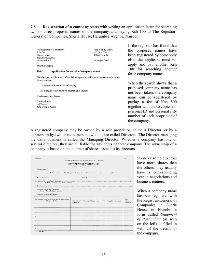
63
7.8 Registration of a company starts with writing an application letter for searching two or three proposed names of the company and paying Ksh 100 to The Registrar-General of Companies, Sheria House, Harambee Avenue, Nairobi.
If the registrar has found that the proposed names have been registered by somebody else, the applicant must re-apply and pay another Ksh 100 for searching another three company names. When the search shows that a proposed company name has not been taken, the company name can be registered by paying a fee of Ksh 800 together with photo copies of personal ID and personal PIN number of each proprietor of the company.
A registered company may be owned by a sole proprietor, called a Director, or by a partnership by two or more persons who all are called Directors. The Director managing the daily business is called the Managing Director. Whether a company has one or several directors, they are all liable for any debts of their company. The ownership of a company is based on the number of shares issued to its directors.
If one or some directors have more shares than the others, they usually have a corresponding vote in negotiations and business matters. When a company name has been registered with the Registrar-General of Companies in Sheria House in Nairobi, a form called Statement of Particulars (as seen on the left) is filled in with all the details of the company.
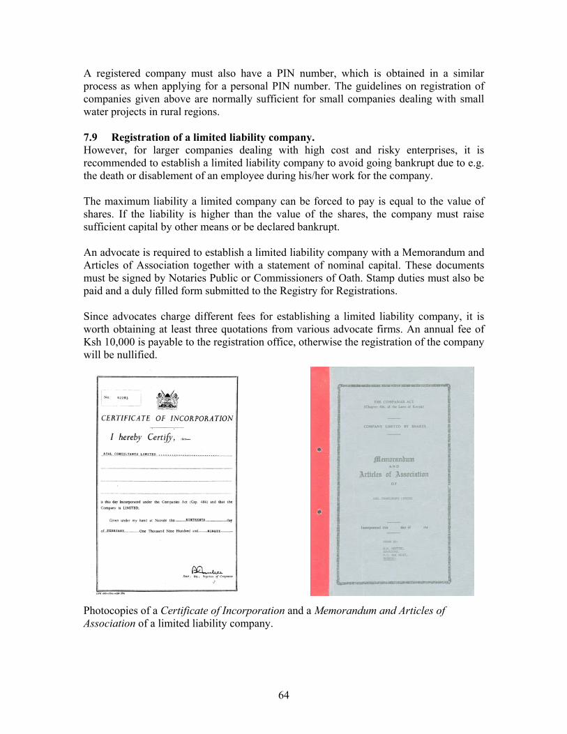
64
A registered company must also have a PIN number, which is obtained in a similar process as when applying for a personal PIN number. The guidelines on registration of companies given above are normally sufficient for small companies dealing with small water projects in rural regions. 7.9 Registration of a limited liability company. However, for larger companies dealing with high cost and risky enterprises, it is recommended to establish a limited liability company to avoid going bankrupt due to e.g. the death or disablement of an employee during his/her work for the company. The maximum liability a limited company can be forced to pay is equal to the value of shares. If the liability is higher than the value of the shares, the company must raise sufficient capital by other means or be declared bankrupt. An advocate is required to establish a limited liability company with a Memorandum and Articles of Association together with a statement of nominal capital. These documents must be signed by Notaries Public or Commissioners of Oath. Stamp duties must also be paid and a duly filled form submitted to the Registry for Registrations. Since advocates charge different fees for establishing a limited liability company, it is worth obtaining at least three quotations from various advocate firms. An annual fee of Ksh 10,000 is payable to the registration office, otherwise the registration of the company will be nullified.
Photocopies of a Certificate of Incorporation and a Memorandum and Articles of Association of a limited liability company.

65
7.10 Current bank accounts with cheque books and monthly bank statements are required for limited companies due to the following reasons:
1) A certified public accountant uses the bank statements to prepare an Annual Return to the Income Tax Department because incomes paid to the company in cheques, cash deposits and transfers are shown on the statements.
2) Payments to suppliers, employees, electricity, water, rents, telephone, etc. paid by
cheques are shown on the bank statements and can be deducted from the taxable income by the certified public accountant.
3) Cheques deposited and withdrawn from a bank account are shown on the
statements and is valid proof of payments even without receipts.
4) Cheques minimize risks of theft and robbery because a stolen or lost cheque can be made invalid by phoning to the bank.
Two sizes of cheque books are available. The small one seen above has 50 leaves, while the larger cheque book has 100 leaves. A leaf of a cheque book still attached to the counterfoil on its left side. For the record, the text written on a cheque is copied on the counterfoil that is attached to the cheque book. The leaf is then pulled off the counterfoil and given as payment. A guide found on the first page of cheque books. Advice is given on the reverse side of the front page of cheque books.
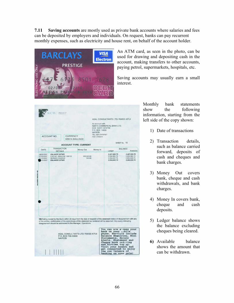
66
7.11 Saving accounts are mostly used as private bank accounts where salaries and fees can be deposited by employers and individuals. On request, banks can pay recurrent monthly expenses, such as electricity and house rent, on behalf of the account holder.
An ATM card, as seen in the photo, can be used for drawing and depositing cash in the account, making transfers to other accounts, paying petrol, supermarkets, hospitals, etc. Saving accounts may usually earn a small interest.
Monthly bank statements show the following information, starting from the left side of the copy shown:
1) Date of transactions
2) Transaction details, such as balance carried forward, deposits of cash and cheques and bank charges.
3) Money Out covers
bank, cheque and cash withdrawals, and bank charges.
4) Money In covers bank,
cheque and cash deposits.
5) Ledger balance shows
the balance excluding cheques being cleared.
6) Available balance
shows the amount that can be withdrawn.

67
7.12 Taxable income. A limited liability company must submit an account for a full financial year, called either an Annual Return or a Financial Statement to the Income Tax Department before the 30th April every year. It is advisable to engage a Certified Public Accountant to work out this account, which is based on bank statements, receipts, depreciation of plants and equipment, losses, income, etc. The Certified Public Accountant will also handle negotiations with the Income Tax Departments for the tax payable for the Annual Return. The Income Tax Department is the department within Kenya Revenue Authority (KRA) that deals with taxation of income generated by individuals and companies.
7.13 Accounts
It is important to glue all receipts onto A4 sheets of paper and file them in a spring folder, because many of the expenditures can be deducted from taxable income.
Each receipt is given with a number, starting with Number 1 on the first receipt on the first page in the spring file.
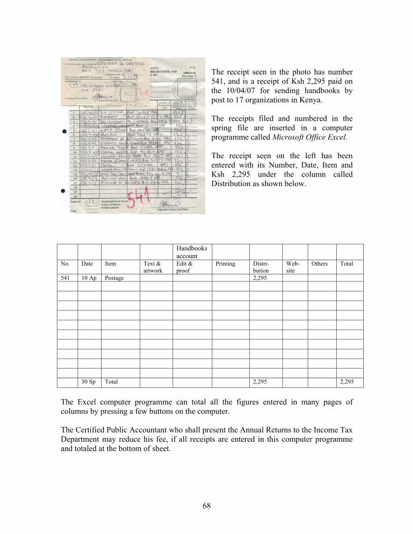
68
The receipt seen in the photo has number 541, and is a receipt of Ksh 2,295 paid on the 10/04/07 for sending handbooks by post to 17 organizations in Kenya. The receipts filed and numbered in the spring file are inserted in a computer programme called Microsoft Office Excel. The receipt seen on the left has been entered with its Number, Date, Item and Ksh 2,295 under the column called Distribution as shown below.
Handbooks
account
No. Date Item Text & artwork
Edit & proof
Printing Distri- bution
Web- site
Others Total
541 10 Ap Postage 2,295 30 Sp Total 2,295 2,295
The Excel computer programme can total all the figures entered in many pages of columns by pressing a few buttons on the computer. The Certified Public Accountant who shall present the Annual Returns to the Income Tax Department may reduce his fee, if all receipts are entered in this computer programme and totaled at the bottom of sheet.

69
References De Vrees, L. 1987. Rainwater Tank Programme. Machakos Diocese, Box 640, Machakos, Kenya. Enyatseng, G. 1998. Evaluation of Ferrocement Water Tanks. Botswana Technology Centre, P/Bag 0082, Gaborone, Botswana. Gould, J. 1987. Assessment of Roof and Ground Catchment Systems in Botswana. 3rd IRSA Conference, Khon Kaen University, Thailand. Gould, J. 1991. Rainwater Catchment Systems for Household Water Supply. ENSIC Review, A.I.T. Bangkok, Thailand. Gould, J. 1995. Development in Rainwater Catchment Systems in Eastern and Southern Africa. 7th IRSA Conference, Beijing, China. Gould, J. 1998. Review of Recent Developments in Rainwater Catchment Systems Technology in Eastern and Southern Africa. Science, Vol. 16, No.1. Gould, J. and Nissen-Petersen, E. 1999. Rainwater Catchment Systems for Domestic Supply. Intermediate Technology Publications, London, UK. Hasse, R. 1989. Rainwater Reservoirs above Ground Structures for Roof Catchments. GATE, Germany. Lee, M. and Nissen-Petersen, E. 1989. The Use of Low-cost Selfhelp Rainwater Harvesting Systems for Community Water Supply in Southern Kenya. 4th IRCA Conference, Manila, Philippines. Lee, M. and Visschers, J.T. 1990. Water Harvesting in Five African Countries. IRC, The Hague, Netherlands. Nissen-Petersen, E. 1982. Rain Catchment and Water Supply in Rural Africa. Hodder & Stoughton, London, UK. Nissen-Petersen, E. 1990. Water Tanks with Guttering and Hand-pump. Manual No. 1 of Harvesting Rainwater in Semi-arid Africa. Danida, Kenya. Nissen-Petersen, E. 1992. How to Build Cylindrical Tanks with Domes. ASALCON. Nissen-Petersen, E. 1992. How to Build An Underground Tank with Dome. ASALCON. Nissen-Petersen, E. 1992. How to Repair Various Types of Water Tanks. ASALCON. Nissen-Petersen, E. 1992. How to Make and Install Gutters with Splash-guard. ASALCON. Nissen-Petersen, K. 1992. How to Build Smaller Water Tanks and Jars. ASALCON. Nissen-Petersen, E. 2006-07. The other 7 handbooks in this current series. Watt, S. 1978. Ferrocement Water Tanks and their Construction. ITDG London, UK.
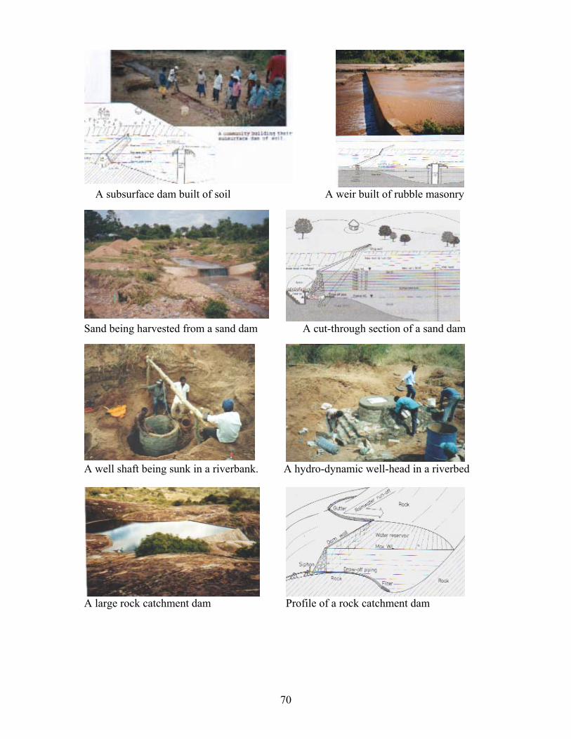
70
A subsurface dam built of soil A weir built of rubble masonry
Sand being harvested from a sand dam A cut-through section of a sand dam
A well shaft being sunk in a riverbank. A hydro-dynamic well-head in a riverbed
A large rock catchment dam Profile of a rock catchment dam
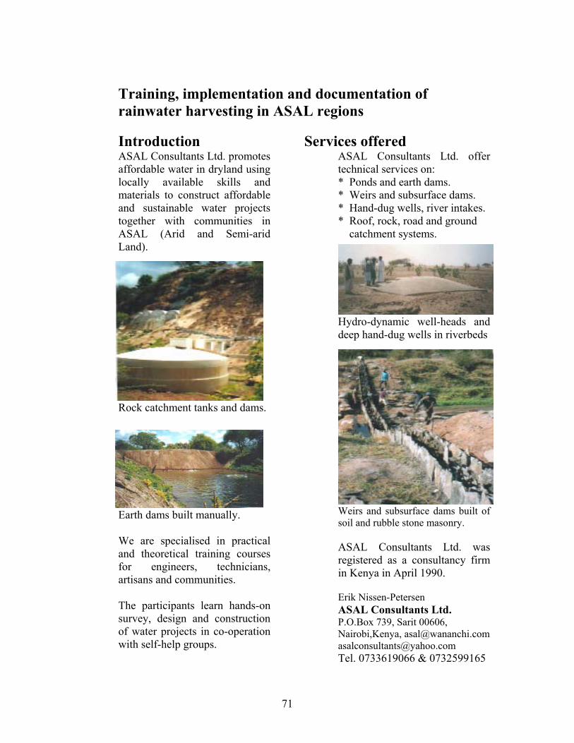
71
Training, implementation and documentation of rainwater harvesting in ASAL regions
Introduction ASAL Consultants Ltd. promotes affordable water in dryland using locally available skills and materials to construct affordable and sustainable water projects together with communities in ASAL (Arid and Semi-arid Land).
Rock catchment tanks and dams.
Earth dams built manually. We are specialised in practical and theoretical training courses for engineers, technicians, artisans and communities. The participants learn hands-on survey, design and construction of water projects in co-operation with self-help groups.
Services offered ASAL Consultants Ltd. offer technical services on: * Ponds and earth dams. * Weirs and subsurface dams. * Hand-dug wells, river intakes. * Roof, rock, road and ground catchment systems.
Hydro-dynamic well-heads and deep hand-dug wells in riverbeds
Weirs and subsurface dams built of soil and rubble stone masonry. ASAL Consultants Ltd. was registered as a consultancy firm in Kenya in April 1990. Erik Nissen-Petersen ASAL Consultants Ltd. P.O.Box 739, Sarit 00606, Nairobi,Kenya, [email protected] [email protected] Tel. 0733619066 & 0732599165

72