Water Solutions in the Oil & Gas Industry Up-stream Water ... · Up-stream Water Treatment...
35
Water Solutions in the Oil & Gas Industry Up-stream Water Treatment www.siemens.com/water-solutions Unrestricted © Siemens AG 2017
Transcript of Water Solutions in the Oil & Gas Industry Up-stream Water ... · Up-stream Water Treatment...
Water Solutionsin the Oil & Gas IndustryUp-stream Water Treatment
www.siemens.com/water-solutionsUnrestricted © Siemens AG 2017
Unrestricted © Siemens AG 2017Page 2 PD SLN WS
Water Treatment in the Oil & Gas Industry – Up-streamContent
• Produced Water Treatment Objectives• Primary Separation• Secondary Separation• Tertiary Separation• Reference Installations
ü acc. RoK Standardsü acc. Intl. Standards
Unrestricted © Siemens AG 2017Page 3 PD SLN WS
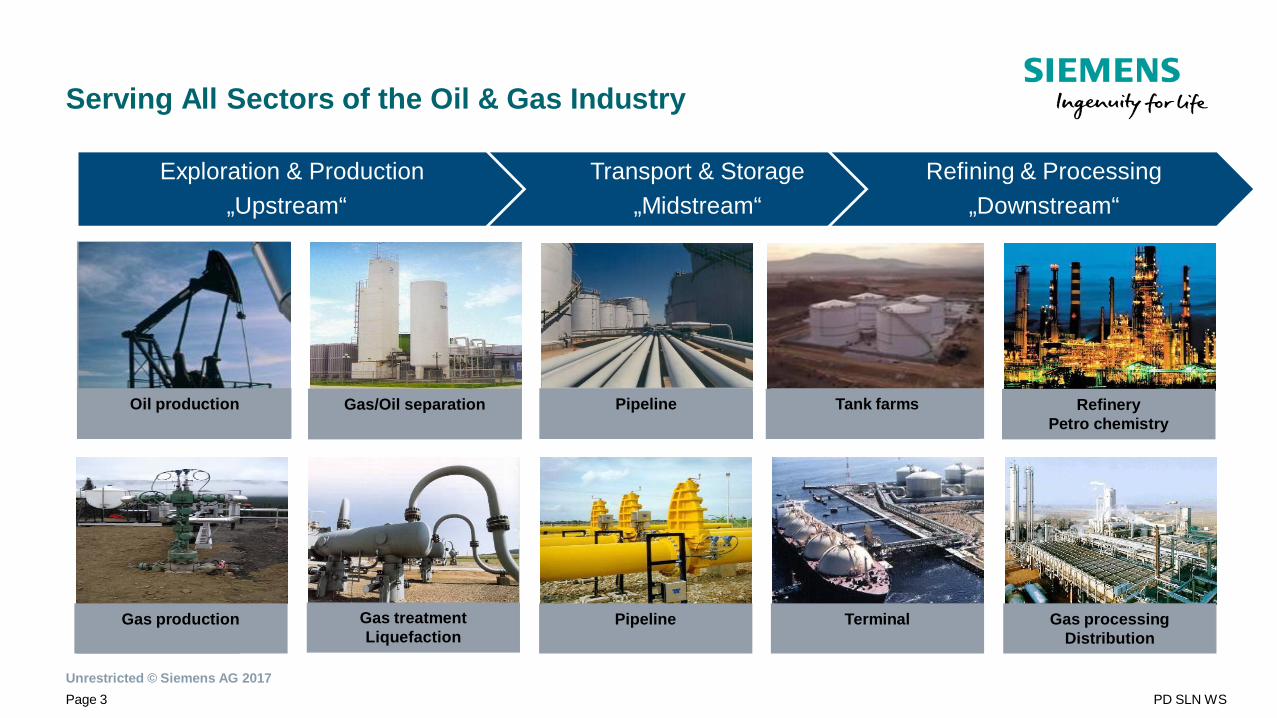
Serving All Sectors of the Oil & Gas Industry
Exploration & Production„Upstream“
Transport & Storage„Midstream“
Refining & Processing„Downstream“
Gas production
Oil production Gas/Oil separation Pipeline Tank farms RefineryPetro chemistry
Pipeline Terminal Gas processingDistribution
Gas treatmentLiquefaction
Gas production
Oil production Gas/Oil separation Pipeline Tank farms

Unrestricted © Siemens AG 2017Page 4 PD SLN WS
Treatment Objectives
Unrestricted © Siemens AG 2017Page 5 PD SLN WS
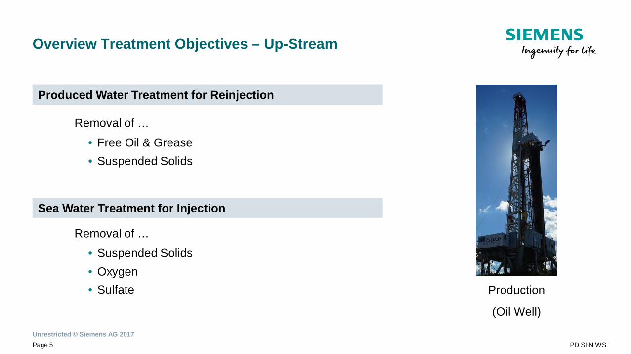
Overview Treatment Objectives – Up-Stream
Removal of …
• Free Oil & Grease• Suspended Solids
Removal of …
Removal of …
• Suspended Solids• Oxygen• Sulfate
Produced Water Treatment for Reinjection
Sea Water Treatment for Injection
Production
(Oil Well)
Unrestricted © Siemens AG 2017Page 6 PD SLN WS
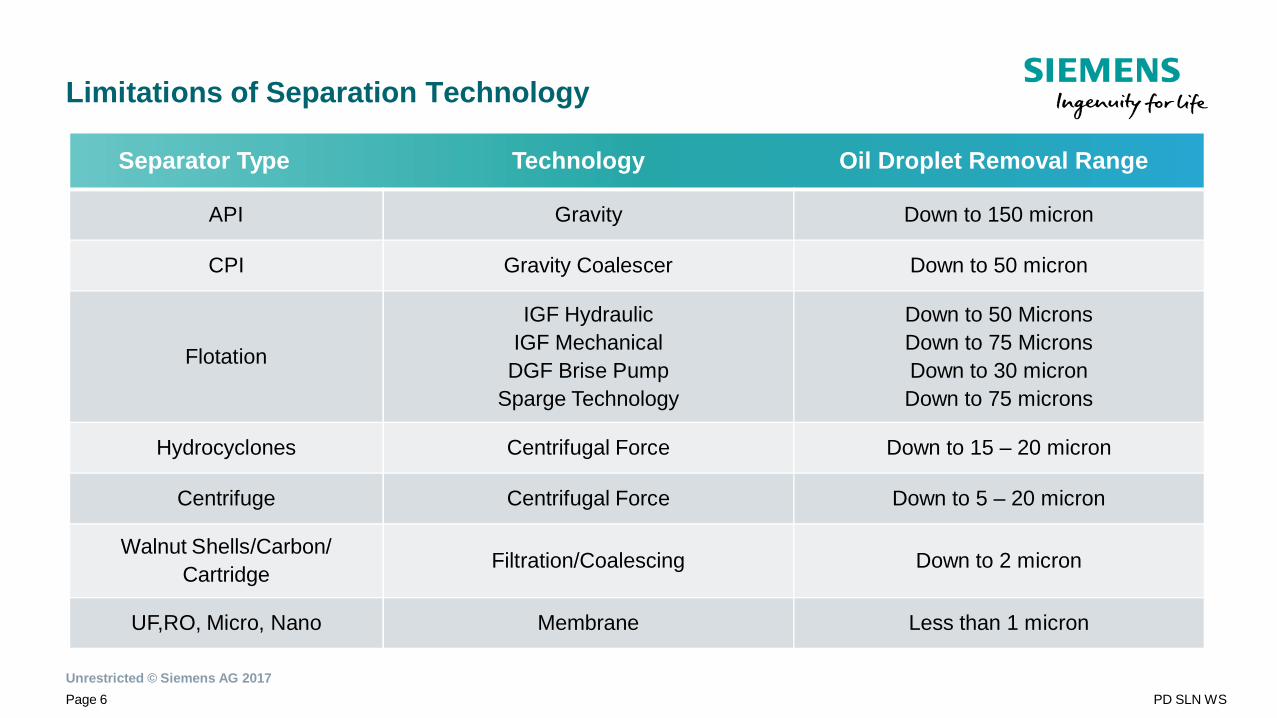
Limitations of Separation Technology
Separator Type Technology Oil Droplet Removal Range
API Gravity Down to 150 micron
CPI Gravity Coalescer Down to 50 micron
Flotation
IGF HydraulicIGF Mechanical
DGF Brise PumpSparge Technology
Down to 50 MicronsDown to 75 MicronsDown to 30 micronDown to 75 microns
Hydrocyclones Centrifugal Force Down to 15 – 20 micron
Centrifuge Centrifugal Force Down to 5 – 20 micron
Walnut Shells/Carbon/Cartridge Filtration/Coalescing Down to 2 micron
UF,RO, Micro, Nano Membrane Less than 1 micron
Unrestricted © Siemens AG 2017Page 7 PD SLN WS
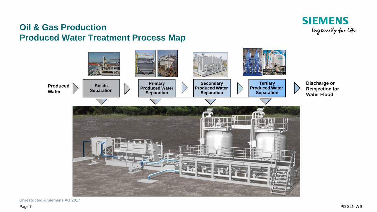
Oil & Gas ProductionProduced Water Treatment Process Map
Discharge orReinjection forWater Flood
ProducedWater
SolidsSeparation
PrimaryProduced Water
Separation
SecondaryProduced Water
Separation
TertiaryProduced Water
Separation
Unrestricted © Siemens AG 2017Page 8 PD SLN WS
Primary Separation
Unrestricted © Siemens AG 2017Page 9 PD SLN WS
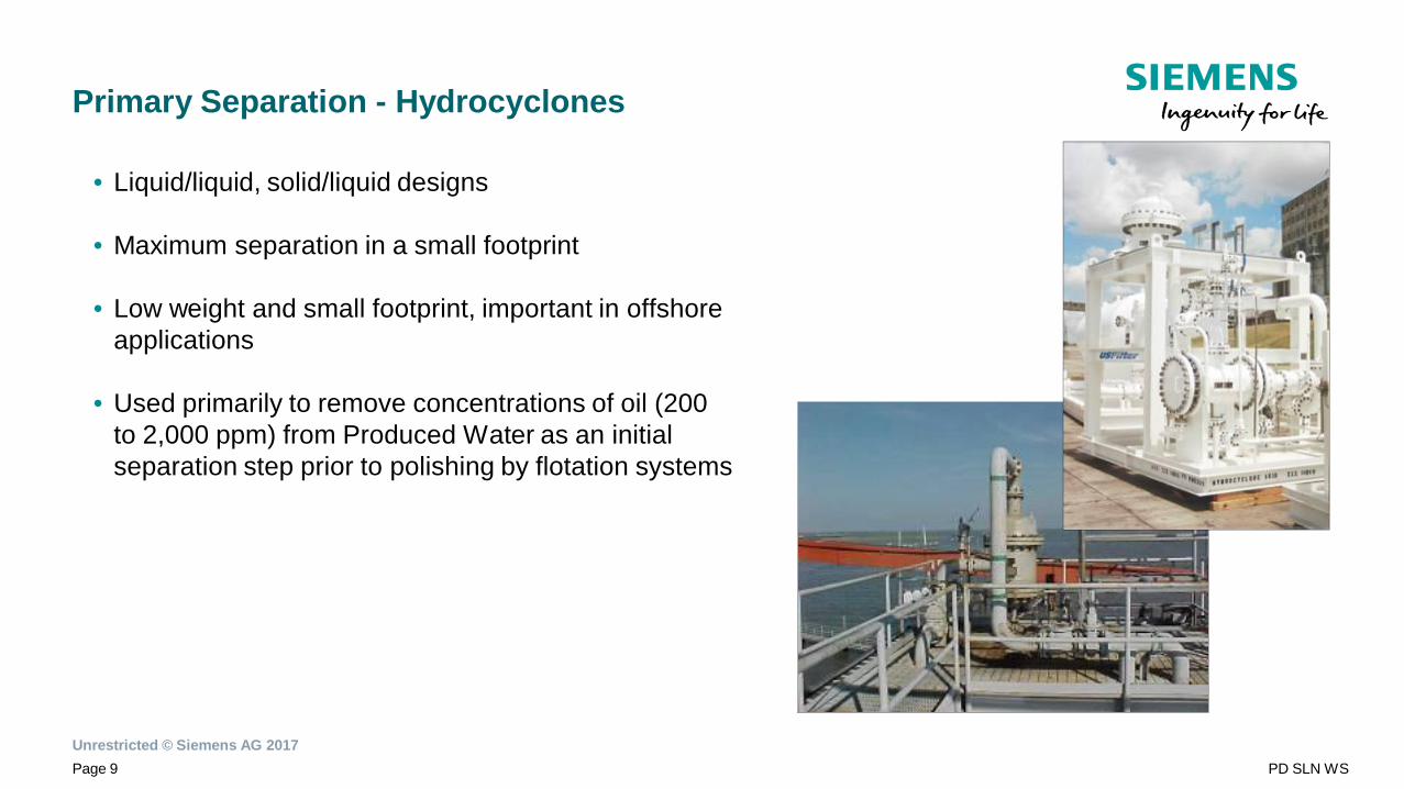
Primary Separation - Hydrocyclones
• Liquid/liquid, solid/liquid designs
• Maximum separation in a small footprint
• Low weight and small footprint, important in offshoreapplications
• Used primarily to remove concentrations of oil (200to 2,000 ppm) from Produced Water as an initialseparation step prior to polishing by flotation systems
Unrestricted © Siemens AG 2017Page 10 PD SLN WS
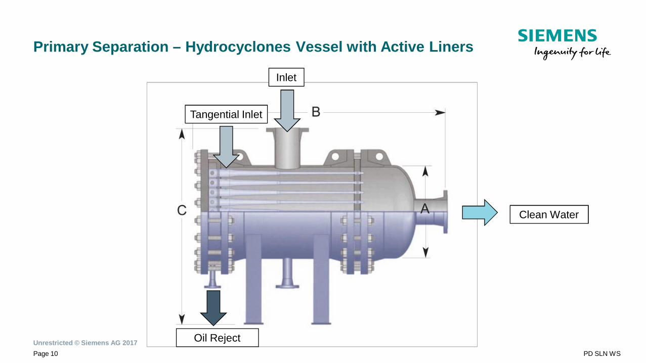
Primary Separation – Hydrocyclones Vessel with Active Liners
Tangential Inlet
Clean Water
Oil Reject
Inlet
Unrestricted © Siemens AG 2017Page 11 PD SLN WS
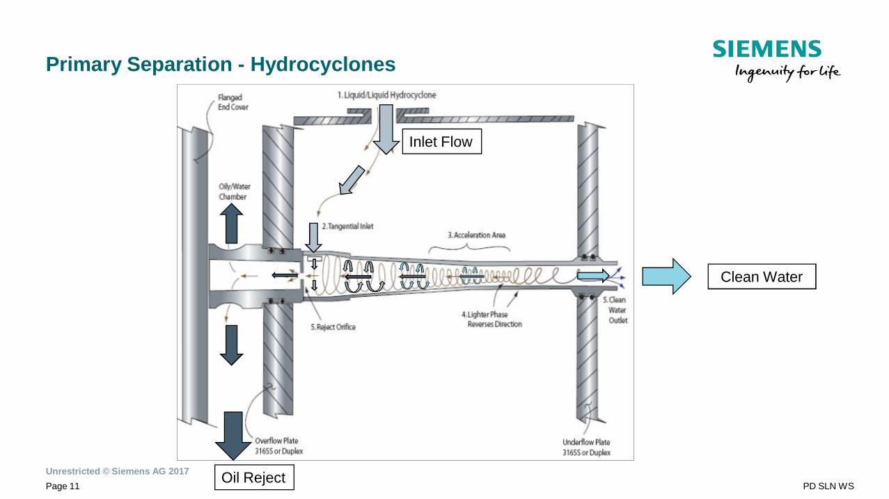
Primary Separation - Hydrocyclones
Oil Reject
Inlet Flow
Clean Water
Unrestricted © Siemens AG 2017Page 12 PD SLN WS
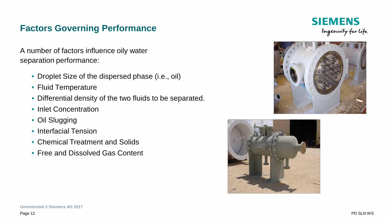
Factors Governing Performance
A number of factors influence oily waterseparation performance:
• Droplet Size of the dispersed phase (i.e., oil)• Fluid Temperature• Differential density of the two fluids to be separated.• Inlet Concentration• Oil Slugging• Interfacial Tension• Chemical Treatment and Solids• Free and Dissolved Gas Content
Unrestricted © Siemens AG 2017Page 13 PD SLN WS
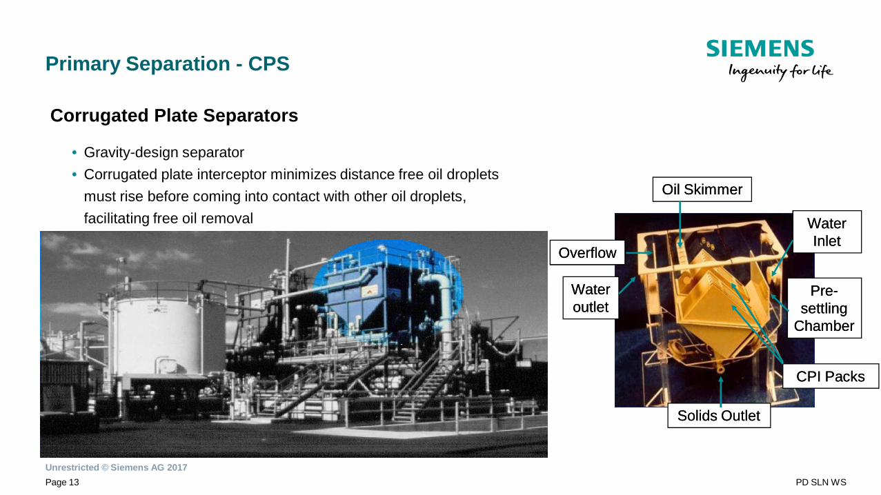
Primary Separation - CPS
Corrugated Plate Separators
• Gravity-design separator• Corrugated plate interceptor minimizes distance free oil droplets
must rise before coming into contact with other oil droplets,facilitating free oil removal WaterWater
InletInlet
PrePre--settlingsettling
ChamberChamber
CPI PacksCPI Packs
Solids OutletSolids Outlet
WaterWateroutletoutlet
OverflowOverflow
Oil SkimmerOil Skimmer
Unrestricted © Siemens AG 2017Page 14 PD SLN WS
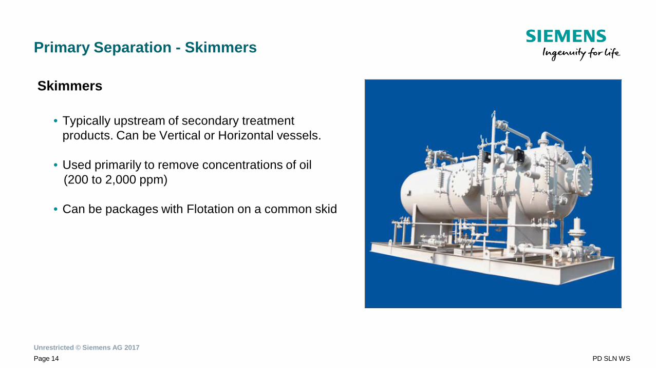
Primary Separation - Skimmers
Skimmers
• Typically upstream of secondary treatmentproducts. Can be Vertical or Horizontal vessels.
• Used primarily to remove concentrations of oil(200 to 2,000 ppm)
• Can be packages with Flotation on a common skid
Unrestricted © Siemens AG 2017Page 15 PD SLN WS
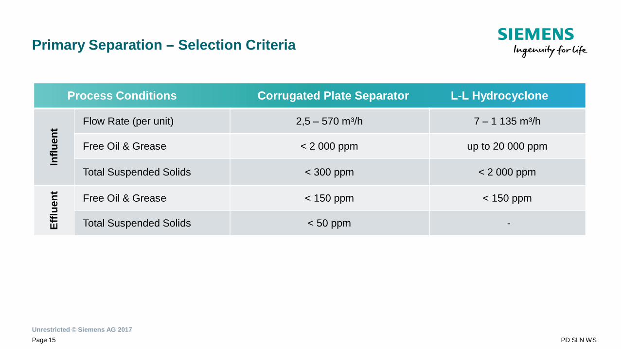
Primary Separation – Selection Criteria
Process Conditions Corrugated Plate Separator L-L Hydrocyclone
Influ
ent Flow Rate (per unit) 2,5 – 570 m³/h 7 – 1 135 m³/h
Free Oil & Grease < 2 000 ppm up to 20 000 ppm
Total Suspended Solids < 300 ppm < 2 000 ppm
Efflu
ent
Free Oil & Grease < 150 ppm < 150 ppm
Total Suspended Solids < 50 ppm -

Unrestricted © Siemens AG 2017Page 16 PD SLN WS
Secondary Separation
Unrestricted © Siemens AG 2017Page 17 PD SLN WS
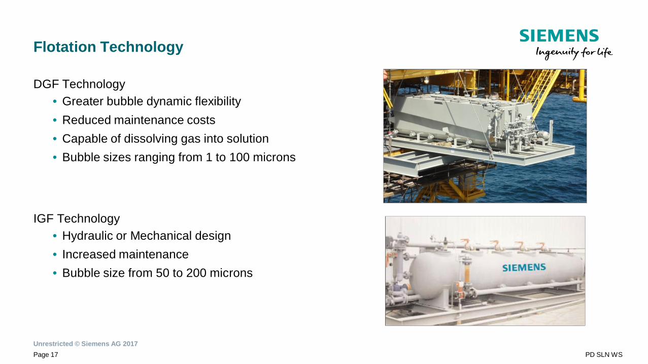
Flotation Technology
DGF Technology• Greater bubble dynamic flexibility• Reduced maintenance costs• Capable of dissolving gas into solution• Bubble sizes ranging from 1 to 100 microns
IGF Technology• Hydraulic or Mechanical design• Increased maintenance• Bubble size from 50 to 200 microns
Unrestricted © Siemens AG 2017Page 18 PD SLN WS
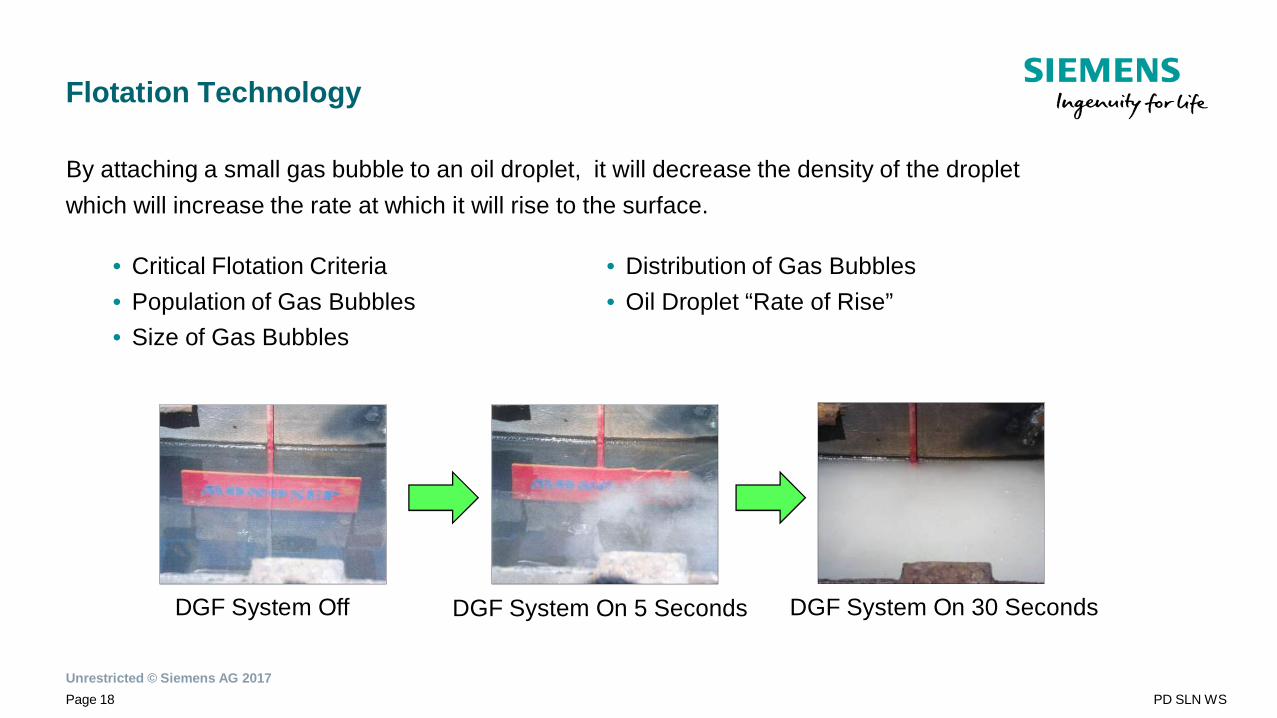
Flotation Technology
By attaching a small gas bubble to an oil droplet, it will decrease the density of the dropletwhich will increase the rate at which it will rise to the surface.
DGF System On 30 SecondsDGF System Off DGF System On 5 Seconds
• Critical Flotation Criteria• Population of Gas Bubbles• Size of Gas Bubbles
• Distribution of Gas Bubbles• Oil Droplet “Rate of Rise”
Unrestricted © Siemens AG 2017Page 19 PD SLN WS
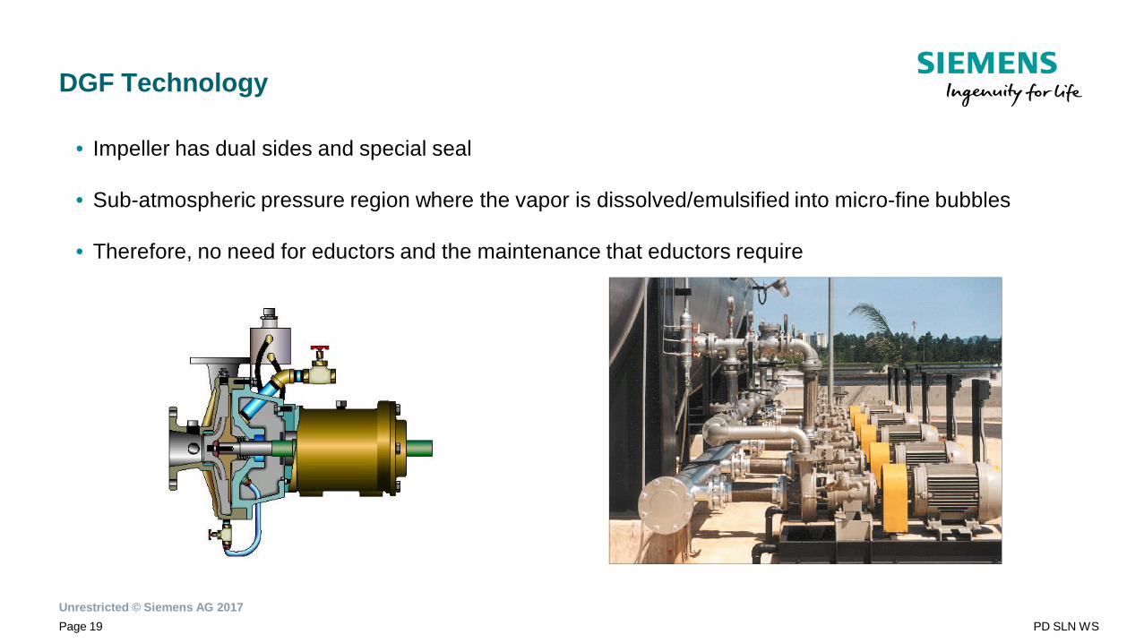
DGF Technology
• Impeller has dual sides and special seal
• Sub-atmospheric pressure region where the vapor is dissolved/emulsified into micro-fine bubbles
• Therefore, no need for eductors and the maintenance that eductors require
Unrestricted © Siemens AG 2017Page 20 PD SLN WS
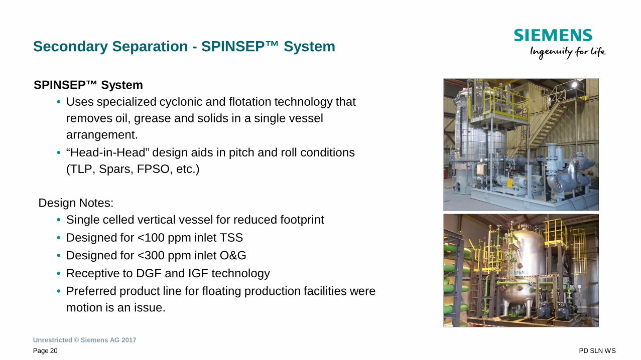
Secondary Separation - SPINSEP™ System
SPINSEP™ System• Uses specialized cyclonic and flotation technology that
removes oil, grease and solids in a single vesselarrangement.
• “Head-in-Head” design aids in pitch and roll conditions(TLP, Spars, FPSO, etc.)
Design Notes:• Single celled vertical vessel for reduced footprint• Designed for <100 ppm inlet TSS• Designed for <300 ppm inlet O&G• Receptive to DGF and IGF technology• Preferred product line for floating production facilities were
motion is an issue.
Unrestricted © Siemens AG 2017Page 21 PD SLN WS
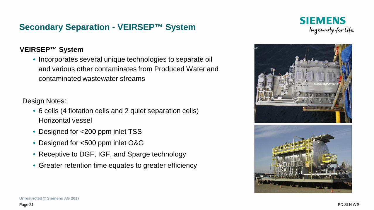
Secondary Separation - VEIRSEP™ System
VEIRSEP™ System• Incorporates several unique technologies to separate oil
and various other contaminates from Produced Water andcontaminated wastewater streams
Design Notes:• 6 cells (4 flotation cells and 2 quiet separation cells)
Horizontal vessel• Designed for <200 ppm inlet TSS• Designed for <500 ppm inlet O&G• Receptive to DGF, IGF, and Sparge technology• Greater retention time equates to greater efficiency
Unrestricted © Siemens AG 2017Page 22 PD SLN WS
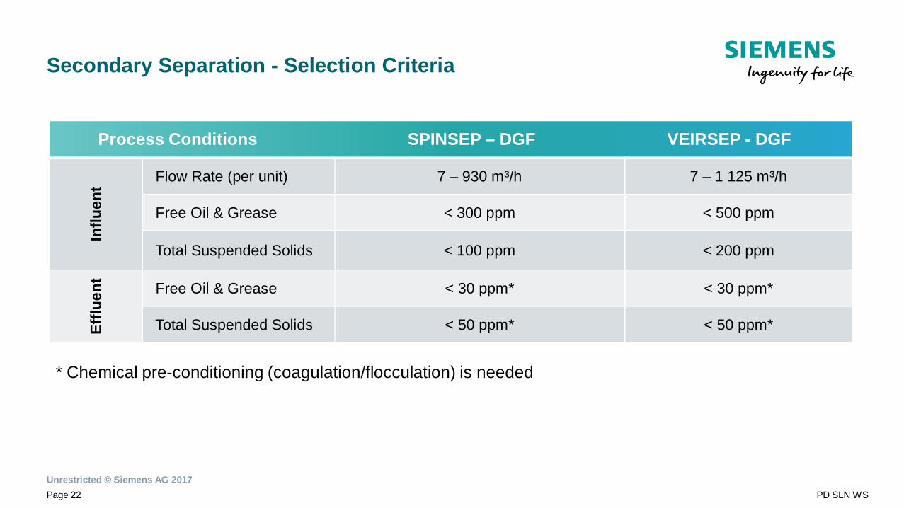
Secondary Separation - Selection Criteria
Process Conditions SPINSEP – DGF VEIRSEP - DGF
Influ
ent Flow Rate (per unit) 7 – 930 m³/h 7 – 1 125 m³/h
Free Oil & Grease < 300 ppm < 500 ppm
Total Suspended Solids < 100 ppm < 200 ppm
Efflu
ent
Free Oil & Grease < 30 ppm* < 30 ppm*
Total Suspended Solids < 50 ppm* < 50 ppm*
* Chemical pre-conditioning (coagulation/flocculation) is needed

Unrestricted © Siemens AG 2017Page 23 PD SLN WS
Tertiary Separation
XX.XX.20XX
Unrestricted © Siemens AG 2017Page 24 PD SLN WS
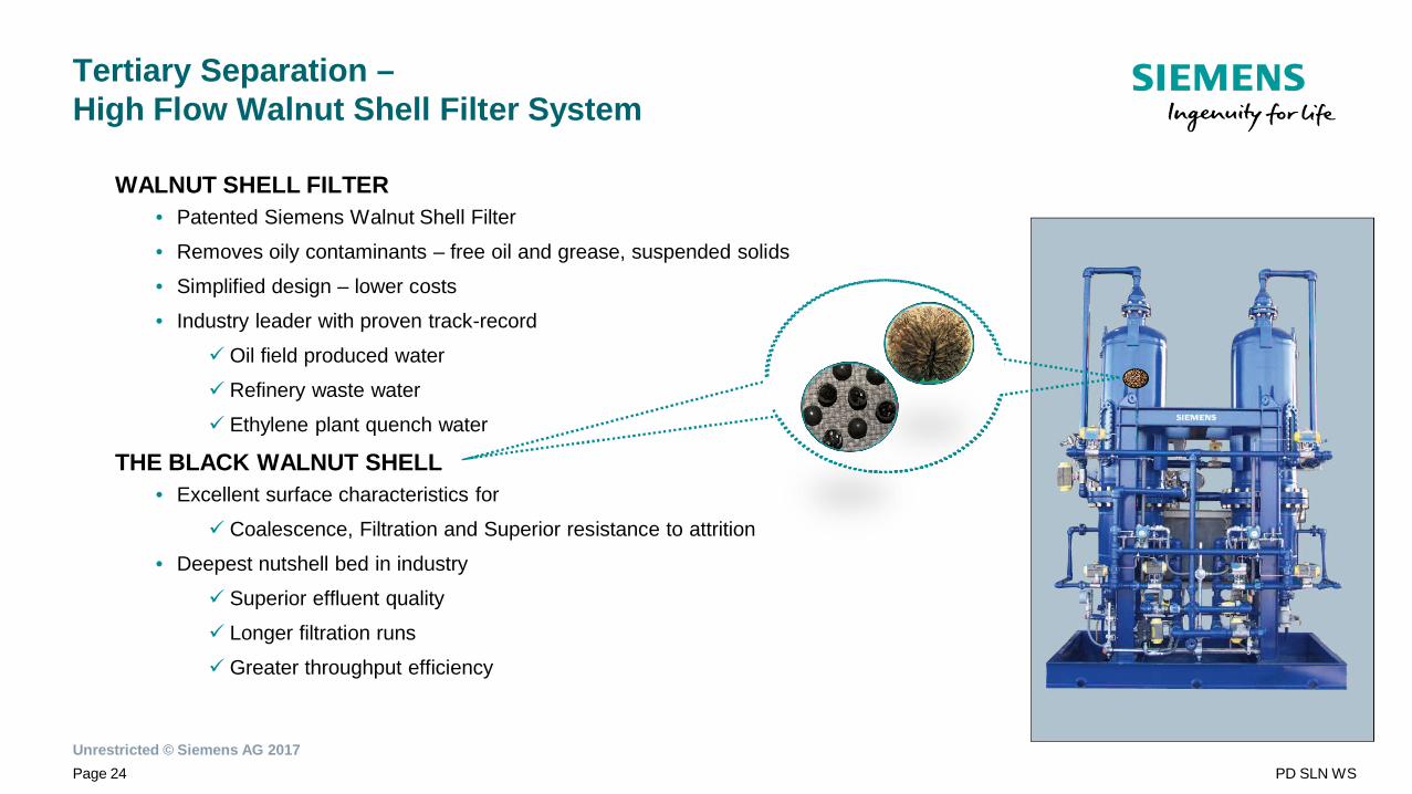
Tertiary Separation –High Flow Walnut Shell Filter System
WALNUT SHELL FILTER• Patented Siemens Walnut Shell Filter
• Removes oily contaminants – free oil and grease, suspended solids
• Simplified design – lower costs
• Industry leader with proven track-record
ü Oil field produced water
ü Refinery waste water
ü Ethylene plant quench water
THE BLACK WALNUT SHELL• Excellent surface characteristics for
ü Coalescence, Filtration and Superior resistance to attrition
• Deepest nutshell bed in industry
ü Superior effluent quality
ü Longer filtration runs
ü Greater throughput efficiency
Unrestricted © Siemens AG 2017Page 25 PD SLN WS
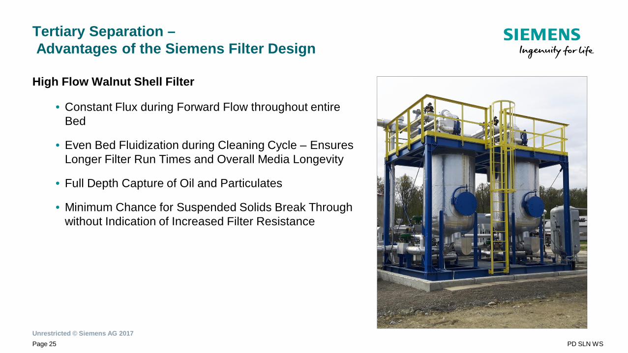
Tertiary Separation –Advantages of the Siemens Filter Design
High Flow Walnut Shell Filter
• Constant Flux during Forward Flow throughout entireBed
• Even Bed Fluidization during Cleaning Cycle – EnsuresLonger Filter Run Times and Overall Media Longevity
• Full Depth Capture of Oil and Particulates
• Minimum Chance for Suspended Solids Break Throughwithout Indication of Increased Filter Resistance
Unrestricted © Siemens AG 2017Page 26 PD SLN WS
Tertiary Separation –Advantages of the Siemens Filter Design
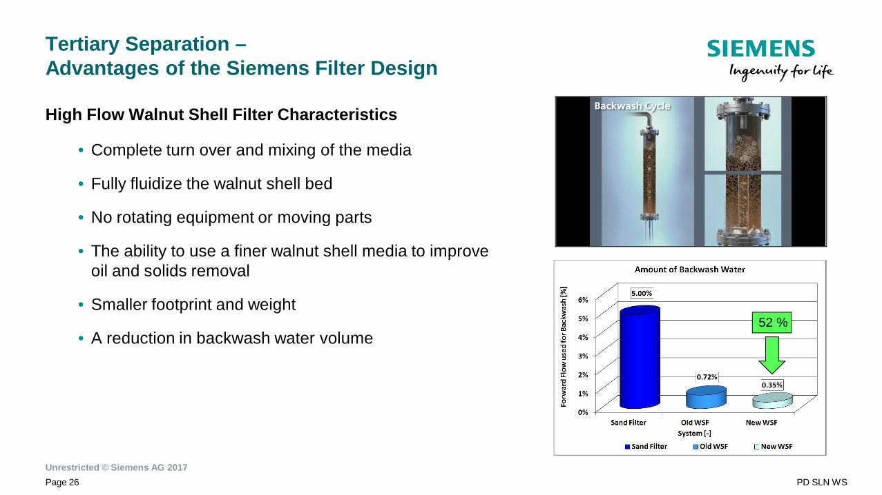
High Flow Walnut Shell Filter Characteristics
• Complete turn over and mixing of the media
• Fully fluidize the walnut shell bed
• No rotating equipment or moving parts
• The ability to use a finer walnut shell media to improveoil and solids removal
• Smaller footprint and weight
• A reduction in backwash water volume52 %
Unrestricted © Siemens AG 2017Page 27 PD SLN WS
Tertiary Separation –Siemens Walnut Shell Filtration Re-Design
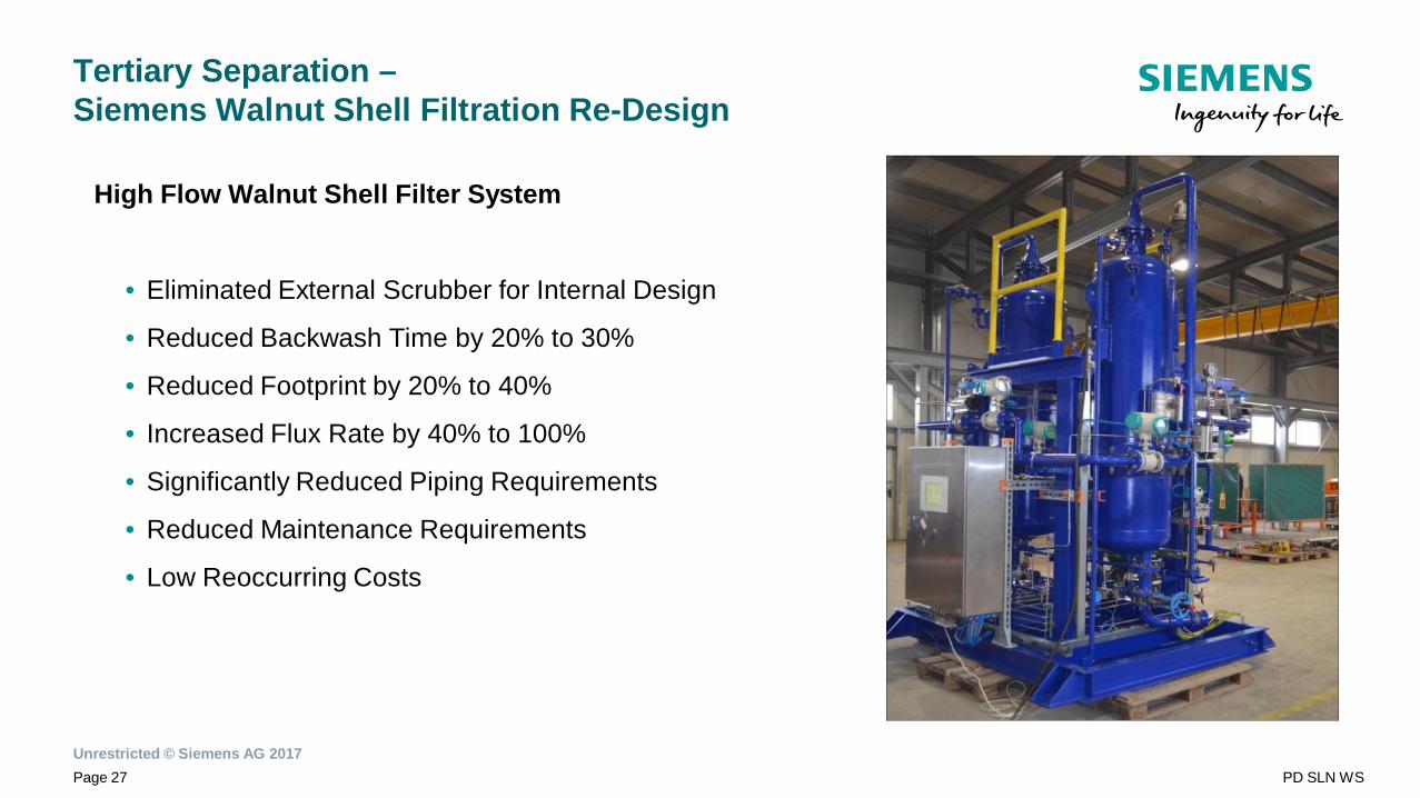
High Flow Walnut Shell Filter System
• Eliminated External Scrubber for Internal Design
• Reduced Backwash Time by 20% to 30%
• Reduced Footprint by 20% to 40%
• Increased Flux Rate by 40% to 100%
• Significantly Reduced Piping Requirements
• Reduced Maintenance Requirements
• Low Reoccurring Costs
Unrestricted © Siemens AG 2017Page 28 PD SLN WS
Tertiary Separation –Key Facts of the High Flow Walnut Shell Filter (1)
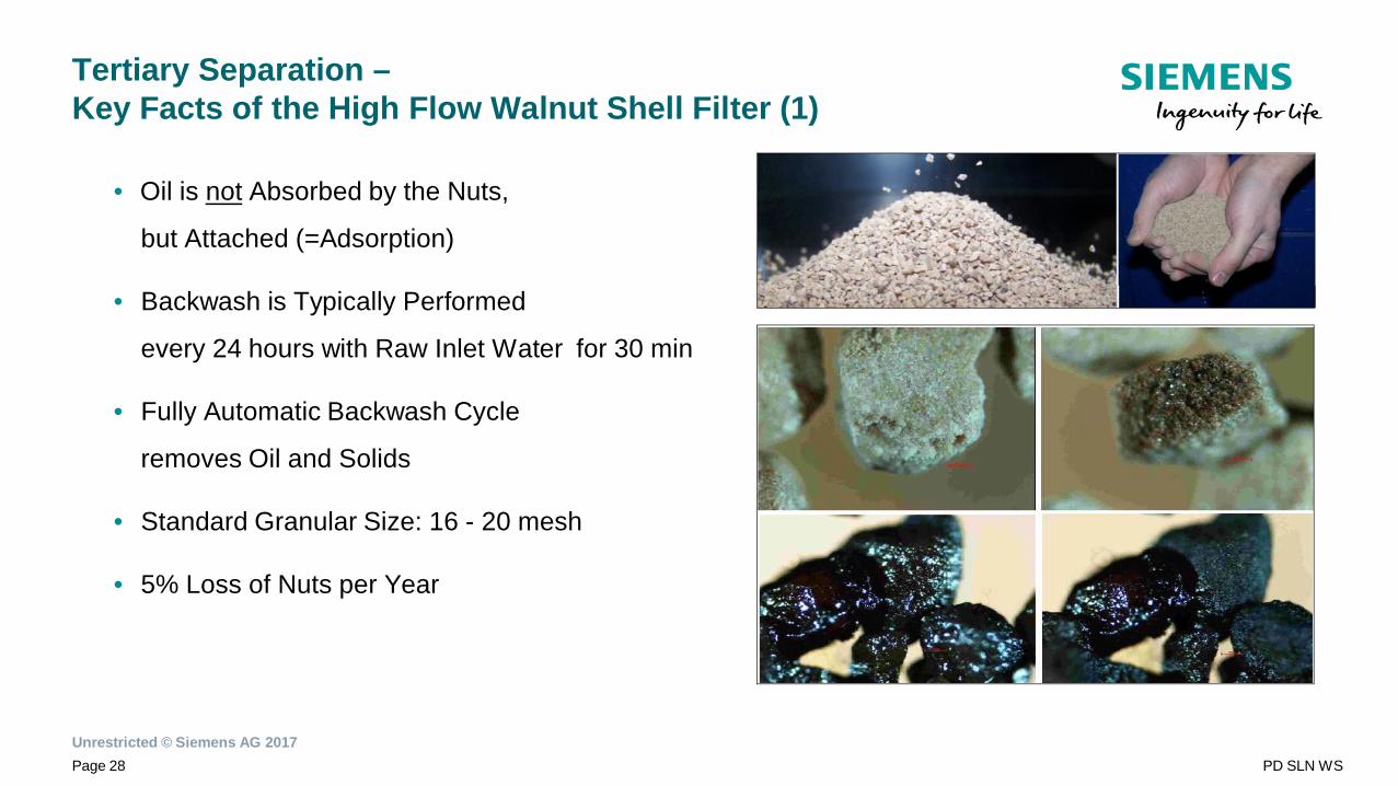
• Oil is not Absorbed by the Nuts,
but Attached (=Adsorption)
• Backwash is Typically Performed
every 24 hours with Raw Inlet Water for 30 min
• Fully Automatic Backwash Cycle
removes Oil and Solids
• Standard Granular Size: 16 - 20 mesh
• 5% Loss of Nuts per Year
Unrestricted © Siemens AG 2017Page 29 PD SLN WS
Tertiary Separation –Key Facts of the High Flow Walnut Shell Filter (2)
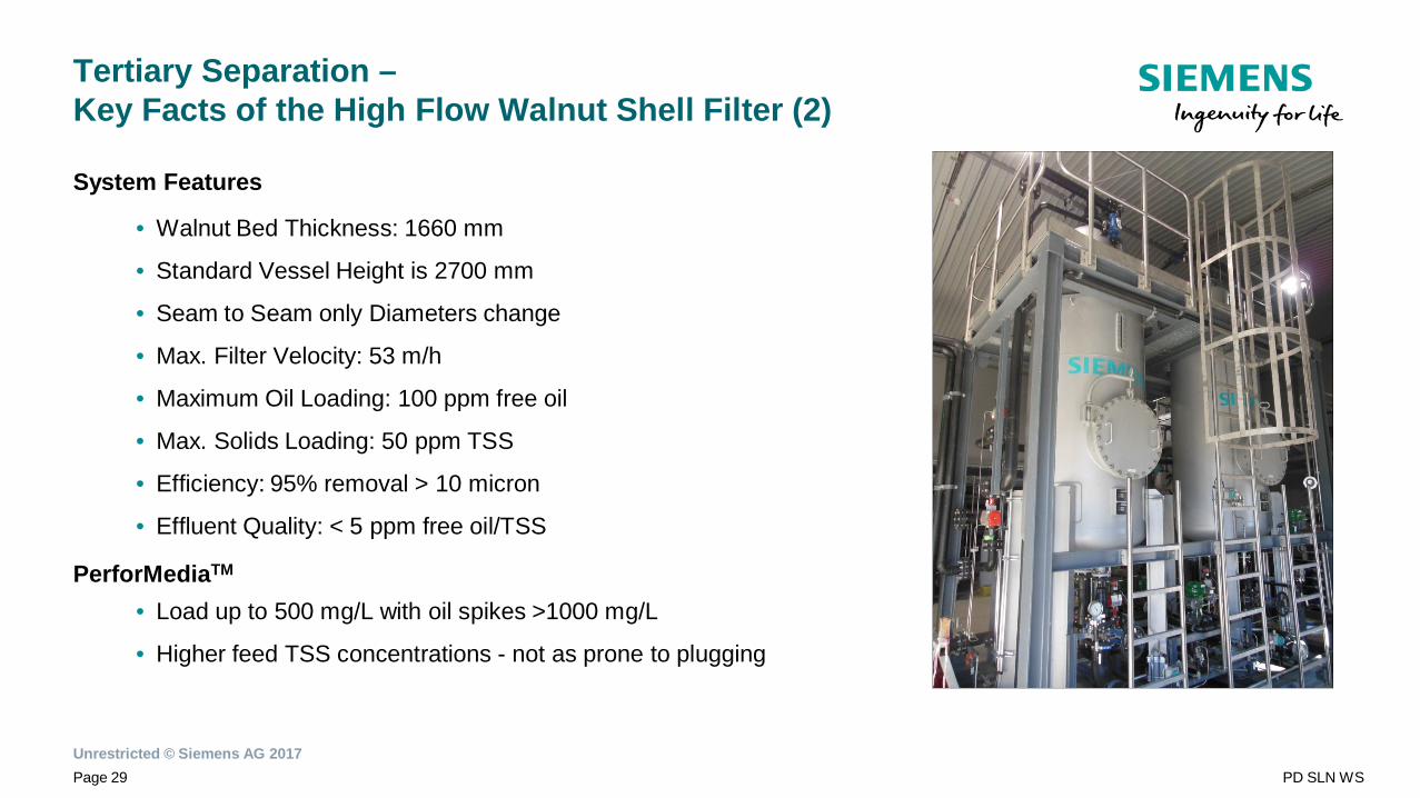
System Features
• Walnut Bed Thickness: 1660 mm
• Standard Vessel Height is 2700 mm
• Seam to Seam only Diameters change
• Max. Filter Velocity: 53 m/h
• Maximum Oil Loading: 100 ppm free oil
• Max. Solids Loading: 50 ppm TSS
• Efficiency: 95% removal > 10 micron
• Effluent Quality: < 5 ppm free oil/TSS
PerforMediaTM
• Load up to 500 mg/L with oil spikes >1000 mg/L
• Higher feed TSS concentrations - not as prone to plugging
Unrestricted © Siemens AG 2017Page 30 PD SLN WS
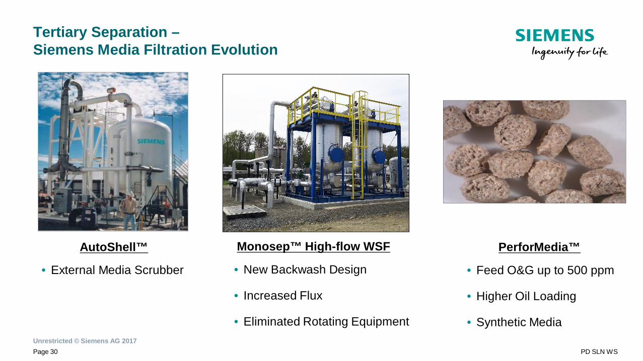
Tertiary Separation –Siemens Media Filtration Evolution
AutoShell™
• External Media Scrubber
Monosep™ High-flow WSF
• New Backwash Design
• Increased Flux
• Eliminated Rotating Equipment
PerforMedia™
• Feed O&G up to 500 ppm
• Higher Oil Loading
• Synthetic Media
Unrestricted © Siemens AG 2017Page 31 PD SLN WS
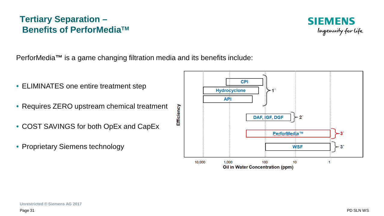
PerforMedia™ is a game changing filtration media and its benefits include:
• ELIMINATES one entire treatment step
• Requires ZERO upstream chemical treatment
• COST SAVINGS for both OpEx and CapEx
• Proprietary Siemens technology
Tertiary Separation –Benefits of PerforMediaTM
Unrestricted © Siemens AG 2017Page 32 PD SLN WS
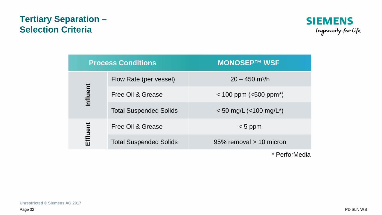
Tertiary Separation –Selection Criteria
Process Conditions MONOSEP™ WSF
Influ
ent Flow Rate (per vessel) 20 – 450 m³/h
Free Oil & Grease < 100 ppm (<500 ppm*)
Total Suspended Solids < 50 mg/L (<100 mg/L*)
Efflu
ent
Free Oil & Grease < 5 ppm
Total Suspended Solids 95% removal > 10 micron
* PerforMedia

Unrestricted © Siemens AG 2017Page 33 PD SLN WS
Reference Installations
XX.XX.20XX Autor / Abteilung
Unrestricted © Siemens AG 2017Page 34 PD SLN WS
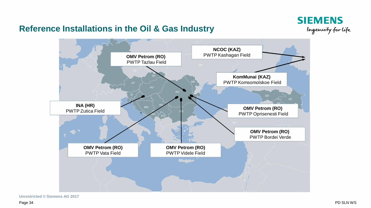
Reference Installations in the Oil & Gas Industry
IL
CZ
AT
SK
HU
SIHR
BIHRS
MN KO
BG
RO
UA
MD
TK
GEAZ
AR
AZ
NCOC (KAZ)PWTP Kashagan Field
INA (HR)PWTP Zutica Field
OMV Petrom (RO)PWTP Vata Field
OMV Petrom (RO)PWTP Videle Field
OMV Petrom (RO)PWTP Tazlau Field
OMV Petrom (RO)PWTP Oprisenesti Field
KomMunai (KAZ)PWTP Komsomolskoe Field
OMV Petrom (RO)PWTP Bordei Verde
Unrestricted © Siemens AG 2017Page 35 PD SLN WS
Water Management in the O&G IndustryUp-stream Water Treatment
Dr. Robert Vranitzky MBAHead of Water SolutionsWater Solutions / Austria / PD SLN WS
Siemensstraße 901210 Vienna
Fax: +43 51707 51337Mobil: +43 664 80117 22338
E-Mail:[email protected]
www.siemens.com/water-solutions