WATER SOFTENER ASSEMBLY INSTRUCTIONS - … SOFTENER ASSEMBLY INSTRUCTIONS ... until you have put the...
84
1 WATER SOFTENER ASSEMBLY INSTRUCTIONS We think installing our softeners is very easy (if you are somewhat mechanically inclined and have a little experience doing basic plumbing). Note: If you have an electric water heater we recommend that you turn off the electricity to the heater while installing softener. Once you are satisfied with the installation, turn on a few hot and cold- water faucets, and let them run. Once you are certain that there is no more air in your pipes, then turn the electricity back on to the water heater. Step 1: Location of your softener is important. It should be in a protected dry, level and non-freezing area (34-120 degrees F). The 2 tanks should be set close to each other. The square tank with the black lid is your brine tank (for softener salt or potassium chloride) and it is the tank that you will have to refill sometimes, so make it the more accessible of the 2 tanks. Do not put salt in this tank until you have put the softener into service and have tested the cycles. Step 2: You will need a standard outlet that is not controlled by a switch, which can be 50 feet from your softener. Step 3: You will need a drain for the backwashing cycles. This should be no longer than 20 feet from the softener. Refer to the Autotrol manual for exceptions and more details. You will need to purchase this flexible 1/2 i.d. plastic pipe (can be vinyl, polyethylene polybutylene, etc. and same size will be used in step 8). This backwashing drain line will be under pressure when the backwash cycle is working. Make sure the drain line is secured. The drain line will need to drain into a drain, which should be a minimum of 1 1/2” size, and ideally be below the top of the head of your softener. Local codes should be adhered to. Note: Never connect the drain line directly into a drain. Allow an airgap between the drainline and waste line to prevent possibility of back- siphonage. Step 4: Once you have determined the exact location of your softener, it is time to fill the media/mineral tank (taller of the 2) with the furnished media (looks like brown tiny beads and has a consistency of wet sand). The distributor tube should be in the mineral tank - screen intake would be at the bottom; open end will be at the top. The open end should be sticking 1 1/4" out of the mineral tank. The screen intake should be resting on the bottom, centered. There should be a plug in the open end of the distributor tube. This is to keep any media from falling into the distributor tube while pouring the media into the mineral tank.
Transcript of WATER SOFTENER ASSEMBLY INSTRUCTIONS - … SOFTENER ASSEMBLY INSTRUCTIONS ... until you have put the...

1
WATER SOFTENER ASSEMBLY INSTRUCTIONS
We think installing our softeners is very easy (if you are somewhat mechanically inclined and have a little experience doing basic plumbing). Note: If you have an electric water heater we recommend that you turn off the electricity to the heater while installing softener. Once you are satisfied with the installation, turn on a few hot and cold-water faucets, and let them run. Once you are certain that there is no more air in your pipes, then turn the electricity back on to the water heater. Step 1: Location of your softener is important. It should be in a protected dry, level and non-freezing area (34-120 degrees F). The 2 tanks should be set close to each other. The square tank with the black lid is your brine tank (for softener salt or potassium chloride) and it is the tank that you will have to refill sometimes, so make it the more accessible of the 2 tanks. Do not put salt in this tank until you have put the softener into service and have tested the cycles. Step 2: You will need a standard outlet that is not controlled by a switch, which can be 50 feet from your softener. Step 3: You will need a drain for the backwashing cycles. This should be no longer than 20 feet from the softener. Refer to the Autotrol manual for exceptions and more details. You will need to purchase this flexible 1/2 i.d. plastic pipe (can be vinyl, polyethylene polybutylene, etc. and same size will be used in step 8). This backwashing drain line will be under pressure when the backwash cycle is working. Make sure the drain line is secured. The drain line will need to drain into a drain, which should be a minimum of 1 1/2” size, and ideally be below the top of the head of your softener. Local codes should be adhered to. Note: Never connect the drain line directly into a drain. Allow an airgap between the drainline and waste line to prevent possibility of back- siphonage. Step 4: Once you have determined the exact location of your softener, it is time to fill the media/mineral tank (taller of the 2) with the furnished media (looks like brown tiny beads and has a consistency of wet sand). The distributor tube should be in the mineral tank - screen intake would be at the bottom; open end will be at the top. The open end should be sticking 1 1/4" out of the mineral tank. The screen intake should be resting on the bottom, centered. There should be a plug in the open end of the distributor tube. This is to keep any media from falling into the distributor tube while pouring the media into the mineral tank.

2
Place the funnel (provided) into the mineral tank, and begin to put the media into the mineral tank. Be careful to keep the distributor tube centered as best you can, while filling. There should only be enough media to fill the tank about ½ to 2/3 full. The mineral tank should not be filled to the top. It is necessary for the media to have room to move during the backwash cycle. An easy (but slower) way to fill the mineral tank is to take a small scoop and pour the media into the funnel. The media beads tend to stick to the funnel so by filling slowly the media will go into the tank easier. Once the filling of the mineral tank is completed, carefully remove the plug from the distributor tube. Do not pull upwards on the distributor tube. The control valve (head) now must be screwed onto the mineral tank. Be sure the large O-ring is in place, and lubricated it with some of the grease provided in the by-pass valve kit box. As you start to screw the control valve onto the tank, make sure the hole in the center of the control valve fits over the distributor tube. NO pipe dope should be used on the threads. The control valve should be hand tightened, snugly, clockwise. Step 5: You are now ready to install the bypass valve to the control valve. Follow the instructions in the box. The in and out arrows on the bypass valve should be pointing the same direction as the in/out arrows on the outside of the control valve. The arrows are molded into the plastic on both the bypass valve and the control valve. Step 6: Water connections to and from softener will now be connected to the bypass 1 1/4"IPS male threads by using the two 1 1/4" Female nuts provided. Slip one 1 1/4" female nut over one of the flanged tailpieces, so that the tube is sticking through the nut and the flanged piece is resting on the inside of the female threaded part of the nut. Use one 1 3/4" o.d. rubber washer to fit into the female part of the nut on top of the flanged tailpiece and screw the nut onto the 1 1/4" IPS male threads on the control valve. Do the same for the other side. Step 7: Between the valve and the brine tank you will need to connect the furnished 3/8” O.D. tubing. One end is to the fitting on the clear air check on the valve (255 valve only), and the other end attaches to the elbow fitting inside the brine tank. Pass the tubing through the hole and connect the fitting entirely inside the brine tank. Do not use the fitting in the brine tank as a “bulkhead” fitting (i.e. fastening the nut on the outside of the brine tank) – it must be connected entirely inside the brine tank. Hand tightening is all that should be needed. Step 8: Brine tank Overflow. Attach 1/2" i.d. plastic tubing to the fitting from the brine tank and run to a drain. This drain line will not be under pressure. DO NOT tie into the backwash drain line! This line should be higher than your drain line. Overflow drain line must be a separate line from fitting to the floor-drain, sewer, tub, etc. Now follow the instructions in the Autotrol manual for putting the softener into service. NOTES ON SALT: Your brine tank will hold about 250 pounds of softer salt (about six 40-lb bags, or five 50-lb bags. We recommend a high quality pellet-type salt – look for a low “insoluble” level (insoluble is a nice word for dirt). Potassium chloride salt substitute can be used as well, with no adjustments needed. DO NOT ADD SALT UNTIL YOU HAVE COMPLETED THE SECTION ON PUTTING THE UNIT INTO SERVICE!

3
NOTES ON PROGRAMMING: You will need to program three items into your Autotrol computer control: current time, capacity, and water hardness. You also need to set the salt dial to the proper setting (except Logix and 960). Refer to your manual for details. When setting the capacity, you can take advantage of better salt efficiencies by setting them at a lower capacity than the peak. It will regenerate slightly more often, but the salt savings (up to 60% less salt) make it worth it. The chart in the Autotrol manual will show you the options. One cubic foot (1.0 ft3) units have a peak capacity of 32,000 grains. We suggest that you program "24" (for 24,000 grains) and the salt setting to 8.5. One and a half cubic foot (1.5 ft3) units have a peak capacity of 48,000 grains. We suggest you program the capacity to “35” and set the salt setting to 12 (set it at 6 on 460i units –they have the “XS” extra salt cam which doubles the amount of salt – you need to cut the amount shown in the chart in half). Two cubic foot (2.0 ft3) units have a peak capacity of 64,000 grains. We suggest you program the capacity to “40” and set the salt setting to 12 (set it at 6 on 460i units –they have the “XS” extra salt cam which doubles the amount of salt – you need to cut the amount shown in the chart in half). If you do not know your hardness number, call your water department, or send us a water sample. If your water department gives you the hardness number in milligrams per liter (mg/l) or in parts per million (ppm) you need to convert it to grains per gallon by dividing the number by 17.1. Other Notes: If using copper pipe, we recommend using type L copper. Type L is thicker than type M copper. Caution: A common problem for beginners when soldering onto the copper tailpieces is overheating them, melting the plastic nuts that connect to the bypass valve. We recommend that you wrap a wet rag around the nuts and tailpieces to keep the heat away. Also use care when tightening the tailpiece nuts so you do not crack them! Important: Be sure you double-check the inlet and outlet arrows on your softener before soldering! Remember that your pipes and water heater contain hard water, so it will take a few days until your water is 100% soft. Draining your water heater can hasten this. This also will remove any build up sediment (you are supposed to do this annually). Remember to now not use as much soap for dishwashing, laundry, etc. etc. No need for it! Many people report needing to use only about 1/3 to 1/2 as much as they previously needed. Remember to check with local code officials and install per local code.
GENERAL WARNINGS AND SAFETY INFORMATION
Electrical
There are no user-servicable parts in the AC adapter, motor, or controller. In the event of a failure, these should be replaced.
• All electrical connections must be completed according to local codes.
• Use only the power AC adapter that is supplied.
• The power outlet must be grounded.
• To disconnect power, unplug the AC adapter from its power source.
Mechanical
• Do not use petroleum based lubricants such as vaseline, oils, or hydrocarbon based lubricants. Use only 100% silicone lubricants.
• All plastic connections should be hand tightened. Teflon tape may be used on connections that do not use an O-ring seal. Do not use pliers or pipe wrenches.
• All plumbing must be completed according to local codes.
• Soldering near the drain line should be done before connecting the drain line to the valve. Excessive heat will cause interior damage to the valve.
• Observe drain line requirements.
• Do not use lead-based solder for sweat solder connections.
• The drain line must be a minimum of 1/2-inch diameter. Use 3/4-inch pipe if the backwash flow rate is greater than 7 GPM (26.5 Lpm) or the pipe length is greater than 20 feet (6 m).
• Do not support the weight of the system on the control valve fittings, plumbing, or the bypass.
• It is not recommended to use sealants on the threads. Use Teflon* tape on the threads of the 1-inch NPT elbow, the drain line connections, and other NPT threads.
*Teflon is a trademark of E.I. duPont de Nemours.
B - 2 Rev A

General
• Observe all warnings that appear in this manual.
• Keep the media tank in the upright position. Do not turn upside down or drop. Turning the tank upside down will cause media to enter the valve.
• Operating ambient temperature is between 34°F (1°C) and 120°F (49°C).
• Operating water temperature is between 34°F (1°F) and 100°F (38°C).
• Working water pressure range is 20 to 120 psi (1.38 to 8.27 bar). In Canada the acceptable working water pressure range is 20 to 100 psi (1.38 to 6.89 bar).
• Use only regenerant salts designed for water softening. Do not use ice melting, block, or rock salts.
• Follow state and local codes for water testing. Do not use water that is microbiologically unsafe or of unknown quality.
• When filling media tank, do not open water valve completely. Fill tank slowly to prevent media from exiting the tank.
• When installing the water connection (bypass or manifold) connect to the plumbing system first. Allow heated parts to cool and cemented parts to set before installing any plastic parts. Do not get primer or solvent on O-rings, nuts, or the valve.
GENERAL WARNINGS AND SAFETY INFORMATION B - 3Rev A

VALVE FEATURES
Figure 1255 Valve Identification
Check Ball
Air Check
Regenerant Tank
Refill Controller
Injector and Cap
Outlet
Inlet
Drain
Backwash Locking BarInjector
Valve DiscsCamshaft
Drain ControlScreen Filter
Manifold
Motor
Optical SensorControl ModuleMount
One Piece Valve
Tube Connection
Connection
Disc Spring
B - 4 Rev A
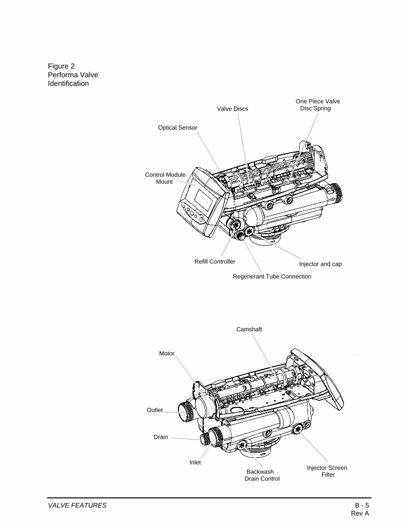
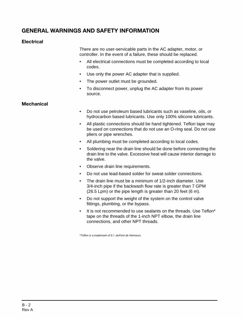
Figure 2Performa Valve Identification
Refill Controller
Regenerant Tube Connection
Injector and cap
Valve Discs
Outlet
Drain
Inlet
BackwashInjector Screen
Camshaft
Drain ControlFilter
Control ModuleMount
One Piece ValveDisc Spring
Motor
Optical Sensor
VALVE FEATURES B - 5Rev A

Figure 3700 Series Controller Identification
Time & Day
Regen Time & Day
Salt
SU MO TU WE TH FR SA DAYS
LBS
PMMIN
KG
x100x2
PHC
Capacity
Hardness
LCD Display
Manual Regen ButtonDown Button
Set Button Up Button
Lockout Connection (772 only)
740/760, 742/762) Turbine Input or Dry Contact Signal Input
716 Sensor Input
Main Motor & Optical Sensor Connection
AC Adapter (low voltage) Input
Chlorine Generator Outlet (EU and 742/762 versions only)
Secondary Valve Motor Control (772 only)
B - 6 Rev A

LOCATION SELECTIONLocation of a water treatment system is important. The following conditions are required:
• Level platform or floor
• Room to access equipment for maintenance and adding regenerant (salt) to tank.
• Ambient temperatures over 34°F (1°C) and below 120°F (49°C).
• Water pressure below 120 psi (8.27 bar) and above 20 psi (1.4 bar).
• In Canada the water pressure must be below 100 psi (6.89 bar).
• Constant electrical supply to operate the controller.
• Total minimum pipe run to water heater of ten feet (three meters) to prevent backup of hot water into system.
• Local drain for discharge as close as possible.
• Water line connections with shutoff or bypass valves.
• Must meet any local and state codes for site of installation.
• Valve is designed for minor plumbing misalignments. Do not support weight of system on the plumbing.
• Be sure all soldered pipes are fully cooled before attaching plastic valve to the plumbing.
OUTDOOR LOCATIONS
When the water conditioning system is installed outdoors, several items must be considered.
• Moisture — The valve and 700 controller are rated for NEMA 3 locations. Falling water should not affect performance.The system is not designed to withstand extreme humidity or water spray from below. Examples are: constant heavy mist, near corrosive environment, upwards spray from sprinkler.
• Direct Sunlight — The materials used will fade or discolor over time in direct sunlight. The integrity of the materials will not degrade to cause system failures.If it is necessary to locate the conditioner in direct sunlight, a protective outdoor cover over the valve and controller is necessary.
LOCATION SELECTION B - 7Rev A

• Temperature — Extreme hot or cold temperatures will cause damage to the valve or controller.Freezing temperatures will freeze the water in the valve. This will cause physical damage to the internal parts as well as the plumbing.High temperatures will affect the controller. The display may become unreadable but the controller should continue to function. When the temperature drops down into normal operating limits the display will return to normal. A protective cover should assist with high temperature applications.
• Insects — The controller and valve have been designed to keep all but the smallest insects out of the critical areas. Any holes in the top plate can be covered with a metal foil ductwork tape. The top cover should be installed securely in place.
• Wind — The Logix cover is designed to withstand a 30 mph (48 Kph) wind when properly installed on the valve.
B - 8 Rev A
WATER LINE CONNECTIONA bypass valve system should be installed on all water conditioning systems. Bypass valves isolate the conditioner from the water system and allow unconditioned water to be used. Service or routine maintenance procedures may also require that the system is bypassed. Figures 4, 5, and 6 show the three common bypass methods.
Figure 4Autotrol Series 256 bypass for use with 255 valve body
Figure 5Autotrol Series 1265 bypass for use with Performa and 1100 valve bodies
Normal Operation In Bypass
BYPASS BYPASS
BY
PA
SS
BY
PA
SS
In Out In Out
Normal Operation In Bypass
BYPASS BYPASS
BY
PA
SS
BY
PA
SS
WaterConditioner
In Out
WaterConditioner
In Out
WATER LINE CONNECTION B - 9Rev A

Figure 6Typical Globe Valve Bypass System
WaterC
WaterC di i
Normal Operation In Bypass
WaterConditioner
WaterConditioner
WARNING: The inlet water must be connected to the inlet port of the valve. When replacing non-Autotrol valves, the inlet and outlet may be reversed. It is also possible for the plumbing to be installed in an opposite order.Do not solder pipes with lead-based solder.
WARNING: Do not use tools to tighten plastic fittings. Over time, stress may break the connections. When the 1265 or 256 bypass valve is used, only hand tighten the nuts.
WARNING: Do not use petroleum grease on gaskets when connecting bypass plumbing. Use only 100% silicone grease products when installing any Autotrol brand valve. Non-silicone grease may cause plastic components to fail over time.
NOTE: Several tube adapters are available to connect the valve to the water plumbing. See Parts section (Section F).
B - 10 Rev A

Figure 7
BYPASS
BYPASS
Thermoset plastic nutshand tighten only
Solder Joints - Allow to cool before making contact with plastic or rubber parts.
Valve
Outlet
Inlet
WATER LINE CONNECTION B - 11Rev A

DRAIN LINE
Drain Line Connection
1. The unit should be above and not more than 20 feet (6.1 m) from the drain. Use an appropriate adapter fitting to connect 1/2-inch (1.3 cm) plastic tubing to the drain line connection of the control valve.
2. If the backwash flow rate exceeds 5 gpm (22.7 Lpm) or if the unit is located 20-40 feet (6.1-12.2 m) from drain, use 3/4-inch (1.9 cm) tubing. Use appropriate fittings to connect the 3/4-inch tubing to the3/4-inch NPT drain connection on valve.
3. The drain line may be elevated up to 6 feet (1.8 m) providing the run does not exceed 15 feet (4.6 m) and water pressure at the conditioner is not less than 40 psi (2.76 bar). Elevation can increase by 2 feet (61 cm) for each additional 10 psi (.69 bar) of water pressure at the drain connector.
4. Where the drain line is elevated but empties into a drain below the level of the control valve, form a 7-inch (18-cm) loop at the far end of the line so that the bottom of the loop is level with the drain line connection. This will provide an adequate siphon trap.
Where the drain empties into an overhead sewer line, a sink-type trap must be used.Secure the end of the drain line to prevent it from moving.
Figure 8Drain Line Connection
NOTE: Standard commercial practices are expressed here. Local codes may require changes to the following suggestions. Check with local authorities before installing a system.
Right WayAir Gap
Drain
WARNING: Never insert drain line directly into a drain, sewer line or trap (Figure 8). Always allow an air gap between the drain line and the wastewater to prevent the possibility of sewage being back-siphoned into the conditioner.
B - 12 Rev A
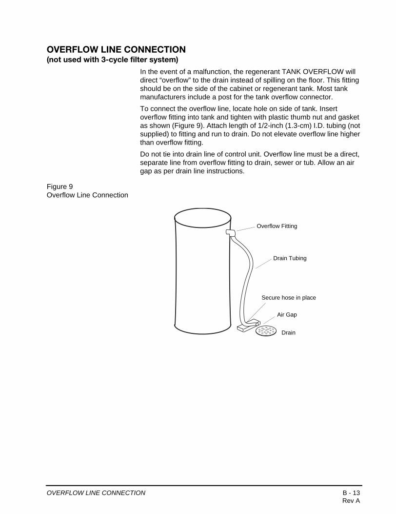
OVERFLOW LINE CONNECTION (not used with 3-cycle filter system)
In the event of a malfunction, the regenerant TANK OVERFLOW will direct “overflow” to the drain instead of spilling on the floor. This fitting should be on the side of the cabinet or regenerant tank. Most tank manufacturers include a post for the tank overflow connector.
To connect the overflow line, locate hole on side of tank. Insert overflow fitting into tank and tighten with plastic thumb nut and gasket as shown (Figure 9). Attach length of 1/2-inch (1.3-cm) I.D. tubing (not supplied) to fitting and run to drain. Do not elevate overflow line higher than overflow fitting.
Do not tie into drain line of control unit. Overflow line must be a direct, separate line from overflow fitting to drain, sewer or tub. Allow an air gap as per drain line instructions.
Figure 9Overflow Line Connection
Overflow Fitting
Drain Tubing
Air Gap
Drain
Secure hose in place
OVERFLOW LINE CONNECTION B - 13Rev A

REGENERANT LINE CONNECTION (not used with 3-cycle filter system)
The regenerant line from the tank connects to the valve. Make the connections and hand tighten. Be sure that the regenerant line is secure and free from air leaks. Even a small leak may cause the regenerant line to drain out, and the conditioner will not draw regenerant from the tank. This may also introduce air into the valve causing problems with valve operation.
Most installations utilize a tank check valve. This is not necessary when using the 255 valve with the built-in aircheck. Using a tank check valve with the 255 valve with aircheck will result in premature checking of the aircheck valve, before the tank is empty.
Figure 10AAir Check for 255 valve
Regenerant Line Connection
Regenerant Line Connection
NOTE: When installing a 3-cycle filter (253, 263, or 273 valve) use a cap on the regenerant line connection to prevent water seepage from the port. See Parts section (Section F) for part number.
Figure 10BPerforma Valve
B - 14 Rev A

CAMSHAFTThe front end of the camshaft has an indicator cup. The cup has slots in the outer periphery and numbers on the inside face (Figure 12).
The numbers can be seen with the cover off, from the front over the top of the controller. The number at the top indicates which regeneration cycle is currently in progress.
Figure 12Camshaft Front End for 255, 263, and 268 valve bodies
The corresponding slot for the number is positioned at the optical sensor which is approximately 90 degrees out of phase.
Regeneration Cycle Indicators
C0 = Treated Water - normal operation modeC1 = Backwash CycleC2 = Regenerant Draw Cycle (not used in filter mode)C3 = Slow Rinse Cycle (not used in filter mode)C4 = System PauseC5 = Fast Rinse Cycle 1C6 = Backwash Cycle 2 (not used in filter mode)C7 = Fast Rinse Cycle 2 (not used in filter mode)C8 = Regenerant Refill (not used in filter mode)
Treated Water Slot
Treated Water Indicator(normal operation)
CAMSHAFT B - 17Rev A
DISINFECTION OF WATER CONDITIONERSThe materials of construction of the modern water conditioner will not support bacterial growth, nor will these materials contaminate a water supply. During normal use, a conditioner may become fouled with organic matter, or in some cases with bacteria from the water supply. This may result in an off-taste or odor in the water.
Some conditioners may need to be disinfected after installation and some conditioners will require periodic disinfection during their normal life.
Depending upon the conditions of use, the style of conditioner, the type of ion exchanger, and the disinfectant available, a choice can be made among the following methods.
Sodium or Calcium HypochloriteApplicationThese materials are satisfactory for use with polystyrene resins, synthetic gel zeolite, greensand and bentonites.
5.25% Sodium HypochloriteThese solutions are available under trade names such as Clorox*. If stronger solutions are used, such as those sold for commercial laundries, adjust the dosage accordingly.
1. Dosage
A. Polystyrene resin; 1.2 fluid ounce (35.5 ml) per cubic foot.
B. Non-resinous exchangers; 0.8 fluid ounce (23.7 ml) per cubic foot.
2. Brine tank conditioners
A. Backwash the conditioner and add the required amount of hypochlorite solution to the well of the regenerant tank. The regenerant tank should have water in it to permit the solution to be carried into the conditioner.
B. Proceed with the normal regeneration.
*Clorox is a trademark of the Clorox Company.
C - 2 DISINFECTION OF WATER CONDITIONERS Rev A

Calcium HypochloriteCalcium hypochlorite, 70% available chlorine, is available in several forms including tablets and granules. These solid materials may be used directly without dissolving before use.
1. Dosage
A. Two grains (approximately 0.1 ounce [3 ml] ) per cubic foot.
2. Regenerant tank conditioners
A. Backwash the conditioner and add the required amount of hypochlorite to the well of the regenerant tank. The regenerant tank should have water in it to permit the chlorine solution to be carried into the conditioner.
B. Proceed with the normal regeneration.
DISINFECTION OF WATER CONDITIONERS C - 3Rev A

700 SERIES CONTROLLER
Power Loss Memory Retention
The Logix series controllers feature battery-free time and date retention during the loss of power. This is designed to last a minimum of 8 hours depending on the installation. The controller will continue to keep time and day in dynamic memory while there is no AC power.
The controller will not track water usage on volumetric demand controls in the event of a power failure.
All programmed parameters are stored in the Logix series static memory and will not be lost in the event of a power failure. These settings are maintained separately from the time and day settings.
Motor
The Logix series controller uses a standard 12-volt AC motor that works with either 50 Hz or 60 Hz. The same motor is used worldwide and does not need to be changed for different power conditions.
Power
Logix Series controllers are available in two power configurations:
1. The North American model requires 60 Hz input. The controller will display USA units when power is first applied.
2. The World model accepts either 60 or 50 Hz input and will automatically adjust measurement units when power is first applied.
D - 2 700 SERIES CONTROLLERRev A

Information entered or calculated by the controller is stored in two different ways.
A static memory will store:
Media volumeRegenerant setting Time of regenerationDays between regeneration Filter mode
A dynamic memory with 8 hour retention will store:
Current day of weekRunning clock
Variable Reserve Function
The Logix metered-demand volumetric controllers (760 and 762) are designed to have a variable reserve feature. This feature automatically adjusts the reserve to the end-user’s water usage schedule.
A variable reserve saves salt and water by only regenerating when absolutely necessary, and ensures enough soft water for typical high-water usage days.
Each day of regeneration the controller reviews the last four weeks of water usage for the same day of the week to determine if the remaining capacity is adequate for the next day of the week. If not, it will initiate an automatic regeneration.
NOTE: Water flow to the valve can be turned on or bypassed when the controller is powered up for the first time.
700 SERIES CONTROLLER D - 3Rev A

DISPLAY ICONS 700 CONTROLLER
Figure 1
1. Days of the week. The flag immediately below the day will appear when that day has been programmed as a day the system should regenerate (used with 7-day timer programming).
2. See #3
3. This cursor is displayed when the days between regeneration are being programmed (used with .5 to 99 day regeneration programming).
4. One of these cursors will be displayed to indicate which day will be programmed into the controller.
5. "PM" indicates that the time displayed is between 12:00 noon and 12:00 midnight (there is no AM indicator). PM indicator is not used if clock mode is set to 24-hour.
6. When "MIN" is displayed, the value entered is in minute increments.
7. When "LBS" is displayed, the value entered is in pounds.
8. When "Kg" is displayed, the value entered is in kilograms or kilograins.
9. Four digits used to display the time or program value. Also used for error codes.
10. Colon flashes as part of the time display. Indicates normal operation.
LBS
PMMIN
KGx2
Time & Day
Regen Time & Day
Salt
SU MO TU WE TH FR SA DAYS
x100PHCCapacity
Hardness
1 2
3
4
5
6
7
8
9
1011
1213
14
1516
17 18
1920
212223242526
27
28
NOTE: In normal operation and during programming, only a few of the icons will actually be displayed.
D - 4 DISPLAY ICONS 700 CONTROLLERRev A
11. Locked/unlocked indicator. In Level I programming this is displayed when the current parameter is locked-out. It is also used in Level II programming to indicate if the displayed parameter will be locked (icon will flash) when controller is in Level I.
12. When "x2" is displayed, a second regeneration has been called for.
13. The recycle sign is displayed (flashing) when a regeneration at the next time of regeneration has been called for. Also displayed (continuous) when in regeneration.
14. The display cursor is next to "SALT" when programming the amount of regenerant. If the controller is on a 3-cycle filter then backwash time is programmed.
15. The display cursor is next to "REGEN TIME & DAY" when programming the time of regeneration and the days of regeneration.
16. The display cursor is next to "TIME & DAY" when programming the current time and day.
17. The hourglass is displayed when the motor is running. The camshaft should be turning.
18. These cursors will appear next to the item that is currently displayed.
19. X100 multiplier for large values.
20. Not used.
21. Shows when water is flowing through the valve.
22. Maintenance interval display—not used on 740/760 controllers.
23. Used with #24, #25, and #26. Displays a sequence number or a value.
24. History Values. The number displayed by #23 identifies which history value is currently displayed.
25. Parameter. Displayed only in Level II Programming. The number displayed by #23 identifies which parameter is currently displayed.
26. Cycle. The number displayed by #23 is the current cycle in the regeneration sequence.
27. Hardness setting—only used with 760 and 762 controllers.
28. Capacity display—shows estimated system capacity.
DISPLAY ICONS 700 CONTROLLER D - 5Rev A

KEYPAD — Buttons
1. DOWN arrow. Generally used to scroll down or increment through a group of choices.
2. SET. Used to accept a setting that normally becomes stored in memory. Also used together with the arrow buttons.
3. UP arrow. Generally used to scroll up or increment through a group of choices.
4. Regenerate. Used to command the controller to regenerate. Also used to change the lock mode.
Programming Conventions
The 700 series controller is programmed using the buttons on the keypad. The programming instructions will be described two ways whenever a section has keypad input.
First, a table shows simplified instructions. Second, text follows that describes the action. In each table:
"Action" lists the event or action desired.
"Keys" are listed as:
UP for up arrowDOWN for down arrowSET for setREGEN for regeneration
"Duration" describes how long a button is held down:
P/R for press and releaseHOLD for press and holdX sec for a number of seconds to press the button and hold it down
"Display" calls out the display icons that are visible.
21 3 4
D - 6 KEYPAD — ButtonsRev A
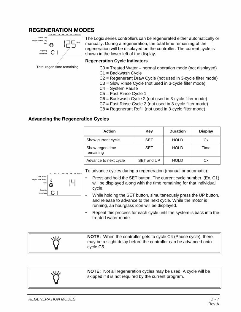
REGENERATION MODESThe Logix series controllers can be regenerated either automatically or manually. During a regeneration, the total time remaining of the regeneration will be displayed on the controller. The current cycle is shown in the lower left of the display.
Regeneration Cycle IndicatorsC0 = Treated Water – normal operation mode (not displayed)C1 = Backwash CycleC2 = Regenerant Draw Cycle (not used in 3-cycle filter mode)C3 = Slow Rinse Cycle (not used in 3-cycle filter mode)C4 = System PauseC5 = Fast Rinse Cycle 1C6 = Backwash Cycle 2 (not used in 3-cycle filter mode)C7 = Fast Rinse Cycle 2 (not used in 3-cycle filter mode)C8 = Regenerant Refill (not used in 3-cycle filter mode)
Advancing the Regeneration Cycles
To advance cycles during a regeneration (manual or automatic):
• Press and hold the SET button. The current cycle number, (Ex. C1) will be displayed along with the time remaining for that individual cycle.
• While holding the SET button, simultaneously press the UP button, and release to advance to the next cycle. While the motor is running, an hourglass icon will be displayed.
• Repeat this process for each cycle until the system is back into the treated water mode.
Time & Day
Regen Time & Day
Salt
SU MO TU WE TH FR SA DAYS
CCapacity
Hardness
MIN
Total regen time remaining
Action Key Duration Display
Show current cycle SET HOLD Cx
Show regen time remaining
SET HOLD Time
Advance to next cycle SET and UP HOLD Cx
Time & Day
Regen Time & Day
Salt
SU MO TU WE TH FR SA DAYS
CCapacity
Hardness
NOTE: When the controller gets to cycle C4 (Pause cycle), there may be a slight delay before the controller can be advanced onto cycle C5.
NOTE: Not all regeneration cycles may be used. A cycle will be skipped if it is not required by the current program.
REGENERATION MODES D - 7Rev A

Cancelling a Regeneration
To cancel a regeneration (either manual or automatic):
• Press the SET key and UP buttons simultaneously and hold until the hourglass icon starts flashing (approximately 5 seconds).
• The regeneration is cancelled.
• The camshaft rotates to the treated water position (may take up to 2 min.)
• Hourglass flashes while motor runs.
If a second regeneration was programmed (display shows a 2X by the regeneration icon) both regenerations must be cancelled separately.
Action Key Duration Display
Cancel regen SET and UP 5 sec. Hourglass starts to flash
WARNING: Cancelling a regeneration may cause undesirable or salty water to go into the plumbing. Only use this function when absolutely necessary.
WARNING: If the regeneration cycle is cancelled after the regenerant draw cycle (C2), check the water level in the regenerant tank. It must be refilled to the proper level.
D - 8 REGENERATION MODESRev A

Manual Regenerations
The controller can be manually instructed to perform a regeneration.
There are two choices: The controller will perform a delayed regeneration at the next time of regeneration (ex: 2:00 AM that night), or regenerate immediately.
For a delayed regeneration (at the next set time of regeneration):
• Push the REGEN button once. The recycle symbol will be flashing on the display. Push the REGEN button again to cancel.
For an immediate regeneration:
• Push and hold the REGEN button for five seconds. The display will show the regeneration symbol. The camshaft will start rotating to cycle C1.
For an immediate, double regeneration:
• After an immediate manual regeneration has begun, and the camshaft has rotated to cycle C1, you can initiate a second immediate manual regeneration.
• Press and hold the REGEN button for 5 seconds once the camshaft has begun cycle C1.
• The display will show a x2 icon indicating that a second manual regeneration will occur after the current regeneration is completed.
Action Key Duration Display
Regen at next time of regen
REGEN P/R Recycle icon flashes
Cancel regen REGEN P/R when recycle icon is flashing
Recycle icon disappears
Immediate regen
REGEN 5 sec. Recycle icon appears
Immediate double regen
REGEN 5 sec when immediate manual regen has
started
X2 icon appears
PM
Time & Day
Regen Time & Day
Salt
SU MO TU WE TH FR SA DAYS
Icon Flashing
CCapacity
Hardness
x2
Time & Day
Regen Time & Day
Salt
SU MO TU WE TH FR SA DAYS
CCapacity
Hardness
Second Regeneration Scheduled
REGENERATION MODES D - 9Rev A
700 SERIES INITIAL POWER-UP
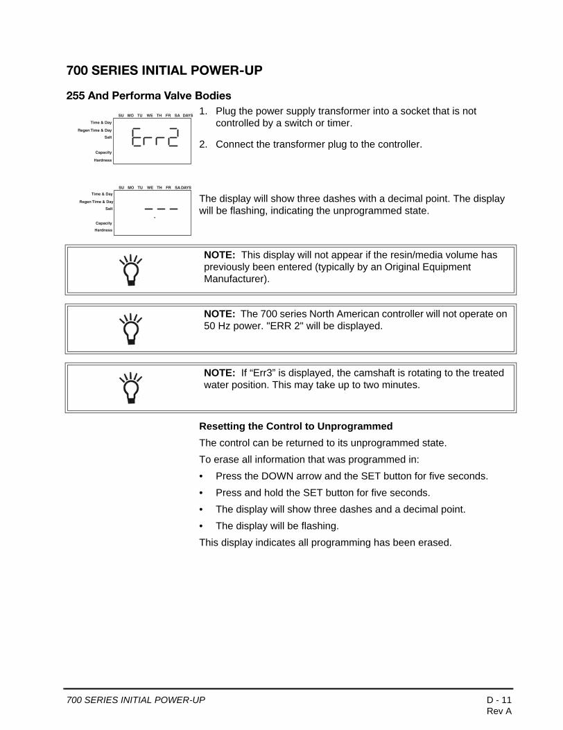
255 And Performa Valve Bodies1. Plug the power supply transformer into a socket that is not
controlled by a switch or timer.
2. Connect the transformer plug to the controller.
The display will show three dashes with a decimal point. The display will be flashing, indicating the unprogrammed state.
Resetting the Control to UnprogrammedThe control can be returned to its unprogrammed state.
To erase all information that was programmed in:
• Press the DOWN arrow and the SET button for five seconds.
• Press and hold the SET button for five seconds.
• The display will show three dashes and a decimal point.
• The display will be flashing.
This display indicates all programming has been erased.
Time & Day
Regen Time & Day
Salt
Capacity
Hardness
SU MO TU WE TH FR SA DAYS
Time & Day
Regen Time & Day
Salt
SU MO TU WE TH FR SA DAYS
Capacity
Hardness
NOTE: This display will not appear if the resin/media volume has previously been entered (typically by an Original Equipment Manufacturer).
NOTE: The 700 series North American controller will not operate on 50 Hz power. "ERR 2" will be displayed.
NOTE: If “Err3” is displayed, the camshaft is rotating to the treated water position. This may take up to two minutes.
700 SERIES INITIAL POWER-UP D - 11Rev A

Enter Resin/Media Volume or Select Filter Operation
The first time that the controller is powered-up, the system type and size will need to be entered, by programming in the volume of resin/media for the conditioner in cubic feet (liters) or selecting the 3-cycle filter option. This resin/media volume setting is used for determining the default settings for the controller.
The system is programmed in pre-defined increments. Choose the resin/media volume closest to the actual volume of the resin/media tank.
3. Use the UP and DOWN arrows to scroll through the preset resin/media volumes. If you do not know the volume of the system, contact the system supplier.
If your exact resin/media volume is not displayed, choose the setting closest to the resin/media volume in the tank.
4. When the volume that matches your tank is displayed, press SET. The number is stored in the controller.
Action Key Duration Display
Choose media volume
UP or DOWN arrow
P/R Preprogrammed volumes
Select volume SET P/R Selected Volume
Time & Day
Regen Time & Day
Salt
SU MO TU WE TH FR SA DAYS
Capacity
Hardness
Time & Day
Regen Time & Day
Salt
SU MO TU WE TH FR SA DAYS
Capacity
Hardness
3-cycle filter
NOTE: To change to a filter, scrolling to 0 will indicate "F", for a 3-cycle filter operation. This tells the controller to no longer act as a 7-cycle conditioner, but rather as a 3-cycle filter. In filter mode, the regenerant draw/slow rinse, and refill cycles are skipped in the regeneration sequence.
NOTE: Verify that the resin/media volume selected is correct. An incorrect volume will significantly affect performance of the conditioner, because the controller will be using inaccurate settings for the actual size of the system.
NOTE: The resin/media volume is stored in memory that is not affected by power loss.
WARNING: The resin/media volume is used to control the regeneration cycle. This setting can be changed by entering into the history menu. See History Values Programming Section.
D - 12 700 SERIES INITIAL POWER-UPRev A

Setting the Time of Day
After the resin/media volume has been programmed, the time of day will need to be entered. The display will flash 12:00, along with the cursor next to Time of Day.
5. The UP and DOWN arrows are used to set the time of day. When the correct time is displayed, push SET.
Setting the Day of the Week
The display will show a small cursor at the top of the display. Push SET to enter the programming mode. The cursor is moved with the arrow buttons to a position below the day of the week.
6. Use the arrow buttons to move the cursor below the current day of the week, hit SET to enter the day.
Action Key Duration Display
Display Correct Time
UP or DOWN arrow
P/R Increments time
Select time SET P/R Selected time
Time & Day
SU MO TU WE TH FR SA DAYS
Capacity
Hardness
NOTE: Push and hold the arrow button to quickly scroll through the time. PM is displayed next to the time (12-hour mode). AM is not designated.
Action Key Duration Display
Enter programming mode
SET P/R Cursor flashes below one of the
days
Move to current day
UP or DOWN arrows
P/R Flashing cursor moves
Select day SET P/R Cursor steady below selected
day
Time & Day
Regen Time & Day
Salt
SU MO TU WE TH FR SA DAYS
Capacity
Hardness
NOTE: The time of day and day of week are stored in a temporary (dynamic) memory. If power to the controller is lost, the running clock and day are maintained for at least 8 hours.
700 SERIES INITIAL POWER-UP D - 13Rev A
The system is now ready to operate.
The controller will default to regenerating every three days (on 740 controller or volumetrically on 760 controller), and to a standard salt (9 pounds per cubic foot of resin/media) setting. When programming in metric the standard salt setting will be 120 g/L.
If these settings are acceptable for the application, proceed on to Placing the Conditioner into Operation.
If the application requires additional refinement of the controller features (including regeneration frequency and salting amount), then see Level II Programming (Section E) for further instructions.
D - 14 700 SERIES INITIAL POWER-UPRev A

PLACING CONDITIONER INTO OPERATION
Conditioner Start-Up
After you have performed the previous initial power-up steps, you will need to place the conditioner into operation. Follow these steps carefully, as they differ from previous Autotrol valve instructions.
1. Remove the cover from the valve. Removing the cover will allow you to see that the camshaft is turning, and in which cycle the camshaft is currently positioned.
2. With the supply water for the system still turned off, position the bypass valve to the “not in bypass” (normal operation) position.
3. Hold the REGEN button on the controller down for 5 seconds. This will initiate a manual regeneration.
The controller will indicate that the motor is turning the camshaft to the cycle C1 (Backwash) position by flashing an hourglass. The controller will display the total regen time remaining.
If you press and hold the SET button, the controller will indicate the time remaining in the current cycle.
4. Fill the media tank with water.
A. While the controller is in cycle C1 (Backwash), open the water supply valve very slowly to approximately the 1/4 open position.
B. When all of the air has been purged from the media tank (water begins to flow steadily from the drainline), open the main supply valve all of the way. This will purge the final air from the tank.
C. Allow water to run to drain until the water runs clear from the drain line. This purges any refuse from the media bed.
NOTE: The control valve can be started-up even if power is not yet available to the controller. The valve must be connected to water supply. The motor can be unmounted from the valve, and the camshaft can be indexed manually counterclockwise by hand. This will allow the tank to be filled and allows regenerant draw to be tested. See Motor Removal in Maintenance And Service (Section F) of this manual for further instructions.
Time & Day
Regen Time & Day
Salt
SU MO TU WE TH FR SA DAYS
CCapacity
Hardness
Flashing
WARNING: If opened too rapidly or too far, media may be lost out of the tank into the valve or the plumbing. In the 1/4 open position, you should hear air slowly escaping from the valve drain line.
PLACING CONDITIONER INTO OPERATION D - 15Rev A

D. Turn off the water supply and let the system stand for about five minutes. This will allow for any air trapped to escape from the tank.
5. Add water to the regenerant tank (initial fill) (conditioner only).
A. With a bucket or hose, add approximately 4 gallons (15 liters) of water to the regenerant tank.
If the tank has a salt platform in the bottom of the tank, add water until the water level is approximately 1 inch (25 mm) above the platform.
6. Engage the refill cycle to prime the line between the regenerant tank and the valve (conditioner only).
A. Slowly open the main water supply valve again, to the fully open position. Be sure not to open too rapidly as that would push the media out of the media tank.
B. Advance the controller to the Refill Position. From cycle C1 (Backwash), press and hold the SET button. This will display the current cycle.
While pressing the SET button, press the UP arrow to advance to the next cycle. Continue to advance through each cycle until you have reached cycle C8 (Refill).
NOTE: We recommend that you do not put regenerant into the tank until after the control valve has been put into operation. With no regenerant in the tank, it is much easier to view water flow and motion in the tank.
Action Key Duration Display
Display current cycle
SET 5 Sec Current cycle
Advance to next cycle
SET and UP P/R Next cycle
Advance to CO SET and UP 5 Sec CO
NOTE: As you advance through each cycle there will be a slight delay before you can advance to the next cycle. The hourglass icon will light while the camshaft is indexing. There may be a pause at cycle C4 (System Pause). This cycle allows the water/air pressure to equalize on each side of the valve discs before moving on. The hourglass will not be visible indicating that the system is paused.
D - 16 PLACING CONDITIONER INTO OPERATIONRev A

C. With the water supply completely open, when you arrive at cycle C8 (Refill), the controller will direct water down through the line to the regenerant tank. Let the water flow through the line until all air bubbles have been purged from the line.
D. Do not let the water flow down the line to the tank for more than one to two minutes, or the tank may overfill.
E. Once the air is purged from the line, press the SET button and the UP button simultaneously to advance to cycle C0 (Treated Water) position.
7. Draw water from the regenerant tank.
A. From the treated water position (cycle C0), advance the valve to the draw regenerant position. Hold the REGEN button down for five seconds.
The controller will begin a manual regen, and advance the control valve to the cycle C1 (Backwash). Press the SET and UP button to advance to cycle C2 (Draw).
B. With the controller in this position, check to see that the water in the regenerant tank is being drawn out of the tank. The water level in the tank should recede very slowly.
C. Observe the water being drawn from the regenerant tank for at least three minutes. If the water level does not recede, or goes up, reference the Troubleshooting section.
8. If the water level is receding from the regenerant tank you can then advance the controller back to the treated water (C0) position by pressing SET and the UP buttons simultaneously to advance the controller to the C0 position.
9. Finally, turn on a faucet plumbed after the water conditioner. Run the faucet until the water runs clear.
Action Key Duration Display
Advance to C1 REGEN 5 Sec REGEN icon steady, C1 and time remaining
Advance to C2 SET and UP P/R Regen icon steady, C2 and time remaining
Time & Day
Regen Time & Day
Salt
SU MO TU WE TH FR SA DAYS
CCapacity
Hardness
PLACING CONDITIONER INTO OPERATION D - 17Rev A

Things You Might Need to Know
• When the controller is first plugged in, it may display a flashing hourglass and the message Err 3, this means that the controller is rotating to the home position. If the Err 2 is displayed, check that the incoming power frequency matches the controller. The North American controller will not run with 50 Hz input. See the Troubleshooting section of this manual.
• The preset default time of regeneration is 2:00 AM. If you want to change it, see the Level II Programming section.
• English or Metric? The World controller senses the electrical input and decides which is needed. The North American controller only runs on 60 Hz and defaults to English units. To make changes see the Level II Programming section regarding that particular item.
• The 740/760 controller can be programmed to regenerate on specific days of the week. See Level II Programming section.
• If electrical power is not available, the camshaft can be rotated counterclockwise by hand if the motor is removed. See Motor Removal in the Maintenance section.
• The 700 Logix series controllers send commands to the motor for camshaft movement. However, water pressure/flow are required during the regeneration cycle for backwash, purge and refill, and brine draw to actually take place.
• Make sure control power source is plugged in. The transformer should be connected to a non-switched power source.
• You can start programming at the beginning by resetting the amount of media. When viewing H0 (History Value) push and hold SET for five seconds. The display reverts back to --- and any programmed information is lost. Return to 700 Series Initial Power Up.
Time & Day
Regen Time & Day
Salt
Capacity
Hardness
SU MO TU WE TH FR SA DAYS
D - 18 PLACING CONDITIONER INTO OPERATIONRev A

700 SERIES PROGRAMMINGThe Logix 700 Series controllers are designed to operate by only setting the time of day and the day of the week. The remaining settings have been set at the factory. These default settings will work for most applications.
The controller menu has three levels:
Level I Basic - This level is easily accessed by the user. The settings can be changed and saved as long as they are not locked.
Level II Professional - This level allows the installer to lock settings. The locked settings are viewable in the basic level but cannot be changed.
History Level - The operation history and the program are viewable. This information is used to troubleshoot and maintain the system.
E - 2 700 SERIES PROGRAMMINGRev A
760 BASIC PROGRAMMING
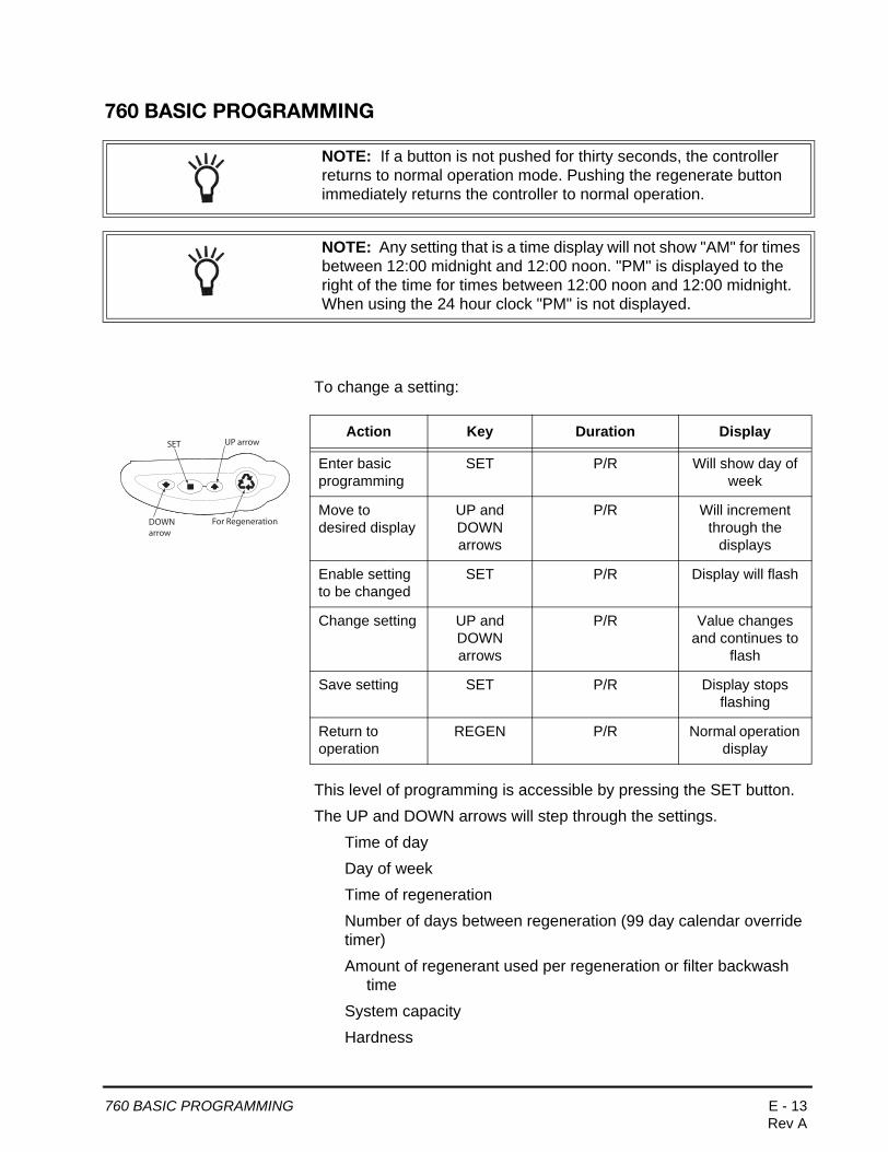
To change a setting:
This level of programming is accessible by pressing the SET button.
The UP and DOWN arrows will step through the settings.
Time of day
Day of week
Time of regeneration
Number of days between regeneration (99 day calendar override timer)
Amount of regenerant used per regeneration or filter backwash time
System capacity
Hardness
NOTE: If a button is not pushed for thirty seconds, the controller returns to normal operation mode. Pushing the regenerate button immediately returns the controller to normal operation.
NOTE: Any setting that is a time display will not show "AM" for times between 12:00 midnight and 12:00 noon. "PM" is displayed to the right of the time for times between 12:00 noon and 12:00 midnight. When using the 24 hour clock "PM" is not displayed.
Action Key Duration Display
Enter basic programming
SET P/R Will show day of week
Move to desired display
UP and DOWN arrows
P/R Will increment through the
displays
Enable setting to be changed
SET P/R Display will flash
Change setting UP and DOWN arrows
P/R Value changes and continues to
flash
Save setting SET P/R Display stops flashing
Return to operation
REGEN P/R Normal operation display
For Regeneration
SET UP arrow
DOWNarrow
760 BASIC PROGRAMMING E - 13Rev A

To make changes:
• Time of dayWhen the Time of Day is displayed, push SET. The time will flash. Use the arrow buttons to increase/decrease the time. Push SET to enter the selection.
• Day of the weekThe day of the week does not have a default setting. It is entered at Power-up. To change the current day, push SET when day of week is displayed. A flag will flash beneath the current day. Use the arrow buttons to change. Push SET to enter the selection.
• Time of regenerationThis is set for 2:00 AM as the default. The controller does not account for daylight savings time.
To change this setting, push SET. Use the arrow buttons to increase/decrease the time. Push SET to enter the selection.
• Calendar overrideThe controller can be programmed to regenerate automatically from a 1/2 (.5) day to a 99 day frequency.
The 1/2 day regeneration mode will regenerate at the "time of regeneration", as well as 12 hours opposite from that time. For example, the controller will regenerate at 2 AM and at 2 PM on the same day.
The default setting is 14 days. To change, push SET when this setting is displayed. Use the arrow buttons to increase/decrease. Push SET to enter the selection.
Time & Day
SU MO TU WE TH FR SA DAYS
Capacity
Hardness
Time & Day
Regen Time & Day
Salt
SU MO TU WE TH FR SA DAYS
Capacity
Hardness
Time & Day
Regen Time & Day
Salt
SU MO TU WE TH FR SA DAYS
Capacity
Hardness
Time & Day
Regen Time & Day
Salt
SU MO TU WE TH FR SA DAYS
Capacity
Hardness
WARNING: Setting days between regeneration to zero will cause the system to not regenerate. This setting is used for selecting regeneration on specific days or to use with a remote regeneration input. See below.
NOTE: Regeneration on specific day is used to provide regeneration when water demands are not steady. Example: If the weekdays have low usage and the weekend is high, then regeneration every three days will not meet the requirements.
E - 14 760 BASIC PROGRAMMINGRev A

If the installation is a 3-cycle filter, skip to Filter Backwash Time. Amount of backwash does not apply.
• Amount of regenerant used per regenerationThe Logix series controllers are set-up to automatically calculate the capacity of the system by multiplying the resin/media volume that was entered earlier into the controller, with the regenerant amount entered by the dealer/installer. This eliminates the need for salting efficiency tables.
The default setting is S (Standard Salt).
To enable the most simple programming possible on the 760 controllers, the dealer/installer has three salt amount options to choose from. These are set up to give the installation the maximum performance based on the inputs by the dealer/installer. The three salting options are:
High Salt - This setting gives the installation the highest capacity possible for that resin volume. This is a great setting for applications with very high hardness, many occupants or for applications where the dealer wants to always ensure that the application has soft water. This setting may tend to use less water over the course of a year, because it generally needs to be regenerated less often. This setting is displayed as an "H".
Standard Salt - This is the default setting for the controller. This setting fits most applications around the world. It gives you an efficient use of salt, while maintaining a large enough capacity to regenerate every three days for most applications. This setting is displayed as an "S".
Low Salt - This setting is provided to give your installation the maximum efficiency of salt usage, as measured in grains of hardness softened per pound of salt used (grams of CaCO3 removed per kilogram of salt used). This setting is useful for markets where highly efficient conditioners are expected or required by the consumers or law. This setting is displayed as an "L".
Time & Day
Regen Time & Day
Salt
SU MO TU WE TH FR SA DAYS
Capacity
Hardness
Time & Day
Regen Time & Day
Salt
SU MO TU WE TH FR SA DAYS
Capacity
Hardness
Time & Day
Regen Time & Day
Salt
SU MO TU WE TH FR SA DAYS
Capacity
Hardness
Time & Day
Regen Time & Day
Salt
SU MO TU WE TH FR SA DAYS
Capacity
Hardness
760 BASIC PROGRAMMING E - 15Rev A
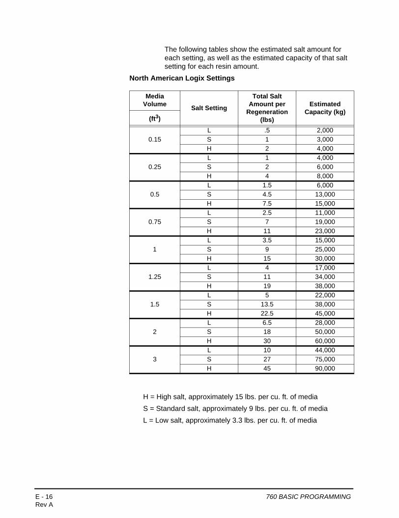
The following tables show the estimated salt amount for each setting, as well as the estimated capacity of that salt setting for each resin amount.
North American Logix Settings
H = High salt, approximately 15 lbs. per cu. ft. of media
S = Standard salt, approximately 9 lbs. per cu. ft. of media
L = Low salt, approximately 3.3 lbs. per cu. ft. of media
Media Volume Salt Setting
Total Salt Amount per
Regeneration (lbs)
Estimated Capacity (kg)
(ft3)
0.15L .5 2,000S 1 3,000H 2 4,000
0.25L 1 4,000S 2 6,000H 4 8,000
0.5L 1.5 6,000S 4.5 13,000H 7.5 15,000
0.75L 2.5 11,000S 7 19,000H 11 23,000
1L 3.5 15,000S 9 25,000H 15 30,000
1.25L 4 17,000S 11 34,000H 19 38,000
1.5L 5 22,000S 13.5 38,000H 22.5 45,000
2L 6.5 28,000S 18 50,000H 30 60,000
3L 10 44,000S 27 75,000H 45 90,000
E - 16 760 BASIC PROGRAMMINGRev A

To program the salt amount, press the SET button to enter the change mode. The S default will begin to flash. Use the UP and DOWN arrow keys to scroll through the three settings. Press the SET button to enter the amount.
• Filter backwash time - when filter setting is chosenIf the system is set up as a 3-cycle filter, regenerant amount is unnecessary. The controller deactivates the regenerant amount setting, and changes to an adjustable backwash time in minutes.
Press SET to change the time. The default time of 14 minutes will begin to flash. Use the UP and DOWN arrows to select the appropriate backwash time for the media type and amount used. The controller can use 0 to 99 minutes for backwash. Press SET again to enter that time.
If using this controller as a filter, an alternate 760F faceplate overlay label is available that has the text “backwash time” instead of “salt” printed. See the Spare Parts section for the part number for this overlay label.
• CapacityThe 760 controller is designed to estimate capacity of the system by multiplying the initial resin/media volume by the regenerant amount programmed in under "Amount of regenerant used per regeneration”.
An estimated total system capacity is displayed in kilograins (kilograms CaCO3) that can be removed by the fully regenerated media bed. This value is derived by standard water treatment industry norms. The system capacity is displayed merely for the installers reference when determining regeneration frequency.
Time & Day
Regen Time & Day
Backwash Time
SU MO TU WE TH FR SA DAYS
Capacity
Hardness
NOTE: If the controller was incorrectly set as a conditioner instead of a filter, press the DOWN button and SET button for five seconds to display resin volume. Press and hold the SET button for five seconds to reset the resin volume to ---. Use the ARROW buttons to increment the display to F. Press SET.
KG
Time & Day
Regen Time & Day
Salt
SU MO TU WE TH FR SA DAYS
Capacity
Hardness
NOTE: Capacity is the result of the amount of media and the tank and the salt setting. The default capacity will be changed by selecting a different regenerant setting.
E - 18 760 BASIC PROGRAMMINGRev A

• Hardness settingThe hardness setting is set in grains per gallon (ppm CaCO3). The hardness is divided into the total capacity setting, giving a total volume of water that can be conditioned before a regeneration is needed. To set, press SET when P8 is displayed, and use the UP or DOWN buttons to increment. Press SET again to accept the setting.
760 BASIC PROGRAMMING E - 19Rev A

760 PROFESSIONAL PROGRAMMING
In this level all of the programming features of basic programming are available. In addition, the settings can be locked/unlocked.
A setting that is locked will display a lock icon when viewed in the basic level.
A locked setting is viewable in the basic programming menus but it cannot be changed.
When viewing a setting in this level the display will show a "P" value. This corresponds to the displayed setting.
Level II menus include:
P1 = Time of day
P2 = Day of week
P3 = Time of regeneration
P4 = Number of days between regeneration
P5 = Not used
P6 = Amount of regenerant used per regeneration or filter backwash time
P7 = System capacity
P8 = Hardness
P9 = Units of measure
P10=Clock mode
NOTE: If a button is not pushed for thirty seconds the controller returns to normal operation mode. Pushing the UP and DOWN arrows for 5 seconds returns the controller to normal operation.
NOTE: Any setting that is a time display will not show "AM" for times between 12:00 midnight and 12:00 noon. "PM" is displayed to the right of the time for times between 12:00 noon and 12:00 midnight. When using the 24 hour clock :"PM" is not displayed.
Time & Day
Regen Time & Day
Salt
SU MO TU WE TH FR SA DAYS
PCapacity
Hardness
P Value
E - 20 760 PROFESSIONAL PROGRAMMINGRev A

To enter Level II (Professional Programming) and change a setting:
English/Metric - P9 (Only accessed in Professional Level)This setting is entered automatically at first power-up. The North American controller will default to English units. The World controller senses the electrical input and determines English or metric units. 0 is English units, 1 is metric units. Use the arrow buttons to change this setting. Press SET to accept the setting.
12 hour clock/24 hour clock - P10 (Only accessed in Professional Level)This setting is entered automatically at first power-up. The North American controller will default to English units. The World controller senses the electrical input and determines a 12 or 24 hour clock. 0 is 12-hour clock. 1 is 24-hour clock. Use the arrow buttons to change this setting. Press SET to accept the setting.
Action Key Duration Display
Enter Level IIprogramming
UP and DOWN
5 Sec. P1 display
Return to operation
UP and DOWN
5 Sec. Time and day of week
Increment through menus
UP and DOWN
P/R Next parameter display
Enable setting to be changed
SET P/R Parameter will flash
Change value UP and DOWN
P/R Value changes
Save setting SET P/R Records value and next
parameter is displayed
For Regeneration
SET UP arrow
DOWNarrow
Time & Day
Regen Time & Day
Salt
SU MO TU WE TH FR SA DAYS
PCapacity
Hardness
Time & Day
Regen Time & Day
Salt
SU MO TU WE TH FR SA DAYS
PCapacity
Hardness
NOTE: Once SET is pressed in P10 the controller will change to treated water (normal operation) mode. The time of day is displayed and the colon is flashing.
760 PROFESSIONAL PROGRAMMING E - 21Rev A

To make changes:
• Lock On/OffSettings locked in the Professional Level can be viewed in the Basic Level but not changed. To change the lock status of the displayed setting, push the REGEN button. This toggles the lock icon on and off. If the lock is illuminated or flashing in Professional Level, the parameter will be locked in Basic Level programming.
Time & Day
Regen Time & Day
Salt
SU MO TU WE TH FR SA DAYS
Capacity
Hardness
P
E - 22 760 PROFESSIONAL PROGRAMMINGRev A
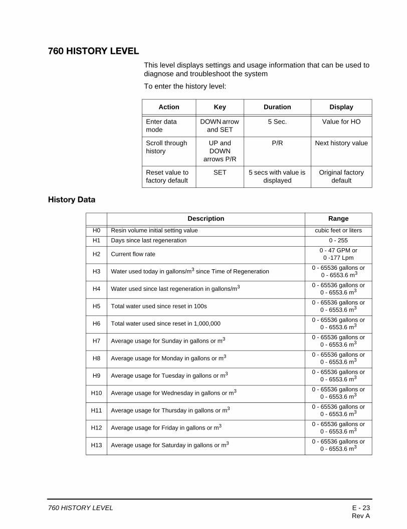
760 HISTORY LEVELThis level displays settings and usage information that can be used to diagnose and troubleshoot the system
To enter the history level:
History Data
Action Key Duration Display
Enter data mode
DOWN arrow and SET
5 Sec. Value for HO
Scroll through history
UP and DOWN
arrows P/R
P/R Next history value
Reset value to factory default
SET 5 secs with value is displayed
Original factory default
Description Range
H0 Resin volume initial setting value cubic feet or liters
H1 Days since last regeneration 0 - 255
H2 Current flow rate 0 - 47 GPM or 0 -177 Lpm
H3 Water used today in gallons/m3 since Time of Regeneration 0 - 65536 gallons or 0 - 6553.6 m3
H4 Water used since last regeneration in gallons/m3 0 - 65536 gallons or 0 - 6553.6 m3
H5 Total water used since reset in 100s 0 - 65536 gallons or 0 - 6553.6 m3
H6 Total water used since reset in 1,000,000 0 - 65536 gallons or 0 - 6553.6 m3
H7 Average usage for Sunday in gallons or m3 0 - 65536 gallons or 0 - 6553.6 m3
H8 Average usage for Monday in gallons or m3 0 - 65536 gallons or 0 - 6553.6 m3
H9 Average usage for Tuesday in gallons or m3 0 - 65536 gallons or 0 - 6553.6 m3
H10 Average usage for Wednesday in gallons or m3 0 - 65536 gallons or 0 - 6553.6 m3
H11 Average usage for Thursday in gallons or m3 0 - 65536 gallons or 0 - 6553.6 m3
H12 Average usage for Friday in gallons or m3 0 - 65536 gallons or 0 - 6553.6 m3
H13 Average usage for Saturday in gallons or m3 0 - 65536 gallons or 0 - 6553.6 m3
760 HISTORY LEVEL E - 23Rev A

When in history values mode a small "H” will be displayed in the lower left corner of the display. Next to the “H” will be the number that applies to the history value.
H0— System Resin Volume SettingThe Logix history value H0 displays the initial resin volume setting (programmed when the system was first set up.
If the value is incorrect and needs to be reset, press and hold the SET button for five seconds to reset the controller.
WARNING: Resetting the resin volume resets the entire controller back to the factory default. Only use if absolutely necessary. The control will need to be completely reprogrammed.
E - 24 760 HISTORY LEVELRev A

VALVE SERVICE
Cover
The cover provides protection for the controller, wiring, and other components. This cover will be removed for most service and maintenance.
When installed, the cover provides NEMA 3 water protection. This protects from falling water up to 30 degrees from vertical.
To remove cover:1. Grasp side edges toward rear of the valve.
2. Pull outwards until the slots in the cover clears the projections on the top plate.
3. Lift up on the rear and pull forward to clear the control module.
To install cover:1. Position cover to be low in front and under the bottom edge of the
control module.
2. The cover will hook on the bottom of the controller and drop down over the camshaft.
3. To finish, grasp the side edges and pull outward to clear the projections on the top plate.
4. Drop down until the cover snaps in place.
Electronic Control Module
The purpose of the electronic control module is to control the regeneration cycle. The control module has several variations. When replacing the controller, use the same model or some functions may not work. This is an electronic controller that is programmable and uses input/output signals.
To remove control module:1. Disconnect power to the unit.
2. Remove valve cover.
3. Press trip lever to release module from top plate.
4. Pivot the top forward and up.
5. Remove any wire connections. Wire connectors have a locking tab that must be squeezed before removing.
Slots
Trip Lever
NOTE: There is no need to label the wires. The keyed connectors will only plug back into one site.
F - 2 VALVE SERVICERev A
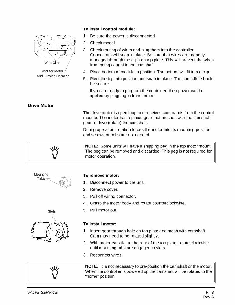
To install control module:1. Be sure the power is disconnected.
2. Check model.
3. Check routing of wires and plug them into the controller. Connectors will snap in place. Be sure that wires are properly managed through the clips on top plate. This will prevent the wires from being caught in the camshaft.
4. Place bottom of module in position. The bottom will fit into a clip.
5. Pivot the top into position and snap in place. The controller should be secure.
If you are ready to program the controller, then power can be applied by plugging in transformer.
Drive Motor
The drive motor is open loop and receives commands from the control module. The motor has a pinion gear that meshes with the camshaft gear to drive (rotate) the camshaft.
During operation, rotation forces the motor into its mounting position and screws or bolts are not needed.
To remove motor:1. Disconnect power to the unit.
2. Remove cover.
3. Pull off wiring connector.
4. Grasp the motor body and rotate counterclockwise.
5. Pull motor out.
To install motor:1. Insert gear through hole on top plate and mesh with camshaft.
Cam may need to be rotated slightly.
2. With motor ears flat to the rear of the top plate, rotate clockwise until mounting tabs are engaged in slots.
3. Reconnect wires.
Wire Clips
Slots for Motor and Turbine Harness
NOTE: Some units will have a shipping peg in the top motor mount. The peg can be removed and discarded. This peg is not required for motor operation.
MountingTabs
Slots
NOTE: It is not necessary to pre-position the camshaft or the motor. When the controller is powered up the camshaft will be rotated to the "home" position.
VALVE SERVICE F - 3Rev A

Optical Sensor
The optical sensor is mounted to the top plate. The camshaft cup rotates through the sensor and the slots are detected. A signal is sent to the controller for each slot.
To remove optical sensor:1. Disconnect power to the unit.
2. Remove cover.
3. Remove controller.
4. From the controller side, pinch the legs of the sensor holder in the top plate.
5. Pull the holder away from the mounting surface.
6. Remove wires.
To install optical sensor:1. Attach wires. Wires should point away from camshaft.
2. Place leading edge of sensor holder into opening.
3. Pivot holder into place. Legs should enter slots and snap in place.
NOTE: Damaged sensors should be replaced. Sensors may be cleaned with compressed air or a soft brush.
Do not bend the legs on the optical sensor
WARNING: The optical sensor legs are fragile and may break. If the optical sensor legs break or crack, we recommend replacement. A damaged sensor may result in improper regeneration.
F - 4 VALVE SERVICERev A
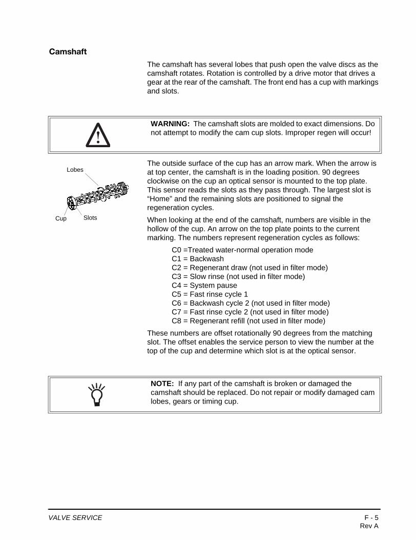
Camshaft
The camshaft has several lobes that push open the valve discs as the camshaft rotates. Rotation is controlled by a drive motor that drives a gear at the rear of the camshaft. The front end has a cup with markings and slots.
The outside surface of the cup has an arrow mark. When the arrow is at top center, the camshaft is in the loading position. 90 degrees clockwise on the cup an optical sensor is mounted to the top plate. This sensor reads the slots as they pass through. The largest slot is “Home” and the remaining slots are positioned to signal the regeneration cycles.
When looking at the end of the camshaft, numbers are visible in the hollow of the cup. An arrow on the top plate points to the current marking. The numbers represent regeneration cycles as follows:
C0 =Treated water-normal operation modeC1 = BackwashC2 = Regenerant draw (not used in filter mode)C3 = Slow rinse (not used in filter mode)C4 = System pauseC5 = Fast rinse cycle 1C6 = Backwash cycle 2 (not used in filter mode)C7 = Fast rinse cycle 2 (not used in filter mode)C8 = Regenerant refill (not used in filter mode)
These numbers are offset rotationally 90 degrees from the matching slot. The offset enables the service person to view the number at the top of the cup and determine which slot is at the optical sensor.
WARNING: The camshaft slots are molded to exact dimensions. Do not attempt to modify the cam cup slots. Improper regen will occur!
Slots
Lobes
Cup
NOTE: If any part of the camshaft is broken or damaged the camshaft should be replaced. Do not repair or modify damaged cam lobes, gears or timing cup.
VALVE SERVICE F - 5Rev A

To remove camshaft:1. Disconnect power to the unit.
2. Remove cover.
3. Remove motor.
4. Camshaft should be in the treated water position. Rotate counterclockwise as needed.
5. Use a screwdriver to hold open the #1 valve disc.
6. Move the camshaft backwards, away from the controller.
7. Lift the loose front end up and out.
To install camshaft:1. Check that the optical sensor is in position.
2. Position camshaft above the valve discs. The arrow on the cup should be up.
3. Slide the rear of the camshaft into place.
4. Pivot the camshaft close to its final position.
The camshaft will push on one or more valve discs. You will feel resistance as you complete the installation.
5. Move the camshaft down and into position. Force valve discs to move as needed.
6. Move the camshaft forward. Check that the optical sensor is in position.
7. Install motor.
NOTE: When replacing/removing camshaft, make sure not to damage or mis-align the optical sensor. Hold the sensor in position while removing camshaft.
NOTE: The camshaft will position itself to C0 (treated water) when the controller is powered up.
F - 6 VALVE SERVICERev A
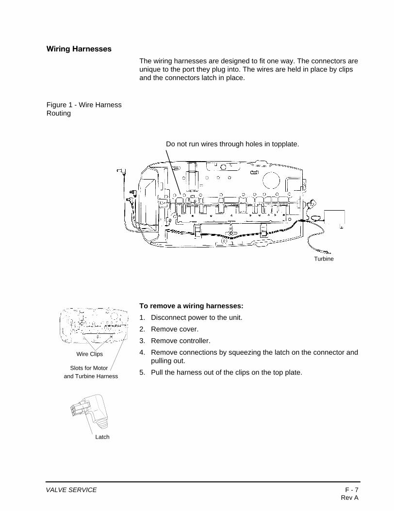
Wiring Harnesses
The wiring harnesses are designed to fit one way. The connectors are unique to the port they plug into. The wires are held in place by clips and the connectors latch in place.
Figure 1 - Wire Harness Routing
To remove a wiring harnesses:1. Disconnect power to the unit.
2. Remove cover.
3. Remove controller.
4. Remove connections by squeezing the latch on the connector and pulling out.
5. Pull the harness out of the clips on the top plate.
Do not run wires through holes in topplate.
Turbine
Wire Clips
Slots for Motor and Turbine Harness
Latch
VALVE SERVICE F - 7Rev A
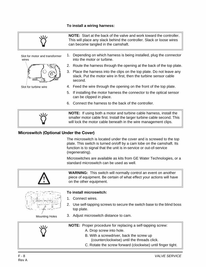
To install a wiring harness:
1. Depending on which harness is being installed, plug the connector into the motor or turbine.
2. Route the harness through the opening at the back of the top plate.
3. Place the harness into the clips on the top plate. Do not leave any slack. Put the motor wire in first, then the turbine sensor cable second.
4. Feed the wire through the opening on the front of the top plate.
5. If installing the motor harness the connector to the optical sensor can be clipped in place.
6. Connect the harness to the back of the controller.
Microswitch (Optional Under the Cover)
The microswitch is located under the cover and is screwed to the top plate. This switch is turned on/off by a cam lobe on the camshaft. Its function is to signal that the unit is in-service or out-of-service (regenerating).
Microswitches are available as kits from GE Water Technologies, or a standard microswitch can be used as well.
To install microswitch:1. Connect wires.
2. Use self-tapping screws to secure the switch base to the blind boss top plate.
3. Adjust microswitch distance to cam.
NOTE: Start at the back of the valve and work toward the controller. This will place any slack behind the controller. Slack or loose wires can become tangled in the camshaft.
Slot for motor and transformer
Slot for turbine wire
wires
NOTE: If using both a motor and turbine cable harness, install the smaller motor cable first. Install the larger turbine cable second. This will lock the motor cable beneath in the wire management clips.
WARNING: This switch will normally control an event on another piece of equipment. Be certain of what effect your actions will have on the other equipment.
Mounting Holes
NOTE: Proper procedure for replacing a self-tapping screw:A. Drop screw into hole.B. With a screwdriver, back the screw up
(counterclockwise) until the threads click.C. Rotate the screw forward (clockwise) until finger tight.
F - 8 VALVE SERVICERev A

To remove microswitch:1. Disconnect power to the switch.
2. Remove cover.
3. Unscrew switch base from top plate.
4. Disconnect wires.
Microswitch (Optional - Front of Camshaft)
This microswitch is mounted behind the controller at the front end of the camshaft. The switch is mounted to the top plate. The cam for this switch is screwed to the front of the camshaft. This cam can be adjusted to activate the microswitch at any time during the regeneration cycle.
The front end cam switch is available as a kit from GE Water Technologies.
To remove microswitch:1. Disconnect power to the switch.
2. Remove cover.
3. Remove controller.
4. Unscrew switch from top plate.
5. Disconnect wires.
To install microswitch:1. Connect wires.
2. Screw switch base to top plate using the switch guide pin over screw boss.
3. Attach the switch cam to front of the camshaft with a self-tapping screw. Adjust to the appropriate cycle and tighten.
WARNING: The Autotrol valve is rated for low voltage (less than 48 volts) microswitch components only. Using a high voltage switch may result in damaged valves or fire and may interfere with electronic control function.
CamSwitch
WARNING: This switch will normally control an event on another piece of equipment. Be certain of what effect your actions will have on the other equipment.
Optional MicroswitchMount
HolePost
VALVE SERVICE F - 9Rev A

Spring (Valve Discs)
This spring is a one-piece metal spring that applies pressure to the valve discs holding them closed. The rotating camshaft overcomes this pressure to open the valve discs as needed. The shape of the spring is critical for proper operation.
To remove spring:1. Disconnect power to the unit.
2. Remove cover.
3. Remove motor.
4. Remove camshaft.
5. Place unit in bypass.
6. Release water pressure by pushing the last valve discs open with a screw driver.
7. Locate valve discs 2, 3 and 4 for 255 valve or valve discs 3, 4 and 5 for Performa valves.
8. Position yourself on the spring side of the valve discs.
9. Place two (or more) fingers on the flat part of the spring.
10. Move the fingers toward the valve discs and into the spring valley between the previously located valve discs.
11. By pulling back and up on the spring, the spring will pop out of the valley.
12. Pull back further to remove the spring.
NOTE: The cam for this switch is adjustable. To have the microswitch activate at a different point in the cycle, rotate the cam as needed. To rotate the cam loosen the center screw, tighten when the cam is in the new position.
WARNING: Do not attempt to straighten or repair this spring. If this spring is damaged, valve discs may not operate correctly.
Push open
Spring locked under tabs
Valve Discs
F - 10 VALVE SERVICERev A
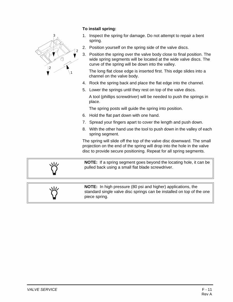
To install spring:1. Inspect the spring for damage. Do not attempt to repair a bent
spring.
2. Position yourself on the spring side of the valve discs.
3. Position the spring over the valve body close to final position. The wide spring segments will be located at the wide valve discs. The curve of the spring will be down into the valley.
The long flat close edge is inserted first. This edge slides into a channel on the valve body.
4. Rock the spring back and place the flat edge into the channel.
5. Lower the springs until they rest on top of the valve discs.
A tool (phillips screwdriver) will be needed to push the springs in place.
The spring posts will guide the spring into position.
6. Hold the flat part down with one hand.
7. Spread your fingers apart to cover the length and push down.
8. With the other hand use the tool to push down in the valley of each spring segment.
The spring will slide off the top of the valve disc downward. The small projection on the end of the spring will drop into the hole in the valve disc to provide secure positioning. Repeat for all spring segments.
12
3
2
NOTE: If a spring segment goes beyond the locating hole, it can be pulled back using a small flat blade screwdriver.
NOTE: In high pressure (80 psi and higher) applications, the standard single valve disc springs can be installed on top of the one piece spring.
VALVE SERVICE F - 11Rev A

Relay (Optional)
Holes are provided to mount a standard relay. It is located under the cover on the top plate. This relay is wired to the controller and changes the digital signal from controller into a signal that can be used to run accessories.
To install relay:1. Disconnect power to the unit.
2. Remove cover.
3. Remove controller.
4. Use self-tapping screws to secure the relay to the left side of top plate. Screw bosses are available for connecting relay.
5. Connect wires to the controller.
6. Clip wires with plastic tie-wrap to ensure that the wires do not tangle in camshaft.
Terminal Block (Optional)
Holes are provided to mount standard terminal blocks. The location is under the cover on the top plate.
To install terminal blocks:1. Disconnect power to unit.
2. Remove cover.
3. Use self-tapping screws to secure terminal block to top plate.
4. Clip wires with plastic tie-wrap to ensure that the wires do not tangle in camshaft.
WARNING: The Autotrol valve is rated for low voltage (less than 48 volts) microswitch components only. Using a high voltage switch may result in damaged valves or fire and may interfere with electronic control function.
Mounting Holes
WARNING: The Autotrol valve is rated for low voltage microswitch components only. Using a high voltage switch may result in damaged valves or fire and may interfere with electronic control function.
Mounting Holes
F - 12 VALVE SERVICERev A

Transformer (Optional)
A transformer is available to be mounted under the cover. Holes are provided on the top plate for a standard 24 VAC to 12 VAC transformer. This type of transformer is used when the plug-in AC adapter is not acceptable.
To install transformer:1. Disconnect power to unit.
2. Remove cover.
3. Use self-tapping screws to secure transformer to top plate.
4. Clip wires with plastic tie-wrap to ensure that the wires do not tangle in camshaft.
Top Plate
The top plate holds the valve discs in place during operation. This plate is removed to allow cleaning and replacing the valve discs.
To remove top plate:1. Disconnect power to unit.
2. Remove cover.
3. Remove motor.
4. Remove camshaft.
5. Place unit in bypass.
6. Release water pressure by pushing the last valve disc open with a screwdriver.
7. Any optional items may be removed.
8. Wiring harnesses should be removed.
9. Remove valve disc and spring.
10. Use a phillips screwdriver to remove the screws from the top plate.
11. Lift the top plate off. All the valve discs can be pulled straight out.
Inspect valve discs for wear. The sealing surface is the raised ridge on the underside of the top shoulder.
Check each valve disc cavity in the valve for debris. Remove any foreign objects before replacing the valve disc.
Mounting Holes
NOTE: The Autotrol valve discs are made from a chloramine resistant severe service rubber. The valve discs will usually not need to be changed. Before removing the top plate for valve disc service be certain that one of the discs is not operating correctly.
Remove screws
VALVE SERVICE F - 13Rev A

To install valve discs:
1. Put the valve disc into the correct (based on shoulder size) valve port cavity. The metal end without rubber coating should be visible.
2. Push down on the shoulder to position the valve disc completely into the port cavity.
The metal portion will be positioned straight up and the top of the shoulder will be level with the valve.
To install the top plate:
1. Position the top plate on top of the valve and over the valve discs.
2. Insert a screw at one of the corner positions.
A. Drop screw of same size and thread into the hole.B. Use a phillips screwdriver and lightly rotate the screw backwards
(counterclockwise).C. When the thread of the screw and the thread of the hole match,
the screw will “click” and slightly drop down.D. The threads are lined up. Lightly rotate the screw to tighten and
engage threads.E. Once the threads have engaged the screw can be tightened.
Minimal resistance will be present as the screw is turned in. Resistance indicates new threads are being formed. Back the screw out and rematch the threads.
3. Turn the screw in but do not tighten.
NOTE: If the valve disc fits properly in the cavity, it will work correctly.
NOTE: All valve discs should be in position. Use the same screws that were removed to reassemble the top plate.
WARNING: Follow the procedure to engage the screws with the existing threads. If the same threads are not used, the holding power of the screw is lost. Under pressure the valve can leak. Screws that have the same diameter but have different threads should not be used.
WARNING: This procedure for reinserting screws must be followed to ensure proper holding strength of the screws.
F - 14 VALVE SERVICERev A

4. Place a second screw into the hole diagonally opposite the first screw and turn in but do not tighten.
5. Insert another screw into one of the remaining corners and turn it in.
6. The fourth screw goes into the hole diagonally opposite. Turn it in.
7. Put the remaining screws in following the same criss-cross pattern working from the ends toward the center. When all the screws are in place they can be tightened down.
8. Start at the corner of the screw pattern and tighten that screw. Work the same pattern from the ends toward center and criss-crossing as each screw is tightened. Check that each valve disc moves smoothly before replacing the spring and camshaft.
9. Replace spring.
10. Replace camshaft and motor.
11. Replace controller and wiring harnesses.
1 5 9 11 7 3
4 8 12 10 6 2Screw Tightening Pattern
VALVE SERVICE F - 15Rev A

MAINTENANCE AND CLEANING—255, Performa (268, 263, 278, 273, Valves)
Preventive Maintenance (255 and Performa Valves)
Injector Screen and InjectorInspect and clean brine tank and screen filter on end of brine pickup tube once a year or when sediment appears in the bottom of the brine tank.
Clean injector screen and injector once a year:
1. Unplug the wall-mount transformer.
2. Remove cover. Shut off water supply or put bypass valve(s) into bypass position.
3. Relieve system and valve pressure:
A. For the 255 valve, use a screwdriver to press valve disc #5 slightly open. The pressure will escape quickly.
B. For the Performa valve, use a screwdriver to press valve disc #7 slightly open. The pressure will escape quickly.
4. Using a T-50 torx driver (recommended), or large flat blade screwdriver, remove injector screen and injector cap.
5. Clean injector screen using a fine brush. Flush under running water until clean.
6. Using a needle-nose pliers, pull injector straight out.
7. Flush water into the injector screen recess of the valve body to flush debris out through the injector recess.
8. Clean and flush the injector with water. Inspect for any debris in the venturi.
9. Lubricate the O-rings on the injector, injector cap and injector screen with silicone lubricant only!
10. Reinstall the injector, injector cap and injector screen. Be careful not to crimp or bend the O-rings.
NOTE: Many of the maintenance procedures involve O-rings. When re-assembling two parts with an O-ring seal, care must be taken with the placement of the O-ring. To properly install O-rings they should be lightly lubricated with silicone. Place the O-ring over the part feature that will be inserted into the hole. Do not start the assembly with the O-ring in the hole.
Injector and Cap
Injector Screen Filter
NOTE: Do not overtighten the plastic cap. Seat the cap lightly into position. Overtightening may cause breakage of the plastic cap that may not be immediately evident.
F - 16 MAINTENANCE AND CLEANING—255, Performa (268, 263, 278, 273, Valves)Rev A
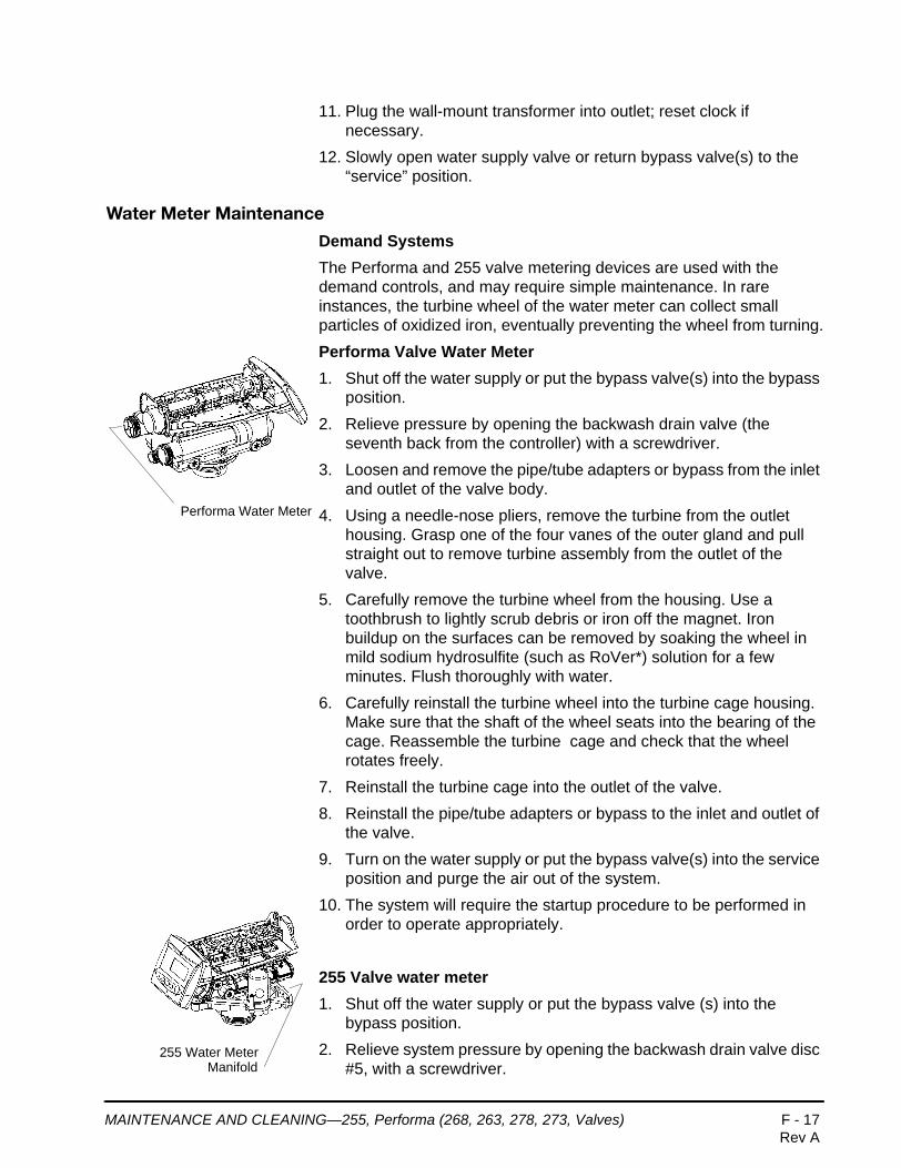
11. Plug the wall-mount transformer into outlet; reset clock if necessary.
12. Slowly open water supply valve or return bypass valve(s) to the “service” position.
Water Meter Maintenance
Demand SystemsThe Performa and 255 valve metering devices are used with the demand controls, and may require simple maintenance. In rare instances, the turbine wheel of the water meter can collect small particles of oxidized iron, eventually preventing the wheel from turning.
Performa Valve Water Meter1. Shut off the water supply or put the bypass valve(s) into the bypass
position.
2. Relieve pressure by opening the backwash drain valve (the seventh back from the controller) with a screwdriver.
3. Loosen and remove the pipe/tube adapters or bypass from the inlet and outlet of the valve body.
4. Using a needle-nose pliers, remove the turbine from the outlet housing. Grasp one of the four vanes of the outer gland and pull straight out to remove turbine assembly from the outlet of the valve.
5. Carefully remove the turbine wheel from the housing. Use a toothbrush to lightly scrub debris or iron off the magnet. Iron buildup on the surfaces can be removed by soaking the wheel in mild sodium hydrosulfite (such as RoVer*) solution for a few minutes. Flush thoroughly with water.
6. Carefully reinstall the turbine wheel into the turbine cage housing. Make sure that the shaft of the wheel seats into the bearing of the cage. Reassemble the turbine cage and check that the wheel rotates freely.
7. Reinstall the turbine cage into the outlet of the valve.
8. Reinstall the pipe/tube adapters or bypass to the inlet and outlet of the valve.
9. Turn on the water supply or put the bypass valve(s) into the service position and purge the air out of the system.
10. The system will require the startup procedure to be performed in order to operate appropriately.
255 Valve water meter1. Shut off the water supply or put the bypass valve (s) into the
bypass position.
2. Relieve system pressure by opening the backwash drain valve disc #5, with a screwdriver.
Performa Water Meter
255 Water Meter Manifold
MAINTENANCE AND CLEANING—255, Performa (268, 263, 278, 273, Valves) F - 17Rev A

3. Remove the four screws and nuts that are attaching the turbine manifold to the bypass valve or piping boss manifold. Pull the system away from the plumbing.
4. Using a needle-nose pliers, remove the turbine assembly from the outlet in the manifold. Grasp one of the vanes of the outer gland, and pull straight out to remove the assembly.
5. Carefully remove the turbine wheel from the housing. Use a toothbrush to lightly scrub debris or iron off the magnet. Iron buildup on the surface of the wheel can be removed by soaking the wheel in mild sodium hydrosulfite (such as RoVer*) solution for a few minutes. Flush thoroughly with water.
6. Carefully reinstall the turbine wheel into the turbine cage housing. Make sure that the shaft of the wheel seats into the bearing of the cage. Reassemble the turbine cage, and check that the wheel rotates freely.
7. Reinstall the turbine cage into the outlet of the turbine manifold.
8. Line the system up with the bypass or piping boss manifold. Verify that the O-rings are in place at the inlet, outlet and drain ports. Reattach the manifold using the four screws and nuts.
9. Turn on the water supply or put bypass valve(s) in the service (normal operation) position slowly, and allow air to purge from the system.
10. The system will require the startup procedure to be performed in order to operate appropriately.
*RoVer is a trademark of Hach Chemical Company.
Check Turbine Operation
After the turbine has been cleaned, verify that the turbine is accurately working. Repressurize the conditioner system, and verify that the controller is plugged in. Completely turn on a faucet that is plumbed after the conditioning system. After a few seconds, the display should be flashing a small faucet icon with water drops. If this is flashing, the turbine is operating properly.
If the faucet icon does not flash, then the system may have a faulty turbine probe cable wire harness. Replace that harness and repeat the steps above for checking for turbine operation.
Turbine Assembly
F - 18 MAINTENANCE AND CLEANING—255, Performa (268, 263, 278, 273, Valves)Rev A
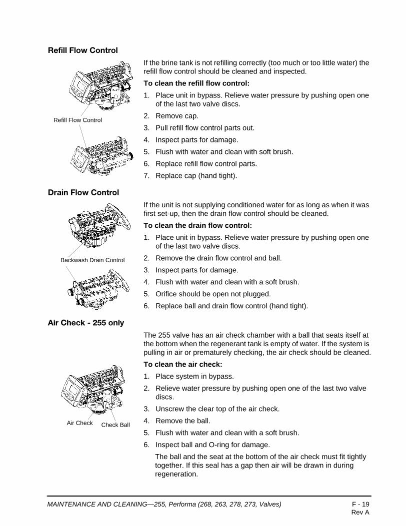
Refill Flow Control
If the brine tank is not refilling correctly (too much or too little water) the refill flow control should be cleaned and inspected.
To clean the refill flow control:1. Place unit in bypass. Relieve water pressure by pushing open one
of the last two valve discs.
2. Remove cap.
3. Pull refill flow control parts out.
4. Inspect parts for damage.
5. Flush with water and clean with soft brush.
6. Replace refill flow control parts.
7. Replace cap (hand tight).
Drain Flow Control
If the unit is not supplying conditioned water for as long as when it was first set-up, then the drain flow control should be cleaned.
To clean the drain flow control:1. Place unit in bypass. Relieve water pressure by pushing open one
of the last two valve discs.
2. Remove the drain flow control and ball.
3. Inspect parts for damage.
4. Flush with water and clean with a soft brush.
5. Orifice should be open not plugged.
6. Replace ball and drain flow control (hand tight).
Air Check - 255 only
The 255 valve has an air check chamber with a ball that seats itself at the bottom when the regenerant tank is empty of water. If the system is pulling in air or prematurely checking, the air check should be cleaned.
To clean the air check:1. Place system in bypass.
2. Relieve water pressure by pushing open one of the last two valve discs.
3. Unscrew the clear top of the air check.
4. Remove the ball.
5. Flush with water and clean with a soft brush.
6. Inspect ball and O-ring for damage.
The ball and the seat at the bottom of the air check must fit tightly together. If this seal has a gap then air will be drawn in during regeneration.
Refill Flow Control
Backwash Drain Control
Air Check Check Ball
MAINTENANCE AND CLEANING—255, Performa (268, 263, 278, 273, Valves) F - 19Rev A

7. Place ball on seat.
8. Check O-ring on air check housing and place it in position.
9. Hand tighten screws. If you removed the regenerant draw hose, replace it.
F - 20 MAINTENANCE AND CLEANING—255, Performa (268, 263, 278, 273, Valves)Rev A

AFTER SERVICE START-UPWhenever the controller is unplugged or the system is put in bypass for maintenance, a start-up is required. This start-up is not normally as extensive as the new system start-up procedure needs to be followed.
The initial power-up procedure should be used if a new controller or a new valve has been installed. This procedure is explained in the users manual.
The following service start-up procedure can be used when the controller was programmed prior to servicing the unit and removing power. The unit should be fully assembled with the cover off.
To start-up after service:1. Plug the transformer into the controller. Resin/media volume
should not need to be entered. If the display is flashing three dashes and a decimal point, refer to initial power-up procedure.
2. Set time of day and day of week if necessary.
The display will flash four dashes and a colon if the time of day needs to be set. If the display shows the correct time, proceed to step 5.
3. The UP and DOWN arrows are used to set the time of day. When the correct time is displayed push SET. If using the 12 hour setting PM will be displayed behind the time. AM is not designated.
4. Use the UP and DOWN arrow buttons to move a small flag (box) at the top of the display under the day of the week. When the correct day is flagged push SET.
The controller is ready to operate. The media tank should be ready for operation.
5. Hold the REGEN button on the controller down for five seconds. This will initiate a manual regeneration. The controller will indicate that the motor is turning the camshaft to the C1 cycle (Backwash) position. The display will show the total regen time remaining and the hourglass will flash when the motor is running.
6. Open the supply valve to the 1/4 open position. Any air in the media tank and valve will escape from the valves’ drain line.
7. Open supply valve to full open.
8. Advance the controller to the Refill Position. From cycle C1 (Backwash), press and hold the SET button. This will display the current cycle. Press the UP arrow to advance to the next cycle.
NOTE: Time of day and day of week settings are stored in a temporary memory and will be maintained at least 8 hours.
AFTER SERVICE START-UP F - 21Rev A

Continue to advance through each cycle until you have reached cycle C9 (Refill).
9. Allow a small amount of water to flow into the regenerant tank. Press SET and UP buttons simultaneously to advance to the treated water position.
10. Turn on a faucet and run the water until it is clear.
The unit is ready for operation.
NOTE: As you advance through each cycle there will be a slight delay before you can advance to the next cycle. The hourglass icon will flash while the camshaft is indexing to each cycle. There may be a pause at cycle C4 (System Pause). This cycle allows the water pressure to equalize on each side of the valve discs before moving on to the next cycle. The hourglass will flash indicating that the system is paused.
F - 22 AFTER SERVICE START-UPRev A

CONTROLLER TROUBLESHOOTING
Problem Solution
ERR 1 displayed Controller power has been connected and the control is not sure of the state of operation.
Press the UP arrow and the control should reset.
ERR 2 displayed Controller power does not match 50 or 60 Hz.
Disconnect and reconnect the power.If problem persists, obtain the appropriate controller for either 50 or 60 Hz power.
ERR 3 displayed Controller does not know the position of the camshaft. Camshaft should be rotating to find home position.
Wait for 2 minutes for the controller to return to HOME position. The hourglass should be flashing on the display indicating the motor is running.
Camshaft is not turning during ERR 3 display
Check that motor is connected.Verify that motor wire harness is connected to motor and controller module.Verify that optical sensor is connected and in place.Verify that motor gear has engaged cam gear.If everything is connected, try replacing in this order:
— Wire harness— Motor— Optical sensor—Controller
If camshaft is turning for more than 5 minutes to find HOME position:
Verify that optical sensor is in place and connected to wire.Verify that camshaft is connected appropriately.Verify that no dirt or rubbish is clogging any of the cam slots.If motor continues to rotate indefinitely, replace the following components in this order:
— Optical sensor— Wire harness— Motor— Controller
CONTROLLER TROUBLESHOOTING F - 23Rev A

255 VALVE FLOW DIAGRAMS
255 Valve Flow Diagrams
Control Valve Identification
Regenerant (1)Inlet (2)
Bypass (4)Outlet (3)
Rinse Drain (5)
Backwash/Drain (6)
C0 Treated Water Position
Untreated Water
Treated Water
RegenerantTankResin/media Tank
Inlet
Outlet 3
1
24
5 6 6
DrainDrainControl
Air Check
Untreated Water
Backwash
RegenerantTankResin/media Tank
Inlet
Outlet 3
1
24
5 6 6
DrainDrainControl
Air Check
Valve No.1 - Closed2 - Open3 - Open4 - Closed5 - Closed6 - Closed
Valve No.1 - Closed2 - Closed3 - Open4 - Open5 - Closed6 - Open
C1 Backwash 1 Position(normal operation)
G - 2 255 VALVE FLOW DIAGRAMSRev A

C
C
Va N1 2 3 4 5 6
Untreated Water
Regenerant
RegenerantTankMedia/Resin Tank
Inlet
Outlet 3
1
24
5 6 6
DrainDrainControl
Air Check
Untreated Water
Regenerant
RegenerantTankMedia/Resin Tank
Inlet
Outlet 3
1
24
5 6 6
DrainDrainControl
Air Check
Untreated Water
Rinse
Regenerant TankMedia/Resin Tank
Inlet
Outlet 3
1
24
5 6 6
DrainDrainControl
Air CheckUntreated Water
Rinse
RegenerantTankMedia/resin Tank
Inlet
Outlet 3
1
24
5 6 6
DrainDrainControl
Air Check
Valve No.1 - Open2 - Closed3 - Closed4 - Open5 - Open6 - Closed
2 Draw Position
Valve No.1 - Open2 - Closed3 - Closed4 - Open5 - Open6 - Closed
C3 Slow Rinse Position
C5 Fast Rinse 1 Position
Valve No.1 - Closed2 - Open3 - Closed4 - Open5 - Open6 - Closed
4 System Pause Position (repressurize)
lve o.- Closed- Closed- Closed- Open- Closed- Closed
255 VALVE FLOW DIAGRAMS G - 3Rev A
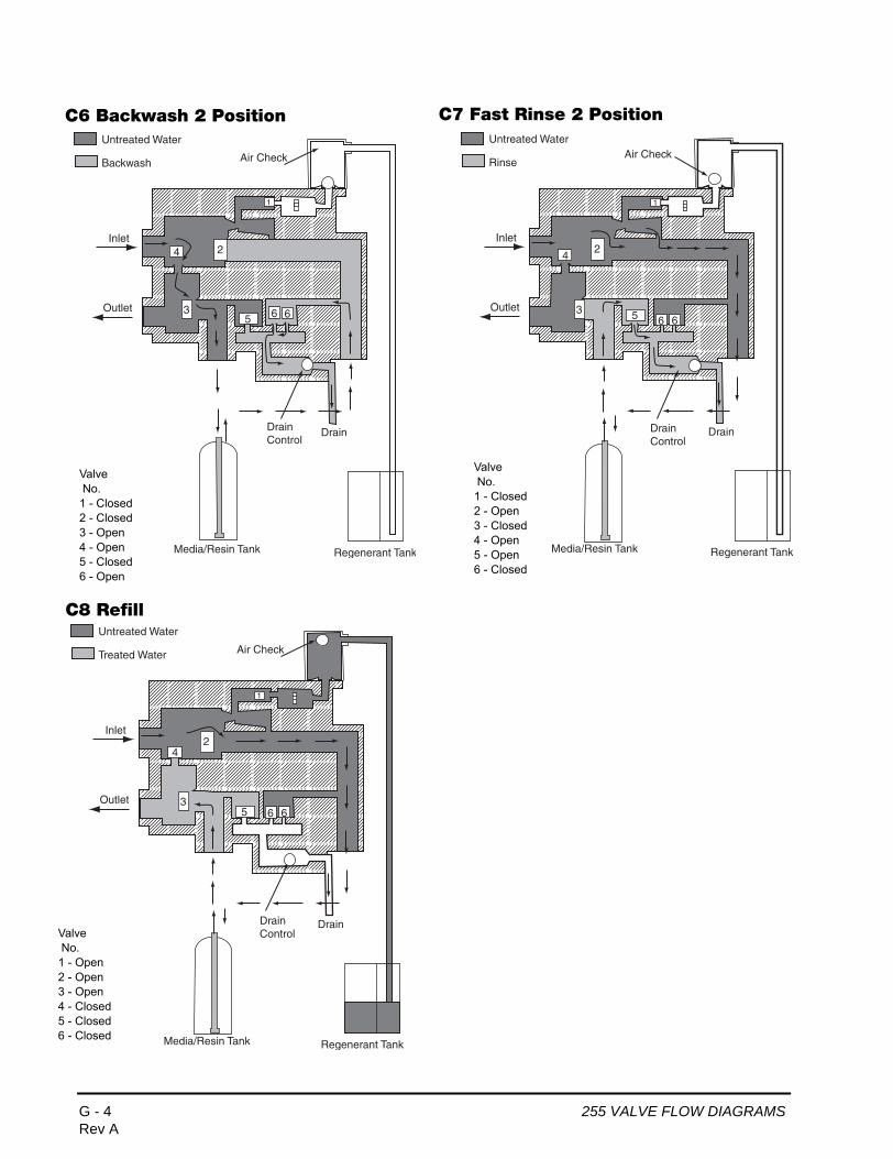
C
C
Va N1 2 3 4 5 6
Untreated Water
Backwash
Regenerant TankMedia/Resin Tank
Inlet
Outlet 3
1
24
5 6 6
DrainDrainControl
Air Check
Untreated Water
Treated Water
Regenerant TankMedia/Resin Tank
Inlet
Outlet 3
1
24
5 6 6
DrainDrainControl
Air Check
Valve No.1 - Closed2 - Closed3 - Open4 - Open5 - Closed6 - Open
6 Backwash 2 Position C7 Fast Rinse 2 Position
8 Refill
lve o.- Open- Open- Open- Closed- Closed- Closed
Untreated Water
Rinse
Regenerant TankMedia/Resin Tank
Inlet
Outlet 3
1
24
5 6 6
DrainDrainControl
Air Check
Valve No.1 - Closed2 - Open3 - Closed4 - Open5 - Open6 - Closed
G - 4 255 VALVE FLOW DIAGRAMSRev A
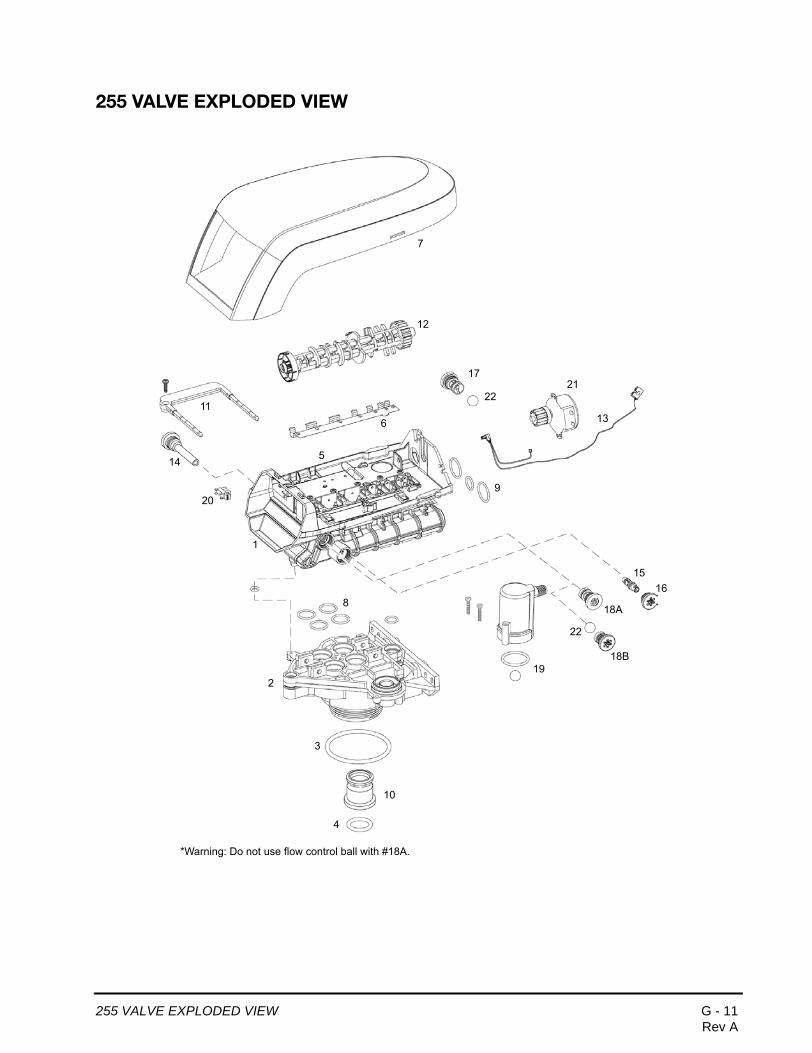
255 VALVE EXPLODED VIEW
1
2
3
4
5
6
7
8
9
11
12
14
1516
10
18A
20
2117
19
13
18B
*Warning: Do not use flow control ball with #18A.
22
22
255 VALVE EXPLODED VIEW G - 11Rev A
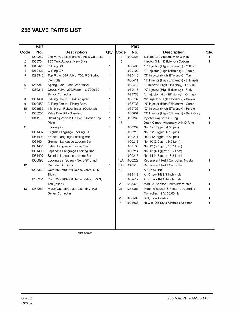
255 VALVE PARTS LIST
*Not Shown
Code
Part
No. Description Qty. Code
Part
No. Description Qty.1 1000232 255 Valve Assembly, w/o Flow Controls 1 14 1000226 Screen/Cap Assembly w/ O-Ring 12 1033784 255 Tank Adapter New Style 1 15 Injector (High Efficiency) Options 13 1010429 O-Ring BN 1 1030408 “E” Injector (HIgh Efficiency) - Yellow4 1010428 O-Ring EP 1030409 “F” Injector (High Efficiency) - Peach5 1235340 Top Plate, 255 Valve, 700/860 Series 1 1030410 “G” Injector (High Efficiency) - Tan
Controller 1030411 “H” Injector (High Efficiency) - Lt Purple6 1235341 Spring, One Piece, 255 Valve 1 1030412 “J” Injector (High Efficiency) - Lt Blue7 1236246* Cover, Valve, 255/Performa, 700/860 1 1030413 “K” Injector (High Efficiency) - Pink
Series Controller 1035736 “L” Injector (High Efficiency) - Orange8 1001404 O-Ring Group: Tank Adapter 1 1035737 “M” Injector (High Efficiency) - Brown9 1040459 O-Ring Group: Piping Boss 1 1035738 “N” Injector (High Efficiency) - Green
10 1001986 13/16 inch Rubber Insert (Optional) 1 1035739 “Q” Injector (High Efficiency) - Purple* 1000250 Valve Disk Kit - Standard 1 1035884 “R” Injector (High Efficiency) - Dark Gray* 1041196 Blending Valve Kit 900/700 Series Top 1 16 1000269 Injector Cap with O-Ring 1
Plate 17 Drain Control Assembly with O-Ring 111 Locking Bar 1 1000209 No. 7 (1.2 gpm; 4.5 Lpm)
1031402 English Language Locking Bar 1000210 No. 8 (1.6 gpm; 6.1 Lpm)1031403 French Language Locking Bar 1000211 No. 9 (2.0 gpm; 7.6 Lpm)1031404 German Language Locking Bar 1000212 No. 10 (2.5 gpm; 9.5 Lpm)1031405 Italian Language Locking/Bar 1002130 No. 12 (3.5 gpm; 13.2 Lpm)1031406 Japanese Language Locking Bar 1000214 No. 13 (4.1 gpm; 15.5 Lpm)1031407 Spanish Language Locking Bar 1000215 No. 14 (4.8 gpm; 18.2 Lpm)1006093 Locking Bar Screw - No. 8-9/16 inch 18A 1000222 Regenerant Refill Controller, No Ball 1
12 Camshaft Options 1 18B 1243510 Regenerant Refill Controller1235353 Cam 255/700-860 Series Valve, STD, 19 Air Check Kit 1
Black 1032416 Air Check Kit 3/8-inch male1236251 Cam 255/700-860 Series Valve, TWIN, 1032417 Air Check Kit 1/4-inch male
Tan (insert) 20 1235373 Module, Sensor, Photo Interrupter 113 1235269 Motor/Optical Cable Assembly, 700 1 21 1235361 Motor w/Spacer & Pinion, 700 Series 1
Series Controller Controller, 12 V, 50/60 Hz22 1030502 Ball, Flow Control 1* 1033066 New to Old Style Aircheck Adapter 1
G - 12 255 VALVE PARTS LISTRev A
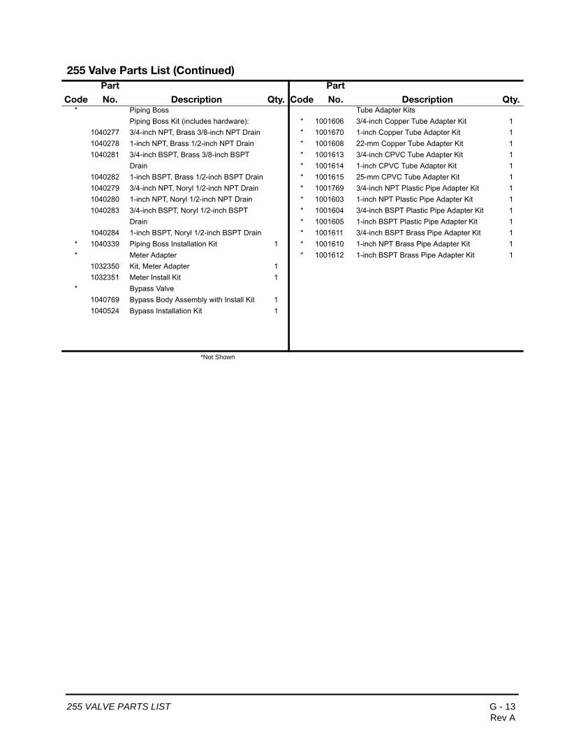
255 Valve Parts List (Continued)
*Not Shown
Code
Part
No. Description Qty. Code
Part
No. Description Qty.* Piping Boss Tube Adapter Kits
Piping Boss Kit (includes hardware): * 1001606 3/4-inch Copper Tube Adapter Kit 11040277 3/4-inch NPT, Brass 3/8-inch NPT Drain * 1001670 1-inch Copper Tube Adapter Kit 11040278 1-inch NPT, Brass 1/2-inch NPT Drain * 1001608 22-mm Copper Tube Adapter Kit 11040281 3/4-inch BSPT, Brass 3/8-inch BSPT * 1001613 3/4-inch CPVC Tube Adapter Kit 1
Drain * 1001614 1-inch CPVC Tube Adapter Kit 11040282 1-inch BSPT, Brass 1/2-inch BSPT Drain * 1001615 25-mm CPVC Tube Adapter Kit 11040279 3/4-inch NPT, Noryl 1/2-inch NPT Drain * 1001769 3/4-inch NPT Plastic Pipe Adapter Kit 11040280 1-inch NPT, Noryl 1/2-inch NPT Drain * 1001603 1-inch NPT Plastic Pipe Adapter Kit 11040283 3/4-inch BSPT, Noryl 1/2-inch BSPT * 1001604 3/4-inch BSPT Plastic Pipe Adapter Kit 1
Drain * 1001605 1-inch BSPT Plastic Pipe Adapter Kit 11040284 1-inch BSPT, Noryl 1/2-inch BSPT Drain * 1001611 3/4-inch BSPT Brass Pipe Adapter Kit 1
* 1040339 Piping Boss Installation Kit 1 * 1001610 1-inch NPT Brass Pipe Adapter Kit 1* Meter Adapter * 1001612 1-inch BSPT Brass Pipe Adapter Kit 1
1032350 Kit, Meter Adapter 11032351 Meter Install Kit 1
* Bypass Valve1040769 Bypass Body Assembly with Install Kit 11040524 Bypass Installation Kit 1
255 VALVE PARTS LIST G - 13Rev A

PERFORMA VALVE FLOW DIAGRAMS
C1 Backwash 1 Position
1 Regenerant Valve
2 Bypass Valve
3 Inlet Valve
4 Outlet Valve
5 Refill Valve
6 Rinse Drain Valve
7 Backwash Drain Valves
Performa Conditioner/Softener Flow Diagrams
Regenerant TankMedia/Resin Tank
Drain
Inlet
Outlet
Untreated Water
Treated Water
5
4
1
32
6 7
Regenerant TankMedia/resin Tank
Drain
Inlet
Outlet
Untreated Water
Treated Water
5
4
1
32
6 7BackwashFlowControl
C0 Treated Water Position
Valve No.1 - Closed2 - Closed3 - Open4 - Open5 - Closed6 - Closed7 - Closed
Valve No.1 - Closed2 - Open3 - Closed4 - Open5 - Closed6 - Closed7 - Open
Control Valve Identification
(normal operation)
H - 2 PERFORMA VALVE FLOW DIAGRAMSRev A
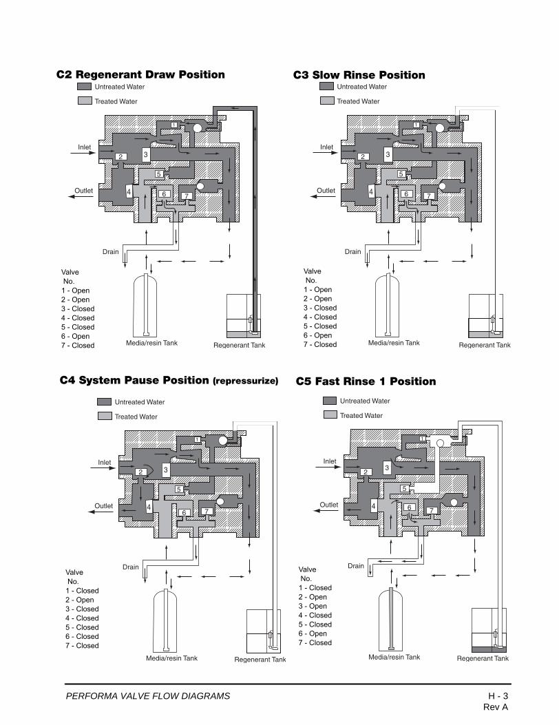
C
2 Regenerant Draw PositionC5 Fast Rinse 1 Position
Regenerant TankMedia/resin Tank
Drain
Inlet
Outlet
Untreated Water
Treated Water
5
4
1
32
6 7
Regenerant TankMedia/resin Tank
Drain
Inlet
Outlet
Untreated Water
Treated Water
5
4
1
32
6 7
Regenerant TankMedia/resin Tank
Drain
Inlet
Outlet
Untreated Water
Treated Water
5
4
1
32
6 7
Regenerant TankMedia/resin Tank
Drain
Inlet
Outlet
Untreated Water
Treated Water
5
4
1
32
76
Valve No.1 - Open2 - Open3 - Closed4 - Closed5 - Closed6 - Open7 - Closed
Valve No.1 - Closed2 - Open3 - Open4 - Closed5 - Closed6 - Open7 - Closed
C3 Slow Rinse Position
Valve No.1 - Open2 - Open3 - Closed4 - Closed5 - Closed6 - Open7 - Closed
C4 System Pause Position (repressurize)
Valve No.1 - Closed2 - Open3 - Closed4 - Closed5 - Closed6 - Closed7 - Closed
PERFORMA VALVE FLOW DIAGRAMS H - 3Rev A

Regenerant TankMedia/resin Tank
Drain
Inlet
Outlet
Untreated Water
Treated Water
5
4
1
32
6 7
Regenerant TankMedia/resin Tank
Drain
Inlet
Outlet
Untreated Water
Treated Water
5
4
1
32
6 7BackwashFlowControl
Valve No.1 - Closed2 - Closed3 - Open4 - Open5 - Open6 - Closed7 - Closed
C8 Refill Position
C6 Backwash 2 Position
Valve No.1 - Closed2 - Open3 - Closed4 - Open5 - Closed6 - Closed7 - Open
C7 Fast Rinse 2 Position
Regenerant TankMedia/resin Tank
Drain
Inlet
Outlet
Untreated Water
Treated Water
5
4
1
32
6 7
Valve No.1 - Closed2 - Open3 - Open4 - Closed5 - Closed6 - Open7 - Closed
H - 4 PERFORMA VALVE FLOW DIAGRAMSRev A
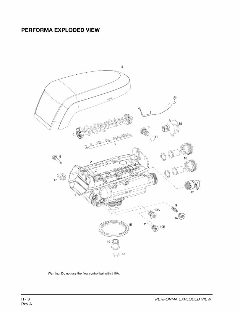
PERFORMA EXPLODED VIEW
2
1
3
4
5
6
7
8
910A
11
12
13
14
16
17
18
15
19
10B11
Warning: Do not use the flow control ball with #10A.
H - 8 PERFORMA EXPLODED VIEWRev A

PERFORMA PARTS LIST
*Not shown on drawing.
Code
Part
No. Description Qty. Code
Part
No. Description Qty.1 1035807 Valve Assembly w/o Flow Controls 1 9 Injector (High Efficiency) Options2 1235338* Top Plate, 268/700 Series Valves 1 1030408 “E” Injector (HIgh Efficiency) - Yellow3 1235339* Valve Disc Spring, One Piece, Performa 1 1030409 “F” Injector (High Efficiency) - Peach
Valve 1030410 “G” Injector (High Efficiency) - Tan4 1236246* Cover, Valve, 255/Performa 700/860 Series 1 1030411 “H” Injector (High Efficiency) - Lt Purple
Controller 1030412 “J” Injector (High Efficiency) - Lt Blue5 Performa Logix Camshafts 1 1030413 “K” Injector (High Efficiency) - Pink
1235352* Cam, 263-268/700-860 Series Valve, STD, 1035736 “L” Injector (High Efficiency) - OrangeBlack 1035737 “M” Injector (High Efficiency) - Brown
1237402* Cam, 269/700-860 Series Valve, STD, 1035738 “N” Injector (High Efficiency) - GreenGreen 1035739 “Q” Injector (High Efficiency) - Purple
1237403* Cam, 273/700-860 Series Valve, STD, Gray 1035884 “R” Injector (High Efficiency) - Dark Gray1237404* Cam, 273/700-860 Series Valve, TWIN 1032978 Plugged Injector for 263 Filter
(insert) 1032985 Plugged Injector Cap1237405* Cam, 278/700-860 Series Valve, STD, 10A 1000222 Regenerant Refill Controller, No Ball 1
Brown 10B 1243510 Regenerant Refill Controller1237406* Cam, 278/700-860 Series Valve, TWIN, Tan 11 1030502 Ball, Refill Flow Control
(insert) * 1030334 Plugged Refill Flow Control - for 263 6 Drain Control Assembly: 1 Valve
1000209 No. 7 (1.2 gpm; 4.5 Lpm) 12 1002449 Drain Fitting Elbow (3/4-inch hose 11000210 No. 8 (1.6 gpm; 6.1 Lpm) barbed)1000211 No. 9 (2.0 gpm; 7.6 Lpm) 13 1010428 O-Ring 11000212 No. 10 (2.5 gpm; 9.5 Lpm) 15 1000269 Injector Cap with O-Ring 11000213 No. 12 (3.5 gpm; 13.2 Lpm) 16 1035622 Tank Ring 11000214 No. 13 (4.1 gpm; 15.5 Lpm) * 1041174 Valve Disc Kit: Standard1000215 No. 14 (4.8 gpm; 18.2 Lpm) 17 Plumbing Adapter Kits: 11041196 Blending Valve Kit 900/700 Series Top Plate 1001606 3/4-inch Copper Tube Adapter Kit
* Drain Line Flow Control 1 1001670 1-inch Copper Tube Adapter Kit1030355 Drain Line Flow Control, 5 gpm (19 Lpm) 1001608 22-mm Copper Tube Adapter Kit1030356 Drain Line Flow Control, 6 gpm (22.5 Lpm) 1001613 3/4-inch CPVC Tube Adapter Kit1030357 Drain Line Flow Control, 7 gpm (26.5 Lpm) 1001614 1-inch CPVC Tube Adapter Kit1030358 Drain Line Flow Control, 8 gpm (30 Lpm) 1001615 25-mm CPVC Tube Adapter Kit1030359 Drain Line Flow Control, 9 gpm (34 Lpm) 1001769 3/4-inch NPT Plastic Pipe Adapter Kit1030360 Drain Line Flow Control, 10 gpm (38 Lpm) 1001603 1-inch NPT Plastic Pipe Adapter Kit
7 1235269 Motor/Optical Cable Assembly, 700 Series 1 1001604 3/4-inch BSPT Plastic Pipe Adapter KitController 1001605 1-inch BSPT Plastic Pipe Adapter Kit
8 1000226 Screen/Cap Assembly w/ O-Ring 1 1001611 3/4-inch BSPT Brass Pipe Adapter Kit1001610 1-inch NPT Brass Pipe Adapter Kit1001612 1-inch BSPT Brass Pipe Adapter Kit
18 1235373 Module, Sensor, Photo Interrupter 119 1235361 Motor w/Spacer & Pinion, 700 Series
Controller, 12 V, 50/60 Hz1
20 1001986 13/16 inch Rubber Insert (Optional) 1
PERFORMA PARTS LIST H - 9Rev A
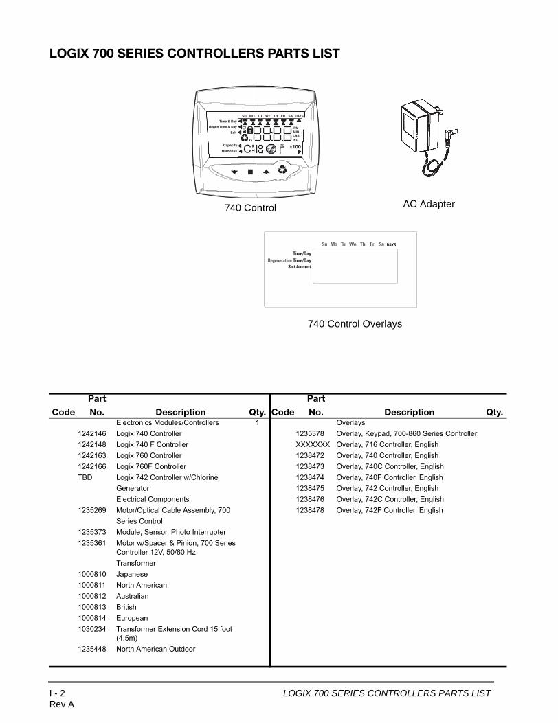
LOGIX 700 SERIES CONTROLLERS PARTS LIST
740 Control
Time & Day
Regen Time & Day
Salt
SU MO TU WE TH FR SA DAYS
LBS
PMMIN
KG
x100x2
PHC
Capacity
Hardness
AC Adapter
Time/Day
Su Mo Tu We Th Fr Sa DAYS
Regeneration Time/DaySalt Amount
740 Control Overlays
Code
Part
No. Description Qty. Code
Part
No. Description Qty.Electronics Modules/Controllers 1 Overlays
1242146 Logix 740 Controller 1235378 Overlay, Keypad, 700-860 Series Controller1242148 Logix 740 F Controller XXXXXXX Overlay, 716 Controller, English1242163 Logix 760 Controller 1238472 Overlay, 740 Controller, English1242166 Logix 760F Controller 1238473 Overlay, 740C Controller, EnglishTBD Logix 742 Controller w/Chlorine 1238474 Overlay, 740F Controller, English
Generator 1238475 Overlay, 742 Controller, EnglishElectrical Components 1238476 Overlay, 742C Controller, English
1235269 Motor/Optical Cable Assembly, 700 1238478 Overlay, 742F Controller, EnglishSeries Control
1235373 Module, Sensor, Photo Interrupter1235361 Motor w/Spacer & Pinion, 700 Series
Controller 12V, 50/60 Hz Transformer
1000810 Japanese1000811 North American1000812 Australian1000813 British1000814 European1030234 Transformer Extension Cord 15 foot
(4.5m)1235448 North American Outdoor
I - 2 LOGIX 700 SERIES CONTROLLERS PARTS LISTRev A

TS
Logix North American Controllers Default Settings
*stored in memory.
able 3 - Parameters Set with System Setup Calculated at 60 psi to cover from 30 to 90 psiystem Settings 1 thru 5
System Setting (1) System Setting (2) System Setting (3) System Setting (4) System Setting (5)
Tank Diameter (in) 6 6 7 8 9
Tank Height (in) 18 35 44 44 48
Injector E E F G H
Valve Model 255/268
Slow Rinse @ 60 psi (gpm)
0.08 0.08 0.11 0.15 0.21
Media/resin Volume (ft3)
0.15 0.25 0.5 0.75 1
Refill Rate (gpm) .33 .33 .33 .33 .33
Brine Draw Rate (gpm)
0.08 0.08 0.11 0.15 0.18
First Backwash(minutes)*
8 8 8 14 14
Pause-Re-pressurize (minutes)*
1 1 1 1 1
First Fast Rinse (minutes)
3 3 3 6 6
2nd Backwash (minutes)*
1 1 1 1 1
2nd Fast Rinse (minutes)*
1 1 1 1 1
Total Water Used
Salt Setting L S H L S H L S H L S H L S H
Salt Amount (lbs) 0.5 1 2 1 2 4 1.5 4.5 7.5 2.5 7 11 3.5 9 15
Capacity (lbs)* 2 3 4 4 6 8 6 13 15 11 19 23 15 25 30
Regenerant Draw (minutes)
2.4 4.7 9.4 4.7 9.4 18.9 5.2 15.5 25.8 6.3 17.6 27.7 7.3 18.9 31.5
Slow Rinse (minutes) 1.0 20.3 20.3 11.7 33.9 33.9 17 49.3 49.3 18.7 54.2 54.2 17.8 51.7 51.7
Draw + Rinse (minutes)*
9.5 25 30 16.5 43.5 53 22 65 75 25 72 82 25 70.5 83
Refill Time (minutes)* 0.5 1 2 1 2 4 1.5 4.5 7.5 2.5 7 11 3.5 9 15
I - 12 Rev A
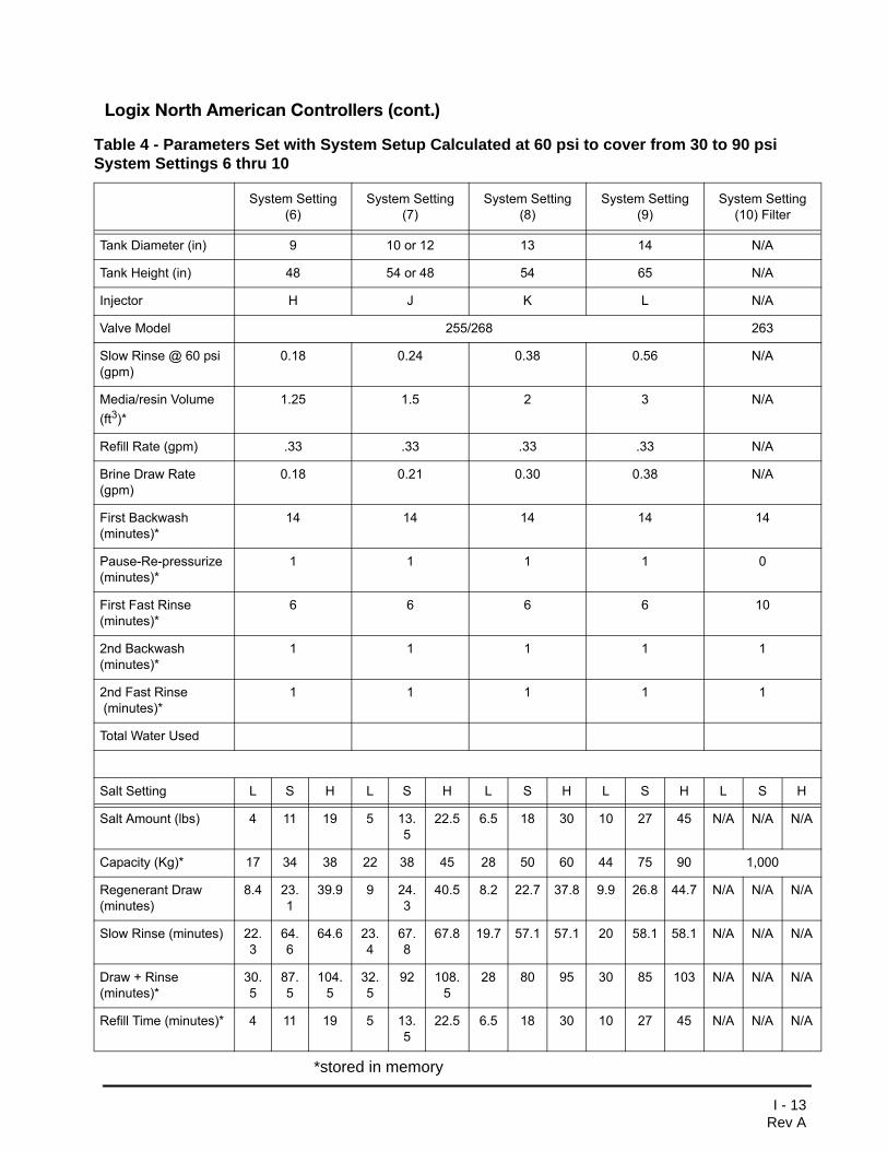
Logix North American Controllers (cont.)
*stored in memory
Table 4 - Parameters Set with System Setup Calculated at 60 psi to cover from 30 to 90 psi System Settings 6 thru 10
System Setting (6)
System Setting (7)
System Setting (8)
System Setting (9)
System Setting (10) Filter
Tank Diameter (in) 9 10 or 12 13 14 N/A
Tank Height (in) 48 54 or 48 54 65 N/A
Injector H J K L N/A
Valve Model 255/268 263
Slow Rinse @ 60 psi (gpm)
0.18 0.24 0.38 0.56 N/A
Media/resin Volume (ft3)*
1.25 1.5 2 3 N/A
Refill Rate (gpm) .33 .33 .33 .33 N/A
Brine Draw Rate (gpm)
0.18 0.21 0.30 0.38 N/A
First Backwash(minutes)*
14 14 14 14 14
Pause-Re-pressurize (minutes)*
1 1 1 1 0
First Fast Rinse (minutes)*
6 6 6 6 10
2nd Backwash (minutes)*
1 1 1 1 1
2nd Fast Rinse (minutes)*
1 1 1 1 1
Total Water Used
Salt Setting L S H L S H L S H L S H L S H
Salt Amount (lbs) 4 11 19 5 13.5
22.5 6.5 18 30 10 27 45 N/A N/A N/A
Capacity (Kg)* 17 34 38 22 38 45 28 50 60 44 75 90 1,000
Regenerant Draw (minutes)
8.4 23.1
39.9 9 24.3
40.5 8.2 22.7 37.8 9.9 26.8 44.7 N/A N/A N/A
Slow Rinse (minutes) 22.3
64.6
64.6 23.4
67.8
67.8 19.7 57.1 57.1 20 58.1 58.1 N/A N/A N/A
Draw + Rinse (minutes)*
30.5
87.5
104.5
32.5
92 108.5
28 80 95 30 85 103 N/A N/A N/A
Refill Time (minutes)* 4 11 19 5 13.5
22.5 6.5 18 30 10 27 45 N/A N/A N/A
I - 13Rev A

GE OSMONICS RESIDENTIAL VALVES AND CONTROLLERS LIMITED WARRANTY
For a period of five years (60 months) from the date of the manufacture of residential valves and controllers (timers) produced by GE Osmonics (we), we warrant that the Goods shall conform to our published specifications and shall be free from defects in material and workmanship when used with applications within our published specifications. This warranty applies to all residential control valve bodies, 1265 or 256 bypass valves, 400, 900 or 700 Series valve controllers (electronic or mechanical), or 700 series residential valve controller systems manufactured directly by GE Osmonics. Excessive weathering or component fatigue that causes valve or controller failure due to outdoor or harsh environment applications without adequate protection is not covered by this GE Osmonics limited warranty.
Any claim for breach of these warranties must be in writing and received by us within 60 months of the delivery of the Goods at issue, or the claim will be void. Our sole responsibility and your exclusive remedy for any breach of these warranties is limited to: (a) replacement of non-conforming Goods; or (b) re-performance of the goods at issue. Should applicable law prohibit this limitation of your remedies, then we agree that the maximum amount you may claim from us is twice the applicable portion of the net purchase price you paid us for the non-conforming Goods and Services. You, as the original purchaser, are not entitled to extend or transfer this warranty to any other party. The foregoing warranties are in lieu of and exclude all other warranties, statutory, express or implied, including any warranty of merchantability or of fitness for a particular purpose.
GE OSMONICS RESIDENTIAL VALVES AND CONTROLLERS LIMITED WARRANTY K - 3Rev A