WATER SERVICE BRANCH and METER PROCEDURES service from the right-of-way line up to and including the...
19
WATER SERVICE BRANCH and METER PROCEDURES Engineering Division/Branch Service Section
-
Upload
nguyentuyen -
Category
Documents
-
view
215 -
download
0
Transcript of WATER SERVICE BRANCH and METER PROCEDURES service from the right-of-way line up to and including the...
WATER SERVICE BRANCH and METER PROCEDURES
Engineering Division/Branch Service Section

Table of Contents General Overview ..................................................................................................................................................1
GCWW - Laws, Ordinances, Rules, Regulations and Standard Drawing References
Governing Service Branches ................................................................................................................................2
Service Branches – 2” or smaller on dedicated right-of-way ........................................................................... 2-3
Service Branch Applications for all size of fire branches, all portions of Dual or Tri-services, “curb-only” branches larger than 2”, and domestic or irrigation branches larger than 2” ................................................... 3-8
Large Branch Water Service Branch Checklist……………………………………………………………… 4 Cost of Service Branches ......................................................................................................................................9
Construction Water Prices .................................................................................................................................10
Valve Prices .........................................................................................................................................................10
Material Prices ....................................................................................................................................................10
Meter Prices .........................................................................................................................................................11
Curb Boxes ..........................................................................................................................................................12
Roadway Box Parts Prices .................................................................................................................................12
Mason Branch Costs ...........................................................................................................................................13 Mason Meter Costs .............................................................................................................................................14
Domestic Branch and Meter Sizing Table ................................................................................................... 15-16
Minimum Requirements: Residential .................................................................................................................16
Minimum Requirements: Commercial ...............................................................................................................16
Branch Material Data .........................................................................................................................................17
Rev. 4/2017
WATER SERVICE BRANCH and METER PROCEDURES
1 Rev. 4/2017
This document provides information and instructions on applying for water service within the Greater Cincinnati Water Works service area.
GENERAL OVERVIEW The Branch Services Section of the Greater Cincinnati Water Works (GCWW) Engineering Division coordinates the application process for new service branches. There are three different branch application processes dependent on the location and type of development. The three processes are: 1.) Subdivision “Curb Only” taps, 2” and smaller; 2.) Small branches 2” or smaller on dedicated right-of-way; 3.) All fire branches, Dual or Tri-Services, “Curb Only” branches larger than 2” and Domestic or Irrigation branches larger than 2” in size. The "Certified Person" referred to in this document, is one who holds a State of Ohio master plumber’s license and has taken the GCWW test to ensure that the applicant is familiar with our rules and regulations for installing service from the right-of-way line up to and including the meter setting or detector check setting. The test is given by appointment and you may schedule to take it by calling John Waters (513-591-7836) at least two days in advance. There is no charge for the test. However, you must purchase the GCWW Rules and Regulations manual ($8.00) (or) go online at http://www.cincinnati-oh.gov/water/permits-construction/records-services/laws-ordinances-rules-regulations/ and make a copy to bring with you when you take the test. The bond that is referred to is a $1,000 Certified Persons performance bond. The bond runs from January 1 to December 31. GCWW will provide the bond form for your insurance company to complete, or you can go online to: http://www.cincinnati-oh.gov/water/permits-construction/branch-meter-services and make a copy of the forms. Payment for branches and meters is made to the GCWW Cashier in cash, check or visa prior to receipt of service. Check should be made payable to the “Greater Cincinnati Water Works”.
WATER SERVICE BRANCH and METER PROCEDURES
2 Rev. 4/2017
GCWW - LAWS, ORDINANCES, RULES, REGULATIONS AND STANDARD DRAWING REFERENCES:
BRANCHES: Sections 401-31, 32, 33, 35, 36 and 41 METERS: Sections 401-43, 51, 52, 53, 54 and 55 STANDARD DRAWINGS: 108-1 thru 109-5B
1) SUBDIVISION/ “CURB ONLY” TAPS - 2" AND SMALLER ONLY When a new subdivision is being developed, the developer or a GCWW Certified Tapper completes a form D-100-S for each tap to be installed. All lots in the development must be provided with a tap. The SUBDIVISION BRANCH price from the rate table on page 6, only applies to these taps. In this case only materials are included (ferrule, curb stop and "blue top stake"). Insulator couplings are required and are an additional cost. The Certified Tapper performs the actual branch installation work with a GCWW Construction Inspector present. A meter is not purchased until after the individual lot is developed. (See Section 401-31R13 thru R16 and Section 401-33 of GCWW - Laws, Ordinances, Rules and Regulations for detailed requirements) GCWW Water Works Construction Inspection fees apply. 2) SERVICE BRANCHES - 2" OR SMALLER ON DEDICATED RIGHT-OF-WAY For new service on existing dedicated streets, an issued building permit or plumbing permit must be presented at time of application. Application must be made by a plumber or fire installer who is licensed with the State of Ohio, certified with GCWW, and must have a current Certified Persons performance bond with GCWW, either as an individual or one bond for their employing company. The following is the general procedure when applying for a service branch two inches or less in size.
1.) The applicant must complete a CROSS-CONNECTION QUESTIONNAIRE (CCQ - blue form). This card provides GCWW with information about branch and meter size, desired branch location as well as proposed use of the new service. The branch location is specified from the nearest fire hydrant and cross street as well as the side of the street that the tap will run to. EXAMPLE: You are building on the west side of Vine Street and the nearest cross street is Mitchell Avenue. Typical branch measurements would be- WEST SIDE OF VINE 105 FEET SOUTH OF THE FIRST FIRE HYDRANT SOUTH OF MITCHELL.
2.) Provide a plot plan showing property lines and all easements for each tap.
3.) All applicable service fees are charged at this time including meter, branch and bulk fee for unmetered
construction water. SEE TABLES BEGINNING ON PAGE 6 FOR PRICE LISTS. IN MOST CASES THE "ANY STREET" PRICE WILL APPLY TO THESE BRANCHES.
4.) After paying the cashier, the applicant picks up the meter and a "blue top" stake from our storeroom.
WATER SERVICE BRANCH and METER PROCEDURES
3 Rev. 4/2017
The stake is used by the applicant to mark the actual tap location. This process usually takes 15 to 30 minutes, depending on the number of people making application and how busy the cashiers are.
The next day the application goes to the Inspection Department for street opening permit and a field check of the tap location. Call (513) 591-7873 to inform the Tap Inspector, in the Inspection Department, that you have set the stake at the tap location. After we receive the street opening permit, the GCWW Tap Contractor will install the tap within 30 days. 3) SERVICE BRANCH APPLICATIONS FOR: All sizes of fire branches, all portions of Dual or Tri-services, “Curb-Only” branches larger than 2”, and Domestic or Irrigation branches larger than 2”.
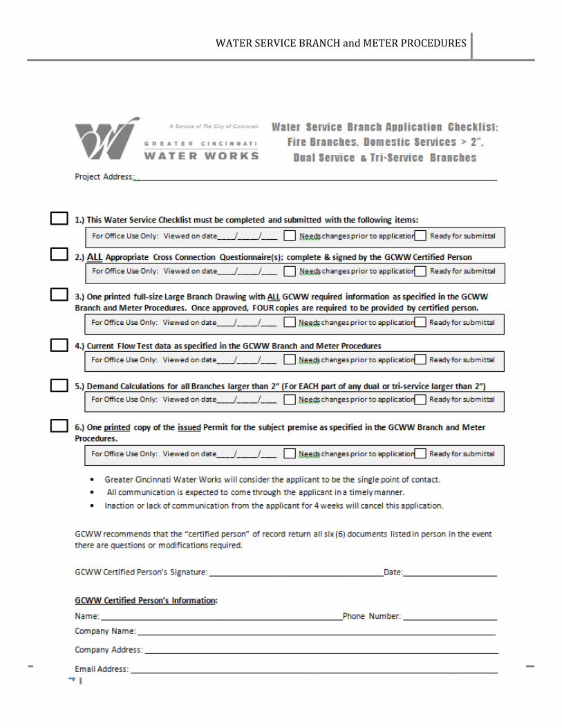
All of the six following complete elements of the application must be submitted together in order for the application to become active for review, approval and sale.
o Completed Application checklist o Completed and appropriately signed Cross Connection Questionnaire for each branch o Copy of issued full building, plumbing or fire suppression permit o Up to date and acceptably performed flow test data o Calculations for each branch 4” or larger o 4 copies of the final form of the branch application drawing
For large branches from the time of official application to installation, the average length of process time is 90 days; weather & environment conditions, main and branch maintenance & repair needs, and application numbers all impact this average time upward and downward. This is not a waiting period or guaranteed projected time-frame; it is an average projected length of time the course of this process takes. The Application Checklist A copy of this is included on the following page. Pads of checklists are available at 4747 Spring Grove Av. At the Engineering Front Counter. This will help the applicant project team keep track of the required application elements prior to application submittal. This checklist accompanied by the other 5 required items must be complete and submitted together before the application will be accepted by GCWW as an application in current review. If the applicant needs for one or more of these elements to have one preliminary review at the counter prior to submittal, that will be recorded on the checklist.
WATER SERVICE BRANCH and METER PROCEDURES
4 Rev. 4/2017
WATER SERVICE BRANCH and METER PROCEDURES
5 Rev. 4/2017
The Cross Connection Questionnaire (CCQ) There are materials at the permitting counter to outline GCWW’s Rules and Regulations and help the applicant properly fill out the CCQ. The form must be filled out in its entirety, with no questions left blank, including the Needed Fire Flow @ 20 PSI, which the applicants for fire service branches must obtain directly from the appropriate fire authority, and is not to be calculated by the applicant. For a dual service branch for which the same company will be performing the work for both the domestic and the fire branches, both the fire CCQ and the domestic CCQ must be filled out completely. For projects where the fire and domestic branches will be taken care of by two different companies, each company must completely fill out the appropriate fire or domestic CCQ. Each CCQ must be signed and dated by an appropriate authorized person: A licensed, certified, fire installer, registered with GCWW, representing a company holding a current bond, may fill out and sign a CCQ for a fire only CCQ or a dual (or more) branch (which would require both a fire and a domestic CCQ). A licensed, certified master plumber representing a company with a current bond may fill out a domestic CCQ for a domestic only branch, or a domestic CCQ for a domestic portion of a dual branch. The bond holder assumes the responsibility for the suitability of the applicant who is representing them. The Permit A copy of an issued permit is required to approve this application. The permit may be the general building permit, a plumbing permit, or a fire-suppression (sprinkler) permit, but cannot be a permit application, or a foundation, shell, HVAC or other permit. It cannot be just a submitted number, but must be an actual copy of the issued permit. This can be brought in, faxed to us (513-591-7878) or emailed to [email protected] or to [email protected] . Flow test There must be current flow test data for the area where the tap is to be made. Typically two fire hydrants, one to each side of where the tap is proposed, will be flowed and gauged. This flow test must have been performed within the last three years, or the applicant will be required to perform a new flow test. If a potential applicant wants to check on this prior to application, or to assist with their design process, please call our Engineering Records Section at (513) 591-7855 or email: [email protected] . Please be aware that flow test data, even if obtained from GCWW, may not be acceptable to us for application purposes if there have been system changes within the last 3 to 5 years. Contractor Performed Flow Tests As the contractor performing the proposed flow test you are required to do the following:
1.) Perform a valid flow test 2.) Collect all test data (date, time, nozzle size, static, residual & pitot pressures, and flow in GPM ) 3.) Submit flow test information to the Engineering Records Section.
a.) May be electronic or paper copy: [email protected] Fax (513-591-7878) b.) Must include a map or sketch showing cross streets, a north arrow and which fire hydrant was
flowed and which fire hydrant was gauged.
WATER SERVICE BRANCH and METER PROCEDURES
6 Rev. 4/2017
The following requirements are critical for the data to be accepted as a valid flow test: 1.) The hydrants which are flowed and gauged must be on the same size water main, ideally with no other
water mains teed off between the hydrants used in the flow test. 2.) For flow tests run for large branch applications, the hydrants used for flow tests should ideally be
located on either side of the location for the proposed branch.
PLEASE NOTE: GCWW valve personnel are present during the test to make sure the contractor does not damage the water distribution system. The GCWW valve personnel operate the fire hydrants and any necessary valves. They are not responsible for performing the test, or collecting data. GCWW considers the flow tests to be valid for a time period of 3-5 years. This timeframe will vary because of potential changes over time to the water distribution system where the flow test occurred. Calculations In order to make certain the system can provide the sustained flow that is needed for the new service; we need to see a copy of the calculations, indicating the peak flow and pressure needed. These calculations will show how the peak water demand requested on the application form was determined. This is true for all branches 4” or larger. This can be a print-out of the hydraulic calculations, a copy of part of a spreadsheet, or manual calculations. For domestic and irrigation service branches, this is typically a Fixture Unit Sheet. Plans One single plan sheet (or 2 copies, if the applicant wants a red-lined copy back) must be submitted with the application. If you prefer, after application and prior to printing, you may submit your revised application drawings via email to [email protected] or to [email protected] . When the plan itself is approved as satisfying all GCWW requirements, the applicant must provide 4 copies of the final draft of the plan sheet to GCWW Branch Services. The single plan sheets must comply with the following criteria:
1) Meter settings are required to be outside of the building.
2) Plans must show complete property/parcel including building footprints and all edges of pavement; existing and proposed. Plan sheet must be oriented so that the North arrow is pointing to the top or to the right of the plan sheet (in the x,x quadrant).
3) For commercial developments, RP backflow containment devices are required on all domestic
service branches; these are to be placed after the meter and immediately inside a heated structure, close in proximity to the right of way. The heated structure must be shown on the plan.
4) Plans must be in engineering or decimal scale; not architectural scale.
WATER SERVICE BRANCH and METER PROCEDURES
7 Rev. 4/2017
5) Proposed branch(es) and proposed pit must be shown graphically accurately; we require that all branches be a minimum of 10’ from hydrants and other GCWW fittings with blocking; 5’ minimum from the outside of all other appurtenances or permanent features.
6) Dimension the distance, in round numbers from the nearest fire hydrant to the proposed tap.
7) Label the dimension exactly as it is on the CCQ: N. S. E. or W. side of STREET NAME, NUMBER feet N. S. E. or W. of NUMBER FH N. S. E. or W. of STREET NAME. Ex: N side of Main, 130’ E of 1st FH N of Eggleston.
8) Label the FH: NUMBER FH N. S. E. or W. of STREET NAME. Ex. 1st FH N of Eggleston.
9) There may be no horizontal bends from the main to the pit box.
10) ALL existing and proposed utilities, utility connections, & appurtenances in the area of the proposed branch must be shown. Call 1-800-362-2764 for OUPS “preplanning information”. This must be completed by the applicant and the accuracy of the graphical depiction of the utilities, appurtenances and connections is entirely the responsibility of the applicant. During any part of the branch and meter setting installation, any costs or damages related to utility information NOT shown on the drawing will be the legal and financial responsibility of the signatory applicant.
11) For taps made in State Right-of-Way areas, profiles of proposed branch, main being tapped and
existing/proposed utilities/appurtenances must be provided and drawings must meet ODOT requirements
12) Applicant must check with municipality where tap is being made to determine whether an open-cut is appropriate for installing the branch. Bored & Cased is currently required on all large branches in areas where Hamilton County and the Ohio Department of Transportation is the permitting agency. Any bored & cased branch must include a profile of the branch on the drawing sheet, and must show the boring and receiving pits, and all crossing utilities within the right of way on the plan view.
13) Both sides of Right of Way must be shown, labeled and the width dimensioned. If the Right of Way is proposed; documentation from the appropriate authority must be provided, verifying the location of the proposed ROW and a date when proposed ROW will go into effect. If an easement is used in lieu of a ROW, a registered easement plat must be provided. Tax maps with accurate ROW information can be accessed at http://cagisonline.hamilton-co.org/cagisonline/index.html . In the “address” pull-down, choose “tax maps”, type in the book and page; e.g.: 194-12, hit “go” then click on the red arrow by the .pdf icon.
14) The Center Line, names of streets and edges of pavement must be shown and labeled.
15) Show accurately and label the main being tapped and its size.
WATER SERVICE BRANCH and METER PROCEDURES
8 Rev. 4/2017
16) Show all easement boundaries in the area of the property if applicable.
17) Show fire hydrant heads, valves & leads.
18) Include on the plan sheet a copy of the appropriate signed GCWW standard meter setting detail drawing. The most current signed, standard drawings can be found at: http://www.cincinnati-oh.gov/water/permits-construction/records-services/ in .pdf and .tiff formats, or hard copies of these can be obtained from Greater Cincinnati Water Works to be physically copied onto plan sheet. Altered or alternative drawings are not acceptable; only the signed approved standard detail.
19) Include on the plan sheet, legibly, the following statement, in its entirety:
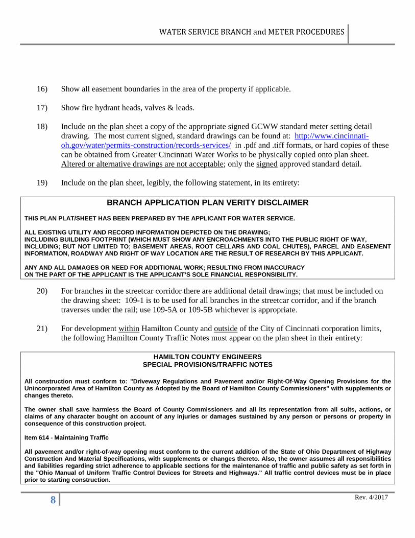
BRANCH APPLICATION PLAN VERITY DISCLAIMER
THIS PLAN PLAT/SHEET HAS BEEN PREPARED BY THE APPLICANT FOR WATER SERVICE. ALL EXISTING UTILITY AND RECORD INFORMATION DEPICTED ON THE DRAWING; INCLUDING BUILDING FOOTPRINT (WHICH MUST SHOW ANY ENCROACHMENTS INTO THE PUBLIC RIGHT OF WAY, INCLUDING; BUT NOT LIMITED TO; BASEMENT AREAS, ROOT CELLARS AND COAL CHUTES), PARCEL AND EASEMENT INFORMATION, ROADWAY AND RIGHT OF WAY LOCATION ARE THE RESULT OF RESEARCH BY THIS APPLICANT. ANY AND ALL DAMAGES OR NEED FOR ADDITIONAL WORK; RESULTING FROM INACCURACY ON THE PART OF THE APPLICANT IS THE APPLICANT’S SOLE FINANCIAL RESPONSIBILITY.
20) For branches in the streetcar corridor there are additional detail drawings; that must be included on
the drawing sheet: 109-1 is to be used for all branches in the streetcar corridor, and if the branch traverses under the rail; use 109-5A or 109-5B whichever is appropriate.
21) For development within Hamilton County and outside of the City of Cincinnati corporation limits, the following Hamilton County Traffic Notes must appear on the plan sheet in their entirety:
HAMILTON COUNTY ENGINEERS SPECIAL PROVISIONS/TRAFFIC NOTES
All construction must conform to: "Driveway Regulations and Pavement and/or Right-Of-Way Opening Provisions for the Unincorporated Area of Hamilton County as Adopted by the Board of Hamilton County Commissioners" with supplements or changes thereto. The owner shall save harmless the Board of County Commissioners and all its representation from all suits, actions, or claims of any character bought on account of any injuries or damages sustained by any person or persons or property in consequence of this construction project. Item 614 - Maintaining Traffic All pavement and/or right-of-way opening must conform to the current addition of the State of Ohio Department of Highway Construction And Material Specifications, with supplements or changes thereto. Also, the owner assumes all responsibilities and liabilities regarding strict adherence to applicable sections for the maintenance of traffic and public safety as set forth in the "Ohio Manual of Uniform Traffic Control Devices for Streets and Highways." All traffic control devices must be in place prior to starting construction.

WATER SERVICE BRANCH and METER PROCEDURES
9 Rev. 4/2017
Rates for Installation of Water Service Branches
Pursuant to the City Manager’s authority as set forth in section 40 1-94 of the Cincinnati Municipal Code, the rates described below shall apply to the installation of water service branches, effective May 20, 2015.
Class 3/4" 1" 1-1/2" 2" 4" 6" 8" 10" Any Street $2,775 $2,820 $3,020 $4,540 $7,950 $8,245 $9,700 $10,345 Unimproved $1,960 $2,235 $2,360 $3,860 $6,570 $6.705 $7,310 $7,905 Restricted $2,730 $2,760 $2,965 $4,450 $6,340 $6,405 $6,805 $7,925 Subdivision $390 $415 $525 $715 $1,665 $1,805 $2,195 $2,670 Domestic or Irrigation portion of Dual or Tri-Service Branch: 3/4"-$830, 1"-$955, 1-1/2"-$1,100, 2"-$1,265. Additional charges:
1. Add $80 for a STOP BOX or $120 for a ROADWAY BOX where required by GCWW. 2. Add $300 to the cost of a branch to be installed in a STATE HIGHWAY. 3. Add $2,455 for a branch 4" or larger on a 16" main; Add $2,685 for a branch 4" or larger on a 20" main. 4. Add $2,880 for each branch larger than 10". 5. Add $350 for each branch 4” or larger within the City of Cincinnati, plus an additional permit fee for
restricted street. Special Notes:
A) Branches installed at other than normal hours as required by the Customer or governing authority will require an additional overtime charge.
B) Street opening permits shall be obtained by Water Works’ Contractor except when the applicant must perform preparatory work with the right of way as required by the Water Works or governing authority.
C) A restricted street is one in which the governing authority will not permit excavation in the street paving. Where a special condition is deemed by Water Works to be present, restricted prices will apply to branches and the applicant will be responsible for the full cost of the work that exceeds the restricted price. Special conditions as determined by the greater Cincinnati Water Works which prohibit or prevent normal branch installations may include but are not limited to culvert, creek or rail crossings. The applicant shall perform all necessary excavations, tunneling, boring/casing and final restoration. Greater Cincinnati Water Works will perform all service branch work and backfill excavation at the water main. Backfilling of the boring pit must be done by the applicant. In some cases it may be necessary to install a stop cock in a position other than the property line. This point will be determined by the Water Works. Notwithstanding the above, where cathodic protection is required by Water Works, the applicant will be responsible for 40% of the total cost of materials and installation that exceeds the restricted price, and the Water Works will perform all work, including the installation of steel casing.
D) GCWW directed Plan 4 water main extension branch sales projects will use the Unimproved Street prices at GCWW discretion.
E) All material prices are for estimating purposes. Material costs are subject to change.

WATER SERVICE BRANCH and METER PROCEDURES
10 Rev. 4/2017
Construction Water Prices
Cincinnati Incorporated Hamilton Co. Clermont Co.
Unincorporated Hamilton Co.
Arlington Hts. Bulter Co. Mason Warren Co.
Venice Gardens
Cubic Feet
1 Family $129.00 $161.50 $172.00 $185.50 $266.00 50,000 2 Family $193.50 $242.25 $258.00 $278.25 $399.00 75,000 3 Family $225.75 $282.63 $301.00 $324.63 $465.50 87,500
Valve Prices
Size MJ Gate CJ Gate MJxFlange
tapping CJxFlange
tapping FLGxMJ
4 $334.69 $343.71 $422.20 $444.67 $319.83 6 $427.34 $452.37 $596.05 $604.50 $427.34 8 $680.12 $686.85 $885.43 $916.18 $667.54 10 $1,060.44 $1,060.44 12 $1,341.81 $1,390.86 $2016.08 $1,679.67 $1,280.62
Material Prices
Item Cost Item Cost 3/4 curb stop $56.22 4 x 1 service saddle $82.02 1" curb stop $76.73 4 x 1 1/2 service saddle $95.65 1 1/2 curb stop $167.61 4 x 2 service saddle $104.13 2 " curb stop $272.88 6 x 1 1/2 service saddle $110.46 curb box $41.24 6 x 2 service saddle $121.36 roadway boxes see page 9 8 x 1 1/2 service saddle $125.88 3/4 ferrule $37.69 8 x 2 service saddle $137.04 1" ferrule $48.36 10 x 1 1/2 service saddle $162.69 1 1/2 ferrule $104.68 10 x 2 service saddle $174.74 2" ferrule $183.27 1 1/2 insulator couplings $79.84 3/4 insulator coupling $26.31 2" insulator coupling $139.05 1" insulator coupling $48.36
WATER SERVICE BRANCH and METER PROCEDURES
11 Rev. 4/2017
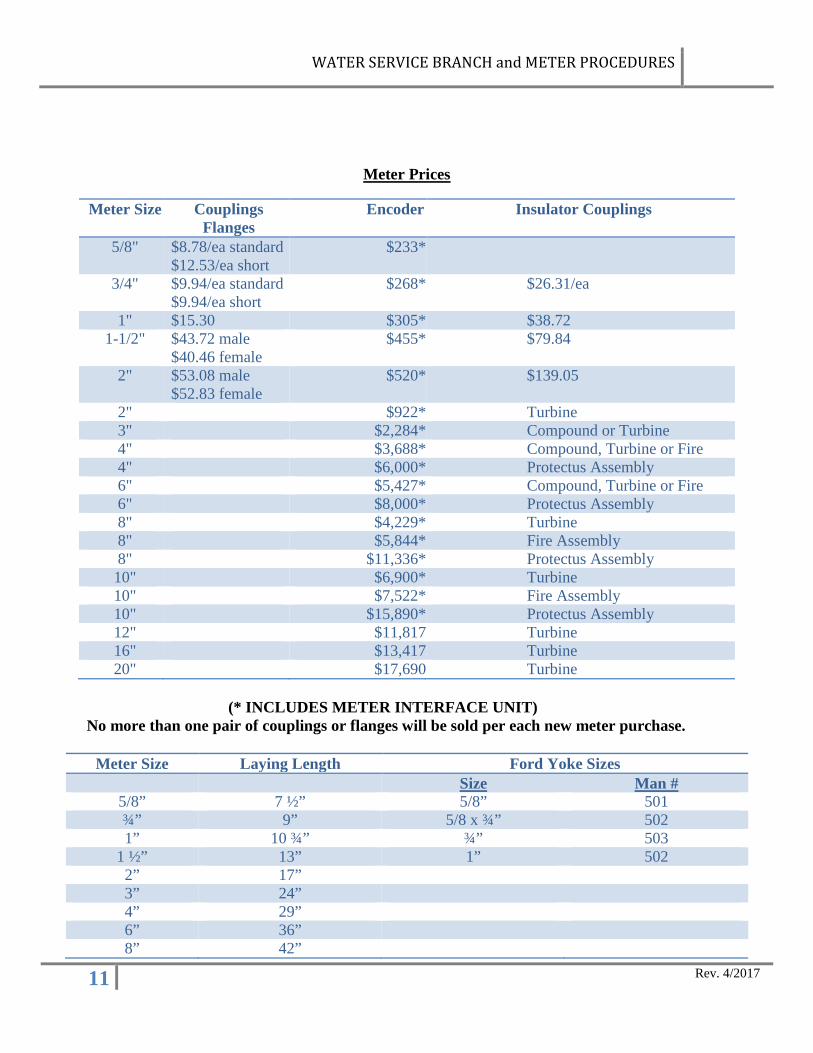
Meter Prices
Meter Size Couplings Flanges
Encoder Insulator Couplings
5/8" $8.78/ea standard $12.53/ea short
$233*
3/4" $9.94/ea standard $9.94/ea short
$268* $26.31/ea
1" $15.30 $305* $38.72 1-1/2" $43.72 male
$40.46 female $455* $79.84
2" $53.08 male $52.83 female
$520* $139.05
2" $922* Turbine 3" $2,284* Compound or Turbine 4" $3,688* Compound, Turbine or Fire 4" $6,000* Protectus Assembly 6" $5,427* Compound, Turbine or Fire 6" $8,000* Protectus Assembly 8" $4,229* Turbine 8" $5,844* Fire Assembly 8" $11,336* Protectus Assembly 10" $6,900* Turbine 10" $7,522* Fire Assembly 10" $15,890* Protectus Assembly 12" $11,817 Turbine 16" $13,417 Turbine 20" $17,690 Turbine
(* INCLUDES METER INTERFACE UNIT)
No more than one pair of couplings or flanges will be sold per each new meter purchase.
Meter Size Laying Length Ford Yoke Sizes Size Man #
5/8” 7 ½” 5/8” 501 ¾” 9” 5/8 x ¾” 502 1” 10 ¾” ¾” 503
1 ½” 13” 1” 502 2” 17” 3” 24” 4” 29” 6” 36” 8” 42”
WATER SERVICE BRANCH and METER PROCEDURES
12 Rev. 4/2017
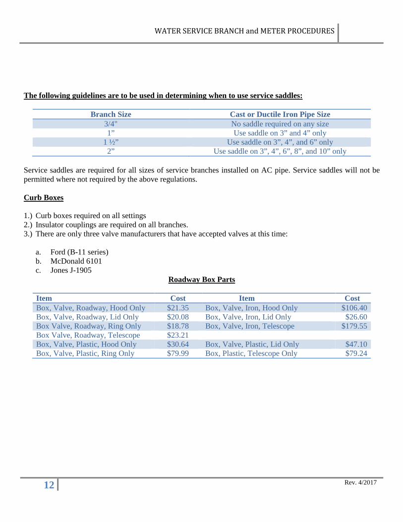
The following guidelines are to be used in determining when to use service saddles:
Branch Size Cast or Ductile Iron Pipe Size 3/4" No saddle required on any size 1” Use saddle on 3” and 4” only
1 ½” Use saddle on 3”, 4”, and 6” only 2” Use saddle on 3”, 4”, 6”, 8”, and 10” only
Service saddles are required for all sizes of service branches installed on AC pipe. Service saddles will not be permitted where not required by the above regulations. Curb Boxes 1.) Curb boxes required on all settings 2.) Insulator couplings are required on all branches. 3.) There are only three valve manufacturers that have accepted valves at this time:
a. Ford (B-11 series) b. McDonald 6101 c. Jones J-1905
Roadway Box Parts
Item Cost Item Cost Box, Valve, Roadway, Hood Only $21.35 Box, Valve, Iron, Hood Only $106.40 Box, Valve, Roadway, Lid Only $20.08 Box, Valve, Iron, Lid Only $26.60 Box Valve, Roadway, Ring Only $18.78 Box, Valve, Iron, Telescope $179.55 Box Valve, Roadway, Telescope $23.21 Box, Valve, Plastic, Hood Only $30.64 Box, Valve, Plastic, Lid Only $47.10 Box, Valve, Plastic, Ring Only $79.99 Box, Plastic, Telescope Only $79.24
WATER SERVICE BRANCH and METER PROCEDURES
13 Rev. 4/2017
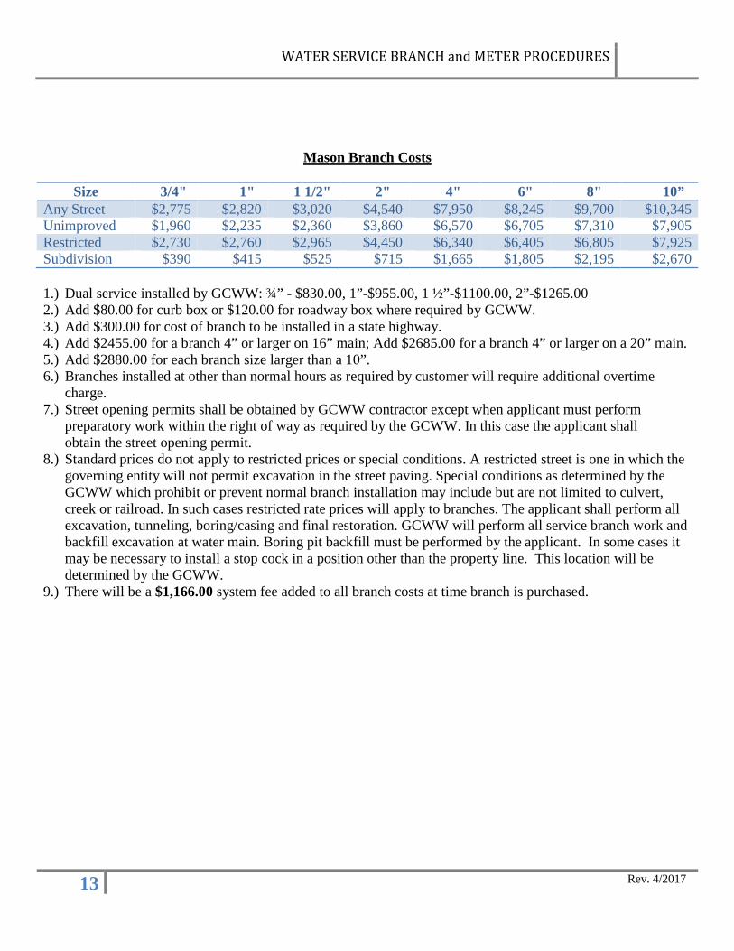
Mason Branch Costs
Size 3/4" 1" 1 1/2" 2" 4" 6" 8" 10” Any Street $2,775 $2,820 $3,020 $4,540 $7,950 $8,245 $9,700 $10,345 Unimproved $1,960 $2,235 $2,360 $3,860 $6,570 $6,705 $7,310 $7,905 Restricted $2,730 $2,760 $2,965 $4,450 $6,340 $6,405 $6,805 $7,925 Subdivision $390 $415 $525 $715 $1,665 $1,805 $2,195 $2,670 1.) Dual service installed by GCWW: ¾” - $830.00, 1”-$955.00, 1 ½”-$1100.00, 2”-$1265.00 2.) Add $80.00 for curb box or $120.00 for roadway box where required by GCWW. 3.) Add $300.00 for cost of branch to be installed in a state highway. 4.) Add $2455.00 for a branch 4” or larger on 16” main; Add $2685.00 for a branch 4” or larger on a 20” main. 5.) Add $2880.00 for each branch size larger than a 10”. 6.) Branches installed at other than normal hours as required by customer will require additional overtime
charge. 7.) Street opening permits shall be obtained by GCWW contractor except when applicant must perform
preparatory work within the right of way as required by the GCWW. In this case the applicant shall obtain the street opening permit.
8.) Standard prices do not apply to restricted prices or special conditions. A restricted street is one in which the governing entity will not permit excavation in the street paving. Special conditions as determined by the GCWW which prohibit or prevent normal branch installation may include but are not limited to culvert, creek or railroad. In such cases restricted rate prices will apply to branches. The applicant shall perform all excavation, tunneling, boring/casing and final restoration. GCWW will perform all service branch work and backfill excavation at water main. Boring pit backfill must be performed by the applicant. In some cases it may be necessary to install a stop cock in a position other than the property line. This location will be determined by the GCWW.
9.) There will be a $1,166.00 system fee added to all branch costs at time branch is purchased.
WATER SERVICE BRANCH and METER PROCEDURES
14 Rev. 4/2017
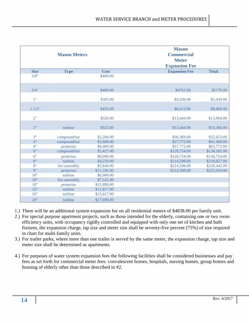
Mason Meters
Mason Commercial
Meter Expansion Fee
Size Type Cost Expansion Fee Total 5/8" $409.00
3/4" $409.00 $4761.00
$5170.00
1" $305.00 $5,030.00
$5,439.00
1 1/2" $455.00 $8,413.00
$8,868.00
2" $520.00 $13,444.00
$13,964.00
2" turbine $922.00 $13,444.00
$14,366.00
3" compound/tur $2,284.00 $30,369.00
$32,653.00 4" compound/tur $3,688.00 $57,772.00 $61,460.00 4" protectus $6,000.00 $57,772.00 $63,772.00 6" compound/tur $5,427.00 $128,754.00 $134,181.00 6" protectus $8,000.00 $128,754.00 $136,754.00 8" turbine $4,229.00 $214,598.00 $218,827.00 8" fire assembly $5,844.00 $214,598.00 $220,442.00 8" protectus $11,336.00 $214,598.00 $225,934.00
10" turbine $6,900.00 10" fire assembly $7,522.00 10" protectus $15,890.00 12" turbine $11,817.00 16" turbine $13,417.00 20" turbine $17,690.00
1.) There will be an additional system expansion fee on all residential meters of $4838.00 per family unit. 2.) For special purpose apartment projects, such as those intended for the elderly, containing one or two room
efficiency units, with occupancy rigidly controlled and equipped with only one set of kitchen and bath fixtures, the expansion charge, tap size and meter size shall be seventy-five percent (75%) of size required in chart for multi-family units.
3.) For trailer parks, where more than one trailer is served by the same meter, the expansion charge, tap size and meter size shall be determined as apartments.
4.) For purposes of water system expansion fees the following facilities shall be considered businesses and pay fees as set forth for commercial meter fees: convalescent homes, hospitals, nursing homes, group homes and housing of elderly other than those described in #2.
WATER SERVICE BRANCH and METER PROCEDURES
15 Rev. 4/2017
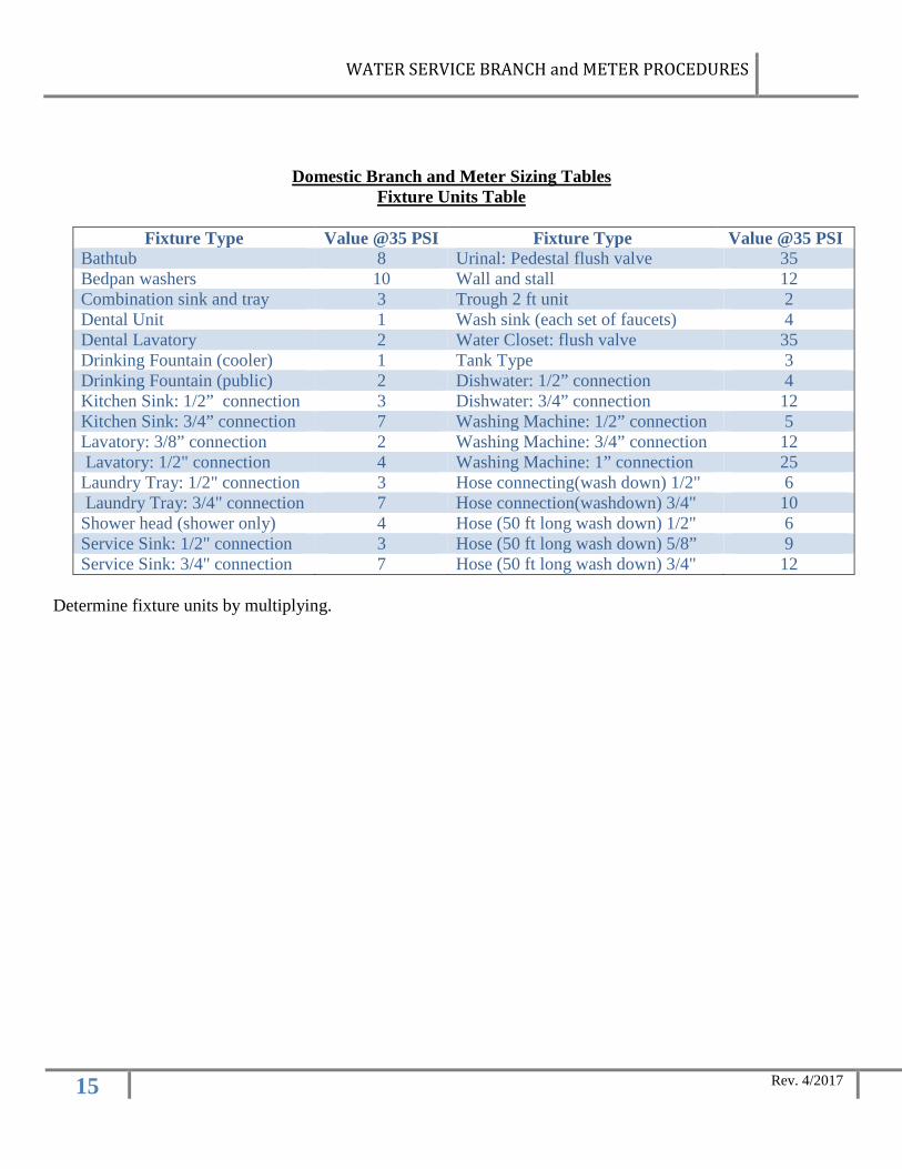
Domestic Branch and Meter Sizing Tables Fixture Units Table
Fixture Type Value @35 PSI Fixture Type Value @35 PSI
Bathtub 8 Urinal: Pedestal flush valve 35 Bedpan washers 10 Wall and stall 12 Combination sink and tray 3 Trough 2 ft unit 2 Dental Unit 1 Wash sink (each set of faucets) 4 Dental Lavatory 2 Water Closet: flush valve 35 Drinking Fountain (cooler) 1 Tank Type 3 Drinking Fountain (public) 2 Dishwater: 1/2” connection 4 Kitchen Sink: 1/2” connection 3 Dishwater: 3/4” connection 12 Kitchen Sink: 3/4” connection 7 Washing Machine: 1/2” connection 5 Lavatory: 3/8” connection 2 Washing Machine: 3/4” connection 12 Lavatory: 1/2" connection 4 Washing Machine: 1” connection 25 Laundry Tray: 1/2" connection 3 Hose connecting(wash down) 1/2" 6 Laundry Tray: 3/4" connection 7 Hose connection(washdown) 3/4" 10 Shower head (shower only) 4 Hose (50 ft long wash down) 1/2" 6 Service Sink: 1/2" connection 3 Hose (50 ft long wash down) 5/8” 9 Service Sink: 3/4" connection 7 Hose (50 ft long wash down) 3/4" 12
Determine fixture units by multiplying.
WATER SERVICE BRANCH and METER PROCEDURES
16 Rev. 4/2017
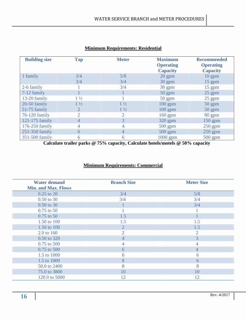
Minimum Requirements: Residential
Building size Tap Meter Maximum Operating Capacity
Recommended Operating Capacity
1 family
3/4 3/4
5/8 3/4
20 gpm 30 gpm
10 gpm 15 gpm
2-6 family 1 3/4 30 gpm 15 gpm 7-12 family 1 1 50 gpm 25 gpm 13-20 family 1 ½ 1 50 gpm 25 gpm 20-50 family 1 ½ 1 ½ 100 gpm 50 gpm 51-75 family 2 1 ½ 100 gpm 50 gpm 76-120 family 2 2 160 gpm 80 gpm 121-175 family 4 3 320 gpm 150 gpm 176-250 family 4 4 500 gpm 250 gpm 251-350 family 6 4 500 gpm 250 gpm 351-500 family 6 6 1000 gpm 500 gpm
Calculate trailer parks @ 75% capacity, Calculate hotels/motels @ 50% capacity
Minimum Requirements: Commercial
Water demand Min. and Max. Flows
Branch Size Meter Size
0.25 to 20 3/4 5/8 0.50 to 30 3/4 3/4 0.50 to 30 1 3/4 0.75 to 50 1 1 0.75 to 50 1.5 1 1.50 to 100 1.5 1.5 1.50 to 100 2 1.5 2.0 to 160 2 2 0.50 to 320 4 3 0.75 to 500 4 4 0.75 to 500 6 4 1.5 to 1000 6 6 1.5 to 1000 8 6 50.0 to 2400 8 8 75.0 to 3800 10 10 120.0 to 5000 12 12
WATER SERVICE BRANCH and METER PROCEDURES
17 Rev. 4/2017
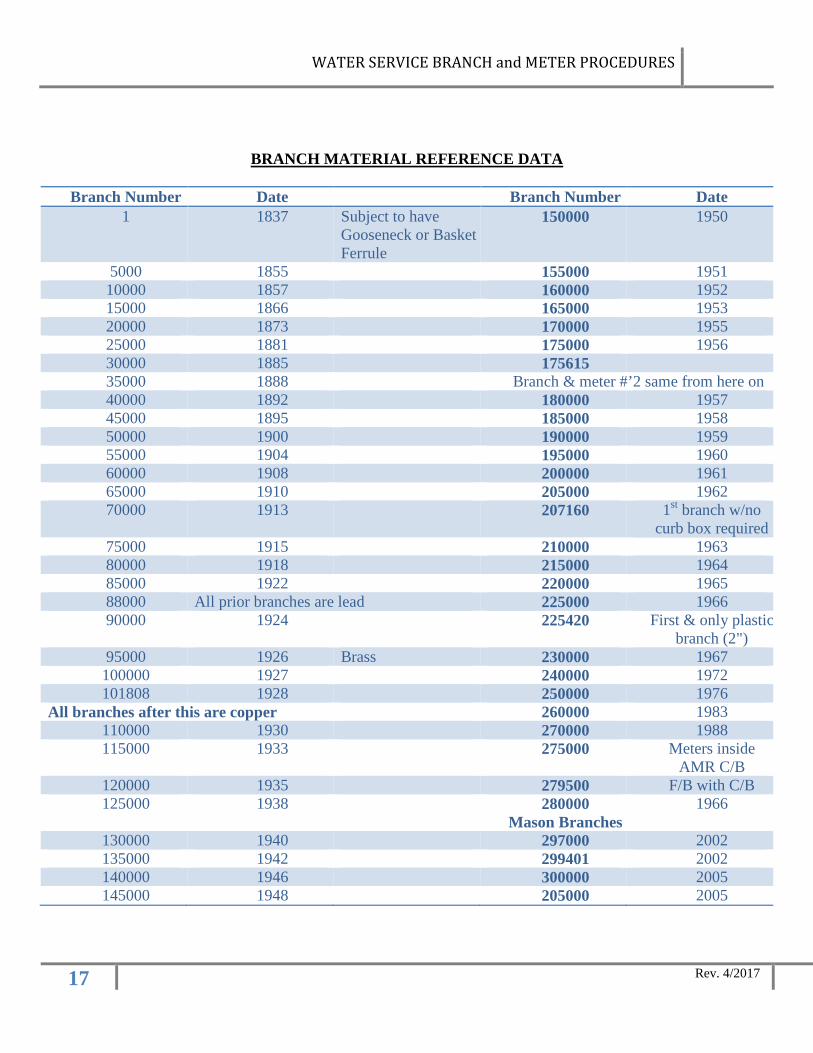
BRANCH MATERIAL REFERENCE DATA
Branch Number Date Branch Number Date 1 1837 Subject to have
Gooseneck or Basket Ferrule
150000 1950
5000 1855 155000 1951 10000 1857 160000 1952 15000 1866 165000 1953 20000 1873 170000 1955 25000 1881 175000 1956 30000 1885 175615 35000 1888 Branch & meter #’2 same from here on 40000 1892 180000 1957 45000 1895 185000 1958 50000 1900 190000 1959 55000 1904 195000 1960 60000 1908 200000 1961 65000 1910 205000 1962 70000 1913 207160 1st branch w/no
curb box required 75000 1915 210000 1963 80000 1918 215000 1964 85000 1922 220000 1965 88000 All prior branches are lead 225000 1966 90000 1924 225420 First & only plastic
branch (2") 95000 1926 Brass 230000 1967 100000 1927 240000 1972 101808 1928 250000 1976
All branches after this are copper 260000 1983 110000 1930 270000 1988 115000 1933 275000 Meters inside
AMR C/B 120000 1935 279500 F/B with C/B 125000 1938 280000
Mason Branches 1966
130000 1940 297000 2002 135000 1942 299401 2002 140000 1946 300000 2005 145000 1948 205000 2005