Water Management Linear Drainage Design Guide
18
Insitu Cast Concrete Drexus XL Concrete Drainage System Drexus XL Marshalls Drexus XL is a recycled polyethylene (PE) high capacity channel, ideally suited for high capacity heavy duty projects covering any load class from busy service yards and rail & docking ports, airports with severe dynamic transport loading to motorways and commercial outlets. The high capacity system is designed to offer attenuation and storage facilities but also to achieve sufficient flow velocities at low gradient to ensure that the channels require minimal maintenance. Drexus XL’s In-Situ surface finish is designed to integrate seamlessly into concrete surfaces. Q10 170 Drexus XL PE Former Unit www.marshalls.co.uk/commercial/water-management Linear Drainage Design Guide Drexus XL Linear Drainage
Transcript of Water Management Linear Drainage Design Guide
InsituCast Concrete
Drexus XL Concrete Drainage System
Drexus XL
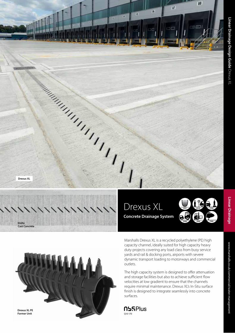
Marshalls Drexus XL is a recycled polyethylene (PE) high capacity channel, ideally suited for high capacity heavy duty projects covering any load class from busy service yards and rail & docking ports, airports with severe dynamic transport loading to motorways and commercial outlets.
The high capacity system is designed to offer attenuation and storage facilities but also to achieve sufficient flow velocities at low gradient to ensure that the channels require minimal maintenance. Drexus XL’s In-Situ surface finish is designed to integrate seamlessly into concrete surfaces.
Q10 170Drexus XL PE Former Unit
Linear Channel
200
ww
w.m
arshalls.co.uk/comm
ercial/water-m
anagement
Water M
anagement
ww
w.m
arshalls.co.uk/comm
ercial/water-m
anagement
Linear Drainage D
esign Guide D
rexus XLLinear D
rainage

Drexus XL
Linear Drainage D
esign Guide D
rexus XL Introductionw
ww
.marshalls.co.uk/com
mercial/w
ater-managem
ent
Linear Drainage Design Guide
Linear Drainage
One of the highest flow capacity system on the market
Reduced post-installation maintenance
Extensive applications
Robust system
Complies with BS EN 1433:2002
Sufficient flow velocities can be achieved at low gradient to
promote self cleansing
Straightforward to install
5 different channel depths
High attenuation capacity
Simple detailing
Channel and kerb applications
One-piece channel design with quick and easy installation
Concrete Drainage System
Marshalls Drexus XL is a recycled polyethene (PE) high capacity channel system. It’s innovative inlet ‘fin’ design maximises strength at the surface enabling this one piece system to site at surface level without the need for a secondary rail system which helps reduce the cost of installation.
The Drexus XL have been designed with attenuation in mind and will assist with site wide storage becoming an integral part of any sustainable surface water management solution as part of either a SUDS or traditional drainage system.
It is ideally suited for high capacity heavy duty projects covering any load class from busy service yards and rail & docking ports, airports with severe dynamic transport loading to motorways and commercial outlets.
The high capacity system is designed to offer attenuation and storage facilities but also to achieve sufficient flow velocities at low gradient to ensure that the channels require minimal maintenance. Drexus XL’s In-Situ surface finish is designed to integrate seamlessly into concrete surfaces.
Slot cap protectors provided for an easy
surface finish upon install
V-shaped channel improves the speed of water providing self cleansing
Female and male connection to provide ease
and speed of installation
Sealant ring is provided for an easy water tight installation
Certified to D400 loading BS EN 1433:2002
Divergent inlet apertures for ease of maintenance
Channel is available in 2m lengths to reduce time of installation on site
Apertures positioned at 45° for greater inlet capacity
Apertures spaced adequately to allow rebar constructions
Wing fastenings provide a secure and strong connection to adjacent channels
Channel design to provide strength and key the haunch to the channel providing a rigid install
3 v-grooved feet to aid with levelling and pinning to the groundwork

Linear Channel
202
ww
w.m
arshalls.co.uk/comm
ercial/water-m
anagement
Water M
anagement
ww
w.m
arshalls.co.uk/comm
ercial/water-m
anagement
Linear Drainage D
esign Guide D
rexus XL Components
Linear Drainage
Components
CHANNELS
325 Channel 425 Channel 525 Channel 675 Channel 825 Channel
Access & Outlet Units• The Access Chambers modular design provides rodding access or outfall
and silt trap abilities.
• Each face of the Access Chamber features cutting guides for a series of channel depths allowing multiple connections of differing size channels acting as a junction or interim access point for maintenance.
• F900 rated Access Cover and Frames features a unique patented quick and easy locking and unlocking mechanism for ease of maintenance.
Chamber Connector• Provides a connection from the Channel to the Access Chamber
• Available in both Female and Male options to allow either end of Channel to connect into the Access Chamber.
Transition Units• 4 different sizes transition units provides uninterrupted flow between
the Channels minimizing impact on the hydraulic performance.
• Designed to provide the system with flow control and attenuation capabilities.
End Caps & Cap Outlets • End caps are designed to be universal to be used for both the Female or
Male ends of the Channel.
• Cap Outlets enable the system to connect to standard underground pipes.
ACCESSORIES
Chamber Connector 425 Female
Access Cover & Frame
Access Chamber
Silt Box
Transition Unit 425-525 Female to Male
End Cap
Chamber Connector 425 Male
Transition Unit 425-525 Male to Female

Drexus XL
ref. d i u W325 585 505 294 300
425 741 648 437 489
525 831 738 528 543
675 971 878 667 644
825 1128 1036 852 751
Linear D
rainag
e Design
Guid
e Drexus XL Standard D
etailswww.m
arshalls.co.uk/commercial/w
ater-managem
ent
Linear Drainage Design Guide
Linear D
rainag
e
204
Components
DREXUS XL BASE
Drexus XL325
Birco 150 with 825
Drexus XL675
Drexus XL525
Drexus XL425
Equivalent PipeDiameter (mm) 675
Equivalent PipeDiameter (mm) 550
Equivalent PipeDiameter (mm) 435
Equivalent PipeDiameter (mm) 360
Equivalent PipeDiameter (mm) 225
Drexus XL
ref. d i u W
325 585 505 294 300
425 741 648 437 489
525 831 738 528 543
675 971 878 667 644
825 1128 1036 852 751
300
294
505
585
300
294
505
585
489
437
648
741
543
528
738
831
644
667
878
971
751
825 10
36
1128
Linear Drainage D
esign Guide D
rexus XL Hydraulic D
ataw
ww
.marshalls.co.uk/com
mercial/w
ater-managem
ent
Linear Drainage Design Guide
Linear Drainage
Hydraulic Data
FLOW CAPACITY
Drexus XL325
Birco 150 with 825
Drexus XL675
Drexus XL525
Drexus XL425
Equivalent PipeDiameter (mm) 675
Equivalent PipeDiameter (mm) 550
Equivalent PipeDiameter (mm) 435
Equivalent PipeDiameter (mm) 360
Equivalent PipeDiameter (mm) 225
Linear D
rainag
e Design
Guid
e Drexus XL Standard D
etailswww.m
arshalls.co.uk/commercial/w
ater-managem
ent
Linear Drainage Design Guide
Linear D
rainag
e
204
Components
DREXUS XL BASE
Drexus XL325
Birco 150 with 825
Drexus XL675
Drexus XL525
Drexus XL425
Equivalent PipeDiameter (mm) 675
Equivalent PipeDiameter (mm) 550
Equivalent PipeDiameter (mm) 435
Equivalent PipeDiameter (mm) 360
Equivalent PipeDiameter (mm) 225
Drexus XL
ref. d i u W
325 585 505 294 300
425 741 648 437 489
525 831 738 528 543
675 971 878 667 644
825 1128 1036 852 751
300
294
505
585
300
294
505
585
489
437
648
741
543
528
738
831
644
667
878
971
751
825 10
36
1128
Linear D
rainag
e Design
Guid
e Drexus XL Standard D
etailswww.m
arshalls.co.uk/commercial/w
ater-managem
ent
Linear Drainage Design Guide
Linear D
rainag
e
204
Components
DREXUS XL BASE
Drexus XL325
Birco 150 with 825
Drexus XL675
Drexus XL525
Drexus XL425
Equivalent PipeDiameter (mm) 675
Equivalent PipeDiameter (mm) 550
Equivalent PipeDiameter (mm) 435
Equivalent PipeDiameter (mm) 360
Equivalent PipeDiameter (mm) 225
Drexus XL
ref. d i u W
325 585 505 294 300
425 741 648 437 489
525 831 738 528 543
675 971 878 667 644
825 1128 1036 852 751
300
294
505
585
300
294
505
585
489
437
648
741
543
528
738
831
644
667
878
971
751
825 10
36
1128
Linear Channel
204
ww
w.m
arshalls.co.uk/comm
ercial/water-m
anagement
Water M
anagement
ww
w.m
arshalls.co.uk/comm
ercial/water-m
anagement
Linear Drainage D
esign Guide D
rexus XL Hydraulic D
ataLinear D
rainage
Hydraulic Data
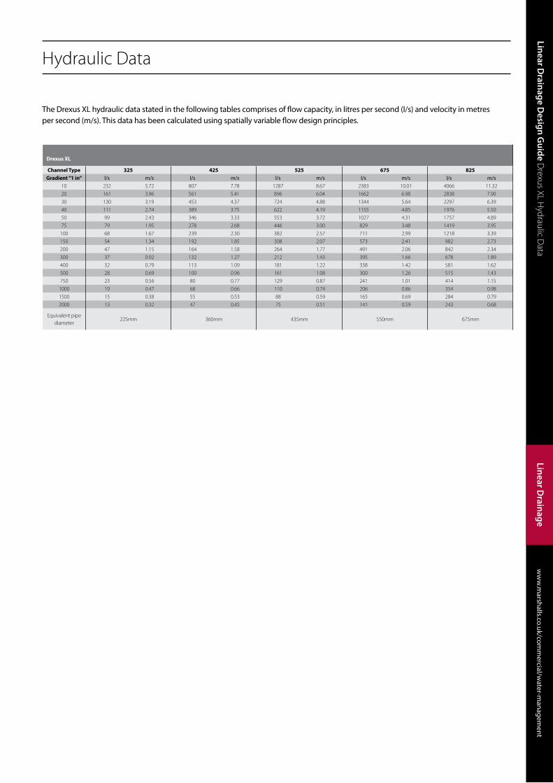
The Drexus XL hydraulic data stated in the following tables comprises of flow capacity, in litres per second (l/s) and velocity in metres per second (m/s). This data has been calculated using spatially variable flow design principles.
Drexus XL
Channel Type 325 425 525 675 825Gradient "1 in" l/s m/s l/s m/s l/s m/s l/s m/s l/s m/s
10 232 5.72 807 7.78 1287 8.67 2383 10.01 4066 11.32
20 161 3.96 561 5.41 896 6.04 1662 6.98 2838 7.90
30 130 3.19 453 4.37 724 4.88 1344 5.64 2297 6.39
40 111 2.74 389 3.75 622 4.19 1155 4.85 1976 5.50
50 99 2.43 346 3.33 553 3.72 1027 4.31 1757 4.89
75 79 1.95 278 2.68 446 3.00 829 3.48 1419 3.95
100 68 1.67 239 2.30 382 2.57 711 2.99 1218 3.39
150 54 1.34 192 1.85 308 2.07 573 2.41 982 2.73
200 47 1.15 164 1.58 264 1.77 491 2.06 842 2.34
300 37 0.92 132 1.27 212 1.43 395 1.66 678 1.89
400 32 0.79 113 1.09 181 1.22 338 1.42 581 1.62
500 28 0.69 100 0.96 161 1.08 300 1.26 515 1.43
750 23 0.56 80 0.77 129 0.87 241 1.01 414 1.15
1000 19 0.47 68 0.66 110 0.74 206 0.86 354 0.98
1500 15 0.38 55 0.53 88 0.59 165 0.69 284 0.79
2000 13 0.32 47 0.45 75 0.51 141 0.59 243 0.68
Equivalent pipe diameter
225mm 360mm 435mm 550mm 675mm

Linear Drainage D
esign Guide D
rexus XL Component Codes
ww
w.m
arshalls.co.uk/comm
ercial/water-m
anagement
Linear Drainage Design Guide
Linear Drainage
Drexus XL Channel Component Codes
Constant DepthChannel
LoadingLength (mm)
Width (mm)
InvertWidth (mm)
Depth (mm)
Invert Depth (mm)
Unit Weight (kg)
In-situ Top
325 B125 - F900 2000 300 188 585 505 13 DR537010425 B125 - F900 2000 483 319 723 648 20 DR537020525 B125 - F900 2000 543 379 813 738 23 DR537030675 B125 - F900 2000 644 482 949 878 27 DR537040825 B125 - F900 2000 707 586 1106 1036 32 DR537050
A
B
C
Drexus XL with reference numbers indicated in bold black are available ex-stock.Drexus XL with reference numbers indicated in light are manufactured to order.Contact our sales office to discuss your requrements.
Constant Depth Channel
Transition Channels
Transition ChannelsLength (mm)
Width (mm)
InvertWidth (mm)
Depth (mm)
Invert Depth (mm)
Unit Weight (kg)
In-situ Top
425-325 F-M 478 489/300 322/214 542/348 463/292 3.25 DR538110525-425 F-M 478 543/489 379/322 592/542 527/463 4.5 DR538120675-525 F-M 478 644/543 476/379 732/592 664/527 5.8 DR538130825-675 F-M 478 706/644 582/476 890/732 821/664 7.5 DR538140325-425 M-F 478 300/489 214/322 348/542 292/463 3.5 DR538010425-525 M-F 478 543/489 322/379 542/592 463/527 4.6 DR538020525-675 M-F 478 543/644 379/476 592/732 527/664 5.9 DR538030675-825 M-F 478 644/706 476/582 732/890 664/821 7.6 DR538040

Linear Channel
206
ww
w.m
arshalls.co.uk/comm
ercial/water-m
anagement
Water M
anagement
ww
w.m
arshalls.co.uk/comm
ercial/water-m
anagement
Linear Drainage D
esign Guide D
rexus XL Component Codes
Linear Drainage
Outfall AccessoriesUnit Weight (kg)
Item Code
325 AC Connector - M 2.6 DR538410425 AC Connector - M 3.9 DR538420525 AC Connector - M 5 DR538430675 AC Connector - M 7 DR538440825 AC Connector - M 9 DR538450325 AC Connector - F 2.5 DR538510425 AC Connector - F 3.9 DR538520525 AC Connector - F 4.9 DR538530675 AC Connector - F 6.9 DR538540825 AC Connector - F 9 DR538550325 - 525 Access Chamber 11.5 DR538905675 - 825 Access Chamber 15 DR538920Universal Access Cover F900 159 DR538930Universal Silt Chamber 8.5 DR538915
A
B
D
DD
Outfalls Accessories
End Cap/Cap OutletsUnit Weight (kg)
Item Code
325 End Cap 1 DR537910425 End Cap 2.5 DR537920525 End Cap 3 DR537930675 End Cap 4.5 DR537940825 End Cap 5.5 DR537950325 Cap Outlet - M 1.9 DR537955425 Cap Outlet - M 3.1 DR537956525 Cap Outlet - M 4.2 DR537957675 Cap Outlet - M 5.8 DR537958825 Cap Outlet - M 9.4 DR537959325 Cap Outlet - F 2.0 DR537960425 Cap Outlet - F 3.3 DR537961525 Cap Outlet - F 4.4 DR537962675 Cap Outlet - F 6.0 DR537963825 Cap Outlet - F 9.7 DR537964
C End Cap/Cap Outlets

Linear Drainage D
esign Guide D
rexus XL Standard Details
ww
w.m
arshalls.co.uk/comm
ercial/water-m
anagement
Linear Drainage Design Guide
Linear Drainage
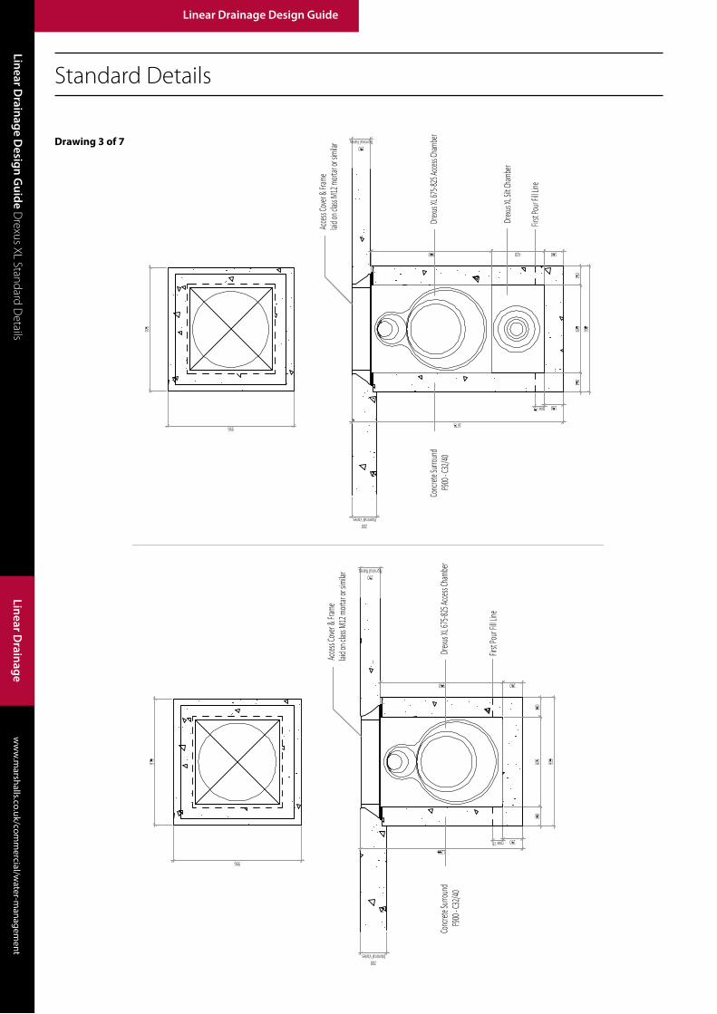
Standard Details
Drawing 1 of 7
Linear Channel
208
ww
w.m
arshalls.co.uk/comm
ercial/water-m
anagement
Water M
anagement
ww
w.m
arshalls.co.uk/comm
ercial/water-m
anagement
Linear Drainage D
esign Guide D
rexus XL Standard Details
Linear Drainage
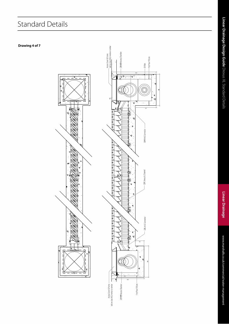
Standard Details
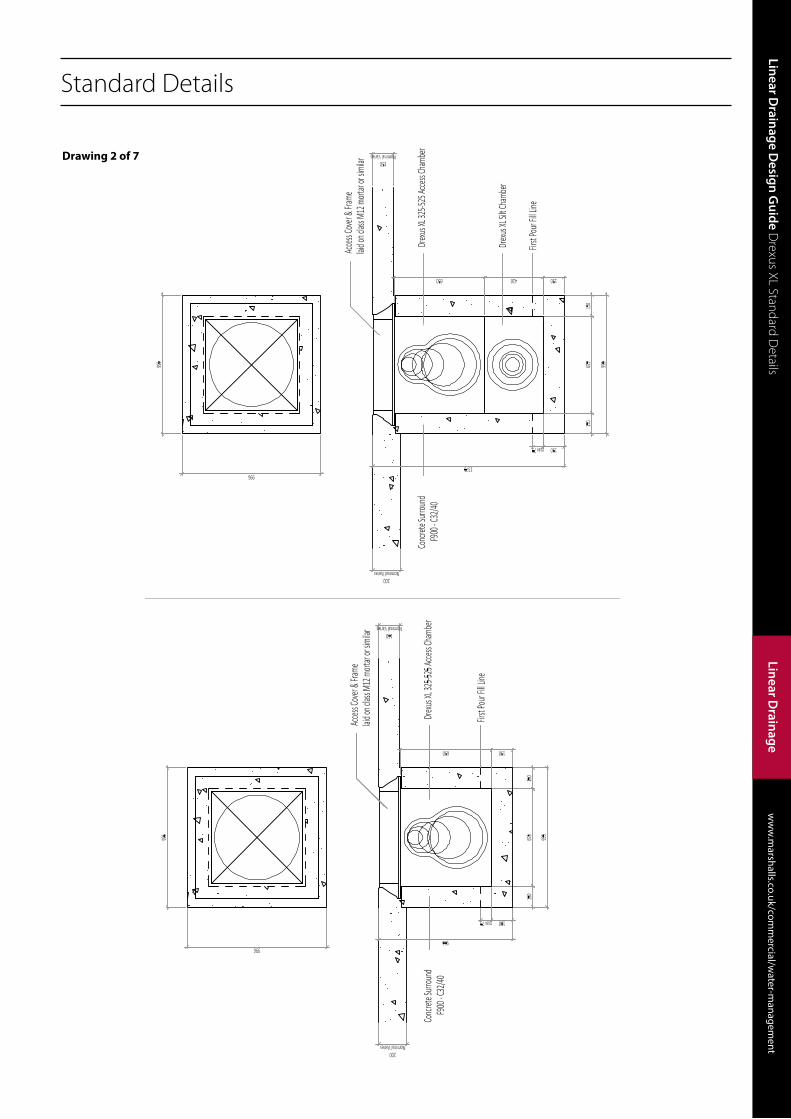
Drawing 2 of 7
Linear Drainage D
esign Guide D
rexus XL Standard Details
ww
w.m
arshalls.co.uk/comm
ercial/water-m
anagement
Linear Drainage Design Guide
Linear Drainage
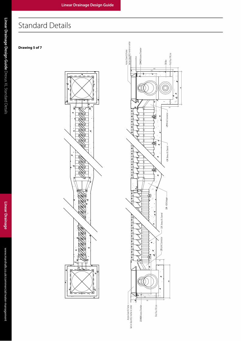
Standard Details
Drawing 3 of 7
Linear Channel
210
ww
w.m
arshalls.co.uk/comm
ercial/water-m
anagement
Water M
anagement
ww
w.m
arshalls.co.uk/comm
ercial/water-m
anagement
Linear Drainage D
esign Guide D
rexus XL Standard Details
Linear Drainage
Standard Details
Drawing 4 of 7
Linear Drainage D
esign Guide D
rexus XL Standard Details
ww
w.m
arshalls.co.uk/comm
ercial/water-m
anagement
Linear Drainage Design Guide
Linear Drainage
Standard Details
Drawing 5 of 7

Linear Channel
212
ww
w.m
arshalls.co.uk/comm
ercial/water-m
anagement
Water M
anagement
ww
w.m
arshalls.co.uk/comm
ercial/water-m
anagement
Linear Drainage D
esign Guide D
rexus XL Standard Details
Linear Drainage
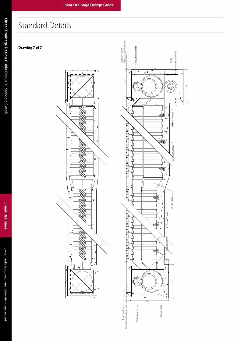
Standard Details
Drawing 6 of 7
Linear Drainage D
esign Guide D
rexus XL Standard Details
ww
w.m
arshalls.co.uk/comm
ercial/water-m
anagement
Linear Drainage Design Guide
Linear Drainage
Standard Details
Drawing 7 of 7

Linear Channel
214
ww
w.m
arshalls.co.uk/comm
ercial/water-m
anagement
Water M
anagement
ww
w.m
arshalls.co.uk/comm
ercial/water-m
anagement
Linear Drainage D
esign Guide D
rexus XL Standard Details
Linear Drainage
Standard Details Specification
Notes for Drexus XL
Drawings 1 to 7
1. All dimensions are in millimetres
2. 5 mm Allowance made for pavement settlement
3. Mortar shall be Class 12 to BS EN 988-2:2003
4. Reinforcement shall have a minimum 60 mm cover unless otherwise
stated by the Engineer
5. The standard details show the general arrangements used by Marshalls
for product evaluation and load test classification purposes which may
differ from customer requirements and site conditions. Reinforcement
and concrete surrounds should be checked and accepted by the
Engineer for project use
Introduction
The following specification covers the complete Drexus XL system including
ancillary fittings and is compatible with the standard detail drawings.
Where the Manual of Contract Drawings for Highways Works is used,
information for ‘Appendix 5/6: Linear Channels’.
Drexus XLDrexus XL has PE channel which is surrounded in concrete to form a high
capacity linear drainage system. The system is a constant depth channel and
is laid flush with the pavement surface. The system reference number relates
to the channel depth.
1. The linear drainage system shall be Drexus XL manufactured and
supplied by Marshalls plc. All channel materials and ancillary products
detailed in this specification shall be supplied by Marshalls.
2. All components of the system shall be type tested and be fully
compliant with the requirements of BS EN 1433:2002: Drainage
channels for vehicular and pedestrian areas – Classification, design and
testing requirements, marking and evaluation of conformity’ when
installed as per manufacturers recommendations.
3. The linear drainage system shall be a one-piece unit manufactured in a
single material (Density Polyethylene PE) with the exception of certain
ancillary products as supplied by the manufacturers in accordance with
standard details.
4. The linear drainage channel:-
i. Shall be of a constant depth between transitions or access points
ii. Shall have a 3:2 ratio egg shape cross section as described in HR
Wallingford: Tables for the hydraulic design of pipes, sewers and
channels: 6th Edition: Vol 1
iii. Shall have multiple slot openings set at a transverse angle of 45° to
the length of the channel and each slot shall be 150 mm in overall
length, 10 mm wide and have an end radius of 5 mm
iv. Shall have a minimum inlet area of 13,800 mm2/m
v. When installed shall have slot openings set below the final pavement
surface
vi. Shall fully comply with the requirements of ‘BS EN 13501-
1:2007+A1:2009: cl (8) & (9): Fire classification of construction
products and building elements. Classification using test data from
reaction to fire tests’.
5. The linear drainage shall be installed to line and level indicated in
the contract and in accordance with manufacturer’s instructions and
standard details.
6. The drainage system shall be installed in accordance with
manufacturers recommendations, industry best practice or as detailed
in the contract / WRc Sewers for Adoption; 7th Edition : 2012 / BS EN 752:2008 / BS 8000: Part 14:1989*
Note: * delete as required
Linear Drainage D
esign Guide D
rexus XL Constructionw
ww
.marshalls.co.uk/com
mercial/w
ater-managem
ent
Linear Drainage Design Guide
Linear Drainage
Introduction
Installation of the Drexus XL linear drainage system should be carried out in
accordance with Marshall’s specification and standard detail.
The following method of installation is recommended by Marshalls and it
is based on conventional UK best practice construction techniques and
installation and testing trials and if applicable, installation shall comply with
the recommendations in the Construction Phase Plan as defined by the
‘Construction (Design and Management) Regulations 2015’.
Should your application differ from standard installation guidance you
should consult with your Engineer or Marshalls Technical Advice Team.
Excavation
1. Sufficient material should be excavated to accommodate the channel unit, concrete bed and haunch and working areas.
2. Place excavation support as required depending on channel size, native ground conditions and method of working. Any ‘soft spots’ or poorly compacted formation should be made good.
Setting Out
1. Setting out pins should be accurately located in accordance with the contract drawings, with a string line level with the top and end of the channel slots. Pins should be located to avoid having to lift the channel units over the string line. The slots should be set so as to follow the longfall and crossfall of the final surface as required by the contract drawings.
2. Alternatively, a pipe laser placed at surface level may be used. It is not recommended that line and level is set using internal channel faces.
3. Line and level should be checked at regular intervals and channels adjusted as required. Marshalls recommend as a minimum that line and level are checked at the end of each concrete pour and before initial set has taken place.
Site Storage, Handling and Placing
1. Marshalls recommend that units are stored in their original packaging until required to help reduce the risk of damage and to help with movement around site.
2. It is the site contractor’s responsibility to ensure that units are stored on solid level ground and in a clean and protected area away from potential site damage. Care should be taken when removing units from secure packaging and pallets and units should not be stacked more than one pallet high. Units shall not be stored close to sources of heat such as engine exhaust outlets or hot works areas such as welding and cutting.
3. Should the units be put in long term storage Marshalls recommend that the units are covered to protect mating surfaces and slot opening from dirt and debris until such time that they are required. Additional protection may be required to prevent accidental damage.
4. Marshalls advise that all drainage components should be installed by a safe method of working. The use of mechanical handling equipment such as lifting strops have proven to be of benefit and will eliminate manual handling. Whilst the smaller units are relatively light in weight, Marshall’s do not recommend manual handling due to the size and shape of units.
Outfalls
1. Outfalls are formed using the Marshalls plastic outfall chamber and silt box units as required. The small access chamber is suitable for the channel unit up to size 525, the large access chamber is suitable for channel units 675 & 825.
2. The access chamber shall be cut to accept a chamber connector using the preformed template as a guide. The outfall chamber shall be bedded on semi-dry concrete (class S1) and concrete surround formed as per the standard details. The top surface of the surround shall finish flush with the top surface of the chamber. Provision should be made for the chamber connector to be cast monolithically in to the concrete surround or placed during installation of the channel units.
3. If a silt trap is required, it can be placed below the access chamber and the chamber base can be cut and removed using the preformed circular template as a guide. The silt box can be rotated to any orientation to receive the outlet pipe. For the best results and to maintain a watertight connection between the silt box and chamber, the concrete surround shall be cast monolithically. Depending on the method of installation the chamber may require bracing or support to avoid movement during the placement of concrete.
4. Access chambers shall have cast iron access covers and frames load rated to their intended application and shall be bedded and haunched on class 12 mortar (or as specified in the contract). When placed correctly, the frame will sit centrally over the chamber opening and directly on the concrete surround. The cover and frame can be placed after the concrete has
Channel Units
1. Drexus XL units are installed using the same principles of conventional pipe laying techniques.
2. Starting at the outfall chamber, i.e. working uphill, Marshalls recommend the following installation technique:-
3. Place the concrete bed to the correct line and level allowing the channel units to be placed on to the upper surface.
4. Place the chamber connector and first unit to the chamber. Minor adjustment to line and level can be made by placing non-compressible wedges beneath the feet. Subsequent channels are placed end to end in the same manner.
5. Units should be connected (or jointed) together using a mechanical pipe puller to form the joint and a propriety pipe lubricant may be used to aid jointing operations as required. Do not use soaps, grease or oils which are not designed for use with flexible pipe jointing gaskets.
6. Marshalls recommend the use of full channels and do not recommend cutting or alteration of channels and designs are be produced to accommodate full lengths with ancillaries.
7. To maintain water tightness, channels shall be sealed at each joint using Marshall’s flexible rubber pipe seal and adjacent channels shall be connected at each connection tab with cable ties, a peg, a nut and bolt or similar to maintain the integrity of each drainage run during installation runs.
8. Channels shall be regularly checked and adjusted for line and level and where channel units do no terminate in an access chamber, end caps shall be use to seal the drainage run.
Concrete bed and surround
1. Marshalls recommend a multi-layered pour sequence to avoid movement during placement of the concrete surround (see standard details). However, depending on the method of working, the size of the channel, the workability class of the concrete, the thickness of the surround and the size of the excavation, the channels may require additional support to avoid movement of the units or may require the use of temporary formwork to form the concrete surround to the correct size for each channel unit. The concrete thickness shall be as the minimum stated in the standard detail for each load class.
2. To help maintain channel alignment during the placement of the concrete bed and surround, channels can be secured in position with ‘pins’ or ‘U’ bars using the ‘V’ notch in the feet of each channel; retaining straps over the units fixed to the base concrete; kentilage or timber props.
3. Place and compact semi-dry concrete (class S1) to form base and to anchor the unit in position and avoid the risk of flotation. Check line and level and adjust to suit and ensure no voids are present to maintain load bearing strength. Refer to Marshalls Specification for concrete grades and depths. Allow a minimum 12 hrs to allow the concrete base to achieve an acceptable working strength before subsequent concrete is placed.
4. Place and compact the semi-dry concrete surround (class S1) in layers not exceed 150 mm on alternating sides of the channel to avoid movement and deformation. Check line and level, adjust to suit and ensure no voids are present to maintain load bearing capacity. The top surface shall be
Construction
Linear Channel
216
ww
w.m
arshalls.co.uk/comm
ercial/water-m
anagement
Water M
anagement
ww
w.m
arshalls.co.uk/comm
ercial/water-m
anagement
Linear Drainage D
esign Guide D
rexus XL ConstructionLinear D
rainage
Construction
no greater than the underside of the final surface pavement. Allow a minimum 12 hrs to allow the concrete surround to achieve an acceptable initial strength before subsequent concrete is placed.
5. If the channel is to be backfilled before placement of the final surface pavement, a minimum of 72 hrs shall pass before removal of formwork and backfilling commences. Care shall be taken during backfilling operations not to traffic or place loads on the channel surround.
6. The pipes may be used for the transportation of water when the concrete surround and backfill is up to the underside of the final pavement level and following a minimum of 72 hrs after installation.
Concrete pavement (final surface)
1. Place and compact final pavement concrete (class S2) to form final surface. Ensure plastic slot bungs are in place to prevent concrete ingress. If there are no specific Engineers specification, refer to Marshalls Specification for concrete grades, depths and reinforcement requirements.
2. The final surface shall be finished using float or beam to the required texture and the flat slot top shall provide a reference level for the final upper surface. The Customer may decide to change the shape and nature of the final pavement subject to their design and installation preferences. Specialist engineering advice may be required.
Reinforcement
1. Marshalls recommend the use of reinforcement for certain channel sizes and particular load classes.
2. If required, steel reinforcement shall be placed and spaced using non-compressible pcc setting blocks and tied using mild steel tie wire and shall be generally installed as conventional UK best practice. Refer to Marshalls standard specification for the typical arrangement for each application.
3. Final surface pavement only - Straight lacer bars shall be placed parallel over the channel body between the slot fins and spaced and tied to the main longitudinal steel or mesh to form a composite reinforcement mat.
4. Upper and side reinforcement – ‘L’ bars shall be placed parallel over the channel body between the slot fins. One leg shall be placed in the horizontal position and one leg shall be placed vertically down the side of the channel body. They shall be spaced and tied to the longitudinal main steel to form a composite steel cage.
5. Base reinforcement – for extreme load classes, base reinforcement is required which may be a structural mesh sheet placed and spaced using pcc setting blocks.
6. Concrete shall be placed so as not to damage the reinforcement. Dependant on the workability class concrete shall be vibrated or carefully placed so as to ensure full compaction and encasement of reinforcement to eliminate voids and maintain structural capacity. Consideration shall be given to the sequence of installation for reinforcement and placement of concrete.
7. The standard details show the general arrangements used by Marshalls for product evaluation and load test classification purposes which may differ from customer requirements and site conditions. The Customer may decide to change the reinforcement requirements subject to their installation preferences and ground conditions and specialist engineering advice may be required.
Expansion joints
1. Make provision for transverse expansion joints at the same frequency as adjacent concrete bays. If the drainage run is to be isolated from adjacent in-situ concrete slabs, then full depth contraction joints across the channel should be formed at between 5 and 8 metre centres. Movement joints parallel to the channel run should be formed either side of the channel surround to the full depth of the adjacent concrete slab and the joint should be designed to fully isolate the channel from any movement of the structural slab. Similarly, access chambers should also be isolated from the adjacent structural concrete slab by incorporating movement joints around the access chamber.
2. The design of the structural concrete slab and flexible joint with regard to the introduction of crack inducers, bay size and movement joint sealants is by others and specialist engineering advice may be required.
Commissioning
1. Do not load or traffic over the channel until the concrete has fully cured and reached full strength.
2. If the strength is unknown, then this should be a minimum 28 days. Loading or trafficking the channel before 28 days has lapsed, concrete strength should be confirmed by a concrete strength test. Particular care should be taken during the construction phase when load conditions may be more onerous due to construction plant and machinery movements and/or incomplete construction.
3. When the pavement has cured sufficiently to allow careful foot traffic (approx 48hrs), the slot bungs can be struck and removed or struck and left in place to avoid site debris entering the channel. The slots can be removed with a hooked or pointed tool (such as a bladed screwdriver or pry bar) by piercing the top surface. Move the tool from side to side before levering out in the direction of the slot length. The slot opening is designed such that on removal of the bung, the final pavement forms the lip of the slot opening. No plastic slot should be exposed at the upper surface level.
Notes
1. In order to obtain a good line and level, it is important to follow the installation guidance and check frequently as concrete is laid. The slot bungs provide a reference for the final surface level.
2. It is not recommended that channels are cut to length on site, drainage runs will be calculated and supplied to multiples of whole units with ancillaries.
3. Outfalls, access chambers and silt traps shall be constructed in accordance with the Standard Details. Silt traps and access chambers should be located at no more than 50m centres in long runs.
4. To help avoid the chamber and silt box units moving out of alignment during installation, screws can be fixed through the chamber base. To help avoid deformation of the chamber sides during placement of the concrete surround, internal cross bracing may be used.
5. Access chambers have been designed to be non-man entry.
6. Installation operations should be discontinued if weather conditions are such that the performance of the channel system may be compromised. Installation should not be undertaken when the temperature is below 3ºC on a falling thermometer or below 1ºC on a rising thermometer.
7. Concrete strengths, dimensions and reinforcement details indicated on typical arrangement drawings were determined to undertake product evaluation, installation and load testing trials to fully comply with BS EN 1433:2002 (Drainage channels for vehicular and pedestrian areas). These may vary to actual site conditions and specialist engineering advice may be required especially in unusual ground or load conditions.
8. Concrete base and surrounds have been designed to be semi-dry (class S1) to allow the units to be adjusted to maintain line and level and to avoid movement during installation.
9. Concrete chemical exposure class shall be determine by the Engineer.
10. All necessary Personal Protective Equipment (PPE) should be worn on site, as site rules stipulate. Goggles, ear defenders, dust masks and protective footwear must always be worn whenever cutting operations are undertaken.
11. COSHH - All relevant health and safety information, including COSHH data sheets, can be obtained from Marshalls Advisory Services, or the Marshalls Design Team on 0845 3020606.

Linear Drainage D
esign Guide D
rexus XLw
ww
.marshalls.co.uk/com
mercial/w
ater-managem
entLinear D
rainage