WATER & WASTEWATER UTILITY STANDARDS -
239
DEPARTMENT OF UTILITY SERVICES WATER, WASTEWATER & RECLAIMED WATER Utility Construction Standards March 13, 2018 Supersedes all previous versions
Transcript of WATER & WASTEWATER UTILITY STANDARDS -

DEPARTMENT OF UTILITY SERVICES
WATER, WASTEWATER
& RECLAIMED WATERUtility Construction Standards
March 13, 2018
Supersedes all previous versions

TABLE OF CONTENTS
I. GENERAL II. DETAIL DRAWINGS
DRAWING NUMBER AND TITLES
W-1 Fire Hydrant and Valves (Location Detail) W-2 Fire Hydrant Details W-3 Manual 2” Blow-Off W-4 Water Service (Inside Right-of-Way) W-5 Water Service (Outside Right-of-Way) W-6 Meter Box W-6 A Temporary Hose Bibb W-7 Typical Pre-Plumbed Meter Box W-7 A Typical Open Bottom Meter Box W-8 Temporary Sampling Point (Bacteriological) W-9 Full Bore Flushing Connection W-10 Double-Detector Check Valve Assembly W-11 Reduced Pressure Backflow Preventer (RPZ) W-12 Master Meter Combination Assembly (3” or Larger) W-13 Temporary Jumper Detail W-14 Temporary Jumper Detail Notes (continued from W-13)
R-1 Reclaimed Water Meter/Valve Assembly Detail R-2 Reclaimed Water Discharge and Stilling Well Assembly Detail
S-1 Standard Lateral (Shallow Sewer) S-2 Modified Riser Lateral (Deep Sewer) S-3 Sewer Lateral Riser Details S-4 Standard Manhole Casting S-5 Manhole Specifications S-6 Manhole Standard-Shallow S-7 Manhole Slab-Top S-8 Manhole Standard-Deep S-9 Manhole Outside-Drop S-10 Manhole Inside-Drop S-11 Pipe Opening Detail S-12 Manhole Influent & Effluent Piping Detail S-13 Force Main Tie-In to Manhole S-14 Typical Wastewater Pumping Station - Wetwell/Valve Vault
Plan View S-15 Typical Wastewater Pumping Station - Wetwell/Valve Vault
Cross Section S-16 Typical Wastewater Pumping Station – Site Plan S-17 Typical Wastewater Pumping Station – Electric Service Entrance
(Meter/Panel Box) S-18 Typical Wastewater Duplex Pumping Station Electric Control
Panel – (Back Panel Layout) S-19 Typical Wastewater Duplex Pumping Station Electric Control
Panel – (Inner Door Layout)
S-20 Typical Wastewater Pumping Station General Notes
TABLE OF CONTENTS S-21 Typical Wastewater Pumping Station Electrical and Generator
Notes M-1 Trench Detail (Unpaved Easements) M-2 Trench Detail (Paved Areas & Shoulders) M-3 Restrained Pipe Lengths (Schedule & Notes) M-4 Utility Crossing M-5 Valve and Box M-6 Valve Box Pad M-7 Below Ground Air Release Valve Manhole (Automatic
Water/Wastewater) M-8 Above Ground Air Release Valve Detail (Automatic
Water/Wastewater) M-9 Permanent Land Marker M-10 Jack and Bore (Blocking Detail) M-11 Casing Installation Details M-12 Jack and Bore (Casing Vent) M-13 Trace Wire Details M-14 As-Built Record Drawing (Example) M-15 As-Built Record Drawing – General Information Requirements M-16 As-Built Record Drawing (Continued) M-17 Route Survey Requirements
III. SPECIFICATIONS
SECTIONS NUMBERS
1. Water Mains – Ductile Iron Pipes (DIP) and Fittings 2. Water Mains – Polyvinyl Chloride (PVC) Pipe and Fittings 3. Water Services - Crosslinked Polyethylene (PEXa) Tubing and
Water Mains - High Density Polyethylene Pipe (HDPE) 4. Gravity Sanitary Sewers – Ductile Iron Pipe (DIP) and Fittings 5. Gravity Sanitary Sewers – Polyvinyl Chloride (PVC) Pipe and Fittings 6. Wastewater Force Mains – Ductile Iron Pipe (DIP) and Fittings 7. Wastewater Force Mains – Polyvinyl Chloride Pipes (PVC) and
Fittings 8. Reclaimed Water Mains – Ductile Iron Pipe (DIP) and Fittings 9. Reclaimed Water Mains – Polyvinyl Chloride (PVC) Pipes and Fittings 10. Submersible Wastewater Pumping Station 11. Miscellaneous Valves and Appurtenances 12. Aerial Crossings of Water Mains, Reclaimed Water Force Mains and
Wastewater Force Mains 13. Testing and Inspection of Water Mains, Reclaimed Water Force
Mains, Wastewater Force Mains and Gravity Sewers 14. General Design Data 15. Procedures for Submittal, Permitting, and Acceptance of Private
Development Projects

16. Water and Wastewater Treatment Plants 17. Engine Driven Generator Sets 18. Approved Manufacturers’ Products List
TABLE OF CONTENTS
IV. PERMIT APPLICATIONS & CHECK LIST
A. Wastewater and/or Water Utilities Construction Permit Application
Form B. Industrial Waste Permit Application Form C. Utilities Construction Check Lists

I – GENERAL

I. General
The Indian River County Department of Utility Services (IRCDUS) has developed a minimum standard for water, wastewater, and reclaimed water utility installation within Indian River County. The Water, Wastewater, and Reclaimed Water Utility Construction Standards September 2017 edition was adopted by the Indian River County Board of County Commissioners on October 17, 2017 and henceforth all water, wastewater, and reclaimed water utility installations within Indian River County shall be designed and built in accordance therewith. The minimum standards provided herein may be modified for future developments upon approval of the Utilities Director or the Board of County Commissioners upon finding that the public’s health and safety is not adversely affected by such modifications. Any proposed modification to the minimum standards must be substantiated by a Florida Registered Engineer’s certified study, which would indicate compliance with the intent of the minimum standard as herein provided. IRCDUS reserves the right to impose additional field requirements not addressed herein, when in the opinion of IRCDUS, those requirements will improve the integrity of the utility system. The September 2017 edition supersedes all previous version.

II – DETAIL DRAWINGS

PROVIDE SLOPED SIDE 'WALLS IN ACCORDANCE 'WITH OSHA REGULATIONS
'WHEN DEPTH & SOIL CONDITIONS REQUIRE
DETECTION TAPE <SEE NOTE NO 7)
MAINTAIN TRENCH \v'IDTH 2'-0' ABOVE TOP OF PIPE
MAXIMUM \.lATER-------.. LEVEL ALLD\v' ABLE DURING CONSTRUCTION
.. C)
I (\J
3/4' DIA BEDDING ROCK DR PEA ROCK 'WHERE CONDITIONS REQUIRE
NOTES
NOTE 4)
''W' MINIMUM TRENCH 'WIDTH
ELEVATION
~ w > D u
FINISHED GRADE
12 .. MAX LIFTS AND COMPACT TO 95% MAX DENSITY
COMPACTION DENSITY REPORT, SIGNED AND SEALED BY A FLORIDA LICENSED PE, REQUIRED
6' MAX LAYERS AT 98%
UNDISTURBED SOIL
-ART-
1. 'WHERE SOIL CONDITIONS CANNOT BE MAINTAINED AS SHD'w'N ABOVE, PROVIDE METHOD OF CONSTRUCTION TO IRCDUS FOR APPROVAL.
2. SHEETING 'w'ILL BE REQUIRED AS DETERMINED IN THE FIELD IN ACCORDANCE 'w'ITH OSHA REGULATIONS. 3. COMPACTION PERCENTAGES SHD'w'N REFER TO AASHTD T -180 MODIFIED PROCTOR METHOD. 4. MECHANICAL COMPACTION NOT ALLD'w'ED BELD'w' THIS LEVEL OTHER THAN HAND VIBRATORY MEANS. 5. COMPACTION REPORTS REQUIRED. 6. MINIMUM TRENCH 'WIDTH ''w'' = PIPE D.D. PLUS 2'-0'. 7. 2' DETECTION TAPE 'w'ITH METALLIC BACKING TO BE INSTALLED OVER MAIN 6' BELD'w' BOTTOM OF BASE
COURSE. TAPE TO BE MARKED 'CAUTIDN-'w'ATER LINE BELD'w'', 'CAUTION-FORCE MAIN BELD\J', DR 'CAUTION-REUSE MAIN BELD'w''. TRACE 'w'IRE SHALL BE USED CDNTINUDUSL Y ON ALL PIPE. SEE TRACE 'w'IRE DETAIL M-13.
8. ALL RESTORATION IN EASEMENTS DR RIGHT -DF -'WAYS DR 'w'HEN REQUIRED BY OTHER JURISDICTIONAL AGENCIES SHALL CONFORM TO IRCDUS SPECIFICATIONS DR THE OTHER JURISDICTIONAL AGENCY SPECIFICATION, VHICHEVER IS MORE STRINGENT.
9. ALL PIPE TO BE LOCATED A MINIMUM OF 5' D.C. CTYPICAU FROM EDGE OF PAVEMENT., PER FDDT INDEX 105.
10. EXCAVATABLE FLD\JABLE FILL IS ALLD'w'ED \,,iTH PRIOR APPROVAL OF PROPOSED MATERIAL STRENGTH BY COUNTY PUBLIC VDRKS ENGINEER DR DESIGNEE.
INDIAN RIVER COUNTY DEPARTMENT OF UTILITY SERVICES
TRENCH DETAIL CUNPAVED EASEMENTS)
HI\RCH 201.8
DRAVING NO.
M-1

MECHANICALLY SAW' EXISTING PAVEMENT
3/4' DIA BEDDING ROCK DR PEA ROCK 'w'HERE CONDITIONS REQUIRE
NOTES
1... TRENCH 'w'IDTH .. 1
TRENCH 'w'IDTH + 7' MIN
SURFACE RESTORATION
MIN. 1 1/2 6
SEE NOTE 3
/ ////////////
//////////////
''w''
MINIMUM TRENCH 'w'IDTH
ELEVATION
2' MIN
EXISTING BASE
-.f!RT-
1. 'w'HERE SOIL CONDITIONS CANNOT BE MAINTAINED AS SHD'w'N ABOVE, PROVIDE METHOD OF CONSTRUCTION TO IRCDUS FOR APPROVAL.
2. SHEETING 'w'ILL BE REQUIRED AS DETERMINED IN THE FIELD IN ACCORDANCE 'w'ITH OSHA REGULATIONS. 3. NE'w' SURFACE MATERIALS SHALL BE CONSISTENT IN DEPTH 'w'ITH EXISTING MATERIALS AND SHALL HAVE
LAPPED JOINTS, <1-1/2' MIN. THK), PAVEMENT MATERIAL TYPE TO BE SPECIFIED. 4. MECHANICAL COMPACTION NOT ALLD'w'ED BELD'w' THIS LEVEL OTHER THAN HAND VIBRATORY MEANS. 5. COMPACTION PERCENTAGES SHD'w'N REFER TO AASHTO T -180 MODIFIED PROCTOR METHOD. 6. ALL RDAD'w'AY RESTORATION SHALL CDMPL Y 'w'ITH INDIAN RIVER COUNTY PUBLIC 'w'DRKS/FDDT STANDARDS
<SEE PUBLIC 'w'DRKS FOR TYPICAL CONSTRUCTION DRA'w'INGS.) 7. COMPACTION REPORTS REQUIRED BY IRCDUS. 8. MINIMUM TRENCH 'w'IDTH ''w'' = PIPE D.D. PLUS 2'-0', 9. 2' DETECTION TAPE 'w'ITH METALLIC BACKING TO BE INSTALLED OVER MAIN 6' BELD'w' BOTTOM OF BASE
COURSE. TAPE TO BE MARKED 'CAUTION-VATER LINE BELD'w'', 'CAUTION-FORCE MAIN BELD'w'', DR 'CAUTION-REUSE MAIN BELD'w''. TRACE 'w'IRE SHALL BE USED CDNTINUDUSL Y ON ALL PIPE. SEE TRACE 'w'IRE DETAIL M-13.
10. COMPACT SHOULDER TO A MINIMUM OF 98/. OF MAXIMUM DENSITY IN RIGHT-DF-'w'AY. 11. ALL PIPE TO BE LOCATED A MINIMUM OF 5' D.C. <TYPICAU FROM EDGE OF PAVEMENT. ALL RESTORATION
<SODDING) SHALL BE PER FDDT INDEX 105. 12. EXCAVATABLE FLD'w'ABLE FILL IS ALLD'w'ED 'w'ITH PRIOR APPROVAL OF PROPOSED MATERIAL STRENGTH BY
COUNTY PUBLIC 'w'DRKS ENGINEER DR DESIGNEE.
INDIAN RIVE R COUNTY DEPARTMENT OF UTILITY SERVICES
TRENCH DETAIL CPAVED AREAS & SHOULDERS)
MARCH 2018
DRA'w'ING NO.
M-2
~ z c:: t::J t::J
~
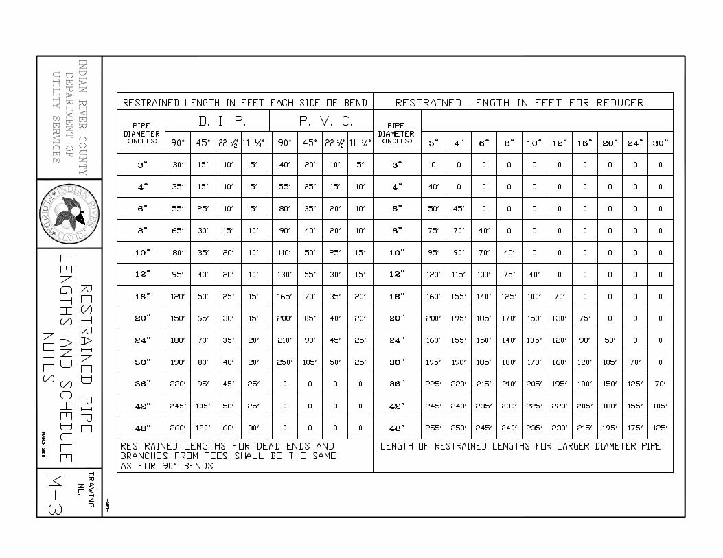
~ M > ~ "d z ~ > ~ ~ ~ RESTRAINED LENGTH IN FEET EACH SIDE OF BEND RESTRAINED LENGTH IN FEET FOR REDUCER e< ~ ~ ,;:: < Ul M M D. I. P. P. v. c. M ~ PIPE PIPE ~ z DIAMETER DIAMETER ~ :5 (") <INCHES) 90° 45° 22 'I; 11 1~0 90° 45° 22 'I; 11 1~0 <INCHES) 3" 4" 6" 6" 10" 12" 16" 20" 24" 30" (") 0 0 M ~ c:: [/] z 3" 30' 15' 10' 5' 40' 20' 10' 5' 3" 0 0 0 0 0 0 0 0 0 0 ~
e<
\1 4" 35' 15' 10' 5' 55' 25' 15' 10' 4" 40' 0 0 0 0 0 0 0 0 0
6" 55' 25' 10' 5' 80' 35' 20' 10' 6" 50' 45' 0 0 0 0 0 0 0 0
d ·• if) 8" 8" "- 65' 30' 15' 10' 90' 40' 20' 10' 75' 70' 40' 0 0 0 0 0 0 0
* J:NG'
I 10" 80' 35' 20' 10' 110' 50' 25' 15' 10" 95' 90' 70' 40' 0 0 0 0 0 0
1'1 12" 95' 40' 20' 10' 130' 55' 30' 15' 12" 120' 115' 100' 75' 40' 0 0 0 0 0 z Q /0 ---4 1'1 16" 120' 50' 25' 15' 165' 70' 35' 20' 16" 160' 155' 140' 125' 100' 70' 0 0 0 0
::r:: (/)
(/) ---4 20" 150' 65' 30' 15' 200' 85' 40' 20' 20" 200' 195' 185' 170' 150' 130' 75' 0 0 0
ZJ> /0 J> 24" 180' 70' 35' 20' 210' 90' 45' 25' 24" 160' 155' 150' 140' 135' 120' 90' 50' 0 0
Dz >----< ----jt::J z 30" 190' 80' 40' 20' 250' 105' 50' 25' 30" 195' 190' 185' 180' 170' 160' 120' 105' 70' 0 1'1 1'1 (/)(/) t::J 36" 220' 95' 45' 25' 0 0 0 0 36" 225' 220' 215' 210' 205' 195' 180' 150' 125' 70'
n u ::r:: >----< 42" 245' 105' 50' 25' 0 0 0 0 42" 245' 240' 235' 230' 225' 220' 205' 180' 155' 105'
1'1 u t::J 1'1 48" 260' 120' 60' 30' 0 0 0 0 48" 255' 250' 245' 240' 235' 230' 215' 195' 175' 125'
~ c ~
I RESTRAINED LENGTHS FOR DEAD ENDS AND LENGTH OF RESTRAINED LENGTHS FOR LARGER DIAMETER PIPE 1'1 BRANCHES FROM TEES SHALL BE THE SAME
AS FOR 90° BENDS
3: t=J
"' zJ>
I PS z
~ w Q

PRESSURE MAIN
ELEVATION -NIT-
NOTES
1. NEW OR RELOCATED, UNDERGROUND WATER MAINS CROSSING ANY EXISTING OR PROPOSED GRAVITY, VACUUM TYPE SANITARY SEWER, STORM SEWER, OR PRESSURE TYPE SANITARY SEWER, WASTEWATER, STORMWATER FORCE MAIN, OR PIPELINE CONVEYING RECLAIMED WATER SHALL BE LAID SO THE WATER MAIN IS AT LEAST 6", AND PREFERABLY 12", ABOVE OR A MINIMUM OF 12 INCHES BELOW THE OTHER PIPELINE. IT IS PREFERABLE TO LAY THE WATER MAIN ABOVE THE OTHER PIPELINE IF 36" MINIMUM COVER CAN BE MAINTAINED ABOVE THE WATER MAIN AND 6" OF SEPARATION BETWEEN THE WATER MAIN AND THE OTHER PIPELINE.
2. AT UTILITY CROSSINGS, ONE FULL LENGTH OF WATER MAIN PIPE SHALL BE CENTERED ABOVE OR BELOW THE OTHER PIPELINE SO THE WATER MAIN JOINTS WILL BE FAR AS POSSIBLE FROM THE OTHER PIPELINE. ALTERNATIVELY, AT SUCH CROSSINGS, THE PIPES SHALL BE ARRANGED SO THAT ALL WATER MAIN JOINTS ARE AT LEAST THREE FEET FROM ALL JOINTS IN VACUUM TYPE SANITARY SEWERS, STORM SEWERS, STORMWATER FORCE MAINS, OR PIPELINES CONVEYING RECLAIMED WATER, AND AT LEAST SIX FEET FROM ALL JOINTS IN GRAVITY OR PRESSURE TYPE SANITARY SEWERS, WASTEWATER FORCE MAINS, OR PIPELINES CONVEYING RECLAIMED WATER.
3. CONSTRUCT STANDARD CROSSING NOT TO EXCEED 75% OF THE MANUFACTURER'S MAXIMUM JOINT DEFLECTION.
4. OTHER METHODS OF RESTRAINT MAY BE USED AS APPROVED BY IRCDUS IN LIEU OF DEFLECTING THE PIPE AS SHOWN ABOVE.
5. TRACER WIRE SHALL BE INSTALLED ABOVE THE PIPE. (SEE DETAIL. M-13) 6. ALL WATER AND SEWER PIPING SHALL BE LOCATED A MINIMUM HORIZONTAL
SEPARATION EQUAL TO THE DEPTH OF THE PIPE PLUS THE DIAMETER OF THE PIPE FROM ANY PERMANENT ABOVE GROUND STRUCTURES (I.E. WALLS, TREES, TRANSFORMER PADS, ETC.) AND A MINIMUM HORIZONTAL SEPARATION EQUAL TO FOUR (4) FEET FROM ANY UNDERGROUND UTILITIES (I.E. GAS MAINS, TELEPHONE LINES, CABLE LINES, IRRIGATION MAINS, ETC.)
INDIAN RIVER COUNTY DEPARTMENT OF UTILITY SERVICES
UTILITY CROSSINGS
DRAWING NO.
M-4
PAVED AREA
UNPAVED AREA

WATER

MANHOLE FRAME 'WITH HINGED LID
PAVEMENT
CONCENTRIC CONCRETE MANHOLE TOP
SEAL SEE NOTE
GASKET
MANHOLE COATING SEE NOTE 2
AIR RELEASE VALVE DETAILS SEE M-8
SIDE OPENINGS TO BE SEALED SEE NOTE 7
3/4' GRAVEL DRAIN ROCK
NOTES
5'-0' ID------r
VARIES
ELEVATION 'WATER MAIN/'w'ASTE'w'ATER MAIN
FINISHED GRADE <S'w'ALD
8'
8'
___ __,
(/)
w t-i
n::: <[
>
~
co
" z
'"" ~
(\j .......
1. AIR RELEASE VALVE IS TO BE LOCATED INSIDE A CONCRETE MANHOLE IJITH HINGED LID. ALL MATERIALS PER IRCDUS APPROVED MANUFACTURER'S LIST
2. MANHOLES FOR SEIJER FORCE MAINS SHALL BE COATED. ALL COATING MATERIAL SHALL BE PER IRCDUS APPROVED MANUFACTURERS' PRODUCT LIST.
3. SEE AIR RELEASE DETAIL M-18. 4. SEE TRACER IJIRE DETAIL M-13. 5. IJASTEIJATER LIDS SHALL BE VENTED. 6. SEAL SHALL BE USED AT ALL JOINTS. SEE MANHOLE NOTES, S-5, NOTE 20. 7. OPENING AT BOTH SIDES OF THE MANHOLE TO BE SEALED IJITH MATERIALS PER IRCDUS
APPROVED MANUFACTURERS' PRODUCT LIST.
-ART-
INDIAN RIVER COUNTY DEPARTMENT OF UTILITY SERVICES
AIR RELEASE VALVE MANHOLE BELOW GROUND
DRAIJING NO.
M-7 CAUTDMATIC - WATER/WASTEWATER) MARCH 2018

DOWNWARD FACING SCREENED VENT FOR POTABLE APPLICATIONS
2" DIAMETER NIPPLE, STAINLESS STEEL, NPS THREADED OR FLANGED FITTING
ELEVATION
AIR RELEASE VALVE
2" DIAMETER STAIN LESS STEEL NPS THREADED NIPPLE OR FLANGED FITTING
2" BALL VALVE STAINLESS STEEL
2" STAINLESS STEEL WET TAPPING SLEEVE
WATER MAIN /WASTEWATER MAIN
NOTES
1. AUTOMATIC AIR RELEASE VALVE TO BE LOCATED ONLY WHERE CONDITIONS MAKE IT INACCESSIBLE OR AS REQUIRED BY THE IRCDUS.
2. AIR RELEASE RISERS TO BE IN A VERTICAL PLUMB POSITION AND PLACED AT SUMMITS IN THE SYSTEM. FOR DIRECTIONAL BORES, AIR RELEASE VALVES ARE TO BE PLACED ON EITHER SIDE OF THE CROSSING.
3. SEE TRACE WIRE DETAIL. M-13 4. FOR AIR RELEASE VALVES LARGER THAN 2" CONSULT IRCDUS.
-ART-
DRAWING NO. INDIAN RIVER CO UNTY
DEP ARTMENT OF UTILITY SERVICES
AIR RELEASE VALVE ASSEMBLY ABOVE GROUND M-8
(AUTOMATIC - WATER/WASTEWATER) MM~~8

4' SCHEDULE 80 - NPS THREADS
4' DR LARGER FORCE MAIN
FLANGED TEE ~ITH THREADS FOR CONNECTION TO AIR RELEASE VALVE
4' DR LARGER FORCE MAIN
FLANGE - CLASS 350
4' MINIMUM
FLANGED TEE ~ITH FLANGE FOR CONNECTION TO AIR RELEASE VALVE
NOTES
ISOMETRIC VIEVI ~ATER MAIN/~ASTE~ATER MAIN
1. IF FORCE MAIN IS 6' DR LARGER A 4' TAP AND AIR RELEASE VALVE SHALL BE USED.
2. SEE M-8 FOR AIR RELEASE VALVE DETAIL.
3. SEE TRACER ~IRE DETAIL. M-14.
INDIAN RIVER COUNTY
DEPARTMENT OF UTILITIES SERVICES
FLANGED TEE FOR ABOVE GROUND
AIR RELEASE VALVES ..... ..,
DRA\JING NO.
M-8 (A)

16" WA
TER M
AIN
48" CO
VER
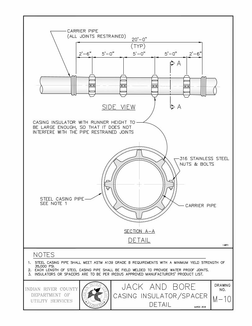
.-----CARRIER PIPE (ALL JOINTS RESTRAINED)
20'-o"
(TYP) 2'-6" 5'-0" 5'-0"
SIDE VIEW
CASING INSULATOR WITH RUNNER HEIGHT TO--BE LARGE ENOUGH, SO THAT IT DOES NOT INTERFERE WITH THE PIPE RESTRAINED JOINTS
STEEL CASING PIPE SEE NOTE 1
NOTES
SECTION A-A
DETAIL
5'-0" 2'-6"
316 STAINLESS STEEL NUTS & BOLTS
CARRIER PIPE
-ART-
1. STEEL CASING PIPE SHALL MEET ASTM A139 GRADE B REQUIREMENTS WITH A MINIMUM YIELD STRENGTH OF 35,000 PSI.
2. EACH LENGTH OF STEEL CASING PIPE SHALL BE FIELD WELDED TO PROVIDE WATER PROOF JOINTS. 3. INSULATORS OR SPACERS ARE TO BE PER IRCDUS APPROVED MANUFACTURERS' PRODUCT LIST.
JACK AND BORE DRAWING NO. INDIAN RIVER COUNTY
DEPARTMENT OF UTILITY SERVICE S
CASING INSULATOR/SPACER M-1 0 DETAIL MARa! 2018
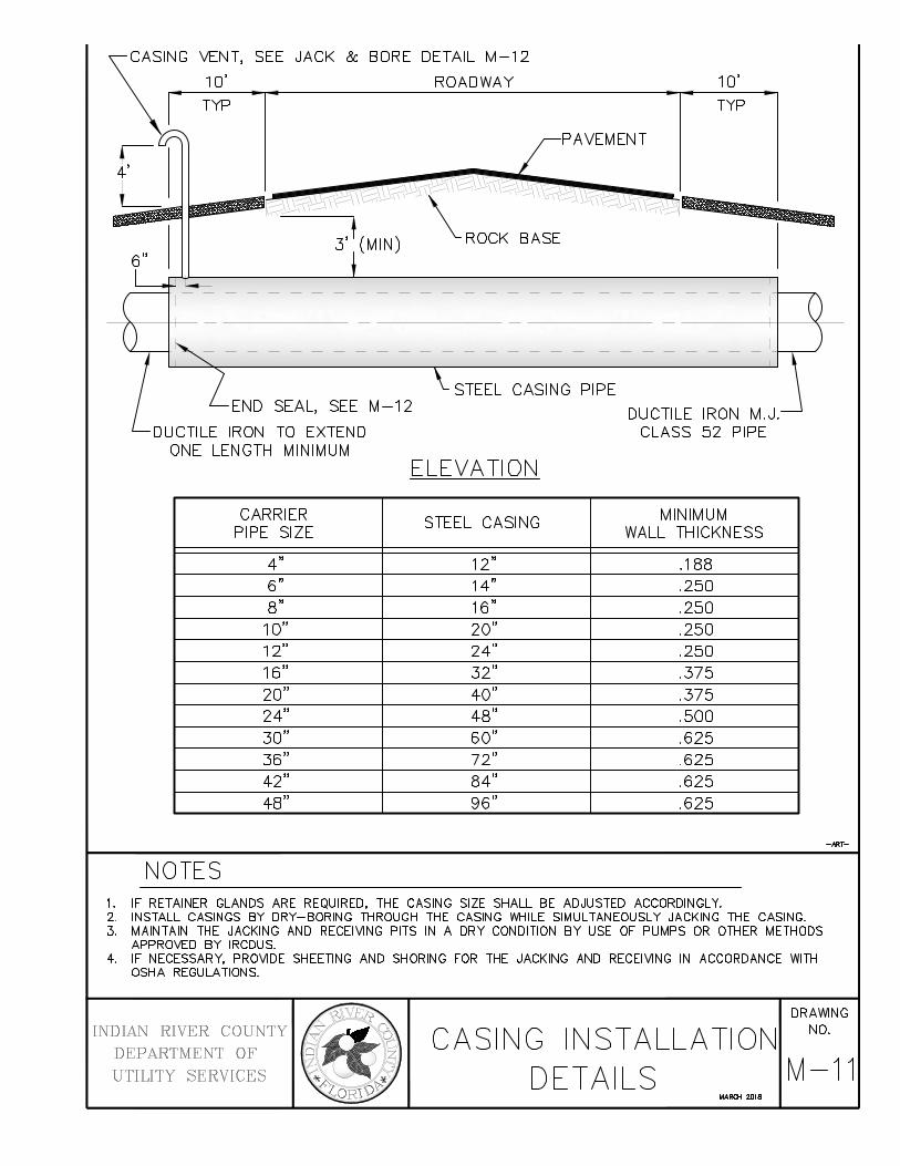
SEE JACK & BORE DETAIL M-12
ROADWAY
PAVEMENT
1 o' TYP
STEEL CASING PIPE END SEAL, SEE M-12
DUCTILE IRON TO EXTEND ONE LENGTH MINIMUM
ELEVATION
CARRIER STEEL CASING PIPE SIZE
4" 12" 6" 14" 8" 16" 1 o" 20" 12" 24" 16" 32" 20" 40" 24" 48" 30" 60" 36" 72" 42" 84" 48" 96"
NOTES
DUCTILE IRON M.J. CLASS 52 PIPE
MINIMUM WALL THICKNESS
.188
.250
.250
.250
.250
.375
.375
.500
.625
.625
.625
.625
1. IF RETAINER GLANDS ARE REQUIRED, THE CASING SIZE SHALL BE ADJUSTED ACCORDINGLY. 2. INSTALL CASINGS BY DRY-BORING THROUGH THE CASING WHILE SIMULTANEOUSLY JACKING THE CASING. 3. MAINTAIN THE JACKING AND RECEIVING PITS IN A DRY CONDITION BY USE OF PUMPS OR OTHER METHODS
APPROVED BY IRCDUS. 4. IF NECESSARY, PROVIDE SHEETING AND SHORING FOR THE JACKING AND RECEIVING IN ACCORDANCE WITH
OSHA REGULATIONS.
-ART-
DRAWING NO. INDIAN RIVER COUNTY
DEPARTMENT OF UTILITY SERVICE S
CASING INSTALLATION DETAILS M-11
MAROI 2018

180. RETURN BEND
316 STAINLESS STEEL HARDWARE CLOTH INSECT SCREEN
END SEAL TYP EACH END
USE NEOPRENE BOOT WTH 316 STAINLESS STEEL CLAMP TO SEAL ENDS OF CASING
MAIN
END SEAL
NOTES
0 I
-:.r
3" PIPE 316 STAINLESS STEEL
t----CASING VENT
ELEVATION
DRILL & THREAD OPENING, WELD CONNECTION, OR SADDLE AS REQUIRED
NEW STEEL CASING
-ART-
1. LOCATION OF CASING VENTS TO BE DETERMINED BY THE IRCDUS ENGINEER IN THE FIELD. CONTRACTOR TO PROVIDE FITTINGS AS REQUIRED.
2. NEOPRENE END SEAL TO BE PER IRCDUS APPROVED MANUFACTURERS' PRODUCT LIST.
INDIAN RIVER COUNTY DEPARTMENT OF UTILITY SERVICES
JACK AND BORE CASING VENT & END SEAL
DETAIL MARCH 2018
DRAWING NO.
M-12
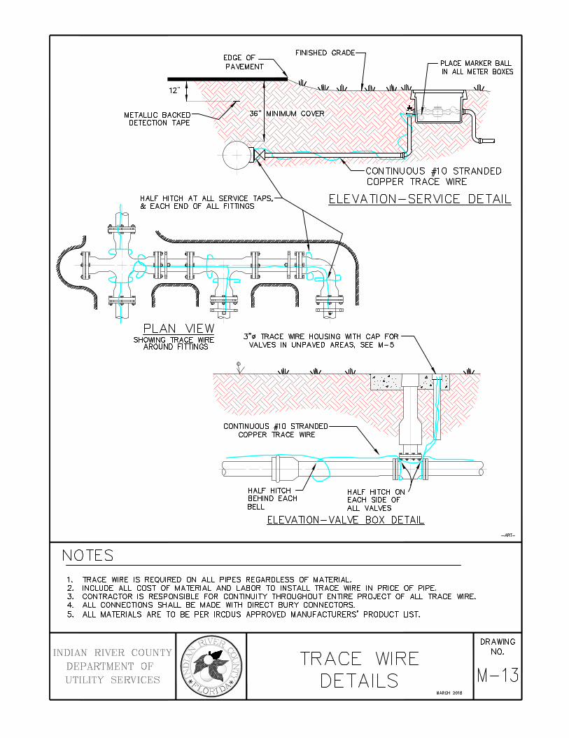
12"
PLACE MARKER BALL IN ALL METER BOXES
ELEVATION-SERVICE DETAIL
NOTES
PLAN VIEW SHOWING TRACE WIRE
AROUND FITIINGS 3"!1l TRACE WIRE HOUSING WITH CAP FOR
VALVES IN UNPAVED AREAS, SEE M-5
HALF HITCH BEHIND EACH BELL
HALF HITCH ON EACH SIDE OF ALL VALVES
ELEVATION-VALVE BOX DETAIL
1. TRACE WIRE IS REQUIRED ON ALL PIPES REGARDLESS OF MATERIAL. 2. INCLUDE ALL COST OF MATERIAL AND LABOR TO INSTALL TRACE WIRE IN PRICE OF PIPE. 3. CONTRACTOR IS RESPONSIBLE FOR CONTINUITY THROUGHOUT ENTIRE PROJECT OF ALL TRACE WIRE. 4. ALL CONNECTIONS SHALL BE MADE WITH DIRECT BURY CONNECTORS. 5. ALL MATERIALS ARE TO BE PER IRCDUS APPROVED MANUFACTURERS' PRODUCT LIST.
INDIAN RIVER C 0 UNTY DEPARTMENT OF UTILITY SERVICES
TRACE WIRE DETAILS
MARCH 2018
-ART-
DRAWING NO.
M-13

STATE PLANE COORDINATESSTATION NUMBER
OFFSET
AS-BUILT RECORD DRAWING 88TYPE OF VALVETOP ELEVATIONNUMBER OF TURNS TOOPEN OR CLOSE &DIRECTION
PARCEL NUMBER
This represents the basic style and format for
As-Built Record Drawings to be received by
the Indian River County Department of Utility
Services. Refer to drawings M-15 and M-16
for the minimum information requirements to
be provided by the engineer of record to
IRCDUS.
STATE PLANE COORDINATE AND STATION OFFSETREQUIRED FOR ALL VALVES, METERS, FITTINGS,MANHOLES, BLOW-OFFS, WATER SERVICES, FIREHYDRANTS, SERVICE SADDLES, CORP STOPS ANDPIPE AT 100' INTERVALS
INFO REQUIRED FORSERVICE SADDLEAND CORP STOP
ALL REQUIRED RECORD DRAWING INFORMATION SHALLHAVE OFF SET AND STATE PLANE STATION NUMBERS
STREET ADDRESS
INFO REQUIRED FORWATER METERS
NEW UTILITY LINE SHOWNWITH WIDER, SOLID LINE
STATIONING EVERY 100'
NEW UTILITY LINE SHOWNWITH WIDER, SOLID LINE
MA
TC
HLI
NE
A -
SH
EE
T 3
MATCHLINE INFOREQUIRED
DATUM USED

GENERAL NOTES
1. All As-Built Record Drawings shall meet the minimum requirements of the Chapter AJ-17, Florida
Administration Code Pursuant to Section 472 of the Florida Statutes
2. All As-Built Record Drawings shall be in State Plane Coordinates. State Plane Coordinates shall be based
on the Florida State Plane Horizontal data (East Zone); or Florida High Precision Geodetic Network
(superstation) and NAD 83/1999 - final adjustment, or the most current datum adopted by Indian River
County.
3. Florida State Plane Horizontal data and station off-set shall be tied to valves, meters, fittings, manholes,
blow-offs, water services, fire hydrants, service saddles, corp stops and pipe (pipe at 200' intervals).
4. All elevations shown shall be based on 1988 NAVD (North American Vertical Datum).
5. All As-Built Record Drawings shall be tied to a minimum of one (1) permanent reference monument
(P.R.M.) at the end of each project. One P.R.M. shall be tied to a minimum of one (1) section corner or
one-quarter (1/4) section corner whichever is closest to the project. State plane coordinates shall be
physically shown on the drawing next to the P.R.M. used.
6. Horizontal Control Monumentation for utility lines shall be a minimum of two (2) points at a maximum of
1,400 feet between points and shown on all plans.
7. Vertical Control (when required) for linear utility lines, such as water and sewer, shall have a maximum of
1,100 feet between existing construction or established benchmarks.
8. All incoming As-Built Record Drawings (24”x36”) shall state in 1" lettering "RECORD DRAWING" and the
datum used in 1" lettering in the lower right hand side of the drawing original and/or copies along with
as-built date. All incoming Record Drawings shall be received on a CD as an electronic copy, AutoCad
2015 format, or latest version, with a tie to a minimum of two (2) state plane coordinates. (NOTE: Prior to
submitting the electronic copy, one (1) copy of each as-built shall be submitted for review and approval.
After all approvals, (3) three (24”x36”) signed and sealed copies of each as-built shall be submitted. All
Record Drawings shall be in a minimum scale of 1"=40'.
9. A minimum text size of 1/8” is required on all construction/route survey and Record Drawings.
10. All As-Built Record Drawings shall be certified by the project engineer or contracting surveyor.

GENERAL NOTES
(continued)
11. All As-Built Record Drawings shall clearly depict utility lines that were constructed along with their
respective easement (if required). As-Built Record Drawings will not be accepted unless the verbiage
"PROPOSED" and/or "TO BE CONSTRUCTED" have been deleted on the drawing. As-Built Record
Drawings with "PROPOSED" or"TO BE CONSTRUCTED" terminology will not be accepted.
12. All new utility construction located within the rights-of-way, easements and alike shall be tied to the
respective rights-of-way, easement, etc. every 1,000 feet and change of direction.
13. All As-Built Record Drawings shall be complete and approved before commencement of field test.
14. Baseline of construction and station of items to be located on the center of the roadway, unless conditions
warrant and approved by IRCDUS. Baseline stationing shall be every 100', control points set at every
500' and at angle change of direction.
15. All new utility construction lines on all As-Built Record Drawings shall be shown with a wider, solid line.
Existing utility lines shall be shown with a thinner, dashed line.
16. Top of pipe elevations & stationing to be typed, listed, sealed & submitted by the engineer for locating
the air release valves as construction proceeds.
17. Show top elevation of the utility lines that were constructed and show existing utility lines for all utility
crossings.
18. Pump station power supply from FP&L or COVB electric power pole or transformer to the pump station
electric panel shall be included on the As-Built Record Drawing.
19. All fire hydrants and fire hydrant valves shall be located by state plane coordinates, station number and
offset and shall be clearly identified on the As-Built Record Drawing.
20. All newly constructed valves shall be clearly identified by size, type, top elevation and direction/number of
turns to open or close valve.

GENERAL INFORMATION REQUIREMENTS FOR ALL
CONSTRUCTION/ROUTE SURVEY AND AS-BUll T RECORD DRAWINGS
1. Existing right-of-way limits and/or easements within the limits of construction.
2. Survey baseline stationing every 1 00', control points set every 500', and at angle change of direction.
3. Show cross section elevations at grade every 1 00' for gravity sewer line construction and 500' for water line and force main construction. Elevations that reflect any significant change in grade between the previously stated footage shall be shown on plans.
4. Existing parcels, tracts, and lot corner locations shown with front footage dimensions per plat when platted. If construction project is along back of lots, then show back lot dimensions.
5. Existing roadway edge of pavement or edge of dirt road.
6. Existing utilities as located in field (water, sewer, telephone, electric, cable TV, etc.} (NOTE: Sunshine One to be contacted by surveying firm prior to survey locate; with the intent of county excavation.}
7. Existing utilities as associated with number 5 above (example: valves, meters, manholes, etc.)
8. Existing curbs, driveway widths and types.
9. Existing drainage pipe crossings and driveway culverts (type, sizes and invert elevations.}
10.Existing swales and/or ditches and elevations every 100' at top and bottom if within area of construction.
11. Existing fences.
12. Existing trees and/or shrubbery.
13. All other non-movable items such as mailboxes, flag poles, etc.
14.AII street names.
15.AII commercial and single/multi family residence must have parceii.D. indicated on the plan. _......_
~VII;j]
INDIAN RIVER COUNTY ~.··.· .. ··· .. ······ .• (8 I._, .· c, DEPARTMENT OF ~§ ~ ~ ~~
UTILITIES SERVICES ~A ;;::. ZoRl\:l~
GENERAL INFORMATION REQUIREMENTS
IEPTDIIER 1!1111
DRAW'ING NO.
M-16 CA)

INFORMATION REQUIREMENTS FOR ALL
AS-BUll T RECORD DRAWINGS
In addition to the requirements specified in Drawings M-16 and M-16(A), the following shall be included on all As-Built Record Drawings before acceptance by the Indian River County Department of Utility Services.
1. All as-built drawings (24"x36") shall state in 1" lettering "AS-BUlL T" located in the bottom right hand side of the drawing original and/or copies, along with the as-built date.
2. All utility as-built construction located within the rights-of-way, easements and alike shall be tied to the respective rights-of way, easements, etc., every 1,000 feet and change of direction.
3. All as-builts shall clearly depict as-built utility lines that were constructed along with their respective easement (if required). As-builts will not be accepted unless the verbiage "Proposed" and/or "To Be constructed" have been revised to read "AS-Built". As-built Construction drawings with, to be constructed terminology, will not be accepted.
4. All as-builts shall be certified by the project engineer or contracting surveyor.
5. All projects, which utilize lift stations, shall specify on plans as to whether or not subject lift stations are to remain private or are to be dedicated to the county.
6. All fire hydrants and valves shall be located with state plane coordinates, station number and off-set and shall be clearly identified on the as-built drawing.
7. All valves shall be clearly identfied by size, type, top elevation and direction/number of turns to open or close each valve.
8. Horizontal directional bores shall have a profile or cross section drawing and include the bore log.
9. The contractor is to provide the name of business or residence, street address and tax I. D. number for all properties adjacent to line extesions.
1 0. Shown with a thin dashed line, top elevations of As-Built utility lines and existing utility lines shall be shown for all utility crossings.
11. Baseline of construction and station of items to be on the centerline of the roadway.
12. As-Built utility lines shall be shown with a wider solid line.
13. Top of pipe elevations & stationing to be typed, listed, sealed & submitted for the engineer to locate the air release valves as construction proceeds.
14. All as-builts shall be complete and approved before commencement of field test.
~WE[r
INDIAN RIVER COUNTY ~~-· EQ I:? ...... e) DEPARTMENT OF 1~ > ;, g
UTILITIES SERVICES ~""'~""~ {QR~ ._..
AS-BUILT REQUIREMENTS
DRAWING NO.
M-16 CB)

ROUTE SURVEY REQUIREMENTS
1. All surveys that are required for engineering design use, and are located within a distance of one (1) mile
from any Indian River County Global Positioning System (G.P.S.) control project monuments, shall be tied
into the GPS monument from one (1) permanent reference point or the subdivision corner that is along the
survey route and shall then be tied to the survey base line.
2. Existing right-of-way limits and/or easements within the limits of construction.
3. Survey baseline stationing every 100', control points set every 500', and at angle change of direction.
4. Show cross section spot elevations at grade every 100' for gravity sewer line construction and 100' for
water line and force main construction. Elevations that reflect any significant change in grade between the
previously stated footage shall be shown on plans.
5. Existing parcels, tracts, and lot corner locations shown with front footage dimensions per plat when
platted. If construction project is along back of lots, then show back lot dimensions.
6. Existing roadway edge of pavement or edge of dirt road.
7. Existing utilities as located in field (water, sewer, telephone, electric, cable TV, street lights, etc.) (NOTE:
Sunshine One to be contacted by surveying firm prior to survey locate; with the intent of county
excavation.)
8. Existing utilities as associated with Note 6 above (example: valves, meters, manholes, etc.)
9. Existing curbs, sidewalks, driveway widths and types.
10. Existing drainage pipe crossings, catch basins, manholes, and driveway culverts (type, sizes and invert
elevations.)
11. Existing swales and/or ditches. Take cross section spot elevations every 100' at top and bottom if within
area of construction.
12. Existing fences.
13. Existing trees and/or shrubbery.
14. All other non-movable items such as mailboxes, flag poles, etc.
15. All street names. Street names shall appear on every printable sheet.
16. All commercial and single/multi family residence must have parcel I.D. and street address indicated on the
plan.
17. All fire hydrants and fire hydrant valves shall be clearly identified.
18. All utility valves shall be clearly identified.
19. Route surveys performed for water assessment projects may require residential well locations.

VARIES 2'-6'CMIN> <PER MANUFACTURERS' SPECIFICATION) 2'-6'CMIN>
VARIES VARIES
"""' :z
~ . C)
I ru
CONCRETE PAD-3,000 PSI ~ I COMMERCIAL GRADE ~
FIBER MESH CONCRETE C6' THICK MINIMUM, LENGTH AS REQUIRED)
PLAN VIE\J SADDLE SUPPORT SS
PLUG VALVE 'w'/LIMITING SET-UP AND ELECTRIC ACTUATOR
'WIRE TO LEVEL
SAMPLE TAP METER 'w'ITH TOTALIZER <NOTE 3)\114'91
CHECK VALVE 'w'/'w'EIGHTED LEVER ARM
90• BEND <TYP) CFLG x FLG)
PRESSURE TRANSDUCER <BURIED IN CDNDUID
CONCRETE PAD C6' THICK MINIMUM)
FLOAT S'w'ITCH CABLE TO CONTROL PANEL <BURIED IN CONDUIT)
1/2' PREFORMED JOINT MATERIAL TO BE PLACED BET'w'EEN PIPE AND CONCRETE DR PIPE SLEEVE
FLANGED AND MJ SPOOL ELEVATION CONNECTION <TYP)
CONTINUE DISCHARGE PIPING <SEE R-2)
-IIRT-
NOTES 1. ALL ABOVE GROUND PIPING 8. FITTINGS TO BE FLANGED AND DUCTILE IRON. 2. ALL ABOVE GROUND PIPING, FITTINGS AND VALVE BOX LIDS SHALL BE PAINTED PANTDNE PURPLE C522D. 3. PROVIDE A HANGING PLACARD 'w'ITH THE 'w'DRDS 'RECLAIMED 'WATER IN USE.' 4. PROPELLER DR MAG METER SHALL BE LINKED TO IRCDUS REMOTE TRANSMITTING UNIT CRTU) FOR REMOTE
MONITORING BY IRCDUS. THE METER SHALL REPORT IN GALLONS PER MINUTE. PLUG VALVE SHALL BE REMDTEL Y ACTUATED VIA IRCDUS AND BY PRESSURE TRANSDUCER IN LAKE. PLUG VALVE SHALL REPORT 'PERCENTAGE OPEN' POSITION. INTEGRATE ALL LOGIC 'w'ITH IRCDUS SCADA SYSTEM.
4. ALL MATERIALS ARE TO BE PER IRCDUS APPROVED MANUFACTURERS' PRODUCT LIST. 5. A TELEMETRY AND MONITORING DEVICE IS REQUIRED AT DISCHARGE. DEVICE TO BE
INSTALLED IN STRICT ACCORDANCE 'w'ITH MANUFACTURERS INSTRUCTIONS.
6. ELECTRICAL PANEL SHALL BE PER LIFT STATION ELECTRICAL PANEL, SEE DETAIL S-17, S-18 AND S-19. ELECTRICAL PANEL TO BE LOCATED AS CLOSE TO METER AS PRACTICAL.
INDIAN RIVER COUNTY DEPARTMENT OF UTILITY SERVICES
RECLAIMED wATER METER/VALVE
ASSEMBLY DETAIL HA~CH ana
DRA'w'ING NO.
R-1
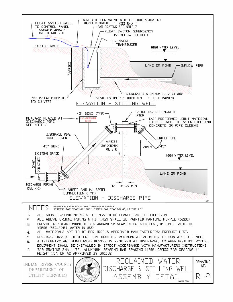
FLOAT SWITCH CABLE TO CONTROL PANEL
<BURIED IN CONDUIT) CSEE DETAIL R-D --[(!)
VIIRE <TD PLUG VALVE VIITH ELECTRIC ACTUATOR> <BURIED IN CONDUITl CSEE R-D
BAR GRATING SEE NOTE 7
FLOAT SWITCH <EMERGENCY OVERFLOW CUTOFF)
HIGH VIATER LEVEL ...
LAKE DR POND
CRUSHED STONE 12' THICK MIN <LENGTH VARIES) 2'x2' PREFAB CONCRETE BOX CULVERT ELEVATION - STILLING \JELL
PLACARD PLACED AT--~ DISCHARGE PIPE SEE NOTE 3
CSEE R-D
DISCHARGE PIPE DUCTILE IRON
NOTES GRAINGER CATALOG - BAR GRATING ALUMINUM BEARING BAR SPACING 1.188·, CROSS BAR SPACING 4•, HEIGHT LY
LAKE DR POND
1. ALL ABOVE GROUND PIPING 8. FITTINGS TO BE FLANGED AND DUCTILE IRON. 2. ALL ABOVE GROUND PIPING 8. FITTINGS SHALL BE PAINTED PANTONE PURPLE (522C), 3. PROVIDE A PLACARD MOUNTED ON STANDARD 'U' SHAPE METAL SIGN POST, 8' LONG, WITH THE
VIORDS 'RECLAIMED VIATER IN USE.' 4. ALL MATERIALS ARE TO BE PER IRCDUS APPROVED MANUFACTURERS' PRODUCT LIST.
-ART-
5. DISCHARGE INVERT TO BE ONE PIPE DIAMETER <MINIMUM) ABOVE METER TO MAINTAIN FULL PIPE. 6. A TELEMETRY AND MONITORING DEVISE IS REQUIRED AT DISCHARGE, AS APPROVED BY IRCDUS.
EQUIPMENT SHALL BE INSTALLED IN STRICT ACCORDANCE WITH MANUFACTURERS INSTRUCTIONS. 7. BAR GRATING SHALL BE ALUMINUM, BEARING BAR SPACING 1.188', CROSS BAR SPACING 4'
HEIGHT 1.5', DR AS APPROVED BY IRCDUS.
INDIAN RIVER COUNTY DEPARTMENT OF UTILITY SERVICES
RECLAIMED wATER DISCHARGE ~ STILLING \JELL
ASSEMBLY DETAIL MII~CH 2018
DRAWING NO.
R-2

COMMON
,-... z b :::;E I -......
~ 0
I -n
DOUBLE SERVICE TYPICAL
STANDARD ''y'' BRANCHES TO BE LOCATED IN THE FIELD
SINGLE SERVICE TYPICAL
6"x6" WYE COMMERCIAL_/ 6"x4" WYE RESIDENTIAL
PLAN VIEW IRCDUS RESPONSIBILITY EASEMENT OR R.O.W.
,--------------------------MARKER 'tROAD ELEVATION (SEE NOTE 5
CROWN OF ROAD
MARKER BALL TAPEDJ TO 6"x4" WYE {TYP) DEPTH TO BE DETERMINED
IN THE FIELD AS REQUIRED AVOID OTHER UTILITIES {TYP)
RISER & CLEANOUTS NOT SHOWN FOR CLARITY
ELEVATION -ART-
NOTES 1. SANITARY SEWER LATERALS SHALL BE A MINIMUM OF 6" IN DIAMETER. 2. MAGNETIC DETECTION TAPE SHALL BE INSTALLED OVER TOP OF ALL SEWER MAINS AND SERVICE LATERALS. 3. ALL MATERIALS ARE TO BE PER IRCDUS APPROVED MANUFACTURERS' PRODUCT LIST.
4. 4" ELECTRONIC MARKER BALLS TO BE TAPED TO 6"x4" WYE 24" BELOW FINISHED GRADE. 5. FOR RISER AND CLEANOUT DETAIL SEE DRAWING S-3.
AND FOR CUTTING SEWER CLEANOUT TO FINISH GRADE PRIOR TO CONNECTION. SEE DETAIL S-3. 6. RISERS AND CLEANOUT SHALL NOT BE CONSTRUCTED WITHIN 12" OF SIDEWALK.
INDIAN RIVER COUNTY DEPARTMENT OF UTILITY SERVICES
STANDARD LATERAL (SHALLOW SEWER)
MARCH 201B
DRAWING NO.
S-1

-~~~-------------------------~I~RC~D~US~R~E~SP~O~N~SIB~IL~IT~Y ---------------------------~----~- EASEMENT OR R.O.W. .,.I.,.
SIDEWALK (SEE NOTE 5 &: DETAIL S-3) NO SIDEWALK
4" RISER PIPE (TYP) SEE NOTE 4 AND S-3 Wl>z <( _J ;!::: DEPTH 2' MINIMUM DEPTH 2' MINIMUM
>- I f- LL.. 0:: 0 w I a.. f-
~IG 0...1(2
MARKER BALL TAPED TO
6"x4" WYE (TYP)
CONTINUE GRAVEL BED UNDER & PARALLEL TO PIPE INTO UNDISTURBED SOIL TO PROPERTY LINE
NOTES
DEPTH TO BE DETERMINED IN THE FIELD AS REQUIRED TO AVOID UTILITIES .3'-0" DEEP (MINIMUM)
STANDARD LATERAL DETAIL (S-1)
Cf_ROAD ELEVATION
ETCH CURB WITH "s" FOR SEWER LATERALS
0 I
r-..
TYPICAL TRENCH CONTOUR
DURING CONSTRUCTION
BENDS AS REQ'D
SAND EXCAVATION
ELEVATION
MARKER BALL
STANDARD 6"x4" WYE {TYP) (SEE S-3)
STANDARD "y" BRANCH TO BE LOCATED IN FIELD
1. 3/4" GRAVEL BEDDING SHALL BE USED FOR EXCAVATION IN ROCK. SAND BEDDING SHALL BE USED FOR EXCAVATION IN SAND.
2. ALL MATERIALS ARE TO BE PER IRCDUS APPROVED MANUFACTURERS' PRODUCT LIST.
3. MARKER BALLS TO BE TAPED TO 6"x4" 24" BELOW FINISHED GRADE.
-ART-
4. PLUMBING CONTRACTOR SHALL BE RESPONSIBLE FOR RISER PIPE WITH BEND FOR SERVICE CONNECTION AND FOR SETTING 4" SEWER CLEANOUT TO FINISH GRADE PRIOR TO CONNECTION.
5. RISERS AND CLEANOUTS SHALL NOT BE CONSTRUCTED WITHIN 12" OF SIDEWALK.
INDIAN RIVER COUNTY DEPARTMENT OF UTILITY SERVICES
MODIFIED RISER LATERAL (DEEP SEWER)
MARCH :ro18
DRAWING NO.
S--2

PLUMBING CONTRACTOR RESPONSIBLE FOR
RISER & CLEAN OUT
INSTALLED PLUG (TYP) \ (4" CLEAN OUT) \
INSTALLED PLUG (6" CLEAN OUT)
24"-36"
STANDARD 6"x4" WYE (TYP) 45" BENDS FOR RISER PIPE (TYP) IRCDUS CONTRACTOR RESPONSIBLE FOR SEWER LATERALS
DETAIL
NOTES 1. ALL SEWER LATERALS (SINGLE, DOUBLE, DEEP OR SHALLOW) SHALL HAVE A RISER PIPE
WITH BENDS AS REQUIRED FOR SERVICE CONNECTIONS AND WITH A 4" SEWER CLEANOUT AT FINISHED GRADE.
2. PLUMBING CONTRACTOR WILL BE RESPONSIBLE FOR RISER PIPE WITH BEND FOR SERVICE CONNECTION AND FOR CUTIING 4" SEWER CLEANOUT TO FINISH GRADE PRIOR TO CONNECTION.
3. MARKER BALLS TO BE TAPED TO 6"x4" 24" BELOW FINISHED GRADE.
4. ALL MATERIALS ARE TO BE PER IRCDUS APPROVED MANUFACTURERS' PRODUCT LIST.
INDIAN RIVER COUNTY DEPARTMENT OF
UTILITIES SERVICES
SEWER LATERAL RISER ~~~"; (DEEP OR SHALLOW SE~~~ (A)

w>z<C ::J:S:
PLUMBING CONTRACTOR RESPONSIBLE FOR RISER & CLEAN OUT
COMMON PROPERTY LINE _ ____,
I >- I LL f- l o a:: I wfa...I 0~ 0:::a._a::
INSTALLED PLUG IN INVERTED POSITION SO 2" SQUARE NUT FACES INTO PIPE FINISHED GRADE
( 4" CLEAN OUT)
INSTALLED PLUG (6" CLEAN OUT)
CUSTOMER RESPONSIBILITY ---
" ~ l ~ "~L (' ~ ~+----------
STANDARD 6.~4• WYE (TYP) \ IRCDUS RESPONSIBILITY J + 4" ELECTRONIC MARKER BALL 45" BENDS FOR RISER PIPE (TYPICAL)
PLUMBING CONTRACTOR RESPONSIBLE FOR SEWER LATERALS
TAPED TO 6"x4" WYE (TYP)
ELEVATION
NOTES 1. ALL SEWER LATERALS (SINGLE, DOUBLE, DEEP OR SHALLOW) SHALL HAVE A RISER PIPE
WITH BENDS AS REQUIRED FOR SERVICE CONNECTIONS AND WITH A 4" SEWER CLEANOUT AT FINISHED GRADE.
2. CONTRACTOR SHALL BE RESPONSIBLE FOR RISER PIPE WITH BEND FOR SERVICE CONNECTION AND FOR SETTING 4" SEWER CLEANOUT TO FINISH GRADE PRIOR TO CONNECTION.
3. MARKER BALLS TO BE TAPED TO 6"x4" WYE 24" BELOW FINISHED GRADE.
4. ALL MATERIALS ARE TO BE PER IRCDUS APPROVED MANUFACTURERS' PRODUCT LIST.
5. CLEANOUT SHALL NOT BE CONSTRUCTED WITHIN 12" OF SIDEWALK.
DRAWING INDIAN RIVER COUNTY
DEPARTMENT OF UTILITY SERVICES
SEWER LATERAL RISER SNo.3 DETAILS -

SANITARY
SEWER

MANHOLE NOTES
1. Reinforcing area of 0.20 sq. in./ft. for wall section, minimum to meet or exceed A.S.T.M. A-185.
2. All cement mortar to be Type I or Type II.
3. All cement for precast manholes to be minimum 3,000 p.s.i. to meet or exceed A.S.T.M. C-478.
4. Bottoms and channels of all manholes to be a minimum of 2,5000 p.s.i. Fill concrete shall be finished
smooth with steel trowel.
5. Concrete manholes to have a minimum wall thickness of 8".
6. Inside and outside of manhole shall be coated with two coats of EW-1 water based epoxy. (1) coat red,
one coat black, for a total of two coats.
7. Channels to be formed in all manholes to accept t.v.camera.
8. Orient eccentric cone as required by engineer in field.
9. Bottom section to be monolithic pour except where drop connection required.
10. Connections to existing manhole and lift station wet well structures shall be by means of boring a
penetration in the structure, rather than punching. the contractor shall take positive measures to prevent
any concrete or construction debris from entering the wastewater system.
11. Buoyancy calculations shall be required for all manholes.
12. No. 4Ø bars, 9" O.C. required each way in slab (top and bottom).
13. 2 courses brick minimum, 6 courses maximum required between all precast manhole tops and casings.
14. 3 /4" crushed stone foundation for a minimum depth of 12" shall be provided as required by IRCDUS.
15. Manhole lid shall be traffic bearing (H-20 loading).
16. Sewer pipe inverts at bottom of manholes shall have as invert elevation differential of 0.1 feet for a change
in direction and 0.05 feet for a straight run.
17. A watertight rain guard boot, to be per IRCDUS Approved Manufacturer's Product List, shall be provided
for all manhole frame/covers.
18. Materials for lining manholes, where required, to be per IRCDUS, Approved Manufacturer's Product List.
Manhole liners shall be installed on all manholes receiving pumped sewage, plus 5 manholes in each
direction. (As directed by IRCDUS.)
19. Pump out manhole shall be located within 20' of lift station and constructed out of right-of-way.
20. All existing manholes, lift station wet wells, valve vaults, joints and courses of brick shall be sealed.
21. Slopes on all channel bottoms to be equal to slopes of pipe entering and exiting manhole.
22. Diameters of manholes shall be:

MANHOLE AND COVER
JOINT TO BE--+"-7LLJ FILLED WITH RAM-NECK OR APPROVED EQUAL
FILL CONCRE OR BRICK W/TYPE I OR TYPE II CEMENT MORTAR 5'-0" ID
FINISHED GRADE
s: SEE MANHOLE EFFLUENT & INFLUENT DETAIL
INVERT
~------_......._--+--6"
7'-4" OD
ELEVATION SECTION A-A
Q A
MANHOLE FRAME AND COVER NOT SHOWN FOR CLARITY
PLAN VIEW
TO BE USED WHEN CUT CLASSIFICATION IS 6' -0" OR L
NOTES 1. SEE MANHOLE NOTES DRAWING NO. S-5
2. SEE STANDARD MANHOLE CASTING DRAWING NO. S-4
3. SEE PIPE OPENING DETAIL DRAWING NO. S-11
4. SEE MANHOLE EFFLUENT & INFLUENT DETAIL DRAWING NO. S-12
5. SEAL SHALL BE USED AT ALL JOINTS. SEE DRAWING S-5, NOTE 20.
INDIAN RIVER COUNTY
DEP ARTMENT OF
UTILITY SERVICES
MANHOLE STANDARD-SHALLOW
MARCH 20111
-ART-
DRAWING NO.
S-6

MANHOLE FRAME & COVER
4 A
MANHOLE FRAME AND COVER
JOINT TO BE--
SEE MANHOLE EFFLUENT & INFLUENT DETAIL
ADDITIONAL REINFORCING BARS REQUIRED AROUND OPENING IN TOP SLAB. SLAB TO BE TO BE TRAFFIC BEARING. SUBMIT SHOP DRAWING FOR APPROVAL.
PLAN VIEW
FILLED WITH RAM-NECK OR APPROVED EQUAL
t BRICK LEVEUNG RINGS t 2 COURSES (MIN)
.-+-,-....,......,..£~-------1':~....,....,....7""?1 -----'- 6 COURSES (MAX)
SEE PIPE OPENING DETAIL (S-11)
FILL CONCRETE OR BRICK W/TYPE I OR TYPE II CEMENT MORTAR
5'-0" ID
ELEVATION SECTION A-A
8"
FLOW
(f) (f) w _J
0::: 0 0 I
co (f) w 0::: <( >
8"
PIPE INVERT
TO BE USED WHEN CUT CLASSIFICATION IS 6' -0" OR LESS -ART-
NOTES 1. SEE MANHOLE NOTES ON DRAWING NO. S-5 2. SEE STANDARD MANHOLE CASTING DRAWING NO. S-4
3. SEE PIPE OPENING DETAIL DRAWING NO. S-11 4. SEE MANHOLE EFFLUENT & INFLUENT DETAIL DRAWING NO. S-12 5. USE 5' -0" I. D. MANHOLE AS DIRECTED BY THE IRCDUS. 6. SEAL SHALL BE USED AT ALL JOINTS. SEE DRAWING S-5, NOTE 20.
IND IAN RIVER COUNTY DEPARTMENT OF
UTILITY SERVICE S
DRAWING NO. MANHOLE
SLAB-TOP DETAILS s-7 MARa! 2018

CUT CLASSIFICATION HEIGHT
SEAL
b I
to
SEAL:
FILL CONCRETE OR BRICK W/TYPE I
OR TYPE II
5'-0" ID
MANHOLE FRAME & COVER
SEE MANHOLE EFFLUENT &
JOINT TO BE FILLED WITH RAM-NECK OR
APPROVED EQUAL
SEE PIPE OPENING DETAIL (S-11)
CEMENT MORTAR ELEVATION SECTION A-A
MANHOLE FRAME & COVER NOT SHOWN FOR CLARITY
PLAN VIEW
TO BE USED WHEN CUT CLASSIFICATION IS OVER 6'-0"
NOTES 1. SEE MANHOLE NOTES ON DRAWING NO. S-5
2. SEE STANDARD MANHOLE CASTING DRAWING NO. S-4
3. SEE PIPE OPENING DETAIL DRAWING NO. S-11
4. SEE MANHOLE EFFLUENT & INFLUENT DETAIL DRAWING NO. S-12
5. SEAL SHALL BE USED AT ALL JOINTS. SEE DRAWING S-5, NOTE 20.
IND IAN RIVER CO UNTY DEPARTMENT OF
UTILITY SERVICES
MANHOLE STANDARD-DEEP
MARa! 2018
-ART-
DRAWING NO.
S-8

PIPE TO MANHOLE CONNECTIONS NEOPRENE BOOT WITH STAINLESS STEEL ACCESSORIES, FOR TOP AND BOTTOM ENTRIES SEE PIPE OPENING IN MANHOLE DETAIL S-11
8"
6" (MIN) (TYP)
5'-0" ID STANDARD "T" BRANCH
FLOW
CONCRETE COVER 6" MIN. ALL AROUND CONCRETE TO BE A MIN. OF 3,000 PSI (BY CONTRACTOR)
STANDARD LONG
EFFLUENT & INFLUENT RADIUS ELBO/ SEE MANHOLE
3: DETAIL S-12 0 _J
LL CONSTRUCT CHANNEL
FILL CONCRETE OR BRICK W/TYPE I OR TYPE II CEMENT MORTAR CONSTRUCT CHANNEL
SLOPE 2"/FT
ELEVATION SECTION A-A
PLAN VIEW
TO BE USED WHERE DROP IS 2' OR MORE
NOTES 1. SEE MANHOLE NOTES DRAWING NO. S-5
2. SEE PIPE OPENING DETAIL DRAWING NO. S-11
3. SEE MANHOLE EFFLUENT & INFLUENT DETAIL DRAWING NO. S-12
4. SOLVENT JOINTS SHALL NOT BE USED FOR DROP PIPE
5. SEWER LATERALS SHALL NOT BE CONNECTED DIRECTLY INTO MANHOLES
INDIAN RIVER COUNTY DEPARTME NT OF UTILITY SE RVICES
MANHOLE OUTSIDE- DROP
MARai 2018
- ~ A
-ART-
DRAWING NO.
S-9

PIPE INVERT
DROP LESS THAN 24"
SEE PIPE OPENING DETAIL (S-11)
FILL CONCRETE OR BRICK W/TYPE I OR TYPE II CEMENT MORTAR
ELEVATION SECTION A-A
PIPE TO MANHOLE CONNECTIONS NEOPRENE BOOT WITH STAINLESS STEEL 316 ACCESSORIES, FOR TOP AND BOTTOM ENTRIES SEE PIPE OPENING IN MANHOLE DETAIL S-11
CONSTRUCT CHANNEL SLOPE 2"/FT
~-SEE MANHOLE EFFLUENT & INFLUENT DETAIL S-12
CONSTRUCT CHANNEL
PLAN VIEW
TO BE USED WHERE DROP IS LESS THAN 2'
NOTES 1. SEE MANHOLE NOTES ON DRAWING NO. S-5
2. SEE PIPE OPENING DETAIL DRAWING NO. S-11
3. SEE MANHOLE EFFLUENT & INFLUENT DETAIL DRAWING NO. S-12
IND IAN RIVER CO UNTY DEPARTMENT OF
UTILITIES SERVIC ES
MANHOLE INSIDE-DROP
MARa! 2018
-ART-
DRAWING NO.
S-10
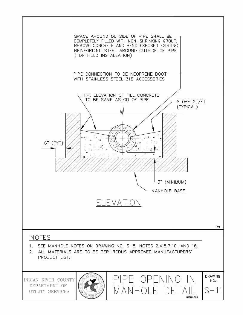
SPACE AROUND OUTSIDE OF PIPE SHALL BE COMPLETELY FILLED WITH NON-SHRINKING GROUT. REMOVE CONCRETE AND BEND EXPOSED EXISTING REINFORCING STEEL AROUND OUTSIDE OF PIPE (FOR FIELD INSTALLATION)
PIPE CONNECTION TO BE NEOPRENE BOOT ----1 WITH STAINLESS STEEL 316 ACCESSORIES
H.P. ELEVATION OF FILL CONCRETE TO BE SAME AS OD OF PIPE SLOPE 2"/FT
(TYPICAL)
6" (TYP) A . : ·. q .. ·.a
I ~r/
..
ELEVATION
NOTES
•
. ' . . .tl_ ·.
3" (MINIMUM)
MANHOLE BASE
1. SEE MANHOLE NOTES ON DRAWING NO. S-5, NOTES 2,4,5,7.10, AND 16. 2. ALL MATERIALS ARE TO BE PER IRCDUS APPROVED MANUFACTURERS'
PRODUCT LIST.
INDIAN RIVER COUNTY DEPARTMENT OF UTILITY SERVICES
PIPE OPENING IN MANHOLE DETAIL
MARCH 2018
-ART-
DRAWING NO.
S-11

PIPE TO MANHOLE CONNECTION TO BE NEOPRENE BOOT WITH STAINLESS STEEL 316 ACCESSORIES. SEE PIPE OPENING IN MANHOLE DETAIL S-11
EFFLUENT PIPE
...
....
FILL CONCRETE OR BRICK W/TYPE I OR TYPE II CEMENT MORTAR
ELEVATION
BENCH WALL TO SLOPE 2"/FT TOWARD CHANNEL
3/4" ROCK .-(20' UPSTREAM)
CHANNEL TO HAVE SMOOTH TROWEL FINISH
PIPE JOINT DETAIL AT MANHOLE
NOTES
1. PIPE JOINT DETAIL IS TYPICAL FOR ALL PIPE TO MANHOLE CONNECTIONS.
2. ALL MATERIALS ARE TO BE PER IRCDUS APPROVED MANUFACTURERS' PRODUCT LIST.
3. 3/4" ROCK TO BE USED AS BEDDING FOR 20' UPSTREAM AND DOWNSTREAM
OF MANHOLE. 4. SEE MANHOLE NOTES ON DRAWING S-5, NOTE 16.
-ART-
INDIAN RIVER COUNTY DEPARTMENT OF UTILITY SER VICES
MANHOLE DRAWING
INFLUENT & EFFLUENT s-12 p I p I N G D ETA I L MARCH"""

MANHOLE FRAME AND COVER
FINISHED GRADE
FORCE MAIN
RESTRAINED JOINTS WITH MEGA LUGS OR OTHER APPROVED EQU AL (TYP)
SEAL
ASPH ALT PAVEMENT
FIBERGLASS LINER
5'-0" ID
DOWN STREAM INLET GRAVITY SEWER
RESTRAINED JOINTS WITH--e~3 MEGA LUGS OR OTHER APPROVED EQUAL (TYP)
STANDARD LONG RADIUS ELBOW
INVERT TO BE THE SAME AS DOWNSTREAM INLET
CUT HOLE ( USE NEOPRENE BOOT TO SEAL AS PER DR AWING S-11) 6"(MIN TYP)
GRAVITY
ELE VATION
NOTES 1. SEE MANHOLE NOTES ON DRAWING NO. S-5
2. SEE PIPE OPENING IN MANHOLE DETAIL DRAWING NO. S-11
3. SEE MANHOLE INFLUENT & EFFLUENT PIPING DETAIL DR AWING NO. S-12 4. NO INSIDE DROP WILL BE ACCEPTED FOR FORCE MAIN TIE-INS. 5. MATERI ALS FOR LINING MANHOLES SHALL BE EQU AL TO THAT MANUFACTURED BY ASSOCIATED
FIBERGLASS ENGINEERS OR APPROVED EQUAL AND SH ALL BE ENGINEERED TO A STANDARD OF 16,000-POUND VERTICAL DYNAMIC WHEEL LOAD (AASHTO H-20). FIBERGLASS LINERS SHALL BE INSTALLED ON ALL MANHOLES RECEIVING PUMPED SEWAGE.
6. ALL MATERIALS ARE TO BE PER IRCDUS APPROVED MANUFACTURERS' PRODUCT LIST. 7. SEAL SH ALL BE USED AT ALL JOINTS.
INDIAN RI VER COUNTY DEPARTMENT OF UTILITY SERVICES
FORCE TO
MAIN TIE-IN MANHOLE
NARCH 201!
- ART-
DRAWING NO.
S-13
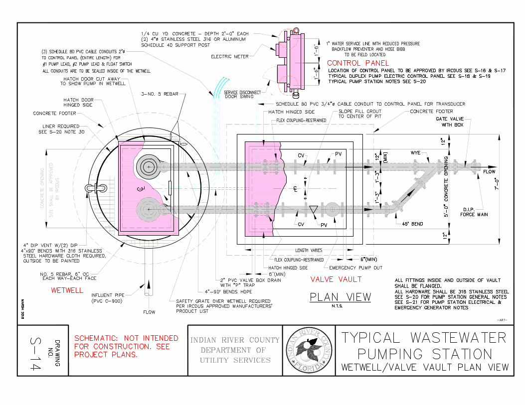
1/ 4 CU. YD. CONCRETE - DEPTH 2' - 0" EACH (2) 4"~ STAINLESS STEEL 31 6 OR ALUMINUM SCHEDULE 40 SUPPORT POST
(3) SCHEDULE 8D PVC CABLE CONDUITS 2''0 --~ TO CONTROL PANEL (ENTIRE LENGTH) FOR #1 PUMP LEAD, #2 PUMP LEAD & FLOAT S\\I TCH
ALL CONDUITS ARE TO BE SEALED INSIDE OF THE WETWELL
HATCH DOOR CUT AWAY
0
"' ~
"' 0
2 o-: w o._ (fl Q_ ~ 6 0
w w u f- m e>; w _j >-n-: u <;!rn z I 0 L'l u
w N ill
TO SHOW PUMP IN WETWELL
HATCH DOOR HINGED SIDE
/
I I
I I I I I \ \ \
'-.. 4" DIP VENT W/ (2) DIP '-.
4"x90' BENDS WITH 316 STAINLESS'- '-... STEEL HARDWARE CLOTH REQUIRED, OUTSIDE TO BE PAINTED
NO. 5 REBAR, 6" DC EACH WAY-EACH FACE
WETWELL
3- NO. 5 REBAR
ELECTRIC METER
HATCH HI NGED SIDE 6"( MIN )
2" PVC VALVE BO X DRAIN WI TH "p " TRAP
4" - 90 ' BENDS HOPE INFLUENT PIPE (PVC C- 900)
FLOW
SAFETY GRATE OVER WETWELL REQUIRED PER IR CDU S APPROVED MAN UFACTURERS' PROD UCT LI ST
()) D
I :;o
Z)>
9§ ~ z ~
(;)
SCHEMATIC: NOT INTENDED FOR CON STRU CTI ON. SEE PROJECT PLANS.
INDIAN RIVER COUNTY DEPARTMENT OF UTILITY SERVICES
1" WATER SERVICE LINE VH H REDUCED PRESSURE BACKFLOW PREVENTER AND HOSE BIBB
TO BE FIELD LOCATED
CONTROL PANEL LOCATION OF CONTROL PANEL TO BE APPROVED BY IRCDUS SEE S-16 & S-17 TYPICAL DUPLEX PUMP ELECTRIC CONTROL PANEL SEE S-18 & S-19 TYPICAL PUMP STAllON NOllES SEE S-20
EMERGENCY PUMP OUT
VALVE VAULT
PLAN VIEW N.T.S.
ALL FITllNGS INSIDE AND OUTSIDE OF VAULT SHALL BE FLANGED. ALL HARDWARE SHALL BE 316 STAINLESS SllEEL SEE S-20 FOR PUMP STATION GENERAL NOllES SEE S-21 FOR PUMP STATION ELECTRICAL & EMERGENCY GENERATOR NOllES
- ART-
TYPICAL WASTEWATER PUMPING S T A Tl 0 N
WETWELL/VALVE VAULT PLAN VIEW

SINGLE LEAF ACCESS DOOR W/316 STAINLESS STEEL HARDWARE WET WELL MUST HAVE LOCKABLE HATCH COVER
4" DIP VENT W/(2) DIP-4"x 90' BENDS ------, 'MTH 31 6 STAINLESS STEEL HARDWARE CLOTH R'QD, OUTSIDE TO BE PAINTED
FINI SHED GRADE
6" CONCRETE PAD
SEAL
SET PRECAST TOP SLAB ON 1" NON-SHRINK, NON-METALLIC GROUT
LINER REQUIRED ----t--i (SEE S-20, NOTE 13
PRECAST REINFORCED CONCRETE---~ MANHOLE RISER SECTIONS MANUFACTURED IN ACCORDANCE WITH ASTM C 475
316
REFER TO DRAWING S-21 ELEV "A" THRU "c"
RUBBER SEAL, FILL JOINTS W/GROUT
GROUT CORNERS OF WET-WELL (FULL CIRCLE) ~ HEIGHT 2'-4" (TYP) ~
12" (MIN) 3/4" STONE
COMPACT TO 9B% MAXIMUM
m z
3'-0" ' CONCRElE OPENING I
£PUMP i MOTOR ------j
316 SS GUIDE RAILS BY CONTRACTOR AS PER PUMP EQUIPMENT
MANUFACTURER'S SHOP
I ' I ' I
SAFETY GRATE OVER WETWELL REQUIRED PER IRCDUS APPROVED MANUFACTURERS' PRODUCT LIST 5'-0"x 5'-0" DOUBLE LEAF ACCESS DOOR
W/SAFETY CHAINS BOTH ENDS AND 316 STAINLESS STEEL HARDWARE. FOR DOOR SWING OPEN (lRUE ORIENTAllON) SEE PLAN (SHOWN 90' FOR CLARITY) VALVE PIT MUST HAVE LOCKABLE HATCH COVER
J-HOOK (\4"x1" 316 SS) & ASSOO A TEO HARDWARE TO SUPPORT PUMP POWER CABLES
~-~~~~~~~~~
' / ' / ' / \ /
2-NO. 5, T: &1E. W/
NO. 3 AT 12~1 (TYP.) 1
SLOPE FLOOR TO DRAIN AT 1" PER FOOT
NO. 5, 9" OC, EW., EF. (STAG)
6" CONCRETE PAD
FINISHED GRADE
!.------"-~-=----------+-MALE DISCONNECT 4" COUPLER (BRONZE)
t--' ____ ..._c------- 6'-0"x6'-0" ----"----
2" PVC VALVE BOX DRAIN WITH P-TRAP LOCATED IN \\ElWELL.
RISER PIPE FLANGE SHALL HAVE LOCK WASHERS
ELEVATION
NOTE: 1/2" PREFORMED JOINT t.lA TERIAL TO BE PLACED BETWIEEN PIPE AND CONCRETE OR PIPE SLEEVE FOR AUL PIPES ENTERING OR EXITING THE VALVE VAULT AND 1\ET\\EUL EXCEPT FOR INFLUENT PIPES
2' (MIN) 6'-0" (MINIMUM OIA) 2' (MIN) N.T.S.
ALL HARDWARE SHALL BE 316 STAINLESS STEEL SEE S-20 FOR PUMP STATION GENERAL NOTES SEE S-21 FOR PUMP STATION ELECTRICAL & EMERGENCY GENERATOR NOTES
(_f)
I ____.1.
(Jl
0 :::0
Z)>
!J~ z G)
SCHEMATIC: NOT INTENDED FOR CONSTRUCTION. SEE PROJECT PLANS.
INDIAN RIVER COUNTY DEPARTMENT OF UTILITY SERVICES
- ART-
TYPICAL WASTEWATER PUMPING STATION
WETWELL/VALVE VAULT CROSS SEC]ON

2' (MIN)
1' (MIN) FROM L ~--· r---r--+-+-----=--~ CONTROL PANEL r---~:r--+-.,.---::.....: . . . .. . ~
..
1' (MIN)
1' (MIN) ·•.
-~. ·. •' · . ., . .. . ... . EMERGENCY ---.....-t
GENERATOR
PLAN VIEW ALTERNATIVE "A"
. · .... -~ .. • , .... ~ • ...... • . :.(!. • .. .
_.; ... -.· ... · -~~ ·--~ _·!1_~--.:·: < .. ~ :'~ ··_.
TO BE CONSTRUCTED PER ACI 318 (TYP)
. 0 ~........,..,-.............,.. . • ::.··:-REINFORCED CONCRETE SLAB
· •··. ·•. 6"THICK (MIN)
. .. ~- ~
' -: .. ... ·. r-~.--:-_;:~.-.:;~. -- 1' {MIN)
1' (MIN):=-~_::------+-:,,....,. ..,.--. ......,,, • ..,..... ~-"'"'"~......._ , . -~· . < ~- : ~.: ~. • CURB STOP
1' (MIN) FROM CONTROL PANEL
. 2' (MIN) . ' . '
REINFORCED CONCRETE __ '-_ -_-_-_-.;·_;. .. :..o.....;:·;.-~· ~-.:: 1r i 1:. . . SLAB 6"THICK (MIN) . , _ • , • . . '
. _, ~. ..
1' (MIN)r----_ ~.;.·:,.;:·•.-....:.· -~· ·. _. ,;,.-..L~ ~-.::..·· ...t-~~.;--J 12' MIN
t
1o· (MIN).~....! _____ L.....l..."---·+-···_·. _; ............. ___;·.....;.··..:...~ """"'~----....~ PLAN VIEW
ALTERNATIVE "B" 10' {MIN) 10' (MIN)
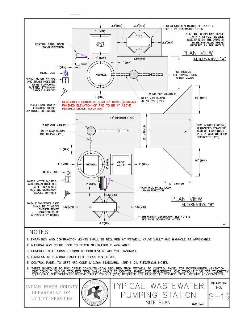
NOTE 1. LOCATION OF CONTROL PANEL PER IRCDUS INSPECTOR. 2. NATURAL GAS TO BE USED TO POWER GENERATOR IF AVAILABLE.
REINFORCED CONCRETE SLAB 6"THICK (MIN)
TURN APRON (TYPICAL)
DRAWING INDIAN RIVER COUNTY
DEPARTMENT OF UTILITIES SERVICES
TYPICAL PUMPING STATION S~o1 5 (DETAIL SHEET)-·· (A)
CONTROL PANEL DOOR SWING DIRECTION
1' (MIN)
METER BOX~ WATER METER W/ RPZ--f"Tl AND BRASS HOSE BIB W
TO BE SUPPORTED W/STEEL STANCHION
1' (MIN)
SADDLE SUPPORT;:
REINFORCED CONCRETE SLAB 6" THICK (MINIMUM) DATA FLOW TOWER FINISHED ELEVAllON OF PAD TO BE 4" ABOVE
LOCATION TO BE FINISHED GRADE ELEVAllON APPROVED BY IRCDUS
PUMP OUT MANHOLE
20 LF MAX C-900 DR-18 PVC (TYP)
WATER METER W/ RPZ----m AND BRASS HOSE BIB
TO BE SUPPORTED W/STEEL STANCHION !
SADDLE SUPPORT
DATA FLOW TOI'I1ER BASE SHALL BE 6" ABOVE 3.5'(MIN) f----~
FINSHED GRADE. LOCA llON TO BE
APPROVED BY IRCDUS
NOTES
45' MINIMUM (TYP)
===========~
z VALVE ~ 1"- VAULT -l
.....
========::::<J
EMERGENCY GENERA TOR, SEE NOTE 2 SEE S-21 GENERATOR NOTES
l
A 6' HIGH CHAIN LINK FENCE 1'11TH A 12 FOOT DOUBLE
WIDE GATE ON THE DRIVE IS TO BE INSTALLED WHERE
REQUIRED BY THE IRCDUS
PLAN VIEW ALTERNATIVE "A,I
12' MINIMUM SEE TYPICAL TURN
APRON BELOW
J PUMP OUT MANHOLE
20 LF MAX C-900 l 10' (MIN)
DR-18 PVC {TYP)
1' (MIN)
10' MINIMUM CONTROL PANEL DOOR SWING DIRECllON
TURN APRON (TYPICAL) REINFORCED CONCRETE SLAB 6" THICK {MIN) 6" X 6" WIRE MESH OR FIBERCRETE (TYP)
10' (MIN)
J PLAN VIEW
ALTERNATIVE "B"
EMERGENCY GENERA TOR, SEE NOTE 2 SEE S-21 GENERATOR NOTES
-ART-
1. EXPANSION AND CONTRACllON JOINTS SHALL BE REQUIRED AT WETWELL, VALVE VAULT AND MANHOLE AS APPLICABLE.
2. NATURAL GAS TO BE USED TO POWER GENERATOR IF AVAILABLE.
3. CONCRETE SLAB CONSTRUCTION TO CONFORM TO ACI 31B STANDARD.
4. LOCATION OF CONTROL PANEL PER IRCDUS INSPECTOR.
5. CONTROL PANEL TO MEET NEC CODE 1.10.26A STANDARD. SEE S-21, ELECTRICAL NOTES.
6. THREE SCHEDULE BO PVC CABLE CONDUITS (2"1&) REQUIRED FROM WETWELL TO CONTROL PANEL FOR POWER~NSTRUMENTATION. ONE CONDUIT (3/4"111) REQUIRED FROM VALVE VAULT TO CONTROL PANEL FOR TRANSDUCER. ONE CONDUIT 1"1&) FOR TELEMETRY EQUIPMENT. ONE SCHEDULE BO PVC CABLE CONDUIT (2"111) REQUIRED FOR ELECTRICAL SERVICE. TOTAL OF Fl (5) CONDUITS.
INDIAN RIVER COUNTY
DEPARTMENT OF
UTILITY SERVICES
TYPICAL WASTEWATER PUMPING STATION
SITE PLAN WAACH 2018
DRAWING
NO.
S-16

c JNTROL PANEL < ~EE S-18 8. S-19)
I
I
~ DOOR S'w'ING r .::::::-.::::::-.::::::-#'.::::::- TD'w'ARD 'w'ET 'w'ELL 1
.::::::
~- (2) 4' AJ UMINUM
~~~T~O<~~~~ORT I
I METER CAN--~'==='
~SERVICE DI~CONNECT I
I
3' CLEAR ZONE
CONDUIT TO POVER POLE SEE SITE PLAN
.._P...,LA_,_,_N-'-----'V--=-I=-E'w'...,_ <316 STAINL~SS STEEU ENCAStD
VARIES 3' CLEAR ZONE
316 SS U~ISTRUT BRACING 2 REQ'D. I
1~---- SERVICE I DISCONNEf T (316 SS)
CONTROL r ANEL
~GENERATOr RECEPTACLE
<2) 4' ALJUMINUM DR 316 SS v ~ SCH 40 ~UPPDRT POST <TYP)
/ - GROUND I CLAMP
I # 3/0 Br RE COPPER VIRE
FINISHED GRADE
I
2' PVC TUBE
FRONT ELEVATION
SERVICE STRUCTURE LOCATION TO BE APPROVED BY IRCDUS
REFER TO SECTION 10 SUBMERSIBLE 'w'ASTE'w'ATER
PUMPING STATION
SEE S-21 TYPICAL 'WASTE'WATER PUMP STATION ELECTRICAL NOTES
INDIAN RIVER COUNTY
DEPARTMENT OF
UTILITY SERVICES
TYPICAL \J ASTE\J ATER PUMPING STATION
ELECTRIC SERVICE ENTRANCE (METER/PANEL BOX) MAROi2018
DRA'w'ING NO.
S-17

ALARM STROBE
TERMINAL BLOCK
WHITE ~RE WAY
-1"""r"o CONTROL BREAKER
DRIP SHIELD
IOMoletQ] N
~(9 MCB ECB
EMERGENCY GENERATOR BREAKER
0 6
6 0 0 6 0
5KVA 316 STAINLESS STEEL CONTROL TRANSFORMER
REQUIRED FOR 460/480 STATIONS
CONTROL CIRCUIT BREAKER AND
DUPLEX RECEPTACLE BREAKER
PUMP CIRCUIT BREAKERS
MOTOR STARTER {20 HP OR LESS) OVER 20 HP SHALL HAVE SOFT STARTS
Til X CONTROL TERM I MALS
POLYPHASER
ALARM HORN { 4") WITH WEATHER PROOF BLACK BOX
REFER TO SECTION 10 SUBMERSIBLE WASTEWATER
PUMPING STATION
GENERATOR RECEPTACLE
ti~ ~ L CONDUIT-ALUMINUM OR
1:;1 316 SS, MYERS HUBS REQUIRED -I
C3 fg &
Ci:/ .ta C\i
SEE S-21 TYPICAL WASTEWATER PUMP STATION ELECTRICAL NOTES
INDIAN RIVER COUNTY DEPARTMENT OF UTILITY SERVICES
TYPICAL WASTEWATER DUPLEX PUMPING STATION
ELECTRIC CONTROL PANEL (BACK pANEL LAYOUT) MARQi2018
-ART-
DRAWING NO.
S-18
L
HAND/OFF /AUTO SWITCHES
INTERRUPTER
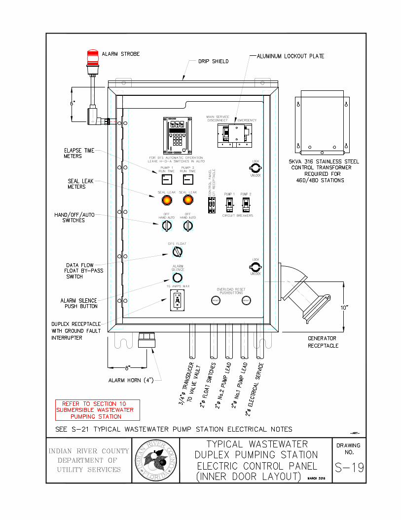
ALARM STROBE ALUMINUM LOCKOUT PLATE DRIP SHIELD
lillillil -0 888° DOD DOD
tl
.lammo • FOR DFS AUTO~ ATI C OPER ATION
LEAVE H- 0- A S\\HCHES IN AUTO
PUh!P 1 PUM P 2 RUN TIME RUN TIME
EJ EJ SEAL LEAK SEAL LEAK
0 0 OFF
HAND AUTO
® OFS FLOAT
ALARM SILENCE
a 15 AMPS MAX
rnJ]
MAIN SERVICE DISCONNECT
-'"' W-' z u <:« cc:;: <Sl'l ""' >-- 0:
LOCK
0 UNLOCK
~G: u t:~ PUMP 1 PUt.iP 2
I!! CIRCUIT BREAKERS
OVERLOAD RESET PUSH BUTTONS
LOCK
0 UNLOCK
e e
tJ S:
8
8 0 0 8 0
5KVA 316 STAINLESS STEEL CONTROL TRANSFORMER
REQUIRED FOR 460/480 STATIONS
GENERATOR RECEPTACLE
10"
j
ALARM HORN ( 4") ~ ~ ii: -.J
REFER TO SECTION 10 SUBMERSIBLE WASTEWATER
PUMPING STATION
"' ~·
.... "'
-;g .... "'
c3 fg & f;j
.&
"' SEE S-21 TYPICAL WASTEWATER PUMP STATION ELECTRICAL NOTES
INDIAN RIVER COUNTY DEPARTMENT OF UTILITY SERVICES
TYPICAL WASTEWATER DUPLEX PUMPING STATION ELECTRIC CONTROL PANEL (INNER DOOR LAYOUT) WARCH201B
-ART-
DRAWING NO.
S-19

1. Contractor shall take necessary precautions against floatation of wet well until all backfill is in place.
2. All concrete shall be class A-A (4,000 PSI for precast and 3,000 PSI for cast-in-place) unless otherwise specified.
3. Reinforcing steel shall be grade 60 fabricated and placed in accordance with ACI code splices and shall be six (6)
times the bar diameter number size or 18" minimum unless otherwise noted (STAG. SPL., TYP).
4. All backfill around the pump station site shall be compacted @ 98% of maximum density, per AASHTO-T-180.
5. Chamfer exposed concrete edges ¾" (TYP).
6. Wetwell wall shall contain a minimum of .022 sq in/linear foot reinforcement, each way top to bottom.
7. All piping at the pump station site shall be restrained.
8. All Pumps and Pumping Equipment - See IRCDUS Approved Manufacturers' Product List.
9. Stainless steel (316) cable holder shall be located on opposite side of wetwell from the influent pipe.
10. Buoyancy calculations shall be required for all pump stations along with the required pump station calculations.
11. No uni-flange pipe connections allowed.
12. Maintain minimum of 6" between any piping, fittings etc. and precast concrete.
13. Fiberglass liners shall be installed on all pump station wetwells and manholes receiving pumped sewage, plus 5
manholes in each direction.
14. All new manholes shall be coated per IRCDUS Approved Manufacturers' Product List.
15. Pump station control panel shall be provided with appropriate lightning arrestor. Verify all driven grounding grids
per N.E.C. 250.56 and SCADA (latest standards).
16. An access drive shall be provided to all IRCDUS maintained lift stations. All access drives shall be a minimum of
12' wide. If fence is installed, gate shall have a 12' opening.
17. All proposed private station owners are to sign an agreement acknowledging station is to remain private unless
subject station is constructed to IRCDUS standards.
18. Pumps shall be designed to provide a minimum pump run time equal to half the cycle time.
19. Pumps shall be designed to provide a maximum clearance of ten feet outside of lift station wetwell for future
maintenance.
20. All re-pump stations shall have bio-cube odor control systems as required by manufacturer, and approved by
IRCDUS.
21. Lift Station is to be located in a dedicated utility easement, 200' away from homes, cul-de-sacs and surface body
water.
22. A safety grate with stainless steel (316) hardware is required for all wetwells.
23. Contractor to install permanent signage with contact information and phone number at all IRCDUS and private lift
stations. Contractor to provide security for private lift stations per IRCDUS plans review. Security to include, but
not limited to, lockable hatch cover lids for the wetwell and valve pit.
24. Contractor to contact IRCDUS inspector prior to pump station construction.
25. See Drawing S-14 Plan View and S-15 Typical Pumping Station cross section. See Drawing S-16 for Typical
Pumping Station general layout and driveway. See S-17, S-18 and S-19 for electrical details.
26. Structure dimensions may vary upon approval by the IRCDUS due to buoyancy compensation or other
requirements.
27. Gate valve to be located at force main junction.
28. Stainless steel (316) lifting bails shall be used for pumps in lift stations.
29. Grinder pumps shall be a maximum of 5.0 HP unless otherwise approved by IRCDUS.
30. Electrical control panel shall conform to pump manufacturers' & SCADA system requirements.
31. Liner for all wet wells shall be HDPE or fiberglass.
32. All wet wells 15' deep or greater than 10' diameter must be approved by IRCDUS engineering.
33. Outside walls and underside of wetwell top slab and valve box shall be painted with (2) two coats
of water base epoxy.
34. All hardware to be 316 stainless steel.
35. Pump station power supply from Florida Power & Light and City of Vero Beach electric power pole or transformer
to the pump station electric panel shall be included on the Record Drawing.
36. Paint outside of walls, underside of wetwell top slab and valve vault with two coats of water base epoxy.
PUMP STATION GENERAL NOTES

1. A minimum 3' clear zone is required around the electrical area. The minimum workspace requirements shall
adhere to the National Electrical Code (NEC), Section 110.26(A).
2. A 3/4" conduit shall be installed between the control panel and the valve vault for the transducer.
3. Three (3) schedule 80, 2" conduits shall be installed between the control panel and the wet well for No. 1 pump
lead, No. 2 pump lead and the float switches.
4. All buried conduit shall be Schedule 80 PVC. All exposed conduit shall be stainless steel (316) or aluminum.
Conduit to be sealed.
5. A mastic coating is required where panel post and aluminum or stainless steel (316) conduit is in direct contact
with concrete.
6. The control panel door must open toward the wet well.
7. Electric service shall be 3 phase.
8. Alarm horn shall be sealed to prevent leakage.
9. Control panel shall be approved by IRCDUS before installation.
10. Refer to Section 10 for Pumping Station specifications.
11. Bottom of control panel to be 28" to 34" above ground.
12. All hardware and fasteners to be stainless steel (316).
13. Tools and spare parts are required (see Section 10.05).
14. Control panel shall meet the requirements of service entrance by properly bonding or shall be UL service entrance
rated.
15. Control panel shall have a data flow, float by-pass switch.
16. The maximum horsepower rating for a 120/240 volt wastewater pumping station panel is 20 HP. Any pump size
greater than 20 HP shall have 480 volt service and be designed by an electrical engineer.
17. The control panel shall be 4X NEMA, white powder coated stainless steel.
18. A water service line (1"Ø) with reduced pressure backflow preventer, water meter and hose bibb is required.
19. All penetrations into electric control panel require Meyer hubs. Corrosive materials will not be allowed.
20. Disconnect between meter and panel to be 316 stainless steel, non-fusable. Stations with generators shall be
fused.
21. Pump station control panel shall be provided with appropriate
lightning arrestor. Verify all driven grounding grids per
N.E.C. 250.56 and SCADA (latest standards
PUMP STATION ELECTRICAL NOTES
1. Housing developments of 200 or more units shall provide backup
generator sets for emergency use as required. Generator shall be
provided with automatic throw over switch that senses power
interruption from the main power source, starts the generator and
shifts the power supply to the lift station from the generator.
2. If less than 200 homes are constructed initially, but in future
phases the build-out is 200 homes are greater, an emergency
generator will be required. The pumping station shall be
constructed with space available for an emergency generator
to be installed when 200 homes are constructed.
3. IRCDUS may connect additional developments into a
proposed pumping station and may require an emergency
generator.
4. Natural gas to be used for power when available.
5. See Section 17 Engine Driven Generator Sets for
specifications.
EMERGENCY GENERATOR NOTES

0 <( 0 0:::
G-1
/R/W (TYP)
~ VALVES TO BE LOCATED REFLECTIVE MARKER I OUTSIDE EDGE OF UNPAVED
ROADS
-<t_ ROAD-- + x MAIN UNDER
_______ C::_::-ONSTRUCTION
FIRE HYDRANT
TYPICAL VALVE LOCATION FOR UNPAVED ROADS
- - <t_ ROAD--
VALVES SHALL BE LOCATED ADJACENT TO TEE OR CROSS
INDICATE DISTANCE
REFLECTIVE PAVEMENT MARKER I
(ONE REQUIRED FOR EACH VALVE)
FROM RIGHT-OF-WAY LINE AND EDGE OF PAVEMENT (TYP)
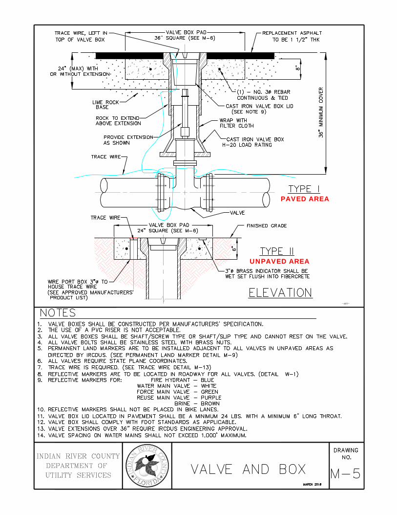
NOTES 1. VALVE SPACING ON WATER MAINS SHALL NOT EXCEED 1000'. 2. A MINIMUM COVER OF 36" IS REQUIRED ABOVE THE TOP OF ALL PIPE BELLS. 3. CONTRACTOR IS RESPONSIBLE FOR THE INSTALLATION OF BLUE REFLECTIVE MARKERS (RPM)
INDICATING A FIRE HYDRANT WHICH SHALL BE LOCATED IN THE CENTERLINE OF THE LANE CLOSEST TO THE HYDRANT.
4. DEAD END LINES, VALVES, AND HYDRANTS SHALL BE RESTRAINED. 5. ALL LINES SHALL BE A MINIMUM 1 0' OFFSET FROM BUILDINGS. 6. REFLECTIVE MARKERS (RPM'S) SHALL HAVE THE FOLLOWING COLOR SCHEMES:
FIRE HYDRANT - BLUE WATER MAIN VALVE - WHITE FORCE MAIN VALVE - GREEN REUSE MAIN VALVE - PURPLE
BRINE - BROWN
7. THE APPROPRIATE REFLECTIVE MARKER (RPM) IS REQUIRED FOR EACH VALVE. 8. NO REFLECTIVE MARKERS SHALL BE PLACED IN BIKE LANES. 9. REFLECTIVE MARKERS SHALL BE AFFIXED TO PAVEMENT WITH A FOOT APPROVED PRODUCT.
10. REFERENCE DRAWINGS M-5, VALVE AND BOX & M-6, VALVE BOX PAD.
-ART-
11. ALL FIRE HYDRANT VALVE COVERS SHALL BE PAINTED RED. ALL IN-LINE VALVES COVERS ARE TO BE PAINTED BLUE.
INDIAN RIVER CO UNTY DEPARTMENT OF UTILITY SERVICE S
FIRE HYDRANT AND VALVES (LOCATION DETAIL) MARCH2018
DRAWING NO.
W-1

6" ANCHOR COUPLING
SOUR HYDRANT GUARDS
ADDITIONAL GATE VALVE AS REQ'D BY IRCDUS REQUIRED IF DISTANCE SEE NOTE 1 IS MORE THAN 18' "" :/go·~ /
\ /®~ <®""
M.J.
M.J.
NOTES
.. 1 45'
\__ _! L~
~ MEGA-LUG "" / Q;-'f ""~
RESTRAINT OR EQUAL / ® i< / ""
'-------"<---VARIES -------'
ANCHOR TEE FOR 6" MECHANICAL JOINT 6"
PLAN VIEW
FINISHED GRADE
0(«<«<«<«<%~ DIRECT CONNECTION / (ANCHOR TYPE)
6" (MIN) ELEVA Tl ON WATER MAIN
(!)
I 0.1
1.5 CU. FT. CONCRETE
-NU-
1. HYDRANT GUARDS TO BE 4" DIAMETER GALVANIZED STEEL OR DUCTILE IRON PIPE FILLED WITH CONCRETE WHEN REQUIRED BY IRCDUS. GUARDS TO BE PAINTED RED SAME AS HYDRANT AND VALVE COVER.
2. THE HYDRANT SHOULD BE SET SUCH THAT THE "BURY LINE" ON THE HYDRANT BARREL IS SET AT FINISHED GRADE OR THAT THE OPERATING NUT OF THE PUMPER NOZZLE HYDRANT IS A MINIMUM OF 18" ABOVE FINISHED GRADE.
3. ALL HYDRANTS SHALL BE TRAFFIC BREAKAWAY TYPE. 4. COMPLETE ANCHORED FIRE HYDRANT ASSEMBLY MAY BE UTILIZED IN LIEU OF ABOVE. 5. FIRE HYDRANT SHOULD BE LOCATED A MAXIMUM OF 12' FROM EDGE OF PAVEMENT WHERE POSSIBLE. 6. ALL MATERIALS ARE TO BE PER IRCDUS APPROVED MANUFACTURERS' PRODUCT LIST. 7. TRACE WIRE TO BE INSTALLED AS PER DETAIL M-13. (TRACE WIRE NOT SHOWN IN DRAWING ABOVE.) 8. MAINTAIN 7'-6" RADIUS OF HYDRANT PERPENDICULAR TO ROADWAY OR CURB FACE (EXAMPLE
MUST BE CLEAR OF SIGNS, TREES, SHRUBS, TRANSFORMERS, UTILITY POLES, ETC.) 9. HYDRANTS AND PROTECTION DEVICES SHALL HAVE CLEARANCES OF 7'-6" IN FRONT AND TO THE SIDES
OF THE FIRE HYDRANT, WITH A 4' CLEARANCE TO THE REAR OF THE HYDRANT UNLESS THE AHJ (AUTHORITY HAVING JURISDICTION) REQUIRES A LARGER CLEAR ZONE.
10. REFERENCE DRAWINGS M-5, VALVE AND BOX & M-6, VALVE BOX PAD.
11. CONCRETE COLLAR IS REQUIRED. COLLAR SHALL BE 6" THICK x 2'x2' SQUARE AND LOCATED A
MINIMUM 2" BELOW BREAKAWAY FLANGES.
INDIAN RIVER COUNTY DEPARTMENT OF UTILITY SERVICES
FIRE HYDRANT DETAILS WAROi 2018
DRAWING NO.
W-2

FIRBERGLASS REINFORCED POLYMER (FRP) CONCRETE SOLID HEAVY DUTY TRAFFIC BEARING METER BOX LID WITH SKID RESISTANT SURFACE
VALVE BOX
APPROVED 16"x22"x18" DEEP FRP METER BOX
FINISHED GRADE 2"¢ BRASS OR PVC PLUG
2" LOCKING CURB STOP
COMPRESSION FITTING
(~~MARKER BALL
RESTRAINED
NOTES
COMPRESSION FITTING CENTER IN PLUG
ELEVATION
(SEE W-4)
1. BLOW-OFF TO BE LOCATED AT ALL DEAD END LINES AND ALIGNED WITH PROPERTY LINES AS REQUIRED BY IRCDUS.
2. ALL MATERIALS ARE TO BE PER IRCDUS APPROVED MANUFACTURERS' PRODUCT LIST.
3. METHODS OF RESTRAINT AS APPROVED BY IRCDUS.
4. TRACE WIRE TO BE INSTALLED AS PER DETAIL M-13.
-ART-
5. ELECTRONIC MARKER BALLS ARE TO BE LOCATED ADJACENT TO ALL VALVE BOXES AND PLACED
IN ALL METER BOXES WITHIN 24" FROM SURFACE.
6. ALL BLOW-OFFS SHALL BE LOCATED FROM 4'-6' OF THE TERMINAL VALVE.
INDIAN RIVE R CO UNTY DEPARTMENT OF UTILITY SERVICES
MANUAL 2" BLOW-OFF
MARa! 2018
DRAWING NO.
W-3

METERS SHALL BE LOCATED IMMEDIATELY------------------1
OTHERWISE DIRECTED BY IRCDUS INSIDE THE RIGHT-OF-WAY UNLESS MARKER PAINTED BLUElJn
ETCH CURB WITH "W" FOR FIBERGLASS REINFORCED POLYMER (FRP) CONCRETE I : WATER SERVICE SOLID HEAVY DUTY TRAFFIC BEARING METER BOX LID I~
WITH SKID RESISTANT SURFACE, LIFT SLOT & 316 SS PIN II II ::J SEE NOTE 11. 1>-
1 I ~ SEE W-7 PRE-PLUMBED METER BOX ~ I I ~
1 ", 1~", OR 2'' CORP STOP
90' ANGLE CURB STOP I 1 ~
FINISHED 12
.. 1 1 o_
LONG SERVICE I ._.,_____/'----------'•
PVC CASING SLEEVE MAIN
DOUBLE STRAP SERVICE SADDLE
NOTES
TRACE WIRE (SEE NOTE 8)
ELEVATION
4" MARKER BALL INSIDE BOTTOM OF ALL METER BOXES
RUBBER GASKET REQ'D SEE W-7
1. SUCCESSIVE TAPS INTO THE WATER MAIN SHALL BE A MINIMUM OF 18" ON CENTER.
2. ALL SERVICES REQUIRE 36" MINIMUM COVER.
I I I I
-ART-
3. MINIMUM SERVICE SIZE SHALL NOT BE LESS THAN 1''¢, DUAL SERVICES SHALL BE A MINIMUM 1-1/2"¢, TRIPLE SERVICES SHALL BE A MINIMUM 2"¢ AND QUADRUPLE SERVICES SHALL BE APPROVED BY IRCDUS.
4. 1 "¢ & 1-1 /2"¢ LONG SERVICES REQUIRE A 2" MINIMUM I. D. SLEEVE. 2"¢ LONG SERVICES REQUIRE A 3" MINIMUM I.D. CASING SLEEVE. CASING SLEEVE SHALL BE SCHEDULE 40 P.V.C.
5. ALL METERS 2"¢ OR SMALLER SHALL BE SUPPLIED AND INSTALLED BY IRCDUS. ALL METERS GREATER THAN 2"¢ SHALL BE SUPPLIED AND INSTALLED BY THE DEVELOPER/PROPERTY OWNER. REFER TO APPROVED MANUFACTURERS' PRODUCT LIST FOR METERS GREATER THAN 2"¢.
6. PIN LOCKS WITH PLASTIC DUST CAPS SHALL BE PURCHASED BY THE DEVELOPER AND/OR CONTRACTOR AND SHALL BE INSTALLED ON ALL LOCKING CURB STOPS INSIDE METER BOX, SAMPLING POINTS, AND WATER SERVICE CONNECTIONS AT THE TIME OF ACTIVATING ALL WATER MAINS OR AT SUCH TIME AS DIRECTED BY IRCDUS.
7. CURB STOPS SHALL BE THE SAME SIZE AS THE METERS THAT ARE INSTALLED.
8. TRACE WIRE TO BE INSTALLED AS PER DETAIL M-13.
9. PLACE A 4" ELECTRONIC MARKER BALL INSIDE BOTTOM OF ALL METER BOXES.
10. ALL RESIDENTIAL AND ONE ERU SERVICES SHALL BE 5/8" METERS.
11. ALL METER BOXES TO BE PER IRCDUS APPROVED MANUFACTURERS' PRODUCT LIST.
INDIAN RIVER COUNTY DEPARTMENT OF UTILITY SERVICES
WATER SERVICE (INSIDE RIGHT-OF-WAY)
WARQl 2018
DRAWING NO.
W-4

1", 1~". OR 2" CORP STOP
BRASS DOUBLE STRAP SERVICE SADDLE
SEE NOTES W-4
WHEN METERS CAN NOT BE LOCATED -----. IMMEDIATELY INSIDE THE RIGHT OF WAY THEY MAY BE LOCATED INSIDE THE PROPERTY LINE AS DIRECTED BY IRCDUS
w z ::J
>-1-
90" ANGLE LOCKING CURB STOP----.. 0::: w
I~
APPROVED METER BOXES SHALL BE POLYMER CONCRETE & FIBERGLASS WITH NO HOLE LID (BALL VALVE TYPE TO ACCOMMODATE
5/8"¢x3/4"¢ METER)
SIDEWALK
TRACE WIRE
LONG SERVICE
PVC CASING SLEEVE (EXTEND UNDER SIDEWALK)
ELEVATION
INDIAN RIVER COUNTY DEPARTMENT OF
UTILITIES SERVICES
MARKER BALL
a..
w
13 >-1-0:::
FINISH GRADE
w IN UNE DUAL CHECK a.. BY IRCDUS 0 0::: a..
LINE SETIER (TYP) (SEE NOTE 11, W-4)
WATER SERVICE (OUTSIDE OF RIGHT OF WAY)

WHEN METERS CANNOT BE LOCATED IMMEDIATELY INSIDE THE RIGHT OF WAY THEY MAY BE LOCATED INSIDE THE PROPERTY LINE AS DIRECTED BY IRCDUS
FIBERGLASS REINFORCED POLYMER (FRP) CONCRETE ----... SOLID HEAVY DUTY TRAFFIC BEARING METER BOX LID WITH SKID RESISTANT SURF ACE, LIFT SLOT & 316 SS PIN
w z :::J
>f--0:: w
I~ 0:: D....
ETCH CURB WITH "W" FOR WATER SERVICE
SEE W-7 PRE-PLUMBED METER BOX--------..
1'', 1 1/2" OR 2" CORP STOP
WATER MAIN
DOUBLE STRAP SERVICE SADDLE
SEE NOTES W-4
90" ANGLE CURB STOP------..
5'-0"
SIDEWALK
(ITRACE WIRE _i_ (SEE DETAIL M-13)
- ~----
LONG SERVICE
PVC CASING SLEEVE (EXTEND UNDER SIDEWALK
PER IRCDUS)
ELEVATION
INDIAN RIVER COUNTY DEPARTMENT OF UTILITY SERVICES
~I 5;
J_l 0 I
f-I (_')
0::
FINISHED GRADE
4" MARKER BALL INSIDE BOTTOM ALL METERS
RUBBER GASKET REQ'D SEE W-7
WATER SERVICE (OUTSIDE RIGHT-OF-WAY)
-ART-

PROPERTY LINE~ RIGHT-OF-WAY LINE I
1-1/2"¢ P.E SERVICE LATERAL
CUSTOMER PIPING
* BRASS COMPRESSIONJ
LOCKING WYE BRANCH CURB STOP
SINGLE SERVICE pLAN VIEW DUAL SERVICE
IRCDUS MAY REQUIRE RADIO READ LID METER
BRASS LOCKING CURB STOP
SET METER BOX FLUSH WITH FINISHED GRADE
CHECK VALVE
WITH INTEGRAL METER COUPLING
,........, z :::2 0::: '--'w • > <D 0 n u
<D
~ 0 :z w w (/)
90" ANGL~ CURB STOP
RUBBER GASKET REQ'D SEE W-7
NOTES
· .. · -~.:.:· ... . . .. .. . .. . . . . . 4': MARKER. BALL .INSIDE •
BOTTOM OF ALL METER BOXES
1"¢ (MIN) CUSTOMER PIPING (BY OTHERS)
ELEVATION
I • •
• • • •
1. METERS OVER 2"¢ MUST BE APPROVED BY IRCDUS AND SHALL BE SUPPLIED AND INSTALLED BY THE DEVELOPER/PROPERTY OWNER.
2. ALL METERS 2"¢ AND SMALLER WILL BE SUPPLIED AND INSTALLED BY IRCDUS.
3. MINIMUM SIZE OF METER BOXES: 1 "¢ SERVICE (12" X 18"); 1-1 /2"¢ AND 2"¢ SERVICE (17" X 28").
4. TRACE WIRE (NOT SHOWN) TO BE INSTALLED AS PER DETAIL M-13. 5. PLACE A 4" ELECTRONIC MARKER BALL IN THE INSIDE BOTTOM OF ALL METER BOXES.
6. ALL METER BOXES SHALL BE PER IRCDUS APPROVED MANUFACTURERS' PRODUCT LIST.
INDIAN RIVER COUNTY
DEPARTMENT OF
UTILITY SERVICES METER BOX
MARCH 2018
I
-NOT-
DRAWING NO.
W-6

W-6
NOTES
DRAWING
NO.
CUSTOMER RESPONSIBLE FOR PIPING
FLOW
(FOR CONSTRUCTION)
TEMPORARY HOSE BIBB
FLOW
TEMPORARY HOSE BIBB
ON CUSTOMER SIDE OF METER
A
1. PER RESOLUTION No. , IRCDUS TO INSTALL A TEMPORARY HOSE BIBB TO SUPPLY METERED
WATER FOR CONSTRUCTION.
2. PRIOR TO FINAL IRCDUS INSPECTION, THE CONTRACTOR SHALL REMOVE THE TEMPORARY HOSE BIBB
AND MAKE WATER CONNECTION TO THE BUILDING PER CURRENT IRCDUS CONSTRUCTION STANDARDS.
3. CONTRACTOR SHALL NOT DISTURB FITTINGS AT METER BOX.
4. CONTRACTOR SHALL REMOVE BIBB RISER AND CONNECT PERMANENT SERVICE AT LOCATION INDICATED.
CUT IN PERMANENT SERVICE
AT THIS POINT
w/ WATTS ANTI-SIPHON
DEVICE (3/4")

FIBERGLASS REINFORCED POLYMER <FRP) CONCRETE LID ~ITH SKID RESISTANT SURFACE
/. ~
t-IH(tt~ tl(7;n It-if>.. .II ~ v~
I ~ /:
L I I SEE DETAIL A
TOP VIE'w'
FIBERGLASS REINFORCED POLYMER <FRP) CONCRETE, PRE-PLUMBED METER BOX
PRE-INSTALLED 'YIATER TIGHT GASKET
HINGED CAST IRON METER BOX LID
~ SOLID METER BOX LID SEE NOTE 3
DRAIN HOLES
RUBBER GASKET <BOTH SIDES)
SECTION VIE'w'
NOTES
METER BOX 'w'ITH LID
3/4' NIPPLE
3/4 • IN LINE CHECK VALVE
CURB STOP
3/41 NIPPLE
l'x 7 112' SCH. 80 PVC IDLER
DETAIL ''A"
1. PRE-PLUMBED METER BOXES PER IRCDUS APPROVED MANUFACTURER'S PRODUCT LIST.
2. DIMENSIONS OF PRE -PLUMBED METER BOXES 'WILL VARY BET 'WEEN MANUFACTURERS.
3. SOLID METER BOX LIDS SHALL BE HEAVY DUTY TRAFFIC BEARING 'YIITH A SKID RESISTANT
SURF ACE, A LIFT SLOT AND STAINLESS STEEL <316) LIFTING PIN.
-ART-
4. METER BOX LIDS 'WITH RADIO READ LIDS MAY BE REQUIRED BY IRCDUS. NOT SHO'YIN IN DRA'YIINGS.
INDIAN RIVER COUNTY DEPARTMENT OF UTILITY SERVICES
TYPICAL PRE-PLUMBED METER BOX (ENCLOSED) H~2Dll
DRA'WING NO.
w-7

I IUL..I\'-'L..M~~ 1\L...II"'I Vl\vL..U I VL.. IIVIL..I\ \I 1\1 J vVI"'vi\L.. I L.. L..IU
WITH SKID RESISTANT SURFACE
TOP VIEW
FIBERGLASS REINFORCED POLYMER (FRP) CONCRETE, OPEN BOTTOM METER BOX
/") / /
/ / / /
/ / / /
fllllZlZllTA / ??l/1 HINGED CAST IRON METER BOX LID
= SOLID METER BOX LID SEE NOTE 3
~···<;n~ ~ ~11
( 1 I I I
J) lL
NOTES
LINE SETTER (TYP)
SECTION VIEW
METER BOX WITH LID
1. OPEN BOTTOM METER BOXES PER IRCDUS APPROVED MANUFACTURER'S PRODUCT LIST.
2. DIMENSIONS OF PRE-PLUMBED METER BOXES WILL VARY BETWEEN MANUFACTURERS.
3. SOLID METER BOX LIDS SHALL BE HEAVY DUTY TRAFFIC BEARING WITH A SKID RESISTANT
SURFACE, A LIFT SLOT AND STAINLESS STEEL (316) LIFTING PIN.
-ART-
4. METER BOX LIDS WITH RADIO READ LIDS MAY BE REQUIRED BY IRCDUS. NOT SHOWN IN DRAWINGS.
5. LINE SETTER PER IRCDUS APPROVED MANUFACTURES' PRODUCT LIST.
IND IAN RIVER COUNTY DEPARTMENT OF UTILITY SERVICES
TYPICAL PRE-PLUMBED METER BOX
(OPEN BOTTOM) M~2m8
DRAWING NO.
W-7 A

A CORPORATION STOP SHALL BE INSTALLED ~ITH A LENGTH OF 1'¢ COPPER TUBING EXTENDING ABOVE THE FINISHED GRADE. THE TUBING SHALL BE INSTALLED ~ITH A 180• DD~NTURN BEND.
1' BALL VALVE
" ru ~ ..... ~ FINISHED
~ w > D u
NOTES
GRADE
~ATER MAIN
ELEVATION
1'¢ COPPER TUBING
. '<t C\J
CORPORATION STOP CCDNTRACTDR TO PLUG ~HEN ABANDONING SAMPLE POINT)
BRASS DOUBLE STRAP TAPPING SADDLE
-ART-
1. TEMPORARY SAMPLING POINT SHALL BE CONSTRUCTED OF SCHEDULE 40 PVC PIPE DR OTHER MATERIALS AS APPROVED BY IRCDUS.
2. NO SAMPLE POINT SHALL BE CONSTRUCTED ON FIRE HYDRANTS. 3. CERTIFICATION OF PRESSURE TEST, T~D CONSECUTIVE DAYS OF SUCCESSFUL BACTERIOLOGICAL
TESTS, AND CLEARANCE FROM THE FLORIDA DEPARTMENT OF ENVIRONMENTAL PROTECTION IS REQUIRED BEFORE THE SAMPLE TAP CAN BE ABANDONED.
4, ~HEN SAMPLING IS COMPLETE, TUBING SHALL BE REMOVED AND CORPORATION STOP PLUGGED.
INDIAN RIVER COUNTY DEPARTMENT OF UTILITY SERVICES
TEMPORARY SAMPLING POINT (BACTERIOLOGICAL)
MAI'CH 2018
DRA~ING
NO.
w-8

PIPE 8c FITTINGS SHALL BE USED FOR FULL FLO~ FLUSHING
VALVE PAD TO BE CONSTRUCTED AFTER ~ATER MAIN HAS BEEN FLUSHED AND FLUSHING ASSEMBLY HAS BEEN REMOVED
NE~ ~ATER MAIN TO BE FLUSHED FOR ENTIRE LENGTH
EXISTING ~ATER MAIN
ELEVATION
NOTES
TEMPORARY CONNECTION
SEE NOTE 7
-ART-
1. A FULL BORE FLUSH IS THE ONLY FLUSHING METHOD APPROVED FOR MAINS. ALL FIRE HYDRANTS AND DETECTOR CHECK VALVES SHALL BE INSPECTED AND TESTED TO ENSURE THAT NO FOREIGN OBJECTS IMPEDE THE FLOW OF WATER. FOR DETAILS ON LINE FILLING, SEE W-14.
2. A PRESSURE GAUGE SHALL BE INSTALLED UPSTREAM OF THE FLUSHING POINT. PRESSURE UPSTREAM SHALL NOT FALL BELOW 20 P.S.I.
3. PROVIDE ALL NECESSARY JOINT RESTRAINTS SUCH AS MEGALUGS, RESTRAINED JOINT HARNESS, OR APPROVED EQUAL IN ACCORDANCE WITH IRCDUS STANDARDS. SEE M-3
4. IRCDUS PERSONNEL, AFTER A MINIMUM OF A 48 HOUR NOTICE BY THE CONTRACTOR, SHALL BE PRESENT FOR ALL FLUSHING ACTIVITIES AND SHALL OPERATE ALL EXISTING VALVES.
5. FOR TRANSMISSION MAINS 12" DIAMETER OR LARGER, "PIGGING" IS REQUIRED. 6. TEMPORARY CONNECTION FOR FLUSHING SHALL BE SAME DIAMETER PIPE AS THE NEW MAIN AND VALVE. 7. CONTRACTOR SHALL PROVIDE ADEQUATE PROTECTION AGAINST EROSION DOWNTSTREAM OF EXIT PIPE DURING
FLUSHING OF MAIN TO MEET THE APPROVAL OF IRCDUS. 8. WHEN FLUSHING IS COMPLETE, THE TEMPORARY FLUSHING ASSEMBLY SHALL BE REMOVED AND THE GATE
VALVE SHALL BE PLUGGED. 9. FIELD INSPECTION BY IRCDUS IS REQUIRED BEFORE UTILITIRS ARE ACCEPTED.
INDIAN RIVER COUNTY DEPARTMENT OF UTILITY SERVICES
DRAWING
FULL BORE NO.
FLUSHING CONNECTION W-9 MAROi :l01B
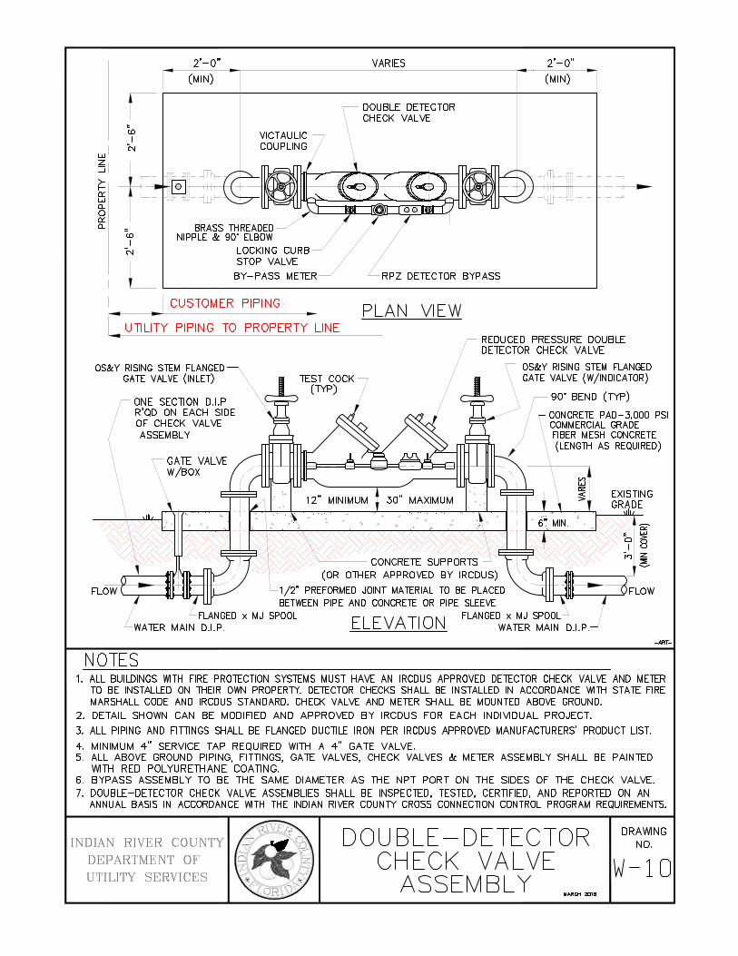
2'-0"
(MIN)
t-tO I
w l 'N
s1 +-->-f-0:: w I~-[1_
0 0:: [1_
"(!) BRASS THREADED I
NIPPLE & 90' ELBOW -C'l LOCKING CURB
L STOP VALVE
BY-PASS METER
... ..1 CUSTOMER PIPING .. I ... UTILITY PIPING TO PROPERTY LINE
OS&Y RISING STEM FLANGED GATE VALVE (INLET)
ONE SECTION D.I.P R'QD ON EACH SIDE OF CHECK VALVE ASSEMBLY
WATER MAIN D.I.P.
NOTES
VARIES
DOUBLE DETECTOR CHECK VALVE
2'-0"
(MIN)
-rfn---:;~·- - - ~ -~
RPZ DETECTOR BYPASS
PLAN VIEW
ELEVATION
REDUCED PRESSURE DOUBLE DETECTOR CHECK VALVE
OS&Y RISING STEM FLANGED GATE VALVE (W/INDICATOR)
)\
go· BEND (TYP)
CONCRETE PAD-3,000 PSI COMMERCIAL GRADE FIBER MESH CONCRETE (LENGTH AS REQUIRED)
WATER MAIN D.I.P. -ART-
1. ALL BUILDINGS WITl1 FIRE PROTECTION SYSTEMS MUST HAVE AN IRCDUS APPROVED DETECTOR CHECK VALVE AND METER TO BE INSTALLED ON THEIR OWN PROPERTY. DETECTOR CHECKS SHALL BE INSTALLED IN ACCORDANCE WITl1 STATE FIRE MARSHALL CODE AND IRCDUS STANDARD. CHECK VALVE AND METER SHALL BE MOUNTED ABOVE GROUND.
2. DETAIL SHOWN CAN BE MODIFIED AND APPROVED BY IRCDUS FOR EACH INDIVIDUAL PROJECT.
3. ALL PIPING AND FITTINGS SHALL BE FLANGED DUCTILE IRON PER IRCDUS APPROVED MANUFACTURERS' PRODUCT LIST.
4. MINIMUM 4" SERVICE TAP REQUIRED WITH A 4" GATE VALVE. 5. ALL ABOVE GROUND PIPING, FITTINGS, GATE VALVES, CHECK VALVES & METER ASSEMBLY SHALL BE PAINTED
WITH RED POLYURETHANE COATING. 6. BYPASS ASSEMBLY TO BE THE SAME DIAMETER AS THE NPT PORT ON THE SIDES OF THE CHECK VALVE. 7. DOUBLE -DETECTOR CHECK VALVE ASSEMBLIES SHALL BE INSPECTED, TESTED, CERTIFIED, AND REPORTED ON AN
ANNUAL BASIS IN ACCORDANCE WITH THE INDIAN RIVER COUNTY CROSS CONNECTION CONTROL PROGRAM REQUIREMENTS.
INDIAN RIVER COUNTY DEPARTMENT OF UTILITY SERVICES
DOUBLE- DETECTOR CHECK VALVE
ASSEMBLY WARQi 2018
DRAWING NO.
W-10

REDUCED PRESSURE----.. BACKFLOW PREVENTER (RPZ) WITH RISING STEM GATE VALVES
NOTES
TEST PORT
PLAN VIEW
FINISHED GRADE
-ART-
1. ALL BUILDINGS WITH FIRE SPRINKLER PROTECTION SYSTEMS INCLUDING COMMERCIAL, SINGLE FAMILY RESIDENTIAL AND MULTI-STORY, MULTI-FAMILY ARE REQUIRED TO INSTALL A DOUBLE CHECK BACKFLOW PREVENTER WITH A REDUCED PRESSURE ZONE (RPZ) FEATURE AS DETERMINED BY IRCDUS.
2. ALL FASTENERS SHALL BE 316 STAINLESS STEEL (OR APPROVED EQUAL).
3. APPROVED EQUALS HAVING FULL UL, NSF, USC, AND AWWA CERTIFICATIONS MAY BE INSTALLED ONLY AFTER SPECIFIC APPROVAL BY IRCDUS.
4. SUPPORT BACKFLOW PREVENTER FROM WALL, IF REQUIRED, WITH APPROVED PIPE SUPPORT SYSTEM. PIPE SUPPORT SYSTEM SHALL BE BRASS, COPPER OR D.I.P., AS APPROVED BY IRCDUS.
5. PIPING 2-1/2" OR GREATER SHALL BE FLANGED DUCTILE IRON PIPE.
6. ALL MATERIALS ARE TO BE PER IRCDUS APPROVED MANUFACTURERS' PRODUCT LIST.
7. RPZ'S SHALL BE INSPECTED, CERTIFIED AND REPORTED ON AN ANNUAL BASIS IN ACCORDANCE WITH THE INDIAN RIVER COUNTY CROSS CONNECTION CONTROL PROGRAM REQUIREMENTS.
INDIAN RIVER COUNTY DEPARTMENT OF UTILITY SERVICES
REDUCED PRESSURE DRA~NG NO.
BACKFLOW PREVENTER w- 11 ( R p z ) WARCH ~18

FLOAT S~ITCH CABLE (TO CONTROL PANEL>
-E CD -
IJIRE (TO PLUG VALVE IJITH ELECTRIC ACTUATOR> GRATING
FLOAT S~ITCH (EMERGENCY DVERFLD~ CUTOFF>
LEVEL SENSDR-METRITAPE
HIGH W'ATER LEVEL .. LAKE DR POND
2'x2' PREFAB CONCRETE BOX CULVERT ELEVATION
CONCRETE
(RJ>
DIP <TYP>
EXISTING GRADE
LAKE DR POND
NOTES 1. ALL ABOVE GROUND PIPING SHALL BE PAINTED PANTDNE PURPLE (522C). 2. PROVIDE A PLACARD ~ITH THE ~DRDS 'RECLAIMED WATER IN USE.'
3. ALL MATERIALS ARE TO BE PER IRCDUS APPROVED MANUFACTURERS' PRODUCT LIST. 4. DISCHARGE INVERT TO BE ONE PIPE DIAMETER ABOVE METER TO MAINTAIN FULL PIPE.
5. A TELEMETRY AND MONITORING DEVISE IS REQUIRED AT DISCHARGE. TO BE INSTALLED IN STRICT ACCORDANCE WITH MANUFACTURERS INSTRUCTIONS.
INDIAN RIVER COUNTY
DEPARTMENT OF
UTILITIES SERVICES
REUSE PIPE DISCHARGE DETAIL
~1!1111
DRAWING NO.
\v'-11 A

nn 1n
~¥----ill1 l-HH-++1++---l•C+ FLOW '---
I
CONCRETE PAO
1
,,000 PSI COMMERCIAL G~DE FIBER MESH COI!ICRETE
(LENGTH I'S REQUIRED)
36" (MIN)
OBSTACLE (LANDSCAPING, FENCE, ETC.)
36" (MIN) CLEARANCE FROM INFRASTRUCTURE
PLAN VIEW
VALVES WITH RISING STEM (TYP) 5 REQUIRED
BACKFLOW PREVENTER (RPZ)
IRCDUS ---~~------ CUSTOMER RESPONSIBILITY CUSTOMER SHALL BE RESPOSIBLE FOR ALL .,.I,. --- MAINTENANCE WITH THE EXCEPTION OF THE METER WHICH IS THE PROPERlY OF IRCDUS
DUCTILE IRON
ALL PIPE AND 1 TnNGS SHALL BE FLAN ED CONCRETE PAD-3,000 PSI COMMERCIAL GRADE FIBER MESH CONCRETE
-FLOW
'--~-FLANGED PIPE & FITTINGS (2 REQUIRED TYP)
FLANGED x CONNEC11NG MJ SPOOL FLANGED x CONNEC11NG MJ SPOOL
BY-PASS NOT SHOWN FOR CLARITY
ELEVATION
NOTES 1. ALL ABOVE GROUND PIPING SHALL BE FLANGED DUCTILE IRON.
ONE SECTION D.I.P R'QD ON EACH SIDE OF CHECK VALVE ASSEMBLY
2. FIELD FABRICATED FLANGES MUST BE APPROVED BY IRCDUS ENGINEERING . .3. DEVICE TO BE INSTALLED IN STRICT ACCORDANCE WITH MANUFACTURER'S INSTRUCTIONS.
-AAT-
4. ASSEMBLY TO BE PRIMED WITH RUST INHIBITIVE PRIMER AND FINISHED PAINTED BLUE AFTER INSTALLATION. (SEE APPROVED MANUFACTURERS' PRODUCT LIST)
5. BY-PASS PIPE DIAMETER SHALL BE SAME SIZE AS MAIN PIPE. 6. TO SECURE VALVES: CUSTOMER TO SUPPLY GALVANIZED CHAIN, IRCDUS TO SUPPLY LOCK.
7. RPZ'S SHALL BE INSPECTED, CERTIFIED AND REPORTED ON AN ANNUAL BASIS IN ACCORDANCE WITH THE INDIAN RIVER COUNTY CROSS CONNECTION CONTROL PROGRAM REQUIREMENTS.
INDIAN RIVER COUNTY DEPARTMENT OF UTILITY SERVICES
MASTER COMBINATION
METER ASSEMBLY
(.3" OR LARGER) WAACH 2018
DRAWING NO.
W-12

NOTES:
1. A temporary jumper connection is required at all connections between existing active
water mains and proposed new water main improvements.
2. The Temporary Jumper Detail (W-12) is to be used for filling any new water main of any
size from the existing active water mains and for the flushing of new mains up to 6”
diameter (2.5 FPS minimum velocity) and for pulling bacteriological samples from any
new water main of any size.
3. The jumper connection shall be maintained until after the filling, flushing, testing and
disinfection of the new main has been successfully completed and clearance for use from
the Florida Department of Environmental Protection (FDEP) and other pertinent agencies
has been received. Adequate thrust blocking and/or restraints shall be provided
temporarily, as required.
4. Pipe and fittings used for connecting the new pipe to the existing pipe shall be disinfected
prior to installation in accordance with AWWA C651, LATEST EDITION. The tapping
sleeve and exterior of the main to be tapped shall be disinfected by spraying or swabbing
per section Two of AWWA C651. The use of tablets is strictly prohibited.
5. The Jumper connection shall also be used to maintain a minimum pressure of 20 PSI in
the new mains continuously after disinfection and until FDEP clearance letter is obtained.
6. The Contractor shall provide documentation demonstrating that the double check
backflow prevention device is in good working order at the time of installation, and
provide documentation that the double check backflow prevention device has been tested
in the last 12 months, and is in good working order one year from installation by a
qualif ied backflow technician as approved by IRCDUS.
7. Except as required to flush lines greater than 6” diameter, the tie-in valve shall remain
closed and shall be locked in the closed position by the utility company. The tie-in valve
shall remain locked closed until the new system has been cleared for use by the FDEP
and all other pertinent agencies.
8. Upon receipt of clearance for use by FDEP and all other pertinent agencies, the
Contractor shall remove the temporary jumper connection. The corporation stops are to
be closed and plugged with 2” brass or PVC stops.
9. All installation and maintenance of the temporary jumper connection and associated
backflow prevention device, fit tings, valves, etc., shall be the responsibility of the
Contractor.
10. If the water main to be flushed is greater than 6” diameter or such length that a full pipe
flush at the 2.5 FPS velocity cannot be accomplished, the following procedure shall be
utilized.
a) Install pressure gauges as indicated on Temporary Jumper Detail (W-11).
b) Open all downstream valves in the new system prior to flush.
c) Flush new water main thru tie-in valve maintaining a 10+/- PSI pressure
differential between gauges during flush.
d) IRCDUS personnel, in the presence of the Engineer of Record shall operate tie-
in valve to insure that the required pressure differential is maintained.

”

TEMPORARY JUMPER DETAIL NOTES
CONTINUED FROM W-13
9. Pipe and fittings used for connecting the new pipe to the existing pipe shall be disinfected with liquid chlorine
prior to installation in accordance with AWWA C651, LATEST EDITION. The tapping sleeve and exterior of
the main to be tapped shall be disinfected by spraying or swabbing per AWWA C651 Section Two. The use of
chlorine tablets is strictly prohibited.
10. The jumper connection shall also be used to maintain a minimum pressure of 20 PSI in the new mains
continuously after disinfection and until FDEP clearance letter is obtained.
11. The Contractor shall provide documentation demonstrating that the Reduced Pressure Zone Backflow
Preventer (RPZ) is in good working order at the time of installation, and provide documentation that the RPZ
has been tested by a qualified backflow technician as approved by IRCDUS. The Contractor shall have each
RPZ tested prior to use on each project.
12. Except as required to flush lines greater than 6” diameter, the tie-in valve shall remain closed and shall be
locked in the closed position by the utility company. The tie-in valve shall remain locked closed until the new
system has been cleared for use by the FDEP.
13. If the water main to be flushed is greater than 6” diameter or such length that a 2.5 FPS velocity cannot be
accomplished by flow through the temporary jumper, the following procedure shall be utilized:
a. Install pressure gauges as indicated on Temporary Jumper Detail (W-13).
b. Open all downstream valves in the new system prior to flush.
c. IRCDUS personnel in the presence of the Engineer of Record shall operate tie-in valve to insure that the
required upstream pressure is maintained.
d. Flush new water main thru tie-in valve maintaining a minimum 20 PSI pressure in the upstream main.
14. The jumper connection shall be maintained until after the filling, flushing, testing and disinfection of the new
main has been successfully completed and clearance for use from the Florida Department of Environmental
Protection (FDEP) and other pertinent agencies has been received. Adequate restraints shall be provided, as
required.
15. Upon receipt of clearance for use by FDEP, the Contractor shall remove the temporary jumper connection.
The corporation stops are to be closed and plugged with 2” brass or PVC plugs.

III – SPECIFICATIONS

Section 1
Water Mains - Ductile Iron Pipes (DIP) and Fittings
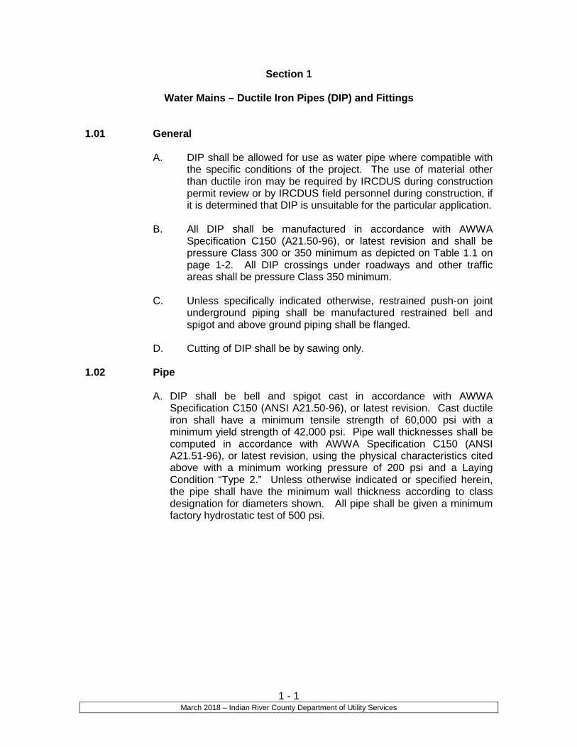
1 - 1 March 2018 – Indian River County Department of Utility Services
Section 1
Water Mains – Ductile Iron Pipes (DIP) and Fittings 1.01 General
A. DIP shall be allowed for use as water pipe where compatible with the specific conditions of the project. The use of material other than ductile iron may be required by IRCDUS during construction permit review or by IRCDUS field personnel during construction, if it is determined that DIP is unsuitable for the particular application.
B. All DIP shall be manufactured in accordance with AWWA
Specification C150 (A21.50-96), or latest revision and shall be pressure Class 300 or 350 minimum as depicted on Table 1.1 on page 1-2. All DIP crossings under roadways and other traffic areas shall be pressure Class 350 minimum.
C. Unless specifically indicated otherwise, restrained push-on joint
underground piping shall be manufactured restrained bell and spigot and above ground piping shall be flanged.
D. Cutting of DIP shall be by sawing only.
1.02 Pipe
A. DIP shall be bell and spigot cast in accordance with AWWA Specification C150 (ANSI A21.50-96), or latest revision. Cast ductile iron shall have a minimum tensile strength of 60,000 psi with a minimum yield strength of 42,000 psi. Pipe wall thicknesses shall be computed in accordance with AWWA Specification C150 (ANSI A21.51-96), or latest revision, using the physical characteristics cited above with a minimum working pressure of 200 psi and a Laying Condition “Type 2.” Unless otherwise indicated or specified herein, the pipe shall have the minimum wall thickness according to class designation for diameters shown. All pipe shall be given a minimum factory hydrostatic test of 500 psi.

1 - 2 March 2018 – Indian River County Department of Utility Services
Table 1.1 Pressure Class 300 and 350
1.03 Fittings
A. All underground fittings shall be either push-on, restrained, or mechanical joint. Mechanical joints shall conform to AWWA Specification C110 (ANSI 21.10-98) or C153 (ANSI 21.53-00), or latest revisions. All aboveground fittings shall be flanged joint.
B. The pressure rating shall be 350 psi (Class 350 Pipe).
C. Joint restraints, when required, shall be in accordance with
IRCDUS Approved Manufacturers’ Products List or an approved equal.
D. All fittings shall be lined with the same material as specified for the pipe as per paragraph 1.04.
1.04 Lining and Coating
A. Unless otherwise indicated, all DIP shall be factory lined and coated.
B. All pipe shall be cement mortar lined and seal coated in
accordance with AWWA Standard C104 (ANSI A21.4-95), or latest revision unless double lining is required by IRCDUS.
Nominal Size
Diameter (Inches)
Actual Outside
Diameter (Inches)
300 psi Wall
Thickness (Inches)
350 psi Wall
Thickness (Inches)
3 3.96 --- 0.25 4 4.80 --- 0.25 6 6.90 --- 0.25 8 9.05 --- 0.25
10 11.10 --- 0.26 12 13.20 --- 0.28 14 15.30 0.30 0.31 16 17.40 0.32 0.34 18 19.50 0.34 0.36 20 21.60 0.36 0.38 24 25.80 0.40 0.43 30 32.00 0.45 0.49 36 38.30 0.51 0.56 42 44.50 0.52 0.63 48 50.80 0.64 0.70 54 57.56 0.72 0.79 60 61.61 0.76 0.83 64 65.67 0.80 0.87

1 - 3 March 2018 – Indian River County Department of Utility Services
C. Unless specified otherwise, all ductile iron pipe shall be bituminous coated outside to a dry film thickness of at least 1 mil.
D. Anywhere that the coating is removed purposely or accidentally,
the area shall be cleaned of any rust, grease, and dirt and re-coated to a minimum dry film as specified for the individual piece.
E. If and where directed by IRCDUS’s Engineer, a polyethylene
encasement shall be provided around pipe, fittings, and valves. The material, installation, and workmanship shall conform to applicable sections of AWWA C105 (ANSI A21.5-99), or latest revision. Installation methods A or B shall be employed using flat tube polyethylene. The Contractor shall make provisions to keep the polyethylene from direct exposure to sunlight prior to installation. Backfilling following installation shall be completed without delay to avoid exposure to sunlight.
F. All exposed (i.e. aerial crossings) DIP water mains shall be primed
and painted “blue” as per IRCDUS Approved Manufacturers’ Products List or equal.
1.05 Bell and Spigot Connections
A. Joints in bell and spigot pipe shall be push-on, mechanical, or restrained joints in accordance with AWWA Standard C111 (ANSI 21.11-00), or latest revision. Pipe restraints shall also be in accordance with IRCDUS Standards or as directed by IRCDUS’s Engineer.
1.06 Flanged Connections
A. All flanged pipe barrels shall comply with the physical and chemical requirements as set forth in the Handbook of DIP of the Cast Iron Pipe Research Association, latest revisions. Flanges shall be in accordance with ANSI Specification B16.1 for Class 125 flanges. Bolts shall comply with ANSI Specification B18.2.
B. Flanged pipe shall be faced and drilled to the American Standard
Drilling, unless special drilling is called for or required. Where tap or stud bolts are required, flanges shall be tapped. Flanges shall be accurately faced and drilled smooth and true, at right angles to the pipe axis and shall be covered with zinc dust and tallow or a rust preventive compound immediately after facing and drilling.
C. Flanged pipe with screwed-on flanges shall be furnished with long
hubs, and the flanges shall be screwed on the threaded end of the pipe in the shop, and the face of the flange and end of pipe refaced together. There shall be no leakage through the pipe threads and the flanges shall be designed to prevent corrosion of the threads from outside.
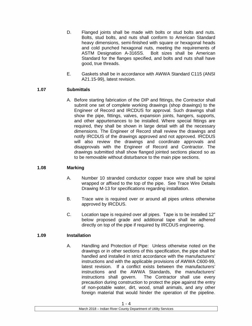
1 - 4 March 2018 – Indian River County Department of Utility Services
D. Flanged joints shall be made with bolts or stud bolts and nuts. Bolts, stud bolts, and nuts shall conform to American Standard heavy dimensions, semi-finished with square or hexagonal heads and cold punched hexagonal nuts, meeting the requirements of ASTM Designation A-316SS. Bolt sizes shall be American Standard for the flanges specified, and bolts and nuts shall have good, true threads.
E. Gaskets shall be in accordance with AWWA Standard C115 (ANSI
A21.15-99), latest revision. 1.07 Submittals
A. Before starting fabrication of the DIP and fittings, the Contractor shall submit one set of complete working drawings (shop drawings) to the Engineer of Record and IRCDUS for approval. Such drawings shall show the pipe, fittings, valves, expansion joints, hangers, supports, and other appurtenances to be installed. Where special fittings are required, they shall be shown in large detail with all the necessary dimensions. The Engineer of Record shall review the drawings and notify IRCDUS of the drawings approved and not approved. IRCDUS will also review the drawings and coordinate approvals and disapprovals with the Engineer of Record and Contractor. The drawings submitted shall show flanged jointed sections placed so as to be removable without disturbance to the main pipe sections.
1.08 Marking
A. Number 10 stranded conductor copper trace wire shall be spiral wrapped or affixed to the top of the pipe. See Trace Wire Details Drawing M-13 for specifications regarding installation.
B. Trace wire is required over or around all pipes unless otherwise
approved by IRCDUS.
C. Location tape is required over all pipes. Tape is to be installed 12” below proposed grade and additional tape shall be adhered directly on top of the pipe if required by IRCDUS engineering.
1.09 Installation
A. Handling and Protection of Pipe: Unless otherwise noted on the drawings or in other sections of this specification, the pipe shall be handled and installed in strict accordance with the manufacturers’ instructions and with the applicable provisions of AWWA C600-99, latest revision. If a conflict exists between the manufacturers’ instructions and the AWWA Standards, the manufacturers’ instructions shall govern. The Contractor shall use every precaution during construction to protect the pipe against the entry of non-potable water, dirt, wood, small animals, and any other foreign material that would hinder the operation of the pipeline.

1 - 5 March 2018 – Indian River County Department of Utility Services
Where the groundwater elevation is above the bottom of the trench, the Contractor shall provide suitable dewatering equipment. All piping shall be placed in a dry trench, unless otherwise approved by IRCDUS.
B. Depth of Cover and Pipe Elevation: Unless otherwise shown on
the drawings, or otherwise approved by IRCDUS, all pipe shall have a minimum cover of 36 inches. Contractor shall determine top of pipe elevation and top of ground elevation for every two joints of pipe installed using a level. Pipe must have the minimum cover described above and must be within +/- 0.2 feet of the top of pipe elevation indicated on the drawings. Installed pipe, which does not meet these requirements, shall be reinstalled until it does meet these requirements. Contractor shall record top of pipe and top of ground elevations and the locations of where these elevations were determined and submit this information to IRCDUS. IRCDUS reserves the right to have Contractor excavate and check top of pipe and top of ground elevations to see if they conform to the aforementioned requirements, at no cost to IRCDUS.
END OF SECTION

Section 2
Water Mains
Polyvinyl Chloride (PVC) Pipe and Fittings

2 - 1 March 2018 – Indian River County Department of Utility Services
Section 2
Water Mains Polyvinyl Chloride Pipe (PVC) and Fittings
2.01 General
A. PVC pipe shall be allowed for use as potable water pipe where compatible with the specific conditions of the project. IRCDUS may require the use of material other than PVC during construction permit review or by IRCDUS field personnel during construction, if it is determined that PVC pipe is unsuitable for the particular application.
B. The pipe shall be identified by its nominal pipe size, plastic pipe
material code, SDR class, pressure rating, ASTM Designation, manufacturers’ name, production code, and the National Sanitation Foundation seal for potable water (NSF-pw).
2.02 Pipe for Sizes 3 Inches in Diameter and Smaller
A. All pipe intended for conveying or transmitting potable water shall be designed for a minimum working pressure of 350 psi.
B. PVC pipe shall conform to the ASTM 2241, latest revision. Pipe
shall be SDR 21 with a pressure rating of 200 psi. Joint design tested to the requirements of ASTM D 3139. Rubber rings shall conform to ASTM F 477 and D 1869. Pipe to be made to exceed the requirements of the material section of ASTM D 2241.
C. PVC pipe shall be in accordance with IRCDUS Approved
Manufacturers’ Products List or equal.
D. The pipe shall be “blue” in color.
E. No solvent weld joints are permitted.
2.03 Pipe for Sizes 4 Inches Through 12 Inch in Diameter
A. All pipe intended for conveying or transmitting potable water shall be designed for a minimum working pressure of 350 psi.
B. PVC pipe shall conform to AWWA Standard Specifications C900-
97, or latest revision, or C909-98, or latest revision and ASTM D1784 and D2241, latest revision. PVC pressure pipe shall be made from Class 12454-A or Class 12454-B material and conform

2 - 2 March 2018 – Indian River County Department of Utility Services
to the outside diameter of cast iron pipe with a minimum wall thickness of DR18.
C. PVC pipe shall be in accordance with IRCDUS Approved
Manufacturers’ Products List or equal. D. The pipe shall be “blue” in color.
E. The pipe shall be identified by its nominal pipe size, plastic pipe
material code, DR class, pressure rating, ASTM Designation, manufacturers’ name, code, and the National Sanitation Foundation seal for potable water (NSF-pw).
2.04 Pipe for Sizes 14 Inches through 36 Inches in Diameter
A. All pipe intended for conveying or transmitting potable water shall
be designed for a minimum working pressure of 350 psi. B. PVC pipe shall conform to AWWA Standard Specifications C900-
97 and ASTM D1784, or latest revisions. PVC pressure pipe shall be made from Class 12454-A or Class 12454-B material and conform to the outside diameter of cast iron pipe with a minimum wall thickness of DR18.
C. PVC pipe shall be in accordance with IRCDUS Approved
Manufacturers’ Products List or equal. D. The pipe shall be “blue” in color.
E. The pipe shall be identified by its nominal pipe size, plastic pipe
material code, DR class, pressure rating, ASTM Designation, manufacturers’ name, code, and the National Sanitation Foundation seal for potable water (NSF-pw).
2.05 Joints
A. Joints for PVC pipe shall be bell and spigot push-on rubber gasket type only unless otherwise approved by IRCDUS. No solvent weld or threaded joints will be permitted.
B. Restraining joints, when required, shall be in accordance with
IRCDUS Approved Manufacturers’ Products List or equal. 2.06 Fittings
A. All fittings shall be ductile iron mechanical joint and shall conform to AWWA Standard Specifications C110/A21.10-98 or C153/A 21.53-00, or latest revisions. Fittings shall be cement mortar lined and seal-coated in accordance with AWWA Standard Specifications C104/A21.4-95, or latest revision.

2 - 3 March 2018 – Indian River County Department of Utility Services
B. The pressure rating shall be 350 psi (Class 350).
C. Joint restraint, when required, shall be in accordance with IRCDUS Approved Manufacturers’ Products List or equal.
2.07 Submittals
A. Before starting installation of the PVC pipe and fittings, the Contractor shall submit one set of complete working drawings (shop drawings) to the Engineer of Record and IRCDUS for approval. Such drawings shall show the pipe, fittings, valves, hydrants, blow-offs, services, and other appurtenances to be installed. Where special fittings are required, they shall be shown in large detail with all the necessary dimensions. The Engineer of Record shall review the drawings and notify IRCDUS of the drawings approved and not approved. IRCDUS shall also review the drawings and coordinate approvals and disapprovals with the Engineer of Record and Contractor.
2.08 Marking
A. Number 10 stranded conductor copper trace wire shall be spiral wrapped or affixed to the top of the pipe. See Trace Wire Details Drawing M-13 for specifications regarding installation.
B. Trace wire is required over or around all pipes.
C. Location tape is required over all pipes. Tape is to be installed 12”
below proposed grade and additional tape shall be adhered directly on top of the pipe if required by IRCDUS engineering.
2.09 Storage
A. PVC pipes are not to be stored where exposed to direct sunlight because of possible ultraviolet light degradation. Pipes stored on the jobsite are to be covered. PVC pipes that exhibit discoloration or fading from their original color will be rejected by IRCDUS field representatives.
2.10 Installation
A. Handling and Protection of Pipe: Unless otherwise noted on the drawings or in other sections of these standards, the pipe shall be handled and installed in strict accordance with the manufacturers’ instructions and with the applicable provisions of AWWA Standard Specifications C605-94, or latest revision. If a conflict exists between the manufacturers’ instructions and the AWWA Standard Specifications, the manufacturers’ instructions shall govern. The Contractor shall use every precaution during construction to protect the pipe against the entry of non-potable water, dirt, wood, small animals, and any other foreign material that would hinder the operation of the pipeline. Where the groundwater elevation is

2 - 4 March 2018 – Indian River County Department of Utility Services
above the bottom of the trench, the Contractor shall provide suitable dewatering equipment. All piping shall be placed in a dry trench, unless approved by IRCDUS.
B. Depth of Cover and Pipe Elevation: Unless otherwise shown on
the drawings, or otherwise authorized by IRCDUS, all pipe shall have a minimum depth of cover of 36 inches. Contractor shall determine top of pipe elevation and top of finished grade elevation for every two joints of pipe installed using a level. Pipe must have the minimum cover described above and must be within +/- 0.2 feet of the top of pipe elevation indicated on the drawings. Installed pipe, which does not meet these requirements, shall be reinstalled until it does meet these requirements. Contractor shall record top of pipe and top of ground elevations and the locations of where these elevations were determined and submit this information to Engineer or his representative. IRCDUS reserves the right to have Contractor excavate and check top of pipe and top of ground elevations to see if they conform to the aforementioned requirements.
END OF SECTION

Section 3
Water Services - Crosslinked Polyethylene (PEXa) Tubing and
Water Mains - High Density Polyethylene Pipe (HDPE)
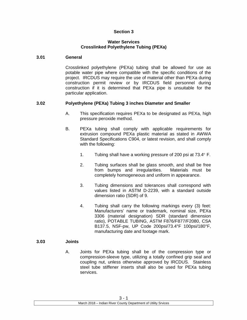
3 - 1 March 2018 – Indian River County Department of Utility Srvices
Section 3
Water Services Crosslinked Polyethylene Tubing (PEXa)
3.01 General
Crosslinked polyethylene (PEXa) tubing shall be allowed for use as potable water pipe where compatible with the specific conditions of the project. IRCDUS may require the use of material other than PEXa during construction permit review or by IRCDUS field personnel during construction if it is determined that PEXa pipe is unsuitable for the particular application.
3.02 Polyethylene (PEXa) Tubing 3 inches Diameter and Smaller
A. This specification requires PEXa to be designated as PEXa, high pressure peroxide method.
B. PEXa tubing shall comply with applicable requirements for extrusion compound PEXa plastic material as stated in AWWA Standard Specifications C904, or latest revision, and shall comply with the following:
1. Tubing shall have a working pressure of 200 psi at 73.4° F. 2. Tubing surfaces shall be glass smooth, and shall be free
from bumps and irregularities. Materials must be completely homogeneous and uniform in appearance.
3. Tubing dimensions and tolerances shall correspond with
values listed in ASTM D-2239, with a standard outside dimension ratio (SDR) of 9.
4. Tubing shall carry the following markings every (3) feet:
Manufacturers’ name or trademark, nominal size, PEXa 3306 (material designation) SDR (standard dimension ratio), POTABLE TUBING, ASTM F876/F877/F2080, CSA B137.5, NSF-pw, UP Code 200psi/73.4°F 100psi/180°F, manufacturing date and footage mark.
3.03 Joints
A. Joints for PEXa tubing shall be of the compression type or compression-sleeve type, utilizing a totally confined grip seal and coupling nut, unless otherwise approved by IRCDUS. Stainless steel tube stiffener inserts shall also be used for PEXa tubing services.

3 - 2 March 2018 – Indian River County Department of Utility Srvices
3.04 Installation
A. Backfill shall be free of rocks and debris. B. Bending radius shall be large enough so that tubing is not crimped
or damaged and so that the flow of water is not restricted. Manufacturers’ minimum radius recommendations are to be utilized during installation of PEXa tubing.
C. PEXa tubing shall have ability for kink repair using a heat gun.
3.05 Marking
A. Number 10 stranded conductor copper trace wire shall be spiral wrapped or affixed to the top of the pipe. See Trace Wire Details M-13 for specifications regarding installation.
B. Trace wire is required over or around all pipes.
C. Location tape is required over all pipes. Tape is to be installed 12”
below proposed grade and additional tape adhered directly on top of the pipe if required by IRCDUS engineering.
3.06 Pressure PEXa Pipe
A. PEXa pipe shall be allowed for use as all pressure utility pipes where compatible with the specific conditions of the project. The use of material other than PEXa pipe may be required by IRCDUS during construction permit review or by IRCDUS field personnel, if it is determined that PEXa is unsuitable for the particular application.
B. Documentation from the resin’s manufacturer showing results of
the following tests for resin identification:
1. Melt Flow Index ASTM D 1238 2. Density ASTM F876
C. All PEXa pipe and fittings shall be from a single manufacturer on
the Approved Manufacturers’ Product List. The pipe shall be designed, constructed and installed in accordance with the best practices and methods and shall comply with these Specifications. See Approved Manufacturers’ Product List.
D. Finished Product Evaluation
1. Production staff for the items listed below shall check each
length of pipe produced. The results of all measurements shall be recorded on production sheets that become part of the manufacturers’ permanent records.

3 - 3 March 2018 – Indian River County Department of Utility Srvices
a. Pipe in process shall be checked visually, inside and out for cosmetic defects (grooves, pits, hollows, etc.)
b. Pipe outside diameter shall be measured using a suitable periphery tape to ensure conformance with ASTM F714 or ASTM D-3035 whichever is applicable.
c. Pipe wall thickness shall be measured at 12 equally spaced locations around the circumference at both ends of the pipe to ensure conformance with ASTM F714 or ASTM D-3035, whichever is applicable.
d. Pipe length shall be measured. e. Pipe marking shall be examined and checked for
accuracy. f. Pipe ends shall be checked to ensure they are cut
square and clean. g. Subject inside surface to a “reverse bend test” to
ensure the pipe is free of oxidation (brittleness).
E. Stress Regression Testing 1. The PEXa pipe manufacturer shall provide certification that
stress regression testing has been performed on the specific PEXa resin being utilized in the manufacturing of this product. This stress regression testing shall have been done in accordance with ASTM D2837 and the manufacturer shall provide a product supplying a minimum Hydrostatic Design Basis (HDB) of 1,600 psi as determined in accordance with ASTM D2837.
F. Developer is responsible for compatibility between pipe materials,
fittings and appurtenances. G. The pipe manufacturer shall provide a warranty against
manufacturing defects of material and workmanship for a period of ten (10) years after the final acceptance of the project by the IRCDUS. The manufacturer shall replace at no expense to IRCDUS any defective pipe material including labor within the warranty period.
3.07 Materials for High Density Polyethylene Pipe (HDPE) Sizes 3 inch in
Diameter and Smaller
A. Materials used for the manufacture of HDPE pipe and fittings shall be made from a PE 3408 PE resin compound meeting cell classification 334434D per ASTM D3350; and meeting Type III, Class C, Category 5, Grade P34 per ASTM D1248
B. HDPE pipe shall comply with AWWA Standard Specifications
C906-99 or latest revision.

3 - 4 March 2018 – Indian River County Department of Utility Srvices
C. If rework compounds are required, only those generated in the manufacturers’ own plant from resin compounds of the same class and type from the same raw material supplier shall be used.
D. Dimensions and workmanship shall be as specified by ASTM
F714. HDPE fittings and transitions shall meet ASTM D3261. HDPE pipe shall have a minimum density of 0.955 grams per cubic centimeter. All HDPE pipe and fittings shall have a Hydrostatic Design Basis (HDB) of 1,600 psi.
E. HDPE pipe and accessories 4” and greater in diameter, shall be
160 psi at 73.4° F meeting the requirements of Standard Dimension Ratio (SDR) 11 as minimum strength.
F. The pipe manufacturer must certify compliance, with the above
requirements. G. HDPE flange adapters at pipe material transitions shall be backed
up by stainless steel flanges conforming to ANSI B16.1 and shaped as necessary to suit the outside dimensions of the pipe. The flange adapter assemblies shall be connected with corrosion resisting bolts and nuts of Type 316 Stainless Steel as specified in ASTM A726 and ASTM A307. All bolts shall be tightened to the manufacturers’ specified torques. Bolts shall be tightened alternatively and evenly.
3.08 Materials for High Density Polyethylene Pipe (HDPE) Sizes 4 inches in Diameter and Larger
A. Materials used for the manufacture of HDPE pipe and fittings shall
be made from a PE 3408 resin compound meeting cell classification 345434C per ASTM D3350; and meeting Type 111, Class C, Category 5, Grade P34 per ASTM D1248.
B. HDPE pipe shall comply with AWWA Standard Specifications
C901-96 or latest revision.
C. If rework compounds are required, only those generated in the manufacturers’ own plant from resin compounds of the same class and type from the same raw material supplier shall be used.
D. Dimensions and workmanship shall be as specified by ASTM D-
3035. HDPE fittings and transitions shall meet ASTM D3261. PE pipe shall have a minimum density of 0.955 grams per cubic centimeter. All HDPE pipe and fittings shall have a Hydrostatic Design Basis (HDB) of 1,600 psi.
E. HDPE pipe and accessories 3” and smaller in diameter, shall be
160 psi at 73.4° F meeting the requirements of Standard Dimension Ratio (SDR) 9 as minimum strength.
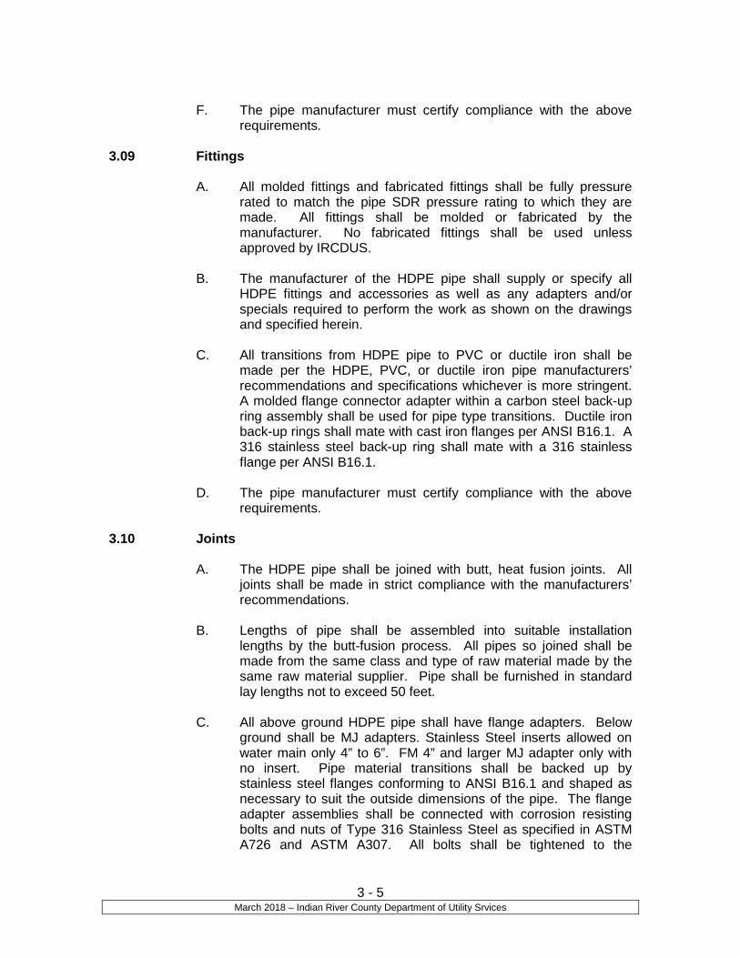
3 - 5 March 2018 – Indian River County Department of Utility Srvices
F. The pipe manufacturer must certify compliance with the above
requirements.
3.09 Fittings
A. All molded fittings and fabricated fittings shall be fully pressure rated to match the pipe SDR pressure rating to which they are made. All fittings shall be molded or fabricated by the manufacturer. No fabricated fittings shall be used unless approved by IRCDUS.
B. The manufacturer of the HDPE pipe shall supply or specify all
HDPE fittings and accessories as well as any adapters and/or specials required to perform the work as shown on the drawings and specified herein.
C. All transitions from HDPE pipe to PVC or ductile iron shall be
made per the HDPE, PVC, or ductile iron pipe manufacturers’ recommendations and specifications whichever is more stringent. A molded flange connector adapter within a carbon steel back-up ring assembly shall be used for pipe type transitions. Ductile iron back-up rings shall mate with cast iron flanges per ANSI B16.1. A 316 stainless steel back-up ring shall mate with a 316 stainless flange per ANSI B16.1.
D. The pipe manufacturer must certify compliance with the above
requirements.
3.10 Joints
A. The HDPE pipe shall be joined with butt, heat fusion joints. All joints shall be made in strict compliance with the manufacturers’ recommendations.
B. Lengths of pipe shall be assembled into suitable installation
lengths by the butt-fusion process. All pipes so joined shall be made from the same class and type of raw material made by the same raw material supplier. Pipe shall be furnished in standard lay lengths not to exceed 50 feet.
C. All above ground HDPE pipe shall have flange adapters. Below ground shall be MJ adapters. Stainless Steel inserts allowed on water main only 4” to 6”. FM 4” and larger MJ adapter only with no insert. Pipe material transitions shall be backed up by stainless steel flanges conforming to ANSI B16.1 and shaped as necessary to suit the outside dimensions of the pipe. The flange adapter assemblies shall be connected with corrosion resisting bolts and nuts of Type 316 Stainless Steel as specified in ASTM A726 and ASTM A307. All bolts shall be tightened to the

3 - 6 March 2018 – Indian River County Department of Utility Srvices
manufacturers’ specified torques. Bolts shall be tightened alternatively and evenly.
3.11 Pipe Identification
A. The following shall be continuously indent printed on the pipe or spaced at intervals not exceeding 5-ft. 1. Name and/or trademark of the pipe manufacturer. 2. Nominal pipe size. 3. Dimension ratio. 4. The letters PE followed by the polyethylene grade in
accordance with ASTM D1248, followed by the hydrostatic design basis in 160’s of psi, e.g., PE 3408.
5. Manufacturing standard reference, e.g., ASTM F714 or D-3035, as required.
6. A production code from which the date and place of manufacture can be determined.
7. HDPE pipe used for potable water will have a “blue” stripe and reclaim water will have a “purple” stripe, continuous along the entire length of pipe.
B. Number 10 stranded conductor copper trace wire shall be spiral
wrapped or affixed to the top of all pipe and fittings. See Trace Wire Details Drawing M-13 for specifications regarding installation.
3.12 Installation by Open Cut Method
A. HDPE Pipe shall be installed in accordance with the instruction of the manufacturer, as shown on the Drawings and as specified herein. A factory qualified joining technician as designated by the pipe manufacturer shall do all heat fusion joints.
B. Care shall be taken in loading, transporting and unloading to
prevent injury to the pipe. Pipe or fittings shall not be dropped. All pipe or fittings shall be examined before installation, and no piece shall be installed which is found to be defective. Any damage to the pipe shall be repaired as directed by the Engineer of Record and IRCDUS. If any defective pipe is discovered after it has been installed, it shall be removed and replaced with a sound pipe in a satisfactory manner by the Contractor, at his own expense.
C. Under no circumstances shall the pipe or accessories be dropped
into the trench.
D. Care shall be taken during transportation of the pipe such that it will not be cut, kinked, or otherwise damaged.
E. Ropes, fabric, or rubber protected slings and straps shall be used
when handling pipes. Chains, cables, or hooks inserted into the
3 - 7 March 2018 – Indian River County Department of Utility Srvices
pipe ends shall not be used. Two slings spread apart shall be used for lifting each length of pipe.
F. Pipes shall be stored on level ground, preferably turf or sand, free
of sharp objects, which could damage the pipe. Stacking of the PE pipe shall be limited to a height that will not cause excessive deformation of the bottom layers of pipes under anticipated temperature conditions. Where necessary due to ground conditions, the pipe shall be stored on wooden sleepers, spaced suitably and of such width as not to allow deformation of the pipe at the point of contact with the sleeper or between supports.
G. Care shall be exercised when lowering pipe into the trench to
prevent damage or twisting of the pipe.
H. Pipe shall be laid to lines and grade shown on the Drawings with bedding and backfill as shown on the Drawings.
I. When installation of pipe is not in progress, including lunchtime,
the open ends of the pipe shall be closed by fabricated plugs, or by other approved means.
J. Pipe shall be stored on clean level ground to prevent undue
scratching or gouging. The handling of the pipe shall be in such a manner that the pipe is not damaged by dragging it over sharp and cutting objects. The maximum allowable depth of cuts, scratches or gouges on the exterior of the pipe is 5 percent of wall thickness. Sections of pipe with cuts, scratches or gouges exceeding five percent of the pipe wall thickness shall be removed completely and the ends of the pipeline rejoined. The interior pipe surface shall be free of cuts, gouges or scratches.
K. HDPE pipe shall be joined by the method of thermal butt fusion,
as outlined in ASTM D2657. All joints shall be made in strict compliance with the manufacturers’ recommendations.
L. Mechanical connections of the HDPE pipe to auxiliary equipment
such as valves, pumps and tanks shall be through flanged connections which shall consist of the following:
1. An HDPE flange shall be thermally butt-fused to the stub
end of the pipe. A stainless steel or ductile iron back-up ring shall be used on both sides of the connection prior to thermally butt-fusing the PE flange.
2. A 316 stainless steel back-up ring shall mate with a 316 stainless steel flange.
3. Ductile iron back-up rings shall mate with cast iron flanges.
M. Flange connections shall be provided with a full-face neoprene gasket.
3 - 8 March 2018 – Indian River County Department of Utility Srvices
N. All HDPE pipe must be at the temperature of the surrounding soil at the time of backfilling and compaction.
O. No single piece of pipe shall be laid unless it is straight. The
centerline of the pipe shall not deviate from a straight line drawn between the centers of the openings at the ends of the pipe by more than 1/16-in per foot of length. If a piece of pipe fails to meet this requirement check for straightness, it shall be rejected and removed from the site. Laying instructions of the manufacturer shall be explicitly followed.
P. If a defective pipe is discovered after it has been installed, it shall
be removed and replaced with a sound pipe in a satisfactory manner. All pipe and fittings shall be thoroughly cleaned before installation, shall be kept clean until they are used in the work and when laid, shall conform to the lines and grades required.
Q. As soon as the excavation is complete to normal grade of the
bottom of the trench, bedding shall be placed, compacted and graded to provide firm, uniform and continuous support for the pipe. Bell holes shall be excavated so that only the barrel of the pipe bears upon the bedding. The pipe shall be laid accurately to the lines and grades indicated on the Construction Plans. Blocking under the pipe will not be permitted. Bedding shall be placed evenly on each side of the pipe to mid-diameter and hand tools shall be used to force the bedding under the haunches of the pipe and into the bell holes to give firm continuous support for the pipe. Bedding shall then be placed to 12-in above the top of the pipe. The initial 3 feet of backfill above the bedding shall be placed in 1 foot layers and carefully compacted. Generally the compaction shall be done evenly on each side of the pipe and compaction equipment shall not be operated directly over the pipe until sufficient backfill has been placed to ensure that such compaction equipment will not have a damaging effect on the pipe. The pipe manufacturers’ representative prior to use shall approve equipment used in compacting the initial 3 feet of backfill. Pipe shall be installed per IRCDUS Drawing M-1 or M-2, Trench Details.
R. Good alignment shall be preserved during installation. The
deflection at joints shall not exceed that recommended by manufacturer. Fittings, in addition to those shown on the Drawings, shall be provided, if required, in crossing of utilities that may be encountered upon opening the trench.
S. Each length of the pipe shall have the assembly mark aligned with
the pipe previously laid and held securely until enough backfill has cramped.
T. Before any joint is made, the pipe shall be checked to assure that
a close joint with the next adjoining pipe has been maintained and

3 - 9 March 2018 – Indian River County Department of Utility Srvices
that the inverts are matched and conform to the required grade. The pipe shall not be driven down to grade by striking it.
U. Precautions shall be taken to prevent flotation of the pipe in the
trench.
V. When moveable trench bracing such as trench boxes, moveable sheeting, shoring or plates are used to support the sides of the trench, care shall be used in placing and moving the boxes or supporting bracing to prevent movement of the pipe, or disturbance of the pipe bedding and the backfill. Trench boxes, moveable sheeting, shoring or plates shall not be allowed to extend below the top of the pipe. As trench boxes, moveable sheeting, shoring or plates are moved, pipe bedding shall be placed to fill any voids created and the backfill shall again be compacted to provide uniform side support for the pipe.
W. Sheeting and shoring will be required as determined in the field in
accordance with OSHA regulations.
X. Restrained joints shall be installed where shown on the Construction Plans, as required by IRCDUS Standards, or otherwise as directed by IRCDUS.
3.13 Marking
A. Number 10 stranded conductor copper trace wire shall be spiral wrapped or affixed to the top of the pipe. See Trace Wire Details, M-13 for specifications regarding installation.
B. Trace wire is required over or around all pipes.
C. Location tape is required over all pipes. Tape is to be installed 12” below proposed grade and additional tape shall be adhered directly on top of the pipe if required by IRCDUS.
3.14 Trenchless Installation of High Density Polyethylene (HDPE)
Pressure Mains by Directional Bore
A. Description
1. Portions of the pressure mains shall be installed by the directional bore method within the limits indicated of the contract plans and as specified here in. Generally, as a minimum, the pressure main is to be located within the road right-of-way and shall be installed by directional boring.
2. This section includes material, performance and installation standards, and the contractor’s responsibilities associated with the furnishing of labor, material, equipment, and identical required to install, complete, required trenchless installation of
3 - 10 March 2018 – Indian River County Department of Utility Srvices
pressure mains, as shown on the Drawings and as specified herein.
B. Experience
1. The Contractor must demonstrate expertise in trenchless method by providing a list of ten utility references for which similar work has been performed in the last two years. The references should include a name and phone number where the contact can be made to verify the Contractor’s capability. The Contractor must provide documentation showing successful completion of the projects used for reference. Conventional trenching experience will not be considered applicable.
2. Supervisory personnel must be adequately trained and shall have at least four years of experience in directional boring. The Contractor shall submit the names and resumes of all supervisory field personnel prior to construction.
3. Directional boring equipment shall be capable of installing the minimum pipe diameter noted on the drawings.
C. Submittals
1. Submit technical data for equipment including clay slurry material, method of installation with working drawings, and proposed sequence of construction for approval by the IRCDUS.
2. Prior to approval for directional boring, the Contractor must submit the names of supervisory personnel, and history information of the directional boring experience. In addition, the Contractor must submit for approval the nameplate, data for the drilling equipment, mobile spoils removal units and Material Safety Data Sheets (MSDS) for the drilling slurry compounds.
3. The Contractor is required to bring to the attention of the
engineer any known design discrepancies with actual tunneling methods that the contractor will be performing. This shall be stated in writing to the Engineer at the pre-construction meeting.
D. Installation
1. Installation shall be in a trenchless manner producing continuous bores.
2. The tunneling system shall be remotely steerable and permit electronic monitoring of tunnel depth and location. Accurate

3 - 11 March 2018 – Indian River County Department of Utility Srvices
placement of pipe within a +/- 2-inch window is required both horizontally and vertically. Turning capability of 90-degrees radius in 40 feet is required. Continuous monitoring of the boring head is required, including across open water if necessary.
3. The directional boring Contractor shall submit certification, by a Professional Engineer licensed in the State of Florida, that the directional boring has been performed in accordance to the construction drawings, and shall submit signed and sealed drawings. AS-Built Record Drawings shall be provided both in electronic format and hard paper copy.
4. Tunneling shall be performed by a fluid-cutting process (high pressure-low volume) utilizing liquid clay i.e. bentonite. The clay lining will maintain tunnel stability and provide lubrication in order to reduce frictional drag while the pipe is being installed. In addition, the clay fluid must be totally inert and contain no environmental risk. The Contractor must also have a mobile vacuum spoils recovery vehicle on site to remove the drilling spoils from the access pits. The spoils must then be transported from the job site and be properly disposed off the site. The drilling spoils shall not, under any circumstances, be disposed into a sanitary sewer, storm, or other public or private drainage system. Spoils may be transported to the County’s Solid Waste Facility and the cost of disposal shall be at the Contractor’s expense.
5. Liquid clay type colloidal drilling fluid shall consist of at least 10 percent of high-grade carefully processed bentonite to consolidate cuttings of the soil, to seal the walls of the hole, and to furnish lubrication for subsequent removal of cuttings. The slurry that is heavier than the surrounding material, is high in colloids of the bentonite type and it will deposit a thin filter cake of low permeability material on the walls of the bore. This will allow only a small amount of the fluid to pass into the surrounding soils and will stabilize the bore. The colloidal content of the fluid imparts excellent lubricating qualities to the slurry that is a distinct aid to the removal of the soil cuttings.
6. Pneumatic or water-jetting methods will be considered unacceptable due to the possibility of surface subsidence.
7. After an initial bore has been completed, a reamer will be installed at the termination pit and the pipe shall be pulled back to the starting pit. The reamer shall be capable of discharging liquid clay to facilitate the installation of the pipe into a stabilized and lubricated tunnel.

3 - 12 March 2018 – Indian River County Department of Utility Srvices
8. A minimum of two insulated #6 stranded conductor copper tracer wire shall be wrapped or affixed to the top of the pipe and fittings along with the HDPE pipe. The tracer wire shall be tested for continuity or traceability upon completed installation. Should both tracer wires fail to test for continuity then the test shall be considered a failure and the wires shall be replaced.
9. Upon completion of boring and pipe installation, the Contractor shall remove all spoils from the starting and termination pits. All pits shall be restored to their original condition.
10. Restoration shall be as required by IRCDUS. The shoulders, ditches, banks, and slopes of roads and railroads crossed and paralleled shall not wash out before becoming accepted.
END OF SECTION

Section 4
Gravity Sanitary Sewers Ductile Iron Pipe (DIP) and Fittings
4 - 1 March 2018 – Indian River County Department of Utility Services
Section 4
Gravity Sanitary Sewers Ductile Iron Pipe (DIP) and Fittings
4.01 General
A. DIP shall be allowed for use as gravity sewer pipe where compatible with the specific conditions of the project. IRCDUS may require the use of material other than ductile iron during construction permit review or by IRCDUS field personnel during construction, if it is determined that DIP is unsuitable for the particular application.
B. All DIP shall be manufactured in accordance with AWWA
Standard Specifications C150/A21.50-96 and C151/A21.51-96, or latest revisions, and shall be pressure Class 300 or 350 minimum, as depicted on Table 4.1 on page 4-2. All DIP crossings under roadways and other traffic areas shall be pressure Class 350 minimum.
C. Unless specifically indicated otherwise, restrained push-on joint
underground piping shall be manufactured restrained bell and spigot and above ground piping shall be flanged.
D. Cutting of DIP shall be by sawing only.
4.02 Pipe
A. DIP shall be bell and spigot cast in accordance with the latest AWWA Standard Specifications C150/A21.50-96 and C151/A21.51-96. Cast ductile iron shall have a minimum tensile strength of 60,000 psi with a minimum yield strength of 42,000 psi. Pipe wall thicknesses shall be computed in accordance with AWWA Standard Specifications C150/A21.50-96, latest revision, using the physical characteristics cited above with a minimum working pressure of 200 psi and a Laying Condition “Type 2”. Unless otherwise indicated or specified herein, the pipe shall have the minimum wall thickness according to class designation for diameters shown. All pipes shall be given a minimum factory hydrostatic test of 500 psi.

4 - 2 March 2018 – Indian River County Department of Utility Services
Table 4.1 Pressure Class 300 and 350
4.03 Fittings
A. All underground fittings shall be either push-on, restrained, or mechanical joint. Mechanical joints shall conform to AWWA Standard Specifications C110/A21.10-98 or C153/A21.53-00, or latest revisions. All aboveground fittings shall be flanged joint.
B. The pressure rating shall be 350 psi (Class 350 Pipe).
C. All fittings shall be lined with the same materials as specified for
the pipe, as per paragraph 4.04.
D. Joint restraints, when required, shall be in accordance with IRCDUS Approved Manufacturers’ Products List or an approved equal.
4.04 Lining and Coating
A. Unless otherwise indicated, all DIP shall be factory lined and coated.
B. For 4” and larger, the interior of the pipe shall have a fusion-
bonded ceramic epoxy lining. The epoxy material shall be applied in 1 coat with a minimum dry film thickness of 40.0 mils and shall be per the Approved Manufacturers’ Products List. If and where directed by the Engineer of Record and the IRCDUS, a polyethylene encasement shall be provided over pipe and fittings.
Nominal Size
Diameter (Inches)
Actual Outside Diameter (Inches)
300 PSI Wall
Thickness (Inches)
350 PSI Wall
Thickness (Inches)
3 3.96 --- 0.25 4 4.80 --- 0.25 6 6.90 --- 0.25 8 9.05 --- 0.25
10 11.10 --- 0.26 12 13.20 --- 0.28 14 15.30 0.30 0.31 16 17.40 0.32 0.34 18 19.50 0.34 0.36 20 21.60 0.36 0.38 24 25.80 0.40 0.43 30 32.00 0.45 0.49 36 38.30 0.51 0.56 42 44.50 0.52 0.63 48 50.80 0.64 0.70 54 57.56 0.72 0.79 60 61.61 0.76 0.83 64 65.67 0.80 0.87

4 - 3 March 2018 – Indian River County Department of Utility Services
C. Unless otherwise specified, the exterior of the pipe shall have a
bituminous coating to a minimum dry film thickness of 1.0 mil. See Approved Manufacturers’ Products List for coating material.
D. Lining Inspection:
1. All DIP and fitting linings shall be checked for thickness using a magnetic film thickness gauge. The thickness testing shall be done using the method outlined SSPC-PA-2 film thickness rating.
2. The interior lining of all pipe and fittings shall be tested for pinholes with a nondestructive 2,500-volt test.
3. Each pipe joint and fitting shall be marked with the date of application of the lining system and with its numerical sequence of application on that date.
E. The pipe or fitting manufacturer must supply a certificate attesting
to the fact that the applicator met the requirements of this specification, and that the material used was as specified, and that the material was applied as required by the specification.
F. Anywhere that the coating is removed purposely or accidentally,
the area shall be cleaned of any rust, grease, and dirt and re-coated to a minimum dry film as specified for the individual piece.
G. If and when directed by the Engineer of Record and IRCDUS, a
polyethylene encasement shall be provided around pipe, fittings, and valves. The material, installation, and workmanship shall conform to applicable sections of AWWA Standard Specifications C105/A21.5-99, or latest revision. Installation methods A or B shall be employed using flat tube polyethylene. The Contractor shall make provisions to keep the polyethylene from direct exposure to sunlight prior to installation. Backfilling following installation shall be completed without delay to avoid exposure to sunlight.
H. All exposed sewer DIP shall be coated (painted) green per the
Approved Manufacturers’ Product List. 4.05 Bell and Spigot Connections
A. Unless specifically indicated otherwise, restrained push-on joint underground piping shall be manufactured restrained bell and spigot and above ground piping shall be flanged in accordance with AWWA Standard Specifications C111/A21.11-00, or latest revision. Pipe restraints shall also be in accordance with IRCDUS Standards or as directed by Engineer or IRCDUS.

4 - 4 March 2018 – Indian River County Department of Utility Services
4.06 Submittals
A. Before starting fabrication of the DIP and fittings, the Contractor shall submit one set of complete detailed working drawings (shop drawings) to the Engineer of Record and IRCDUS for approval. Such drawings shall show the pipe, fittings, valves, expansion joints, hangers, supports, and other appurtenances to be installed. Where special fittings are required, they shall be shown in large detail with all the necessary dimensions. The Engineer of Record shall review the drawings and notify IRCDUS of the drawings approved and not approved. IRCDUS shall also review the drawings and coordinate approvals and disapprovals with the Engineer of Record and Contractor. The drawings submitted shall show flanged jointed sections placed so as to be removable without disturbance to the main pipe sections.
4.07 Marking
A. Number 10 stranded conductor copper trace wire shall be spiral
wrapped or affixed to the top of the pipe. See Trace Wire Details Drawing M-13 for specifications regarding installation.
B. Trace Wire is required over or around all pipes.
C. Location tape is required over all pipes. Tape is to be installed 12”
below proposed finished grade and additional tape shall be adhered directly on top of the pipe if required by IRCDUS.
4.08 Installation
A. Handling and Protection of Pipe: Unless otherwise noted on the drawings or in other sections of these standards, the pipe shall be handled and installed in strict accordance with the manufacturers’ instructions. The Contractor shall use every precaution during construction to protect the pipe against the entry of non-potable water, dirt, wood, small animals, and any other foreign material that would hinder the operation of the pipeline. Where the groundwater elevation is above the bottom of the trench, the Contractor shall provide suitable dewatering. All piping shall be placed in a dry trench, unless IRCDUS approves wet trench installation.
B. Depth of Cover and Pipe Elevation: Unless otherwise shown on the
drawings, or otherwise authorized by IRCDUS, all pipe shall have a minimum cover of 36 inches. Contractor shall determine top of pipe elevation and top of ground elevation for every two joints of pipe installed using a level. Pipe must have the minimum cover described above and must be within +/- 0.2 feet of the top of pipe elevation indicated on the drawings. Installed pipe, which does not meet these requirements, shall be reinstalled until it does meet these requirements. Contractor shall record top of pipe and top of ground elevations and the locations of where these elevations were

4 - 5 March 2018 – Indian River County Department of Utility Services
determined and submit this information to IRCDUS. IRCDUS reserves the right to have Contractor excavate and check top of pipe and top of ground elevations to see if they conform to the aforementioned requirements, at no cost to IRCDUS.
END OF SECTION

Section 5
Gravity Sanitary Sewers Polyvinyl Chloride (PVC) Pipe and Fittings
5 - 1 March 2018 – Indian River County Department of Utility Services
Section 5
Gravity Sanitary Sewers Polyvinyl Chloride (PVC) Pipe and Fittings
5.01 General
A. PVC pipe shall be allowed for use as gravity sewer pipe where compatible with the specific conditions of the project. IRCDUS may require the use of material other than PVC during construction permit review or by IRCDUS field personnel during construction, if it is determined that PVC pipe is unsuitable for the particular application.
B. PVC gravity sewer pipe can be used up to a depth of sixteen feet
as specified herein. All pipe used for depths greater than 16 feet, shall be approved by IRCDUS.
5.02 Pipe and Fittings
A. Gravity sewer mains and laterals shall be extra strength PVC pipe and shall conform to the latest ASTM Designation D3034-SDR26. Fittings installed in PVC pipe shall conform to the same specifications as the pipe in which they are installed.
B. In addition to the requirements of ASTM specifications, the pipe
shall not be out-of-round or crooked in alignment as determined by the Engineer of Record and/or IRCDUS. Any length of pipe 6 inches or greater in diameter whose inside diameters measured at right angles to each other vary more than ¼ inch may be rejected.
C. PVC pipe shall be a maximum of 20 feet in length and shall be in
accordance with IRCDUS Approved Manufacturers’ Products List.
D. Material shall meet or exceed the requirements of ASTM Designation 1784, Type 1, Grade 1 (12454-B). All P.V.C. materials shall be stored in accordance with the manufacturers’ specifications (not in direct sunlight). PVC pipe and fittings, which show signs of ultraviolet degradation, are considered substandard and unfit for use, and will be rejected by the IRCDUS’s Engineer.
E. All wyes, fittings, laterals, and manhole couplings shall be
manufactured by same manufacturing company as the pipe or approved equal, see Approved Manufacturers’ Product List. Adapters shall be compatible to the approved pipe and appurtenances. All joints shall be rubber gasketed.
F. The pipe shall be “green” in color.
5 - 2 March 2018 – Indian River County Department of Utility Services
5.03 Pipe Joint Seals
A. Joint seals in PVC pipe and fittings shall comply with ASTM Designation D3212.
B. The joint shall remain sealed by its own compression. Adhesives
shall not be necessary to weld or fuse the gaskets together. No solvent weld joints are permitted.
C. The compressive stress which is developed in the gasket material
shall be as high as is permitted by the strength of the bell in ring tension, with due regard to factor of safety, and this stress shall be at its maximum value when the joint is completely assembled.
5.04 Retrofitting Sewer Laterals
A. Gravity sewer systems shall be designed such that laterals are provided to serve all units and lots. In cases where sewer laterals must be added to a gravity sewer main, connections shall be made by installing a sewer service wye branch and a sleeve-type adapter, whichever is specified by IRCDUS for the particular application.
5.05 Submittals
A. Before starting fabrication of the PVC pipe and fittings, the Contractor shall submit one set of complete working drawings (shop drawings) to the Engineer of Record and IRCDUS for approval. Such drawings shall show the pipe, fittings, manholes, and any other appurtenances to be installed. Where special fittings are required, they shall be shown in large detail with all the necessary dimensions. The Engineer of Record shall review the drawings and notify IRCDUS of the drawings approved and not approved. IRCDUS shall also review the drawings and coordinate approvals and disapprovals with the Engineer of Record and Contractor.
5.06 Marking
A. Location tape is required over all pipes. Tape is to be installed 12” below proposed finished grade and additional tape shall be adhered directly on top of the pipe if required by IRCDUS engineering.
5.07 Storage
B. PVC pipes are not to be stored where exposed to direct sunlight because of possible ultraviolet light degradation. Pipes stored on the jobsite are to be covered. PVC pipes that exhibit discoloration or fading from their original color will be rejected by IRCDUS field representatives.
5 - 3 March 2018 – Indian River County Department of Utility Services
5.08 Installation
A. Handling and Protection of Pipe: Unless otherwise noted on the drawings or in other sections of this specification, the pipe shall be handled and installed in strict accordance with the manufacturers’ instructions. The Contractor shall use every precaution during construction to protect the pipe against the entry of non-potable water, dirt, wood, small animals, and any other foreign material that would hinder the operation of the pipeline. Where the groundwater elevation is above the bottom of the trench, the Contractor shall provide suitable dewatering equipment at no additional cost to the Owner. All piping shall be placed in a dry trench, unless otherwise approved by IRCDUS.
B. Depth of Cover and Pipe Elevation: Unless otherwise shown on
the drawings, or otherwise authorized by IRCDUS, all pipe shall have a minimum cover of 36 inches. Contractor shall determine top of pipe elevation and top of ground elevation for every two joints of pipe installed using a level. Pipe must have the minimum cover described above and must be within +/- 0.2 feet of the top of pipe elevation indicated on the drawings. Installed pipe, which does not meet these requirements, shall be reinstalled until it meets these requirements. Contractor shall record top of pipe and top of ground elevations and the locations of where these elevations were determined and submit this information to IRCDUS. IRCDUS reserves the right to have Contractor excavate and check top of pipe and top of ground elevations to see if they conform to the aforementioned requirements, at no additional cost to IRCDUS.
END OF SECTION

Section 6
Wastewater Force Mains Ductile Iron Pipe (DIP) and Fittings

6 - 1 March 2018 – Indian River County Department of Utility Services
Section 6
Wastewater Force Mains Ductile Iron Pipe (DIP) and Fittings
6.01 General
A. DIP shall be allowed for use as wastewater force main pipe where compatible with the specific conditions of the project. The use of material other than ductile iron may be required by IRCDUS during construction permit review or by IRCDUS field personnel during construction, if it is determined that DIP is unsuitable for the particular application.
B. All DIP shall be manufactured in accordance with AWWA
Standard Specifications C150/A21.50-96 and C151/A51-96, or latest revisions, and shall be pressure Class 300 or 350 minimum as depicted on Table 6.1 on page 6-2. All DIP crossings under roadways and other traffic areas shall be pressure Class 350 minimum.
C. Unless specifically indicated otherwise, restrained push-on
underground piping shall be manufactured bell and spigot and above ground piping shall be flanged.
D. Cutting of DIP shall be by sawing.
E. All exposed DIP shall be painted “green” per Approved
Manufacturers’ Products List. 6.02 Pipe
A. DIP shall be bell and spigot cast in accordance with AWWA Standard Specifications C150/A21.50-96 and C151/A51-96, or latest revisions. Cast DIP shall have a minimum tensile strength of 60,000 psi with a minimum yield strength of 42,000 psi. Pipe wall thicknesses shall be computed in accordance with AWWA Standard Specification C150/A21.50-96, or latest revision, using the physical characteristics cited above with a minimum working pressure of 200 psi and a Laying Condition “Type 2.” Unless otherwise indicated or specified herein, the pipe shall have the minimum wall thickness according to class designation for diameters shown. All pipe shall be given a minimum factory hydrostatic test of 500 pounds per square inch.

6 - 2 March 2018 – Indian River County Department of Utility Services
TABLE 6.1
Pressure Class 300 and 350
6.03 Fittings
A. All underground fittings shall be either push-on, restrained, or mechanical joint. Mechanical joints shall conform to AWWA Standard Specification C110/A21.10-98) or C153/A21.53-00), or latest revisions. All aboveground fittings shall be flanged joint.
B. The pressure rating shall be 350 psi (Class 350 Pipe). C. All fittings shall be lined with the same material as specified for the
pipe, as per paragraph 6.04.
D. Joint restraints, when required, shall be in accordance with IRCDUS Approved Manufacturers’ Products List or approved equal.
6.04 Lining and Coating
A. Unless otherwise indicated, all DIP shall be factory lined and coated.
B. For 4 inches and larger, the interior of the pipe shall have a fusion-
bonded ceramic epoxy lining. The epoxy material shall be applied in 1 coat with a minimum dry film thickness of 40.0 mils, in accordance with IRCDUS Approved Manufacturers’ Products List.
Nominal Size
Diameter (Inches)
Actual Outside
Diameter (Inches)
300 PSI Wall
Thickness (Inches)
350 PSI Wall
Thickness (Inches)
3 3.96 --- 0.25 4 4.80 --- 0.25 6 6.90 --- 0.25 8 9.05 --- 0.25
10 11.10 --- 0.26 12 13.20 --- 0.28 14 15.30 0.30 0.31 16 17.40 0.32 0.34 18 19.50 0.34 0.36 20 21.60 0.36 0.38 24 25.80 0.40 0.43 30 32.00 0.45 0.49 36 38.30 0.51 0.56 42 44.50 0.52 0.63 48 50.80 0.64 0.70 54 57.56 0.72 0.79 60 61.61 0.76 0.83 64 65.67 0.80 0.87

6 - 3 March 2018 – Indian River County Department of Utility Services
If and where directed by IRCDUS, a polyethylene encasement shall be provided over pipes and fittings.
C. Unless otherwise specified, the exterior of the pipe shall have a
bituminous coating to a minimum dry film thickness of 1.0 mil. See Approved Manufacturers’ Products list for coating material.
D. Lining Inspection:
1. All DIP and fitting linings shall be checked for thickness using a magnetic film thickness gauge. The thickness testing shall be done using the method outlined SSPC-PA-2 film thickness rating.
2. The interior lining of all pipe and fittings shall be tested for
pinholes with a nondestructive 2,500-volt test.
3. Each pipe joint and fitting shall be marked with the date of application of the lining system and with its numerical sequence of application on that date.
E. The pipe or fitting manufacturer must supply a certificate attesting
to the fact that the applicator met the requirements of this specification, and that the material used was as specified, and that the material was applied as required by the specification.
F. Anywhere that the coating is removed purposely or accidentally,
the area shall be cleaned of any rust, grease, and dirt and re-coated to a minimum dry film as specified for the individual piece.
G. If and when directed by IRCDUS’s Engineer, a polyethylene
encasement shall be provided around pipe, fittings, and valves. The material, installation, and workmanship shall conform to applicable sections of AWWA Standard Specifications C105/A21.5-99, or latest revision. Installation methods A or B shall be employed using flat tube polyethylene. The Contractor shall make provisions to keep the polyethylene from direct exposure to sunlight prior to installation. Backfilling following installation shall be completed without delay to avoid exposure to sunlight.
6.05 Bell and Spigot Connections
A. Joints in bell and spigot pipe shall be push-on, mechanical, or restrained joints in accordance with AWWA Standard Specifications C111/A21.11-00, or latest revision. Pipe restraints shall also be in accordance with IRCDUS Standards or as directed by IRCDUS’s Engineer.
6 - 4 March 2018 – Indian River County Department of Utility Services
6.06 Flanged Connections
A. All flanged pipe barrels shall comply with the physical and chemical requirements as set forth in the Handbook of Ductile Iron Pipe Research Association. Flanges shall be in accordance with ANSI Specification B16.1 for Class 125 flanges. Bolts shall be 316 stainless steel and comply with ANSI Specification B18.2.
B. Flanged pipes shall be faced and drilled to the American Standard
Drilling, unless special drilling is called for or required. Where tap or stud bolts are required, flanges shall be tapped. Flanges shall be accurately faced and drilled smooth and true, at right angles to the pipe axis, and shall be covered with zinc dust and tallow or a rust preventive compound immediately after facing and drilling.
C. Flanged pipe with screwed-on flanges shall be furnished with long
hubs, and the flanges shall be screwed on the threaded end of the pipe in the shop and the face of the flange and end of pipe refaced together. There shall be no leakage through the pipe threads and the flanges shall be designed to prevent corrosion of the threads from outside.
D. Flanged joints shall be made with bolts or stud bolts and nuts.
Bolts, stud bolts, and nuts shall conform to American Standard heavy dimensions, semi-finished with square or hexagonal heads and cold punched hexagonal nuts, 316SS. Bolt sizes shall be American Standard for the flanges specified, and bolts and nuts shall have good, true threads.
E. Gaskets shall be in accordance with AWWA Standard
Specifications C115/A21.15-99, or latest revisions. 6.07 Submittals
A. Before starting fabrication of the DIP and fittings, the Contractor shall submit one set of complete working drawings (shop drawings) to the Engineer of Record and IRCDUS for approval. Such drawings shall show the pipe, fittings, valves, expansion joints, hangers, supports, and other appurtenances to be installed. Where special fittings are required, they shall be shown in large detail with all the necessary dimensions. The Engineer of Record shall review the drawings and notify IRCDUS of the drawings approved and not approved. IRCDUS shall also review the drawings and coordinate approvals and disapprovals with the Engineer of Record and Contractor. The drawings submitted shall show flanged jointed sections placed so as to be removable without disturbance to the main pipe sections.

6 - 5 March 2018 – Indian River County Department of Utility Services
6.08 Marking
A. Number 10 stranded conductor copper trace wire shall be spiral wrapped or affixed to the top of the pipe. See Trace Wire Details Drawing M-13 for specifications regarding installation.
B. Trace Wire is required over or around all pipes.
C. Location tape is required over all pipes. Tape is to be installed 12”
below proposed finished grade and additional tape shall be adhered directly on top of the pipe if required by IRCDUS engineering.
6.09 Installation
A. Handling and Protection of Pipe: Unless otherwise noted on the drawings or in other sections of this specification, the pipe shall be handled and installed in strict accordance with the manufacturers’ instructions. The Contractor shall use every precaution during construction to protect the pipe against the entry of non-potable water, dirt, wood, small animals, and any other foreign material that would hinder the operation of the pipeline. Where the groundwater elevation is above the bottom of the trench, the Contractor shall provide suitable dewatering equipment at no additional cost to the IRCDUS. All piping shall be placed in a dry trench, unless IRCDUS approves wet trench installation.
B. Depth of Cover and Pipe Elevation: Unless otherwise shown on
the drawings, or otherwise authorized by the Engineer, all pipe shall have a minimum cover of 36 inches. Contractor shall determine top of pipe elevation and top of ground elevation for every two joints of pipe installed using a level. Pipe must have the minimum cover described above and must be within +/- 0.2 feet of the top of pipe elevation indicated on the drawings. Installed pipe, which does not meet these requirements, shall be reinstalled until it does meet these requirements. Contractor shall record top of pipe and top of ground elevations and the locations of where these elevations were determined and submit this information to IRCDUS. IRCDUS reserves the right to have Contractor excavate and check top of pipe and top of ground elevations to see if they conform to the aforementioned requirements, at no cost to the IRCDUS.
END OF SECTION

Section 7
Wastewater Force Mains Polyvinyl Chloride Pipes (PVC) and Fittings

7 - 1 March 2018 – Indian River County Department of Utility Services
Section 7
Wastewater Force Mains Polyvinyl Chloride Pipe (PVC) and Fittings
7.01 General
A. PVC pipe shall be allowed for use as wastewater force main pipe where compatible with the specific conditions of the project. IRCDUS may require the use of material, other than PVC, during construction permit review or by IRCDUS field personnel during construction, if it is determined that PVC pipe is unsuitable for the particular application.
B. The pipe used for wastewater shall be “green” in color.
C. All pipe shall be identified by its nominal pipe size, plastic pipe
material code, SDR class, pressure rating, ASTM Designation, manufacturers’ name, production code, and the National Sanitation Foundation seal for potable water (NSF-pw).
7.02 Pipe for Sizes 12 Inches and Smaller in Diameter
A. All pipe intended for conveying or transmitting wastewater shall be designed for a minimum working pressure of 150 psi.
B. PVC chloride pressure pipe shall conform to AWWA Standards Specifications C900 latest revision, or C909, latest revision and ASTM D1784 and D2241, latest revision. PVC pressure pipe shall be made from Class 12454-A or Class 12454-B material and conform to the outside diameter of cast iron pipe.
C. PVC pressure pipe less than 4” diameter shall be DR-21, PR-200
D. PVC pipe shall be purchased in accordance with IRCDUS Approved Manufacturers’ Products List.
7.03 Pipe for Sizes 14 Inches through 36 Inches in Diameter
A. All pipe intended for conveying or transmitting wastewater shall be designed for a minimum working pressure of 150 psi.
B. PVC pressure pipe shall conform to the latest AWWA Standards
Specifications C900-97 and ASTM D1784, latest revisions. PVC pressure pipe shall be made from Class 12454-A or Class 12454B material and conform to the outside diameter of cast iron pipe with a minimum wall thickness of DR18.
C. PVC pipe shall be purchased in accordance with IRCDUS
Approved Manufacturers’ Products List.

7 - 2 March 2018 – Indian River County Department of Utility Services
7.04 Joints
A. Joints for PVC pressure pipe shall be bell and spigot push-on rubber gasket type only. No solvent weld or threaded joints will be permitted.
B. IRCDUS may consider other type joints for specific installation
upon submission of specifications and approval.
C. Restraint joints, when required, shall be in accordance with IRCDUS Approved Manufacturers’ Products List.
7.05 Fittings
A. All underground fittings shall be either ductile iron push-on, restrained, or mechanical joint. Mechanical joints shall conform to AWWA Standard Specifications C110/A21.10 or C153/A21.53 latest revisions. Fittings shall be fusion-bonded ceramic epoxy lined. The epoxy material shall be applied in one coat with a minimum dry film thickness of 40.0 mils and shall be Protecto 401 or approved equal. All aboveground exposed fittings shall be flanged.
B. The pressure rating shall be 350 psi (Class 350).
C. Joint restraint, when required; shall be in accordance with
IRCDUS Approved Manufacturers’ Products List.
7.06 Submittals
A. Before starting fabrication of the PVC pipe and fittings, the Contractor shall submit one set of complete working drawings (shop drawings) to the Engineer of Record and IRCDUS for approval. Such drawings shall show the pipe, fittings, valves, and other appurtenances to be installed. Where special fittings are required, they shall be shown in large details with all the necessary dimensions. The Engineer of Record shall review the drawings and notify IRCDUS of the drawings approved and not approved. IRCDUS shall also review the drawings and coordinate approvals and disapprovals with the Engineer of Record and Contractor.
7.07 Marking
A. Number 10 stranded conductor copper trace wire shall be spiral wrapped or affixed to the top of the pipe. See Trace Wire Details Drawing M-13 for specifications regarding installation.
B. Trace wire is required over or around all pipes.
7 - 3 March 2018 – Indian River County Department of Utility Services
C. Location tape is required over all pipes. Tape is to be installed 12” below proposed grade and additional tape shall be adhered directly on top of the pipe if required by IRCDUS engineering.
7.08 Storage
A. PVC pipes are not be stored where exposed to direct sunlight because of possible ultraviolet light degradation. Pipes stored on the jobsite are to be covered. PVC pipes that exhibit discoloration or fading from their original color will be rejected by IRCDUS field representatives.
7.09 Installation
A. Handling and Protection of Pipe: Unless otherwise noted on the drawings or in other sections of this specification, the pipe shall be handled and installed in strict accordance with the manufacturers’ instructions. The Contractor shall use every precaution during construction to protect the pipe against the entry of non-potable water, dirt, wood, small animals, and any other foreign material that would hinder the operation of the pipeline. Where the groundwater elevation is above the bottom of the trench, the Contractor shall provide suitable dewatering equipment at no additional cost to IRCDUS. All piping shall be placed in a dry trench, unless otherwise approved by IRCDUS.
B. Depth of Cover and Pipe Elevation: Unless otherwise shown on
the drawings, or otherwise authorized by IRCDUS, all pipe shall have a minimum cover of 36 inches. Contractor shall determine top of pipe elevation and top of ground elevation for every two joints of pipe installed using a level. Pipe must have the minimum cover described above and must be within +/- 0.2 feet of the top of pipe elevation indicated on the drawings. Installed pipe, which does not meet these requirements, shall be reinstalled until it does meet these requirements. Contractor shall record top of pipe and top of ground elevations and the locations of where these elevations were determined and submit this information to IRCDUS. IRCDUS reserves the right to have Contractor excavate and check top of pipe and top of ground elevations to see if they conform to the aforementioned requirements, at no cost to IRCDUS.
END OF SECTION

Section 8
Reclaimed Water Mains Ductile Iron Pipe (DIP) and Fittings

8 - 1 March 2018 – Indian River County Department of Utility Services
Section 8 Reclaimed Water Mains
Ductile Iron Pipe (DIP) and Fittings
8.01 General
A. DIP shall be allowed for use as reclaimed water main pipe where compatible with the specific conditions of the project. The use of material other than ductile iron may be required by Indian River County Department of Utility Services (IRCDUS) during construction permit review or by IRCDUS field personnel during construction, if it is determined that DIP is unsuitable for the particular application.
B. All DIP shall be manufactured in accordance with AWWA
Standard Specifications C150/A21.50-96 and C151/A51-96, or latest revisions, and shall be pressure Class 300 or 350 minimum as depicted in Table 6.1 on page 6-2. All DIP crossings under roadways and other traffic areas shall be pressure Class 350 minimum.
C. Unless specifically indicated otherwise, restrained push-on
underground piping shall be bell and spigot and above ground piping shall be flanged.
D. Cutting of DIP shall be by sawing.
E. All DIP used for Reclaimed water shall be painted “purple” in
accordance with IRCDUS Approved Manufacturers’ Products List. 8.02 Pipe
A. DIP shall be bell and spigot cast in accordance with AWWA Standard Specifications C150/A21.50-96 and C151/A51-96, or latest revisions. Cast DIP shall have a minimum tensile strength of 60,000 psi with a minimum yield strength of 42,000 psi. Pipe wall thicknesses shall be computed in accordance with AWWA Standard Specification C150/A21.50-96, or latest revision, using the physical characteristics cited above with a minimum working pressure of 200 psi and a Laying Condition “Type 2.” Unless otherwise indicated or specified herein, the pipe shall have the minimum wall thickness according to class designation for diameters shown. All pipe shall be given a minimum factory hydrostatic test of 500 pounds per square inch.
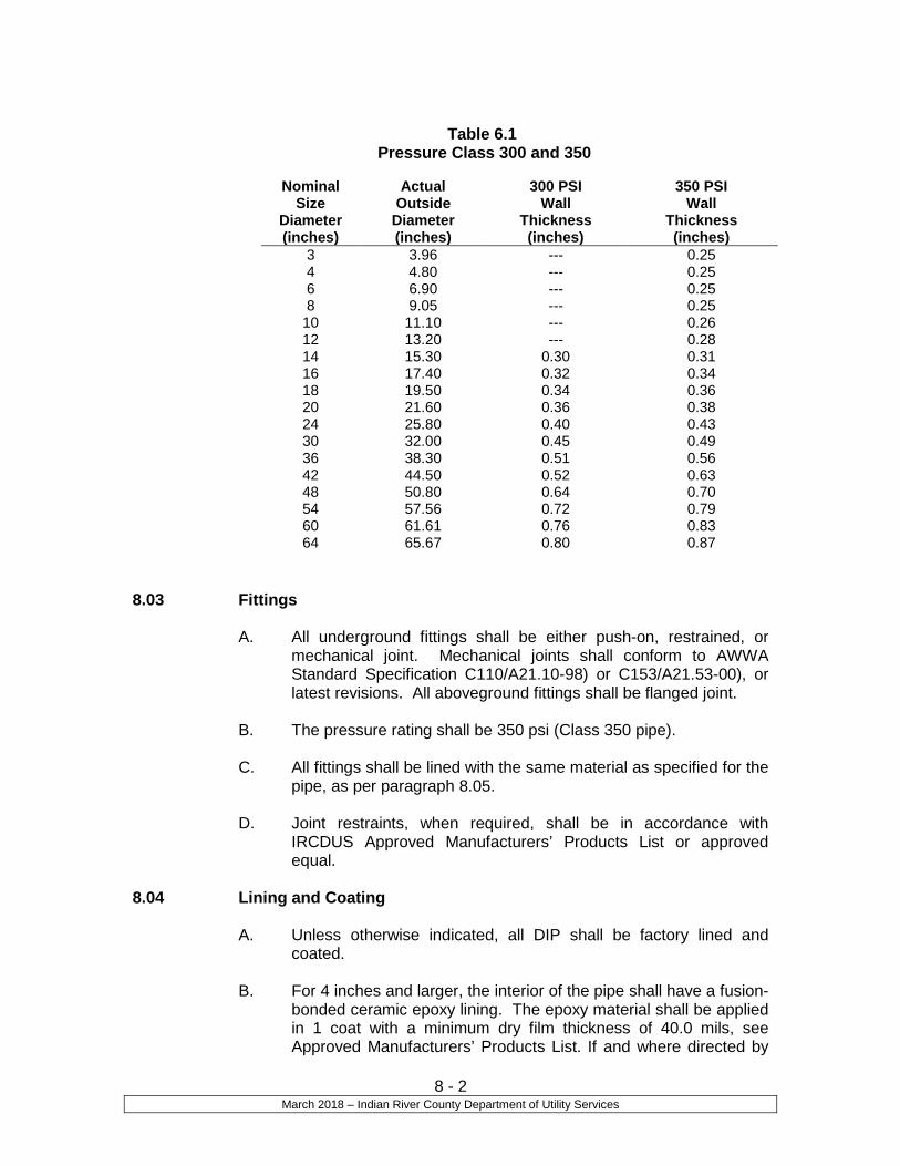
8 - 2 March 2018 – Indian River County Department of Utility Services
Table 6.1
Pressure Class 300 and 350
8.03 Fittings
A. All underground fittings shall be either push-on, restrained, or mechanical joint. Mechanical joints shall conform to AWWA Standard Specification C110/A21.10-98) or C153/A21.53-00), or latest revisions. All aboveground fittings shall be flanged joint.
B. The pressure rating shall be 350 psi (Class 350 pipe).
C. All fittings shall be lined with the same material as specified for the
pipe, as per paragraph 8.05.
D. Joint restraints, when required, shall be in accordance with IRCDUS Approved Manufacturers’ Products List or approved equal.
8.04 Lining and Coating
A. Unless otherwise indicated, all DIP shall be factory lined and coated.
B. For 4 inches and larger, the interior of the pipe shall have a fusion-
bonded ceramic epoxy lining. The epoxy material shall be applied in 1 coat with a minimum dry film thickness of 40.0 mils, see Approved Manufacturers’ Products List. If and where directed by
Nominal Size
Diameter (inches)
Actual Outside
Diameter (inches)
300 PSI Wall
Thickness (inches)
350 PSI Wall
Thickness (inches)
3 3.96 --- 0.25 4 4.80 --- 0.25 6 6.90 --- 0.25 8 9.05 --- 0.25
10 11.10 --- 0.26 12 13.20 --- 0.28 14 15.30 0.30 0.31 16 17.40 0.32 0.34 18 19.50 0.34 0.36 20 21.60 0.36 0.38 24 25.80 0.40 0.43 30 32.00 0.45 0.49 36 38.30 0.51 0.56 42 44.50 0.52 0.63 48 50.80 0.64 0.70 54 57.56 0.72 0.79 60 61.61 0.76 0.83 64 65.67 0.80 0.87

8 - 3 March 2018 – Indian River County Department of Utility Services
IRCDUS, a polyethylene encasement shall be provided over pipes and fittings.
C. Unless otherwise specified, the exterior of the pipe shall have a
bituminous coating to a minimum dry film thickness of 1.0 mil. See IRCDUS Approved Manufacturers’ Products List for coating material.
D. Lining Inspection:
1. All DIP and fitting linings shall be checked for thickness using a magnetic film thickness gauge. The thickness testing shall be done using the method outlined SSPC-PA-2 film thickness rating.
2. The interior lining of all pipe and fittings shall be tested for
pinholes with a nondestructive 2,500-volt test.
3. Each pipe joint and fitting shall be marked with the date of application of the lining system and with its numerical sequence of application on that date.
E. The pipe or fitting manufacturer must supply a certificate attesting
to the fact that the applicator met the requirements of this specification, and that the material used was as specified, and that the material was applied as required by the specification.
F. Anywhere that the coating is removed purposely or accidentally,
the area shall be cleaned of any rust, grease, and dirt and re-coated to a minimum dry film as specified for the individual piece.
G. If and when directed by IRCDUS, a polyethylene encasement
shall be provided around pipe, fittings, and valves. The material, installation, and workmanship shall conform to applicable sections of AWWA Standard Specifications C105/A21.5-99, or latest revision. Installation methods A or B shall be employed using flat tube polyethylene. The Contractor shall make provisions to keep the polyethylene from direct exposure to sunlight prior to installation. Backfilling following installation shall be completed without delay to avoid exposure to sunlight.
8.05 Bell and Spigot Connections
A. Joints in bell and spigot pipe shall be push-on, mechanical, or restrained joints in accordance with AWWA Standard Specifications C111/A21.11-00, or latest revision. Pipe restraints shall also be in accordance with IRCDUS Standards or as directed by IRCDUS.

8 - 4 March 2018 – Indian River County Department of Utility Services
8.06 Flanged Connections
A. All flanged pipe barrels shall comply with the physical and chemical requirements as set forth in the Handbook of Ductile Iron Pipe Research Association. Flanges shall be in accordance with ANSI Specification B16.1 for Class 125 flanges. Bolts shall be stainless and comply with ANSI Specification B18.2.
B. Flanged pipes shall be faced and drilled to the American Standard
Drilling, unless special drilling is called for or required. Where tap or stud bolts are required, flanges shall be tapped. Flanges shall be accurately faced and drilled smooth and true, at right angles to the pipe axis, and shall be covered with zinc dust and tallow or a rust preventive compound immediately after facing and drilling.
C. Flanged pipe with screwed-on flanges shall be furnished with long
hubs, and the flanges shall be screwed on the threaded end of the pipe in the shop and the face of the flange and end of pipe refaced together. There shall be no leakage through the pipe threads and the flanges shall be designed to prevent corrosion of the threads from outside.
D. Flanged joints shall be made with bolts or stud bolts and nuts.
Bolts, stud bolts, and nuts shall conform to American Standard heavy dimensions, semi-finished with square or hexagonal heads and cold punched hexagonal nuts, 316SS. Bolt sizes shall be American Standard for the flanges specified, and bolts and nuts shall have good, true threads.
E. Gaskets shall be in accordance with AWWA Standard
Specifications C115/A21.15-99, or latest revision. 8.07 Submittals
A. Before starting fabrication of the DIP and fittings, the Contractor shall submit one set of complete working drawings (shop drawings) to the Engineer of Record and IRCDUS for approval. Such drawings shall show the pipe, fittings, valves, expansion joints, hangers, supports, and other appurtenances to be installed. Where special fittings are required, they shall be shown in large detail with all the necessary dimensions. The Engineer of Record shall review the drawings and notify IRCDUS of the drawings approved and not approved. IRCDUS shall also review the drawings and coordinate approvals and disapprovals with the Engineer of Record and Contractor. The drawings submitted shall show flanged jointed sections placed so as to be removable without disturbance to the main pipe sections.

8 - 5 March 2018 – Indian River County Department of Utility Services
8.08 Marking
A. Number 10 stranded conductor copper trace wire shall be spiral wrapped or affixed to the top of the pipe. See Trace Wire Details Drawing M-13 for specifications regarding installation.
B. Trace Wire is required over or around all pipes.
C. Location tape is required over all pipes. Tape is to be installed 12”
below proposed finished grade and additional tape adhered directly to top of the pipe if required by IRCDUS engineering.
8.09 Installation
A. Handling and Protection of Pipe: Unless otherwise noted on the drawings or in other sections of this specification, the pipe shall be handled and installed in strict accordance with the manufacturers’ instructions. The Contractor shall use every precaution during construction to protect the pipe against the entry of non-potable water, dirt, wood, small animals, and any other foreign material that would hinder the operation of the pipeline. Where the groundwater elevation is above the bottom of the trench, the Contractor shall provide suitable dewatering equipment at no additional cost to the IRCDUS. All piping shall be placed in a dry trench, unless otherwise approved by IRCDUS.
B. Unless otherwise shown on the drawings, or otherwise authorized by the IRCDUS, all pipe shall have a minimum cover of 36 inches. Contractor shall determine top of pipe elevation and top of ground elevation for every two joints of pipe installed using a level. Pipe must have the minimum cover described above and must be within +/- 0.2 feet of the top of pipe elevation indicated on the drawings. Installed pipe, which does not meet these requirements, shall be reinstalled until it does meet these requirements. Contractor shall record top of pipe and top of ground elevations and the locations of where these elevations were determined and submit this information to IRCDUS. IRCDUS reserves the right to have Contractor excavate and check top of pipe and top of ground elevations to see if they conform to the aforementioned requirements, at no cost to the IRCDUS.
END OF SECTION

Section 9
Reclaimed Water Mains Polyvinyl Chloride (PVC) Pipes and Fittings

9 - 1 March 2018 – Indian River County Department of Utility Services
Section 9
Reclaimed Water Mains Polyvinyl Chloride (PVC) Pipes and Fittings
9.01 General
A. PVC pipe shall be allowed for use as reclaimed water pipe where compatible with the specific conditions of the project. IRCDUS may require the use of material other than PVC during construction permit review or by IRCDUS field personnel during construction, if it is determined that PVC pipe is unsuitable for the particular application.
B. The pipe used for reclaimed mains shall be “purple” in color.
C. PVC pipe shall be identified by its nominal pipe size, plastic pipe
material code, SDR class, pressure rating, ASTM Designation, Manufacturer’s name, production code, and the National Sanitation Foundation seal for potable water (NSF-pw).
9.02 Pipe for Sizes 12 Inches and Smaller in Diameter
A. All pipe intended for conveying or transmitting reclaimed pipe shall be designed for a minimum working pressure of 150 psi.
B. PVC pressure pipe shall conform to AWWA Standards Specifications C900 latest revision, or C909, latest revision and ASTM D1784 and D2241, latest revision. PVC pressure pipe shall be made from Class 12454-A or Class 12454-B material and conform to the outside diameter of cast iron pipe.
C. PVC pressure pipe less than 4” diameter shall be DR-21, PR-200
D. PVC pipe shall be purchased in accordance with IRCDUS Approved Manufacturers’ Products List.
9.03 Pipe and Fittings for Sizes 14 Inches Through 36 Inches in Diameter
A. All pipe and fittings intended for conveying or transmitting reclaimed water shall be designed for a minimum working pressure of 150 psi.
B. PVC pressure pipe shall conform to the latest AWWA Standards
Specifications C900-97 and ASTM D1784, latest revisions. PVC pressure pipe shall be made from Class 12454-A or Class 12454B material and conform to the outside diameter of cast iron pipe with a minimum wall thickness of DR18.
C. PVC pipe shall be purchased in accordance with IRCDUS
Approved Manufacturers’ Products List.

9 - 2 March 2018 – Indian River County Department of Utility Services
9.04 Joints
A. Joints for PVC pressure pipe shall be bell and spigot push-on rubber gasket type only. No solvent weld or threaded joints will be permitted.
B. IRCDUS may consider other type joints for specific installation
upon submission of specifications and approval.
C. Restraint joints, when required, shall be in accordance with IRCDUS Approved Manufacturers’ Products List.
9.05 Fittings
A. All underground fittings shall be either ductile iron push-on, restrained, or mechanical joint. Mechanical joints shall conform to AWWA Standard Specifications C110/A21.10 or C153/A21.53 latest revisions. Fittings shall be fusion-bonded ceramic epoxy lined. The epoxy material shall be applied in one coat with a minimum dry film thickness of 40.0 mils and shall be Protecto 401 or approved equal. All aboveground exposed fittings shall be flanged.
B. The pressure rating shall be 350 psi (Class 350).
C. Joint restraint, when required; shall be in accordance with
IRCDUS Approved Manufacturers’ Products List.
9.06 Submittals
A. Before starting installation of the PVC pipe and fittings, the Contractor shall submit one set of complete working drawings (shop drawings) to the Engineer of Record and IRCDUS for approval. Such drawings shall show the pipe, fittings, valves, hydrants, blowoffs, services, and other appurtenances to be installed. Where special fittings are required, they shall be shown in large detail with all the necessary dimensions. The Engineer of Record shall review the drawings and notify IRCDUS of the drawings approved and not approved. IRCDUS shall also review the drawings and coordinate approvals and disapprovals with the Engineer of Record and Contractor.
9.07 Marking
A. Number 10 stranded conductor copper trace wire shall be spiral wrapped or affixed to the top of the pipe. See Trace Wire Details Drawing M-13 for specifications regarding installation.
B. Trace Wire is required over or around all pipes.

9 - 3 March 2018 – Indian River County Department of Utility Services
C. Location tape is required over all pipes. Tape is to be installed 12” below proposed finished grade and additional tape shall be adhered directly on top of the pipe if required by IRCDUS.
9.08 Storage
A. PVC pipes are not to be stored where exposed to direct sunlight because of possible ultraviolet light degradation. Pipes stored on the jobsite are to be covered. PVC pipes that exhibit discoloration or fading from their original color will be rejected by IRCDUS field representatives.
9.09 Installation
A. Handling and Protection of Pipe: Unless otherwise noted on the drawings or in other sections of these standards, the pipe shall be handled and installed in strict accordance with the manufacturer’s instructions. The Contractor shall use every precaution during construction to protect the pipe against the entry of non-potable water, dirt, wood, small animals, and any other foreign material that would hinder the operation of the pipeline. Where the groundwater elevation is above the bottom of the trench, the Contractor shall provide suitable dewatering equipment at no additional cost to IRCDUS. All piping shall be placed in a dry trench, unless otherwise approved by IRCDUS.
B. Depth of Cover and Pipe Elevation: Unless otherwise shown on
the drawings, or otherwise authorized by IRCDUS, all pipe shall have a minimum cover of 36 inches. Contractor shall determine top of pipe elevation and top of ground elevation for every two joints of pipe installed using a level. Pipe must have the minimum cover described above and must be within +/- 0.2 feet of the top of pipe elevation indicated on the drawings. Installed pipe, which does not meet these requirements, shall be reinstalled until it does meet these requirements. Contractor shall record top of pipe and top of ground elevations and the locations of where these elevations were determined and submit this information to IRCDUS. IRCDUS reserves the right to have Contractor excavate and check top of pipe and top of ground elevations to see if they conform to the aforementioned requirements, at no cost to IRCDUS.
END OF SECTION

Section 10
Submersible Wastewater Pumping Station

10 - 1 March 2018 – Indian River County Department of Utility Services
Section 10
Submersible Wastewater Pumping Station
10.01 General
A. The station shall be complete with pumps, motors, piping, valves, and electrical work, including motor controls, structure, connections and all other needed appurtenances. The station shall be tested and ready for service prior to the sign off or acceptance by IRCDUS.
B. These specifications are intended to give a general description of
what is required, but do not cover all details, which will vary in accordance with the requirements of the equipment as offered. It is, however, intended to cover the furnishing, shop testing, delivery and complete installation and field testing of all materials, equipment and appurtenances for the complete pumping units as herein specified, whether specifically mentioned in these specifications or not.
C. For all units, there shall be furnished and installed all necessary
and desirable accessory equipment and auxiliaries, whether specifically mentioned in these specifications or not, and as required for an installation incorporating the highest standard for the type of service, including field testing of the entire installation and instructing the IRCDUS’s regular operating personnel in the care, operation, and maintenance of all equipment. All Operation and Maintenance Manuals, along with warranty information shall be supplied to IRCDUS.
D. All private lift stations must provide a repair company name and
emergency telephone number on the electrical panel in case of a malfunction of the station. If a name and number is not provided, the IRCDUS reserves the right to call a company of its choosing to make a service call and repair the malfunctioning station. All charges to repair said station shall be charged to the owner of the station.
E. A manhole shall be constructed within 20’ upstream of a lift
station. There shall be only one pipe connection from this manhole to the lift station. The pipe between the lift station and manhole shall be C-900, DR-18 PVC pipe.
F. Paint outside walls, underside of wetwell top slab and valve vault
with two coats of water base epoxy.
10.02 Description of Systems
A. The pump station shall be comprised of a concrete wet well, concrete valve vault, Remote Telemetry Unit (RTU), at least two submersible

10 - 2 March 2018 – Indian River County Department of Utility Services
wastewater pumps and controls, discharge piping and all appurtenances as specified herein or needed. The pump station will pump raw, unscreened, domestic wastewater into a force main.
10.03 Qualification
A. To assure unity of responsibility, the motors and control system shall be furnished and coordinated by the pump manufacturer. The Engineer of Record shall assume responsibility for the satisfactory installation and operation of the entire pumping system, including pumps, motors, and controls as specified.
B. The pumps covered by these specifications are intended to be
standard pumping equipment of proven ability as manufactured by a reputable manufacturer having extensive experience in the production of such pumps. The pumps furnished shall be designed, constructed and installed in accordance with the best practice and methods, and shall operate satisfactorily when installed. Pumps shall be manufactured in accordance with the Hydraulic Institute Standards.
C. The control system shall have an established record of successful
performance for similar service and be approved by IRCDUS.
D. All equipment furnished under this specification shall be new, and shall be the standard product of manufacturers having a successful record of manufacturing and servicing the equipment and systems specified herein for a minimum of five years.
E. The pumps shall be furnished complete with controls and
accessories required, and shall be as on the Approved Manufacturers’ Products List. Grinder pumps shall be permitted for pumps 5.0 HP or less, unless otherwise approved by IRCDUS. Three phase electrical power will be required for all pumping stations. 120/240 volt service will be required for pump stations up to 20 HP. 277/480 volt service will be required for pump stations larger than 20 HP.
10.04 Operating Instructions
A. Operating and maintenance manuals shall be furnished. The manuals shall be prepared specifically for the installation and shall include all required cut sheets, drawings, equipment lists, descriptions, etc., that are required to instruct operating and maintenance personnel unfamiliar with such equipment.
B. An authorized representative of all major component parts of the
lift station, with complete knowledge of proper operation and maintenance, shall be present on start-up of the lift station to instruct IRCDUS personnel on proper operation and maintenance of the station, and to provide operation manuals. If there are

10 - 3 March 2018 – Indian River County Department of Utility Services
difficulties in operation of the equipment due to the manufacturers design or fabrication, the authorized representative shall be responsible for all corrective action to the satisfaction of IRCDUS. This service shall be provided at no cost to IRCDUS.
10.05 Tools and Spare Parts
A. Any special tools required shall be provided. B. The manufacturer shall furnish a complete set of recommended
spare parts necessary for the first three years of operation of the pumping system, which shall include at least the following:
1. 1 set of upper bearings for the pumps 2. 1 set of lower bearings for the pumps 3. 1 set of upper and lower shaft seals for the pumps 4. 1 relay and phase monitor for each type supplied with the
pump control panel for each station 5. Grinder Pump Station (2 Complete Sets) Impeller and
Bottom Plate is one set. 6. Solids Handling Pumps (2 Impellers) 7. 1 –TCU001 Programmed to the corresponding Frequency 8. Impeller puller.
C. Spare parts shall be properly bound and labeled for easy
identification without opening the packaging, and suitably protected for long-term storage.
10.06 Warranty
A. The Contractor and the equipment manufacturers shall warrant all equipment supplied under this section for a period of five years. Warranty period shall commence on final date when IRCDUS accepts the project.
B. The equipment shall be warranted to be free from defects in
workmanship, design and materials. If any part of the equipment should fail during the warranty period, it shall be replaced in the machine(s) and the unit(s) restored to service at no expense to IRCDUS.
C. The manufacturer’s warranty period shall run concurrently with the
Contractor’s warranty period. No exception to the provision shall be allowed.
10.07 Materials and Equipment
A. The pumping units required under this section shall be complete, including pumps and motors with proper alignment and balancing of the individual units. All parts shall be so designed and proportioned as to have liberal strength, stability, and stiffness,

10 - 4 March 2018 – Indian River County Department of Utility Services
and to be especially adapted for the work to be done. Ample room shall be provided for inspection, repairs, and adjustments.
B. Each foundation plate for each pump shall be rigidly and
accurately anchored into position. The same pump manufacturer shall furnish all necessary foundation bolts, plates, nuts, and washers for installation by the Contractor. Each foundation plate shall be ½” thick Type 316 stainless steel. Foundation bolts, nuts, washers, and spare parts shall be Type 316 stainless steel.
C. Stainless steel nameplates giving the name of the manufacturer,
head, speed, and all other pertinent data shall be attached to each pump and motor.
10.08 Pumps
A. General 1. The pumps shall be totally submersible centrifugal pumps
with close-coupled motors designed to pump sewage. The design shall be such that the pumping units shall be automatically connected to the discharge piping when lowered into place on the discharge connection. The pumps shall be easily removable for inspection or service, requiring no bolts, nuts or other fastenings to be removed for this purpose, or need for personnel to enter the wet well. Each pump shall be fitted with a 316 stainless steel lifting cable of adequate strength, and shall be five (5) feet longer than wet well depth to control panel to permit raising the pump for inspection and removal.
2. The impeller shall be constructed of nodular iron SP
(spheroidal graphite). The hydraulic design shall incorporate a single vane centrifugal impeller. The design shall permit low liquid velocities and gradual acceleration and change of flow direction of the pumped media. The impeller/casing design shall result in a passage free of surfaces to which solid or fibrous materials can adhere. The overall pump design shall combine high efficiency, low required Net Positive Suction Head (NPSH), large ball passage and the ability to handle high solids concentrations efficiently. All other parts shall be of close grain gray iron construction, with all parts coming into contact with sewage protected by a coat of rubber-asphalt paint. All external bolts and nuts shall be of Type 316 stainless steel. The impeller shall be of a centrifugal type, capable of passing 3-inch minimum diameter solids, fibrous material, and heavy sludge. If riser pipes are less than 3 inches in diameter in the wet well, then the pumps must be grinder pumps.
10 - 5 March 2018 – Indian River County Department of Utility Services
3. Each pump shall be provided with a tandem double mechanical seal running in an oil reservoir, composed of two separate lapped face seals, each consisting of one stationary and one rotating tungsten-carbide or silicon carbide ring with each pair held in contact by a separate spring, so that the outside pressure assists spring compression in preventing the seal faces from opening. The compression spring shall be protected against exposure to the pumped liquid. The pumped liquid shall be sealed from the oil reservoir by one face seal and sealed from the oil reservoir from the motor chamber by the other. The seals shall require neither maintenance nor adjustment, and shall be easily replaced. Conventional double mechanical seals with a single spring between the rotating faces, requiring constant differential pressure to effect sealing and subject to opening and penetration by pumping forces, shall not be considered equal to tandem seal specified and required.
4. A sliding guide bracket shall be an integral part of the
pumping unit, and the pump casing shall have a machined connecting flange to connect with the cast iron discharge connection, which shall be bolted to the floor of the wet well with stainless steel anchor bolts and so designed as to receive the pump connection without the need of any bolts or nuts. Sealing of the pumping units to the discharge connection shall be accomplished by a simple linear downward motion of the pump, with the entire weight of the pumping unit guided by 316 stainless steel guide rails which will press it tightly against the discharge connection. No portion of the pump shall bear directly on the floor of the sump, and no rotary motion of the pump shall be required for sealing.
5. Pump motors shall be housed in an air-filled, watertight
casing. Motors shall be a NEMA Design B with a 1.15 service factor. Insulation shall be moisture-resistant NEMA Class F with a maximum temperature rise of 90 degrees Celsius above ambient temperature (4 degrees Celsius). Motor characteristics are noted on the Drawings. Pump motors shall have cooling characteristics suitable to permit continuous operation, in a totally, partially or non-submerged condition. Each motor shall incorporate an ambient temperature compensated overheat sensing device and a moisture sending device wired in series. The protective devices shall be wired into the pump controls in such a way that if either device operates, the pump will shut down. The devices shall be self-resetting. The cable shall be fixed to the pump using a watertight trumpet assembly. The pump shall be capable of running continuously in a totally dry condition under full load,
10 - 6 March 2018 – Indian River County Department of Utility Services
without damage, for extended periods. Before final acceptance, a field running test demonstrating this ability, with four hours of continuous operation (water supplied by the contractor) under the above conditions, shall be performed for all pumps being supplied, if required by the IRCDUS. Pump motor cables shall be suitable for submersible pump applications and shall be properly sealed.
6. Motor windings shall be treated with a mildew preventative.
B. Each pumping unit and its driving equipment shall be designed
and constructed to withstand the maximum turbine runaway speed of the unit due to backflow through the pump.
C. Performance Requirements, refer to IRCDUS Standards, Pumping
Station Data Table on Drawing No. S-21.
10.09 Access and Frame Guides A. The pumping station shall be furnished with the necessary
aluminum access frames, complete with hinged and hasp-equipped covers, stainless steel upper guide rail holder, power cable holder and level sensor cable holder. The frames shall be securely mounted above the pumps. Access covers shall have safety locking handles in open position. Access covers shall be of aluminum-checkered plate with 316 stainless steel hinges and hardware. The access cover and frame shall be as sized on the Drawings.
B. Lower guide rail holders shall be integral with the discharge
connection. Guide rails shall be of Schedule 40, 2” Welded 316 stainless steel pipe of the size indicated on the Approved Drawings and of the length required by the pump manufacturer.
C. A safety grate with 316 stainless steel hardware is required for all wet wells and shall be in accordance with IRCDUS Approved Manufacturers’ Products List.
10.10 Pump Control System-Manual System (Non-remote Telemetry Unit)
A. General
1. A pump controller shall be provided for the wastewater
pumping station. The controller shall respond to the liquid level sensor to automatically start and stop pumps to pace pump station influent flow, and shall be approved by IRCDUS.
2. The pump controller shall be the standard system of the
manufacturer as modified for this application. The wet well

10 - 7 March 2018 – Indian River County Department of Utility Services
levels to be used in operation are as shown on Detail Drawings S-15 and S-21 of the IRCDUS Standards.
B. Operation Requirements
1. The control panels shall consist of a main circuit breaker and generator breaker with mechanical interlock, an emergency generator receptacle, a motor control breaker (MCB) and magnetic starter for each pump motor, and 20 ampere, 120/240 volt circuit breakers as required. The motor control panel (MCP) shall meet all requirements of service entrance by properly bonding neutral or shall be Underwriters Laboratories service entrance rated. A low and high level alarm and pump shutoff shall be accomplished by float type, liquid level control system, with all components mounted in one common enclosure. Control switches shall provide means to operate each pump manually or automatically. When operated in the automatic mode, the control assembly shall provide means to manually select or automatically alternate the position of the “lead” and “lag” pumps after each pumping cycle. A three position alternate switch labeled “hands-off-auto” (H-O-A) shall be provided to manually select which pump shall be the lead pump, when necessary, and also be able to test the alternator to see if it is still operational.
2. A float type liquid level control system shall continuously
monitor wet well liquid level and control operation of the low-level cutoff for the pumps, and shall operate on a 24-volt circuit.
3. A non-fused safety switch shall be installed between the
meter and panel. This switch shall be in a NEMA 4X, UL rated, stainless steel waterproof enclosure, in accordance with IRCDUS Approved Manufacturers’ Products List. Amperage shall be at least equal to that of the main breaker.
C. Construction
1. The electrical control equipment shall be mounted within a
modified NEMA 4X, UL rated, white powder coated stainless steel (316), dead front enclosure. The enclosure shall be equipped with a door and may incorporate a removable back panel on which control components shall be mounted. Back panel shall be secured to enclosure with collar studs. All lines entering the enclosure shall be protected by conduit seal bushings (supplied by pump manufacturer) at the source and shall be behind the dead front enclosure, entering from the side or bottom only. The seals shall prevent moisture and gas from entering the

10 - 8 March 2018 – Indian River County Department of Utility Services
enclosure. Two cable connectors (shall be in accordance with IRCDUS Approved Manufacturers’ Products List) shall be provided to terminate the motor cables in the control panel. The connectors shall be suitable for a 2” conduit with a seal bushing suitable for the motor cables.
2. Components
a. All motor branch circuit breakers, motor starters,
and control relays shall be of highest industrial quality, securely fastened to the removable back panels with screws and lock washers. Back panels shall be tapped to accept all mounting screws. Self-tapping screws shall not be used to mount any component. A non-corrosive material shall be utilized for wire connection locations within the box.
b. A thermal-magnetic air circuit breaker, per
Approved Manufacturers’ Products List, shall be furnished for the main breaker. The manufacturer shall seal all circuit breakers after calibration to prevent tampering. A Motor Control Breaker (MCB) shall be provided for each motor starter. Each MCB shall be adequately sized to meet the pump motor and station operating conditions.
c. An open frame, across-the-line, NEMA rated,
magnetic motor starter, Class 8536, in accordance with IRCDUS Approved Manufacturers’ Products List, shall be furnished for each pump motor. Reduced voltage motor starters, Class 8606, per Approved Manufacturers’ Products List, are required for all 30 HP and larger motors. All motor starters shall be equipped to provide under-voltage release and overload protection on all three phases. Motor starter contacts shall be easily replaceable without removing the motor starter from its mounted position. Overload reset push buttons shall be located on the inside of the control compartment door.
d. An emergency generator receptacle (EGR) shall be
installed in the side of the control panel and connected to the line side of the generator breaker. The receptacle shall be in accordance with IRCDUS Approved Manufacturers’ Products List.
e. A ground fault interrupter (GFI) duplex utility
receptacle providing 120 volt, 20 amp, 60 hertz, single phase current shall be mounted on the internal door.

10 - 9 March 2018 – Indian River County Department of Utility Services
f. The control panel shall include an adjustable time
delay relay to prevent both pumps from starting simultaneously. Time delay relays shall be electronic type.
3. Operating Controls and Instruments
a. All operating controls and instruments shall be securely mounted on the control compartment door. All controls and instruments shall be clearly labeled to indicate function.
b. Pump mode selector switches shall be Hand-Off-
Auto type to permit override of automatic level control and manual actuation of shutdown of either pump motor. Operation of pumps in manual mode shall bypass all safety shutdown circuits except pump motor overload shutdown. Switches shall be oil-tight, in accordance with IRCDUS Approved Manufacturers’ Products List, providing three switch positions, each of which shall be clearly labeled according to function. Separate indicator lamps, which shall operate at 115 volts input, shall be provided mounted above H.O.A. selector switches. Lamps shall be easily replaceable from the front of control compartment door without removing switch modules from their mounted positions.
c. Indicator lamps shall be mounted in oil-tight
modules, in accordance with IRCDUS Approved Manufacturers’ Products List. Lamp modules shall be equipped to operate at 115-volt input. Lamps shall be easily replaceable from the front of the control compartment door without removing lamp module from its mounted position.
d. A six digit, non-reset elapsed time meter shall be
connected to each motor starter to indicate the total running time of each pump in “hours” and “tenth of hours.” The elapsed time meters shall be in accordance with IRCDUS Approved Manufacturers’ Products List.
10.11 Pump Control System (Remote Telemetry Unit)
A. A Remote Telemetry Unit (RTU) shall be supplied with the pump control system. The RTU shall be capable of acquiring analog and discrete data for transmission to the Central Telemetry Unit (CTU). The RTU shall also be capable of receiving instructions from the

10 - 10 March 2018 – Indian River County Department of Utility Services
CTU for the operation of the pumps. See IRCDUS Approved Manufacturers’ Products List for the separate components.
10.12 Shop Painting
A. Before exposure to weather and prior to shop painting, all surfaces shall be thoroughly cleaned, dry and free from all mill-scale, rust, grease, dirt and other foreign matter.
B. All pumps and motors shall be shop primed with primer
compatible with the field painting.
C. All nameplates shall be properly protected during painting.
D. Gears, bearing surfaces, and other similar surfaces obviously not to be painted shall be given a heavy shop coat of grease or other suitable rust-resistant coating. This coating shall be maintained as necessary to prevent corrosion during periods of storage and erection, and shall be satisfactory to IRCDUS up to the time of final acceptance test.
E. Control Panels shall be made of stainless steel (316).
10.13 Field Painting
A. The primer and paint used in the shop shall be products of the same manufacturer as the field paint to assure compatibility.
B. All nameplates shall be properly protected during painting.
10.14 Lift Station- General
A. The Lift Station Wet Wells shall conform to the following size:
Depth (ft) Diameter (ft)
0-10 6 11-15 8
16-20 10 21-25 12
or as approved by IRCDUS’s Engineer.
10.15 Lift Station Liners-General
A. A protective liner for the concrete shall be installed in the lift
station/wet wells, re-pump lift stations, receiving manholes, drop manholes, and manholes as required by IRCDUS.
B. After the lift station lining operation has been completed, the
Contractor in the presence of the IRCDUS’s representative shall visually inspect the lift station. In addition, at IRCDUS request, the

10 - 11 March 2018 – Indian River County Department of Utility Services
Contractor shall be required within one year to visually inspect the lift stations that were lined. The Contractor shall redo any work that has become defective.
10.16 Lift Station Liners- HDPE
A. The Lift Station Liner shall be High Density Polyethylene (HDPE) with a minimum thickness of 2 mm. All HDPE liner sheets shall be extruded with a large number of anchoring studs, a minimum of
, manufactured during the extrusion process in one piece
with the sheet so there is no welding and no mechanical finishing work to attach the studs to the sheet. The liner shall have a pull out of 112.5 lbs./anchoring stud.
B. Flat liner sheet, non anchored, used for overlapping joints, shall
have a minimum thickness of 3mm. All joints shall be sealed by means of thermal welding performed by certified welders.
C. The lining shall have good impact resistance, shall be flexible, and
shall have an elongation sufficient to bridge up to a 1/4-inch settling crack, without damage to the lining. The liner shall be able to bridge any expansion cracks that may occur.
D. Lining shall be repairable at any time during the life of the
structure. E. A certified fabricator shall custom fit the liner to the form work in
order to protect the concrete surfaces from sewer gases. The interior surfaces to be protected shall include the walls, ceiling, and pipe entries.
F. For all lined manholes the use of HDPE Grade rings shall be used
in lieu of brick or precast grade rings. Grade rings shall meet HS-25 load rating. Butyl sealant shall be used between each ring to make a watertight joint. The first grade ring shall be welded to the liner to provide a gas tight seal.
C. Upon request, the manufacturer shall provide written certification
that the liner used meets or exceeds the requirement of this specification.
D. Provide a five year unlimited warranty on all workmanship and
products. The work includes the surface preparation and application of the liner system, shall protect the structure for at least five years from all leaks, and from failure due to corrosion from exposure to corrosive gases such as hydrogen sulfide.

10 - 12 March 2018 – Indian River County Department of Utility Services
10.17 Lift Station Liners – Fiberglass A. The lift station liner shall meet all requirements of ASTM
Specifications D-3753 for glass fiber reinforced polyester manholes or lift stations. See IRCDUS Approved Manufacturers’ Products List
C. Fiberglass liners shall have a three year warranty period.
END OF SECTION

Section 11
Miscellaneous Valves and Appurtenances

11 - 1 March 2018 – Indian River County Department of Utility Services
Section 11
Miscellaneous Valves and Appurtenances 11.01 General
A. All of the types of valves and appurtenances shall be on the IRCDUS Approved Manufacturers’ Products List.
B. All valves and appurtenances shall be designed, constructed, and
installed in accordance with the best practices and methods and shall comply with these specifications as applicable.
C. All valves and appurtenances shall have the name of the
manufacturer, year manufactured, and the working pressure for which they are designed cast in raised letters upon some appropriate part of the body.
D. All buried valves and appurtenances shall be mechanical joint. All
aboveground/exposed valves and appurtenances shall be flanged.
E. Gate valves shall be used on water, sewer, reclaimed, and brine mains.
F. Plug valves may be used in lift station valve vaults as approved by
IRCDUS.
G. IRCDUS, on a case-by-case basis, may approve valves and appurtenances other than those specifically called out in this Section for use. Criteria for approval shall include the interchangeability of the valve or appurtenance, or its parts, with those brands specifically called out in these specifications.
H. All exposed valves and appurtenances shall be painted in
accordance with IRCDUS Approved Manufacturers’ Products List. Water mains shall be painted blue, force mains shall be painted “green”, reuse mains shall be painted “purple” and brine shall be painted “brown”.
11.02 Gate Valves – 3 Inches and Larger
A. All buried gate valves shall meet the requirements of AWWA Standard Specification C509-C515, or latest revision. Valves shall be rated for 150-psi working pressure and a minimum 300-psi test pressure. Valves shall be ductile iron body, bronze-mounted, resilient seated, non-rising stem type fitted with “O-Ring” seals. All bolts to be used in valve bonnet are to be 316 stainless steel. The operating nuts shall be Standard AWWA 2” square. All valves shall open counterclockwise. Stuffing boxes shall be the “O-Ring” type. Gate valves shall be mechanical joint, ANSI Standards 21.11, except where shown otherwise.

11 - 2 March 2018 – Indian River County Department of Utility Services
B. Gate valves shall be provided with a valve box, cover, and
concrete pad. Box cover opening shall be for valve stem and nut. The Contractor shall provide valve wrenches and extension stems from the same manufacturer as the valve to actuate the valves. The box and cover shall be in accordance with IRCDUS Approved Manufacturers’ Products List. (See Drawing M-5 and M-6 for details on the valve box, cover, and concrete pad.)
11.03 Check Valves
A. Check valves for ductile iron pipelines shall be swing type and shall meet the material requirements of AWWA Standard Specifications C508-01, or latest revision. The valves shall be iron body, bronze mounted, single disc, 150 psi working water pressure, non-shock, and non-slam, slow closing, and hydrostatically tested at 300 psi. Ends shall be 125 pound ANSI B16.1 flanges or 125 pound ANSI B2.1 threaded fittings, depending upon location.
B. When there is no flow through the line, the disc shall hang lightly
against its seat. When open, the disc shall swing clear of the waterway.
C. Check valves shall have bronze seat and body rings, extended
bronze hinge pins, and bronze nuts on the bolts of bolted covers.
D. Valves shall be so constructed that disc and body seat may easily be removed and replaced without removing the valve from the line. Valves shall be fitted with an extended hinge arm with outside lever and weight, as necessary.
E. Check valves for PVC pipe less than 3” in diameter shall be of
PVC Type 1, Series BC, with union, socket, threaded, or flanged ends, as required and shall be per the Approved Manufacturers’ Products List.
11.04 Plug Valves
A. Plug valves shall be non-lubricated eccentric type with semi-steel bodies, resilient faced plugs, and stainless steel or nickel seats in the body. Port area shall be at least 80 percent of full pipe area for valves 20 inches and smaller. Port area shall be 70 percent for all valves 24 inches and larger. All valves 4 inches and larger shall be of the bolted design. All exposed nuts, bolts, springs, and washers shall be hot dipped galvanized, except exposed hardware for submerged valves shall be of stainless steel. Valve bodies shall be semi-steel with 125-pound ANSI Standard flanged ends for interior or aboveground service; mechanical joint for buried service and for use with threaded cast iron or ductile iron piping shall have screwed end connections. The plug shall be one
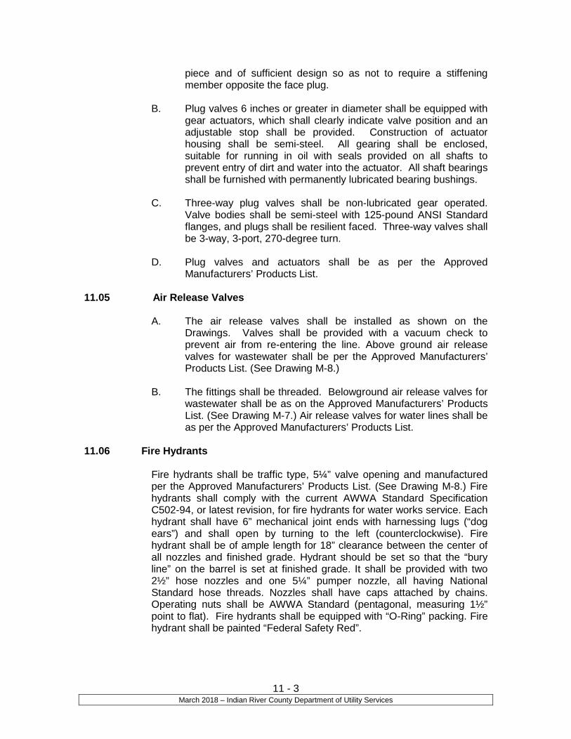
11 - 3 March 2018 – Indian River County Department of Utility Services
piece and of sufficient design so as not to require a stiffening member opposite the face plug.
B. Plug valves 6 inches or greater in diameter shall be equipped with
gear actuators, which shall clearly indicate valve position and an adjustable stop shall be provided. Construction of actuator housing shall be semi-steel. All gearing shall be enclosed, suitable for running in oil with seals provided on all shafts to prevent entry of dirt and water into the actuator. All shaft bearings shall be furnished with permanently lubricated bearing bushings.
C. Three-way plug valves shall be non-lubricated gear operated.
Valve bodies shall be semi-steel with 125-pound ANSI Standard flanges, and plugs shall be resilient faced. Three-way valves shall be 3-way, 3-port, 270-degree turn.
D. Plug valves and actuators shall be as per the Approved
Manufacturers’ Products List.
11.05 Air Release Valves
A. The air release valves shall be installed as shown on the Drawings. Valves shall be provided with a vacuum check to prevent air from re-entering the line. Above ground air release valves for wastewater shall be per the Approved Manufacturers’ Products List. (See Drawing M-8.)
B. The fittings shall be threaded. Belowground air release valves for
wastewater shall be as on the Approved Manufacturers’ Products List. (See Drawing M-7.) Air release valves for water lines shall be as per the Approved Manufacturers’ Products List.
11.06 Fire Hydrants
Fire hydrants shall be traffic type, 5¼” valve opening and manufactured per the Approved Manufacturers’ Products List. (See Drawing M-8.) Fire hydrants shall comply with the current AWWA Standard Specification C502-94, or latest revision, for fire hydrants for water works service. Each hydrant shall have 6” mechanical joint ends with harnessing lugs (“dog ears”) and shall open by turning to the left (counterclockwise). Fire hydrant shall be of ample length for 18” clearance between the center of all nozzles and finished grade. Hydrant should be set so that the “bury line” on the barrel is set at finished grade. It shall be provided with two 2½” hose nozzles and one 5¼” pumper nozzle, all having National Standard hose threads. Nozzles shall have caps attached by chains. Operating nuts shall be AWWA Standard (pentagonal, measuring 1½” point to flat). Fire hydrants shall be equipped with “O-Ring” packing. Fire hydrant shall be painted “Federal Safety Red”.

11 - 4 March 2018 – Indian River County Department of Utility Services
11.07 Backflow Preventers
All backflow preventers shall be mounted aboveground, in non-traffic areas on the customer’s side of the meter. Aboveground piping shall be ductile iron. Brass or Copper pipe may be used for pipe 2” in diameter or smaller. Backflow preventers shall be of reduced pressure/double check type with two (2) independently operating check valves, and shall be designed to operate in a horizontal flow mode. An independent relief valve shall be located between the two check valves. Reduced pressure feature shall be included in all commercial applications. Preventers shall be University of Southern California (USC) approved as per the Approved Manufacturers’ Products List.
11.08 Valve Boxes
A. All buried valves shall have cast iron two or three-piece valve boxes with cast iron covers. Valve boxes shall be provided with suitable heavy bonnets and extend to match finished grade surface as directed by the Engineer. The barrel shall be one or two-piece, screw or slide type, having 5¼” shaft. Covers shall have “WATER” cast into the top for all water mains, “SEWER” cast into the top for all wastewater force mains and “REUSE” cast into the top for all reuse mains. All valves shall have actuating nuts extended to within 24 inches of the top of the valve box cover. (See Drawing M-5.)
B. Valve boxes shall be provided with a concrete pad around the top
of the box. A nameplate with a suitable anchor for casting in concrete shall be installed in valve pads in unpaved areas. Nameplate shall be 3” diameter brass disk with engraved lettering 1/8” deep, as shown on the Drawing M-6 and manufactured per the Approved Manufacturers’ Products List.
C. A 3” diameter wire port box to house the trace wire shall be
installed in valve boxes in unpaved areas. D. Valve boxes shall be installed in a concrete pad, as specified in
Drawings Detail M-5 & M-6.
11.09 Corporation Stops
A. Corporation stops for connections to ductile iron or P.V.C. piping shall be all brass or bronze suitable for 150 psi operating pressure, shall be iron pipe or AWWA tapered thread design, shall be as per the Approved Manufacturers’ Products List, and shall be of sizes required and/or noted on the Drawings.
B. Saddles shall have stainless steel or no lead brass double strap as
per the Approved Manufacturers’ Products List.

11 - 5 March 2018 – Indian River County Department of Utility Services
11.10 Flexible Couplings
A. Flexible couplings shall be either the split type or the sleeve type.
1. Split type coupling shall be used with all interior piping and with exterior piping as noted. The couplings shall be mechanical type for radius groove piping. The couplings shall mechanically engage and lock grooved pipe ends in a positive couple and allow for angular deflection and contraction and expansion.
2. Couplings shall consist of ductile iron, ASTM Specification
A47, Grade 32510 housing clamps in two or more parts, a single chlorinated butyl composition sealing gasket with a “C” shaped cross-section and internal sealing lips projecting diagonally inward, and two or more oval track head type bolts with hexagonal heavy nuts conforming to ASTM Specification A183 and A194 to assemble the housing clamps. Bolts and nuts shall be 316 stainless steel.
3. Sleeve type couplings shall be used with all buried piping.
The couplings shall be of ductile iron and shall be per the Approved Manufacturers’ Products List. The coupling shall be provided with 316 stainless steel bolts and nuts, unless indicated otherwise.
4. All couplings shall be furnished with the pipe stop
removed.
5. Couplings shall be provided with gaskets of a composition suitable for exposure to the liquid within the pipe.
6. Ductile iron followers and middle rings conform to ASTM A-
536, Grade 65-45-12, NSF-61 fusion bonded powder epoxy coating, testing per AWWA C-219 (ANSI A21-11), rating 200 psi working pressure per AWWA C-219, compounded gaskets conform to compression test ASTM D-395 Method A & B, approved for water application.
11.11 Steel Casing Pipe
A. Steel casings shall conform to the requirements of ASTM Designation A139 Grade “B” with a minimum yields strength of 35,000 psi and shall be coated inside and outside by a black bituminous coating, minimum 5 mils thick. The casing pipes shall have the minimum nominal diameter and wall thickness as indicated below.

11 - 6 March 2018 – Indian River County Department of Utility Services
Casing Pipe Casing Pipe Inside Diameter Wall Thickness Inches Inches _____________________________________ 6-16 .250 18-20 .312 22-24 .375 26-28 .437 30-34 .500 36-38 .562 40-50 .625 52-58 .750 60-78 .813 84-90 .875 96-102 .937 108-114 1.000 120 1.125
B. Field and shop welds of the casing pipes shall conform to the American Welding Society Standard Specifications. Field welds shall be complete penetration, single-vee groove or single-bevel groove type joints.
11.12 Tapping Sleeves and Valves
A. Tapping sleeve and valves shall be stainless steel wraparound type or ductile iron on potable water mains. IRCDUS shall direct the contractor which type to be used. Tapping sleeve and valves shall be stainless steel wraparound type for wastewater force mains and reuse water mains per the Approved Manufacturers’ Products List.
C. For all force main taps, a minimum 4” tap is required.
11.13 Curb Stops and Angle Meter Stops
A. Curb stops and angle meter stops shall be per Approved Manufacturers’ Products List.
END OF SECTION

Section 12
Aerial Crossings

12-1 March 2018 – Indian River County Department of Utility Services
Section 12
Aerial Crossings - New and/or Replacement
12.01 General
A. There are two industry-accepted methods of constructing aerial crossings: ductile
iron and welded steel. Joints are usually constructed using flanges or push-on
pipe. In the case of ductile iron, flanges are screwed onto the pipe. For steel
pipe, all flanges are to be factory welded. No field welding is allowed.
B. Where there is a new or existing utility bridge shelf, the aerial crossing shall be
constructed of flanged or push-on Ductile Iron Pipe (D.I.P). The crossing shall be
constructed in place on concrete cradles. Pre-assembly of ductile iron pipe and
then lifting into place will not be allowed. DIP shall be saw cut only; no torch
cutting is allowed.
C. Where there is a bridge hanger installed for the aerial crossing, steel pipe with
factory welded flanges shall be used. All flanges are to be joined using 316
stainless steel bolts, nuts and washers. The steel pipe crossing will be
preassembled and then lifted into place onto the hangers. If the total span length
is such that it cannot be shipped without special conditions, the span shall be
constructed in two or more sections having factory-welded flanges on both ends.
12.02 Pipe
A. DIP specifications for ductile iron utility pipe are given in Sections 1 and 4 of the
standards.
B. Steel pipe for aerial crossings shall be the size as shown on construction plans
and shall be in shop-finished lengths. No field cutting and fitting will be allowed. If
no plans are available, it will be specified by the design engineer. If an existing
aerial pipe is to be replaced and exact finished length cannot be determined
without lifting the steel section into place for measurement, the flanged steel
section length will be estimated and assembled leaving it about 3 feet short of the
total span length. A 5 to 10 feet section of flanged DIP shall be secured to the
end of the steel flange for measurement and cut to fit. The plain end of the DIP
will be secured to a mechanical joint fitting using a gasket and mega lug restraint.
C. Pipe shall be seamless carbon steel pipe ASTM A53, Grade B, Schedule 80 with
a circumferential weld meeting the requirements of AWWA Standard C200 “Steel
Water Pipe 6” and Larger”. Steel Pipe and Flanges (welded to the pipe by the
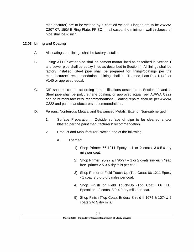
12-2 March 2018 – Indian River County Department of Utility Services
manufacturer) are to be welded by a certified welder. Flanges are to be AWWA
C207-07, 150# E-Ring Plate, FF-SO. In all cases, the minimum wall thickness of
pipe shall be ½ inch.
12.03 Lining and Coating
A. All coatings and linings shall be factory installed.
B. Lining: All DIP water pipe shall be cement mortar lined as described in Section 1
and sewer pipe shall be epoxy lined as described in Section 4. All linings shall be
factory installed. Steel pipe shall be prepared for linings/coatings per the
manufacturers’ recommendations. Lining shall be Tnemec Pota-Pox N140 or
V140 or approved equal.
C. DIP shall be coated according to specifications described in Sections 1 and 4.
Steel pipe shall be polyurethane coating, or approved equal, per AWWA C222
and paint manufacturers’ recommendations. Coating repairs shall be per AWWA
C222 and paint manufacturers’ recommendations.
D. Ferrous, Nonferrous Metals, and Galvanized Metals; Exterior Non-submerged:
1. Surface Preparation: Outside surface of pipe to be cleaned and/or
blasted per the paint manufacturers’ recommendation.
2. Product and Manufacturer-Provide one of the following:
a. Tnemec:
1) Shop Primer: 66-1211 Epoxy – 1 or 2 coats, 3.0-5.0 dry
mils per coat.
2) Shop Primer: 90-97 & H90-97 – 1 or 2 coats zinc-rich “lead
free” primer 2.5-3.5 dry mils per coat.
3) Shop Primer or Field Touch-Up (Top Coat): 66-1211 Epoxy
- 1 coat, 3.0-5.0 dry miles per coat.
4) Shop Finish or Field Touch-Up (Top Coat): 66 H.B.
Epoxoline - 2 coats, 3.0-4.0 dry mils per coat.
5) Shop Finish (Top Coat): Endura-Shield II 1074 & 1074U 2
coats 2 to 5 dry mils.
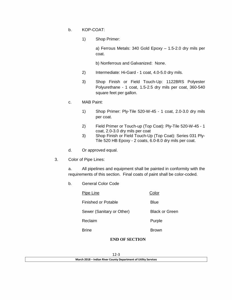
12-3 March 2018 – Indian River County Department of Utility Services
b. KOP-COAT:
1) Shop Primer:
a) Ferrous Metals: 340 Gold Epoxy – 1.5-2.0 dry mils per
coat.
b) Nonferrous and Galvanized: None.
2) Intermediate: Hi-Gard - 1 coat, 4.0-5.0 dry mils.
3) Shop Finish or Field Touch-Up: 1122BRS Polyester
Polyurethane - 1 coat, 1.5-2.5 dry mils per coat, 360-540
square feet per gallon.
c. MAB Paint:
1) Shop Primer: Ply-Tile 520-W-45 - 1 coat, 2.0-3.0 dry mils
per coat.
2) Field Primer or Touch-up (Top Coat): Ply-Tile 520-W-45 - 1 coat, 2.0-3.0 dry mils per coat
3) Shop Finish or Field Touch-Up (Top Coat): Series 031 Ply-Tile 520 HB Epoxy - 2 coats, 6.0-8.0 dry mils per coat.
d. Or approved equal.
3. Color of Pipe Lines:
a. All pipelines and equipment shall be painted in conformity with the
requirements of this section. Final coats of paint shall be color-coded.
b. General Color Code
Pipe Line Color
Finished or Potable Blue
Sewer (Sanitary or Other) Black or Green
Reclaim Purple
Brine Brown
END OF SECTION

Section 13
Testing and Inspection of Water Mains, Reclaimed Mains, Wastewater Force Mains, and Gravity Sewer Lines

13 - 1 March 2018 – Indian River County Department of Utility Services
Section 13
Testing and Inspection of Water Mains, Reclaimed Mains, Wastewater Force Mains, and Gravity Sewer Lines
13.01 Pressure and Leakage Tests of Underground Pressure Piping
A. No hydrostatic testing will be permitted until record drawings have been submitted and approved by IRCDUS.
B. Prior to conducting pressure and leakage tests, all new water and
reclaimed water pipelines shall be full bore flushed (see Drawing W-9) and all pipelines including wastewater force mains shall be thoroughly cleaned to remove all dirt, stones, pieces of wood, and any other materials that may have entered the pipeline during construction, and all dirty water and/or discolored water from the pipelines. After this cleaning, if any obstructions remain, they shall be removed. All debris cleaned from the pipelines shall be removed from the job site. Hydrostatic pressure and leakage tests shall conform to AWWA Standard Specifications C-605-94, or latest edition, for PVC pipe. Hydrostatic pressure and leakage tests shall conform to AWWA Standard Specifications C-600-99, or latest revision, for DIP. The Contractor shall furnish all gauges, meters, pressure pumps and other equipment needed to test the line. IRCDUS shall be present during all testing, televising, and final inspections.
The pressure required for the field hydrostatic pressure test shall be not less than 150 psi for water mains, reclaimed water mains and for sewer force mains. The Contractor shall provide temporary plugs and blocking necessary to maintain the required test pressure. Corporation cocks at least 1 inch in diameter, pipe riser and angle globe valves shall be provided at each pipe dead-end in order to bleed air from the line. Duration of pressure test shall be at least 2 hours. Allowable amount of makeup water for expansion during the pressure test of the pipe shall conform to Plastic Pipe Institute (PPI) Handbook of Polyethylene Pipe; Inspection, Tests, and Safety Considerations, unless otherwise approved by IRCDUS. The Operating Safety Considerations, Post Installation, Hydrostatic Testing, Monitored Make-up Water Test, Table III, is on Pages 24 and 25 of the Handbook.
C. The leakage test may be conducted concurrently with the hydrostatic
pressure test and shall be of not less than 2 hours duration. All leaks evident at the surface shall be repaired and leakage eliminated regardless of total leakage as shown by test. Lines that fail to meet tests shall be repaired and re-tested as necessary until satisfactory test requirements are complied. Defective materials, pipes, valves and accessories shall be removed and replaced. The pipelines shall be tested in such sections as may be directed by IRCDUS by shutting valves or installing temporary plugs as required. The line shall be filled with water and all air removed and the test pressure shall be maintained in the pipe for the entire test period by means of a force pump to be furnished by the

13 - 2 March 2018 – Indian River County Department of Utility Services
Contractor. Accurate means shall be provided for measuring the water required to maintain this pressure. The amount of water required is a measure of the leakage. Testing shall be in accordance with the applicable provisions as set forth in Section 13 of AWWA Standard Specification C-600-99, or latest revision. The allowable rate of leakage shall be less than the number of gallons per hour determined by the following formula:
L = ND x (P)1/2 7400 L = allowable leakage in gallons per hour N = number of joints in the section tested D = nominal diameter of the pipe in inches P = average test pressure maintained during the leakage test in pounds per square inch gauge
D. The Contractor shall remove and adequately dispose of all blocking
material and equipment after completion and acceptance of the field hydrostatic test, unless otherwise directed by IRCDUS. The Contractor shall repair any damage to the pipe coating. Lines shall be totally free and clean prior to final acceptance.
E. IRCDUS must be present during testing.
F. If thrust blocks have been approved for use, thrust blocks shall not be
backfilled until inspected by IRCDUS.
G. At the beginning of the testing period, thoroughly clean all new pipelines by whatever means necessary, including flushing, to remove all dirt, stones, pieces of wood, other material that may have entered during the construction period, and any dirty or discolored water from the lines. If, after this cleaning, any obstructions remain, they shall be removed. All debris cleaned from the lines shall be removed from the job site.
H. All PE water mains and service lines shall be field-tested. The Contractor
shall supply all labor, equipment, material, gauges, pumps, meters and incidentals required for testing. The Contractor shall pressure test each water main upon completion of the pipe laying and backfilling operations, including placement of any required temporary roadway surfacing.
I. All water mains shall be tested to a minimum of 150 psi. The test
pressure shall be measured on site in the presence of IRCDUS personnel during the test period.
J. Testing shall be conducted after backfilling has been completed and
before placement of permanent surface.

13 - 3 March 2018 – Indian River County Department of Utility Services
K. Allowable amount of makeup water for expansion during the pressure test of the pipe shall conform to Plastic Pipe Institute (PPI) Handbook of Polyethylene Pipe; Inspection, Tests, and Safety Considerations, unless otherwise approved by IRCDUS. The Operating Safety Considerations, Post Installation, Hydrostatic Testing, Monitored Make-up Water Test, Table III, is on Pages 24 and 25 of the Handbook.
L. In any test of pipe laid, disclosed leakage or significant pressure drop
greater than that allowed, the Contractor shall, at its own expense, locate and repair the cause of leakage and retest the line. The amount of leakage that may be permitted shall be in accordance with AWWA Standard Specifications.
M. All visible leaks are to be repaired regardless of the amount of leakage.
13.02 Disinfecting Potable Water Lines
A. Before being placed in service, all potable water pipelines shall be disinfected in accordance with AWWA Standard Specifications C-651-99, or latest revision. The location of the chlorination and sampling points will be as shown on the drawings. The Contractor shall uncover and backfill taps for chlorination and sampling, as required.
B. The general procedure for chlorination shall be first to flush all dirty or
discolored water from the lines, and then introduce chlorine in approved dosages in accordance with Table 10-1 through a tap at one end, while water is being withdrawn at the other end of the line. The chlorine solutions shall remain in the pipeline for no less than 24 hours.
C. The use of chlorine tablets is strictly prohibited.
D. Following the chlorination period, all treated water shall be flushed from
the lines at their extremities and replaced with water from the distribution system. The Contractor’s lab shall then make bacteriological sampling and analysis of the replacement water in full accordance with AWWA Standard Specifications C-651, or latest revision. The Contractor will be required to re-chlorinate, if necessary. The line shall not be placed in service until all the requirements of the Florida Department of Environmental Protection are met and a letter of clearance issued with a copy provided to IRCDUS.
E. Special disinfecting procedures shall be used in connections to existing
mains where the method outlined above is not practical.
F. The Contractor shall make all arrangements necessary with an independent commercial laboratory approved by the National Environmental Laboratory Accreditation Program (NELAP) for the collection and examination of samples of water from disinfected water mains. Note: The Contractor may not collect his own samples. These samples shall be examined for compliance with the Florida Department of Environmental Protection’s requirements. Sampling shall be made daily

13 - 4 March 2018 – Indian River County Department of Utility Services
and continuously until two successive examinations are found satisfactory. Should one examination be found unsatisfactory, the line shall be flushed and disinfected again. Certified copies of all laboratory analyses shall be provided to the IRCDUS. The cost of all sampling, flushing and disinfecting shall be included in the contract price. IRCDUS shall operate all valves and be present to determine and control the volume of water used for flushing.
Table 10-1
Chlorine Required to Produce a 25 mg/l
Concentration in 100 feet of Pipe
Pipe 100% 1% Diameter Chlorine Chlorine Solution (inches) (pounds) (gallons) 4 0.013 0.16 6 0.030 0.36 8 0.054 0.65 10 0.085 1.02 12 0.120 1.44 16 0.217 2.60 Greater than 16 See AWWA Standards Specifications C-651-99
13.04 Testing of Gravity Sewer Lines
A. No hydrostatic testing will be permitted until record drawings have been submitted and approved by IRCDUS.
B. Leakage test by exfiltration and infiltration, as described below, shall be
made on all pipes.
C. Exfiltration tests shall be made on all pipes after backfilling. All sewers shall be tested such that water is filled to the rim of the lowest manhole being tested within each section being tested, as directed by the IRCDUS. Mechanical plugs shall be used on the gravity sewer system in such a manner that the air can be released from the sewer while it is being filled with water. The test shall be continued for one hour and provisions shall be made for measuring the amount of water required to maintain the water at a constant level during this period. If test results are unsatisfactory, IRCDUS may direct that additional test be made on any section or the entire pipe.
D. If any joint shows an appreciable amount of leakage, the jointing material
shall be removed and joint remade. If any pipe is defective, it shall be removed and replaced. If the quantity of water required to maintain a constant level in the sewer for one hour does not exceed 100 gallons per inch of diameter per day per mile of sewer and if all the leakage is not

13 - 5 March 2018 – Indian River County Department of Utility Services
confined to a few joints, the workmanship shall be considered satisfactory. If the amount of leakage indicates defective joints or broken pipes, the Contractor shall correct them.
E. Pipe shall be tested for infiltration after the backfill has been placed.
Infiltration tests shall be made under the supervision IRCDUS. The length of line to be tested shall be as directed by IRCDUS. The allowable infiltration shall be 100 gallons per inch of diameter per day per mile of sewer.
F. Rate of infiltration shall be determined by means of V-notch weirs, pipe
spigot or by plugs in the end of the pipe, to be provided and installed by the Contractor in an approved manner and at such times and locations as may be directed by IRCDUS.
G. In an inspection of the completed sewer or any part thereof shows any
manholes, pipes or joints that allow the infiltration of water in a noticeable stream or jet, the defective work or material shall be replaced or repaired, as directed by IRCDUS.
H. Leakage between two adjacent manholes may be double the amount
above stated, provided the average leakage for a total length of any size does not exceed the amount first stated and provided there are not gushing or spurting leaks.
I. All water used in testing and flushing shall be furnished at the
Contractor’s expense. The minimum amount of water to be used is two times the volume of the pipe.
J. The Contractor may use an air test in lieu of the exfiltration test as
described above. If he elects to do this, he shall submit his proposed method to the IRCDUS for approval.
K. If the results of the air test are unsatisfactory, as determined by IRCDUS,
the Contractor shall be required to perform the exfiltration test as outlined above.
L. At the conclusion of the work, the Contractor shall thoroughly clean the
entire inside of the pipe by flushing with water or other means to remove all dirt, stones, and pieces of wood or other material that may have entered during the construction period. Debris cleaned from the lines shall be removed from the lowest outlet. If, after this outlet cleaning, obstructions remain, they shall be removed. After the pipe is cleaned and if the groundwater level is above the pipe, or following a heavy rain, the IRCDUS will examine the pipe for leaks. If defective pipes or joints are discovered at this time, the Contractor shall repair them at no expense to IRCDUS.
M. Upon completion of the work, the sewer system or selected sections
therein shall be subjected to a final test and inspection. All work in the system or sections therein being tested shall be complete, cleaned and

13 - 6 March 2018 – Indian River County Department of Utility Services
ready for use. Tests shall be as specified herein and shall meet all requirements as to line, grade, clean lines, infiltration, exfiltration and workmanship.
N. Inspection of mains shall be by use of a self-contained television system
and lamping upon satisfactory completion and acceptance of final road base material. The facilities shall be provided and operated by the Contractor as specified below:
The Contractor shall provide IRCDUS with a video record, on CD format, of the interior of all main line gravity sewers and the interior of all sewer laterals. The CD shall be contained in a proper container to prevent damage to the CD. The video shall be obtained by pulling a television camera through the line along the axis of the pipe. The television equipment shall consist of a self-contained camera and a monitoring unit connected by a coaxial cable. These videos shall be done during the inspection of the mains. Monitors shall be available to IRCDUS during these inspections. Monitors shall also be provided with a stop action camera, so that as may be requested by IRCDUS. Photographs shall be made of a particular portion of the main being viewed. The video shall be properly exposed and the camera shall be in proper focus so that good, clear recordings showing detail are produced. The visual recordings shall be identified by audio recordings noting the manhole numbers, distances to service lateral connections, direction of lateral connection and any leaks, cracks or pipe defects. Each CD shall be clearly marked as to the contents and number, with an index of all CD’s. The CD’s of the completed mains shall be delivered to IRCDUS. The Contractor shall provide any assistance required by the IRCDUS.
N. A maximum tolerance of ½” dip will be accepted in gravity sewer construction.
END OF SECTION

SECTION 14
GENERAL DESIGN and CONSTRUCTION DATA

14 - 1 March 2018 – Indian River County Department of Utility Services
SECTION 14
GENERAL DESIGN DATA 14.01 GRAVITY SEWERS
A. A manhole shall be constructed 20 feet upstream of the lift station. There shall be only one pipe connection from the manhole to the lift station. The pipe between the lift station and the manhole shall be C-900 PVC, DR18 pipe.
B. All sanitary sewers shall be constructed as required by the IRCDUS. Design to
be done according to Recommended 10 State Standards for Wastewater Facilities, latest edition, and current regulatory agencies requirements.
C. Gravity sewers shall be designed for estimated peak flow at build-out of
development, which shall be the product of a selected peaking factor and the projected or known average daily flow at ultimate system development.
D. Projections of average daily flow shall be made using a per capita sewage flow of
100 gallons per day and in accordance with Indian River County ordinances. Peak hour (design) flows shall be estimated using a peaking factor as outlined within Recommended 10 State Standards for Wastewater Facilities, latest edition.
E. All sewers shall be sized to provide ample capacity for peak design flows. The
minimum allowable pipe size shall be 8-inch for collection lines and 6-inch for service laterals. Sewers shall be designed at slopes providing minimum velocities of 2 feet per second when flowing full or half-full, using a Manning’s Roughness Coefficient (n) of 0.013 for ductile iron pipe and 0.010 for polyvinyl chloride pipe. In general, the following minimum slopes shall be provided for sewer sizes 8-inch to 36-inch or approved by IRCDUS:
Pipe Diameter (inches)
DIP n = 0.013
PVC n = 0.012
8 0.40% 0.34% 10 0.28% 0.24% 12 0.22% 0.19% 15 0.15% 0.13% 18 0.12% 0.10% 21 0.10% 0.09% 24 0.08% 0.07%
F. Manholes shall be installed at the end of each line, at all changes in grade, size
or alignment, at all junctions (excluding service laterals) and at distances no greater than 400 feet apart.
G. Sewer laterals shall not be connected directly into manholes unless approved by
IRCDUS. IRCDUS will direct industrial wastewater into manholes on case-by-case basis.

14 - 2 March 2018 – Indian River County Department of Utility Services
H. Gravity sewers must be installed in front (under driveway/roadway pavement) of new buildings and/or under roadway pavement in dedicated Right-of-Way, all accessible to maintenance equipment.
I. Gravity mains shall be installed a minimum of 10 feet from any existing or
proposed structure (walls, trees, transformer pads, etc.). 14.02 WASTEWATER PUMPING STATIONS
A. A Remote Telemetry Unit (RTU) shall be included in all pump stations that are to be dedicated to Indian River County.
B. Wastewater pumping stations shall be designed to peak ultimate development
flow from all contributory areas, in accordance with the Indian River County Wastewater Master Plan. Design average daily flow and peak hour flow shall be as set forth in Section 14.01.
C. Design of private lift stations that may be dedicated to the County at a later date
shall meet IRCDUS design standards and shall be approved by IRCDUS. Any private station that does not meet IRCDUS design standards will not be taken over by the IRCDUS. Owners of private stations shall sign a form acknowledging future upgrade requirements if Owner is to dedicate a private station to the IRCDUS at a later date.
D. The County allows owners of single commercial properties, who wish to manage their own sewage collection on-site and transfer to the County’s regional distribution collection system, to install and maintain a private lift station. The County does not permit more than one property to connect to a private lift station or private gravity sewer system, regardless if all the properties involved are owned by the same entity or not. If a developer proposes to extend sewer laterals from a private sanitary sewage collection system to other properties, then the properties must be unified as one parcel. If the properties cannot be unified, then each property must have their own private lift station, or the developer may install and dedicate to the County, a regional lift station that is constructed in accordance to IRCDUS design standards.
E. At least 2 pumps shall be provided for stations handling flows of 700 gallons per
minute (gpm) or less. A minimum of 3 pumps shall be provided in stations where peak design flow exceeds 700 gpm unless otherwise approved by IRCDUS. In all cases, standby-pumping capability shall be provided such that if any one pump is out of service, an alternate unit is available at equal or greater capacity.
F. The sewage pump system shall be capable of pumping the design peak flow at
the maximum computed system total dynamic head. Maximum residual head within existing force mains shall be obtained and coordinated through IRCDUS.
G. Pumps shall be capable of passing spheres of at least 3-inches in diameter, and
pump suction and discharge piping shall be at least 4-inches in diameter.

14 - 3 March 2018 – Indian River County Department of Utility Services
Grinder pumps shall be used when riser pipes in wet well are less than 3-inches. Minimum valve (all types) size is 4-inches.
H. Wet wells shall be a minimum of 6-feet in diameter (ID). All wet wells shall be
sized to provide a minimum pump cycle of 15 minutes. Pumps shall be designed to provide a minimum pump run time equal to half the cycle time. Additionally, wet wells shall provide sufficient space for installed equipment and required suction pipe submergence and spacing. The wet well floor shall have a minimum slope of one-to-one to the hopper bottom.
I. A separate valve vault shall be provided to house the gate valves, check valves
and the emergency pump connection. The vault shall be of sufficient size to allow for installation, removal and maintenance of the valves. The top of the valve vault shall be a minimum of 12-inches above the high water level of the associated development. The wet well top elevation and the valve vault top elevation shall be a minimum of 12-inches above the associated elevations shown on the FIRM (Flood Insurance Rate Map) or 12 inches above the 25-year – 24-hour storm event elevation, whichever is greater.
J. In IRCDUS maintained lift station, pumps shall be per the Approved
Manufacturers’ Product List. If a grinder pump is proposed, see Approved Manufacturers’ Product List. Only grinder pumps under 5.0 hp are permitted unless approved by IRCDUS.
K. Lift Station Calculation Checklist (all assumptions shall be listed in calculations
and in an orderly fashion):
1. Design flow 2. Downstream force main size & down stream head pressure (in psi or feet
of water) 3. Total Dynamic Head (TDH) of pumps shall exceed system head curve 4. Pump selection make, model, HP, impeller 5. a. Wet well dimensions
b. Operating cycle and draw down time 6. Buoyant Computations Documentation: a. Buoyant force b. Downward force c. Safety factor d. Depth to water table
7. Designer name, date, design firm, Indian River County project number, project name, designer name of revisions
L. Only one influent gravity main is allowed into the lift station. The first upstream
manhole from the lift station must be located within 20 feet +/- 1-foot of the lift station and as approved by IRCDUS.
M. The owner of a private lift station must have a maintenance agreement with a
qualified firm (individual) to maintain the lift station. A label must be posted on the lift station stating the name and 24-hour phone number of the responsible firm before lift station may be placed into operation. A copy of a maintenance contract is to be submitted prior to issuance of the Utility Construction Permit.

14 - 4 March 2018 – Indian River County Department of Utility Services
Maintenance contract must be renewed annually with copies of said contract submitted to IRCDUS
14.03 WATER DISTRIBUTION
A. All water mains shall be constructed in accordance with the Indian River County Water Master Plan, latest edition, or current AWWA Standard Specifications and current regulatory agencies requirements.
B. All distribution systems shall be properly looped, where feasible, and valved to
provide maximum flexibility in providing service.
C. Design shall be based on an average daily consumption of 100-gallons per capita per day, a maximum day (MD) factor of 2.25 times average day and a peak hour factor of 4.5 times average day, per Indian River County Ordinance.
D. Distribution systems shall be sized to provide for 100 percent of the combined
required fire flow and maximum day demand rate, while maintaining a 20-psi residual pressure in the distribution system.
E. All water mains shall be designed to provide a minimum pressure of 25-psi at
ground level at all points in the distribution system under all conditions of flow (except as noted in D above).
F. Dead-end 4-inch water distribution system mains may be used to serve up to 10
ERU’s, but shall not exceed 300 linear feet and down stream of last Fire Hydrant Assembly.
G. Fire flow requirements shall be as outlined within the Insurance Service Office
(ISO) Fire Flow Requirements.
H. The minimum size main in diameter serving fire hydrants shall not be less than 6-inches in diameter for residential (single family) areas and 8-inches in diameter for commercial areas and multifamily residential areas.
I. Maximum fire hydrant spacing shall not exceed 1000-feet in single-family
residential areas and 600-feet in commercial areas and multiple-family residential areas. No fire hydrant shall be over 500-feet from a single-family residence, multifamily residence, or commercial building.
J. All public fire hydrants shall be painted “Federal Safety Red”. Private fire
hydrants shall have the body painted red with a white painted bonnet.
K. All fire mains shall be equipped with a double detector check valve assembly as shown in IRCDUS Standards Detail W-10.
L. A gate valve must be installed on the same water main as the fire hydrant. An
additional gate valve is required if the distance between the first gate valve and the hydrant is greater than 18-feet as shown in IRCDUS Standards Detail W-2.
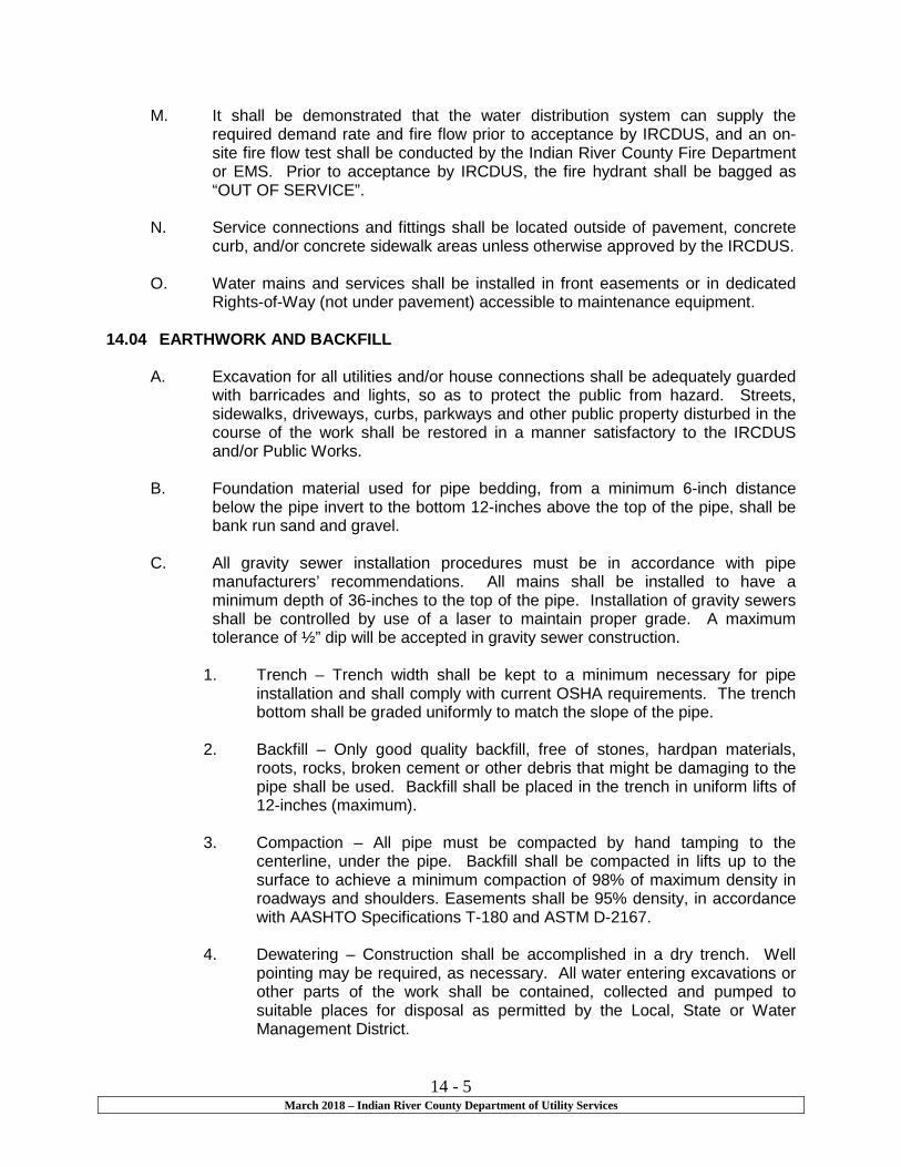
14 - 5 March 2018 – Indian River County Department of Utility Services
M. It shall be demonstrated that the water distribution system can supply the required demand rate and fire flow prior to acceptance by IRCDUS, and an on-site fire flow test shall be conducted by the Indian River County Fire Department or EMS. Prior to acceptance by IRCDUS, the fire hydrant shall be bagged as “OUT OF SERVICE”.
N. Service connections and fittings shall be located outside of pavement, concrete
curb, and/or concrete sidewalk areas unless otherwise approved by the IRCDUS.
O. Water mains and services shall be installed in front easements or in dedicated Rights-of-Way (not under pavement) accessible to maintenance equipment.
14.04 EARTHWORK AND BACKFILL
A. Excavation for all utilities and/or house connections shall be adequately guarded with barricades and lights, so as to protect the public from hazard. Streets, sidewalks, driveways, curbs, parkways and other public property disturbed in the course of the work shall be restored in a manner satisfactory to the IRCDUS and/or Public Works.
B. Foundation material used for pipe bedding, from a minimum 6-inch distance
below the pipe invert to the bottom 12-inches above the top of the pipe, shall be bank run sand and gravel.
C. All gravity sewer installation procedures must be in accordance with pipe
manufacturers’ recommendations. All mains shall be installed to have a minimum depth of 36-inches to the top of the pipe. Installation of gravity sewers shall be controlled by use of a laser to maintain proper grade. A maximum tolerance of ½” dip will be accepted in gravity sewer construction.
1. Trench – Trench width shall be kept to a minimum necessary for pipe
installation and shall comply with current OSHA requirements. The trench bottom shall be graded uniformly to match the slope of the pipe.
2. Backfill – Only good quality backfill, free of stones, hardpan materials,
roots, rocks, broken cement or other debris that might be damaging to the pipe shall be used. Backfill shall be placed in the trench in uniform lifts of 12-inches (maximum).
3. Compaction – All pipe must be compacted by hand tamping to the
centerline, under the pipe. Backfill shall be compacted in lifts up to the surface to achieve a minimum compaction of 98% of maximum density in roadways and shoulders. Easements shall be 95% density, in accordance with AASHTO Specifications T-180 and ASTM D-2167.
4. Dewatering – Construction shall be accomplished in a dry trench. Well
pointing may be required, as necessary. All water entering excavations or other parts of the work shall be contained, collected and pumped to suitable places for disposal as permitted by the Local, State or Water Management District.

14 - 6 March 2018 – Indian River County Department of Utility Services
5. Sheeting – Sheeting and shoring shall be installed as may be necessary for the protection of the work, preservation of adjacent property and structures and the safety of employees. Sheeting and bracing shall be uniform to OSHA requirements.
D. Installation of force mains (sewer or reused water) shall be in accordance with
latest AWWA Standard Specifications C-600 and the installation specifications for water lines in the Water Distribution Section, irrespective of the type of pipe selected. Location tape shall be placed continuously in the trench over all pipes, 12-inches below grade. Trace wire shall be wrapped on all pipes, valves, fittings, and all appurtenances, per Detail M-13.
1. Trench – Trench width shall be kept to a minimum necessary for pipe
installation and shall comply with current OSHA requirements. The trench bottom shall be graded and alignment shall be parallel with roadway, where possible.
2. Backfill – Only good quality backfill, free of stones, roots, rocks, broken
cement or other material that might be damaging to the pipe shall be used. Backfill shall be placed in the trench in uniform lifts of 12-inches (maximum).
3. Compaction – All pipe must be compacted by hand tamping to the
centerline, under the pipe. Backfill shall be compacted in lifts up to the surface to achieve a minimum compaction of 98% of maximum density in roadways and shoulders. Easements shall be 95% density, in accordance with AASHTO Specifications T-180 and ASTM D-2167.
4. Dewatering – Construction shall be accomplished in a dry trench. Well
pointing may be required, as necessary. All water entering excavations or other parts of the work shall be contained, collected and pumped to suitable places for disposal as permitted by the Local, State or Water Management District.
5. Sheeting – Sheeting and shoring shall be installed as may be necessary
for the protection of the work, preservation of adjacent property and structures and the safety of employees. Sheeting and bracing shall be uniform to OSHA requirements.
E. Installation of water mains and brine mains must be in accordance with latest
AWWA Standard Specifications C-600 Series, irrespective of the type of pipe selected. All installation procedures must also be in conformance with pipe manufacturers’ recommendations. Minimum depth of cover shall be 36-inches over the top of the pipe. Location tape shall be placed continuously in the trench over all pipes, 12-inches below grade. Trace wire shall be wrapped on all pipes, valves, fittings, and all appurtenances, per Detail M-13. Allowable deflection of the pipe joints and curvature of PVC pipe shall not exceed the manufacturers’ specifications.
1. Trench – Trench width shall be kept to a minimum necessary for pipe
installation and shall comply with current OSHA requirements. The trench

14 - 7 March 2018 – Indian River County Department of Utility Services
bottom shall be graded and alignment shall be parallel with roadway, where possible.
2. Backfill – Only good quality backfill, free of stones, roots, rocks, broken
cement or other material that might be damaging to the pipe shall be used. Backfill shall be placed in the trench in uniform lifts of 12-inches (maximum).
3. Compaction – All pipe must be compacted by hand tamping to the
centerline, under the pipe. Backfill shall be compacted in lifts up to the surface to achieve a minimum compaction of 98% of maximum density in roadways and shoulders. Easements shall be 95% density, in accordance with AASHTO Specifications T-180 and ASTM D-2167.
4. Dewatering – Construction shall be accomplished in a dry trench. Well
pointing may be required, as necessary. All water entering excavations or other parts of the work shall be contained, collected and pumped to suitable places for disposal as permitted by the Local, State or Water Management District.
5. Sheeting – Sheeting and shoring shall be installed as may be necessary
for the protection of the work, preservation of adjacent property and structures and the safety of employees. Sheeting and bracing shall be uniform to OSHA requirements.
14.05 RESTRAINED JOINTS
A. Restrained joints shall be used on lines per the Table of the IRCDUS Standards Drawing M-3. Section of piping having restrained joints or those requiring restrained joints shall be constructed using pipe and fittings with restrained “locked-type” joints and the joints shall be capable of holding against withdrawal for line pressures up to 150 pounds per square inch (psi). The pipe fittings shall be as shown for restrained push-on joints or restrained mechanical joints on Page 416 in Section VI, in the Handbook of Cast Iron Pipe, 4th Edition. In all cases, restrained joints must be used per Section C below, with thrust blocks, per contract drawings.
B. Restrained pipe joints that achieve restraint by incorporating cutout sections
installed in the bell of the pipe shall have a minimum wall thickness at the point of cutout that corresponds with the minimum specified wall thickness for the rest of the pipe.
C. The minimum number of restrained joints required for resisting forces at fittings
and changes in direction of pipe shall be determined from the length of restrained pipe on each side of fittings and changes in direction necessary to develop adequate resisting friction with the soil. Drawing and formula below are provided for the Contractor as a guideline.
Where:
L = 1.5PA(1-COS X)

14 - 8 March 2018 – Indian River County Department of Utility Services
Fw
L = Length of pipe on each side of fittings or change in direction
P = 150 psi, unless otherwise noted
A = Cross-sectional area in square inches based on outside diameter (O.D.) of pipe
X = Angle of bend or change in direction in degrees
f = Coefficient of friction = 0.4 (maximum)
W = W (earth) + W (pipe) + W (water in pipe) W (earth) = unit weight of soil in pounds = (density of soil*) (depth of cover in feet) (O.D. in feet) W (pipe) = unit weight of pipe in pounds W (water in pipe) = unit weight of water in pipe * Maximum 12-lbs/cubic ft above maximum water table elevation and 60-lbs/cubic ft below maximum water table
D. Bolts and nuts for restrained joints shall be 304 stainless steel.
E. The Contractor shall also provide restrained joints in accordance with the above
criteria wherever below ground fittings are on lines 12-inches in diameter or less. 14.06 HORIZONTAL SEPARATION
A. All water, reclaimed water and/or sewer utilities shall be located a minimum horizontal separation equal to the depth of the pipe plus the diameter of the pipe from any permanent above ground structures (i.e., walls, trees, transformer pads, etc.).
B. A minimum 4-feet separation is required between water/sewer utilities and other
underground utilities such as telephone, gas, cable, irrigation, etc.
C. All water and/or sewer utilities shall be located a minimum horizontal separation equal to 2 times the depth of the pipe plus the diameter of the pipe from the top of bank of any bodies of water (I.e., storm water ponds, canals, etc.).
D. All water mains shall be located a minimum horizontal separation of 3 ft. from
storm sewer, stormwater force main or reclaimed water main.
E. All water mains shall be located a minimum horizontal separation of 3 ft., with 10 ft. preferred, from vacuum sanitary sewer mains.
F. All water mains shall be located a minimum horizontal separation of 6 ft., with 10
ft. preferred, from gravity or pressure sanitary sewer, sanitary sewer force main or reclaimed water main.

14 - 9 March 2018 – Indian River County Department of Utility Services
14.07 VERTICAL SEPARATION
A. Maintain 18” vertical clearance between any water/sewer utility and any other underground utilities such as telephone, gas, cable, irrigation, etc.
B. All water mains shall maintain a minimum 6” vertical clearance between storm
sewer, vacuum sewer system and gravity sewer with 12” vertical clearance preferred. A 12” vertical clearance shall be maintained between all water mains and pressure sewer systems, stormwater force mains and reclaimed water mains.
END OF SECTION

Section 15
Procedures for Submittal, Permitting, Construction and Acceptance of Private Development Projects
15-1 March 2018 – Indian River County Department of Utility Services
Section 15
Procedures for Submittal, Permitting, Construction and Acceptance of Private Development Projects
15.01 Submittal
A. The applicant shall submit the following items for a project to be considered for a utility construction permit: 1. Completed Utility Construction Permit application, copy of Department
of Environmental Protection (FDEP) permit applications (if applicable), copy of Department of Transportation (FDOT) permit application (if applicable), Indian River County Right-of-Way permit, legal description, and proof of payment of all applicable fees.
2. Three sets of 24 inch x 36 inch construction plans, signed and sealed by a Professional Engineer registered in the State of Florida, shall be submitted with application. Plans shall include a plan view of the water, wastewater, and/or reclaimed systems with all elevations and inverts, sewer profiles (gravity and force mains), all appropriate details, the location of all existing and/or proposed drainage facilities including catch basins, manholes, pipes, and top elevations and pipe inverts for same, and water line profiles where the water main crosses other utilities. All IRCDUS utility lines shall be stationed on the plans. All existing and proposed rights-of-ways, easements, and property lines shall be shown. Also, an accurate location map is to be provided. The limits of proposed dedication of the system(s) to IRCDUS shall be specified on the plans.
3. A complete engineer’s design report, signed and sealed by a
Professional Engineer registered in the State of Florida, setting forth the basis of design, shall contain the following, as a minimum:
a. Water distribution system:
(1) Description of geographic area to be served. (2) Existing and predicted population of areas to be
served. (3) The effect of the proposed water distribution system on
existing or proposed water distribution facilities. (4) The estimated daily flow. (5) Fire flow calculations for all hydrants being fed by lines
smaller than 8 inch, or as required by IRCDUS. (6) Description of materials to be used. (7) A preliminary cost estimate. (8) An estimated completion date. (9) Any other factors which would affect design and use of
the water distribution system.

15-2 March 2018 – Indian River County Department of Utility Services
b. Gravity sewer system: (1) Description of geographic area to be served. (2) Existing and predicted population of areas to be
served. (3) The effect of the proposed gravity sewer collection
system on existing and proposed gravity sewer collection systems or pumping stations and force mains. Pump stations shall be modeled, and all in-line pumping stations and force mains receiving these additional flows shall be considered.
c. The effect of the proposed gravity sewer collection system on
the wastewater treatment plant receiving the flows. (1) The estimated daily flow. (2) Description of materials to be used. (3) A preliminary cost estimate. (4) Any other factors which would affect design and use of
the sewer system.
d. Pumping station and force main system: (1) Description of geographical area to be served. (2) Existing and predicted population of area to be served. (3) Calculations for projected flows, wet well sizing, pump
sizing and selection, force main sizing, and buoyancy of wet well.
(4) The effect of the proposed pumping station and force main system on existing or proposed pumping station and force main systems or gravity sewer systems receiving these additional flows. Pump stations shall be hydraulically modeled, along with all in-line pumping stations and force mains.
(5) The effects of the proposed pumping station and force main systems on the wastewater treatment plant receiving these flows.
(6) Description of materials to be used. (7) A preliminary cost estimate. (8) The estimated completion date (9) Any other factor which would affect design and use of
the pumping station and force main system.
4. A review fee, as set forth in the current rate schedule.
5. One original signed and sealed Department of Environmental Protection permit application for IRCDUS records.
15.02 Construction Permit
A. Prior to permit issuance and scheduling of a pre-construction meeting, three sets of construction plans and specifications shall be submitted, signed and sealed by a Professional Engineer registered in the State of Florida, to be approved, stamped, and signed by IRCDUS. One set shall be retained for

15-3 March 2018 – Indian River County Department of Utility Services
IRCDUS records, one set shall be delivered to the IRCDUS inspector, and one set shall be returned to the Engineer of Record.
B. Utility Construction Permits expire one year from the date of issuance and may be granted an extension for one year thereafter for a fee of $150. Only one extension will be granted. After the extension has expired, the Utility Construction Permit process will start over. IRCDUS reserves the right to request changes or modifications to utility designs that have been previously approved.
C. Payment of fees shall not constitute automatic approval of original plans. D. The Utility Construction Permit does not constitute a permit for operation.
E. Construction shall not begin until the IRCDUS Utility Construction Permit is
approved, and a copy of the Indian River County Right-of-Way Permit, Florida Department of Environmental Protection Permit, and any other required permits are submitted to IRCDUS.
15.03 Construction
A. Any contractor or sub-contractor constructing public underground water, sewer, and reclaimed utilities must be a licensed Underground Utility Contractor or licensed General Contractor in the State of Florida and Indian River County. A sub-contractor shall not qualify for an IRCDUS construction contract under the license of another General Contractor or Underground Utility Contractor. Any contractor or sub-contractor must qualify on their own merits.
B. IRCDUS reserves the right to request references and a list of projects
performed in the last three years that are similar in nature to the project in which the contractor is proposing to construct.
C. The Engineer of Record shall have a pre-construction meeting with IRCDUS
a minimum of five working days before beginning construction, whereupon construction plans shall be reviewed, and a minimum of three sets of shop drawings shall be provided. One set is to be provided to Indian River County Utilities Department, one set to the IRCDUS inspector and the remaining set to the Engineer of Record. No appurtenances shall be installed until approved by IRCDUS.
D. The Contractor and Engineer of Record shall notify IRCDUS a minimum of 48 hours prior to beginning construction or performing any system tests.
E. The water distribution system shall be constructed, flushed, disinfected, and tested in accordance with FDEP and IRCDUS Specifications.
F. All fire hydrant assemblies shall be bagged and tagged as “Out of Service”
until final acceptance.
15-4 March 2018 – Indian River County Department of Utility Services
G. All equipment, materials, and workmanship shall meet or exceed all current Indian River County Water, Wastewater and Reclaimed Water Utility Construction Standards and shall be subject to the unconditional inspection and approval by IRCDUS.
H. The Engineer of Record shall have an on-site inspector who shall witness and document all materials used, installation procedures, problems encountered, and witness and certify all tests specified by the operation permit checklists. Daily construction reports shall be submitted monthly to IRCDUS, and no later than seven days after completion of the construction. Indian River County has unconditional rights to inspect the construction and materials at any time.
I. Where water outages will occur, a minimum of five (5) working days notice to
IRCDUS and the public is required. The IRCDUS water plant operator shall be notified a minimum of five (5) working days prior to flushing of lines. Five (5) working days’ notice is required for access to private property.
J. The Property Owner, Developer, Engineer of Record, and Contractor shall hold Indian River County harmless in any suits, claims, and/or liabilities arising from subject construction.
K. All connections to the IRCDUS water system shall be made in the presence of IRCDUS. For the purpose of flushing, testing, and putting the system on line, IRCDUS shall operate all valves on the IRCDUS systems.
15.04 Acceptance
A. No system shall be cleared for use by IRCDUS until all requirements of the operation permit checklist have been satisfied and approved by IRCDUS. See Part IV of these Standards for the requirements for IRCDUS Utility Construction Check Lists for Potable Water Distribution System and Wastewater Collection/Distribution System.
B. When a constructed potable water system or sewer system lies dormant for a
period of more than six months, regardless of having received FDEP clearance or not, the system will be subjected to rigorous inspection, testing and cleaning, by methods to be determined by IRCDUS and in accordance with AWWA Standards C-651-99 or latest revision. Pressure testing, flushing and chlorination will be required. No potable water main shall be placed into service until bacteriological sampling and analysis have been made. Any constructed gravity sanitary sewer main and/or sewer lift station will be subject to the same methods as stated above, including but not limited to cleaning, television inspection, infiltration/exfiltration, or other methods to be determined by IRCDUS. Any deficiencies in construction shall be corrected immediately upon discovery and shall meet current IRCDUS Water and Wastewater Standards.
END OF SECTION
Section 16
Water and Wastewater Treatment Plants

16-1 March 2018 – Indian River County Department of Utility Services
Section16
Water and Wastewater Treatment Plants 16.01 General
This section sets forth the general requirements for design and installation of water and wastewater treatment plants to be constructed within Indian River County, hereinafter referred to as the “County”.
16.02 Design Standards
Facilities shall comply with the design and installation requirements as established by the Florida Department of Environmental Protection and additional specific requirements stated in these standards. The criteria set forth in the “Ten State Standards-Recommended Standards for Water Works”, latest edition, should be used as a design guide for water treatment facilities. The criteria set forth in the “Ten State Standards-Recommended Standards for Wastewater Facilities”, latest edition, shall be used as a design guide for sewage treatment facilities.
16.03 Standard Requirements
A. Building and Structure Sites
1. Clear and remove obstructions within building sites only as necessary to provide adequate workspace and/or facilitate the specified construction. The removal of trees or permanent structures within the specified construction areas shall be done only as approved or directed by the County. Should the removal of valuable trees or shrubs be required, this work shall be done in cooperation with the local communities in which the work takes place in order that they may be replanted, if so desired.
2. Grubbing shall be performed where required, including, but not
limited to, areas where fill will be placed, structures erected, or where other installation is required. It shall include the complete removal of all obstructions resting on or protruding through the surface of the existing ground to a depth of three feet below finished grade. Where excavation is done, all stumps, roots and deleterious material thereby exposed shall be removed to a depth of three feet minimum below the excavated surface.
3. All refuse from clearing and grubbing operations shall be disposed
of either by burning or removal to a dump area approved by the County. Burning shall be done at locations, and at times as directed, in a manner that will avoid all hazards. Permits shall be obtained from all applicable authorities for burning and burning shall be kept under constant attendance until the fires have burned out or have been extinguished. Burning operations shall be done in compliance with all applicable regulations.

16-2 March 2018 – Indian River County Department of Utility Services
4. All muck or other unsuitable material within the limits of building
sites, or other designated areas, shall be excavated and removed. Depth of removal shall be that required to reach an approved suitable material. Removal and subsequent backfilling shall be maintained within the limits of the designated construction area unless specifically approved otherwise by the County. Sheeting shall be installed and left in place along the site boundary, where required, in order to preclude infringement on adjacent property and prevent damage by future de-mucking. The Contractor shall dispose of muck or other unsuitable material.
5. Suitable fill material shall be placed and compacted where muck
or other unsuitable material has been removed and as required to elevate the site to finished grade. Fill material shall conform to the Florida Department of Transportation and as approved by a testing laboratory and the Indian River County Public Works Division. Fill shall be placed in successive layers of not more than 12 inches, loose measure, and suitably compacted to 95% minimum of maximum density, as determined by AASHTO Specifications T-180, unless higher percentage is necessary in specific locations, especially under structure sites where a minimum of 98% of maximum density is required. Side slopes shall not exceed 3 horizontal to 1 vertical, unless otherwise approved by IRCDUS, and shall be protected from erosion by staggered solid grass sodding, or other approved method. An approved, Florida State Certified testing laboratory shall make density tests for determination of the specified compaction.
6. All building sites shall be properly graded, including all cutting and
filling necessary for the construction. Finish building site elevations shall be as required to preclude flooding and shall receive prior approval from IRCDUS. Filling shall be accomplished, if necessary, to provide acceptable site elevations. Finish surface grades shall eliminate potholes, abrupt changes in grade and bring the ground to an even surface, and shall provide adequate drainage for the complete site. The grade shall be sloped evenly to provide drainage away from the building walls in all directions at ¼ inch per foot minimum (2%) for at least 10 feet from the building walls. Drainage swales shall have a minimum flow-line grade of not less than 1/8 inch per foot (1%). Rounding shall be provided at top and bottom of banks and at other breaks in grade.
7. Driveways, parking locations and other vehicular traffic areas at
building sites shall be paved with an asphaltic concrete surface course of a 1 inch minimum thickness, Type II, having a prime coat of RC-70 or RC-250 (rapid curing cutback asphalt) applied at a rate of 0.10 gallons per square yard. The dimensions for said surfacing shall be in accordance with good engineering practice and suitable for the designated service. Roadbed stabilization

16-3 March 2018 – Indian River County Department of Utility Services
shall be 6 inch minimum below the base course and shall have a minimum Limerock Bearing Ratio of 100 pounds per square inch. Base course shall be limerock or soil-cement, placed to 6-inch minimum thickness.
8. In order to provide an all-weather surface for foot traffic ways,
concrete walks shall be provided between points of frequent travel. Walks shall be minimum 4 feet wide by 4 inches thick. The base material shall be thoroughly compacted to 95% of maximum density per AASHTO Specification T-180. Walks shall be provided with expansion joints at structures and/or intervals not exceeding 18 feet, with dummy groove joints at 6-feet intervals. A broom finish shall be provided. Concrete shall be a minimum compressive strength of 2500 psi with fiber mesh reinforcement.
9. Fencing
a. All building sites shall be totally enclosed by protective fencing,
unless specifically excluded from this requirement by the County. Said fence shall consist of 6 feet high chain link fabric. Fence shall be fabricated and installed in accordance with good standard practices and shall be complete, including top rail; stretcher bars and clips; all end, corner, pull and gate posts; post braces; ornamental post tops; and other necessary items. All fencing materials shall be hot dipped galvanized as specified below in 9b. The fence shall include a minimal of one gate opening 12 feet in width, consisting of two 6 feet wide locking, 180 degree, swing gates, with total height equal to the fence.
b. Fencing shall be fabricated in compliance with the following
minimum material standards:
Chain Link Fabric – 2” mesh woven from 9 gage steel wire.
End, Corner and Pull posts – 2-½” Schedule 40 steel pipe.
Gate Posts – 6” maximum width: 2-½” Schedule 40 steel pipe; and, 6’ to 12’ width; 3-½” Schedule 40 steel pipe.
Gate Frames and Intermediate Posts – 1.875” outside diameter (O.D.), 2.71 pounds per foot (Lb./Ft.) steel tube.
Post Braces and Top Rails – 1.625” O.D., 2.27 Lb./Ft. steel tube.
Accessories – Steel.
Coatings – Hot dip galvanized with 1.2 ounces of zinc per square foot, applied after weaving for fabric and following fabrication for all other ferrous metal items.
16-4 March 2018 – Indian River County Department of Utility Services
Concrete – 2,500 pounds per square inch compressive strength.
c. The fencing shall be installed to proper grade, alignment and
plumb, with corner posts and bracing provided at all angles in alignment. Posts shall be set 2 feet deep in concrete footings: 1 foot 4 inches in diameter for line posts and 2 feet in diameter for gate and corner posts.
10. Landscaping and Grassing
a. Building sites shall be suitably landscaped in order to be
harmonious with the existing or projected adjacent development, provide screening plants and, in general, present a pleasing appearance. Plants shall equal or exceed Standards for Florida No. 1, as given in “Grades and Standards for Nursery Plants,” Part I (1963) and Part II, State of Florida Department of Agriculture. The landscaper shall install the approved planting (grass, trees and shrubbery) in accordance with Indian River County Code Type A buffer and maintain said items until hardy growth has been established.
1 The Contractor shall provide IRCDUS with landscaping
plans for approval prior to installation. Said plan shall be prepared by an experienced landscaping company and shall include only such plants which are established for the area of construction and which require minimal maintenance.
2 The Contractor shall place solid sod, where not
covered by structures or surfacing, over the total area of small facility sites (pumping stations, etc.) and over the prime area of large sites (Treatment Facilities), with additional placement, as required for erosion control. Where not solid-sodded, balance of the site area shall be totally grassed by plugging. Unless approved otherwise by the IRCDUS, the grass shall be Argentine Bahia. Sod and plugs shall be fresh and uninjured to time of installation, and sod shall be clean, have a well-matted root system, and have a minimum thickness of 2 inches.
11. Buildings and Structures
a. Excavation shall not proceed until building lines have been
surveyed and staked. The Contractor shall remove and dispose of all unwanted material, supply all fill material, and install all dewatering facilities, shoring and/or bracing needed.

16-5 March 2018 – Indian River County Department of Utility Services
Bearing capacity of surfaces in excavations or on compacted fill shall be adequate to support the building or structure to be placed thereon. IRCDUS shall require testing by an independent testing laboratory to verify adequacy of the foundation design and/or to require special foundation features, such as larger footings, piles, increased compactions, etc.
Fill and backfill shall be compacted to a minimum of 98% of maximum density at optimum moisture, as determined by ASTM D-1557, Method D, or AASHTO Specification Method T-180.
Building site shall be kept clear of rubble and any material, which may be hazardous to persons or impede construction progress.
b. When structures are to be constructed of, or are to contain,
any wood or wood products, soil treatment shall be required for termite control.
Chemicals shall be one of the following water-based emulsions, uniform in composition, containing a dye that will be readily seen to the naked eye after application to the soil, and containing in concentration by weight:
1 Dieldrin, 0.5 percent 2 Aldrin, 0.5 percent 3 Heptochlor, 0.5 percent 4 Or equal
Application of chemical selected shall be made to all areas along foundation walls, around piers and under all concrete slabs at the following rates:
5 Foundation walls and piers, all sides, 4 gallons per 10
linear feet, mixed with backfill, to a depth of one foot below finished grade for concrete; for masonry, increase application rate proportionately by depth of foundation or piers.
6 Within voids of masonry foundation walls or piers, apply to void at or near bottom of foundation at rate of 2 gallons for each 10 linear feet.
7 Under all concrete slabs less than 6 feet below finish grade, one gallon per 10 square feet.
c. Design, material, workmanship and practices shall conform to
American Concrete Institute Manual of Standard Practice (ACI 315) and the Code of Standard Practice of the Concrete Reinforcing Steel Institute (CRSI).

16-6 March 2018 – Indian River County Department of Utility Services
Field and laboratory tests shall be conducted by independent testing laboratory on structural concrete pours for buildings to ascertain that concrete design slumps and strengths are attained.
Applicable standards shall include latest editions of the following:
1 Southern Standard Building Code 2 Building Code Requirements for Reinforced Concrete –
ACI 318 3 Concrete proportions and placing – ACI 211.1 and ACI
301 4 Concrete design for sanitary engineering structures –
ACI Committee 350 Report 68-50 5 Formwork – ACI 347 6 Reinforcing bars – ASTM A-615, Grade 60 7 Stirrups and ties – ASTM A-615, Grade 40 8 Welded wire fabric – ASTM A-185 9 Cement for concrete not exposed to sewage – ASTM
C-150, Type I 10 Cement for concrete exposed to sewage – ASTM C-
150, Type II, or ASTM C-150, Type I, with sulfate resistant properties equal to Type II if Type II is not available and the design engineer affirms the acceptability of Type I
11 Watertight and chemical resistant concrete – ACI 614 12 Aggregate – ASTM C-33, salt free 13 Water – potable (free from oil, alkali, acid, salt, organic
matter, etc.) 14 Ready-mix – ASTM C-94 15 Slump test – ASTM C-143 16 Compression Test – ASTM C-39, at cylinder ages of 7
days, 28 days and finally, if indicated and directed by design engineer, at extended time period, not to exceed 45 days
17 Test Cylinders-ASTM C-31 minimum of 3 per 50 cubic yard of pour or fraction thereof.
Water stops and vapor barriers shall be provided as follows:
18 Water stops shall be installed at all construction joints
in concrete structures retaining liquid and at all construction joints at or below ground level in concrete structures required to remain dry.
19 Damp check or waterproof membranes shall be installed under and around all concrete slabs to be placed against soil, with joints lapped a minimum of 6 inches.
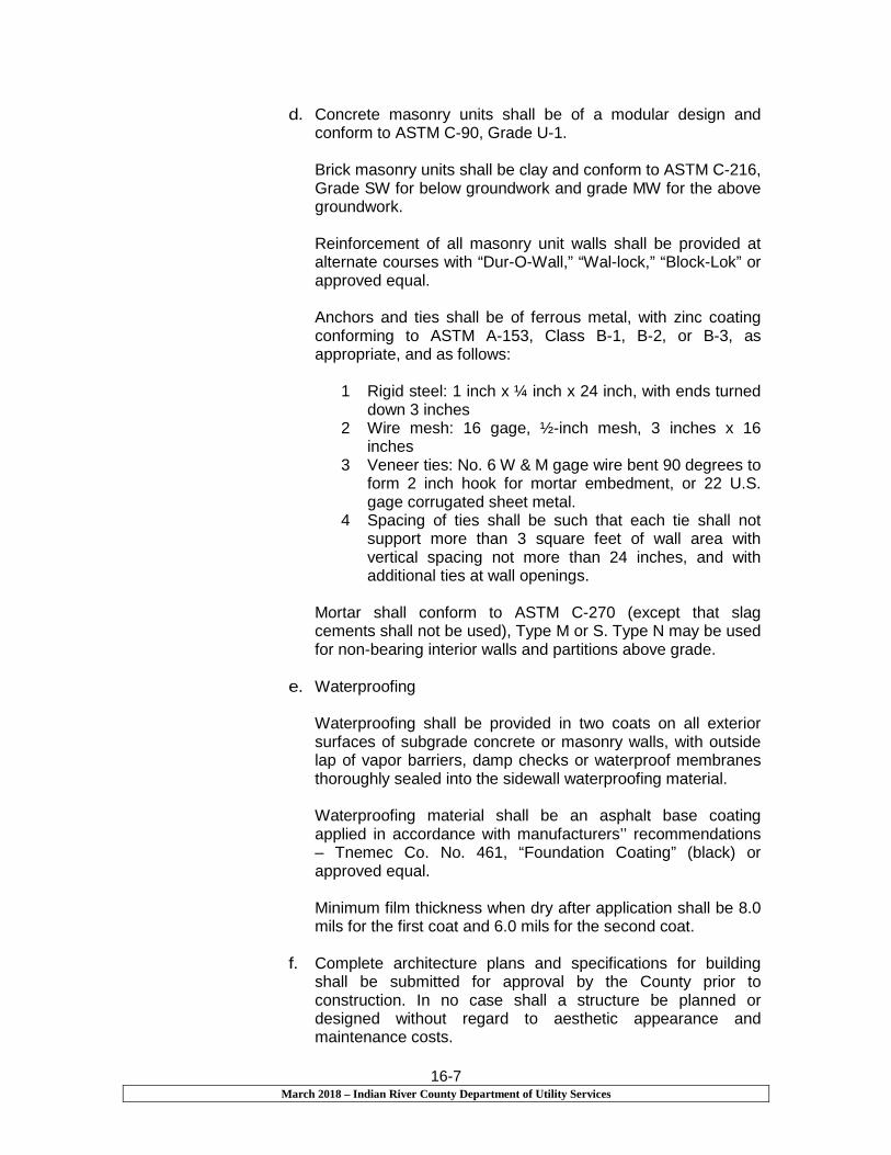
16-7 March 2018 – Indian River County Department of Utility Services
d. Concrete masonry units shall be of a modular design and conform to ASTM C-90, Grade U-1.
Brick masonry units shall be clay and conform to ASTM C-216, Grade SW for below groundwork and grade MW for the above groundwork.
Reinforcement of all masonry unit walls shall be provided at alternate courses with “Dur-O-Wall,” “Wal-lock,” “Block-Lok” or approved equal.
Anchors and ties shall be of ferrous metal, with zinc coating conforming to ASTM A-153, Class B-1, B-2, or B-3, as appropriate, and as follows:
1 Rigid steel: 1 inch x ¼ inch x 24 inch, with ends turned
down 3 inches 2 Wire mesh: 16 gage, ½-inch mesh, 3 inches x 16
inches 3 Veneer ties: No. 6 W & M gage wire bent 90 degrees to
form 2 inch hook for mortar embedment, or 22 U.S. gage corrugated sheet metal.
4 Spacing of ties shall be such that each tie shall not support more than 3 square feet of wall area with vertical spacing not more than 24 inches, and with additional ties at wall openings.
Mortar shall conform to ASTM C-270 (except that slag cements shall not be used), Type M or S. Type N may be used for non-bearing interior walls and partitions above grade.
e. Waterproofing
Waterproofing shall be provided in two coats on all exterior surfaces of subgrade concrete or masonry walls, with outside lap of vapor barriers, damp checks or waterproof membranes thoroughly sealed into the sidewall waterproofing material.
Waterproofing material shall be an asphalt base coating applied in accordance with manufacturers’’ recommendations – Tnemec Co. No. 461, “Foundation Coating” (black) or approved equal.
Minimum film thickness when dry after application shall be 8.0 mils for the first coat and 6.0 mils for the second coat.
f. Complete architecture plans and specifications for building
shall be submitted for approval by the County prior to construction. In no case shall a structure be planned or designed without regard to aesthetic appearance and maintenance costs.

16-8 March 2018 – Indian River County Department of Utility Services
Exterior wall finishes for permanent above-grade buildings or structures shall comply with one or more of the following selection of materials:
1 Stucco/stucco brick 2 Rubbed concrete 3 Brick, over masonry or sturdy wood frame 4 Stone aggregate on masonry 5 Stone 6 Asbestos-cement on masonry substrate
g. Steel or other ferrous materials shall conform to the following:
1 Structural shapes and plates – ASTM A-36 2 Pipe – ASTM A-53 3 Bolts, machine – ASTM A-307 4 Bolts, high tensile – ASTM A-325 5 Galvanizing – ASTM A-123 or A-153, as applicable 6 Iron castings – ASTM A-48, Class 25 7 Abrasive cast iron (nosings) – American Abrasive
Metals Co. “Feralun,” or approved equal. 8 Cast steel – ASTM A-27, Grade N2 9 Stainless steel – Type 304, unless otherwise required
or specified 10 Fabrication and erection – AISC Manual of Steel
Construction.
Aluminum materials shall conform to the following: 11 Rolled shapes, smooth or checkered plates and
extruded pipe – ALCOA 6061-T6 or approved equal 12 Other extruded shapes – ALCOA 6063-T5 or approved
equal 13 Sheets -- ALCOA 3003 or approved equal 14 Pipe hand railing – ASTM B-429
h. Natural light is preferred for all buildings, and use of common
sizes, spaced for adequate natural lighting of interiors is encouraged.
Windows and frames shall conform to quality standards ANSI A-34 and AAMS 30 for high performance series.
Frames shall be basic aluminum 6063-T5 with fasteners of aluminum or stainless steel.
Plate glass shall be a minimum thickness of 7/32” and set in vinyl glazing material.

16-9 March 2018 – Indian River County Department of Utility Services
All windows shall be sealed all around, both sides, with a non-shrink silicone-base caulk.
i. Door frames shall be a combination buck and frame type, with
adjustable anchors for masonry applications. Frames shall be filled with sand-cement grout when installed.
Doors shall be constructed of honeycomb material with metal laminated facing. Minimum door thickness is 1 ¾”. Height is 6’–8”.
All doors and frames shall be mortised and reinforced to receive hardware. Non-ferrous metal should be used at all areas exposed to corrosive atmosphere.
All door frames shall be sealed all around, both sides, with a non-shrink silicone base caulk.
j. Finished Hardware shall be heavy duty type with non-magnetic
accessories and compatible with door and frame materials.
Panic exit devices shall be provided in all areas of corrosive or hazardous atmosphere that may be encountered by occupants.
Finished hardware shall include:
1 Locksets – cylinder type with dead latch, suitable for
master keying 2 Butt hinges – 1 ½ pairs per door, ball bearing type
preferred 3 Door closers, holders and silencers 4 Thresholds – aluminum 5 Flush bolts 6 Panic exit devices, as indicated
k. All carpentry components shall be of high quality, with
galvanized fasteners and treated wood where in contact with all masonry, metal or exposed to weather.
Rough Carpentry of construction grade lumber shall conform to standards as follows:
1 National Lumber Association – Specification for stress
grade lumber and its fasteners 2 American Institute of Timber Construction - Uniform
Specifications 3 Truss Plate Institute Specifications
Finish carpentry or millwork shall be of “B” or better yard grade seasoned lumber, conforming to applicable requirements of

16-10 March 2018 – Indian River County Department of Utility Services
the Architectural Woodwork Institute. Shelving, cabinet doors, tops and ends shall be a minimum of ¾” plywood with all exposed edges trimmed with hardwood. Joints shall be tight and formed to conceal shrinkage.
l. Moisture controls methods and materials for roofing shall be
similar to Johns-Manville or Bird Specifications or approved equal for built-up and shingle roofs.
Flat roofs shall have a minimum slope of 1/16 inch per foot, with 5 ply built-up roofing meeting the requirements for a 20 year bond. All built-up roofs on concrete slabs or metal decking shall be applied to 1 inch rigid insulation board.
Pitched shingle roofs shall have a minimum pitch of 3-½ inches vertical to 12 inch horizontal, with seal down type asphalt or fiberglass shingles at 300 lb. per square on two) layers of 15 pound underlayment, meeting requirements for a minimum of 15 year warranty. As an alternative to shingle roofs, metal roofs are acceptable upon approval by IRCDUS and the County Building Department.
Fascia, gravel stops and soffits shall be of low maintenance materials, architectural metal or masonry preferred.
Flashing and trim shall be either galvanized steel, 24 gage minimum thickness, conforming to Fed. Spec. QQ-S775, Type I, Class C; or aluminum 0.019” minimum thickness.
Gutters and downspouts shall be provided on all permanent buildings. Screen protection from debris and concrete splash blocks are required for all downspouts. Materials shall be as follows:
1 Gutters shall be 24 gage galvanized steel or 0.032”
anodized aluminum 2 Downspouts shall be 26 gage galvanized steel or
0.025” anodized aluminum 3 Hanger straps shall be the same material as gutters,
and 3 feet on centers, with blocking behind downspouts
m. Stairs shall be of reinforced concrete or all-welded structural
aluminum. Nosing and treads shall be non-skid. Tread widths and riser heights shall conform to applicable codes wherever possible. The use of ship-ladders or vertical ladders is discouraged.
Handrails shall be of all-welded 1 ½ inch outside diameter aluminum pipe, 42 inches high with intermediate rails. Rail
16-11 March 2018 – Indian River County Department of Utility Services
post spacing shall not exceed 8 feet. Kick plates shall be used on all areas above the first floor.
Grating and checkered plate shall be of aluminum, and designed to carry a uniform live load of 200 pounds per square foot with a safety factor of 5, based on ultimate strength. Reinforcing shall be utilized to preclude deflections greater than 1/160 of span. All grating and plates shall have non-skid surfaces.
Plumbing fixtures shall include, but not necessarily be limited to water closets and lavatories. IRCDUS may require shower, water heater and drinking fountain at larger facilities. Appropriate toilet partitions and stainless steel accessories shall be provided as indicated. Provide handicap facilities as required.
Fire extinguishers shall be 10 pound type ABC rechargeable units, provided and spaced as applicable in all buildings and structures.
Other safety equipment shall be provided wherever hazardous materials or equipment are utilized, such as eyewash fountains, gas masks, emergency lighting, etc.
16.04 Painting
A. General
This section includes the general requirements for painting materials and workmanship, as applicable to all sewer and water facilities.
Painting materials shall be delivered to the work site in the original and unbroken containers, marked with the manufacturer name, type of material and analysis of the product, and stored at one location. Special care shall be exercised in the handling and maintenance of painting materials, and all applicable safety regulations shall be followed.
Table 1 on page 16-14 shall be included in the project specifications for specific facility items and surfaces. Said schedule shall include, but not be limited to, the specific surface to be coated and specified painting system, with minimum dry mil thickness per coat required.
1. Materials
All paints and painting materials shall be high-grade products of manufacturers of established reputation and shall be "Approved" for the intended use.

16-12 March 2018 – Indian River County Department of Utility Services
To ensure a satisfactory end product, it is essential that paint coats be mutually compatible; both shop and field applications. To this end, insofar as possible, all paints applied to a given surface shall be the product of a single manufacturer.
The paint material set forth in Table 1 shall be the minimum acceptable type for the application indicated.
2. Application
The Contractor shall do a complete painting job throughout the project in accordance with generally approved modern practice for work of high quality. Additionally, surface preparation and application shall be in strict compliance with the manufacturers’’ recommendations, and paint shall not be extended or modified.
Factory finish coatings shall be inspected following installation and any mars or blemishes shall be touched up in the field with the original color and type of paint.
3. Painting Requirements
Table I, on page 16-14, specifies in general the surfaces to be painted; service conditions for the indicated surfaces; finish paint coating for the specific surface and service condition; and other special requirements. The total painting system (surface treatment, primer, finish coat and other necessary applications) and minimum dry mil thickness per coat required to achieve the specified finish for the specific surface and service condition shall be in strict compliance with the paint manufacturers’’ recommendations.
For convenience of description and as a standard for a quality comparative reference, Table 1 indicates the finish coating by name, number, or both, for products manufactured by Tnemec Company, Inc. or an approved equal, for the subject manufacturer, and approved equal products are acceptable.
In addition to the data contained herein, painting for water storage tanks shall comply with AWWA Standard Specifications D102-97, or latest revision, “Coatings for Steel Water Storage Tanks.”
Unless specifically indicated under “Pipe Color Code”, the color for surfaces to be painted shall be as selected by the IRCDUS and in compliance with OSHA regulation. The finish paint color for exposed sewerage and water facilities piping shall be as follows for the specified service:
Pipe Color Code: Sewage—Gray (Solid)

16-13 March 2018 – Indian River County Department of Utility Services
Sludge—Brown (Solid) Potable Water—Blue (Solid) Raw Water (water facilities)—Blue (with 2-inch bright orange bands spaced 24 inches apart) Reclaim-Pantone Purple Brine-Orange Non-Potable Water (Plant)—(Bright Orange (Solid) Gas or Fuel Oil—Red (Solid) Compressed Air—Green (Solid) Chlorine Gas—Yellow (Solid) Chlorine or other chemical solutions—Yellow (with 24 inch red bands spaced 24 inches apart) Other Services—As directed by the County Note: Banding shall be accomplished by painting or
approved durable plastic adhesive tape.
Surfaces which shall not require painting (unless service color coding, or other specific coatings are required), are as follows: exterior piping, below ground; factory finished equipment; galvanized fencing; stainless steel; aluminum and brass; plastic or rubber; concrete floors and stair treads; interior of concrete below grade dry pits; and exterior concrete surfaces.

16-14 March 2018 – Indian River County Department of Utility Services
Table 1
Paint Schedule
General Applications
Surface to be Painted Service Conditions Finish Paint Coating Masonry and Concrete, Walls Interior Above Grade Series 6 or 7 and Ceilings Normal Conditions
Masonry and Concrete, Exterior Above Grade Series 6 or Buildings and Tanks Normal Conditions Series 156/157 Wood Interior Ponkote 300 Enamel Normal Conditions Primer 36-601
Finish Series 66 Wood Exterior Finish Series 73 Normal Conditions Metal, Machinery, Piping, Interior, Primer 50-330 Systems, etc. Normal Conditions Finish Series 66 Non-submerged Metal, Machinery, Piping, Exterior, Primer 50-30 Systems, etc. Normal Conditions Finish Series 73 Metal, Machinery, Piping, Severe Moisture and Primer 50-30 Systems, etc. Condensation Finish Series 73 Metal, Large areas, Tank Exterior- Moderate to Primer 66-1211 Structural Steel, etc. Normal Conditions Finish Series 73
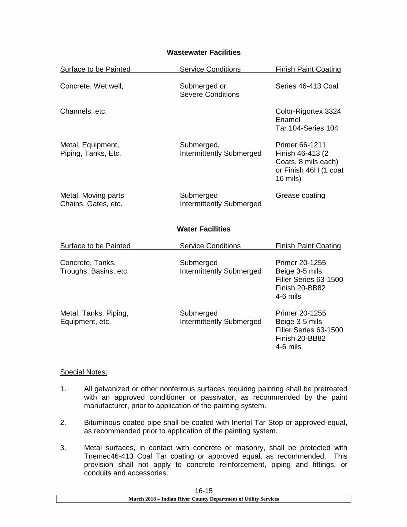
16-15 March 2018 – Indian River County Department of Utility Services
Wastewater Facilities
Surface to be Painted Service Conditions Finish Paint Coating
Concrete, Wet well, Submerged or Series 46-413 Coal Severe Conditions Channels, etc. Color-Rigortex 3324 Enamel Tar 104-Series 104 Metal, Equipment, Submerged, Primer 66-1211 Piping, Tanks, Etc. Intermittently Submerged Finish 46-413 (2 Coats, 8 mils each) or Finish 46H (1 coat 16 mils) Metal, Moving parts Submerged Grease coating Chains, Gates, etc. Intermittently Submerged
Water Facilities
Surface to be Painted Service Conditions Finish Paint Coating Concrete, Tanks, Submerged Primer 20-1255 Troughs, Basins, etc. Intermittently Submerged Beige 3-5 mils Filler Series 63-1500 Finish 20-BB82 4-6 mils Metal, Tanks, Piping, Submerged Primer 20-1255 Equipment, etc. Intermittently Submerged Beige 3-5 mils Filler Series 63-1500 Finish 20-BB82 4-6 mils Special Notes: 1. All galvanized or other nonferrous surfaces requiring painting shall be pretreated
with an approved conditioner or passivator, as recommended by the paint manufacturer, prior to application of the painting system.
2. Bituminous coated pipe shall be coated with Inertol Tar Stop or approved equal,
as recommended prior to application of the painting system. 3. Metal surfaces, in contact with concrete or masonry, shall be protected with
Tnemec46-413 Coal Tar coating or approved equal, as recommended. This provision shall not apply to concrete reinforcement, piping and fittings, or conduits and accessories.

16-16 March 2018 – Indian River County Department of Utility Services
16.05 Electric
A. General
The provisions of this Section, including other specific design considerations, shall be the minimum standards as applicable to all sewage and water facilities.
It shall be the responsibility of the Contractor to advise the Florida Power and Light Company or the City of Vero Beach regarding the proposed facility prior to installation and to make the necessary provisions for service thereto.
In accordance with the provisions of the General Conditions, complete shop drawings and technical data shall be submitted to IRCDUS including, but not limited to, motor control centers and control systems, with wiring diagrams and components; manufacturers’’ data for switches, transformers, relays, lighting fixtures and other accessories; panel boards; and all other applicable information.
B. Materials, Equipment and Installation
General Requirements: Materials, equipment and workmanship shall conform to the applicable portions of the codes, specifications, standards and statutes listed below:
National Fire Protection Association: NFPA No. 70 National Electrical Code
Local Codes: At the place of the work, all applicable local codes, regulations and ordinances that are in effect will apply. National Electrical Manufacturers Association: AB 1 Circuit Breakers – Molded Case FB 1 Conduit Fittings, Cable Fittings and Accessories IC 1 Industrial Control SGB 1 Connectors – Electric Power KS 1 Enclosed Switches PB 1 Panel boards TR 1 Transformers SG 8.2 Connectors for Copper Conductors IC 4 Industrial Enclosures WC 5 Thermoplastic – Insulated Wire & Cable American National Standards Institute: C80.1 Rigid Steel Conduit C6.1 Terminal Markings for Electrical Apparatus Underwriters’ Laboratories, Inc.

16-17 March 2018 – Indian River County Department of Utility Services
Standards for Cabinets and Boxes Standards for Service Equipment Standard for Industrial Control Equipment Standard for Thermoplastic-Insulated Wire
Illuminating Engineering Society:
IES Lighting Handbook United States Federal Government:
Williams–Steiger Occupational Safety and Health Act of 1970 (OSHA)
C. Special Requirements:
Phase rotation of electrical service shall be: L1, L2, L3 (A, B, C) left to right when facing equipment.
Generator receptacles for portable emergency power connection shall be provided for all electrically operated facilities and shall be as described in the lift station portion of the standards. (Refer to Section 10.10 “B1” and Section 10.10 “C2d” and Drawing S-18).
Motors shall have enclosure types which provide safe protection from exposure to unusual environments such as chemical fumes, damp places, outdoors, poorly ventilated rooms or places with restricted air circulation. In general, enclosures shall be NEMA standardized motor types.
Motor insulation materials shall be Class F Systems.
Motors for non-submersible service shall be sized such that the nameplate horsepower rating shall not be less than 1.2 times the required shaft brake horsepower output. Appropriate NEMA design shall be used to provide torque and/or other load requirements.
Motor electrical rating shall be compatible with station electrical service.
Motor mounts shall be of standard NEMA design and shall be compatible with the driven apparatus.
Motors shall be controlled by NEMA standard controllers for all across the line or reduced voltage starting. Where variable speed pumping is required, the specifications or variable speed pumping is required, the specifications or variable speed control equipment shall be coordinated with the County. In general, motors shall be equipped with all necessary controls and devices for complete and operable systems.
END OF SECTION

Section 17
Engine Driven Generator Sets

March 2018 - Indian River County Department of Utility Services
17-1
Section 17
Engine Driven Generator Sets
17.1.01 General
A. This specification defines the requirements for an emergency or
standby Electric Generator Set for wastewater pumping stations. The
generator set shall consist of a diesel or natural gas-powered engine
directly coupled to an electric generator, together with the necessary
controls and accessories to provide electric power for the duration of
any failure of the normal power supply.
Any and all local or state requirements for standby power systems not
covered by this specification will be the responsibility of the
Contractor, supplier and manufacturer to meet.
B. Housing developments of 200 or more units shall provide backup
generator sets for emergency use as required (Note #2 on Drawing
S-21). Generator shall be provided with automatic throw over
(transfer) switch that senses power interruption from the main power
source, starts the generator and shifts the power supply to the lift
station from the generator.
17.1.02 Design Standards
A. The equipment covered by these specifications shall be designed,
tested, rated, assembled and installed in strict accordance with all
applicable standards of ANSI, NEC, ISO, U.L., IEEE and NEMA.
B. The Contractor shall provide a complete integrated emergency
generator system. The system consists of a diesel generator set with
related component accessories and Automatic Transfer Switch(es) as
specified herein.
C. The generator set shall have the following characteristics:
Voltage 240/480 (As Required By Power Supply)
Phase 3
Connection Y
Wire 4
Hertz 60
Power Factor 0.8
The generator set shall be capable of starting and running the existing
loads and proposed loads without exceeding the maximum voltage and
frequency variations specified herein, or the maximum temperature
limitations of the engine and generator. The generator set shall be
capable of starting all motor loads, with the non-inductive load applied
first.
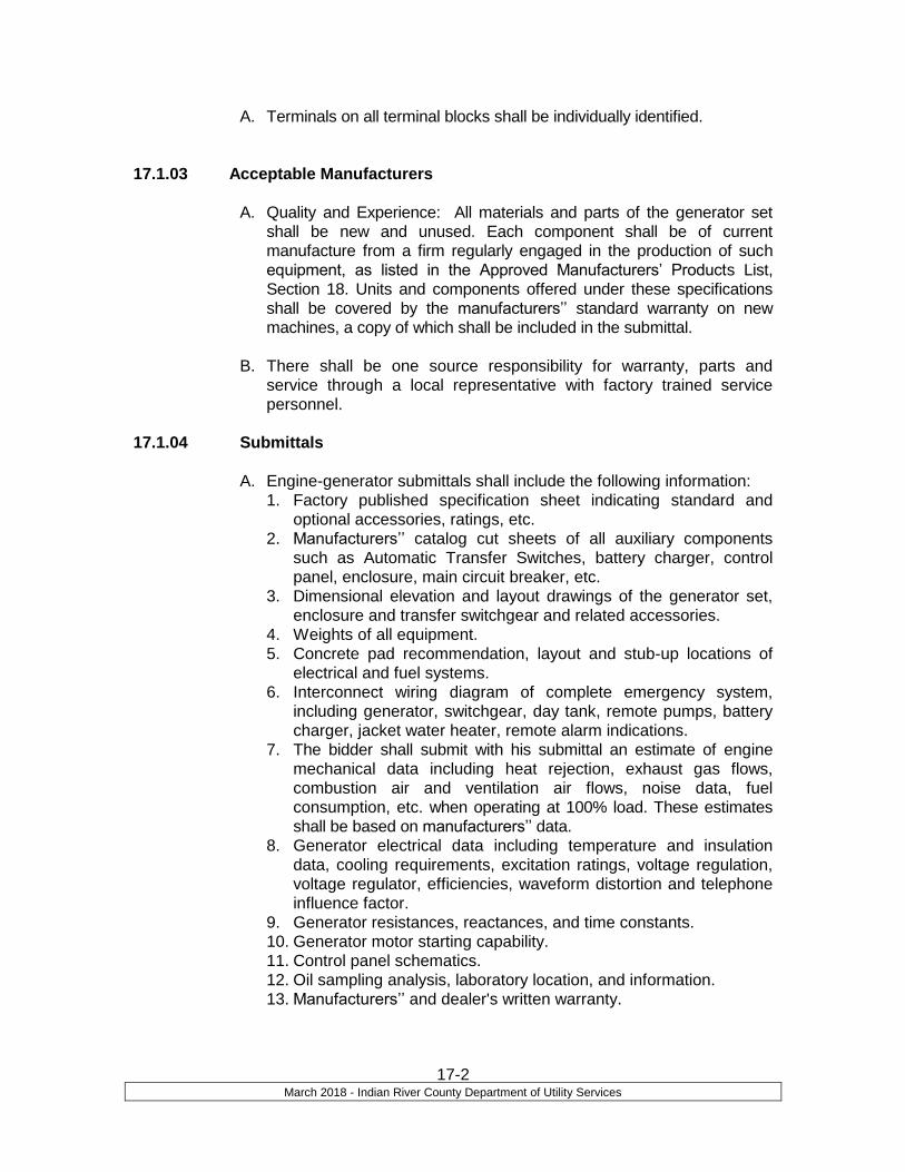
March 2018 - Indian River County Department of Utility Services
17-2
A. Terminals on all terminal blocks shall be individually identified.
17.1.03 Acceptable Manufacturers
A. Quality and Experience: All materials and parts of the generator set
shall be new and unused. Each component shall be of current
manufacture from a firm regularly engaged in the production of such
equipment, as listed in the Approved Manufacturers’ Products List,
Section 18. Units and components offered under these specifications
shall be covered by the manufacturers’’ standard warranty on new
machines, a copy of which shall be included in the submittal.
B. There shall be one source responsibility for warranty, parts and
service through a local representative with factory trained service
personnel.
17.1.04 Submittals
A. Engine-generator submittals shall include the following information:
1. Factory published specification sheet indicating standard and
optional accessories, ratings, etc.
2. Manufacturers’’ catalog cut sheets of all auxiliary components
such as Automatic Transfer Switches, battery charger, control
panel, enclosure, main circuit breaker, etc.
3. Dimensional elevation and layout drawings of the generator set,
enclosure and transfer switchgear and related accessories.
4. Weights of all equipment.
5. Concrete pad recommendation, layout and stub-up locations of
electrical and fuel systems.
6. Interconnect wiring diagram of complete emergency system,
including generator, switchgear, day tank, remote pumps, battery
charger, jacket water heater, remote alarm indications.
7. The bidder shall submit with his submittal an estimate of engine
mechanical data including heat rejection, exhaust gas flows,
combustion air and ventilation air flows, noise data, fuel
consumption, etc. when operating at 100% load. These estimates
shall be based on manufacturers’’ data.
8. Generator electrical data including temperature and insulation
data, cooling requirements, excitation ratings, voltage regulation,
voltage regulator, efficiencies, waveform distortion and telephone
influence factor.
9. Generator resistances, reactances, and time constants.
10. Generator motor starting capability.
11. Control panel schematics.
12. Oil sampling analysis, laboratory location, and information.
13. Manufacturers’’ and dealer's written warranty.

March 2018 - Indian River County Department of Utility Services
17-3
B. Operation and Maintenance Information. The system supplier shall
furnish five sets of operating, maintenance and parts manuals to
IRCDUS covering all components for the generator set system. The
supplier shall also instruct the Owner and/or IRCDUS in operation and
maintenance of the unit.
17.1.05 Warranty
A. The manufacturers’’ standard warranty shall in no event be for a period
of less than five (5) years from date of initial start-up of the system
and shall include repair parts, labor, reasonable travel expense
necessary for repairs at the job site, and expendables (lubricating oil,
filters, antifreeze, and other service items made unusable by the
defect) used during the course of repair. Submittals received without
written warranties as specified will be rejected in their entirety.
17.1.06 Parts and Service Qualifications
A. Engine driven generator sets which can be properly maintained and
serviced without causing IRCDUS either to carry expensive parts stock
or to be subjected to the inconvenience of long periods of interrupted
service because of lack of available parts. The supplier shall specify
the nearest location of permanent parts outlets from which parts may
be obtained.
B. The engine-generator supplier shall have service facilities within 75
miles of the project site and maintain 24-hour parts and service
capability. The distributor shall stock parts as needed to support the
generator set package for this specific project.
C. The dealer shall maintain qualified, factory trained service personnel
that can respond to an emergency call within 2 hours of notification,
24 hours per day.
PART 2 – PRODUCTS
17.2.01 GENERAL REQUIREMENTS
A. The equipment supplied and installed shall meet the requirements of
the NEC and all applicable local codes and regulations. All equipment
shall be of new and current production by a MANUFACTURER who
has 25 years of experience building this type of equipment. Units and
components offered under these specifications shall be covered by the
manufacturers’’ standard warranty on new machines, a copy of which
shall be included in the submittal. Manufacturer shall be ISO9001
certified.

March 2018 - Indian River County Department of Utility Services
17-4
B. The system shall be free of injurious torsional and bending vibrations
within a speed range from 10% below to 10% above synchronous
speed.
C. The system shall be adequately guarded both physically and electrically
for protection of operating personnel.
17.2.02 ENGINE
A. General Description. The engine shall be of the internal combustion
type equipped to operate on natural gas, at locations where natural gas
is available or No. 2 diesel fuel.
B. Engine Power Rating. The rated net horsepower of the engine at the
generator synchronous speed, with all accessories, shall not be less
than that required to produce the KW required. The horsepower rating
shall take into account generator efficiency and all parasitic losses such
as fan, battery charger, etc. The generator set shall be capable of
producing the required KW (without overload) for the duration of the
power outage (standby rating), under the following ambient conditions:
Altitude, feet 1000
Ambient temperature range, oF 0-100
Humidity at max. ambient temp. % 80
C. Fuel and Oil Consumption. Accompanying the supplier's bid, the bidder
shall supply fuel and oil consumption estimates based on engine
manufacturers’’ data, a copy of which shall be included in the submittal.
D. Governor (Engine Speed Control). The engine shall be equipped with
a suitable governor to maintain frequency within limits, as specified
below, by controlling engine and generator speed.
1. Type: isochronous
2. Stability: 1/4% maximum steady state frequency variation at any
constant load from no load to full load.
3. Regulation: 1/4% maximum frequency deviation between
no-load steady state and full-load steady state.
4. Transient: 5% maximum frequency dip on most severe motor
starting condition.
5. Transient: 2 seconds maximum recovery time for maximum
motor start.
6. The manual speed adjusting control shall be mechanical or
electrical if located on the generator set or electrical if located in
a remote control panel.
E. Engine Crank-Start System. The engine shall be electric start,
provided with a solenoid energized motor, with either positive
engagement or clutch drive to the engine.

March 2018 - Indian River County Department of Utility Services
17-5
1. Lead-calcium batteries shall be furnished to provide power to
the engine cranking motor. The batteries shall be designed for
operation at a minimum ambient temperature of 0 oF.
2. The voltage shall be as required by the engine manufacturer.
3. The batteries shall be capable of a minimum of four crank
cycles (rolling) of the specified prime mover and have sufficient
current available for "break-away" currents for the particular
engine used at the specified worse case temperature.
4. A float type battery charger, compatible with the batteries
selected, shall be furnished which shall maintain the starting
batteries at full charge. The charging system shall permit
charging from either the normal or the emergency power
source. It shall have a high rate and low rate charging system.
A voltmeter shall indicate the charge rate and the circuit will be
protected by either fuses or circuit breakers. The charger or
charging circuit shall be so designed that it will not be damaged
during the engine cranking, achieved, for example, by a current
limiting charger or a crank disconnect relay. It shall also be
capable of recharging a discharged battery in 12 hours while
carrying normal loads.
F. Engine Cooling System. The engine shall be liquid cooled. The type of
liquid cooling system shall be a unit mounted radiator. The radiator
capacity shall be suitable for operation in the ambient temperature
specified in paragraph 17.2.02, plus the air temperature rise across the
engine.
G. Air Supply/Exhaust System.
1. Cleaner: An air cleaner and silencer shall be furnished as
recommended by the engine manufacturer and shall be located
and mounted as recommended by the engine manufacturer.
2. Exhaust: An exhaust system of suitable size, configuration and
material in accordance with engine manufacturers’’
recommendations shall connect the exhaust outlet of the engine
to the silencer. The type of silencer shall meet the requirements
of engine manufacturers and shall be residential silencing type.
a. The exhaust system and silencer shall have the
configuration shown on the drawings, and shall be of such
size that back pressure on the system will not exceed the
back pressure permitted by the manufacturers’’ recom-
mendation. A flexible connection shall be mounted at the
engine exhaust outlet and the discharge end of the exhaust
line shall be protected against entry of precipitation. Piping
within reach of personnel shall be protected by screening or
suitable lagging. All exhaust piping shall be gas tight.

March 2018 - Indian River County Department of Utility Services
17-6
H. Engine Protective Devices. The following engine protective devices
shall be provided, and an indicator light shall be supplied for use with
each device specified.
1. Alarm system for high water temperature and/or low oil
pressure.
2. Automatic engine shutdown for high water temperature and/or
low oil pressure.
3. Combination alarm and shutdown system for high water
temperature and/or low oil pressure.
4. Engine overspeed automatic shutdown device.
5. Engine failed to start indicator light (overcrank).
6. Alarm for low coolant level.
7. A shunt trip and undervoltage trip shall be incorporated to cause
the circuit breaker to open simultaneously with any automatic
shutdown of the engine.
I. Fuel Supply for Engine.
1. Main Fuel Storage Tank:
A fuel storage tank shall be manufactured of corrosion resistant
material and sized to allow full capacity generator operation for
a minimum of seventy-two hours without refilling with a
maximum fuel capacity of 500 gallons. A fuel storage tank shall
be located in the place indicated on the plans and shall be
complete with all piping and fittings connected. The tank shall
be new and unused, and no galvanized material shall be used
in the tank or system. The tank shall be furnished with faucet
valve located in the supply pipe of the tank and a check valve
incorporated to ensure prime is maintained. The tank shall be
vented to atmosphere. Location and installation of the fuel
storage shall be in accordance with applicable government,
insurance restrictions, and local building code. A fuel level
gauge shall be located at the tank.)
2. Main Fuel Delivery System: A system shall be supplied to
deliver an adequate amount of fuel to the engine from the
storage tank. Pipe sizes shall be no smaller than the minimum
recommended by the engine manufacturer to avoid fuel flow
restriction. The engine supply and return line shall be equipped
with a length of flexible fuel lines, unions and gate valves. No
copper lines are acceptable.
3. The system shall include an engine driven transfer pump of
sufficient lift and capacity to deliver fuel at the maximum
required rate from the storage tank to the engine. A check valve
shall be furnished in supply line at engine.

March 2018 - Indian River County Department of Utility Services
17-7
17.2.03 GENERATOR
A. Description. The generator shall meet all requirements of NEMA MG-1,
Part 22, in design, performance and factory test procedures. The
regulator shall be factory wired and tested with the generator. The
generator shall have the characteristics and ratings required by
paragraph 22.10.
B. Excitation System. The generator shall be equipped with a permanent
magnet generator (PMG) excitation system. Both the PMG and the
rotating brushless exciter shall be mounted outboard of the bearing.
The system shall supply a minimum short circuit support current of
300% of the standby rating for 10 seconds. The rotating exciter shall
use a three phase full wave rectifier assembly with hermetically sealed
silicon diodes protected against abnormal transient conditions by a
multi-plate selenium surge protector.
C. Construction. The insulation system of both the rotor and stator shall
be of NEMA Class H materials and shall be synthetic and non-
hygroscopic. Field windings shall be on the rotor, and the rotor core
shall be shrunk-fit and keyed to the shaft. The stator winding shall be of
2/3 pitch design to eliminate the third harmonic. Units rated above 1500
kW or 601 volts or higher shall be form wound.
1. The temperature rise of both the rotor and the stator shall be in
accordance with the applicable sections of NEMA MG-1-22, BS-
5000 part 99, or CSA C22.2, for the type of service intended.
The generator shall be self-ventilated.
D. Conduit Box. Load connections shall be made in the front-end
mounted junction box. The generator construction will allow connection
to the load through the top, bottom or either side of the junction box.
1. The conduit box shall contain two compartments: one to house
the rotating rectifier and PMG, and the other to house the
connection area and regulator. This is to separate the rotating
elements from the load connection and voltage regulator
adjustments.
E. Verification of Performance. All performance and temperature rise data
submitted by the bidder shall be the result of the actual test of the same
or duplicate generators. Temperature rise data shall be the result of full
load, 0.8 power factor heat runs at the rated voltage and hertz. All
performance testing shall be done in accordance with MIL-STD-705
and/or IEEE Standard-115.

March 2018 - Indian River County Department of Utility Services
17-8
F. Efficiency. The generator efficiency shall be determined in accordance
with NEMA MG-1, paragraph 22.44. All test results shall be submitted
to the Engineer for approval.
17.2.04 VOLTAGE REGULATION
A. The generator shall be equipped with a voltage regulator to maintain
voltage within limits as specified below:
1. Stability: 1/2% maximum voltage variation at any constant load
from no load to full load.
2. Regulation: 1% maximum voltage between no load steady state
and full load steady state.
3. Transient: 20% maximum voltage dip in most severe motor
starting condition. See paragraph 1.01.
4. Transient: Two (2) seconds maximum voltage recovery time
with application or removal of 0.8 power factor full load.
B. The regulator shall be a solid state type using transistors or SCR's.
The unit shall include volts/hertz underspeed protection, three-phase
RMS sensing, and overexcitation protection. The regulator shall also
provide loss of sensing protection, regulator current limit, temperature
protection and an engine unloading circuit. EMI suppression shall be
provided meeting MIL-STD-461B, part 9 standards.
17.2.05 GENERATOR FULL MAIN LINE CIRCUIT BREAKER
A. A generator main circuit breaker shall be provided rated at
manufacturers recommended amperes minimum frame size, and volts,
100% rated. The interrupting capability shall be greater than the
generator short circuit capability, but not less than 60,000/30,000
symmetrical amperes at 240/480 volts. The breaker continuous current
trip rating shall be selected to provide overload protection for the
generator.
B. The breaker shall be provided with a shunt trip device. The generator
starting circuit battery system will be used as the power source for the
shunt trip circuit. The shunt trip coil voltage shall be suitable for use
on the starting circuit.
C. The breaker shall include three (3) normally open and three (3)
normally closed auxiliary contacts.
D. The breaker shall be a NEMA 4X.
17.2.06 AUTOMATIC START AND STOP CONTROLS
A. General Description. Automatic starting and stopping controls shall be
furnished to start the engine automatically when the normal electric

March 2018 - Indian River County Department of Utility Services
17-9
power fails or falls below specific limits and to stop the engine
automatically after the normal power supply resumes. The signal for
starting or stopping the engine shall be from an external auxiliary
contact. The controls shall be capable of operating at 50% of normal
DC system supplied voltage.
B. Engine Cranking Control. Crank control and time delay relays shall
provide at least one cranking period. If only one cranking period is
provided, its duration shall be at least 15 seconds. If more than one
cranking attempt is provided, each cranking period shall be for at least
seven (7) seconds, and the cranking attempts shall be separated by
appropriate rest periods. A sensing device shall automatically
disconnect the starting circuit when the engine has started. If the
engine has not started at completion of the starting program, the
overcranking signal shall so indicate. The engine starting controls shall
be locked out and no further starting attempts shall take place until the
overcranking device has been manually reset.
C. Selector Switch. A selector switch shall be incorporated in the
automatic engine start and stop controls. It shall include an "off"
position that prevents manual or automatic starting of the engine, a
"manual" or "handcrank" position that permits the engine to be started
manually by the pushbutton on the control cabinet and run unloaded;
an "automatic" position which readies the system for automatic start or
stop on demand of the automatic load transfer switch or a programmed
exerciser.
D. Manual Test Operation. It shall be possible to start the engine
manually and run it unloaded by a manual pushbutton on the control
cabinet that causes the engine to start, run and stop through the
automatic start and stop controls.
17.2.07 INSTRUMENTATION
B. Instruments and Controls. The following engine and generator
instruments and controls shall be furnished and installed:
1. A.C. ammeter
2. A.C. voltmeter
3. Governor speed adjusting control
4. Water temperature gauge
5. Oil Pressure gauge
6. Manual start/stop control
7. Voltmeter/ammeter phase selector switch
8. Elapsed time meter
9. Panel lights
10. Indicator lights for engine alarm
All wiring and interconnections shall be in accordance with commercial
March 2018 - Indian River County Department of Utility Services
17-10
electrical standards.
C. Location
1. All of the foregoing instruments, lights and controls shall be
mounted in a control panel on the generator set. All instrumen-
tation must be isolated from engine generator set vibration.
2. In addition, an ammeter, voltmeter, and “generator ready" light,
a start/stop control, and an audible alarm and alarm light shall
be provided in a generator control panel to be remotely wall
mounted. The audible alarm and alarm light shall operate for
any of the engine or generator alarms provided on the local
control panel. Cable between the local and remote control
panels shall be provided.
D. Panel Design. All instruments, controls and indicating lights shall be
properly identified. All wires shall be individually identified and must
agree with wiring diagrams provided.
17.2.08 ACCESSORIES
A. Enclosure. The entire engine-generator assembly, including the
battery, battery charger, day tank, lift pump, control panel, and radiator
shall be enclosed in an aluminum sound attenuated enclosure suitable
for an outdoor environment. The enclosure shall attenuate to a decibel
level of 65-70 dB at a distance of 7 meters horizontally in any direction
around the entire generator enclosure. The enclosure shall meet all
local, state and federal wind load standards. Provisions shall be made
on the enclosure for mounting the engine exhaust silencer. Louvers or
dampers shall be provided to allow adequate radiator ventilation during
operation without reducing the rating of the engine-generator unit.
Doors shall be provided as required for access to the engine and
control panel. Generator pad / platform shall have a maintenance walk
a minimum of 3’-0” wide around three sides of the generator, also see
plans. Stairs shall be provided from grade to the pad / platform where
the elevation difference is greater than 1’ – 0” from final grade to the
top of the generator pad / platform.
B. Block Heater. An engine block heater shall be provided to keep the
engine coolant at a temperature of 85° F with the ambient temperature
at the minimum specified in paragraph 2.02. The heater shall be
suitable for operation at 120/240 (NOTE TO DESIGNER Select
desired voltage) volts AC, single phase.
C. Control Panel Heater. A heater shall be provided in the control panel to
keep the interior of the panel above 40° F when at the minimum
ambient temperature specified in paragraph 17.2.02. The heater shall
be operated by a thermostat, and shall be suitable for operation at 120

March 2018 - Indian River County Department of Utility Services
17-11
volts ac, single phase.
17.2.09 TRANSFER SWITCH
A. Automatic Transfer (Throw Over) Switches required with a stainless
steel 4X breaker disconnect cabinet, as approved by IRCDUS
Engineer.
17.2.10 TELEMETRY
A. Telemetry equipment required as approved by IRCDUS Engineer.
PART 3 – EXECUTION
17.3.01 INSTALLATION
A. Install equipment in accordance with manufacturers’’
recommendations, the project drawings and specifications, and all
applicable codes. Installation of the system includes but is not limited
to pouring a concrete pad for the generator set and automatic transfer
switch, receiving and offloading the equipment, providing all labor,
permits and material to install the total system.
B. Mounting. The mounting of the generator set shall be sufficiently rigid
to maintain alignment and to minimize the engine and generator
stresses. The floor loading shall not exceed 5000 lbs. per sq. ft. A
suitable number of spring type, vibration, rubber type, and fiberglass
isolators shall be inserted between the engine generator set and the
floor.
C. Placement on Site. Refer to Drawing S-16 for typical placement of
emergency generators on wastewater pumping station sites in Plan
Views “A” and “B”.
17.3.02 START-UP AND TESTING
A. Acceptance Test. A complete system load test shall be performed
after all equipment is installed. The extent of testing shall be at the
discretion of the engineer. The completed generator set shall be
tested at 1.0 power factor for a period of one hour at full load prior to
shipment to the job site. In addition, the generator set supplier shall
include in his bid the cost of an on site, full load test (using portable
resistive type load banks or building load or combination thereof) for a
minimum of four hours in the presence of a representative of the
Owner and/or Engineer before final acceptance.
B. Coordinate all start-up and testing activities with the Engineer, Owner,
and IRCDUS.
March 2018 - Indian River County Department of Utility Services
17-12
C. After installation is complete and normal power is available, the
manufacturers’’ local dealer shall perform the following:
1. Verify that the equipment is installed properly.
2. Check all auxiliary devices for proper operation, including
battery charger, jacket water heater(s), generator space
heater, remote annunciator, etc.
3. Test all alarms and safety shutdown devices for proper
operation and annunciation.
4. Check all fluid levels.
5. Start engine and check for exhaust, oil, fuel leaks, vibrations,
etc.
6. Verify proper voltage and phase rotation at the transfer switch
before connecting to the load.
7. Connect the generator to building load and verify that the
generator will start and run all designated loads in the plant.
D. Perform a 4 hour load bank test at full nameplate load using a load
bank and cables supplied by the local generator dealer. Observe and
record the following data at 15 minute intervals:
1. Service meter hours
2. Volts AC - All phases
3. Amps AC - All phases
4. Frequency
5. Power factor or Vars
6. Jacket water temperature
7. Oil Pressure
8. Fuel pressure
9. Ambient temperature
E. Operation and Maintenance Manuals
1. Provide TWO (2) sets of operation and maintenance and
manuals covering the generator, switchgear, and auxiliary
components. Include parts manuals, final as-built wiring
interconnect diagrams, start-up test reports, and
recommended preventative maintenance schedules.
2. Ventilation Requirements. The bidder shall submit with his
submittal an estimate of air flow requirements for cooling and
combustion, plus an estimate of heat rejection of the engine
and generator when operating at 100% load. These estimates
shall be based on manufacturers’’ data.
F. Training
1. Provide one day of on-site training to instruct the Owner's
personnel in the proper operation and maintenance of the
equipment. Review operation and maintenance manuals, parts

March 2018 - Indian River County Department of Utility Services
17-13
manuals, and emergency service procedures.
G. The CONTRACTOR shall provide a full tank of diesel fuel for the
completion of all testing. END OF SECTION

SECTION 18
Approved Manufacturers’ Products List

March 20178– Indian River County Department of Utility Services
18-1
Air Release Valves – Sewer
• A.R.I. Air Release Valves – Water
• APCO
• A.R.I.
• GA Industries
• Val-Matic Backflow Preventer (RPZ) and Double Detector Check Valves with RPZ Assembly
• AMES Fire and Waterworks -Silver Bullet Series
• FEBCO
• Watts
• Wilkins Blow-Off Valves
• John C. Kupferle Foundry Co. – Model Eclipse #85 or approved equal
Bronze Gate Valves
• American Valve Inc.
• East Jordan
• NIBCO
• Red-White Valve Corp.
• United Brass Works Casing Spacers/Insulators
• APS- Advance Product &Systems
• Cascade Waterworks Mfg.
• GPT
• Raci North America Check Valves- Weight & Lever Resilient Seat
• American Darling
• Clow Valve Company
• Kennedy Valve
• M&H Valve
• Mueller Co.
• Val-Matic Corporation Stops

March 20178– Indian River County Department of Utility Services
18-2
• A.Y. McDonald Mfg. Co
• The Ford Meter Box Co. Inc. - FB1100 x G-NL Style, FB1700
• Mueller Co. Part #’s H-15028 & H10046 Couplings
• EBAA-Iron
• Krausz-HYMAX
• Smith-Blair (Pump Stations EZ with Seal and Restraint)
• Wal-Rich Dresser™ Pipeline Solutions Curb Stops
• The Ford Meter Box Co. Inc. - KV43-342WG, KV43444WG, BA43342WG, BA43444WG, B41666WG, B41777WG, BFA43-666WG *& BFA43777WG - NL
• AY McDonald: (Equal to Ford Part Numbers)
• Mueller: (Equal to Ford Part Numbers) Ductile Iron Pipe Water: Cement Lined Class 350/50 Sewer/Force Main: Protecto 401 Lines Class 350/50
• American Pipe and Supply
• Clow Valve Co.
• Griffin Pipe Products Co.
• McWane
• U.S. Pipe
Ductile Iron Fittings
Water: Cement Lined Class 350/50 Sewer/Force Main: Protecto 401 Lines Class
350/50
• American Valve
• Clow
• McWane Ductile
• Star Pipe Products
• Tyler Union
• U.S. Pipe Electrical Equipment as listed or approved equal
• Crouse-Hinds 1. Cable Connectors “CGB” Series
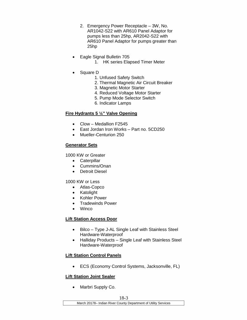
March 20178– Indian River County Department of Utility Services
18-3
2. Emergency Power Receptacle – 3W, No. AR1042-S22 with AR610 Panel Adaptor for pumps less than 25hp, AR2042-S22 with AR610 Panel Adaptor for pumps greater than 25hp
• Eagle Signal Bulletin 705 1. HK series Elapsed Timer Meter
• Square D 1. Unfused Safety Switch 2. Thermal Magnetic Air Circuit Breaker 3. Magnetic Motor Starter 4. Reduced Voltage Motor Starter 5. Pump Mode Selector Switch 6. Indicator Lamps
Fire Hydrants 5 ¼” Valve Opening
• Clow – Medallion F2545
• East Jordan Iron Works – Part no. 5CD250
• Mueller-Centurion 250 Generator Sets 1000 KW or Greater
• Caterpillar
• Cummins/Onan
• Detroit Diesel 1000 KW or Less
• Atlas-Copco
• Katolight
• Kohler Power
• Tradewinds Power
• Winco
Lift Station Access Door
• Bilco – Type J-AL Single Leaf with Stainless Steel Hardware-Waterproof
• Halliday Products – Single Leaf with Stainless Steel Hardware-Waterproof
Lift Station Control Panels
• ECS (Economy Control Systems, Jacksonville, FL)
Lift Station Joint Sealer
• Marbri Supply Co.

March 20178– Indian River County Department of Utility Services
18-4
1. Embeco 636 Grout 2. Embeco 885 Grout
Lift Station and Manhole Sealant and Coatings
• Pro-Tech EW-1 Water Base Epoxy
• CANUSA WRAPID SEAL Lift Station Submersible Pumps
• ABS Pump - If a grinder pump is proposed, only ABS type grinder pumps under 5.0 hp are permitted. ABS V2 Pirana Grinder Pumps are not permitted
• Xylem Flygt. Lift Station Valve Pit Access Door
• Bilco
• Halliday Products Lift Station Valve Pit Quick Disconnect
• Kamloc Male Kwik Disconnect
• Kamloc Coupler 4”
Lift Station Valve Pit Safety Grate
• Halliday Products
• Bilco
Line Setter for Meter Boxes 6” – Part # Retro-2BVBHH-NL 5/8” X 3/4” Meter Retrosetter 12” – Part # VHH42-12W-NL 5/8” X 3/4" Meter Retrosetter No Lead 3/4" Key Valve By Dual Check Valve
• Ford Meter Box Marker Balls Electronic
• 3M – Water 3M 1403XR, Sewer 3M 1404XR Manhole Frames and Covers
• U. S. Foundry – Drawing No. 420-C
• PAM –Pamrex Hinged Manhole Cover and Frame
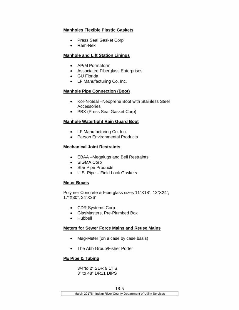
March 20178– Indian River County Department of Utility Services
18-5
Manholes Flexible Plastic Gaskets
• Press Seal Gasket Corp
• Ram-Nek Manhole and Lift Station Linings
• AP/M Permaform
• Associated Fiberglass Enterprises
• GU Florida
• LF Manufacturing Co. Inc. Manhole Pipe Connection (Boot)
• Kor-N-Seal –Neoprene Boot with Stainless Steel Accessories
• PBX (Press Seal Gasket Corp) Manhole Watertight Rain Guard Boot
• LF Manufacturing Co. Inc.
• Parson Environmental Products Mechanical Joint Restraints
• EBAA –Megalugs and Bell Restraints
• SIGMA Corp
• Star Pipe Products
• U.S. Pipe – Field Lock Gaskets Meter Boxes Polymer Concrete & Fiberglass sizes 11”X18”, 13”X24”, 17”X30”, 24”X36”
• CDR Systems Corp.
• GlasMasters, Pre-Plumbed Box
• Hubbell
Meters for Sewer Force Mains and Reuse Mains
• Mag-Meter (on a case by case basis)
• The Abb Group/Fisher Porter PE Pipe & Tubing 3/4”to 2” SDR 9 CTS 3” to 48” DR11 DIPS
March 20178– Indian River County Department of Utility Services
18-6
• Chevron-Phillips
• Flying W Plastics Inc.
• JM Eagle
• Municiplex
• Polypipe
Plug Valves
• Clow Valve Co
• DeZurik-Series 100
• Henry Pratt Co.
• Kennedy Valve
• M&H Valve Co.
• Val-Matic-Series 1500 PVC Pipe & Fittings
Water/Force Main - DR18 C900/C909 (for Fittings, see Ductile Iron Fittings on Page 18-2)
Sewer - SDR 26 3034 (for Fittings, see Sewer Fittings ASTM D-3034 on Page 18-7)
• Diamond Plastics
• ETI Pipe and Supply
• Freedom Plastics
• J-M Manufacturing Co. Inc.
• National Pipe and Plastic
• North American Pipe Corp. Reduce Pressure Backflow Preventer Assembly
• AMES Fire and Waterworks - 400SS & 4000SS
• Wilkins –Part No. 975
• FEBCO- Part No. LF825Y
• Watts – Part No. LF909 Remote Telemetry Unit
• DataFlow Systems Inc. - Model TAC II telemetry unit, complete with Model PCU-001 pump control module, BPR backpack radio/TAC pack, power supply with battery backup, Model RTU-03 enclosure, cable and antenna
Resilient Seat Gate Valves
• American Flow Control
• Clow Valve Co.
• Kennedy Valve
• M&H Valve Co.

March 20178– Indian River County Department of Utility Services
18-7
• Mueller Co. Service Saddles-Stainless Steel Straps
• The Ford Meter Box Co.
• JCM Industries
• Romac Industries Inc.
Sewer Fittings ASTM D-3034
• The Harrington Corp./HARCO
• Multi Fittings
• Royal Building Products Sleeve Type Couplings
• The Ford Meter Box Co.
• Smith-Blair - Style 413
• JCM Industries Tapping Sleeves- Stainless Steel
• The Ford Meter Box Co. – Style FTSS
• JCM Industries- Model 432
• Smith-Blair – Style 663
• Romac Industries Inc. Tie Rods
All tie rods shall be stainless steel all-thread rods
Trace Wire Covering
• King Innovation –Dryconn Weatherproof Connectors
• SKRINK WRAP a) 3M-ScotchKote Weatherproofing
Compound b) 3M- Scotch 33 tape
Trace Wire Port
• Snake Pit (Cast Iron Cover)
Valve Boxes (Domestic Heavy Duty)
• East Jordan Iron Works – Long Throat Lid General Foundries Inc
• Tyler Union-USA
• U. S. Foundry

March 20178– Indian River County Department of Utility Services
18-8
Valve Name Plate
• LF Mfg. Co
• Shiedow Bronze Corp.
• Wager Co.

IV – PERMIT APPLICATIONSAND CHECKLISTS
F:\Utilities\UTILITY - CONSTRUCTION STANDARDS\MARCH 2018\Documents MARCH 2018\Utility Construction Permit-03-2017-UCP CHECKLIST REVISION.docm
INDIAN RIVER COUNTY DEPARTMENT OF UTILITY SERVICES 1801 27th Street, Vero Beach, Florida 32960
UTILITY CONSTRUCTION PERMIT
Permit Issuance Date: Choose an item. Choose an item., Choose an item.
UCP #:
IRC Project #:
Project Name:
Project Location:
Owner/Developer:
Engineer-of-Record: Choose an item. Choose an item.
IRCDUS Inspector: Choose an item.
Project Description: Choose an item.
Services: County Water County Gravity Sewer County Wastewater Force Main
County Lift Station Private Lift Station County Reuse Water
General:
This Utility Construction Permit authorizes the above-named Owner/Developer to construct a Choose an item. Choose an item. for the project as shown on the construction plans prepared by Choose an item., and signed and sealed on Choose an item. Choose an item., Choose an item.. Permit Issuance is contingent upon construction being performed by personnel currently licensed in the State of Florida to perform such work. All work shall be performed in accordance with Indian River County Utilities Standards, latest edition and applicable regulatory agency. Utility work shall not commence until all necessary easements and/or permits are acquired, including an Indian River County R-O-W Permit if working within its limits. The limits of construction are delineated by these plans. This permit is valid for a period of twelve (12) consecutive months from the date of issuance and is subject to the special provisions and completion of associated checklist items as provided in Attachment A; this permit does not constitute a permit for operation.

F:\Utilities\UTILITY - CONSTRUCTION STANDARDS\MARCH 2018\Documents MARCH 2018\Utility Construction Permit-03-2017-UCP CHECKLIST REVISION.docm
Special Conditions:
If you have any questions, please do not hesitate to contact me at (772) 567-8000, ext. Choose an item.
Sincerely,
________________________
Choose an item.
Enclosure: Choose an item.
cc: Vincent Burke, PE, Director of Utility Services (via email)
Richard B. Szpyrka, PE, Director of Public Works (via email)
Stan Boling, AICP, Director of Community Development (via email)
Choose an item. (w/ Enclosure)
Utility Project File UCP # (w/ Enclosure)

ATTACHMENT A
UTILITY CONSTRUCTION PERMIT – SPECIAL PROVISIONS
ATTACHMENT A - PAGE 1
1. The Owner/Developer or his duly authorized representative, the Engineer-of-Record, property owner and construction contractor shall hold Indian River County harmless in any suits, claims, and/or liabilities arising from subject construction.
2. The Owner/Developer or his duly authorized representative, the Engineer-of-Record and the construction contractor shall have a pre-construction meeting with Indian River County Department of Utility Services (IRCDUS) a minimum of five working days before beginning construction.
3. The contractor shall notify Customer Service, IRCDUS, at (772) 567-8000 a minimum of 48 hours prior to beginning construction or performing any system tests.
4. All water and sewer utility locations are to be coordinated with other utilities such as, but not limited to electric, cable, telephone, irrigation, etc. Minimum setback requirements from water and sewer utilities, as outlined below, must be adhered to prior to acceptance of the water and sewer utilities.
Type of Object Min. Horizontal Separation between
Utility Water/Sanitary Lines and other Utilities & Objects
a) Aboveground permanent objects (i.e. walls, trees, transformer pads, etc.).
Pressure Pipes = Depth of the pipe plus diameter of the pipe
Gravity Sewer – ten (10) feet
b) Underground utility lines (i.e., telephone, power, drainage, etc.)
Four (4) feet
c) Surface water body top of bank (i.e. lakes, ponds, canals, etc.).
Two times the depth of the pipe plus the diameter of the pipe
FINAL ACCEPTANCE OF WATER AND SEWER IS CONTINGENT UPON A FINAL INSPECTION BY THE UTILITIES DEPARTMENT AFTER ALL OTHER ON-SITE UTILITIES HAVE BEEN INSTALLED SO THAT MINIMUM SEPARATION REQUIREMENTS, AS OUTLINED ABOVE, CAN BE VERIFIED.
5. This Utility Construction Permit does not eliminate the necessity to obtain a right-of-way permit from Indian River County Public Works Department or other permits that are required by the Florida Department of Environmental Protection (FDEP) or any other county, state, or federal agencies.
6. No construction shall begin until all required easements have been acquired.

ATTACHMENT A
UTILITY CONSTRUCTION PERMIT – SPECIAL PROVISIONS
ATTACHMENT A - PAGE 2
7. All applicable permits allowing utilities construction inside any right-of-way shall be submitted prior to commencement of construction. The Land Development Permit must be obtained, if applicable, prior to commencement of any utility construction.
8. Capacity Charges must be paid in full prior to commitment of capacity or issuance of building permit whichever comes first. THERE IS NO GUARANTEE THAT CAPACITY WILL BE AVAILABLE AT TIME OF REQUEST.
9. County Inspection Services: The County’s hours of peration for this project is limited to between the hours of 8:00 a.m. and 4:00 p.m., Monday through Friday, excluding holidays. The DEVELOPER shall coordinate needed inspection services between these hours of operation. Should the DEVELOPER require County inspection services beyond the designated hours then the DEVELOPER shall pay the inspectors’ hourly prevailing rate times an overtime direct multiplier of 1.5 times the hourly rate. The DEVELOPER shall not have the right to declare this Agreement in default because it disagrees with the fees and charges imposed for the extended use of the County Inspectors.
10. All equipment, materials, and workmanship shall meet or exceed current Indian River County Water and Wastewater Utility Standards and shall be subject to the unconditional inspection and approval of the Indian River County Department of Utility Services.
11. Only IRCDUS approved appurtenances shall be used in construction.
12. Shop drawings shall be provided and reviewed by IRCDUS prior to construction.
13. The Engineer-of-Record (EOR) shall have an on-site representative (inspector) whom shall witness and document all materials used, installation procedures, problems encountered and all tests specified by the Utility Construction Permit Checklist. Daily construction reports shall be submitted not less than monthly to IRCDUS. The daily reports shall be signed and sealed by the EOR. The daily construction reports shall be submitted to IRCDUS no later than seven days after completion of that portion of construction requiring clearance. Indian River County has unconditional rights to inspect the construction and materials at any time.
14. All connections to the IRCDUS system and operation of utility system valves and equipment shall be made under the direct observation of personnel from IRCDUS. Where loss of utility service will occur, a minimum of a 48-hour notice to IRCDUS and the public is required. A 48-hour notice is required for access to private property.

ATTACHMENT A
UTILITY CONSTRUCTION PERMIT – SPECIAL PROVISIONS
ATTACHMENT A - PAGE 3
15. No testing of potable water or sanitary sewer system shall commence until Record Drawings have been submitted, approved, and accepted by the Department of Utility Services.
16. Upon completion of construction, utility system shall be flushed, disinfected, and tested in accordance with the current IRCDUS Specifications.
17. Project Closeout: At the time of final completion, an inspection shall be held by IRCDUS in the presence of the property owner, DEVELOPER, Contractor and Engineer-of-Record. At this time, the DEVELOPER shall provide all necessary documentation as required by the Utility Construction Permit and regulatory agencies, such as the FDEP. At the time of completion of all utility work, a final inspection shall be held. The DEVELOPER shall make arrangements with the Owner, Contractor, Engineer-of-Record and IRCDUS for a joint follow-up inspection and shall send a written notice to said parties to inform them of the date and time of the inspection. After the inspection, IRCDUS, through the Engineer-of-Record, shall inform the DEVELOPER of any corrections required.
18. The one-year maintenance period shall not commence until a final Certification-of-Construction – Completion and Request for Clearance to Place Permitted Components Into Operation (FDEP Form 62-555.900) has been prepared and approved by FDEP, and a Memo of Acceptance has been issued by IRCDUS.
19. Partial Utilization: IRCDUS shall have the right to utilize or place into service any utility equipment pursuant to FDEP Certificate-of-Construction Completion (FDEP Form 62-555.900) or other usable portion of the work prior to completion of the work. In such case, IRCDUS, identifying the specific portion or portions of the work to be so utilized or otherwise placed into service, will notify the DEVELOPER in writing. The DEVELOPER shall understand that until such written notification is issued, all responsibility for ownership, care and maintenance of the work shall be borne by the DEVELOPER. Upon issuance of said written notice of partial utilization, the DEVELOPER accept full responsibility for the protection and maintenance of all such items or portions of the work described in the written notice until final acceptance by IRCDUS. The DEVELOPER shall retain full responsibility for satisfactory completion of the work, regardless of whether a portion thereof has been partially utilized by IRCDUS and the DEVELOPER’S one-year correction period shall commence only after the date of Substantial Completion for the work. DEVELOPER shall be further responsible for submitting a final Certification-of-Construction Completion to FDEP for any outstanding portion of the work.
20. ALL IRCDUS REQUIRED DOCUMENTS / SUBMISSIONS MUST BE PROVIDED BY THE DEVELOPER PRIOR TO IRCDUS’S RELEASE OF THE PROJECT. Upon completion of construction and prior to placing the utility system into service, the requirements of IRCDUS’s water and wastewater system Utility Construction Permit Checklist shall be satisfied. This shall include but is not limited to record drawings, easement dedications, bill-of-sales, etc.

ATTACHMENT A
UTILITY CONSTRUCTION PERMIT – SPECIAL PROVISIONS
ATTACHMENT A - PAGE 4

ATTACHMENT A - PAGE 5
INDIAN RIVER COUNTY
DEPARTMENT OF UTILITY SERVICES
UTILITY CONSTRUCTION PERMIT CHECKLIST
Choose an item.
Received Description
1. One (1) signed and dated, approved or red-lined set of as-built construction drawings by the project’s County Inspector for approval by Utilities Engineering, prior to the submittal of the Final Record Drawings. Submittal of Final Record Drawings should consist of one (1) set of reproducible mylars, one (1) electronic disc and three (3) sets of blue/black line prints signed and sealed by the Engineer-of-Record or Licensed Surveyor. The Engineer-of-Record must be registered to practice in the State of Florida.
2. Copy of a satisfactory hydrostatic pressure test signed by the Engineer-of-Record.
3. One complete set of daily field inspection records prepared by the on-site inspector
certified by the Engineer-of-Record to be submitted seven (7) days after completion of that portion requiring clearance.
4. Copy of a satisfactory bacteriological main clearance certified by the Engineer-of-Record.
5. Copy of a satisfactory trench backfill and compaction density test reports signed by the Engineer-of-Record.
6. Certification by the Engineer-of-Record that the water line was sanitized in accordance with County specifications.
7. Certification by the Engineer-of-Record that the construction of the water distribution system is complete and in accordance with County construction and material specifications. Any deviation from the approved construction drawings or County specifications must be specifically identified and justified by the Engineer.
8. Copy of the Notice of Acceptance of Completion from the Florida Department of
Environmental Protection (FDEP) authorizing the water distribution system to be placed into service.
9. Backflow Preventer Certification(s), which includes domestic and fire lines and proof that the certification has been filed in accordance with the County Cross Connection Control Program’s Backflow Management and Inspection Database. See http://www.ircutilities.com/CCCP.htm for further information.
10. Bill of Sale & Easement - Dedication of the water distribution system and accompanying easements. The dedication is to include an itemized list of all materials along with total materials, construction and engineering costs. This should be coordinated through the IRC Attorney’s Office.

ATTACHMENT A - PAGE 6
Received Description
11. Bill of Sale - Where the water distribution system is located in established easements or road rights-of-way, the attached bill of sale is to be executed along with an itemized list of all materials to include materials and construction costs. This should be coordinated through the IRC Attorney’s Office.
12. Complete on-site inspection by a County utility inspector with confirmation that the water distribution system appears acceptable.
13. Arrangements for payment of all capacity charges and other costs of connections.
14. Release of lien(s) from each Contractor, Subcontractor and Vendor.
15. A one-year maintenance bond in an amount equaling 25% of the total cost for construction of the system if construction costs exceed $10,000. If total construction costs are less than $10,000, then a one-year warranty letter is required. The warranty letter can be issued by the developer or contractor.

ATTACHMENT A - PAGE 7
INDIAN RIVER COUNTY
DEPARTMENT OF UTILITY SERVICES
UTILITY CONSTRUCTION PERMIT CHECKLIST
Choose an item.
Received Description
1. One (1) signed and dated, approved or red-lined set of as-built construction drawings by the project’s County Inspector for approval by Utilities Engineering, prior to the submittal of the Final Record Drawings. Final Record Drawings submittal should consist of one (1) set of reproducible mylars, one (1) electronic disc and three (3) sets of blue/black line prints signed and sealed by the Engineer-of-Record or Licensed Surveyor. The Engineer-of-Record must be registered to practice in the State of Florida.
2. Copy of a satisfactory hydrostatic pressure test or infiltration/exfiltration test signed by the Engineer-of-Record.
3. One complete set of daily field inspection records prepared by the on-site inspector certified
by the Engineer-of-Record to be submitted seven (7) days after completion of construction of that portion requiring clearance.
4. Copy of a satisfactory television test and a certified report by the Engineer-of-Record.
5. Copy of a satisfactory trench backfill and compaction density test reports signed by the Engineer-of-Record.
6. Certification by the Engineer-of-Record that the construction of the wastewater collection/transmission system is complete and in accordance with County construction and material specifications. Any deviation from the approved construction drawings or County specifications must be specifically identified and justified by the Engineer.
7. Copy of the Notice of Acceptance of Completion from the Florida Department of
Environmental Protection (FDEP) authorizing the wastewater collection/transmission system to be placed into service.
8. Bill of Sale & Easement - Dedication of the wastewater collection/transmission system and accompanying easements. The dedication is to include an itemized list of all materials along with total materials, construction and engineering costs. This should be coordinated through the IRC Attorney’s Office.
9. Bill of Sale - Where the wastewater collection/transmission system is located in established easements or road rights-of-way, the attached bill of sale is to be executed along with an itemized list of all materials to include materials and construction costs. This should be coordinated through the IRC Attorney’s Office.
10. Complete on-site inspection by a County utility inspector with confirmation that the wastewater collection/transmission system appears acceptable.

ATTACHMENT A - PAGE 8
Received Description
11. Arrangements for payment of all capacity charges and other costs of connections.
12. Release of lien(s) from each Contractor, Subcontractor and Vendor.
13. A one-year maintenance bond in an amount equaling 25% of the total cost for construction of the system if construction costs exceed $10,000. If total construction costs are less than $10,000, then a one-year warranty letter is required. The warranty letter can be issued by the developer or contractor.
14. A set of lift station specifications (if applicable), two sets of operations and maintenance manuals, warranty, and all spare parts as required by IRCDUS standards.
15. Transfer of lift station’s electric account from Developer to County.
16. If a PRIVATE Lift Station, an acknowledgment letter from Engineer/Owner, and copy of 24/7
lift station maintenance agreement with a qualified service and repair company having lift station maintenance experience.

ATTACHMENT A - PAGE 9
Lift Station Start-Up and Testing Form
COUNTY OF INDIAN RIVER Department of Utilities
Location: Station #:
Wet Well Size: Pumps:
Date: Owner:
Other
Wet Well Diameter
36"
48"
60"
72"
84"
96"
108"
Gal. Per / Ft.
53.04
84.36
146.04
211.44
287.76
375.84
475.68
Gal. Per / Inches
4.42
7.03
12.17
17.62
23.98
31.32
39.64
Serial No:
Design Amperage: Amps
Pump #
N E S W (Circle One)
Serial No.:
Design Amperage: Amps
Pump #
N E S W (Circle One)
Current Balance Check
T 1 = Amps
T 2 = Amps
T 3 = Amps
Current Balance Check
T 1 = Amps
T 2 = Amps
T 3 = Amps
DRAW DOWN TEST
Water Level (Ref. Point )
Finish Inches Time
Start Inches Time
Difference Inches Time
Water Level (Ref. Point )
Finish Inches Time
Start Inches Time
Difference Inches Time
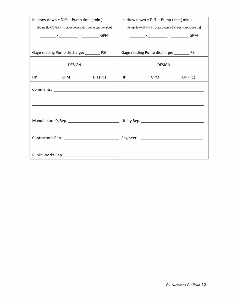
ATTACHMENT A - PAGE 10
In. draw down = Diff. ÷ Pump time ( min )
[Pump flow/GPM = In. draw down x Gal. per in.\station size]
x = GPM
Gage reading Pump discharge: PSI
In. draw down = Diff. ÷ Pump time ( min )
[Pump flow/GPM = In. draw down x Gal. per in.\station size]
x = GPM
Gage reading Pump discharge: PSI
DESIGN
DESIGN
HP GPM TDH (Ft.)
HP GPM TDH (Ft.)
Comments:
Manufacturer’s Rep. Utility Rep.
Contractor’s Rep. Engineer
Public Works Rep.

Project Name:
Project Location:
Inspected By: Date:
ATTACHMENT A - PAGE 11
SECTION A: WET WELL Yes No
A1. All inspections require the wet well to be completely dry and free of any construction debris.
A2. Does wet well appear to be at proper elevation?
A3. Are all joints sealed properly with Ram-neck or other approved preformed gasket
Material and/or non-shrinking, non-metallic grout?
A4. Have all joints been sealed over properly with non-shrink wrap?
A5. Has bottom bench wall been installed correctly?
A6. Have the base plates been installed correctly and inspected by lift station personnel?
(Lift station mechanic initials for approval: ____)
A7. Has wet well been lined properly?
A8. Has the vent been installed properly with the approved materials?
A9. Has the vent been installed in the proper location and height?
A10. Has stainless steel insect screen been installed in the vent?
A11. Does the access cover operate properly?
A12. Is H20 loading required for the access cover?

Project Name:
Project Location:
Inspected By: Date:
ATTACHMENT A - PAGE 12
A13. If required, is the access cover rated properly?
A14. Does the access cover have any broken hardware?
A15. Were there any leaks in the wet well?
A16. Have all leaks been repaired properly?
A17. Have lifting rings been removed and grouted?
A18. Did I notify Contractor and Engineer about any and all items checked “No” in Section A?
A19. Has concrete been poured around the hold down collar at the bottom of the wet
well to counteract buoyancy?
COMMENTS:
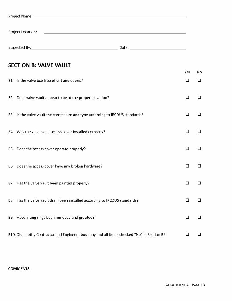
Project Name:
Project Location:
Inspected By: Date:
ATTACHMENT A - PAGE 13
SECTION B: VALVE VAULT Yes No
B1. Is the valve box free of dirt and debris?
B2. Does valve vault appear to be at the proper elevation?
B3. Is the valve vault the correct size and type according to IRCDUS standards?
B4. Was the valve vault access cover installed correctly?
B5. Does the access cover operate properly?
B6. Does the access cover have any broken hardware?
B7. Has the valve vault been painted properly?
B8. Has the valve vault drain been installed according to IRCDUS standards?
B9. Have lifting rings been removed and grouted?
B10. Did I notify Contractor and Engineer about any and all items checked “No” in Section B?
COMMENTS:
Project Name:
Project Location:
Inspected By: Date:
ATTACHMENT A - PAGE 14

Project Name:
Project Location:
Inspected By: Date:
ATTACHMENT A - PAGE 15
SECTION C: PIPING GENERAL Yes No
C1. All piping shall be in accordance with IRCDUS standards.
C2. Is all discharge piping flanged pipe ductile iron?
C3. Are all bolts and nuts stainless steel?
C4. Has all electrical conduit and piping entering or exiting wet well and valve box been
properly grouted and painted?
C5. Does all piping appear to be plumbed and straight?
C6. Are all clearances between piping and pre-cast (concrete) according to IRCDUS standards?
C7. Are all piping materials approved by IRCDUS? (i.e., check valves, plug valves, etc.)
SECTION C1: WATER SERVICE PIPING
C8. Is water available at lift station site?
C9. Is copper or brass piping used for service?
C10. Has a R.P.Z. type back-flow preventer been installed?
C11. Has the water service been installed by or attached to the panel assembly in an approved

Project Name:
Project Location:
Inspected By: Date:
ATTACHMENT A - PAGE 16
manner? (No stainless steel hose clamps.)
C12. Is the back-flow preventer leaking?
C13. Has the back-flow preventer been tested and certified?
C14. Has hose bibb been installed?
C15. Did I notify Contractor and Engineer about any and all items checked “No” in Section C?
COMMENTS:

Project Name:
Project Location:
Inspected By: Date:
ATTACHMENT A - PAGE 17
SECTION D: GENERAL APPEARANCE Yes No
D1. Does station require a fence?
D2. If fence is required, is fence installed properly?
D3. Does fence material conform to IRCDUS standards?
D4. Is the fence gate the proper size?
D5. Is gate installed in the proper location?
D6. Does grading around station appear to be smooth and clear of any construction debris?
D7. Has sod been installed?
D8. Does sod appear to be installed in a satisfactory manner?
D9. Did I notify the Contractor and Engineer about any and all items checked
“No” in Section D?
COMMENTS:

Project Name:
Project Location:
Inspected By: Date:
ATTACHMENT A - PAGE 18

Project Name:
Project Location:
Inspected By: Date:
ATTACHMENT A - PAGE 19
SECTION E: ELECTRICAL CONTROL PANEL Yes No
E1. Are all electrical component supplies (i.e., panel, disconnect) installed in accordance
with IRCDUS standards?
E2. Is the panel supplied for the proper size?
E3. Is the panel set up for a Remote Telemetry Unit (R.T.U.)?
E4. Is the R.T.U. installed?
E5. Are the panel support posts (schedule 40 min.) stainless steel?
E6. Is the panel the proper height above finished grade?
E7. Is the mounting hardware (i.e., bolts, nuts, fasteners, strut, conduit straps) stainless
steel (no galvanized) or aluminum?
E8. Is the disconnect stainless steel?
E9. Is the disconnect non-fusible?
E10. Is the panel installed in the proper location?
E11. Are all electrical conduits installed according to IRCDUS standards?
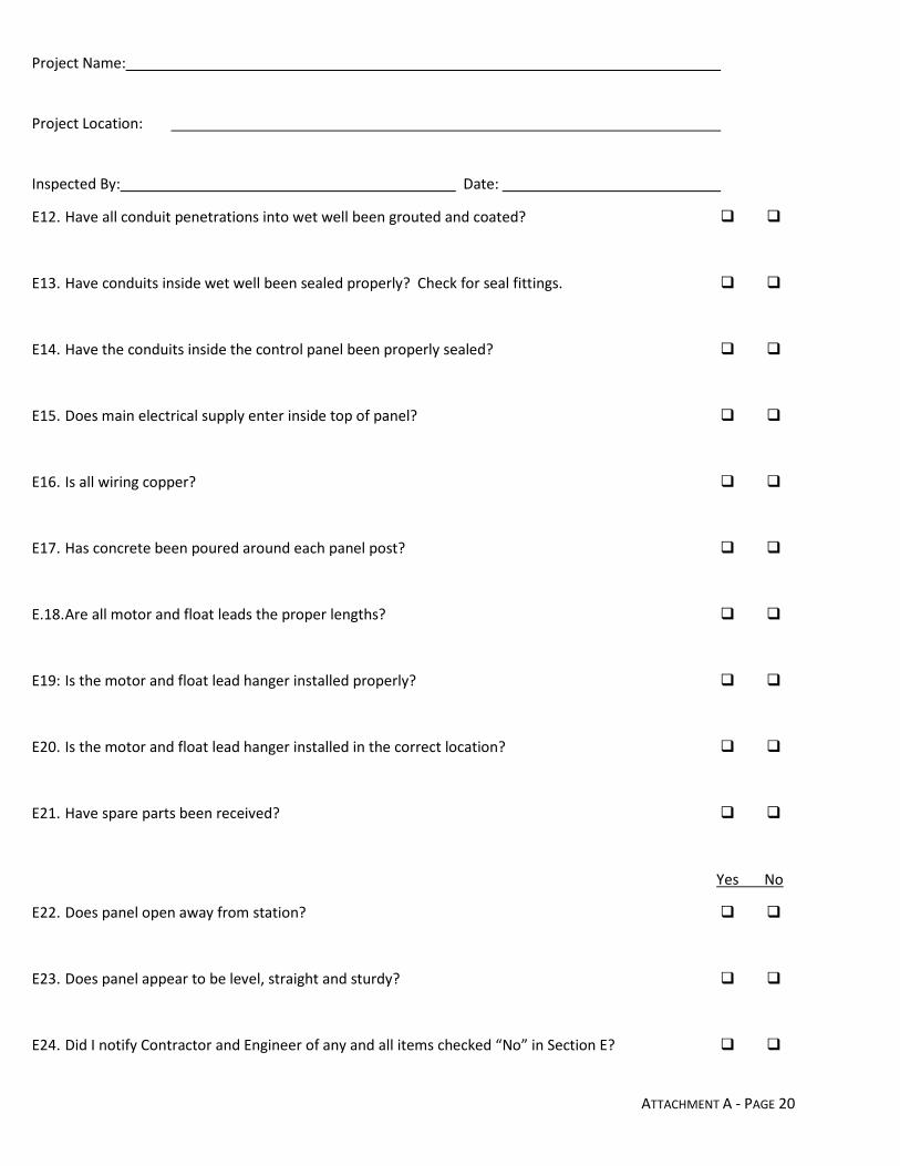
Project Name:
Project Location:
Inspected By: Date:
ATTACHMENT A - PAGE 20
E12. Have all conduit penetrations into wet well been grouted and coated?
E13. Have conduits inside wet well been sealed properly? Check for seal fittings.
E14. Have the conduits inside the control panel been properly sealed?
E15. Does main electrical supply enter inside top of panel?
E16. Is all wiring copper?
E17. Has concrete been poured around each panel post?
E.18. Are all motor and float leads the proper lengths?
E19: Is the motor and float lead hanger installed properly?
E20. Is the motor and float lead hanger installed in the correct location?
E21. Have spare parts been received?
Yes No
E22. Does panel open away from station?
E23. Does panel appear to be level, straight and sturdy?
E24. Did I notify Contractor and Engineer of any and all items checked “No” in Section E?

Project Name:
Project Location:
Inspected By: Date:
ATTACHMENT A - PAGE 21
E25. Have the hours been recorded on both Elapsed Time Meters at start-up?
E26. Have the Hand-Off-Automatic Switches been checked to see if they operate properly?
E27. Do the indicator lights light up for each pump when operating?
E28. Does the Lock Out Plate for the Motor Control Breaker and the Emergency Generator
Breaker work properly?
E29. Does the alternating relay for both pumps function properly?
E30. Does the alarm light and horn function properly?
E31. Does the Alarm Silence button shut off the alarm?
E32. Has the Ground Fault Interrupter on the Duplex Receptacle been tested and does
it work properly?
E33. If the lift station is private, is there a label posted on the station stating the name and
24-hour emergency phone number of the firm responsible for operation and maintenance?
E34. Are the spare fuses located inside the control panel for the control circuit?
E35. Are all the wires tight on the terminal blocks and motor starters?
E36. Does the panel door shut securely rendering the panel watertight?

Project Name:
Project Location:
Inspected By: Date:
ATTACHMENT A - PAGE 22
E37. Is there a lightning arrestor or surge protector in the control panel?
E38. Is there a copper ground rod for the panel and is the lift station properly connected to it?
E39. Prior to start-up, have the check valves in the valve vault been checked to see if
they are in the open position?
E40. Prior to start-up, have the check valves in the valve vault been checked to see if they
have been installed in the right direction of flow?
E41. Prior to start-up, have the pumps been properly seated on their base elbows at the
bottom of the wet well?
Yes No
E42. Upon start-up, if the pumps do not draw down the liquid level in the wet well,
have they been checked for an air lock in the volute?
E43. Upon start-up, does the liquid level control system function properly for the lead pump
on, the lag pump on, the high level alarm, and shut off levels?
E44. Is there a safety grate installed over the wet well?
COMMENTS:

Project Name:
Project Location:
Inspected By: Date:
ATTACHMENT A - PAGE 23