Wastewater Land Application Operators Study and … · CEC cation exchange capacity cmol centimols...
358
Wastewater Land Application Operators Study and Reference Manual State of Idaho Department of Environmental Quality May 2014
-
Upload
nguyenminh -
Category
Documents
-
view
218 -
download
0
Transcript of Wastewater Land Application Operators Study and … · CEC cation exchange capacity cmol centimols...
Wastewater Land Application Operators Study and Reference
Manual
State of Idaho
Department of Environmental Quality
May 2014

Printed on recycled paper, DEQ, April 2014, PID WTR.WWPA.WLOF.0505, CA 82027. Costs associated with this publication are available from the State of Idaho Department of Environmental Quality in accordance with Section 60-202, Idaho Code.
Wastewater Land Application Operators Study and Reference
Manual
May 2014
Prepared by Idaho Department of Environmental Quality
Water Quality Division 1410 N. Hilton
Boise, ID 83706
Acknowledgments
This manual is a combination of guidance materials gathered from various technical resources,
with input and expertise from the Idaho Department of Environmental Quality wastewater
engineering and technical staff.
Special thanks are extended to the North Carolina Department of Environment and Natural
Resources for allowing the use of the Spray Irrigation Systems Operators Training Manual
(N.C. DENR 2001) as an immensely valuable starting point in the production of this manual.
Wastewater Land Application Operators Study and Reference Manual
iii
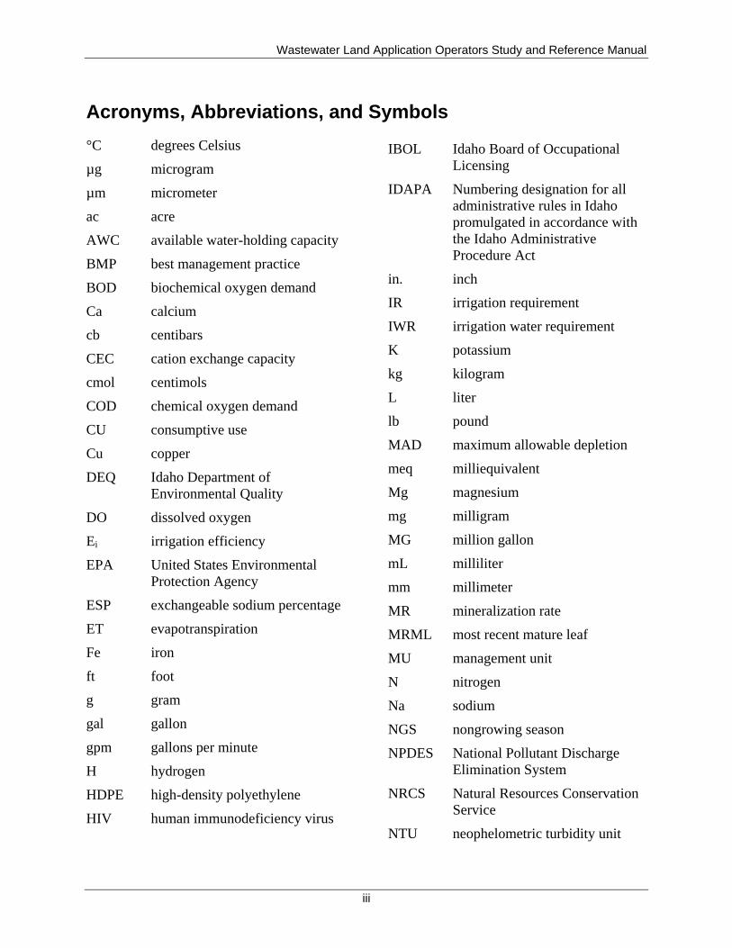
Acronyms, Abbreviations, and Symbols
°C degrees Celsius
µg microgram
µm micrometer
ac acre
AWC available water-holding capacity
BMP best management practice
BOD biochemical oxygen demand
Ca calcium
cb centibars
CEC cation exchange capacity
cmol centimols
COD chemical oxygen demand
CU consumptive use
Cu copper
DEQ Idaho Department of
Environmental Quality
DO dissolved oxygen
Ei irrigation efficiency
EPA United States Environmental
Protection Agency
ESP exchangeable sodium percentage
ET evapotranspiration
Fe
iron
ft foot
g gram
gal gallon
gpm gallons per minute
H hydrogen
HDPE high-density polyethylene
HIV human immunodeficiency virus
IBOL Idaho Board of Occupational
Licensing
IDAPA Numbering designation for all
administrative rules in Idaho
promulgated in accordance with
the Idaho Administrative
Procedure Act
in. inch
IR irrigation requirement
IWR irrigation water requirement
K potassium
kg kilogram
L liter
lb pound
MAD maximum allowable depletion
meq milliequivalent
Mg magnesium
mg milligram
MG million gallon
mL milliliter
mm millimeter
MR mineralization rate
MRML most recent mature leaf
MU management unit
N nitrogen
Na sodium
NGS nongrowing season
NPDES National Pollutant Discharge
Elimination System
NRCS Natural Resources Conservation
Service
NTU neophelometric turbidity unit
Wastewater Land Application Operators Study and Reference Manual
iv
NVDS nonvolatile dissolved solid
NVSS nonvolatile suspended solid
O&M operations and maintenance
(manual)
OSHA Occupational Safety and Health
Administration
P phosphorus
PAN plant-available nitrogen
PAPR powered air-purifying respirators
PAW plant-available water
Pdef precipitation deficit
Pe effective precipitation
PO plan of operations
PPE personal protective equipment
ppm parts per million
psi pounds per square inch
PVC polyvinyl chloride
QAPP quality assurance project plan
RI rapid infiltration
SAR sodium adsorption ratio
SCBA self-contained breathing
apparatus
SU soil monitoring unit
TDS total dissolved solid
TKN total Kjeldahl nitrogen
TSS total suspended solid
USDA United States Department of
Agriculture
UV ultraviolet
V volt
VDS volatile dissolved solid
VR volatilization rate
VSS volatile suspended solid
WWLA wastewater land application
yr year
Zn zinc
Needs-to-know criteria
Wastewater Land Application Operators Study and Reference Manual
v
Table of Contents
Acronyms, Abbreviations, and Symbols ....................................................................................... iii
Introduction ................................................................................................................................... xv
Purpose of This Manual ................................................................................................................ xv
This Manual and the Law ............................................................................................................. xv
How This Manual Was Developed .............................................................................................. xvi
Updates to This Manual ............................................................................................................... xvi
1 Roles and Responsibilities of the Wastewater Land Application Operator ............................ 1
1.1 Permits ................................................................................................................................ 1
1.1.1 Municipal Reuse Permit .............................................................................................. 1
1.1.2 Industrial Reuse Permit ................................................................................................ 2
1.1.3 Combined Reuse Permit .............................................................................................. 2
1.2 Rules ................................................................................................................................... 2
2 Recycled Water Classes (A-E) ................................................................................................ 3
2.1 Class A Recycled Water ..................................................................................................... 6
2.2 Class B Recycled Water...................................................................................................... 8
2.3 Class C Recycled Water...................................................................................................... 9
2.4 Class D Recycled Water ................................................................................................... 10
2.5 Class E Recycled Water .................................................................................................... 10
2.6 Industrial Recycled Water ................................................................................................. 11
3 Reuse Permit Template .......................................................................................................... 13
3.1 Facility Information .......................................................................................................... 13
3.2 Compliance Activities and Compliance Schedules .......................................................... 14
3.3 Reuse Permit Limits and Conditions ................................................................................ 14
3.3.1 Management Unit Descriptions ................................................................................. 14
3.3.2 Hydraulic-Loading Limits ......................................................................................... 14
3.3.3 Constituent-Loading Limits ....................................................................................... 15
3.3.4 Management Unit Buffer Zones ................................................................................ 15
3.3.5 Other Permit Limits and Conditions .......................................................................... 15
3.4 Reuse Permit Monitoring Requirements ........................................................................... 15
3.4.1 Constituent Monitoring .............................................................................................. 15
3.4.2 Management Unit and Other Flow Monitoring ......................................................... 16
3.4.3 Ground Water Monitoring ......................................................................................... 16
3.4.4 Soil Monitoring .......................................................................................................... 17
3.4.5 Plant Tissue Monitoring ............................................................................................ 17
3.4.6 Lagoon Information ................................................................................................... 17
Wastewater Land Application Operators Study and Reference Manual
vi
3.5 Reporting Requirements ................................................................................................... 17
3.5.1 Annual Reports Requirements ................................................................................... 17
3.5.2 Emergency and Noncompliance Reporting ............................................................... 18
3.6 Permit for Use of Industrial Water .................................................................................... 18
3.7 Standard Permit Conditions .............................................................................................. 19
3.8 General Permit Conditions ................................................................................................ 19
3.8.1 Operations .................................................................................................................. 19
3.8.2 Administrative ........................................................................................................... 19
3.9 Other Applicable Laws ..................................................................................................... 19
3.10 Site Maps .......................................................................................................................... 19
4 Permit Required Documents—Plans ..................................................................................... 21
4.1 Plan of Operations............................................................................................................. 21
4.2 Quality Assurance Project Plan ........................................................................................ 24
5 Reporting and Monitoring Wastewater and Recycled Water Constituents/Parameters ........ 27
5.1 Wastewater ........................................................................................................................ 27
5.2 Wastewater Physical Characteristics ................................................................................ 27
5.2.1 Color .......................................................................................................................... 28
5.2.2 Odor ........................................................................................................................... 28
5.2.3 Temperature ............................................................................................................... 28
5.2.4 Solids ......................................................................................................................... 28
5.3 Other Important Wastewater Characteristics .................................................................... 32
5.3.1 Pathogenic Organisms ............................................................................................... 32
5.3.2 Biochemical Oxygen Demand and Chemical Oxygen Demand ................................ 33
5.3.3 Dissolved Oxygen ...................................................................................................... 34
5.3.4 Nutrients .................................................................................................................... 34
5.3.5 Metals ........................................................................................................................ 37
5.3.6 Persistent Organic Chemicals .................................................................................... 38
5.3.7 pH .............................................................................................................................. 38
5.3.8 Salts ............................................................................................................................ 38
5.4 Hydraulic- and Constituent-Loading Rates ...................................................................... 39
5.4.1 Hydraulic-Loading Rate ............................................................................................ 39
5.4.2 Constituent-Loading Rates ........................................................................................ 40
5.4.3 Land-Limiting Constituent ........................................................................................ 41
6 Soil Monitoring and Reporting and Management for Agronomic Nutrient Uptake ............. 43
6.1 Soil Components and Profiles ........................................................................................... 43
6.1.1 Soil Composition ....................................................................................................... 43
6.1.2 Soil Profiles ............................................................................................................... 44
6.2 Soil Physical Characteristics ............................................................................................. 46
Wastewater Land Application Operators Study and Reference Manual
vii
6.2.1 Soil Texture ............................................................................................................... 46
6.2.2 Soil Structure ............................................................................................................. 51
6.2.3 Organic Material Contents ......................................................................................... 53
6.2.4 Soil Depth .................................................................................................................. 53
6.2.5 Soil Color ................................................................................................................... 54
6.2.6 Soil Drainage/Wetness ............................................................................................... 54
6.2.7 Topography and Landscape Position ......................................................................... 55
6.3 Soil Chemical Characteristics ........................................................................................... 56
6.3.1 Texture and Organic Matter Content ......................................................................... 57
6.3.2 Cation Exchange Capacity ......................................................................................... 57
6.3.3 Sodium Adsorption Ratio .......................................................................................... 60
6.3.4 pH .............................................................................................................................. 60
6.4 Soil Moisture ..................................................................................................................... 61
6.4.1 Plant-Available Water Content .................................................................................. 61
6.4.2 Infiltration .................................................................................................................. 63
6.4.3 Permeability ............................................................................................................... 63
6.5 Soil Treatment of Recycled Water .................................................................................... 64
6.5.1 Physical Treatment .................................................................................................... 64
6.5.2 Chemical Treatment ................................................................................................... 65
6.5.3 Biological Treatment ................................................................................................. 65
6.6 Fate of Water Constituents ................................................................................................ 66
6.7 Agronomy ......................................................................................................................... 67
6.7.1 Essential Nutrients ..................................................................................................... 67
6.7.2 Nutrient Availability and Nutrient Management ....................................................... 69
6.8 Crop Nutrient Requirements ............................................................................................. 77
7 Ground Water and Hydrology ............................................................................................... 79
7.1 Hydrologic Cycle .............................................................................................................. 79
7.2 Evaporation and Evapotranspiration ................................................................................. 80
7.3 Runoff to Surface Waters .................................................................................................. 82
7.3.1 Soil Erosion ............................................................................................................... 82
7.3.2 Surface Water Pollution ............................................................................................. 82
7.3.3 Ponding ...................................................................................................................... 83
7.4 Infiltration into the Soil ..................................................................................................... 83
7.4.1 Soil Water .................................................................................................................. 83
7.4.2 Water Table Depths ................................................................................................... 85
7.4.3 Artificially Affecting Site Hydrology ........................................................................ 87
7.5 Ground Water Monitoring Wells ...................................................................................... 87
7.6 Rapid Infiltration Basins ................................................................................................... 91
Wastewater Land Application Operators Study and Reference Manual
viii
7.7 Summary ........................................................................................................................... 91
8 Recycled Water Disinfection and Buffer Zones .................................................................... 93
8.1 Disinfection ....................................................................................................................... 93
8.1.1 Chlorination ............................................................................................................... 93
8.1.2 Ultraviolet Radiation ................................................................................................. 95
8.1.3 Ozone Disinfection .................................................................................................... 96
8.2 Buffer Zones ..................................................................................................................... 96
9 Lagoons .................................................................................................................................. 99
9.1 Lagoon Design and Configuration .................................................................................... 99
9.2 Lagoon Operation and Maintenance ............................................................................... 101
9.2.1 Vegetation ................................................................................................................ 101
9.2.2 Erosion ..................................................................................................................... 102
9.2.3 Excessive Algae ....................................................................................................... 102
9.2.4 Odor Prevention ....................................................................................................... 103
9.2.5 Insufficient Freeboard .............................................................................................. 103
9.2.6 Short-Circuiting ....................................................................................................... 104
9.2.7 Sludge Accumulation and Removal ........................................................................ 104
10 Distribution Network and Devices ...................................................................................... 107
10.1 Pumps and Controls ........................................................................................................ 107
10.1.1 Pumps ...................................................................................................................... 107
10.1.2 Backflow Prevention Assemblies and Devices ....................................................... 107
10.1.3 Alarms and Timers .................................................................................................. 108
10.1.4 Counters ................................................................................................................... 108
10.1.5 Flowmeters .............................................................................................................. 108
10.2 Distribution Network and Devices.................................................................................. 109
10.2.1 Pipes and Fittings ..................................................................................................... 109
10.2.2 Irrigation Application Devices (Sprinklers) ............................................................ 110
10.3 Operational Issues ........................................................................................................... 116
11 Irrigation Systems Operations and Scheduling .................................................................... 119
11.1 Irrigation Scheduling ...................................................................................................... 119
11.1.1 Determining When to Irrigate .................................................................................. 120
11.1.2 Basic Soil-Water Relationships ............................................................................... 120
11.1.3 Estimating Soil-Water Content ................................................................................ 123
11.2 Determining How Much to Irrigate ................................................................................ 134
11.2.1 Operational Considerations ..................................................................................... 136
11.2.2 Determination of Irrigation Rate for Stationary Sprinklers ..................................... 138
11.2.3 Center Pivot Systems ............................................................................................... 139
11.3 Equipment Calibration and Application Uniformity ...................................................... 139
Wastewater Land Application Operators Study and Reference Manual
ix
11.3.1 Summary of Irrigation Scheduling .......................................................................... 141
12 Sampling .............................................................................................................................. 143
12.1 Soil Sampling .................................................................................................................. 143
12.1.1 Soil Test ................................................................................................................... 144
12.1.2 Sampling Timing ..................................................................................................... 144
12.1.3 Sampling Procedure ................................................................................................. 144
12.1.4 Using a Soil Test to Determine the Land-Limiting Nutrient ................................... 144
12.2 Plant Tissue Sampling..................................................................................................... 145
12.2.1 Taking a Representative Sample ............................................................................. 146
12.2.2 Selecting the Best Indicator Sample for Crop Management ................................... 146
12.2.3 Choosing Sample Size for Crop Management ......................................................... 147
12.2.4 Submitting the Sample ............................................................................................. 147
12.3 Recycled Water Sampling ............................................................................................... 147
12.3.1 Recycled Water Sampling Terminology ................................................................. 148
12.3.2 Sampling Procedures ............................................................................................... 149
12.4 Ground Water Sampling ................................................................................................. 149
12.4.1 Minimizing Contamination Risks ............................................................................ 151
12.4.2 Purging the Well ...................................................................................................... 152
12.4.3 Procedures for Packing Ground Water Samples ..................................................... 154
13 Site Operations and Maintenance ........................................................................................ 155
13.1 Soil Management ............................................................................................................ 156
13.1.1 Ponding, Runoff, Surfacing, or Prolonged Saturation ............................................. 157
13.1.2 Ground Water Mounding ......................................................................................... 157
13.1.3 Surface Crusting ...................................................................................................... 158
13.1.4 Compaction .............................................................................................................. 159
13.1.5 Excess Recycled Water Constituents ....................................................................... 160
13.2 Crop Management ........................................................................................................... 165
13.2.1 Crop Selection ......................................................................................................... 167
13.2.2 Nutrient and Irrigation Management ....................................................................... 169
13.2.3 Pest Control ............................................................................................................. 170
13.2.4 Best Management Practices ..................................................................................... 171
13.2.5 Troubleshooting ....................................................................................................... 174
13.3 Management of Recycled Water Application ................................................................. 176
13.3.1 Uniformity of Recycled Water Distribution ............................................................ 176
13.3.2 Winter Operation ..................................................................................................... 177
13.4 Management of System Components ............................................................................. 178
13.4.1 Land Application Equipment ................................................................................... 178
13.4.2 Drainage Systems .................................................................................................... 181
Wastewater Land Application Operators Study and Reference Manual
x
13.4.3 Soil and Site Components ........................................................................................ 181
13.5 Recordkeeping ................................................................................................................ 182
13.6 Environmental Protection ............................................................................................... 183
13.6.1 Emergency Action Plans for Spills and Releases .................................................... 183
14 Calculations for Annual Reports and Permit Condition Compliance .................................. 187
14.1 Units of Measurement ..................................................................................................... 187
14.2 Types of Calculations ..................................................................................................... 187
14.2.1 Concentration and Constituent-Loading Rate Calculations .................................... 188
14.2.2 Hydraulic-Loading Rate Calculations ..................................................................... 190
14.2.3 Plant-Available Nitrogen Calculations .................................................................... 194
14.2.4 Sodium Adsorption Ratio Calculations ................................................................... 195
14.2.5 Reuse Water Application Rate and Run Time Calculations .................................... 197
14.2.6 Crop Yield and Crop Uptake Calculations .............................................................. 198
15 Health and Safety ................................................................................................................. 201
15.1 Regulatory Overview ...................................................................................................... 201
15.1.1 Employer Responsibilities ....................................................................................... 201
15.1.2 Site Supervisor Responsibilities .............................................................................. 201
15.1.3 Employee Responsibilities ....................................................................................... 202
15.2 Health and Safety Program ............................................................................................. 202
15.2.1 Incident Reporting ................................................................................................... 202
15.2.2 Hazard Communication Standard ............................................................................ 202
15.2.3 Chemical Hygiene Plan ........................................................................................... 203
15.2.4 Personal Protective Equipment ................................................................................ 203
15.3 Health and Safety Hazards .............................................................................................. 211
15.3.1 Health and Safety Measures .................................................................................... 211
15.3.2 OSHA Process Safety Management and EPA Risk Management Programs .......... 211
15.4 Confined Space Safety .................................................................................................... 212
15.5 General Site Safety ......................................................................................................... 214
15.5.1 Lockout/Tagout Policy ............................................................................................ 214
15.5.2 Electrical Safety ....................................................................................................... 215
15.5.3 Mechanical Safety ................................................................................................... 216
15.6 Land Application Site Vehicle Use ................................................................................. 217
15.6.1 Heavy Off-The-Road Vehicle Operation ................................................................. 218
15.7 Lagoon Safety ................................................................................................................. 218
15.8 Fire Prevention and Protection........................................................................................ 218
15.9 Medical Safety ................................................................................................................ 219
15.9.1 First Aid Training .................................................................................................... 219
15.9.2 Blood-Borne Pathogen Awareness .......................................................................... 219
Wastewater Land Application Operators Study and Reference Manual
xi
15.9.3 Eyewash Stations ..................................................................................................... 220
15.9.4 Immunization ........................................................................................................... 220
15.9.5 Personal Hygiene ..................................................................................................... 220
15.9.6 Safe Lifting and Carrying Techniques ..................................................................... 220
15.10 Public Health and Safety ................................................................................................. 221
16 Idaho Rules and Requirements ............................................................................................ 223
16.1 Recycled Water Rules (IDAPA 58.01.17) and Wastewater Rules (IDAPA 58.01.16) .. 224
16.1.1 Application Process for Reuse Permits .................................................................... 224
16.1.2 Permit Renewals ..................................................................................................... 225
16.1.3 Plans and Specification Review ............................................................................... 225
16.1.4 Entry and Access ..................................................................................................... 225
16.1.5 Monitoring and Reporting Requirements ................................................................ 226
16.1.6 Permit Requirements ............................................................................................... 226
16.1.7 Permit Modifications ............................................................................................... 227
16.1.8 Permit Revocation ................................................................................................... 228
16.1.9 Penalties for Permit Violations ................................................................................ 228
16.1.10 Waivers .............................................................................................................. 228
16.2 Ground Water Quality Rule (IDAPA 58.01.11) and Water Quality Standards (IDAPA
58.01.02) ......................................................................................................................... 229
16.3 Wastewater Rules (IDAPA 58.01.16) and IDAPA 24.05.01 as related to Wastewater
Operator Requirements ................................................................................................... 229
16.3.1 Designation and Responsibilities of the Responsible Charge Operator .................. 230
16.3.2 Responsibilities of a Substitute Responsible Charge Operator ............................... 230
16.3.3 Responsibilities of Contract Operators .................................................................... 230
16.3.4 License Requirements Exclusive to Wastewater-Land Application Operators ....... 231
16.3.5 Licensure of Wastewater Land Application Operators ........................................... 231
16.3.6 Responsibilities of Certified Operators ................................................................... 232
16.3.7 Disciplinary Actions ................................................................................................ 232
16.4 Other Regulations ........................................................................................................... 232
17 References ............................................................................................................................ 235
Appendix A. Example Land Application Permits ...................................................................... 239
Appendix B. Monitoring Well Construction Guidance .............................................................. 299
Appendix C. Reuse Permit: Annual Report Information Notes ................................................. 303
Appendix D. Pumps and Motors ................................................................................................. 305
Appendix E. Pipes, Connections, and Valves ............................................................................. 313
Appendix F. Soil Sampling ......................................................................................................... 317
Appendix G. Plant Tissue Sampling ........................................................................................... 325
Appendix H. Ground Water ........................................................................................................ 327
Appendix I. Winterization and Maintenance of Equipment ....................................................... 331
Wastewater Land Application Operators Study and Reference Manual
xii
List ofTables
Table 2-1. Recycled water classification. ....................................................................................... 4
Table 2-2. Class A and Class B additional requirements................................................................ 4
Table 2-3. Recycled water uses. ..................................................................................................... 5
Table 3-1. Constituent monitoring. ............................................................................................... 16
Table 6-1. Size and general characteristics of the three soil particle types. ................................. 47
Table 6-2. Essential macronutrients and micronutrients. .............................................................. 69
Table 6-3. Soil factors that may lead to deficiencies of selected nutrients. .................................. 74
Table 6-4. Key to nutrient disorders. ............................................................................................ 76
Table 11-1. Average estimated plant-available water for various soil texture classes. .............. 123
Table 11-2. Recommended irrigation volumes, as a function of soil texture, based on
estimates of plant-available water using the feel method. ............................................ 124
Table 11-3. Use of the checkbook method for irrigation scheduling soil-moisture balance
sheet (modified from Ashley et al. 1998). .................................................................... 130
Table 11-4. Seasonal crop-root zone development for specific growth stages. .......................... 132
Table 11-5. Percent of plant available soil water (PAW) that may be used without causing
yield or quality losses (maximum allowable depletion). .............................................. 133
Table 11-6. Approximate water infiltration rates for various soil textures and slopes. .............. 135
Table 11-7. Discharge characteristics for rotary impact sprinklers used with permanent
stationary irrigation system. ......................................................................................... 137
Table 11-8. General flow rates and coverage diameter for big gun sprinklers. .......................... 137
Table 12-1. Situations in which the most recent mature leaf is not the best indicator sample. .. 147
Table 13-1. Water quality guidelines for irrigation. ................................................................... 163
Table 13-2. Salt tolerance of forage grasses and legumesa (Bernstein 1958). ............................ 165
Table 13-3. Nitrogen fertilization guidelines (Zublena et al. 1996). .......................................... 167
Table 13-4. Nitrogen rates and timing of recycled water application to minimize soil leaching
losses and luxury consumption by forage plants (Green and Mueller 1996). .............. 170
Table 15-1. Threshold quantities for chemicals requiring a process safety program or risk
management program. .................................................................................................. 212
List of Figures
Figure 4-1. Relationship between the PO, O&M manual, various facility plans, and QAPP. ..... 22
Figure 5-1. Typical composition of solids in raw municipal wastewater (modified from EPA
2004). .............................................................................................................................. 29
Figure 5-2. Analysis for total solids (Butler 2003). ...................................................................... 30
Figure 5-3. Separation of dissolved and suspended solids (Butler 2003). .................................... 31
Figure 5-4. Analysis for suspended volatile and nonvolatile solids (Butler 2003). ...................... 32
Figure 5-5. The nitrogen cycle. ..................................................................................................... 36
Figure 5-6. The phosphorus cycle. ................................................................................................ 37
Figure 6-1. Composition of a medium-textured mineral soil (modified from Brady 1990). ........ 44
Figure 6-2. A typical soil profile and horizons (modified from Brady 1990). ............................. 45
Wastewater Land Application Operators Study and Reference Manual
xiii
Figure 6-3. Representation of the comparative sizes and shapes of sand, silt, and clay particles
(modified from Hillel 1980). .......................................................................................... 47
Figure 6-4. Textural triangle: the major soil textural classes are defined by the percentage of
sand, silt, and clay according to the heavy boundary lines shown on the textural
triangle. ........................................................................................................................... 48
Figure 6-5. Diagram for determining soil textural class by feel (modified from Thien 1979). .... 50
Figure 6-6. Various structural types found in mineral soils (modified from Hillel 1980). ........... 52
Figure 6-7. Cross-sectional and plan view of various landscape positions (Daniels et al. 1984). 56
Figure 6-8. Mineral and organic colloids with adsorbed ions (modified from Brady 1990). ....... 58
Figure 6-9. Ranges in cation exchange capacities (at pH 7) that are typical of a variety of soils
and soil materials. ........................................................................................................... 59
Figure 6-10. Some pH values for familiar substances (above) compared to ranges of pH
typical for various types of soils (below) (Brady and Weil 2008). ................................ 60
Figure 6-11. Volumes of water and air associated with 100 grams of a silt loam soil at
different moisture levels. ................................................................................................ 62
Figure 6-12. Soil treatment of recycled water. ............................................................................. 64
Figure 6-13. Illustration of relationship among soil components that provide nutrient cations
for plants. ........................................................................................................................ 70
Figure 6-14. Relationships existing in mineral soils between pH and the availability of plant
nutrients. ......................................................................................................................... 73
Figure 6-15. Relationship between plant growth and concentration in the soil solution of
elements that are essential to plants. ............................................................................... 75
Figure 7-1. The hydrologic cycle (Brady 1990). .......................................................................... 80
Figure 7-2. The water balance of a root zone (Hillel 1980). ......................................................... 81
Figure 7-3. Divisions of soil water. .............................................................................................. 84
Figure 7-4. Porous aquifer and perched water table above an impermeable layer (Brooks et al.
2003). .............................................................................................................................. 85
Figure 7-5. Ground water characteristics and water table changes from wet to dry season
(Brooks et al. 2003). ....................................................................................................... 86
Figure 7-6. Ground water mounding under treatment system (Soil Science Society of North
Carolina 1989). ............................................................................................................... 87
Figure 7-7. Proper and improper locations for ground water monitoring wells (wells 1, 2, and
3 are improperly located; wells 4, 5, and 6 are properly located). ................................. 88
Figure 7-8. Proper and improper placement of screens for monitoring wells. ............................. 89
Figure 7-9. Construction details for ground water monitoring well. ............................................ 90
Figure 8-1. Chlorine residuals and the break point chlorination curve (modified from Qasim
1999). .............................................................................................................................. 94
Figure 8-2. Typical ultraviolet disinfection unit (WEF 2004). ..................................................... 95
Figure 9-1. Typical lagoon design (Water Pollution Control Federation and Environment
Canada 1981). ................................................................................................................. 99
Figure 10-1. Schematic layout of a typical solid set irrigation system. ...................................... 111
Figure 10-2. Typical spray head for a fixed system. ................................................................... 112
Figure 10-3. Hard hose traveler showing reel and gun cart. ....................................................... 113
Figure 10-4. Schematic layout of a hose-drag traveler. Travel lanes are 100 to 300 feet apart,
depending on sprinkler capacity and diameter coverage. ............................................. 114
Figure 10-5. Center pivot system. ............................................................................................... 115
Wastewater Land Application Operators Study and Reference Manual
xiv
Figure 10-6. Center pivot control panel. ..................................................................................... 116
Figure 11-1. Soil-water relationships. ......................................................................................... 122
Figure 11-2. Tensiometer method of determining soil-water content. ....................................... 125
Figure 11-3. Electrical resistance block schematic (Hillel 1980). .............................................. 126
Figure 11-4. Neutron probe schematic (Brady 1990). ................................................................ 127
Figure 11-5. Typical layout of a stationary sprinkler system. Sprinkler spacing is typically
50% to 65% of wetted diameter. .................................................................................. 138
Figure 13-1. Runoff from a land application site. ....................................................................... 157
Figure 13-2. Poor crop stand in a fescue pasture. The lighter areas indicate stunted or dying
vegetation. .................................................................................................................... 166
Figure 13-3. Riparian buffer zones lining streambanks. ............................................................. 174
Figure 13-4. Sulfur deficiency in corn. ....................................................................................... 175
Figure 14-1. Acre with 1 inch of water = 27,154 gallons. .......................................................... 190
Figure 14-2. Pictorial representation for hydraulic-loading example 3. ..................................... 191
Figure 14-3. Pictorial representation for hydraulic-loading example 4. ..................................... 192
Figure 15-1. Absorption rates of chemicals through the skin of various parts of the body.
Numbers are rates of absorption in comparison to the forearm. .................................. 209
Figure 15-2. Oxygen scale (N.C. DL 1993)................................................................................ 213
List of Equations
Equation 5-1. Calculation for weight of nonsettleable solids. ...................................................... 31
Equation 5-2. Calculation of maximum hydraulic-loading rate. .................................................. 39
Equation 11-1. Example calculation of PAW depletion. ............................................................ 135
Equation 11-2. Calculation of irrigation water requirement. ...................................................... 136
Equation 11-3. Calculation of irrigation rate for stationary sprinklers. ...................................... 138
Equation 13-1. Calculating exchangeable sodium percentage. .................................................. 162
Equation 14-1. Converting mg/L to lb/day. ................................................................................ 188
Equation 14-2. Converting lb/day to mg/L. ................................................................................ 188
Equation 14-3. Calculation of hydraulic-loading rate (in./day). ................................................. 190
Equation 14-4.Calculation of hydraulic-loading rate (in./hour). ................................................ 190
Equation 14-5. Calculation of area (acres) using hydraulic-loading rate. .................................. 192
Equation 14-6. Calculation of flow (gallons per day) using acres and hydraulic-loading rate. . 192
Equation 14-7. Calculation of irrigation water requirement. ...................................................... 193
Equation 14-8. Calculation of nongrowing season hydraulic-loading rate. ................................ 194
Equation 14-9. Calculation of plant-available nitrogen. ............................................................. 194
Equation 14-10. Simplified calculation of plant-available nitrogen. .......................................... 195
Equation 14-11. Calculation of sodium adsorption ratio. ........................................................... 196
Equation 14-12. Calculation of milliequivalents. ....................................................................... 196
Equation 14-13. Calculation of reuse water application rate. ..................................................... 197
Equation 14-14. Calculation of sprinkler run time. .................................................................... 197
Equation 14-15. Calculation of crop moisture content. .............................................................. 199
Equation 14-16. Calculation of crop yield. ................................................................................. 200
Wastewater Land Application Operators Study and Reference Manual
xv
Introduction
The goal of a recycled water land application system is to provide a method of treatment that
protects the following:
Public health
The environment
Waters of the state, including surface water and ground water
Land application systems are recognized by the Idaho Department of Environmental Quality
(DEQ) and United States Environmental Protection Agency (EPA) as beneficial reuse systems.
Two benefits of using land application technology are (1) eliminating the need for recycled water
discharge into a surface water body and (2) providing recycled water as the primary source of
irrigation water for nutrient utilization by crops that are grown and harvested on land application
sites. Furthermore, a properly sited and operated land application system offers exceptional
treatment and renovation as well as a source of aquifer recharge in some instances.
However, as with any treatment process, mismanagement can result in negative consequences.
Overapplication of recycled water to the land can result in runoff or leaching (downward
movement of pollutants) and potential contamination of surface water and ground water.
Nutrients, metals, pathogens, salts, and other elements may cause environmental problems or
health concerns if not properly managed.
Purpose of This Manual
The purpose of this manual is to provide wastewater land application (WWLA) operators with
the basic understanding needed to operate land application systems in an efficient and
environmentally sound manner and to prepare for the WWLA certification exam. WWLA
certification is required by rule for municipal operators and this manual will primarily consider
municipal sites.
This symbol indicates Need-to-Know Criteria that all WWLA operators must focus on and
which may appear in the WWLA certification exam. This manual is not intended to provide all
required details for the complete evaluation and management of a land application system but
can be used as a general reference. The facility permit and plan of operations (PO) should also be
consulted to complete the evaluation and management of the land application system. Note that
the operations and maintenance (O&M) manual is a subset of the PO, and in this manual, the
O&M manual may be used interchangeably as a reference to the PO.
This Manual and the Law
This manual presents material consistent with the laws, rules, and technical guidance for Idaho’s
reuse program that existed at the time the manual was written. It is likely that these laws and
technical guidance have changed, so it is important to stay up-to-date.
Although the organizations and government agencies involved in WWLA operator certification
will try to inform individuals who own and operate these systems of any changes, as they occur,
Wastewater Land Application Operators Study and Reference Manual
xvi
WWLA operators are responsible for ensuring that they are operating in compliance with current
laws and rules.
For questions about land application systems, contact DEQ. For questions about becoming
licensed or maintaining an existing license as either a wastewater treatment operator or as a
WWLA operator, contact the Idaho Bureau of Occupational Licenses.
How This Manual Was Developed
A committee of experts in the recycled water, regulatory, soils, agronomy, engineering, and
associated fields developed the training materials for this manual. The manual is based on a list
of topics and issues—referred to as Need-to-Know Criteria—the committee determined each
operator of a land application system must know how to perform at a minimum level of
competency. The manual and associated training program explain and demonstrate each Need-to-
Know Criteria, so after completing the training, the operator should have the knowledge and
tools to effectively operate a land application system.
Updates to This Manual
This manual will be periodically updated to reflect changes in laws and technology. For example,
interest in odor reduction and drift control from recycled water irrigation fields is increasing,
thereby increasing the interest in using application equipment that distributes recycled water at or
close to the ground surface. Distribution techniques, such as low-drop nozzles on center pivot
equipment and drip irrigation systems, meet some of these needs, but this manual cannot cover
every type of hardware that is used in the field.
The basics of recycled water distribution and site operation and management are presented in
some detail, as these apply to all sites. Special and unique systems are briefly mentioned;
operators of such systems are encouraged to obtain specific operation and maintenance
information from the system manufacturer, designer, or installer.
Wastewater Land Application Operators Study and Reference Manual
1
1 Roles and Responsibilities of the Wastewater Land Application Operator
Need-to-Know Criteria
Municipal and industrial reuse permit
Rules
Generally a WWLA operator is licensed to understand a reuse site that land applies recycled
water under the terms of a state-issued reuse permit. The WWLA operator should understand the
following:
Reuse permit
Difference between a municipal and industrial reuse permit
Daily activities relating to the permit, which include the following:
Monitoring and collecting data
Collecting data of known quality that reflect/demonstrate terms in the permit
Communicating permit terminology
State of Idaho rules that are followed under the permit:
Wastewater Rules, IDAPA 58.01.16
Recycled Water Rules, IDAPA 58.01.17
Ground Water Quality Rule, IDAPA 58.01.11
Water Quality Standards, IDAPA 58.01.02
Rules of the Board of Drinking Water and Wastewater Professionals (Wastewater
Operator Licensing Rules and Operator Requirements), IDAPA 24.05.01
1.1 Permits
Most wastewater comes from domestic or industrial sources, and three types of reuse permits can
be issued: municipal, industrial, or combined. The permittee (permit holder) is the person or
entity to whom the reuse permit is issued that is legally responsible for complying with the terms
of the reuse permit. The permittee is often the system owner. The permittee can designate the
WWLA operator to be responsible for system operation. The WWLA operator should understand
the permit and know what type of recycled water is used on their site.
1.1.1 Municipal Reuse Permit
Municipal (or domestic) wastewater is collected from homes and business and treated in a
wastewater treatment facility. Domestic wastewater comes primarily from residences,
nonindustrial businesses, and institutional sources. Examples of domestic wastewater are
restroom (sanitary fixtures/appliances), laundry, and kitchen waste. Domestic wastewater tends
to be fairly uniform in composition. If the treatment facility land applies the treated water
(recycled water), the facility land applies under the terms of a state-issued reuse permit. The
wastewater characteristics of the recycled water determine which of the five classes of recycled
water (Classes A–E) that the site is permitted for in the reuse permit. Appendix A contains

Wastewater Land Application Operators Study and Reference Manual
2
example permits. One example of a municipal reuse permit would be a city that treats with an
aerated lagoon followed by chlorine disinfection to Class C standards and then land applies its
recycled water to nonfood crops such as alfalfa. Another example would be a city that uses
tertiary treatment to treat and disinfect to Class A standards and then distributes the recycled
water to parks, businesses, and homes through purple pipe for nonpotable irrigation.
1.1.2 Industrial Reuse Permit
Industrial wastewater is discharged from industrial facilities and some heavy commercial
operations. Industrial wastewater characteristics change with changing production rates and
schedules, and it is much more variable than domestic wastewater, possibly containing toxic
substances, such as metals. Concerns with the land application of high strength industrial
wastewater include generation of nuisance odors and overloading the site with constituents
(waste elements) in the recycled water stream. These systems typically require additional
pretreatment and/or special site management practices to provide good performance. Industrial
reuse permits are issued based upon the site-specific characterization of the treated recycled
water and the site-specific conditions. Industrial wastewater can be of significantly higher
strength than domestic wastewater. An example of an industrial reuse permit would be a food
processor with high strength wastewater (high total dissolved solids and nitrogen) where they
treat with lagoons, clarification, and then filtration before land applying to small grain crops (i.e.,
wheat) or corn. The majority of industrial reuse permits in Idaho are related to food processing
(e.g., potatoes, sugar beets, other vegetables, dairy products, and meat processors).
1.1.3 Combined Reuse Permit
An industrial site may treat its industrial and municipal wastewater streams differently and need
a permit that handles both streams appropriately. If the site is mixing municipal and industrial
wastewater before treatment, then the permit will need to be a municipal reuse permit; if it keeps
the treated and land-applied streams separate, then the facility needs a combined reuse permit.
Mix streams = one municipal reuse permit, which contains limits for the combined
recycled water.
Two separated streams = a combined reuse permit, which may contain separate limits for
the municipal and industrial recycled water streams as well as limits and conditions that
apply to both streams.
1.2 Rules
The “Recycled Water Rules” (IDAPA 58.01.17) establish the procedures and requirements for
issuing and maintaining reuse permits, and it is under these rules that reuse permits are issued.
Rules are further discussed in section 16. The site-specific reuse permit will provide information
on other rules that must be considered in operating the reuse site.
Wastewater Land Application Operators Study and Reference Manual
3
2 Recycled Water Classes (A-E)
Need-to-Know Criteria
Wastewater effluent classifications and level of treatment required as defined in the “Recycled Water Rules” (IDAPA 58.01.17).
Generally, any structure or system designed or used for reuse of municipal or industrial
wastewater per DEQ’s “Recycled Water Rules” (IDAPA 58.01.17) must have a DEQ-issued
reuse permit and follow the requirements of the classification of the recycled water. The rules
define the various classes of municipal recycled water (Class A–E) and each reuse permit will
specify the classification for that facility. Classification of the municipal recycled water
determines the options for the use of the recycled water from that facility. For example, land
application is one type of use. Partial descriptions of the five recycled water classes are given in
Table 2-1, Table 2-2, and Table 2-3 (IDAPA 58.01.17).
To use the tables, find the recycled water classification listed horizontally across the top of each
table and follow the appropriate column down to determine specific treatment, disinfection,
additional requirements, and typical uses of each recycled water class. These tables should be
used along with the narrative of each classification listed in the sections following the tables.
The tables provide a quick reference for information regarding each recycled water
classification. These tables are not intended to cover in detail all aspects with regard to each
classification. The WWLA operator should consult the facility permit, IDAPA 58.01.17, and the
Guidance for Reclamation and Reuse of Municipal and Industrial Wastewater (DEQ guidance)
for details associated with each recycled water classification.
Wastewater Land Application Operators Study and Reference Manual
4
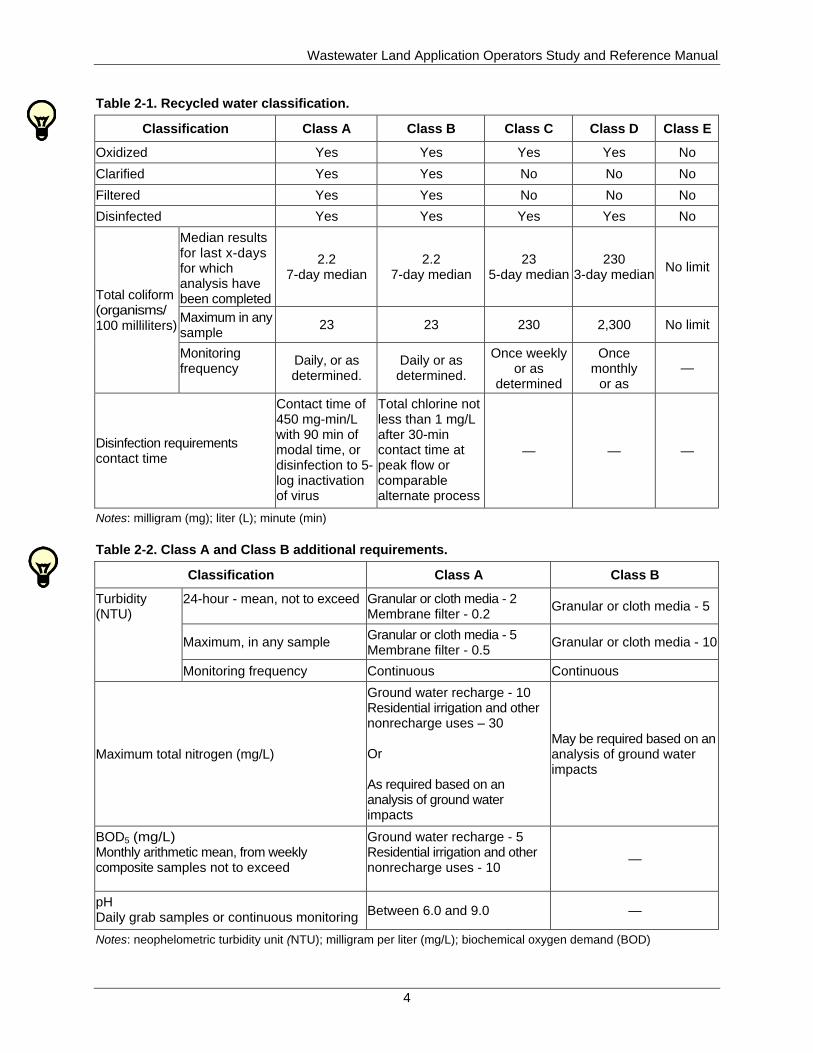
Table 2-1. Recycled water classification.
Classification Class A Class B Class C Class D Class E
Oxidized Yes Yes Yes Yes No
Clarified Yes Yes No No No
Filtered Yes Yes No No No
Disinfected Yes Yes Yes Yes No
Total coliform (organisms/ 100 milliliters)
Median results for last x-days for which analysis have been completed
2.2 7-day median
2.2 7-day median
23 5-day median
230 3-day median
No limit
Maximum in any sample
23 23 230 2,300 No limit
Monitoring frequency
Daily, or as determined.
Daily or as determined.
Once weekly or as
determined
Once monthly
or as determined
—
Disinfection requirements contact time
Contact time of 450 mg-min/L with 90 min of modal time, or disinfection to 5- log inactivation of virus
Total chlorine not less than 1 mg/L after 30-min contact time at peak flow or comparable alternate process
— — —
Notes: milligram (mg); liter (L); minute (min)
Table 2-2. Class A and Class B additional requirements.
Classification Class A Class B
Turbidity (NTU)
24-hour - mean, not to exceed Granular or cloth media - 2 Membrane filter - 0.2
Granular or cloth media - 5
Maximum, in any sample Granular or cloth media - 5 Membrane filter - 0.5
Granular or cloth media - 10
Monitoring frequency Continuous Continuous
Maximum total nitrogen (mg/L)
Ground water recharge - 10 Residential irrigation and other nonrecharge uses – 30 Or As required based on an analysis of ground water impacts
May be required based on an analysis of ground water impacts
BOD5 (mg/L) Monthly arithmetic mean, from weekly composite samples not to exceed
Ground water recharge - 5 Residential irrigation and other nonrecharge uses - 10
—
pH Daily grab samples or continuous monitoring
Between 6.0 and 9.0 —
Notes: neophelometric turbidity unit (NTU); milligram per liter (mg/L); biochemical oxygen demand (BOD)
Wastewater Land Application Operators Study and Reference Manual
5
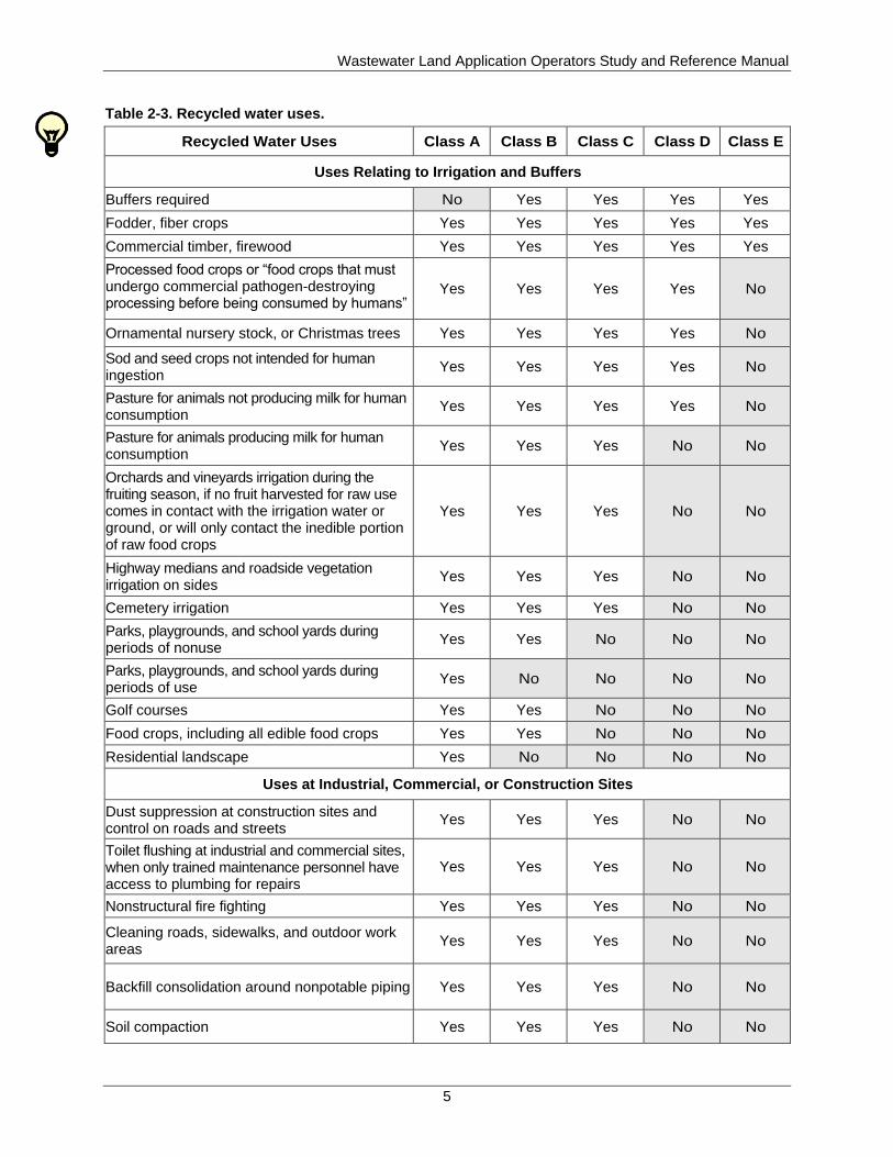
Table 2-3. Recycled water uses.
Recycled Water Uses Class A Class B Class C Class D Class E
Uses Relating to Irrigation and Buffers
Buffers required No Yes Yes Yes Yes
Fodder, fiber crops Yes Yes Yes Yes Yes
Commercial timber, firewood Yes Yes Yes Yes Yes
Processed food crops or “food crops that must undergo commercial pathogen-destroying processing before being consumed by humans”
Yes Yes Yes Yes No
Ornamental nursery stock, or Christmas trees Yes Yes Yes Yes No
Sod and seed crops not intended for human ingestion
Yes Yes Yes Yes No
Pasture for animals not producing milk for human consumption
Yes Yes Yes Yes No
Pasture for animals producing milk for human consumption
Yes Yes Yes No No
Orchards and vineyards irrigation during the fruiting season, if no fruit harvested for raw use comes in contact with the irrigation water or ground, or will only contact the inedible portion of raw food crops
Yes Yes Yes No No
Highway medians and roadside vegetation irrigation on sides
Yes Yes Yes No No
Cemetery irrigation Yes Yes Yes No No
Parks, playgrounds, and school yards during periods of nonuse
Yes Yes No No No
Parks, playgrounds, and school yards during periods of use
Yes No No No No
Golf courses Yes Yes No No No
Food crops, including all edible food crops Yes Yes No No No
Residential landscape Yes No No No No
Uses at Industrial, Commercial, or Construction Sites
Dust suppression at construction sites and control on roads and streets
Yes Yes Yes No No
Toilet flushing at industrial and commercial sites, when only trained maintenance personnel have access to plumbing for repairs
Yes Yes Yes No No
Nonstructural fire fighting Yes Yes Yes No No
Cleaning roads, sidewalks, and outdoor work areas
Yes Yes Yes No No
Backfill consolidation around nonpotable piping Yes Yes Yes No No
Soil compaction Yes Yes Yes No No
Wastewater Land Application Operators Study and Reference Manual
6
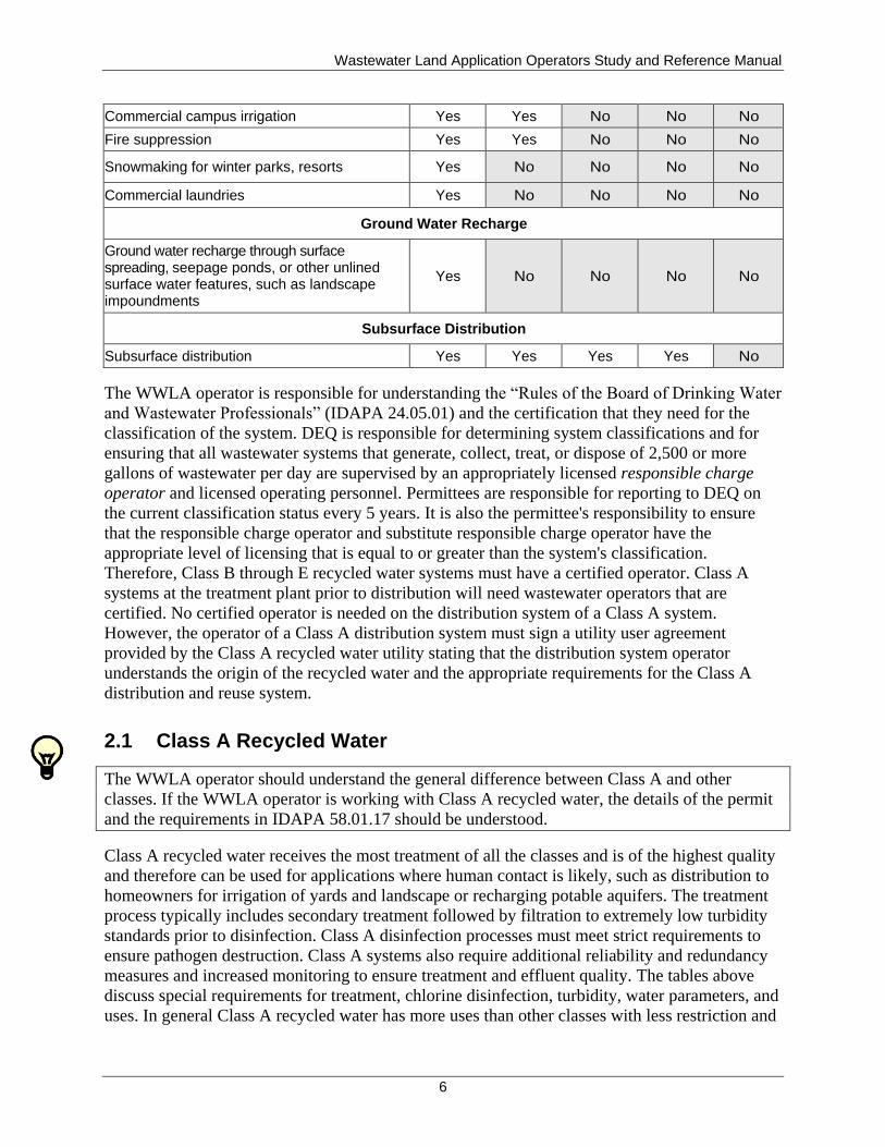
Commercial campus irrigation Yes Yes No No No
Fire suppression Yes Yes No No No
Snowmaking for winter parks, resorts Yes No No No No
Commercial laundries Yes No No No No
Ground Water Recharge
Ground water recharge through surface spreading, seepage ponds, or other unlined surface water features, such as landscape impoundments
Yes No No No No
Subsurface Distribution
Subsurface distribution Yes Yes Yes Yes No
The WWLA operator is responsible for understanding the “Rules of the Board of Drinking Water
and Wastewater Professionals” (IDAPA 24.05.01) and the certification that they need for the
classification of the system. DEQ is responsible for determining system classifications and for
ensuring that all wastewater systems that generate, collect, treat, or dispose of 2,500 or more
gallons of wastewater per day are supervised by an appropriately licensed responsible charge
operator and licensed operating personnel. Permittees are responsible for reporting to DEQ on
the current classification status every 5 years. It is also the permittee's responsibility to ensure
that the responsible charge operator and substitute responsible charge operator have the
appropriate level of licensing that is equal to or greater than the system's classification.
Therefore, Class B through E recycled water systems must have a certified operator. Class A
systems at the treatment plant prior to distribution will need wastewater operators that are
certified. No certified operator is needed on the distribution system of a Class A system.
However, the operator of a Class A distribution system must sign a utility user agreement
provided by the Class A recycled water utility stating that the distribution system operator
understands the origin of the recycled water and the appropriate requirements for the Class A
distribution and reuse system.
2.1 Class A Recycled Water
The WWLA operator should understand the general difference between Class A and other
classes. If the WWLA operator is working with Class A recycled water, the details of the permit
and the requirements in IDAPA 58.01.17 should be understood.
Class A recycled water receives the most treatment of all the classes and is of the highest quality
and therefore can be used for applications where human contact is likely, such as distribution to
homeowners for irrigation of yards and landscape or recharging potable aquifers. The treatment
process typically includes secondary treatment followed by filtration to extremely low turbidity
standards prior to disinfection. Class A disinfection processes must meet strict requirements to
ensure pathogen destruction. Class A systems also require additional reliability and redundancy
measures and increased monitoring to ensure treatment and effluent quality. The tables above
discuss special requirements for treatment, chlorine disinfection, turbidity, water parameters, and
uses. In general Class A recycled water has more uses than other classes with less restriction and
Wastewater Land Application Operators Study and Reference Manual
7
in some cases no restriction at all (such as no buffer zones). This section reviews other
requirements found in IDAPA 58.01.17.
For disinfection, Class A recycled water can be disinfected using chlorine, ozone,
ultraviolet (UV) radiation, and other alternative methods. When other methods for
chlorine disinfection are used, the permit will define the requirements. It is recommended
that Class A recycled water also is disinfected following storage.
Sampling and analysis of Class A recycled water are defined in the permit. Generally
there are daily requirements for disinfection sampling. For example, the effluent must be
sampled and analyzed daily for total coliform during periods of application.
Turbidity requirements shall be met prior to disinfection, and continuous in-line
monitoring shall occur as described in IDAPA 58.01.17.
For filtration systems using sand or other granular media or cloth media, the daily
arithmetic mean of all measurements of turbidity shall not exceed 2 neophelometric
turbidity units (NTU), and turbidity shall not exceed 5 NTU at any time.
For filtration systems using membrane filtration, the daily arithmetic mean of all
measurements of turbidity shall not exceed 0.2 NTU, and turbidity shall not exceed
0.5 NTU at any time.
Nitrogen, pH, and 5-day biochemical oxygen demand (BOD5) requirements
Total nitrogen at the point of compliance shall not exceed 10 milligrams per liter
(mg/L) for ground water recharge systems and 30 mg/L for residential irrigation and
other non-recharge uses.
The pH as determined by daily grab samples or continuous monitoring shall be
between 6.0 and 9.0.
BOD5 shall not exceed 5 mg/L for ground water recharge systems, and 10 mg/L for
residential irrigation and other non-recharge systems, based on a monthly arithmetic
mean as determined from weekly composite sampling.
Reliability and redundancy requirements are required for monitoring, equipment (i.e.,
pumps), and treatment trains and are specified in IDAPA 58.01.17 and the “Wastewater
Rules” (IDAPA 58.01.16). Standby power sufficient to maintain all treatment and
distribution works shall be required for the Class A systems as described in the rules.
Class A effluent identification is required, and all new buried pipe, including service
lines, valves, and other appurtenances, shall be colored purple (Pantone 512) or
equivalent. If fading or discoloration of the purple pipe is experienced during
construction, identification tape or locating wire along the pipe is required. Label piping
every 10 feet with “Caution: Recycled Water - Do Not Drink” or equivalent signage in
both Spanish and English. If identification tape is installed along with the purple pipe, it
shall be prepared with white or black printing on a purple field, Pantone 512, or
equivalent, with the words, “Caution: Recycled Water - Do Not Drink” or equivalent
signage in both Spanish and English. The overall width of the tape shall be at least
3 inches. Identification tape shall be installed 18 inches above the transmission pipe
longitudinally, shall be centered over the pipe, and shall run continuously along the
length of the pipe.
Existing water lines that are being converted to use with Class A effluent shall first be
accurately located and comply with leak test standards in accordance with the
American Water Works Association Standards and in coordination with DEQ. The
Wastewater Land Application Operators Study and Reference Manual
8
pipeline must be physically disconnected from any potable water lines and brought
into compliance with current state cross-connection rules and requirements in
accordance with “Idaho Rules for Public Drinking Water Systems” (IDAPA
58.01.08.543), and must meet minimum separation requirements (IDAPA
58.01.08.542.07). If the existing lines meet approval of the water supplier and DEQ
based upon the requirements set forth in IDAPA 58.01.17.607.02.b, the lines shall be
approved for Class A effluent distribution. If regulatory compliance of the system
(accurate location and verification of no cross connections) cannot be verified with
record drawings, televising, or otherwise, the lines shall be uncovered, inspected, and
identified prior to use. All accessible portions of the system must be retrofitted to
meet the requirements of these rules. After conversion of the water or irrigation line
to a recycled water effluent line, the lines shall be marked as stated in IDAPA
58.01.17.607.02.b.
All valve covers shall be of non-interchangeable shape with locking potable water
covers and shall have an inscription cast on the top surface stating “Recycled Water.”
Valve boxes shall meet the requirements of IDAPA 58.01.17.603.01a.iii. All
aboveground pipes and pumps shall be consistently color-coded purple (Pantone 512)
and marked to differentiate Class A effluent facilities from potable water facilities.
All exposed and aboveground piping, risers, fittings, pumps, and valves shall be
color-coded purple (Pantone 512) or equivalent. In addition, all piping shall be
identified using an accepted means of labeling, reading “Caution: Recycled Water -
Do Not Drink” or equivalent signage in both Spanish and English. In a fenced pump
station area, signs shall be posted on the fence on all sides.
Warning labels shall be installed on designated facilities such as, but not limited to,
controller panels and wash-down or blow-off hydrants on water trucks, hose bibs, and
temporary construction services. The labels shall read, “Caution: Recycled Water -
Do Not Drink” or equivalent signage in both Spanish and English.
Where class A recycled water is stored or impounded, or used for irrigation in public
areas, warning signs shall be installed and contain, at a minimum, 1-inch purple
letters (Pantone 512 or equivalent) on a white or other high contrast background
notifying the public that the water is unsafe to drink. Signs may also have a purple
background with white or other high contrast lettering. Warning signs and labels shall
read, “Caution: Recycled Water - Do Not Drink” or equivalent signage in both
Spanish and English.
2.2 Class B Recycled Water
The WWLA operator should understand the general difference between Class B and other
classes. If the WWLA operator is working with Class B recycled water, the details of the permit
and requirements in IDAPA 58.01.17 should be understood.
Class B recycled water is the second most treated of all the classes and the second highest in
quality. It requires treatment similar to Class A systems. The notable differences are reduced
turbidity requirements following filtration and less extreme disinfection requirements. Class B
has many uses, but it cannot be distributed to homeowners for residential irrigation or used for
ground water recharge. It can be used to irrigate all types of crops, including edible food crops.
Wastewater Land Application Operators Study and Reference Manual
9
Class B systems have reduced reliability and redundancy requirements in comparison to Class A
systems. Table 2-1, Table 2-2, and Table 2-3 discuss special requirements for treatment, chlorine
disinfection, turbidity, water parameters, and uses. Operator requirements for the treatment and
distribution system are required. This section reviews other requirements found in IDAPA
58.01.17.
For disinfection, Class B recycled water can be disinfected using chlorine, ozone, UV
radiation, and other alternative methods. When other methods for disinfection are used,
the permit will define the requirements. It is recommended that Class B recycled water
also be disinfected following storage.
Sampling and analysis of Class B recycled water are defined in the permit. Generally
there are daily requirements for disinfection sampling. The point of compliance for Class
B recycled water for total coliform shall be at any point in the system following final
treatment and disinfection contact time. For example, the effluent must be sampled and
analyzed daily for total coliform during periods of application. The sampling frequency
for Class B and Class A is similar.
Turbidity requirements shall be met prior to disinfection and continuous in-line
monitoring shall occur as described in IDAPA 58.01.17.
The daily arithmetic mean of all the measurements of turbidity shall not exceed
5 NTU and shall not exceed 10 NTU at any time.
The turbidity shall be met prior to disinfection.
Periods of use—Class B recycled water shall be applied only during periods of nonuse by
the public.
2.3 Class C Recycled Water
The WWLA operator should understand the general difference between Class C and other
classes. If the WWLA operator is working with Class C recycled water, the details of the permit,
requirements in IDAPA 58.01.017, and site-specific issues relating to health and safety should be
understood.
Class C recycled water systems are generally secondary treatment (oxidation) and disinfection.
Filtration is not a requirement of Class C systems. Disinfection requirements are less stringent
than Class A and B, and as a result the allowable uses are reduced. For example, it can be used to
irrigate fodder crops, processed food crops (food crops that undergo commercial pathogen
destroying processes), and some types of orchards. Class C is the most common type of
municipal reuse system in Idaho. Table 2-1, Table 2-2, and Table 2-3 discuss special
requirements for treatment, chlorine disinfection, and uses. Operator requirements for the
treatment and distribution system are required. This section reviews other requirements found in
IDAPA 58.01.17.
For disinfection, Class C recycled water can be disinfected using chlorine, ozone, UV
radiation, and other alternative methods. When other methods for disinfection are used,
the permit will define the requirements. It is recommended that Class C recycled water is
disinfected following storage.
Sampling and analysis of Class C recycled water are defined in the permit. Generally
there are weekly requirements for disinfection sampling. The point of compliance for
Wastewater Land Application Operators Study and Reference Manual
10
Class C recycled water for total coliform shall be at any point in the system following
final treatment and disinfection contact time. For example, the effluent must be sampled
and analyzed weekly for total coliform during periods of application.
2.4 Class D Recycled Water
The WWLA operator should understand the general difference between Class D and other
classes. If the WWLA operator is working with Class D recycled water, the details of the permit,
requirements in IDAPA 58.01.17, and site-specific issues relating to health and safely should be
understood.
Class D recycled water is similar to Class C as it requires oxidation and disinfection. The
primary difference in treatment between Class C and Class D is the disinfection requirements are
an order of magnitude lower for Class D recycled water. As a result, the allowable uses are more
limited than Class C. Irrigation of fodder, processed food crops, and forests are allowed uses of
Class D recycled water. Table 2-1, Table 2-2, and Table 2-3 discuss special requirements for
treatment, chlorine disinfection, and uses. Operator requirements for the treatment and
distribution system are required. This section reviews other requirements found in IDAPA
58.01.17.
For disinfection, Class D recycled water is disinfected to a lower level than the other
classes by using chlorine, or another alternative method. When other methods for
disinfection are used, the permit will define the requirements.
Sampling and analysis of Class D recycled water are defined in the permit. Generally
there are monthly requirements for disinfection sampling. The point of compliance for
Class D recycled water for total coliform shall be at any point in the system following
final treatment and disinfection contact time. For example, the effluent must be sampled
and analyzed monthly for total coliform during periods of application.
2.5 Class E Recycled Water
The WWLA operator should understand the general difference between Class E and other
classes. If the WWLA operator is working with Class E recycled water, the details of the permit,
requirements in IDAPA 58.01.17, and site-specific issues relating to health and safety should be
understood.
Class E recycled water requires primary treatment only (no disinfection). Allowable uses of
Class E are very limited due to the high potential pathogen content remaining in the recycled
water. Table 2-1, Table 2-2, and Table 2-3 discuss special requirements. Operator requirements
for the treatment and distribution system are required. This section reviews other requirements
found in IDAPA 58.01.17.
For disinfection, there are no disinfection requirements or applicable coliform standards
for Class E recycled water.
Sampling and analysis of Class E recycled water are not generally required unless there
are buffer zone issues that are defined in the permit.
Wastewater Land Application Operators Study and Reference Manual
11
Public access is restricted with Class E recycled water, and animals shall not be pastured
or grazed on land where Class E municipal wastewater is applied.
2.6 Industrial Recycled Water
The WWLA operator should understand the general difference between the classes of municipal
recycled water and that industrial recycled water is not classified. If the WWLA operator is
working with industrial recycled water, the details of the permit, requirements in IDAPA
58.01.17, and site-specific issues relating to use, health, and safety should be understood. The
permit requirements are determined on a case-by-case basis and developed for each industrial
site.

Wastewater Land Application Operators Study and Reference Manual
12
This page intentionally left blank for correct double-sided printing.
Wastewater Land Application Operators Study and Reference Manual
13
3 Reuse Permit Template
Need-to-Know Criteria
Facility information
Compliance activities and compliance schedules
Reuse permit limits and conditions
Reuse permit monitoring requirements
Reporting requirements
Standard permit conditions
General permit conditions
Site maps
The WWLA operator must understand the site’s reuse permit. Appendix A contains generic
examples of reuse permits. The generic examples reflect the differences between municipal and
industrial permits. Some of the differences between municipal and industrial permits include the
following:
Municipal Permits
Technical, financial, and managerial requirements
Operator certification requirements
Approved backflow assemblies or an air gap are required between potable water supplies
and all nonpotable water supplies
Divided into recycled water classes
Specific infrastructure requirements depending on the class of recycled water
Require lagoon seepage testing every 10 years
Industrial Permits
Do not have technical, financial, and managerial requirements
Generally do not have operator certification requirements
Do not require approved backflow assemblies but typically require backflow devices
Are not divided into recycled water classes
Require lagoon seepage testing on a case-by-case basis based on site-specific issues and
water characteristics.
May contain limits and conditions to address the specific characteristics of the industrial
recycled water
3.1 Facility Information
The facility information has the permit type, recycled water class, and treatment method. The
WWLA operator should understand the facility information. The WWLA operator should ensure
that the facility information in the permit is correct, notify the permittee if it is not correct, and
inform the permittee to update the permit details with DEQ. Only DEQ is authorized to make
Wastewater Land Application Operators Study and Reference Manual
14
changes to the reuse permit requirements. The permittee is responsible for complying with all
permit conditions and may be held liable for violation of permit conditions.
3.2 Compliance Activities and Compliance Schedules
The compliance activities and schedules are facility specific requirements of the permit and must
be completed as stated in the permit. The WWLA operator should understand the compliance
activities and schedules in the permit and keep the permittee informed as necessary. Failure to
comply with the requirements could result in the facility being subject to enforcement action.
Examples of a compliance activity would be the PO, solids management, runoff management,
and lagoon seepage testing plans. Such plans are required to be submitted by specific dates and
require DEQ approval prior to implementation. The quality assurance project plan (QAPP) is
also an example of a compliance activity that is self-implementing and required to be in place by
a certain date; it is reviewed by DEQ for content, but this plan is not approved by DEQ.
3.3 Reuse Permit Limits and Conditions
All permit limits and conditions must be followed.
3.3.1 Management Unit Descriptions
A management unit (MU) is a portion of the land application site that is permitted to receive
recycled water. The amount of recycled water each MU receives is referred to in the permit as
the hydraulic-loading rate. Each land application site typically consists of more than one MU.
The WWLA operator must be familiar with each of the permitted MUs and the associated limits
and conditions. Each MU may have different loading rates and management practices (e.g.,
unique irrigation and cropping practices).
Each MU has associated monitoring serial numbers—MU-XYZ-##: management unit serial
number.
Other typical monitoring point serial numbers are as follows:
SU-XYZ-##: soil monitoring unit serial number
WW-XYZ-##: wastewater monitoring serial number
SW-XYZ-##: supplemental irrigation water monitoring serial number
GW-XYZ-##: ground water monitoring serial number
LG-XYZ-##: lagoon monitoring serial number
FM-XYZ-##: flow measurement monitoring serial number
The associated reuse permit number designation is XYZ, and the ## is a two-digit designation for
each monitoring point.
3.3.2 Hydraulic-Loading Limits
The WWLA operator will need to manage MUs based upon growing season and nongrowing
season hydraulic-loading limits of the permit for each MU.
Wastewater Land Application Operators Study and Reference Manual
15
3.3.3 Constituent-Loading Limits
The WWLA operator will also need to manage MUs based upon the constituent loading so that
permit limits are met and adverse impacts to soil and ground water are minimized. The recycled
water constituents determine the loading that can be applied to each MU, and most often the
limiting constituent is nitrogen. Constituents are further discussed in section 3.4.1.
3.3.4 Management Unit Buffer Zones
The WWLA operator will also need to manage the site for compliance with buffer zone
requirements. Deficiencies should be reported to the permittee for correction. The site-specific
details are in the permit and in the “Recycled Water Rules” (IDAPA 58.01.17).
3.3.5 Other Permit Limits and Conditions
The WWLA operator will also need to read the permit to learn about other limits and conditions
applied to the site, including operator certification requirements, growing and nongrowing
season time frames, reporting time frames for the annual report, coliform limits (applicable to
municipal systems), crop or vegetation allowed, grazing (grazing requires a management plan,
preapproved by DEQ), fencing, posting, and construction plan and specification requirements.
3.4 Reuse Permit Monitoring Requirements
In support of the agency’s mission, DEQ is dedicated to using and providing objective, correct,
reliable, and understandable information. Decisions made by DEQ are subject to public review
and may, at times, be subject to rigorous scrutiny. It is, therefore, DEQ’s goal to ensure that all
decisions are based on data of known and acceptable quality. Monitoring points are specified in
the reuse permit, and monitoring must be done according to the permit. To ensure that data and
results will be of the appropriate quality, the QAPP should be referenced when taking any
samples. The QAPP should be used in conjunction with the site’s PO. WWLA operators taking
monitoring samples should ensure that a QAPP has been developed for all monitoring and
sampling and that the QAPP is followed. WWLA operators may contact the DEQ regional office
for compliance assistance with monitoring and sampling.
Note
Failure to carry out any or all of these activities or comply with the terms and conditions of the permit is a violation of Idaho law and may subject the permittee to enforcement action and/or a civil penalty assessment.
3.4.1 Constituent Monitoring
Constituent monitoring is required in both municipal and industrial permits, and each permit will
be unique for the site-specific issues. Table 3-1 is provided below to show how constituent
monitoring requirements are listed in each permit. Each monitoring point sample location along
with the associated serial number is listed in the first column. A detailed sample description is
shown in column two with the sample type and frequency shown in column three. The actual
constituents to be sampled at each monitoring point are listed in column four. For example,
Table 3-1 shows recycled water from lagoon ABC at the pump no. 1 sampling port with serial
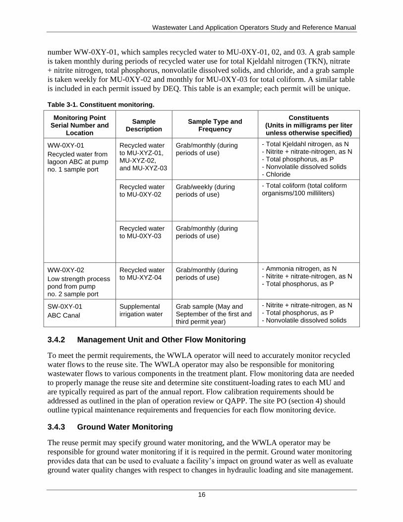
Wastewater Land Application Operators Study and Reference Manual
16
number WW-0XY-01, which samples recycled water to MU-0XY-01, 02, and 03. A grab sample
is taken monthly during periods of recycled water use for total Kjeldahl nitrogen (TKN), nitrate
+ nitrite nitrogen, total phosphorus, nonvolatile dissolved solids, and chloride, and a grab sample
is taken weekly for MU-0XY-02 and monthly for MU-0XY-03 for total coliform. A similar table
is included in each permit issued by DEQ. This table is an example; each permit will be unique.
Table 3-1. Constituent monitoring.
Monitoring Point Serial Number and
Location
Sample Description
Sample Type and Frequency
Constituents (Units in milligrams per liter unless otherwise specified)
WW-0XY-01
Recycled water from lagoon ABC at pump no. 1 sample port
Recycled water to MU-XYZ-01, MU-XYZ-02, and MU-XYZ-03
Grab/monthly (during periods of use)
- Total Kjeldahl nitrogen, as N - Nitrite + nitrate-nitrogen, as N - Total phosphorus, as P - Nonvolatile dissolved solids - Chloride
Recycled water to MU-0XY-02
Grab/weekly (during periods of use)
- Total coliform (total coliform organisms/100 milliliters)
Recycled water to MU-0XY-03
Grab/monthly (during periods of use)
WW-0XY-02
Low strength process pond from pump no. 2 sample port
Recycled water to MU-XYZ-04
Grab/monthly (during periods of use)
- Ammonia nitrogen, as N - Nitrite + nitrate-nitrogen, as N - Total phosphorus, as P
SW-0XY-01
ABC Canal
Supplemental irrigation water
Grab sample (May and September of the first and third permit year)
- Nitrite + nitrate-nitrogen, as N - Total phosphorus, as P - Nonvolatile dissolved solids
3.4.2 Management Unit and Other Flow Monitoring
To meet the permit requirements, the WWLA operator will need to accurately monitor recycled
water flows to the reuse site. The WWLA operator may also be responsible for monitoring
wastewater flows to various components in the treatment plant. Flow monitoring data are needed
to properly manage the reuse site and determine site constituent-loading rates to each MU and
are typically required as part of the annual report. Flow calibration requirements should be
addressed as outlined in the plan of operation review or QAPP. The site PO (section 4) should
outline typical maintenance requirements and frequencies for each flow monitoring device.
3.4.3 Ground Water Monitoring
The reuse permit may specify ground water monitoring, and the WWLA operator may be
responsible for ground water monitoring if it is required in the permit. Ground water monitoring
provides data that can be used to evaluate a facility’s impact on ground water as well as evaluate
ground water quality changes with respect to changes in hydraulic loading and site management.

Wastewater Land Application Operators Study and Reference Manual
17
The site QAPP should outline the ground water sampling procedures for each monitoring well.
The WWLA operator should also be familiar with well construction enough to understand or
recognize any construction deficiencies or well component degradation that may result in ground
water contamination or impact ground water quality (Appendix B). For example, improper seal,
damaged casing, or improper berming. The WWLA operator should clearly communicate to the
permittee and responsible agencies the well names, locations, and conditions along with
monitoring needs as specified in the reuse permit. The WWLA operator should also understand
which wells are upgradient and downgradient from the application site.
3.4.4 Soil Monitoring
The WWLA operator may be responsible for soil sampling at each MU as designated by the soil
monitoring unit (SU) in the permit. The site QAPP should outline the soil sampling for each SU.
Section 6 of this manual further discusses soil. The WWLA operator should know the boundaries
of each SU (typically the same boundaries as the MU) and understand any variations between
each SU in the permit.
3.4.5 Plant Tissue Monitoring
Plant tissues reflect the health and nutrient uptake of the crop. The WWLA operator may be
responsible for taking samples and ensuring that crop yields and tissue samples are recorded.
Section 6.7 of this manual further discusses agronomy and nutrient uptake.
3.4.6 Lagoon Information
Lagoons are often a unit process in wastewater treatment or provide storage for recycled water.
Seepage testing of each lagoon is often a permit requirement or required by rule. Seepage testing
requirements are specified in new permits. Older permits may not include the requirements and
DEQ should be consulted if there are questions regarding testing. Section 9 of this manual
further discusses lagoons, lagoon construction, and seepage testing. The WWLA operator should
also be familiar with lagoon construction requirements to recognize any construction deficiencies
or lagoon component degradation that may result in increased lagoon seepage or any life and
safety issues regarding the integrity of the lagoon embankments.
3.5 Reporting Requirements
The reuse permit will define the reporting requirements. All data collected need to be submitted
to DEQ in the annual report; however, the minimum reporting is specified in the reuse permit. At
minimum, records must be retained for the length of permit plus 2 years.
3.5.1 Annual Reports Requirements
The annual report is a narrative summary that discusses data collected during the year and
documents the facility’s permit compliance to DEQ. The annual report shall be prepared by a
competent environmental professional who is familiar with the permitted facility and can use the
monitoring data to describe the site conditions as they apply to the land application treatment of
the recycled water.
Wastewater Land Application Operators Study and Reference Manual
18
The WWLA operator should know what data are being monitored and collected for the annual
report based upon the permit. The WWLA operator should also know and understand why the
data are being monitored and collected to help understand, evaluate, and operate the system to
maintain compliance. The annual report is a permit requirement with due dates and required
content that is submitted to DEQ in written form. The permit outlines the information that should
be submitted in the site-specific annual report. Appendix C provides recommendations of details
to include in the annual report.
Yearly, the facility must submit an annual report, prepared by a competent environmental
professional, no later than January 31 of each year (unless otherwise specified in the reuse
permit), covering the previous reporting year, typically November 1 through October 31. The
annual report includes results of required monitoring, the status of any compliance activities
specified in the permit, and an interpretive discussion of monitoring data and public complaints,
with particular respect to environmental impacts by the facility. All laboratory reports containing
the sample results for required monitoring and other site-specific data are also submitted with the
annual report.
Annual report submittals shall include a certification statement, which is signed, dated, and
certified by the permittee’s responsible official or an authorized person representing the
responsible official. Refer to your reuse permit for the certification statement language and the
responsibilities it requires.
3.5.2 Emergency and Noncompliance Reporting
The WWLA operator needs to know the reporting requirements of the permit and communicate
them to the permittee. The permittee is required to report all noncompliance incidents to the
applicable DEQ regional office according to the standard permit conditions, which state that all
noncompliance events must be reported orally to DEQ within 24 hours and in writing within
5 days with an action plan for correcting the violation. For emergencies, the WWLA operator is
required to call the 24-hour emergency number and the appropriate DEQ regional office.
All instances of unpermitted wastewater discharges to surface waters of the United States shall
also be reported to EPA by telephone within 24 hours from the time the permittee becomes
aware of the discharge and in writing within 5 days to the following address:
National Pollutant Discharge Elimination System/
Stormwater Coordinator, EPA Idaho Operations Office
950 W. Bannock, Suite 900
Boise, ID 83702
(208) 378-5746 or (208) 378-5744 and EPA Hotline: (206) 553-1846
3.6 Permit for Use of Industrial Water
Permit for use of industrial water contains the requirements specific to industrial facilities. This
section will be marked reserved on municipal permits.
Wastewater Land Application Operators Study and Reference Manual
19
3.7 Standard Permit Conditions
Standard conditions are specified in every reuse permit. The permittee is responsible for
complying with the permit, and the WWLA operator is expected to know and follow these
conditions. An important condition is how and when emergencies and noncompliance issues are
dealt with and reported by the facility to DEQ.
3.8 General Permit Conditions
General permit conditions cover those DEQ rules that apply to the permit at the time the permit
was issued. These conditions cover operations and administrative rules that the WWLA operator
needs to know.
3.8.1 Operations
These conditions cover the rules associated with facility operations, including backflow
prevention, preventing runoff of recycled water, health hazards, nuisances, and odor prohibitions,
solids management, temporary cessation of operations and closure, PO, seepage testing
requirements (will be marked as reserved for industrial permits), and ground water quality. The
WWLA operator is expected to know and follow these conditions.
3.8.2 Administrative
These conditions cover the rules associated with the administrative portion of the facility,
including permit modifications, permit transfer, permit revocation, violations, and severability.
The WWLA operator should know and follow these conditions.
3.9 Other Applicable Laws
Other applicable laws or rules that are not enforced by DEQ may be applicable. For example, the
Idaho Department of Water Resources has rules that are applicable to all ground water wells
located at the reuse facility. These rules include well use, maintenance, repair, and abandonment.
3.10 Site Maps
Site maps are a part of each permit and help the WWLA operator and others unfamiliar with the
site orient themselves with critical elements of the site. Site maps also help the WWLA operator
in locating potential problems and explaining to DEQ and others where possible noncompliance
problems exist on site, and allow off-site personnel the needed information to solve problems in
a timely manner. These maps include regional and facility maps.

Wastewater Land Application Operators Study and Reference Manual
20
This page intentionally left blank for correct double-sided printing.
Wastewater Land Application Operators Study and Reference Manual
21
4 Permit Required Documents—Plans
Need-to-Know Criteria
Plan of operations
Quality assurance project plan
4.1 Plan of Operations
A PO, which includes the O&M manual and various permit-required facility plans, functions as a
site-specific guide for day-to-day operations of a land application site. A facility’s PO must
contain all system components relating to the reuse facility in order to comply with IDAPA
58.01.16. The reuse permit and PO should be used together in the day-to-day operations of the
reuse facility to direct the operation, maintenance, and reporting activities at the land application
site. The O&M manual portion of the PO contains the physical components and operations at the
facility and must meet the requirements of IDAPA 58.01.17.300.05, and the specific contents of
the Reuse Permit. The permit required facility plans portion of the PO contains the
administrative and sampling requirements for the nonphysical operations conducted at the
facility. The associated sampling requirements are further controlled by a facility QAPP. The
WWLA operator should be familiar with the QAPP so that permit required sampling is reliable
and reproducible. The reuse permit will require a QAPP and associated facility plans.
Figure 4-1 shows the relationship between the PO, O&M manual, various facility plans, and
QAPP.

Wastewater Land Application Operators Study and Reference Manual
22
Figure 4-1. Relationship between the PO, O&M manual, various facility plans, and QAPP.
Wastewater Land Application Operators Study and Reference Manual
23
A PO checklist in DEQ guidance lists the minimum information that shall be incorporated into
the document. A partial list of items in the PO checklist is given below.
Organizational chart and operator and manager responsibilities.
Copy of the reuse permit and a list applicable rules, statutes, and standards.
Facility maps.
General plant description—Treatment design criteria, wastewater characterization, and
list of unit operations.
O&M manual—Each facility shall maintain an O&M manual contained within the PO
specific to that facility. The O&M manual shall be developed and used as an operator
guide for actual day-to-day operations to meet requirements of the facility’s reuse permit.
Description, operation, and control of unit operations—Description of process, major
components and mechanical equipment, discussion of common operating problems and
start-up procedures, and equipment operating instructions with reference to equipment
O&M manual.
Wastewater and recycled water storage lagoons—Description and purpose, capacity,
operating instructions, and seepage rate testing requirements.
Reuse site features, buffer zone delineations, fencing and postings, backflow prevention,
climatic characteristics, soils, topography, surface water, ground water, description of
irrigation systems and operating instructions, and determination of hydraulic- and
constituent-loading rates.
Vegetation—Describe crops or vegetation that will be used on each reuse site.
Management plans for buffer zones, grazing, controlling nuisance conditions, waste
solids, runoff/run-on, and others as required by the reuse permit.
Monitoring activities and requirements.
Maintenance—Preventative maintenance schedule, troubleshooting guides, and
manufacturer’s manuals.
Records and reports—Daily operating log, maintenance records, laboratory records, and
reports, and reporting permit violations and accidents.
Personnel—Staffing requirements and qualifications.
Emergency operating plan—Emergency numbers and emergency procedures.
All system components should have specification sheets, showing details of the units as well as
operation and maintenance requirements. These are usually included in the O&M manual or
attached as a supplement. If this information is not present, the WWLA operator should contact
the manufacturers directly.
Typically, equipment will have a specification plate with the company name, location, and
component model or serial number. Manufacturer information on servicing the equipment should
be found in the O&M manual. If the manufacturer is no longer in business, a local repair service
may be able to provide service or information. If no information is available, service units
similar to other units with like components.
Specific management plans, in addition to information provided in the facility O&M manual,
may be required per the facility reuse permit. Some example plans and important aspects of each
are presented below.
Wastewater Land Application Operators Study and Reference Manual
24
Grazing management plan—DEQ guidance specifies under what circumstances livestock
grazing on land application sites is allowed. Prior to any grazing activities, a grazing
management plan must be submitted to DEQ for review and approval. Items typically
addressed in a grazing management plan include specifying the type and number of
animals to be grazed, identifying the schedule for rotating animals through the site,
preparing a nutrient balance, identifying the disinfection level of the applied recycled
water, and identifying the minimum waiting periods prior to grazing animals on sites
irrigated with recycled water.
Odor management plan—An odor management plan addresses all wastewater treatment
systems, land application facilities, and other operations associated with the facility. The
plan includes specific design considerations, operation and maintenance procedures, and
management practices to be employed to minimize the potential for or limit odors. The
plan also includes procedures to respond to an odor incident, if one occurs, including
notification procedures.
Waste solids management plan—This plan describes how waste solids generated at the
facility, including dredgings and sludges, are handled and disposed of in a manner
specific to the rules the different wastes may need to follow. The reuse permit will
discuss the differences between the waste solids and rules that may apply. The waste
solids management plan prevents waste entry, or the entry of contaminated drainage or
leachate into the waters of the state, so that health hazards and nuisance conditions are
not created, and impacts to designated beneficial uses of the ground water and surface
water are prevented.
Emergency action plans—Emergency action plans cover various situations that may
occur such as transportation spills, site runoff, power outages, major equipment failure,
and bomb threats. (A detailed discussion of emergency action plans is presented in
section 13.6.1).
4.2 Quality Assurance Project Plan
A QAPP is a written document outlining the procedures that the reuse sites use to ensure the data
it collects and analyzes meet permit requirements.
Quality data and information constitute the foundation of informed decision making, and a
QAPP ensures that the data collected by monitoring projects are of known and suitable quality
and quantity. The QAPP summarizes the data quality objectives of the project and integrates all
technical and quality aspects—including planning, implementation, and assessment—into a
single document. For example procedures used for collecting and evaluating different monitoring
parameters should be included in the QAPP. The WWLA operator should consult the QAPP
every time they are sampling.
In support of the agency mission, DEQ is dedicated to using and providing objective, correct,
reliable, and understandable information. Decisions made by DEQ are subject to public review
and may, at times, be subject to rigorous scrutiny. It is, therefore, DEQ’s goal to ensure that all
decisions are based on data of known and acceptable quality. A QAPP must be submitted to
DEQ as a stand-alone document for review and acceptance to assist in planning for the
collection, analysis, and reporting of all monitoring data in support of the reuse permit and in
explaining data anomalies when they occur. DEQ does not approve QAPPs but reviews them to

Wastewater Land Application Operators Study and Reference Manual
25
determine if the minimum EPA guideline requirements are met and that the reuse facility permit
requirements are satisfied. The reason DEQ does not approve QAPPs is that the responsibility
for validation of the facility sampling data lies with the permit holder and DEQ’s responsibility
is not to validate this information as an on-site quality assurance officer.
The format of the QAPP should adhere to the recommendations and references in the Quality
Assurance and Data Processing sections of the DEQ guidance. QAPPs developed using the DEQ
guidance should also agree in substance with EPA’s QAPPs. Copies of the associated EPA
guidance documents and example QAPPs can be downloaded or printed from the following
website: http://www.epa.gov/quality/qapps.html.

Wastewater Land Application Operators Study and Reference Manual
26
This page intentionally left blank for correct double-sided printing.
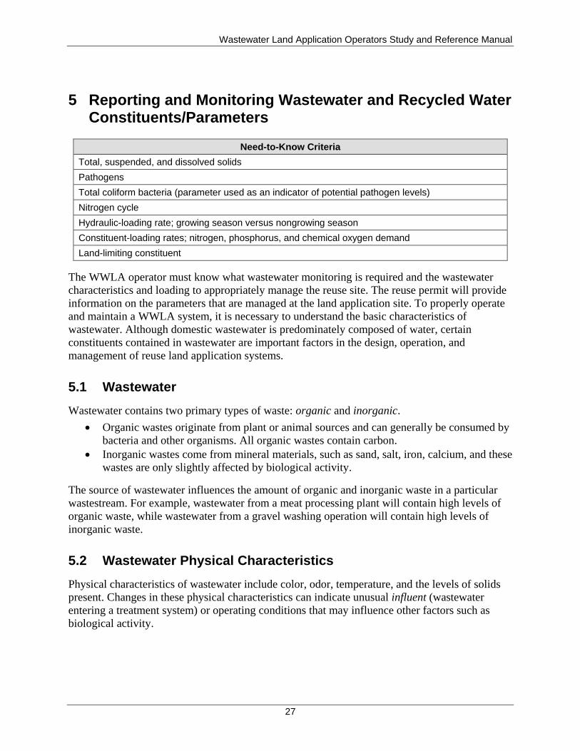
Wastewater Land Application Operators Study and Reference Manual
27
5 Reporting and Monitoring Wastewater and Recycled Water Constituents/Parameters
Need-to-Know Criteria
Total, suspended, and dissolved solids
Pathogens
Total coliform bacteria (parameter used as an indicator of potential pathogen levels)
Nitrogen cycle
Hydraulic-loading rate; growing season versus nongrowing season
Constituent-loading rates; nitrogen, phosphorus, and chemical oxygen demand
Land-limiting constituent
The WWLA operator must know what wastewater monitoring is required and the wastewater
characteristics and loading to appropriately manage the reuse site. The reuse permit will provide
information on the parameters that are managed at the land application site. To properly operate
and maintain a WWLA system, it is necessary to understand the basic characteristics of
wastewater. Although domestic wastewater is predominately composed of water, certain
constituents contained in wastewater are important factors in the design, operation, and
management of reuse land application systems.
5.1 Wastewater
Wastewater contains two primary types of waste: organic and inorganic.
Organic wastes originate from plant or animal sources and can generally be consumed by
bacteria and other organisms. All organic wastes contain carbon.
Inorganic wastes come from mineral materials, such as sand, salt, iron, calcium, and these
wastes are only slightly affected by biological activity.
The source of wastewater influences the amount of organic and inorganic waste in a particular
wastestream. For example, wastewater from a meat processing plant will contain high levels of
organic waste, while wastewater from a gravel washing operation will contain high levels of
inorganic waste.
5.2 Wastewater Physical Characteristics
Physical characteristics of wastewater include color, odor, temperature, and the levels of solids
present. Changes in these physical characteristics can indicate unusual influent (wastewater
entering a treatment system) or operating conditions that may influence other factors such as
biological activity.
Wastewater Land Application Operators Study and Reference Manual
28
5.2.1 Color
Raw municipal wastewater (prior to any treatment) is usually gray in color. Pretreated
wastewater will have a color that indicates the pretreatment system; wastewater treated in a
septic tank will have a gray-black color, but wastewater that has been treated in an aerobic
process will have little color. The color of wastewater can also be affected by industrial
contributions to the treatment system; color contributed by industry typically is not removed by
the pretreatment system. Operators should be aware of such colors depending upon the type of
facility being managed. Changes to the water coloration typical of the facility may need
investigation.
5.2.2 Odor
Raw municipal wastewater usually produces a musty odor, generally caused by the anaerobic
decomposition of organic material. Hydrogen sulfide is frequently the source of a rotten-egg
odor in wastewater and can be a public health concern at relatively low concentrations. Other
volatile sulfur-containing compounds, such as mercaptans, can also cause noxious odors. These
odors are released into the air when wastewater is aerated and sometimes when the wastewater is
discharged to a land application site. As a point of reference, mercaptans are added to natural gas
to impart a detectable odor for leak detection and safety purposes.
Other or unexpected odors, such as petroleum or solvent odors, may indicate abnormal industrial
discharges. Operators should be aware of such odors depending upon the type of facility being
managed. Changes to the odors typical of the facility may need investigation.
5.2.3 Temperature
Wastewater is generally somewhat warmer than tap water. Noticeable increases or decreases in
wastewater temperature may indicate influence from other sources such as industrial discharge,
stormwater, or ground water infiltration.
Temperature is an important factor in microbial activity. Up to a point, an increase in wastewater
temperature will increase microbial activity. However, when wastewater reaches high
temperatures, microbial activity will be inhibited.
During land application of recycled water, high water temperatures can also adversely impact
crops. Operators should be aware of temperature variations depending upon the type of facility
being managed. Changes to the temperatures typical of the facility may need investigation.
5.2.4 Solids
One of the primary functions of a wastewater treatment system is the removal of solids. Solids
can reduce the effectiveness of wastewater disinfection systems and clog land application
equipment.
Determining the forms and concentrations of solids present in wastewater provides useful
information for the control of treatment processes. Solids are divided into several different
fractions, as shown in Figure 5-1. The individual fractions are determined through specific
laboratory analysis.
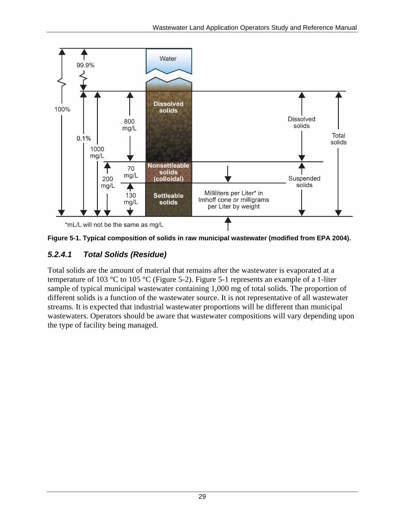
Wastewater Land Application Operators Study and Reference Manual
29
Figure 5-1. Typical composition of solids in raw municipal wastewater (modified from EPA 2004).
5.2.4.1 Total Solids (Residue)
Total solids are the amount of material that remains after the wastewater is evaporated at a
temperature of 103 °C to 105 °C (Figure 5-2). Figure 5-1 represents an example of a 1-liter
sample of typical municipal wastewater containing 1,000 mg of total solids. The proportion of
different solids is a function of the wastewater source. It is not representative of all wastewater
streams. It is expected that industrial wastewater proportions will be different than municipal
wastewaters. Operators should be aware that wastewater compositions will vary depending upon
the type of facility being managed.
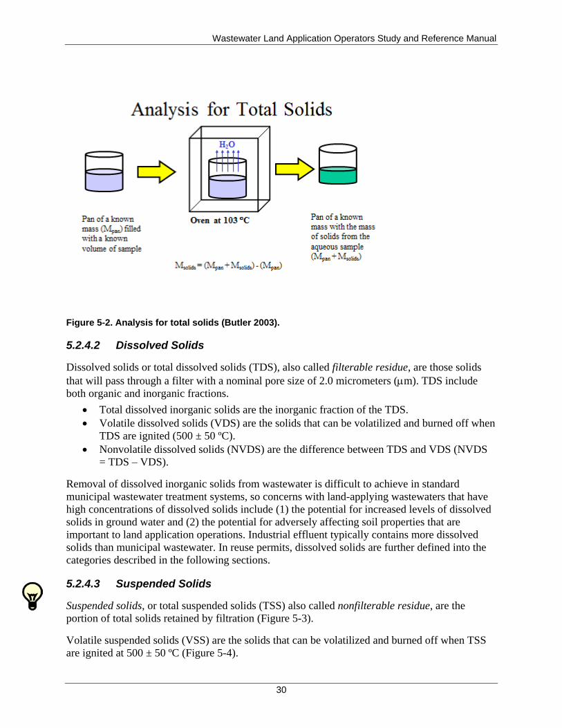
Wastewater Land Application Operators Study and Reference Manual
30
Figure 5-2. Analysis for total solids (Butler 2003).
5.2.4.2 Dissolved Solids
Dissolved solids or total dissolved solids (TDS), also called filterable residue, are those solids
that will pass through a filter with a nominal pore size of 2.0 micrometers (m). TDS include
both organic and inorganic fractions.
Total dissolved inorganic solids are the inorganic fraction of the TDS.
Volatile dissolved solids (VDS) are the solids that can be volatilized and burned off when
TDS are ignited (500 ± 50 ºC).
Nonvolatile dissolved solids (NVDS) are the difference between TDS and VDS (NVDS
= TDS – VDS).
Removal of dissolved inorganic solids from wastewater is difficult to achieve in standard
municipal wastewater treatment systems, so concerns with land-applying wastewaters that have
high concentrations of dissolved solids include (1) the potential for increased levels of dissolved
solids in ground water and (2) the potential for adversely affecting soil properties that are
important to land application operations. Industrial effluent typically contains more dissolved
solids than municipal wastewater. In reuse permits, dissolved solids are further defined into the
categories described in the following sections.
5.2.4.3 Suspended Solids
Suspended solids, or total suspended solids (TSS) also called nonfilterable residue, are the
portion of total solids retained by filtration (Figure 5-3).
Volatile suspended solids (VSS) are the solids that can be volatilized and burned off when TSS
are ignited at 500 ± 50 ºC (Figure 5-4).
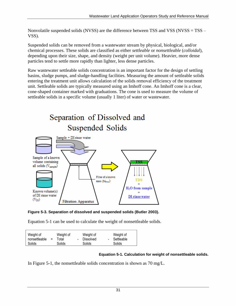
Wastewater Land Application Operators Study and Reference Manual
31
Nonvolatile suspended solids (NVSS) are the difference between TSS and VSS (NVSS = TSS –
VSS).
Suspended solids can be removed from a wastewater stream by physical, biological, and/or
chemical processes. These solids are classified as either settleable or nonsettleable (colloidal),
depending upon their size, shape, and density (weight per unit volume). Heavier, more dense
particles tend to settle more rapidly than lighter, less dense particles.
Raw wastewater settleable solids concentration is an important factor for the design of settling
basins, sludge pumps, and sludge-handling facilities. Measuring the amount of settleable solids
entering the treatment unit allows calculation of the solids removal efficiency of the treatment
unit. Settleable solids are typically measured using an Imhoff cone. An Imhoff cone is a clear,
cone-shaped container marked with graduations. The cone is used to measure the volume of
settleable solids in a specific volume (usually 1 liter) of water or wastewater.
Figure 5-3. Separation of dissolved and suspended solids (Butler 2003).
Equation 5-1 can be used to calculate the weight of nonsettleable solids.
Equation 5-1. Calculation for weight of nonsettleable solids.
In Figure 5-1, the nonsettleable solids concentration is shown as 70 mg/L.
Weight of nonsettleable Solids
= Weight of Total Solids
- Weight of Dissolved Solids
- Weight of Settleable Solids
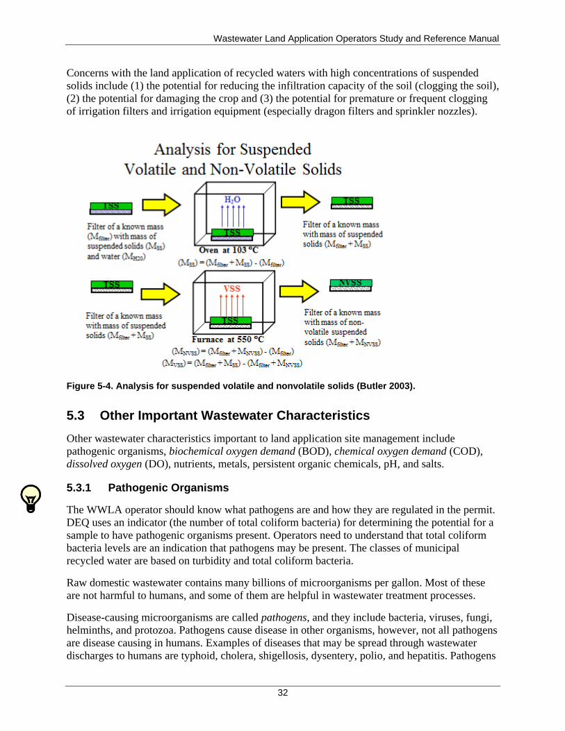
Wastewater Land Application Operators Study and Reference Manual
32
Concerns with the land application of recycled waters with high concentrations of suspended
solids include (1) the potential for reducing the infiltration capacity of the soil (clogging the soil),
(2) the potential for damaging the crop and (3) the potential for premature or frequent clogging
of irrigation filters and irrigation equipment (especially dragon filters and sprinkler nozzles).
Figure 5-4. Analysis for suspended volatile and nonvolatile solids (Butler 2003).
5.3 Other Important Wastewater Characteristics
Other wastewater characteristics important to land application site management include
pathogenic organisms, biochemical oxygen demand (BOD), chemical oxygen demand (COD),
dissolved oxygen (DO), nutrients, metals, persistent organic chemicals, pH, and salts.
5.3.1 Pathogenic Organisms
The WWLA operator should know what pathogens are and how they are regulated in the permit.
DEQ uses an indicator (the number of total coliform bacteria) for determining the potential for a
sample to have pathogenic organisms present. Operators need to understand that total coliform
bacteria levels are an indication that pathogens may be present. The classes of municipal
recycled water are based on turbidity and total coliform bacteria.
Raw domestic wastewater contains many billions of microorganisms per gallon. Most of these
are not harmful to humans, and some of them are helpful in wastewater treatment processes.
Disease-causing microorganisms are called pathogens, and they include bacteria, viruses, fungi,
helminths, and protozoa. Pathogens cause disease in other organisms, however, not all pathogens
are disease causing in humans. Examples of diseases that may be spread through wastewater
discharges to humans are typhoid, cholera, shigellosis, dysentery, polio, and hepatitis. Pathogens
Wastewater Land Application Operators Study and Reference Manual
33
can lead to disease; however, for a pathogen to cause disease, it must have a susceptible host, a
pathway of exposure, and there must be an infective dose. Without these three elements, disease
cannot occur. Wastewater treatment, reuse methods, and management practices are used to
address one or more of these elements.
Many pathogenic organisms are killed during the normal treatment processes; however,
sufficient numbers can remain in the effluent (treated wastewater leaving the treatment system)
to cause a threat to any downstream use involving human contact if adequate disinfection is not
accomplished in the treatment process.
5.3.1.1 Identification of Pathogens
It is impractical to test wastewater for all pathogens. Instead, indicator bacteria are commonly
used to identify the possible presence of pathogens.
Some bacteria commonly used as indicators are total coliform bacteria, fecal coliform, or
Escherichia coli. Total coliform bacteria are always present in the digestive systems of humans
and warm-blooded animals. If there is a large concentration of coliform bacteria present in
wastewater, the potential for the presence of pathogens is high. Total coliform bacteria are
typically reduced in number during normal wastewater treatment processes. Total coliform
bacteria are used as the primary indicator of potential pathogens in municipal recycled water in
Idaho. The reuse permit may specify total coliform or another organism as the pathogen potential
indicator.
5.3.1.2 Removal of Pathogens
Wastewater treatment processes remove pathogenic organisms in several ways: physical removal
through filtration and sedimentation, natural die-off of organisms because of unfavorable
environments, and destruction of organisms by disinfection. Disinfection processes further
reduce pathogen levels of the recycled water and the requirement for municipal recycled water is
based upon the recycled water class. (Disinfection is discussed in more detail in section 8).
5.3.2 Biochemical Oxygen Demand and Chemical Oxygen Demand
The WWLA operator should know what biochemical and chemical oxygen demand are and
understand the loading limit of the parameter on the reuse site.
BOD measures the rate that microorganisms use oxygen to stabilize or break down (oxidize) the
organic matter in wastewater biologically.
High levels of BOD indicate high levels of organic matter in wastewater. The typical
range of BOD in municipal wastewater ranges from 100 to 300 mg/L of BOD.
BOD is measured using a biochemical oxygen demand test, a procedure that measures the
amount of oxygen used by a wastewater sample incubated at 20 °C for 5 days. The
amount of organic material measured is referred to as BOD5, referring to the 5-day length
of the test.
COD measures the amount of organic matter that can be broken down (oxidized) chemically.
Wastewater Land Application Operators Study and Reference Manual
34
COD can estimate the amount of organic matter in wastewater in only 3 to 4 hours, rather
than the 5 days required for the BOD5 test and can be used as an alternative.
The COD test measures the oxygen equivalent (in milligrams per liter) of the materials
present in the wastewater by oxidizing the wastewater using a strong chemical oxidant.
Because the chemical oxidant may react with substances that cannot be broken down by
bacteria, COD results are not directly related to BOD5. However, COD can be used as a
means of rapidly estimating the BOD5 of a sample if BOD5-to-COD ratios are developed
for a particular system. COD results are typically higher than the BOD5 value when
enough oxygen is present because chemicals (COD) are stronger and can break down
(oxidize) organic matter more quickly than biological organisms (BOD). The ratio
between the two will vary from system to system. The BOD5-to-COD ratio is typically
0.6:1 for raw domestic wastewater and may drop to as low as 0.1:1 for a well-stabilized
secondary effluent.
5.3.3 Dissolved Oxygen
DO is the amount of oxygen dissolved in water and is usually expressed in milligrams per liter.
Although some microorganisms can survive in anaerobic conditions (without oxygen), many of
the beneficial microorganisms that stabilize wastewater require aerobic conditions (with
oxygen).
The amount of oxygen that can be dissolved in water depends on temperature—as water
temperature increases, DO content decreases and vice versa—and the distribution of oxygen
within a lagoon (or pond) will determine whether the treatment processes involved are aerobic or
anaerobic. Maintaining adequate oxygen levels allows the biological process to take place and
prevents objectionable odors. Low DO concentrations (less than 1.0 mg/L) can indicate
inadequate aeration or an excessive amount of organic material entering the system.
DO is measured using an oxygen meter equipped with a membrane-covered probe. Probes
require careful cleaning, and meters must be calibrated routinely to ensure accuracy.
5.3.4 Nutrients
A nutrient is any substance that promotes growth and can be taken up by plants or other
organisms. Wastewater generally contains nutrients, such as nitrogen, phosphorus, potassium,
calcium, magnesium, iron, and sulfur. In a land application system, recycled water can provide
essential nutrients to crops. If present at excessive levels, however, some nutrients can become
pollutants.
The WWLA operator should know what nutrients need to be managed on the reuse site and
understand the loading rate limitations.
5.3.4.1 Nitrogen
All life-forms require nitrogen compounds, such as proteins and nucleic acids, to survive. The
largest source of nitrogen is the air we breathe—approximately 78% of air is nitrogen gas (N2),
but most organisms cannot use nitrogen in this form. Most plants receive their nitrogen in a fixed
form (i.e., nitrate ions [NO3-], ammonia [NH3], and urea [2(NH2)CO]), and animals receive their
Wastewater Land Application Operators Study and Reference Manual
35
nitrogen from plants. There is a class of plants called legumes that use nitrogen from the air to
meet nutritional requirements. Alfalfa, one of the most common crops at reuse sites, is a legume.
The nitrogen cycle (Figure 5-5) describes the reactions that nitrogen may undergo. Nitrogen
starts as a gas (N2) in the atmosphere and is transformed into other forms of nitrogen through
nitrogen fixation. Nitrogen is fixed naturally through atmospheric fixation (by lightning) or
through biological fixation (by certain microbes living alone in the soil or in a symbiotic
relationship with plants in the legume family, such as soybeans and alfalfa, or nonlegume plants
such as alders). Nitrogen is also fixed industrially in the production of fertilizers, which consist
of ammonia, urea, and ammonium nitrate (NH4NO3). As plants and animals die, organic forms of
nitrogen are returned to the environment, where microorganisms convert the organic nitrogen to
ammonium. Much of the ammonia and ammonium produced by decay and manures are further
broken down by nitrifying bacteria into nitrite ions (NO2-) and then into nitrate ions (NO3-),
which are available to plants. The nitrogen cycle is completed when denitrifying bacteria convert
nitrate ions back into atmospheric nitrogen.
Nitrogen in wastewater occurs in four different forms: organic nitrogen, ammonia (NH3) or
ammonium (NH4+), nitrite (NO2
-), and nitrate (NO3
-). In raw wastewater, organic nitrogen and
ammonia levels are generally higher than nitrite and nitrate levels. Proteins, polypeptides,
nucleic acids and urea, and numerous synthetic organic materials in wastewater contribute to the
organic nitrogen. The nitrogen cycle reactions are important because nitrogen is a potentially
serious pollutant in wastewater, and its behavior in and benefits to a wastewater land application
system are highly dependent on which form the nitrogen is in when applied to the site.
In the nitrate form, nitrogen becomes a highly mobile anion. In this highly mobile form, when
the soil nitrogen concentration exceeds permit limits, nitrates can be beneficial or cause adverse
impacts depending on how the land application site is loaded. If the soil nitrogen concentration
exceeds the permit limits for crop uptake, the excess nitrates will be carried below the root zone
where it may adversely affect ground water quality. Therefore, the site must be operated to avoid
exceeding the permit nitrogen limits.
Total nitrogen is the sum of organic nitrogen, ammonia, nitrite, and nitrate. TKN is the sum of
organic nitrogen and ammonia. Typical ranges of nitrogen concentrations in raw domestic
wastewater are 20 to 85 mg/L for total nitrogen, 8 to 35 mg/L for organic nitrogen, and 12 to
50 mg/L for ammonia. Plant-available nitrogen (PAN) is nitrogen that exists in forms (NH4+ and
NO3-) that are readily available for uptake by plants.
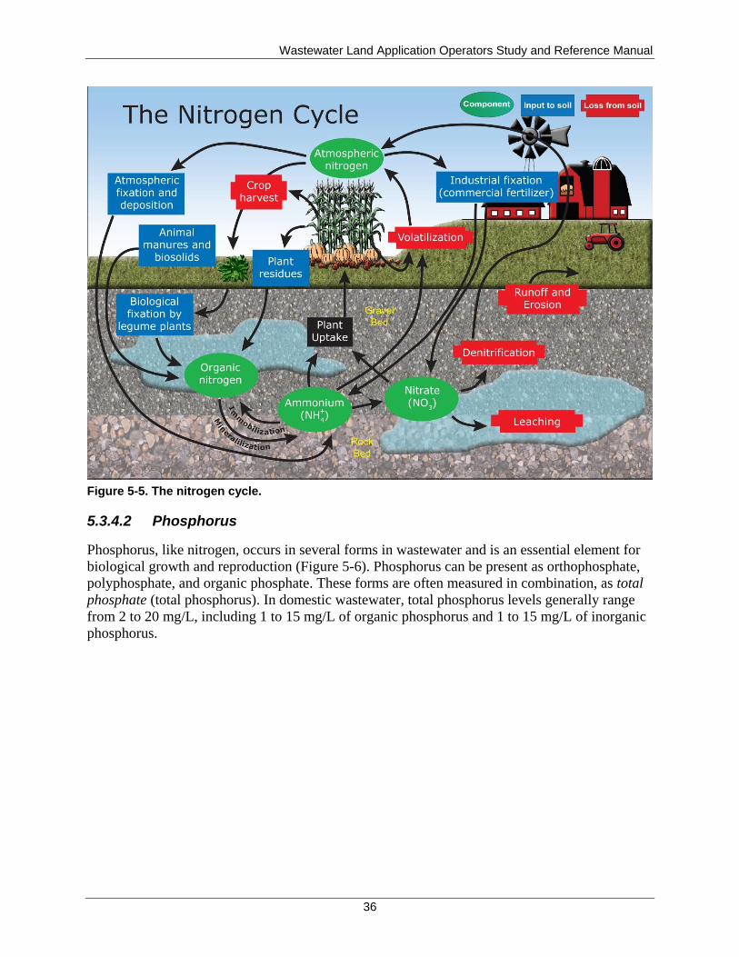
Wastewater Land Application Operators Study and Reference Manual
36
Figure 5-5. The nitrogen cycle.
5.3.4.2 Phosphorus
Phosphorus, like nitrogen, occurs in several forms in wastewater and is an essential element for
biological growth and reproduction (Figure 5-6). Phosphorus can be present as orthophosphate,
polyphosphate, and organic phosphate. These forms are often measured in combination, as total
phosphate (total phosphorus). In domestic wastewater, total phosphorus levels generally range
from 2 to 20 mg/L, including 1 to 15 mg/L of organic phosphorus and 1 to 15 mg/L of inorganic
phosphorus.
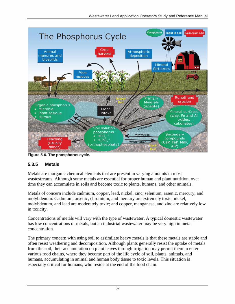
Wastewater Land Application Operators Study and Reference Manual
37
Figure 5-6. The phosphorus cycle.
5.3.5 Metals
Metals are inorganic chemical elements that are present in varying amounts in most
wastestreams. Although some metals are essential for proper human and plant nutrition, over
time they can accumulate in soils and become toxic to plants, humans, and other animals.
Metals of concern include cadmium, copper, lead, nickel, zinc, selenium, arsenic, mercury, and
molybdenum. Cadmium, arsenic, chromium, and mercury are extremely toxic; nickel,
molybdenum, and lead are moderately toxic; and copper, manganese, and zinc are relatively low
in toxicity.
Concentrations of metals will vary with the type of wastewater. A typical domestic wastewater
has low concentrations of metals, but an industrial wastewater may be very high in metal
concentration.
The primary concern with using soil to assimilate heavy metals is that these metals are stable and
often resist weathering and decomposition. Although plants generally resist the uptake of metals
from the soil, their accumulation on plant leaves through irrigation may permit them to enter
various food chains, where they become part of the life cycle of soil, plants, animals, and
humans, accumulating in animal and human body tissue to toxic levels. This situation is
especially critical for humans, who reside at the end of the food chain.
Wastewater Land Application Operators Study and Reference Manual
38
Because of the potential health effects of metals, it is necessary to properly manage land
application sites to minimize the effects of metals on human health and the environment. The
permit will specify monitoring for metals and the site is to be managed so that there is enough
land to minimize accumulation. The life expectancy of the site may be based upon the
accumulation of metals or other toxic substances.
5.3.6 Persistent Organic Chemicals
Although microorganisms can readily decompose most organic wastes, some organic chemicals
are not readily biodegradable and can persist in water and soil for many years. These persistent
organic chemicals can reach the soil in many ways. They are sometimes a component of
pesticides (insecticides and herbicides), or they may be found in the wastestream that is being
treated at the land application site. Persistent organic chemicals are also found where old
underground storage tanks have leaked petroleum products into the soil.
With a municipal or domestic waste source, persistent organic chemical concentrations are likely
to be extremely low, or nonexistent. These chemicals may be present in higher concentrations,
however, in an industrial waste source. Like metals, persistent organic chemicals can be toxic to
animals and humans.
5.3.7 pH
pH is the measure of the concentration of the hydrogen ions (H+) in a solution. A pH of 7 is
neutral, while a pH reading below 7 indicates acidic conditions and a pH reading above 7
indicates alkaline (basic) conditions. The pH of domestic wastewater typically ranges from 6.5
to 7.5, depending on the pH of potable water in the service system. Significant departures from
these values may indicate industrial or other nondomestic discharges.
In land application systems, bacteria may perform wastewater treatment in pretreatment units
and in the soil. These bacteria prefer a neutral pH (or 7) for best performance. Any rapid increase
or decrease in pH can cause mortality in the bacteria population, resulting in poor treatment.
Note
Acidity is the capacity of water to neutralize bases. Water does not have to be strongly acidic (low pH) to have a high acidity. Alkalinity is the capacity of water to neutralize acids. Water does not have to be strongly basic (high pH) to have a high alkalinity.
5.3.8 Salts
Chlorides, sulfates, potassium, calcium, sodium, and manganese are the most common soluble
salts (ionic compounds) that are present in wastewater. Some of the salts may be removed during
wastewater treatment. Other salts, such as ferric chloride and alum, are sometimes added to aid
in wastewater treatment.
Soluble salts, especially sodium (Na+), are important constituents of wastewater. When water
containing high levels of sodium or other salts is land applied, there may be some swelling of
clay minerals, which can reduce water movement through the soil. To reemphasize this point,
salts reduce both infiltration (at the surface) and water movement through the soil (under the
Wastewater Land Application Operators Study and Reference Manual
39
surface). This tendency occurs when the ratio of sodium to other cations (positively charged
particles) is high. This relationship is called the sodium adsorption ratio (SAR) of a wastewater
sample or soil extract. For recycled water with high levels of sodium or SAR, the soil conditions
should be routinely checked for infiltration problems (especially with heavy clay soils).
5.4 Hydraulic- and Constituent-Loading Rates
Three factors must be considered for loading rates: hydraulic-loading rate , constituent-loading
rate, and land-limiting constituent; these factors are discussed below. Other sources of water
(e.g., supplemental water) may add to the overall hydraulic- and nutrient-loading rates.
5.4.1 Hydraulic-Loading Rate
For land application systems, the hydraulic-loading rate is the combination of all water
(precipitation, recycled water, and any additional irrigation water) applied to a land application
site. Example units of measurement include gallons per acre and acre-inches. (An acre-inch is
the volume of water covering 1 acre of land to a depth of 1 inch and is equal to 27,154 gallons.)
Reuse permits specify hydraulic-loading rate limits for the growing season and nongrowing
season (NGS). A site’s growing season is identified by climatic conditions, which vary
throughout the state. Typical growing season dates are April 1 through October 31, and typical
nongrowing season dates are November 1 through March 31.
The growing season hydraulic-loading rate is typically specified to be substantially at the
irrigation water requirement (IWR) of the crop (the water requirement of the crop). The
calculation methodology for the IWR is covered in section 14.
For those permits allowing NGS land application, the NGS hydraulic-loading rate is generally
limited to that given by Equation 5-2.
Maximum (NGS) Hydraulic Loading Rate
= Available Water-Holding Capacity of the Soil
+ Evapotranspiration in the NGS
– Average Precipitation in the NGS
Equation 5-2. Calculation of maximum hydraulic-loading rate.
An important objective of a land application system is to assimilate and treat all applied recycled
water, supplemental irrigation water, and expected precipitation. The primary concerns with
hydraulic overloading at a land application site are leaching of contaminants into the ground
water and surface runoff along with a reduction in biological activity in the soil due to saturated
soil. Surface runoff causes soil erosion and has the potential to impact nearby surface waters. To
prevent runoff from a land application site, hydraulic-loading rates should not exceed the soil
infiltration rate.
For sites that land apply during the NGS, it is particularly critical in winter months to not exceed
the soil infiltration rate to prevent leaching of contaminants below the root zone and to prevent
runoff from the site that may be accelerated due to freezing conditions and ice buildup. During
the growing season, the health of the crop may be adversely affected with either excessively high
or low hydraulic-loading rates. Hydraulic-loading rates above permit rates must be avoided to
Wastewater Land Application Operators Study and Reference Manual
40
prevent leaching of contaminants to the ground water and runoff. Contact the DEQ regional
office if hydraulic loadings above permit limits are needed to avoid lagoon overtopping or other
emergencies.
5.4.2 Constituent-Loading Rates
The loading rates of constituents are important operating factors at a land application site.
Constituents that are typically evaluated include nitrogen, phosphorus, NVDS (salts), and COD.
The loading rates for nitrogen, phosphorus, NVDS, and COD are defined as the rate at which
these constituents are applied to the site. Loading rates for nitrogen, phosphorus, and NVDS are
generally given in pounds per acre. The COD loading rate is generally evaluated as an average
daily loading rate (pounds per acre per day) during the growing season and nongrowing season.
5.4.2.1 Nitrogen
The assimilative capacity for nitrogen (N) is an important part of a land application treatment
system because it may be a health concern if it leaches to ground water and violates permit
requirements. Nitrogen removal can be very efficient in a soil-crop system. Efforts must be
made, however, to control the leaching and runoff losses of nitrogen compounds. Conditions of
rapid water movement beyond the root zone, which can occur with excess water application to
soils, can lead to leaching and increased nitrate levels in ground water; approaches to mitigating
such effects include the following:
The basic approach to reduce leaching is to have crops that use nitrogen at the rate
applied. This approach will help prevent excess nitrate accumulation and potential
leaching problems and subsequent ground water pollution.
The basic approach in controlling runoff is to apply runoff control technologies including
hydraulic-loading rates not exceeding the soil infiltration rate, uniform sprinkler
application, and using runoff control structures, such as berms and ponds.
If nongrowing season application is allowed, the goal is to retain the nitrogen applied in
the soil column and make it available for crop uptake the following growing season.
5.4.2.2 Phosphorus
Phosphorus (P) is a required crop nutrient. It is also a major contributor of pollution to streams,
causing algae blooms, low DO, undesirable plant growth, and fish kills. Phosphorus can reach
streams by runoff from land application sites or by inflow from aquifer recharge of the stream
(ground water/surface water interconnection); mitigation strategies include the following:
To protect surface waters from the effects of excess phosphorus, surface runoff and deep
percolation of phosphorus must be controlled.
Surface runoff concerns may be prevented or mitigated by applying runoff control
technologies.
Phosphorus impacts to surface water from deep percolation and ground water
interconnections may be prevented or mitigated by managing the phosphorus-loading rate
and phosphorus accumulation in the soil.
Wastewater Land Application Operators Study and Reference Manual
41
5.4.2.3 Chemical Oxygen Demand
COD is a common measure of organic matter being land applied. Most reuse permits in Idaho
have a maximum COD loading rate of 50 lb/acre-day, averaged over the growing season. If
nongrowing season application is allowed, the COD loading rate is normally limited to
50 lb/acre-day or less. Soils are a good medium for the assimilation of the organic matter in
wastewater. Excessive COD loadings, however, can limit infiltration as a result of soil clogging,
create anaerobic conditions, and reduce the site’s ability to treat recycled water. Clogging
generally occurs in the top few inches of soil and reduces water infiltration rates and can lead to
higher runoff rates. Anaerobic conditions reduce aerobic treatment processes and may cause odor
problems.
5.4.3 Land-Limiting Constituent
Wastewater from most domestic and commercial sources contains low concentrations of
nitrogen, phosphorus, COD, and other constituents, such as TDS. For these wastewater streams,
the amount of recycled water that can be applied to a treatment site is typically limited by the
hydraulic-loading rate (hydraulically limited), based on crop water requirements.
With higher strength wastewaters, however, the amount of applied water may be limited by the
amount of nitrogen, phosphorus, NVDS, or COD, for example, in the recycled waterstream. This
land-limiting constituent then dictates the amount of recycled water that may be land applied. In
these cases, sites typically use supplemental irrigation water to ensure the crop is receiving
adequate moisture for crop health.

Wastewater Land Application Operators Study and Reference Manual
42
This page intentionally left blank for correct double-sided printing.
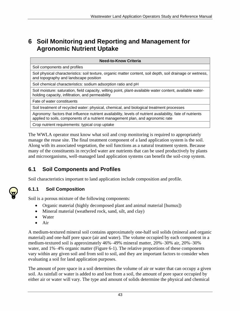
Wastewater Land Application Operators Study and Reference Manual
43
6 Soil Monitoring and Reporting and Management for Agronomic Nutrient Uptake
Need-to-Know Criteria
Soil components and profiles
Soil physical characteristics: soil texture, organic matter content, soil depth, soil drainage or wetness, and topography and landscape position
Soil chemical characteristics: sodium adsorption ratio and pH
Soil moisture: saturation, field capacity, wilting point, plant-available water content, available water-holding capacity, infiltration, and permeability
Fate of water constituents
Soil treatment of recycled water: physical, chemical, and biological treatment processes
Agronomy: factors that influence nutrient availability, levels of nutrient availability, fate of nutrients applied to soils, components of a nutrient management plan, and agronomic rate
Crop nutrient requirements: typical crop uptake
The WWLA operator must know what soil and crop monitoring is required to appropriately
manage the reuse site. The final treatment component of a land application system is the soil.
Along with its associated vegetation, the soil functions as a natural treatment system. Because
many of the constituents in recycled water are nutrients that can be used productively by plants
and microorganisms, well-managed land application systems can benefit the soil-crop system.
6.1 Soil Components and Profiles
Soil characteristics important to land application include composition and profile.
6.1.1 Soil Composition
Soil is a porous mixture of the following components:
Organic material (highly decomposed plant and animal material [humus])
Mineral material (weathered rock, sand, silt, and clay)
Water
Air
A medium-textured mineral soil contains approximately one-half soil solids (mineral and organic
material) and one-half pore space (air and water). The volume occupied by each component in a
medium-textured soil is approximately 46%–49% mineral matter, 20%–30% air, 20%–30%
water, and 1%–4% organic matter (Figure 6-1). The relative proportions of these components
vary within any given soil and from soil to soil, and they are important factors to consider when
evaluating a soil for land application purposes.
The amount of pore space in a soil determines the volume of air or water that can occupy a given
soil. As rainfall or water is added to and lost from a soil, the amount of pore space occupied by
either air or water will vary. The type and amount of solids determine the physical and chemical
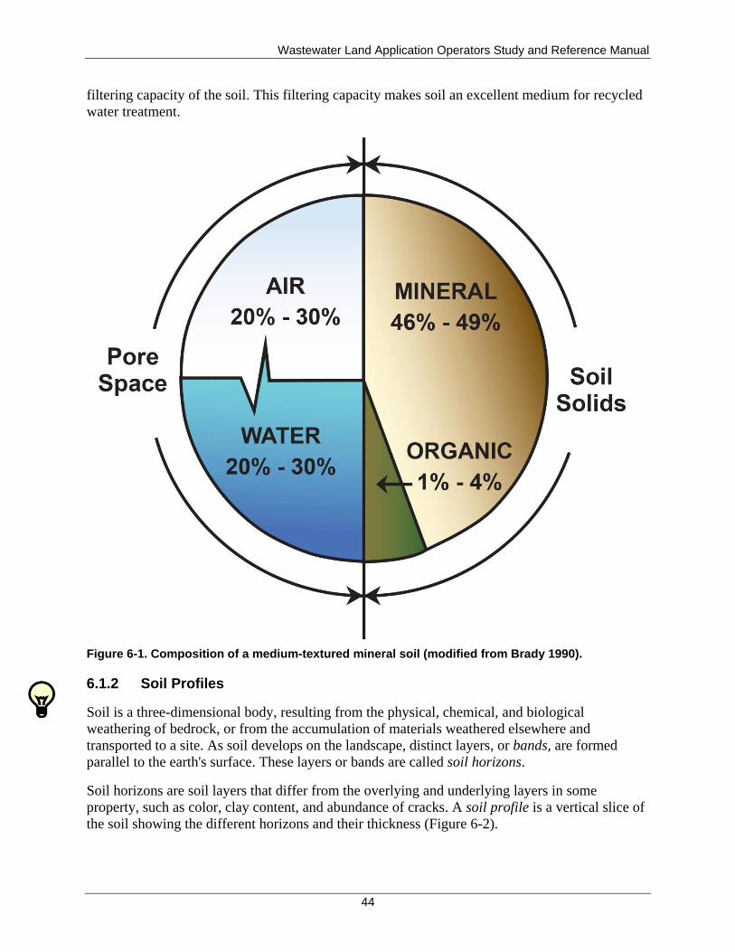
Wastewater Land Application Operators Study and Reference Manual
44
filtering capacity of the soil. This filtering capacity makes soil an excellent medium for recycled
water treatment.
Figure 6-1. Composition of a medium-textured mineral soil (modified from Brady 1990).
6.1.2 Soil Profiles
Soil is a three-dimensional body, resulting from the physical, chemical, and biological
weathering of bedrock, or from the accumulation of materials weathered elsewhere and
transported to a site. As soil develops on the landscape, distinct layers, or bands, are formed
parallel to the earth's surface. These layers or bands are called soil horizons.
Soil horizons are soil layers that differ from the overlying and underlying layers in some
property, such as color, clay content, and abundance of cracks. A soil profile is a vertical slice of
the soil showing the different horizons and their thickness (Figure 6-2).
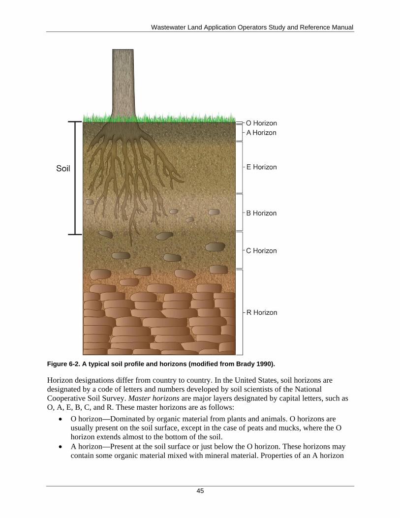
Wastewater Land Application Operators Study and Reference Manual
45
Figure 6-2. A typical soil profile and horizons (modified from Brady 1990).
Horizon designations differ from country to country. In the United States, soil horizons are
designated by a code of letters and numbers developed by soil scientists of the National
Cooperative Soil Survey. Master horizons are major layers designated by capital letters, such as
O, A, E, B, C, and R. These master horizons are as follows:
O horizon—Dominated by organic material from plants and animals. O horizons are
usually present on the soil surface, except in the case of peats and mucks, where the O
horizon extends almost to the bottom of the soil.
A horizon—Present at the soil surface or just below the O horizon. These horizons may
contain some organic material mixed with mineral material. Properties of an A horizon
Wastewater Land Application Operators Study and Reference Manual
46
may reflect plowing, pasturing, or similar activities. The A horizon is generally the zone
of maximum biological activity in a soil.
E horizon—Characterized by loss of clay, iron, and aluminum oxides from leaching; sand
and silt-sized particles of resistant minerals, such as quartz, remain. The E horizon is
generally lighter in color than the overlying A horizon.
B horizon—Exhibits layers of accumulation of clay, iron, and aluminum oxides that have
migrated from overlying E horizons. The B horizon reflects the subsurface layer of
greatest development for that particular profile.
C horizon—Consist of unconsolidated, partially weathered material that is neither rock
nor soil. Little to no biological activity takes place in this horizon. The upper portion may
become part of the B horizon as weathering continues.
R horizon—Consists of underlying bedrock. It may not occur in coastal plain soils or
other soils formed in transported material, such as floodplains.
Soil profiles with similar characteristics or properties are classified as a soil series. A soil series
includes soil that has developed from similar materials and processes, resulting in similar soil
profiles. Because soil profiles vary so widely from place to place, many different soil series have
been identified. (Approximately 17,000 soil series are found in the United States alone.) The
characteristics of the soil series present at a proposed treatment site will determine if the site is
suitable for the application of recycled water.
6.2 Soil Physical Characteristics
A number of physical soil characteristics affect water treatment at a land application site. While
some of these characteristics can be altered, others cannot. Physical characteristics include the
following:
Soil texture
Soil structure
Organic matter content
Soil depth
Soil color
Soil drainage/wetness
Topography and landscape position
6.2.1 Soil Texture
The mineral particles in a soil are divided by size into three groups: sand, silt, and clay (Figure
6-3). Soil texture refers to the relative proportion of sand, silt, and clay in a given soil. The
diameters and characteristics of these soil particles are described in Table 6-1.
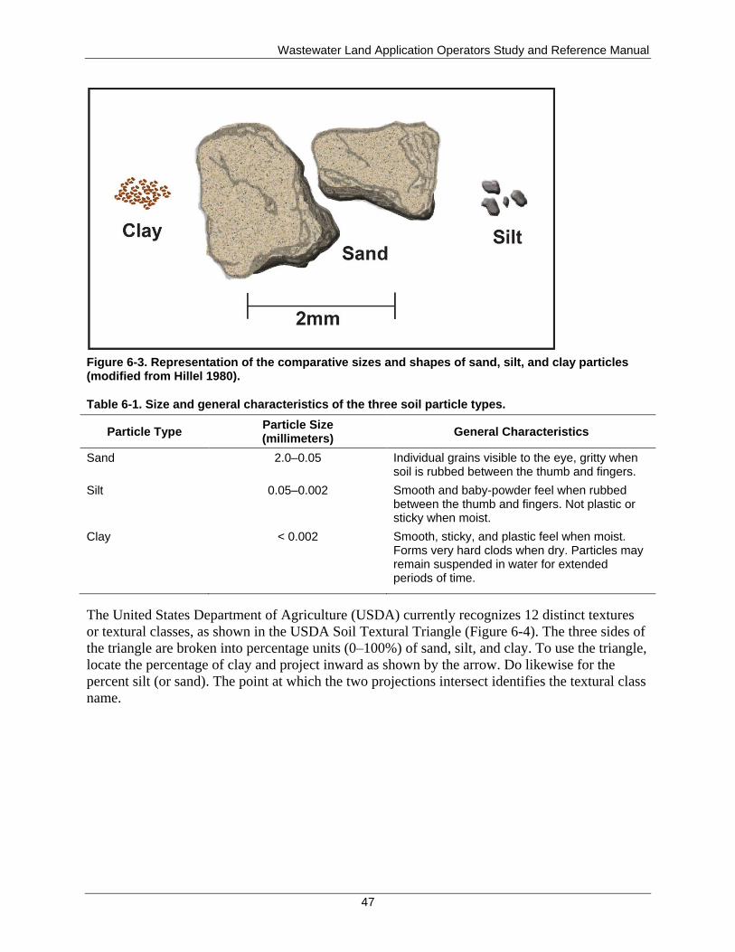
Wastewater Land Application Operators Study and Reference Manual
47
Figure 6-3. Representation of the comparative sizes and shapes of sand, silt, and clay particles (modified from Hillel 1980).
Table 6-1. Size and general characteristics of the three soil particle types.
Particle Type Particle Size (millimeters)
General Characteristics
Sand 2.0–0.05 Individual grains visible to the eye, gritty when soil is rubbed between the thumb and fingers.
Silt 0.05–0.002 Smooth and baby-powder feel when rubbed between the thumb and fingers. Not plastic or sticky when moist.
Clay < 0.002 Smooth, sticky, and plastic feel when moist. Forms very hard clods when dry. Particles may remain suspended in water for extended periods of time.
The United States Department of Agriculture (USDA) currently recognizes 12 distinct textures
or textural classes, as shown in the USDA Soil Textural Triangle (Figure 6-4). The three sides of
the triangle are broken into percentage units (0–100%) of sand, silt, and clay. To use the triangle,
locate the percentage of clay and project inward as shown by the arrow. Do likewise for the
percent silt (or sand). The point at which the two projections intersect identifies the textural class
name.
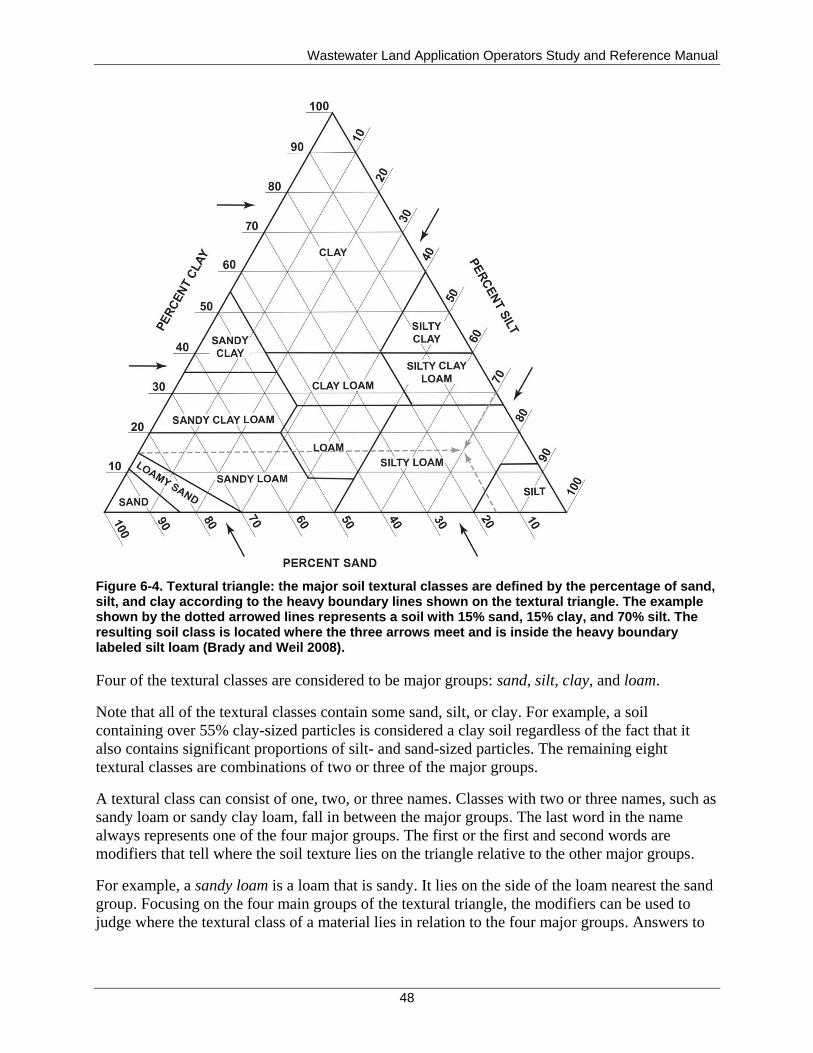
Wastewater Land Application Operators Study and Reference Manual
48
Figure 6-4. Textural triangle: the major soil textural classes are defined by the percentage of sand, silt, and clay according to the heavy boundary lines shown on the textural triangle. The example shown by the dotted arrowed lines represents a soil with 15% sand, 15% clay, and 70% silt. The resulting soil class is located where the three arrows meet and is inside the heavy boundary labeled silt loam (Brady and Weil 2008).
Four of the textural classes are considered to be major groups: sand, silt, clay, and loam.
Note that all of the textural classes contain some sand, silt, or clay. For example, a soil
containing over 55% clay-sized particles is considered a clay soil regardless of the fact that it
also contains significant proportions of silt- and sand-sized particles. The remaining eight
textural classes are combinations of two or three of the major groups.
A textural class can consist of one, two, or three names. Classes with two or three names, such as
sandy loam or sandy clay loam, fall in between the major groups. The last word in the name
always represents one of the four major groups. The first or the first and second words are
modifiers that tell where the soil texture lies on the triangle relative to the other major groups.
For example, a sandy loam is a loam that is sandy. It lies on the side of the loam nearest the sand
group. Focusing on the four main groups of the textural triangle, the modifiers can be used to
judge where the textural class of a material lies in relation to the four major groups. Answers to
Wastewater Land Application Operators Study and Reference Manual
49
questions such as "What contains more sand: a sandy loam or a loamy sand?" should then be
obvious.
Texture can be determined in a laboratory using either sieve or hydrometer analysis. Sieve
analysis is based on physical passage of soil particles through a series of standard mesh screens,
while hydrometer analysis is based on variations in settling time for the different soil particle
sizes. Texture can also be determined in the field by using the feel method (Figure 6-5).
Texture is an important soil characteristic because it strongly influences the retention of water,
nutrients, and pollutants. Coarsely textured soils, such as sands and loamy sands, have large
spaces (macropores) between their soil particles. Water and air pass through these macropores
rapidly. Therefore, coarsely textured soils are usually well-aerated and well-drained. However,
water often passes through these soils too quickly for significant treatment to occur. In addition,
these soils may not hold sufficient water and nutrients to support a healthy vegetative cover. A
poor vegetative cover can result in an increased potential for erosion and reduced uptake of
water, nutrients, and pollutants.
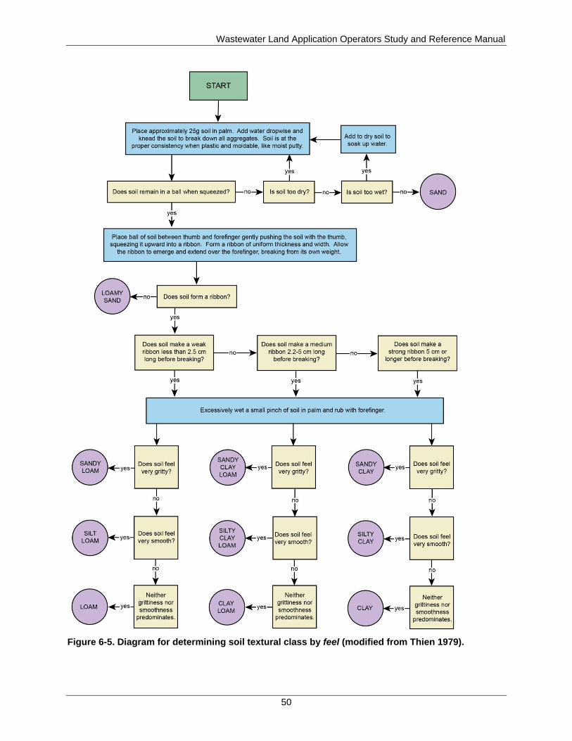
Wastewater Land Application Operators Study and Reference Manual
50
Figure 6-5. Diagram for determining soil textural class by feel (modified from Thien 1979).
Wastewater Land Application Operators Study and Reference Manual
51
Finely textured soils, such as clays, sandy clays, and silty clays have smaller spaces (micropores)
between soil particles. Due to cohesive and adhesive forces, micropores hold water, nutrients and
pollutants more tightly than macropores. Therefore, water tends to move into and through finely
textured soils more slowly. Wastewater may pond on the soil surface, causing runoff. If a sandy
soil horizon is underlain by a clayey horizon, wastewater may move into the sandy surface
horizon but not through the clayey subsoil. Water may perch on top of the clayey horizon and
move laterally, emerging downslope and causing runoff.
Therefore, when evaluating a soil for land application, the texture of all the horizons needs to be
considered. Water movement, treatment, and plant rooting patterns are often influenced by
several horizons. Many problems associated with land application can be predicted by
determining soil textures throughout the profile.
Because texture of a soil horizon is the relative proportion of sand, silt, and clay, it may be
changed only through the addition of one of these soil separates; the addition of organic matter
will not change the soil texture, but it may change the way the soil feels. However, modification
of soil texture is not practical on a large scale.
6.2.2 Soil Structure
Along with soil texture, soil structure is one of principle factors that influences the rate of water
movement. Soil structure refers to the arrangement of individual soil particles (sand, silt, and
clay) into more complex aggregates or peds. These peds can be separated from each other along
natural planes, zones, or surfaces of weakness into distinct units.
Ped units may be granular, blocky, subangular blocky, columnar, prismatic, or platy (Figure 6-6).
Soils that do not form structural units, such as very sandy soils, are considered structureless.
Soils that do not naturally separate into structural units, such as very sticky clayey soils, are
considered to have massive structure. Granular structure is often present in the A and E horizons,
while other types of structure are generally found in the lower horizons.
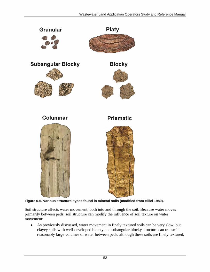
Wastewater Land Application Operators Study and Reference Manual
52
Figure 6-6. Various structural types found in mineral soils (modified from Hillel 1980).
Soil structure affects water movement, both into and through the soil. Because water moves
primarily between peds, soil structure can modify the influence of soil texture on water
movement:
As previously discussed, water movement in finely textured soils can be very slow, but
clayey soils with well-developed blocky and subangular blocky structure can transmit
reasonably large volumes of water between peds, although these soils are finely textured.
Wastewater Land Application Operators Study and Reference Manual
53
In finely textured soils with massive structure, (the clay is so sticky that individual peds
do not form); water movement can be expected to be slow and restricted. Water
movement can also be slow in soils with some platy, prismatic, or columnar structure.
Unlike texture, structure can be easily altered by management practices. Additions of organic
matter can improve soil structure by acting as a binding agent for soil particles. Unfortunately,
changes in soil structure are usually negative. If finely textured soils are traveled with heavy
equipment, tilled, or otherwise worked when wet, soil aggregates are destroyed and macropores
disappear, resulting in soil compaction. In this condition, water and air cannot move through the
soil. Even after the soil dries, structure remains destroyed. It is very important to keep heavy
equipment off of land application fields when wet to avoid compacting the soil.
6.2.3 Organic Material Contents
Soil organic matter (humus) is composed of decomposing plant and animals and waste materials
produced by soil microorganisms. The organic matter content of most mineral soils is generally
less than 4%. However, organic matter serves several important functions in soil-crop treatment
systems:
Organic matter promotes soil structure formation in finer-textured soils. Good soil
structure aids water movement in soil by increasing the pore space.
In sandy soils, organic matter helps fill larger pores and increases the soil’s ability to hold
water, nutrients, and pollutants, thus increasing its treatment potential.
Organic matter is a food source for soil microorganisms. Microbial activity, in turn,
produces waste products that promote soil structure formation.
Organic matter contains several plant nutrients, particularly nitrogen, phosphorus, and
sulfur. As organic matter decays, these nutrients become available for use by plants and
microorganisms.
Organic matter has a high negative charge, which increases a soil’s ability to retain water,
nutrients, and pollutants.
6.2.4 Soil Depth
Soil depth refers to the thickness of the soil horizons, from the soil surface to a depth that
restricts plant root growth or otherwise limits biological activity. The plant rooting depth or root
limiting depth (whichever is less) is generally used to determine the hydraulic loading limits in a
reuse permit and is also used by the operator to design and manage irrigation schedules. This
limiting depth is often caused by a restrictive horizon in the soil. A restrictive horizon could be a
seasonal or permanent water table, layer of gravel, weathered or unweathered bedrock, chemical
change, or soil structural change that limits the depth of biological activity.
Soil depth is important for the following reasons:
It determines the volume of soil that is available for the treatment of recycled water.
It affects the type of plants that can be grown on the site.
Wastewater Land Application Operators Study and Reference Manual
54
6.2.5 Soil Color
Soil color is an indicator characteristic that is used to predict soil-water relationships in a soil
profile. Soil color is an extremely useful tool when evaluating a site for suitability as a land
treatment system.
Soils that are well drained typically have rather bright colors due to oxidized or ferric iron (Fe+3
).
Ferric iron imparts a reddish/orange color to the soil. When soil drainage is impeded, and the soil
is saturated, the ferric iron contained in the soil is chemically reduced to ferrous iron (Fe+2
).
Ferrous iron is soluble in water, and as the water table recedes, this soluble iron is removed,
leaving behind soil that is gray in color.
As the water table rises and falls, a characteristic pattern called mottling usually develops.
Mottled soils generally contain bright orange and red areas mixed with light gray areas. These
mottle patterns are impressed upon the original background, or matrix color, of the soil.
The presence or absence of gray mottles or color in a soil is an indication of the wetness or
aeration status of the soil:
Bright, uniform colors indicate that a soil is well drained and that a seasonal high water
table is not present for a significant time during the year.
The presence of light grayish mottles usually indicates a high water table or poorly
drained soil. The depth to gray colors can be used to define the drainage class of a soil
and indicate the depth of the seasonal high water table.
Soils with gray mottling near the soil surface are not generally suitable for land
application because saturated soil conditions are not conducive to land treatment, may
move constituents to ground water, and may limit the type of plants and adversely impact
plant health.
Soil color is determined by using an international color standard, the Munsell system. This
standard was developed to describe colors and to avoid confusion that can arise by describing a
color as simply red or yellow. The Munsell system uses three components of color to describe
coloration within a soil—hue, value, and chroma:
Hue is the dominant spectral color (red and yellow).
Value describes the degree or darkness or lightness.
Chroma refers to the purity or strength of the color.
A moist soil sample is compared to the color chips in a Munsell color book to identify the most
appropriate match.
6.2.6 Soil Drainage/Wetness
Soil drainage or wetness refers to the depth of the water table and to the period of time a
particular part of the soil profile is saturated. A soil may be classified as well drained,
moderately well drained, somewhat poorly drained, poorly drained, or very poorly drained.
Poorly drained soils have a water table at or within 12 inches of the soil surface for most of the
year. Well-drained soils have a water table depth of 60 inches or more during much of the year.

Wastewater Land Application Operators Study and Reference Manual
55
The drainage class of a soil can usually be determined by observing both the color patterns of the
soil profile and the soil's relative position on the landscape.
Poorly drained and very poorly drained soils are not generally considered suitable for land
application for several reasons:
Wet soils do not provide adequate treatment capacity, and waste constituents may move
directly to ground water.
Seasonally wet soils may limit the type of plants that can be grown on the site and can
impact the quality of the vegetative cover.
Wet soils are subject to compaction by equipment traffic that destroys soil structure and
reduces the infiltrative capacity of a site.
The drainage class of a soil refers to water table depth, not permeability (section 6.4.3).
Consequently, although a soil might be coarsely textured and relatively easily drained, a high
water table due to landscape position can render the soil poorly drained. If an outlet or a drainage
system is provided for soil water, then this poorly drained sandy soil may be modified. However,
installing any type of drainageway or drainage system at a land application site is not
recommended because it could be a violation of the system’s permit conditions.
6.2.7 Topography and Landscape Position
Topography refers to the configuration of the land surface and is usually defined by the slope of
the land (steepness). Landscape position refers to a specific setting on the landscape. Examples
of landscape positions include the following:
Upland or ridgetop
Sideslope
Shoulder slope
Footslope
Depression
Floodplain
The topography and landscape position of a site are important because they influence the types
of soils that may be present, respective depth of those soils, and water movement characteristics
of the site. Slope considerations also dictate how a site can be managed and whether land
application is even possible. Land application is generally not acceptable on steep slopes. Fields
with more slope will require more management practices to prevent soil erosion and runoff.
Topography influences surface water removal, whereas landscape position influences ground
water flow. Topography is an important consideration when managing a site. Your specific site
dynamics as they relate to water flow should be understood; for example, steep slopes may
encourage runoff and erosion, while nearly level sites may encourage ponding or seasonal high
water tables.
Figure 6-7 shows cross-sectional and plan views of different landscape positions. In foot slope
and head slope positions, surface water converges with a corresponding increase in ground water
flow. At these positions, springs or seeps of water coming out of the ground can be expected.
Since these sites accumulate water, they are often saturated. Additional flow from wastewater
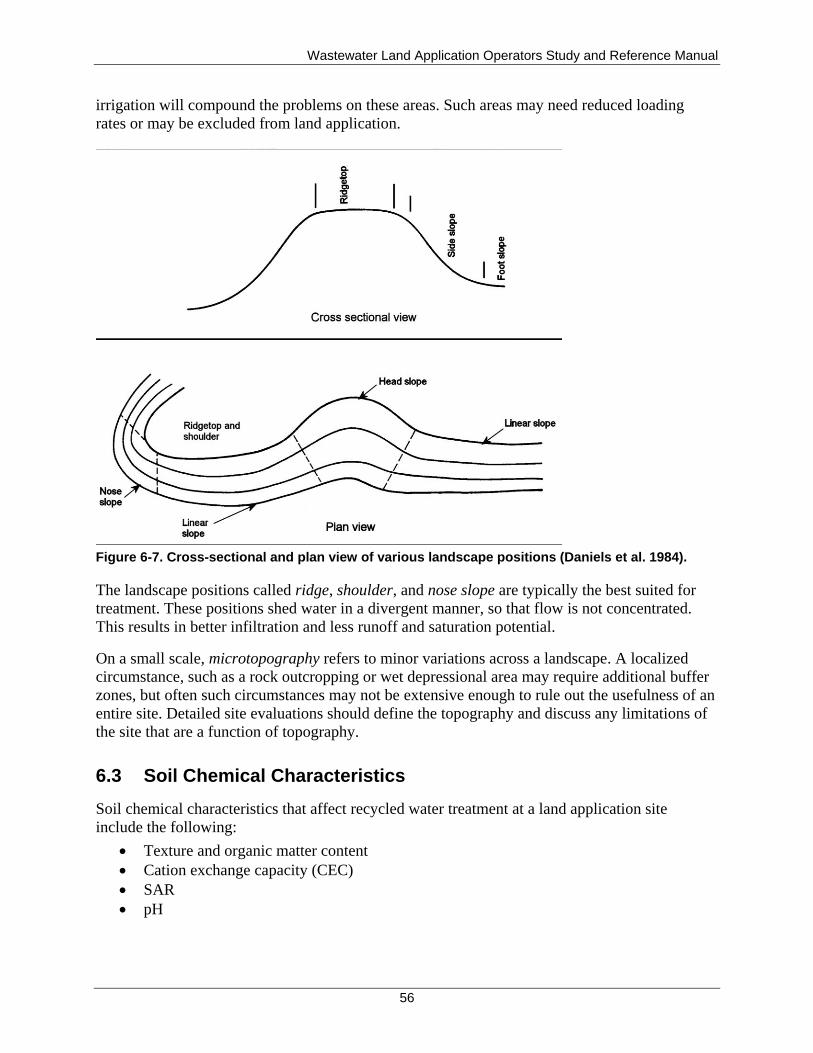
Wastewater Land Application Operators Study and Reference Manual
56
irrigation will compound the problems on these areas. Such areas may need reduced loading
rates or may be excluded from land application.
Figure 6-7. Cross-sectional and plan view of various landscape positions (Daniels et al. 1984).
The landscape positions called ridge, shoulder, and nose slope are typically the best suited for
treatment. These positions shed water in a divergent manner, so that flow is not concentrated.
This results in better infiltration and less runoff and saturation potential.
On a small scale, microtopography refers to minor variations across a landscape. A localized
circumstance, such as a rock outcropping or wet depressional area may require additional buffer
zones, but often such circumstances may not be extensive enough to rule out the usefulness of an
entire site. Detailed site evaluations should define the topography and discuss any limitations of
the site that are a function of topography.
6.3 Soil Chemical Characteristics
Soil chemical characteristics that affect recycled water treatment at a land application site
include the following:
Texture and organic matter content
Cation exchange capacity (CEC)
SAR
pH
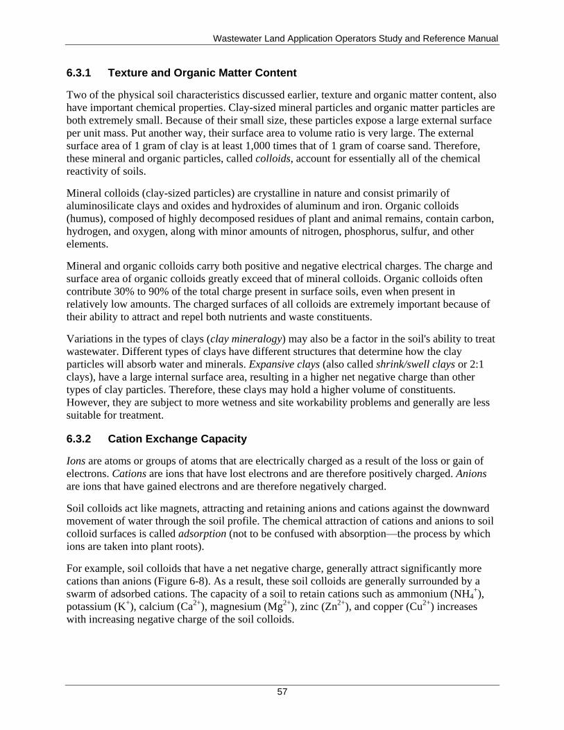
Wastewater Land Application Operators Study and Reference Manual
57
6.3.1 Texture and Organic Matter Content
Two of the physical soil characteristics discussed earlier, texture and organic matter content, also
have important chemical properties. Clay-sized mineral particles and organic matter particles are
both extremely small. Because of their small size, these particles expose a large external surface
per unit mass. Put another way, their surface area to volume ratio is very large. The external
surface area of 1 gram of clay is at least 1,000 times that of 1 gram of coarse sand. Therefore,
these mineral and organic particles, called colloids, account for essentially all of the chemical
reactivity of soils.
Mineral colloids (clay-sized particles) are crystalline in nature and consist primarily of
aluminosilicate clays and oxides and hydroxides of aluminum and iron. Organic colloids
(humus), composed of highly decomposed residues of plant and animal remains, contain carbon,
hydrogen, and oxygen, along with minor amounts of nitrogen, phosphorus, sulfur, and other
elements.
Mineral and organic colloids carry both positive and negative electrical charges. The charge and
surface area of organic colloids greatly exceed that of mineral colloids. Organic colloids often
contribute 30% to 90% of the total charge present in surface soils, even when present in
relatively low amounts. The charged surfaces of all colloids are extremely important because of
their ability to attract and repel both nutrients and waste constituents.
Variations in the types of clays (clay mineralogy) may also be a factor in the soil's ability to treat
wastewater. Different types of clays have different structures that determine how the clay
particles will absorb water and minerals. Expansive clays (also called shrink/swell clays or 2:1
clays), have a large internal surface area, resulting in a higher net negative charge than other
types of clay particles. Therefore, these clays may hold a higher volume of constituents.
However, they are subject to more wetness and site workability problems and generally are less
suitable for treatment.
6.3.2 Cation Exchange Capacity
Ions are atoms or groups of atoms that are electrically charged as a result of the loss or gain of
electrons. Cations are ions that have lost electrons and are therefore positively charged. Anions
are ions that have gained electrons and are therefore negatively charged.
Soil colloids act like magnets, attracting and retaining anions and cations against the downward
movement of water through the soil profile. The chemical attraction of cations and anions to soil
colloid surfaces is called adsorption (not to be confused with absorption—the process by which
ions are taken into plant roots).
For example, soil colloids that have a net negative charge, generally attract significantly more
cations than anions (Figure 6-8). As a result, these soil colloids are generally surrounded by a
swarm of adsorbed cations. The capacity of a soil to retain cations such as ammonium (NH4+),
potassium (K+), calcium (Ca
2+), magnesium (Mg
2+), zinc (Zn
2+), and copper (Cu
2+) increases
with increasing negative charge of the soil colloids.
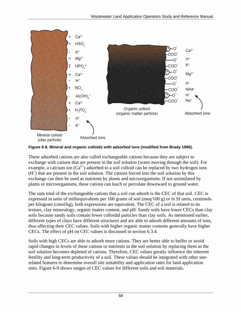
Wastewater Land Application Operators Study and Reference Manual
58
Figure 6-8. Mineral and organic colloids with adsorbed ions (modified from Brady 1990).
These adsorbed cations are also called exchangeable cations because they are subject to
exchange with cations that are present in the soil solution (water moving through the soil). For
example, a calcium ion (Ca2+
) adsorbed to a soil colloid can be replaced by two hydrogen ions
(H+) that are present in the soil solution. The cations forced into the soil solution by this
exchange can then be used as nutrients by plants and microorganisms. If not assimilated by
plants or microorganisms, these cations can leach or percolate downward to ground water.
The sum total of the exchangeable cations that a soil can adsorb is the CEC of that soil. CEC is
expressed in units of milliequivalents per 100 grams of soil (meq/100 g) or in SI units, centimols
per kilogram (cmol/kg), both expressions are equivalent. The CEC of a soil is related to its
texture, clay mineralogy, organic matter content, and pH. Sandy soils have lower CECs than clay
soils because sandy soils contain fewer colloidal particles than clay soils. As mentioned earlier,
different types of clays have different structures and are able to adsorb different amounts of ions,
thus affecting their CEC values. Soils with higher organic matter contents generally have higher
CECs. The effect of pH on CEC values is discussed in section 6.3.4.
Soils with high CECs are able to adsorb more cations. They are better able to buffer or avoid
rapid changes in levels of these cations or nutrients in the soil solution by replacing them as the
soil solution becomes depleted of cations. Therefore, CEC values greatly influence the inherent
fertility and long-term productivity of a soil. These values should be integrated with other site-
related features to determine overall site suitability and application rates for land application
sites. Figure 6-9 shows ranges of CEC values for different soils and soil materials.
Wastewater Land Application Operators Study and Reference Manual
59
Figure 6-9. Ranges in cation exchange capacities (at pH 7) that are typical of a variety of soils and soil materials. The high CEC of humus shows why this colloid plays such a prominent role in most soils (diagram courtesy of R. Weil) (Brady and Weil 2008).

Wastewater Land Application Operators Study and Reference Manual
60
6.3.3 Sodium Adsorption Ratio
SAR serves as an index of the potential sodium influence in the soil. SAR values above 13
classify soils as sodic or alkali, have sodium as the dominant cation, and may possibly
experience infiltration problems due to deflocculation (breakdown of peds) of soil colloids and
decreases soil infiltration. Certain textures of soils can become affected at values lower than 13.
6.3.4 pH
As discussed in section 5.3.7, pH is the measure of the concentration of the hydrogen ions in a
solution, and it indicates whether a soil is acidic (pH less than 7), alkaline (pH greater than 7, or
neutral (pH equal to 7). pH is a critical soil property because it influences many of the chemical
and biological reactions that take place in the soil. Figure 6-10 shows the range of various soil
types compared to familiar substances. Idaho soils cover a wide range of soils. Northern Idaho
soils and some central and northeastern Idaho soils can be represented with forest soils or humid
regions arable soils shown in Figure 6-10. Southern Idaho, on the other hand, can be represented
mainly by calcareous soils. Soil pH is not a constant, and for proper crop health, it may be
necessary in northern Idaho to raise the pH and in southern Idaho to lower the pH. This may be
done by using soil amendments such as lime (calcium carbonate) for raising pH and elemental
sulfur for lowering pH. Additional discussion on pH is given in the agronomy section of this
manual (section 6.7), which better discusses soil amendments, when to apply them, and typical
application rates.
Figure 6-10. Some pH values for familiar substances (above) compared to ranges of pH typical for various types of soils (below) (Brady and Weil 2008).
The CEC of a soil is directly influenced by its pH. Mineral soils with a pH near 6 are generally
the most efficient providers of plant nutrients, and crop health and yield are affected by pH.
When the pH is below 6.0, the charge on a mineral colloid is relatively constant. However, a
Wastewater Land Application Operators Study and Reference Manual
61
portion of the charge is pH dependent and increases when the pH is 6.0 or higher. The charge on
organic colloids is almost completely pH dependent. Therefore, the CEC of most soils increases
with an increase in pH.
Soil pH also influences the solubility of heavy metals and other nutrient cations and affects the
ability of plants to uptake these metals and nutrients. Soils that are very acid (pH of less than 5.5)
are more likely to release metals; plant uptake of these metals is prevented, and the potential for
metals to move into the ground water is increased. Soil pH is also important for maximizing crop
use of other available nutrients.
The bacteria that perform treatment in the soil are also strongly affected by soil pH. These
bacteria prefer a pH of neutral (or 7) for best performance. Any rapid increase or decrease in pH
can cause mortality in the bacteria population, resulting in poor water treatment.
Soil pH must be determined by laboratory analysis, although tools used to estimate pH in the
field can be useful for general guidance.
6.4 Soil Moisture
Both the physical and chemical properties of a soil can change as moisture conditions change. To
properly operate and maintain a land application system, an understanding of soil-water
relationships is essential. Become familiar with the following soil moisture terms:
Plant-available water (PAW)
Infiltration
Permeability
6.4.1 Plant-Available Water Content
Remember that a soil consists of soil particles and pore space. Pore space is filled with water, air
(actually gases such as oxygen, carbon dioxide, and nitrogen), or both.
When all of the pore space is filled with gases, the soil is said to be oven dry. An oven dry soil is
defined as a soil that has been dried at 105 °C until it reaches constant weight. An oven dry soil
contains no water.
At the other extreme is saturation; a saturated soil has all of its pore space filled with water. At
this point, the soil has reached its maximum retentive capacity (Figure 6-11).
Following rain or irrigation, a portion of the water held in the pores will drain from the soil due
to gravity (gravitational water). After 1 to 2 days, the gravitational drainage will become
negligible. At this time, the soil is said to be at field capacity. All of the water has been drained
from the macropores and has been replaced by gases. The remaining water is found in the
micropores. The micropores are small enough that the adhesive and cohesive forces holding the
water to the pore wall are stronger than the gravitational force trying to drain the soil. Water held
in the micropores at this point is available for use by plants.
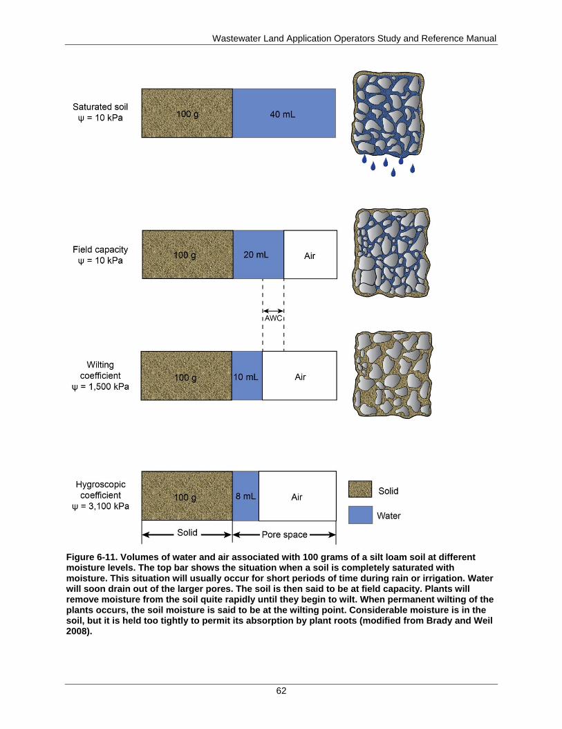
Wastewater Land Application Operators Study and Reference Manual
62
Figure 6-11. Volumes of water and air associated with 100 grams of a silt loam soil at different moisture levels. The top bar shows the situation when a soil is completely saturated with moisture. This situation will usually occur for short periods of time during rain or irrigation. Water will soon drain out of the larger pores. The soil is then said to be at field capacity. Plants will remove moisture from the soil quite rapidly until they begin to wilt. When permanent wilting of the plants occurs, the soil moisture is said to be at the wilting point. Considerable moisture is in the soil, but it is held too tightly to permit its absorption by plant roots (modified from Brady and Weil 2008).
Wastewater Land Application Operators Study and Reference Manual
63
As plants absorb water from the soil, they lose most of it through evaporation at leaf surfaces.
Simultaneously water is evaporated from the soil. As the soil dries, the amount of water available
to plants decreases. The initial response of plants is wilting. At the first onset of wilting, most
plants recover during times of reduced evaporation (i.e., at night). As the soil continues to dry,
the plants reach a point at which they cannot recover during periods of reduced evaporation. The
plants are now in a permanently wilted condition and will die if water is not provided. This point
is termed the permanent wilting point. The soil is not completely dry at this point, but the
remaining water is held so closely by soil particles that it is not available for use by plants.
PAW content is the maximum amount of water a soil can make available to plants. It is defined
as the difference between the water content at field capacity and the water content at the
permanent wilting point. PAW is equal to the available water-holding capacity (AWC) of the
soil, at a given root zone depth, expressed in inches of water per inch of soil, multiplied by the
actual root zone depth, expressed in inches. Estimated AWC values can be found in the Natural
Resources Conservation Service (NRCS) soils interpretation sheets or county soil surveys. PAW
is different from AWC in that it is only the water content that exists in the root zone at a given
time during plant growth, whereas, AWC is the total water content in the soil profile.
6.4.2 Infiltration
Infiltration is the movement of water into the soil. Infiltration rate is the maximum rate at which
water enters the soil and is expressed in inches per hour. Infiltration rate is a function of the
following:
Soil texture
Soil structure
Soil moisture
Vegetative cover
Topography and landscape position
The effects of texture and structure on water movement have already been discussed. The more
moisture a soil contains, the lower its infiltration rate. Infiltration rates decrease with the duration
of rain or irrigation and increasing soil moisture. When the soil is completely saturated, the
infiltration rate will be quite low.
A vegetative cover protects soil structure and increases infiltration rates. Without a cover, water
falling on or flowing over the soil destroys the soil’s structure, resulting in an impervious surface
crust. Level or gently sloping soils will have a higher infiltration rate than steeply sloping soils,
which promote runoff.
Therefore, a dry sandy soil on a level slope with a good vegetative cover would be expected to
have a high infiltration capacity, whereas a wet finely textured surface soil on a sparsely covered
steep slope would be expected to have a low infiltration capacity and to promote runoff.
6.4.3 Permeability
Permeability refers to the movement of water through soil. Permeability is expressed in inches
per hour. Soil texture and structure are the factors that most strongly influence permeability.
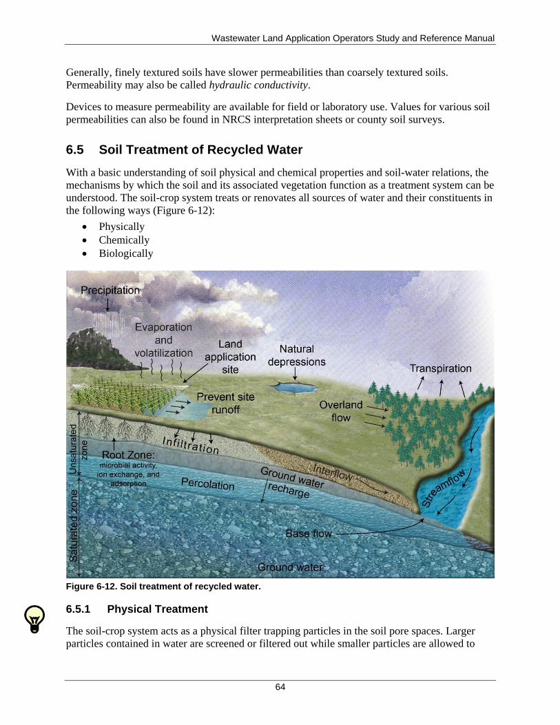
Wastewater Land Application Operators Study and Reference Manual
64
Generally, finely textured soils have slower permeabilities than coarsely textured soils.
Permeability may also be called hydraulic conductivity.
Devices to measure permeability are available for field or laboratory use. Values for various soil
permeabilities can also be found in NRCS interpretation sheets or county soil surveys.
6.5 Soil Treatment of Recycled Water
With a basic understanding of soil physical and chemical properties and soil-water relations, the
mechanisms by which the soil and its associated vegetation function as a treatment system can be
understood. The soil-crop system treats or renovates all sources of water and their constituents in
the following ways (Figure 6-12):
Physically
Chemically
Biologically
Figure 6-12. Soil treatment of recycled water.
6.5.1 Physical Treatment
The soil-crop system acts as a physical filter trapping particles in the soil pore spaces. Larger
particles contained in water are screened or filtered out while smaller particles are allowed to
Wastewater Land Application Operators Study and Reference Manual
65
pass through. As the soil collects more particles, the ability to screen smaller particles improves
because the space between soil particles decreases. Any solid materials remaining after
pretreatment are filtered from the recycled water during this process. These materials remain
close to the soil surface where other treatment processes can occur.
Appropriate soil texture and structure are essential for optimum physical treatment. Obviously, a
coarsely textured soil does not provide as good a filter as a finely textured soil because the pores
are too large to trap constituents. On the other hand, a finely textured soil needs sufficient
structural development to allow water to move downward through the profile at a moderate rate
and to allow clayey subsoil layers the opportunity to trap or bind the constituents in the water.
6.5.2 Chemical Treatment
The soil-crop system also acts as a chemical filter. The following chemical processes can alter
nutrients and constituents, such as inorganic chemicals, persistent organic compounds, and
pathogens:
Ion exchange—The transfer of ions between the soil solution and soil colloids. This
exchange allows ions to move back and forth between the soil solution and soil colloids,
becoming available for uptake by plants and microorganisms as needed.
Adsorption—The bonding of ions to the surface of soil colloids by weak chemical
reactions. Ions are held by the soil until taken up by plants or microorganisms. Viruses
can also be adsorbed onto soil particles.
Precipitation—A reaction in which an insoluble solid is formed from two or more soluble
ions or compounds. For example, alum is often added to wastewater to remove phosphate
by precipitation.
Chelation—A process by which metallic ions are firmly bound by organic molecules;
also called complexation. Organic molecules retain heavy metals as if held by a claw (the
word chelate comes from the Greek word for claw). Although plants normally do take up
the organic chelating agents, these agents apparently hold the metallic ions near plant
roots until absorption of the ions can take place. While they are bound or complexed with
the organic chelating agents, metallic ions are prevented from interacting with other
compounds in the soil that could make them unavailable to plants.
Volatilization—The chemical transformation of a substance into a gas that can evaporate
or escape to the atmosphere. For example, under certain conditions, the ammonium form
of nitrogen (NH4+) volatilizes to ammonia gas (NH3), which can be released to the
atmosphere.
A soil's ability to treat chemically depends on soil texture and structure, pH, soil temperature,
organic matter content, and presence of clay or hydrous oxides. Finely textured soils with a pH
greater than 6.5 provide the most effective chemical treatment.
6.5.3 Biological Treatment
The soil-plant system contains numerous living organisms, such as fungi and bacteria, that
decompose or alter material placed on or in the soil. It is estimated that there may be as many as
8,000 pounds of microorganisms per acre in the first 6 inches of soil. Microorganisms alter or
destroy water constituents through the following biological processes:
Wastewater Land Application Operators Study and Reference Manual
66
Mineralization—The conversion of an element from an organic form to an inorganic
form by microbial decomposition. For example, microorganisms attack organic nitrogen
in the soil (present as proteins or amino acids). These microorganisms break down the
complex organic compounds, releasing nitrogen in its inorganic forms (NH4+ and NO3
-),
also known as nitrification. It is the inorganic forms of most nutrients that are available
for uptake by plants and microorganisms.
Immobilization—The reverse of mineralization. Immobilization is the incorporation of an
inorganic element into an organic form (plant or microbial tissue). Using nitrogen as an
example again, inorganic forms of nitrogen (NH4+
or NO3-) are consumed by
microorganisms and converted into organic tissue. The nitrogen is now bound up in the
bodies of the microorganisms and is no longer readily available to other microorganisms
or plants.
Consumption—The use of organic matter present in waste as an energy source by
microorganisms. Microorganisms feed and grow on constituents, resulting in the
decomposition of these constituents. As the organisms grow and reproduce, more and
more constituents are removed.
Elimination—The process by which microorganisms destroy or alter pathogens or
chemical compounds.
Denitrification—The biological transformation of the nitrate and nitrite forms of nitrogen
to gaseous nitrogen, which can escape to the atmosphere.
The soils ability to biologically treat depends on soil temperature, microorganism populations,
chemical ratios (such as the C:N ratio), and the amount of organic matter present in the soil.
6.6 Fate of Water Constituents
Different water constituents are subject to different fates once they enter the soil-crop system.
Nitrogen can be
Mineralized
Taken up by crops
Immobilized
Adsorbed onto soil colloids
Lost as a gas to the atmosphere through volatilization or denitrification
Leached to ground water, if not properly managed
Phosphorus can be
Mineralized
Taken up by crops
Immobilized
Adsorbed onto soil colloids
Precipitated
Leached to ground water, if not properly managed
Wastewater Land Application Operators Study and Reference Manual
67
Metals can be
Mineralized
Taken up by crops
Complexed by chelates
Adsorbed onto soil colloids
Precipitated
Leached to ground water, if not properly managed
Pathogens can be
Consumed or eliminated by soil microorganisms
Adsorbed onto soil colloids
Complexed by chelates
Killed by unfavorable environmental conditions
Destroyed by exposure to ultraviolet light
Leached to ground water, if not properly managed
Persistent organic chemicals can be
Consumed or eliminated by soil microorganisms
Absorbed by plants
Chemically decomposed
Adsorbed onto soil colloids
Volatilized
Broken down by ultraviolet light
Leached to ground water
6.7 Agronomy
Plants are an integral part of the natural treatment system. It is important, therefore, that WWLA
operators have a basic understanding of agronomy. Agronomy is the study of the various
physical and biological factors related to crop production. While crop production is not the
primary concern of a land application system, a healthy vegetative cover is essential for the
natural treatment system to function properly. Important functions that plants perform include
the following:
Nutrient uptake
Water consumption
Enhance evapotranspiration
Stabilize soil and prevent erosion
Provide food and habitat for soil organisms that break down and use water constituents
6.7.1 Essential Nutrients
Although many factors affect the growth of plants, the WWLA operator has a great deal of
control over the supply of essential nutrients. Plants require at least 16 elements for normal
growth and for completion of their life cycle. Carbon, hydrogen, and oxygen are the elements
used in the largest amounts; these nonmineral elements are supplied by air and water. Plants
Wastewater Land Application Operators Study and Reference Manual
68
must obtain the other 13 elements from the soil or from amendments added to the soil (fertilizers
or recycled water).
6.7.1.1 Macronutrients
Plants need relatively large amounts of nitrogen, phosphorus, and potassium. These nutrients are
the ones most frequently supplied to plants by fertilizers. Calcium, magnesium, and sulfur are
required in somewhat smaller amounts. These six elements, along with carbon, hydrogen, and
oxygen, are considered macronutrients.
6.7.1.2 Micronutrients
In contrast to these macronutrients, the micronutrients consist of eight essential elements: boron,
copper, chlorine, iron, manganese, molybdenum, nickel, and zinc. These elements occur in very
small amounts in both soils and plants, but their role is equally as important as the
macronutrients. A deficiency of one or more of the micronutrients can result in severe reductions
in growth, yield, and crop quality.
Some soils do not contain sufficient amounts of these nutrients to meet the plant's requirements
for rapid growth and good production. In such cases, supplemental micronutrient applications in
the form of commercial fertilizers or foliar sprays must be made. Table 6-2 lists the 16 essential
macronutrients and micronutrients required for plant growth.
6.7.1.3 Heavy Metals
While the use of the term micronutrient has been common in agricultural circles for some time,
the use of the term heavy metal is becoming more common because of environmental concerns.
Heavy metals are a group of elements that are associated with industrial and municipal
wastewater residuals. At certain levels or concentrations, these elements pose toxicity problems
to plants and animals. Included in this group are eight metals: cadmium, chromium, copper, lead,
mercury, molybdenum, nickel, and zinc.
In addition to these metals, two nonmetals, arsenic and selenium, are also included in EPA’s
pollutant concentration list. These two elements are often inaccurately included or referred to as
heavy metals.
Heavy metals contain three micronutrients: copper, molybdenum, and zinc, all of which are
required for plant growth. It may seem like a contradiction for an element to be an essential
nutrient on the one hand, and a toxic or a pollutant on the other, but although low concentrations
of these elements are required for growth, at higher levels they can become toxic. It is important
for WWLA operators to understand this difference to prevent too much of a good thing from
becoming a problem.
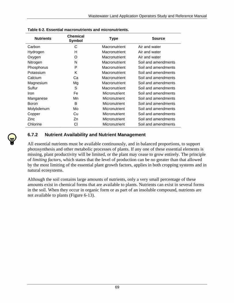
Wastewater Land Application Operators Study and Reference Manual
69
Table 6-2. Essential macronutrients and micronutrients.
Nutrients Chemical Symbol
Type Source
Carbon
Hydrogen
Oxygen
Nitrogen
Phosphorus
Potassium
Calcium
Magnesium
Sulfur
Iron
Manganese
Boron
Molybdenum
Copper
Zinc
Chlorine
C
H
O
N
P
K
Ca
Mg
S
Fe
Mn
B
Mo
Cu
Zn
Cl
Macronutrient
Macronutrient
Macronutrient
Macronutrient
Macronutrient
Macronutrient
Macronutrient
Macronutrient
Macronutrient
Micronutrient
Micronutrient
Micronutrient
Micronutrient
Micronutrient
Micronutrient
Micronutrient
Air and water
Air and water
Air and water
Soil and amendments
Soil and amendments
Soil and amendments
Soil and amendments
Soil and amendments
Soil and amendments
Soil and amendments
Soil and amendments
Soil and amendments
Soil and amendments
Soil and amendments
Soil and amendments
Soil and amendments
6.7.2 Nutrient Availability and Nutrient Management
All essential nutrients must be available continuously, and in balanced proportions, to support
photosynthesis and other metabolic processes of plants. If any one of these essential elements is
missing, plant productivity will be limited, or the plant may cease to grow entirely. The principle
of limiting factors, which states that the level of production can be no greater than that allowed
by the most limiting of the essential plant growth factors, applies in both cropping systems and in
natural ecosystems.
Although the soil contains large amounts of nutrients, only a very small percentage of these
amounts exist in chemical forms that are available to plants. Nutrients can exist in several forms
in the soil. When they occur in organic form or as part of an insoluble compound, nutrients are
not available to plants (Figure 6-13).
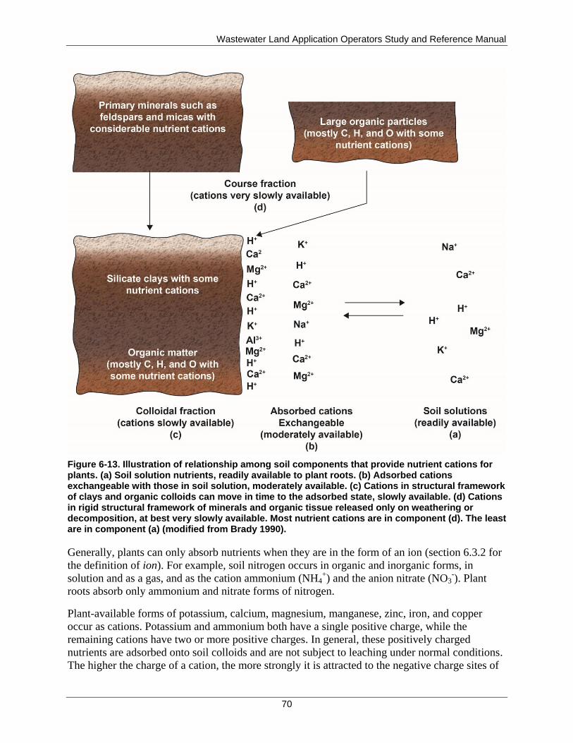
Wastewater Land Application Operators Study and Reference Manual
70
Figure 6-13. Illustration of relationship among soil components that provide nutrient cations for plants. (a) Soil solution nutrients, readily available to plant roots. (b) Adsorbed cations exchangeable with those in soil solution, moderately available. (c) Cations in structural framework of clays and organic colloids can move in time to the adsorbed state, slowly available. (d) Cations in rigid structural framework of minerals and organic tissue released only on weathering or decomposition, at best very slowly available. Most nutrient cations are in component (d). The least are in component (a) (modified from Brady 1990).
Generally, plants can only absorb nutrients when they are in the form of an ion (section 6.3.2 for
the definition of ion). For example, soil nitrogen occurs in organic and inorganic forms, in
solution and as a gas, and as the cation ammonium (NH4+) and the anion nitrate (NO3
-). Plant
roots absorb only ammonium and nitrate forms of nitrogen.
Plant-available forms of potassium, calcium, magnesium, manganese, zinc, iron, and copper
occur as cations. Potassium and ammonium both have a single positive charge, while the
remaining cations have two or more positive charges. In general, these positively charged
nutrients are adsorbed onto soil colloids and are not subject to leaching under normal conditions.
The higher the charge of a cation, the more strongly it is attracted to the negative charge sites of
Wastewater Land Application Operators Study and Reference Manual
71
the soil. However, when the sum of the positively charged nutrients exceeds the soil's capacity to
hold nutrients, these nutrients may be lost through leaching.
One form of plant-available nitrogen is nitrate (NO3-). The plant-available form of chlorine is the
anion chloride (Cl-). Both of these anions are repelled by the negative charges of soil colloids.
Therefore, they are readily leached when water passes through the soil. The plant-available
forms of sulfur (sulfate [SO42-
]) and molybdenum (molybdate [MoO42-
]) have two negative
charges and are also repelled by negatively charged soil colloids. However, these anions may
react weakly with positively charged sites, such as occur on iron oxides. Although these elements
are not strongly bound to soil colloids under normal conditions, they do not leach as readily as
nitrate and chloride and are frequently observed to increase in subsoil horizons having higher
clay content and lower pH.
Plant-available phosphorus occurs as an anion with either one or two negative charges,
depending on soil pH. Although other anions normally leach readily, phosphorus does not.
Phosphorus reacts very strongly with iron, aluminum, and calcium in soil solution, with soil
solids such as iron oxides, iron and aluminum hydroxides, and with lime. The strength of these
reactions limits the movement of phosphorus.
Boron occurs as a leachable, uncharged molecule (boric acid, H3BO3), which reacts very weakly
with soil clays.
The availability of nutrients is influenced by the following factors:
pH
Soil texture
The form of nutrient present in the water
The amount of nutrient present in the soil and soil-water solution
6.7.2.1 pH
Crop nutrient availability is strongly tied to the pH of the soil solution. Decreasing soil pH
directly increases the solubility of manganese, zinc, copper, and iron, thereby increasing the
availability of these nutrients. At pH values less than 5.5, toxic levels of manganese, zinc, or
aluminum (a non-nutrient element common in soils) may be released. On the other hand, the
availability of nitrogen, potassium, calcium, magnesium, and sulfur tends to decrease with
decreasing pH.
Phosphorus and boron availability decreases at both very low and very high pH, with maximum
availability in the range of pH 5.5 to 7.0. Outside of this pH range, phosphorus and boron tend to
form insoluble compounds with other elements, such as aluminum, iron, manganese, and
calcium. These reactions bind phosphorus much more strongly than boron, with the result that
available boron can be readily leached from soils.
Soil pH can sometimes be altered with amendments. As mentioned previously, two widely used
soil amendments are lime used to raise the pH and elemental sulfur used to lower the pH.
Increasing soil pH, however, is sometimes not the primary reason for liming. As discussed,
aluminum and manganese are toxic to plants at relatively low concentrations in the soil solution.
Wastewater Land Application Operators Study and Reference Manual
72
Low pH may be an indicator that aluminum and manganese toxicity is taking place. Liming
decreases the solubility of aluminum, manganese, and iron (as well as zinc and copper), causing
them to precipitate as relatively insoluble silicate clays, oxides, and hydroxides. Gypsum is
another soil amendment that can be used to reduce aluminum toxicity without raising the pH.
Figure 6-14 shows the relationship between pH and nutrient availability. Typically if adequate
phosphorus is provided to the crop system (pH between 5.5 and 7) all other essential nutrients
will adequately be provided as seen in Figure 6-14.
If soil pH needs to be raised or lowered, the timing and application rate of soil amendments are
critical for healthy crops and a bountiful harvest. The soil class, soil starting pH, soil buffering
ability, soil temperature, and soil moisture content have an effect on how much soil amendment
is needed and how fast or to what degree the pH will change. Elemental sulfur is especially
dependent on temperature and moisture content. Typically sulfur should be applied in spring
with soil temperatures above 75ºF and 4–6 weeks should be allowed before the desired pH
change is realized. Sulfur should also be well mixed with the soil so that the soil microorganisms
can oxidize the sulfur and produce sulfuric acid to acidify the soil. As an example, it is
recommended that for each unit drop in pH desired, a well buffered soil (e.g., a silty clay loam
with 4% organic matter) will require about 0.5 tons/acre of elemental sulfur (Brady and Weil
2008). Lime can be used as a soil amendment to raise soil pH in acidic soils. These soils are
typically not found in southern Idaho but may be found in northern Idaho. The University of
Idaho fertilizer guide for alfalfa grown in northern Idaho makes the following recommendation
for liming in acidic soils: “If soil pH is between 5.5 and 5.8 apply 1 ton of lime per acre and
thoroughly incorporate into the soil prior to seeding alfalfa. If the soil pH is less than 5.4, apply
2 tons of lime per acre and incorporate it into the soil prior to seeding alfalfa.” For additional
information on lime and liming materials, see University of Idaho CIS 787, Liming Materials
(Mahler 2005).
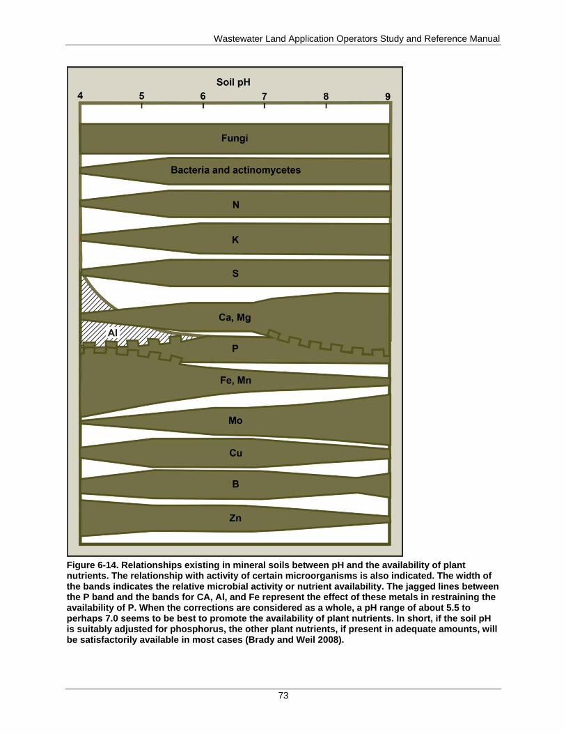
Wastewater Land Application Operators Study and Reference Manual
73
Figure 6-14. Relationships existing in mineral soils between pH and the availability of plant nutrients. The relationship with activity of certain microorganisms is also indicated. The width of the bands indicates the relative microbial activity or nutrient availability. The jagged lines between the P band and the bands for CA, Al, and Fe represent the effect of these metals in restraining the availability of P. When the corrections are considered as a whole, a pH range of about 5.5 to perhaps 7.0 seems to be best to promote the availability of plant nutrients. In short, if the soil pH is suitably adjusted for phosphorus, the other plant nutrients, if present in adequate amounts, will be satisfactorily available in most cases (Brady and Weil 2008).
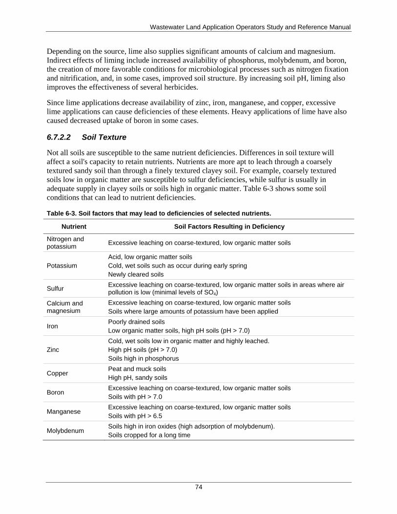
Wastewater Land Application Operators Study and Reference Manual
74
Depending on the source, lime also supplies significant amounts of calcium and magnesium.
Indirect effects of liming include increased availability of phosphorus, molybdenum, and boron,
the creation of more favorable conditions for microbiological processes such as nitrogen fixation
and nitrification, and, in some cases, improved soil structure. By increasing soil pH, liming also
improves the effectiveness of several herbicides.
Since lime applications decrease availability of zinc, iron, manganese, and copper, excessive
lime applications can cause deficiencies of these elements. Heavy applications of lime have also
caused decreased uptake of boron in some cases.
6.7.2.2 Soil Texture
Not all soils are susceptible to the same nutrient deficiencies. Differences in soil texture will
affect a soil's capacity to retain nutrients. Nutrients are more apt to leach through a coarsely
textured sandy soil than through a finely textured clayey soil. For example, coarsely textured
soils low in organic matter are susceptible to sulfur deficiencies, while sulfur is usually in
adequate supply in clayey soils or soils high in organic matter. Table 6-3 shows some soil
conditions that can lead to nutrient deficiencies.
Table 6-3. Soil factors that may lead to deficiencies of selected nutrients.
Nutrient Soil Factors Resulting in Deficiency
Nitrogen and potassium
Excessive leaching on coarse-textured, low organic matter soils
Potassium
Acid, low organic matter soils
Cold, wet soils such as occur during early spring
Newly cleared soils
Sulfur Excessive leaching on coarse-textured, low organic matter soils in areas where air pollution is low (minimal levels of SO4)
Calcium and magnesium
Excessive leaching on coarse-textured, low organic matter soils
Soils where large amounts of potassium have been applied
Iron Poorly drained soils
Low organic matter soils, high pH soils (pH > 7.0)
Zinc
Cold, wet soils low in organic matter and highly leached.
High pH soils (pH > 7.0)
Soils high in phosphorus
Copper Peat and muck soils
High pH, sandy soils
Boron Excessive leaching on coarse-textured, low organic matter soils
Soils with pH > 7.0
Manganese Excessive leaching on coarse-textured, low organic matter soils
Soils with pH > 6.5
Molybdenum Soils high in iron oxides (high adsorption of molybdenum).
Soils cropped for a long time
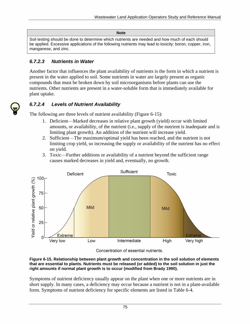
Wastewater Land Application Operators Study and Reference Manual
75
Note
Soil testing should be done to determine which nutrients are needed and how much of each should be applied. Excessive applications of the following nutrients may lead to toxicity: boron, copper, iron, manganese, and zinc.
6.7.2.3 Nutrients in Water
Another factor that influences the plant availability of nutrients is the form in which a nutrient is
present in the water applied to soil. Some nutrients in water are largely present as organic
compounds that must be broken down by soil microorganisms before plants can use the
nutrients. Other nutrients are present in a water-soluble form that is immediately available for
plant uptake.
6.7.2.4 Levels of Nutrient Availability
The following are three levels of nutrient availability (Figure 6-15):
1. Deficient—Marked decreases in relative plant growth (yield) occur with limited
amounts, or availability, of the nutrient (i.e., supply of the nutrient is inadequate and is
limiting plant growth). An addition of the nutrient will increase yield.
2. Sufficient—The maximum/optimal yield has been reached, and the nutrient is not
limiting crop yield, so increasing the supply or availability of the nutrient has no effect
on yield.
3. Toxic—Further additions or availability of a nutrient beyond the sufficient range
causes marked decreases in yield and, eventually, no growth.
Figure 6-15. Relationship between plant growth and concentration in the soil solution of elements that are essential to plants. Nutrients must be released (or added) to the soil solution in just the right amounts if normal plant growth is to occur (modified from Brady 1990).
Symptoms of nutrient deficiency usually appear on the plant when one or more nutrients are in
short supply. In many cases, a deficiency may occur because a nutrient is not in a plant-available
form. Symptoms of nutrient deficiency for specific elements are listed in Table 6-4.
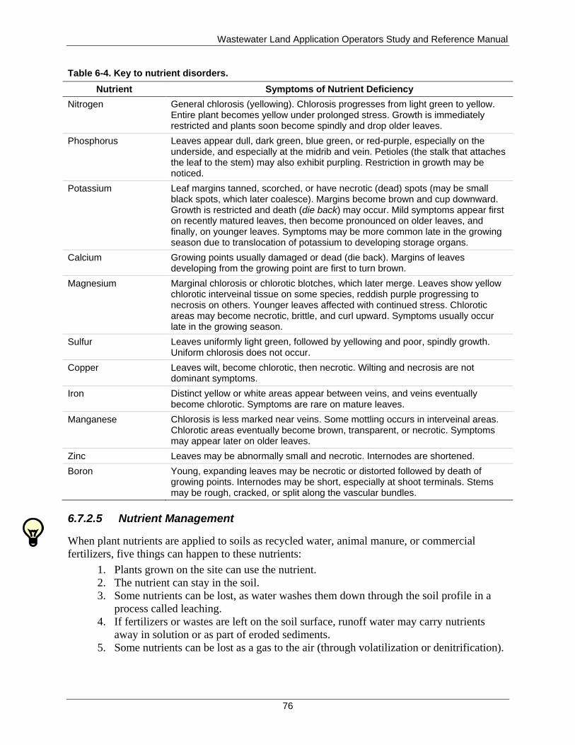
Wastewater Land Application Operators Study and Reference Manual
76
Table 6-4. Key to nutrient disorders.
Nutrient Symptoms of Nutrient Deficiency
Nitrogen General chlorosis (yellowing). Chlorosis progresses from light green to yellow. Entire plant becomes yellow under prolonged stress. Growth is immediately restricted and plants soon become spindly and drop older leaves.
Phosphorus Leaves appear dull, dark green, blue green, or red-purple, especially on the underside, and especially at the midrib and vein. Petioles (the stalk that attaches the leaf to the stem) may also exhibit purpling. Restriction in growth may be noticed.
Potassium Leaf margins tanned, scorched, or have necrotic (dead) spots (may be small black spots, which later coalesce). Margins become brown and cup downward. Growth is restricted and death (die back) may occur. Mild symptoms appear first on recently matured leaves, then become pronounced on older leaves, and finally, on younger leaves. Symptoms may be more common late in the growing season due to translocation of potassium to developing storage organs.
Calcium Growing points usually damaged or dead (die back). Margins of leaves developing from the growing point are first to turn brown.
Magnesium Marginal chlorosis or chlorotic blotches, which later merge. Leaves show yellow chlorotic interveinal tissue on some species, reddish purple progressing to necrosis on others. Younger leaves affected with continued stress. Chlorotic areas may become necrotic, brittle, and curl upward. Symptoms usually occur late in the growing season.
Sulfur Leaves uniformly light green, followed by yellowing and poor, spindly growth. Uniform chlorosis does not occur.
Copper Leaves wilt, become chlorotic, then necrotic. Wilting and necrosis are not dominant symptoms.
Iron Distinct yellow or white areas appear between veins, and veins eventually become chlorotic. Symptoms are rare on mature leaves.
Manganese Chlorosis is less marked near veins. Some mottling occurs in interveinal areas. Chlorotic areas eventually become brown, transparent, or necrotic. Symptoms may appear later on older leaves.
Zinc Leaves may be abnormally small and necrotic. Internodes are shortened.
Boron Young, expanding leaves may be necrotic or distorted followed by death of growing points. Internodes may be short, especially at shoot terminals. Stems may be rough, cracked, or split along the vascular bundles.
6.7.2.5 Nutrient Management
When plant nutrients are applied to soils as recycled water, animal manure, or commercial
fertilizers, five things can happen to these nutrients:
1. Plants grown on the site can use the nutrient.
2. The nutrient can stay in the soil.
3. Some nutrients can be lost, as water washes them down through the soil profile in a
process called leaching.
4. If fertilizers or wastes are left on the soil surface, runoff water may carry nutrients
away in solution or as part of eroded sediments.
5. Some nutrients can be lost as a gas to the air (through volatilization or denitrification).

Wastewater Land Application Operators Study and Reference Manual
77
To maximize nutrient use, the WWLA operator should develop a nutrient management plan.
Developing such a plan requires information on the amount of nutrients that can be applied to
meet the agronomic need of the crop or vegetation grown, the form or source of nutrients, the
placement of nutrients on the field, and the timing of nutrient applications. Nutrients can be
managed by adjusting these four components.
The term agronomic rate means that nutrients will be applied in accordance with the needs of the
crop or vegetation. Thus, rates and timing of application must be adjusted to optimize plant
response to the applied nutrients. When this occurs, the plant’s ability to use the nutrients is
maximized, so fewer nutrients can escape into the environment. Efficient nutrient management is
a goal for all systems, whether they are growing trees or vegetables, or managing pasture at a
land application site.
6.8 Crop Nutrient Requirements
WWLA operators must understand nutrient requirements and growth cycles of the plants being
grown. Crops vary in their ability to use nutrients (crop uptake). Bermuda grass has very high
nutrient requirements, whereas a mature forest has much lower requirements.
DEQ defines typical crop uptake as the median constituent crop uptake from the 3 most recent
years the crop has been grown. For crops having less than 3 years of actual crop uptake data,
other crop yield data or nutrient content values may only be used if approved in writing by DEQ
in advance of use. If written approval is not provided by DEQ, compliance with the permit
nitrogen loading limit shall be determined by comparing the current year nitrogen loading to the
current year nitrogen uptake.
Domestic wastewater generally contains low concentrations of the major plant nutrients. In such
cases, it is possible that plant nutrients such as nitrogen, phosphorus, and potassium may have to
be added as supplemental fertilizers, manures, compost, or soil amendments to get expected crop
yields (optimum crop growth). Insufficient nutrients may result in reduced crop yield and
reduced nutrient uptake efficiencies. The addition of supplemental nutrients should be based on
soil test recommendations and expected crop yields. WWLA operators are encouraged to consult
DEQ, the local Cooperative Extension Service, NRCS, or agricultural consultants for assistance
in interpreting soil test results, determining potential supplemental fertilization rates, and
developing nutrient management plans. Any supplemental source of nutrients will have to be
documented and reported as part of the reuse permit requirements.

Wastewater Land Application Operators Study and Reference Manual
78
This page intentionally left blank for correct double-sided printing.

Wastewater Land Application Operators Study and Reference Manual
79
7 Ground Water and Hydrology
Need-to-Know Criteria
Hydrologic cycle and land application
Evapotranspiration
Runoff to surface waters, surface water pollution, and ponding
Soil water and water table depths
Monitoring wells and well construction
To determine if a land application treatment system is functioning properly, the WWLA operator
needs a basic understanding of ground water and hydrology. Hydrology is simply the study of
water as it occurs on and below the surface of the earth as well as in the atmosphere. The
movement of water on the land, in the ground, and through the air is termed the hydrologic cycle.
7.1 Hydrologic Cycle
The hydrologic cycle is the continuous process of water leaving the earth's surface and
eventually returning in the form of precipitation (Figure 7-1). Water falling from the atmosphere
as rain or snow can do one of three things:
1. Evaporate and return to the atmosphere.
2. Run off to streams, rivers, lakes, and oceans.
3. Infiltrate into the soil.
Land-applied recycled water acts in much the same way as natural precipitation and becomes a
part of the hydrologic cycle. In a properly operated land application system, however, recycled
water should either evaporate or infiltrate into the soil.
Runoff from land application is not acceptable. Percolation of untreated or partially treated
recycled water below the root zone is also undesirable. Therefore, one of the most important
goals for the WWLA operator is to apply recycled water at rates that will not only supply the
nutrient needs of crops or vegetative covers but that will not exceed the rate at which the soil-
crop system will accept, hold, and use the water. WWLA operators should understand that if not
properly managed, recycled water can pond on the soil surface, percolate to deeper ground water,
or flow laterally as ground water until it reaches a surface water body (surface water and ground
water interconnection).
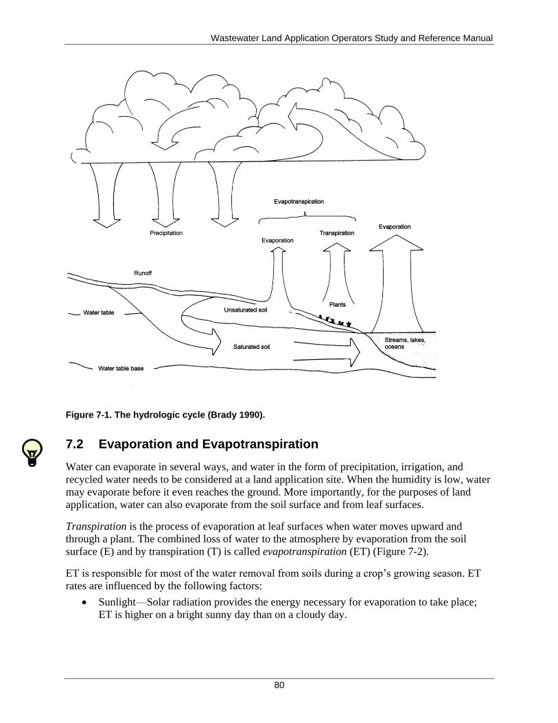
Wastewater Land Application Operators Study and Reference Manual
80
Figure 7-1. The hydrologic cycle (Brady 1990).
7.2 Evaporation and Evapotranspiration
Water can evaporate in several ways, and water in the form of precipitation, irrigation, and
recycled water needs to be considered at a land application site. When the humidity is low, water
may evaporate before it even reaches the ground. More importantly, for the purposes of land
application, water can also evaporate from the soil surface and from leaf surfaces.
Transpiration is the process of evaporation at leaf surfaces when water moves upward and
through a plant. The combined loss of water to the atmosphere by evaporation from the soil
surface (E) and by transpiration (T) is called evapotranspiration (ET) (Figure 7-2).
ET is responsible for most of the water removal from soils during a crop’s growing season. ET
rates are influenced by the following factors:
Sunlight—Solar radiation provides the energy necessary for evaporation to take place;
ET is higher on a bright sunny day than on a cloudy day.
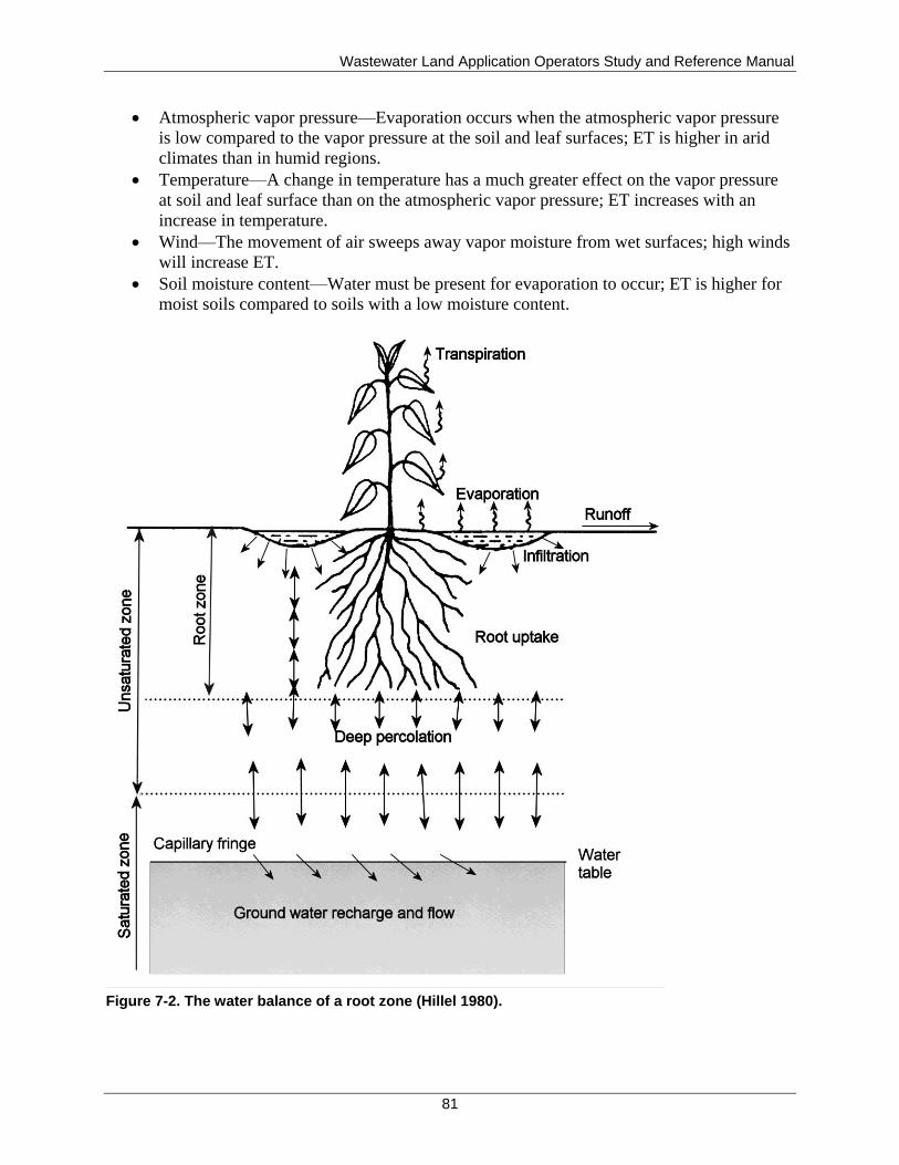
Wastewater Land Application Operators Study and Reference Manual
81
Atmospheric vapor pressure—Evaporation occurs when the atmospheric vapor pressure
is low compared to the vapor pressure at the soil and leaf surfaces; ET is higher in arid
climates than in humid regions.
Temperature—A change in temperature has a much greater effect on the vapor pressure
at soil and leaf surface than on the atmospheric vapor pressure; ET increases with an
increase in temperature.
Wind—The movement of air sweeps away vapor moisture from wet surfaces; high winds
will increase ET.
Soil moisture content—Water must be present for evaporation to occur; ET is higher for
moist soils compared to soils with a low moisture content.
Figure 7-2. The water balance of a root zone (Hillel 1980).
Wastewater Land Application Operators Study and Reference Manual
82
After ET occurs, water vapor in the atmosphere condenses into clouds. Eventually precipitation
falls in the form of rain or snow and the cycle begins again.
7.3 Runoff to Surface Waters
Water that does not evaporate to the atmosphere or infiltrate into the soil can accumulate and
pond in the field and if sufficient slope is present, the excess water may run off the field. Runoff
travels over the soil surface and may transport soil particles and nutrients from the field to nearby
surface water if present (i.e., streams, rivers, lakes, and oceans). Factors affecting runoff are the
same as those affecting infiltration (section 6.4.2):
Soil texture
Soil structure
Soil moisture
Vegetative cover
Topography and landscape position
Runoff can negatively impact both soil and water quality. These negative impacts include soil
erosion and surface water pollution. Nutrients contained in the runoff, especially phosphorus,
have the potential for causing surface water quality impacts.
7.3.1 Soil Erosion
When runoff occurs, it carries suspended soil particles. This loss or movement of soil is called
soil erosion. Around 5 billion metric tons of soil is moved annually in the United States, some
two-thirds is moved by water (the remainder is moved by wind).
Unfortunately, much of this eroded soil ends up in surface waters. Sediment carried by runoff
clogs streams, fills lakes, and often carries nutrients and pollutants to these waters. It can reduce
the capacity of water storage reservoirs, require dredging of rivers and streams, and can impact
both water and wastewater treatment plants by increased sediment loads.
Runoff high in sediment can cause turbidity, which can smother aquatic life and shade out
desirable aquatic vegetation. Sediment also may carry pesticides—such as herbicides and
insecticides—that may be toxic to aquatic plants and animals. The varying chemical properties of
pesticides—for example, their solubility, toxicity, and chemical breakdown rate—determine the
potential damage to water quality.
Reducing soil erosion is the key to reducing the damaging effects of sedimentation. Fortunately,
with current technology and management practices, erosion can be reduced to acceptable levels.
The challenge is to match the appropriate technology to each situation.
7.3.2 Surface Water Pollution
In addition to soil particles, runoff can carry with it other constituents that affect water quality.
Bacteria, viruses, organics, and a variety of other chemicals may impact plant and animal life in
surface waters. These pollutants also have the potential to impact humans who use these surface
waters for fishing, recreation, or drinking water.
Wastewater Land Application Operators Study and Reference Manual
83
Nutrients carried by runoff to surface waters can also result in accelerated eutrophication.
Natural eutrophication is the slow nutrient enrichment of streams and lakes and is responsible for
the aging of ponds, lakes, and reservoirs.
Rapid eutrophication is usually associated with increased algae growth or blooms. In freshwater
ecosystems developed under very low phosphorus conditions, large additions of nutrients,
especially phosphorus, can stimulate the production of these algae blooms. As the algae die,
organisms in the aquatic system decompose the algae to use as a food source. In the process, they
also use significant amounts of oxygen. As more and more algae grow and then decompose,
dissolved oxygen levels are depleted. This condition can result in fish kills, offensive odors,
unsightliness, and reduced attractiveness of the water for recreation and other public uses.
7.3.3 Ponding
If the topography of a land application site includes low-lying areas, runoff may collect in these
areas and create ponding. Ponding can also occur in the field at the original point of application.
Ponding can cause hydraulic overloading and result in ground water contamination by leaching
water past the crop root zone. In addition, land application sites should be managed to prevent
water from ponding to the point where the ponded water putrefies (decomposition of waste
elements in the water), which may cause odors or supports vectors (such as birds, flies
mosquitoes, or rats) that may transmit disease.
7.4 Infiltration into the Soil
As discussed in the following sections, factors important to soil infiltration include soil water,
water table depths, artificial affects to site hydrology, and ground water monitoring wells.
7.4.1 Soil Water
Water that does not evaporate or move as surface runoff, infiltrates into the soil, and percolates
downward. As discussed in section 7.2, some of this water is used by plants and is removed from
the soil environment by ET. The remaining water flows through the unsaturated portion of the
soil (unsaturated zone) and below the root zone until it reaches the saturated zone (Figure 7-3).
This is the zone in which all of the pores in the soil or bedrock are filled with water. The surface
or uppermost level of the saturated zone is called the water table. When water percolating
through the soil reaches the water table, it becomes ground water. Ground water is any water
contained in interconnected pores located below the water table.
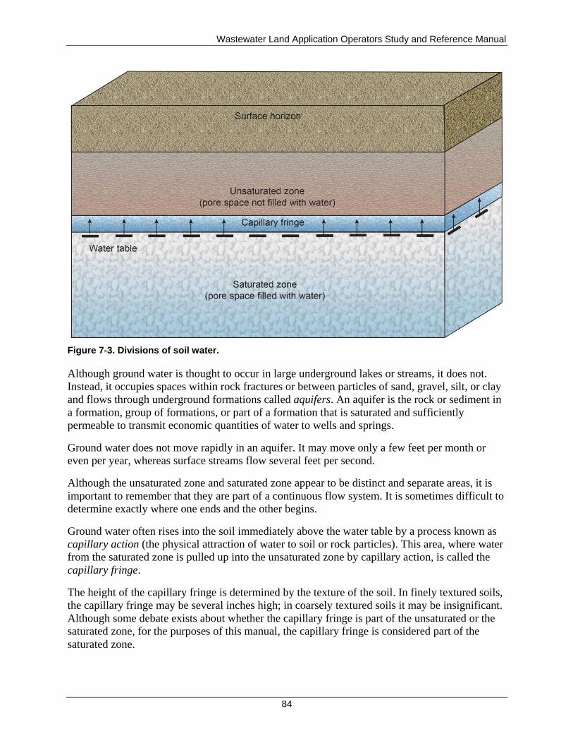
Wastewater Land Application Operators Study and Reference Manual
84
Figure 7-3. Divisions of soil water.
Although ground water is thought to occur in large underground lakes or streams, it does not.
Instead, it occupies spaces within rock fractures or between particles of sand, gravel, silt, or clay
and flows through underground formations called aquifers. An aquifer is the rock or sediment in
a formation, group of formations, or part of a formation that is saturated and sufficiently
permeable to transmit economic quantities of water to wells and springs.
Ground water does not move rapidly in an aquifer. It may move only a few feet per month or
even per year, whereas surface streams flow several feet per second.
Although the unsaturated zone and saturated zone appear to be distinct and separate areas, it is
important to remember that they are part of a continuous flow system. It is sometimes difficult to
determine exactly where one ends and the other begins.
Ground water often rises into the soil immediately above the water table by a process known as
capillary action (the physical attraction of water to soil or rock particles). This area, where water
from the saturated zone is pulled up into the unsaturated zone by capillary action, is called the
capillary fringe.
The height of the capillary fringe is determined by the texture of the soil. In finely textured soils,
the capillary fringe may be several inches high; in coarsely textured soils it may be insignificant.
Although some debate exists about whether the capillary fringe is part of the unsaturated or the
saturated zone, for the purposes of this manual, the capillary fringe is considered part of the
saturated zone.
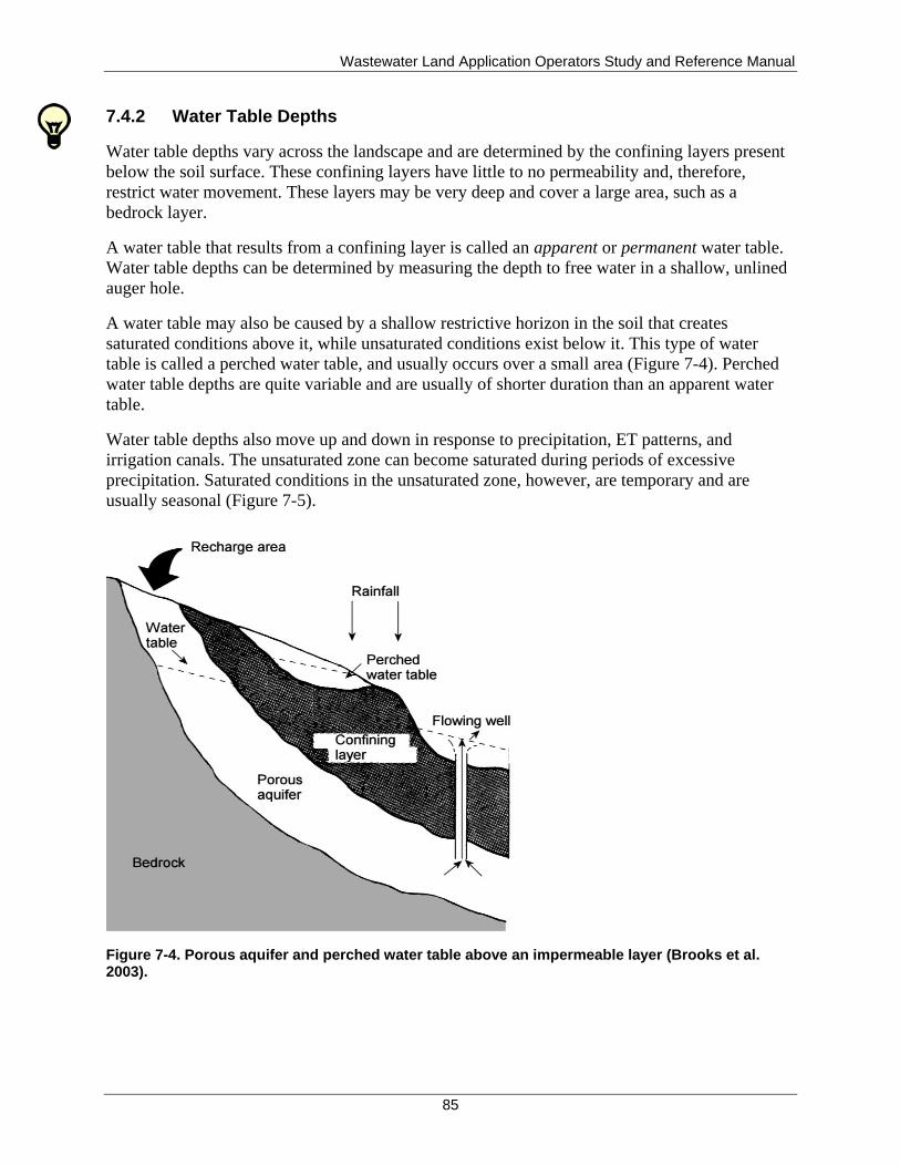
Wastewater Land Application Operators Study and Reference Manual
85
7.4.2 Water Table Depths
Water table depths vary across the landscape and are determined by the confining layers present
below the soil surface. These confining layers have little to no permeability and, therefore,
restrict water movement. These layers may be very deep and cover a large area, such as a
bedrock layer.
A water table that results from a confining layer is called an apparent or permanent water table.
Water table depths can be determined by measuring the depth to free water in a shallow, unlined
auger hole.
A water table may also be caused by a shallow restrictive horizon in the soil that creates
saturated conditions above it, while unsaturated conditions exist below it. This type of water
table is called a perched water table, and usually occurs over a small area (Figure 7-4). Perched
water table depths are quite variable and are usually of shorter duration than an apparent water
table.
Water table depths also move up and down in response to precipitation, ET patterns, and
irrigation canals. The unsaturated zone can become saturated during periods of excessive
precipitation. Saturated conditions in the unsaturated zone, however, are temporary and are
usually seasonal (Figure 7-5).
Figure 7-4. Porous aquifer and perched water table above an impermeable layer (Brooks et al. 2003).
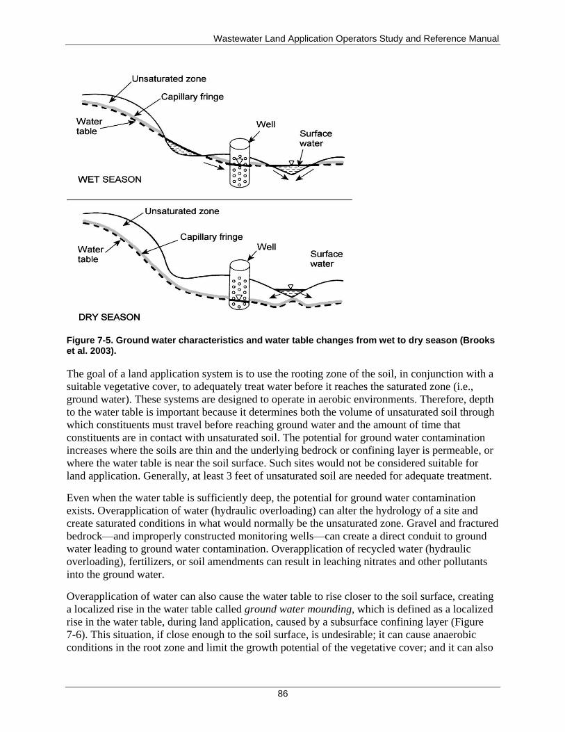
Wastewater Land Application Operators Study and Reference Manual
86
Figure 7-5. Ground water characteristics and water table changes from wet to dry season (Brooks et al. 2003).
The goal of a land application system is to use the rooting zone of the soil, in conjunction with a
suitable vegetative cover, to adequately treat water before it reaches the saturated zone (i.e.,
ground water). These systems are designed to operate in aerobic environments. Therefore, depth
to the water table is important because it determines both the volume of unsaturated soil through
which constituents must travel before reaching ground water and the amount of time that
constituents are in contact with unsaturated soil. The potential for ground water contamination
increases where the soils are thin and the underlying bedrock or confining layer is permeable, or
where the water table is near the soil surface. Such sites would not be considered suitable for
land application. Generally, at least 3 feet of unsaturated soil are needed for adequate treatment.
Even when the water table is sufficiently deep, the potential for ground water contamination
exists. Overapplication of water (hydraulic overloading) can alter the hydrology of a site and
create saturated conditions in what would normally be the unsaturated zone. Gravel and fractured
bedrock—and improperly constructed monitoring wells—can create a direct conduit to ground
water leading to ground water contamination. Overapplication of recycled water (hydraulic
overloading), fertilizers, or soil amendments can result in leaching nitrates and other pollutants
into the ground water.
Overapplication of water can also cause the water table to rise closer to the soil surface, creating
a localized rise in the water table called ground water mounding, which is defined as a localized
rise in the water table, during land application, caused by a subsurface confining layer (Figure
7-6). This situation, if close enough to the soil surface, is undesirable; it can cause anaerobic
conditions in the root zone and limit the growth potential of the vegetative cover; and it can also
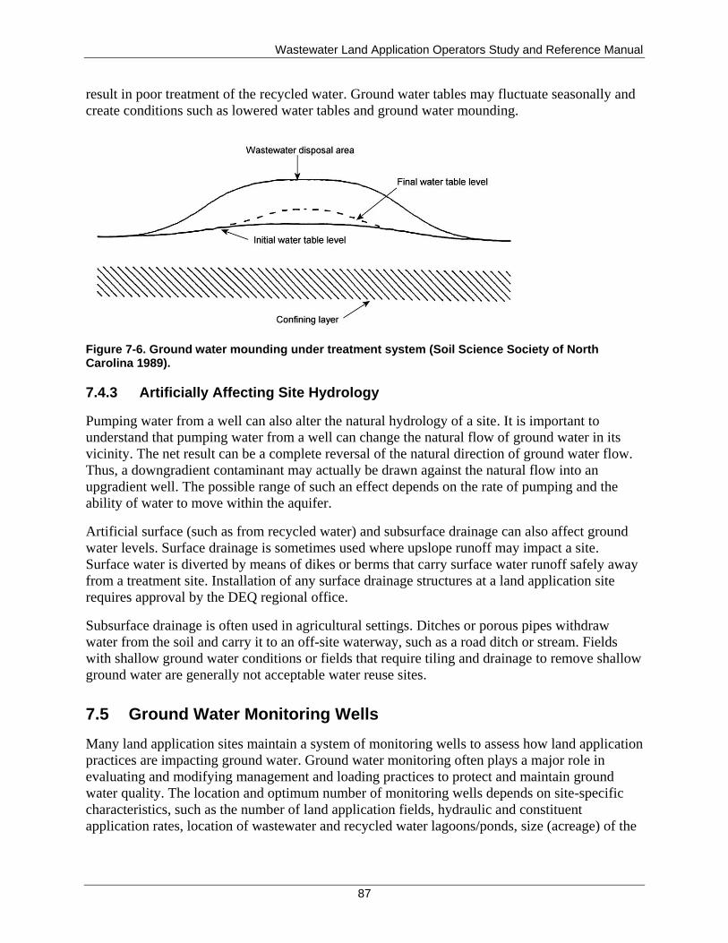
Wastewater Land Application Operators Study and Reference Manual
87
result in poor treatment of the recycled water. Ground water tables may fluctuate seasonally and
create conditions such as lowered water tables and ground water mounding.
Figure 7-6. Ground water mounding under treatment system (Soil Science Society of North Carolina 1989).
7.4.3 Artificially Affecting Site Hydrology
Pumping water from a well can also alter the natural hydrology of a site. It is important to
understand that pumping water from a well can change the natural flow of ground water in its
vicinity. The net result can be a complete reversal of the natural direction of ground water flow.
Thus, a downgradient contaminant may actually be drawn against the natural flow into an
upgradient well. The possible range of such an effect depends on the rate of pumping and the
ability of water to move within the aquifer.
Artificial surface (such as from recycled water) and subsurface drainage can also affect ground
water levels. Surface drainage is sometimes used where upslope runoff may impact a site.
Surface water is diverted by means of dikes or berms that carry surface water runoff safely away
from a treatment site. Installation of any surface drainage structures at a land application site
requires approval by the DEQ regional office.
Subsurface drainage is often used in agricultural settings. Ditches or porous pipes withdraw
water from the soil and carry it to an off-site waterway, such as a road ditch or stream. Fields
with shallow ground water conditions or fields that require tiling and drainage to remove shallow
ground water are generally not acceptable water reuse sites.
7.5 Ground Water Monitoring Wells
Many land application sites maintain a system of monitoring wells to assess how land application
practices are impacting ground water. Ground water monitoring often plays a major role in
evaluating and modifying management and loading practices to protect and maintain ground
water quality. The location and optimum number of monitoring wells depends on site-specific
characteristics, such as the number of land application fields, hydraulic and constituent
application rates, location of wastewater and recycled water lagoons/ponds, size (acreage) of the

Wastewater Land Application Operators Study and Reference Manual
88
fields, ground water depth, ground water flow characteristics, ground water uses, and the purpose
of the monitoring system.
7.5.1.1 Well Location
The location of ground water monitoring wells is important in evaluating the change in ground
water quality as it progresses through the land application site, and it allows the operator to see
how the land application activities affect ground water quality. Upgradient monitoring wells
indicate the existing ground water quality, and downgradient wells indicate the effect the land
application site has on ground water quality.
To achieve their intended purpose, monitoring wells must be located along the path of ground
water flowing underneath the land application site. Typically, at least one well is installed
hydraulically upgradient and at least two wells are installed hydraulically downgradient of the
land application site, as shown in Figure 7-7. The number of ground water monitoring wells
would be based on various factors such as the size of the reuse fields, depth and beneficial uses
of the aquifer, and proximity of ground water users and is specified in the permit.
Figure 7-7. Proper and improper locations for ground water monitoring wells (wells 1, 2, and 3 are improperly located; wells 4, 5, and 6 are properly located).
Analyses of ground water sampled from the upgradient well establishes the quality of ground
water unimpacted by the land application site (i.e., background quality), while ground water
samples from the downgradient well establish (by comparison with upgradient samples) the
impact of land application operations on ground water quality to determine compliance with
“Ground Water Quality Rule” (IDAPA 58.01.11).
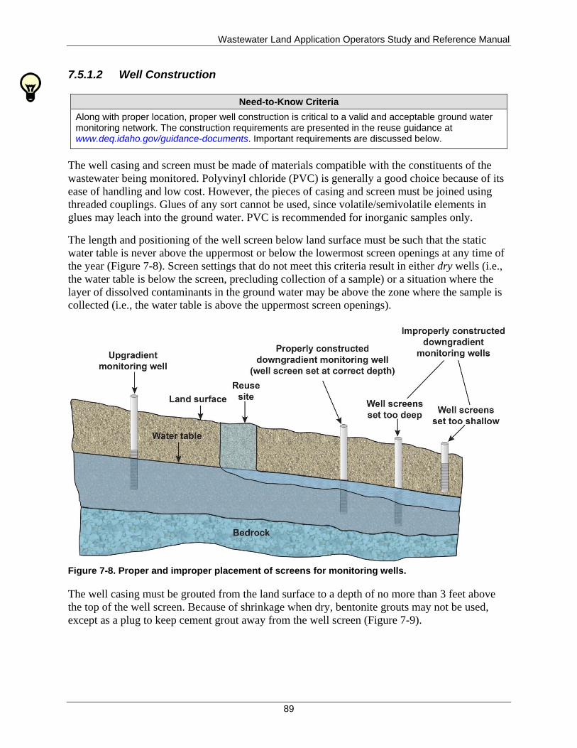
Wastewater Land Application Operators Study and Reference Manual
89
7.5.1.2 Well Construction
Need-to-Know Criteria
Along with proper location, proper well construction is critical to a valid and acceptable ground water monitoring network. The construction requirements are presented in the reuse guidance at www.deq.idaho.gov/guidance-documents. Important requirements are discussed below.
The well casing and screen must be made of materials compatible with the constituents of the
wastewater being monitored. Polyvinyl chloride (PVC) is generally a good choice because of its
ease of handling and low cost. However, the pieces of casing and screen must be joined using
threaded couplings. Glues of any sort cannot be used, since volatile/semivolatile elements in
glues may leach into the ground water. PVC is recommended for inorganic samples only.
The length and positioning of the well screen below land surface must be such that the static
water table is never above the uppermost or below the lowermost screen openings at any time of
the year (Figure 7-8). Screen settings that do not meet this criteria result in either dry wells (i.e.,
the water table is below the screen, precluding collection of a sample) or a situation where the
layer of dissolved contaminants in the ground water may be above the zone where the sample is
collected (i.e., the water table is above the uppermost screen openings).
Figure 7-8. Proper and improper placement of screens for monitoring wells.
The well casing must be grouted from the land surface to a depth of no more than 3 feet above
the top of the well screen. Because of shrinkage when dry, bentonite grouts may not be used,
except as a plug to keep cement grout away from the well screen (Figure 7-9).
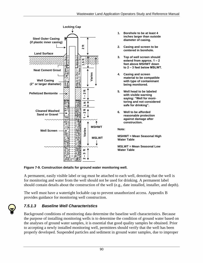
Wastewater Land Application Operators Study and Reference Manual
90
Figure 7-9. Construction details for ground water monitoring well.
A permanent, easily visible label or tag must be attached to each well, denoting that the well is
for monitoring and water from the well should not be used for drinking. A permanent label
should contain details about the construction of the well (e.g., date installed, installer, and depth).
The well must have a watertight lockable cap to prevent unauthorized access. Appendix B
provides guidance for monitoring well construction.
7.5.1.3 Baseline Well Characteristics
Background conditions of monitoring data determine the baseline well characteristics. Because
the purpose of installing monitoring wells is to determine the condition of ground water based on
the analyses of ground water samples, it is essential that good quality samples be obtained. Prior
to accepting a newly installed monitoring well, permittees should verify that the well has been
properly developed. Suspended particles and sediment in ground water samples, due to improper
1. Borehole to be at least 4inches larger than outsidediameter of casing.
2. Casing and screen to becentered in borehole.
3. Top of well screen shouldextend from approx. 1 – 2feet above MSHWT downto 2 – 3 feet below MSLWT.
4. Casing and screenmaterial to be compatiblewith type of contaminantbeing monitored.
5. Well head to be labeledwith visible warningsaying: “Well for moni-toring and not consideredsafe for drinking”.
6. Well to be affordedreasonable protectionagainst damage afterconstruction.
Note:
MSHWT = Mean Seasonal HighWater Table
MSLWT = Mean Seasonal LowWater Table
Locking Cap
2 f
t1
.5 f
t
Va
rie
s
1 –
2 f
t1
ft
1 –
2 f
tV
ari
es
MSHWT
MSLWT
2 –
3 ft
Well Screen
Cleaned Washed
Sand or Gravel
Pelletized Bentonite
Well Casing
(2” or larger diameter)
Neat Cement Grout
Land Surface
Steel Outer Casing
(if plastic inner casing)

Wastewater Land Application Operators Study and Reference Manual
91
well development, interfere with some chemical analyses and can lead to compliance problems
and additional financial outlays.
Generally wells are sampled initially after construction, prior to land application activities, to
establish a valid background concentration for constituents requiring routine monitoring.
Thereafter, monitoring frequency will be determined by the schedule specified in the permit.
7.5.1.4 Reporting Requirements
Ground water monitoring data must be reported in the annual and/or monthly or other frequency
reports. Be consistent in reporting well location and identification numbers, and designate each
well as upgradient or downgradient in relation to the land application site. Identify wells using
the serial numbers designated in the current permit.
7.6 Rapid Infiltration Basins
Rapid infiltration (RI) systems, also known as soil aquifer treatment systems, are highly
permeable infiltration basins that are operated using periods of wetting and drying cycles at set
frequencies to provide for both anaerobic and aerobic treatment of the recycled water through the
vadose zone. The drying cycles are necessary to allow the soil to re-aerate between applications
thereby allowing the aerobic microbial population that provides treatment to reestablish. The
ratio of wetting/drying in successful RI systems varies based on the soil characteristics and
treatment objectives, but it is always less than 1.0.
RI systems accomplish treatment through physical, chemical, and biological interactions in the
soil matrix. Vegetation typically has a marginal role in RI systems and is not generally utilized
by this treatment method.
RI systems shall be designed to provide even distribution of recycled water, prevent erosion, and
ensure proper operation during winter conditions in cold climate areas.
Discharge to an RI system may not exceed the hydraulic, organic, nitrogen, suspended solids, or
other limitations specified in the permit. Discharges from an RI system shall be in compliance
with the “Ground Water Quality Rule” (IDAPA 58.01.11) and “Water Quality Standards”
(IDAPA 58.01.02).
7.7 Summary
In conclusion, the soil-plant system can effectively treat wastewater constituents and prevent
them from reaching ground water if the system is properly sited, operated, and maintained. It is
important to remember that soils vary tremendously in their treatment capacity. Under some
conditions, constituents may take months or years to move from the soil surface to the ground
water. Under other conditions, constituents can flow almost directly into the ground water. Once
constituents reach the saturated zone, they are available for withdrawal from a drinking water
well or discharge to adjacent surface waters, possibly jeopardizing both public health and
environmental quality.

Wastewater Land Application Operators Study and Reference Manual
92
This page intentionally left blank for correct double-sided printing.
Wastewater Land Application Operators Study and Reference Manual
93
8 Recycled Water Disinfection and Buffer Zones
Need-to-Know Criteria
Buffer zones
Buffer zone reductions through mitigation measures
Two important aspects of any land application site are disinfection, which destroys disease-
producing organisms and buffer zones, which minimize public health impacts, nuisance
conditions, and aesthetic concerns.
8.1 Disinfection
Disinfection is generally the last form of treatment prior to land application for municipal
systems, although there may be a few industrial systems that disinfect. The purpose of
disinfection is to destroy disease-producing microorganisms or pathogens. As discussed in
section 5.3.1, pathogens can cause many illnesses, such as typhoid fever, amoebic dysentery, and
infectious hepatitis.
The disinfection process should be economical, operationally practical, and environmentally
acceptable. Three major types of disinfection are used:
Chlorination
Ultraviolet radiation
Ozone
8.1.1 Chlorination
Because of its simple feed and control procedures, its ability to disinfect water with low dosages,
and its relatively low cost, chlorination is the most prevalent form of disinfection in the United
States today. However, heightened awareness of the safety issues and environmental concerns
associated with chlorine use is decreasing its popularity.
Chlorine reacts with many compounds present in recycled water. Nitrogen compounds (including
ammonia) react with chlorine to produce chloramines. These chloramines are considered to be
relatively effective disinfectants. However, many of the compounds formed when chlorine reacts
with non-nitrogen compounds are ineffective as disinfectants.
Chlorine reacts with non-nitrogen compounds before it reacts with nitrogen compounds.
Therefore, enough chlorine must be added to react with the non-nitrogen compounds and ensure
that enough chlorine is still available for the formation of chloramines. Less chlorine is required
to disinfect a higher quality effluent than a poorer quality effluent because there are fewer
compounds with which the chlorine may react.
Chlorine dosage is the amount of chlorine that is added to a given volume of water. Chlorine
demand is the amount of chlorine that is not available as a disinfectant because of reactions with

Wastewater Land Application Operators Study and Reference Manual
94
various compounds. Chlorine residual is the amount of chlorine that is available for disinfection
after a specific contact time. Three terms are usually used in reference to chlorine residual:
Combined chlorine residual
Free chlorine residual
Total chlorine residual
Figure 8-1 is used in the following discussion. When chlorine is added to recycled water, some
of the chlorine is used in oxidizing a variety of compounds in the water and does not contribute
to chlorine residual (between points A and B). Additional chlorine then reacts with ammonia in
the water producing chloramines, contributing to the chlorine residual (between points B and C,
and referred to as the combined chlorine residual). As chlorine is added, the pH changes and
allows the destruction of the chloramines resulting in the release of nitrogen gas and nitrous
oxide to the atmosphere, reducing the combined chlorine residual (between points C and D). At
point D, most of the chloramines have been oxidized, which is called break point chlorination.
Continued addition of chlorine after the break point, will result in a free chlorine residual
increase at the same rate as the applied dosage (Qasim 1999).
Total chlorine residual is the sum of the combined chlorine residual and the free chlorine
residual. Therefore, prior to the break point, the total chorine residual is equal to the combined
chorine residual (since the free chlorine residual equals zero). After the break point, the total
chorine residual is equal to the combined chorine residual, at break point, plus the free chlorine
residual.
Figure 8-1. Chlorine residuals and the break point chlorination curve (modified from Qasim 1999).
Chlorine contact chambers are generally designed so that the chlorine injection point is below the
surface of the water to prevent volatilization. Chambers should also be designed to prevent short-
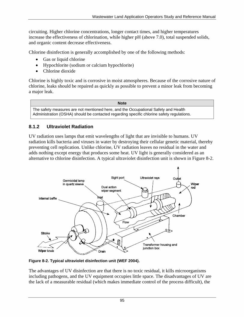
Wastewater Land Application Operators Study and Reference Manual
95
circuiting. Higher chlorine concentrations, longer contact times, and higher temperatures
increase the effectiveness of chlorination, while higher pH (above 7.0), total suspended solids,
and organic content decrease effectiveness.
Chlorine disinfection is generally accomplished by one of the following methods:
Gas or liquid chlorine
Hypochlorite (sodium or calcium hypochlorite)
Chlorine dioxide
Chlorine is highly toxic and is corrosive in moist atmospheres. Because of the corrosive nature of
chlorine, leaks should be repaired as quickly as possible to prevent a minor leak from becoming
a major leak.
Note
The safety measures are not mentioned here, and the Occupational Safety and Health Administration (OSHA) should be contacted regarding specific chlorine safety regulations.
8.1.2 Ultraviolet Radiation
UV radiation uses lamps that emit wavelengths of light that are invisible to humans. UV
radiation kills bacteria and viruses in water by destroying their cellular genetic material, thereby
preventing cell replication. Unlike chlorine, UV radiation leaves no residual in the water and
adds nothing except energy that produces some heat. UV light is generally considered as an
alternative to chlorine disinfection. A typical ultraviolet disinfection unit is shown in Figure 8-2.
Figure 8-2. Typical ultraviolet disinfection unit (WEF 2004).
The advantages of UV disinfection are that there is no toxic residual, it kills microorganisms
including pathogens, and the UV equipment occupies little space. The disadvantages of UV are
the lack of a measurable residual (which makes immediate control of the process difficult), the
Wastewater Land Application Operators Study and Reference Manual
96
lack of methods for measuring dosage, and the need for a lower suspended solids and color
concentration in order for it to be effective. For UV disinfection to be effective, the water must
be relatively clean (low turbidity) and clear; UV tubes must be kept submerged and cleaned
periodically; and organisms must come into direct contact with the UV light.
8.1.3 Ozone Disinfection
Ozone is not widely used for disinfection. Ozone is an unstable gas that is produced when
oxygen molecules are disassociated into atomic oxygen and then collide with another oxygen
molecule. Like chlorine, ozone is a strong oxidizing agent and destroys microorganisms by
attacking the cell walls. It is faster acting and more effective than chlorine in destroying viruses
and bacteria.
Because it is chemically unstable and decomposes to oxygen very rapidly, ozone must be
produced continuously and must be used as it is produced. Ozone is bubbled through the
recycled water in a closed contact chamber with fine bubble diffusers covering the bottom of the
chamber. After contact time, ozone is then collected off the top of the contact chamber and
destroyed.
Ozone is extremely irritating and can be toxic. To be effective, ozone disinfection requires high
transfer efficiency, good mixing, adequate contact time, and minimal short-circuiting in the
contactor.
The advantages of using ozone as a disinfectant include the lack of a toxic residual, an increase
in effluent dissolved oxygen levels, almost instantaneous disinfection action, and ozone’s
relative insensitivity to pH. Disadvantages include higher capital and operational costs and a lack
of reliable automatic control systems.
8.2 Buffer Zones
A buffer zone is the area beyond the perimeter of a land application field, which provides the
minimum separation needed to reduce the potential for impacts to public health and the
environment as well as minimizing nuisance conditions and aesthetic concerns. Three parts
factor into a site’s buffer zone requirements: (1) buffer zone distances to land uses of concern,
(2) posting requirements, and (3) fencing requirements. These methods limit public access and
contact with recycled water.
Land uses of concern for which DEQ has established guideline buffer zone distances are areas of
public access, surface waters, public or private drinking water supplies, and occupied dwellings.
The guideline buffer zone distances are a function of the following:
The characteristics of the land-applied water (industrial or municipal)
Level of treatment and disinfection designed for the land application site (Class A, B, C,
or D municipal effluent, industrial)
Location of the land application field (suburban/residential or rural/industrial or
residential)
Mode of irrigation (sprinkler or furrow)
Wastewater Land Application Operators Study and Reference Manual
97
For example, allowing spray mist from a land application sprinkler irrigation system to drift onto
adjoining properties has the potential to create aesthetic, nuisance, and public health impacts.
General buffer zone distance recommendations for various land uses of concern are as follows:
Inhabited dwelling: 300 feet
Private water supply well: 500 feet
Public water supply well: 1,000 feet
Public access areas: 50 feet
Permanent or intermittent surface water: 100 feet
Temporary surface water and irrigation ditches and canals: 50 feet
In general, DEQ’s guideline buffer zone distances decrease with greater disinfection
(lower total coliform counts). In addition, all buffer zone distances must comply with and
not supersede local zoning ordinances. Refer to the DEQ guidance for a detailed
discussion of buffer zones.
In section 2, the disinfection levels of the various classes of municipal recycled water are
presented in Table 2-1, Table 2-2, and Table 2-3.
The buffer zone distances specified in a reuse permit may vary from DEQ’s guidance distances
due to site-specific characteristics. For example, buffer zone distances may be reduced through
the following mitigation measures:
Establish an effective physical or vegetative barrier to reduce drift or aerosol dispersion
Use nonspray irrigation (drag tubes or equivalent apparatus)
Manage irrigation systems in a manner that prevents any spray drift towards the land use
of concern
Use runoff and/or overspray controls
Combining best management practices (BMPs) with standard buffer zone distances to help
protect drinking water supplies. Monitoring well buffer zone distances are typically less than
drinking water well buffer zones and also depend on the types of BMPs used. Monitoring well
buffer zone distances may vary from site to site and are specified in the site permit. Also note
that reuse facilities with existing or planned cross-connections or interconnections between the
recycled water system and any water supply (potable or nonpotable), or surface water, shall have
backflow prevention assemblies, devices, or methods as required by the applicable rule or as
specified in permits and approved by DEQ. Example BMPs for drinking water wellhead
protection include installing a backflow assembly and grading the ground to direct any waters
away from a wellhead.

Wastewater Land Application Operators Study and Reference Manual
98
This page intentionally left blank for correct double-sided printing.
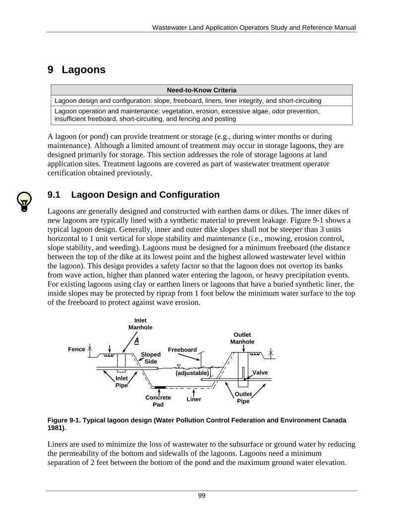
Wastewater Land Application Operators Study and Reference Manual
99
9 Lagoons
Need-to-Know Criteria
Lagoon design and configuration: slope, freeboard, liners, liner integrity, and short-circuiting
Lagoon operation and maintenance: vegetation, erosion, excessive algae, odor prevention, insufficient freeboard, short-circuiting, and fencing and posting
A lagoon (or pond) can provide treatment or storage (e.g., during winter months or during
maintenance). Although a limited amount of treatment may occur in storage lagoons, they are
designed primarily for storage. This section addresses the role of storage lagoons at land
application sites. Treatment lagoons are covered as part of wastewater treatment operator
certification obtained previously.
9.1 Lagoon Design and Configuration
Lagoons are generally designed and constructed with earthen dams or dikes. The inner dikes of
new lagoons are typically lined with a synthetic material to prevent leakage. Figure 9-1 shows a
typical lagoon design. Generally, inner and outer dike slopes shall not be steeper than 3 units
horizontal to 1 unit vertical for slope stability and maintenance (i.e., mowing, erosion control,
slope stability, and weeding). Lagoons must be designed for a minimum freeboard (the distance
between the top of the dike at its lowest point and the highest allowed wastewater level within
the lagoon). This design provides a safety factor so that the lagoon does not overtop its banks
from wave action, higher than planned water entering the lagoon, or heavy precipitation events.
For existing lagoons using clay or earthen liners or lagoons that have a buried synthetic liner, the
inside slopes may be protected by riprap from 1 foot below the minimum water surface to the top
of the freeboard to protect against wave erosion.
Figure 9-1. Typical lagoon design (Water Pollution Control Federation and Environment Canada 1981).
Liners are used to minimize the loss of wastewater to the subsurface or ground water by reducing
the permeability of the bottom and sidewalls of the lagoons. Lagoons need a minimum
separation of 2 feet between the bottom of the pond and the maximum ground water elevation.
Access
Road
Inlet
Manhole
Freeboard Fence
Inlet
Pipe
Sloped
Side
Outlet
Manhole
Outlet
Pipe
Valve (adjustable)
Liner Concrete
Pad
Wastewater Land Application Operators Study and Reference Manual
100
The typical materials used for liners are synthetic membranes, compacted clay, and bentonite.
New installations typically use high density polyethylene (HDPE) or buried PVC liners. Clay
and bentonite liners require submergence in water to retain their sealing characteristics. If
exposed and dried, clay and bentonite liners may develop cracks and lose their ability to provide
a good seal.
Design and operating standards allow seepage rates from lagoons. As such, lagoons are required
to be periodically seepage rate tested to evaluate liner integrity. Lagoon seepage above DEQ
performance criteria generally requires repair, replacement, or abandonment of the lagoon.
Municipal wastewater lagoons must meet facility-specific seepage rates corresponding to the
date of construction (or major modification) every 10 years after initial testing. Industrial facility
seepage testing is required by permit and its frequency of testing is based on the permit. Lagoons
must be seepage tested if a change in liner condition occurs that affects its permeability,
including but not limited to, liner repair below the high water line, liner replacement, lagoon
dewatering of soil-lined lagoons, which results in desiccation of the soil liner, seal installation, or
earthwork affecting liner integrity. Recycled water enters and leaves a lagoon through inlet and
outlet pipes. Inlet structures should be located so that water is distributed evenly in the lagoon. If
water is gravity fed to the lagoon, a concrete pad or riprap is often placed at the end of the inlet
pipe to protect the lagoon liner. If the lagoon is used for chlorine treatment, the outlet pipe is
located as far as possible from the inlet pipe to increase chlorine detention time and to prevent
short-circuiting (a condition where some of the water in a lagoon travels faster than the rest of
the water, between the inlet and outlet pipes). Short-circuiting is especially a problem in lagoons
that are designed to allow for a specific chlorine contact time (the amount of time chlorine must
be allowed to react with the water prior to discharge and reuse).
The following factors are used to determine the volume of lagoon storage capacity that is
required:
1. If the land application system is designed for growing season only application, the lagoon
is designed for storage of effluent throughout the nongrowing season.
2. If the land application system is designed with a nongrowing season application
allowance, storage may be necessary for periods of extreme cold temperatures, which can
prevent application due to freezing problems in the irrigation system, frozen soils, or ice
buildup on the application site.
3. If land application is not possible due to harvesting or heavy precipitation events.
4. If an alternative discharge point such as a National Pollutant Discharge Elimination
System (NPDES) permit or rapid infiltration basin is available.
Other design considerations for lagoons include the following:
Multiple cells to provide access during maintenance
Proximity to surface waters and drinking water wells
Potential for odor generation, aeration for odor reduction, and siting
Permanent stilling wells for seepage testing
Wastewater Land Application Operators Study and Reference Manual
101
9.2 Lagoon Operation and Maintenance
Regardless of how well-designed, lagoons will not perform to their optimum potential unless
properly operated and maintained. Inspections and sampling should be conducted on a routine
basis to determine if any problems are apparent. Routine operation and maintenance practices
should address and control the following conditions and situations:
Emergent (rooted) plants
Suspended vegetation
Erosion
Excessive algae
Odor production
Insufficient freeboard
Short-circuiting, if chlorine treatment is a component of the storage lagoon
Sludge depth and removal
Not running aerators as designed and/or required
In addition, other basic management steps are both recommended and required. These steps
include posting and maintaining warning signs and fencing to discourage unauthorized access
(from people and livestock) and protect public health and safety.
9.2.1 Vegetation
Controlling vegetation around lagoons is important. Weeds and grasses on dams and dikes
provide sheltered areas for insects and burrowing animals, interfere with the establishment and
maintenance of a desirable vegetative cover, and hinder visual inspection of dikes. Trees and
other deep-rooting vegetation can impair the structural integrity of lagoon dikes. Regular
mowing and weeding are required to avoid these problems.
Rooted plants growing on the bottom of the lagoon (emergent growth) and suspended vegetation
in lagoons takes up valuable space, provides a breeding ground for potential vectors, such as
mosquitoes, and hinders pond circulation. In addition, dead vegetation can contribute to BOD
levels, reduce dissolved oxygen, and cause odors.
Emergent growth will occur when sunlight is able to reach the lagoon bottom in older lagoons
with earthen bottoms or lagoons with a buried synthetic liner. Emergent growth can be controlled
by the following:
Immediate removal of young plants (including roots)
Drowning weeds by raising the water level and preventing sunlight from reaching the
plants
By installing pond liners
As a last resort, using herbicides (which should only be used with the approval of the
DEQ and taking into consideration impacts to the land application fields)
Vegetation, such as duckweed and algae can occur in any lagoon, regardless of depth. Often
mistaken for algae, duckweed floats on a lagoon surface and has long hair-like roots that hang
down into the water. It grows rapidly and can cover the entire surface of a lagoon if not
controlled. If suspended vegetation is a problem, it should be skimmed off with rakes or other
Wastewater Land Application Operators Study and Reference Manual
102
tools or mechanically harvested. As a last resort, a herbicide can be used by adhering to the
precautions outlined above. If not removed, vegetation may plug the irrigation system.
Ducks eat duckweed (hence, the name) and may control a light growth of suspended vegetation.
Fecal waste from ducks and other waterfowl, however, can contribute BOD to the lagoon and
increase coliform levels. Depending on the required disinfection level, the attraction of
waterfowl to a lagoon may seriously impact the water quality. Disinfection downstream of the
lagoon may be necessary in some cases to achieve the required water quality levels.
9.2.2 Erosion
Erosion can wash away clay liner material on inside banks or create cracks and crevices in outer
banks. Both situations reduce the structural integrity of lagoon dikes and can result in leaks and
dike failure. Erosion can be caused by wave action, surface runoff from precipitation, holes dug
by burrowing animals, access by wildlife, lack of proper vegetation on outside slopes (lagoon
dikes), steep slopes, or poor maintenance.
Slope stabilization through the installation of riprap or broken concrete along banks and dikes
can minimize erosion and limit weed growth. However, this practice cannot be used for exposed
synthetic liners.
Diversion ditches and proper grading around the lagoon may be used to divert surface water
away from the lagoon. Burrowing animals, such as gophers, moles, ground squirrels, and
groundhogs, should be trapped and removed. Burrowed holes should be repaired immediately to
prevent erosion.
9.2.3 Excessive Algae
Excessive algae growth can create serious problems. Algae blooms die off as suddenly as they
appear, blocking sunlight, and the dead vegetation can cause foul odors. The die-off of algae
blooms also causes a very high BOD loading, which reduces dissolved oxygen levels, and the
lagoon may become anaerobic or septic and cause odor problems.
A specific type of algae that can be problematic is blue-green algae (cyanobacteria). A bloom
(rapid growth) of blue-green algae can be caused by organic overloading, nutrient overloading,
high water temperatures, or stagnant conditions and foul odors.
Blue-green algae are photosynthetic bacteria that grow in fresh water lakes, ponds, and wetlands,
as well as wastewater lagoons. They usually occur only in small numbers and are so small they
are invisible to the casual observer.
When a bloom occurs, huge numbers of algae grow and accumulate on the surface of the lagoon,
to the point where the surface of the water resembles thick pea soup, often blue-green in color.
Although these blooms occur naturally, water bodies that have been enriched with plant nutrients
from municipal, industrial, or agricultural sources are particularly susceptible to these growths.
Blue-green algal blooms are unsightly, but more important, blue-green algal blooms can be toxic
if ingested by wildlife, livestock, or people. Blue-green algae produce neurotoxins that affect the
nervous and respiratory systems and hepatotoxins that affect the liver function.
Wastewater Land Application Operators Study and Reference Manual
103
If blue-green algal blooms are suspected, they should be treated with caution. One of the first
signs of toxin contamination in a water body is the presence of stressed, sick, or dead wildlife or
waterfowl. Contact DEQ or the local health district if you suspect a problem. Water suspected of
being contaminated with toxic strains of blue-green algae can be sampled and tested for toxicity.
Algae mats should be broken up and dispersed or physically removed like duckweed. Algae can
also be controlled by physical, chemical, and biological means, such as the following:
Lagoon covers (artificial or natural) eliminate sunlight, photosynthesis, and vegetative
growth.
Aeration or mixing removes carbon dioxide from the water and reduces plant growth.
Shock chlorination at high doses for short duration and at a lower chlorine dose for
longer duration have both been used successfully in controlling algae.
Copper sulfate is the most common chemical used to control algae.
Nontoxic dyes to reduce sunlight penetration in the water.
Note
When considering any chemical or biological means of algae control, the WWLA operator must ensure that the action is approved by the DEQ and is not a violation of permit conditions.
9.2.4 Odor Prevention
Some lagoons can produce odors from time to time, depending on the water quality of the stored
water and how the ponds are maintained and operated. If odors are a problem or anticipated to be
a problem, an odor management plan must be submitted to and approved by DEQ.
The odor management plan should cover water treatment systems, land application facilities,
lagoons, and other operations associated with the facility. The plan should include specific
design considerations, operation and maintenance procedures, and management practices to be
employed to minimize the potential for or limit odors. The plan should also include procedures to
respond to an odor incident if one occurs.
Odors related to lagoons may be caused by the following:
Storage of recycled water with a high organic content
Stagnant conditions or long detention times of water in storage
Lagoon turnover due to seasonal temperature changes. This causes a vertical movement
of the lagoon contents causing the lower anaerobic zone to move towards the surface
Organic overloading (may be caused by the accumulation of dead vegetation or algae) of
the lagoon
Most odors in the lagoon water column are caused due to anaerobic conditions, which generate
odorous gases such as hydrogen sulfide and mercapans.
9.2.5 Insufficient Freeboard
A properly designed lagoon system will provide adequate freeboard or safety volume to prevent
an overflow from the lagoon. Overflow from lagoons, for any reason, is a violation of state rules
and is subject to enforcement action. Allowing a lagoon to reach its maximum storage capacity

Wastewater Land Application Operators Study and Reference Manual
104
before the start of the nongrowing season does not leave room for storing excess precipitation
during extended wet periods. In the late summer and early fall, lagoons are typically pumped
down as far as possible.
In Idaho, lagoons are designed to have a minimum of 3 feet of permanent freeboard unless they
are under 50,000 gallons/day for which 2 feet may be acceptable. Under normal operations, the
freeboard space will not be used for water storage. However, under some conditions, the
freeboard space may be encroached upon:
Extremely high precipitation event.
High flow into the lagoon from situations such as rapid population growth, inflow and
infiltration problems, or in industrial systems, plant upsets or unusual operations resulting
in greater generation of recycled water.
Inability to lower lagoon volume to minimum levels prior to the winter storage season.
If a situation arises that could result in approaching a lagoon overflow, or as the
minimum freeboard level is encroached upon, contact the DEQ regional office to
evaluate the situation and to determine what actions and approvals may be needed.
9.2.6 Short-Circuiting
Short-circuiting is a condition that occurs when some of the water in a lagoon or basin travels
faster than the rest of the flowing water, typically between the inlet and outlet pipes. This
problem can be caused by poor design, sludge accumulation in the lagoon bottom, vegetation
that hinders lagoon circulation, and temperature gradients in the water column (lagoon turnover).
Short-circuiting is a bigger concern for lagoons that perform treatment or are used for chlorine
disinfection. It is of less of a concern for lagoons used solely for storage. However, if the short-
circuiting causes stagnant conditions in a portion of the lagoon, it can cause odor problems
depending on the water quality. Short-circuiting can be verified by the use of dye tests and may
be corrected or prevented by using curtains or baffles to redirect flow, relocating inlet and outlet
pipes, controlling vegetation, and removing excessive sludge deposits from the lagoon.
9.2.7 Sludge Accumulation and Removal
Sludge is the semisolid or solid material in sewage that separates out during treatment. Sludge
levels should always be evaluated as too much sludge can displace water volume and create
channeling or short-circuiting of the wastewater and create problems that cause inadequate
wastewater treatment. It is not expected that storage lagoons will accumulate a significant
amount of sludge since the storage lagoon generally follows after treatment. The sludge
accumulation rate is important for planning and determining the need for sludge removal. Sludge
accumulation is affected by many variables, including hydraulic and organic loading
pretreatment, temperature, and lagoon design.
A sludge inventory assesses the amount and locations of solids in the lagoon. Many options are
available for sludge removal, and a state-approved sludge removal plan is often requried prior to
sludge removal. The removed sludge is subject to state and federal rules, and the lagoon owner is
generally considered the responsible party legally as the generator of the sludge. Municipal and
industrial sludge may have different state and federal rule requirements. Sludge may contain
pathogens, nutrients, and heavy metals. Sludge may be disposed of or beneficially used for soil

Wastewater Land Application Operators Study and Reference Manual
105
augmentation. Treated sludge is called biosolids. Biosolids when treated are safe for beneficial
use for soil augmentation, which include use for crop nutrients. Sludge may also be disposed of
at land fills if the land fill will accept it. Requirements for land fill disposal include dewatering
and testing for heavy metals.

Wastewater Land Application Operators Study and Reference Manual
106
This page intentionally left blank for correct double-sided printing.
Wastewater Land Application Operators Study and Reference Manual
107
10 Distribution Network and Devices
Need-to-Know Criteria
Pump discharge: flowmeters and counters
Distribution network and devices: fittings, sprinklers, solid set irrigation equipment, and center pivots
Operational issues: as-built plans, backflow devices, system pressure, and system discharge flows
The WWLA operator needs a basic understanding of pumps and their controls as well as an
understanding of distribution networks and their devices. In most cases, WWLA operators will
be operating and maintaining equipment and systems that were designed and installed by
someone else. WWLA operators will have greater success in operating and maintaining a
distribution system that was properly designed and installed, but even a good design does not
guarantee that recycled water will be properly applied. Poor operation can adversely affect the
performance of a well-designed system. Conversely, careful operation of a poorly designed
system can sometimes provide a good performing land application system.
10.1 Pumps and Controls
10.1.1 Pumps
A pump is a mechanical device that imparts energy to liquids to move the liquids from one
location to another. Generally irrigation pumps operate on the following principals:
Air is exhausted from the working chamber.
Atmospheric pressure forces water (or another liquid) into the chamber.
The pump mechanism forces the water out of the chamber, creating a partial vacuum.
Additional water fills the chamber to repeat this cycle.
The general concepts associated with pumps and controls are found in Appendix D.
10.1.2 Backflow Prevention Assemblies and Devices
Reuse facilities with existing or planned cross-connections or interconnections between the
recycled water system and any water supply (potable or nonpotable), shall have approved
backflow prevention assemblies or devices as required by the applicable rule or regulation and
approved by DEQ.
Approved backflow prevention assemblies are a category of backflow preventers that
have been evaluated and certified to meet certain standards. Third party approval
organizations certify assemblies to meet certain material, design, and performance
standards. They must meet performance standards that include pressure loss, head loss,
and flow requirements. Assemblies are mechanical backflow preventers designed to be
tested and repaired in-line (AWWA 2012).
Devices are mechanical backflow preventers that do not meet the specific approval
requirements of an assembly. Devices are generally nontestable and not repairable in-line
(AWWA 2012).
Wastewater Land Application Operators Study and Reference Manual
108
There shall be no connection between drinking water distribution systems or ground water wells
and any pipes, pumps, hydrants, water-loading stations, or tanks whereby unsafe water or other
contaminating materials may be discharged or drawn into a public water system or ground water
well. The WWLA operator is responsible through backflow prevention assemblies and devices to
take reasonable and prudent measures to protect the water system against contamination and
pollution from cross connections. An approved backflow assembly is strongly recommended to
be installed on the discharge from an irrigation well to prevent ground water contamination.
The assemblies shall be adequately maintained, shall be tested annually by a certified backflow
assembly tester, and repaired or replaced as necessary to maintain operational status. Records of
backflow assembly test results, repairs, and replacements shall be kept at the reuse facility along
with other operational records and shall be discussed in the annual report and made available for
inspection by DEQ. Other approved means of backflow prevention, such as siphons and air-gap
structures that cannot be tested, shall be maintained in operable order.
Backflow prevention may be required on a case-by-case basis, as determined by DEQ, to isolate
different classes of recycled water.
10.1.3 Alarms and Timers
Alarms are controls with visual and/or audible signals that indicate that a condition exists in the
system requiring the WWLA operator's attention. The alarms vary from a simple high water
level alarm to a multiple alarm system. The most common and necessary is the high water alarm.
High water alarms can be activated using the same ON/OFF controls used to sense water-level
changes. Alarms may be needed for other parameters such as temperatures, pump, power, and
seal failures.
Timers are devices that allow the WWLA operator to control pumps or controls in specified
ways at predetermined times. Run cycle timers repeatedly open and close contacts according to
preset time cycles while pump run timers are helpful in calculating the volume of discharged
water.
10.1.4 Counters
Counters measure pump activity related to flow. Counters provide flow indication for timer
panels. A counter can be used to add up the number of times the pump has been activated, or for
run counters, used to calculate the volume of discharged water.
10.1.5 Flowmeters
Flowmeters are instruments for measuring the amount (flow volume) or rate (velocity) of water
flow. It is necessary to know the flow rate in a treatment system so that adjustments can be made
to pumping rates, chlorination rates, and other processes in the system. Water flow rates must
also be known for calculating hydraulic and constituent loadings at a land application site.
Elapsed time meters are used to record the amount of time each pump runs. This is a good way to
monitor the hours per day that a pump runs. One elapsed time meter is used per pump. If a
flowmeter is not installed or operational on the discharge line, WWLA operators might be able to
use, under certain conditions a combination of pump run timers, knowledge of the operating
Wastewater Land Application Operators Study and Reference Manual
109
characteristics of the pump, and the manufacturer’s pump performance curve to estimate the flow
(or volume) of applied water.
Flow-measuring devices must be periodically calibrated to ensure a known pump discharge rate
and ensure their continued precision and accuracy. Most manufacturers and dealer
representatives will offer a service and maintenance agreement with a flowmeter for its periodic
calibration. Calibration is recommended per manufacturer specified frequencies, and when
conditions or damage (e.g., lightning) has occurred that could affect the accuracy of the meter.
Comparing flow measurement against other methods of flow estimation can also help to calibrate
pump discharge rates. For example, total flow in a pump cycle may be estimated by knowing the
discharge rate from a sprinkler based on nozzle size and pressure (which gives gallons per
minute) and multiplying this value by the total pump run time.
Another standard to check against is pump drawdown in a tank or wet well, or lagoon level
drawdown. To estimate flow rate by the pump drawdown method, other inflows and outflows to
the tank or lagoon must be shutoff or precisely measured.
The WWLA operator should use all appropriate techniques to help with flow management and
calibration for a land application system.
10.2 Distribution Network and Devices
To ensure the appropriate amount of water is uniformly applied at a land application site,
WWLA operators must be familiar with common types of irrigation application devices
(sprinklers), irrigation system design, correct pressure settings, and other distribution system
operating issues.
10.2.1 Pipes and Fittings
10.2.1.1 Pipes
A piping system consists of the pipes, fittings, and appurtenances within which a fluid flows.
WWLA operators should be familiar with pipes, connections, and valves. General information is
found in Appendix E.
10.2.1.2 Fittings
Pipe fittings are joints or connectors between pieces of pipe. Examples are elbows that alter the
direction of a pipe; tees and crosses connect a branch with a main; plugs and caps close an end;
and bushings, diminishers, or reducing sockets couple two pipes of different dimensions.
Pipe cleanouts should be used whenever recycled water has a solids content that causes the
potential for solids buildup and clogging in piping. Cleanouts are also advised at sharp turns in
piping, such as elbows, where water tends to slow down. A pipe cleanout is typically a wye
fitting (a pipe fitting with three branches positioned in one plane in a pattern of the letter Y) that
is installed several feet up-flow from the appropriate area to be cleaned, typically at elbows or
sharp turns. The dead end of the wye is at the ground surface or above for easy access and is
capped off with a threaded plug. This access must be protected from equipment and traffic. The
Wastewater Land Application Operators Study and Reference Manual
110
cleanout allows the WWLA operator to clean the piping with plumbing snakes, augers, or water
pressure cleaners.
Thrust blocking is used in irrigation systems, using moderate-to-high water pressures to protect
the distribution system from damage that could be caused by water pressure. Thrust blocking is
used at all points at which water flow either changes direction (such as tees and elbows) or
comes to a dead end (ends of laterals or field valves). The thrust block, which is typically a mass
of concrete, must lie against natural ground to offer the most protection. Pipe excavation for
repair at any of these points is likely to encounter concrete thrust blocks, which must be replaced
when replacing pipe or fittings where water changes direction.
10.2.2 Irrigation Application Devices (Sprinklers)
Sprinklers, drip emitters, and other devices are used to distribute water to the land application
fields. Many people consider the application devices (sprinklers) to be the heart of the irrigation
system, but a well designed and properly functioning pumping system is critical to the operation
of the sprinklers. However, most WWLA operators will spend much of their time dealing with
sprinkler management, maintenance, and repair. Sprinkler maintenance and operation is a key
component of successfully managing a land application system.
Many types of irrigation application devices are available. Most are not designed for recycled
water containing solids, but some have been adapted for this use. Many irrigation devices
function well where recycled water is very dilute and has few solids or chemicals. It is beyond
the scope of this manual to discuss all types of equipment available. The WWLA operator should
be familiar with the basic terms describing irrigation equipment and the factors that affect the
operation of that equipment. When purchasing irrigation equipment, always notify the dealer that
the equipment will be used in a recycled water setting.
Some common types of irrigation application devices (sprinklers) are described below:
Nozzle—The part of the sprinkler where the water discharge occurs. Important factors
are nozzle type (plastic, brass, taper bore, or ring) and nozzle size at the opening (in
inches).
Full circle sprinkler—A sprinkler that turns 360 degrees and wets a total circle. These
sprinklers are used in the interior and exterior positions of land application fields.
Partial circle or partial turn sprinkler—A special sprinkler that allows the WWLA
operator to direct discharge to a select portion of the field. Devices such as clips or
threaded stops cause the sprinkler to rotate part circle (less than 360 degrees). These
sprinklers are often used to prevent irrigation into buffers, roadways, ditches, or problem
areas in the field. Note that using partial turn sprinklers, without changing other
parameters, such as nozzle size or pressure, results in an increased water application rate.
For example, a half turn sprinkler with the same settings as a full turn sprinkler will apply
two times as much water per hour to the area it irrigates. Partial turn sprinklers must be
operated very carefully to avoid ponding and runoff.
Gun—Usually refers to a large sprinkler with nozzle opening exceeding one-half inch. A
gun is usually mounted onto a permanent riser of 2-inch pipe size or larger, a traveling
gun cart, or the distal end of a center pivot system.
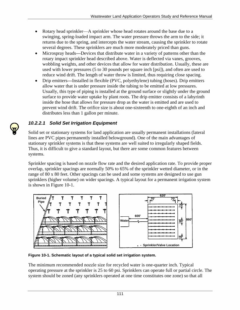
Wastewater Land Application Operators Study and Reference Manual
111
Rotary head sprinkler—A sprinkler whose head rotates around the base due to a
swinging, spring-loaded impact arm. The water pressure throws the arm to the side; it
returns due to the spring, and intercepts the water stream, causing the sprinkler to rotate
several degrees. These sprinklers are much more moderately priced than guns.
Microspray heads—Devices that distribute water in a variety of patterns other than the
rotary impact sprinkler head described above. Water is deflected via vanes, grooves,
wobbling weights, and other devices that allow for water distribution. Usually, these are
used with lower pressures (5 to 30 pounds per square inch [psi]), and often are used to
reduce wind drift. The length of water throw is limited, thus requiring close spacing.
Drip emitters—Installed in flexible (PVC, polyethylene) tubing (hoses). Drip emitters
allow water that is under pressure inside the tubing to be emitted at low pressures.
Usually, this type of piping is installed at the ground surface or slightly under the ground
surface to provide water uptake by plant roots. The drip emitter consists of a labyrinth
inside the hose that allows for pressure drop as the water is emitted and are used to
prevent wind drift. The orifice size is about one-sixteenth to one-eighth of an inch and
distributes less than 1 gallon per minute.
10.2.2.1 Solid Set Irrigation Equipment
Solid set or stationary systems for land application are usually permanent installations (lateral
lines are PVC pipes permanently installed belowground). One of the main advantages of
stationary sprinkler systems is that these systems are well suited to irregularly shaped fields.
Thus, it is difficult to give a standard layout, but there are some common features between
systems.
Sprinkler spacing is based on nozzle flow rate and the desired application rate. To provide proper
overlap, sprinkler spacings are normally 50% to 65% of the sprinkler wetted diameter, or in the
range of 80 x 80 feet. Other spacings can be used and some systems are designed to use gun
sprinklers (higher volume) on wider spacings. A typical layout for a permanent irrigation system
is shown in Figure 10-1.
Figure 10-1. Schematic layout of a typical solid set irrigation system.
The minimum recommended nozzle size for recycled water is one-quarter inch. Typical
operating pressure at the sprinkler is 25 to 60 psi. Sprinklers can operate full or partial circle. The
system should be zoned (any sprinklers operated at one time constitutes one zone) so that all
Buried Pipe
Water
600'
Pipe
620' 70' 70'
70'
80'
70'
- Sprinkler/Valve Location
860'

Wastewater Land Application Operators Study and Reference Manual
112
sprinklers are operating on about the same amount of rotation to achieve uniform application.
Gun sprinklers typically have higher application rates; therefore, adjacent guns should not be
operated at the same time (referred to as head to head). Most permanent systems use PVC plastic
irrigation pipe for mains, submains, and laterals and either 1-inch galvanized steel or Schedule
40 or 80 PVC risers near the ground surface where an aluminum quick coupling riser valve is
installed (Figure 10-2). In grazing conditions, all risers must be protected (stabilized) if left in the
field with animals.
The advantages of fixed irrigation equipment include the following:
Flexible irrigation rates
Suitability for irregularly shaped fields
Suitability for tree crops
Disadvantages of fixed irrigation equipment include the following:
High capital costs
Limited use for row crops
Figure 10-2. Typical spray head for a fixed system.
10.2.2.2 Mobile Irrigation Equipment
Mobile or traveling sprinkler systems are either cable-tow, hose-drag travelers, center pivot, or
linear-move systems.
3/4 inch
Galvanized Steel
Control Valve
Automatic
Drain Valve
1 Sq. Ft.
Washed Stone
1 Inch Feeder Pipe
1.5 Feet
Minimum Cover
3.0 Feet
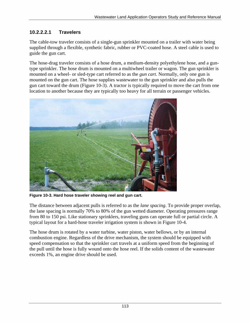
Wastewater Land Application Operators Study and Reference Manual
113
10.2.2.2.1 Travelers
The cable-tow traveler consists of a single-gun sprinkler mounted on a trailer with water being
supplied through a flexible, synthetic fabric, rubber or PVC-coated hose. A steel cable is used to
guide the gun cart.
The hose-drag traveler consists of a hose drum, a medium-density polyethylene hose, and a gun-
type sprinkler. The hose drum is mounted on a multiwheel trailer or wagon. The gun sprinkler is
mounted on a wheel- or sled-type cart referred to as the gun cart. Normally, only one gun is
mounted on the gun cart. The hose supplies wastewater to the gun sprinkler and also pulls the
gun cart toward the drum (Figure 10-3). A tractor is typically required to move the cart from one
location to another because they are typically too heavy for all terrain or passenger vehicles.
Figure 10-3. Hard hose traveler showing reel and gun cart.
The distance between adjacent pulls is referred to as the lane spacing. To provide proper overlap,
the lane spacing is normally 70% to 80% of the gun wetted diameter. Operating pressures range
from 80 to 150 psi. Like stationary sprinklers, traveling guns can operate full or partial circle. A
typical layout for a hard-hose traveler irrigation system is shown in Figure 10-4.
The hose drum is rotated by a water turbine, water piston, water bellows, or by an internal
combustion engine. Regardless of the drive mechanism, the system should be equipped with
speed compensation so that the sprinkler cart travels at a uniform speed from the beginning of
the pull until the hose is fully wound onto the hose reel. If the solids content of the wastewater
exceeds 1%, an engine drive should be used.
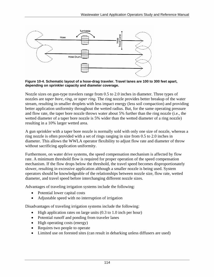
Wastewater Land Application Operators Study and Reference Manual
114
Figure 10-4. Schematic layout of a hose-drag traveler. Travel lanes are 100 to 300 feet apart, depending on sprinkler capacity and diameter coverage.
Nozzle sizes on gun-type travelers range from 0.5 to 2.0 inches in diameter. Three types of
nozzles are taper bore, ring, or taper ring. The ring nozzle provides better breakup of the water
stream, resulting in smaller droplets with less impact energy (less soil compaction) and providing
better application uniformity throughout the wetted radius. But, for the same operating pressure
and flow rate, the taper bore nozzle throws water about 5% further than the ring nozzle (i.e., the
wetted diameter of a taper bore nozzle is 5% wider than the wetted diameter of a ring nozzle)
resulting in a 10% larger wetted area.
A gun sprinkler with a taper bore nozzle is normally sold with only one size of nozzle, whereas a
ring nozzle is often provided with a set of rings ranging in size from 0.5 to 2.0 inches in
diameter. This allows the WWLA operator flexibility to adjust flow rate and diameter of throw
without sacrificing application uniformity.
Furthermore, on water drive systems, the speed compensation mechanism is affected by flow
rate. A minimum threshold flow is required for proper operation of the speed compensation
mechanism. If the flow drops below the threshold, the travel speed becomes disproportionately
slower, resulting in excessive application although a smaller nozzle is being used. System
operators should be knowledgeable of the relationships between nozzle size, flow rate, wetted
diameter, and travel speed before interchanging different nozzle sizes.
Advantages of traveling irrigation systems include the following:
Potential lower capital costs
Adjustable speed with no interruption of irrigation
Disadvantages of traveling irrigation systems include the following:
High application rates on large units (0.3 to 1.0 inch per hour)
Potential runoff and ponding from traveler lanes
High operating costs (energy)
Requires two people to operate
Limited use on forested sites (can result in debarking unless diffusers are used)
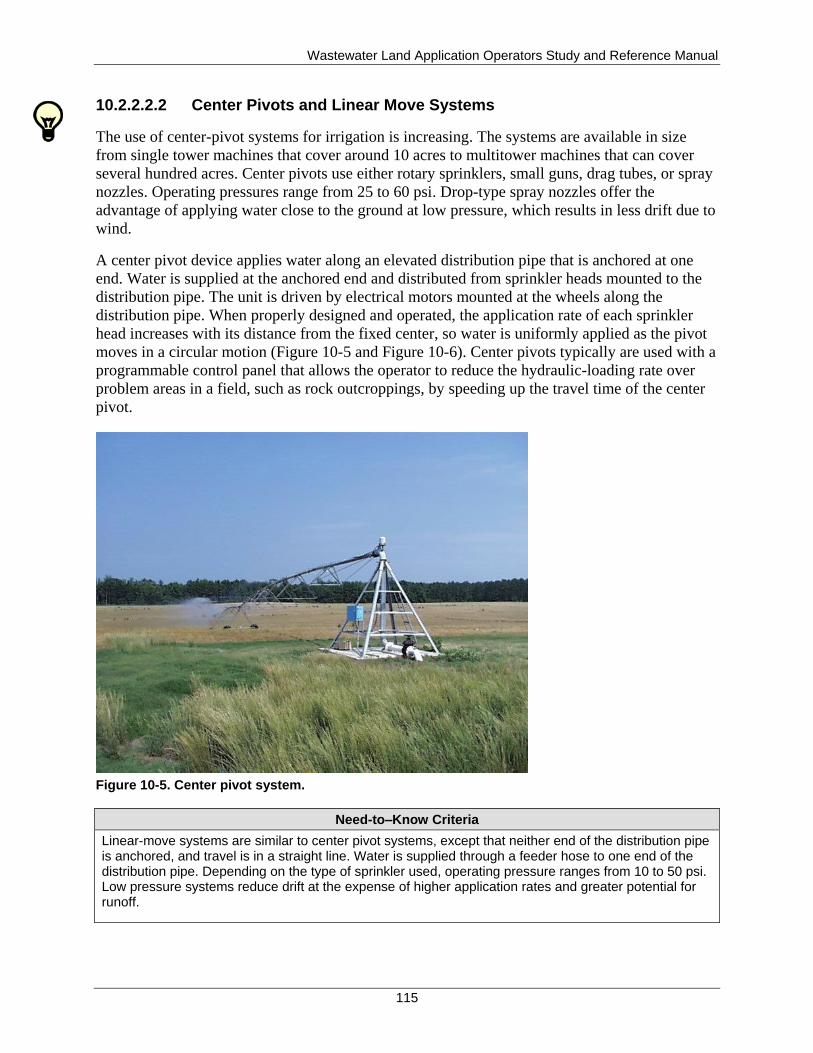
Wastewater Land Application Operators Study and Reference Manual
115
10.2.2.2.2 Center Pivots and Linear Move Systems
The use of center-pivot systems for irrigation is increasing. The systems are available in size
from single tower machines that cover around 10 acres to multitower machines that can cover
several hundred acres. Center pivots use either rotary sprinklers, small guns, drag tubes, or spray
nozzles. Operating pressures range from 25 to 60 psi. Drop-type spray nozzles offer the
advantage of applying water close to the ground at low pressure, which results in less drift due to
wind.
A center pivot device applies water along an elevated distribution pipe that is anchored at one
end. Water is supplied at the anchored end and distributed from sprinkler heads mounted to the
distribution pipe. The unit is driven by electrical motors mounted at the wheels along the
distribution pipe. When properly designed and operated, the application rate of each sprinkler
head increases with its distance from the fixed center, so water is uniformly applied as the pivot
moves in a circular motion (Figure 10-5 and Figure 10-6). Center pivots typically are used with a
programmable control panel that allows the operator to reduce the hydraulic-loading rate over
problem areas in a field, such as rock outcroppings, by speeding up the travel time of the center
pivot.
Figure 10-5. Center pivot system.
Need-to–Know Criteria
Linear-move systems are similar to center pivot systems, except that neither end of the distribution pipe is anchored, and travel is in a straight line. Water is supplied through a feeder hose to one end of the distribution pipe. Depending on the type of sprinkler used, operating pressure ranges from 10 to 50 psi. Low pressure systems reduce drift at the expense of higher application rates and greater potential for runoff.
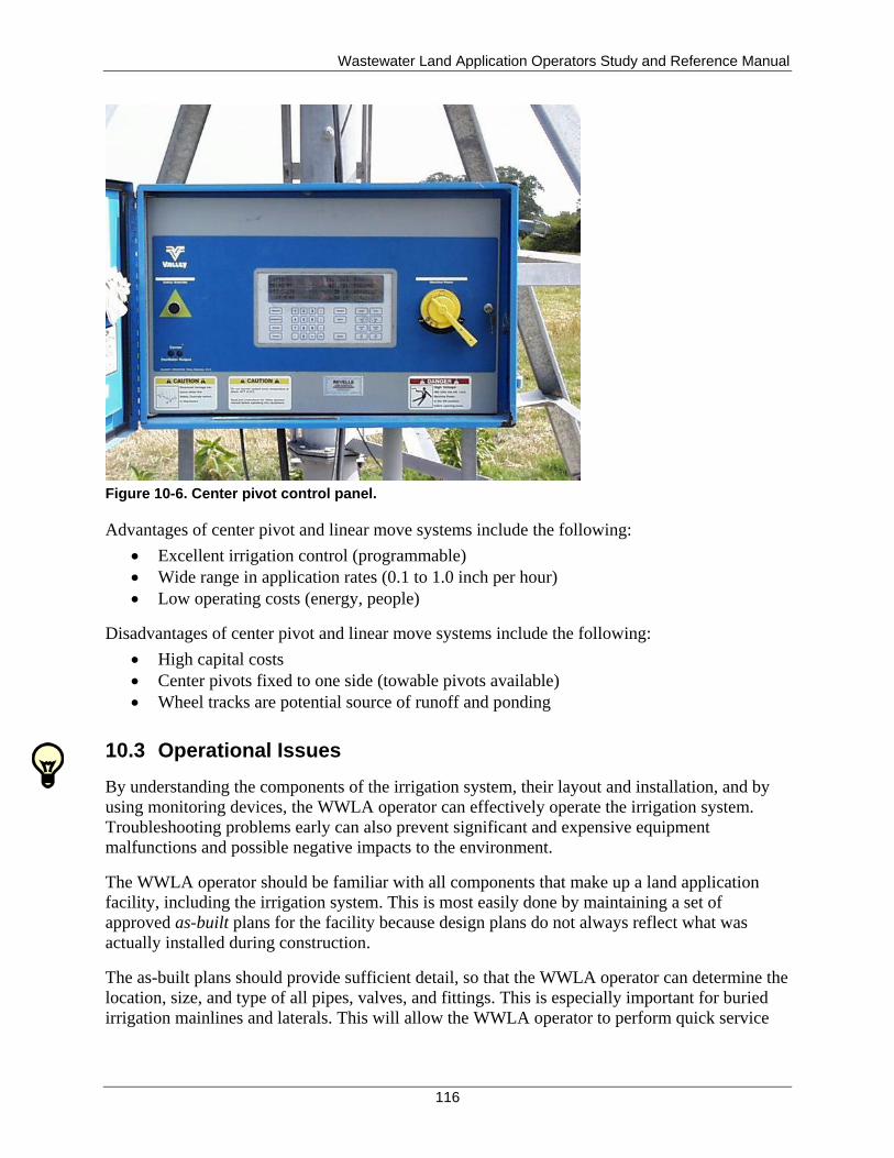
Wastewater Land Application Operators Study and Reference Manual
116
Figure 10-6. Center pivot control panel.
Advantages of center pivot and linear move systems include the following:
Excellent irrigation control (programmable)
Wide range in application rates (0.1 to 1.0 inch per hour)
Low operating costs (energy, people)
Disadvantages of center pivot and linear move systems include the following:
High capital costs
Center pivots fixed to one side (towable pivots available)
Wheel tracks are potential source of runoff and ponding
10.3 Operational Issues
By understanding the components of the irrigation system, their layout and installation, and by
using monitoring devices, the WWLA operator can effectively operate the irrigation system.
Troubleshooting problems early can also prevent significant and expensive equipment
malfunctions and possible negative impacts to the environment.
The WWLA operator should be familiar with all components that make up a land application
facility, including the irrigation system. This is most easily done by maintaining a set of
approved as-built plans for the facility because design plans do not always reflect what was
actually installed during construction.
The as-built plans should provide sufficient detail, so that the WWLA operator can determine the
location, size, and type of all pipes, valves, and fittings. This is especially important for buried
irrigation mainlines and laterals. This will allow the WWLA operator to perform quick service
Wastewater Land Application Operators Study and Reference Manual
117
and repair and keep spare parts on hand. If as-built plans are not on site, a set may be obtained
from the design engineer for the facility.
If both recycled water and supplemental irrigation water are applied to the land application
fields, determine if the supplemental irrigation water supply is directly connected to the recycled
water distribution system. If so, a DEQ-approved backflow prevention device must be installed
to protect the quality of the fresh irrigation water supply. If the supplemental irrigation water
comes from two sources (well and surface water) an approved backflow prevention assembly
should be installed between the irrigation well and surface water delivery system. An approved
backflow prevention assembly is not required at the interconnection of a canal and a feeder
irrigation ditch.
The WWLA operator must be familiar with pump discharge rates and the factors that affect
discharge rates as described earlier. Knowledge of operating pressures in the field is crucial to
understanding and evaluating water application flow rates and system efficiency. It is valuable to
measure pressure at several locations, also known as pressure surveys. They are useful for
identifying bottlenecks in the irrigation distribution system and can aid in designing system
modifications or additions. Measuring pressure at the discharge point (sprinkler or gun) provides
the most information about the actual rate of application.
Most guns have a fitting where a pressure gauge can be easily mounted. Rotary impact sprinklers
can be fitted with a pressure gauge by installing a tee in the sprinkler riser. On an irrigation
system or zone with multiple sprinklers, several pressure readings across the field give the best
picture. However, at least one reading near midfield and one near the sprinklers installed at
higher elevations provide valuable pressure information for the system. The pressure at the
sprinkler head dictates the flow rate (gallons per minute) through that sprinkler. Significant
elevation changes within one field or zone can result in higher discharge pressures and rates in
the lower portions of the field.
Knowledge of pump pressure and field pressure can help the WWLA operator determine if
pumps are running efficiently. An operating pressure that is less than the design pressure may
indicate wearing of the pump or sprinklers. Gathering baseline data can also help determine
when pipes are beginning to clog. Blockages, as well as broken or separated pipes, can cause
pressure reductions in the distribution system. These problems often result in extremely wet
areas that will be obvious to the WWLA operator. Wet and soggy areas near valves and fittings
may indicate that the pipe has been damaged or improperly installed, such that leaks are causing
the soil in the area to remain saturated.
Close monitoring of pumping rates by use of flowmeters or pump operating data will help with
operational and maintenance decisions at the facility. Pump, piping, and sprinkler wear can be
predicted with accurate flow records. These records can also help the WWLA operator determine
if infiltration and inflow from the collection system are contributing to the recycled water stream.
Accurate flow monitoring is important for compliance with state record keeping requirements,
and may indicate when a system expansion is necessary.
If actual applied recycled water flows exceed the irrigation system design flow, then a detailed
examination of the pumping and irrigation systems (sprinkler design and layout map) should be
conducted and necessary steps should be taken to maintain compliance with the reuse permit.
Wastewater Land Application Operators Study and Reference Manual
118
Pump monitoring records, such as pump run time and number of pump cycles, can be used to
monitor pump efficiency and proper working of float switches or relays. Following an inspection
and maintenance schedule to identify and replace worn components will help a system to operate
at its design flow.
In summary, the WWLA operator should maintain detailed records of all equipment and
operational parameters at the facility. In conjunction with a detailed set of as-built plans,
operational and maintenance decisions can be made to provide long equipment life and efficient
overall system operation. Additional information regarding the operation and maintenance of
land application equipment is presented in section 13.4.
Wastewater Land Application Operators Study and Reference Manual
119
11 Irrigation Systems Operations and Scheduling
Need-to-Know Criteria
Irrigation scheduling; basic soil-water relationships, estimating soil-water content, feel method, and checkbook method
Determining how much to irrigate; operational considerations
System calibration
This section discusses the operation and scheduling of the land application irrigation system. As
discussed, land application facilities consist of many components, from the influent pipe to the
soil-crop system, and everything in between. The WWLA operator must understand the entire
system for it to perform properly. The WWLA operator does not need to be a specialist in all
facets of land application system design, soil science, or crop science. However, the WWLA
operator needs to understand day-to-day management and be able to identify those situations that
call for technical assistance.
A main function of a land application system is to provide final treatment while protecting the
quality of the land application environment. Another function is to provide beneficial reuse of
the recycled water and nutrients to produce a crop. One way to minimize adverse environmental
impacts at a land application site is to maintain a healthy system for final treatment. The WWLA
operator must ensure that all aspects of the system are properly operated and maintained. Soil
and crops must be protected so that continued use of the land application site is ensured. Surface
and ground water must be protected to ensure the integrity of these resources. Sites must be
protected from poor field operations that destroy soil structure. They must also be protected from
overapplication of metals, nutrients, salts, and other constituents that can adversely affect the
soil-crop system.
11.1 Irrigation Scheduling
Proper land application involves using water management strategies to ensure that water is
applied at the proper time and in the correct amounts. This balance achieves the following:
Optimizes the timing of nutrient application to match crop uptake
Maintains adequate storage in the lagoon, if a lagoon is part of the land application
system, to handle all inflows of water and precipitation without overtopping
Applies recycled water at a rate and amount so that no direct surface runoff or deep
percolation below the root zone occurs and provides the irrigation requirement for the
crop throughout the growing season
The criteria listed above create an important framework for the operation and maintenance of a
land application system. A responsible WWLA operator must understand how recycled water
should be managed, have knowledge of the capacity of the system to store and apply recycled
water when appropriate, and make prudent management decisions concerning when and how
much recycled water to land apply. For a land application system, this decision-making process
is called irrigation scheduling.
Wastewater Land Application Operators Study and Reference Manual
120
Irrigation scheduling is the process of answering two questions:
1. When to irrigate?
2. How much to irrigate?
Effective irrigation scheduling requires knowledge of soil properties, soil moisture content, crop
type, climate, irrigation equipment, and estimated daily/weekly precipitation deficit. Monitoring
soil moisture will help prevent runoff and leaching of recycled water (including nutrients) to the
ground water. Monitoring soil moisture is important to ensure that land application of recycled
water is conducted within permit limits. This section discusses the interaction of these factors
and how to incorporate them into an effective irrigation schedule. Keep in mind that hydraulic
and constituent loadings are established by the facility permit for both the growing and
nongrowing seasons (if nongrowing season application is allowed in the permit) and should not
be exceeded. The WWLA operator must comply with these permitted amounts when planning
irrigation events. This section also focuses on irrigation scheduling for growing season
operations.
11.1.1 Determining When to Irrigate
The following questions should be answered when deciding to irrigate:
1. Can the recycled water be applied to an actively growing crop (or will a crop be planted
or actively start growing within 30 days)?
2. Is there a nutrient deficit remaining for this crop being grown?
3. Are the fields dry enough to be irrigated?
If the answer to all three questions above is yes, then an irrigation event should be scheduled.
The answer to Question 1 should be obvious to the WWLA operator for growing season
operations. Question 2 requires knowledge of the amount of nutrients that should be applied for
the crop grown and the amount that has already been applied.
Determining the answer to Question 3, whether or not the field is dry enough to be irrigated, is
not always obvious. Soil saturation can be determined by observing free water in an auger hole.
However, other methods can determine whether a soil is saturated or not. If the soil is not
saturated, the following methods can be used to determine how dry the soil is:
A subjective method that involves feeling the soil
Objective methods using soil-moisture measuring devices
An accounting approach (checkbook method) to estimate soil-water content
11.1.2 Basic Soil-Water Relationships
Before attempting to measure or estimate soil-water content, recall the basic soil-water
relationships discussed in section 6.4. Important terms to remember include saturation, field
capacity, wilting point, gravitational water, and plant-available water (PAW).
Not all of the water added to soil is necessarily retained in the soil for use by plants. Water
containing nutrients should be applied to soil so that the nutrients remain in the root zone for
uptake by the crop. Water not retained in the root zone may transport constituents, resulting in a
pollution threat to either surface water, ground water, or both.
Wastewater Land Application Operators Study and Reference Manual
121
To use soil-water measurements for irrigation scheduling, it is important to distinguish between
two categories of soil-water:
1. Gravitational water—The water in the soil that is free to drain or move by the force of
gravity. Gravitational water is computed as the volume of water in the soil between
saturation and field capacity. When gravitational water is present in the root zone, the soil
is too wet to be irrigated.
2. PAW—The amount of water held in the soil that is available to plants. It is computed as
the difference between the water content at field capacity (referred to as upper limit water
content) and the permanent wilting point (often referred to as the lower limit water
content). Although water is theoretically available to plants between these two limits, if
the soil water available to the plants falls below the maximum allowable depletion
(MAD), there will be a loss in yield or crop quality due to moisture stress. Irrigation
should be scheduled to maintain the water content of the soil above the MAD to avoid
crop moisture stress losses. MAD is defined as the portion of PAW that can be used by
the crop at specified stages of crop development that will not cause yield or quality loss
due to moisture stress. If the soil-water content is above field capacity, gravitational
water is present and irrigation should be delayed until the soil-water content nears the
MAD under normal operating conditions. Figure 11-1 depicts the relationship between
these soil-water terms.
Soil texture influences the portion of the soil pore volume that can be occupied by gravitational
water or PAW; therefore, it is important to know the soil texture to determine how much water
should be applied.
The amount of PAW that exists in the soil at any given time is commonly expressed as the depth
of water per unit depth of soil. Typical units are inches of PAW per foot of soil depth. PAW,
AWC in the root zone, can be estimated for various soil textural classes by using the United
States Department of Agriculture, Soil Conservation Service, soil survey reports. Estimates are
done by taking the AWC (inches of water per inch of soil) value and multiplying it by the total
inches of soil root depth which will yield the number of inches of PAW for the soil root depth.
PAW values for various soil types may be compared to each other by calculating the PAW for a
common soil depth, typically 1 foot. This can be done by multiplying the AWC (in inches of
water per inch of soil) value by 12 inches per foot (in./ft), which will yield the number of inches
of PAW per foot of soil. This basis of comparison estimates a range from less than 0.2 inch of
PAW per foot of soil for coarse sandy soils to nearly 2 inches of PAW per foot of soil for silty
clay and clay soils (Table 11-1).
At the start of irrigation, the water content in the soil should be at or lower (drier) than field
capacity (upper limit). The difference between the existing water content and the field capacity
water content is the maximum amount that should be irrigated. The drier the soil, the more water
that can be safely applied per application, provided this amount does not exceed the required
nutrient application rate or violate any other permit conditions. Determining the water content of
the soil indicates whether the soil is dry enough to be irrigated and if so, how much water can be
applied.
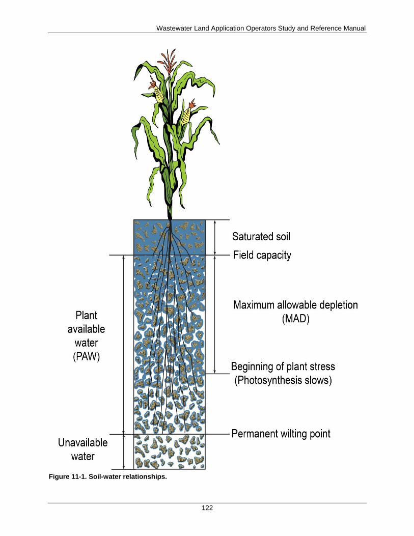
Wastewater Land Application Operators Study and Reference Manual
122
Figure 11-1. Soil-water relationships.
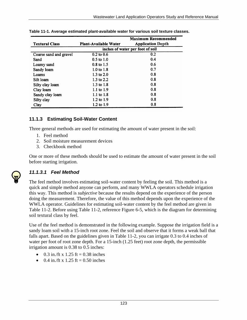
Wastewater Land Application Operators Study and Reference Manual
123
Table 11-1. Average estimated plant-available water for various soil texture classes.
11.1.3 Estimating Soil-Water Content
Three general methods are used for estimating the amount of water present in the soil:
1. Feel method
2. Soil moisture measurement devices
3. Checkbook method
One or more of these methods should be used to estimate the amount of water present in the soil
before starting irrigation.
11.1.3.1 Feel Method
The feel method involves estimating soil-water content by feeling the soil. This method is a
quick and simple method anyone can perform, and many WWLA operators schedule irrigation
this way. This method is subjective because the results depend on the experience of the person
doing the measurement. Therefore, the value of this method depends upon the experience of the
WWLA operator. Guidelines for estimating soil-water content by the feel method are given in
Table 11-2. Before using Table 11-2, reference Figure 6-5, which is the diagram for determining
soil textural class by feel.
Use of the feel method is demonstrated in the following example. Suppose the irrigation field is a
sandy loam soil with a 15-inch root zone. Feel the soil and observe that it forms a weak ball that
falls apart. Based on the guidelines given in Table 11-2, you can irrigate 0.3 to 0.4 inches of
water per foot of root zone depth. For a 15-inch (1.25 feet) root zone depth, the permissible
irrigation amount is 0.38 to 0.5 inches:
0.3 in./ft x 1.25 ft = 0.38 inches
0.4 in./ft x 1.25 ft = 0.50 inches
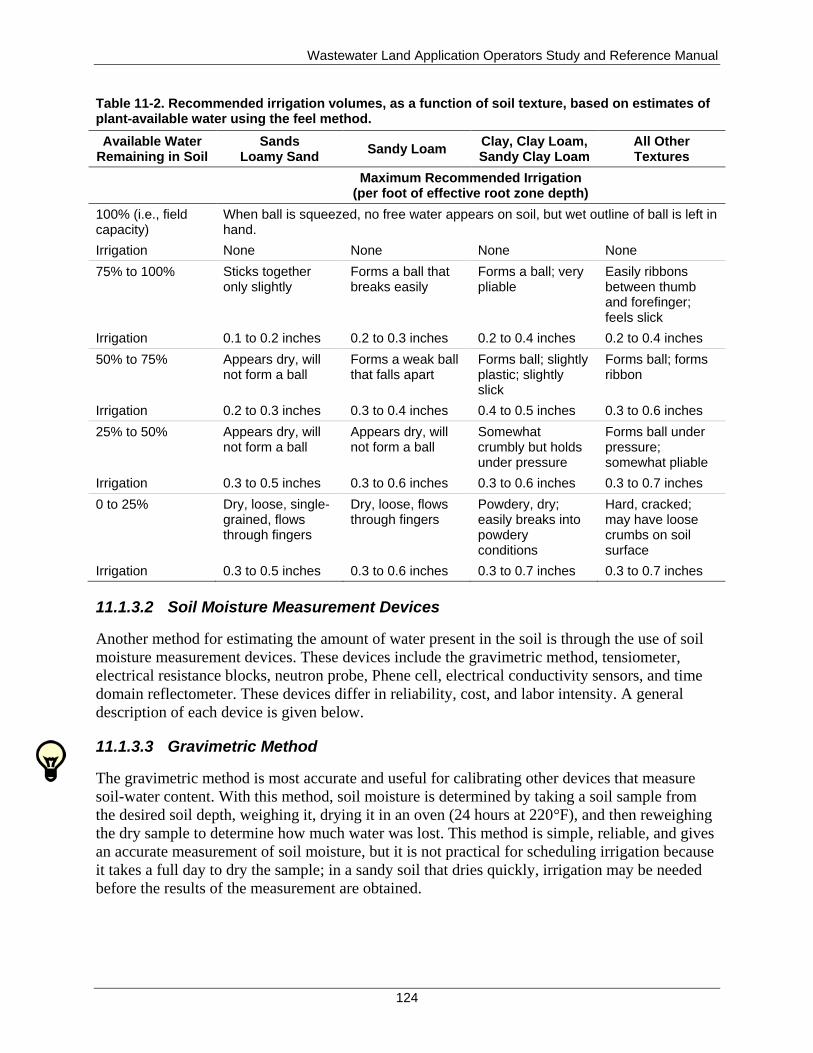
Wastewater Land Application Operators Study and Reference Manual
124
Table 11-2. Recommended irrigation volumes, as a function of soil texture, based on estimates of plant-available water using the feel method.
Available Water Remaining in Soil
Sands Loamy Sand
Sandy Loam Clay, Clay Loam, Sandy Clay Loam
All Other Textures
Maximum Recommended Irrigation (per foot of effective root zone depth)
100% (i.e., field capacity)
When ball is squeezed, no free water appears on soil, but wet outline of ball is left in hand.
Irrigation None None None None
75% to 100% Sticks together only slightly
Forms a ball that breaks easily
Forms a ball; very pliable
Easily ribbons between thumb and forefinger; feels slick
Irrigation 0.1 to 0.2 inches 0.2 to 0.3 inches 0.2 to 0.4 inches 0.2 to 0.4 inches
50% to 75% Appears dry, will not form a ball
Forms a weak ball that falls apart
Forms ball; slightly plastic; slightly slick
Forms ball; forms ribbon
Irrigation 0.2 to 0.3 inches 0.3 to 0.4 inches 0.4 to 0.5 inches 0.3 to 0.6 inches
25% to 50% Appears dry, will not form a ball
Appears dry, will not form a ball
Somewhat crumbly but holds under pressure
Forms ball under pressure; somewhat pliable
Irrigation 0.3 to 0.5 inches 0.3 to 0.6 inches 0.3 to 0.6 inches 0.3 to 0.7 inches
0 to 25% Dry, loose, single-grained, flows through fingers
Dry, loose, flows through fingers
Powdery, dry; easily breaks into powdery conditions
Hard, cracked; may have loose crumbs on soil surface
Irrigation 0.3 to 0.5 inches 0.3 to 0.6 inches 0.3 to 0.7 inches 0.3 to 0.7 inches
11.1.3.2 Soil Moisture Measurement Devices
Another method for estimating the amount of water present in the soil is through the use of soil
moisture measurement devices. These devices include the gravimetric method, tensiometer,
electrical resistance blocks, neutron probe, Phene cell, electrical conductivity sensors, and time
domain reflectometer. These devices differ in reliability, cost, and labor intensity. A general
description of each device is given below.
11.1.3.3 Gravimetric Method
The gravimetric method is most accurate and useful for calibrating other devices that measure
soil-water content. With this method, soil moisture is determined by taking a soil sample from
the desired soil depth, weighing it, drying it in an oven (24 hours at 220°F), and then reweighing
the dry sample to determine how much water was lost. This method is simple, reliable, and gives
an accurate measurement of soil moisture, but it is not practical for scheduling irrigation because
it takes a full day to dry the sample; in a sandy soil that dries quickly, irrigation may be needed
before the results of the measurement are obtained.
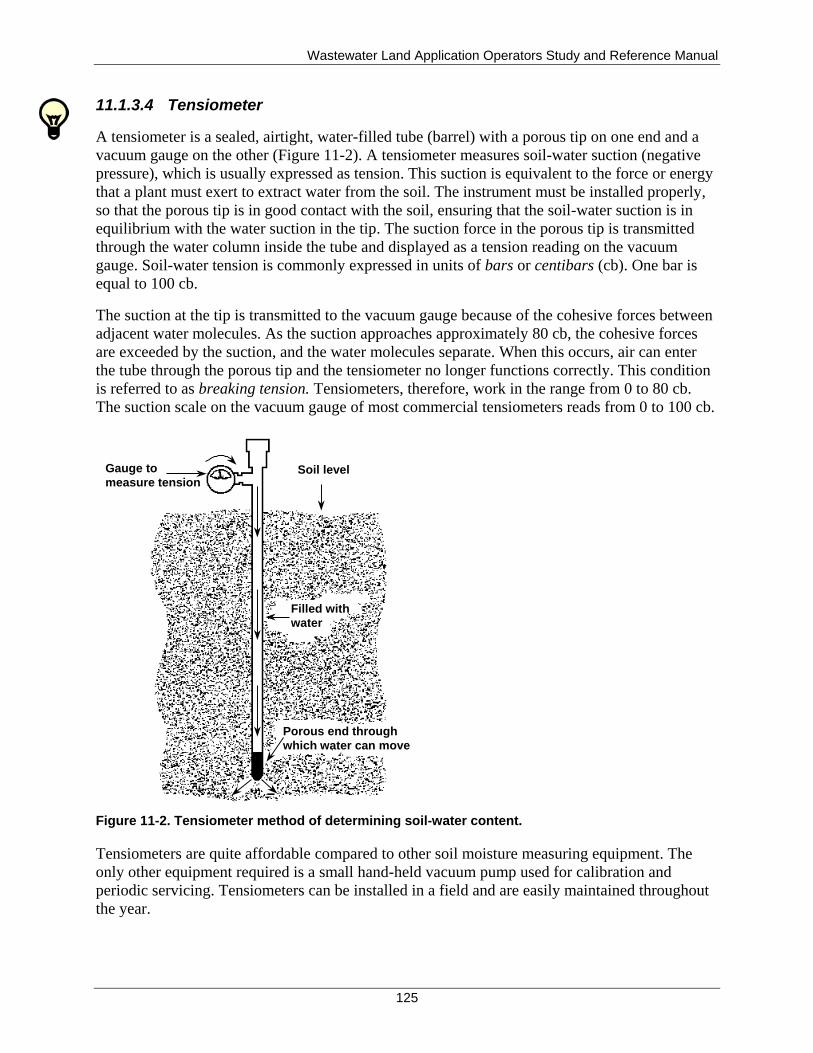
Wastewater Land Application Operators Study and Reference Manual
125
11.1.3.4 Tensiometer
A tensiometer is a sealed, airtight, water-filled tube (barrel) with a porous tip on one end and a
vacuum gauge on the other (Figure 11-2). A tensiometer measures soil-water suction (negative
pressure), which is usually expressed as tension. This suction is equivalent to the force or energy
that a plant must exert to extract water from the soil. The instrument must be installed properly,
so that the porous tip is in good contact with the soil, ensuring that the soil-water suction is in
equilibrium with the water suction in the tip. The suction force in the porous tip is transmitted
through the water column inside the tube and displayed as a tension reading on the vacuum
gauge. Soil-water tension is commonly expressed in units of bars or centibars (cb). One bar is
equal to 100 cb.
The suction at the tip is transmitted to the vacuum gauge because of the cohesive forces between
adjacent water molecules. As the suction approaches approximately 80 cb, the cohesive forces
are exceeded by the suction, and the water molecules separate. When this occurs, air can enter
the tube through the porous tip and the tensiometer no longer functions correctly. This condition
is referred to as breaking tension. Tensiometers, therefore, work in the range from 0 to 80 cb.
The suction scale on the vacuum gauge of most commercial tensiometers reads from 0 to 100 cb.
Figure 11-2. Tensiometer method of determining soil-water content.
Tensiometers are quite affordable compared to other soil moisture measuring equipment. The
only other equipment required is a small hand-held vacuum pump used for calibration and
periodic servicing. Tensiometers can be installed in a field and are easily maintained throughout
the year.
Soil level
Filled with
water
Porous end through
which water can move
Gauge to
measure tension
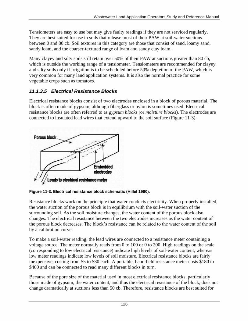
Wastewater Land Application Operators Study and Reference Manual
126
Tensiometers are easy to use but may give faulty readings if they are not serviced regularly.
They are best suited for use in soils that release most of their PAW at soil-water suctions
between 0 and 80 cb. Soil textures in this category are those that consist of sand, loamy sand,
sandy loam, and the coarser-textured range of loam and sandy clay loam.
Many clayey and silty soils still retain over 50% of their PAW at suctions greater than 80 cb,
which is outside the working range of a tensiometer. Tensiometers are recommended for clayey
and silty soils only if irrigation is to be scheduled before 50% depletion of the PAW, which is
very common for many land application systems. It is also the normal practice for some
vegetable crops such as tomatoes.
11.1.3.5 Electrical Resistance Blocks
Electrical resistance blocks consist of two electrodes enclosed in a block of porous material. The
block is often made of gypsum, although fiberglass or nylon is sometimes used. Electrical
resistance blocks are often referred to as gypsum blocks (or moisture blocks). The electrodes are
connected to insulated lead wires that extend upward to the soil surface (Figure 11-3).
Figure 11-3. Electrical resistance block schematic (Hillel 1980).
Resistance blocks work on the principle that water conducts electricity. When properly installed,
the water suction of the porous block is in equilibrium with the soil-water suction of the
surrounding soil. As the soil moisture changes, the water content of the porous block also
changes. The electrical resistance between the two electrodes increases as the water content of
the porous block decreases. The block’s resistance can be related to the water content of the soil
by a calibration curve.
To make a soil-water reading, the lead wires are connected to a resistance meter containing a
voltage source. The meter normally reads from 0 to 100 or 0 to 200. High readings on the scale
(corresponding to low electrical resistance) indicate high levels of soil-water content, whereas
low meter readings indicate low levels of soil moisture. Electrical resistance blocks are fairly
inexpensive, costing from $5 to $30 each. A portable, hand-held resistance meter costs $180 to
$400 and can be connected to read many different blocks in turn.
Because of the pore size of the material used in most electrical resistance blocks, particularly
those made of gypsum, the water content, and thus the electrical resistance of the block, does not
change dramatically at suctions less than 50 cb. Therefore, resistance blocks are best suited for
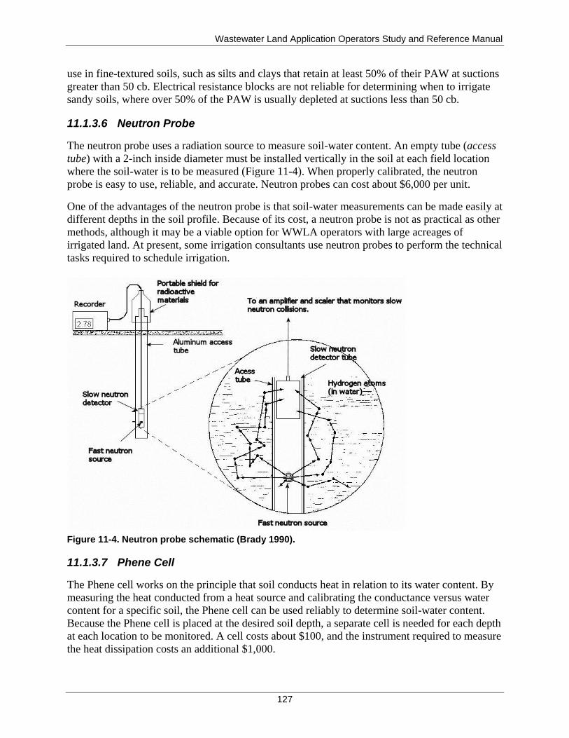
Wastewater Land Application Operators Study and Reference Manual
127
use in fine-textured soils, such as silts and clays that retain at least 50% of their PAW at suctions
greater than 50 cb. Electrical resistance blocks are not reliable for determining when to irrigate
sandy soils, where over 50% of the PAW is usually depleted at suctions less than 50 cb.
11.1.3.6 Neutron Probe
The neutron probe uses a radiation source to measure soil-water content. An empty tube (access
tube) with a 2-inch inside diameter must be installed vertically in the soil at each field location
where the soil-water is to be measured (Figure 11-4). When properly calibrated, the neutron
probe is easy to use, reliable, and accurate. Neutron probes can cost about $6,000 per unit.
One of the advantages of the neutron probe is that soil-water measurements can be made easily at
different depths in the soil profile. Because of its cost, a neutron probe is not as practical as other
methods, although it may be a viable option for WWLA operators with large acreages of
irrigated land. At present, some irrigation consultants use neutron probes to perform the technical
tasks required to schedule irrigation.
Figure 11-4. Neutron probe schematic (Brady 1990).
11.1.3.7 Phene Cell
The Phene cell works on the principle that soil conducts heat in relation to its water content. By
measuring the heat conducted from a heat source and calibrating the conductance versus water
content for a specific soil, the Phene cell can be used reliably to determine soil-water content.
Because the Phene cell is placed at the desired soil depth, a separate cell is needed for each depth
at each location to be monitored. A cell costs about $100, and the instrument required to measure
the heat dissipation costs an additional $1,000.
Wastewater Land Application Operators Study and Reference Manual
128
For irrigating small acreages, the total cost of using the Phene cell is less than that of the neutron
probe. For large acreages, the neutron probe may be more cost effective.
11.1.3.8 Time Domain Reflectometer
The time domain reflectometer is a device developed to measure soil-water content. Two parallel
rods or stiff wires are inserted into the soil to the depth at which the average water content is
desired. The rods are connected to an instrument that sends an electromagnetic pulse (or wave)
of energy along the rods. The rate at which the wave of energy is conducted into the soil and
reflected back to the soil surface is directly related to the average water content of the soil. One
instrument can be used for hundreds of pairs of rods. The time domain reflectometer is easy to
use and reliable, however, it costs around $8,000 per unit.
11.1.3.9 Selecting the Appropriate Device
In general, tensiometers and electrical resistance blocks offer the best combination of cost-
effectiveness and reliability for measuring soil-water content. Tensiometers are best suited for
sandy, sandy loam, and loamy soil textures, while electrical resistance blocks work best in silty
or clayey soils. Manufacturers of these devices provide calibration charts and recommended
ranges for traditional fresh water irrigation. Be aware that the calibration curves and
recommendations supplied by the manufacturer for these devices were developed for general
conditions and are not adequate for specific soil conditions and fields. Also be aware that
recycled water objectives and recommendations are different from fresh water recommendations.
For irrigating with recycled water, results are better if all soil-water measuring devices used are
calibrated for the major soils you are irrigating.
11.1.3.10 Checkbook Method
The checkbook method is an accounting approach for estimating how much soil-water content
remains in the effective root zone based on water inputs and outputs—like a daily balance on a
bank account based on deposits and withdrawals. The inputs are the precipitation that is stored in
the root zone and land-applied recycled water and the output is the amount of water used by the
crops (this value is synonymous to evapotranspiration [ET]). Irrigation is scheduled when the
soil-water content in the root zone drops below a threshold level.
The checkbook method requires detailed daily recordkeeping, which can become time
consuming, but one of the advantages of the checkbook approach is that it can be programmed
on a computer. Computer programs have been developed to handle the accounting and provide
timely and precise scheduling recommendations. A simple spreadsheet can also be developed to
handle the day-to-day calculations involved in this method.
To use the checkbook method, you must be able to estimate the rate that water stored in the soil
is being used up. The University of Idaho extension office in Kimberly, Idaho, has developed a
website that helps simplify determining the rate that water is used up in the soil. This site is
called ETidaho and can be accessed at http://data.kimberly.uidaho.edu/ETIdaho/. This site
estimates the precipitation deficit (Pdef) for various crops, which is equivalent to the ET minus
the precipitation stored in the soil. With this information, the amount of land-applied recycled
water can be determined.
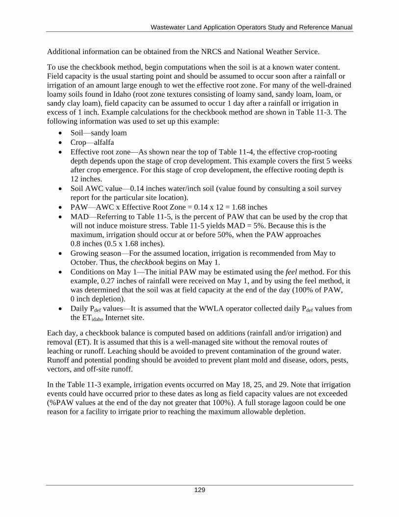
Wastewater Land Application Operators Study and Reference Manual
129
Additional information can be obtained from the NRCS and National Weather Service.
To use the checkbook method, begin computations when the soil is at a known water content.
Field capacity is the usual starting point and should be assumed to occur soon after a rainfall or
irrigation of an amount large enough to wet the effective root zone. For many of the well-drained
loamy soils found in Idaho (root zone textures consisting of loamy sand, sandy loam, loam, or
sandy clay loam), field capacity can be assumed to occur 1 day after a rainfall or irrigation in
excess of 1 inch. Example calculations for the checkbook method are shown in Table 11-3. The
following information was used to set up this example:
Soil—sandy loam
Crop—alfalfa
Effective root zone—As shown near the top of Table 11-4, the effective crop-rooting
depth depends upon the stage of crop development. This example covers the first 5 weeks
after crop emergence. For this stage of crop development, the effective rooting depth is
12 inches.
Soil AWC value—0.14 inches water/inch soil (value found by consulting a soil survey
report for the particular site location).
PAW—AWC x Effective Root Zone = 0.14 x 12 = 1.68 inches
MAD—Referring to Table 11-5, is the percent of PAW that can be used by the crop that
will not induce moisture stress. Table 11-5 yields MAD = 5%. Because this is the
maximum, irrigation should occur at or before 50%, when the PAW approaches
0.8 inches (0.5 x 1.68 inches).
Growing season—For the assumed location, irrigation is recommended from May to
October. Thus, the checkbook begins on May 1.
Conditions on May 1—The initial PAW may be estimated using the feel method. For this
example, 0.27 inches of rainfall were received on May 1, and by using the feel method, it
was determined that the soil was at field capacity at the end of the day (100% of PAW,
0 inch depletion).
Daily Pdef values—It is assumed that the WWLA operator collected daily Pdef values from
the ETidaho Internet site.
Each day, a checkbook balance is computed based on additions (rainfall and/or irrigation) and
removal (ET). It is assumed that this is a well-managed site without the removal routes of
leaching or runoff. Leaching should be avoided to prevent contamination of the ground water.
Runoff and potential ponding should be avoided to prevent plant mold and disease, odors, pests,
vectors, and off-site runoff.
In the Table 11-3 example, irrigation events occurred on May 18, 25, and 29. Note that irrigation
events could have occurred prior to these dates as long as field capacity values are not exceeded
(%PAW values at the end of the day not greater that 100%). A full storage lagoon could be one
reason for a facility to irrigate prior to reaching the maximum allowable depletion.
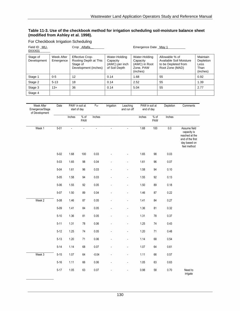
Wastewater Land Application Operators Study and Reference Manual
130
Table 11-3. Use of the checkbook method for irrigation scheduling soil-moisture balance sheet (modified from Ashley et al. 1998).
For Checkbook Irrigation Scheduling
Field ID _MU-0XXX01______
Crop _Alfalfa________ Emergence Date _May 1__________
Stage of Development
Week After Emergence
Effective Crop-Rooting Depth at This Stage of Development (inches)
Water-Holding Capacity (AWC) per inch of Soil Depth
Water-Holding Capacity (AWC) in Root Zone, PAW (inches)
Allowable % of Available Soil Moisture to be Depleted from Root Zone (MAD)
Maintain Depletion Less Than (inches)
Stage 1 0-5 12 0.14 1.68 55 0.92
Stage 2 5-13 18 0.14 2.52 55 1.39
Stage 3 13+ 36 0.14 5.04 55 2.77
Stage 4
Week After Emergence/Stage of Development
Date PAW1 in soil at start of day
Pdef Irrigation Leaching and run off
PAW in soil at end of day
Depletion Comments
Inches % of PAW
Inches inches % of PAW
Inches
Week 1 5-01 - - - - - 1.68 100 0.0 Assume field capacity is
reached at the end of the first day based on feel method
5-02 1.68 100 0.03 - - 1.65 98 0.03
5-03 1.65 98 0.04 - - 1.61 96 0.07
5-04 1.61 96 0.03 - - 1.58 94 0.10
5-05 1.58 94 0.03 - - 1.55 92 0.13
5-06 1.55 92 0.05 - - 1.50 89 0.18
5-07 1.50 89 0.04 - - 1.46 87 0.22
Week 2 5-08 1.46 87 0.05 - - 1.41 84 0.27
5-09 1.41 84 0.05 - - 1.36 81 0.32
5-10 1.36 81 0.05 - - 1.31 78 0.37
5-11 1.31 78 0.06 - - 1.25 74 0.43
5-12 1.25 74 0.05 - - 1.20 71 0.48
5-13 1.20 71 0.06 - - 1.14 68 0.54
5-14 1.14 68 0.07 - - 1.07 64 0.61
Week 3 5-15 1.07 64 -0.04 - - 1.11 66 0.57
5-16 1.11 66 0.06 - - 1.05 63 0.63
5-17 1.05 63 0.07 - - 0.98 58 0.70 Need to irrigate
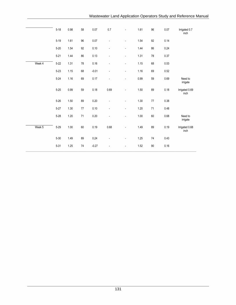
Wastewater Land Application Operators Study and Reference Manual
131
5-18 0.98 58 0.07 0.7 - 1.61 96 0.07 Irrigated 0.7 inch
5-19 1.61 96 0.07 - - 1.54 92 0.14
5-20 1.54 92 0.10 - - 1.44 86 0.24
5-21 1.44 86 0.13 - - 1.31 78 0.37
Week 4 5-22 1.31 78 0.16 - - 1.15 68 0.53
5-23 1.15 68 -0.01 - - 1.16 69 0.52
5-24 1.16 69 0.17 - - 0.99 59 0.69 Need to irrigate
5-25 0.99 59 0.18 0.69 - 1.50 89 0.18 Irrigated 0.69 inch
5-26 1.50 89 0.20 - - 1.30 77 0.38
5-27 1.30 77 0.10 - - 1.20 71 0.48
5-28 1.20 71 0.20 - - 1.00 60 0.68 Need to irrigate
Week 5 5-29 1.00 60 0.19 0.68 - 1.49 89 0.19 Irrigated 0.68 inch
5-30 1.49 89 0.24 - - 1.25 74 0.43
5-31 1.25 74 -0.27 - - 1.52 90 0.16
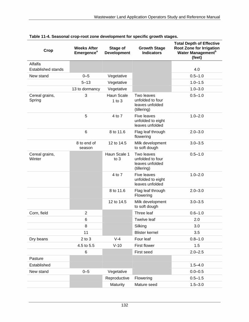
Wastewater Land Application Operators Study and Reference Manual
132
Table 11-4. Seasonal crop-root zone development for specific growth stages.
Crop Weeks After Emergence
a
Stage of Development
Growth Stage Indicators
Total Depth of Effective Root Zone for Irrigation
Water Managementb
(feet)
Alfalfa
Established stands
4.0
New stand 0–5 Vegetative 0.5–1.0
5–13 Vegetative 1.0–1.5
13 to dormancy Vegetative 1.0–3.0
Cereal grains, Spring
3 Haun Scale
1 to 3
Two leaves unfolded to four leaves unfolded (tillering)
0.5–1.0
5 4 to 7 Five leaves unfolded to eight leaves unfolded
1.0–2.0
6 8 to 11.6 Flag leaf through flowering
2.0–3.0
8 to end of season
12 to 14.5 Milk development to soft dough
3.0–3.5
Cereal grains, Winter
Haun Scale 1 to 3
Two leaves unfolded to four leaves unfolded (tillering)
0.5–1.0
4 to 7 Five leaves unfolded to eight leaves unfolded
1.0–2.0
8 to 11.6 Flag leaf through Flowering
2.0–3.0
12 to 14.5 Milk development to soft dough
3.0–3.5
Corn, field 2 Three leaf 0.6–1.0
6 Twelve leaf 2.0
8 Silking 3.0
11 Blister kernel 3.5
Dry beans 2 to 3 V-4 Four leaf 0.8–1.0
4.5 to 5.5 V-10 First flower 1.5
6 First seed 2.0–2.5
Pasture
Established 1.5–4.0
New stand 0–5 Vegetative 0.0–0.5
Reproductive Flowering 0.5–1.5
Maturity Mature seed 1.5–3.0
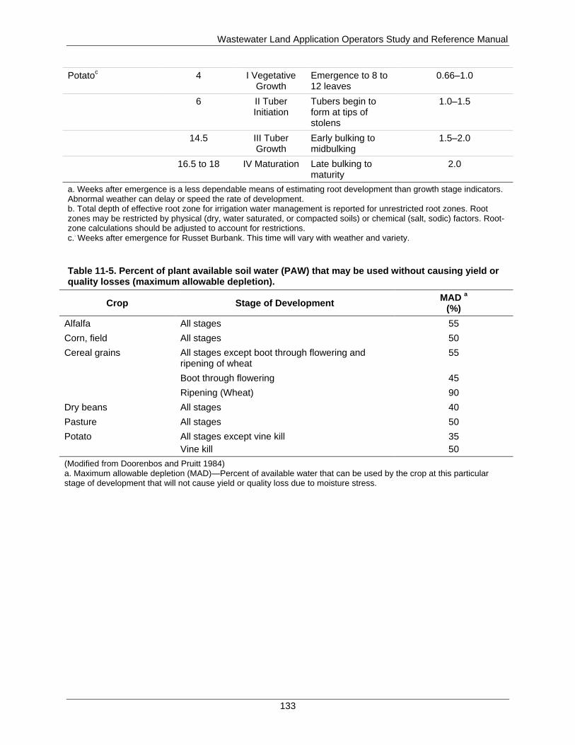
Wastewater Land Application Operators Study and Reference Manual
133
Potatoc 4 I Vegetative
Growth Emergence to 8 to 12 leaves
0.66–1.0
6 II Tuber Initiation
Tubers begin to form at tips of stolens
1.0–1.5
14.5 III Tuber Growth
Early bulking to midbulking
1.5–2.0
16.5 to 18 IV Maturation Late bulking to maturity
2.0
a. Weeks after emergence is a less dependable means of estimating root development than growth stage indicators. Abnormal weather can delay or speed the rate of development. b. Total depth of effective root zone for irrigation water management is reported for unrestricted root zones. Root zones may be restricted by physical (dry, water saturated, or compacted soils) or chemical (salt, sodic) factors. Root-zone calculations should be adjusted to account for restrictions. c.
. Weeks after emergence for Russet Burbank. This time will vary with weather and variety.
Table 11-5. Percent of plant available soil water (PAW) that may be used without causing yield or quality losses (maximum allowable depletion).
Crop Stage of Development MAD
a
(%)
Alfalfa All stages 55
Corn, field All stages 50
Cereal grains All stages except boot through flowering and ripening of wheat
55
Boot through flowering 45
Ripening (Wheat) 90
Dry beans All stages 40
Pasture All stages 50
Potato All stages except vine kill
Vine kill
35
50
(Modified from Doorenbos and Pruitt 1984) a. Maximum allowable depletion (MAD)—Percent of available water that can be used by the crop at this particular stage of development that will not cause yield or quality loss due to moisture stress.
Wastewater Land Application Operators Study and Reference Manual
134
As discussed, soil-water content can be measured or computed by several different methods.
WWLA operators should select the method that is appropriate for their site-specific soils and
crops and one that the WWLA operator feels confident in using.
11.2 Determining How Much to Irrigate
For systems that do not have a land-limiting constituent, the amount of water that can or should
be applied during any single irrigation cycle is dictated by the consumptive needs (hydraulic
needs) of the soil-crop system. For sites with a land-limiting constituent (section 5.4.3),
supplemental irrigation water is typically used to ensure the crop is receiving adequate moisture
for crop health. The appropriate amount to irrigate varies from day to day and from season to
season, as a result irrigation scheduling is influenced by the following:
Pdef (ET – effective rainfall)—When and how much, can be effected by temperature,
wind, and relative humidity
Crop maturity—ET/water uptake rate of the crop
Soil moisture
Effective root depth
Availability of supplemental irrigation water
Recycled water or supplemental irrigation should replace the water that has evaporated from the
soil or been removed by plants. As stated previously, PAW is the AWC of the soil in the root
zone. The existence of bedrock, gravels, and hardpan layers can limit the maximum effective
rooting depths to as little as 12 to 18 inches. It is within this depth that we estimate or measure
the PAW deficit to be replaced by irrigation and/or precipitation.
Therefore, irrigation should be scheduled and timed so that the following applies:
No surface ponding or runoff occurs during irrigation
The root zone is not completely saturated at the conclusion of irrigation
The irrigated water does not leach below the root zone
If the soil is at the permanent wilting point, the PAW deficit would be the entire PAW value for
the given soil type (values shown in Table 11-1). In reality, the WWLA operator should never
allow the soil to reach the permanent wilting point. Typically, the amount of soil water to be
replaced will be less than the MAD (around 50% PAW) to avoid inducing moisture stress
resulting in reduced yields. For example, Table 11-2 recommends water irrigation volumes based
on estimates of PAW using the feel method.
Another factor affecting irrigation amount is the soil infiltration rate. As discussed in section
6.4.2, the infiltration rate is the maximum rate at which water enters the soil, typically expressed
in inches per hour. PAW depletion and the soil infiltration rate are factors determining the
amount of water that can be applied at the land application site at any given time. Infiltration rate
is a function of the following:
Soil texture
Soil structure
Soil moisture
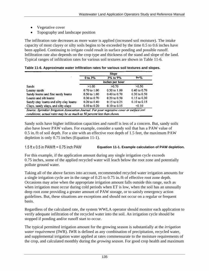
Wastewater Land Application Operators Study and Reference Manual
135
Vegetative cover
Topography and landscape position
The infiltration rate decreases as more water is applied (increased soil moisture). The intake
capacity of most clayey or silty soils begins to be exceeded by the time 0.5 to 0.6 inches have
been applied. Continuing to irrigate could result in surface ponding and possible runoff.
Infiltration rate also depends on the crop type and thickness of the stand and slope of the land.
Typical ranges of infiltration rates for various soil textures are shown in Table 11-6.
Table 11-6. Approximate water infiltration rates for various soil textures and slopes.
Sandy soils have higher infiltration capacities and runoff is less of a concern. But, sandy soils
also have lower PAW values. For example, consider a sandy soil that has a PAW value of
0.5 in./ft of soil depth. For a site with an effective root depth of 1.5 feet, the maximum PAW
depletion is only 0.75 inches (Equation 11-1).
1.5 ft x 0.5 in PAW/ft = 0.75 inch PAW Equation 11-1. Example calculation of PAW depletion.
For this example, if the application amount during any single irrigation cycle exceeds
0.75 inches, some of the applied recycled water will leach below the root zone and potentially
pollute ground water.
Taking all of the above factors into account, recommended recycled water irrigation amounts for
a single irrigation cycle are in the range of 0.25 to 0.75 in./ft of effective root zone depth.
Occasions may arise when the appropriate irrigation amount falls outside this range, such as
when irrigation must occur during cold periods when ET is low, when the soil has an unusually
deep root zone providing a greater amount of PAW storage, or to satisfy emergency action
guidelines. But, these situations are exceptions and should not occur on a regular or frequent
basis.
Regardless of the calculated rate, the system WWLA operator should monitor each application to
verify adequate infiltration of the recycled water into the soil. An irrigation cycle should be
stopped if ponding and/or runoff start to occur.
The typical permitted irrigation amount for the growing season is substantially at the irrigation
water requirement (IWR). IWR is defined as any combination of precipitation, recycled water,
and supplemental irrigation water applied at rates commensurate to the moisture requirements of
the crop, and calculated monthly during the growing season. For good crop health and maximum
Wastewater Land Application Operators Study and Reference Manual
136
yields, the WWLA operator should schedule irrigations so that the hydraulic-loading rate is as
close to the IWR as possible. If the actual hydraulic-loading rate is below the IWR, crop health
and yield will be reduced. In addition, irrigation at the IWR may not be feasible on soils with a
high leaching potential. Overall supplemental irrigation may be used when the recycled water
application does not satisfy the IWR.
Equation 11-2 is used to calculate the IWR:
IWR = Pdef / Ei Equation 11-2. Calculation of irrigation water requirement.
where:
Pdef is the precipitation deficit. Pdef is equal to the consumptive use of the crop minus the
effective precipitation and is synonymous with the net irrigation requirement (IRnet). Values
for Pdef can be found for various locations around the state at the ET Idaho website :
http://data.kimberly.uidaho.edu/ETIdaho/.
Ei is the irrigation system efficiency.
For permit purposes, the soil carry over moisture and leaching rate are assumed to be zero and,
therefore, are not considered when calculating the IWR.
11.2.1 Operational Considerations
A key component of the irrigation design is to select the proper combination of system
components so that the system irrigation rate does not exceed the infiltration rate of the soil.
Knowledge of the system design is important for day-to-day irrigation scheduling.
Several terms may be used to express the rate at which water is being applied to a field during
irrigation, including discharge rate and irrigation rate:
Discharge rate (flow rate) is the volume of water exiting a sprinkler per unit of time. Discharge
rates are normally expressed in terms of gallons per minute (gpm). Manufacturers publish
discharge rates for their sprinklers as a function of operating pressure and orifice diameter of the
nozzle. Keep a copy of the manufacturer’s discharge specifications for the sprinklers on your
system. Discharge characteristics for three typical sprinklers used for wastewater irrigation are
given in Table 11-7. For example, a Rainbird Model 70 sprinkler operated at 55 psi with a 9/32-
inch diameter nozzle has a discharge rate of 17.2 gpm. Discharge characteristics for typical big
guns are shown in Table 11-8. For contrast, notice how much higher discharge rates are for the
gun sprinklers than for the rotary impact sprinklers.
In general, a larger nozzle with the same pressure creates an increased discharge rate, and a
smaller nozzle with the same pressure creates a decreased discharge rate.
Additionally, changing pressures within sprinkler systems impact the wetted area, so increasing
pressures increase the wetted diameter. Conversely decreasing pressures decrease the wetted
diameter.
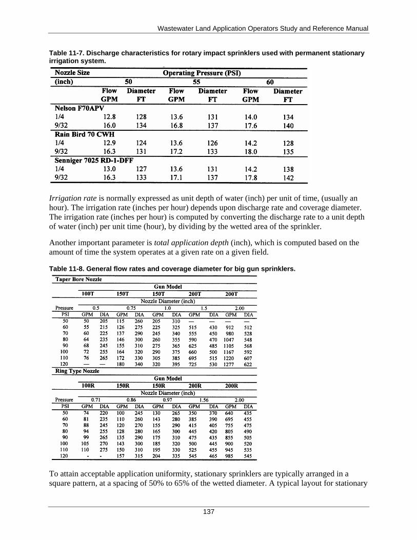
Wastewater Land Application Operators Study and Reference Manual
137
Table 11-7. Discharge characteristics for rotary impact sprinklers used with permanent stationary irrigation system.
Irrigation rate is normally expressed as unit depth of water (inch) per unit of time, (usually an
hour). The irrigation rate (inches per hour) depends upon discharge rate and coverage diameter.
The irrigation rate (inches per hour) is computed by converting the discharge rate to a unit depth
of water (inch) per unit time (hour), by dividing by the wetted area of the sprinkler.
Another important parameter is total application depth (inch), which is computed based on the
amount of time the system operates at a given rate on a given field.
Table 11-8. General flow rates and coverage diameter for big gun sprinklers.
To attain acceptable application uniformity, stationary sprinklers are typically arranged in a
square pattern, at a spacing of 50% to 65% of the wetted diameter. A typical layout for stationary
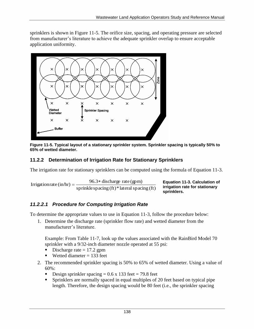
Wastewater Land Application Operators Study and Reference Manual
138
sprinklers is shown in Figure 11-5. The orifice size, spacing, and operating pressure are selected
from manufacturer’s literature to achieve the adequate sprinkler overlap to ensure acceptable
application uniformity.
Figure 11-5. Typical layout of a stationary sprinkler system. Sprinkler spacing is typically 50% to 65% of wetted diameter.
11.2.2 Determination of Irrigation Rate for Stationary Sprinklers
The irrigation rate for stationary sprinklers can be computed using the formula of Equation 11-3.
(ft) spacing lateral*(ft) spacing sprinkle
(gpm) rate discharge 96.3(in/hr) rateIrrigation
Equation 11-3. Calculation of
irrigation rate for stationary sprinklers.
11.2.2.1 Procedure for Computing Irrigation Rate
To determine the appropriate values to use in Equation 11-3, follow the procedure below:
1. Determine the discharge rate (sprinkler flow rate) and wetted diameter from the
manufacturer’s literature.
Example: From Table 11-7, look up the values associated with the RainBird Model 70
sprinkler with a 9/32-inch diameter nozzle operated at 55 psi:
Discharge rate = 17.2 gpm
Wetted diameter = 133 feet
2. The recommended sprinkler spacing is 50% to 65% of wetted diameter. Using a value of
60%:
Design sprinkler spacing = 0.6 x 133 feet = 79.8 feet
Sprinklers are normally spaced in equal multiples of 20 feet based on typical pipe
length. Therefore, the design spacing would be 80 feet (i.e., the sprinkler spacing
Wastewater Land Application Operators Study and Reference Manual
139
along the lateral would be 80 feet, and the lateral spacing would be 80 feet, so that the
effective area of a sprinkler would be 80 x 80 feet).
3. The irrigation rate is then computed:
in/hr 0.26ft 80 * ft 80
gpm 17.2 * 96.3 (in/hr) rate Irrigation
The irrigation rate of the sprinkler should be less than the infiltration rate of the soil, as
given in Table 11-6.
4. Application depth is then computed as the irrigation rate multiplied by the operating time.
In most cases, select the desired application depth based on one of the above methods.
Compute the time required to operate the system to achieve the desired application depth.
For example, if the required application depth is 0.6 inches, then the selected operating
time for the system would be computed as follows:
(in/hr) rate irrigation
(in) depth napplicatio target (hours) Operation of Time
So,
hours 2.3in/hr 0.26
in 0.6 (hours) Operation of Time
11.2.3 Center Pivot Systems
Center pivot systems come in a variety of designs and with many operational considerations. The
newer models use a controller device that allows the WWLA operator to set and vary irrigation
rates based on field variability or crop types over which the system is run. Since these systems
can cover a large area, the sprinkler components are typically designed and installed for each
individual situation. Therefore, no standard formula can determine the irrigation rate or travel
speed for these systems. The manufacturer’s literature will explain the settings to achieve desired
irrigation rates and volumes. Like any other type of irrigation equipment, it should be field
calibrated periodically to verify that field irrigation rates are consistent with manufacturer’s
design.
11.3 Equipment Calibration and Application Uniformity
Irrigation equipment must be calibrated based upon manufacturer’s recommendations and site
conditions. Irrigation systems determine hydraulic and nutrient loading to the site so application
uniformity is important. Application uniformity “describes how evenly an application system
distributes water over a field”(James 1988).
Manufacturer’s specifications on irrigation equipment is usually based upon average operating
conditions with relatively new equipment on flat ground with no wind. Discharge rates and
irrigation rates change over time as equipment gets older and components wear. In particular,
pump wear tends to reduce operating pressure and flow. With continued use, nozzle wear results
in an increase in the nozzle opening.
Wastewater Land Application Operators Study and Reference Manual
140
When the nozzle opening changes (e.g., wear) from the original design, if nothing else changes,
the discharge rate will increase and the pressure will decrease, which also decreases the wetted
diameter. If system adjustments are made so that the pressure stays constant, then the increased
opening will increase the flow and wetted diameter.
Be aware that operating the system differently than assumed in the design will alter the irrigation
rate, coverage diameter, and subsequently the application uniformity. For example, operating the
system with increased pressure, results in smaller droplets. The smaller droplets have greater
potential for drift and odor. Additionally increased pressure increases the nozzle wear.
Clogged nozzles can result in pressure increase. Plugged intakes or crystallization of mainlines
will reduce operating pressure. Operating below design pressure greatly reduces the coverage
diameter and application uniformity.
Field calibrate the equipment on a regular basis to ensure proper irrigation rates and application
uniformity. Field calibration for uniformity is recommended at least once every 3 years.
Calibration involves collecting and measuring flow at several locations in the irrigation area.
Any number of containers can be used to collect flow and determine the irrigation rate. Rain
gauges work best because they already have a graduated scale from which to read the irrigation
amount without having to perform additional calculations. However, pans, plastic buckets, jars,
or anything with a uniform opening and cross section can be used if the liquid collected can be
easily transferred to a scaled container for measuring.
For stationary sprinklers, collection containers should be located in a grid pattern throughout the
irrigation area at several distances from sprinklers. Collection gauges should be spaced one-
quarter the effective sprinkler spacing apart. For traveling guns, sprinklers should be located
along a transect perpendicular to the direction of pull. Set out collection containers no further
than 25 feet apart along the transect on both sides of the gun cart.
WWLA operators should compute the average irrigation rate for all collection containers and
have the irrigation (or application) uniformity coefficient calculated for the system. The
calculation of the uniformity coefficient is based on a complex calculation called the
Christiansen calculation and is beyond the scope of this manual (procedures for calculating the
uniformity coefficient can be found in the American Society of Agricultural Engineers standards
(ASAE 1999). Ideally 100% uniformity is desirable but not practical, and typical values of
uniformity range from 70% to 95%. A uniformity of less than 70% usually indicates system
maintenance problems that need to be resolved. The WWLA operator can use the flow into each
of the containers, described above, to determine how evenly the sprinkler system applies the
water across the field. A deviation (more or less) from the average flow collected will tell the
WWLA operator if a portion of the field is being underirrigated or overirrigated, which in either
case will affect crop yield. Having a higher application uniformity will mean higher yields and a
more profitable land application site.
Some of the maintenance problems that can contribute to low application uniformity are worn or
plugged irrigation nozzles (measure for wear), a too high or too low system pressure, irregular
rotation of the irrigation head, a sprinkler axis of rotation that is not vertical, and system leaks.
Wastewater Land Application Operators Study and Reference Manual
141
11.3.1 Summary of Irrigation Scheduling
This section has introduced a number of soil-water terms and irrigation formulas used to help
determine how to properly apply wastewater. The use of these terms and formulas requires
knowing the following items about the system and land application site:
Soil types and infiltration rates by field
Weekly, monthly, and annual irrigation depths
Soil-water relationships and properties
Acreage of each field to receive recycled water applications
Application equipment types and specifications include the following:
Operating pressure
Nozzle diameter
Flow or delivery rate in gallons per minute per sprinkler
Diameter of throw of sprinkler
Travel speed settings for traveling equipment
Number of sprinklers
With this information, WWLA operators can perform the calculations to properly develop an
irrigation schedule for the land application system. With proper operation and maintenance,
recycled water and any supplemental irrigation water may be applied to meet the moisture
requirements of the soil-crop system while protecting the quality of the land application
environment.

Wastewater Land Application Operators Study and Reference Manual
142
This page intentionally left blank for correct double-sided printing.
Wastewater Land Application Operators Study and Reference Manual
143
12 Sampling
Need-to-Know Criteria
Sampling requirements, importance, number, and frequencies
Soil sampling
Plant tissue sampling
Ground water sampling
Minimizing contamination risks
Procedures for packing and shipping ground water samples
Sampling is important for proper operation of a land application site because the sample results
tell the WWLA operator if the site is being managed properly and allows the WWLA operator to
make informed decisions to avoid any possible adverse impacts to ground water, surface water,
or public health. Most reuse permits require soil, plant tissue, recycled water, supplemental
irrigation water, and ground water sampling and analyses. If such monitoring is required, the
reuse permit will specify which parameters to monitor, when and how often to monitor, number
of samples to be taken, and when results must be submitted. Although such sampling may not be
required by every permit, all WWLA operators should have a basic understanding of the
different types of analyses available, proper sampling techniques, and how to interpret analysis
results.
12.1 Soil Sampling
The permit governs specific site sampling. Sampling procedures should be developed for each
site and are usually found in the site facility QAPP. Each procedure should include information
to ensure consistency from one sampling event to another, communication with the laboratory
for proper methods, chain-of-custody procedures, and data handling for reporting purposes.
Proper collection of samples and maintenance of sample analysis records is required by the
permit. Additionally, the data from these samples should provide information to assist with
efficient site operation and maintenance.
Soil sampling procedures should be in your QAPP, so follow your site QAPP. It is not possible
to look at a soil and predict if it is too acidic or if there are proper amounts of the essential
nutrients present. Soils in Idaho vary in their need for nutrients, depending on soil characteristics,
previous fertilization levels, and nutrient requirements of the crop.
The goal of soil testing is to learn enough about the soil to provide economically and
environmentally sound nutrient recommendations and to help evaluate the operation and
management of the land application site. Soil testing provides an approach for WWLA operators
to assess soil pH and plant-available nutrients, to determine the need for chemicals and
fertilizers, and to avoid losses and environmental damage from improper practices.
Wastewater Land Application Operators Study and Reference Manual
144
The University of Idaho Cooperative Extension System Bulletin 704 on Soil Sampling provides
information about collecting soil samples (Appendix F). For information on how to analyze soil
samples, consult with the soil testing laboratory that will conduct the soil testing.
12.1.1 Soil Test
A soil test analysis is a chemical evaluation of the nutrient availability of the soil at the time of
sampling. This is the nutrient supply available but is not a measurement of the plant-available
nutrients because, as discussed in section 5, not all nutrients in the soil are in a form readily
usable by plants. A goal of testing is to establish if there is nutrient overloading, enough
nutrients, or nutrient deficiency. In deficient soils, nutrients needed for crops can be added as
fertilizer.
Different methods may be used to sample soil, and understanding the reliability of each method
is important.
12.1.2 Sampling Timing
Soils change through the seasons as water passing through the soils changes the nutrient contents
available for crop uptake. Therefore, the timing of soil sampling should be close to planting
and/or fertilization (recommended 2 to 4 weeks prior to fertilization or planting crops). Check
with the laboratory well ahead of time for any special sample requirements including quantity,
container types, turnaround time and specific analysis to be done. The reuse permit will establish
the sampling minimum requirements for time and frequency.
12.1.3 Sampling Procedure
The permit governs specific site sampling. The site QAPP should incorporate the permit
sampling requirements. The QAPP should consider that soil samples must be taken following a
procedure that yields representative sampling of the site. The samples should be taken from
representative areas, not from unusual areas such as fence lines or rock outcroppings. Generally,
sampling equipment should be identified and constructed of materials that will not contaminate
or react with the soils. Equipment should be clean and free of fertilizer and not made of
galvanized iron or zinc coated. Fertilizer can create inaccurate results in the soil analysis. Test
equipment made of galvanized iron or zinc could add zinc or iron into the sample. Depth of each
sample must also be accounted for as nutrient levels in soil may be different in the different soil
zones. The reuse permit will also establish the nutrients that must be sampled for and the depths
of sampling.
Test methods should indicate a certain number of grab samples composted into a representative
sample that is matched with the depth of the soil sample collected with the crop, tillage depth,
and nutrients to be analyzed. The number of subsamples that should be taken to make a
composite soil sample will be stated in the facility permit.
12.1.4 Using a Soil Test to Determine the Land-Limiting Nutrient
In situations where land application is limited by nutrients rather than by hydraulics, soil tests
can be used to help determine the land-limiting nutrient. The land-limiting nutrient is the nutrient
most likely to cause an adverse environmental or plant health effect if more is applied than the
Wastewater Land Application Operators Study and Reference Manual
145
plants can use. Generally, nitrogen is the most common land-limiting nutrient, and application
rates are based on supplying crop nitrogen (N) needs. The idea is to not apply nitrogen at rates
greater than the crop can use because the nitrate form of nitrogen can move through the soil and
threaten ground water quality.
12.2 Plant Tissue Sampling
The permit governs specific site sampling. The site QAPP should incorporate the permit
sampling requirements. The QAPP should consider that plant samples must be taken following a
procedure that yields representative as harvested samples. Healthy plants contain predictable
concentrations of the essential elements. If these elements are not present in adequate amounts,
then the plant suffers from a nutrient deficiency. In some cases, these nutrients are present in
higher concentrations than required, and the plant may suffer from a nutrient toxicity. In either
case, the plant is not healthy and is not efficiently removing nutrients from the soil. Plant tissue
sampling can be used to distinguish between nutrient deficiency, nutrient sufficiency, and
nutrient toxicity, which is an indication of crop health during the growing season (crop
management). However, crop uptake determines nutrient removal from the land application site
during harvest and is a permit requirement. Plant tissue sampling may be different depending on
whether the information needed is to determine proper crop management for crop health or
whether the information is needed to determine harvested crop uptake for permit compliance.
A recent soil test result can be helpful when interpreting plant tissue analysis. When visual
symptoms of a suspected nutrient deficiency are present, take a soil sample at the same time
from root zones of plants sampled. In this way, an evaluation of the soil in the affected area can
be made along with an evaluation of the plant tissue. Sampling healthy and unhealthy plants, and
their respective soil, is an effective crop management tool in determining optimum additions of
plant nutrients to the soil (such as supplemental fertilizer). Taking some soil samples can help
determine true harvested crop uptake for nitrogen in legumes, such as alfalfa, which has the
ability to fix nitrogen from the atmosphere.
Plant analysis results can do the following:
Indicate the nutritional status of plants (both crop management and crop uptake)
Identify deficiencies and toxicities (crop management)
Provide an accounting of nutrient utilization (crop uptake)
Provide a mechanism for optimizing yield, quality, and efficiency (both crop
management and crop uptake)
Plant analysis assesses nutrient uptake while soil testing predicts nutrient availability. The two
tests are complementary as crop management tools, but each has limitations. Soil testing is not
always a good indicator of nutrients such as nitrogen and sulfur that leach easily.
For crop management, a plant analysis may indicate that a nutrient deficiency or toxicity does
not exist. Therefore, a factor other than nutrition may be responsible for poor plant growth or
visual symptoms.
For crop uptake and permit compliance, plant tissue sampling is used to determine the amount of
nutrients removed by the land application system. A sample of the harvested crop tissue is
Wastewater Land Application Operators Study and Reference Manual
146
analyzed for nitrogen and phosphorus content to determine the amount removed from the field.
Testing for ash may also be specified; ash results can be used to estimate the amount of TDS
removed from the field.
If plant tissue monitoring is required by your system permit, the permit will specify which
parameters to monitor, when to monitor, and when results must be submitted. However,
additional sampling outside the permit may be needed for crop management analysis to
determine crop health.
In the following subsections on plant tissue sampling, each subsection is divided into crop
management or crop uptake to help the WWLA operator determine the type of sampling needed
for each.
12.2.1 Taking a Representative Sample
Proper sampling is the key to reliable plant analysis results and required by permit. Sampling
instructions, information sheets, and shipping envelopes are provided at no charge and can be
obtained at the local Cooperative Extension Service.
When used for crop management, take samples from both good and bad areas. Comparison
between the groups of samples helps pinpoint the limiting element. Comparative sampling also
helps factor out the influence of drought stress, disease, or injury. Take matching soil samples
from the root zones of both good and bad plants for the most complete evaluation.
When monitoring the status of healthy plants, take samples from a uniform area. If the entire
field is uniform, one sample can represent a number of acres. If there are variations in soil type,
topography, or crop history, take multiple samples so that each management area is represented
by its own sample.
When monitoring for crop uptake of nutrients, take a sample that represents each harvested crop
during each crop harvest/cutting. A representative sample is a composite sample of only the plant
parts that are removed from the site. For alfalfa, a representative sample would be a composite
sample of the entire harvested plant for each management unit. See Appendix G for more
information on crop tissue sampling for crop uptake determination. Contact the analyzing lab for
the appropriate sample size of crop tissue sampling for crop uptake determination.
12.2.2 Selecting the Best Indicator Sample for Crop Management
The appropriate part of the plant to sample varies with crop, stage of growth, and purpose of
sampling. For mature plants, the most recent mature leaf (MRML) is the best indicator sample,
except as noted in Table 12-1.
The MRML is the first fully expanded leaf below the growing point. It is neither dull from age
nor shiny green from immaturity. For some crops, the MRML is a compound leaf.
Wastewater Land Application Operators Study and Reference Manual
147
Table 12-1. Situations in which the most recent mature leaf is not the best indicator sample.
Alfalfa, clover Early growth through maturity—take top 2 to 3 inches of the plant
Corn Bloom through maturity—take ear leaf
Small grain Bloom through maturity—take the flag leaf
Turfgrass Take clippings from mower bag
12.2.3 Choosing Sample Size for Crop Management
Laboratory analysis requires less than 1 gram of tissue, but a good sample contains enough
leaves to represent a composite of the crop being managed. Therefore, the larger the area is, the
larger the sample size needs to be.
Sample size also varies with crop. For crops with large leaves, a sample of three or four leaves is
adequate. For crops with small leaves, a sample of 25 to 30 leaves is more appropriate. For most
crops, 8 to 15 leaves is adequate.
12.2.4 Submitting the Sample
The following should be considered during sampling:
1. Use permanent ink or pencil on sample forms and envelopes. Tissue sample envelopes
and information sheets are available from local Cooperative Extension Service.
2. Pay attention to detail when filling out the information sheet. Supply the information
requested. Note any conditions—drought, disease, injury, pesticide, or foliar nutrient
applications—that might be relevant.
3. When identifying the plants sampled, give the exact name, if possible. Give each sample
a unique identifier that will help identify the plants or area to which it corresponds.
4. When sending matching soil, solution, or waste samples, indicate the matching sample
identification on the forms. Be sure the grower’s name and address are exactly the same
on all matching information sheets.
5. Ship all matching samples in the same container.
6. Ship the tissue sample in a paper envelope or cardboard box, so it can begin drying
during transport. Samples put in plastic bags will rot, and decomposition may alter test
results.
12.3 Recycled Water Sampling
The permit governs specific site sampling. The site QAPP should incorporate the permit
sampling requirements. Recycled water analysis is an efficient way to measure the levels of
nutrients and other constituents in the land-applied water. Because the amounts of these
constituents can vary among recycled water streams, laboratory analysis lets the WWLA
operator know the proper amount of water to apply to meet the specific plant and general
management needs for each site.
When management decisions are made without a water analysis information, even well-
intentioned users can reduce plant growth and yields or endanger the environment. Typically,
monthly sampling and analysis of the land-applied water is required in the reuse permit. The
Wastewater Land Application Operators Study and Reference Manual
148
sample collection location and constituents to be analyzed are specified in the permit and vary
between facilities, depending upon site characteristics and management practices.
WWLA operators who fail to test recycled water are faced with a number of questions they
simply cannot answer:
Are they supplying plants with adequate nutrients?
Are they building up excess nutrients that may ultimately move to streams or ground
water?
Are they changing the soil pH to levels that will not support plant production?
Are they applying heavy metals at levels that may be toxic to plants and permanently
alter soil productivity?
Because environmental damage and losses in plant yield and quality often happen before visible
plant symptoms, WWLA operators should always have the recycled water analyzed by a
competent laboratory, and they are encouraged to have the application rates evaluated by a
knowledgeable agronomist.
12.3.1 Recycled Water Sampling Terminology
The WWLA operator should be familiar with the following sampling terms:
Grab sample—Collected over a period not exceeding 15 minutes. A grab sample is
normally associated with water or wastewater sampling. However, soil and sediment may
also be considered grab samples; no particular time limit would apply for the collection
of such samples. Grab samples are used to characterize the medium at a particular instant
in time and are always associated with instantaneous flow data, where appropriate. Grab
sampling is conducted when the following is true:
The recycled water stream is not continuous.
The characteristics of the recycled water stream are known to be of consistent quality.
The sample is to be analyzed for parameters whose characteristics are likely to
change significantly with time (e.g., dissolved gases and bacteria).
The sample is to be collected for analysis of a parameter where the compositing
process could significantly affect the observed concentrations.
Data on maximum/minimum concentrations are desired for a continuous recycled
water stream.
When the permit monitoring requirements specify grab sample collection.
Composite sample—Used when average concentrations are of interest and are always
associated with average flow data (where appropriate). Composite sampling is employed
when the recycled water stream is continuous or it is necessary to calculate mass/unit
time loadings or when analytical capabilities are limited. Many reuse permits require
composite sampling of the land-applied water.
Split sample—Portioned into two or more containers from a single container. Portioning
assumes adequate mixing to ensure the split samples are, for all practical purposes,
identical.
Duplicate sample—Collected simultaneously from the same source, under identical
conditions, and into separate containers.
Wastewater Land Application Operators Study and Reference Manual
149
Control sample—Collected upstream or upgradient from a source or site to isolate the
effects of the source or site on the particular medium being evaluated.
Background sample—Collected from an area, water body, or site similar to the one being
studied but located in an area known or thought to be free from effects resulting from
reuse system operations. For example upgradient well water not impacted the site.
Sample aliquot—Portion of a sample that is representative of the entire sample.
12.3.2 Sampling Procedures
Proper sampling is the key to reliable analysis results through a written procedure that was
followed and documented. Although laboratory procedures can be extremely accurate, they have
little value if the samples fail to represent actual conditions. The importance of careful sampling
becomes clear when one recognizes that laboratory determinations are often made on a portion of
the sample submitted that is as little as 0.02 pound, (1 gram) for solid materials, or less than a
tablespoon (10 milliliters [mL]) for liquid materials.
Important considerations for obtaining representative recycled water samples may include the
following:
Sample locations taken from pipelines should be located where the stream will be well-
mixed (turbulent conditions).
For open flow channels, samples should be collected near the center of the flow channel,
at a depth of approximately half the total depth, where the turbulence is at a maximum
and the possibility of solids settling is minimized. Skimming the water surface or
dragging the bottom should be avoided.
When sampling from a mixing zone, cross-sectional sampling should be considered. Dye
may be used as an aid in determining the most representative sampling points.
For lagoons, the sampling method will depend on if the lagoon is well mixed or
quiescent. For quiescent lagoons, it may require sampling at multiple depths and
compositing to get a representative sample.
Determine if the sample has special container requirements, temperature requirements
and/or requires preservatives and make arrangements to have these items covered prior to
going out in the field to obtain samples.
Verify and collect the minimum amount of sample volume required by the laboratory.
12.4 Ground Water Sampling
Ground water monitoring is a standard requirement of most reuse permits to ensure that
deterioration of ground water quality does not occur. One of the most critical parts of ground
water monitoring is the sample collection process, which is discussed in the site QAPP. The
permit site sampling requirements should be incorporated within the QAPP. Laboratories cannot
compensate for a contaminated sample, and the sampling method is crucial for establishing
permit compliance.
Wastewater Land Application Operators Study and Reference Manual
150
Note
For additional guidance on ground water well monitoring see the Guidance for Reclamation and Reuse of Municipal and Industrial Wastewater (DEQ guidance) at www.deq.idaho.gov/media/516329-guidance_reuse_0907.pdf.
The following discussion concentrates on the most common ground water monitoring procedures
for land application systems. It is beyond the scope of this manual to cover all of the types of
monitoring systems and wells. However, no matter what type of well is being sampled, the
procedures and important concepts covered should be followed consistently throughout the
monitoring process.
If monitoring wells are required, a state-licensed engineer or hydrogeologist must prepare a
report describing the depth of the ground water (“Well Construction Standards Rules” [IDAPA
37.03.09]) and must collect samples to establish background levels for the parameters of interest.
This is usually done when the well has been drilled. As with other types of monitoring, the
system’s permit will specify what parameters to monitor, when to monitor, and when results
must be submitted.
When reporting ground water monitoring data, describe the well location and use the monitoring
serial numbers designated in the permit. In addition, identify each well as upgradient or
downgradient in relation to the wastewater land application site. Upgradient wells are used for
taking background water quality samples to determine the extent of ground water contamination
by the land application site.
Information concerning proper ground water monitoring well location and construction is
presented in section 7.5. Ground water sampling techniques are covered in this section and
maintenance for monitoring well protection is described in section 13.4.
Ground water is sampled from specially designed wells that are carefully located. The wells must
be sampled immediately after construction and then, if possible before land application begins—
this determines background levels of constituents that are to be monitored. The system permit
gives the frequency for all sampling based on facility and site conditions.
Before beginning compliance monitoring, complete the following:
Determine the sampling schedule and parameters to be monitored as specified in the
permit.
Have a QAPP that covers ground water monitoring requirements.
Select a laboratory that can meet the permit requirements.
Provide the laboratory with a copy of the QAPP and monitoring requirements in the
permit.
Prior planning and careful preparation of field equipment before sampling will ensure good
results from the laboratory. Appendix H is a list of supplies and equipment to be used when
sampling ground water.
Wastewater Land Application Operators Study and Reference Manual
151
12.4.1 Minimizing Contamination Risks
Minimize contamination risks while collecting samples:
Ensure that all sampling equipment (e.g., bailers, tubing, and containers) has been
thoroughly cleaned and selected based on compatibility with parameters to be monitored.
Use Teflon, stainless steel, or glass when sampling for organics; do not use PVC or other
plastics.
Use Teflon or glass when sampling for trace metals.
Use new sample containers when sampling for compliance monitoring; do not reuse
containers.
Keep containers closed before filling, and do not touch the inside of containers or caps.
Wear a new pair of disposable gloves or decontaminated reusable gloves for each
sampling site.
Place new plastic sheeting on the ground near each well to hold the sampling equipment;
do not step on the sheeting.
Place small samples that require cooling, such as volatile organics, in sealable containers
immediately after collection and before submerging in ice.
Do not smoke while collecting or handling samples, because volatile residues in the
smoke can cause sample contamination.
Do not leave your vehicle running near the sample collection area to prevent
contamination from engine exhaust fumes.
If an internal combustion generator is used, set up the generator at least 15 feet away and
downwind from the well; perform all generator maintenance and fueling off-site and
away from samples.
Avoid unnecessary handling of samples.
If dedicated monitoring systems (those permanently installed in wells) are not used, clean
equipment to be reused thoroughly before sampling each well to minimize the risk of
cross contamination; bailers left in wells are not dedicated systems.
Take enough precleaned equipment to the field to sample each well, so that cleaning
between wells is unnecessary; if field cleaning is necessary, an equipment blank may be
used to ensure that no contamination results.
Blanks should be used to check for contamination. Blanks consist of organic-free deionized
water, which must be obtained from laboratories. Types of blanks include the following:
A trip blank is a sealed container of organic-free, deionized water that must be taken to
the field and sent back to the laboratory, unopened, with the samples; include at least one
trip blank per cooler for volatiles to check for sample contamination during
transportation.
A field blank consists of organic-free deionized water taken to the field and handled in
the same manner as the samples to check for contamination from handling, from added
preservatives, or from airborne contaminants at the site, which are not from the waste
being disposed of at the treatment facility.
An equipment blank is organic-free deionized water, which is passed through the cleaned
sampling equipment with added preservatives and is used to detect any contamination
from equipment used for more than one well

Wastewater Land Application Operators Study and Reference Manual
152
12.4.2 Purging the Well
Before collecting any ground water samples, adequately remove stagnant water from the well by
doing the following:
1. To purge a sufficient amount of water from a well, first calculate the well volume.
2. Based on the calculated well volume, pump or bail at least three well volumes from the
well and/or until measurements for pH, specific conductance, and temperature meet the
following conditions:
Two successive temperature values measured at least 5 minutes apart are within 1 °C
of each other.
pH values for two successive measurements, measured at least 5 minutes apart, are
within 0.2 units of each other.
Two successive specific conductance values, measured at least 5 minutes apart, are
within 10% of each other.
This procedure will determine when the well is suitable for sampling for constituents required by
the permit. Other procedures, such as low flow sampling, may be considered by DEQ for
approval.
Following well recovery, samples may be collected using low rate pumping devices or a bailer.
Dispose of purged water appropriately, according to state and federal regulations.
12.4.2.1 Purging with a Pump
Low rate pumping is the preferred method for purging because bailing may increase turbidity by
stirring up sediment in the well. When purging with a pump, do the following:
Slowly lower the pump to just below the top of the standing water column.
Continue lowering it as the water level drops and the stagnant water is removed, as
explained in section 12.4.2.
12.4.2.2 Purging with a Bailer
Using low flow pumps for purging generally produces high quality representative samples.
However, if a pump is not available or cannot be used, use a bottom-emptying bailer to purge
and collect samples. Bailer lines of braided nylon or cotton cord must not be reused, even if
clean, to avoid the probability of cross contamination. Lines must consist of Teflon-coated wire,
single-strand stainless steel wire, or other monofilament line.
Note
Do not leave bailers in wells. Contamination can occur when they are handled outside the wells and placed back inside. Contamination can also occur as a result of deterioration of bailer lines.
To purge using a bailer, do the following:
Lower the bailer slowly, to just below the water level, and retract slowly to reduce
aeration and turbidity.
Collect the purged water in a graduated bucket to measure a minimum of at least three
well volumes, or as discussed in section 12.4.2.
Wastewater Land Application Operators Study and Reference Manual
153
12.4.2.3 Collecting Samples
After wells are purged, collect samples using a low rate pump or a bottom-emptying bailer.
Sample containers obtained from commercial laboratories or laboratory suppliers may already
contain the appropriate preservatives. Check with the laboratory and follow their instructions.
12.4.2.4 Sampling with a Portable Pump
When sampling with a portable pump, do the following:
1. Lower the pump, slowly, to the desired depth in the well. (Have sample containers ready
before turning on the pump.)
2. Adjust the flow rate to reduce agitation (generally this is less than 100 mL per minute).
3. Decontaminate the pump before moving to the next well.
12.4.2.5 Sampling with a Bailer
To collect a sample with a bailer, do the following:
1. Lower the bailer slowly into the well, avoiding agitation, and allow it to fill.
2. Retract the bailer slowly, and discharge the sample carefully into the container until the
correct volume has been collected.
3. Add preservative if required, cap the container, and mix according to laboratory
instructions. Take precautions to minimize agitation, which causes turbidity.
4. Use purging and sampling techniques previously described to minimize turbidity and
agitation of sediment in wells.
In low-yielding wells and those containing high levels of suspended solids, slowly lower a bailer
to the lowest standing water level and allow the water to flow into it. Carefully lift the bailer out
of the well without allowing it to scrape or bang against the well casing.
12.4.2.6 Minimum Cleaning Techniques
Portable sampling systems are used more frequently than dedicated systems because of lower
costs. However, because portable systems require using the same equipment from well to well,
they increase the possibility of cross contamination unless strict cleaning procedures are
followed. Cleaning procedures must be selected based on the equipment composition and the
parameters to be monitored.
The following is a summary of minimum cleaning techniques for bailers, applicable for other
equipment of the same composition. For stainless steel bailers and equipment, follow the
cleaning technique steps below in order:
Phosphate-free soap and hot tap water wash
Hot tap water rinse
Deionized water rinse
Isopropyl alcohol rinse
Deionized water rinse
Air dry
Wastewater Land Application Operators Study and Reference Manual
154
Wrap the bailer with aluminum foil or other material to prevent contamination before use.
Consider target contaminants when selecting a wrap material.
To clean Teflon or glass bailers and equipment, follow the cleaning technique steps below in
order:
Phosphate-free soap and hot tap water wash
Hot tap water rinse
Ten percent nitric acid rinse
Deionized water rinse
Isopropyl alcohol rinse
Deionized water rinse
Air dry
Wrap to prevent contamination before use. Again, consider the target contaminants when
selecting wrapping material.
12.4.3 Procedures for Packing Ground Water Samples
At a minimum, the following should be done when packing samples prior to shipment by courier
or by personal transport to the laboratory:
1. Line a clean cooler with a large heavy duty plastic bag and add bags of ice.
2. Place the properly tagged samples in individual, sealable plastic containers, and seal the
containers with chain-of-custody tape to ensure sample integrity.
3. Place sample containers in the cooler, arranging bags of ice between samples to help
prevent breakage; add sufficient ice to maintain the temperature at 4 °C (39.2oF) while
the samples are in transit.
4. Enclose the appropriate forms in a sealable plastic container, place with samples in the
chest, and seal the large bag with chain-of-custody tape.
5. Minimize transport time and ensure that samples will reach the laboratory without being
exposed to temperature variations and without exceeding holding times. Holding times
typically are within 7 days of collection.
Once the laboratory has completed the sample analysis, a report containing the analytical results
will be sent to the person requesting the analysis. Carefully fill out monitoring forms, ensuring
that all information is included and that the data transferred from laboratory reports are recorded
in the correct concentration units. Include complete identification information, such as permit
number and facility, or permit name, on all correspondence and additional laboratory reports.
Submit the forms and laboratory reports on time.
The WWLA operator is the critical link in the ground water sampling process. It is vitally
important that the sampling procedures are followed carefully to avoid costly resampling and to
ensure that any ground water contamination is quickly detected and remediated.
If the facility uses a contractor for ground water sampling, the WWLA operator should still be
familiar with the sampling frequencies and parameters and the general requirements of the
sampling protocol. Questions regarding monitoring requirements can be answered by contacting
the appropriate DEQ regional office.
Wastewater Land Application Operators Study and Reference Manual
155
13 Site Operations and Maintenance
Need-to-Know Criteria
Soil management: ponding, runoff, surfacing, or prolonged saturation, surface crusting, and compaction
Crop management: crop selection, nutrient and physical management, pest control, best management practices, and troubleshooting
Management of recycled water application
Management of system components: maintenance procedures for leak detection, maintenance procedures for monitoring well protection, soil and site components, plan of operations, and records
Environmental protection and emergency action plans
The primary advantage of land application is the beneficial reuse of recycled water while
protecting the quality of the land application site environment. The land application site serves as
final treatment of the recycled water. WWLA operators must ensure that all aspects of the
operation are addressed, including the following:
Reconnaissance of the site by the WWLA operator is vitally important, not only in site
selection but also to inspect the site for evidence of runoff and to collect samples and
inspect crops.
Soils and crops must be properly managed to ensure successful land application. One way
to minimize adverse environmental impacts to the land application site is to maintain a
healthy soil/crop system for final treatment.
Ground and surface water must be protected to ensure the integrity of these resources.
Sites must be protected from field operations that can impair soil structure. This could
include soil compaction, erosion, or activities that cause unnecessary harm to crops.
Sites must be protected from overapplication of metals, nutrients, salts, and other waste
constituents that may adversely affect the soil-crop system.
Adequate monitoring must be established to track the volume of applied recycled water
and nutrients.
Each facility should maintain a PO specific to that facility. The maintenance and
management of the soils and crops at the facility should be specifically addressed in the
manual, since the overall function of the system relies on these components.
This section presents guidelines for the operation, maintenance, and management of soil-crop
systems and land application equipment. Areas addressed include the following:
Soil management
Crop management
Management of recycled water application
System component management
Environmental management
Wastewater Land Application Operators Study and Reference Manual
156
13.1 Soil Management
A properly designed land application system should make maximum use of each soil-crop
system on the site. Existing soil limitations must be addressed, either by limiting loading rates
(e.g., hydraulic and nutrients) or by totally eliminating certain areas due to unsuitable soils or
inadequate buffer zones. Factors that should be taken into account when selecting a site and
designing a land application system include the following:
Soil types
Soil slope
Crop type
Crop health
Recycled water application method, frequency, and irrigation patterns
Even when a site has been carefully selected and investigated, soil-related problems can arise.
The following situations may indicate that a problem is soil-related:
Seasonal ponding or surfacing of effluent, when recycled water application rates remain
consistent
Ground water compliance problems
Problems in segregated areas of a field
Effluent surfacing away from the land application field
If these problems exist, the WWLA operator should adjust recycled water application rates, in
accordance with the methods described in section 11.
However, not all conditions can be remedied by such adjustments in operations. Some situations
must be remedied by expansion of the land application site, which would involve a detailed soil
and other site characteristic investigation, preparation of a permit modification application, and
DEQ issuance of a new permit or a permit modification.
Recycled water application should be governed not only by weather conditions and soil moisture
but also by the condition of the soil-crop system at the site. As the soil-crop system changes,
application rates must change accordingly. Examples of changes that might occur in the soil-crop
system include the following:
Change of crops or management schemes
Chronic saturation
Buildup of thatch
Presence of soil crusting
Increased soil compaction
Health of the crop
Chemical changes in the soil
The soil-crop system must be carefully managed to avoid or minimize the following soil-related
problems:
Ponding, runoff, surfacing, or prolonged saturation
Ground water mounding
Surface crusting
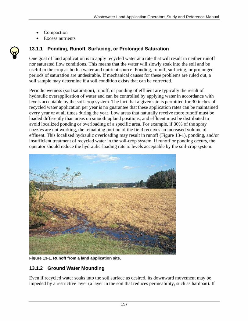
Wastewater Land Application Operators Study and Reference Manual
157
Compaction
Excess nutrients
13.1.1 Ponding, Runoff, Surfacing, or Prolonged Saturation
One goal of land application is to apply recycled water at a rate that will result in neither runoff
nor saturated flow conditions. This means that the water will slowly soak into the soil and be
useful to the crop as both a water and nutrient source. Ponding, runoff, surfacing, or prolonged
periods of saturation are undesirable. If mechanical causes for these problems are ruled out, a
soil sample may determine if a soil condition exists that can be corrected.
Periodic wetness (soil saturation), runoff, or ponding of effluent are typically the result of
hydraulic overapplication of water and can be controlled by applying water in accordance with
levels acceptable by the soil-crop system. The fact that a given site is permitted for 30 inches of
recycled water application per year is no guarantee that these application rates can be maintained
every year or at all times during the year. Low areas that naturally receive more runoff must be
loaded differently than areas on smooth upland positions, and effluent must be distributed to
avoid localized ponding or overloading of a specific area. For example, if 30% of the spray
nozzles are not working, the remaining portion of the field receives an increased volume of
effluent. This localized hydraulic overloading may result in runoff (Figure 13-1), ponding, and/or
insufficient treatment of recycled water in the soil-crop system. If runoff or ponding occurs, the
operator should reduce the hydraulic-loading rate to levels acceptable by the soil-crop system.
Figure 13-1. Runoff from a land application site.
13.1.2 Ground Water Mounding
Even if recycled water soaks into the soil surface as desired, its downward movement may be
impeded by a restrictive layer (a layer in the soil that reduces permeability, such as hardpan). If
Wastewater Land Application Operators Study and Reference Manual
158
so, additional irrigation events can cause the subsurface saturated zone to rise in the soil,
resulting in ground water mounding.
Depending on soil type, 1 to 3 feet of unsaturated soil are typically needed for recycled water
treatment. If mounding results in saturated conditions within 3 feet of the soil surface, anaerobic
conditions in the root zone can limit the growth potential of crops, resulting in insufficient
treatment of recycled water because the water may flow laterally or surface at the ground.
The WWLA operator can readily check the level of a perched water table in fields or areas of
concern:
During times of expected high water levels in soils, an auger or posthole digger can be
used to open a hole in the soil to the depth of interest. Usually, a hole 18 inches deep will
be sufficient to indicate whether the soil surface is saturated.
Sufficient time should be allowed for the soil water to move into the hole, generally an
hour or so. If the water level is within 12 inches of the soil surface, water additions
(rainfall or irrigation) may result in rapid lateral subsurface flow, ponding, anaerobic
conditions for the crop roots, and potential for runoff or discharge of recycled water.
A more permanent monitoring device can be established by inserting a piece of perforated plastic
pipe with a removable cap into the soil. This monitoring device should be marked, so it is not
damaged by equipment, or set at grade level and marked with flagging or orange paint. Such
simple devices can easily assist the WWLA operator in making irrigation decisions that protect
the soil-crop system from saturation.
13.1.3 Surface Crusting
Poor management practices can result in surface crusting that forms a relatively impermeable
layer at the soil surface. Such a layer can be created by excessive thatch, improper application of
organic matter, and destruction of surface soil aggregates.
13.1.3.1 Surface Crusting Caused by Thatch
One cause of surface crusting that is often overlooked is the accumulation of thatch, which is a
layer of dead and living grass shoots, stems, and roots. Excessive thatch buildup can result in
reduced infiltrative capacity of the soil, acting as a barrier to added water. It can also serve to
block the transfer of air (oxygen) to plant roots, causing further stress to the crop. In extreme
conditions, anaerobic activity or algae growth can occur on the thatch buildup: an organic or
slime layer may form a clogging mat and further decrease water infiltration. If a large enough
portion of the site is affected, the result is increased load on the remainder of the site. For all
these reasons, thatch buildup should be monitored and removed promptly if a problem is noted.
It is easier to prevent thatch buildup than to try to remove it. Prevention can be accomplished by
frequent mowing, removing mowed vegetation, and operating the site so that wet conditions at
the soil surface are not chronic. Thatch removal may be performed with special rakes or soil
aeration tools. In extreme cases, disking the field or a complete replanting may be necessary.
Since these activities result in significant damage or removal of the crop, some start-up time is
required with a new crop, during which irrigation volumes must be reduced due to the potential
of increased runoff and soil erosion.
Wastewater Land Application Operators Study and Reference Manual
159
13.1.3.2 Surface Crusting Caused by Improper Application of Organic Matter
As discussed, organic matter is found in most wastewaters. It may be in the form of large
suspended solids, dissolved carbonaceous compounds, or both.
If improperly applied to the soil surface, suspended solids in recycled water may also generate a
clogging mat, composed primarily of anaerobic bacteria, on the soil surface reducing infiltration
into the soil, which may cause runoff or ponding. Once established, this slime limits the
exchange of oxygen in the soil, and anaerobic conditions will develop under the soil surface. If
these problems exist, collecting a soil sample may determine if the soil condition can be
corrected.
Oxygen transport into and through the soil is critical for the degradation of organic additions. If
recycled water is to receive sufficient treatment, it is essential that the soil drain adequately.
Under waterlogged conditions, oxygen diffusion may be severely restricted. Sufficient time is
needed for the oxygen to diffuse into the soil and for the microbial degradation to occur.
Hence, the irrigation frequency is quite important and organic overloading can occur if the above
hydraulic-loading factors are not properly managed.
13.1.3.3 Soil Crusting Caused by Destruction of Surface Soil Aggregates
Soil crusting can also be caused by destruction of surface soil aggregates, especially when soil is
exposed and left bare to heavy rains. High SAR or sodium in soils can also cause destruction of
surface soil aggregates. Destruction of surface soil aggregates may result in fine soil particles.
Fine soil particles disperse and seal the soil surface, which can become impermeable to
infiltration if areas of bare soil occur at the land application site. Once soils become crusted, it
can be difficult to establish plants or seedlings.
13.1.3.4 Dealing with Surface Crusting
In areas where crusting has occurred, it is important to restore aeration to the plant root zone and
to provide favorable conditions for crops as well as for soil microorganisms involved in recycled
water treatment. Surface crusting can be easily reversed by mechanical tillage to break up the
soil surface or by raking to remove thatch.
However, because additional traffic increases the potential for compaction of subsurface layers,
the crust should be broken using the lightest possible equipment, and the area must be reseeded.
Any efforts to reestablish crops on areas of crusted soils or thatch buildup should be performed at
the most ideal time for planting the crop that is to be used.
13.1.4 Compaction
As discussed in section 6.2.2, heavy traffic (especially on wet soils) can cause soil compaction,
destroy soil pores, and reduce aeration and the effective permeability of the soil profile. Both
surface and subsurface drainage and aeration are essential to maintain an aerobic soil
environment suitable for recycled water treatment. The maintenance of a stable soil structure is
an important means of maintaining good drainage and aeration. Therefore, traffic over a land
application field should be limited to (1) equipment or vehicles that are absolutely necessary for

Wastewater Land Application Operators Study and Reference Manual
160
operation and maintenance and (2) after soils have properly drained to avoid unnecessary
compaction.
Once soil is compacted, tillage may be necessary. One of the principal objectives of tillage
operations is to maintain or enhance the water infiltration capacity of the soil surface as well as
the air exchange within the entire soil profile. It may be necessary to chisel very deeply (1.5 to
2.0 feet) to loosen the subsoil. Impermeable pans formed by vehicular traffic (plow pan) or by
cementation of fine particles (hardpan) can be broken up by subsoiling equipment that leaves the
surface undisturbed and protected by vegetation or stubble. To be effective, however, the
subsoiling equipment must completely break through the pan layers. This is difficult if the pan
layers are more than 1 foot thick.
Local soil conservation district personnel should be consulted regarding tillage practices
appropriate for specific crops, soils, and terrain.
13.1.5 Excess Recycled Water Constituents
Monitoring the flow and constituent concentrations of the recycled water are typical
requirements of a reuse permit, so the concentration of constituents in the recycled water and the
expected volume should be analyzed prior to site evaluation to estimate potential land
application area requirements. Metals, such as copper, zinc, and manganese, or other
components, such as salts, pH, oils and grease, and organic and inorganic chemicals may prove
to be limiting, depending on the site soils and the crops planted at the land application site.
Likewise, if the plant species is changed, recycled water characteristics must be assessed to
determine if the selected plants are appropriate. When selecting crops, the amount of water that
the crop needs for optimum growth must also be considered.
Significant levels of certain recycled water constituents may indicate the need for additional
treatment prior to land application. It is beyond the scope of this manual to discuss all possible
limitations that may be encountered with a land application site.
13.1.5.1 Excess Salts
The application of water containing soluble salts, such as chlorides, sulfates, potassium, calcium,
manganese, and especially sodium, can be detrimental not only to the crops being grown on the
site but to the soils as well. A buildup of sodium in the soil can reduce the permeability of the
soil by causing dispersion of the clay minerals. Reduced permeability often results in poor
internal soil drainage and aeration, which can cause stress to crops as well as ponding and
waterlogged soils that do not provide adequate treatment. Municipal recycled water generally
does not have high salts, however, industrial recycled water may be high in salt and salt loading
should be managed.
It may be possible (but difficult) to renovate soils with high sodium concentrations. If the
recycled water at your site has high salts, it is preferable to prevent the problem before it occurs
by monitoring recycled water and soils for sodium and taking action before problems levels are
reached. Salts can affect soil and vegetation in several ways:
Wastewater Land Application Operators Study and Reference Manual
161
Adversely affect soil structure
Upset soil-water balance and interfere with plant root growth, ability to take up water and
nutrients, and reduce crop yields
Leach to ground water
Affect or reduce seed germination
The detrimental effects on plants result not only from the high salt contents but also from the
level of sodium in the soil, especially in relation to levels of calcium and magnesium. To
understand the management options to restore or prevent damage to the soil, the WWLA
operator must first understand the difference between saline and sodic soils.
13.1.5.2 Saline Versus Sodic Soils
Saline soils contain concentrations of neutral soluble salts (such as sodium or potassium)
sufficient to interfere with the growth of most plants. When large amounts of dissolved salts are
brought into contact with a plant cell, water will pass by osmosis from the cell into the more
concentrated salt solution. The cell then collapses, ultimately leading to cell death and eventually
plant death.
Sodic soils, dominated by active sodium, exert a detrimental effect on plants in four ways:
1. Caustic influence of the high pH, induced by the formation of sodium carbonate and
bicarbonate
2. Toxicity of the bicarbonate and other anions
3. The adverse effects of the active sodium ions on plant metabolism and nutrition and the
low micronutrient availability due to high pH
4. Oxygen deficiency due to breakdown of soil structure in sodium-dominated soils
The influence of soil pH on land application activities is further discussed in section 6.3.4.
13.1.5.3 Plant Tolerance
Plant tolerance to saline and sodic soils depends on a number of interrelated factors, including
the physiological constitution of the plant, its stage of growth, and its rooting habits. It is
interesting to note that old alfalfa is more tolerant of salt-affected soils than young alfalfa, and
that deep-rooted legumes show a greater resistance to such soils than the shallow-rooted ones
(Brady and Weil 2008).
13.1.5.4 Evaluating Soils Conditions: Sodium Adsorption Ratio
To evaluate the condition of the soil, the nature of the various salts and their proportionate
amounts, total concentration, and distribution in the soil profile must be considered. The
structure of the soil and its drainage and aeration are important as well.
Prevention of the problem is very important. Once sodium and salt damage occurs to the soil, it
is a slow and tedious procedure to restore the soil to its original condition. To prevent such
damage, it is helpful to know the sodium concentration in the water.
As discussed in section 6.3.3, a ratio of the sodium concentration to the concentrations of
calcium and magnesium is called the sodium adsorption ratio (SAR), and the value of this ratio
Wastewater Land Application Operators Study and Reference Manual
162
is a good indicator of potential soil problems. For soils, the SAR test is run on a saturated paste
extraction of the soil. The SAR test may also be run on a recycled water sample.
SARs in recycled water range from very low (less than 1) to several hundred. Industries that are
especially prone to having SAR problems are the food processing industry, industries that use
sodium hydroxide as a wash or disinfectant, or other operations using a form of sodium. A SAR
of 13 for a solution extract from a saturated soil paste is generally considered an upper level for
safe operation. However, many variables go along with the SAR that will determine if problems
will be expressed in the soil.
At an SAR value of 10 or more, attention should be given to the sodium issue to ensure that
future problems can be minimized and the WWLA operator should determine if excess sodium
in the recycled water stream can be reduced. Soil samples should also be analyzed for SAR to
help determine if the soil sodium activity level is approaching a problem level. Individuals with
technical expertise should be contacted if the WWLA operator is not experienced with these
issues.
13.1.5.5 Evaluating Soil Conditions: Exchangeable Sodium Percentage
Exchangeable sodium percentage (ESP) is another evaluation that can be used to determine
possible excess sodium concentration in the soil itself. The ESP is the percentage of the soil’s
CEC that is occupied by the sodium cations. The ESP can be determined from a typical soil
fertility evaluation (Equation 13-1).
%100*CEC
ionconcentrat Na ESP
Equation 13-1. Calculating exchangeable sodium percentage.
An ESP level of 15% or higher is typically used to denote a level of concern (representative of
sodic soils), where salt damage may occur both to the crop and to the soil structure resulting in
loss of soil infiltration and recycled water ponding (an ESP level of 15 is approximately equal to
an SAR of 13 for a solution extracted from a saturated soil paste) (Brady and Weil 2008). Due to
the fact that SAR values are easier to obtain, the use of ESP has become less popular in recent
years.
13.1.5.6 Evaluating Soil Conditions: Electrical Conductivity
Electrical conductivity is an indirect measure of soil salts. Pure water is a poor conductor of
electricity, however, conductivity increases as salts are dissolved in water. Therefore, electrical
conductivity is a measure of soil salinity. The most common method to determine electrical
conductivity is saturation paste extract method and is the standard to which other methods are
compared. Typically when determining soil structure or infiltration problems at a land
application site, it is beneficial to look at both SAR and electrical conductivity. Table 13-1 lists
typical water quality guidelines for recycled water that may have high salt concentrations.
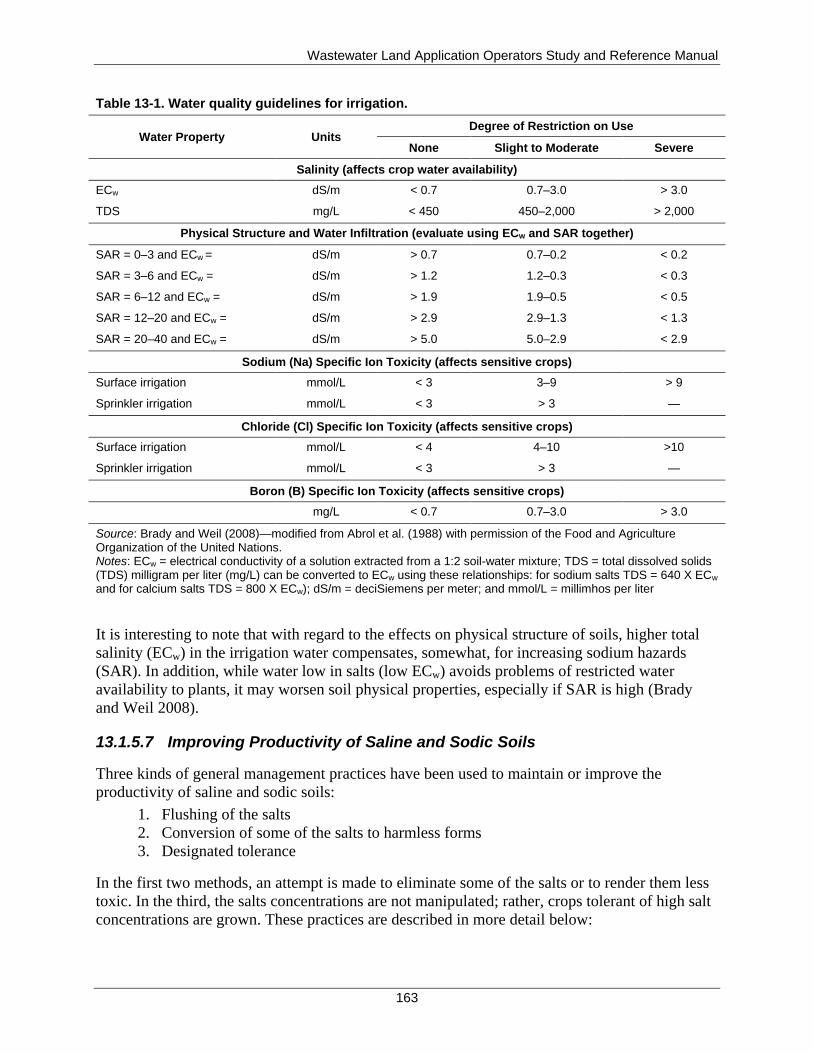
Wastewater Land Application Operators Study and Reference Manual
163
Table 13-1. Water quality guidelines for irrigation.
Water Property Units Degree of Restriction on Use
None Slight to Moderate Severe
Salinity (affects crop water availability)
ECw dS/m < 0.7 0.7–3.0 > 3.0
TDS mg/L < 450 450–2,000 > 2,000
Physical Structure and Water Infiltration (evaluate using ECw and SAR together)
SAR = 0–3 and ECw = dS/m > 0.7 0.7–0.2 < 0.2
SAR = 3–6 and ECw = dS/m > 1.2 1.2–0.3 < 0.3
SAR = 6–12 and ECw = dS/m > 1.9 1.9–0.5 < 0.5
SAR = 12–20 and ECw = dS/m > 2.9 2.9–1.3 < 1.3
SAR = 20–40 and ECw = dS/m > 5.0 5.0–2.9 < 2.9
Sodium (Na) Specific Ion Toxicity (affects sensitive crops)
Surface irrigation mmol/L < 3 3–9 > 9
Sprinkler irrigation mmol/L < 3 > 3 —
Chloride (Cl) Specific Ion Toxicity (affects sensitive crops)
Surface irrigation mmol/L < 4 4–10 >10
Sprinkler irrigation mmol/L < 3 > 3 —
Boron (B) Specific Ion Toxicity (affects sensitive crops)
mg/L < 0.7 0.7–3.0 > 3.0
Source: Brady and Weil (2008)—modified from Abrol et al. (1988) with permission of the Food and Agriculture Organization of the United Nations. Notes: ECw = electrical conductivity of a solution extracted from a 1:2 soil-water mixture; TDS = total dissolved solids (TDS) milligram per liter (mg/L) can be converted to ECw using these relationships: for sodium salts TDS = 640 X ECw
and for calcium salts TDS = 800 X ECw); dS/m = deciSiemens per meter; and mmol/L = millimhos per liter
It is interesting to note that with regard to the effects on physical structure of soils, higher total
salinity (ECw) in the irrigation water compensates, somewhat, for increasing sodium hazards
(SAR). In addition, while water low in salts (low ECw) avoids problems of restricted water
availability to plants, it may worsen soil physical properties, especially if SAR is high (Brady
and Weil 2008).
13.1.5.7 Improving Productivity of Saline and Sodic Soils
Three kinds of general management practices have been used to maintain or improve the
productivity of saline and sodic soils:
1. Flushing of the salts
2. Conversion of some of the salts to harmless forms
3. Designated tolerance
In the first two methods, an attempt is made to eliminate some of the salts or to render them less
toxic. In the third, the salts concentrations are not manipulated; rather, crops tolerant of high salt
concentrations are grown. These practices are described in more detail below:
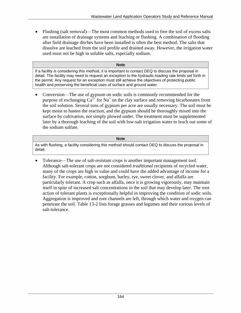
Wastewater Land Application Operators Study and Reference Manual
164
Flushing (salt removal)—The most common methods used to free the soil of excess salts
are installation of drainage systems and leaching or flushing. A combination of flooding
after field drainage ditches have been installed is often the best method. The salts that
dissolve are leached from the soil profile and drained away. However, the irrigation water
used must not be high in soluble salts, especially sodium.
Note
If a facility is considering this method, it is important to contact DEQ to discuss the proposal in detail. The facility may need to request an exception to the hydraulic-loading rate limits set forth in the permit. Any request for an exception must still achieve the objectives of protecting public health and preserving the beneficial uses of surface and ground water.
Conversion—The use of gypsum on sodic soils is commonly recommended for the
purpose of exchanging Ca2+
for Na+ on the clay surface and removing bicarbonates from
the soil solution. Several tons of gypsum per acre are usually necessary. The soil must be
kept moist to hasten the reaction, and the gypsum should be thoroughly mixed into the
surface by cultivation, not simply plowed under. The treatment must be supplemented
later by a thorough leaching of the soil with low-salt irrigation water to leach out some of
the sodium sulfate.
Note
As with flushing, a facility considering this method should contact DEQ to discuss the proposal in detail.
Tolerance—The use of salt-resistant crops is another important management tool.
Although salt-tolerant crops are not considered traditional recipients of recycled water,
many of the crops are high in value and could have the added advantage of income for a
facility. For example, cotton, sorghum, barley, rye, sweet clover, and alfalfa are
particularly tolerant. A crop such as alfalfa, once it is growing vigorously, may maintain
itself in spite of increased salt concentrations in the soil that may develop later. The root
action of tolerant plants is exceptionally helpful in improving the condition of sodic soils.
Aggregation is improved and root channels are left, through which water and oxygen can
penetrate the soil. Table 13-2 lists forage grasses and legumes and their various levels of
salt-tolerance.
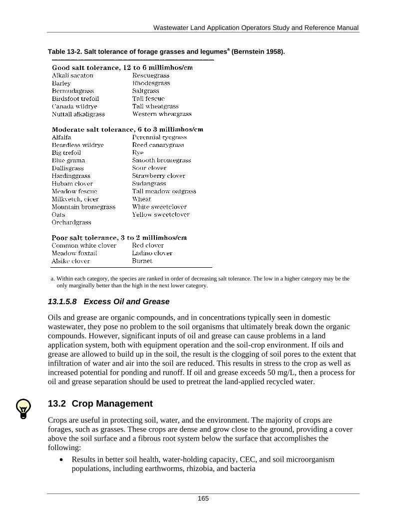
Wastewater Land Application Operators Study and Reference Manual
165
Table 13-2. Salt tolerance of forage grasses and legumesa (Bernstein 1958).
a. Within each category, the species are ranked in order of decreasing salt tolerance. The low in a higher category may be the
only marginally better than the high in the next lower category.
13.1.5.8 Excess Oil and Grease
Oils and grease are organic compounds, and in concentrations typically seen in domestic
wastewater, they pose no problem to the soil organisms that ultimately break down the organic
compounds. However, significant inputs of oil and grease can cause problems in a land
application system, both with equipment operation and the soil-crop environment. If oils and
grease are allowed to build up in the soil, the result is the clogging of soil pores to the extent that
infiltration of water and air into the soil are reduced. This results in stress to the crop as well as
increased potential for ponding and runoff. If oil and grease exceeds 50 mg/L, then a process for
oil and grease separation should be used to pretreat the land-applied recycled water.
13.2 Crop Management
Crops are useful in protecting soil, water, and the environment. The majority of crops are
forages, such as grasses. These crops are dense and grow close to the ground, providing a cover
above the soil surface and a fibrous root system below the surface that accomplishes the
following:
Results in better soil health, water-holding capacity, CEC, and soil microorganism
populations, including earthworms, rhizobia, and bacteria

Wastewater Land Application Operators Study and Reference Manual
166
Reduces the impact of raindrops on the soil surface, decreasing soil crusting, water
runoff, and movement of soil particles off site, thus less movement of fertilizer and
pesticides into streams
Extends the amount and depth of root exploration of the soil volume, which indirectly
relates to plant water use and nutrient uptake
Establishing and maintaining vegetative cover should be one of the highest priorities of the
WWLA operator. The WWLA operator should routinely examine the health of the vegetative
cover and take immediate action if there is a problem. Prevention is generally easier than
remediation when it comes to plant health. Once plants begin to show stress, the problem is often
well established and may require significant time and effort to correct.
Crops can be stressed by excessive water or by a lack of sufficient water. As discussed earlier in
this section, crops can be stressed by excessive nutrient or salt applications. Conversely, crops
can be stressed or damaged by insufficient plant nutrients or improper soil pH. Other factors
include soil compaction and damage by maintenance equipment. The WWLA operator must be
aware of the requirements of the crops and attempt to meet these requirements with a crop
management plan. Such a plan will minimize the potential that the crops will be the limiting
factor for system operation (Figure 13-2).
Figure 13-2. Poor crop stand in a fescue pasture. The lighter areas indicate stunted or dying vegetation.
Maintaining good crop growing conditions will reduce both surface runoff losses and subsurface
losses of plant nutrients and will allow the recycled water system to perform as designed. Crop
management involves the following activities:
Crop selection
Nutrient and irrigation management
Soil fertility management
Wastewater Land Application Operators Study and Reference Manual
167
Pest control
BMPs
Troubleshooting
13.2.1 Crop Selection
Important factors in the selection of crops for land application systems include the following:
Nutrient requirements of the crops
Time and length of the growing season
End use of the crop
Crop management requirements
Water tolerance of the crop
Use of seasonal overseeds
Soil type
Local climate conditions
Using trees as a crop
13.2.1.1 Nutrient Requirements
The nutrient requirements of a crop impact system operation in terms of expense and time. If
crops can be economically grown for harvest, such as in a commercial farming setting, and if the
use of supplemental fertilizers is appropriate for the site, the time and cost expended fertilizing
crops can be justified. Some crops are more tolerant of nutrient imbalances than others, but all
crops will need some attention to maintain the health of the plants and ensure proper system
operation. In selecting crops, consult an agricultural manual that shows crop nutrient needs and
timing during the growing season. Table 13-3 lists general nitrogen fertilization guidelines for
various forage crops.
Table 13-3. Nitrogen fertilization guidelines (Zublena et al. 1996).
13.2.1.2 Growing Season Time and Length
Ideally, the crops grown should be selected to fit the times when recycled water is generated and
application is required. A mixture of crop types may offer the WWLA operator flexibility in
system management.
Wastewater Land Application Operators Study and Reference Manual
168
13.2.1.3 Crop End Use
To keep a cropping system viable, it must be harvested at regular intervals. If there is no end use
for the crop, less attention may be given to the crop's needs, possibly resulting in poor system
management. Therefore, having a use for the crop should be a goal of the permittee and WWLA
operator. If forage crops are mowed and baled, and simply left in the field to rot, the nutrients are
returned back to the site and not removed. Hay bales can be sold for use as mulch or livestock
feed. Compost can be made for use by the public. Crops with higher cash value can simply be
sold as is. Wood products have infrequent harvest intervals, but a market should be planned for if
those products are selected for use at the site.
13.2.1.4 Crop Management Requirements
Crops should be selected with a good understanding of their maintenance requirements. Is the
crop perennial, or must it be replanted every year or two? Does it require multiple harvests
during the year? Does the crop require nutrient applications two times per year or eight times per
year? Are there other tedious tasks that need to be performed in order for the crop to stay
healthy?
Generally, the simpler the maintenance scheme for a crop, the better it can be managed.
13.2.1.5 Crop Water Tolerance
A crop that cannot tolerate the expected combination of applied recycled water and precipitation
at the site should not be used. Crop water tolerance may be a consideration in the wetter parts of
the state such as northern Idaho. Some crops cannot tolerate soil saturation for very long, while
other crops and grasses may even thrive in such conditions. Examples of crops, grasses, and trees
that are especially water-tolerant include reed canary grass, ryegrass, common Bermuda grass,
tall fescue, sweetgum, sycamore, and bald cypress. Examples of crops that are very susceptible
to soil wetness problems include alfalfa and corn.
13.2.1.6 Seasonal Overseed Use
Forage grasses can be classified as cool season or warm season. No grass crop covers both
categories.
Cool season grasses grow actively in the spring and fall. They may go dormant in the summer.
Warm season grasses grow actively from mid-April through October 1 and are dormant through
the winter.
If these seasonal crops are used, other grasses may be used temporarily as an overseed to help
with nutrient uptake. For example, winter rye (a cool season grass) can be used as an overseed
with Bermuda grass. Some forage species are not tolerant of this arrangement, and an overseeded
species may seriously damage the main crop. Examples of grasses, forages, or grains that should
be avoided as an overseed include gama grass, switch grass, or bluestems.
Wastewater Land Application Operators Study and Reference Manual
169
13.2.1.7 Soil Type
The crop selected must be adapted to the soil types on the site. On a large site, it is likely that
several soil types exist; therefore, it may be necessary to use several crop types. Soils with heavy
clay will stay wet longer after irrigation and rainfall events, and the crops must be able to handle
these conditions. Sandy soils do not hold water and nutrients; therefore, a drought-tolerant crop
will survive better, and split applications of fertilizer may be needed.
13.2.1.8 Local Climatic Conditions
The crop must also be adapted to the local area. Sometimes, crops are selected for their nutrient
removal ability or ability to withstand wet conditions, but they may not tolerate the soils or
climate. All factors must be considered when selecting a crop that can adapt to the site and
recycled water applications and can be managed efficiently.
13.2.1.9 Using Trees as Crops
Using trees as crops at land application sites is increasing in popularity. Application of recycled
water to forestland offers a viable alternative for the beneficial reuse of nutrients, and other
constituents, while producing marketable wood products.
Under short rotations, trees can be whole-tree harvested, removing the nutrients from the site in a
nonfood chain product. Under medium to longer rotations, high value solid-wood products, such
as lumber or veneer can be grown.
Crop possibilities include ornamental trees and shrubs (ball and burlap) grown for 3 to 6 years
and removed as thinnings or as an entire crop. For harvested tree crops, a second rotation will
result from coppice (sprouts) from the existing root systems. Coppicing will result in
intermediate tree cover and a continuance of vegetative cover on the site without replanting.
Phosphorus uptake in trees also compares favorably to high yield grass crops. Prior to using
recycled water for tree irrigation, a silvicultural plan (a plan covering the care and cultivation of
the trees) is prepared by a qualified silviculturist and is reviewed and approved by DEQ.
13.2.2 Nutrient and Irrigation Management
Once a crop has been selected, it must be established and properly managed to ensure that the
crop thrives and functions as an efficient component of the treatment system:
Crops should be planted at the best possible time. Time of planting is important because
the survival rate of developing seedlings is related to the time at which stress occurs from
drought, freezing, or competition for light and nutrients. If no such stress occurs, or if it
occurs after seedlings are well established, survival and production losses can be
minimized.
Although many of the nutrients required by crops can be supplied through recycled water
application, recycled water may not supply all the necessary plant nutrients. Nutrient
application rates and application timing must be appropriate for the selected crop.
Receiver crops vary in their ability to use nutrients. In systems where the water has high
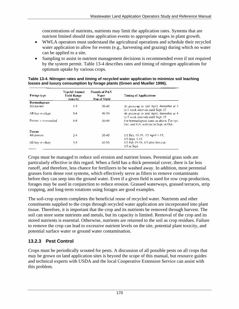
Wastewater Land Application Operators Study and Reference Manual
170
concentrations of nutrients, nutrients may limit the application rates. Systems that are
nutrient limited should time application events to appropriate stages in plant growth.
WWLA operators must understand the agricultural operations and schedule their recycled
water application to allow for events (e.g., harvesting and grazing) during which no water
can be applied to a site.
Sampling to assist in nutrient management decisions is recommended even if not required
by the system permit. Table 13-4 describes rates and timing of nitrogen applications for
optimum uptake by various crops.
Table 13-4. Nitrogen rates and timing of recycled water application to minimize soil leaching losses and luxury consumption by forage plants (Green and Mueller 1996).
Crops must be managed to reduce soil erosion and nutrient losses. Perennial grass sods are
particularly effective in this regard. When a field has a thick perennial cover, there is far less
runoff, and therefore, less chance for fertilizers to be washed away. In addition, most perennial
grasses form dense root systems, which effectively serve as filters to remove contaminants
before they can seep into the ground water. Even if a given field is used for row crop production,
forages may be used in conjunction to reduce erosion. Grassed waterways, grassed terraces, strip
cropping, and long-term rotations using forages are good examples.
The soil-crop system completes the beneficial reuse of recycled water. Nutrients and other
constituents supplied to the crops through recycled water application are incorporated into plant
tissue. Therefore, it is important that the crop and its nutrients be removed through harvest. The
soil can store some nutrients and metals, but its capacity is limited. Removal of the crop and its
stored nutrients is essential. Otherwise, nutrients are returned to the soil as crop residues. Failure
to remove the crop can lead to excessive nutrient levels on the site, potential plant toxicity, and
potential surface water or ground water contamination.
13.2.3 Pest Control
Crops must be periodically scouted for pests. A discussion of all possible pests on all crops that
may be grown on land application sites is beyond the scope of this manual, but resource guides
and technical experts with USDA and the local Cooperative Extension Service can assist with
this problem.
Wastewater Land Application Operators Study and Reference Manual
171
Any individual responsible for purchasing and applying restricted pesticides must be licensed by
the State of Idaho. Restricted use pesticides must be used in accordance with label directions,
and only licensed applicators can apply certain restricted use products.
Pesticides in ground water may result from spills or backsiphoning that can occur when
pesticides are mixed or loaded. These problems present point sources, or small areas of high
concentrations of pesticides that can contaminate large areas of ground water over time. Point
source contamination can be located and cleaned up.
Good construction and maintenance of the pesticide mixing and loading area can prevent most of
these problems, but pesticides may also be making their way into ground water from fields where
they are applied. Applied pesticides can leach or move through the soil with water as it
percolates down to ground water. The likelihood of a pesticide moving downward depends
largely on its solubility, or its ability to dissolve in water. If a pesticide is highly soluble, it is
more likely to reach the ground water. On the other hand, many pesticides, even some that are
soluble, are likely to stick to soil particles by adsorption. Thus, if the probability of adsorption is
high, less of the pesticides will leach.
Proper management of pesticides should be practiced to protect our water supplies. When
applying pesticides, make sure that it is not a restricted pesticide. A restricted pesticide requires a
licensed applicator. If applying a nonrestricted pesticide do the following:
Read container labels correctly.
Use the lowest effective rate listed on the label for any one application; the assumption
that "if a little will do a little good, a lot will do a lot of good" is a fallacy.
Correctly identify pests, so that you use the proper pesticide and do not wastefully apply
inappropriate materials.
Sweep small amounts of fertilizer or pesticide granules that may fall on impervious areas,
such as sidewalks and driveways, into a vegetated area.
Calibrate spreaders and sprayers, so that you know how much pesticide you are applying
to an area.
Learn about alternative pest control measures, such as beneficial insects, crop rotation,
residue destruction, varietal resistance, proper planting dates, and companion cropping
systems that may be good alternatives for your pest management problem.
For more information about pesticides application, contact the local Cooperative Extension
Service.
13.2.4 Best Management Practices
A best management practice (BMP) can be any practice that reduces the movement of waste
products (including odors) away from the land application site, and into ground or surface water
or to other properties. BMPs are structural or operational practices that help to operate a land
application system with the least chance of negative impacts on the environment. The most
commonly used operational BMP to control runoff at a land application site is maintaining
hydraulic-loading rates within levels acceptable by the soil-crop system. Crops and crop
residues, cultural practices, and structures are used, alone or in combination, to hold the soil in
place and allow water to move into it rather than to run off the surface.
Wastewater Land Application Operators Study and Reference Manual
172
BMPs relating to nutrient management are those practices that optimize nutrient uptake by plants
and minimize nutrient impact on the environment. BMPs are site specific; a BMP in one place
may not offer the same benefits in another location. Therefore, specific BMPs may or may not be
mandated in regulatory documents. A trained agronomist or soil scientist is the best resource to
assess whether a particular BMP is appropriate for your situation if it is not already included as a
condition of the system permit.
BMPs at a land application site may include the following:
Perform soil tests—Nutrients should be applied to soils only as necessary. To know the
soil's nutrient-supplying capacity, have it analyzed by a soil test laboratory that uses
testing procedures developed specifically for the soil conditions.
Follow soil test recommendations—A soil test report indicates the amount of nutrients
that the soil can supply and recommends the amount, if any, needed from other sources.
The test also recommends appropriate amendments (such as lime or sulfur) to adjust soil
pH to the proper range for the best crop growth. Soil deficiencies impact crops and
deficiency of one nutrient or an undesirable soil pH will limit crop response to the other
nutrients.
Set realistic yield goals—All fertilizer recommendations assume a certain yield goal for
the crop to be grown. Some laboratories ask for the goal, whereas others use an average
number. The yield history of a field is the best guide to realistic expectations. Also,
county soil surveys include crop yield estimates by soil series. Factors, such as the soil's
moisture supplying capacity, should be considered.
Do not overapply nutrients in the quest for unrealistic yields—Applying excessive
amounts of nutrients can contribute to water pollution. For example, overapplying
nitrogen is especially risky, since it can easily be lost from the soil.
Apply nitrogen and phosphorus correctly—Nitrogen and phosphorus from fertilizer
application are less likely to be lost by erosion or runoff if they are banded directly into
the soil or applied to the soil surface and promptly mixed into the soil by disking,
plowing, or rotary tilling. Subsurface banding also makes it possible for nutrients to be
placed where the crop can make the best use of them.
Do not apply nitrogen and phosphorus to soil surface without incorporation—This
method is the least desirable way to apply fertilizer, but it is often used for pastures,
lawns, turf, and other perennial crops. Because phosphorus is relatively immobile,
phosphorus should be incorporated into the soil before perennial crops are established.
Where surface application is unavoidable, minimize the use of phosphorus. Aeration
equipment can be used to improve soil infiltration and nutrient movement into the soil.
The application method (surface applied or banded) has little effect on losses of nitrogen
by leaching.
Time nitrogen applications appropriately—Application timing is more important with
nitrogen than with any other nutrient. If nitrogen is applied in large amounts to crops the
mobile nitrate form may move to ground water. Phosphorus, on the other hand, is more
stable once it is mixed into the soil and can be applied when most convenient. Timing of
nutrient application to coincide with plant growth requirements increases uptake
efficiency and reduces exposure of applied nutrients to surface runoff and subsurface
leaching. Optimum application time depends on crop type, climate, soil conditions, and
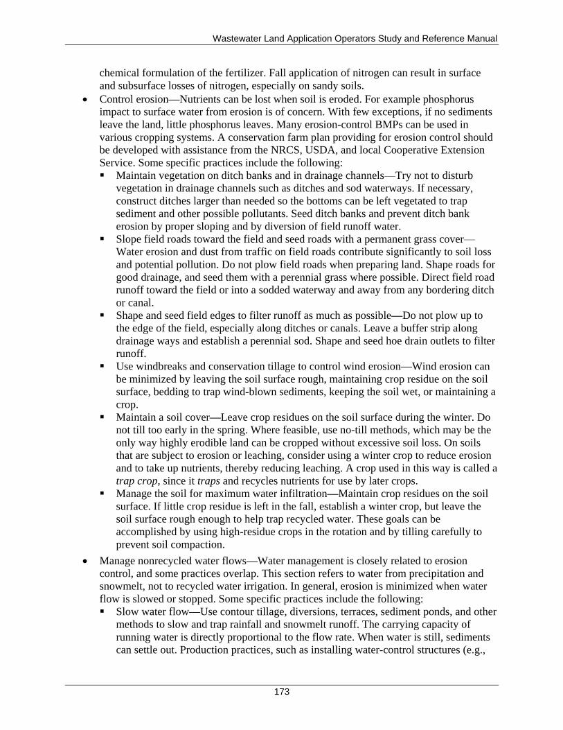
Wastewater Land Application Operators Study and Reference Manual
173
chemical formulation of the fertilizer. Fall application of nitrogen can result in surface
and subsurface losses of nitrogen, especially on sandy soils.
Control erosion—Nutrients can be lost when soil is eroded. For example phosphorus
impact to surface water from erosion is of concern. With few exceptions, if no sediments
leave the land, little phosphorus leaves. Many erosion-control BMPs can be used in
various cropping systems. A conservation farm plan providing for erosion control should
be developed with assistance from the NRCS, USDA, and local Cooperative Extension
Service. Some specific practices include the following:
Maintain vegetation on ditch banks and in drainage channels—Try not to disturb
vegetation in drainage channels such as ditches and sod waterways. If necessary,
construct ditches larger than needed so the bottoms can be left vegetated to trap
sediment and other possible pollutants. Seed ditch banks and prevent ditch bank
erosion by proper sloping and by diversion of field runoff water.
Slope field roads toward the field and seed roads with a permanent grass cover—
Water erosion and dust from traffic on field roads contribute significantly to soil loss
and potential pollution. Do not plow field roads when preparing land. Shape roads for
good drainage, and seed them with a perennial grass where possible. Direct field road
runoff toward the field or into a sodded waterway and away from any bordering ditch
or canal.
Shape and seed field edges to filter runoff as much as possible—Do not plow up to
the edge of the field, especially along ditches or canals. Leave a buffer strip along
drainage ways and establish a perennial sod. Shape and seed hoe drain outlets to filter
runoff.
Use windbreaks and conservation tillage to control wind erosion—Wind erosion can
be minimized by leaving the soil surface rough, maintaining crop residue on the soil
surface, bedding to trap wind-blown sediments, keeping the soil wet, or maintaining a
crop.
Maintain a soil cover—Leave crop residues on the soil surface during the winter. Do
not till too early in the spring. Where feasible, use no-till methods, which may be the
only way highly erodible land can be cropped without excessive soil loss. On soils
that are subject to erosion or leaching, consider using a winter crop to reduce erosion
and to take up nutrients, thereby reducing leaching. A crop used in this way is called a
trap crop, since it traps and recycles nutrients for use by later crops.
Manage the soil for maximum water infiltration—Maintain crop residues on the soil
surface. If little crop residue is left in the fall, establish a winter crop, but leave the
soil surface rough enough to help trap recycled water. These goals can be
accomplished by using high-residue crops in the rotation and by tilling carefully to
prevent soil compaction.
Manage nonrecycled water flows—Water management is closely related to erosion
control, and some practices overlap. This section refers to water from precipitation and
snowmelt, not to recycled water irrigation. In general, erosion is minimized when water
flow is slowed or stopped. Some specific practices include the following:
Slow water flow—Use contour tillage, diversions, terraces, sediment ponds, and other
methods to slow and trap rainfall and snowmelt runoff. The carrying capacity of
running water is directly proportional to the flow rate. When water is still, sediments
can settle out. Production practices, such as installing water-control structures (e.g.,
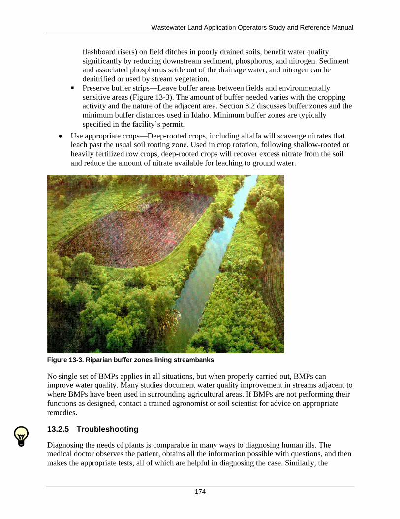
Wastewater Land Application Operators Study and Reference Manual
174
flashboard risers) on field ditches in poorly drained soils, benefit water quality
significantly by reducing downstream sediment, phosphorus, and nitrogen. Sediment
and associated phosphorus settle out of the drainage water, and nitrogen can be
denitrified or used by stream vegetation.
Preserve buffer strips—Leave buffer areas between fields and environmentally
sensitive areas (Figure 13-3). The amount of buffer needed varies with the cropping
activity and the nature of the adjacent area. Section 8.2 discusses buffer zones and the
minimum buffer distances used in Idaho. Minimum buffer zones are typically
specified in the facility’s permit.
Use appropriate crops—Deep-rooted crops, including alfalfa will scavenge nitrates that
leach past the usual soil rooting zone. Used in crop rotation, following shallow-rooted or
heavily fertilized row crops, deep-rooted crops will recover excess nitrate from the soil
and reduce the amount of nitrate available for leaching to ground water.
Figure 13-3. Riparian buffer zones lining streambanks.
No single set of BMPs applies in all situations, but when properly carried out, BMPs can
improve water quality. Many studies document water quality improvement in streams adjacent to
where BMPs have been used in surrounding agricultural areas. If BMPs are not performing their
functions as designed, contact a trained agronomist or soil scientist for advice on appropriate
remedies.
13.2.5 Troubleshooting
Diagnosing the needs of plants is comparable in many ways to diagnosing human ills. The
medical doctor observes the patient, obtains all the information possible with questions, and then
makes the appropriate tests, all of which are helpful in diagnosing the case. Similarly, the
Wastewater Land Application Operators Study and Reference Manual
175
WWLA operator observes the plants, obtains information on past management, and may test the
soil or the plant; the success of the diagnosis depends on the WWLA operator’s understanding of
the fundamentals of plant and soil science and on a correct interpretation of the test results.
Diagnostic measurements of the ailing plant or soil are often referred to as troubleshooting. Plant
and soil samples can and are being used for troubleshooting, but a more important application is
preventive measures. By the time a plant shows stress, it may be too late. To be proactive in crop
management, become familiar with stress symptoms of plants.
Many of the methods for evaluating soil fertility are based on observations of, or measurements
on, growing plants. These methods have considerable merit because the plants act as integrators
of all growth factors (i.e., aeration, fertility, moisture, and pH) and are the products in which the
WWLA operator is interested. Abnormal appearance of the growing plant may be caused by a
deficiency of one or more nutrient elements (Figure 13-4).
If a plant is lacking in a particular element, characteristic symptoms may appear. This visual
method of evaluating soil fertility is unique in that it requires no expensive or elaborate
equipment and can be used as a supplement to other diagnostic techniques (typically the first
indicator of poor crop health). Examples of stress symptoms are as follows:
Complete crop failure at seedling stage
Severe stunting of plants
Specific leaf symptoms such as changes in coloration appearing at varying times during
the season
Delayed or abnormal maturity
Obvious yield differences, with or without leaf symptoms
Poor quality of crops
Poor germination, resulting in reduced stand coverage
Figure 13-4. Sulfur deficiency in corn.
Wastewater Land Application Operators Study and Reference Manual
176
Be aware that in the field it is often difficult to distinguish among the causes of symptoms.
Disease or insect damage frequently resembles certain micronutrient deficiencies; for example,
leaf hopper damage is often confused with boron deficiency in alfalfa.
If symptoms are observed early and are correctly diagnosed, they might be corrected during the
growing season. Crop health may suffer during the first year, but if the trouble is properly
diagnosed, the symptoms may be fully corrected the following year.
If a crop is not present, or is in poor health, the WWLA operator should start the troubleshooting
process. The following steps should be included when attempting to establish a crop or repair an
existing crop:
1. Obtain a representative soil sample.
2. If the crop is present but in poor shape, obtain a plant tissue analysis.
3. Check the area to see if prolonged saturation or soil compaction is a problem.
4. Select a crop or combination of crops suitable for the soil and site conditions, and one
that can be managed in a recycled water application environment.
5. Select a crop that can be used locally or that has some return value.
6. Apply recommended nutrients and/or pH adjustments from the soil test results.
7. Prepare to plant or seed the crop, following all recommendations from the supply store,
or contact the local Cooperative Extension Service.
8. Implement BMPs recommended by a trained agronomist or soil scientist.
13.3 Management of Recycled Water Application
Runoff and/or ponding is a site condition that is typical of hydraulic overloading and can be
avoided by maintaining the hydraulic-loading rate within the levels acceptable by the soil-crop
system.
Irrigation scheduling recommendations discussed in section 11 should be followed.
13.3.1 Uniformity of Recycled Water Distribution
Uniform distribution of recycled water at the land application site is necessary to ensure that the
entire land application site treats the recycled water and to minimize overloading of any
particular area. The WWLA operator should be familiar with the design plans for the facility,
including those design features that are intended to not apply water evenly across a field. These
design features may be required due to changes in soil conditions, slopes, or nearby
drainageways.
In other cases, a site may be designed to receive uniform application across an entire field. The
WWLA operator, however, knows that the system cannot be operated on that field or area at a
uniform application rate without runoff or ponding. Ultimately, the WWLA operator is
responsible for operating the system within the requirements of the permit, which includes
minimizing ponding and runoff.
Note
Any design modifications to the recycled water distribution system must be reviewed and approved by the DEQ.
Wastewater Land Application Operators Study and Reference Manual
177
13.3.1.1 Handling Bleed-off
Areas that are prone to wetness, or hydraulic overload include the heads of drainageways, soils
with less permeable layers, compacted soil areas, areas with poor crops, and areas at the base of
slopes. In most irrigation systems, a condition known as bleed-off is experienced when the
WWLA operator ends an irrigation cycle. The water remaining in the distribution system will
typically run to the lowest lateral and spray nozzle, and recycled water will trickle out of this
nozzle, sometimes for many minutes before the distribution lines are clear. This condition can
result in local overloading and the possibility of ponding or runoff.
The WWLA operator can account for bleed-off in one of two ways:
1. The irrigation cycle can be stopped early enough to anticipate the bleed-off and still have
the soil in the bleed-off area absorb the effluent.
2. The WWLA operator can install hardware to stop or spread out the bleed-off condition to
minimize any localized overload.
13.3.1.2 Handling Chronic Hydraulic Overload
An area that is continually overloaded hydraulically will soon be obvious to the WWLA
operator. The crop in that area may be taller or greener than in surrounding areas. If the situation
is very bad, the local area may exhibit signs of crop stress or death due to chronic saturation.
Another problem with chronic saturation is that it will eventually break down the soil structure,
making the area even less permeable than it originally was. Crop harvest or maintenance
procedures may have to be delayed or ignored if wet spots in the field are a problem.
Actions to minimize the potential for hydraulic overload include the following:
Change the nozzles in wet areas to nozzles that deliver less wastewater per unit time.
Valve or cap individual risers so that they can be turned off to limit recycled water
application or to reduce bleed-off.
Valve individual lateral or manifold lines to reduce application.
Use directional sprinklers to avoid slowly permeable areas or landscape positions.
Use subsoiling equipment to revive the soil permeability.
Enhance the soil infiltration rate with good crop management and conservation practices.
13.3.2 Winter Operation
Some land application systems operate throughout the winter months, while some systems
operate exclusively during the warm growing season. During the winter, evaluate your system
and its components and take the necessary precautions for freezing.
Note
For additional discussion of winterization of irrigation equipment, see Appendix I.
WWLA operators of systems that function through the winter must be aware of the effects of
cold weather on land application operations. During cold weather operation, the WWLA operator
should inspect the fields prior to any application events and verify that the entire field has thawed
and can accept recycled water. Cold temperatures result in slower drying times, and therefore,
Wastewater Land Application Operators Study and Reference Manual
178
reduced application depths, as discussed in section 11. The reduced depths may necessitate more
frequent irrigation cycles of briefer durations when using a solid set or drip system and different
settings on mobile units, such as center pivots.
If water is allowed to remain in the irrigation lines on very cold nights, problems with freezing
and equipment damage can result. The vulnerable areas are the risers, exposed valve boxes,
aboveground piping, and suction or discharge piping from the pump (if not protected in a pump
house or underground pump vault). On mobile systems, gun carts and center pivot towers are
vulnerable to freeze damage. Most irrigation risers are equipped with underground drain or weep
holes that allow the water in the riser to soak into the soil after the pump has been turned off and
the pressure in the line decreases, but the WWLA operator must ensure that any abovegrade
valves are opened so that water is not trapped in the equipment.
Other units, such as center pivots, have caps or plugs that must be removed to allow drainage of
the aboveground piping. Where aboveground piping is used, this pipe should be separated in
several places, especially low areas, allowing water to drain from the pipe. Some units
recommend purging some of the water with forced air; others do not require special freeze
protection for the hose. All, however, require drainage of all fittings, turbines, and feed lines to
protect the components and the warranty.
13.4 Management of System Components
The WWLA operator of a recycled water irrigation system must be familiar with the physical
components that make up the system, understand how they work, and ensure a schedule of
maintenance and troubleshooting actions to ensure proper operation of the system. This section
focuses on the management of the following system components:
Land application equipment
Drainage systems
Soil and site components
Plan of operations
Records
13.4.1 Land Application Equipment
An irrigation system is an expensive investment. Regular maintenance procedures will help keep
the system operating properly for many years.
The original manufacturer’s operation and maintenance manual or instructions for operation for
each piece of irrigation equipment should be the primary source of information that provides the
minimum required maintenance. If the manual cannot be located, ask the local dealer or
equipment manufacturer for a replacement.
Adherence to the routine maintenance procedures will also reduce the risk of equipment failures
that may lead to lost production time and crop loss, or that could result in a discharge of recycled
water and damage to the environment.
Appendix I contains an excellent publication that outlines the maintenance procedures for
various types of land application equipment including the following:
Wastewater Land Application Operators Study and Reference Manual
179
Annual maintenance procedures for sprinklers
Lubrication and fluids schedule for hard-hose travelers
Seasonal maintenance checklist for center-pivot and linear-move systems
Weekly, quarterly, and annual maintenance requirements for pumps
Inspection and maintenance schedule for electric motors that power irrigation pumps
Inspection and maintenance schedule for diesel motors that power irrigation pumps
Winterization and storage procedures for hard-hose travelers, center-pivot and linear-
move systems, pumps, and engines that power pumps
13.4.1.1 Maintenance Procedures for Leak Detection
Localized chronic wet areas in a field, or along the piping to a field, can indicate a leak or break
in the distribution network. Valve junction boxes are a common place to find leaks in the system.
Leaks can be caused by freezing water in the lines or spray risers, damage from equipment, or
failure of the part. Usually, a leak in the distribution system is easy to spot, as a chronic wet area,
regardless of the amount of spraying. Not only could this lead to a violation due to ponding
and/or runoff, but it also affects system performance, where flow has been reduced.
Rotating sprayheads can be another place for equipment damage or malfunction. A sprayhead
that is stuck in one position can easily result in a large amount of water applied to a small area,
soon resulting in runoff and/or ponding. Sprayheads should be monitored frequently for proper
operation. Something as simple as a piece of trash can cause a small diameter sprayhead to clog
or remain stuck in one position. Sprayheads should be cleaned and maintained regularly. Where
rust or corrosion prevents proper operation, replacement may be the best option.
13.4.1.2 Maintenance Procedures for Monitoring Well Protection
The area around ground water monitoring wells must be protected:
Highly visible markers may be used to warn equipment operators of the presence of the
well.
Using posts cemented into the ground to surround the well offers added protection
against a well being hit with equipment.
Slope area around well to promote drainage away from the well.
Damage from equipment includes cracked grouting, cracked or broken well piping, or
broken locks or casings. This type of damage can result in intrusion of surface water into
the well and ground water contamination. The well may have to be abandoned and
another well may need to be constructed, which results in additional time and expense.
Monitoring well maintenance includes ensuring that caps are rust-free and locked at all times, the
outer casing is upright and undamaged, and a clear, unobstructed path exists leading to each well.
13.4.1.3 Maintenance Procedures for Flowmeters
Two important tools can assist the WWLA operator with irrigation scheduling. The first is a rain
gauge (or set of gauges); the other is a well-calibrated flowmeter.
The flowmeter shows the volume of water that is being applied to the irrigation fields. Accurate
flowmeter readings can consistently be obtained when the flowmeter is properly and frequently
Wastewater Land Application Operators Study and Reference Manual
180
calibrated. Flowmeters must be regularly calibrated to the manufacturer’s specifications. Using a
flowmeter that has not been calibrated can create more problems than not having a flowmeter at
all. Frequently, the dealer who sells the flowmeters has a specialist who can perform the
calibration.
Flowmeters should be installed based upon manufacturer specifications and where the risk of
corrosion from such devices as chlorinators or other chemical injection systems is minimized.
Flowmeters are beneficial for ongoing maintenance of a land application system:
Flowmeter readings help with irrigation scheduling and overall operation.
Consistent usage of a calibrated flowmeter is crucial in determining the amount of
nutrients, salts, or other constituents that are being applied.
Placement of a flowmeter on the influent side of the treatment system. Monitoring the
influent flow shows if additional inputs are coming into the system. Additional inputs
include illegal connections to the collection system, infiltration, or inflow.
Increased flowmeter measurements in response to rainfall indicate there are leaks into the
collection system that should be repaired. This issue is primarily with municipal sewers.
13.4.1.4 Maintenance Procedures for Plans and Specifications
The WWLA operator should have a set of system plans and specifications that specify all the
equipment at the facility. These documents may specify the flow rate or application rate of the
irrigation equipment being used. The specifications are only valid as long as the pump runs at a
certain speed, the equipment is new, the valves are all in the appropriate position, and no changes
are made to the system (such as adjusting valves or replacing sprayheads). Information presented
in manufacturer's charts is typically based on average operating conditions with relatively new
equipment.
13.4.1.5 Maintenance Procedures for Equipment Aging, Replacement, and Servicing
Discharge rates and application rates change over time as equipment gets older and components
wear. In particular, pump wear tends to reduce operating pressure and flow. Nozzle wear results
in an increase in the nozzle opening, which will increase the discharge rate while decreasing the
wetted diameter. Extreme nozzle wear can result in pressure decreases substantial enough to
affect sprinkler rotation. To ensure proper placement and rate of delivery, proper calibration of
sprinkler equipment is necessary. Improper calibration and equipment maintenance will result in
over or underapplication and uneven nutrient distribution. Equipment calibration is discussed in
section 11. When replacing equipment, ensure that the replacement unit is adequate for the job.
Replacement equipment must have the same rating and power requirements, so that it can be
interchanged without affecting the overall functioning of the system.
All mechanical components will have some type of servicing requirements. Failure to perform
regular maintenance results in equipment that does not last as long, and the possibility of
premature failure during operation. Equipment failure at the wrong time could lead to a
significant spill or leak, causing a permit violation and possible threat to the surrounding
environment.
Wastewater Land Application Operators Study and Reference Manual
181
13.4.2 Drainage Systems
The WWLA operator needs to know if a separate surface water, ground water, or stormwater
drainage system exists, either in the area being irrigated or the areas surrounding the land
application site. Drainage can be a subsurface tile drainage system, surface ditching, or a
combination of both. The operation of the land application system may depend on proper
functioning of the drainage system; if such a drainage system exists, there should be references
to it in the permit and in the design plans and specifications. Often a drainage system is used to
divert surface water away from a land application site.
The permittee must identify if the WWLA operators are also responsible for ongoing operation
and maintenance of a separate drainage system or if other employees are responsible for the
drainage systems. Drainage systems also need periodic attention to ensure proper operation. If
the WWLA operator is responsible for proper maintenance of the separate drainage system, then
the following checklist will help keep the drainage system working properly to prevent adverse
impacts to the nearby land application system:
Mark all drainage outlets and check frequently to ensure the outlet is free of vegetation
that could obstruct the outflow of water from the drainage system.
Protect piped drainage outlets with animal guards to prevent stoppage from animals.
Establish proper erosion control around the outlet to stabilize the drainage water and to
ensure erosion does not damage the outlet area.
Erosion prevention can include the use of terraces and surface water diversions designed to
divert surface water. These surface water diversions must be properly vegetated to minimize
erosion caused by the moving water. Erosion can readily change the slope or grade of the
structure and affect its operation. On the other hand, if a surface water terrace or diversion
becomes filled with sediment and loses its depth, runoff water designed to be trapped in the
diversion may eventually overtop the structure. The original design criteria for all such structures
should be maintained on the site, and the structure should be periodically monitored to ensure
that it is at or near design specifications. If necessary, remove sediment or repair eroded areas to
keep the structure at design criteria.
Verify the drainage system is performing its function. After a soaking rainfall, inspect the outlets
to ensure that the system is working. Any length of the drainage pipe can become clogged with
sediment or broken by heavy equipment.
If the drainage system is not moving water as expected, inspect the entire system to look for
places where clogs may have occurred. Evidence of clogs may appear as wet spots along the
drainage lines. Subsurface drainage systems can fail when the pipe is crushed or if holes or
breaks occur. Also, if the system does not have the proper grade for water flow, as can happen
with uneven settling, problems occur with the drainage system working as designed. Uneven
ground surface along the drain lines can also indicate a break in a subsurface piping network.
13.4.3 Soil and Site Components
To better accommodate recycled water and ensure proper treatment, consider expanding the site
if you experience one or more of the problems:
Saturated soils
Wastewater Land Application Operators Study and Reference Manual
182
Ponding or runoff
Excessive hydraulic-loading rates
Excessive constituent-loading rates
Crop stress due to excess soil moisture
Inability to maintain storage or freeboard in a lagoon, pond, or storage tank
Before expanding the site, however, first determine that the chronic wet conditions are not a
result of excess infiltration and inflow into the collection system or a correctable soil-related
condition (section 13.1). If the chronic wet conditions are due to a high water table, quit using
that field for reuse.
13.5 Recordkeeping
Recordkeeping is required by the reuse permit. System operation and performance is enhanced
by good recordkeeping. Maintaining records helps ensure that all permit conditions are met,
equipment is maintained at necessary intervals, and the WWLA operator can make prudent land
application decisions. Good recordkeeping can help the WWLA operator review system
performance and identify problem areas, and it provides data in the event that permit
modifications are needed.
The WWLA operator should review the reuse permit to determine recordkeeping requirements.
Typically, these include the following:
Daily irrigation volumes, by hydraulic management unit for recycled water and
supplemental irrigation water
Flow measurements
Effluent sampling data
Ground water monitoring well sampling data
Soil monitoring data
Crop maintenance activities, including crop yield and plant tissue monitoring
Lagoon freeboard measurements
Additionally, a record or logbook of daily activities can assist WWLA operators with tracking
both permit required and recommended activities. Examples may include the following:
Equipment maintenance procedures
Equipment maintenance problems and corrective action
Equipment replacement
Site visits from inspectors or technical assistance professionals
Complaints and how they were addressed
Dates and locations of soil samples taken
Dates and locations of vegetation samples taken
Crop problems and resolution
Irrigation system modifications or malfunctions
Supplemental fertilizer applications (type and quantity)
Abnormal operations such as diversions of recycled water, unplanned shutdown of major
equipment, and wastewater treatment upsets
Wastewater Land Application Operators Study and Reference Manual
183
13.6 Environmental Protection
Recycled water application activities must be planned and managed to prevent adverse impacts
to ground water, surface water, and public health. Adverse environmental impacts of land
application can be minimized by proper management of the following:
Hydraulic- and constituent-loading rates
Timing of irrigation
Buffer zones
Recycled water constituents
Irrigation system performance
Adverse effects to the environment are minimized by maintaining buffer zones, controlling the
quantity and quality of water applied, and maintaining a healthy soil-crop system for final
treatment. In addition, a land application site should be restricted to authorized personnel to
prevent mishaps involving the public and to ensure that the site and all equipment are protected
from vandalism and theft.
13.6.1 Emergency Action Plans for Spills and Releases
The WWLA operator is required to report all noncompliance incidents to the applicable DEQ
regional office according to the standard permit conditions. As part of the permitting process, an
emergency action plan is required for most land application sites. A land application facility
should have an emergency action plan to have a predetermined plan of action for quick response
in the event that wastewater, recycled water, other waste materials, or chemicals from site
operations, leak, overflow, or run off the site.
Note
The WWLA operator should NOT wait until wastewater, recycled water, waste materials, or chemicals reach surface waters or leave the land application site to determine that a problem exists. Every effort should be made to ensure that this does not happen. The emergency action plan should be available to all employees at the facility, since accidents, leaks, and breaks can happen at any time.
The emergency action plan should follow four steps:
1. Stop the release of the waste material.
2. Assess the extent of the spill and note any obvious damages.
3. Contact the appropriate agencies.
4. Implement procedures to rectify the damage and repair the system.
13.6.1.1 Step 1: Stop the Release of the Waste Material
Spills must be contained immediately and the material should be pumped back to a storage
facility or contained if possible. Facilities should have the necessary equipment and supplies to
respond to a chemical or wastewater spill. Suggested responses to several problems are listed
below:
Wastewater Land Application Operators Study and Reference Manual
184
Storage lagoon overflow (see Note)
1. Add soil or sandbags to berm to increase elevation of dam.
2. Pump recycled water to fields at an acceptable rate.
3. Stop all additional flow to the structure.
4. Call a pumping contractor if additional pumping or equipment is needed.
5. Ensure no surface water is entering storage structure.
Note
These activities should be started when your storage facility level has exceeded the maximum design storage level, not including the freeboard.
Runoff from land application field
1. Immediately stop the application.
2. Create a temporary diversion or berm to contain the water on the field.
3. Pump the contained water back to a storage structure.
4. Incorporate water into soil to reduce further runoff.
5. Evaluate and eliminate the reason that caused the runoff.
6. Evaluate the application rates for the fields where runoff occurred.
Leakage from the recycled water distribution system (pipes and sprinklers)
1. Stop irrigation pump.
2. Close valves to eliminate further discharge.
3. Separate pipes to create an air gap and stop flow.
4. Repair all leaks prior to restarting pumps.
Leakage from base or sidewall of lagoons or earthen storage structures (includes seepage as
well as flowing leaks) Evaluate the situation first, for catastrophic failure and drain structure if
necessary. Otherwise consider the following:
1. Dig a small well or ditch to catch all seepage, put in a submersible pump, and pump back
into storage area.
2. If holes are caused by burrowing animals, trap or remove animals and fill holes and
compact with a clay-type soil.
3. Temporarily plug other holes with clay soil.
Note
Problems with lagoons and earthen storage structures require the consultation of an individual experienced in the design and installation of lagoons for permanent repair measures.
13.6.1.2 Step 2: Assess Spill Extent and Damages
Assess the extent of the spill and determine damages by answering the following questions:
1. Did the wastewater or recycled water reach any surface waters?
2. Approximately how much was released and for what duration?
3. Any damage noted, such as employee injury, fish kills, or property damage?
4. Did the spill leave the property?
5. Does the spill have the potential to reach surface waters?
Wastewater Land Application Operators Study and Reference Manual
185
6. Could a future rain event cause the spill to reach surface waters?
7. Are potable water wells in danger (either on or off the property)?
13.6.1.3 Step 3: Contact Appropriate Agencies
1. To report a spill or accident involving oil, gas, or hazardous materials (e.g., chlorine or
other chemicals used on site), immediately contact the Idaho State Communication
Center (StateComm) at (800) 632-8000 or (208) 846-7610 and the nearest DEQ regional
office. StateComm will activate Idaho’s Emergency Response Network, which consists
of state and local agencies (including DEQ field personnel) and, if necessary, federal
agencies.
2. To report recycled water spills that would result in permit noncompliance, such as lagoon
overtopping or runoff to nearby property, call the nearest DEQ regional office and follow
the reporting requirements in section 6.2 of the facility reuse permit. Be prepared to
provide the following:
Your name
Facility name
Telephone number
Details of the incident (Step 2)
Exact location of the facility
Location or direction of movement of the spill
Weather and wind conditions
Corrective measures taken
Assessment of the seriousness of the situation
3. If the spill results in an unpermitted discharge to surface waters of the United States,
contact EPA at (208) 378-5746/(208) 378-5744 and EPA Hotline at (206) 553-1846 and
follow the reporting requirements in section 6.2 of the facility reuse permit.
Contact with DEQ and EPA must be made orally within 24 hours and in writing within
5 days.
Based on the nature and quantity of the spill, additional contact to agencies may be
required (e.g., local fire and police), but this is beyond the scope of this manual.
13.6.1.4 Step 4: Implement Procedures
As advised by the appropriate agencies and system design engineer, repair the system and
reassess the facility to keep spills from happening again.
The emergency action plan must include provisions for emergency land application or transfer of
wastewater from all wastewater storage structures in the system. The provision may include
emergency pumping (to prevent overtopping of a storage structure) during periods when the soil
or crop conditions are not conducive to normal application.
Wastewater Land Application Operators Study and Reference Manual
186
Note
DEQ must be contacted for guidance to land-apply wastewater in emergency situations.
The WWLA operator should consider which fields are best able to handle the wastewater or
recycled water without further environmental damage. Application rates, methods, and minimum
buffer distances must all be addressed.
The emergency action plan should be available and understood by all employees at the facility:
The main points of the plan along with the relevant telephone numbers should be posted
by all telephones at the site.
A copy should also be available in remote locations or in vehicles if the land application
sites are not close to the facility office.
It is the responsibility of the permittee or system manager to ensure that all employees
understand what circumstances constitute an imminent danger to the environment or to
the health and safety of workers and neighbors.
Employees should be able to respond to such emergencies and notify the appropriate
agencies of conditions at the facility.
Wastewater Land Application Operators Study and Reference Manual
187
14 Calculations for Annual Reports and Permit Condition Compliance
Need-to-Know Criteria
Conversions
Concentration and constituent-loading rate calculations
Hydraulic-loading rate calculations
Plant-available nitrogen calculations
Run time for stationary sprinklers
Crop yield and crop uptake calculations
Calculations are needed to develop annual reports and determine permit condition compliance. A
number of calculations are used in the operation and management of a land application system.
Some calculations are made only once and recorded for future reference while others may be
performed on a daily basis. In either case, WWLA operators should be familiar with the units of
measurement, formulas, and calculations presented in this section.
To facilitate calculations in this section, the following conversion factors may be referenced:
1 acre inch (ac-in.) = 27,154 gallons
1 million gallon (MG) = 3.069 (acre feet)
1 MG = 36.827 ac-in.
1 inch = 25.4 millimeters
14.1 Units of Measurement
The appropriate units must be written with each number used in all land application system
calculations. The units can then be multiplied and divided as though they were numbers, and it
allows the correct units to be included in the results. Carrying units properly through a
calculation serves as a check on the calculation and identifies units that need converting.
Inaccurate measurements and calculations can result in erroneous reports and costly operational
decisions. Accurate measurements and calculations are important tools for properly controlling
and managing land application processes.
In the following examples, note that all numbers have units (e.g., square feet, inches, and
gallons). In several cases, conversion factors have been supplied to simplify the calculations;
units are shown for these as well.
14.2 Types of Calculations
The WWLA operator must be familiar with a variety of calculations. In addition to calculations
relevant to water flow, calculations are relevant to the managing soils, crops, fertilizers,
constituent loadings, and irrigation equipment.
Wastewater Land Application Operators Study and Reference Manual
188
The following categories of calculations are presented in this section:
Concentration of wastewater/recycled water constituents
Constituent-loading rates
Flow and hydraulic-loading rates
Plant-available nitrogen calculations
SAR calculations
Hydraulic application rates
Crop yield and crop uptake calculations
14.2.1 Concentration and Constituent-Loading Rate Calculations
Concentration is the measurement of the strength of a known constituent or substance (solid,
liquid, or gas) dissolved in another substance. Concentration of a substance is usually expressed
as a percent, as pounds per gallon (lb/gal), as milligrams per liter (mg/L or parts per million
[ppm]), or as micrograms per liter (g/L or parts per billion). Concentrations may be expressed
in any of these units and may be changed between units if proper conversion factors are used.
One of the most frequently used calculations is the conversion of milligrams per liter (mg/L)
concentration to pounds (lb) of constituent loading.
The formulas presented by Equation 14-1 and Equation 14-2 are useful in converting between
concentrations and constituent-loading rates:
To Convert mg/L to lb/day
mg)-L/MG-(lb 8.34 * (MG/day) Flow * (mg/L)ion concentrat Pounds/day
or
mg-L/MG-lb 8.34* MGD* mg/L lbs/day Equation 14-1. Converting mg/L to lb/day.
To Convert lb/day to mg/L
mg-L/MG-lb 8.34 * day)per gallons(million flow
Pounds/day (mg/L)ion Concentrat
or
mg-L/MG-lb 8.34 * MGD
lbs/day mg/L Equation 14-2. Converting lb/day to mg/L.
Example 1: Calculate Concentration, Constituent-Loading Rates
The recycled water applied at a land application site averages the following:
0.2 mg/L of nitrate + nitrite
12.3 mg/L TKN
Wastewater Land Application Operators Study and Reference Manual
189
5.2 mg/L ammonia
3.7 mg/L total phosphate
261 mg/L COD
The 120-acre land application site only operates during the growing season for 184 days out of
the year. If the average daily hydraulic-loading rate is 0.1 million gallons per day (MGD or
MG/day), determine the following:
1. Total nitrogen-loading rate in pounds per acre per year
2. Phosphorus-loading rate in pounds per acre per year
3. Growing season COD loading rate in pounds per acre per day
Solution
1. Nitrogen
Total Nitrogen = (Nitrate + Nitrite) + TKN
= 0.2 mg/L + 12.3 mg/L
= 12.5 mg/L
Note
Recall from section 5.3.4.1 that TKN is the sum of organic nitrogen and ammonia.
lb/day = (mg/L)(MGD)(8.34)
= (12.5 mg/L)(0.1 MGD)(8.34 lb-L/MG-mg)
= 10.4 lb/day
lb/year = (10.4 lb/day)(184 days/year)
= 1,918 lb/year N
lb/acre/year = (1,918 lb/year N)/(120 acres)
= 16.0 lb/acre/year N
2. Phosphorus
lb/day = (mg/L)(MGD)(8.34)
= (3.7 mg/L)(0.1 MGD)(8.34)
= 3.09 lb/day
lb/year = (3.09 lb/day)(184 days/year)
= 568 lb/year P
lb/acre/year = (569 lb/year P)/(120 acres)
= 4.7 lb/acre/year phosphorus
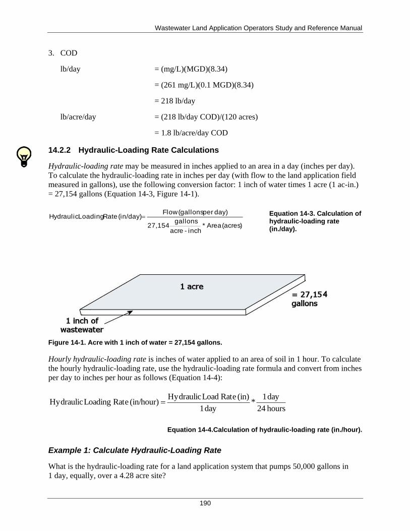
Wastewater Land Application Operators Study and Reference Manual
190
3. COD
lb/day = (mg/L)(MGD)(8.34)
= (261 mg/L)(0.1 MGD)(8.34)
= 218 lb/day
lb/acre/day = (218 lb/day COD)/(120 acres)
= 1.8 lb/acre/day COD
14.2.2 Hydraulic-Loading Rate Calculations
Hydraulic-loading rate may be measured in inches applied to an area in a day (inches per day).
To calculate the hydraulic-loading rate in inches per day (with flow to the land application field
measured in gallons), use the following conversion factor: 1 inch of water times 1 acre (1 ac-in.)
= 27,154 gallons (Equation 14-3, Figure 14-1).
(acres) Area*inch-acre
gallons 27,154
day) per (gallonsFlow (in/day) Rate LoadingHydraulic Equation 14-3. Calculation of
hydraulic-loading rate (in./day).
Figure 14-1. Acre with 1 inch of water = 27,154 gallons.
Hourly hydraulic-loading rate is inches of water applied to an area of soil in 1 hour. To calculate
the hourly hydraulic-loading rate, use the hydraulic-loading rate formula and convert from inches
per day to inches per hour as follows (Equation 14-4):
hours 24
day 1 *
day 1
(in) Rate Load Hydraulic (in/hour) Rate Loading Hydraulic
Equation 14-4.Calculation of hydraulic-loading rate (in./hour).
Example 1: Calculate Hydraulic-Loading Rate
What is the hydraulic-loading rate for a land application system that pumps 50,000 gallons in
1 day, equally, over a 4.28 acre site?
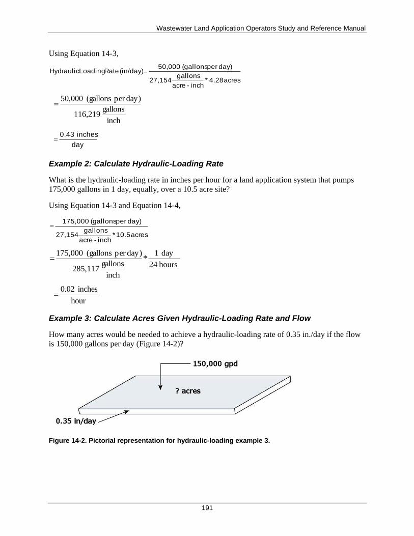
Wastewater Land Application Operators Study and Reference Manual
191
Using Equation 14-3,
acres 4.28 *inch-acre
gallons 27,154
day) per (gallons 50,000 (in/day) Rate LoadingHydraulic
inch
gallons 116,219
day)per (gallons 50,000
day
inches 0.43
Example 2: Calculate Hydraulic-Loading Rate
What is the hydraulic-loading rate in inches per hour for a land application system that pumps
175,000 gallons in 1 day, equally, over a 10.5 acre site?
Using Equation 14-3 and Equation 14-4,
acres 10.5 *inch-acre
gallons 27,154
day) per (gallons 175,000
hours 24
day 1*
inch
gallons 285,117
day)per (gallons 175,000
hour
inches 0.02
Example 3: Calculate Acres Given Hydraulic-Loading Rate and Flow
How many acres would be needed to achieve a hydraulic-loading rate of 0.35 in./day if the flow
is 150,000 gallons per day (Figure 14-2)?
Figure 14-2. Pictorial representation for hydraulic-loading example 3.
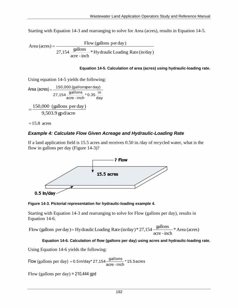
Wastewater Land Application Operators Study and Reference Manual
192
Starting with Equation 14-3 and rearranging to solve for Area (acres), results in Equation 14-5.
(in/day) Rate Loading Hydraulic *inch-acre
gallons 27,154
day)per (gallons Flow (acres) Area
Equation 14-5. Calculation of area (acres) using hydraulic-loading rate.
Using equation 14-5 yields the following:
Area (acres)
day
in 0.35 *
inch-acre
gallons 27,154
day) per (gallons 150,000
gpd/acre 9,503.9
day)per (gallons 150,000
acres 15.8
Example 4: Calculate Flow Given Acreage and Hydraulic-Loading Rate
If a land application field is 15.5 acres and receives 0.50 in./day of recycled water, what is the
flow in gallons per day (Figure 14-3)?
Figure 14-3. Pictorial representation for hydraulic-loading example 4.
Starting with Equation 14-3 and rearranging to solve for Flow (gallons per day), results in
Equation 14-6.
(acres) Area *inch-acre
gallons 27,154 * (in/day) Rate Loading Hydraulic day)per (gallons Flow
Equation 14-6. Calculation of flow (gallons per day) using acres and hydraulic-loading rate.
Using Equation 14-6 yields the following:
Flow (gallons per day) acres 15.5*inch-acre
gallons 27,154 *in/day 0.5
Flow (gallons per day) = 210,444 gpd
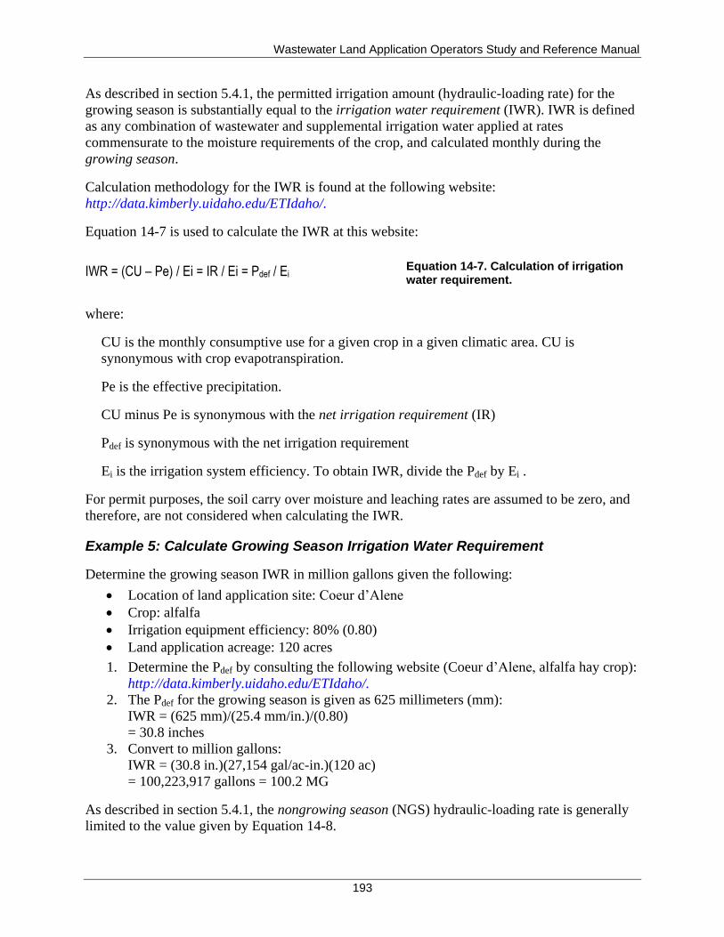
Wastewater Land Application Operators Study and Reference Manual
193
As described in section 5.4.1, the permitted irrigation amount (hydraulic-loading rate) for the
growing season is substantially equal to the irrigation water requirement (IWR). IWR is defined
as any combination of wastewater and supplemental irrigation water applied at rates
commensurate to the moisture requirements of the crop, and calculated monthly during the
growing season.
Calculation methodology for the IWR is found at the following website:
http://data.kimberly.uidaho.edu/ETIdaho/.
Equation 14-7 is used to calculate the IWR at this website:
IWR = (CU – Pe) / Ei = IR / Ei = Pdef / Ei Equation 14-7. Calculation of irrigation water requirement.
where:
CU is the monthly consumptive use for a given crop in a given climatic area. CU is
synonymous with crop evapotranspiration.
Pe is the effective precipitation.
CU minus Pe is synonymous with the net irrigation requirement (IR)
Pdef is synonymous with the net irrigation requirement
Ei is the irrigation system efficiency. To obtain IWR, divide the Pdef by Ei .
For permit purposes, the soil carry over moisture and leaching rates are assumed to be zero, and
therefore, are not considered when calculating the IWR.
Example 5: Calculate Growing Season Irrigation Water Requirement
Determine the growing season IWR in million gallons given the following:
Location of land application site: Coeur d’Alene
Crop: alfalfa
Irrigation equipment efficiency: 80% (0.80)
Land application acreage: 120 acres
1. Determine the Pdef by consulting the following website (Coeur d’Alene, alfalfa hay crop):
http://data.kimberly.uidaho.edu/ETIdaho/.
2. The Pdef for the growing season is given as 625 millimeters (mm):
IWR = (625 mm)/(25.4 mm/in.)/(0.80)
= 30.8 inches
3. Convert to million gallons:
IWR = (30.8 in.)(27,154 gal/ac-in.)(120 ac)
= 100,223,917 gallons = 100.2 MG
As described in section 5.4.1, the nongrowing season (NGS) hydraulic-loading rate is generally
limited to the value given by Equation 14-8.
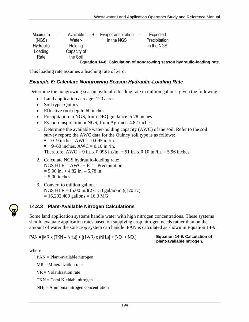
Wastewater Land Application Operators Study and Reference Manual
194
Maximum (NGS)
Hydraulic Loading
Rate
= Available Water-Holding
Capacity of the Soil
+ Evapotranspiration in the NGS
- Expected Precipitation in the NGS
Equation 14-8. Calculation of nongrowing season hydraulic-loading rate.
This loading rate assumes a leaching rate of zero.
Example 6: Calculate Nongrowing Season Hydraulic-Loading Rate
Determine the nongrowing season hydraulic-loading rate in million gallons, given the following:
Land application acreage: 120 acres
Soil type: Quincy
Effective root depth: 60 inches
Precipitation in NGS, from DEQ guidance: 5.78 inches
Evapotranspiration in NGS, from Agrimet: 4.82 inches
1. Determine the available water-holding capacity (AWC) of the soil. Refer to the soil
survey report; the AWC data for the Quincy soil type is as follows:
0–9 inches, AWC = 0.095 in./in.
9–60 inches, AWC = 0.10 in./in.
Therefore, AWC = 9 in. x 0.095 in./in. + 51 in. x 0.10 in./in. = 5.96 inches.
2. Calculate NGS hydraulic-loading rate:
NGS HLR = AWC + ET – Precipitation
= 5.96 in. + 4.82 in. – 5.78 in.
= 5.00 inches
3. Convert to million gallons:
NGS HLR = (5.00 in.)(27,154 gal/ac-in.)(120 ac)
= 16,292,400 gallons = 16.3 MG
14.2.3 Plant-Available Nitrogen Calculations
Some land application systems handle water with high nitrogen concentrations. These systems
should evaluate application rates based on supplying crop nitrogen needs rather than on the
amount of water the soil-crop system can handle. PAN is calculated as shown in Equation 14-9.
PAN = [MR x (TKN – NH3)] + [(1-VR) x (NH3)] + [NO3 + NO2] Equation 14-9. Calculation of plant-available nitrogen.
where:
PAN = Plant-available nitrogen
MR = Mineralization rate
VR = Volatilization rate
TKN = Total Kjeldahl nitrogen
NH3 = Ammonia nitrogen concentration
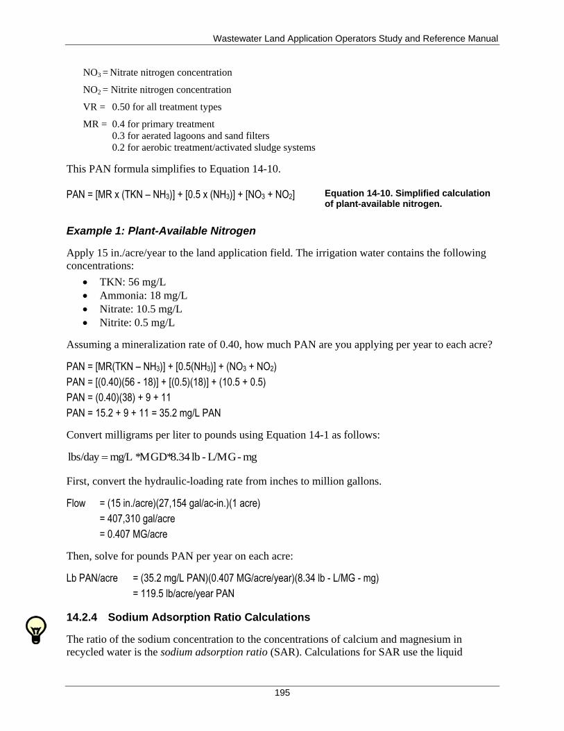
Wastewater Land Application Operators Study and Reference Manual
195
NO3 = Nitrate nitrogen concentration
NO2 = Nitrite nitrogen concentration
VR = 0.50 for all treatment types
MR = 0.4 for primary treatment
0.3 for aerated lagoons and sand filters
0.2 for aerobic treatment/activated sludge systems
This PAN formula simplifies to Equation 14-10.
PAN = [MR x (TKN – NH3)] + [0.5 x (NH3)] + [NO3 + NO2]
Equation 14-10. Simplified calculation of plant-available nitrogen.
Example 1: Plant-Available Nitrogen
Apply 15 in./acre/year to the land application field. The irrigation water contains the following
concentrations:
TKN: 56 mg/L
Ammonia: 18 mg/L
Nitrate: 10.5 mg/L
Nitrite: 0.5 mg/L
Assuming a mineralization rate of 0.40, how much PAN are you applying per year to each acre?
PAN = [MR(TKN – NH3)] + [0.5(NH3)] + (NO3 + NO2)
PAN = [(0.40)(56 - 18)] + [(0.5)(18)] + (10.5 + 0.5)
PAN = (0.40)(38) + 9 + 11
PAN = 15.2 + 9 + 11 = 35.2 mg/L PAN
Convert milligrams per liter to pounds using Equation 14-1 as follows:
mg-L/MG-lb 8.34* MGD* mg/L lbs/day
First, convert the hydraulic-loading rate from inches to million gallons.
Flow = (15 in./acre)(27,154 gal/ac-in.)(1 acre)
= 407,310 gal/acre
= 0.407 MG/acre
Then, solve for pounds PAN per year on each acre:
Lb PAN/acre = (35.2 mg/L PAN)(0.407 MG/acre/year)(8.34 lb - L/MG - mg)
= 119.5 lb/acre/year PAN
14.2.4 Sodium Adsorption Ratio Calculations
The ratio of the sodium concentration to the concentrations of calcium and magnesium in
recycled water is the sodium adsorption ratio (SAR). Calculations for SAR use the liquid
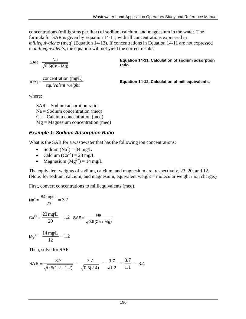
Wastewater Land Application Operators Study and Reference Manual
196
concentrations (milligrams per liter) of sodium, calcium, and magnesium in the water. The
formula for SAR is given by Equation 14-11, with all concentrations expressed in
milliequivalents (meq) (Equation 14-12). If concentrations in Equation 14-11 are not expressed
in milliequivalents, the equation will not yield the correct results:
Mg) 0.5(Ca
Na SAR
Equation 14-11. Calculation of sodium adsorption
ratio.
weightequivalent
(mg/L)ion concentrat meq Equation 14-12. Calculation of milliequivalents.
where:
SAR = Sodium adsorption ratio
Na = Sodium concentration (meq)
Ca = Calcium concentration (meq)
Mg = Magnesium concentration (meq)
Example 1: Sodium Adsorption Ratio
What is the SAR for a wastewater that has the following ion concentrations:
Sodium (Na+) = 84 mg/L
Calcium (Ca2+
) = 23 mg/L
Magnesium (Mg2+
) = 14 mg/L
The equivalent weights of sodium, calcium, and magnesium are, respectively, 23, 20, and 12.
(Note: for sodium, calcium, and magnesium, equivalent weight = molecular weight / ion charge.)
First, convert concentrations to milliequivalents (meq).
Na+
= 7.323
mg/L 84
Ca2+
= 2.120
mg/L 23
Mg) 0.5(Ca
Na SAR
Mg2+
= 2.112
mg/L 14
Then, solve for SAR
1.2) 0.5(1.2
3.7 SAR
=
0.5(2.4)
3.7 =
1.2
3.7 =
1.1
3.7 = 3.4
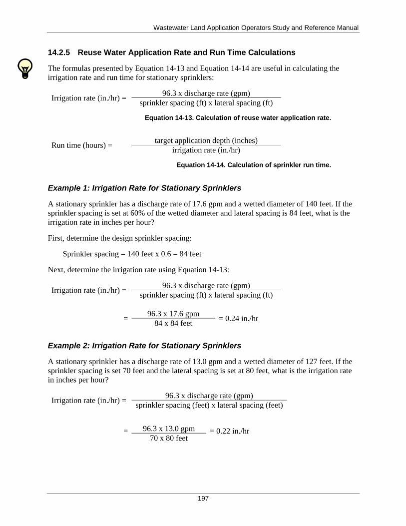
Wastewater Land Application Operators Study and Reference Manual
197
14.2.5 Reuse Water Application Rate and Run Time Calculations
The formulas presented by Equation 14-13 and Equation 14-14 are useful in calculating the
irrigation rate and run time for stationary sprinklers:
Irrigation rate (in./hr) = 96.3 x discharge rate (gpm)
sprinkler spacing (ft) x lateral spacing (ft)
Equation 14-13. Calculation of reuse water application rate.
Run time (hours) = target application depth (inches)
irrigation rate (in./hr)
Equation 14-14. Calculation of sprinkler run time.
Example 1: Irrigation Rate for Stationary Sprinklers
A stationary sprinkler has a discharge rate of 17.6 gpm and a wetted diameter of 140 feet. If the
sprinkler spacing is set at 60% of the wetted diameter and lateral spacing is 84 feet, what is the
irrigation rate in inches per hour?
First, determine the design sprinkler spacing:
Sprinkler spacing = 140 feet x 0.6 = 84 feet
Next, determine the irrigation rate using Equation 14-13:
Irrigation rate (in./hr) = 96.3 x discharge rate (gpm)
sprinkler spacing (ft) x lateral spacing (ft)
= 96.3 x 17.6 gpm
= 0.24 in./hr 84 x 84 feet
Example 2: Irrigation Rate for Stationary Sprinklers
A stationary sprinkler has a discharge rate of 13.0 gpm and a wetted diameter of 127 feet. If the
sprinkler spacing is set 70 feet and the lateral spacing is set at 80 feet, what is the irrigation rate
in inches per hour?
Irrigation rate (in./hr) = 96.3 x discharge rate (gpm)
sprinkler spacing (feet) x lateral spacing (feet)
= 96.3 x 13.0 gpm = 0.22 in./hr 70 x 80 feet
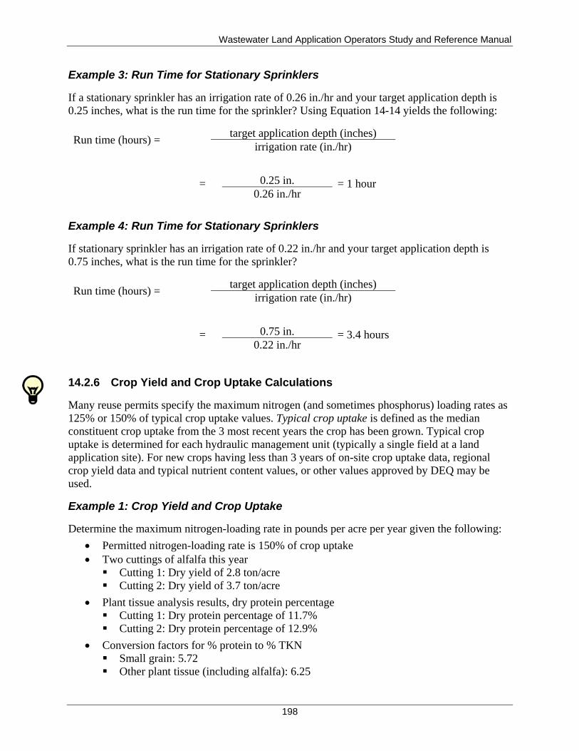
Wastewater Land Application Operators Study and Reference Manual
198
Example 3: Run Time for Stationary Sprinklers
If a stationary sprinkler has an irrigation rate of 0.26 in./hr and your target application depth is
0.25 inches, what is the run time for the sprinkler? Using Equation 14-14 yields the following:
Run time (hours) = target application depth (inches)
irrigation rate (in./hr)
=
0.25 in. = 1 hour 0.26 in./hr
Example 4: Run Time for Stationary Sprinklers
If stationary sprinkler has an irrigation rate of 0.22 in./hr and your target application depth is
0.75 inches, what is the run time for the sprinkler?
Run time (hours) = target application depth (inches)
irrigation rate (in./hr)
=
0.75 in. = 3.4 hours 0.22 in./hr
14.2.6 Crop Yield and Crop Uptake Calculations
Many reuse permits specify the maximum nitrogen (and sometimes phosphorus) loading rates as
125% or 150% of typical crop uptake values. Typical crop uptake is defined as the median
constituent crop uptake from the 3 most recent years the crop has been grown. Typical crop
uptake is determined for each hydraulic management unit (typically a single field at a land
application site). For new crops having less than 3 years of on-site crop uptake data, regional
crop yield data and typical nutrient content values, or other values approved by DEQ may be
used.
Example 1: Crop Yield and Crop Uptake
Determine the maximum nitrogen-loading rate in pounds per acre per year given the following:
Permitted nitrogen-loading rate is 150% of crop uptake
Two cuttings of alfalfa this year
Cutting 1: Dry yield of 2.8 ton/acre
Cutting 2: Dry yield of 3.7 ton/acre
Plant tissue analysis results, dry protein percentage
Cutting 1: Dry protein percentage of 11.7%
Cutting 2: Dry protein percentage of 12.9%
Conversion factors for % protein to % TKN
Small grain: 5.72
Other plant tissue (including alfalfa): 6.25
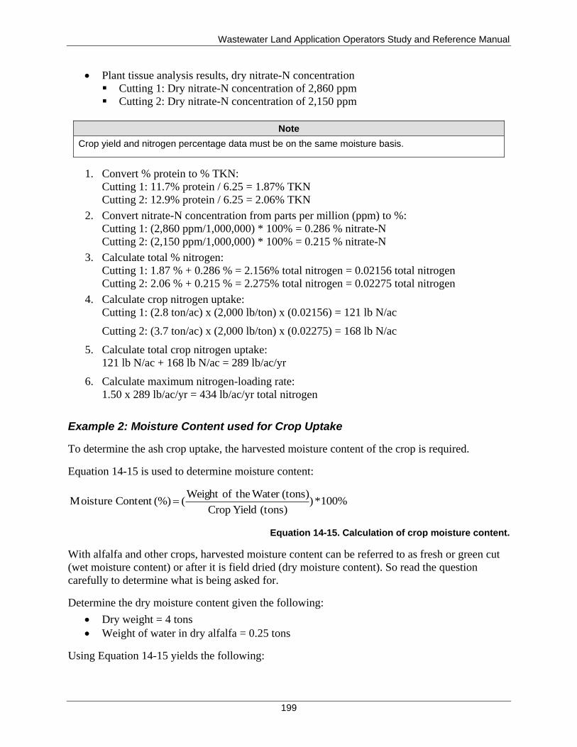
Wastewater Land Application Operators Study and Reference Manual
199
Plant tissue analysis results, dry nitrate-N concentration
Cutting 1: Dry nitrate-N concentration of 2,860 ppm
Cutting 2: Dry nitrate-N concentration of 2,150 ppm
Note
Crop yield and nitrogen percentage data must be on the same moisture basis.
1. Convert % protein to % TKN:
Cutting 1: 11.7% protein / 6.25 = 1.87% TKN
Cutting 2: 12.9% protein / 6.25 = 2.06% TKN
2. Convert nitrate-N concentration from parts per million (ppm) to %:
Cutting 1: (2,860 ppm/1,000,000) * 100% = 0.286 % nitrate-N
Cutting 2: (2,150 ppm/1,000,000) * 100% = 0.215 % nitrate-N
3. Calculate total % nitrogen:
Cutting 1: 1.87 % + 0.286 % = 2.156% total nitrogen = 0.02156 total nitrogen
Cutting 2: 2.06 % + 0.215 % = 2.275% total nitrogen = 0.02275 total nitrogen
4. Calculate crop nitrogen uptake:
Cutting 1: (2.8 ton/ac) x (2,000 lb/ton) x (0.02156) = 121 lb N/ac
Cutting 2: (3.7 ton/ac) x (2,000 lb/ton) x (0.02275) = 168 lb N/ac
5. Calculate total crop nitrogen uptake:
121 lb N/ac + 168 lb N/ac = 289 lb/ac/yr
6. Calculate maximum nitrogen-loading rate:
1.50 x 289 lb/ac/yr = 434 lb/ac/yr total nitrogen
Example 2: Moisture Content used for Crop Uptake
To determine the ash crop uptake, the harvested moisture content of the crop is required.
Equation 14-15 is used to determine moisture content:
%100*)(tons) Yield Crop
(tons) Water theofWeight ( (%)Content Moisture
Equation 14-15. Calculation of crop moisture content.
With alfalfa and other crops, harvested moisture content can be referred to as fresh or green cut
(wet moisture content) or after it is field dried (dry moisture content). So read the question
carefully to determine what is being asked for.
Determine the dry moisture content given the following:
Dry weight = 4 tons
Weight of water in dry alfalfa = 0.25 tons
Using Equation 14-15 yields the following:
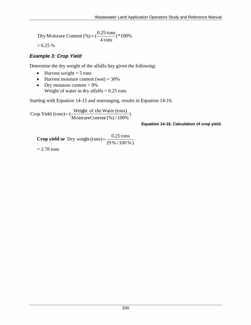
Wastewater Land Application Operators Study and Reference Manual
200
%100*) tons4
tons0.25( (%)Content MoistureDry
= 6.25 %
Example 3: Crop Yield
Determine the dry weight of the alfalfa hay given the following:
Harvest weight = 5 tons
Harvest moisture content (wet) = 30%
Dry moisture content = 9%
Weight of water in dry alfalfa = 0.25 tons
Starting with Equation 14-15 and rearranging, results in Equation 14-16.
)100% / (%)Content Moisture
(tons) Water theofWeight ( (tons) Yield Crop
Equation 14-16. Calculation of crop yield.
Crop yield or ) % 100 / % (9
tons0.25 (tons) Dry weight
= 2.78 tons
Wastewater Land Application Operators Study and Reference Manual
201
15 Health and Safety
Need-to-Know Criteria
Personal protective equipment
Health and safety hazards and measures
Lockout and tagout policy
Public health and safety
Accidents and injuries do not just happen; they are caused. Behind every accident is a chain of
events that leads up to an unsafe act, unsafe conditions, or a combination of both.
Communication between supervisors and employees generates ideas and safety awareness that
leads to accident prevention. Safety programs, manuals, and meetings are essential in providing
the lines of communication that lead to a safe, accident-free workplace. Some of the minimum
recommended safety tips are discussed below. Additional site-specific safety requirements
should be covered in the facility PO.
15.1 Regulatory Overview
A variety of federal and state laws and regulations exist to protect workers in both the private
and public sectors. At the federal level, the regulatory agency that oversees worker safety is the
United States Occupational Safety and Health Administration (OSHA). OSHA oversight does
not include state or local government employees. In Idaho, state and local government public
employee safety and health are overseen by the Idaho Division of Building Safety. These safety
standards are designed, at a minimum, to meet or exceed the OSHA standards.
15.1.1 Employer Responsibilities
The permittee is responsible for the following:
Provide a workplace that is free from recognized hazards that are causing or likely to
cause serious injury or death.
Furnish and require use of safety devices and safeguards, safe work practices and
procedures, and operations and processes that are adequate to ensure employees are safe
while performing their jobs.
Comply with all OSHA and/or state standards.
15.1.2 Site Supervisor Responsibilities
The site supervisor is responsible for the following:
Establish and supervise a Health and Safety Program that is designed to improve the
safety and health skills and competency of all employees.
Conduct preliminary investigations to determine the cause of any accident that results in
injury. The results of this investigation should be documented for reference.
Wastewater Land Application Operators Study and Reference Manual
202
Establish and maintain a system for maintaining records of occupational injuries and
illnesses.
Provide new employees with a safety orientation on the special hazards and precautions
of any new job.
Conduct job briefings with employees before starting any job, to acquaint employees
with any unfamiliar procedures.
Issue any needed safety equipment and manuals.
Conduct periodic group safety meetings.
15.1.3 Employee Responsibilities
Employees have the responsibility to do the following:
Comply with OSHA and/or state standards and rules that are applicable to their own
actions and conduct.
Keep informed of current safe work practices and procedures.
Be responsible for their own safety.
Request instruction from the site supervisor if there is a question as to the safe
performance of work assigned.
Use appropriate safety devices and wear suitable clothing and appropriate personal
protective equipment (PPE).
Report any unsafe conditions, practices, or procedures to the site supervisor
15.2 Health and Safety Program
As mentioned above, the site supervisor is responsible for developing a Health and Safety
Program. This program should include the following:
Procedures for reporting incidents, injuries, and unsafe conditions or practices
Instructions on identification and safe use of hazardous gases, chemicals and materials,
and emergency procedures following exposure
Use and care of PPE
15.2.1 Incident Reporting
As part of the Health and Safety Program, all facilities should develop a formal incident
reporting and investigation program. All incidents, including injuries, accidents, and near misses
should be reported to the site supervisor immediately, and these incidents should be investigated
as soon as possible to determine their root causes.
The information gained from an investigation should then be used to change work practices and
to eliminate hazardous activities. Injuries requiring treatment other than first aid treatment must
be reported on OSHA 200 form (Log and Summary of Injuries and Illnesses).
15.2.2 Hazard Communication Standard
The “Hazard Communication” standard (29 CFR 1910.1200), mandated by OSHA, is another
important component of any Health and Safety Plan. The goal of 29 CFR 1910.1200 is to reduce
Wastewater Land Application Operators Study and Reference Manual
203
injuries and illnesses resulting from improper use and storage of chemicals in the workplace.
Employers must inform or instruct employees about the following when chemicals that are used
in the workplace:
Safety and health standards for the safe use of chemicals
Known health hazards of the chemicals used in the workplace
Methods of hazard control
Proper labeling of containers
Maintaining current material safety data sheets on all chemicals
Chemical inventory
Emergency procedures versus nonemergency procedures
Training in recognizing, evaluating, and controlling hazards
15.2.3 Chemical Hygiene Plan
OSHA’s laboratory standard requirements are found in the “Occupational Exposure to
Hazardous Chemicals in Laboratories” (29 CFR 1910.1450). Facilities with a laboratory that
performs analytical tests may need to develop a chemical hygiene plan. A chemical hygiene plan
includes instruction on the following topics:
How laboratory personnel handle and work with hazardous laboratory chemicals
How employee exposure to these chemicals will be minimized
What PPE will be used in the laboratory
Specifications for working with particularly hazardous substances, such as cancer-
causing chemicals, and other requirements.
The chemical hygiene plan must be a written plan and must be evaluated on a regular basis for
effectiveness.
15.2.4 Personal Protective Equipment
Another important component of a Health and Safety Program is a written program covering the
appropriate selection, use, and maintenance of PPE. The proper selection and use of PPE is one
of the most effective methods for preventing occupational injuries and illnesses. Types of PPE
include the following:
Head protection
Eye and face protection
Hearing protection
Foot and leg protection
Body protection
Respiratory protection
15.2.4.1 Head Protection
Any head injury has the potential to be serious. Any injury that results in brain damage can cause
memory loss, affect the ability to reason, and cause changes in personality and emotions. Any of
these changes can result in disability and interfere with the ability to earn a living. Fortunately, a
Wastewater Land Application Operators Study and Reference Manual
204
variety of PPE is suitable for the activities normally associated with wastewater treatment
facilities:
Bump caps are lightweight plastic caps designed to protect the head from bumps and scrapes
encountered in tasks such as building and machinery maintenance. A bump cap will not provide
protection from impact, such as a dropped tool or other heavy object, but bump caps are
recommended for tasks where cleanliness and sanitation are high priorities, such as in food
processing plants or when handling pesticides. A bump cap or hard hat can be decontaminated
with soap and water, but a baseball cap or cowboy hat cannot be completely decontaminated of
chemicals.
Safety helmets (hard hats) are primarily intended to protect the head from falling objects,
although they can also provide protection from flying objects. A hard hat consists of a sturdy
shell, usually made of plastic, and a suspension that holds the shell at least 1-1/4 inches from the
head. When an object strikes the hat, the force is distributed through the suspension to a large
area of the head and neck, preventing puncture wounds and concussion injuries in most cases.
Hard hats are recommended for all construction and timber harvesting activities and any other
tasks involving the risk of bumps or falling objects. While a hard hat may not be able to protect a
person from a severe, direct blow, it can deflect many glancing blows that might otherwise result
in serious injury or death.
Accessories that can be mounted on a hard hat include welding helmets, face shields, hearing
protectors, and communications devices. These devices are useful because several PPE items
needed for a particular task can be kept together. For example, a hard hat with a face screen and
hearing protectors is ideal for chain saw operation.
Although hard hats are heavier than baseball caps, they are cooler than baseball caps because
there is an air space between the head and shell. This coolness is welcomed in summer, but a
liner is often needed in winter to maintain comfort.
Accidents, abuse, or improper care can damage any type of protective headgear. Remember these
points:
Always replace any protective headgear that has received a hard blow because it may
have sustained damage that is not visible.
Never wash any protective headgear with anything stronger than mild detergent and
water. Solvents can weaken or destroy the plastics used for protective headgear.
Note
Use safety helmets that comply with the American National Standards Institute Z89.1 criteria. Never use a metal hard hat when working around electrical systems.
15.2.4.2 Eye and Face Protection
Our eyes are one of the most vulnerable parts of our bodies. Chemical burns, flying particles,
cuts, heat, light, and blows to the head or face cause eye injuries. Eye and face protective devices
include face shields, safety glasses, and goggles.
Wastewater Land Application Operators Study and Reference Manual
205
Safety glasses are available in a wide variety of styles and can be equipped with or without side
shields. Lenses can be made of plastic or heat treated/chemically treated glass. Metal frames
should not be worn in an electrical hazard area.
Goggles can be worn over regular prescription eyewear. Goggle frames are made of molded
synthetic rubber, natural rubber or vinyl, and lenses are made of plastic, acetate, or glass.
Goggles with ventilation should be used where fogging is a problem. In areas where dust, smoke,
aerosols, chemical splashes, or fumes can irritate eyes, goggles without ventilation should be
used.
Face shields provide additional protection for eyes and should only be worn over primary eye
protection. The shields also provide protection for the nose, mouth, and throat. Face shields are
generally made of plastic but are available in reflecting metal screen where radiant heat is a
problem. Face shields can be attached directly to a hard hat.
15.2.4.3 Hearing Protection
Noise is a fact of life; however, noise above a certain level can be harmful and cause permanent
hearing damage. Noise can come from a variety of sources, such as gasoline or diesel engines,
gas or electric blowers, mechanical equipment, spreaders, and other types of machinery.
Each employer is required to determine if noise above what is called the action level exists in the
workplace. If so, actions must be taken to reduce the noise level and protect the employees. The
employer is required to develop a hearing conservation program, which is designed to
effectively limit employee exposure to harmful levels of noise.
OSHA’s standard on “Occupational Noise Exposure” (29 CFR 1910.95) stipulates what a
minimum level hearing conservation program must contain and provides guidance for employers
to develop their own effective program. The hearing conservation program states that employees
must wear proper ear-protecting devices whenever they are working in a noise hazard area.
Hearing protection devices include earplugs, earmuffs, and semiaurals or canal caps.
15.2.4.4 Hand and Arm Protection
One of the best methods of protecting the hands (and preventing dermatitis elsewhere) is to
thoroughly wash the hands with soap and water and dry them with single-use towels when
finishing a task, before eating, and after using the restroom.
Gloves also provide hand and arm protection, and they are available in a wide variety of styles
and materials, each having its advantages and disadvantages. Since there is no single type of
glove that is suitable for all tasks, it is important to understand a few basics of selecting gloves.
When determining the types of gloves to use, ask the following questions:
Do you need protection from cuts and scrapes, protection from heat, or protection from
chemicals?
Are the hazards low, moderate, or high?
Do you need to wear gloves all day or intermittently?
Do you need good manual dexterity for handling controls, tools, or small objects?
Wastewater Land Application Operators Study and Reference Manual
206
Glove selection becomes complicated when a situation involves several hazards or types of tasks.
Chemical labels are required to give specific recommendations for PPE, including gloves. The
PPE stated on the chemical label must be used to comply with federal and state regulations.
Check the label for PPE recommendations, or refer to a chemical resistance chart (featured in
safety product catalogs), and select a material that provides good to excellent resistance from the
chemicals you will be exposed to. Never use leather or fabric gloves when handling toxic
chemicals—chemicals readily penetrate these materials, and they can never be fully
decontaminated.
Gloves are made from many materials. Three to four types of gloves may be needed. The choices
will depend on the specific needs for protection from chemical and physical hazards.
Fabric (e.g., jersey, cotton flannel, and knit) gloves are inexpensive and suitable for many tasks
where protection is needed from minor cuts and scrapes. Cloth gloves are also ideal for tasks
where protection is needed from friction or when a glove might aid in gripping objects. Gloves
with dimples or rubberized fabric on the palms and fingers are excellent when using hand tools
and other similar tasks.
Some fabrics are also used for high temperature applications, such as welding. Cloth gloves may
be more flexible than leather welding gloves but can result in serious burns if they are wet when
a hot object is picked up—unless they have a moisture barrier. A significant advantage of cloth
gloves is that they breathe well, minimizing perspiration buildup.
Leather is possibly the best all-around choice for protection from cuts, scrapes, friction, and
other physical hazards. Leather is tough, flexible, inexpensive, and it breathes well. Leather can
be sewn into a wide variety of gloves, and it may be used in conjunction with other materials for
specialized purposes. For example, Kevlar (the material used in body armor for police officers) is
used in gloves for chain saw operators to provide extra protection from cuts should the left hand
come in contact with the moving chain. Another example is the insulating materials sewn inside
gloves used by welders to protect them from burns.
Rubber gloves are needed for protection from the wide variety of chemicals that may be used at a
spray irrigation site. However, several rubber materials are used for gloves today, and it is
important that the correct material be used. Using the wrong material can allow chemicals to
penetrate through the gloves or cause the gloves to deteriorate. Always refer to the
manufacturer’s chemical resistance chart and glove selection guidelines when selecting rubber
gloves.
Cut-resistant materials such as Kevlar, steel-reinforced fabrics, and chain link mesh are used in
gloves designed for tasks where cuts are a major risk, such as handling glass and other sharp
objects. Although these materials can be cut, they offer superior protection while permitting the
user to grasp tools and other objects. Cut-resistant gloves often feature slip-resistant materials or
textures on the fingers and palm to minimize the risk of sharp objects slipping through the hands,
thus reducing the risks of a cut.
Whatever type of gloves are chosen, remember these points:
Wastewater Land Application Operators Study and Reference Manual
207
Gloves should be thick enough to provide adequate chemical resistance and prevent
punctures or tears, yet thin enough to provide a good grip and manual dexterity.
Examination gloves (like doctors use) are not adequate for protection from most
chemicals, especially pesticides.
Unlined gloves are normally recommended when using chemicals since they can be
easily washed and decontaminated. Flock-lined gloves are more comfortable, however,
and often cost less than unlined gloves. Any lined gloves should be disposed of if
contaminated inside by chemicals.
The color of the gloves will affect comfort, especially outdoors. Black gloves will absorb
heat from the sunlight, making them uncomfortable, so select a lighter color for outdoor
work.
Cut, length, and thickness affect the comfort and performance of any glove. Some gloves
may be so heavily constructed that they will last forever, but are too stiff or otherwise
uncomfortable to be used on a routine basis. Gloves that are too heavy or uncomfortable,
or which do not fit well, can significantly reduce a worker’s productivity by making it
difficult to handle tools and other objects. Those gloves can also be dangerous in certain
situations. Other gloves may be very comfortable, but not durable enough to provide
satisfactory performance and economy. The ideal glove fits well, provides the needed
protection, permits good productivity, and is economical. If there are several workers, it
is likely that several styles or sizes of gloves will be needed. Try several styles of gloves
to determine which provides the best comfort, grip, and dexterity needed for the intended
tasks.
15.2.4.5 Foot and Leg Protection
Injuries to the feet are uncomfortable at best, and they can seriously interfere with the ability to
accomplish work activities. Although most foot injuries are not serious, they do result in pain
and lost production. Injuries resulting from dropped objects, punctures, and strains or sprains due
to slips and falls are probably the most common. Most of these can be prevented through a
combination of safe work practices and use of proper footwear. While high-top steel-toe boots
with steel shank and lug soles are not always needed, you probably should wear them some of
the time. Sneakers and smooth soled shoes are not good because they do not provide protection
from commonly encountered hazards.
Perhaps the most important aspect of good footwear is a nonslip sole. Good traction is needed to
prevent slips and falls while walking on various surfaces, and especially when climbing ladders
and stairs. Smooth leather soles common on western boots and dress shoes may be too slippery
on many surfaces. Soles with lugs or texture may provide better traction, especially when made
of the soft, yet long wearing materials found in quality boots. A steel shank can provide
improved puncture resistance as well as improved support in activities that place concentrated
loads on the feet, such as prolonged work on ladders or repeatedly pressing machinery brake
pedals.
Steel toe safety shoes protect the toes from injuries caused by dropped objects. While steel
toecaps are very effective in preventing injuries to the toes, they will not protect the rest of the
foot. Like any shoes or boots, safety shoes will not be comfortable unless they fit properly. Most
reputable safety shoe dealers can fit all sizes and widths from AAAA to EEE. If they fit properly,
Wastewater Land Application Operators Study and Reference Manual
208
the steel toe cap will only be noticed if it prevents an injury, when you are squatting, or
otherwise have your toes bent far back, or if you kick something and push your toes against the
toe cap.
Safety shoes are available in a wide variety of styles, including dress shoes and western boots, as
well as leather and rubber work boot styles. Some special purpose boots are available that
incorporate instep guards to prevent injuries behind the toes, Kevlar pads to prevent cuts from
chain saws, and caulks (screw-in spikes) to prevent slips when working on logs or ice.
Rubber boots are recommended for tasks involving prolonged contact with water or whenever a
risk of exposure to hazardous chemicals exists, such as pesticides. Just as when selecting rubber
gloves, ensure the material is suitable for the exposure. To prevent water and chemicals from
entering the top of the boot, place the coveralls outside the boot to shed water onto the ground.
A consideration that is often overlooked when using rubber boots is perspiration removal.
Because rubber boots do not breathe, perspiration cannot readily escape, so the socks and feet
will eventually be soaked with perspiration. Keeping the feet dry is essential for good health, so
proper measures must be taken. Socks of polypropylene and cotton blends can help wick the
moisture away, and moisture absorbent liners are available as well. Remove the boots and allow
the feet to breathe and dry occasionally. To help prevent foot health problems always wash and
dry the feet at the end of each day, allow footwear to dry and air out between uses, and begin
each day with clean, dry socks.
15.2.4.6 Body Protection
The skin is your body’s largest organ, and it performs a number of vital functions: keeping
moisture in; sweating to cool your body; and keeping harmful agents from entering the body.
Because the skin is exposed to so many hazards, it is important to protect it. The skin can
adequately protect the body from many hazards (such as most bacteria), however, it can easily be
penetrated or damaged by many chemicals. Another alarming fact is the increased incidence of
skin cancers resulting from sun exposure. People who spend long hours in the sun are at
increased risk of developing skin cancer unless they take protective measures.
Friction scrapes and cuts are also common sources of skin injuries and irritation. Properly
selected clothing can prevent or minimize the chances of many skin disorders. Normal clothing
can prevent many types of skin problems. For example, a light-colored long-sleeve shirt can
protect the arms and upper body from sunburn and reduce the risks of skin cancers, and the long-
sleeve shirt may actually be cooler than a short-sleeve shirt when working in the sun because it
will reflect the sunlight. Other clothing that helps prevent sunburn and skin cancer includes a
wide-brimmed hat to protect the ears, face, and neck, and long pants to protect the legs.
Coveralls should be made of a tightly woven fabric, such as cotton or polyester or of a nonwoven
fabric. They should fit loosely. Unless there is a layer of air between the coverall and the skin,
any chemical that gets through the coverall will be in direct contact with the skin. Each layer of
clothing worn under the coverall adds not only a layer of material, but also a protective layer of
air. Well-designed coveralls have tightly constructed seams and snug, overlapping closures that
do not gap or become easily unfastened.

Wastewater Land Application Operators Study and Reference Manual
209
Rubber or chemical-resistant aprons are needed when handling liquids for prolonged periods of
time, or when handling concentrated chemicals. Wear an apron even if other protective clothing
is also being worn. Keeping the skin clean and dry is always important, but the groin area is
especially sensitive. Chemicals can penetrate the skin of the groin area more than 11 times more
readily than through the forearm (Figure 15-1). A splash of a concentrated chemical here could
result in a high dose of toxins entering the body very quickly.
Choose an apron that extends from the neck to at least the knees. Some aprons have attached
sleeves, which can also protect the arms. Be aware that an apron can be a safety hazard in some
situations. It can get in the way or get caught in machinery. In these situations, consider wearing
a chemical-resistant suit instead.
Figure 15-1. Absorption rates of chemicals through the skin of various parts of the body. Numbers are rates of absorption in comparison to the forearm.
Chemical-resistant suits are often disposable and are made from a variety of materials that
provide varying levels of protection and comfort. They may be one-piece coveralls or two-piece
outfits consisting of a jacket worn over overalls or pants. Chemical-resistant suits can be
uncomfortably warm to wear. Take precautions to avoid overheating and heat stress. These
garments should be disposed of when damaged or contaminated, especially if contaminated with
concentrated chemicals.
15.2.4.7 Respiratory Protection
Warning
Use only respirators approved by the National Institute for Occupational Safety and Health or the Mine Safety and Health Administration for the hazards present in the workplace.
WWLA operators may be exposed to many irritating and potentially harmful airborne
contaminants while working at a land application facility. Examples of air contaminants include
particles of pollen, bacteria, mold spores, aerosols, hazardous chemicals, and engine exhausts.
The respiratory system is one of the easiest ways contaminants can enter our bodies.
Scalp 3.7
Ear Canal 5.4
Abdomen 2.1
Feet 1.6
Forehead 4.2
Forearm 1.0
Palm 1.3
Groin 11.8
Wastewater Land Application Operators Study and Reference Manual
210
One problem with occupational illnesses is that the worker may not associate the illness with
job-related exposures. Symptoms of respiratory illness may be mistaken for the flu, common
cold, or simple exhaustion.
Another problem is that people may perform a particular task for years without experiencing
adverse health effects, but suddenly experience a severe reaction to even slight exposures to
contaminants. The body can become sensitized and no longer tolerate even small exposures to a
substance. Additionally, some exposures can lead to permanent lung injury and disability.
Selecting and using a respirator involves more than simply purchasing one and putting it on.
Using the wrong respirator, or using a respirator improperly, can result in serious illness or death.
The respirator must be selected for the specific contaminants in your workplace, and it must fit
properly. In addition, the respirator must be properly cleaned, inspected, and stored after each
use to prolong its life and help ensure protection for later uses.
The best way to select a respirator is to consult an industrial hygienist or other similarly qualified
professional. If respirators are needed, these professionals can assist with selection, fit testing,
and training to use the respirator properly. Additionally, a written respiratory protection program
must be developed that specifies how these tasks will be accomplished.
Two basic types of respirators are air-purifying respirators and air-supplying respirators.
Air-purifying respirators remove contaminants from the air by filtering dust, mists, and
particles or by removing gases and vapors. These respirators will not protect the WWLA
operator from fumigants, from high concentrations of vapor, or when the oxygen supply
is low. Several styles of air-purifying respirators are described below:
Cup-style respirators filter out dust, mists, powders, and particles. They are usually
shaped filters that cover the nose and mouth.
Cartridge respirators are half-mask or full-face respirators that have chemical
cartridges containing air-purifying materials. Many chemical cartridge respirators can
be fitted with particulate prefilters. By using the proper cartridges and prefilters, it is
possible to use chemical cartridge respirators in a variety of situations. Chemical
cartridges are color-coded, so you can determine at a glance whether the correct
respirator is in use. The cartridge needed depends on the particular contaminants
present since different filter materials must be used for the various chemical hazards.
Canister respirators (gas masks) are full-face respirators with attached canisters
containing air-purifying materials. Canisters usually contain more air-purifying
materials than cartridge respirators. The face-piece is designed to be cleaned and
reused. Canisters can be replaced.
Air-purifying respirators pass air through the air-purifying material in two ways.
Negative-pressure respirators depend on the wearer’s lungpower to draw air through the
purifying material. Powered air-purifying respirators (PAPRs) assist the wearer by
forcing air through mechanically. PAPRs purify contaminated air as it passes through the
filter; they do not supply oxygen.
Air-supplying respirators supply clean, uncontaminated air from an independent source.
These respirators provide oxygen, and they can be used in oxygen deficient atmospheres,
or atmospheres that are immediately dangerous to life or health.
Wastewater Land Application Operators Study and Reference Manual
211
Two types of air-supplying respirators are the supplied-air respirator and the self-
contained breathing apparatus (SCBA).
A supplied-air respirator provides breathing quality air from an approved air pump
located in a safe atmosphere or from a remote tank of breathing air.
SCBA supplies clean air from cylinders that are carried with the WWLA operator,
usually on the back.
Air-supplied respirators must be inspected and tested regularly and should only be used
by specially trained individuals; use by untrained persons could lead to serious injury or
death.
15.3 Health and Safety Hazards
The WWLA operator may be exposed to numerous common hazards:
Physical injuries (most common hazard)
Infections and infectious diseases
Oxygen deficiency
Toxic or suffocating gases or vapors
Chemical contamination
Explosive gas mixtures
Fire (least common hazard)
Electrical shock
Noise-induced hearing loss
Dust, fumes, and mists
Heat exhaustion and heat stroke
15.3.1 Health and Safety Measures
Numerous safety practices, training, and equipment serve as preventative measures and allow the
WWLA operator to minimize the risk of the health and safety hazards listed in section 15.3:
Process safety management and risk management programs
Confined space safety
General site safety
Lockout/tagout policies
Electrical safety
Mechanical safety
Vehicle safety
Lagoon safety
Fire prevention and protection
Excavation and shoring safety
Medical safety
15.3.2 OSHA Process Safety Management and EPA Risk Management Programs
The OSHA Process Safety Management and EPA Risk Management programs regulate how
certain highly hazardous chemicals are to be used, stored, or manufactured. The goal of both
Wastewater Land Application Operators Study and Reference Manual
212
programs is to prevent accidental releases of the substances that can cause serious harm to the
public and environment. If you store or have on site at any one time more than a threshold
quantity of the chemicals listed in Table 15-1, then a process safety program and/or a risk
management program may be needed. EPA and OSHA have slightly different listings and
slightly different threshold quantities, and exemption from one program does not necessarily
mean exemption from the other. Generally, if a facility uses the chemicals in the amounts listed
in Table 15-1, the facility will need to develop a program. Specific information on the OSHA
program can be found in “Process Safety Management of Highly Hazardous Chemicals” (29
CFR 1910.119), and specific information on the EPA program can be found in “Chemical
Accident Prevention” (40 CFR 68).
Table 15-1. Threshold quantities for chemicals requiring a process safety program or risk management program.
Chemical EPA Threshold Quantity (lb) OSHA Threshold Quantity (lb)
Chlorine 2,500 1,500
Anhydrous ammonia 10,000 10,000
Aqueous ammonia > 20% 20,000 > 44% 15,000
Anhydrous sulfur dioxide 5,000 1,000 (liquid)
Methane 10,000 10,000
Propane 10,000 10,000
Notes: United States Environmental Protection Agency (EPA); Occupational Safety and Health Administration (OSHA); pound (lb)
15.4 Confined Space Safety
Two types of confined spaces are defined as follows:
1. A confined space has limited means of access (entry) and egress (exit), has an adequate
size and configuration for employee entry, and is not designed for continuous worker
occupancy.
2. A permit-required confined space requires a permit for entry, may have a potentially
hazardous atmosphere, may have an engulfment hazard, may have an entrapment hazard,
or may contain any other recognized hazard.
If a facility has permit-required confined spaces, a written confined space entry program must be
developed and implemented to be in compliance with OSHA regulations. Enclosed facilities
such as tanks and/or tanker trucks, would fall under the permit-required confined space
regulations.
Warning
Do not enter a permit-required confined space without proper training, equipment, and support personnel. Confined space regulations are found in “The Control of Hazardous Energy (Lockout/Tagout)” (29 CFR 1910.147).
The atmosphere of a confined space may be extremely hazardous because of the lack of natural
ventilation. This can result in the following dangerous situations:
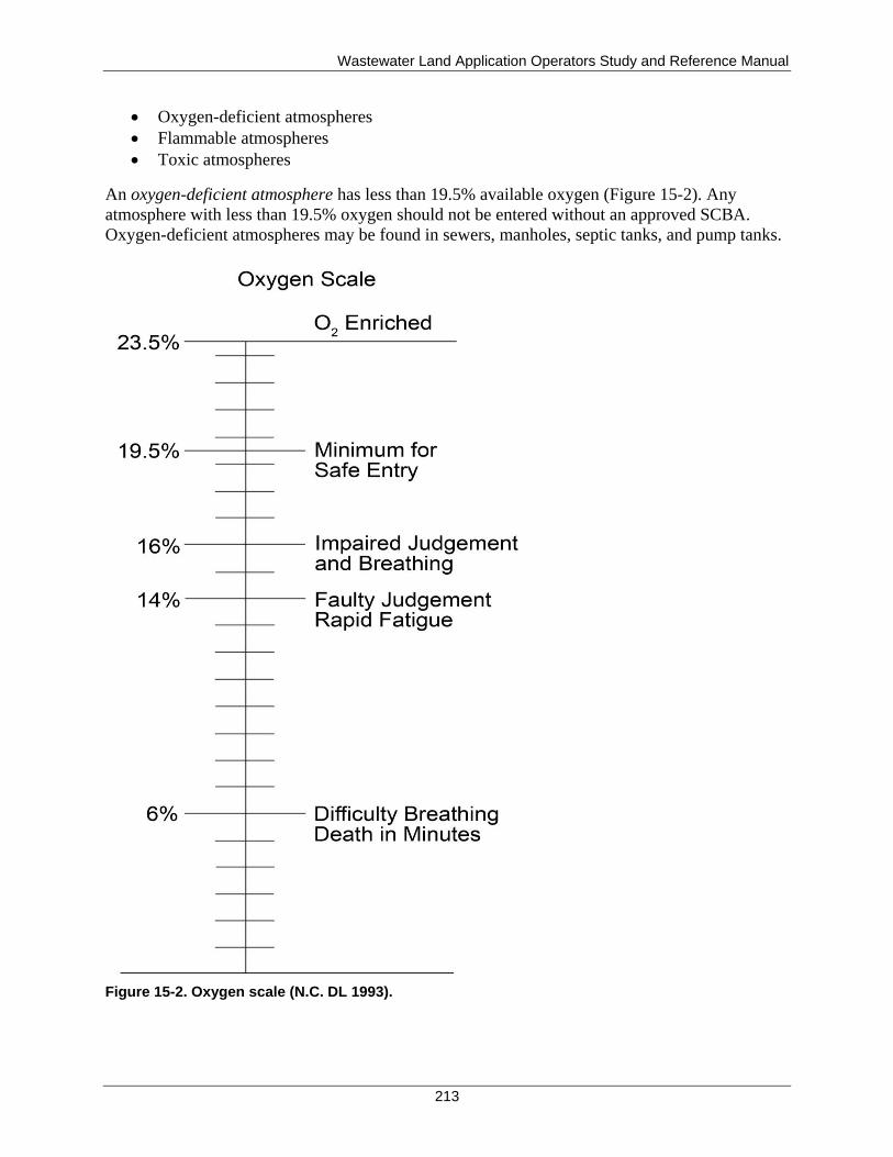
Wastewater Land Application Operators Study and Reference Manual
213
Oxygen-deficient atmospheres
Flammable atmospheres
Toxic atmospheres
An oxygen-deficient atmosphere has less than 19.5% available oxygen (Figure 15-2). Any
atmosphere with less than 19.5% oxygen should not be entered without an approved SCBA.
Oxygen-deficient atmospheres may be found in sewers, manholes, septic tanks, and pump tanks.
Figure 15-2. Oxygen scale (N.C. DL 1993).
Wastewater Land Application Operators Study and Reference Manual
214
When working in a confined space that does not require a permit, the following safety actions
must be taken:
Use a ladder, hoist, or other device when accessing these work areas.
Verify that the confined space is clean and well ventilated. Test the atmosphere of the
space, from the top of the work space to the bottom, for flammable/toxic gases and
oxygen deficiencies prior to entering the work space, and repeat testing during the work
period.
Use lifelines and always assign a standby person to remain on the outside of the confined
space. It is the standby person's responsibility to be in constant contact (visually and/or
verbally) with the workers inside the confined space as long as anyone is in the space.
Wear ear protection, as needed. Noise within a confined space can be amplified because
of the design and acoustic properties of the space.
Be mindful of the possibility of falling objects when working in confined spaces.
SCBA should be used in confined spaces where oxygen is insufficient.
15.5 General Site Safety
A land application site should be restricted to authorized personnel. This restriction is necessary
to prevent mishaps involving the public and to ensure that the site and all equipment are
protected from vandalism and theft.
Maintaining the land application site promotes a safe, well-kept working environment. Site
maintenance includes the following:
Keep walks, aisles, and access ways clear of tools and materials. Maintain clear access to
electrical panels, control valves, and fire extinguishers.
Clean up puddles of oil, sludge, or fuel promptly and thoroughly. Use absorbent material
if necessary.
Dispose of dirty and oily rags, used absorbent materials, trash, and other waste materials
in approved containers. The waste should be removed from the site and disposed of
properly.
Provide scrap containers or scrap collection area where needed.
Keep the sanitary facilities clean.
Keep supply areas organized and free of hazards.
Provide adequate illumination and ventilation.
15.5.1 Lockout/Tagout Policy
A lockout is a padlock placed on a power source to block the release of hazardous energy that
could set a machine in motion or otherwise endanger an employee working on the machine.
Locks are usually used with a lockout device that holds an energy control point, such as a switch
lever or valve handle in the off position, preventing machines or equipment from being operated
while the machine is being worked on.
A tagout is a written warning that tells other workers not to operate a switch or valve that could
release hazardous energy or set a machine in motion. Lockout is preferred because it is a more
Wastewater Land Application Operators Study and Reference Manual
215
secure method of controlling and isolating hazardous energy sources. Although lockout/tagout
policies most commonly refer to electrical energy, the following types should also be covered:
Mechanical
Hydraulic
Pneumatic
Stored
Chemical
Thermal
A written lockout/tagout program should be developed that specifies how individual machines or
equipment will be taken out of and returned to service. Once the program has been developed, all
employees who use or perform maintenance on any of the affected equipment must be properly
trained. Lockout/tagout procedures are frequently used measures to minimize hazards at a land
application facility.
15.5.2 Electrical Safety
Treat all electricity and electric power equipment with caution: ordinary 120 volt (V) electricity
can be fatal. Most systems operate from 120 V to 4,000 V, or more.
In case of electrocution, turn off power to the electrical source or use an insulated implement,
such as a piece of wood to separate the person from the source. Do not attempt to pull a victim
away from the electrical source with your bare hands. The following is a list of general electrical
safety practices (WEF 1996):
Allow only qualified and authorized personnel to work on electrical equipment and
wiring or to perform electrical maintenance.
Provide and use lockout devices and tags at all locations.
Always assume electrical equipment and lines are energized unless they are positively
proven to be de-energized and properly grounded. If the equipment is not grounded, it is
not dead.
Prohibit use of metal ladders or metal tape measures around electrical equipment.
Ensure that two people always work as a team on energized equipment.
Use approved rubber gloves on voltages more than 300 V.
Do not open an energized electrical control panel.
Before work is done on a line or bus that operates at 440 V or higher, ensure it is de-
energized, locked out, and grounded in an approved manner.
Do not test a circuit with any part of the body.
Prevent grounding by avoiding body contact with water, pipes, drains, or metal objects
while working on electrical equipment or wiring.
Do not bypass or render inoperative any electrical safety devices.
When working in close quarters, cover all energized circuits with approved insulating
blankets.
Use only tools that have insulated handles.
Never use metal-cased flashlights.
Do not wear jewelry when working with or near electric circuitry.
Ground or double-insulate all electrical tools.
Wastewater Land Application Operators Study and Reference Manual
216
Use rubber mats at control centers and electrical panels.
Always keep electric motors, switches, and control boxes clean.
15.5.3 Mechanical Safety
Mechanical safety guidelines apply to land application equipment, pressure-vacuum equipment,
and hydraulic systems.
15.5.3.1 Land Application Equipment
Keep the following in mind when working on land application equipment:
Ensure that sprinklers, guns, hydrants, valves, and plugs are not pressurized or
electrically energized when servicing or repairing land application equipment.
Pressurized or energized equipment can cause serious injury or death.
When servicing, turn pumps off and depressurize lines by opening drain valves or
opening discharge points to relieve water pressure.
If you must clean a nozzle, operate an isolation valve and clean the nozzle when not
under pressure.
Use the proper tools when working in valve boxes.
Valve boxes can be pinch points and are favorite havens of spiders and snakes, so be
alert!
Equipment such as traveling guns and center pivots (tractors) have many pinch points and
moving parts and are energized with high voltage electricity. Keep equipment guards in
place, tie back long hair, and do not wear loose clothing when operating this type of
equipment. Use lockout/tagout procedures when working on this equipment.
Be familiar with operational parameters from manufacturers’ literature.
Have a qualified electrician install and service all electrical systems for this type of
equipment.
Operating traveling guns (or hard-hose travelers) on steep and complex terrain can
present safety concerns. Slopes up to 15% (and possibly slightly higher) can be
effectively managed with traveling guns. However, the guns should be traversed across
the slopes in an up and down fashion as opposed to pulling the gun sideways across the
slope. If the gun is pulled sideways across the slope, the potential for a flipped gun cart
with the associated tractor and operator is much greater. Should a gun cart flip, the
system continues to apply recycled water from whatever position the sprinkler gun is in,
creating a safety hazard.
Gun carts typically have an adjustment that allows the wheel or track width to be
increased. The widest footprint possible should be used on sloping terrain.
Side slopes above 8% should be avoided if a sideways pull must be used.
Travel lanes for gun carts should be inspected for steeply sloping areas, gullies, tree
roots, rocks, or any other disturbances in a field. These disturbances can potentially cause
the gun cart to come off track or flip over. Correct these situations or select another travel
lane to use the field safely.
Machine guarding: Any machine part, function, or process that may cause injury must be
safeguarded. Safeguards are needed in the following locations:
Wastewater Land Application Operators Study and Reference Manual
217
At the point of operation, where the machine contacts the material and performs
operations, such as cutting, punching, grinding, boring, forming, or assembling.
Near power transmission components such as pulleys, belts, connecting rods, cams,
chains, sprockets, cranks, and gears
At other parts of the machine that move (rotation, reciprocating movement, transverse
movement) while the machine is working.
Operate machinery only if trained and authorized to use it.
Do not wear jewelry on the job.
While gloves are recommended for many tasks, do not wear them in situations where
they could get caught and draw you into a machine.
Do not try to adjust or reposition material while a machine is running.
Wear the appropriate PPE equipment.
Operate machinery with the safeguards in place. Report missing or damaged safeguards
to the site supervisor.
15.5.3.2 Pressure and Vacuum Equipment
The proper venting of storage tanks is imperative. Pressure relief valves must be kept in good
working condition. The following venting procedures should be used when operating equipment:
1. Vent tank (so there is no pressure or vacuum) by opening hatches or manholes.
2. Do not go on top of a tank when it is under pressure, as the pressure relief valve can
operate at any time.
3. When opening a pressurized tank's manhole cover after the pressure has been relieved,
open the clamping devices next to the hinge first. Open the clamp with the safety catch
last.
4. Relieve the pressure in the hose before disconnecting it to avoid possible injury from
unrestrained action of the hose.
5. Do not restrict or block off safety valves or blow-down lines.
6. The accumulation of gases within a confined space offers the potential for the vessel to
explode or relieve the pressure at a weak point. Always stay to the side of all covers when
opening. Never stand with your head or body over the cover when opening.
15.5.3.3 Hydraulic Systems
When working on hydraulic systems, observe the following guidelines:
1. Do not open pressurized lines. Hydraulic fluid can cause severe burns, eye injury, or skin
irritation.
2. Search for leaks in the line using a piece of cardboard or wood, not your hands.
3. If anyone is injured by hydraulic fluid: administer first aid; then contact a physician.
4. Stay clear of leaky hydraulic lines.
15.6 Land Application Site Vehicle Use
Only employees with a current, valid Idaho driver’s license should drive vehicles. In the case of
specialized vehicles, only trained operators should operate the vehicles. When operating heavy
equipment vehicles and heavy over-the-road vehicles, observe the following rules:
Wastewater Land Application Operators Study and Reference Manual
218
Ensure everyone is clear of the vehicle before starting.
Slight steering movement can occur as the engine starts, causing machine movement.
Stay clear of the engine when it is running.
Work on the engine only when it is off.
Carefully inspect trucks or trailers before moving to ensure that material and equipment
are properly loaded and secure.
Loads on trucks and trailers should not exceed rated capacities.
Securely couple trailers to the towing vehicle when towing.
Secure all trailers with safety chains or cables, except those attached to a tractor by a fifth
wheel.
15.6.1 Heavy Off-The-Road Vehicle Operation
When operating heavy off-the-road vehicles, observe the following guidelines:
Drive at a safe, legal speed to ensure safety and complete control of the vehicle,
especially over rough terrain.
Unless the vehicle is designed for more than one person, no one other than the operator
should be on the vehicle.
Always observe the speed limits of local landowners.
Yield the right-of-way to local trucks and local road maintenance machinery.
Use chock blocks on the tractor and trailer when the driver leaves the vehicle.
15.7 Lagoon Safety
When working on or around a lagoon, at minimum, observe the following safety guidelines:
Never go out on the lagoon to sample, or for other purposes, by yourself. Another worker
should always be standing by in case of emergency.
Always wear an approved life jacket when you are working from a boat on the surface of
the lagoon.
Never stand up in a boat while performing work.
If it is necessary to drive a vehicle on a dam, ensure the roadway is maintained and is in
good driving condition. Be extremely cautious when driving on dams during wet weather.
Routinely inspect and fix potholes, ruts, and rodent tunnels in berms or dams
If you must walk on the inside sideslope, you should be harnessed and attached to prevent
sliding into the lagoon.
15.8 Fire Prevention and Protection
It is important to be fire-conscious in the outdoor environment. Employees should be
knowledgeable of the fire conditions at the site and operate accordingly. Poor site maintenance,
worn or defective electrical systems, and welding and cutting may contribute to dangerous
situations. The following precautions should be observed:
Do not smoke near equipment or fuel trailers.
Do not allow open flame near wastewater storage areas.
Do not allow wastepaper, rags, and other combustible materials to accumulate.
Wastewater Land Application Operators Study and Reference Manual
219
Do not tamper with, or remove, fire-fighting equipment from designated locations for
purposes other than firefighting or rescue operations.
Do not hinder access to fire equipment.
Promptly recharge fire extinguishers if they are used.
Inspect fire extinguishers monthly to ensure they are in good operating condition.
15.9 Medical Safety
Medical safety at land application sites needs to address several areas, including first aid,
pathogen awareness, eyewash stations, immunization, personal hygiene, and safety lifting and
carrying activities.
15.9.1 First Aid Training
A person with first aid training should be present, or available at all times. If the land application
site is more than 15 minutes away (including transport time) from a clinic, hospital, or physician,
OSHA requires a designated person qualified in first aid and cardiopulmonary resuscitation
training to be present at all times. The training should include but not be limited to the following:
Bleeding control and bandaging
Artificial respiration, including mouth-to-mouth resuscitation
Poisons
Shock, loss of consciousness, and stroke
Burns
Heat stress and heat stroke
Frostbite and hypothermia
Strains, sprains, and hernias
Fractures and dislocations
Bites and stings
Transportation of the injured
Specific health hazards likely to be encountered by coworkers
Adequate first aid kits and supplies should be on site and readily available. A list of all
employees with first aid qualifications should be posted, along with a list of emergency
telephone numbers.
15.9.2 Blood-Borne Pathogen Awareness
All workers at a land application facility should be aware of the potential for contracting a blood-
borne disease, such as hepatitis A or tetanus. Human immunodeficiency virus (HIV) is also
considered a blood-borne pathogen and precautions should be taken when in direct contact with
wastewater or sewage. One study has shown that HIV can survive in wastewater for up to 12
hours. OSHA requires an employer to provide specific training and PPE for your job if a blood-
borne pathogen exposure is expected by job classification. Components of such a program
include the following:
Safe work practices
Use and care of PPE
Wastewater Land Application Operators Study and Reference Manual
220
Housekeeping
Employee training
Incident reporting
Employee medical monitoring
15.9.3 Eyewash Stations
Suitable facilities for quick drenching or flushing of the eyes and body should be provided in
areas where the eyes or body of any person may be exposed to injurious chemicals and materials.
Eyewash equipment can either be portable or permanently installed. Both styles of dispensers
allow a gentle trickle of water to flow across the eye.
If someone's eyes have been exposed to a chemical, such as chlorine gas, the eyes should be
flushed for at least 15 minutes to dilute and remove as much of the chemical as possible.
Medical professionals should be consulted for any eye injury.
15.9.4 Immunization
Each facility may want to consult a physician or the local health district to determine the need for
immunizations for the employees working at the site. Adult tetanus and diphtheria should be
given routinely every 10 years, or at shorter intervals when injury occurs.
15.9.5 Personal Hygiene
Because recycled water may contain pathogens, good personal hygiene is very important to
reduce exposure. Good personal hygiene includes the following:
Keep your hands away from your nose, mouth, eyes, and ears to avoid ingestion.
Wear protective clothing (such as nonpermeable gloves) when handling any equipment
covered with recycled water.
Take special care (e.g., protective, waterproof dressing) to keep any area of broken skin
covered to avoid possible infection. If a worker suffers an injury that results in an open
wound or laceration, they should be given a tetanus booster.
Wash hands thoroughly with soap before smoking, eating, drinking, or after work.
Change and wash work clothing daily.
Wash any areas that come into contact with recycled water thoroughly with water and
soap.
Sponge any cuts with an antiseptic solution and covering with a clean, dry gauze
dressing, and waterproof adhesive.
15.9.6 Safe Lifting and Carrying Techniques
Everyone should observe the following guidelines to avoid possible injury when lifting and
carrying objects:
Test the load first and do not move more than is comfortable.
Set your feet far enough apart to provide good balance and stability (approximately the
width of your shoulders).
Wastewater Land Application Operators Study and Reference Manual
221
Get help for large, bulky, or heavy items.
Get as close to the load as practical, and bend your legs about 90 degrees at the knees.
Straighten your legs to lift the object, and, at the same time, bring your back to a vertical
position. Use your legs to lift rather than your back.
Never carry a load that blocks forward vision.
To lower the object, repeat the stance and position for lifting; bend the legs to 90 degrees
and lower the object.
When lifting an object with another person, ensure that both individuals lift at the same
time and put the load down together.
15.10 Public Health and Safety
In addition to protecting the health and safety of employees, coworkers, and themselves,
permittees and WWLA operators also have a responsibility to protect the health and safety of the
public.
The general public is often unaware of the dangers associated with a land application facility, so
a land application site should be restricted to authorized personnel to prevent exposure of the
public to physical injuries and accidents and possible contamination from pathogens and vectors
(animals or organisms capable of transporting infectious agents).
By properly operating and maintaining the system (thereby reducing the risk of spills, overflows,
excessive drift, and runoff), the WWLA operator reduces the risk of contaminating ditches,
waterways, and adjoining properties. This, in turn, protects the public from contact with
contaminated surface waters or ground water. If spills or discharges do occur, rapid mobilization
of a well-thought out and well-practiced emergency response plan can minimize the health and
safety threat to the public. Proper operation of a land application site should result in a minimal
level of health risk to those living on property adjoining the site who may experience at times
low levels of exposure during normal operating conditions.

Wastewater Land Application Operators Study and Reference Manual
222
This page intentionally left blank for correct double-sided printing.
Wastewater Land Application Operators Study and Reference Manual
223
16 Idaho Rules and Requirements
Need-to-Know Criteria
“Recycled Water Rules” (IDAPA 58.01.17) and “Wastewater Rules” (IDAPA 58.01.16): permit review, reuse facility plan of operations, permit renewals, entry and access, permit requirements, compliance with permit conditions, noncompliance reports, permit modifications, and penalties for permit violations
“Ground Water Quality Rule” (IDAPA 58.01.11)
“Wastewater Rules” (IDAPA 58.01.16) and “Rules of the Board of Drinking Water and Wastewater Professionals” (IDAPA 24.05.01) as related to wastewater operator requirements.
The WWLA operator must know the rules and how they apply to the reuse site. DEQ
promulgates statutory rules and has permitting authority for reuse of recycled water. This section
discusses the Idaho rules related to land application of recycled water, which the WWLA
operator must become familiar.
Recycled Water Rules (IDAPA 58.01.17)—Establish the procedures and requirements
for issuing and maintaining reuse permits. These rules also require that systems meeting
the definition of a public wastewater system be classified based on indicators of potential
health risk.
Wastewater Rules (IDAPA 58.01.16)—Establish the procedures and requirements for
planning, designing, and operating wastewater facilities, discharging wastewaters, and
human activities that may adversely affect public health and water quality in the waters of
the state.
Ground Water Quality Rule (IDAPA 58.01.11)—Establishes minimum requirements for
protection of ground water quality through standards and an aquifer categorization
process. These rules apply to all activities that have the potential to degrade ground
water. The activities need to be managed in a way to maintain or improve the ground
water quality.
Water Quality Standards (IDAPA 58.01.02)—Designate uses that are to be protected in
the waters of the state and establish standards of water quality protective those uses.
Restrictions are placed on discharge of wastewaters and on human activities that may
adversely affect public health and water quality in the waters of the state.
Rules of the Board of Drinking Water and Wastewater Professionals (IDAPA
24.05.01)—Contain the specific requirements for operator licensure. The law requires
wastewater operators to be licensed by the Board of Drinking Water and Wastewater
Professionals (board) through the Idaho Board of Occupational Licensing (IBOL) in
order to operate, offer to operate, be in responsible charge of, or to otherwise serve as
operating personnel at any public wastewater system.
IDAPA 58.01.02, 11, 16, and 17 can be viewed under the DEQ Idaho Administrative Rules
website: http://adminrules.idaho.gov/rules/current/58/index.html.
IDAPA 24.05.01 can be viewed under Occupational Licenses at the Idaho Administrative Rules
website: http://adminrules.idaho.gov/rules/current/24/index.html.
Wastewater Land Application Operators Study and Reference Manual
224
16.1 Recycled Water Rules (IDAPA 58.01.17) and Wastewater Rules (IDAPA 58.01.16)
The WWLA operator should understand the rules that govern the treatment and beneficial use of
recycled water. The “Recycled Water Rules” (IDAPA 58.01.17) and “Wastewater Rules”
(IDAPA 58.01.16) both have requirements for recycled water treatment and land application
sites. In addition, the “Ground Water Quality Rule” (IDAPA 58.01.11) direct the operator
regarding the protection of ground water resources.
IDAPA 58.01.17 governs the permitting at land application sites and specifies that no person
shall construct, modify, operate, or continue to operate a reuse facility without a valid permit
issued by DEQ. IDAPA 58.01.17 also specifies the application process for a reuse permit and
includes components that are addressed in IDAPA 58.01.16.
16.1.1 Application Process for Reuse Permits
A detailed review of the process involved in applying for and receiving a reuse permit is beyond
the scope of this manual; many WWLA operators may never be involved in this process but
should understand the basic time lines. The following provides an overview of the process for
obtaining a permit for a new facility, an expanding facility, or a permit renewal for an existing
facility.
16.1.1.1 Permit Review
DEQ, which has statutory rules and permitting authority, reviews permit applications and issues
all reuse permits. All applications must be submitted to DEQ with the required information, as
listed in IDAPA 58.01.17.300.03. Prospective applicants are encouraged to meet with DEQ prior
to submission of an application to discuss the application procedure and anticipated application
requirements. To allow for adequate processing time, all applications are required to be
submitted 180 days prior to anticipated use or prior to the expiration date on the existing permit.
The PO (reference section 4.1) should accompany the reuse application for all existing systems.
All new systems that include lift stations or treatment works are required to provide a final PO to
DEQ for review and approval prior to start-up of the proposed system unless the system
components are already covered in an existing PO. All land application facilities are required to
keep the PO updated to reflect current operations
16.1.1.2 Notice of Completeness or Incompleteness
Within 30 days after an application is received by DEQ, a notice of application completeness or
incompleteness is issued. If the application is determined to be complete, DEQ will issue a notice
of completeness, including the effective date of the application—which is the date of the
notice—and a project schedule for processing the permit, with anticipated dates for (1) the
preliminary permit decision to prepare a draft permit or permit denial and (2) the issuance of the
final permit. If the application is determined to be incomplete, DEQ will specify deficiencies in
the application and request additional information.
Wastewater Land Application Operators Study and Reference Manual
225
16.1.1.3 Preliminary Decision
Within 30 days of the effective date of the application, DEQ will issue the preliminary decision
to prepare a draft permit or issue a permit denial. If the permit is denied, a staff analysis will be
provided that covers the conditions for denial with references to supporting documents and
materials.
16.1.1.4 Draft Permit and Staff Analysis
Within 60 days of issuing the preliminary decision to prepare a draft permit, DEQ shall issue a
draft permit and staff analysis. The staff analysis is a document that briefly states the principal
facts and significant questions considered in preparing the draft permit.
After the draft permit is issued, the draft permit and staff analysis are placed on DEQ’s website
for a public comment period. After all comments from the public and applicant are addressed, a
final permit is issued to the permittee. Reuse permits are issued for a fixed term of not more than
10 years.
16.1.2 Permit Renewals
Prior to the expiration of an existing permit, a permit renewal application must be submitted to
DEQ. This application must be submitted 180 days prior to the permit expiration date to allow
for processing time.
16.1.3 Plans and Specification Review
The WWLA operator should know that anytime a construction change or major modification to
the land application site or facility occurs, DEQ must be notified, and often a plan and
specification review is required.
Prior to the construction or modification of reuse facilities associated with a land application
system, detailed plans and specifications, prepared by an Idaho-licensed professional engineer,
must be submitted to DEQ for review and approval. The plans and specifications shall follow
IDAPA 58.01.17, IDAPA 58.01.16, the guidelines in the Recommended Standards for
Wastewater Facilities (Ten State Standards) (State of New York 2004), the Idaho Standards for
Public Works Construction (ISPWC 2012), and the Guidance for Reclamation and Reuse of
Municipal and Industrial Wastewater (DEQ guidance) (www.deq.idaho.gov/media/516329-
guidance_reuse_0907.pdf).
Within 30 days after construction, and prior to operation of the facilities, the permittee must
submit to DEQ either (1) a certification from a professional engineer certifying that construction
was completed in accordance with the DEQ-approved plans and specifications or (2) as-built
plans for DEQ review and approval.
16.1.4 Entry and Access
The permittee and/or WWLA operator shall allow any DEQ representative, upon presentation of
credentials and with the owner’s permission, to inspect any land application system at any
reasonable time for the purpose of determining compliance with the system permit. DEQ
Wastewater Land Application Operators Study and Reference Manual
226
representatives may inspect or copy any records that must be maintained under the terms and
conditions of the permit and may obtain samples of ground water, surface water, or effluent.
Inspections are conducted under the direction of DEQ regional office staff. These inspections
occur prior to the initial operation of the system, prior to operation of a monitoring well, prior to
the renewal of the permit, and periodically in between these events. Systems that are out of
compliance may be inspected on a more frequent basis.
16.1.5 Monitoring and Reporting Requirements
The permittee shall submit reports and monitoring results to DEQ as specified in the reuse
permit. These reports are typically submitted on an annual basis but can be required on a
monthly basis or some other frequency. The permit will specify which parameters to monitor,
when to monitor, and when results must be submitted. Monitoring may include recycled water
monitoring, soil and plant tissue analyses, and ground water or surface water monitoring.
16.1.6 Permit Requirements
A reuse permit addresses the compliance needs and operational requirements of the system. It is
also a legal and binding agreement and is enforceable by law. Therefore, it is extremely
important for the permittee to maintain a copy of the permit and to be familiar with and fully
understand the conditions of the permit.
It is the permittee's responsibility to ensure that the system is properly operated, properly
maintained, and is in compliance with permit conditions and requirements. Ultimately, it is the
permittee who is responsible for any violation of a permit condition or requirement, regardless of
who is actually operating the system.
If the system is operated by someone other than the permittee (which is often the case), it is
extremely important that the WWLA operator also be familiar with and fully understand the
conditions and requirements of the permit. The WWLA operator must understand the permittee’s
legal responsibilities and keep the permittee informed concerning the daily operation of the plant.
If any problems occur with operations or equipment, the WWLA operator must notify the
permittee so decisions can be made and problems can be corrected.
16.1.6.1 Compliance with Permit Conditions
All permit conditions and requirements are important in the operation of a land application
system. Examples of typical municipal reuse permits are included in Appendix A.
The permittee or designee should conduct regular inspections of the land application system, as
part of the system operation and maintenance, to prevent malfunctions, deterioration, and
WWLA operator errors that lead to unpermitted discharges. An inspection log should be
maintained throughout the life of the permit and should be accessible for immediate reference,
along with the permit and PO. Maintaining an inspection log is important because it provides
needed information on land application components and the need for maintenance or repair.
Wastewater Land Application Operators Study and Reference Manual
227
Permittees or WWLA operators are encouraged to request technical assistance from the DEQ
regional office for help with problems that may result in noncompliance with permit conditions
or requirements.
16.1.6.2 Noncompliance Reports
If an action of noncompliance with permit conditions or requirements occurs, this occurrence
must be reported to DEQ. The permittee must report orally to the appropriate DEQ regional
office as soon as possible, but in no case more than 24 hours from the time the permittee became
aware of any noncompliance that may endanger public health or the environment.
The permittee shall report in writing, as soon as possible but within 5 days of the date the
permittee knows or should know of any noncompliance, unless extended by DEQ. This report
shall contain the following:
1. A description of the noncompliance and its cause
2. The period of noncompliance, including, to the extent possible, times and dates, and, if
the noncompliance has not been corrected, the anticipated length of time it is expected to
continue
3. Steps taken or planned, including time lines, to reduce or eliminate the continuance or
reoccurrence of the noncompliance
The permittee shall report to DEQ, in writing, as soon as possible after becoming aware of
relevant facts not submitted or incorrect information submitted in a permit application or any
report to DEQ. The facts or the correct information shall be included in the report.
The permitttee shall take all necessary actions to eliminate and correct any adverse impact on
public health or the environment resulting from permit noncompliance.
16.1.7 Permit Modifications
Permit modifications can be categorized as minor or major modifications. Minor modifications
are those, which if granted, would not result in any increased hazard to the environment or public
health. Such modifications shall be made by DEQ. Minor modifications are normally limited to
the following:
Correcting typographical errors
Transferring ownership or operational control
Changing monitoring or reporting frequency
All modifications not considered minor are considered to be major modifications. The procedure
for applying for a major modification is the same as that used for a new permit. Examples of
major permit modifications include the following:
Increase in flow that exceeds the conditions of the current permit
Add reuse fields
Add treatment components to the facility
A modification is not required for replacing components with like parts.
Wastewater Land Application Operators Study and Reference Manual
228
Permits may be transferred to a new owner or WWLA operator provided that the permittee
notifies DEQ by requesting a minor permit modification before the transfer date.
All system modifications must be approved prior to the initiation of the modification. For
questions about what is considered a modification, check with DEQ before any action is taken.
The permittee shall report to DEQ within 30 days before any planned physical alteration or
addition to the permitted facility if the alteration or addition would result in a significant change
in information submitted during the permit application process or would result in noncompliance
with any permit condition or with IDAPA 58.01.17.
Whenever a facility expansion, production increase, or process modification is anticipated that
will result in a change in the character of pollutants to be discharged, or which will result in a
new or increased discharge that will exceed the conditions of the current permit, or if it is
determined by DEQ that the terms or conditions of the permit must be modified to adequately
protect public health or the environment, an application for a major permit modification must be
submitted to DEQ, together with plans and specifications for the proposed change. Plans must be
reviewed and approved by DEQ, and the new permit or permit modification must be issued prior
to implementing the proposed change.
16.1.8 Permit Revocation
DEQ may revoke a permit if the permittee violates any permit condition or violates federal, state
or local rules. Except in emergencies, DEQ shall issue a written notice of intent to revoke to the
permittee prior to final revocation. Revocation shall become final within 35 days of receipt of the
notice by the permittee, unless within that time the permittee requests an administrative hearing
in writing. The hearing shall be conducted in accordance with the “Rules of Administrative
Procedure Before the Board of Environmental Quality” (IDAPA 58.01.23).
If DEQ finds the public health, safety, or welfare requires emergency action, DEQ shall
incorporate findings in support of such action in a written notice of emergency revocation issued
to the permittee. Emergency revocation shall be effective upon receipt by the permittee.
Thereafter, if requested by the permittee in writing, the director shall provide the permittee a
revocation hearing and prior notice thereof. Such hearings shall be conducted in accordance with
IDAPA 58.01.23.
16.1.9 Penalties for Permit Violations
Any person violating any provision of IDAPA 58.01.17, or any permit or order issued
thereunder, shall be liable for a civil penalty not to exceed $10,000 or $1,000 for each day of a
continuing violation, whichever is greater. In addition, pursuant to “Environmental Quality–
Health (Idaho Code §39-1), any willful or negligent violation may constitute a misdemeanor.
16.1.10 Waivers
Waivers are not common. Waivers from the requirements of IDAPA 58.01.17 may be granted by
DEQ on a case-by-case basis upon full demonstration by the person requesting the waivers that
such activities for which the waivers are granted will not have a detrimental effect upon existing
water quality and beneficial uses are adequately protected.
Wastewater Land Application Operators Study and Reference Manual
229
16.2 Ground Water Quality Rule (IDAPA 58.01.11) and Water Quality Standards (IDAPA 58.01.02)
In the context of this manual, the “Ground Water Quality Rule” (IDAPA 58.01.11) pertains to
ground water impacts from the land application to the ground waters of the state. The WWLA
operator should understand that IDAPA 58.01.11 influences the permit monitoring and limits for
the land application site. IDAPA 58.01.11.200 and 301 identify minimum levels of protection for
ground water quality (maximum acceptable levels for contaminants in ground water) and are
used as a basis for evaluating or comparing ground water quality—when developing or
modifying BMPs, identifying permit conditions, establishing cleanup levels, and determining
appropriate actions when ground water quality standards are exceeded. The rule is intended to
prevent degradation of the ground water beyond a level suitable for its intended best usage. Most
of the standards are health-based, although the standards do recognize properties, such as taste
and odor, which are nonhealth related but define suitability. Tables II and III in IDAPA
58.01.11.200 define the constituent standards for drinking water.
Numerical ground water quality standards for constituents typically of interest at land application
facilities include the following:
Nitrate (as N): 10 mg/L
Total coliform: 1 colony forming unit/100 mL
Chloride: 250 mg/L
TDS: 500 mg/L
Although these numerical constituent standards are specified in IDAPA 58.01.11, the rule states
that all activities must maintain or improve the existing high quality of the ground water and
avoid significant impacts to the ground water.
In the context of this manual, the “Water Quality Standards” (IDAPA 58.01.02) pertain to
surface water impacts from the land application to the surface waters of the state. The WWLA
operator should understand that discharges and runoff from the reuse site will create a need for a
federal NPDES permit. Without an NPDES permit, the reuse site must be managed so that
discharges and runoff do not occur.
16.3 Wastewater Rules (IDAPA 58.01.16) and IDAPA 24.05.01 as related to Wastewater Operator Requirements
The “Wastewater Rules”(IDAPA 58.01.16.203), govern the requirements for public wastewater
systems to have licensed operating personnel as well as requiring the permittee to designate
licensed operators to be responsible for system operation. Pertinent definitions in IDAPA
58.01.16.010 and IDAPA 24.05.01 include the following:
Responsible charge—Active, daily on-site or on-call responsibility for the performance
of operations or active, on-going, on-site, or on-call direction of employees and
assistants.
Responsible charge operator—An operator licensed at a class equal to or greater than the
classification of the system and designated by the permittee to have direct supervision of
and responsibility for performing the operations of a specified wastewater treatment
Wastewater Land Application Operators Study and Reference Manual
230
system and directing personnel employed or retained at the same system. The responsible
charge operator has an active daily on-site or on-call presence at the specified facility.
Substitute responsible charge operator—A public wastewater operator holding a valid
license at a class equal to or greater than the public wastewater system classification,
designated by the permittee to replace and to perform the duties of the responsible charge
operator when the responsible charge operator is not available or accessible.
Operating personnel—Any person who is employed, retained, or appointed to conduct
the tasks associated with the day-to-day operation and maintenance of a public
wastewater system. Operating personnel shall include every person making system
control or system integrity decisions about water quantity or water quality that may affect
public health.
16.3.1 Designation and Responsibilities of the Responsible Charge Operator
The permittee is required to designate the responsible charge operator. The responsibilities of the
designated responsible charge operator of a land application system include the following:
Possess a current, valid wastewater treatment system operator license, class 1 or higher
and at a class equal to or greater than that of the system.
Possess a current, valid land application system operator license.
Visit the system daily or be on-call daily to ensure the proper operation of the system.
Operate and maintain the system efficiently and attempt to ensure compliance of the
system with any permit issued for the system.
Document the operation, maintenance, and all visitation of the system.
Notify the permittee, in writing, of any needed repairs or maintenance necessary to
ensure the compliance of the system.
Be available for consultations and emergencies and provide access to the system by
regulatory agencies.
The responsible charge operator must have detailed working knowledge of the DEQ-issued reuse
permit and the system to maintain compliance with the facility permit conditions and state rules.
Copies of the reuse permit and approved plans and specifications should be kept on site at all
times. Phone numbers of DEQ contacts and the design engineer for the system should be
available to address questions as they arise.
16.3.2 Responsibilities of a Substitute Responsible Charge Operator
A permittee designated substitute responsible charge operator must be available when the
responsible charge operator is not available. Acting as the responsible charge operator, the
substitute responsible charge operator must possess appropriate licensure and fulfill the
requirements of the responsible charge operator as listed in section 16.3.1.
16.3.3 Responsibilities of Contract Operators
Any contract operator or contract operations firm that enters into a contractual agreement with
the permittee of a land application system to operate the system must fulfill all the requirements
of the responsible charge operator and substitute responsible charge operator as designated in
Wastewater Land Application Operators Study and Reference Manual
231
section 16.3.1 and section 16.3.2. Proof of such contract shall be submitted to DEQ prior to the
contracted operating personnel performing any services at the public wastewater system.
16.3.4 License Requirements Exclusive to Wastewater-Land Application Operators
One type of recycled water system that is not subject to operator licensing requirements are
operators that exclusively operate a Class A Effluent Distribution System of a Class A Municipal
Reclaimed Wastewater System permitted in accordance with IDAPA 58.01.17. If an operator
operates any part of the collection system or treatment system leading up to the Class A
Distribution System, then that operator must hold a valid collection or treatment license. It is
only if an operator does not operate the collection or treatment system and essentially is an
irrigator who distributes the Class A recycled water that this exclusion applies.
The Reuse Permit Program and the wastewater treatment and collection system requirements for
licensed operators are administered by DEQ. Individuals who operate land application systems
are required to hold two licenses: a wastewater treatment license and a WWLA license. The
IBOL administers the testing and licensing of individual wastewater operators.
In Idaho, professional and industrial licensing is conducted by the IBOL through the Board of
Drinking Water and Wastewater Professionals. IDAPA 24.05.01 governs the licensing of water
operators, backflow assembly testers, and wastewater treatment operators. Separate licenses are
available for wastewater treatment operators, wastewater collection system operators, and
operators. IDAPA 24.05.01 pertains only to the operator licensing process; all system-related
rules are covered in IDAPA 58.01.16.
16.3.5 Licensure of Wastewater Land Application Operators
To become licensed as a WWLA operator, you must complete an approved training class, meet
the examination eligibility requirements for the licensure examination, and pass the examination.
The WWLA license requires an operator to submit an application to IBOL for an initial exam
(not an application for an endorsement) for the appropriate license type and class.
Applications for examinations must be received at least 30 days prior to the next scheduled
meeting of the Idaho Board of Drinking Water and Wastewater Professionals to be reviewed.
Examinations will be given only to those applicants who have been approved by the board. A
passing examination score is 70% or higher.
To take the examination for licensure as a WWLA operator, you must meet all of the following
eligibility requirements:
Hold a high school diploma or a general educational development equivalent.
Hold a current wastewater treatment license at a class 1 level or higher.
Have a minimum of 6 months of hands-on operating experience at a land application
system.
The WWLA operator that is a responsible charge or substitute responsible charge operator must
be licensed at the type and class equal to or greater than the classification of the wastewater
system.
Wastewater Land Application Operators Study and Reference Manual
232
16.3.6 Responsibilities of Certified Operators
Once licensed, the operator must fulfill the following responsibilities to maintain the license:
Notify IBOL, in writing, within 30 days of a change of address. Notification can be made
via the IBOL website at http://www.ibol.idaho.gov.
Pay an annual renewal fee for each license (a wastewater treatment license and a
wastewater land application license are two separate licenses for which a separate annual
renewal fee must be paid for each) to IBOL upon receipt of renewal notice.
Complete 6 hours of approved continuing education training annually. A licensee holding
more than one wastewater license is required to meet the annual continuing education
requirement for only one license.
Comply with all terms and conditions of the license and with all statutes and rules
regarding the operation of a land application system.
Comply with all of the requirements of your system’s reuse permit.
16.3.7 Disciplinary Actions
Under certain circumstances the board may take disciplinary actions against a licensed operator.
The board can revoke, suspend, refuse to issue, refuse to renew, or otherwise limit any licensee
for any of the following:
Procuring a license by knowingly making a false statement, submitting false information,
refusing to provide complete information, in response to a question in an application for
licensure or through any form of fraud or misrepresentation
Being convicted of a felony
Misrepresentation or fraudulent representation in the performance of any duty, conduct or
activity regulated under “Drinking Water and Wastewater Professionals Licensing Act”
(Idaho Code §54-24).
Violating the provisions of Idaho Code §54-24, or any rules of the board, or any code of
conduct or ethical standards adopted by the board.
Being negligent or incompetent.
Failing to provide appropriate and personal supervision, if acting as the designated
responsible charge operator, to any person gaining experience under the provisions of
Idaho Code §54-24.
Disciplinary actions through IDAPA 24.05.01 and in Idaho Code §54-24 may include the
following:
Civil fines not to exceed $1,000 for each violation
Imprisonment
Paying costs and fees incurred by the board in investigating or prosecuting the licensee
for violating Idaho Code §54-24
16.4 Other Regulations
In addition to state and federal regulations, local regulations may apply to land application
systems. Generally, local regulations deal with the zoning or location of land application systems
rather than the actual operation of these facilities.
Wastewater Land Application Operators Study and Reference Manual
233
It is beyond the scope of this manual to review local regulations and the legal issues pertinent to
them. Permittees and WWLA operators of land application systems should research the pertinent
local regulations to ensure they are in compliance. Information on such regulations should be
available from the county planning and zoning office or the local health district.
Permittees are also subject to third-party lawsuits. A third-party lawsuit is brought by a person
who is not responsible for enforcing a regulation. An example could be a lawsuit brought by a
neighbor, as opposed to a lawsuit brought by a local, state, or federal government agency. Third-
party lawsuits are becoming more commonplace as subdivisions move into rural settings. The
best way to avoid such lawsuits is to keep accurate, detailed records and properly operate and
maintain the land application system at all times.

Wastewater Land Application Operators Study and Reference Manual
234
This page intentionally left blank for correct double-sided printing.
Wastewater Land Application Operators Study and Reference Manual
235
17 References
AWWA (American Water Works Association) 2012. Cross-Connection Control Manual. 7th ed.
Portland, OR: Pacific Northwest Section of AWWA and Backflow Management
Incorporated.
ASAE (American Society of Agricultural Engineers Standards). 1999. ASAE Standards.
St. Joseph, MI: ASAE.
Ashley R., W. Neibling, and B. King. 1998. Irrigation Scheduling Using Water-use Tables. CIS
1039. Moscow, ID: University of Idaho, College of Agriculture, Agricultural Station.
Accessed on January 14, 2013.
http://www.cals.uidaho.edu/edComm/pdf/CIS/CIS1039.pdf.
Bernstein, L. 1958. Salt Tolerance of Grasses and Forage Legumes. USDA Agriculture
Information Bulletin 194.
Brady, Nyle. 1990. The Nature and Properties of Soils. New York, NY: Macmillan Publishing
Co.
Brady, N. and R. Weil. 2008. The Nature and Properties of Soils. Upper Saddle River, NJ:
Pearson Education, Inc.
Brooks, K., P. Folliott, H. Gregersen, and L. DeBano. 2003. Hydrology and the Management of
Watersheds. 3rd ed. Ames, IA: Blackwell Publishing.
Butler, A. 2003. Solids Lab Presentation. Mercer University, School of Engineering.
http://www.google.com/url?sa=t&rct=j&q=&esrc=s&source=web&cd=5&ved=0CEYQ
FjAE&url=http%3A%2F%2Ffaculty.mercer.edu%2Fbutler_aj%2Fdocuments%2Fsolids
lab.ppt&ei=580TUtj8GY_viQL1jICgBQ&usg=AFQjCNF-
BZuEg1d5e3S9M8W8cFUKP2sZ2Q&bvm=bv.50952593,d.cGE.
CFR (Code of Federal Regulations). 2010. “Chemical Accident Prevention.” 40 CFR 68.
CFR (Code of Federal Regulations). 2013. “Hazard Communication.” 29 CFR 1910.1200.
CFR (Code of Federal Regulations). 2013. “Occupational Exposure to Hazardous Chemicals in
Laboratories.” 29 CFR 1910.1450.
CFR (Code of Federal Regulations). 2011. “Occupational Noise Exposure.” 29 CFR 1910.95.
CFR (Code of Federal Regulations). 2012. “Process Safety Management of Highly Hazardous
Chemicals.” 29 CFR 1910.119.
CFR (Code of Federal Regulations). 2011. “The Control of Hazardous Energy
(Lockout/Tagout).” 29 CFR 1910.147.
Daniels, R.B., H.J. Kleis, S.W. Buol, J.A. Phillips. 1984. Soil Systems in North Carolina.
Bulletin 467. Raleigh, NC: North Carolina Agricultural Research Service.
Wastewater Land Application Operators Study and Reference Manual
236
Doorenbos, J. and W.O. Pruitt. 1984. Guidelines for Predicting Crop Water Requirements. FAO
Irrigation and Drainage Paper. Rome: Food and Agriculture Organization of the United
Nations.
EPA (United States Environmental Protection Agency). 2004. Operation of Wastewater
Treatment Plants. Washington, DC: EPA.
Green J. and P. Mueller. 1996. Managing Pastures Receiving Swine Wastes. North Carolina
Cooperative Extension Service, Publication WQWM-89.
http://www.bae.ncsu.edu/programs/extension/wqg/programs/forage.html.
Hauser, B. 1991. Practical Hydraulics Handbook. CRC Press.
Hillel, D.1980. Introduction to Soil Physics. San Diego, CA: Academic Press, Inc.
Idaho Code. 2011. “Drinking Water and Wastewater Professionals Licensing Act.” Idaho
Code §54-24.
Idaho Code. 2011. “Environmental Quality–Health.” Idaho Code §39-1.
ISPWC (Idaho Standards for Public Works Construction) Executive Committee. 2012. Idaho
Standards for Public Works Construction Manual. Boise, Idaho.
IDAPA. 2001. “Rules of Administrative Procedure before the Board of Environmental Quality.
Idaho Administrative Code.” IDAPA 58.01.23.
IDAPA. 2011. “Ground Water Quality Rule.” Idaho Administrative Code. IDAPA 58.01.11.
IDAPA. 2011. “Idaho Rules for Public Drinking Water Systems.” Idaho Administrative Code.
IDAPA. 58.01.08.
IDAPA. 2011. “Recycled Water Rules.” Idaho Administrative Code. IDAPA 58.01.17.
IDAPA. 2011. “Rules of the Board of Drinking Water and Wastewater Professionals.” IDAPA
24.05.01.
IDAPA. 2011. “Wastewater Rules.” Idaho Administrative Code. IDAPA 58.01.16.
IDAPA. 2011. “Water Quality Standards.” Idaho Administrative Code. IDAPA 58.01.02.
IDAPA. 2001.”Well Construction Standards Rules.” Idaho Administrative Code. IDAPA
37.03.09.
James L. 1988. Principles of Farm Irrigation System Design. New York, NY: John Wiley &
Sons, Inc.
Mahler, R. 2005. Northern Idaho Fertilizer Guide, Alfalfa. CIS 447. Moscow, ID: University of
Idaho College of Agriculture and Life Sciences.
N.C. DENR (North Carolina Department of Environment and Natural Resources). 2001. Spray
Irrigation System Operators Training Manual. Raleigh, NC: N.C. DENR.
Wastewater Land Application Operators Study and Reference Manual
237
N.C. DL (North Carolina Department of Labor). 1993. A Guide to Safety in Confined Spaces.
Division of Occupational Safety and Health. Raleigh, NC: N.C. DL.
Qasim S.R. 1999. Wastewater Treatment Plants, Planning, Design and Operation. Boca Raton,
FL: CRC Press.
Soil Science Society of North Carolina. 1989. Wastewater Mounding Under Treatment System.
Proceedings 32nd Annual Meeting. Raleigh, NC: North Carolina Department of
Agriculture and Consumer Services.
State of New York. 2004. Recommended Standards for Wastewater Facilities. Albany, NY:
Health Education Services Division. http://www.dec.state.ny.us/website/dow/10states.pdf
06/20/2005.
Thien S.J. 1979. “A Flow Diagram for Teaching Texture by Feel Analysis.” Journal of
Agronomic Education. 8:54–55.
Water Pollution Control Federation and Environment Canada. 1981. Wastewater Stabilization
Ponds. Washington, DC: Water Pollution Control Federation.
WEF (Water Environment Federation). 1996. Operation of Municipal Wastewater Treatment
Plants. Volumes 1, 2, and 3. Alexandria. VA: Water Environmental Federation.
WEF (Water Environment Federation). 2004. Operation of Extended Aeration Package Plants.
Alexandria, VA: Water Environmental Federation. https://www.e-wef.org/Store.
Zublena J., J. Barker, and T. Carter. 1996. Poultry Manure as a Fertilizer Source. North Carolina
Cooperative Extension Service, Publication AG 439-5.
http://www.soil.ncsu.edu/publications/Soilfacts/AG-439-05/.

Wastewater Land Application Operators Study and Reference Manual
238
This page intentionally left blank for correct double-sided printing.

Wastewater Land Application Operators Study and Reference Manual
239
Appendix A. Example Land Application Permits
All current reuse permits issued by DEQ in Idaho can be viewed at
www.deq.idaho.gov/permitting/issued-
permits.aspx?records=10&type=Recycled+Water&sort=nameAscending. Sample reuse permits
are provided below.

Wastewater Land Application Operators Study and Reference Manual
240
This page intentionally left blank for correct double-sided printing.
241
Idaho Department of Environmental Quality Reuse Permit
M-999-02
(Previous Permit No. LA-000999-01)
The City of Licensure (hereafter “permittee”) is hereby authorized to construct, install, and
operate a reuse facility in accordance with (1) this permit; (2) IDAPA 58.01.17 “Recycled Water
Rules”; (3) an approved plan of operation; and (4) all other applicable federal, state, and local
laws, statutes, and rules. This permit is effective from the date of signature and expires on March
31, 2025.
March 31, 2020
Signature
Makeit Simple
Date
Regional Administrator
Boise Regional Office
Idaho Department of Environmental Quality
Department of Environmental Quality
Boise Regional Office
1445 N. Orchard
Boise, Idaho 83706
(208) 373-0550

242
This page intentionally left blank for correct double-sided printing.

Reuse Permit M-999-02: City of Licensure Permit Issuance: March 31, 2020 Permit Expiration: March 31, 2025
243
Table of Contents
1. Commonly Used Acronyms and Abbreviations ......................................................................... 5
2. Facility Information .................................................................................................................... 7
3. Compliance Schedule for Required Activities ............................................................................ 8
4. Permit Limits and Conditions ................................................................................................... 10
4.1 Hydraulic Management Unit Descriptions ....................................................................... 10
4.2 Hydraulic Loading Limits ................................................................................................. 10
4.3 Constituent Loading Limits .............................................................................................. 11
4.4 Management Unit Buffer Zones ....................................................................................... 11
4.5 Other Permit Limits and Conditions ................................................................................. 12
5. Monitoring Requirements ......................................................................................................... 14
5.1 Recycled Water and Supplemental Irrigation Water Sampling and Analyses ................. 14
5.1.1 Constituent Monitoring .............................................................................................. 14
5.1.2 Management Unit and Other Flow Monitoring ......................................................... 15
5.2 Ground Water Monitoring ................................................................................................ 15
5.2.1 Ground Water Monitoring Point Descriptions .......................................................... 15
5.2.2 Ground Water Monitoring, Sampling, and Analyses ................................................ 16
5.3 Soil Monitoring ................................................................................................................. 16
5.3.1 Soil Monitoring Unit Descriptions ............................................................................ 16
5.3.2 Soil Monitoring, Sampling, and Analyses ................................................................. 17
5.4 Plant Tissue Monitoring .................................................................................................... 18
5.4.1 Crop Harvest Monitoring ........................................................................................... 18
5.4.2 Plant Tissue Monitoring ............................................................................................ 18
5.5 Lagoon Information .......................................................................................................... 19
6. Reporting Requirements ........................................................................................................... 19
6.1 Annual Report Requirements ............................................................................................ 19
6.1.1 Due Date .................................................................................................................... 19
6.1.2 Required Contents ..................................................................................................... 19
6.1.3 Submittal .................................................................................................................... 20
6.2 Emergency and Noncompliance Reporting ...................................................................... 21
7. Reserved .................................................................................................................................... 22
8. Standard Permit Conditions ...................................................................................................... 22
9. General Permit Conditions ........................................................................................................ 24
9.1 Operations ......................................................................................................................... 24
9.1.1 Backflow Prevention ................................................................................................. 24
9.1.2 Restricted to Premises ................................................................................................ 25
9.1.3 Health Hazards, Nuisances, and Odors Prohibited .................................................... 25
Reuse Permit M-999-02: City of Licensure Permit Issuance: March 31, 2020 Permit Expiration: March 31, 2025
244
9.1.4 Solids Management ................................................................................................... 25
9.1.5 Temporary Cessation of Operations and Closure (IDAPA 58.01.17.801) ................ 26
9.1.6 Plan of Operation (IDAPA 58.01.17.300.05) ............................................................ 26
9.1.7 Seepage Testing Requirements (IDAPA 58.01.16.493.02.c) .................................... 27
9.1.8 Ground Water Quality (IDAPA 58.01.11) ................................................................ 27
9.2 Administrative................................................................................................................... 27
9.2.1 Permit Modification (IDAPA 58.01.17.700) ............................................................. 27
9.2.2 Permit Transferable (IDAPA 58.01.17.800) .............................................................. 28
9.2.3 Permit Revocation (IDAPA 58.01.17.920) ................................................................ 28
9.2.4 Violations (IDAPA 58.01.17.930) ............................................................................. 28
9.2.5 Severability ................................................................................................................ 28
10. Other Applicable Laws ........................................................................................................... 29
10.1 Owner Responsibilities for Well Use and Maintenance ................................................... 29
10.1.1 Well Use .................................................................................................................... 29
10.1.2 Well Maintenance ...................................................................................................... 29
10.1.3 Wells Posing a Threat to Human Health and Safety or Causing Contamination of
the Ground Water Resource ....................................................................................... 29
11. Site Maps ................................................................................................................................ 30
11.1 Regional Map .................................................................................................................... 30
11.2 Facility Map(s) .................................................................................................................. 30
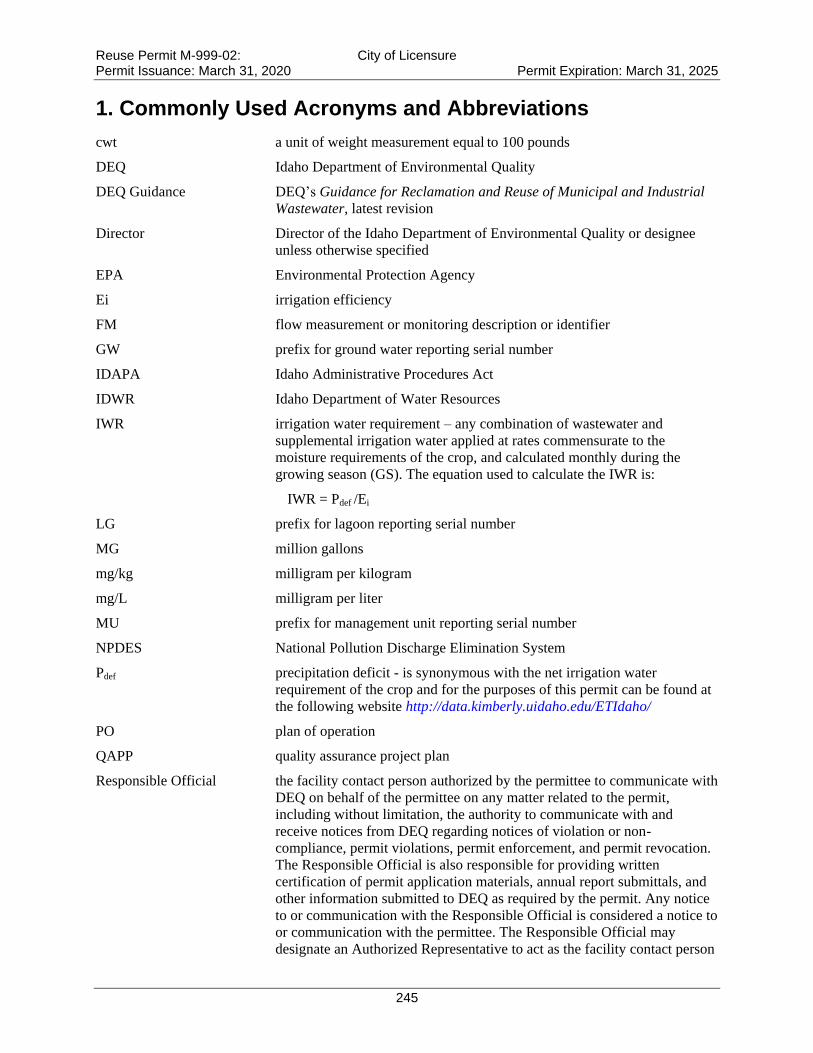
Reuse Permit M-999-02: City of Licensure Permit Issuance: March 31, 2020 Permit Expiration: March 31, 2025
245
1. Commonly Used Acronyms and Abbreviations
cwt a unit of weight measurement equal to 100 pounds
DEQ Idaho Department of Environmental Quality
DEQ Guidance DEQ’s Guidance for Reclamation and Reuse of Municipal and Industrial
Wastewater, latest revision
Director Director of the Idaho Department of Environmental Quality or designee
unless otherwise specified
EPA Environmental Protection Agency
Ei irrigation efficiency
FM flow measurement or monitoring description or identifier
GW prefix for ground water reporting serial number
IDAPA Idaho Administrative Procedures Act
IDWR Idaho Department of Water Resources
IWR irrigation water requirement – any combination of wastewater and
supplemental irrigation water applied at rates commensurate to the
moisture requirements of the crop, and calculated monthly during the
growing season (GS). The equation used to calculate the IWR is:
IWR = Pdef /Ei
LG prefix for lagoon reporting serial number
MG million gallons
mg/kg milligram per kilogram
mg/L milligram per liter
MU prefix for management unit reporting serial number
NPDES National Pollution Discharge Elimination System
Pdef precipitation deficit - is synonymous with the net irrigation water
requirement of the crop and for the purposes of this permit can be found at
the following website http://data.kimberly.uidaho.edu/ETIdaho/
PO plan of operation
QAPP quality assurance project plan
Responsible Official the facility contact person authorized by the permittee to communicate with
DEQ on behalf of the permittee on any matter related to the permit,
including without limitation, the authority to communicate with and
receive notices from DEQ regarding notices of violation or non-
compliance, permit violations, permit enforcement, and permit revocation.
The Responsible Official is also responsible for providing written
certification of permit application materials, annual report submittals, and
other information submitted to DEQ as required by the permit. Any notice
to or communication with the Responsible Official is considered a notice to
or communication with the permittee. The Responsible Official may
designate an Authorized Representative to act as the facility contact person

Reuse Permit M-999-02: City of Licensure Permit Issuance: March 31, 2020 Permit Expiration: March 31, 2025
246
for any of the activities or duties related to the permit, except signing and
certifying the permit application, which must be done by the Responsible
Official. The Authorized Representative shall act as the Responsible
Official and shall bind the permittee as described in this definition.
Designation of the Authorized Representative shall follow the requirements
specified in Section 6.1.3 of the permit.
SU prefix for soil monitoring unit reporting serial number
SW prefix for supplemental irrigation water reporting serial number
WW prefix for wastewater reporting serial number
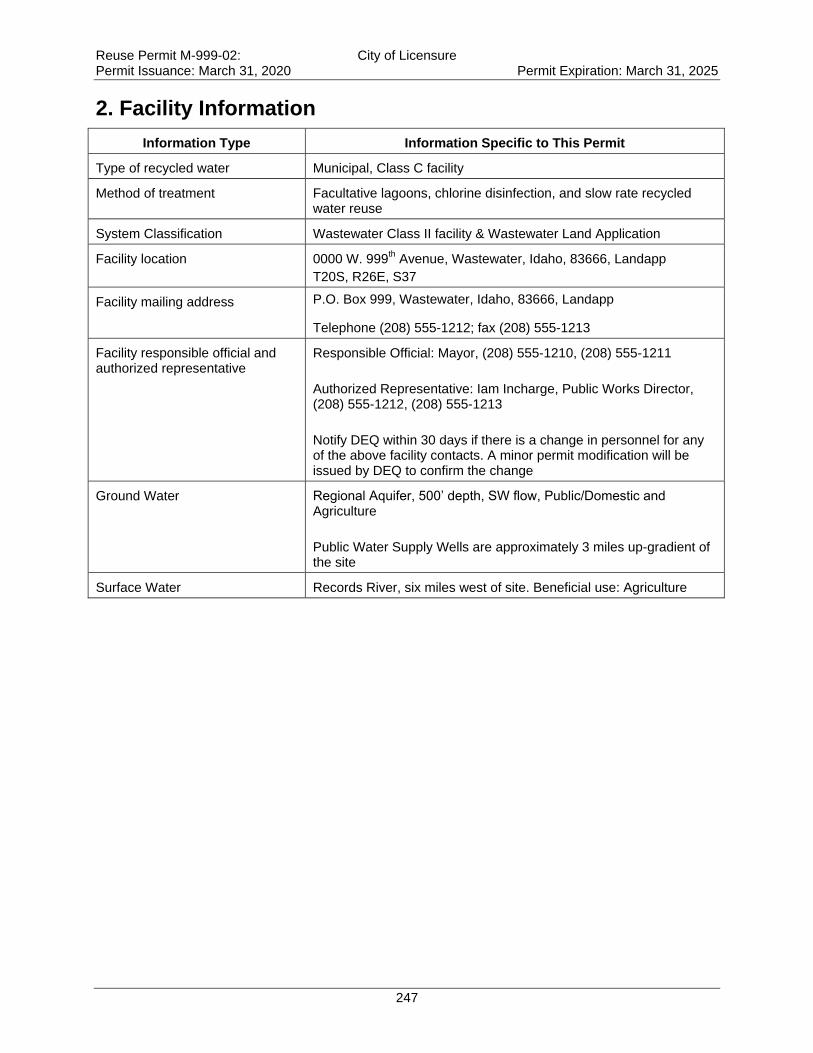
Reuse Permit M-999-02: City of Licensure Permit Issuance: March 31, 2020 Permit Expiration: March 31, 2025
247
2. Facility Information
Information Type Information Specific to This Permit
Type of recycled water Municipal, Class C facility
Method of treatment Facultative lagoons, chlorine disinfection, and slow rate recycled water reuse
System Classification Wastewater Class II facility & Wastewater Land Application
Facility location 0000 W. 999th Avenue, Wastewater, Idaho, 83666, Landapp
T20S, R26E, S37
Facility mailing address P.O. Box 999, Wastewater, Idaho, 83666, Landapp
Telephone (208) 555-1212; fax (208) 555-1213
Facility responsible official and authorized representative
Responsible Official: Mayor, (208) 555-1210, (208) 555-1211
Authorized Representative: Iam Incharge, Public Works Director, (208) 555-1212, (208) 555-1213
Notify DEQ within 30 days if there is a change in personnel for any of the above facility contacts. A minor permit modification will be issued by DEQ to confirm the change
Ground Water Regional Aquifer, 500’ depth, SW flow, Public/Domestic and Agriculture
Public Water Supply Wells are approximately 3 miles up-gradient of the site
Surface Water Records River, six miles west of site. Beneficial use: Agriculture

Reuse Permit M-999-02: City of Licensure Permit Issuance: March 31, 2020 Permit Expiration: March 31, 2025
248
3. Compliance Schedule for Required Activities
Compliance Activity (CA) Number and Completion Due
Date
Compliance Activity Description
CA-999-01
Twelve (12) months after permit issuance
Plan of Operation (PO): The permittee shall submit for review and approval a PO that reflects current operations and incorporates the requirements of this permit. The PO shall comply with the applicable requirements stated in IDAPA 58.01.17.300.05 and shall address applicable items in the Plan of Operation checklist in the DEQ Guidance.
The PO shall include the following site management plans or the permittee may submit the site management plans individually:
1. Buffer zone plan;
2. Cropping plan;
3. Emergency operating plan;
4. Grazing management plan;
5. Irrigation management and scheduling plan;
6. Nuisance and Odor management plan;
7. Runoff management plan;
8. Well location acceptability analysis;
9. Waste solids management plan
The PO shall be updated as needed to reflect current operations. The permittee shall notify DEQ of material changes to the PO and copies must be kept on site and made available to DEQ upon request.
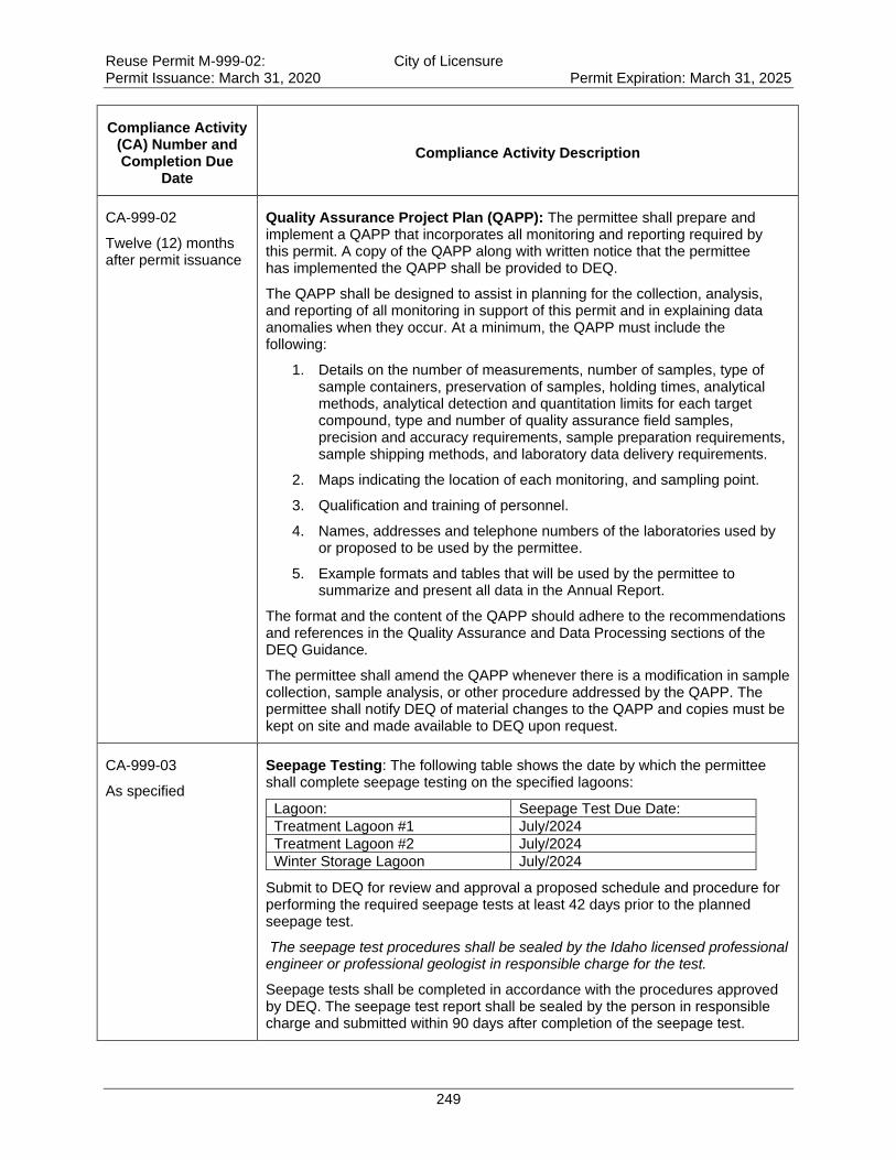
Reuse Permit M-999-02: City of Licensure Permit Issuance: March 31, 2020 Permit Expiration: March 31, 2025
249
Compliance Activity (CA) Number and Completion Due
Date
Compliance Activity Description
CA-999-02
Twelve (12) months after permit issuance
Quality Assurance Project Plan (QAPP): The permittee shall prepare and implement a QAPP that incorporates all monitoring and reporting required by this permit. A copy of the QAPP along with written notice that the permittee has implemented the QAPP shall be provided to DEQ.
The QAPP shall be designed to assist in planning for the collection, analysis, and reporting of all monitoring in support of this permit and in explaining data anomalies when they occur. At a minimum, the QAPP must include the following:
1. Details on the number of measurements, number of samples, type of sample containers, preservation of samples, holding times, analytical methods, analytical detection and quantitation limits for each target compound, type and number of quality assurance field samples, precision and accuracy requirements, sample preparation requirements, sample shipping methods, and laboratory data delivery requirements.
2. Maps indicating the location of each monitoring, and sampling point.
3. Qualification and training of personnel.
4. Names, addresses and telephone numbers of the laboratories used by or proposed to be used by the permittee.
5. Example formats and tables that will be used by the permittee to summarize and present all data in the Annual Report.
The format and the content of the QAPP should adhere to the recommendations and references in the Quality Assurance and Data Processing sections of the DEQ Guidance.
The permittee shall amend the QAPP whenever there is a modification in sample collection, sample analysis, or other procedure addressed by the QAPP. The permittee shall notify DEQ of material changes to the QAPP and copies must be kept on site and made available to DEQ upon request.
CA-999-03
As specified
Seepage Testing: The following table shows the date by which the permittee shall complete seepage testing on the specified lagoons:
Lagoon: Seepage Test Due Date:
Treatment Lagoon #1 July/2024
Treatment Lagoon #2 July/2024
Winter Storage Lagoon July/2024
Submit to DEQ for review and approval a proposed schedule and procedure for performing the required seepage tests at least 42 days prior to the planned seepage test.
The seepage test procedures shall be sealed by the Idaho licensed professional engineer or professional geologist in responsible charge for the test.
Seepage tests shall be completed in accordance with the procedures approved by DEQ. The seepage test report shall be sealed by the person in responsible charge and submitted within 90 days after completion of the seepage test.
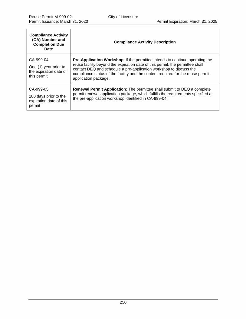
Reuse Permit M-999-02: City of Licensure Permit Issuance: March 31, 2020 Permit Expiration: March 31, 2025
250
Compliance Activity (CA) Number and Completion Due
Date
Compliance Activity Description
CA-999-04
One (1) year prior to the expiration date of this permit
Pre-Application Workshop: If the permittee intends to continue operating the reuse facility beyond the expiration date of this permit, the permittee shall contact DEQ and schedule a pre-application workshop to discuss the compliance status of the facility and the content required for the reuse permit application package.
CA-999-05
180 days prior to the expiration date of this permit
Renewal Permit Application: The permittee shall submit to DEQ a complete permit renewal application package, which fulfills the requirements specified at the pre-application workshop identified in CA-999-04.
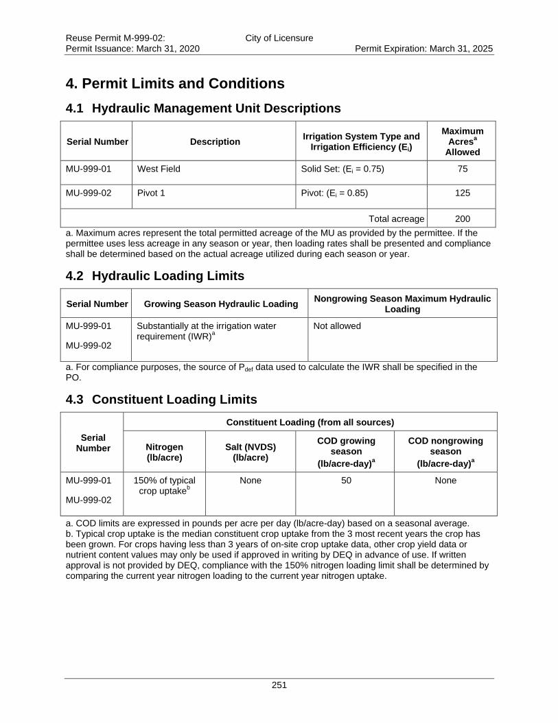
Reuse Permit M-999-02: City of Licensure Permit Issuance: March 31, 2020 Permit Expiration: March 31, 2025
251
4. Permit Limits and Conditions
4.1 Hydraulic Management Unit Descriptions
Serial Number Description Irrigation System Type and
Irrigation Efficiency (Ei)
Maximum Acres
a
Allowed
MU-999-01 West Field Solid Set: (Ei = 0.75) 75
MU-999-02 Pivot 1 Pivot: (Ei = 0.85) 125
Total acreage 200
a. Maximum acres represent the total permitted acreage of the MU as provided by the permittee. If the permittee uses less acreage in any season or year, then loading rates shall be presented and compliance shall be determined based on the actual acreage utilized during each season or year.
4.2 Hydraulic Loading Limits
Serial Number Growing Season Hydraulic Loading Nongrowing Season Maximum Hydraulic
Loading
MU-999-01
MU-999-02
Substantially at the irrigation water requirement (IWR)
a
Not allowed
a. For compliance purposes, the source of Pdef data used to calculate the IWR shall be specified in the PO.
4.3 Constituent Loading Limits
Serial Number
Constituent Loading (from all sources)
Nitrogen (lb/acre)
Salt (NVDS) (lb/acre)
COD growing season
(lb/acre-day)a
COD nongrowing season
(lb/acre-day)a
MU-999-01
MU-999-02
150% of typical crop uptake
b
None 50 None
a. COD limits are expressed in pounds per acre per day (lb/acre-day) based on a seasonal average. b. Typical crop uptake is the median constituent crop uptake from the 3 most recent years the crop has been grown. For crops having less than 3 years of on-site crop uptake data, other crop yield data or nutrient content values may only be used if approved in writing by DEQ in advance of use. If written approval is not provided by DEQ, compliance with the 150% nitrogen loading limit shall be determined by comparing the current year nitrogen loading to the current year nitrogen uptake.
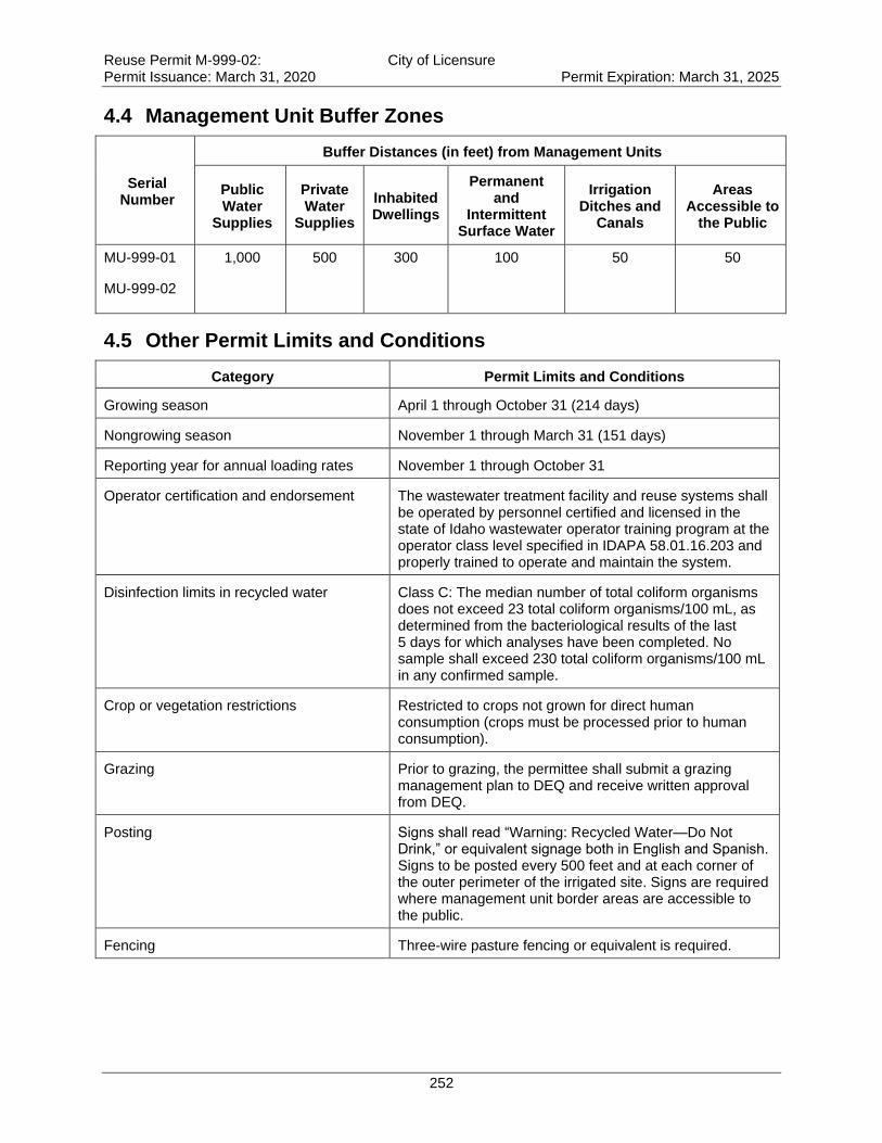
Reuse Permit M-999-02: City of Licensure Permit Issuance: March 31, 2020 Permit Expiration: March 31, 2025
252
4.4 Management Unit Buffer Zones
Serial Number
Buffer Distances (in feet) from Management Units
Public Water
Supplies
Private Water
Supplies
Inhabited Dwellings
Permanent and
Intermittent Surface Water
Irrigation Ditches and
Canals
Areas Accessible to
the Public
MU-999-01
MU-999-02
1,000 500 300 100 50 50
4.5 Other Permit Limits and Conditions
Category Permit Limits and Conditions
Growing season April 1 through October 31 (214 days)
Nongrowing season November 1 through March 31 (151 days)
Reporting year for annual loading rates November 1 through October 31
Operator certification and endorsement
The wastewater treatment facility and reuse systems shall be operated by personnel certified and licensed in the state of Idaho wastewater operator training program at the operator class level specified in IDAPA 58.01.16.203 and properly trained to operate and maintain the system.
Disinfection limits in recycled water Class C: The median number of total coliform organisms does not exceed 23 total coliform organisms/100 mL, as determined from the bacteriological results of the last 5 days for which analyses have been completed. No sample shall exceed 230 total coliform organisms/100 mL in any confirmed sample.
Crop or vegetation restrictions Restricted to crops not grown for direct human consumption (crops must be processed prior to human consumption).
Grazing Prior to grazing, the permittee shall submit a grazing management plan to DEQ and receive written approval from DEQ.
Posting Signs shall read “Warning: Recycled Water—Do Not Drink,” or equivalent signage both in English and Spanish. Signs to be posted every 500 feet and at each corner of the outer perimeter of the irrigated site. Signs are required where management unit border areas are accessible to the public.
Fencing Three-wire pasture fencing or equivalent is required.

Reuse Permit M-999-02: City of Licensure Permit Issuance: March 31, 2020 Permit Expiration: March 31, 2025
253
Category Permit Limits and Conditions
Construction Plans
Pursuant to Idaho Code §39-118, IDAPA 58.01.16, and IDAPA 58.01.17, detailed plans and specifications shall be submitted to DEQ for review and approval prior to construction, modification, or expansion of any wastewater treatment, storage, conveyance structures, or reuse facility. Inspection requirements shall be satisfied and within 30 days of completion of construction and the permittee shall submit as-built plans or a letter from an Idaho Professional Engineer certifying the facilities or structures were constructed in substantial accordance with the approved plans and specifications.
Backflow prevention and testing requirements
Backflow prevention is required to protect surface water and ground water from an unauthorized discharge of recycled water or wastewater. Refer to section 9.1.1 of this permit.
Records retention requirements Keep records generated to meet the requirements of this permit for the duration of the permit, including administrative extensions, plus 2 years.
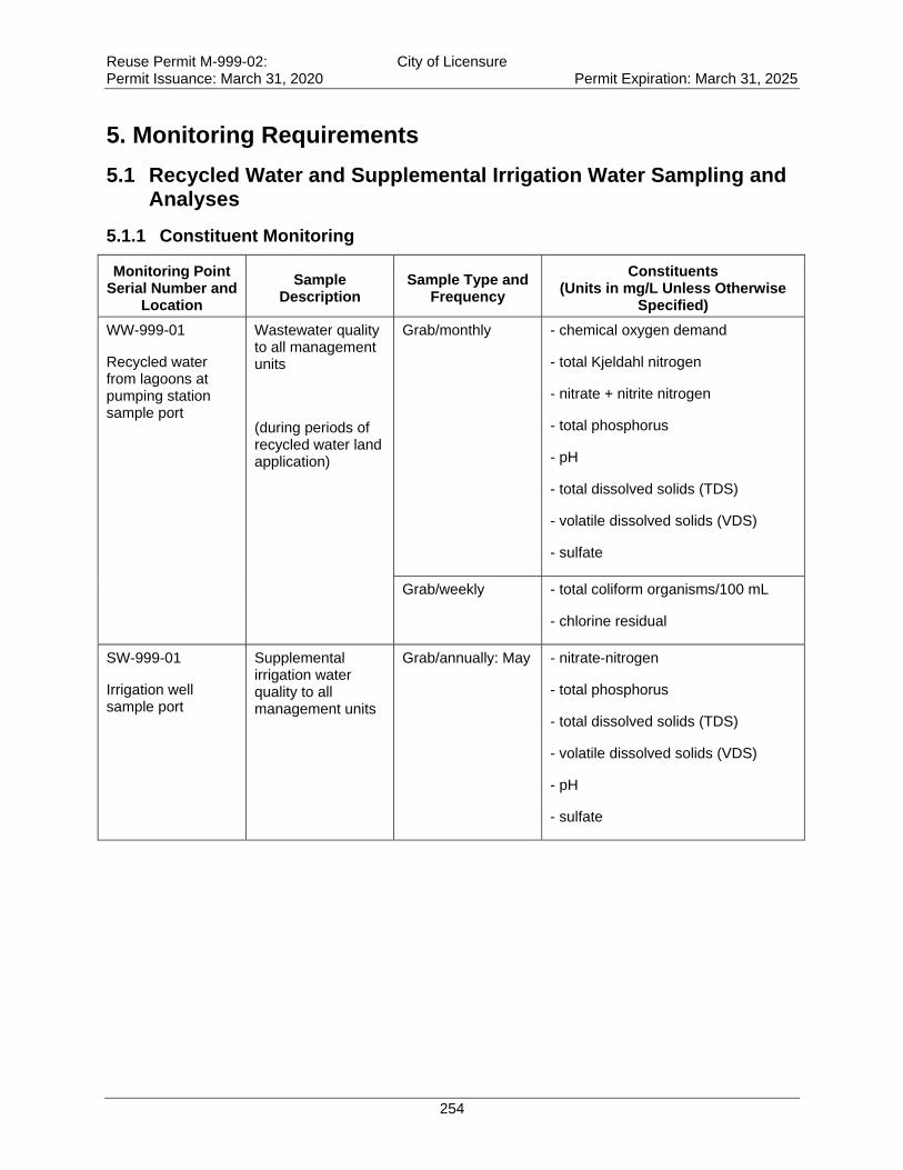
Reuse Permit M-999-02: City of Licensure Permit Issuance: March 31, 2020 Permit Expiration: March 31, 2025
254
5. Monitoring Requirements
5.1 Recycled Water and Supplemental Irrigation Water Sampling and Analyses
5.1.1 Constituent Monitoring
Monitoring Point Serial Number and
Location
Sample Description
Sample Type and Frequency
Constituents (Units in mg/L Unless Otherwise
Specified)
WW-999-01
Recycled water from lagoons at pumping station sample port
Wastewater quality to all management units
(during periods of recycled water land application)
Grab/monthly
- chemical oxygen demand
- total Kjeldahl nitrogen
- nitrate + nitrite nitrogen
- total phosphorus
- pH
- total dissolved solids (TDS)
- volatile dissolved solids (VDS)
- sulfate
Grab/weekly - total coliform organisms/100 mL
- chlorine residual
SW-999-01
Irrigation well sample port
Supplemental irrigation water quality to all management units
Grab/annually: May - nitrate-nitrogen
- total phosphorus
- total dissolved solids (TDS)
- volatile dissolved solids (VDS)
- pH
- sulfate
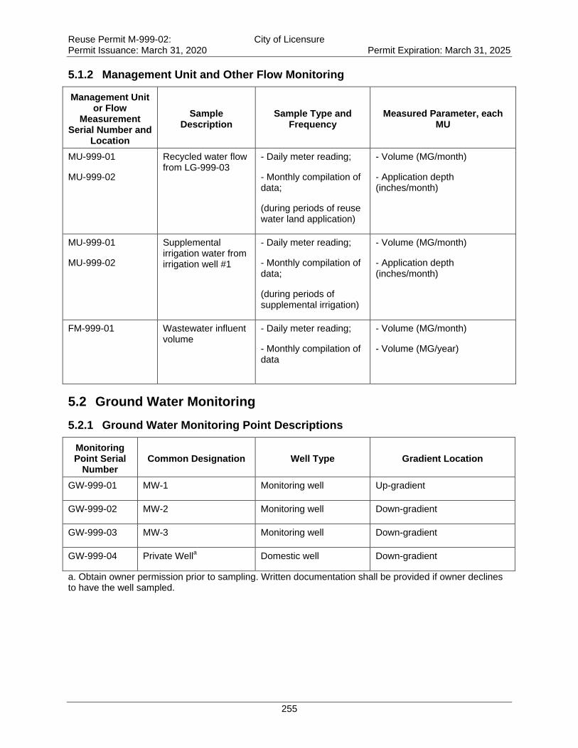
Reuse Permit M-999-02: City of Licensure Permit Issuance: March 31, 2020 Permit Expiration: March 31, 2025
255
5.1.2 Management Unit and Other Flow Monitoring
Management Unit or Flow
Measurement Serial Number and
Location
Sample Description
Sample Type and Frequency
Measured Parameter, each MU
MU-999-01
MU-999-02
Recycled water flow from LG-999-03
- Daily meter reading;
- Monthly compilation of data;
(during periods of reuse water land application)
- Volume (MG/month)
- Application depth (inches/month)
MU-999-01
MU-999-02
Supplemental irrigation water from irrigation well #1
- Daily meter reading;
- Monthly compilation of data;
(during periods of supplemental irrigation)
- Volume (MG/month)
- Application depth (inches/month)
FM-999-01
Wastewater influent volume
- Daily meter reading;
- Monthly compilation of data
- Volume (MG/month)
- Volume (MG/year)
5.2 Ground Water Monitoring
5.2.1 Ground Water Monitoring Point Descriptions
Monitoring Point Serial
Number Common Designation Well Type Gradient Location
GW-999-01 MW-1 Monitoring well Up-gradient
GW-999-02 MW-2 Monitoring well Down-gradient
GW-999-03 MW-3 Monitoring well Down-gradient
GW-999-04 Private Wella Domestic well Down-gradient
a. Obtain owner permission prior to sampling. Written documentation shall be provided if owner declines to have the well sampled.
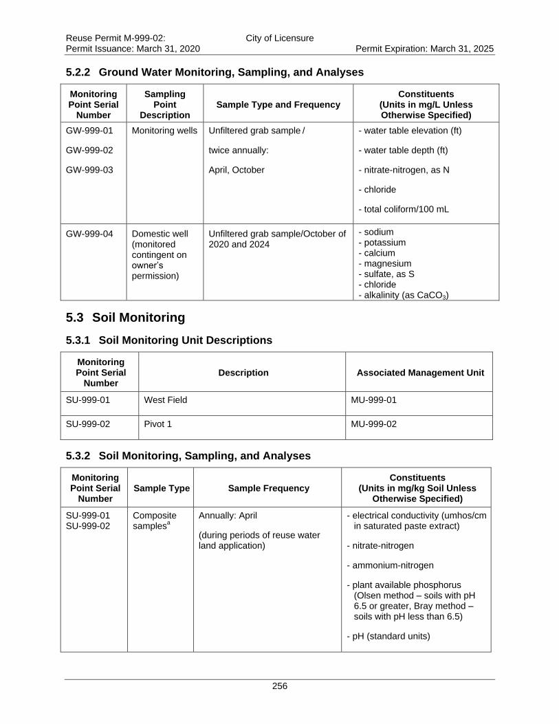
Reuse Permit M-999-02: City of Licensure Permit Issuance: March 31, 2020 Permit Expiration: March 31, 2025
256
5.2.2 Ground Water Monitoring, Sampling, and Analyses
Monitoring Point Serial
Number
Sampling Point
Description Sample Type and Frequency
Constituents (Units in mg/L Unless Otherwise Specified)
GW-999-01
GW-999-02
GW-999-03
Monitoring wells Unfiltered grab sample /
twice annually:
April, October
- water table elevation (ft)
- water table depth (ft)
- nitrate-nitrogen, as N
- chloride
- total coliform/100 mL
GW-999-04 Domestic well (monitored contingent on owner’s permission)
Unfiltered grab sample/October of 2020 and 2024
- sodium - potassium - calcium - magnesium - sulfate, as S - chloride - alkalinity (as CaCO3)
5.3 Soil Monitoring
5.3.1 Soil Monitoring Unit Descriptions
Monitoring Point Serial
Number Description Associated Management Unit
SU-999-01 West Field MU-999-01
SU-999-02 Pivot 1 MU-999-02
5.3.2 Soil Monitoring, Sampling, and Analyses
Monitoring Point Serial
Number Sample Type Sample Frequency
Constituents (Units in mg/kg Soil Unless
Otherwise Specified)
SU-999-01 SU-999-02
Composite samples
a
Annually: April
(during periods of reuse water land application)
- electrical conductivity (umhos/cm in saturated paste extract)
- nitrate-nitrogen
- ammonium-nitrogen
- plant available phosphorus (Olsen method – soils with pH 6.5 or greater, Bray method – soils with pH less than 6.5)
- pH (standard units)
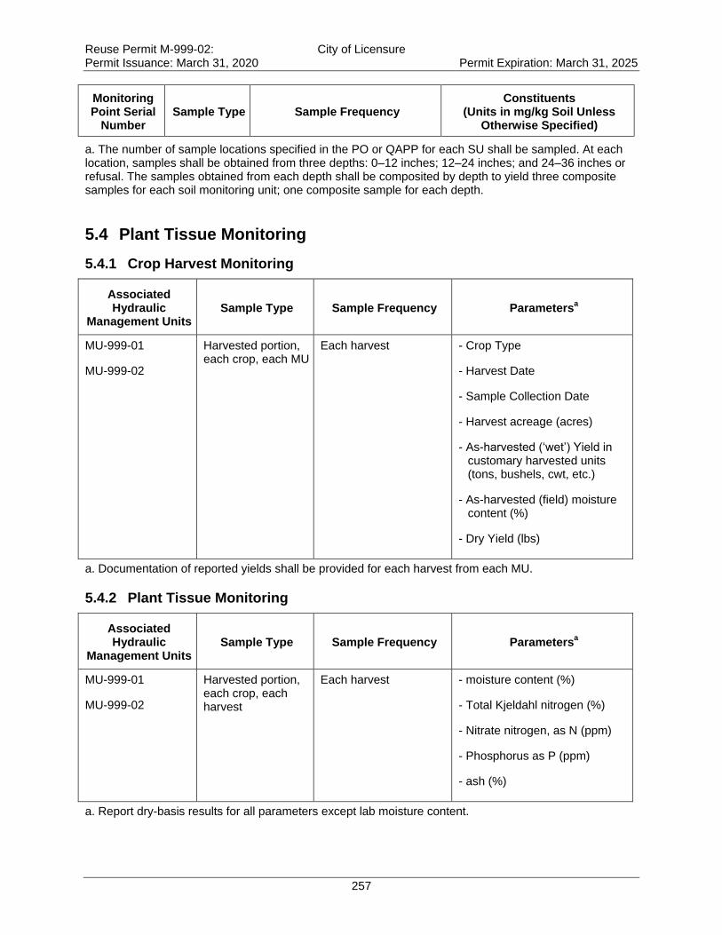
Reuse Permit M-999-02: City of Licensure Permit Issuance: March 31, 2020 Permit Expiration: March 31, 2025
257
Monitoring Point Serial
Number Sample Type Sample Frequency
Constituents (Units in mg/kg Soil Unless
Otherwise Specified)
a. The number of sample locations specified in the PO or QAPP for each SU shall be sampled. At each location, samples shall be obtained from three depths: 0–12 inches; 12–24 inches; and 24–36 inches or refusal. The samples obtained from each depth shall be composited by depth to yield three composite samples for each soil monitoring unit; one composite sample for each depth.
5.4 Plant Tissue Monitoring
5.4.1 Crop Harvest Monitoring
Associated Hydraulic
Management Units Sample Type Sample Frequency Parameters
a
MU-999-01
MU-999-02
Harvested portion, each crop, each MU
Each harvest
- Crop Type
- Harvest Date
- Sample Collection Date
- Harvest acreage (acres)
- As-harvested (‘wet’) Yield in customary harvested units (tons, bushels, cwt, etc.)
- As-harvested (field) moisture content (%)
- Dry Yield (lbs)
a. Documentation of reported yields shall be provided for each harvest from each MU.
5.4.2 Plant Tissue Monitoring
Associated Hydraulic
Management Units Sample Type Sample Frequency Parameters
a
MU-999-01
MU-999-02
Harvested portion, each crop, each harvest
Each harvest
- moisture content (%)
- Total Kjeldahl nitrogen (%)
- Nitrate nitrogen, as N (ppm)
- Phosphorus as P (ppm)
- ash (%)
a. Report dry-basis results for all parameters except lab moisture content.
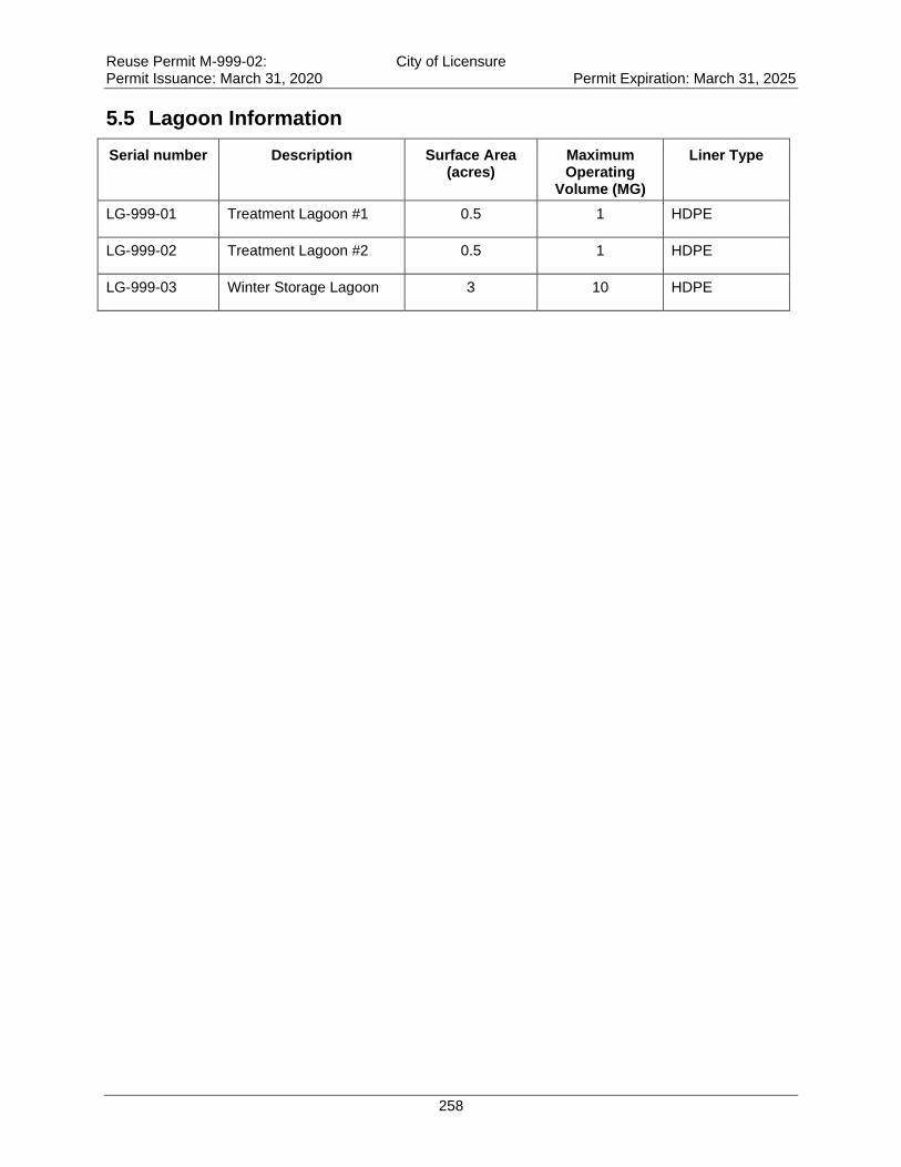
Reuse Permit M-999-02: City of Licensure Permit Issuance: March 31, 2020 Permit Expiration: March 31, 2025
258
5.5 Lagoon Information
Serial number Description Surface Area (acres)
Maximum Operating
Volume (MG)
Liner Type
LG-999-01 Treatment Lagoon #1 0.5 1 HDPE
LG-999-02 Treatment Lagoon #2 0.5 1 HDPE
LG-999-03 Winter Storage Lagoon 3 10 HDPE
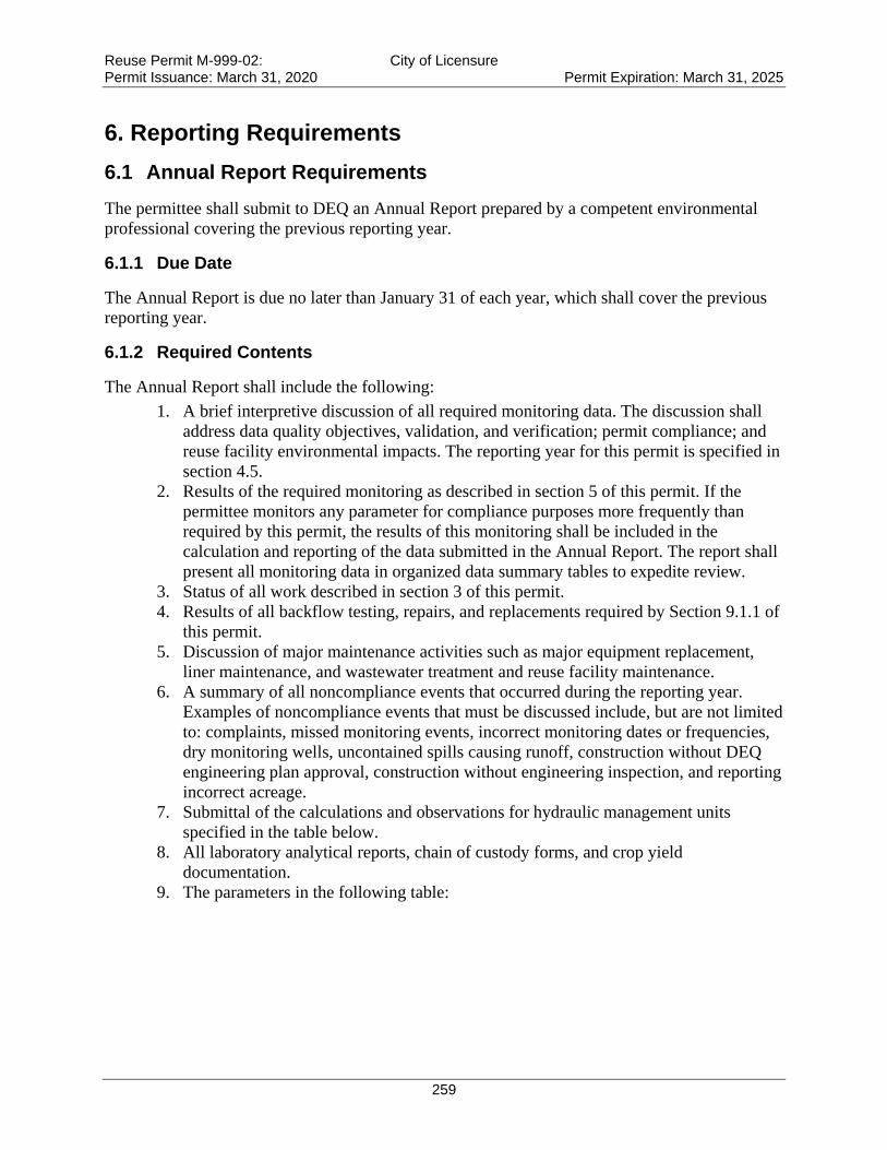
Reuse Permit M-999-02: City of Licensure Permit Issuance: March 31, 2020 Permit Expiration: March 31, 2025
259
6. Reporting Requirements
6.1 Annual Report Requirements
The permittee shall submit to DEQ an Annual Report prepared by a competent environmental
professional covering the previous reporting year.
6.1.1 Due Date
The Annual Report is due no later than January 31 of each year, which shall cover the previous
reporting year.
6.1.2 Required Contents
The Annual Report shall include the following:
1. A brief interpretive discussion of all required monitoring data. The discussion shall
address data quality objectives, validation, and verification; permit compliance; and
reuse facility environmental impacts. The reporting year for this permit is specified in
section 4.5.
2. Results of the required monitoring as described in section 5 of this permit. If the
permittee monitors any parameter for compliance purposes more frequently than
required by this permit, the results of this monitoring shall be included in the
calculation and reporting of the data submitted in the Annual Report. The report shall
present all monitoring data in organized data summary tables to expedite review.
3. Status of all work described in section 3 of this permit.
4. Results of all backflow testing, repairs, and replacements required by Section 9.1.1 of
this permit.
5. Discussion of major maintenance activities such as major equipment replacement,
liner maintenance, and wastewater treatment and reuse facility maintenance.
6. A summary of all noncompliance events that occurred during the reporting year.
Examples of noncompliance events that must be discussed include, but are not limited
to: complaints, missed monitoring events, incorrect monitoring dates or frequencies,
dry monitoring wells, uncontained spills causing runoff, construction without DEQ
engineering plan approval, construction without engineering inspection, and reporting
incorrect acreage.
7. Submittal of the calculations and observations for hydraulic management units
specified in the table below.
8. All laboratory analytical reports, chain of custody forms, and crop yield
documentation.
9. The parameters in the following table:
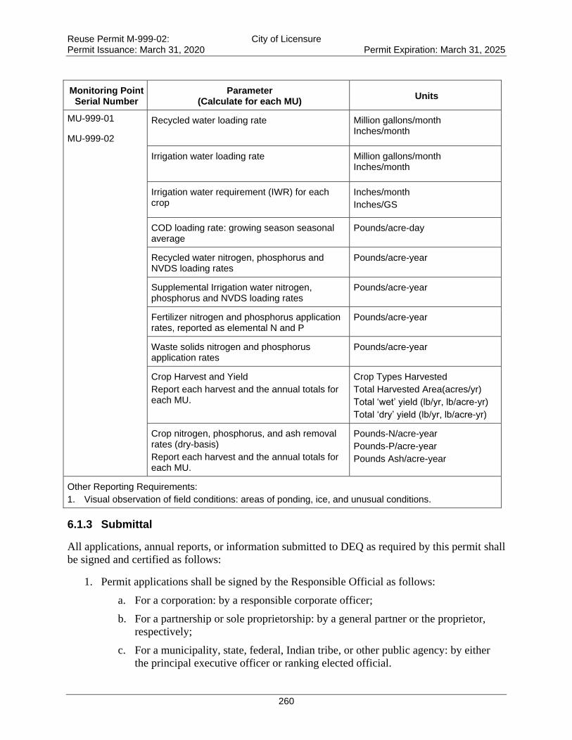
Reuse Permit M-999-02: City of Licensure Permit Issuance: March 31, 2020 Permit Expiration: March 31, 2025
260
Monitoring Point Serial Number
Parameter (Calculate for each MU)
Units
MU-999-01
MU-999-02
Recycled water loading rate Million gallons/month Inches/month
Irrigation water loading rate Million gallons/month Inches/month
Irrigation water requirement (IWR) for each crop
Inches/month
Inches/GS
COD loading rate: growing season seasonal average
Pounds/acre-day
Recycled water nitrogen, phosphorus and NVDS loading rates
Pounds/acre-year
Supplemental Irrigation water nitrogen, phosphorus and NVDS loading rates
Pounds/acre-year
Fertilizer nitrogen and phosphorus application rates, reported as elemental N and P
Pounds/acre-year
Waste solids nitrogen and phosphorus application rates
Pounds/acre-year
Crop Harvest and Yield
Report each harvest and the annual totals for each MU.
Crop Types Harvested
Total Harvested Area(acres/yr)
Total ‘wet’ yield (lb/yr, lb/acre-yr)
Total ‘dry’ yield (lb/yr, lb/acre-yr)
Crop nitrogen, phosphorus, and ash removal rates (dry-basis)
Report each harvest and the annual totals for each MU.
Pounds-N/acre-year
Pounds-P/acre-year
Pounds Ash/acre-year
Other Reporting Requirements:
1. Visual observation of field conditions: areas of ponding, ice, and unusual conditions.
6.1.3 Submittal
All applications, annual reports, or information submitted to DEQ as required by this permit shall
be signed and certified as follows:
1. Permit applications shall be signed by the Responsible Official as follows:
a. For a corporation: by a responsible corporate officer;
b. For a partnership or sole proprietorship: by a general partner or the proprietor,
respectively;
c. For a municipality, state, federal, Indian tribe, or other public agency: by either
the principal executive officer or ranking elected official.
Reuse Permit M-999-02: City of Licensure Permit Issuance: March 31, 2020 Permit Expiration: March 31, 2025
261
2. Annual reports and other information requested by DEQ shall be signed by the
Responsible Official or by a duly Authorized Representative of that person. A person is a
duly Authorized Representative only if:
a. The authorization is made in writing by the responsible official;
b. The authorization specifies either an individual or position having responsibility
for the overall operation or the regulated facility, such as the position of plant
manager, superintendent, position of equivalent responsibility, or an individual
having overall responsibility for environmental matters for the company; and
c. The written authorization is submitted to DEQ.
Submit the annual report to the following DEQ regional office at this address:
Engineering Manager
Idaho Department of Environmental Quality
Boise Regional Office
1445 N. Orchard
Boise, ID 83706
The annual report shall include the following certification statement and be signed, dated, and
certified by the permittee’s Responsible Official or Authorized Representative:
“I certify that the information in this submittal was prepared in conformance with the
Quality Assurance Project Plan required by permit M-999-02, and is to the best of my
knowledge, true, accurate and complete and I acknowledge that knowing submission of
false or incomplete information may result in permit revocation as provided for in
IDAPA 58.01.17.920.01 or other enforcement action as provided for under Idaho law.”
6.2 Emergency and Noncompliance Reporting
Report noncompliance incidents to DEQ’s regional office at (208) 373-0550 or 1-888-800-3480.
In case of emergencies, call the emergency 24-hour number at 1-800-632-8000 and DEQ’s
regional office.
See Section 8, “Standard Permit Conditions,” and IDAPA 58.01.17.500.06 for reporting requirements
for facilities.
All instances of unpermitted discharges of wastewater to Surface Waters of the United States
shall also be reported to the Environmental Protection Agency by telephone within 24 hours
from the time the permittee becomes aware of the discharge and in writing within five days at
this address:
NPDES/Stormwater Coordinator, USEPA Idaho Operations Office
950 W. Bannock, Suite 900
Boise, ID 83702
208-378-5746 / 208-378-5744 and EPA Hot Line (206) 553-1846
Reuse Permit M-999-02: City of Licensure Permit Issuance: March 31, 2020 Permit Expiration: March 31, 2025
262
7. Reserved
8. Standard Permit Conditions
The following standard permit conditions are included as terms of this permit as required by the
“Recycled Water Rules,” (IDAPA 58.01.17.500).
500. STANDARD PERMIT CONDITIONS.
The following conditions shall apply to and be included in all permits. (4-1-88)
01. Compliance Required. The permittee shall comply with all conditions of the permit . (4-1-88)
02. Renewal Responsibilities. If the permittee intends to continue operation of the permitted facility after the
expiration of an existing permit, the permittee shall apply for a new permit in accordance with
these rules. (4-1-88)
03. Operation of Facilities. The permittee shall at all times properly maintain and operate all structures,
systems, and equipment for treatment, control and monitoring, which are installed or used by the permittee to
achieve compliance with the permit or these rules. (4-1-88)
04. Provide Information. The permittee shall furnish to the Director within a reasonable time, any information
including copies of records, which may be requested by the Director to determine whether cause exists for
modifying, revoking, re-issuing, or terminating the permit, or to determine compliance with the permit or these
rules. (4-1-88)
05. Entry and Access. The permittee shall allow the Director, consistent with Title 39, Chapter 1, Idaho Code,
to: (4-1-88)
a. Enter the permitted facility. (4-1-88)
b. Inspect any records that must be kept under the conditions of the permit. (4-1-88)
c. Inspect any facility, equipment, practice, or operation permitted or required by the permit. (4-1-88)
d. Sample or monitor for the purpose of assuring permit compliance, any substance or any parameter at the
facility. (4-1-88)
Reuse Permit M-999-02: City of Licensure Permit Issuance: March 31, 2020 Permit Expiration: March 31, 2025
263
06. Reporting. The permittee shall report to the Director under the circumstances and in the manner specified
in this section: (4-1-88)
a. In writing at least thirty (30) days before any planned physical alteration or addition to the permitted
facility or activity if that alteration or addition would result in any significant change in information that was
submitted during the permit application process. When the alteration or addition results in a need for a major
modification, such alteration or addition shall not be made prior to Department approval issued in accordance with
these rules. (4-7-11)
b. In writing thirty (30) days before any anticipated change which would result in noncompliance with any
permit condition or these rules. (4-1-88)
c. Orally within twenty-four (24) hours from the time the permittee became aware of any noncompliance
which may endanger the public health or the environment at telephone numbers provided in the permit by the
Director. (4-1-88)
d. In writing as soon as possible but within five (5) days of the date the permittee knows or should know of
any noncompliance unless extended by the Department. This report shall contain: (4-1-88)
i. A description of the noncompliance and its cause; (4-1-88)
ii. The period of noncompliance including to the extent possible, times and dates and, if the noncompliance
has not been corrected, the anticipated length of time it is expected to continue; and (4-7-11)
iii. Steps taken or planned, including timelines, to reduce or eliminate the continuance or reoccurrence of the
noncompliance. (4-7-11)
e. In writing as soon as possible after the permittee becomes aware of relevant facts not submitted or incorrect
information submitted, in a permit application or any report to the Director. Those facts or the correct information
shall be included as a part of this report. (4-1-88)
07. Minimize Impacts. The permittee shall take all necessary actions to eliminate and correct any adverse
impact on the public health or the environment resulting from permit noncompliance. (4-1-88)
08. Compliance with “Ground Water Quality Rule.” Permits issued pursuant to these rules shall require
compliance with IDAPA 58.01.11, “Ground Water Quality Rule.” (4-7-11)
Reuse Permit M-999-02: City of Licensure Permit Issuance: March 31, 2020 Permit Expiration: March 31, 2025
264
9. General Permit Conditions
The following general permit conditions are based on the cited rules at the time of issuance and
are enforceable as part of this permit. Note that the rules cited in this section, and elsewhere in
this permit, are supplemented by the rules themselves. Rules applicable to your facility are
enforceable whether or not they appear in this permit.
9.1 Operations
9.1.1 Backflow Prevention
Reuse facilities with existing or planned cross-connections or interconnections between the
recycled water system and any water supply (potable or nonpotable), or surface water, shall have
backflow prevention assemblies, devices, or methods as required by the applicable rule or as
specified in this permit and approved by DEQ.
For public water systems, backflow assemblies shall meet the requirements of IDAPA
58.01.08.543. Assemblies shall be adequately maintained and shall be tested annually by a
certified backflow assembly tester, and repaired or replaced as necessary to maintain operational
status.
For domestic water supply wells, backflow prevention devices shall meet the requirements of
IDAPA 07.02.04 and shall be adequately operated and maintained.
Irrigation water supply wells shall meet the requirements of IDAPA 37.03.09.36 for preventing
any waste or contamination of the ground water resource. Backflow prevention assemblies or
devices used to protect the ground water shall be adequately operated and maintained.
Discharge of recycled water to surface water is regulated by the EPA NPDES program. An
NPDES permit is required for any discharge to surface water and backflow prevention shall be
implemented to prevent any unauthorized discharge. Backflow prevention assemblies or devices
used to protect the ground water shall be adequately operated and maintained.
Records of all testable backflow assembly test results, repairs, and replacements shall be kept at
the reuse facility along with other operational records, and shall be discussed in the Annual
Report and made available for inspection by DEQ. Other approved means of backflow
prevention, such as siphons and air-gap structures that cannot be tested, shall be maintained in
operable order.
9.1.2 Restricted to Premises
Wastewaters or recharge waters applied to the land surface must be restricted to the premises of
the application site. Wastewater discharges to surface water that require a permit under the Clean
Water Act must be authorized by the United States Environmental Protection Agency
(IDAPA 58.01.16.600.02).
9.1.3 Health Hazards, Nuisances, and Odors Prohibited
Health hazards, nuisances, and odors are prohibited as follows:

Reuse Permit M-999-02: City of Licensure Permit Issuance: March 31, 2020 Permit Expiration: March 31, 2025
265
Wastewater must not create a public health hazard or nuisance condition
(IDAPA 58.01.16.600.03).
No person shall allow, suffer, cause or permit the emission of odorous gases, liquids, or
solids into the atmosphere in such quantities as to cause air pollution
(IDAPA 58.01.01.776.01).
Air Pollution. The presence in the outdoor atmosphere of any air pollutant or combination
thereof in such quantity of such nature and duration and under such conditions as would
be injurious to human health or welfare, to animal or plant life, or to property, or to
interfere unreasonably with the enjoyment of life or property (IDAPA 58.01.01.006.06).
9.1.4 Solids Management
Biosolids are the nutrient-rich organic materials resulting from the treatment of sewage sludge.
When treated and processed, sewage sludge becomes biosolids which can be safely recycled and
applied as fertilizer to sustainably improve and maintain productive soils and stimulate plant
growth.
Biosolids generated from sewage sludge are regulated by EPA under 40 CFR Part 503 and
require a DEQ approved sludge disposal plan as outlined in IDAPA 58.01.16.650. Contact DEQ
prior to application of biosolids at any permitted reuse facility.
Sludge is the semi-liquid mass produced and removed by wastewater treatment processes. This
does not include grit, garbage, and large solids.
Sludge is generated by wastewater treatment processes at municipal and industrial facilities.
Solid Waste is any garbage or refuse, sludge from a waste water treatment plant, water supply
treatment plant, or air pollution control facility and other discarded material including solid,
liquid, semi-solid, or contained gaseous material resulting from industrial, commercial, mining,
and agricultural operations and from community activities, but does not include solid or
dissolved materials in domestic sewage, or solid or dissolved material in irrigation return flows
or industrial discharges which are point sources subject to permits under Section 402 of the
Federal Water Pollution Control Act, as amended or source, special nuclear, or by-product
material as defined by the Atomic Energy Act of 1954, as amended.
Solid waste does not include inert wastes, manures and crop residues ultimately returned to the
soils at agronomic rates, and any agricultural solid waste which is managed and regulated
pursuant to rules adopted by the Idaho Department of Agriculture. DEQ reserves the right to use
existing authorities to regulate agricultural waste that impacts human health or the environment.
Solid waste is regulated under “Solid Waste Management Rules”, IDAPA 58.01.06. Wastes
otherwise regulated by DEQ (i.e. this permit) are not regulated under 58.01.06.
Waste Solids include sludge and wastes otherwise regulated by DEQ in accordance with IDAPA
58.01.06.001.03.a.xii. Waste solids may include vegetative waste, silt and mud containing
organic matter, and other non-inert solid wastes.
Inert wastes are defined as non-combustible, nonhazardous, and non-putrescible solids wastes
that are likely to retain their physical and chemical structure and have a de minimis potential to
Reuse Permit M-999-02: City of Licensure Permit Issuance: March 31, 2020 Permit Expiration: March 31, 2025
266
generate leachate under expected conditions of disposal, which includes resistance to biological
attack.
Waste solids require a DEQ approved sludge disposal plan as outlined in IDAPA 58.01.16.650.
9.1.5 Temporary Cessation of Operations and Closure (IDAPA 58.01.17.801)
Temporary cessation of operations and closure must be addressed as follows:
01. Temporary Cessation. A permittee shall implement any applicable conditions specified in the permit for
temporary cessation of operations. When the permit does not specify applicable temporary cessation conditions, the
permittee shall notify the Director prior to a temporary cessation of operations at the facility greater than sixty (60)
days in duration and any cessation not for regular maintenance or repair. Cessation of operations necessary for
regular maintenance or repair of a duration of sixty (60) days or less are not required to notify the Department under
this section. All notifications required under this section shall include a proposed temporary cessation plan that will
ensure the cessation of operations will not pose a threat to human health or the environment. (4-7-11)
02. Closure. A closure plan shall be required when a facility is closed voluntarily and when a permit is revoked
or expires. A permittee shall implement any applicable conditions specified in the permit for closure of the facility.
Unless otherwise directed by the terms of the permit or by the Director, the permittee shall submit a closure plan to
the Director for approval at least ninety (90) days prior to ceasing operations. The closure plan shall ensure that the
closed facility will not pose a threat to human health and the environment. Closure plan approval may be
conditioned upon a permittee’s agreement to complete such site investigations, monitoring, and any necessary
remediation activities that may be required. (4-7-11)
9.1.6 Plan of Operation (IDAPA 58.01.17.300.05)
The PO must comply with the following:
05. Reuse Facility Operation and Maintenance Manual or Plan of Operations. A facility’s operation and
maintenance manual must contain all system components relating to the reuse facility in order to comply with
IDAPA 58.01.16 “Wastewater Rules,” Section 425. Manuals and manual amendments are subject to the review and
approval provision therein. In addition to the content required by IDAPA 58.01.16.425, manuals for reuse facilities
shall include, if applicable: operation and management responsibility, permits and standards, general plant
description, operation and control of unit operations, land application site maps, wastewater characterization,
cropping plan, hydraulic loading rate, constituent loading rates, compliance activities, seepage rate testing, site
management plans, monitoring, site operations and maintenance, solids handling and processing, laboratory testing,
general maintenance, records and reports, store room and inventory, personnel, an emergency operating plan, and
any other information required by the Department. (4-7-11)
9.1.7 Seepage Testing Requirements (IDAPA 58.01.16.493.02.c)
Subsequent Tests. All lagoons covered under these rules must be seepage tested by an Idaho licensed
professional engineer, an Idaho licensed professional geologist, or by individuals under their supervision every ten
(10) years after the initial testing. (5-8-09)
9.1.8 Ground Water Quality (IDAPA 58.01.11)
The permittee shall comply with the requirements of “Ground Water Quality Rule”
(IDAPA 58.01.11).
Reuse Permit M-999-02: City of Licensure Permit Issuance: March 31, 2020 Permit Expiration: March 31, 2025
267
9.2 Administrative
Requirements for administration of the permit are defined as follows.
9.2.1 Permit Modification (IDAPA 58.01.17.700)
01. Modification of Permits. A permit modification may be initiated by the receipt of a request for
modification from the permittee, or may be initiated by the Department if one (1) of more of the following causes
for modification exist: (4-7-11)
a. Alterations. There are material and substantial alterations or additions to the permitted facility or activity
which occurred after permit issuance which justify the application of permit conditions that are different or absent in
the existing permit. (4-7-11)
b. New standards or regulations. The standards or regulations on which the permit was based have been
changed by promulgation of amended standards or regulations or by judicial decision after the permit was issued.
(4-7-11)
c. Compliance schedules. The Department determines good cause exists for modification of a compliance
schedule or terms and conditions of a permit. (4-7-11)
d. Non-limited pollutants. When the level of discharge of any pollutant which is not limited in the permit
exceeds the level which may cause an adverse impact to surface or ground waters. (4-7-11)
e. To correct technical mistakes, such as errors in calculation, or mistaken interpretations of law made in
determining permit conditions. (4-7-11)
f. When a treatment technology proposed, installed, and properly operated and maintained by the permittee
fails to achieve the requirements of the permit. (4-7-11)
9.2.2 Permit Transferable (IDAPA 58.01.17.800)
01. General. A permit may be transferred only upon approval of the Department. No transfer is required for a
corporate name change as long as the secretary of state can verify that a change in name alone has occurred. An
attempted transfer is not effective for any purpose until approved in writing by the Department. (4-7-11)
9.2.3 Permit Revocation (IDAPA 58.01.17.920)
01. Conditions for Revocation. The Director may revoke a permit if the permittee violates any permit
condition or these rules, or the Director becomes aware of any omission or misrepresentation of condition or
information relied upon when issuing the permit. (4-7-11)
02. Notice of Revocation. Except in cases of emergency, the Director shall issue a written notice of intent to
revoke to the permittee prior to final revocation. Revocation shall become final within thirty-five (35) days of
receipt of the notice by the permittee, unless within that time the permittee requests an administrative hearing in
writing. The hearing shall be conducted in accordance with IDAPA 58.01.23, Rules of Administrative Procedure
Before the Board of Environmental Quality.” (5-3-03)
03. Emergency Action. If the Director finds the public health, safety or welfare requires emergency action, the
Director shall incorporate findings in support of such action in a written notice of emergency revocation issued to
the permittee. Emergency revocation shall be effective upon receipt by the permittee. Thereafter, if requested by the
permittee in writing, the Director shall provide the permittee a revocation hearing and prior notice thereof. Such
hearings shall be conducted in accordance with IDAPA 58.01.23, Rules of Administrative Procedure Before the
Board of Environmental Quality.” (3-15-02)
04. Revocation and Closure. A permittee shall perform the closure requirements in a permit, the closure
requirements of these rules, and complete all closure plan activities notwithstanding the revocation of the permit.
(4-7-11)
Reuse Permit M-999-02: City of Licensure Permit Issuance: March 31, 2020 Permit Expiration: March 31, 2025
268
9.2.4 Violations (IDAPA 58.01.17.930)
Any person violating any provision of these rules or any permit or order issued thereunder shall be liable for a civil
penalty not to exceed ten thousand dollars ($10,000) or one thousand dollars ($1,000) for each day of a continuing
violation, whichever is greater. In addition, pursuant to Title 39, Chapter 1, Idaho Code, any willful or negligent
violation may constitute a misdemeanor. (4-1-88)
9.2.5 Severability
The provisions of this permit are severable, and if a provision or its application is declared
invalid or unenforceable for any reason, that declaration will not affect the validity or
enforceability of the remaining provisions.
9.3 Other Applicable Laws
DEQ may refer enforcement of the following provisions to the state agency authorized to enforce
that rule. The permittee shall comply with all applicable provisions identified in this section, as
well as all other applicable federal, state, and local laws, statutes, and rules.
9.3.1 Owner Responsibilities for Well Use and Maintenance
9.3.2 Well Use
The well owner must not operate any well in a manner that causes waste or contamination of the
ground water resource. Failure to operate, maintain, knowingly allow the construction of any
well in a manner that violates these rules, or failure to repair or properly decommission
(abandon) any well as herein required will subject the well owner to civil penalties as provided
by statute. See IDAPA 37.03.09.036.01 and consult the Idaho Department of Water Resources
(IDWR) for more information.
9.3.3 Well Maintenance
The well owner must maintain the well to prevent waste or contamination of ground waters
through leaky casings, pipes, fittings, valves, pumps, seals, or through leakage around the outside
of the casings, whether the leakage is above or below the land surface. Any person owning or
controlling a noncompliant well must have the well repaired by a licensed well driller under a
permit issued by the IDWR director in accordance with the applicable rules. See IDAPA
37.03.09.036.02 and consult IDWR for more information.
9.3.4 Wells Posing a Threat to Human Health and Safety or Causing Contamination of the Ground Water Resource
The well owner must have any well shown to pose a threat to human health and safety or cause
contamination of the ground water resource immediately repaired or decommissioned
(abandoned) by a licensed well driller under a permit issued by the IDWR director in accordance
with the applicable rules. See IDAPA 37.03.09.036.06 and consult the IDWR for more
information.
Reuse Permit M-999-02: City of Licensure Permit Issuance: March 31, 2020 Permit Expiration: March 31, 2025
269
9.4 Site Maps
9.5 Regional Map
This map is designed to show the reuse site in relation to major surrounding features such as
cities, water bodies, highways and roads, county boundaries, state boundaries, etc…
9.6 Facility Map(s)
This map will contain at a minimum, hydraulic management units (boundaries and size in acres),
ground water monitoring wells, and lagoons.
Other features that may be included are public water supply(s), private wells, surface waters,
public roads, and waste solids storage or application areas.
Note:
Other maps and figures can be included if necessary to interpret the reuse permit:
- Soil management unit map when soil management units do not coincide with hydraulic
management unit boundaries (including NRCS soil maps)
- Ground water flow contour maps
- Location of other environmental monitoring points (influent wastewater, surface water,
specific flow measurement locations, etc.

270
This page intentionally left blank for correct double-sided printing.
271
Idaho Department of Environmental Quality Reuse Permit
I-998-02
(Previous Permit No. LA-000998-01)
Potato World (hereafter “permittee”) is hereby authorized to construct, install, and operate a
reuse facility in accordance with (1) this permit; (2) IDAPA 58.01.17 “Recycled Water Rules”;
(3) an approved plan of operation; and (4) all other applicable federal, state, and local laws,
statutes, and rules. This permit is effective from the date of signature and expires on March 31,
2024.
March 31, 2019
Signature
Makeit Simple
Date
Regional Administrator
Boise Regional Office
Idaho Department of Environmental Quality
Department of Environmental Quality
Boise Regional Office
1445 N. Orchard
Boise, Idaho 83706
(208) 373-0550

272
This page intentionally left blank for correct double-sided printing.
Reuse Permit I-998-02: Potato World Permit Issuance: March 31, 2019 Permit Expiration: March 31, 2024
273
Table of Contents
1. Commonly Used Acronyms and Abbreviations ......................................................................... 5
2. Facility Information .................................................................................................................... 7
3. Compliance Schedule for Required Activities ............................................................................ 8
4. Permit Limits and Conditions ................................................................................................... 10
4.1 Hydraulic Management Unit Descriptions ....................................................................... 10
4.2 Hydraulic Loading Limits ................................................................................................. 10
4.3 Constituent Loading Limits .............................................................................................. 11
4.4 Management Unit Buffer Zones ....................................................................................... 11
4.5 Other Permit Limits and Conditions ................................................................................. 12
5. Monitoring Requirements ......................................................................................................... 14
5.1 Recycled Water and Supplemental Irrigation Water Sampling and Analyses ................. 14
5.1.1 Constituent Monitoring .............................................................................................. 14
5.1.2 Management Unit and Other Flow Monitoring ......................................................... 15
5.2 Ground Water Monitoring ................................................................................................ 15
5.2.1 Ground Water Monitoring Point Descriptions .......................................................... 15
5.2.2 Ground Water Monitoring, Sampling, and Analyses ................................................ 16
5.3 Soil Monitoring ................................................................................................................. 16
5.3.1 Soil Monitoring Unit Descriptions ............................................................................ 16
5.3.2 Soil Monitoring, Sampling, and Analyses ................................................................. 17
5.4 Plant Tissue Monitoring .................................................................................................... 18
5.4.1 Crop Harvest Monitoring ........................................................................................... 18
5.4.2 Plant Tissue Monitoring ............................................................................................ 18
5.5 Lagoon Information .......................................................................................................... 19
6. Reporting Requirements ........................................................................................................... 19
6.1 Annual Report Requirements ............................................................................................ 19
6.1.1 Due Date .................................................................................................................... 19
6.1.2 Required Contents ..................................................................................................... 19
6.1.3 Submittal .................................................................................................................... 20
6.2 Emergency and Noncompliance Reporting ...................................................................... 21
7. Reserved .................................................................................................................................... 22
8. Standard Permit Conditions ...................................................................................................... 22
9. General Permit Conditions ........................................................................................................ 24
9.1 Operations ......................................................................................................................... 24
9.1.1 Backflow Prevention ................................................................................................. 24
9.1.2 Restricted to Premises ................................................................................................ 25
9.1.3 Health Hazards, Nuisances, and Odors Prohibited .................................................... 25
Reuse Permit I-998-02: Potato World Permit Issuance: March 31, 2019 Permit Expiration: March 31, 2024
274
9.1.4 Solids Management ................................................................................................... 25
9.1.5 Temporary Cessation of Operations and Closure (IDAPA 58.01.17.801) ................ 26
9.1.6 Plan of Operation (IDAPA 58.01.17.300.05) ............................................................ 26
9.1.7 Seepage Testing Requirements (IDAPA 58.01.16.493.02.c) .................................... 27
9.1.8 Ground Water Quality (IDAPA 58.01.11) ................................................................ 27
9.2 Administrative................................................................................................................... 27
9.2.1 Permit Modification (IDAPA 58.01.17.700) ............................................................. 27
9.2.2 Permit Transferable (IDAPA 58.01.17.800) .............................................................. 28
9.2.3 Permit Revocation (IDAPA 58.01.17.920) ................................................................ 28
9.2.4 Violations (IDAPA 58.01.17.930) ............................................................................. 28
9.2.5 Severability ................................................................................................................ 28
10. Other Applicable Laws ........................................................................................................... 29
10.1 Owner Responsibilities for Well Use and Maintenance ................................................... 29
10.1.1 Well Use .................................................................................................................... 29
10.1.2 Well Maintenance ...................................................................................................... 29
10.1.3 Wells Posing a Threat to Human Health and Safety or Causing Contamination of
the Ground Water Resource ....................................................................................... 29
11. Site Maps ................................................................................................................................ 30
11.1 Regional Map .................................................................................................................... 30
11.2 Facility Map(s) .................................................................................................................. 30
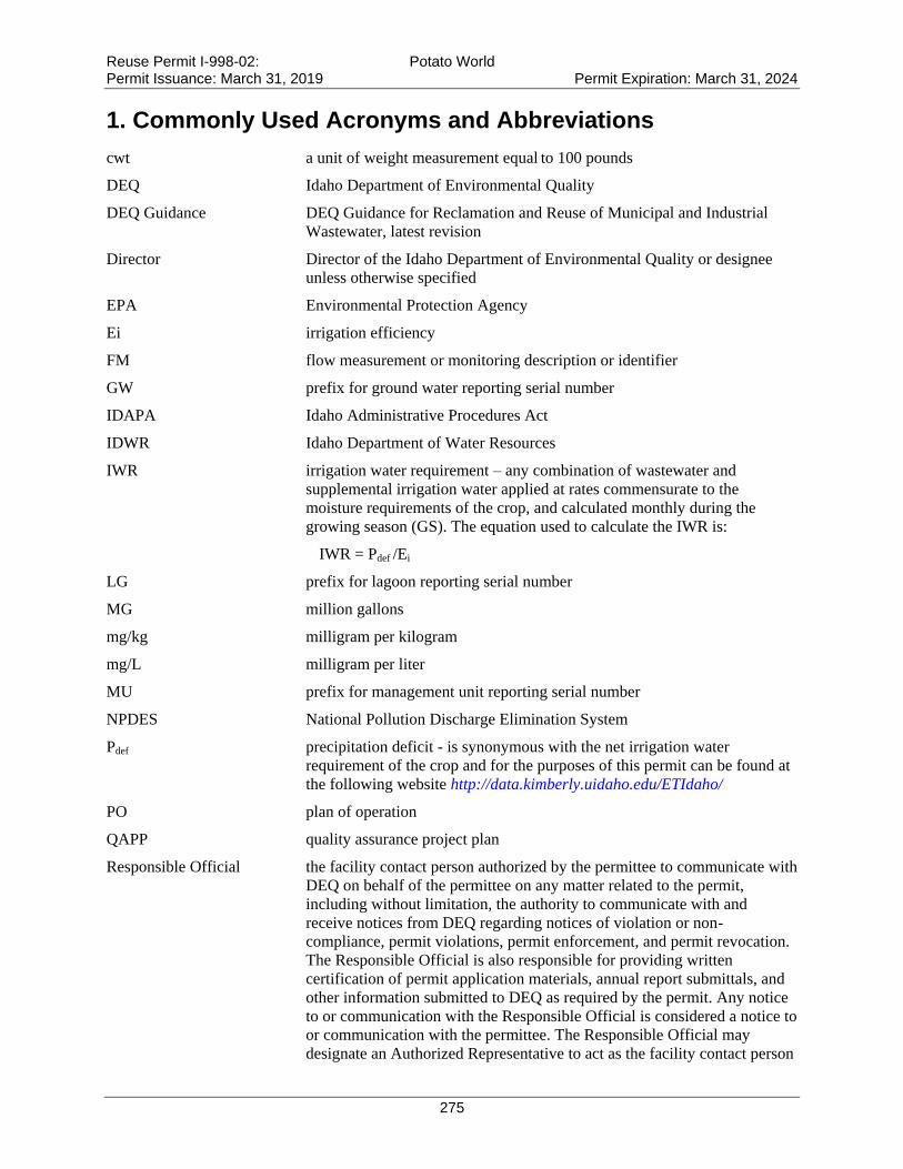
Reuse Permit I-998-02: Potato World Permit Issuance: March 31, 2019 Permit Expiration: March 31, 2024
275
1. Commonly Used Acronyms and Abbreviations
cwt a unit of weight measurement equal to 100 pounds
DEQ Idaho Department of Environmental Quality
DEQ Guidance DEQ Guidance for Reclamation and Reuse of Municipal and Industrial
Wastewater, latest revision
Director Director of the Idaho Department of Environmental Quality or designee
unless otherwise specified
EPA Environmental Protection Agency
Ei irrigation efficiency
FM flow measurement or monitoring description or identifier
GW prefix for ground water reporting serial number
IDAPA Idaho Administrative Procedures Act
IDWR Idaho Department of Water Resources
IWR irrigation water requirement – any combination of wastewater and
supplemental irrigation water applied at rates commensurate to the
moisture requirements of the crop, and calculated monthly during the
growing season (GS). The equation used to calculate the IWR is:
IWR = Pdef /Ei
LG prefix for lagoon reporting serial number
MG million gallons
mg/kg milligram per kilogram
mg/L milligram per liter
MU prefix for management unit reporting serial number
NPDES National Pollution Discharge Elimination System
Pdef precipitation deficit - is synonymous with the net irrigation water
requirement of the crop and for the purposes of this permit can be found at
the following website http://data.kimberly.uidaho.edu/ETIdaho/
PO plan of operation
QAPP quality assurance project plan
Responsible Official the facility contact person authorized by the permittee to communicate with
DEQ on behalf of the permittee on any matter related to the permit,
including without limitation, the authority to communicate with and
receive notices from DEQ regarding notices of violation or non-
compliance, permit violations, permit enforcement, and permit revocation.
The Responsible Official is also responsible for providing written
certification of permit application materials, annual report submittals, and
other information submitted to DEQ as required by the permit. Any notice
to or communication with the Responsible Official is considered a notice to
or communication with the permittee. The Responsible Official may
designate an Authorized Representative to act as the facility contact person
Reuse Permit I-998-02: Potato World Permit Issuance: March 31, 2019 Permit Expiration: March 31, 2024
276
for any of the activities or duties related to the permit, except signing and
certifying the permit application, which must be done by the Responsible
Official. The Authorized Representative shall act as the Responsible
Official and shall bind the permittee as described in this definition.
Designation of the Authorized Representative shall follow the requirements
specified in Section 6.1.3 of the permit.
SU prefix for soil monitoring unit reporting serial number
SW prefix for supplemental irrigation water reporting serial number
WW prefix for wastewater reporting serial number
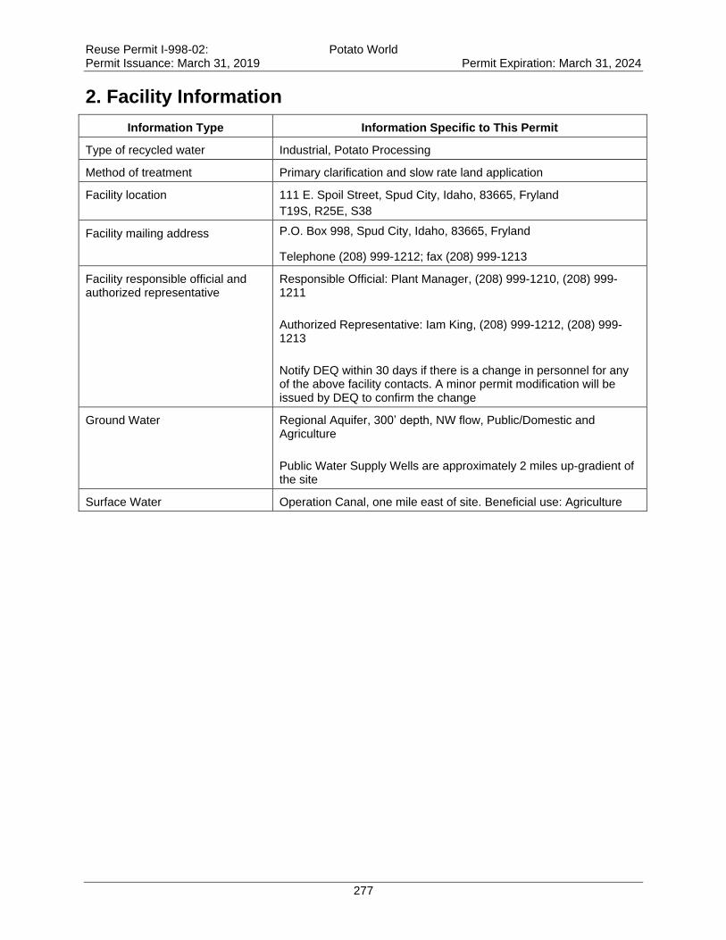
Reuse Permit I-998-02: Potato World Permit Issuance: March 31, 2019 Permit Expiration: March 31, 2024
277
2. Facility Information
Information Type Information Specific to This Permit
Type of recycled water Industrial, Potato Processing
Method of treatment Primary clarification and slow rate land application
Facility location 111 E. Spoil Street, Spud City, Idaho, 83665, Fryland
T19S, R25E, S38
Facility mailing address P.O. Box 998, Spud City, Idaho, 83665, Fryland
Telephone (208) 999-1212; fax (208) 999-1213
Facility responsible official and authorized representative
Responsible Official: Plant Manager, (208) 999-1210, (208) 999-1211
Authorized Representative: Iam King, (208) 999-1212, (208) 999-1213
Notify DEQ within 30 days if there is a change in personnel for any of the above facility contacts. A minor permit modification will be issued by DEQ to confirm the change
Ground Water Regional Aquifer, 300’ depth, NW flow, Public/Domestic and Agriculture
Public Water Supply Wells are approximately 2 miles up-gradient of the site
Surface Water Operation Canal, one mile east of site. Beneficial use: Agriculture
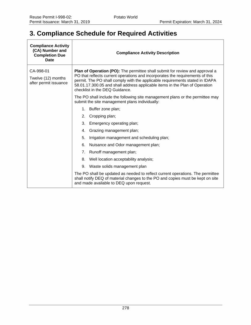
Reuse Permit I-998-02: Potato World Permit Issuance: March 31, 2019 Permit Expiration: March 31, 2024
278
3. Compliance Schedule for Required Activities
Compliance Activity (CA) Number and Completion Due
Date
Compliance Activity Description
CA-998-01
Twelve (12) months after permit issuance
Plan of Operation (PO): The permittee shall submit for review and approval a PO that reflects current operations and incorporates the requirements of this permit. The PO shall comply with the applicable requirements stated in IDAPA 58.01.17.300.05 and shall address applicable items in the Plan of Operation checklist in the DEQ Guidance.
The PO shall include the following site management plans or the permittee may submit the site management plans individually:
1. Buffer zone plan;
2. Cropping plan;
3. Emergency operating plan;
4. Grazing management plan;
5. Irrigation management and scheduling plan;
6. Nuisance and Odor management plan;
7. Runoff management plan;
8. Well location acceptability analysis;
9. Waste solids management plan
The PO shall be updated as needed to reflect current operations. The permittee shall notify DEQ of material changes to the PO and copies must be kept on site and made available to DEQ upon request.
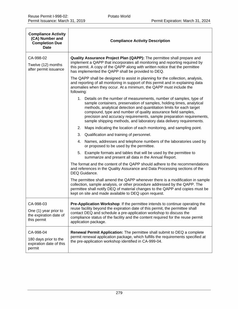
Reuse Permit I-998-02: Potato World Permit Issuance: March 31, 2019 Permit Expiration: March 31, 2024
279
Compliance Activity (CA) Number and Completion Due
Date
Compliance Activity Description
CA-998-02
Twelve (12) months after permit issuance
Quality Assurance Project Plan (QAPP): The permittee shall prepare and implement a QAPP that incorporates all monitoring and reporting required by this permit. A copy of the QAPP along with written notice that the permittee has implemented the QAPP shall be provided to DEQ.
The QAPP shall be designed to assist in planning for the collection, analysis, and reporting of all monitoring in support of this permit and in explaining data anomalies when they occur. At a minimum, the QAPP must include the following:
1. Details on the number of measurements, number of samples, type of sample containers, preservation of samples, holding times, analytical methods, analytical detection and quantitation limits for each target compound, type and number of quality assurance field samples, precision and accuracy requirements, sample preparation requirements, sample shipping methods, and laboratory data delivery requirements.
2. Maps indicating the location of each monitoring, and sampling point.
3. Qualification and training of personnel.
4. Names, addresses and telephone numbers of the laboratories used by or proposed to be used by the permittee.
5. Example formats and tables that will be used by the permittee to summarize and present all data in the Annual Report.
The format and the content of the QAPP should adhere to the recommendations and references in the Quality Assurance and Data Processing sections of the DEQ Guidance.
The permittee shall amend the QAPP whenever there is a modification in sample collection, sample analysis, or other procedure addressed by the QAPP. The permittee shall notify DEQ of material changes to the QAPP and copies must be kept on site and made available to DEQ upon request.
CA-998-03
One (1) year prior to the expiration date of this permit
Pre-Application Workshop: If the permittee intends to continue operating the reuse facility beyond the expiration date of this permit, the permittee shall contact DEQ and schedule a pre-application workshop to discuss the compliance status of the facility and the content required for the reuse permit application package.
CA-998-04
180 days prior to the expiration date of this permit
Renewal Permit Application: The permittee shall submit to DEQ a complete permit renewal application package, which fulfills the requirements specified at the pre-application workshop identified in CA-999-04.

Reuse Permit I-998-02: Potato World Permit Issuance: March 31, 2019 Permit Expiration: March 31, 2024
280
4. Permit Limits and Conditions
4.1 Hydraulic Management Unit Descriptions
Serial Number Description Irrigation System Type and
Irrigation Efficiency (Ei)
Maximum Acres
a
Allowed
MU-998-01 Thompson Field Wheel Line: (Ei = 0.75) 75
MU-998-02 Metcalf Field Solid Set: (Ei = 0.75) 50
MU-998-03 Pivot 1 Pivot: (Ei = 0.85) 150
MU-998-04 Pivot 2 Pivot: (Ei = 0.85) 150
Total acreage 400
a. Maximum acres represent the total permitted acreage of the MU as provided by the permittee. If the permittee uses less acreage in any season or year, then loading rates shall be presented and compliance shall be determined based on the actual acreage utilized during each season or year.
4.2 Hydraulic Loading Limits
Serial Number Growing Season Hydraulic Loading Nongrowing Season Maximum Hydraulic
Loading
MU-998-01
MU-998-02
Substantially at the irrigation water requirement (IWR)
a
Not allowed
MU-998-03
MU-998-04
Substantially at the irrigation water requirement (IWR)
a
November: 1.0 inches; 4.07 MG
December: 0.8 inches; 3.26 MG
January: 0.75 inches; 3.05 MG
February: 0.75 inches; 3.05 MG
March: 1.5 inches; 6.11 MG
a. For compliance purposes, the source of Pdef data used to calculate the IWR shall be specified in the PO.
4.3 Constituent Loading Limits
Serial Number
Constituent Loading (from all sources)
Nitrogen (lb/acre)
Salt (NVDS) (lb/acre)
COD growing season
(lb/acre-day)a
COD nongrowing season
(lb/acre-day)a
MU-998-01
MU-998-02
150% of typical crop uptake
b
None 50 None
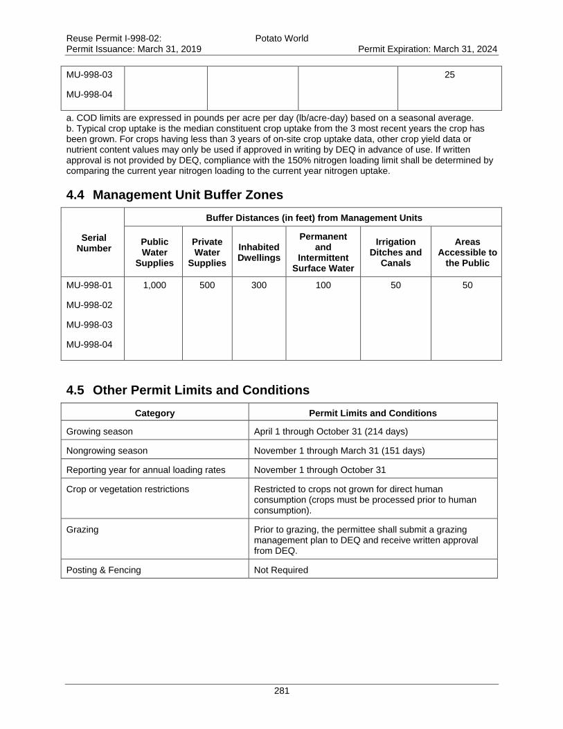
Reuse Permit I-998-02: Potato World Permit Issuance: March 31, 2019 Permit Expiration: March 31, 2024
281
MU-998-03
MU-998-04
25
a. COD limits are expressed in pounds per acre per day (lb/acre-day) based on a seasonal average. b. Typical crop uptake is the median constituent crop uptake from the 3 most recent years the crop has been grown. For crops having less than 3 years of on-site crop uptake data, other crop yield data or nutrient content values may only be used if approved in writing by DEQ in advance of use. If written approval is not provided by DEQ, compliance with the 150% nitrogen loading limit shall be determined by comparing the current year nitrogen loading to the current year nitrogen uptake.
4.4 Management Unit Buffer Zones
Serial Number
Buffer Distances (in feet) from Management Units
Public Water
Supplies
Private Water
Supplies
Inhabited Dwellings
Permanent and
Intermittent Surface Water
Irrigation Ditches and
Canals
Areas Accessible to
the Public
MU-998-01
MU-998-02
MU-998-03
MU-998-04
1,000 500 300 100 50 50
4.5 Other Permit Limits and Conditions
Category Permit Limits and Conditions
Growing season April 1 through October 31 (214 days)
Nongrowing season November 1 through March 31 (151 days)
Reporting year for annual loading rates November 1 through October 31
Crop or vegetation restrictions Restricted to crops not grown for direct human consumption (crops must be processed prior to human consumption).
Grazing Prior to grazing, the permittee shall submit a grazing management plan to DEQ and receive written approval from DEQ.
Posting & Fencing Not Required
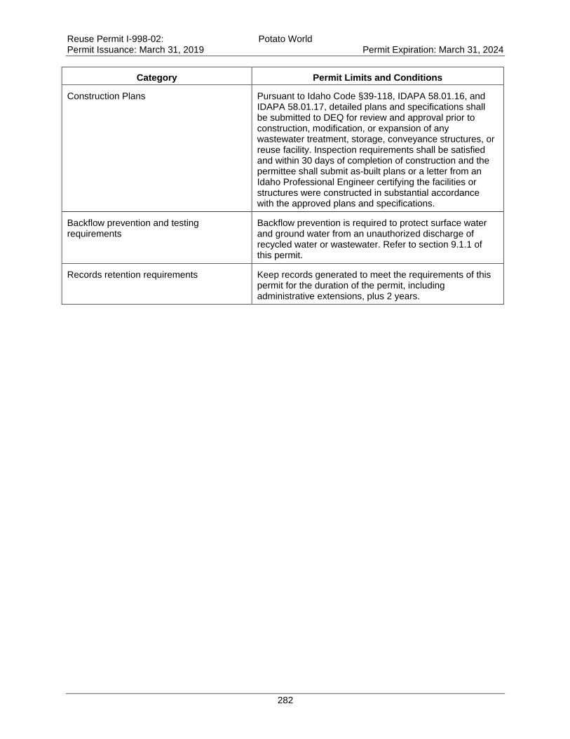
Reuse Permit I-998-02: Potato World Permit Issuance: March 31, 2019 Permit Expiration: March 31, 2024
282
Category Permit Limits and Conditions
Construction Plans
Pursuant to Idaho Code §39-118, IDAPA 58.01.16, and IDAPA 58.01.17, detailed plans and specifications shall be submitted to DEQ for review and approval prior to construction, modification, or expansion of any wastewater treatment, storage, conveyance structures, or reuse facility. Inspection requirements shall be satisfied and within 30 days of completion of construction and the permittee shall submit as-built plans or a letter from an Idaho Professional Engineer certifying the facilities or structures were constructed in substantial accordance with the approved plans and specifications.
Backflow prevention and testing requirements
Backflow prevention is required to protect surface water and ground water from an unauthorized discharge of recycled water or wastewater. Refer to section 9.1.1 of this permit.
Records retention requirements Keep records generated to meet the requirements of this permit for the duration of the permit, including administrative extensions, plus 2 years.
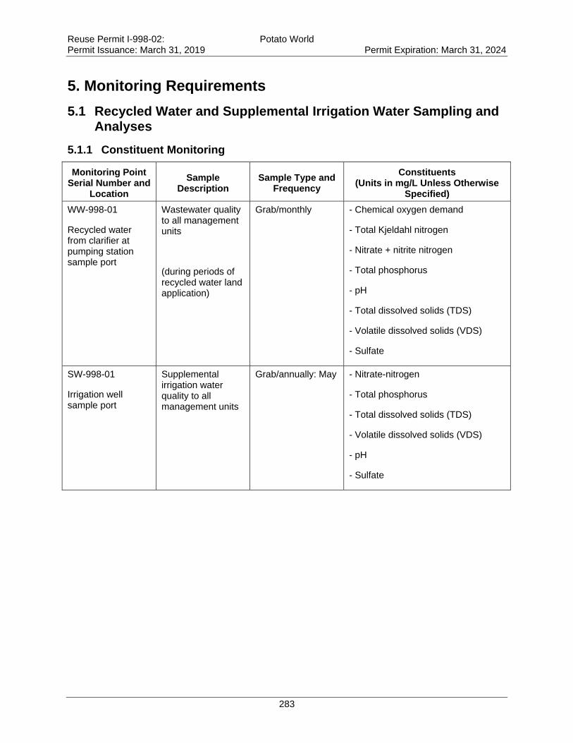
Reuse Permit I-998-02: Potato World Permit Issuance: March 31, 2019 Permit Expiration: March 31, 2024
283
5. Monitoring Requirements
5.1 Recycled Water and Supplemental Irrigation Water Sampling and Analyses
5.1.1 Constituent Monitoring
Monitoring Point Serial Number and
Location
Sample Description
Sample Type and Frequency
Constituents (Units in mg/L Unless Otherwise
Specified)
WW-998-01
Recycled water from clarifier at pumping station sample port
Wastewater quality to all management units
(during periods of recycled water land application)
Grab/monthly
- Chemical oxygen demand
- Total Kjeldahl nitrogen
- Nitrate + nitrite nitrogen
- Total phosphorus
- pH
- Total dissolved solids (TDS)
- Volatile dissolved solids (VDS)
- Sulfate
SW-998-01
Irrigation well sample port
Supplemental irrigation water quality to all management units
Grab/annually: May - Nitrate-nitrogen
- Total phosphorus
- Total dissolved solids (TDS)
- Volatile dissolved solids (VDS)
- pH
- Sulfate
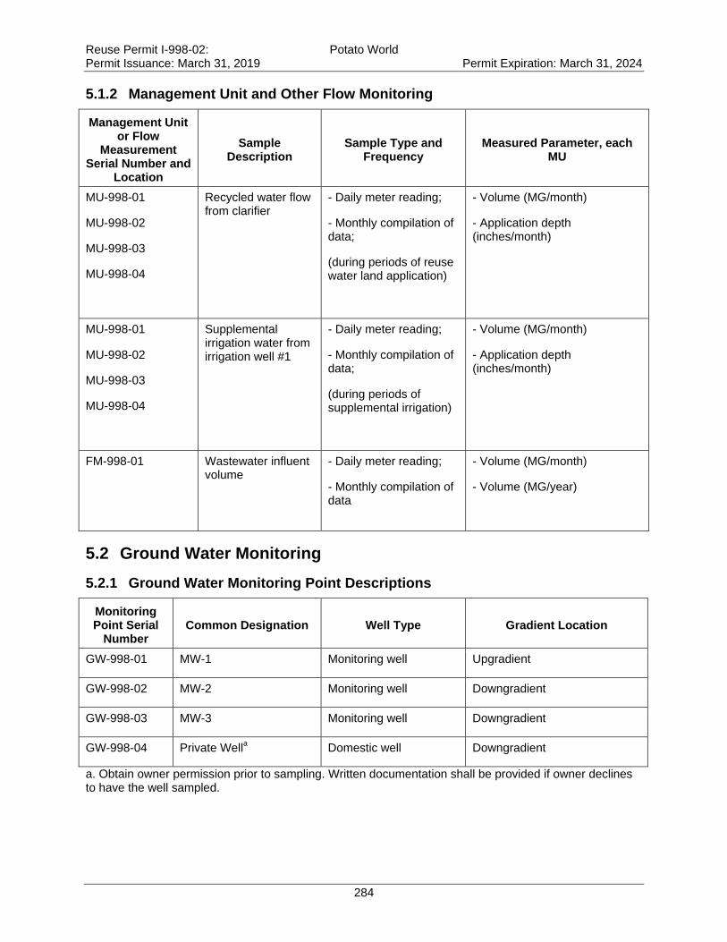
Reuse Permit I-998-02: Potato World Permit Issuance: March 31, 2019 Permit Expiration: March 31, 2024
284
5.1.2 Management Unit and Other Flow Monitoring
Management Unit or Flow
Measurement Serial Number and
Location
Sample Description
Sample Type and Frequency
Measured Parameter, each MU
MU-998-01
MU-998-02
MU-998-03
MU-998-04
Recycled water flow from clarifier
- Daily meter reading;
- Monthly compilation of data;
(during periods of reuse water land application)
- Volume (MG/month)
- Application depth (inches/month)
MU-998-01
MU-998-02
MU-998-03
MU-998-04
Supplemental irrigation water from irrigation well #1
- Daily meter reading;
- Monthly compilation of data;
(during periods of supplemental irrigation)
- Volume (MG/month)
- Application depth (inches/month)
FM-998-01
Wastewater influent volume
- Daily meter reading;
- Monthly compilation of data
- Volume (MG/month)
- Volume (MG/year)
5.2 Ground Water Monitoring
5.2.1 Ground Water Monitoring Point Descriptions
Monitoring Point Serial
Number Common Designation Well Type Gradient Location
GW-998-01 MW-1 Monitoring well Upgradient
GW-998-02 MW-2 Monitoring well Downgradient
GW-998-03 MW-3 Monitoring well Downgradient
GW-998-04 Private Wella Domestic well Downgradient
a. Obtain owner permission prior to sampling. Written documentation shall be provided if owner declines to have the well sampled.
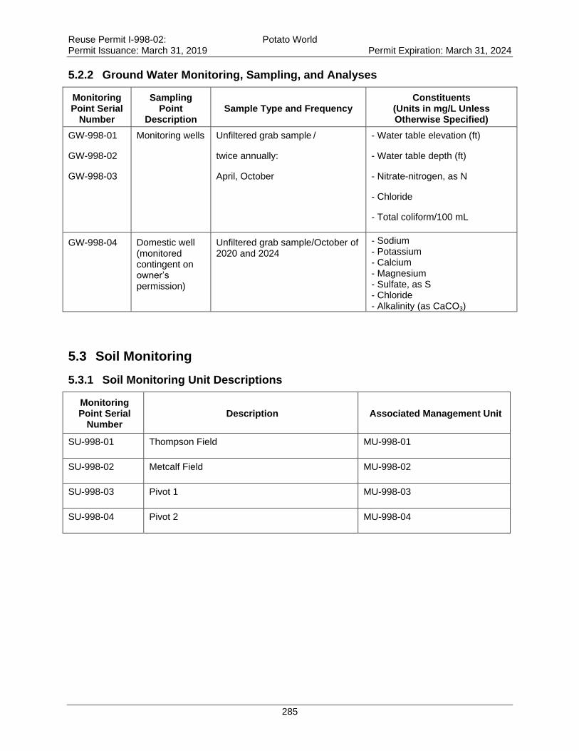
Reuse Permit I-998-02: Potato World Permit Issuance: March 31, 2019 Permit Expiration: March 31, 2024
285
5.2.2 Ground Water Monitoring, Sampling, and Analyses
Monitoring Point Serial
Number
Sampling Point
Description Sample Type and Frequency
Constituents (Units in mg/L Unless Otherwise Specified)
GW-998-01
GW-998-02
GW-998-03
Monitoring wells Unfiltered grab sample /
twice annually:
April, October
- Water table elevation (ft)
- Water table depth (ft)
- Nitrate-nitrogen, as N
- Chloride
- Total coliform/100 mL
GW-998-04 Domestic well (monitored contingent on owner’s permission)
Unfiltered grab sample/October of 2020 and 2024
- Sodium - Potassium - Calcium - Magnesium - Sulfate, as S - Chloride - Alkalinity (as CaCO3)
5.3 Soil Monitoring
5.3.1 Soil Monitoring Unit Descriptions
Monitoring Point Serial
Number Description Associated Management Unit
SU-998-01 Thompson Field MU-998-01
SU-998-02 Metcalf Field MU-998-02
SU-998-03 Pivot 1 MU-998-03
SU-998-04 Pivot 2 MU-998-04
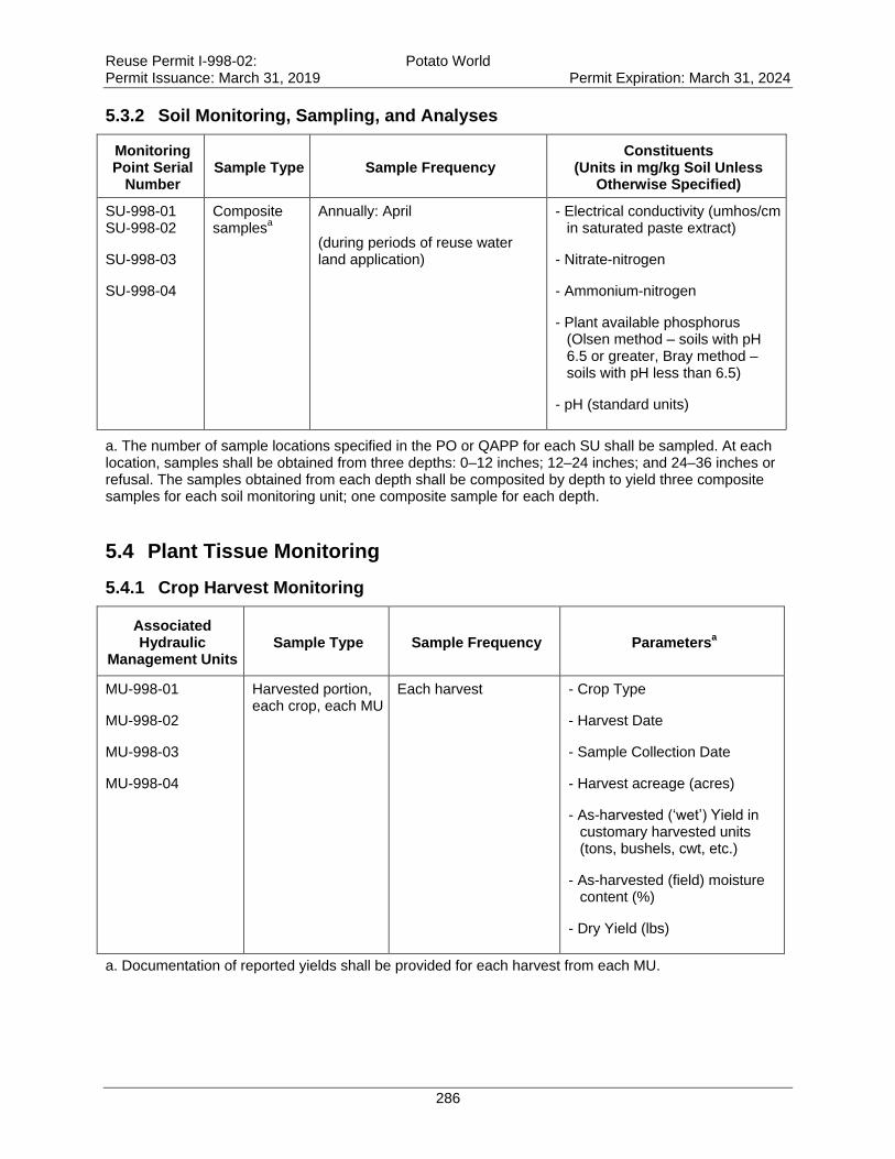
Reuse Permit I-998-02: Potato World Permit Issuance: March 31, 2019 Permit Expiration: March 31, 2024
286
5.3.2 Soil Monitoring, Sampling, and Analyses
Monitoring Point Serial
Number Sample Type Sample Frequency
Constituents (Units in mg/kg Soil Unless
Otherwise Specified)
SU-998-01 SU-998-02
SU-998-03
SU-998-04
Composite samples
a
Annually: April
(during periods of reuse water land application)
- Electrical conductivity (umhos/cm in saturated paste extract)
- Nitrate-nitrogen
- Ammonium-nitrogen
- Plant available phosphorus (Olsen method – soils with pH 6.5 or greater, Bray method – soils with pH less than 6.5)
- pH (standard units)
a. The number of sample locations specified in the PO or QAPP for each SU shall be sampled. At each location, samples shall be obtained from three depths: 0–12 inches; 12–24 inches; and 24–36 inches or refusal. The samples obtained from each depth shall be composited by depth to yield three composite samples for each soil monitoring unit; one composite sample for each depth.
5.4 Plant Tissue Monitoring
5.4.1 Crop Harvest Monitoring
Associated Hydraulic
Management Units Sample Type Sample Frequency Parameters
a
MU-998-01
MU-998-02
MU-998-03
MU-998-04
Harvested portion, each crop, each MU
Each harvest
- Crop Type
- Harvest Date
- Sample Collection Date
- Harvest acreage (acres)
- As-harvested (‘wet’) Yield in customary harvested units (tons, bushels, cwt, etc.)
- As-harvested (field) moisture content (%)
- Dry Yield (lbs)
a. Documentation of reported yields shall be provided for each harvest from each MU.
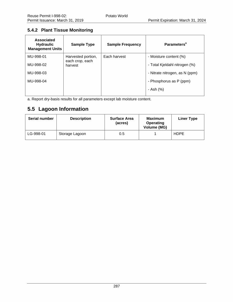
Reuse Permit I-998-02: Potato World Permit Issuance: March 31, 2019 Permit Expiration: March 31, 2024
287
5.4.2 Plant Tissue Monitoring
Associated Hydraulic
Management Units Sample Type Sample Frequency Parameters
a
MU-998-01
MU-998-02
MU-998-03
MU-998-04
Harvested portion, each crop, each harvest
Each harvest
- Moisture content (%)
- Total Kjeldahl nitrogen (%)
- Nitrate nitrogen, as N (ppm)
- Phosphorus as P (ppm)
- Ash (%)
a. Report dry-basis results for all parameters except lab moisture content.
5.5 Lagoon Information
Serial number Description Surface Area (acres)
Maximum Operating
Volume (MG)
Liner Type
LG-998-01 Storage Lagoon 0.5 1 HDPE

Reuse Permit I-998-02: Potato World Permit Issuance: March 31, 2019 Permit Expiration: March 31, 2024
288
6. Reporting Requirements
6.1 Annual Report Requirements
The permittee shall submit to DEQ an Annual Report prepared by a competent environmental
professional covering the previous reporting year.
6.1.1 Due Date
The Annual Report is due no later than January 31 of each year, which shall cover the previous
reporting year.
6.1.2 Required Contents
The Annual Report shall include the following:
1. A brief interpretive discussion of all required monitoring data. The discussion shall
address data quality objectives, validation, and verification; permit compliance; and
reuse facility environmental impacts. The reporting year for this permit is specified in
section 4.5.
2. Results of the required monitoring as described in section 5 of this permit. If the
permittee monitors any parameter for compliance purposes more frequently than
required by this permit, the results of this monitoring shall be included in the
calculation and reporting of the data submitted in the Annual Report. The report shall
present all monitoring data in organized data summary tables to expedite review.
3. Status of all work described in section 3 of this permit.
4. Results of all backflow testing, repairs, and replacements required by Section 9.1.1 of
this permit.
5. Discussion of major maintenance activities such as major equipment replacement,
liner maintenance, and wastewater treatment and reuse facility maintenance.
6. A summary of all noncompliance events that occurred during the reporting year.
Examples of noncompliance events that must be discussed include, but are not limited
to: complaints, missed monitoring events, incorrect monitoring dates or frequencies,
dry monitoring wells, uncontained spills causing runoff, construction without DEQ
engineering plan approval, construction without engineering inspection, and reporting
incorrect acreage.
7. Submittal of the calculations and observations for hydraulic management units
specified in the table below.
8. All laboratory analytical reports, chain of custody forms, and crop yield
documentation.
9. The parameters in the following table:
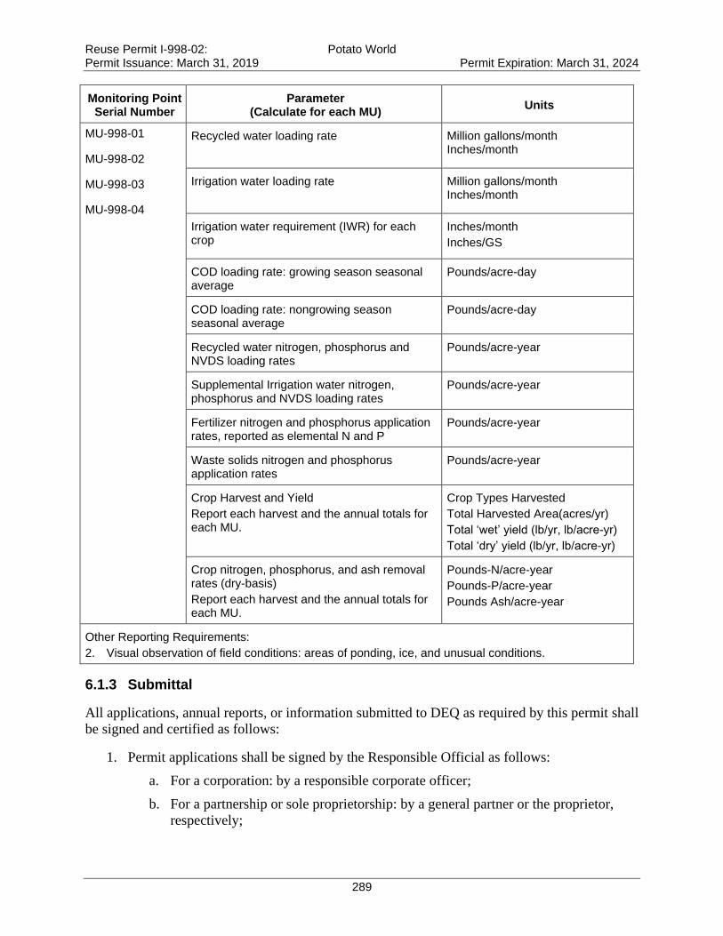
Reuse Permit I-998-02: Potato World Permit Issuance: March 31, 2019 Permit Expiration: March 31, 2024
289
Monitoring Point Serial Number
Parameter (Calculate for each MU)
Units
MU-998-01
MU-998-02
MU-998-03
MU-998-04
Recycled water loading rate Million gallons/month Inches/month
Irrigation water loading rate Million gallons/month Inches/month
Irrigation water requirement (IWR) for each crop
Inches/month
Inches/GS
COD loading rate: growing season seasonal average
Pounds/acre-day
COD loading rate: nongrowing season seasonal average
Pounds/acre-day
Recycled water nitrogen, phosphorus and NVDS loading rates
Pounds/acre-year
Supplemental Irrigation water nitrogen, phosphorus and NVDS loading rates
Pounds/acre-year
Fertilizer nitrogen and phosphorus application rates, reported as elemental N and P
Pounds/acre-year
Waste solids nitrogen and phosphorus application rates
Pounds/acre-year
Crop Harvest and Yield
Report each harvest and the annual totals for each MU.
Crop Types Harvested
Total Harvested Area(acres/yr)
Total ‘wet’ yield (lb/yr, lb/acre-yr)
Total ‘dry’ yield (lb/yr, lb/acre-yr)
Crop nitrogen, phosphorus, and ash removal rates (dry-basis)
Report each harvest and the annual totals for each MU.
Pounds-N/acre-year
Pounds-P/acre-year
Pounds Ash/acre-year
Other Reporting Requirements:
2. Visual observation of field conditions: areas of ponding, ice, and unusual conditions.
6.1.3 Submittal
All applications, annual reports, or information submitted to DEQ as required by this permit shall
be signed and certified as follows:
1. Permit applications shall be signed by the Responsible Official as follows:
a. For a corporation: by a responsible corporate officer;
b. For a partnership or sole proprietorship: by a general partner or the proprietor,
respectively;
Reuse Permit I-998-02: Potato World Permit Issuance: March 31, 2019 Permit Expiration: March 31, 2024
290
c. For a municipality, state, federal, Indian tribe, or other public agency: by either
the principal executive officer or ranking elected official.
2. Annual reports and other information requested by DEQ shall be signed by the
Responsible Official or by a duly Authorized Representative of that person. A person is a
duly Authorized Representative only if:
a. The authorization is made in writing by the responsible official;
b. The authorization specifies either an individual or position having responsibility
for the overall operation or the regulated facility, such as the position of plant
manager, superintendent, position of equivalent responsibility, or an individual
having overall responsibility for environmental matters for the company; and
c. The written authorization is submitted to DEQ.
Submit the annual report to the following DEQ regional office at this address:
Engineering Manager
Idaho Department of Environmental Quality
Boise Regional Office
1445 N. Orchard
Boise, ID 83706
The annual report shall include the following certification statement and be signed, dated, and
certified by the permittee’s Responsible Official or Authorized Representative:
“I certify that the information in this submittal was prepared in conformance with the
Quality Assurance Project Plan required by permit M-998-02, and is to the best of my
knowledge, true, accurate and complete and I acknowledge that knowing submission of
false or incomplete information may result in permit revocation as provided for in
IDAPA 58.01.17.920.01 or other enforcement action as provided for under Idaho law.”
6.2 Emergency and Noncompliance Reporting
Report noncompliance incidents to DEQ’s regional office at (208) 373-0550 or 1-888-800-3480.
In case of emergencies, call the emergency 24-hour number at 1-800-632-8000 and DEQ’s
regional office.
See Section 8, “Standard Permit Conditions,” and IDAPA 58.01.17.500.06 for reporting
requirements for facilities.
All instances of unpermitted discharges of wastewater to Surface Waters of the United States
shall also be reported to the Environmental Protection Agency by telephone within 24 hours
from the time the permittee becomes aware of the discharge and in writing within five days at
this address:
NPDES/Stormwater Coordinator, USEPA Idaho Operations Office
950 W. Bannock, Suite 900
Boise, ID 83702
208-378-5746 / 208-378-5744 and EPA Hot Line (206) 553-1846
Reuse Permit I-998-02: Potato World Permit Issuance: March 31, 2019 Permit Expiration: March 31, 2024
291
7. Permit for Use of Industrial Recycled Water
The following are permit requirements for industrial recycled water and are included as terms of
this permit as required by the “Recycled Water Rules,” (IDAPA 58.01.17.616).
616. PERMIT FOR USE OF INDUSTRIAL RECYCLED WATER.
Industrial recycled water shall only be used in accordance with a permit issued pursuant to these rules. Permit
conditions and limitations shall be developed by the Department on a case-by-case basis taking into account the
specific characteristics of the wastewater to be recycled, the treatment necessary to ensure the use of such recycled
water is in compliance with IDAPA 58.01.11, “Ground Water Quality Rule” and IDAPA 58.01.02, “Water Quality
Standards.” Unless otherwise indicated in this section, the permit application, processing and issuance procedures
provided in this rule shall apply to industrial reuse permits. (4-7-11)
8. Standard Permit Conditions
The following standard permit conditions are included as terms of this permit as required by the
“Recycled Water Rules,” (IDAPA 58.01.17.500).
500. STANDARD PERMIT CONDITIONS.
The following conditions shall apply to and be included in all permits. (4-1-88)
01. Compliance Required. The permittee shall comply with all conditions of the permit. (4-1-88)
02. Renewal Responsibilities. If the permittee intends to continue operation of the permitted facility after the
expiration of an existing permit, the permittee shall apply for a new permit in accordance with
these rules. (4-1-88)
03. Operation of Facilities. The permittee shall at all times properly maintain and operate all structures,
systems, and equipment for treatment, control and monitoring, which are installed or used by the permittee to
achieve compliance with the permit or these rules. (4-1-88)
04. Provide Information. The permittee shall furnish to the Director within a reasonable time, any information
including copies of records, which may be requested by the Director to determine whether cause exists for
modifying, revoking, re-issuing, or terminating the permit, or to determine compliance with the permit or these
rules. (4-1-88)
05. Entry and Access. The permittee shall allow the Director, consistent with Title 39, Chapter 1, Idaho Code,
to: (4-1-88)
a. Enter the permitted facility. (4-1-88)
b. Inspect any records that must be kept under the conditions of the permit. (4-1-88)
c. Inspect any facility, equipment, practice, or operation permitted or required by the permit. (4-1-88)
d. Sample or monitor for the purpose of assuring permit compliance, any substance or any parameter at the
facility. (4-1-88)
06. Reporting. The permittee shall report to the Director under the circumstances and in the manner specified
in this section: (4-1-88)
a. In writing at least thirty (30) days before any planned physical alteration or addition to the permitted
facility or activity if that alteration or addition would result in any significant change in information that was
Reuse Permit I-998-02: Potato World Permit Issuance: March 31, 2019 Permit Expiration: March 31, 2024
292
submitted during the permit application process. When the alteration or addition results in a need for a major
modification, such alteration or addition shall not be made prior to Department approval issued in accordance with
these rules. (4-7-11)
b. In writing thirty (30) days before any anticipated change which would result in noncompliance with any
permit condition or these rules. (4-1-88)
c. Orally within twenty-four (24) hours from the time the permittee became aware of any noncompliance
which may endanger the public health or the environment at telephone numbers provided in the permit by the
Director. (4-1-88)
d. In writing as soon as possible but within five (5) days of the date the permittee knows or should know of
any noncompliance unless extended by the Department. This report shall contain: (4-1-88)
i. A description of the noncompliance and its cause; (4-1-88)
ii. The period of noncompliance including to the extent possible, times and dates and, if the noncompliance
has not been corrected, the anticipated length of time it is expected to continue; and (4-7-11)
iii. Steps taken or planned, including timelines, to reduce or eliminate the continuance or reoccurrence of the
noncompliance. (4-7-11)
e. In writing as soon as possible after the permittee becomes aware of relevant facts not submitted or incorrect
information submitted, in a permit application or any report to the Director. Those facts or the correct information
shall be included as a part of this report. (4-1-88)
07. Minimize Impacts. The permittee shall take all necessary actions to eliminate and correct any adverse
impact on the public health or the environment resulting from permit noncompliance. (4-1-88)
08. Compliance with “Ground Water Quality Rule.” Permits issued pursuant to these rules shall require
compliance with IDAPA 58.01.11, “Ground Water Quality Rule.” (4-7-11)

Reuse Permit I-998-02: Potato World Permit Issuance: March 31, 2019 Permit Expiration: March 31, 2024
293
9. General Permit Conditions
The following general permit conditions are based on the cited rules at the time of issuance and
are enforceable as part of this permit. Note that the rules cited in this section, and elsewhere in
this permit, are supplemented by the rules themselves. Rules applicable to your facility are
enforceable whether or not they appear in this permit.
9.1 Operations
9.1.1 Backflow Prevention
Reuse facilities with existing or planned cross-connections or interconnections between the
recycled water system and any water supply (potable or nonpotable), or surface water, shall have
backflow prevention assemblies, devices, or methods as required by the applicable rule or as
specified in this permit and approved by DEQ.
For public water systems, backflow assemblies shall meet the requirements of IDAPA
58.01.08.543. Assemblies shall be adequately maintained and shall be tested annually by a
certified backflow assembly tester, and repaired or replaced as necessary to maintain operational
status.
For domestic water supply wells, backflow prevention devices shall meet the requirements of
IDAPA 07.02.04 and shall be adequately operated and maintained.
Irrigation water supply wells shall meet the requirements of IDAPA 37.03.09.36 for preventing
any waste or contamination of the ground water resource. Backflow prevention assemblies or
devices used to protect the ground water shall be adequately operated and maintained.
Discharge of recycled water to surface water is regulated by the EPA NPDES program. An
NPDES permit is required for any discharge to surface water and backflow prevention shall be
implemented to prevent any unauthorized discharge. Backflow prevention assemblies or devices
used to protect the ground water shall be adequately operated and maintained.
Records of all testable backflow assembly test results, repairs, and replacements shall be kept at
the reuse facility along with other operational records, and shall be discussed in the Annual
Report and made available for inspection by DEQ. Other approved means of backflow
prevention, such as siphons and air-gap structures that cannot be tested, shall be maintained in
operable order.
9.1.2 Restricted to Premises
Wastewaters or recharge waters applied to the land surface must be restricted to the premises of
the application site. Wastewater discharges to surface water that require a permit under the Clean
Water Act must be authorized by the United States Environmental Protection Agency
(IDAPA 58.01.16.600.02).
9.1.3 Health Hazards, Nuisances, and Odors Prohibited
Health hazards, nuisances, and odors are prohibited as follows:
Reuse Permit I-998-02: Potato World Permit Issuance: March 31, 2019 Permit Expiration: March 31, 2024
294
Wastewater must not create a public health hazard or nuisance condition
(IDAPA 58.01.16.600.03).
No person shall allow, suffer, cause or permit the emission of odorous gases, liquids, or
solids into the atmosphere in such quantities as to cause air pollution
(IDAPA 58.01.01.776.01).
Air Pollution. The presence in the outdoor atmosphere of any air pollutant or combination
thereof in such quantity of such nature and duration and under such conditions as would
be injurious to human health or welfare, to animal or plant life, or to property, or to
interfere unreasonably with the enjoyment of life or property (IDAPA 58.01.01.006.06).
9.1.4 Solids Management
Biosolids are the nutrient-rich organic materials resulting from the treatment of sewage sludge.
When treated and processed, sewage sludge becomes biosolids which can be safely recycled and
applied as fertilizer to sustainably improve and maintain productive soils and stimulate plant
growth.
Biosolids generated from sewage sludge are regulated by EPA under 40 CFR Part 503 and
require a DEQ approved sludge disposal plan as outlined in IDAPA 58.01.16.650. Contact DEQ
prior to application of biosolids at any permitted reuse facility.
Sludge is the semi-liquid mass produced and removed by wastewater treatment processes. This
does not include grit, garbage, and large solids.
Sludge is generated by wastewater treatment processes at municipal and industrial facilities.
Solid Waste is any garbage or refuse, sludge from a waste water treatment plant, water supply
treatment plant, or air pollution control facility and other discarded material including solid,
liquid, semi-solid, or contained gaseous material resulting from industrial, commercial, mining,
and agricultural operations and from community activities, but does not include solid or
dissolved materials in domestic sewage, or solid or dissolved material in irrigation return flows
or industrial discharges which are point sources subject to permits under Section 402 of the
Federal Water Pollution Control Act, as amended or source, special nuclear, or by-product
material as defined by the Atomic Energy Act of 1954, as amended.
Solid waste does not include inert wastes, manures and crop residues ultimately returned to the
soils at agronomic rates, and any agricultural solid waste which is managed and regulated
pursuant to rules adopted by the Idaho Department of Agriculture. DEQ reserves the right to use
existing authorities to regulate agricultural waste that impacts human health or the environment.
Solid waste is regulated under “Solid Waste Management Rules”, IDAPA 58.01.06. Wastes
otherwise regulated by DEQ (i.e. this permit) are not regulated under 58.01.06.
Waste Solids include sludge and wastes otherwise regulated by DEQ in accordance with IDAPA
58.01.06.001.03.a.xii. Waste solids may include vegetative waste, silt and mud containing
organic matter, and other non-inert solid wastes.
Inert wastes are defined as non-combustible, nonhazardous, and non-putrescible solids wastes
that are likely to retain their physical and chemical structure and have a de minimis potential to
Reuse Permit I-998-02: Potato World Permit Issuance: March 31, 2019 Permit Expiration: March 31, 2024
295
generate leachate under expected conditions of disposal, which includes resistance to biological
attack.
Waste solids require a DEQ approved sludge disposal plan as outlined in IDAPA 58.01.16.650.
9.1.5 Temporary Cessation of Operations and Closure (IDAPA 58.01.17.801)
Temporary cessation of operations and closure must be addressed as follows:
01. Temporary Cessation. A permittee shall implement any applicable conditions specified in the permit for
temporary cessation of operations. When the permit does not specify applicable temporary cessation conditions, the
permittee shall notify the Director prior to a temporary cessation of operations at the facility greater than sixty (60)
days in duration and any cessation not for regular maintenance or repair. Cessation of operations necessary for
regular maintenance or repair of a duration of sixty (60) days or less are not required to notify the Department under
this section. All notifications required under this section shall include a proposed temporary cessation plan that will
ensure the cessation of operations will not pose a threat to human health or the environment. (4-7-11)
02. Closure. A closure plan shall be required when a facility is closed voluntarily and when a permit is revoked
or expires. A permittee shall implement any applicable conditions specified in the permit for closure of the facility.
Unless otherwise directed by the terms of the permit or by the Director, the permittee shall submit a closure plan to
the Director for approval at least ninety (90) days prior to ceasing operations. The closure plan shall ensure that the
closed facility will not pose a threat to human health and the environment. Closure plan approval may be
conditioned upon a permittee’s agreement to complete such site investigations, monitoring, and any necessary
remediation activities that may be required. (4-7-11)
9.1.6 Plan of Operation (IDAPA 58.01.17.300.05)
The PO must comply with the following:
05. Reuse Facility Operation and Maintenance Manual or Plan of Operations. A facility’s operation and
maintenance manual must contain all system components relating to the reuse facility in order to comply with
IDAPA 58.01.16 “Wastewater Rules,” Section 425. Manuals and manual amendments are subject to the review and
approval provision therein. In addition to the content required by IDAPA 58.01.16.425, manuals for reuse facilities
shall include, if applicable: operation and management responsibility, permits and standards, general plant
description, operation and control of unit operations, land application site maps, wastewater characterization,
cropping plan, hydraulic loading rate, constituent loading rates, compliance activities, seepage rate testing, site
management plans, monitoring, site operations and maintenance, solids handling and processing, laboratory testing,
general maintenance, records and reports, store room and inventory, personnel, an emergency operating plan, and
any other information required by the Department. (4-7-11)
9.1.7 Reserved
9.1.8 Ground Water Quality (IDAPA 58.01.11)
The permittee shall comply with the requirements of “Ground Water Quality Rule”
(IDAPA 58.01.11).
9.2 Administrative
Requirements for administration of the permit are defined as follows.
9.2.1 Permit Modification (IDAPA 58.01.17.700)
01. Modification of Permits. A permit modification may be initiated by the receipt of a request for
modification from the permittee, or may be initiated by the Department if one (1) of more of the following causes

Reuse Permit I-998-02: Potato World Permit Issuance: March 31, 2019 Permit Expiration: March 31, 2024
296
for modification exist: (4-7-11)
a. Alterations. There are material and substantial alterations or additions to the permitted facility or activity
which occurred after permit issuance which justify the application of permit conditions that are different or absent in
the existing permit. (4-7-11)
b. New standards or regulations. The standards or regulations on which the permit was based have been
changed by promulgation of amended standards or regulations or by judicial decision after the permit was issued.
(4-7-11)
c. Compliance schedules. The Department determines good cause exists for modification of a compliance
schedule or terms and conditions of a permit. (4-7-11)
d. Non-limited pollutants. When the level of discharge of any pollutant which is not limited in the permit
exceeds the level which may cause an adverse impact to surface or ground waters. (4-7-11)
e. To correct technical mistakes, such as errors in calculation, or mistaken interpretations of law made in
determining permit conditions. (4-7-11)
f. When a treatment technology proposed, installed, and properly operated and maintained by the permittee
fails to achieve the requirements of the permit. (4-7-11)
9.2.2 Permit Transferable (IDAPA 58.01.17.800)
01. General. A permit may be transferred only upon approval of the Department. No transfer is required for a
corporate name change as long as the secretary of state can verify that a change in name alone has occurred. An
attempted transfer is not effective for any purpose until approved in writing by the Department. (4-7-11)
9.2.3 Permit Revocation (IDAPA 58.01.17.920)
01. Conditions for Revocation. The Director may revoke a permit if the permittee violates any permit
condition or these rules, or the Director becomes aware of any omission or misrepresentation of condition or
information relied upon when issuing the permit. (4-7-11)
02. Notice of Revocation. Except in cases of emergency, the Director shall issue a written notice of intent to
revoke to the permittee prior to final revocation. Revocation shall become final within thirty-five (35) days of
receipt of the notice by the permittee, unless within that time the permittee requests an administrative hearing in
writing. The hearing shall be conducted in accordance with IDAPA 58.01.23, Rules of Administrative Procedure
Before the Board of Environmental Quality.” (5-3-03)
03. Emergency Action. If the Director finds the public health, safety or welfare requires emergency action, the
Director shall incorporate findings in support of such action in a written notice of emergency revocation issued to
the permittee. Emergency revocation shall be effective upon receipt by the permittee. Thereafter, if requested by the
permittee in writing, the Director shall provide the permittee a revocation hearing and prior notice thereof. Such
hearings shall be conducted in accordance with IDAPA 58.01.23, Rules of Administrative Procedure Before the
Board of Environmental Quality.” (3-15-02)
04. Revocation and Closure. A permittee shall perform the closure requirements in a permit, the closure
requirements of these rules, and complete all closure plan activities notwithstanding the revocation of the permit.
(4-7-11)
9.2.4 Violations (IDAPA 58.01.17.930)
Any person violating any provision of these rules or any permit or order issued thereunder shall be liable for a civil
penalty not to exceed ten thousand dollars ($10,000) or one thousand dollars ($1,000) for each day of a continuing
violation, whichever is greater. In addition, pursuant to Title 39, Chapter 1, Idaho Code, any willful or negligent
violation may constitute a misdemeanor. (4-1-88)
Reuse Permit I-998-02: Potato World Permit Issuance: March 31, 2019 Permit Expiration: March 31, 2024
297
9.2.5 Severability
The provisions of this permit are severable, and if a provision or its application is declared
invalid or unenforceable for any reason, that declaration will not affect the validity or
enforceability of the remaining provisions.
9.3 Other Applicable Laws
DEQ may refer enforcement of the following provisions to the state agency authorized to enforce
that rule. The permittee shall comply with all applicable provisions identified in this section, as
well as all other applicable federal, state, and local laws, statutes, and rules.
9.4 Owner Responsibilities for Well Use and Maintenance
9.4.1 Well Use
The well owner must not operate any well in a manner that causes waste or contamination of the
ground water resource. Failure to operate, maintain, knowingly allow the construction of any
well in a manner that violates these rules, or failure to repair or properly decommission
(abandon) any well as herein required will subject the well owner to civil penalties as provided
by statute. See IDAPA 37.03.09.036.01 and consult the Idaho Department of Water Resources
(IDWR) for more information.
9.4.2 Well Maintenance
The well owner must maintain the well to prevent waste or contamination of ground waters
through leaky casings, pipes, fittings, valves, pumps, seals, or through leakage around the outside
of the casings, whether the leakage is above or below the land surface. Any person owning or
controlling a noncompliant well must have the well repaired by a licensed well driller under a
permit issued by the IDWR director in accordance with the applicable rules. See IDAPA
37.03.09.036.02 and consult IDWR for more information.
9.4.3 Wells Posing a Threat to Human Health and Safety or Causing Contamination of the Ground Water Resource
The well owner must have any well shown to pose a threat to human health and safety or cause
contamination of the ground water resource immediately repaired or decommissioned
(abandoned) by a licensed well driller under a permit issued by the IDWR director in accordance
with the applicable rules. See IDAPA 37.03.09.036.06 and consult the IDWR for more
information.
9.5 Site Maps
9.6 Regional Map
This map is designed to show the reuse site in relation to major surrounding features such as
cities, water bodies, highways and roads, county boundaries, state boundaries, etc…
Reuse Permit I-998-02: Potato World Permit Issuance: March 31, 2019 Permit Expiration: March 31, 2024
298
9.7 Facility Map(s)
This map will contain at a minimum, hydraulic management units (boundaries and size in acres),
ground water monitoring wells, and lagoons.
Other features that may be included are public water supply(s), private wells, surface waters,
public roads, and waste solids storage or application areas.
Note:
Other maps and figures can be included if necessary to interpret the reuse permit:
- Soil management unit map when soil management units do not coincide with hydraulic
management unit boundaries (including NRCS soil maps)
- Ground water flow contour maps
- Location of other environmental monitoring points (influent wastewater, surface water,
specific flow measurement locations, etc.
Wastewater Land Application Operators Study and Reference Manual
299
Appendix B. Monitoring Well Construction Guidance
The following is an excerpt from the Guidance for Land Application of Municipal and Industrial
Wastewater, which can be accessed in its entirety at http://www.deq.idaho.gov/media/516329-
guidance_reuse_0907.pdf.
Wastewater Land Application Operators Study and Reference Manual
300
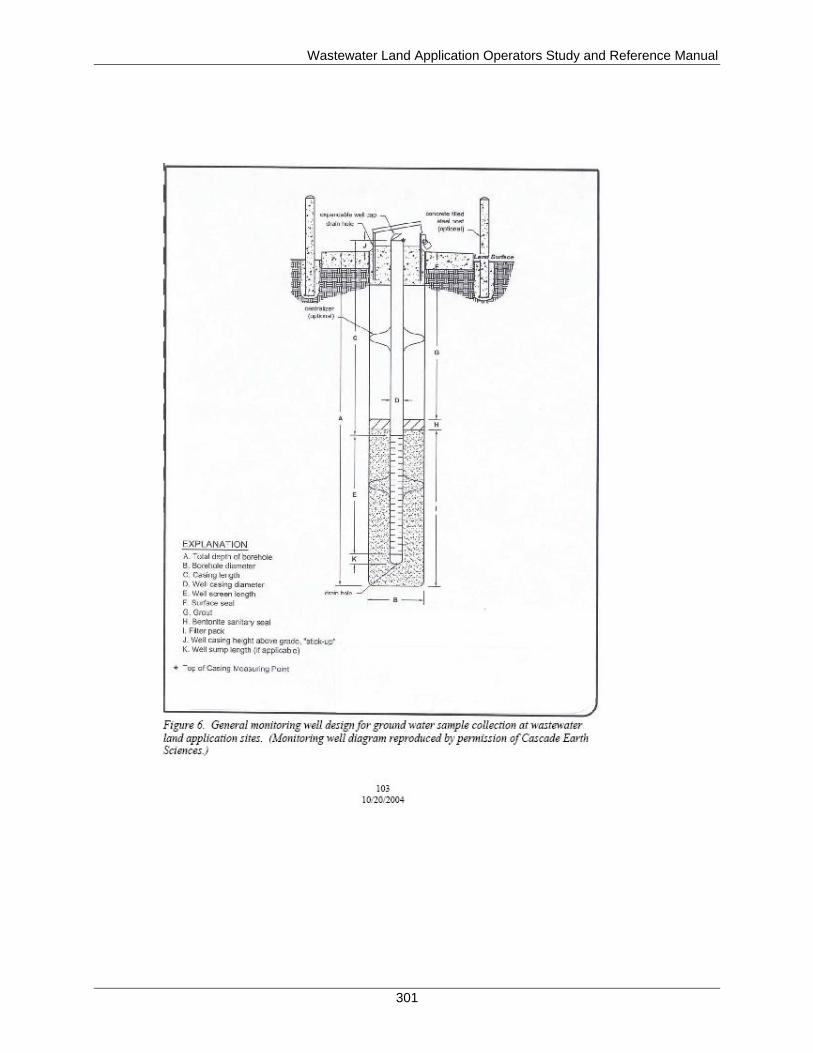
Wastewater Land Application Operators Study and Reference Manual
301
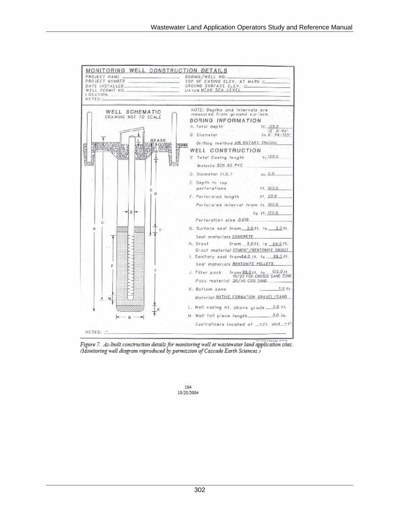
Wastewater Land Application Operators Study and Reference Manual
302
Wastewater Land Application Operators Study and Reference Manual
303
Appendix C. Reuse Permit: Annual Report Information Notes
The following details should be addressed in your annual report. For many of the questions,
provide a narrative explaining what the data indicate is happening at the site and why you
reached your conclusions.
1) Recycled Water/Irrigation Water Loading
a) Is recycled water land applied within limits of the permit?
b) Are recycled water loading calculations correct?
c) Are only permitted sites being used for reuse land application?
d) Is the growing season hydraulic loading (recycled water plus supplemental irrigation
water) substantially at the irrigation water requirement (IWR)?
e) Are nongrowing season recycled water loading rates within permitted limits?
2) Nutrient/Constituent Loading and Cropping
a) Which nutrients and/or constituents have loading limits in the permit?
b) Are nutrients/constituents land applied within limits of the permit?
c) Are nutrient/constituent loading calculations correct?
d) Are crops grown on reuse site with the recycled water land treatment acreage?
e) Are crop yields typical for the region?
f) Are crop uptake calculations done correctly?
3) Monitoring
a) Which media are required to be sampled in the permit during this reporting period?
(What are you monitoring?)
4) Ground Water Monitoring
a) Is the facility reporting monitoring data as required in the permit?
b) Are correct analytical procedures used?
c) Do monitoring data indicate compliance with permit limits (and “Ground Water Quality
Rule” [IDAPA 58.01.11] standards where applicable)?
d) Has analyses/interpretation of ground water data been done? If yes, describe.
5) Recycled Water/Irrigation Water
a) Is the facility reporting monitoring data as required in the permit?
b) Are correct analytical procedures used?
c) Are current water characteristics still as described in permit application materials?
d) Which water constituents have concentration limits in the permit?
e) Are constituent concentrations within limits of the permit?
f) Has analyses/interpretation of wastewater/recycled water/irrigation water data been done?
If yes, describe.
6) Soils
a) Is the facility reporting monitoring data as required in the permit?
Wastewater Land Application Operators Study and Reference Manual
304
b) Are correct analytical procedures used?
c) Has analyses/interpretation of soils data been done? If yes, describe.
7) Plant Tissue Monitoring
a) Is the facility reporting monitoring data as required in the permit?
b) Are correct analytical procedures used?
c) Has analyses/interpretation of plant tissue data been done? If yes, describe.
8) Other Monitoring
a) Describe the other monitoring required.
b) Is the facility reporting monitoring data as required in the permit?
c) Are correct analytical procedures used?
d) Has analyses/interpretation of other monitoring data been done? If yes, describe.
9) Other Permit Conditions, General Comments, and Recommendations
a) Were acts of noncompliance reported as required by the permit?
b) Was a compliance activity status update included in the annual report?
c) Are there follow-up items from a previous annual report review?
d) How were those follow-up items addressed?
Wastewater Land Application Operators Study and Reference Manual
305
Appendix D. Pumps and Motors
Before discussing specific types of pumps, it is important to understand the following general
concepts of pumps and controls:
Pump head
Horsepower
Pump capacity
Pump performance curves
Head
Pumps are designed to deliver liquid against a specific pressure. Water has a specific weight
(62.4 pounds per cubic foot or 8.34 pounds per gallon), and this weight resting on a surface
exerts a force on that surface. Force on a specific area is called pressure. Pressure is the total load
or force acting on a surface and is usually expressed in terms of pounds per square inch or
pounds per square foot. Pressure can also be expressed in terms of feet of water, for its origin is
the weight of a depth of water directly resting upon the area of measurement.
When pressure is measured in feet, it is called head. Pump head is defined as the resistance
against which a pump will operate. A water column 100 feet high will exert a pressure of
approximately 44 pounds per square inch. Conversely, 1 pound per square inch of pressure is
equivalent to 2.31 feet of head.
In most cases, pumps are installed to provide the pressure necessary to move water from one
location or elevation to another in a treatment system. Since the function of a pump is to add
pressure to the system, the pressure on the discharge side of the pump will always be higher than
the pressure on the suction side of the pump. In pump systems, measurements are taken from the
point of reference to the centerline of the pump. Pump heads include both static head (when the
pump is off) and dynamic heads (when the pump is on).
Horsepower
To purchase the appropriate pump for the job needed, it must be determined how much work the
pump will be required to do and the rate at which the work will be done:
Work is the operation of a force (pressure times area) over a specific distance, expressed
in units of foot-pounds. One foot-pound is the amount of work required to lift a one
pound object one foot off the ground.
Power is the rate at which work is being done, and it is expressed as foot-pounds per
second. Large units of power are called horsepower. One horsepower is 550 foot-pounds
per second.
Motor, brake, and water horsepower are terms used to indicate where the horsepower is
measured (Figure 1). Pumps are driven by motors, which are never 100% efficient; most motors
are usually 80% to 90% efficient. Motor horsepower (mhp) is the horsepower applied to the
motor in the form of electrical current. A portion of this horsepower is lost due to the conversion
of electrical energy to mechanical energy.
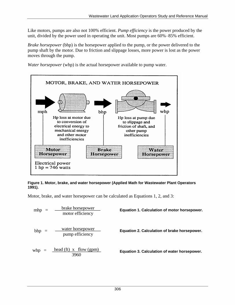
Wastewater Land Application Operators Study and Reference Manual
306
Like motors, pumps are also not 100% efficient. Pump efficiency is the power produced by the
unit, divided by the power used in operating the unit. Most pumps are 60%–85% efficient.
Brake horsepower (bhp) is the horsepower applied to the pump, or the power delivered to the
pump shaft by the motor. Due to friction and slippage losses, more power is lost as the power
moves through the pump.
Water horsepower (whp) is the actual horsepower available to pump water.
Figure 1. Motor, brake, and water horsepower (Applied Math for Wastewater Plant Operators 1991).
Motor, brake, and water horsepower can be calculated as Equations 1, 2, and 3:
Equation 1. Calculation of motor horsepower.
Equation 2. Calculation of brake horsepower.
Equation 3. Calculation of water horsepower.
brake horsepower
motor efficiency mhp =
water horsepower
pump efficiency bhp =
head (ft) x flow (gpm)
3960 whp =
Wastewater Land Application Operators Study and Reference Manual
307
Pump Capacity and Pump Delivery Rates
Each pump is designed to deliver a designated amount of flow against a specific head. This is the
design pump capacity or design pump delivery rate (gallons per minute). However, actual pump
capacity or delivery rates can vary, depending on the efficiency of a pump and the conditions
under which it is operated.
The pump capacity and quantity of flow, in turn, determine the time required for each pumping
or dosing cycle and the length of time between cycles. The amount of water pumped to a land
application field during a pump cycle is called the dosing volume (gallons). The pump delivery
rate is the amount of water pumped during a pump cycle divided by the pump run time
(minutes). The pump delivery rate efficiency is the measured pump delivery rate (gallons per
minute) divided by the design pump delivery rate times 100%.
Pump Performance
Pumps can deliver a wide range of flows, depending on design, speed, and total dynamic head.
The best source of information on a particular pump is the manufacturer’s pump performance
curve, which provides information on discharge (flow), power requirements, and head
characteristics.
Each pump is manufactured to operate most efficiently at a designated amount of head and flow.
Operating a pump as close to peak efficiency as possible allows it to operate with the least
amount of strain possible. Operating a pump well off peak efficiency can result in excessive
energy requirements and shortened pump life.
To better understand the performance and operating characteristics of pumps, wastewater land
application (WWLA) operators should become familiar with the pump curve that is supplied by
the manufacturer for each pump. A pump curve shows the relationships between pump head,
flow, efficiency, and horsepower. Pump curves can be used in case you need to modify your
operating conditions from the original irrigation design. This may be necessary, for example, if
you discover that the actual flow (discharge) exceeds the system design flow. A typical pump
curve is shown in Figure 2.
Pump curves usually show three curves on one sheet:
The head-capacity curve shows the discharge, in gallons per minute, the pump will
deliver against various heads when operated at the proper speed. This curve shows that as
the head increases, the discharge decreases, until there is no further discharge.
Conversely, as head decreases, flow increases.
The second curve, also plotted against flow, shows the efficiency at which the pump
operates at various points on the head capacity curve. This curve shows that no pump is
100% efficient, due to internal friction losses. The highest efficiency that can be hoped
for is around 85%. Efficiency can be expected to decrease with age and wear.
The third curve, the brake horsepower curve, shows power consumed plotted against
flow. If we know the total head at which the pump is operating, we can use the curve to
find the gallons pumped. The power required by the pump, as well as the pump
efficiency, can also be read from the curve for any set of conditions. This curve shows
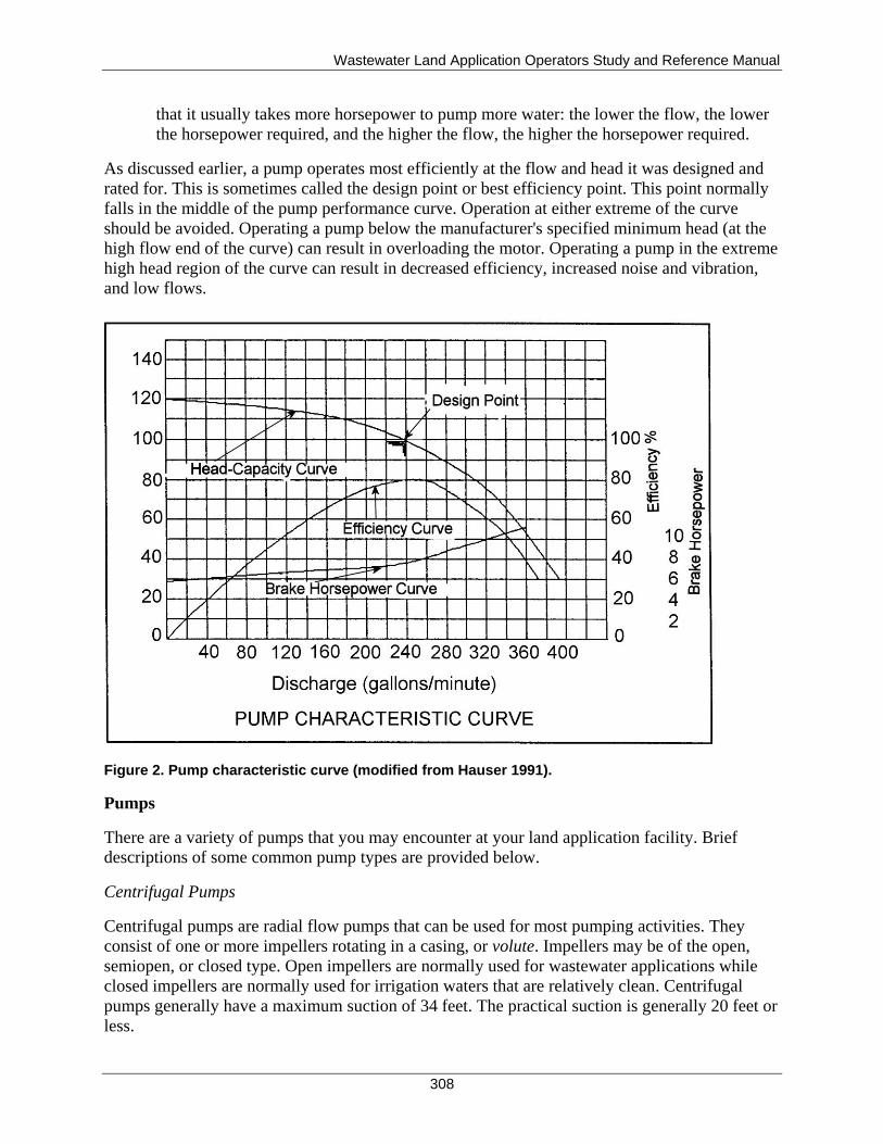
Wastewater Land Application Operators Study and Reference Manual
308
that it usually takes more horsepower to pump more water: the lower the flow, the lower
the horsepower required, and the higher the flow, the higher the horsepower required.
As discussed earlier, a pump operates most efficiently at the flow and head it was designed and
rated for. This is sometimes called the design point or best efficiency point. This point normally
falls in the middle of the pump performance curve. Operation at either extreme of the curve
should be avoided. Operating a pump below the manufacturer's specified minimum head (at the
high flow end of the curve) can result in overloading the motor. Operating a pump in the extreme
high head region of the curve can result in decreased efficiency, increased noise and vibration,
and low flows.
Figure 2. Pump characteristic curve (modified from Hauser 1991).
Pumps
There are a variety of pumps that you may encounter at your land application facility. Brief
descriptions of some common pump types are provided below.
Centrifugal Pumps
Centrifugal pumps are radial flow pumps that can be used for most pumping activities. They
consist of one or more impellers rotating in a casing, or volute. Impellers may be of the open,
semiopen, or closed type. Open impellers are normally used for wastewater applications while
closed impellers are normally used for irrigation waters that are relatively clean. Centrifugal
pumps generally have a maximum suction of 34 feet. The practical suction is generally 20 feet or
less.
Wastewater Land Application Operators Study and Reference Manual
309
Turbine Pumps
Turbine pumps are basically centrifugal pumps that are stacked on top of each other. Turbine
pumps may have up to 25 stages, depending on the type of impellers used. Each stage adds
pressure, not volume. These pumps are generally used for deep well irrigation systems or other
applications where the intake is below the liquid level and where high discharge pressures are
needed.
Submersible Pumps
Another type of centrifugal pump is the submersible pump. Submersible pumps are vertical,
heavy-duty centrifugal pumps designed to work while immersed in the water that they are
pumping. The watertight motor is also submerged. The surrounding water helps cool the pump
and motor, extending their life and efficiency.
Reciprocating, Piston, or Plunger Pumps
Positive displacement pumps are usually associated with water that contains high levels of solids,
and they must be operated with an open discharge valve. One such pump is the reciprocating
pump. A reciprocating pump (also called a piston or plunger pump) moves wastewater or sludge
by a piston or plunger that moves back and forth. This movement forces water from the suction
side to the discharge side of the pump.
Because the movement of the plunger or piston creates pressure inside the pump, this kind of
pump should never be operated against a closed discharge valve. To prevent a buildup of
pressure that could damage the pump or burst pipes, all discharge valves must be open before the
pump is started. Because force is exerted during the suction cycle, the suction valve should be
always left at least partly open.
Diaphragm Pumps
Another type of positive displacement pump is the diaphragm pump, often used for chemical
feed. Instead of using a piston or a plunger, a diaphragm (a flexible membrane) is used to force
water from the suction to the discharge side of the pump. In a diaphragm pump, water does not
come in contact with moving metal parts, an advantage over the reciprocating pump. This can be
important when pumping abrasive or corrosive liquids.
Peristaltic Pumps
Peristaltic pumps are used for water sampling or chemical feed. Peristaltic pumps, the oldest
pumps in existence, are another type of positive displacement pump. Water is moved through
flexible tubing by advancing rollers that squeeze the tubing. Nothing but the tube touches the
water, thus eliminating any risk of contamination. Pump design prevents backflow and siphoning
without valves.
Pumping System Components
Pumping system components include the pump itself, electrical connections to a motor, a shaft to
drive the pump, a seal between the water chamber and the motor, an impeller with inlet and
Wastewater Land Application Operators Study and Reference Manual
310
outlet ports, and a mounting stand. Rail systems are recommended when using large submersible
pumps to access pumps for repair or replacement.
Bearings
Several types of bearings are used in pumps, such as ball bearings, roller bearings, and thrust
bearings. Each bearing has a special purpose. The type of bearing used in each pump depends on
the manufacturer's design and application.
Bearings are machine parts designed to reduce friction between moving parts or to support
moving loads. There are two main kinds of bearings:
Antifriction type, such as the roller bearing and ball bearing, operate on the principle of
rolling friction.
Plain or sliding type, such as the thrust bearing, employ the principle of sliding friction;
thrust bearings are used to support the pump shaft.
Pump bearings should last for years if serviced properly and used in their proper application.
Whenever a bearing failure occurs, the bearing should be examined to determine the cause and,
if possible, eliminate the problem. Many bearings are ruined during installation or pump startup.
Packing
Pump packing reduces or eliminates internal liquid leakage within a pump. This is important
because the objective is to pump water, not air, and because air leakage can cause a pump to lose
suction. To keep air from being drawn into the pump, stuffing boxes are used. Each stuffing box
consists of casing, rings of packing, and a gland at the outside end. Each ring of packing should
be placed separately and seated firmly before adding the next. These rings are removable and
replaceable when wear enlarges the tiny gap between them and the impeller.
In addition to increasing the efficiency of the pump by reducing air leakage, pump packing can
prolong the life of the pump and shaft by reducing friction. The manufacturer's recommendations
should be followed in choosing a packing.
Mechanical Seals
Many pumps use mechanical seals in place of packing. Mechanical seals serve the same purpose
as packing: they prevent leakage between the pump casing and shaft. Like packing, they are
located in the stuffing box where the shaft goes through the volute; however, they should not
leak.
Mechanical seals have two faces that mate tightly and prevent water from passing through them.
One half of the seal is mounted in the pump or gland with an "O" ring or gasket, thus providing
sealing between the housing and seal face. This prevents water from going around the seal face
and housing. The other half of the mechanical seal is installed on the pump shaft. This part also
has an "O" ring or gasket between the shaft and seal to prevent water from leaking between the
seal part and shaft. There is a spring located behind one of the seal parts, which applies pressure
to hold the two faces of the seal together and keeps any water from leaking out. One half of the
seal is stationary, and the other half is revolving with the shaft.
Wastewater Land Application Operators Study and Reference Manual
311
Some of the advantages of mechanical seals are as follows:
They last from 3 to 4 years without maintenance, resulting in labor savings
Usually no damage results to the shaft sleeve when the seals are replaced
Continual adjusting, cleaning, or repacking is not required
Some of the limitations of mechanical seals include the following:
High initial cost
Competent mechanic required for installation
When they fail, pump must be shut down
Pump must be dismantled to repair
Lubrication
Pumps, motors, and drives should be oiled and greased in strict accordance with the
recommendations of the manufacturer. The best quality oils and grease obtainable should be
used. Overgreasing should be avoided, as too much grease will cause as much damage as lack of
lubrication. It is especially important not to overlubricate motor bearings as this can lead to
bearing seal failures. This has been the cause of an untold number of motor failures. The present
trend is toward the increased use of sealed bearings that require no additional grease for their
lifetime.
Priming a Pump
A pump will not operate unless it has been properly primed. A pump is considered primed when
the pump casing and suction piping are completely filled with liquid. A pump that has a positive
suction head will seldom lose its prime, whether the pump is on or off, and will likely only need
to be primed after it has been opened or replaced.
For pumps with a negative suction head (suction lift), the water tends to run back out of the
pump and down the suction line when the pump stops. If the casing is filled with air, the impeller
cannot create enough vacuum upon starting to draw water back into the unit, and the air will just
circulate around in the pump. In this situation, both the pump and motor will overheat in a short
time. If a positive suction head cannot be provided, the pump must be separately primed (filled
with water) each time it is started unless it is equipped with some type of self-priming device,
such as a foot valve, a vacuum pump or ejector, or a priming chamber.
Cavitation
Cavitation is the formation and collapse of a gas pocket or bubble on the blade of an impeller.
This condition results from unusually low pressures that can occur when pump inlet pressures
drop below the design inlet pressures or when the pump is operated at flow rates considerably
higher than design flows. Cavitation is accompanied by loud noises that sound like someone is
pounding on the impeller or valve with a hammer. Cavitation can also sound like rocks or gravel
passing through the pump or valve. Damage caused by cavitation can be severe, resulting in
replacement of the impeller or the impeller and volute.
Wastewater Land Application Operators Study and Reference Manual
312
Water Hammer
Also known as hydraulic shock, water hammer is an oscillation in pressure that results from a
too rapid acceleration or retardation of flow, such as when a valve is opened or closed very
rapidly. When a valve position is changed quickly, the water pressure in a pipe will increase and
decrease back and forth very quickly. This rise and fall in pressures can cause serious damage to
the system as well as producing a noise that sounds like someone hammering on a pipe.
Surge tanks installed in the areas where water hammer is a problem can absorb some of the
pressure.
Air release (sometimes called air relief) valves can also help minimize water hammer damage.
These devices allow the release of air in the distribution network while the system is
pressurizing. These valves are usually installed at high elevation points in a distribution network,
as well as at the end of laterals and trunk lines where air might be forced to a dead end.
Pump Controls
A variety of controls are used to operate pumping systems. These controls are used to activate
pumps, valves, water-level sensing devices, alarms, timers, counters, and meters. Controls are
contained in protected enclosures, called control panels. Control panels can be simplex (control
one pump), duplex (control two pumps), or multiplex (control more than two pumps). All control
panels should have a ground rod and a hand-off-automatic (HOA) switch that allows the WWLA
operator to override the control system and manually activate the pump. Panels should have
visual and audible alarms and an alarm silence switch.
Water-Level Sensing and Pump Control
Accurate sensing of high and low water levels is critical for proper timing of pump operation.
Control of pumping systems is achieved by an ON/OFF type of control, which starts and stops
pumps according to a level, pressure, or flow measurement.
Usually an ON/OFF pump control system responds to level changes in a tank of some type.
Water level can be sensed directly with a float or by a pressure change at the tank or pump site.
The pump is thus turned off or on as the tank level rises above or falls below the predetermined
level or pressure limits. These controls can either be single-point detection or continuous
detection.
Other possible pump controls include turning the pump OFF if there is a loss of the level signal
or low suction pressure.
Types of ON/OFF pump controls include the following:
Float switches
Pressure bulbs and diaphragm switches
Bubble tubes
Electrode switches
Ultrasonic sensors
Wastewater Land Application Operators Study and Reference Manual
313
Appendix E. Pipes, Connections, and Valves
Pipes
Before discussing specific types of pipes, the following definitions and abbreviations apply:
Outside diameter (OD).
Inside diameter (ID).
Iron pipe size (IPS). IPS is an old pipe size designation based on the inside diameter of
the pipe. IPS is still in use by some pipe manufacturers today.
Plastic irrigation pipe size (PIP). PIP pipe depending on the type of pipe (solvent weld,
belled end, or gasketed joint) have the same OD with varying IDs.
Class—Pipe's pressure rating (PR). PR is the standard pressure rating of the pipe.
Typically for steel pipe, it is the flange rating, and for PVC pipe, it is the long-term pipe
system rating (pipe and fittings).
Standard dimensional ratio (SDR) number; SDR is defined as the outside diameter
divided by the minimum wall thickness; the larger the SDR number, the thinner the pipe
wall thickness.
Nominal pipe thread (NPT). NPT is a standard for tapered pipe threads and is the
measure of the rate of pipe thread taper or change in pipe thread diameter over a distance.
The taper rate for all NPT threads is 1/16.
Piping used in land application systems can either be made of concrete, metal (iron, stainless
steel, copper, aluminum) or plastic (polyvinyl chloride [PVC] or polyethylene). Several of these
are discussed below:
Concrete—Concrete pipe is primarily used for large diameter lines. The most common type of
concrete pipe is manufactured by wrapping a wire around a steel cylinder and using a cement
coating to cover the steel cylinder both internally and externally. This pipe is made to withstand
internal pressures up to 300 pounds per square inch (psi) and can be placed in trenches up to 70
feet deep. Concrete pipe is very resistant to corrosion except in very low pH waters. The cement
mortar is the protective agent for the steel cylinder; therefore, the pipe must be handled with
care. Damage to the cement mortar either internally or externally will subject the pipe to
corrosion. Advantages of this material are its ability to withstand high external loads and
corrosion. Major disadvantages are its weight and the care with which it must be installed.
Cast Iron—Cast iron pipe is some of the oldest piping material in use today. It is now
manufactured by a process called spin casting, during which molten iron is injected into a
spinning mold. The result is a pipe of consistent diameter and wall thickness. Cast iron pipe can
withstand high working pressures. Pressure ratings of 350 psi are common. However, the
material cannot withstand sharp shock loads either internally or externally.
Steel—Steel pipe is made by extruding or welding sections of steel to form a pipe. This pipe falls
into two categories: mill pipe and fabricated pipe. Steel pipe is classed as a flexible conduit,
meaning that it has the ability to withstand a 3% deflection of the diameter without damage to
the pipe. Steel pipe is commonly manufactured to meet very high pressures (up to 700 psi is not
uncommon). However, under a vacuum it will collapse. Because steel pipe is a flexible conduit,
Wastewater Land Application Operators Study and Reference Manual
314
it requires a selection of wall thickness suitable to withstand external loads as well as internal
loads. Steel can easily be shaped into various sizes and shapes, which is one of its major
advantages. It also has a high tensile strength and high ductility. These characteristics give it the
ability to withstand high internal and external loads. The main disadvantage of steel pipe is that it
is easily attacked by corrosive elements, which results in high maintenance costs. An additional
disadvantage is that it will collapse under a vacuum. Epoxy coated steel is more resistant to
corrosion and offers longer life spans.
Cement asbestos—Cement asbestos (or AC pipe) is made from Portland cement, long fiber
asbestos, and silica sand. The pipe is formed on a spinning anvil and cured in an autoclave. Three
common classes of pipe are made: Class 100, 150, and 200. These classes refer to the working
pressure rating of the pipe. AC pipe is easily corroded and has high hydraulic capabilities and a
low shear strength. It is easily damaged by shock loads, either internally or externally.
Aluminum—Aluminum pipe is used in aboveground situations as portable pipe. It is often used
to pipe water to a traveling irrigation device, such as a center pivot tower or traveling gun hose-
reel. Aluminum pipe is sometimes used in solid set systems as well. It is lightweight, very
portable, and easily connected. Aluminum pipe does not offer good strength and is easily
damaged by machinery or fallen trees. Often, leaks can occur until the distribution system is
fully pressurized. Aboveground aluminum pipe is not suitable where winter operation is
necessary, as freezing causes pipe damage as well as poor function of the sprinkler heads
attached to the pipe due to ice clogging.
Ductile Cast Iron Pipe (DIP)—Ductile cast iron pipe is made by injecting magnesium into the
cast iron during the molding process. The magnesium alters the shape of the carbon structure of
the cast iron, giving the pipe superior beam strength. It will resist high impacts and is more
corrosion resistant than gray cast iron. Ductile iron pipe is classed by wall thickness. The
common thickness class ranges from 50 through 56; the higher the number, the thicker the wall.
However, wall thickness also varies with the size of the pipe. The thickness class needed for a
particular condition is based on the internal working pressure, depth of the cover, pipe size, and
type of bedding condition to be used. Because of its ability to withstand high stress, extreme
beam and crush loads, unusual shock, unstable bedding and deep fills, ductile cast iron pipe is
one of the few materials that can be used in extreme conditions. Its disadvantages are its weight
and its susceptibility of corrosion.
PVC—PVC pipe is made from unplasticized polyvinyl chloride. This material only gained wide
acceptance in the water industry when a thicker walled material was developed and an acceptable
standard was adopted. The standard that governs most of this thick-walled PVC pipe is called C-
900. This distinguishes it from other PVC pipe that has a thinner wall. PVC is manufactured in
various sizes and wall thicknesses.
Three groupings of pipe material are commonly used in the water industry.
Scheduled Pipe—First there is the scheduled pipe. Schedule refers to the thickness of the pipe; a
higher number denotes a thicker pipe. The two common schedules are schedule 40 and schedule
80. This material is not normally placed in a trench but is used as piping in small pump stations
and in chlorine stations. The wall thickness, ID, and OD of scheduled pipe are based on steel
Wastewater Land Application Operators Study and Reference Manual
315
pipe dimensions. The working pressure will vary from 600 psi for 1/2-inch schedule 40 to 160 psi
for 8-inch schedule 40.
Pressure Pipe—Second there is what is called pressure pipe. This material is manufactured in
iron pipe OD sizes (IPS). The common classifications of this pipe are 160 psi, 200 psi, and 315
psi. This material can be joined by either push-on gasket fittings or solvent welds.
Class Pipe—Third, there is class pipe, which is manufactured in both iron pipe OD sizes and
cast iron OD sizes. The three classes of this material are based on a standard working pressure.
The classes are 100, 150, and 200. The wall thickness of the pipe increases as the pipe diameter
increases. Class 200 PVC pipe with cast iron pipe outside dimensions is the most common class
pipe used in the wastewater industry.
The primary advantages of PVC pipe are its light weight, the ease with which it can be cut, and
its ability to resist corrosion. One of its disadvantages is its inability to withstand high impact
and shocks. It is also sensitive to sunlight if stored outside too long and will elongate in high
ambient temperatures, making installation difficult. Plastic pipe should not be used in areas
where petroleum products may be present. Finally, in cold weather it becomes brittle, requiring
special handling.
Connections
A connection is a collar or coupling that fits over adjacent ends of pipe to be joined, and which,
when drawn tight, holds the pipe together either by friction or by mechanical bond. Connections
include the following:
Flange—A connection made by flanges bolted together; the joint is made water-tight by a
gasket placed between the two flanges.
Mechanical joint—Any form of flexible joint involving lugs and bolts; uses a bell and
spigot arrangement. A rubber gasket is placed around the spigot. The gasket is forced into
the bell by a metal ring (called a follower ring) that is held to the bell by a series of bolts.
Bell and spigot—A form of joint used on pipes with an enlarged diameter or bell at one
end and a spigot at the other, which fits into and is laid in the bell. The joint is then made
tight by lead, cement, rubber O-ring, or other jointing compounds or materials.
Threaded—A connection made by threading a male end section of pipe or fitting into a
female fitting or adapter. With metal threads, pipe compound is typically required for a
waterproof seal. Teflon thread tape may be used on metal or PVC pipe threads.
PVC cement—Also called "solvent weld"; uses a special primer and glue to physically
mate (connect) pipe and fittings. The glue causes the PVC to bond by a chemical reaction
that melts the two pipes, allows them to combine, then cools and solidifies into the
banded pipe.
Valves
A valve is a device installed in a pipeline to control the magnitude and direction of the flow. It
consists essentially of a shell and a disk or plug fitted to the shell. Valves vary in construction
and size, depending upon their function. Some are classified according to their method of
operation or design and some are named for the functions they perform. Valves can be operated
Wastewater Land Application Operators Study and Reference Manual
316
automatically or manually. Types of valves encountered in a land application system include the
following:
Gate valve—Typically used as a shut-off valve. A disc in the valve is raised and lowered
by a threaded stem or sliding stem to open and close the valve. Gate valves are used in
pressure distribution systems to regulate the rate of water flow. Gate valves are designed
to operate fully open or fully closed.
Plug valve—Often used in multiple outlet valves, such as diversion valves. Like a gate
valve, a plug valve has an unobstructed flow, yet requires only a 90o turn to open it. The
movable control element is a cylindrical or conical plug, in contrast to a flat disk. The
valve is turned directly with a key to change the less-than-fully open port.
Butterfly valve—Has a disc that turns sideways to open the valve. It is a one-quarter turn
valve and can be used for throttling relatively clean water. The disk, as it opens or closes,
rotates about a spindle supported by the frame of the valve. The valve is opened at a
stem. At full opening, the disk is in a position parallel to the axis of the conduit.
Check valve—Allows water to flow in only one direction. Check valves either have ball
or flapper mechanisms that prevent backflow. Check valves consist of a valve provided
with a disk hinged on one edge so that it opens in the direction of normal flow and closes
with reversal of flow.
Solenoid valve—Uses a solenoid (an electric coil) to open and close small openings to
divert fluid from one side of a diaphragm to the other. When the pressure on top of the
diaphragm is equal to the inlet pressure, the valve will remain closed. When pressure is
released from on top of the diaphragm, a pump can then open the device. Solenoids can
operate small valves or other electrical switches.
Pressure relief valve—Valve that, when actuated by static pressure above a
predetermined level, opens in proportion to the excess above this level and reduces the
pressure.
Air relief valve—Designed to allow the release of air pressure in an irrigation system. Air
relief valves are typically installed at the distal ends of long runs of piping, at high
elevation points in fields, and at other places where air may be trapped, such as at a field
valve or sharp turn in the piping. These valves have a ball or some mechanism that allows
air to escape but shuts tightly when water pressure enters them. Their purpose is to allow
air that is in the piping system to escape when water is being pumped into the system and
to help eliminate damage to pipes and sprinklers from excessive air pressure.
Globe valve—Is directed through the valve in a specific direction, then is forced to
change direction and go through a large orifice, hit a disk and again change direction to
exit the valve. This induces head loss and makes it a good throttling device. It has a
round, ball-like shell and horizontal disk.
Bleeder valve—Used for draining a tank, tube, etc.
Wastewater Land Application Operators Study and Reference Manual
317
Appendix F. Soil Sampling
The following document on soil sampling can also be found at
http://www.cals.uidaho.edu/edComm/pdf/EXT/EXT0704.pdf.
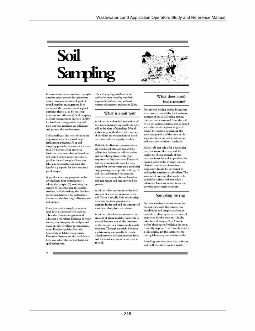
Wastewater Land Application Operators Study and Reference Manual
318
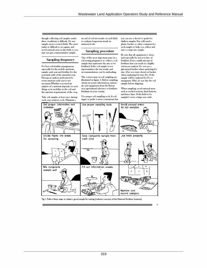
Wastewater Land Application Operators Study and Reference Manual
319
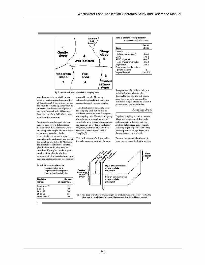
Wastewater Land Application Operators Study and Reference Manual
320

Wastewater Land Application Operators Study and Reference Manual
321
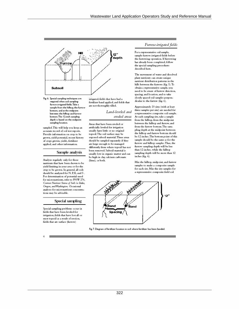
Wastewater Land Application Operators Study and Reference Manual
322
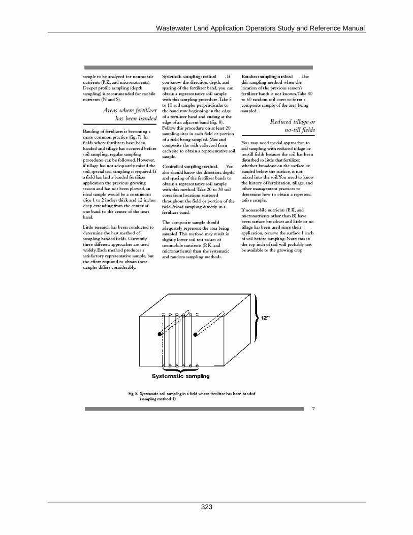
Wastewater Land Application Operators Study and Reference Manual
323
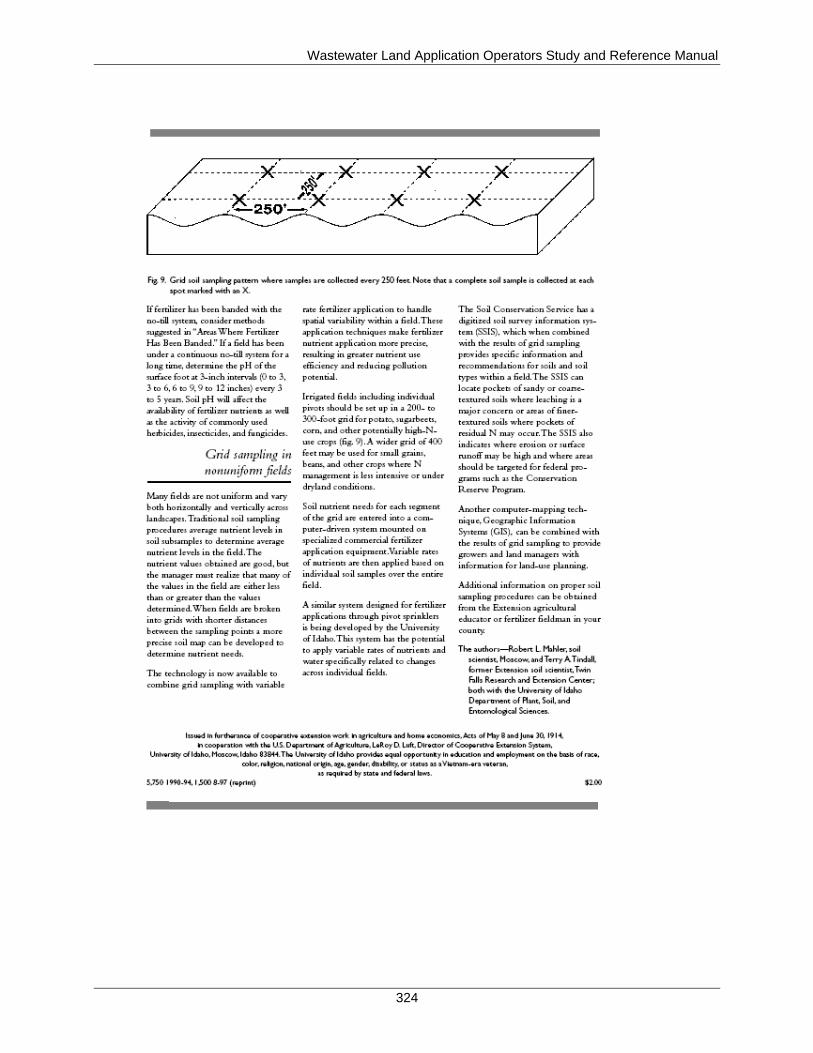
Wastewater Land Application Operators Study and Reference Manual
324
Wastewater Land Application Operators Study and Reference Manual
325
Appendix G. Plant Tissue Sampling
The following is an excerpt from the Guidance for Land Application of Municipal and Industrial
Wastewater, which can be accessed in its entirety at http://www.deq.idaho.gov/media/516329-
guidance_reuse_0907.pdf.
7.6.5.1 Sampling
Only the plant parts that are removed from the site need be sampled. In the case of a hay crop,
the entire plant top is cut and removed, so the entire plant should be sampled. In the case of small
grains, if the grain and stover (above-ground plant parts excluding the seed) are both harvested
and removed, both should be sampled. If the stover is left on site, then only the grain should be
sampled.
CES (1997) outlines plant tissue sampling methods, which are summarized here. Plant tissue
samples of green, growing crops such as forages should be taken immediately prior to harvest.
Sampling forage crops immediately prior to harvest can result in 10 to 20 percent higher nitrogen
levels because of plant tissue degradation following harvest. Samples should be collected to be
representative of the crop at the time of harvest or just prior to harvest. Sampling of small areas
of the field where plants are under severe moisture or temperature stress is not recommended.
Plants that are dust covered, mechanically injured, diseased, or dead should not be sampled
(Walsh and Beaton, 1973). The exception to this is when mechanical injury, disease or crop
death is representative of the material being harvested. Crop tissue should be tested in these
cases.
Samples should be collected at random locations in the hydraulic management unit. Specific crop
types require particular sampling methods. For harvested grain, bean, silage or green chop, one
grab sample from each day of harvest should be collected. They should be placed in paper bag
and refrigerate, then mixed and a composite sample (1 liter wet or ½ liter dry) sent to the
laboratory. For bailed hay, collect three composite samples from each harvest from each field.
Each hay sample should be composited from at least ten cores from the ends of randomly
selected bales. Then mix and send to the laboratory.
Potatoes require special sampling methods due to their size and the presence of two harvested
plant parts, namely the potato and the vines. Collect on grab sample per day during harvest
consisting of at least five potatoes. Quarter each potato and discard three of the quarters. Retain
one quarter from each potato for a daily grab sample. Keep subsamples refrigerated and send all
quarters to the laboratory for analysis. If the potato vines are to be burned, vine yield and nutrient
(nitrogen only) uptake by the vines should be measured. Collect the vines from three four-foot
sections of row in four locations in each hydraulic management unit (CES, 1997). Then reduce
the sample size by splitting the pile of collected vines prior to shipping to the laboratory.
Refrigerate after sampling and send at least 1 liter, but preferably one gallon, of volume of
sample to the laboratory.
For forage crops, each sample should consist of the clippings from a minimum ten square feet of
area. A square wooden frame or a wire whoop placed on the forage is effective to delineate the
area to be sampled. The frame should be randomly dropped along a transect or grid pattern. The
Wastewater Land Application Operators Study and Reference Manual
326
plants should be clipped within the frame at the same level that would result from the mechanical
harvesting equipment. Hand operated or other clippers may be used.
Place each composite sample in a large paper bag so the sample can ‘breath’ (some sources
recommend a perforated plastic bag). Put the sample in a cool place and deliver to the laboratory
within two hours (CES, 1997). Ship or store samples in a chilled cooler if delivery in two hours
cannot be accomplished. Delivery within 24 to 48 hours is acceptable if samples are kept dry and
chilled in ‘breathable bags. Illinois (No Date) recommends a quick washing of plant tissue in a
0.1 – 0.3 percent non-phosphate containing detergent accompanied by three rinses in de-ionized
water, in order to remove any dust, fertilizer, pesticide or other residues from the leaf surfaces.
As an alternative to collecting and transporting fresh plant tissue samples to the laboratory within
short time-frames, samples may be dried in a clean muslin bag or tray inside a forced draft oven
at 65 C for 48 hours. Tissue samples may then be ground after drying and placed in a bottle and
allowed to dry for an additional 24 hours at 65 C. After this, samples are ready for analyses
(Illinois, No Date). Walsh and Beaton (1973) may be consulted for further information regarding
plant tissue sampling and analyses.
Wastewater Land Application Operators Study and Reference Manual
327
Appendix H. Ground Water
Equipment and Supplies for Sampling Ground Water
Prior planning and careful preparation of field equipment before sampling will ensure good
results from the laboratory. The following is a list of supplies and equipment to be used when
sampling ground water:
Disposable gloves
Documentation (forms, log books, and operations and maintenance [O&M] manual)
Indelible ink pen
Well lock keys
Tape measure
Water level monitoring device and supplies (batteries, chalk, and paste as needed)
Field parameter meters with calibration standards
Decontaminated sampling pump with proper tubing and power supply
Bailers with line
Sample bottles
Sample labels
Packing tape
Stop watch
Graduated cylinder
Filtration equipment
Cooler with cold packs or ice
Cleaning buckets and containers
Plastic garbage bags
Small sealable plastic bags or containers
Plastic sheeting
Paper towels and hand soap
Cleaning brushes
Phosphate-free laboratory soap
Deionized organic-free water and hand sprayers
High purity laboratory grade hexane, acetone, or isopropanol (all available from
laboratory supply companies)
Customized kits for sample collection may be supplied by the laboratory. These kits include all
the items needed for collection and shipment of samples. Follow laboratory instructions and read
container labels. Be careful not to discard preservatives that may have already been added to
some containers.
If not using a kit, use only new containers or sanitized reusable containers, supplied by a lab, of
the appropriate types for the required parameters. Select and prepare them according to the
laboratory’s instructions. Label sample containers before sample collection and record the type
and amount of preservative required on each sample label. Ensure that all sampling equipment,
such as bailers, containers, and tubing has been selected and thoroughly cleaned based on the
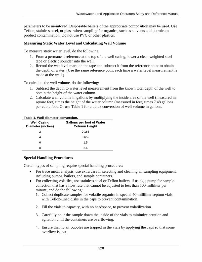
Wastewater Land Application Operators Study and Reference Manual
328
parameters to be monitored. Disposable bailers of the appropriate composition may be used. Use
Teflon, stainless steel, or glass when sampling for organics, such as solvents and petroleum
product contamination. Do not use PVC or other plastics.
Measuring Static Water Level and Calculating Well Volume
To measure static water level, do the following:
1. From a permanent reference at the top of the well casing, lower a clean weighted steel
tape or electric sounder into the well.
2. Record the wet level mark on the tape and subtract it from the reference point to obtain
the depth of water. (Use the same reference point each time a water level measurement is
made at the well.)
To calculate the well volume, do the following:
1. Subtract the depth to water level measurement from the known total depth of the well to
obtain the height of the water column.
2. Calculate well volume in gallons by multiplying the inside area of the well (measured in
square feet) times the height of the water column (measured in feet) times 7.48 gallons
per cubic foot. Or use Table 1 for a quick conversion of well volume in gallons.
Table 1. Well diameter conversion.
Well Casing Diameter (inches)
Gallons per foot of Water Column Height
2 0.163
4 0.652
6 1.5
8 2.6
Special Handling Procedures
Certain types of sampling require special handling procedures:
For trace metal analysis, use extra care in selecting and cleaning all sampling equipment,
including pumps, bailers, and sample containers.
For collecting volatiles, use stainless steel or Teflon bailers, if using a pump for sample
collection that has a flow rate that cannot be adjusted to less than 100 milliliter per
minute, and do the following:
1. Collect duplicate samples for volatile organics in special 40-milliliter septum vials,
with Teflon-lined disks in the caps to prevent contamination.
2. Fill the vials to capacity, with no headspace, to prevent volatilization.
3. Carefully pour the sample down the inside of the vials to minimize aeration and
agitation until the containers are overflowing.
4. Ensure that no air bubbles are trapped in the vials by applying the caps so that some
overflow is lost.
Wastewater Land Application Operators Study and Reference Manual
329
5. If bubbles are noted when the vials are inverted and tapped, set those aside to be
discarded.
6. Repeat the collection procedure using new vials. Include a trip blank of organics-free
water, which must be obtained from the laboratory with each cooler containing
samples collected for volatile organics.
For coliform samples, collect directly into sterilized glass or sterilized plastic bottles that
have been kept closed until ready to be filled. The sterilized containers often contain a
preservative. Do not rinse prior to filling. Hold the bottles near the base until filled.
Recap the bottles immediately, using care not to contaminate the bottles or lids. Store as
required.
Filtering Samples
Adhere to the following requirements when filtering samples:
Do not filter samples for coliforms.
If there is a special request for the collection of a filtered sample for any analysis, use the
appropriate type of filtering apparatus and filters.
In low yielding wells and those containing high levels of suspended solids, lowering a
bailer to below the static water level and allowing the well to recover into the bailer
should produce a cleaner sample.
Use purging and sampling techniques previously described to minimize agitation of
sediment in affected wells and reduce the need for filtering. A pump used for purging and
sampling will produce better samples from such wells.

Wastewater Land Application Operators Study and Reference Manual
330
This page intentionally left blank for correct double-sided printing.
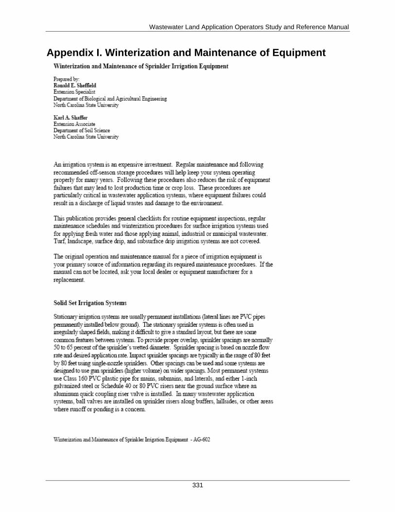
Wastewater Land Application Operators Study and Reference Manual
331
Appendix I. Winterization and Maintenance of Equipment
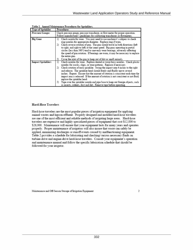
Wastewater Land Application Operators Study and Reference Manual
332
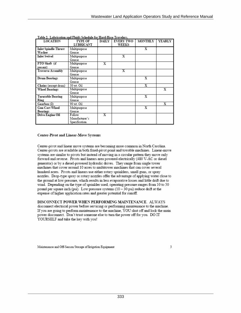
Wastewater Land Application Operators Study and Reference Manual
333
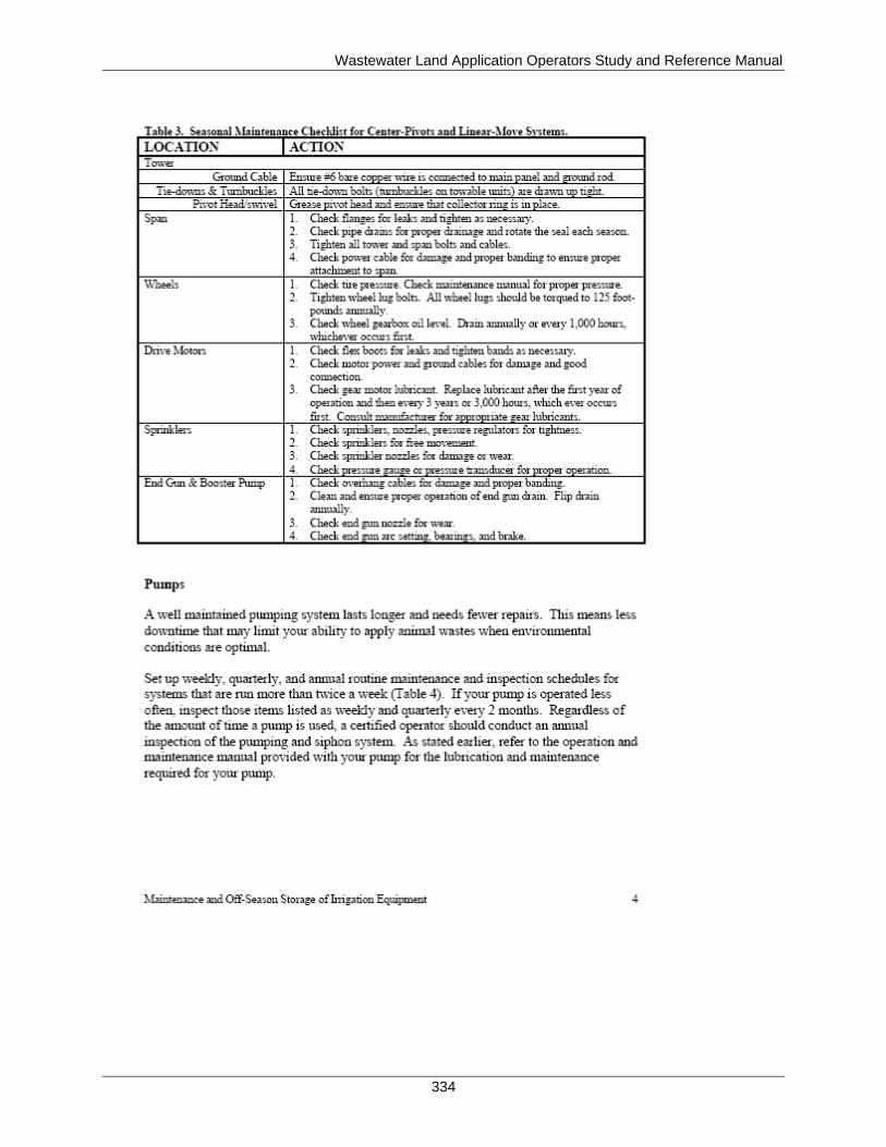
Wastewater Land Application Operators Study and Reference Manual
334
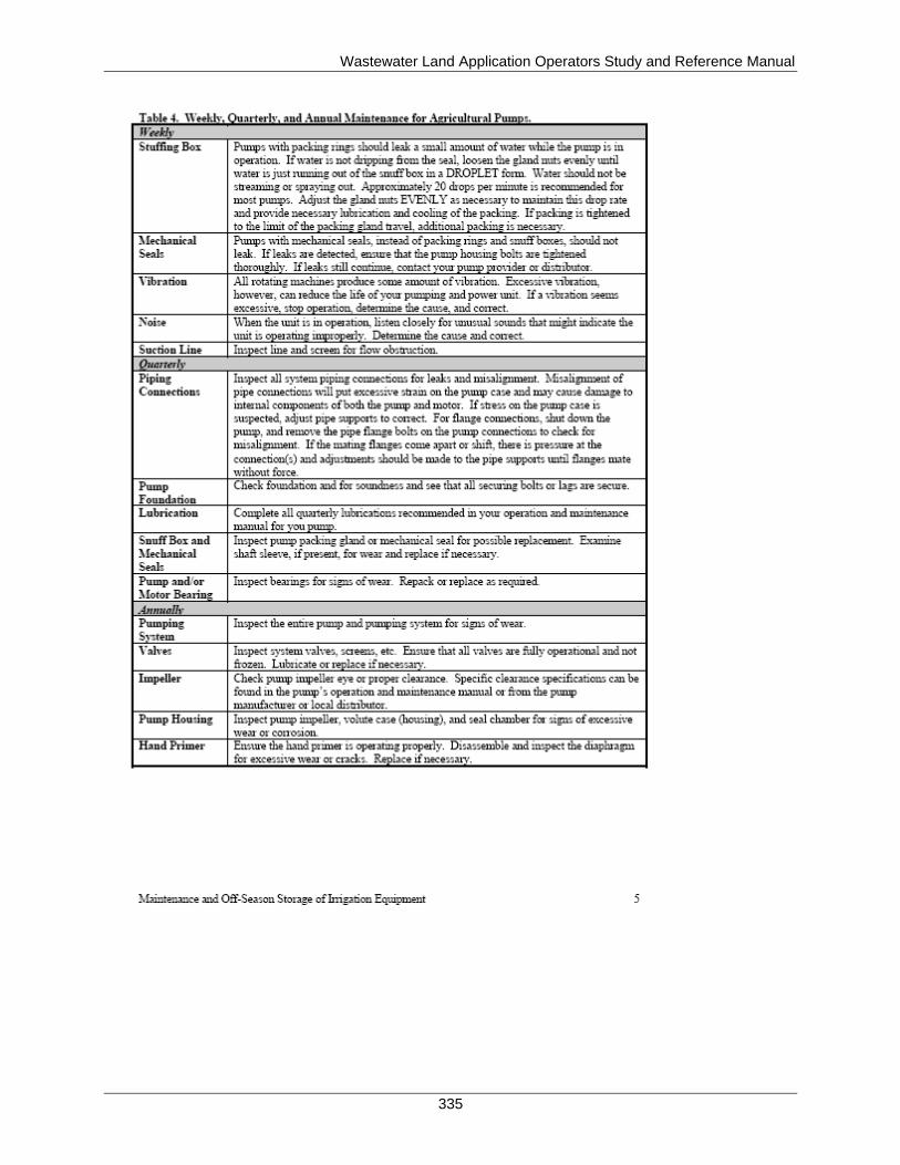
Wastewater Land Application Operators Study and Reference Manual
335
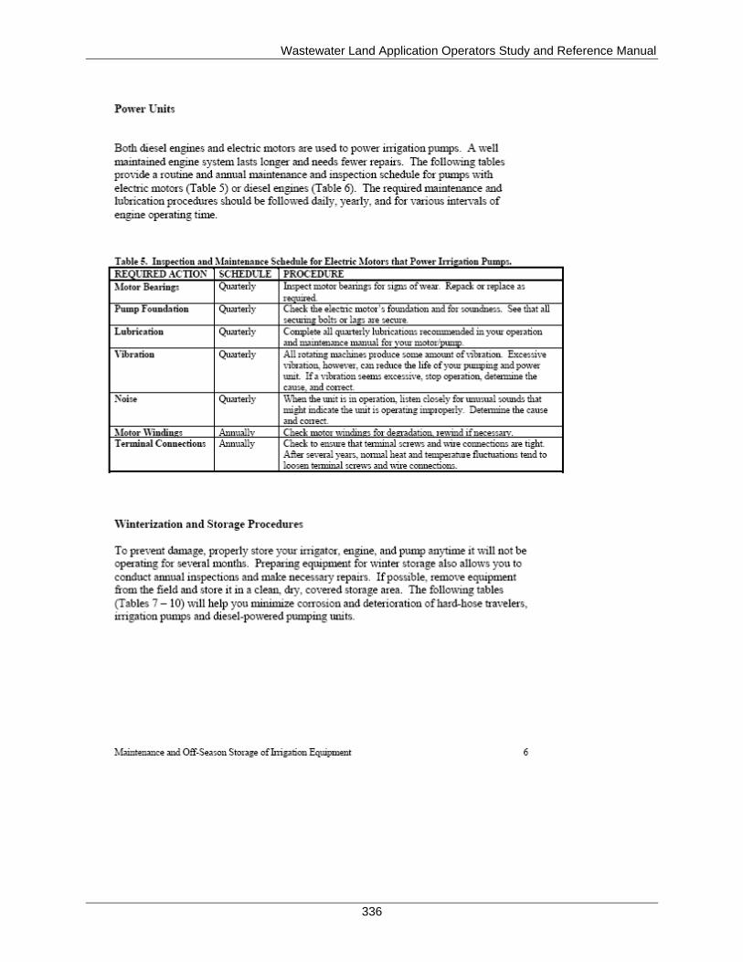
Wastewater Land Application Operators Study and Reference Manual
336

Wastewater Land Application Operators Study and Reference Manual
337
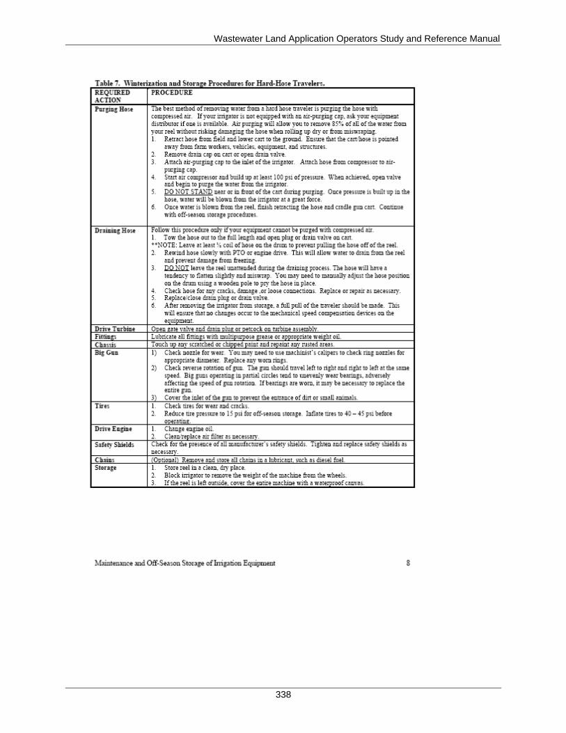
Wastewater Land Application Operators Study and Reference Manual
338
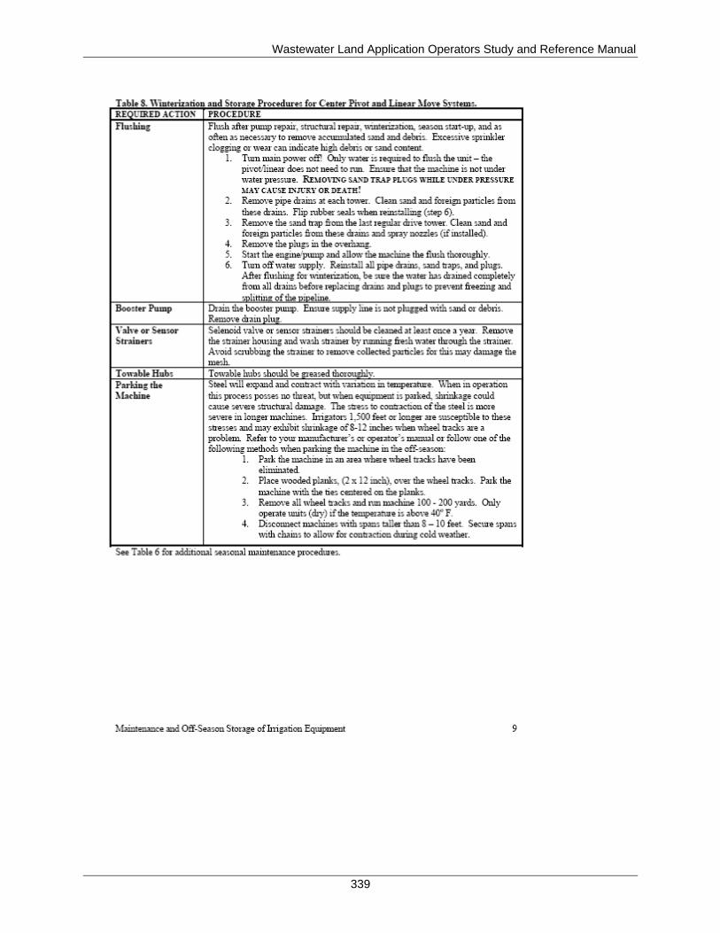
Wastewater Land Application Operators Study and Reference Manual
339
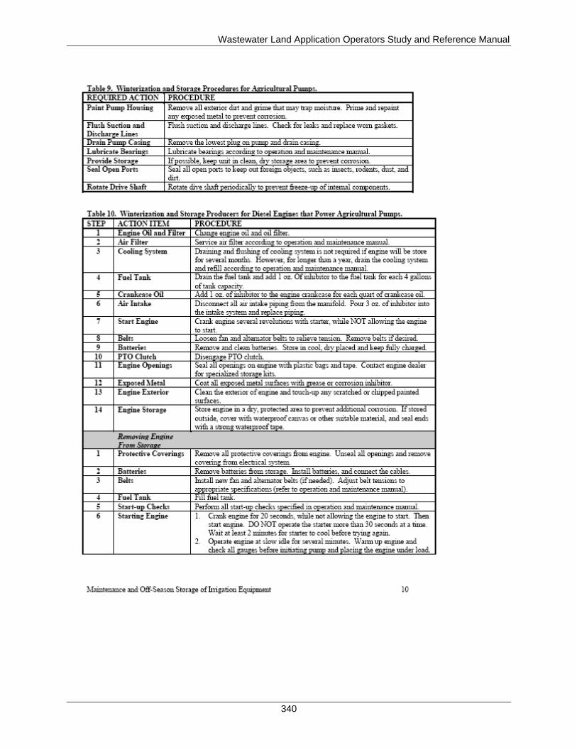
Wastewater Land Application Operators Study and Reference Manual
340