WASTE TREATMENT AND IMMOBILIZATION PLANT CHAPTER 4A ...
40
WA7890008967 Hanford Facility RCRA Permit Dangerous Waste Portion Change Control Log Waste Treatment and Immobilization Plant WASTE TREATMENT AND IMMOBILIZATION PLANT CHAPTER 4A FIGURES AND DRAWINGS CHANGE CONTROL LOG Change Control Logs ensure that changes to this unit are performed in a methodical, controlled, coordinated, and transparent manner. Each unit addendum will have its own change control log with a modification history table. The “Modification Number” represents Ecology’s method for tracking the different versions of the permit. This log will serve as an up to date record of modifications and version history of the unit. Modification History Table Modification Date Modification Number 09/05/2017 8C.2017.6F 08/2012
Transcript of WASTE TREATMENT AND IMMOBILIZATION PLANT CHAPTER 4A ...

WA7890008967 Hanford Facility RCRA Permit Dangerous Waste Portion
Change Control Log Waste Treatment and Immobilization Plant
WASTE TREATMENT AND IMMOBILIZATION PLANT
CHAPTER 4A FIGURES AND DRAWINGS CHANGE CONTROL LOG
Change Control Logs ensure that changes to this unit are performed in a methodical, controlled, coordinated, and transparent manner. Each unit addendum will have its own change control log with a modification history table. The “Modification Number” represents Ecology’s method for tracking the different versions of the permit. This log will serve as an up to date record of modifications and version history of the unit.
Modification History Table
Modification Date Modification Number 09/05/2017 8C.2017.6F
08/2012

WA7890008967 Hanford Facility RCRA Permit Dangerous Waste Portion
Change Control Log Waste Treatment and Immobilization Plant
This page intentionally left blank.

WA7890008967 Waste Treatment and Immobilization Plant
Chapter 4A.1
1
CHAPTER 4A 2 FIGURES AND DRAWINGS 3
4

WA7890008967 Waste Treatment and Immobilization Plant
Chapter 4A.2
1 2
3 This page intentionally left blank. 4
5

WA7890008967 Waste Treatment and Immobilization Plant
Chapter 4A.3
1 CHAPTER 4A 2
ENGINEERING FIGURES 3
4 The figures listed below are included in this chapter, and are to be used in conjunction with the text in the 5 Dangerous Waste Permit (DWP) Chapter 4. 6
7 Figure 4A-1 WTP Simplified Flow Diagram ................................................................................... 5 8
Figure 4A-2 Primary Pretreatment Process Systems ........................................................................ 6 9
Figure 4A-2A Primary Pretreatment Process Systems (Continued) .................................................... 7 10
Figure 4A-3 Primary LAW Vitrification Systems ............................................................................ 8 11
Figure 4A-4 Primary HLW Vitrification Systems ............................................................................ 9 12
Figure 4A-11 Cesium Resin Addition Process System (CRP) ......................................................... 10 13
Figure 4A-21 LAW Melter Process System (LMP) ......................................................................... 11 14
Figure 4A-24 LAW Container Finishing Handling System (LFH) .................................................. 12 15
Figure 4A-27 HLW Melter Process System (HMP) ......................................................................... 13 16
Figure 4A-38 Typical Tank System – Cesium Ion Exchange Column ............................................. 15 17
Figure 4A-48 Typical System - LAW Melter Process System (LMP) ............................................. 17 18
Figure 4A-53 Typical Tank System – HLW Melter Feed Process System (HFP) ........................... 18 19
Figure 4A-59 Typical System - Containment Building (Sheet 1) ..................................................... 19 20
Figure 4A-59 Typical System - Containment Building Typical Design Features Crosswalk 21 (Sheet 2) ..................................................................................................................... 21 22
Figure 4A-65 Simplified General Arrangement Pretreatment - Plan at El. 98 ................................. 25 23
Figure 4A-118 Schematic of an Example IHLW Container and Label .............................................. 26 24
Figure 4A-119 Schematic of an Example ILAW Container and Label .............................................. 27 25
Figure 4A-120 Typical Arrangement of a Reverse Flow Diverter ..................................................... 29 26
Figure 4A-121 Basic Reverse Flow Diverter Design ......................................................................... 31 27
Figure 4A-122 Typical Arrangement of a Steam Ejector System ...................................................... 33 28
Figure 4A-123 Typical Seal Pot Arrangement ................................................................................... 34 29
Figure 4A-124 Typical Breakpot Arrangement .................................................................................. 35 30
Figure 4A-127 Typical Bulge Configuration ...................................................................................... 36 31
Figure 4A-128 Typical Primary Containment Sump Conceptual Design........................................... 37 32 33

WA7890008967 Waste Treatment and Immobilization Plant
Chapter 4A.4
1 2 3
This page intentionally left blank. 4 5

WA7890008967 Waste Treatment and Immobilization Plant
Chapter 4A.5
1
Figure 4A-1 WTP Simplified Flow Diagram 2 3
.... .. ............... . .... .. '.' ' ''''' ' .. .. ... . ........................... .. ... ·. · ............... . ....... ..... '''' ' . ' . ' . ' . .. .... .. .. :
Pretreatment Pia nt
Condensale 1--------c<,,oet...::<----r---~ to U:RFIETF
LAWFeed1-....,.==-~ Cewm
Concentrnles
HLW Blending Vessel
I.letter Feed Preparation
PT
S™*
HLW Vitrification Plant
.__""_:._·_i:-_"_'PI_• __ ? •• .------••
S1-S3:,q>ltPON 1 S?- SitrO)f Port2 AgM · $8.li'i l.~ r; r,e ET1" •E.'11.itntTfUnltrlflCCJ rif)/.E" -~~C'/ J.'S: Dnl"IIXlf M!PA -1gl~C, Pt10..tl2Nl .-4tr ,._w - ~41!vth ,u~ I.AW · L0'#-3d~WU~ LE!v . uc,g,c, e:::,,IOlC'9CIOll foctlJ
HlWSuck
PJl.4 •AIM Jt1 llt:tt Plfl) • !\NtM fO'# Oliffltf ses -Sit.wn~cetoScr.botr SCft - St~e QU;tJO:ReOJctb'I TCO - 1brn111 c.aa-,,oeoxa¥.10n Wf.Sf> • Wftf~tiCPtlObD»r . l\?$-lOW-Aa\flJ 11\'IRtPJf:UVN-C S/ Qt~ :
Evaporator f ... ' . . .. .. .. .. .. · . ... . . .. ........ .. . ... ' ... . .... ·.· ......... . .... ........ '.'
_ ........................ !
LAW and HLWFeed
Rece,pt
LAWt.leler Feed
Evaporator
Cs Ion Exchange
LAW Glass Formers& Reductants
LAWPS Condensale
to El.IF
Effluent Management Facility
Condensate to U:RFIETF/

WA7890008967 Waste Treatment and Immobilization Plant
Chapter 4A.6
1
Cs ConcentrateCNP-VSL-00003
DOETankFarms
Pretreatment HE
A
HE
A
LAW FeedReceipt Vessel
FRP-VSL-00002A/B/C/D
HLW FeedReceipt Vesse
HLP-VSL-00022
Waste FeedEvaporator
Feed VesselFEP-VSL-00017A/B
UltrafiltrationFeed
PreparationVessel
UFP-VSL-00001A/B
UltrafiltrationFeed VesselUFP-VSL-00002A/B
PermeateHoldingVessels
UFP-VSL-00062A/B/C
Waste FeedEvaporatorCondensate
VesselFEP-VSL-
00005
HLW LagStorage Vessel
HLP-VSL-00027A/B
HLW FeedBlend Vessel
HLP-VSL-00028
Plant WashVessel
PWD-VSL-00044
Acidic/AlkalineEffluentVessel
PWD-VSL-00015
Acidic/AlkalineEffluentVessel
PWD-VSL-00016
FEP-COND-00001A/B
FEP-COND-00002A/B
FEP-COND-00003A/B
UFP-FILT-00001A/B
UFP-FILT-00002A/B
UFP-FILT-00003A/B
Waste FeedEvaporator
VesselFEP-SEP-00001A/B
CausticScrubber
PVP-SCB-00002
PVP-HTR-00001A/B/C PVP-HEPA-
00001A/B/CPVP-HEPA-00002A/B/C
PVP-HEME-00001A/B/C
Waste FeedEvaporation
(System FEP)
HLW Lag Storage andFeed Blending
Process(System HLP)
PretreatmentEffluent
Collection(System PWD)
PT Vessel Vent(PVP/PVVSystems)
LAW Ultrafiltration(System UFP)
LAW Feed Receipt(System FRP)
Cleaning Reagents
Process Condensate
Process Condensate Vessel Vents
Blended HLW Feedto HLW VIT
HLW SBS Purge &Canister Decon
Process CondensateRLD-VSL-00006A
LAW Plant Wash
Process Condensatefrom CNP
Dilute Effluent fromCs Ix
Permeate to Cs IXCXP-VSL-00001
To VOC Oxidation /Carbon Bed Adsorber /
Stack
DoubleShellTank
HLW Feed Receipt(System HLP)
Chemical Additives
HE
A
HE
A
Stack
PJV-DMST-00002A/B/C
Demister
HEPAsA/B
Exhaust FansA/B/C
RFD/PJM Exhausts
PVP/PVV System
UFP-FILT-00004A/B
UFP-FILT-00005A/B
PT Pulse Jet Ventilation(PJV System) 2
Figure 4A-2 Primary Pretreatment Process Systems 3
o- -, ~- -o I I I I I I I I e ll
0 ~: : I I I I I I I I I I I I I I I I I I I I I I I I I I I I I I I I I I I I I I I I I I I I I I I I I I I I I I I I I I I I
O-- .J L- -O
I ---
WA7890008967 Waste Treatment and Immobilization Plant
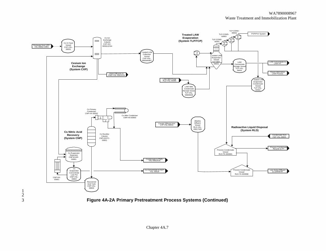
Chapter 4A.7
TLP-COND-00001
TLP-COND-00003
TLP-COND-00002
reated LAWEvaporator
VesselTLP-SEP-
00001
Cs IX FeedVessel
CXP-VSL-00001
Cs IonExchangeColumn
CXP-IXC-00001/2/3/4
Treated LAWCollection
VesselCXP-VSL-
00026A/B/CLAW
ConcentrateStorage Vessel
TCP-VSL-00001
LAW SBSCondensate
Receipt VesseTLP-VSL-00009A/B
reated LAWEvaporatorCondensate
VesselTLP-VSL-
00002
Process CondensateVessel
RLD-TK-00006A
Process CondensateVessel
RLD-TK-00006B
AlkalineEffluentVessel
RLD-VSL-00017A/B
CsEvaporator
ConcentrateLute Pot
CNP-VSL-00002
RecoveredAcid TankCNP-VSL-
00004
Cs EvaporatorSeparator
CNP-EVAP-00001
Cs After CondenserCNP-HX-00003
Cs PrimaryCondenser
CNP-HX-00002
Cs RectifierColumn
CNP-DISTC-00001
CNP-HX-00001
Radioactive Liquid Disposal(System RLD)Cs Nitric Acid
Recovery(System CNP)
Cesium IonExchange
(System CXP)
Treated LAWEvaporation
(System TLP/TCP)
Condensate fromFEP-VSL-00005
LAW Concentrate toLAW VIT
LAW SBS PurgeRLD-VSL-00005
Dilute Effluents toPWD-VSL-00015/16
Permeate from UFP-VSL-00062 A/B/C
Low Active Effluentto LERF/ETF
Cs Concentrate to HLP-VSL-00028
Condensate to PWD-VSL-00015/16
Process CondensateRecycle to PT
Caustic Effluent fromLVP-VSL-00001
Future AlternativeLAW Process
PVP/PVV System
1 2
Figure 4A-2A Primary Pretreatment Process Systems (Continued) 3
---------~ .... , ___ _,.

WA7890008967 Waste Treatment and Immobilization Plant
Chapter 4A.8
1 2
Figure 4A-3 Primary LAW Vitrification Systems 3
o- - :- ----, ~ '""° ! --""-,.-.... -•• ~:,--------------------------, ~ ,...__ _ __, LAW Melter Concentrate
j r,1:liirrc;;;;;nk-+l ___ __:R,::e:::c:::.e·:!,p::t.:&:..:P~r.::e~pa::r.:a::;tion Process (System LCP /LFP)
LAW Facility
0-o ____ _
LAW Melter Offgas Treatment(System LOP /LVP)
LV......OC.•O0OC>1 l~'!~ l~! lVP-sa-oo00J t.VP..SCMJOOOZ
Stet:

WA7890008967 Waste Treatment and Immobilization Plant
Chapter 4A.9
HMP-MLTR-00001HMP-MLTR-00002
Film CoolersHOP-FCLR-00001HOP-FCLR-00002
Glass FormerFeed Mixer
HLW MelterFeed Prep
VesselsHFP-VSL-00001-00005
Carbon BedAdsorber
H0P-ADBR-00002A/2B
SBSCondensate
VesselsHOP-VSL
-00903-00904
SBS ColumnsHOP-SCB-00001HOP-SCB-00002
WESPsHOP-WESP-00001HOP-WESP-00002
Stack
HLW MelterOffgas Treatment(System HOP)
HLW Melter ConcentrateReceipt & Preparation
Process (System HCP/HFP
Canisters
HLW MelterFeed
VesselsHFP-VSL-00002-00006
Pret
reat
men
t Fac
ility
Bala
nce
of F
acili
ties
HLW Facility
To PretreatmentPWD-VSL-00043
HydrogenPeroxide
HE
A
HE
A
HE
A
HE
A
TCO/SCR SkidsHOP-SKID-00005HOP-SKID-00007
AcidWasteVessel
RLD-VSL-00007
Note. 1 OffgasDrainsVessel
RLD-VSL-00002
2 MHNO3
CanisterDeconTank
HDH-VSL-00002-00004
Air Sparge
NeutralizationTank
HDH-VSL-00003
Air Sparge
H2O
Ceric Nitrate
HLW Melters
Plant Washand Drain
VesselRLD-VSL-
00008
Product CanisterDecontamination
(System HDH)
HeatExchanger
Vessel VentHeader
HEME
HEME
HOP-HEME-00001A/B
HOP-HEME-00002A/B
SilverMordeniteColumn
HOP-ABS-00002
HOP-ABS-00003
CanisterDeconBogieVessel
BoosterExtraction
Fans
StackExtraction
Fans
Pulse VentHeaders
HEPAs
HEPAs
ElectricHeater
HE
A
ElectricHeater HEPAs Extraction
Fan
Ammonia
ElectricHeater
HLWConcentrate from
Pretreatment
HDH-VSL-00001
To PretreatmentPWD-VSL-
00033/00043
1 2
Figure 4A-4 Primary HLW Vitrification Systems 3
11 11
~ -- 11 o- - _-_-___ .JI 11 11 11 11
11 11 11 11 11 11 11 11 11 1--11 r===__J ___ _
I 11r===-'---~
I 1--- 1 ---
11 11 11 11
__ I

WA7890008967 Waste Treatment and Immobilization Plant
Chapter 4A.10
SpentResinSlurryVessel
Cs ResinAdditionAir GapVessel
Cesium Resin AdditionProcess System (CRP)
Cs ResinAdditionVessel
Cs IonExchangeColumns
1
Resin / Caustic
Sodium Hydroxide
Demineralized WaterFresh Resin
Process Condensate toWaste Feed Evaporator
2
Caustic
Nitric Acid
Spent Reagents toRLD-VSL-00017A/B
Resin / Caustic
4
3
CXP-IXC-00001, CXP-IXC-00002,CXP-IXC-00003, CXP-IXC-00004are part of system CXP.Included here for clarity.
Legend
LiquidSlurry
1
2 RDP-VSL-0002A is a part of systemRDP. Included here for clarity.
3 CRP-VSL-00001
4 CRP-VSL-00002
1 2
Figure 4A-11 Cesium Resin Addition Process System (CRP) 3
c:::>
c:::> c:::> c:::>
L--·-·-·-·-·-·-·-·-·-·-·-·-·-·-,
c:::>

WA7890008967 Waste Treatment and Immobilization Plant
Chapter 4A.11
LAW MelterProcess System
LAW Locator: LMP
Pressure Control Air
Process Air
Sparge Bubbler Air
Air in - Leakage fromMelter Enclosure
Low Pressure Steam
Process Figure
Liquid
SlurryGas
Legend
Solid
Film CoolerLOP-FCLR-1/3
Primary
( Note 2 )
LAW Melter
ContainerContainer
Notes:1.There are 2 melters LAW-MLTR-00001/2 each with a dedicated feed vessel and submerged Bed Scrubber.2.Each Melter has a Primary ( LOP-FCLR-00001/3 ) and a Standby (LOP- FCLR-00002/4 ) Film Cooler.3.Glass is poured from discharge chambers to containers one at a time in an alternating sequence.
Film CoolerLOP-FCLR-2/4
Standby
( Note 2 )
See Note 1
To Submerged Bed Scrubber
To Submerged Bed Scrubber
Instrument Air
LAW Blended Melter Feed (6 nozzles feedmelter LFP VSL00002/4)
Note 3Note 3
1 2
Figure 4A-21 LAW Melter Process System (LMP) 3
,..__ ______ •------------------------------------------------------------• ' ' ' ' '
---------------------------------~L-____ ____...
~' ==========•----------------------------------------------------------.-n .__I ____ ____,•-----------------------------------------------------------.y
r-----.j ________ •
.___ _____ ..... . - . - . - . - . - . - . - _____________ !
....____ ___ • ---------------------------------------:
~------------------------------: l ._ ______________ _.,_ ' '
' '
•---------------------· ! l .______ : t . , 0 ..........................
• II
WA7890008967 Waste Treatment and Immobilization Plant
Chapter 4A.12
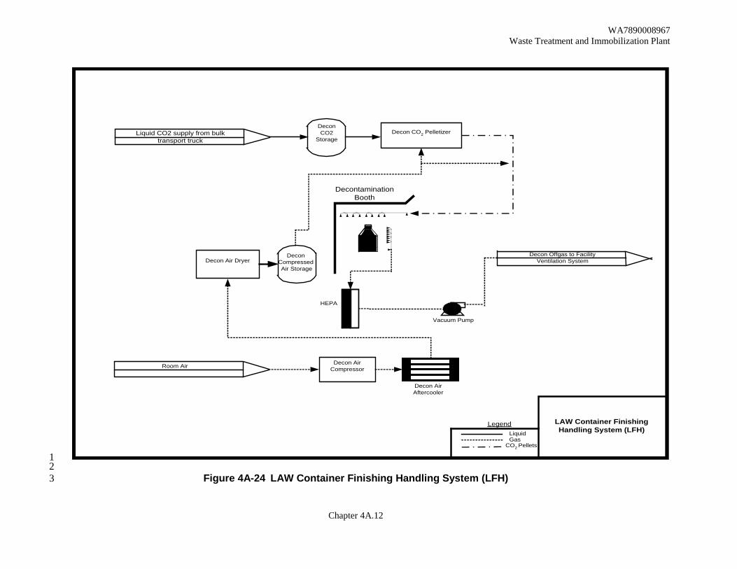
Decon Air Dryer
Decon CO2 Pelletizer
Decon Offgas to FacilityVentilation System
Liquid CO2 supply from bulktransport truck
DeconCompressed Air Storage
DecontaminationBooth
HEPA
Vacuum Pump
Decon AirCompressorRoom Air
Decon AirAftercooler
DeconCO2
Storage
Liquid
CO2 PelletsGas
Legend LAW Container FinishingHandling System (LFH)
1 2
Figure 4A-24 LAW Container Finishing Handling System (LFH) 3
~I~~ ~--·- ·1 .. -------------• I •-------------- . : I
r:::_ - ································:~·- - - -
lil'il''lli
:···' • ~ r
= -======--=Ll>--------------~L----1 ===-----
---------· t=t=======--==~--==-=-=il>

WA7890008967 Waste Treatment and Immobilization Plant
Chapter 4A.13
HLW MelterProcess System
HLW Locator HMP
Pressure Control Air
Film Cooler Air
Sparge Bubbler Air
Air in - Leakage(from Melter Cave)
HLW Blended Melter FeedHFP-VSL-00002/6
Process Figure
Liquid
SlurryGas
Legend
Solid
Film CoolerHOP-FCLR-00001/2
PrimaryNote 2
HLW MelterCanister Canister
To Submerged Bed Scrubber HOP-SCB-00001
Instrument Air
Note 3 Note 3
See Note 1
Notes:1.There are two Melters, HLW-MLTR -00001/2, each with a dedicated Melter Feed Vessel and Submerged Bed Scrubber2 Each HLW Melter has one Film Cooler and one standby.3.Glass is poured from discharge chambers to containers one at a time, in alternating sequence.
1 Figure 4A-27 HLW Melter Process System (HMP) 2
3
............................................................................. ! _____ _J. • ,············-······j
------------------•·····---------·········---------· iJi r------.__ _____ ........ __ _ _
~ - ·- · - · - ·
11:=1 ========~ .. ·····································i ~========~::::::::::::::::::::::~········1 i r······················J
. ' + ! =

WA7890008967 Waste Treatment and Immobilization Plant
Chapter 4A.14
1 2
3 This page intentionally left blank. 4
5

WA7890008967 Waste Treatment and Immobilization Plant
Chapter 4A.15
1 Figure 4A-38 Typical Tank System – Cesium Ion Exchange Column 2
3
Vapor Space Vessel Wash Reagents
Resin Addition
LAW Addition
reated LAW to Process
Spent Resin
Vessel Vent
Drain to Recycle
Supports
Hot Cell Wall
Wa l Penetrations
L L
Level Measurement Steam Ejector
Screen
Rad Monitor
High High emp
Interlock
Ch lled Water Supply
Chil ed Water Return
Wa l Penetration
Wall Penetration
Purge Air Resin F ush
Screen
Sta nless Steel Liner and/ or Protective Coat ng
Construction oint
Typical Tank System - Cesium Ion Exchange Column
Protective Coat ng
,,
\ ...

WA7890008967 Waste Treatment and Immobilization Plant
Chapter 4A.16
1 2 3
This page intentionally left blank. 4 5

WA7890008967 Waste Treatment and Immobilization Plant
Chapter 4A.17
1 2
Figure 4A-48 Typical System - LAW Melter Process System (LMP) 3
Refractory
Plenum
Cold Cap
Melt Pool
Heating Electrode
0 0
0 0
Feed
6
Melt Pool
Not to scale
Airlift
Plenum
Discharge Throat
Q
0
a
Glass Container
Discharge Chamber
Discharge Trough
Airlift Riser
WA7890008967 Waste Treatment and Immobilization Plant
Chapter 4A.18
1 2
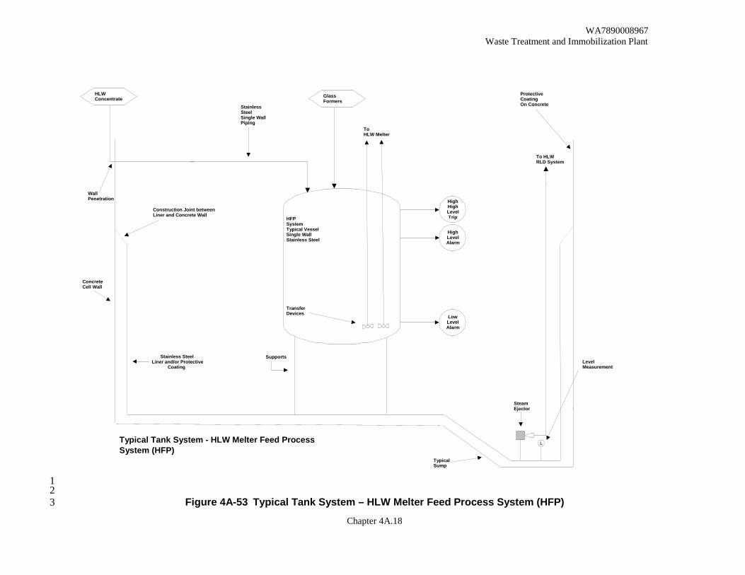
Figure 4A-53 Typical Tank System – HLW Melter Feed Process System (HFP) 3
HFP System Typical Vessel Single Wall Stainless Steel
Transfer Devices
Stainless Steel Liner and/or Protective
Coating
HLW Concentrate
Wall Penetration
Stainless Steel Single Wall Piping
Concrete Cell Wall
Construction Joint between Liner and Concrete Wall
High Level Alarm
Typical Sump
Steam Ejector
Protective Coating On Concrete
Supports
L
Level Measurement
To HLW Melter
High High Level Trip
Low Level Alarm
To HLW RLD System
Glass Formers
Typical Tank System - HLW Melter Feed Process System (HFP)
l
•-

WA7890008967 Waste Treatment and Immobilization Plant
Chapter 4A.19
1 Figure 4A-59 Typical System - Containment Building (Sheet 1) 2
3
Shield Windows(Sealed)
MSM Penetrations(Sealed)
Through Wall Drives(Sealed)
Container
Rotate Stand
In - CellCrane
Grab
Container
SwabbingMachine
SwabContainer
SwabContainer
HighActive
Swab entry point
Steel-reinforcedConcrete Walls andCeilings
Stainless SteelLiner and/orProtective Coating
Steel-reinforcedConcrete Foundation
Welded Seam
Welded Seam
Sealed ConstructionJoint
To HEPA Filtration
Airflow Directionto MaintainNegativePressure
Import and ExportHatches with Air FlowSeals
Shield Door
Air Flow Direction Containment
Typical System - Containment Building
I i.,.,:·····.:: . .···:··~·-.:,:.·rv .. ,: ~-. 1-.;·:::::::::::::::::i ·- :·· ..
c::============~: t::::::=::• ===================1, i .. £ / i/
•.
1 ~-- .lL ,, _J, 12r·-l::::1 n······n ,.:.-.-
11 ........................... n:r
1~[ .............. -...... J ......... r::r::: :::::::J
r_LL ...... Ll.1 l l _ :--: _.--=
.....-------,-··---------------------· ~·- (______.___________,r···· L. ..... ...l ····: • ..,____----! ........... i··i·······'
.........._ __ i:::::::----,=il:---~\.. ........ -.. 1 ......
I
\

WA7890008967 Waste Treatment and Immobilization Plant
Chapter 4A.20
1 2 3
This page intentionally left blank. 4 5
WA7890008967 Waste Treatment and Immobilization Plant
Chapter 4A.21
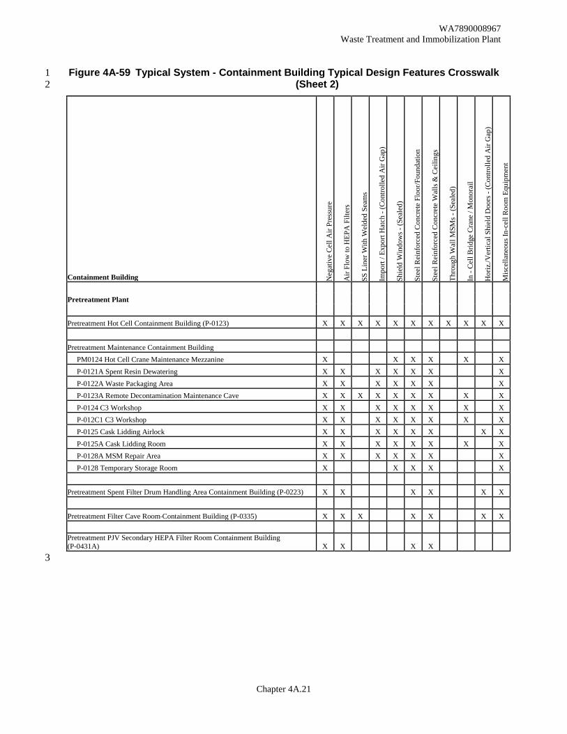
Figure 4A-59 Typical System - Containment Building Typical Design Features Crosswalk 1 (Sheet 2) 2
Containment Building Neg
ativ
e Ce
ll A
ir Pr
essu
re
Air
Flow
to H
EPA
Filt
ers
SS L
iner
With
Wel
ded
Seam
s
Impo
rt / E
xpor
t Hat
ch -
(Con
trolle
d A
ir G
ap)
Shie
ld W
indo
ws -
(Sea
led)
Stee
l Rei
nfor
ced
Con
cret
e Fl
oor/F
ound
atio
n
Stee
l Rei
nfor
ced
Con
cret
e W
alls
& C
eilin
gs
Thro
ugh
Wal
l MSM
s - (S
eale
d)
In -
Cell
Brid
ge C
rane
/ M
onor
ail
Hor
iz./V
ertic
al S
hiel
d D
oors
- (C
ontro
lled
Air
Gap
)
Misc
ella
neou
s In-
cell
Room
Equ
ipm
ent
Pretreatment Plant Pretreatment Hot Cell Containment Building (P-0123) X X X X X X X X X X X Pretreatment Maintenance Containment Building PM0124 Hot Cell Crane Maintenance Mezzanine X X X X X X P-0121A Spent Resin Dewatering X X X X X X X P-0122A Waste Packaging Area X X X X X X X P-0123A Remote Decontamination Maintenance Cave X X X X X X X X X P-0124 C3 Workshop X X X X X X X X P-012C1 C3 Workshop X X X X X X X X P-0125 Cask Lidding Airlock X X X X X X X X P-0125A Cask Lidding Room X X X X X X X X P-0128A MSM Repair Area X X X X X X X P-0128 Temporary Storage Room X X X X X Pretreatment Spent Filter Drum Handling Area Containment Building (P-0223) X X X X X X Pretreatment Filter Cave Room Containment Building (P-0335) X X X X X X X Pretreatment PJV Secondary HEPA Filter Room Containment Building (P-0431A) X X X X 3

WA7890008967 Waste Treatment and Immobilization Plant
Chapter 4A.22
Containment Building Neg
ativ
e Ce
ll A
ir Pr
essu
re
Air
Flow
to H
EPA
Filt
ers
SS L
iner
With
Wel
ded
Seam
s
Impo
rt / E
xpor
t Hat
ch -
(Con
trolle
d A
ir G
ap)
Shie
ld W
indo
ws -
(Sea
led)
Stee
l Rei
nfor
ced
Con
cret
e Fl
oor/F
ound
atio
n
Stee
l Rei
nfor
ced
Con
cret
e W
alls
& C
eilin
gs
Thro
ugh
Wal
l MSM
s - (S
eale
d)
In -
Cell
Brid
ge C
rane
/ M
onor
ail
Hor
iz./V
ertic
al S
hiel
d D
oors
- (C
ontro
lled
Air
Gap
)
Misc
ella
neou
s In-
cell
Room
Equ
ipm
ent
LAW Vitrification Plant LAW LSM Gallery Containment Building (L-0112) X X X X X X ILAW Container Finishing Containment Building L-0109B Swabbing Cell North Line X X X X X X X X X X L-0109C Decontamination Area North Line X X X X X X X X X X L-0109D Inert Fill / Welding Area North Line X X X X X X X X X X L-0115B Swabbing Cell South Line X X X X X X X X X X L-0115C Decontamination Area South Line X X X X X X X X X X L-0115D Inert Fill / Welding Area South Line X X X X X X X X X X L-0109E Container Monitoring/Export Area - North Line X X X X X X X X X X L-0115E Container Monitoring/Export Area - South Line X X X X X X X X X X LAW Vit Plant C3 Workshop Containment Building (L-226A) X X X X X X LAW Consumable Import/Export Containment Building (L-0119B) X X X X X X LAW Pour Cave Containment Building L-B015A Pour Cave (Melter 1) X X X X X X X X X X L-B013C Pour Cave (Melter 1) X X X X X X X X X X L-B013B Pour Cave (Melter 2) X X X X X X X X X X L-B011C Pour Cave (Melter 2) X X X X X X X X X X L-B011B (Spare) X X X X X X X X X X L-B009B (Spare) X X X X X X X X X X ILAW Container Buffer Storage Containment Building
L-B025C L-B025D
1

WA7890008967 Waste Treatment and Immobilization Plant
Chapter 4A.23
Containment Building Neg
ativ
e Ce
ll A
ir Pr
essu
re
Air
Flow
to H
EPA
Filt
ers
SS L
iner
With
Wel
ded
Seam
s
Impo
rt / E
xpor
t Hat
ch -
(Con
trolle
d A
ir G
ap)
Shie
ld W
indo
ws -
(Sea
led)
Stee
l Rei
nfor
ced
Con
cret
e Fl
oor/F
ound
atio
n
Stee
l Rei
nfor
ced
Con
cret
e W
alls
& C
eilin
gs
Thro
ugh
Wal
l MSM
s - (S
eale
d)
In -
Cell
Brid
ge C
rane
/ M
onor
ail
Hor
iz./V
ertic
al S
hiel
d D
oors
- (C
ontro
lled
Air
Gap
)
Misc
ella
neou
s In-
cell
Room
Equ
ipm
ent
HLW Vitrification Plant HLW Melter Cave 1 Containment Building: X X X X X X X X X X X H-0117 Melter Cave 1 X X X X X X X X X X X H-0116B Melter Cave 1 - C2/C3 Airlock X X X X X H-0310A Melter Cave 1 Equipment Decon Pit X X X X X X X X X X HLW Melter Cave2 Containment Building: X X X X X X X X X X X H-0106 Melter Cave 2 X X X X X X X X X X X H-0105B Melter Cave 2 - C2/C3/ Airlock X X X X X X 1 H-0304A Melter Cave 2 Equipment Decontamination Area X X X X X X X X X X IHLW Canister Handling Cave Containment Building (H-0136) X X X X X X X X X X X
IHLW Canister Swab and Monitoring Cave Containment Building (H-0133) X X X X X X X X X C3 Workshop Containment Building: X X X X X C3 Workshop (H-0311A) X X X X X C3 MSM Maintenance Workshop (H-0311B) X X X X HLW Filter Cave Containment Building (H-0104) X X X X X X X X X X HLW Waste Handling Area Containment Building: X X X X H-0410B E&I Room X X X X H-0411 Waste Handling Room X X X X HLW Pour Tunnel 1 Containment Building (H-B032) X X X X X X X HLW Pour Tunnel 2 Containment Building (H-B005A) X X X X X X X HLW Drum Swabbing and Monitoring Area Containment Building: X X X X X H-0126A Crane Maintenance Room X X X X H-0126B Swabbing and Monitoring Room X X X X H-B028 Cask Import/Export Room X X X X X 1 2

WA7890008967 Waste Treatment and Immobilization Plant
Chapter 4A.24
1 2 3
This page intentionally left blank. 4 5

WA7890008967 Waste Treatment and Immobilization Plant
Chapter 4A.25
1 Figure 4A-65 Simplified General Arrangement Pretreatment - Plan at El. 98 2
Some information, on this page, may appear to be illegible; however, the information necessary for assuring adequate design is legible 3
---
0
C
-.,'C.
,,
r,
Ptll'lU,. Pl~II ,:' l. (L 11!1 ~t,
~b .,.,.,.,.~=-=-· ::r
•
,, _:r
:..."-
J ) r
..... .,. ttl.lRW)) PA· flM.. F\_.111( '8" ,,.-r £t ts'·O"
• •
Ld=,, ~
...... J "1))0
.•.
,i,1'1111. •JTU, '---'==-----I ,..., ________ G
~,,,.a'"" _____ _
. ~.,;:::-'-----·-. --~ !?~~1."J$9~~-
1= -
----·· --~---·-----·--------·-----____ ....,,. ____ _ :;-;~·-·· ..... J
-----""- ----
·-----·--... --·--...... ..
~-------.~"!'"~"."~"_"_,..,..._ ;cl.~
---
0
C
•

WA7890008967 Waste Treatment and Immobilization Plant
Chapter 4A.26
1 Figure 4A-118 Schematic of an Example IHLW Container and Label 2
Some information, on this page, may appear to be illegible; however, the information necessary for assuring adequate design is legible 3
CD HLW CANISTER DETAIL
DETAILK SCALE: 1:2
(APPLIES 2 PLACES) CANISTER NUMBER
SANS SERIF HELVETICA CMEGARON) MEDIUM FULL WIDTH TYPICAL IDENTIFICATION WELD
SEE 24590-HLW-MX-30-00010001
AND 24590-HLW-MX-30-00010003
VIEW J-J SCALE= NTS
1- SEE DETAIL K I
I
R 9.125 :!:.250

WA7890008967 Waste Treatment and Immobilization Plant
Chapter 4A.27
1 Figure 4A-119 Schematic of an Example ILAW Container and Label 2
Some information, on this page, may appear to be illegible; however, the information necessary for assuring adequate design is legible 3 4
7 A
_l_.080A
"'"" JJ )' xxxxx
.. ,,ll '-.12
2.00 .00
1.40 00
DETAIL SCALE-½"- 7
CONTAINEEiANRUOMNBEJEoT1i~lC/&LL2xWIDTH SANS SERIF M
VIEW A-A SCALE, 1/~" = 7"
SECTION B-B SCALE:½"- 1"

WA7890008967 Waste Treatment and Immobilization Plant
Chapter 4A.28
1 2 3
This page intentionally left blank. 4 5

WA7890008967 Waste Treatment and Immobilization Plant
Chapter 4A.29
RFD CONTROLSYSTEM
PI
PT PT
compressedair/gas
‘Y’ typestrainer
pressureregulator
pressure indicator
primary automaticisolation valve
secondary automaticisolation valve
needle valve
pressure transducer
manual isolation
‘Y’ type strainer
suction/drive jet pump pair
charge vessel
RFD
to deliveryvessel
supply vessl
A B
0300.doc
1 Figure 4A-120 Typical Arrangement of a Reverse Flow Diverter 2
Some information, on this page, may appear to be illegible; however, the information necessary for assuring 3 adequate design is legible 4 5

WA7890008967 Waste Treatment and Immobilization Plant
Chapter 4A.30
1 2 3
This page intentionally left blank. 4 5
WA7890008967 Waste Treatment and Immobilization Plant
Chapter 4A.31
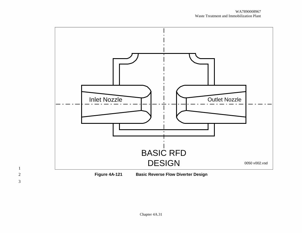
BASIC RFDDESIGN
Inlet Nozzle Outlet Nozzle
0050 v002.vsd 1
Figure 4A-121 Basic Reverse Flow Diverter Design 2
3
1,; \..'"
~ r ~ \..._
·------------ - ------ -- ------------I
" I r I ~ -I \... I I
I
I

WA7890008967 Waste Treatment and Immobilization Plant
Chapter 4A.32
1 2 3
This page intentionally left blank. 4 5

WA7890008967 Waste Treatment and Immobilization Plant
Chapter 4A.33
STEAMSUPPLY
VENT AIRSUPPLY
ACTUATOR
3 WAY VALVE
TO CELL ORVESSEL VENT
SYSTEM
TO OTHERVALVES
NRV
STEAM VALVE CABINET
C2 ORC3 AREA
40 mm - 50 mm n.b.
25 mm n.b. 15mmn.b.
Backupconnection
MINIMUM HEIGHTTO BE AT LEAST 1
BAROMETRICHEAD OF FLUID
ABOVE A LIFT ANDFORCE EJECTOROR THE MAXIMUM
FLUID LEVEL INTHE SUPPLY
VESSEL FOR ASUBMERGED
EJECTOR
BREAKPOT
DELIVERY VESSEL
VENTSYSTEM
VENT SYSTEM
SUPPLY VESSEL
HIGHEST DISCHARGE POINT
VENT SYSTEM
C4 OR C5 CELL
TYPICALARRANGEMENT OF A
STEAM EJECTORSYSTEM
STEAM SUPPLY PIPE
EJECTORDELIVERY PIPE
EJECTORSUCTION PIPE
END OF SUCTION PIPEOR MIN MUM FLUID
LEVEL
BREAK POTDISCHARGE PIPE
ALTERNATIVESUBMERGED
EJECTOR
LIFT ANDFORCE
EJECTOR
OVERFLOW
VAC. BREAKVALVE
Needle valve lockedopen to assure in-bleed
on failure of vent airsupply air
0051 v002.vsd 1 Figure 4A-122 Typical Arrangement of a Steam Ejector System 2
3

WA7890008967 Waste Treatment and Immobilization Plant
Chapter 4A.34
1 Figure 4A-123 Typical Seal Pot Arrangement 2
3
VENT
FEED
VENT
SEAL
SEAL POT

WA7890008967 Waste Treatment and Immobilization Plant
Chapter 4A.35
1 2
Figure 4A-124 Typical Breakpot Arrangement 3
VESSEL SUPPORT
VESSEL VENT
PROCESS OUTLET
DISENTRAINMENT (PACKED) SECTION
PROCESS INLET
OVERFLOW
0052 v002.ppt

WA7890008967 Waste Treatment and Immobilization Plant
Chapter 4A.36
1 Figure 4A-127 Typical Bulge Configuration 2
3
,_-\ 'mt flller
(T•p Vk"')
.......
(Sldt Vkw)

WA7890008967 Waste Treatment and Immobilization Plant
Chapter 4A.37
1 2 3 4 5 6 7 8 9 10 11 12 13 14 15 16 17 18 19 20 21 22 23 24 25 26 27 28 29 30 31 32 33 34
Figure 4A-128 Typical Primary Containment Sump Conceptual Design 35
A A
SECTION A-A
B B
SECTION B-BSECONDARYSUMP(EXSTING)
PRIMARYSUMP
D D
Leak Detection Probe
Primary Sump
Secondary Sump

WA7890008967 Waste Treatment and Immobilization Plant
Chapter 4A.38
1 2 3
This page intentionally left blank. 4 5