
Waste Retrieval Project G. R. Tardiff For approval and .../67531/metadc737905/m2/1/high... · CCTV...
131
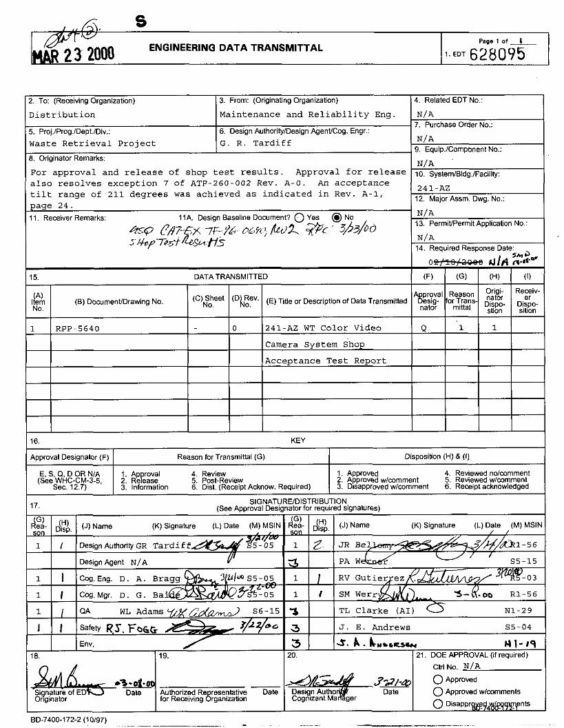
~.EDT 628095 ENGINEERING DATA TRANSMITTAL - % 2000 Waste Retrieval Project G. R. Tardiff For approval and release of shop test results. Approval for release also resolves exception 7 of ATP-260.002 Rev. A-0. An acceptance tilt range of 211 degrees was achieved as indicated in Rev. A-1, &Q P#7.& 7F-% 0LX; bd s./+#p$+ &S‘&3 (6) DocumenVDrawingNo. Approval Designator (F) Reason for Transmittal (G) Disposition (H) & (I) E S Q D OR N/A 1. Ap (oval 4. Review 1. Approved 4. Reviewed ndcnmment (See’WhC-CM-3-5. 2. Rekase 5. Post-Review 2. Approved wlcomment 5. Reviewed wlcomment Sec. 12.7) 3. Information 6. Dist. (Receipt Acknow. Required) 3. Disapproved wlcomment 6. Receipt acknowledged SIGNAT! 17. (See Approval Desi (K) Signature (L) Date (M) MSlh %05 a& 1 I Design AuthorilyGR Tardiff Desian Aaent NfA P I 18. 119. Authorized Re resenlative Date for Receiving Brganization ED-7400-172-2 (10197) EIDISTRIBUTION lator for required signatures) F ! % I $A I (J)Name (K) Signature (L) Date (M) MSlN 1 I I RV GutierJez 3 TL Clarke (AI) 0 Nl-29 3 J. E. Andrews S5-04 3 3. b . I C . . , , - H1-m 20. 21. DOE APPROVAL (if required) Ctrl NO. N/A
Transcript of Waste Retrieval Project G. R. Tardiff For approval and .../67531/metadc737905/m2/1/high... · CCTV...
~ . E D T 628095 ENGINEERING DATA TRANSMITTAL -% 2000
Waste Retrieval Project G. R. Tardiff
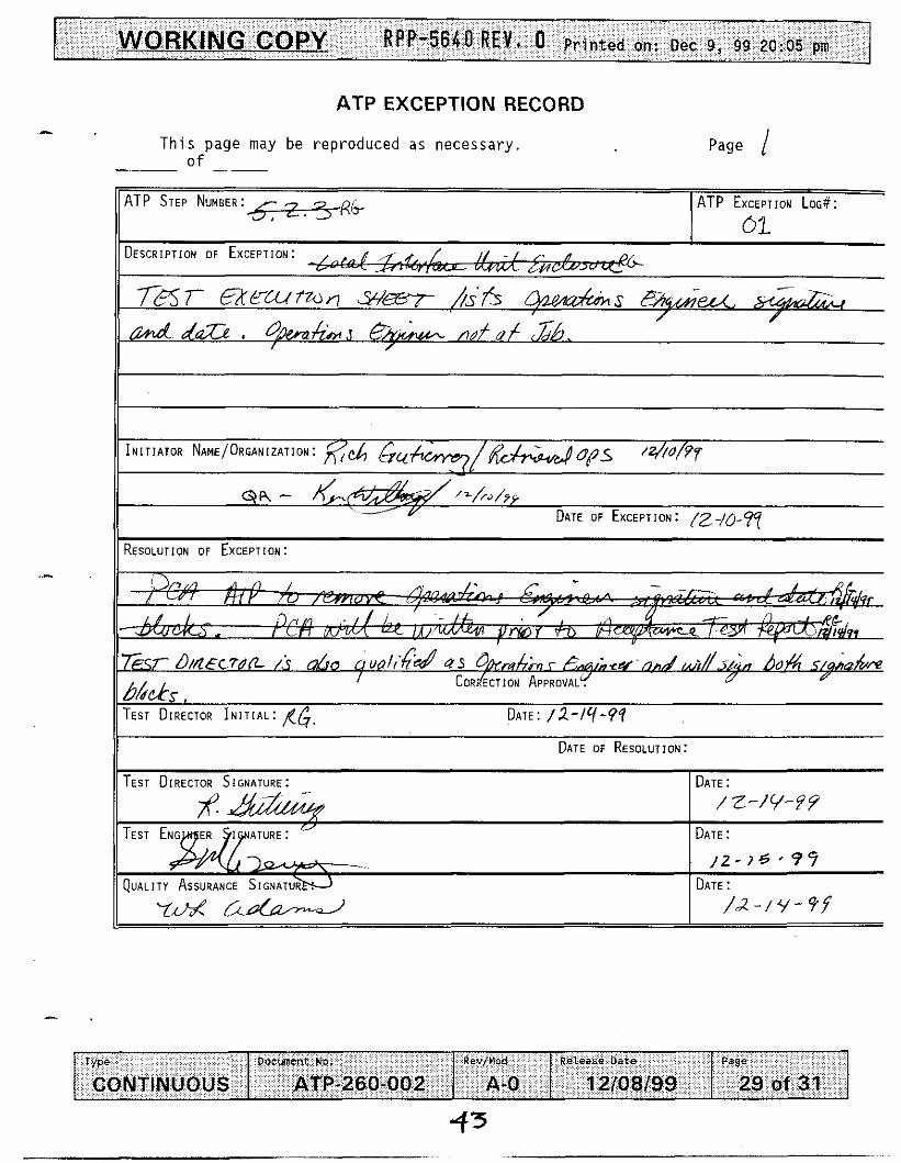
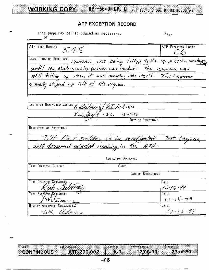
For approval and release of shop test results. Approval for release also resolves exception 7 of ATP-260.002 Rev. A-0. An acceptance tilt range of 211 degrees was achieved as indicated in Rev. A-1,
&Q P#7.& 7 F - % 0LX; b d s . / + # p $ + &S‘&3
( 6 ) DocumenVDrawing No.
Approval Designator (F) Reason for Transmittal (G) Disposition (H) & ( I )
E S Q D OR N/A 1. Ap (oval 4. Review 1. Approved 4. Reviewed ndcnmment (See’WhC-CM-3-5. 2. Rekase 5. Post-Review 2. Approved wlcomment 5. Reviewed wlcomment
Sec. 12.7) 3. Information 6. Dist. (Receipt Acknow. Required) 3. Disapproved wlcomment 6. Receipt acknowledged
SIGNAT! 17. (See Approval Desi
(K) Signature (L) Date (M) MSlh
%05 a&
1 I Design AuthorilyGR Tardiff
Desian Aaent NfA P
I
18. 119.
Authorized Re resenlative Date for Receiving Brganization
ED-7400-172-2 (10197)
EIDISTRIBUTION lator for required signatures)
F!% I $A I (J)Name (K) Signature (L) Date (M) MSlN
1 I I RV GutierJez
3 TL Clarke (AI) 0 Nl-29
3 J. E. Andrews S5-04
3 3. b . IC..,,- H 1 - m 20. 21. DOE APPROVAL (if required)
Ctrl NO. N/A
RPP-5640, Rev. 0
241 -AZ-l 01 Waste Tank Color Video Camera System Shop Acceptance Test Report
3 . M . Werry CH2MHill Hanford Group, Inc. Richland. WA 99352 U.S. Department of Energy Contract DE-AC06-96RL13200
EDTIECN: 628095 u c : Ow Code: 7 4 6 0 0 Charge Code: 112447
Code: EW02J119 Total Pages: 129
Keywords: Waste Tank, Color Video Camera System, AZ-101
Abstract: This report includes shop acceptance test results. The test was performed prior to installation at tank AZ-101. Both the camera system and camera purge system were originally sought and procured as a part of initial waste retrieval project W-151.
TRADEMARK DISCLAIMER. Reference herein to any specific commerdal product, process, or service by trade name, trademark, manufadurer, or otherwise. does not necessarily wnstiiute or imply its endorsement, remmmendatbn. or favoring by the United States Government or any agency thereof or its contractors or subcontractors.
Pnnted in the Uniied Slates of Ameroa To 0bta.n wples of this document, contact Docbrnenl Control Services, P 0 Box 950. Ma,lstop e508 Rhnand WA 99352, Phone (509) 372-2420. Fax (509) 3764989
I - o
Approved For Public Release
RPP-5640
Rev. 0
241-AZ-101 WASTE TANK COLOR VIDEO CAMERA SYSTEM SHOP ACCEPTANCE TEST REPORT
S. M. Weny
CH2MHill Hanford Group, Inc. RPP Maintenance & Reliability Engineering

RF’P-5640 REV . 0
AZ-101 CAMERA SHOP ACCEPTANCE TEST REPORT
TABLE OF CONTENTS
1.0 INTRODUCTION .............................................................................................. 3
2.0 TEST EQUIPMENT DESCRIPTION AND TEST SUMMARY .................. 3
2.1 EQUIPMENT DESCRIPTION ............................................................. 3
2.2 SUMMARY ............................................................................................. 3
3.0 TEST PROCESS ................................................................................................ 4
4.0 TEST CONCLUSIONS ...................................................................................... 5
5.0 ATTACHMENT 1 -TEST PERFORMANCE TABLE ................................. 6
6.0 ATTACHMENT 2 . ATP-260-002 REV . A.0, TEST PHASE 1 ................... 13
7.0 ATTACHMENT 3 . ATP-260-002 REV . A.0, TEST PHASE 2 ................... 55
8.0 ATTACHMENT 4 . ATP-260-002 REV . A.1, TEST PHASE 3 ................... 91
9.0 ATTACHMENT 5 . MACRO SCALE MEASUREMENTS USING CCTV MICROMETER, S . WERRY. D . DOUGLAS TO A . CARLSON. JANUARY. 2000 ............................................................................................. 127
2

RPP-5640 Rev. 0
AZ-101 CAMERA SYSTEM SHOP ACCEPTANCE TEST REPORT
1.0 INTRODUCTION
During the months of December (1999) and January (2000), a Shop Acceptance Test was performed on the tank AZ-101 in tank camera and camera purge systems. Testing was performed at both the 2703E and 2715E facilities located in 200 East area. This report documents the results of the testing. A general overview of the imaging system and original developmental methodology is described in Engineering Task Plan WHC-SD-WI 5 1 -ETP-001.
2.0 TEST EQUIPMENT DESCRIPTION AND TEST SUMMARY
2.1 Equipment Description
In calendar year 1995, a two camera and camera purge system were specified, designed, and procured for waste tank AZ-101 as a part of waste retrieval project W-151. The two camera system was designed to provide visual information for assessment of the upper dome space region within tank AZ-101 and in addition to monitoring dome intrusive activities within the tank. Both camera and mast assemblies include an upper junction box for cable and purge interfacing , flange adapter fixture, mast, pan & tilt, lights, and camera. The 550 camera was designed for weld inspection and is not a part of this test. The 55 1 camera used for this test is an overview type camera which provides a 22mm to 90mm zoom lensing capability. The system also includes a portable camera purge system which provides a NFPA type X purge in addition to camera cooling. The system, including both camera assemblies, was previously tested in July of 1996.
2.2 Summary
Since previous testing was performed 1996, new in tank viewing parameters were identified and a retest of the camera and purge system was requested. The restest focused first on, providing verification the RCS-551 overview camera design could capably meet the new in tank viewing requirements and second, an opportunity to ensure all of the camera system test processes followed were in alignment with the tank farm FSAR which was released earlier in 1999. The retest was performed in December of 1999 and the results are published herein.
WP-5640 Rev. 0
3.0 TEST PROCESS
The test processes were performed in both the 2703 and the 2715 buildings located in the 200 East area. Prior to beginning the test, a series of simulated in tank fixtures and equipment were fabricated. During the test, the fixtures were placed at predetermined distances and positions for strategic location in relation to the camera and tank riser layout. Simulated internal tank environmental conditions were employed "as much as possible" during the test process. The test fixtures were placed and moved attempting to reflect minimum equipment deflection which may occur during operation of AZ-IO1 mixer pump operation. The test equipment fixtures consisted of a simulated carbon steel tank background fixture and three simulated in tank equipment target fixtures. The target equipment fixtures were placed between the camera and simulated in tank background test fixture while the 551 camerahast assembly was suspended vertically using an overhead approximately 1.1 ton overhead lifting devise. The assembly was secured to a special test flange fixture which was temporarily located on the upper level structure of 2703 framework.
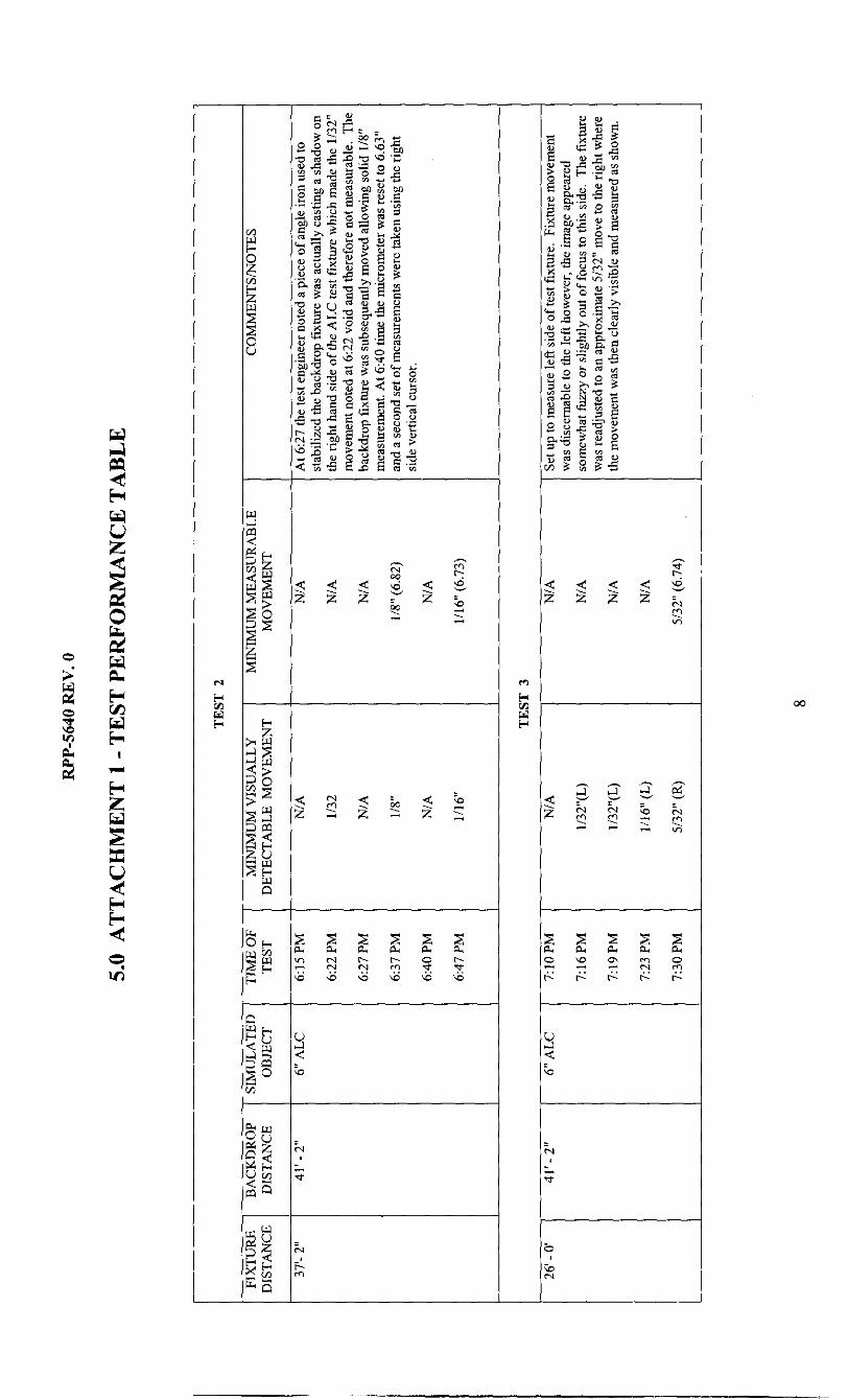
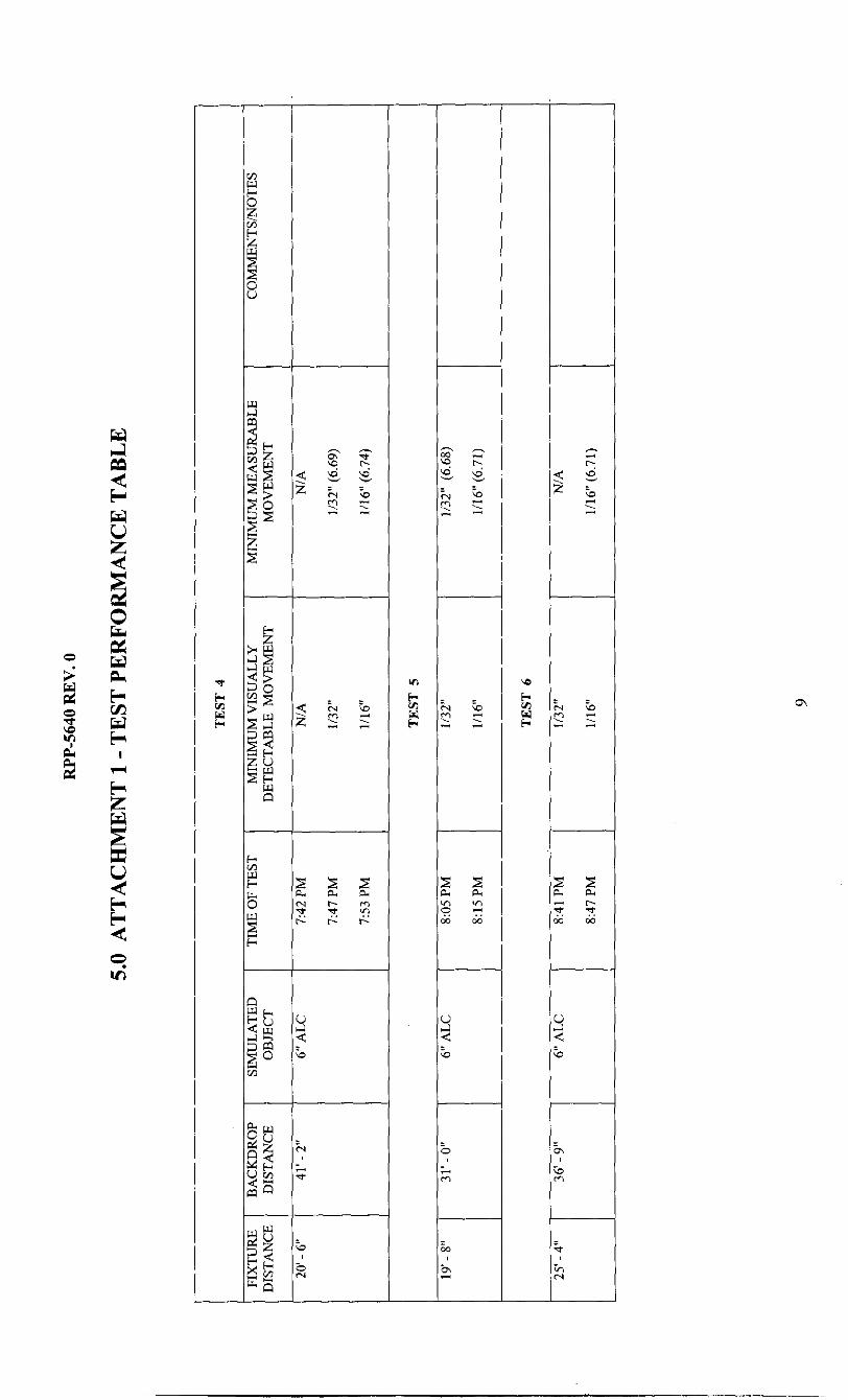
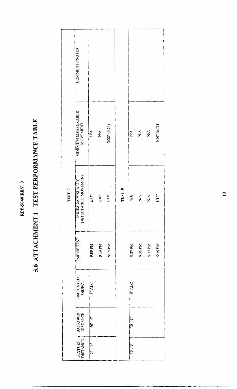
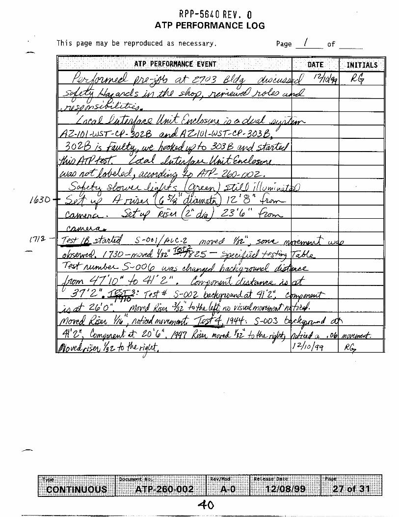
The test was conducted in three phases. During performance of the test, building lights were turned off simulating (as near as possible) the very dark ambient lighting conditions within tank AZ-101. Lighting was adjusted periodically as needed to accommodate both test personnel safety and assure camera system test lighting conditions remained as dark as possible. During each phase of the test, the simulated in tank test fixtures were moved in 1/32nd of an inch increments and measured both visually and electronically using a video micrometer. The results of the incremental movement testing and two final discretionary tests are provided in the attached test performance table (ref. attachment 1).
During test phase one (ref. attachment 2), some typographical errors and equipment exceptions were noted which warranted a retest. Test phase two (ref. attachment 3) corrected and resolved equipment exceptions noted in phase 1 while test procedure revision A-I corrected the typographical errors. Test phase three (ref. attachment 4) was required in order to test a back up pan and tilt which was placed in service after the original pan and tilt unit failed. The failure cause, although not specifically identified, was traced to a dual system interface location and isolated. No problems were encountered with the replacement pan and tilt during testing. Since the camera system was originally a two camera dual phase design, continued operation based on a single phase (one specific camera) operation was unilaterally perceived as acceptable and testing was successfully completed. The failed pan and tilt was shipped back to the Vendor for repair, repaired, and is now maintained as a spare.
4
-
RPP-5640 Rev. 0
4.0 TEST CONCLUSIONS
At conclusion of acceptance testing, all parties involved in the shop acceptance test activity agreed the shop acceptance test was successful and approval signatures were garnered. This concurrence of approval, concludes the shop acceptance testing process for the AZ-101 camera and camera purge system. Upon release of the results in this test report, shop test procedure requirements as delineated in TWRS Administrative Procedure, IP-8042, are satisfied and the system is now ready for field installation and operational testing.. It should also be noted, Vista Engineering Technologies, provided input to the test measurement process and reviewed test results independently. Vistas' approval and noted coiiclusions are attached and can be found in section 9.0 ATTACHMENT 5.
&*-i- RF'P Maintenance and Reliability Eng.
5

RPP-5640 REV. 0
5.0 ATTACHME" 1 - TEST PERFORMANCE TABLE
6
_I

e
z w c j
... U
I
?

-l--
1 3

I I
m N c!
r 2 3
1.
..

RPP-5640 REV. 0
6.0 ATTACHMENT 2 - ATP-260-002 REV. A-0, TEST PHASE 1
13

WORKING COPY
TANK FARM ACCEPTANCE TEST PROCEDURE
Pr in ted on: Dec 9, 99 20:05 pm
241 -AZ SHOP ATP ,-
Last F u l l Revision: A-0
Release Date: 12/08/99
USQ Screening Number: N/A
Approval Desi gnator : SQ
Current M o d i f i c a t i o n : A-0
USQ Screening Number: N/A
Approval Designator: SQ PCA Incorporated: N/A
POSITION/ORG DELEGATE DATE
*U”IwTJ V i c k i Miller 12/7/99
R. G u t i e r r e z 121a/99
!am W.L. Adam i z / a / g g
SAFTEY E r n i e H u r s t 121~199
TWRS Rad Con Bob Brown 12 18/99
Envi ornrnental T.A. D i l h o f f i21a199
COQ Equip. Ens. R . Robinson 12 18/99
Acceptance Review Dav id W . VanDvke 121~199
Approval A u t h o r i t y James Bryce 121~199
COQ Enq/DST Gary T a r d i f f 12/7/99
J u s t i f i c a t i o n : New Procedure.
Summary o f Changes: N/A
R P P - 5 6 4 0 REV1 0
TYPO O o c w n t bo. Rcv/Hod ReIoasc Dale
CO NTlN U OU S ATP-260-002 A-0 12/08/99
I 241-A2 WASTE TANK COLOR VIDEO CAMERA SYSTEM SHOP ACCEPTANCE TEST PROCEDURE
Page
1 of 31
WORKING COPY - 0 R E V , 0 Printed on: Dec 9, 99 20:05 pin
TYP@
CONTINUOUS
c_ TABLE OF CONTENTS PAGE TEST EXECUTION SHEET . . . . . . . . . . . . . . . . . . . . . . . . . . 3
DocUnenT No. REvJMod Pc.caSe Date Page
ATP-260-002 A-0 12/08/99 2 of 31
1.0 PURPOSE AND SCOPE 4 1.1 PURPOSE 4 1 . 2 S C O P E . . 4
. . . . . . . . . . . . . . . . . . . . . . . . . . . . . . . . . . . . . . . . . . . . . . . . . . . . . . . . . . . . . . . . . . . . . . . . . . . . . . .
. . . . . . . . . . . . . . . . . . . . . . . . . . . . 4 2 . 0 INFORMATION 2 . 1 TERMS AND D E F I N I T I O N S 4 2 . 2 R E S P O N S I B I L I T I E S 4
. . . . . . . . . . . . . . . . . . . . . . . . . . . . . . . . . . . . . . . . . . . .
. . . . . . . . . . . . . . . . . . . . . . . . . .
. . . . . . . . . . . . . . . . . . . . . . . . . . 2 . 3 REFERENCES 6 2 . 4 R E C O R D S . . 6
3 . 0 PRECAUTIONS AND L IMITATIONS . . . . 3 . 1 PERSONNEL SAFETY . . . . . . .
1 .
. . . . . . . . 7 . . . . . . 7
. . . . . . . . . . . . . . . . . . . . . . . . . . . 4 . 0 PREREQUISITES 8 4 . 1 SPECIAL TOOLS, EQUIPMENT, AND SUPPLIES 8 4 . 2 CONDITIONS AND ACTIONS 9
. . . . . . . . . . . . . . . . . . . . . . . . . . . . . . . .
5 . 0 PROCEDURE . . . . . . . . . . . . . . . . . . . . . . . . . . . . . 10 5 . 1 START UP AND PURGE SYSTEM TEST . . . . . . . . . . . . . . . . 10 5 . 2 PURGE CONTROL SYSTEM AND DIFFERENTIAL PRESSURE SWITCH TEST . . 1 3 5 . 3 RCS-551 CAMERA U N I T . . . . . . . . . . . . . . . . . . . . . . 1 7 5 . 4 RCS-551 PAN AND T I L T . . . . . . . . . . . . . . . . . . . . . 19 5 . 5 DETECTION OF MOVEMENT TEST . . . . . . . . . . . . . . . . . . 2 1
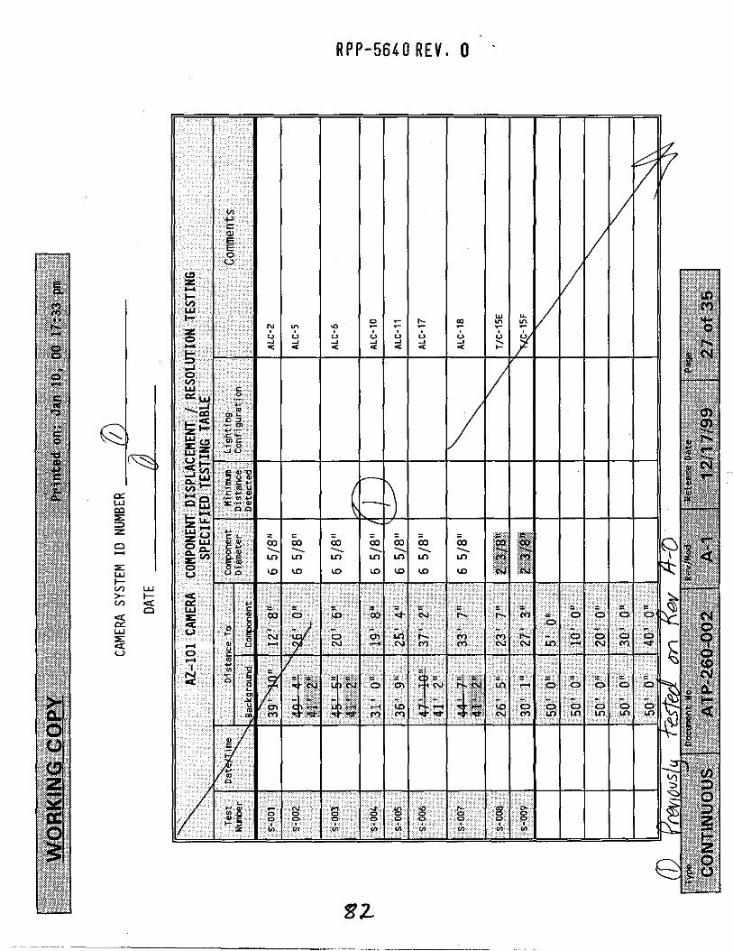
SPECIF IED TESTING TABLE . . . . . . . . . . . . . . . . . . . . . . . . . 2 3
DISCRETIONARY TESTING TABLE . . . . . . . . . . . . . . . . . . . . . . . 2 4
F I G U R E 1 . . . . . . . . . . . . . . . . . . . . . . . . . . . . . . . . 2 5
F I G U R E 2 . . . . . . . . . . . . . . . . . . . . . . . . . . . . . . . . 2 6
ATP PERFORMANCE LOG . . . . . . . . . . . . . . . . . . . . . . . . . . . 2 7
ATP EXCEPTION LOG . . . . . . . . . . . . . . . . . . . . . . . . . . . . 2 8
ATP EXCEPTION RECORD . . . . . . . . . . . . . . . . . . . . . . . . . . 29
PROCEDURE SIGNATURE SHEET . . . . . . . . . . . . . . . . . . . . . . . . 30
PROCEDURE HISTORY SIGNATURE SHEET . . . . . . . . . . . . . . . . . . . . 3 1

WORKING COPY ~ p p - 5 6 4 0 R E V , 0 Printed on: Dec 9, 99 20:05 p
/ / /q/za90 PER AT IONS E N G I N E E ~ SIGNATUREIDATE:
TEST EXECUTION SHEET
/ - I t < O b
RECORDER SIGNATURE / D k ?
DOCUMENT NUMBER: ATP-260-002
I
DOCUMENT TITLE: 241-AZ WASTE TANK COLOR VIDEO CAMERA SYSTEM SHOP ACCEPTANCE TEST PROCEDURE TEST PERSONNEL (PRINT NAMES)
PERA AT IONS ENGINEER: x/w/ionm-L
TEST DIRECTOR SIGNATUREIDATE: I TEST ENGINEER SIGNATUREIDATE:
I
APPROVAL AND ACCEPTANCE OF TEST RESULTS
WITHOUT EXCEPTION WITH EXCEPTIONS RESOLVED WITH EXCEPTIONS REMAINING ~ ( 4 ~ (4
I P R O J E C T MANAGER S I G N A T U R E / D A T E :
LL (4 TEST DIRECTOR SIGNATUREIDATE:
TEST ENGINEER S l G N A T G E / D A T E : W q U A L I T Y A S S ~ T U R E J D A T E :‘
1 - 17.- G o O P E R A T I O N S ENGINEER S l G N A T U R E / D A T E :
J/&3-. )ES I GN AUTHOR 1 TY s I G N h l i E / D A T E :

Printed on: Dec 9, 99 20:05 pm WORKING COPY RPP-5640 R E V . 0
1 Docmen t N 0 . Rer/HoO
CON TIN UOU S ATP-260-002 A-0
c 1 .o PURPOSE AND SCOPE
Rekease Pale Page
12/08/99 4 of 31 I
1.1 PURPOSE
T h i s p rocedure p r o v i d e s i n s t r u c t i o n s t o pe r fo rm ing a Shop Acceptance Tes t Procedure f o r t h e 101 A2 camera system and camera purge gas ( a i r ) system.
1 . 2 SCOPE
T h i s p rocedure s h a l l demonstrate and document acceptance o f t h e 241- AZ-101 Waste Tank C o l o r Video Camera System, camera purge gas ( a i r ) system, and p r o v i d e s v e r i f i c a t i o n t h e y f u n c t i o n as des igned.
The purge system f u n c t i o n s w i l l be t e s t e d v e r i f y i n g p ressu re and f l o w e x i s t s d u r i n g camera system opera t i on .
The purge c o n t r o l system f u n c t i o n s w i l l a l s o be t e s t e d v e r i f y i n g au tomat i c shutdown o f i n t a n k assembl ies and e l e c t r i c a l components i s achieved upon l o s s o f p ressure . F u n c t i o n a l i t y o f d i f f e r e n t i a l p ressu re sw i t ches f o r o p e r a b i l i t y and redundancy t o show no s i n g l e p o i n t f a i l u r e e x i s t s i n e l e c t r i c a l shutdown system.
2.0 INFO RMATlO N
2.1 TERMS AND DEFINITIONS
2.1.1 ALARA - - As Cow A s Reasonably Ach ievab le
2.2 RESPONSIBILITIES
2 . 2 . 1 Tes t Engineer i s r e s p o n s i b l e f o r t h e f o l l o w i n g :
A l l p r e p a r a t i o n s f o r t h i s Tes t have been completed
Suppor t Tes t D i r e c t o r and Tes t Personnel w i t h t h e t e c h n i c a l i n f o r m a t i o n and suppor t necessary t o complete t h i s procedure
2 .2 .2 Opera t i on Personnel a re r e s p o n s i b l e f o r o p e r a t i n g t h e camera systems p e r t h e Tes t Engineer and Tes t d i r e c t o r s d i r e c t i o n .

WORKING COPY Rpp-5640 R E V , 0 Printed on: Dec 9, 99 20:05 pw
1 w e Docmcnt ho.
CONTINUOUS ATP-260-002
2.2 RESPONSIBILITIES (cont.)
2.2.3 Tes t D i r e c t o r i s r e s p o n s i b l e f o r t h e f o l l o w i n g :
RevIMad Release Dale Pa¶@
A-0 12/08/99 5 of 31
O b t a i n i n g r e q u i r e d s i g n a t u r e s on t h e Tes t Procedure Working Copy p r i o r t o r e p r o d u c t i o n and d i s t r i b u t i o n
The sa fe , e f f i c i e n t , and p r o d u c t i v e per formance o f t h e t e s t
C o o r d i n a t i o n o f a l l t e s t i n g a c t i v i t i e s
S i g n i n g t h e Acceptance Tes t Procedure Excep t ion Record when a t e s t excep t ion has been r e s o l v e d
Prepar ing and i s s u i n g an Acceptance Tes t Repor t f o r t h e approved, accepted and completed T e s t Procedure
Schedul ing and conduct ing a p r e - t e s t meet ing w i t h t e s t p a r t i c i p a n t s
N o t i f i c a t i o n o f t h e persons pe r fo rm ing and w i t n e s s i n g t h e t e s t p r i o r t o t h e s t a r t o f t e s t i n g
N o t i f i c a t i o n o f a l l i n v o l v e d t e s t personnel when a change i s made i n t h e t e s t i n g schedule
Ac t as l i a i s o n between t h e p a r t i c i p a n t s i n v o l v e d w i t h t h e t e s t i n g
Stopp ing any t e s t o r s e c t i o n which may cause damage t o t h e system
Approv ing f i e l d changes t o t h e Tes t Procedure i n accordance w i t h S e c t i o n 2.5.3
O b t a i n i n g r e v i s i o n s t o t h e Tes t Procedure, t o comply w i t h a u t h o r i z e d f i e l d changes o r t o accommodate e x i s t i n g f i e l d c o n d i t i o n s i n accordance w i t h S e c t i o n 2.5.3
Tak ing a c t i o n s t o r e s o l v e excep t ions t o t h e T e s t Procedure
E v a l u a t i n g recorded da ta , d i sc repanc ies , and excep t ions
S i g n i n g Tes t Execut ion Sheet when t h i s T e s t Procedure has been per formed
S i g n i n g Except ion Record when a r e t e s t t o c l e a r an excep t ion has been executed and accepted

WORKING COPY ~ p p - 5 6 4 0 REV. 0 Printed on: Dec 9, 99 20:m pm
T Y P "
CONTINUOUS
2.2 RESPONSIBILITIES (cont.)
D0CUnE"t L3 . RevIMod Re.ease Date Page
ATP-260-00 2 A-0 12/08/99 6 of 31
2.2.4 QC Inspector is responsible for witnessing test execution and signing the completed sections of the test.
The Authorized Inspector is responsible for the foll owing:
Witnessing test execution
Approval and signature of acceptance upon completion
2.2.5
2.3.1 Acceptance Test Report 241-AZ-101 Waste Tank Color Video Camera System WHC-SD-WM-ATR-181 Rev 0
2.3.2 Purchase Specification WHC-S-0410, Rev 2 (P.O.# W-408171), "241-AZ-101, W151 Project, Suspended Fixture and Weld Inspection Camera System."
2.3.3 WHC-SD-W151-ETP-001, Rev. 1, "Engineering Task Plan for The 241-AZ-101 Waste Tank Color Video Camera System".
2.3.4 WHC-SD-WM-ATP-181, Rev. 0, "Acceptance Test Procedure 241-AZ-101 Waste Tank Color Video Camera System".
2.4 RECORDS
2.4.1 All personnel involved in the performance of this test shall sign in Procedure Signature Sheet.
2.4.2 Test results shall be recorded by the Test Engineer. All entries into this test procedure shall be made in black ink. Unless specific data is required, the signature o r initials as applicable, of the person accepting the item will be entered in the blank provided to indicate compliance with the stated requirements or the successful completion of the given test step. Errors shall be corrected by crossing out the incorrect data with a single line and the correct response shall be written in the direct vicinity of the original item. The person making the correction shall initial and date the correction. Unacceptable conditions or readings shall be resolved in accordance with Section 2.5 EXCEPTIONS. working copy of this procedure and any exception records generated shall be maintained as a permanent record.
A complete
WORKING COPY RPP-5640 REV. 0 Printed on: Dec 9, 99 20:05 pm
Type Dacment bo. RevJHod R E L ~ Q S C Date
CONTINUOUS ATP-260-002 A-0 12/08/99
2.4 RECORDS (Cont). .-
Page
7 of 31
2.4.3 An Except ion Log and Except ion Record sheet i s a t tached i n t h e event excep t ions t o t h e t e s t a re made when t h e t e s t i s be ing per formed. A l l excep t ions t o t h e t e s t a r e t o be d i s p o s i t i o n e d and agreed t o by a l l w i tnesses . A c t i o n s taken r e g a r d i n g d i s p o s i t i o n a re no ted on t h e e x c e p t i o n sheet . Dur ing t h e performance o f t h i s t e s t , e r r o r s i n t e s t may be encountered which r e q u i r e c o r r e c t i o n / a d j u s t m e n t t o complete t h e t e s t . c o r r e c t i o n s a re t o be no ted i n t h e ATP and l i s t e d as an excep t ion .
Such
3.0 PRECAUTIONS AND LIMITATIONS
3.1 PERSONNEL SAFETY
3.1.1 I f t h e performance o f t h i s p rocedure i s suspended f o r any reason, ensure t h e equipment i s l e f t i n a s a f e s t a t e .
3.1.2 A l l l o c k o u t s and tagou ts o r ove r - tagg ing requ i remen ts s h a l l be per formed i n accordance w i t h Tank Farm A d m i n i s t r a t i o n Manual, HNF-IP-0842, Vol 11, S e c t i o n 4.9.1.
3.1.3 I f any equipment problem i s observed d u r i n g t h e performance o f t h i s procedure, immedia te ly n o t i f y t h e Tes t D i r e c t o r .
p e r t a i n i n g t o t h e compressed a i r system and assoc ia ted hoses, SHALL be inspec ted p r i o r t o v a l v i n g i n t h e a i r .
procedure and personnel s h a l l t a k e p r e c a u t i o n s t o ensure back s t r a i n , p i n c h p o i n t s and p r o t e c t i v e c l o t h i n g a r e observed.
3.1.4 A l l f i t t i n g s and s a f e t y dev ices such as whips and clamps
3.1.5 Proper l i f t i n g techn iques s h a l l be u t i l i z e d th roughou t t h e
Printed on: Dec 9, 99 20:05 pm RPP-5640 RFV. 0 WORKING COPY
type DOCUVEnI LD. RevIHod
CONTINUOUS . ATP-260-002 A-0
6 - 4.0 PREREQUISITES
Re.ea<e DatP Page
12/08/99 8 of 31
4.1 SPECIAL TOOLS, EQUIPMENT, AND SUPPLIES
The f o l l o w i n g s u p p l i e s may be needed t o p e r f o r m t h i s procedure:
4.1.1 Flowmeter (Per Tes t Eng ineer )
4 .1 .2 Stopwatch
4.1.3 CAMERA ASSEMBLY SYSTEM
Camera Mast
Pan And T i l t U n i t
Overview Camera
Two 7 5 w a t t halogen l i g h t s
4 .1 .4 FIELD UNITS
Local I n t e r f a c e U n i t
Hazardous L o c a t i o n C o n t r o l Panel
M o b i l e A i r Compressor A
4.2 SPECIAL TOOLS, EQUIPMENT, AND SUPPLIES (Cont).
4 . 1 . 5 CAMERA CONTROLS
Camera, Pan and T i l t , and L i g h t i n g C o n t r o l s
S Video Co lo r Video M o n i t o r
Keyboard
V C R and v ideo tape
Misc . o p t i o n a l v i d e o measurement and enhancement equipment.
4 .1 .6 TEST FIXTURES
L i f t i n g Adapters / Adapters
S imu la ted I n Tank Comoonents
,-
WORKING COPY ~ p p - 5 6 4 0 REV. 0 P r i n t e d on: Dec 9, 99 20:05 pm
1-e Docment No. Rcv/Mad Release Date
CONTINUOUS ATP-260-002 A-0 12108J99
,
Page
9 of 31
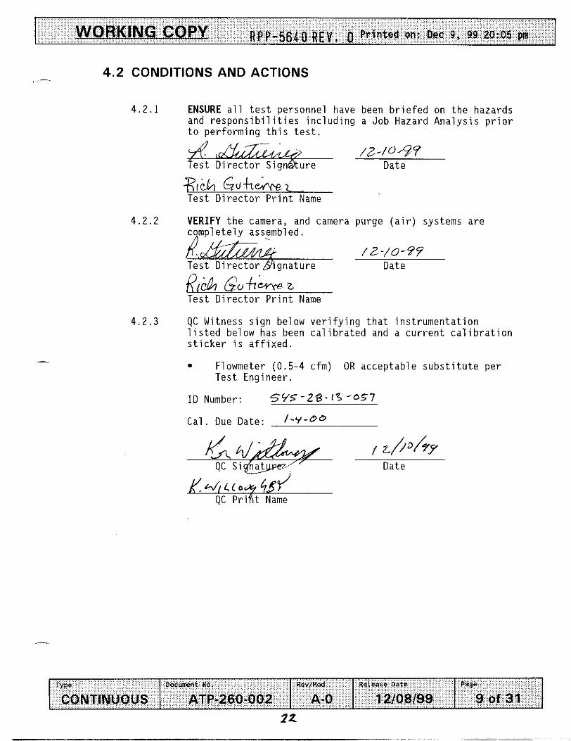
4 .2 CONDITIONS AND ACTIONS
4 . 2 . 1 ENSURE a l l t e s t personne l have been b r i e f e d on t h e hazards and r e s p o n s i b i l i t i e s i n c l u d i n g a Job Hazard A n a l y s i s p r i o r t o p e r f o r m i n g t h i s t e s t .
_. I /Z-/O&? Tes t D i r e c t o r S i g n a t u r e Date
+hbi GukeEN.er Tes t D i r e c t o r P r i n t Name
4.2.2 VERIFY t h e camera, and camera purge ( a i r ) systems a r e c q m p l e t e l y assembled. .
/ 2 - / U - W Date
I,- Tes t D i r e c t o r b i g n a t u r e
Tes t D i r e c t o r P r i n t Name
4.2.3 QC Witness s i g n below v e r i f y i n g t h a t i n s t r u m e n t a t i o n l i s t e d below has been c a l i b r a t e d and a c u r r e n t c a l i b r a t i o n s t i c k e r i s a f f i x e d .
Flowmeter (0.5-4 cfm) OR accep tab le s u b s t i t u t e p e r Tes t Eng ineer .
I D Number: 5 Y 5 - 2 8 - 1 3 *OS7
Cal . Due Date: l-'f-Q*
k / . J , c c o y c i 45 OC Print Name

WORKING COPY ~ p p - 56&n R F V . P r i n t e d on: Oec 9, 99 20:05 pm
Docmmt No. Rev/Mod Re.ease Date TWO
ATP-260-00 2 A-0 12108199 CONTINUOUS
_- 5.0 A , PROCEDURE
Page
10 of 31
- Two c o n t r o l u n i t s need t o be t e s t e d p r i o r t o i n s t a l l a t i o n i n t h e f i e l d . Sect ions 1.0 - 5.5 may be copied, enab l ing t e s t personnel t o per form t e s t i n g o f a d d i t i o n a l c o n t r o l systems. A l l p e r t i n e n t Record Sheets o f t h i s procedure may be copied as w e l l , enab l ing capture o f I D . numbers, t e s t except ion, r e s o l u t i o n and o the r t e s t da ta . A l l s a f e t y p recaut ions and c o n t r o l s w i l l be r e - v e r i f i e d and re-signed f o r each se t o f camera system c o n t r o l s tes ted . Sec t ion 5.6 need on ly be tes ted on one c o n t r o l system.
NOTE - The t o t a l volume f o r t he camera and mast assembly (mast, camera housing, l i g h t housing, pan -and- t i l t , and hoses) i s 1.53 ft3. Per NFPA 496 requirements, t e n volumes o f purge a i r o r 15.3 ft3, must f l o w through t h e system. The Time Delay Relays (TDRs) l oca ted i n t h e Hazardous Locat ion Power C o n t r o l l e r are pre-set t o a minimum of 10.2 minutes a t a minimum f l o w r a t e o f 1 .5 cfm,3(15.3 f t /1.5 cfm = 10.2 minutes) t o a l l o w f o r 15.3 ft t o t a l f l ow . Adjustments t o t ime de lay r e l a y s may be necessary d u r i n g t h e t e s t i n g based on f l o w measurements obta ined. (Ref. s tep 5.2.3)
5.1 START UP AND PURGE SYSTEM TEST
5.1.1 ASSEMBLE Camera system components per t e s t d i r e c t o r s d i r e c t i o n .
TURN ON purge a i r compressor system t o a range o f 15-25 ps ig , a l l ow ing purge a i r t o f l o w through a l l paths.
CHECK each suspect f i t t i n g o r l e a k pa th f o r any s i g n i f i c a n t leakage as determined by Test Engineer, i n purge system, w i t h "SNOOP" o r o the r approved method as d i r e c t e d by Test D i r e c t o r .
5.1.4 REPAIR OR F I X any leaks as necessary
5.1.2
5.1.3
, -_

WORKING CO PY ~ p p - 5640 R E V , 0 Printed on: Dec 9, 99 20:05 pm
Docmen1 bo. ReviMad Re.ease Date IW@
CONTINUOUS ATP-260-002 A-0 12/08/99
5.1 START UP AND PURGE SYSTEM TEST (Cont). ......
Page
11 of 31
5.1 .5
5 .1 .6
5 . 1 . 7
5 . 1 . 8
5 .1 .9
5.1.10
5.1.11
5.1.12
5 .1 .13
VERIFY n Purge path is acceptable for testing , ,'a -m- 9 9
fest Director Sid6ature Date - 7.&u+l&z Test Director Print Name
POSITION the Hazardous Location Power Controller unit to the "ON" position AND
Begin TIMING purge system cycle.
ENSURE the POWER indicating lamp is illuminated.
ENSURE purge supply is allowing flow through Hazardous Location Power Controller.
ENSURE the FLOW indicating lamp is illuminated.
ENSURE the PRESSURE 1 indicating lamp is illuminated.
ENSURE the PRESSURE 2 indicating lamp is illuminated.
AFTER Purge cycle completes, ENSURE ENERGIZED indicator is illuminated AND
STOP timing purge system cycle.
RECORD cycle time below.
11 miu+-c.T 6?6
- WORKING COPY ~ p p - 5 6 4 0 R E V , 0 Printed on: Dec 9, 99 20:05 pm
Type D o c m n t No. Rev/Had Releaae Date
CONTINUOUS ATP-260-002 A-0 12/08/99
._ 5.1 START UP AND PURGE SYSTEM TEST (Cont). ~ O r n ~ ~ O t l I
5 . 1 ' 14 . d N K t h e purge supp ly hose t o t h e camera c u t t i n g o f f f l o w .
VERIFY t h a t system power down occurs a f t e r purge f l o w i s i n t e r r u p t e d , and ENERGIZED, PRESSURE 1 and PRESSURE 2 i n d i c a t o r l i g h t s l o c a t e d on t h e Hazardous L o c a t i o n Power C g t r o l l e r a r e no l o n g e r i l l u m i n a t e d .
5.1.15
Page
1 2 of 31
/d - /a ? ? Date
,&? Gof-leY\rezi Tes t D i r e c t o r P r i n t . Name
5.1.16 VERIFY s e c t i o n 5 . 1 i s complete.
g . & d /2-1+9 9 Tes t D i r e c t o r b j q n a t u r e Date
_-
- _ - R - 6;Utrm Tes t D i r e c t o r P r i n t Name
/ ./.0/77-/ ' qc S i g n a t u r e Date
8
.-

WORKING COPY 5640 B F V , 0 P r i n t e d on: Dec 9, 99 20:05 pm
5.2 PURGE CONTROL SYSTEM AND DIFFERENTIAL PRESSURE SWITCH TEST
,-
5 . 2 . 1
5.2.2
5.2.5
5 . 2 . 1
5.2.8
5.2.9
PLACE a f lowmeter (0 .5 - 4 .0 cfm range o r accep tab le e q u i v a l e n t ) i n - l i n e w i t h t h e purge a i r o u t p u t s i d e o f t h e p ressu re r e l i e f va l ve , l o c a t e d on camera assembly l i g h t hous ing .
ENSURE t o g g l e sw i t ches on t h e d i f f e r e n t i a l p r e s s u r e s w i t c h t e s t box a r e i n t h e ENABLE p o s i t i o n .
fZ?ASd,re J 3 M F d i f f e r e n t i a l p ressu re s w i t c h t e s t box i n l i n e w i t h connec to r 54 (Ref F i g . 2) l o c a t e d on t h e r e a r o f t h e Hazardous L o c a t i o n Power C o n t r o l l e r and connec to r l o c a t e d on t h e bot tom o f t h e l o c a l i n t e r f a c e u n i t . TY EnSue I 5 oil WR" t h e purge a i r supplydAND
PRESS t h e START/RESET b u t t o n l o c a t e d on t h e Hazardous L o c a t i o n Power C o n t r o l l e r .
RECORD t h e f l o w r a t e taken f rom t h e f l owmete r .
Flow Rate /, 2 5 cfm
VERIFY f l o w r a t e i s 1 .5 cfm o r q r e a t e r " ?
A . &A%?&. /Z-/fi-?Y Tes t D i r e c t o r %nature Date -
G , , f 9 r w I Test D i r e c t o r P & Name
TURN OFF purge a i r supp ly
REMOVE f lowmeter f rom system.
TURN ON purge a i r supp ly AND
PRESS t h e START/RESET b u t t o n l o c a t e d on t h e Hazardous L o c a t i o n Power C o n t r o l l e r .
WORKING COPY ~ p p - 5 6 4 0 R E V , 0 P r i n t e d on: Dec 9 , 99 20:05 pin
TYPe Docunent NO. RevIHod Release Oat0
CONTINUOUS ATP-260-002 A-0 12/08/99
5 .2 PURGE CONTROL SYSTEM AND DIFFERENTIAL PRESSURE SWITCH TEST (Cont). c
Pago
14 of 31
i l l u m i n a t e d .
1, PRESSURE 2, and FLOW i n d i c a t o r s a re i l l u m i n a t e d .
5 .2.12 POSIT ION PRESSURE 1 l o c a t e d on t h e t e s t s w i t c h box, t o t h e /
DISABLE p o s i t i o n AND
VERIFY camera c o n t r o l and l i g h t i n g system power i s d i sab l ed . 4&, /a-c.- ?I Tes t D i r e c t o Q S igna tu re Date
' cT"A~e.r,lt L e s t D i r e c t o r P r i n t Name
.I 5.2.13
J'5.2.14
POSITION PRESSURE 1 t o t h e "ENABLE" p o s i t i o n .
PRESS t h e "START/RESET" b u t t o n AND
ENSURE PURGING i n d i c a t o r i s i l l u m i n a t e d .
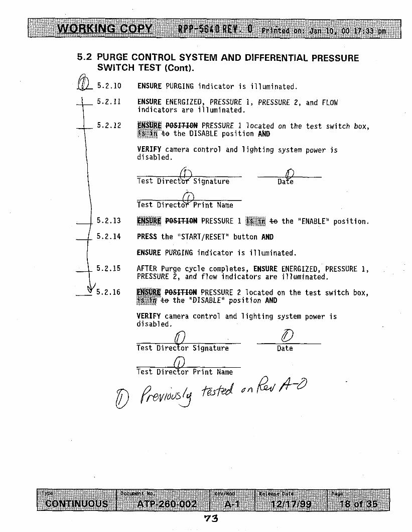
5.2.15 AFTER Purge c y c l e completes, ENSURE ENERGIZED, PRESSURE 1, PRESSURE 2, and f l o w i n d i c a t o r s a re i l l u m i n a t e d .
5 .2.16 POSITION PRESSURE 2 l o c a t e d on t h e t e s t s w i t c h box, t o t h e "DISABLE" p o s i t i o n AND
VERIFY camera c o n t r o l and l i g h t i n g system power i s d i s a b l e d .
/J -/o -9 P Date
R L A k , Tes t D i r e c t o r Prm Name
-.
I7

I WORKING COPY RPP-5640 R E V . 0 Printed on: Dec 9, 99 20:05 pln I 5.2 PURGE CONTROL SYSTEM AND DIFFERENTIAL PRESSURE
SWITCH TEST (Cont).
5.2.17
5.2.18
5.2.19
5.2.20
ATTEMPT t o r e e n e r g i z e system w i t h PRESSURE 2 i n t h e "DISABLED" p o s i t i o n .
VERIFY Hazardous L o c a t i o n Power C o n t r o l l e r w i l l NOT a l l o w camera c o n t r o l and l i g h t i n g system t o ene rg i ze .
/J-/O-- 94 t e ' s t D i r e c t o r S d a t u r e Date
Tes t ' D r r e c t o r P r i n t Name
POSIT ION PRESSURE 2 t o t h e "ENABLE" p o s i t i o n .
POSIT ION PRESSURE 1 t o t h e "DISABLE" p o s i t i o n AND
VERIFY camera c o n t r o l and l i g h t i n g system power i s d i s a b l e d .
/2- 0 -9 'i Date
R &hCrnL Tes t D i r e c t o r P r i n t Name
28

R P P -5640 R E V . 0 P r i n t e d on: Dec 9, 99 20:05 pin WORKING COPY
T w D 0 C U M " t NO. Rev/Mod Release Onto
CONTINUOUS ATP-260-002 A-0 12/08/99
5.2 PURGE CONTROL SYSTEM AND DIFFERENTIAL PRESSURE SWITCH TEST (Cont).
Page
16 of 31
5 . 2 . 2 1 ATTEMPT t o r e e n e r g i z e system w i t h PRESSURE 1 i n t h e
5 . 2 . 2 2 VERIFY Hazardous L o c a t i o n Power C o n t r o l l e r w i l l NOT a l l o w
"DISABLED" p o s i t i o n .
cayera system t o ene rg i ze . \
/ Z - / H 7 Tes t D i r e c t o r S i q t h t u r e Date -
GuhWPez- e s t D i r e c t o r P r i n t Name
5 . 2 . 2 3 REMOVE Test Swi tch Box f rom system AND
RECONNECT 54 Cables.
5 .2 .24 VERIFY S e c t i o n 5 . 2 i s complete
/z -/or 97 Date
~.Gufi;.-rrpz Tes t D i r e c t o r P r i n t Name
c. w l L ( e u , 4 6 - f / QC P r i n t Name

WORKING COPY RPP-5640 R E V . 0 P r i n t e d on: D e c 9, 99 20:05 pm
TYPE Docment ho. Rev/Mod Re.ease Oars
CONTINUOUS ATP-260-002 A-0 12/08/99
RCS-551 CAMERA UNIT
Page
17 of 31
5 . 3 . 1 RECORD s e r i a l number o f camera c o n t r o l u n i t .
NOTE - D u r i n g t h i s p o r t i o n o f t h e t e s t t h e T e s t Engineer s h a l l v e r i f y each camera c o n t r o l i s s a t i s f a c t o r y and w i l l t h e n i n i t i a l t h e space p r o v i d e d f o r each s t e p .
PLUG t h e v i d e o m o n i t o r and v i d e o r e c o r d e r i n t o t h e power source.
VERIFY t h e v i d e o m o n i t o r and v i d e o r e c o r d e r a r e o p e r a t i o n a l .
Us ing remote camera zoom c o n t r o l , man ipu la te t h e zoom c o n t r o l t o wide ang le .
VERIFY t h e zoom moves towards wide when opera ted towards "w ide" .
MANIPULATE t h e zoom c o n t r o l t o t e l e p h o t o .
VERIFY t h e zoom moves towards t e l e p h o t o when opera ted
MANIPULATE t h e i r i s c o n t r o l t o f u l l y open.
/& 5.3 .2
3 c 5.3 .3
$?p& 5.3.4
F 2 5 . 3 . 5
=$-k 5.3.6
5 d 5 . 3 . 7 -_ towards " t e l e p h o t o " .
3L a 5 .3 .8
d 5 . 3 . 9 VERIFY t h e i r i s moves towards open when opera ted towards open.
5&5.3.10
5 2 B . 3 . 1 1
$'5.3.12
5@ 5.3 .13
MANIPULATE t h e i r i s c o n t r o l t o t h e f u l l y c l o s e d p o s i t i o n .
VERIFY t h e i r i s moves towards t h e c l o s e d p o s i t i o n when opera ted t o t h e c l o s e d p o s i t i o n .
Using t h e near focus c o n t r o l , VERIFY t h a t t h e focus a d j u s t s t o near when focused on an o b j e c t t h a t i s " n e a r " .
Us ing t h e f a r focus c o n t r o l , a d j u s t s t o f a r when focused on an o b j e c t t h a t i s " f a r "
VERIFY t h a t t h e focus

WORKING COPY RPP-5641) REV. 0 Printed on: Dec 9, 99 20:05 pm
DocUnent ho. Rev/Md Release Date T YW
CONTINUOUS ATP-260-002 A-0 12/08/99
- 5.3 RCS-551 CAMERA UNIT (Cont).
Page
18 of 31
m . 3 . 1 4
9- M P 5 . 3 . 1 5
j f i s 5 . 3 .16
&@. 3.17
5.3.18
.-
START Video Tape Recording.
Whi le t h e camera i s focused on an o b j e c t , VERIFY t h a t t h e p i c t u r e i s f r e e o f image d e f e c t s such as ghost images, p i c t u r e l a g , d i s t o r t i o n , hum, or smearing.
PLAY BACK t h e p r e v i o u s l y reco rded t a p i n g o f t h e r e s o l u t i o n t e s t .
VERIFY t h a t t h e v i d e o r e c o r d e r operates p r o p e r l y and t h a t t h e image i s accep tab le .
VERIFY S e c t i o n 5.3 i s complete.
Tes t D i r e c t o r S i & t u r e Date
Tes t D i r e c t o r P r i n t Name
I z-/u-:! 4
Q, GhGrc2 r r - I O - 9 9
Date
31
WORKING COPY RPP-5640 R E V . 0 Printed on: Dec 9, 99 20:05 pm
w e DocUMnt No. Rav/Hod RC,ED*e Date
CONTINUOUS ATP-260-002 A-0 12108199
-- 5.4 RCS-551 PAN AND TILT
Page
1 9 of 31
NOTE -
5 .4 .1
d ~ s 5 . 4 . 2
IEQ. 4.3
52%. 4 .4
d . 4 . 5
1 . .+& 5.4.9
D u r i n g t h i s p o r t i o n o f t h e t e s t t h e T e s t Engineer s h a l l VERIFY each pan and t i l t c o n t r o l i s s a t i s f a c t o r y and w i l l t h e n i n i t i a l i n t h e space p r o v i d e d f o r each s t e p .
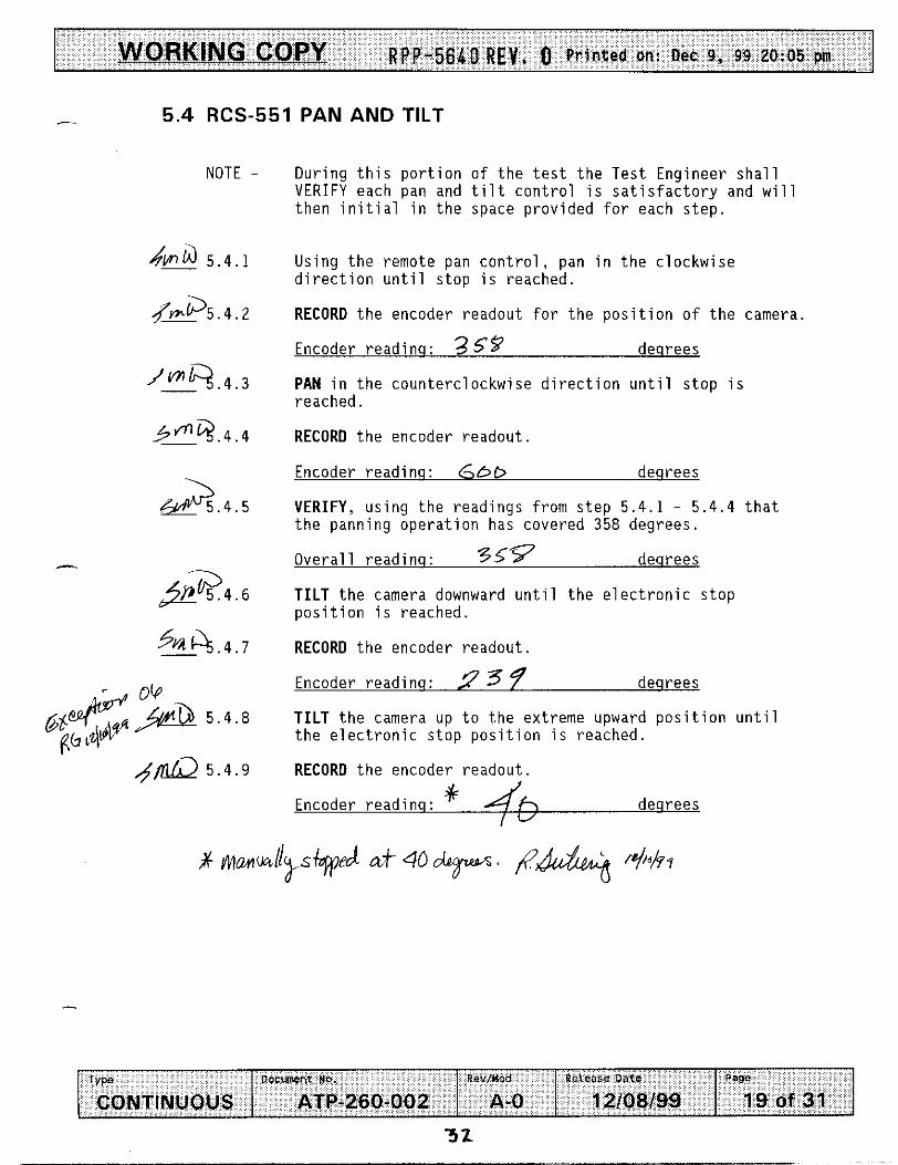
Using t h e remote pan c o n t r o l , pan i n t h e c l o c k w i s e d i r e c t i o n u n t i l s t o p i s reached.
RECORD t h e encoder readou t for t h e p o s i t i o n o f t h e camera.
Encoder r e a d i n q : 3 59 deqrees
PAN i n t h e coun te rc lockw ise d i r e c t i o n u n t i l s t o p i s reached.
RECORD t h e encoder readou t .
Encoder read inq : 6 bb deqrees
VERIFY, u s i n g t h e read ings f rom s t e p 5 .4 .1 - 5.4.4 t h a t t h e panning o p e r a t i o n has covered 358 degrees.
O v e r a l l r ead inq : 3.59 deqrees
TILT t h e camera downward u n t i l t h e e l e c t r o n i c s t o p p o s i t i o n i s reached.
RECORD t h e encoder readou t .
Encoder read inq : 9 37 deqrees
TILT t h e camera up t o t h e extreme upward p o s i t i o n u n t i l t h e e l e c t r o n i c s t o p p o s i t i o n i s reached.
RECORD t h e encoder readou t .
Encoder r e a d i n q : + Jfi deqrees I "

WORKING COPY RPP-5640 R E V . 0 Printed on: Dec 9, 99 20:05 pm
D O C m e n r N 0 . RevfMod Rcieosc Date w e ATP-260-002 A-0 12/08/99 CONTINUOUS
4 5 .4 RCS-551 PAN AND TILT (Cont). 0
- - _
Page
20 of 31
>LA. 4.13
VERIFY u s i n g t h e encoder read ings f rom s teps 5.4.6 - 5.4.9 t h a t t h e t i l t has a range o f 200 degrees min.
O v e r a l l r ead inq : / 4 4 deqrees
DE-ENERGIZE t h e pan and t i l t u n i t .
V E R I F Y t h a t t h e pan and t i l t m a i n t a i n s i t ' s p o s i t i o n .
VERIFY S e c t i o n 5.4 i s complete.
-?? Date
f..h2-. Tes t D i r e c t o r P r i n t Name

WORKING CO PY RPP-5640 REV. 0 Printed on: Dec 9, 99 20:05 pm
DOcUnent No. Rev/Hod TYPO
CONTINUOUS ATP-260-002 A-0
- 5.5 DETECTION OF MOVEMENT TEST
RE.CJSE Date Page
12/08/99 21 of 31
NOTE -
5 . 5 . 2
5 . 5 . 5
Two types o f t e s t s w i l l be per formed and d a t a s h a l l be recorded on e i t h e r t h e S p e c i f i e d T e s t i n g Tab le OR t h e D i s c r e t i o n a r y T e s t i n g Tab le . The o b j e c t i v e i n t h i s t e s t s e c t i o n i s t o de termine t h e minimum d e t e c t a b l e movement, a t v a r i o u s d i s tances , w i t h t h e camera system. Adjustments such as l i g h t i n g changes, camera ad jus tments e t c . may be done a t anyt ime d u r i n g t h i s s e c t i o n as d i r e c t e d by T e s t D i r e c t o r .
$&%%the Hazardous L o c a t i o n Power C o n t r o l l e r u n i t t o t h e "ON" p o s i t i o n AND
ENSURE POWER i n d i c a t o r i s i l l u m i n a t e d .
ENSURE purge supp ly i s a l l o w i n g f l o w th rough Hazardous L o c a t i o n Power C o n t r o l l e r .
ENSURE PURGING i n d i c a t o r i s i l l u m i n a t e d
P E N S U R E ENERGIZED i n d i c a t o r i s i l l u m i n a t e d .
RECORD Tes t Date, and Camera system I D . number on a p p l i c a b l e T e s t i n g Tab le .
5 . 5 . 6
4."' a5 req&dl, RECORD d i s t a n c e on a p p l i c a b l e Tes t Table. ai, '
PLACE a s imu la ted d a r k background, carbon s t e e l p l a t e o r o t h e r s i m i l a r background as approved by T e s t d i r e c t o r , a measured d i s t a n c e f rom t h e camera, AND
1 , -
5 . 5 . 7 PLACE a s imu la ted i n - t a n k assembly BETWEEN t h e camera and t h e s imu la ted background AND
03 us 9 & 8 RECORD component s i z e , and d i s t a n c e on a p p l i c a b l e Tes t Tab le .
5 . 5 . 8 ELIMINATE A l l non-camera l i g h t sources as comp le te l y as p o s s i b l e , AND
RECORD any l i g h t sources s t i l l p resen t on t h e Performance Log.
5 . 5 . 9 FOCUS camera on s imu la ted assembly.

WORKING COPY RPP-5640 R E V . 0 P r i n t e d on: Dec 9, 99 20:05 pm
Docmenr N 0 . &,/Moa Relfo6~ Date 1YPe
ATP-260-002 A-0 12l08199 CONTINUOUS
- 5.5 DETECTION OF MOVEMENT TEST (Cont).
Page
22 of 31
5.5.10
5 .5 .11
5.5.12
5 .5 .13
5.5.14
,-
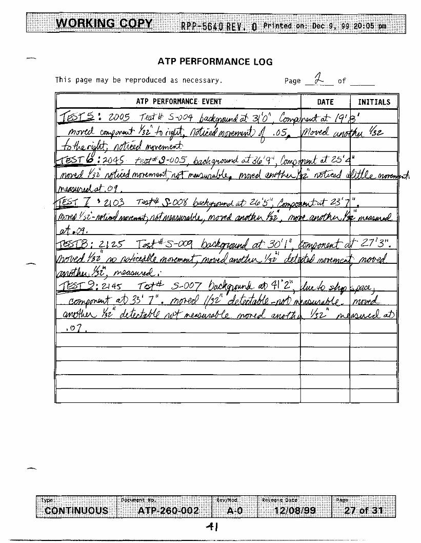
MOVE simulated assembly in 1/32" increments, until camera operator detects movement.
RECORD the distance moved on applicable Test Table.
RECORD any special camera adjustments, lighting changes, or any comments on applicable Test Table.
REPEAT steps 5.5.7 - 5.5.12 as directed by Test Director to determine minimum movement detectable.
VERIFY Section 5.5 is complete.
/z -10 -97 Test Director Si&ature Date
G u h m w Test Director Print Name
I.(.I1I,LI+lq J QC Print' Name

W I- s
RPP-5640 R E V . 0
--h

RPP-5640 R E V . 0

WORKING COPY RPP-5640 R E V , 0 Printed on: Dec 9, 99 20:05 pm I
TYPO
CONTINUOUS
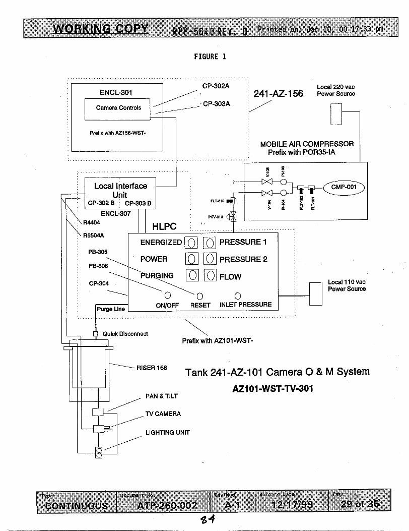
FIGURE 1
Docunmt No. Rev/Mod Roleme Date PaQe
ATP-260-002 A-0 12/08/99 25 of 31
CP-302% Local 220 vac 241 -AZ-l56 Power Source ,
, CP-303A ,
1\ ,*\RM04 I I
1 I HLPC ._ IL-- .~~ ~ 1 R6504A
~ ENERGIZED I PB-305 I IOWER PE-306
MOBILE AIR COMPRESSOR Prefix with POR35-IA
F I R E S S U R E 2 1 r ~~~ i
Local 11 0 vac Power Source
-..I 'PURGING 1 (1~) 1 1 (.I 1 FLOW
,, [~'j ' L ~ l
... .. . .. -. .. .. CP-304
,~ ,,
ON/OFF RESET INLET PRESSURE .~ . -.
\
'\,~
I Quick Disconnect
Prefix with AZ101-WST-
Tank 241 -AZ-101 Camera 0 & M System ~ ~ ~ - .
A21 01 -WST-TV-301
38
WORKING COPY RPP-5640 R E V . 0 Printed on: Dec 9, 99 20:05 pm
DOCUnent hO.
CONTINUOUS ATP-260-002
.-
Rev/Mod ~7e.fas.e Date Page
26 of 31 A-0 12/08/99
A
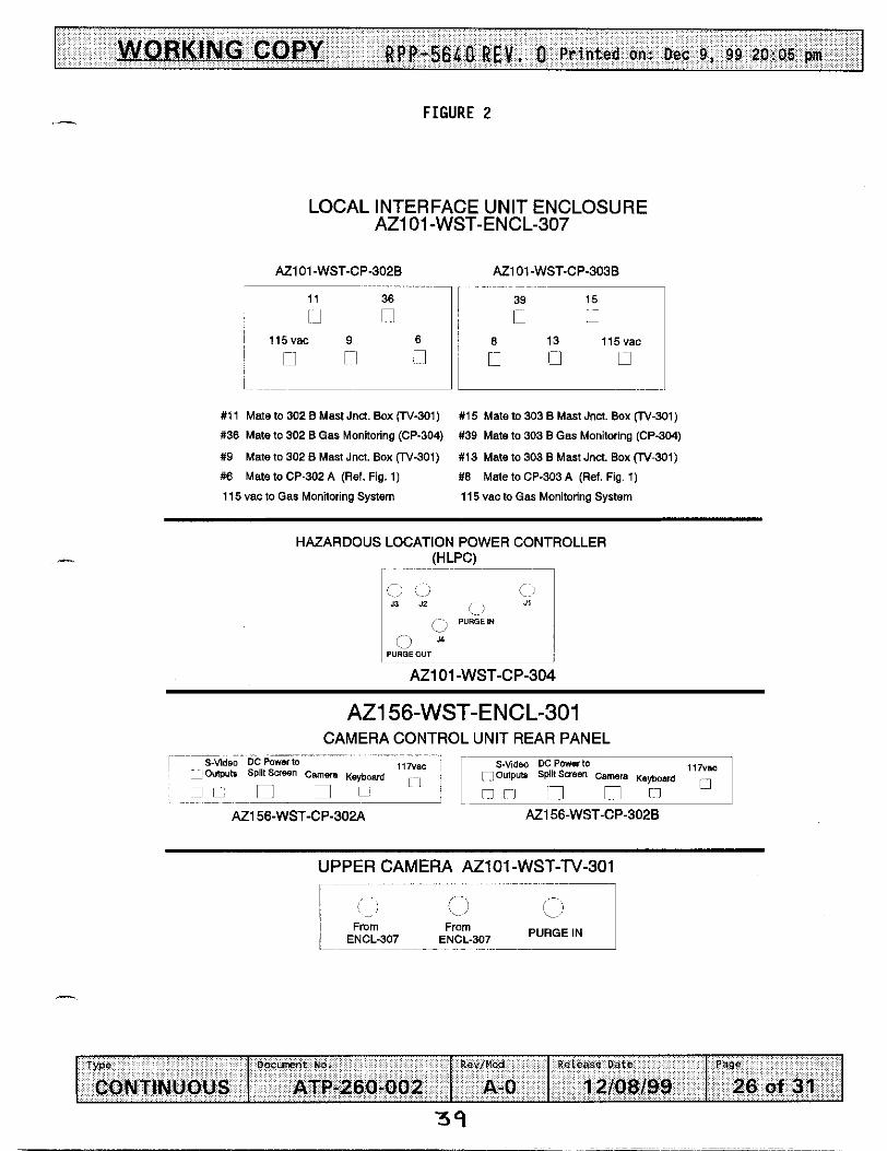
FIGURE 2
LOCAL INTERFACE UNIT ENCLOSURE A21 01-WST-ENCL-307
A21 01 -WST-CP-302B AZlOl-WST-CP-303B
11 36
11 n 115vac 9 6
1- 1 r-l 1
39 15
u L7
n u 0 8 13 115vac
#11 Mate to 302 B Mast Jnct. Box (Tv-301)
#36 Mate to 302 B Gas Monitoring (CP-304)
#9 Male to 302 B Mast Jnct. Box (Tv-301)
#6 Mate to CP-302 A (Ref. Fig. 1)
11 5 vac to Gas Monitoring System
#15 Mate to 303 B Mast Jncl. Box (TV-301)
#39 Mate 10 303 B Gas Monitoring (CP-304)
# I3 Mate to 303 B Mast Jnct. Box CTv-301)
#E Male to CP-303 A (Ref. Fig. 1)
11 5 vac to Gas Monitoring System
HAZARDOUS LOCATION POWER CONTROLLER (HLPC)
~ ~ ~ ~ ~ ~ ~ ~ ~ ~ _ _ _ _ _ _ ~
:);.. (..I PURGEIN ( ~ ~ j i ; ]
PUROEOUT
AZ101-WST-CP-304
PURGEIN ~
I From From ENCL-307 ENCL-307 i- ~~~ .. .-
RPP-5640 R E V . 0 ATP PERFORMANCE LOG
T h i s page may be reproduced as necessary. Page f o f ~
TVpe O o c u M n t no. Rev/Mod Retease Dare
CONTINUOUS ATP-260-002 A-0 12/08/99
J
Pew
27 of 31
4 0
WORKING COPY RPp-56&0 REV, 0 Printed on: Dec 9, 99 20:05 pm
Type Docmsnt No.
CONTINUOUS ATP-260-002
ATP PERFORMANCE LOG
T h i s page may be reproduced as necessary. Page & of __
I
RevJHod PeceaZe Date Pago
A-0 12/08/99 27 of 31

WORKING COPY RPP-5640 REV. O P r i n t e d on: Dec 9, 99 20:05 pm
Type D o c e n t ha. Revmad Release Oate
CONTINUOUS ATP-260-002 A-0 12/08/99
I ATP EXCEPTION LOG
T h i s page may be reproduced as necessary. Page I o f -
Page
20 of 31
--
e
0 3
WORKING COPY RPP-5640 REV, 0 Printed on: Dec 9, 99 20:05 pm
TEST DIRECTOR SIGNATURE:
74 &*
ATP EXCEPTION RECORD
DATE : / Z-/’Y-?9
- T h i s page may be reproduced as necessary.
o f
Type Docment ho. Rcv/Hod Release Oaf=
CONTINUOUS ATP-260-002 A-0 12/08/99
ATP EXCEPTION LOG#: OL - 6 - = - 3 - & 6 -
ATP STEP NUMBER:
DESCRIPTION OF EXCEPTION:
- 7-225-7- rnFUtWvl M m Ai75 Lj4wzkm ‘ s (57iw-u A - . O h & J I 6 f l O f @ / </d .
/
Page
29 of 31
DATE OF EXCEPTION: (z-/o-v A L 7
RESOLUTION O F EXCEPTION:
DATE OF RESOLUTION:
1 DATE : u TEST E N G ~ E R IFNA NATURE : / 2 - , e 97
QUALITY ASSURANCE SIGNA TU^ 1 DATE :

I WORKING COPY RPfJ-5640 REV, 0 Printed on: Dec 9, 99 20:05 pm
Q U A L I T Y ASSURANCE SIGNATU-
ATP EXCEPTION RECORD
DATE : / . 4 - - 7 ?
(2'15-95 DATE :
DATE :
T h i s page may be reproduced as necessary. Page o f
type Docunmt No.
CONTINUOUS ATP-260-002 Rev/Mad Reieane Dare Page
A - 0 12/08/99 29 of 31
44

WORKING COPY RPP-5640 R E V . O Pr in ted on: Dec 9, 99 20:05 pm
q U A L l T Y ASSURANCE SIGNATURE: u
ATP EXCEPTION RECORD
DATE : /z-/5-??
1 2 . / . 5 ' - $ Y
DATE :
DATE : / J - / Y - ? Y
T h i s page may be reproduced as necessary . Page o f __
Type
CONTINUOUS
ATP EXCEPTION LOG#:
0 3 ATP STEP NUMBER:
D o c m n t ha. Rev/Mod Reieare Date Page
ATP-260-002 A-0 12108199 29 of 31
RESOLUTION OF EXCEPTION:
TEST DIRECTOR INITIAL: DATE :
DATE O F RESOLUTION:
45

WORKING COPY RPP-5640 R E V . 0 Printed on: Dec 9, 99 20:05 pm 1
Type D o c m m t ha. Rcv/Mad
CONTINUOUS ATP-260-002 A-0
ATP EXCEPTION RECORD
ReLea,e Dale Page
12/08/99 29 of 31
This page may be reproduced as necessary. Page o f
.-
CORRECT ION APPROVAL :
TEST DIRECTOR INITIAL: DATE :
DATE O F RESOLUTION:

WORKING COPY RPP-5640 R E V * 0 P r i n t e d on: Dec 9 , 99 20:05 pm 1
TYPC D O C U M n t No. Rev/Yod Release Date
CONTINUOUS ATP-260-002 A-0 12/08/99
ATP EXCEPTION RECORD
Page
29 of 31
T h i s p a g e may b e r e p r o d u c e d as n e c e s s a r y . Page o f
Pw k 9 e * 2 e / , a A add & s % ShrS RESOLUTION OF EXCEPTION:
P"f% 4-w SqstOm,. u 4 I V
4 7
WORKING COPY RPP-5640 REV- 0 P r i n t e d on: Dec 9, 99 20:05 pm
TEST E N C ~ E R ,SIGNATURE:
ATP EXCEPTION RECORD
DATE :
/c-\4 fy DATE :
.- T h i s page may be reproduced as necessary. Page
o f
ATP EXCEPTION LOG#: 5-4. ATP STEP NUMBER:
Type D o c w n t ha. Rev/Mod Release Dare
CONTINUOUS ATP-260-002 A-0 12/08/99
R. -&/- OpJ I N I T I ATOR NAME/ORCANlZAT ION :
Page
29 of 31
J ' DATE OF EXCEPTION:
RESOLUTION OF EXCEPTION:
CORRECTION APPROVAL:
TEST DIRECTOR INITIAL: DATE :
DATE OF RESOLUTION:
O U A L I T ~ ASSURANCE SICNATURW I DATE :

WORKING COPY RPP-5640 R E V . 0 Printed on: Dec 9, 99 20:05 pm 1
ATP STEP NUMBER: 4-. 4 10
ATP EXCEPTION RECORD
T h i s page may be reproduced as necessary. Page n f
ATP EXCEPTION LOG#: 07
Type O o c w n t No. Rcvlblad Release DX.Z
CONTINUOUS ATP-260-002 A-0 12/08/99
TEsr DIRECTOR INITIAL: DATE :
Page
29 of 3 1
DATE OF RESOLUTION:

WORKING COPY RPP-5640 R E V , 0 Printed on: Dec 9, 99 20:05 pm 1
I w D o c m n t No. Rev/Mcd R c ~ E ~ s ~ Oate
CONTINUOUS ATP-260-00 2 A-0 12/08/99
ATP EXCEPTION RECORD
T h i s page may be reproduced as necessary. Page o f __
Page
29 of 31
ATP EXCEPTION LOG#: -, ATP STEP NUMBER: of 5.5 .3 DESCRIPTION OF EXCEPTION:
mfi "P/laJJ $A? srnQr/kaw'' @a" l;zm**. f i & d Y 4 .
S I N 1 T I ATOR NAME/ORGANl Z A T l O N : ,
@c / Z - / b - 9 ?
DATE OF EXCEPTION: /Z/, d,/y 9 )I RESOLUTION OF EXCEPTION:
CORRECTION APPROVAL:
TEST DIRECTOR INITIAL: DATE :
DATE OF RESOLUTION:
TEST DIRECTOR SIGNATURE: 1 DATE :

WORKING COPY RPp-5640 R E V , 0 Printed on: Dec 9, 99 20:05 pin
ATP STEP NUMBER. -4=+53--5.5. q
ATP EXCEPTION RECORD
T h i s page may be reproduced as necessary. Page n f
ATP EXCEPTION LOG#:
0"
Q U A L I ~ ASSURANCE SIGNATURE: u w d u
11 DESCRIPTION OF EXCEPTION:
DATE : /z-/s- 77
1-L * I s ' - sq DATE :
DATE : /2 - /4 -$7
. I L
RESOLUTION OF EXCEPTION :
Docunenr no. RevjMcd Reieare Date 1 w CONTINUOUS ATP-260-002 A-0 12l08199
CORRECTION APPROVAL :
TEST DIRECTOR INITIAL: DATE :
DATE OF RESOLUTION:
PaQe
29 of 31

T h i s page may be reproduced as necessary. Page o f __
4TP STEP NUMBER: zfEC4ad mfl f l le 7ZWl.K'
ATP EXCEPTION LOG#: F? / D
)ESCRlPTION OF EXCEPTION:
TEST DIRECTOR INITIAL: DATE:

WORKING COPY RPP-5640 RE V . 0 Printed on: Dec 9, 99 20:05 pm
,- PROCEDURE SIGNATURE SHEET
SIGNATURE I N I T I A L S
Kd
WORKING COPY Rpp-5640 REV. 0 P r i n t e d on: Dec 9, 99 20:05 pm
w e DDCLBnent ND. Revluod Re.ease Date
CONTINUOUS ATP-260-002 A-0 12/08/99
1 PROCEDURE HISTORY SIGNATURE SHEET
Pago
31 of 31
x
5 4
RF'P-5640 REV. 0
'*A
7.0 ATTACHMENT 3 - ATP-260-002 REV. A-Q: TEST PHASE 2
55

241 -A2 WASTE TANK COLOR VIDEO CAMERA SYSTEM SHOP ACCEPTANCE TEST PROCEDURE
Las t F u l l Revis ion: A-0
Release Date: 12/08/99
USQ Screening Number: N/A
Approval Designator: SQ
Current M o d i f i c a t i o n : A-1
USQ Screening Number: TF-98-1201 Rev 1
Approval Designator: Q PCA Incorporated: ETF-99-751
POSITION/ORG DELEGATE DATE
NCO/WTF V i c k i M i l l e r 12/17/99
- SOM R. G u t i e r r e z 1 2 / I 7/99
w!x W.L. Adam 12/17/99
Coq Enq/DST W.M.Hartv Jr. 12/16/99
Acceotance Review David W. VanDvke 12/17/99
Approval A u t h o r i t y Rich G u i t e r r i e z 12/17/99 ~p ~~ ~
J u s t i f i c a t i o n : Ops Request.
Summary o f Changes: In section 2.4 added in General Information. In section 5 . 0 various editorial changes through-out procedure.
Section 5.2 changed FLOW-Rate, Section 5.5 Added ENSURE and deleted part of steps as not neccessary. Specified Table Changed distance requirements.

TABLE OF CONTENTS TEST EXECUTION SHEET . . . . . . . . . . . . . . 1.0 PURPOSE AND SCOPE . . . . . . . . . . . . .
1.1 PURPOSE . . . . . . . . . . . . . . . 1.2 SCOPE . . . . . . . . . . . . . . . . .
2.0 INFORMATION . . . . . . . . . . . . . . . . 2.1 TERMS AND D E F I N I T I O N S . . . . . . . . . 2.2 R E S P O N S I B I L I T I E S . . . . . . . . . . . 2.3 REFERENCES . . . . . . . . . . . . . . 2.4 GENERAL INFORMATION . . . . . . . . . . 2 . 5 RECORDS . . . . . . . . . . . . . . . .
3.0 PRECAUTIONS AND L I M I T A T I O N S . . . . . . . . 3.1 PERSONNEL SAFETY . . . . . . . . . . .
4.0 PREREQUISITES . . . . . . . . . . . . . . 4.1 SPECIAL TOOLS. EQUIPMENT. AND SUPPLIES 4.2 CONDITIONS AND ACTIONS . . . . . . . .
. . . . . . . . . .
. . . . . . . . . . . . . . . . . . . . . . . . . . . . . .
. . . . . . . . . . . . . . . . . . . . . . . . . . . . . . . . . . . . . . . . . . . . . . . . . . . . . . . . . . . .
. . . . . . . . . . . . . . . . . . . . . . . . . . . . . . . . . . . . . . . . .
5.0 PROCEDURE . . . . . . . . . . . . . . . . . . . . . . . . . . 5.2 5.1 START UP AND PURGE SYSTEM TEST . . . . . . . . . . . . . .
5.5 DETECTION OF MOVEMENT EST . . . . . . . . . . . . . . . .
PURGE CONTROL SYSTEM AND DIFFERENTIAL PRESSURE SWITCH TEST 5 . 3 RCS-551 CAMERA U N I T . . . . . . . . . . . . . . . . . . . . 5.4 RCS-551 PAN AND T ILT . . . . . . . . . . . . . . . . . .
PAGE . . 3
. . 4 . . 4 . . 4
. . 4 . . 4 . . 4 . . 6 . . 7 . . 10
. . 11 . . 11
. . 1 2 . . 12 . . 13
. . . . . . . . . . . .
14 14 17 21 2 3 2 5
S P E C I F I E D TESTING TABLE . . . . . . . . . . . . . . . . . . . . . . . . . 27
DISCRETIONARY TESTING TABLE . . . . . . . . . . . . . . . . . . . . . . . . 2 8
F I G U R E 1 . . . . . . . . . . . . . . . . . . . . . . . . . . . . . . . . 29
F I G U R E 2 . . . . . . . . . . . . . . . . . . . . . . . . . . . . . . . . 30
ATP PERFORMANCE LOG . . . . . . . . . . . . . . . . . . . . . . . . . . . 31
ATP EXCEPTION LOG . . . . . . . . . . . . . . . . . . . . . . . . . . . . 3 2
ATP EXCEPTION RECORD . . . . . . . . . . . . . . . . . . . . . . . . . . 33
PROCEDURE SIGNATURE SHEET . . . . . . . . . . . . . . . . . . . . . . . . 34
PROCEDURE HISTORY SIGNATURE SHEET . . . . . . . . . . . . . . . . . . . . 35
57 - . .

- @ppw5G60 R E Y 8 a Printed an: Jan 10, 00 17:33 pm 1 TEST EXECUTION SHEET
OPERATIONS ENGINEER SIGNATUREJDATE:

r WORK ING COPY Rpp-5640 B E V g Printed on: Jan 10, 00 17:33 pm
1 .o PURPOSE AND SCOPE
1.1 PURPOSE
This procedure provides instructions to performing a Shop Acceptance Test Procedure for the 101 AZ camera system and camera purge gas (air) system.
1.2 SCOPE
This procedure shall demonstrate and document acceptance of the 241- AZ-101 Waste Tank Color Video Camera System, camera purge gas (air) system, and provides verification they function as designed.
The purge system flow exists during camera system operation.
The purge control system functions will also be tested verifying automatic shutdown o f in tank assemblies and electrical components is achieved upon loss of pressure. Functionality o f differential pressure switches for operability and redundancy to show no single point failure exists in electrical shutdown system.
functions will be tested verifying pressure and
2.0 INFORMATION
2.1 TERMS AND DEFINITIONS
2.1.1 ALARA - - A s Cow As Reasonably Achievable
2.2 RESPONSIBILITIES
2.2.1 Test Engineer is responsible for the following:
All preparations for this Test have been completed
Support Test Director and Test Personnel with the techn'ical information and support necessary to complete this procedure
2.2.2 Operation Personnel are responsible for operating the camera systems per the Test Engineer and Test directors direction.

I WORKING COP Y RpP-56411 R E V . 0 Printed on: Jan 10, 00 17:33 pm
2.2 RESPONSIBILITIES (cont.)
2.2.3 Test D i r e c t o r i s respons ib le f o r t he f o l l o w i n g :
Obta in ing r e q u i r e d s ignatures on t h e T e s t Procedure Working Copy p r i o r t o rep roduc t i on and d i s t r i b u t i o n
The safe, e f f i c i e n t , and p roduc t i ve performance o f t h e t e s t
Coord inat ion o f a l l t e s t i n g a c t i v i t i e s
Sign ing t h e Acceptance Test Procedure Except ion Record when a t e s t except ion has been reso lved
Prepar ing and i s s u i n g an Acceptance Test Report f o r t h e approved, accepted and completed Test Procedure
Scheduling and conduct ing a p r e - t e s t meet ing w i t h t e s t p a r t i c i p a n t s
N o t i f i c a t i o n o f t h e persons per forming and w i tness ing t h e t e s t p r i o r t o t h e s t a r t o f t e s t i n g
N o t i f i c a t i o n o f a l l i n v o l v e d t e s t personnel when a change i s made i n t h e t e s t i n g schedule
A c t as l i a i s o n between t h e p a r t i c i p a n t s i n v o l v e d w i t h t h e t e s t i n g
Stopping any t e s t o r s e c t i o n which may cause damage t o t h e system
Approving f i e l d changes t o t h e Test Procedure i n accordance w i t h Sect ion 2.5.3
Obta in ing r e v i s i o n s t o t h e Test Procedure, t o comply w i t h author ized f i e l d changes o r t o accommodate e x i s t i n g f i e l d cond i t i ons i n accordance w i t h Sect ion 2.5.3
Taking ac t i ons t o reso lve except ions t o t h e Test Procedure
Evaluat ing recorded data, d iscrepancies, and except ions
Sign ing Test Execution Sheet when t h i s Test Procedure has been performed
Signing Except ion Record when a r e t e s t t o c l e a r an except ion has been executed and accepted

WORKING CO PY gPP-$$d@ffEY. 0 Pritited on: Jan 10, 00 37:33 pm
2.2 RESPONSIBILITIES (cont.)
2.2.4 QC Inspector is responsible for witnessing test execution and signing the completed sections o f the test.
The Authorized Inspector is responsible for the f o l 1 owing:
Witnessing test execution
Approval and signature of acceptance upon completion
2.2.5
of this procedure.
2.3 REFERENCES
2.3.1 Acceptance Test Report 241-AZ-101 Waste Tank Color Video Camera System WHC-SD-WM-ATR-181 Rev 0
Purchase Specification WHC-S-0410, Rev 2 (P.O.# W-408171), "241-AZ-101, W151 Project, Suspended Fixture and Weld Inspection Camera System."
2.3.3 WHC-SO-W151-ETP-001, Rev. 1, "Engineering Task Plan for The 241-AZ-101 Waste Tank Color Video Camera System".
2.3.4 WHC-SD-WM-ATP-181, Rev. 0, "Acceptance Test Procedure 241-AZ-101 Waste Tank Color Video Camera System".
2.3.2
61
I WORKING C OPY RPP-5640 REV. 0 Priiited on: Jan 10, OD 17:33 pin
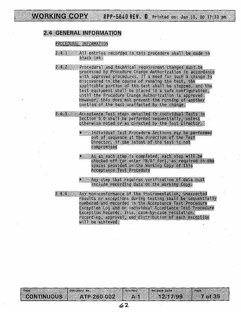
2.A,3 Acceptance lest steps detailed in ind Section 5.0 shall be performed sequen otherwise noted or as directed by the
Individual Te Procedure Sect ions out of sequen a t the direction o Director, I F the Intent of the tes compromised
Any step that requires verification,af data must include recording data on the Working Copy.
2.4.4 Any non-conformance o f the instrumen results o r exceptions during testing numbered and recorded in the Accepta Exception Log and on individual Acce Exception Records. Thus, case-by-cas recording, approval, and distrtbutio will be achieved.
6 2

1 ORKING COPY ff PP-5640 REV. @ Printed on: Jan 10, 00 17:33 pm 1 2.4 GENERAL 1NFORMATION (Cant).
2.4.5 Resolve test exceptions in the following manner:
Hhen the action taken does no acceptable retest, provide a w h y the retest action was not additional plans are required then signs and dates the Resolutlon of the Acceptance Test Prscedu and obtains any other approvals
n of at
ion d,
Acceptance o f Test Resu Sheet.
NOTE - The following steps detail the possible condi may exist at the completton o f the fit, Procedure, and the steps necessary to in those conditions.
63

RPP-5640 R E V . 0 Printed on: Jan 10, 00 17:33 pm
2.4 GENERAL INFORMATION (Cont).
2.4.7 The completed tes t may be approved without test except ions:
Check applicable space on Test Exgcution Sheet t o show t h a t the Acceptance Test Procedure has peen performed and no exceptions have been recorded
Appropriate indiv idua l Test Performers will sign and date the Test Execution Sheet i n the spaces provided
Distribute requisite copies as directed by the client
The completed t e s t may be appro resolved:
pt i ons
Check appl ic xecyt show that t h 0, Peb exceptions record
j Aporoprjate i date the Test
Distribute requi'site cop$es.,as d1,fBcted

i WORK ING CO PY BPp-5640 REV, 0 Printed on: Jan 10, 00 17:33 pm
. .... . . . . . . . ... .. . . . . . . . . . . . .
2.5.3 An .Exception Log and Exception RECO tn iiS the' event exceptloas to the test ar
being performed; , A73 ex~ept?ons to dispositioned and'agreed to by all taken regardir)g dispgsition are~no sheet. During the performance, of t test, may be' epcountqred whlch 'r
i n the procedure and 1 t o complqte the.test 0
65

I WORKING COPY Rpp-5fj4Q R E V , 0 Prilited on: Jan 10, 00 17:33 pm
3.0 PRECAUTIONS AND LIMITATIONS
3.1 PERSONNEL SAFETY
3.1.1 If the performance of this procedure is suspended for any reason, ensure the equipment is left in a safe state.
3.1.2 All lockouts and tagouts or over-tagging requirements shall be performed in accordance with Tank Farm Administration Manual, HNF-IP-0842, Vo l 11, Section 4.9.1.
If any equipment problem is observed during the performance o f this procedure, immediately notify the Test Director.
3.1.3
3.1.4 All fittings and safety devices such as whips and clamps pertaining to the compressed air system and associated hoses, SHALL be inspected prior to valving in the air.
procedure and personnel shall take precautions to ensure back strain, pinchpoints and protective clothing are observed.
3.1.5 Proper lifting techniques shall be utilized throughout the

4.0 PREREQUISITES
4.1 SPECIAL TOOLS, EQUIPMENT, AND SUPPLIES
The following supplies may be needed to perform this procedure:
4.1.1 Flowmeter (Per Test Engineer)
4.1.2 Stopwatch
4.1.3 CAMERA ASSEMBLY SYSTEM
Camera Mast
Pan And Tilt Unit
Overview Camera
Two 75 watt halogen lights
4.1.4 FIELD UNITS
Local Interface Unit
Hazardous Location Control Panel
Mobile Air Compressor
4.1.5 CAMERA CONTROLS
Camera, Pan and Tilt, and Lighting Controls
S Video Color Video Monitor
Keyboard
VCR and videotape
Misc. optional video measurement and enhancement equipment.
4.1.6 TEST FIXTURES
Lifting Adapters / Adapters
Simulated In Tank Components
67

WORKING COPY RPP-5640 REV. 0 Printed on: Jan 10, 00 17:33 pm 1 4.2 CONDITIONS AND ACTIONS
4.2.1 ENSURE all test personnel have been briefed on the hazards and responsibilities including a Job Hazard Analysis prior to performing this test.
Test Director Signature L
Date n 0 0)
Test Director Print Name
4.2.2 VERIFY the camera, and camera purge (air) systems are completely assembled.
L Date
0 Test Director Signature
I Test Dirztor Print Name
4.2.3 QC Witness sign below verifying that instrumentation listed below has been calibrated and a current calibration sticker is affixed.
Flowmeter (0.5-4 cfm) OR acceptable substitute per Test Engineer.
ID Number:
Cal. Due Date:
Date f l
QC Signature -
A OC Priht Name

5.0 PROCEDURE
NOTE - Two control units need to be tested prior to installation in the field. Sections 1.0 - 5.5 may be copied, enabling test personnel to perform testing of additional control systems. All pertinent Record Sheets of this procedure may be copied as well, enabling capture of ID. numbers, test exception, resolution and other test data. All safety precautions and controls will be re-verified and re-signed for each set of camera system controls tested. Section 5.6 need only be tested on one control system.
The total volume for the camera and mast assembly (mast, camera Qousing, light housing, pan-and-tilt, and hoses) is 1.53 ft . Per3NFPA 496 requirements, ten volumes of purge air or 15.3 ft , must flow through the system. The Time Delay Relays (TDRs) located in the Hazardous Location Power Controller are pre-set to a mini migutes w rate of I 4 5 ft3/L§ ~ XkZ minutes) llow for 15.3 ft tota ts to time delay relays may be necessary during the testing based on flow measurements obtained. (Ref. step 5.2.3)
NOTE -
5.1 START UP AND PURGE SYSTEM TEST
ASSEMBLE Camera system components per test directors direction.
@ 5.1.1 I
5.1.2 TURN ON purge air compressor system to a range of 15-25 psig, allowing purge air to flow through all paths.
CHECK each suspect fitting or leak path for any significant leakage as determined by Test Engineer, in purge system, with "SNOOP" or other approved method as directed by Test Director.
REPAIR OR FIX any leaks as necessary
5.1.3
- 5.1.4
v BPf'4564BWEY+ 0 Pri6ted on: Jan 10, 00 17:33 pm
5.1 START UP AND PURGE SYSTEM TEST (Cont).
@ 5.1.5 i
5.1.6 1 5.1.7 i 5.1.8
I
5.1.9 t 5.1.10 I
5.1.11
5.1.12 i- - 5.1.13
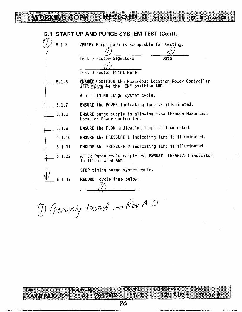
VERIFY Purge I path is acceptable for testing. -
Date 0 I I /
Test Director Print Name ~~~~~
. . f%SF" the Hazardous Location Power Controller .:.:.:.2.+,2:....: ..., .:.:.,:-.:.*.,. :,.,I unit'':~$&~ & the IIONlI position AND
./....,.... ... :::; . . ... .̂ . .
Begin T I M I N G purge system cycle.
ENSURE the POWER indicating lamp is illuminated.
ENSURE purge supply is allowing flow through Hazardous Location Power Controller.
ENSURE the FLOW indicating lamp is illuminated.
ENSURE the PRESSURE 1 indicating lamp is illuminated.
ENSURE the PRESSURE 2 indicating lamp is illuminated.
AFTER Purge cycle completes, ENSURE ENERGIZED indicator is illuminated AND
STOP timing purge system cycle.
RECORD cycle time below. 7%
70

WORK ING COPY RPP-5640 REV. 0 Pr i i ted an: Jan 10, 00 17:33 pm 1 5.1 START UP AND PURGE SYSTEM TEST (Cont).
fl 5.1.14 Manually KINK the purge supply hose to the camera cu
\ 5.1.15 VERIFY that system power down occurs after purge flow is
interrupted, and ENERGIZED, PRESSURE 1 and PRESSURE 2 indicator lights located on the Hazardous Location Power t Controller are,@ longer illuminated.
Test Director Signature Date A
(/) Test Director Print Name
& 5.1.16 VERIFY section 5.1 is complete.
Date
ic? Test DirectWPrint Name
Date 7s7 \ f I
QC PrinyName

[ WORKING COPY RP9*5608REV- 0 Printed gn: Jan 10, 00 17:33 pm 1
__ __
5.2 PURGE CONTROL SYSTEM AND DIFFERENTIAL PRESSURE SWITCH TEST
5.2.2
5.2.3
__ 5.2.5
__ 5.2.6
__ 5.2.7 __ 5.2.8
PLACE a flowmeter (0.5 - 4.0 cfm range o r acceptab le equiva len t ) i n - l i n e with t h e purge a i r ou tput s i d e of the pressure r e l i e f valve, loca ted on camera assembly l i g h t housing.
ENSURE toggle switches on the d i f f e r e n t i a l p re s su re switch t e s t box a re i n t h e ENABLE pos i t i on .
PLACE d i f f e r e n t i a l p ressure switch t e s t box inl ine with connector 54 (Ref Fig. 2) loca ted on t h e r e a r of t h e
t i o n Power Con t ro l l e r and connector 36 loca ted on the bottom of t h e loca l
R" t h e purge a i r supply AND
PRESS t h e START/RESET but ton loca ted on ca t ion Power Con t ro l l e r .
RECORD t h e f lowra te taken from t h e flowmeter.
Flow Rate 67 cfm
VERIFY f lowra te is 4 4 cfm o r g r e a t e r . fi
(i) Test D i rec to r Signature
r?
f,/ Tes t D i rec to r P r i n t Name
TURN OFF purge air supply.
REMOVE flowmeter from system.
TURN ON purge a i r supply AND
PRESS t h e START/RESET button loca ted on the Hazardous Location Power ControllerA
7 2
t ORKING COPY I (QM64Q REV, 0 Priited on: Jan IO, 00 17:33 pm
-_ 5.2.11
-_ 5.2.12
5.2 PURGE CONTROL SYSTEM AND DIFFERENTIAL PRESSURE SWITCH TEST (Cont).
ENSURE PURGING i n d i c a t o r i s i l l u m i n a t e d .
ENSURE ENERGIZED, PRESSURE 1, PRESSURE 2, and FLOW i n d i c a t o r s a r e i l l u m i n a t e d .
PRESSURE 1 l o c a t e d on t h e t e s t s w i t c h box, SABLE p o s i t i o n AND
VERIFY camera c o n t r o l and l i g h t i n g system power i s d i s a b l e d .
fn m
T e s t D i r e c t ' d S i g n a t u r e & Test D i r e c t o ' P ' P r i n t Name
f%F" PRESSURE 1 .... t h e "ENABLE" p o s i t i o n .
PRESS t h e "START/RESET" b u t t o n AND
ENSURE PURGING i n d i c a t o r i s i l l u m i n a t e d
AFTER Purge c y c l e completes, ENSURE ENERGIZED, PRESSURE 1, PRESSURE 2, and f l o w i n d i c a t o r s a r e i l l u m i n a t e d .
VERIFY camera c o n t r o l and l i g h t i n g system power i s d i s a b l e d .
! D Tes t D i r e c t o r S i g n a t u r e Date
(1 T e s t D i recTor P r i n t Name
73

WOR KING COPY RPP-5650 REV* Printed on: Jan 10, 00 17:33 pm
5.2 PURGE CONTROL SYSTEM AND DIFFERENTIAL PRESSURE SWITCH TEST (Cont).
0 5.2.17 ATTEMPT t o reenerg ize system w i t h PRESSURE 2 i n t h e "DISABLED" p o s i t i o n .
5.2.18 VERIFY Hazardous L o c a t i o n Power C o n t r o l l e r w i l l NOT a l l o w t camera c o n t r o l and l i g h t i n g system t o e n e r g i z e .
Tes t D i r e c t o r S i g n a t u r e Date
L Test D i r e c t o r P r i n t Name
Date A Test D i r e c t o r S i g n a t u r e
I T e s t D i r e M r P r i n t Name
74
WORKING CO PY RPP-5640 REV* 0 Pridted on: Jan 10, 00 17:33 pm
5.2 PURGE CONTROL SYSTEM AND DIFFERENTIAL PRESSURE SWITCH TEST (Cont).
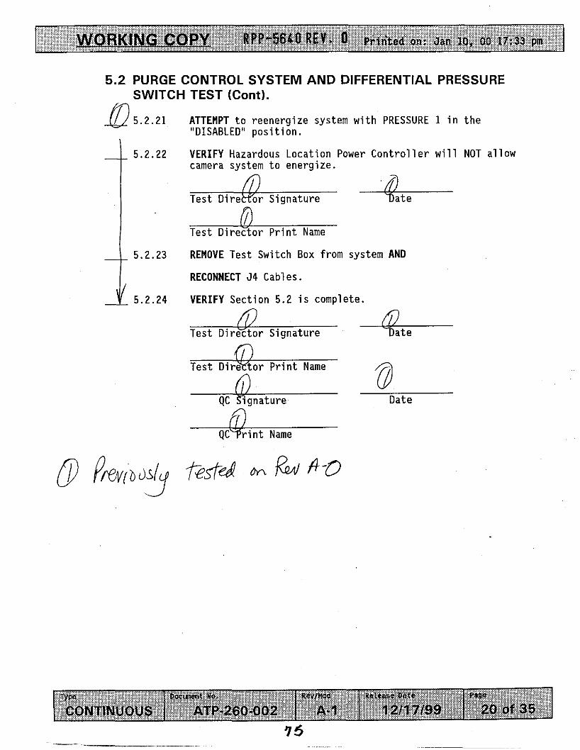
5.2.21
5.2.22
5.2.23
5.2.24
ATTEMPT t o reenerg ize system w i t h PRESSURE 1 i n t h e "DISABLED" p o s i t i o n .
VERIFY Hazardous Locat ion Power C o n t r o l l e r w i l l NOT a l l o w camera system t o energize.
! Test D i r e w o r S isnature -
P r i n t Name
REMOVE Test Switch Box f rom system AND
RECONNECT 54 Cables.
VERIFY Sect ion 5.2 i s complete.
/ Test D i r e y t o r S ignature
I Test D i r e y t o r P r i n t Name rn CII
Date
-@-- QC r i n t Name
7 5
W RPP-5640 REV. 0 P r t n ' t e d on: Jan 10, 00 17:33 pm 1
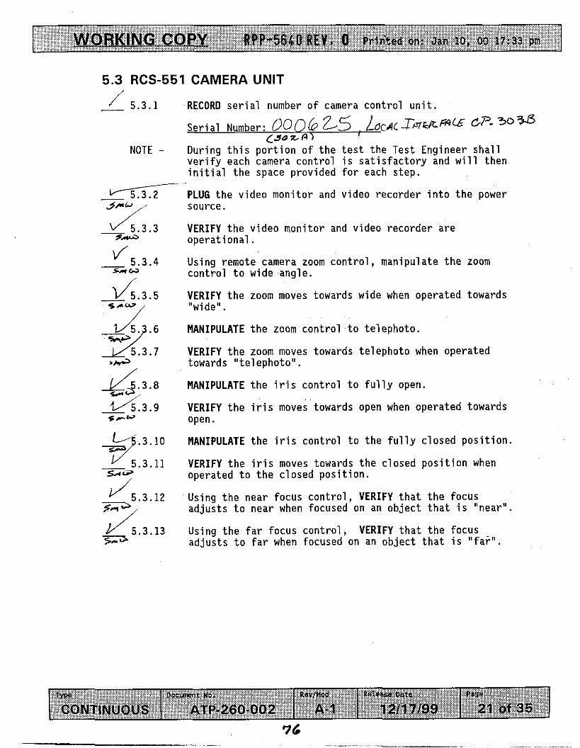
5.3 RCS-551 CAMERA UNIT
5 . 3 . 1 RECORD s e r i a l number of camera cont ro l u n i t .
NOTE - During t h i s po r t ion of t h e t e s t the Test Engineer shal l ve r i fy each camera cont ro l i s s a t i s f a c t o r y and will then i n i t i a l t h e space provided f o r each step.
- 5 . 3 . 4 / su w
- d . 3 . 5
M 5 . 3 . 7 *ha
4 3 . 8
g 5 . 3 . 9 s r w
2::::: sl+
d 5 . 3 . 1 2 P, d 5 . 3 . 1 3 F;-3
PLUG t h e video monitor and video recorder i n t o t h e power source.
VERIFY t h e video monitor and video recorder are ope ra t iona l .
Using remote camera zoom c o n t r o l , manipulate t h e zoom cont ro l t o wide angle .
VERIFY t h e zoom moves towards wide when operated towards "wide".
MANIPULATE t h e zoom cont ro l t o te lephoto .
VERIFY t h e zoom moves towards te lephoto when operated towards " te lephoto" .
MANIPULATE the i r i s cont ro l t o f u l l y open.
VERIFY t h e i r is moves towards open when operated towards open.
MANIPULATE t h e i r i s cont ro l t o t h e f u l l y c losed p o s i t i o n .
VERIFY t h e i r is moves towards t h e closed pos i t i on when operated t o t h e c losed pos i t i on .
Using t h e near focus c o n t r o l , VERIFY t h a t t h e focus a d j u s t s t o near when focused on an ob jec t t h a t i s "near" .
Using t h e f a r focus c o n t r o l , VERIFY t h a t t h e focus a d j u s t s t o far when focused on an ob jec t t h a t i s " f a r " .
76

WORKING CO PY UPP-56rSQ R E V - 0 Printed on: Jan IO, 00 ~ : 3 3 PN 1 5.3 pi CS-551 CAMERA UNIT (Cont).
5.3.15 CnD
5.3.16
- 5.3.17 se Ia
5.3.18
START Video Tape Recording.
While the camera i s focused on an ob jec t , VERIFY t h a t t h e p i c t u r e i s f r e e o f image de fec ts such as ghost images, p i c t u r e l ag , d i s t o r t i o n , hum, o r smearing.
PLAY BACK t he p r e v i o u s l y recorded t a p i n g o f t h e r e s o l u t i o n t e s t .
VERIFY t h a t t he v ideo recorder operates p r o p e r l y and t h a t t he image i s acceptable.
VERIFY Sect ion 5.3 i s complete.
/ - l o -ZOO0 Date
j - / i , - O O Date

v RPP-5640 REV, 0 Printed on: Jan 10, 00 17:33 pin 1 5.4 RCS-551 PAN AND TILT
NOTE - During this VERIFY each then initia
portion of the test the Test Engineer shall pan and tilt control is satisfactory and will
1 in the space provided for each step.
Using the remote pan control, pan in the clockwise direction until stop is reached.
RECORD the encoder readout for the position of the camera.
Encoder readinq: 3 5 $ deqrees
PAN in the counterclockwise direction until stop is reached.
RECORD the encoder readout.
Encoder readinq: 0 deqrees
VERIFY, using the readings from step 5 . 4 . 1 - 5.4.4 that the panning operation has covered 358 degrees.
Overall readino: 35 8 degrees
TILT the camera downward until the electronic stop position is reached.
RECORD the encoder readout.
Encoder readinq: 2L4 deqrees
TILT the camera up to the extreme upward position until the electronic stop position is reached.
RECORD the encoder readout.
Encoder readinq: 5-9 deqrees

1 WORKIN RPP-5640 BEY. 0 Printed on: Jan 10, 00 17:33 pm G COPY
5.4 RCS-551 PAN AND TILT (Cont).
- 5.4.10 VERIFY using t h e encoder readings from s t e p s 5.4.6 - 5.4.9 t h a t t h e t i l t has a range of 200 degrees min .
Overall readinq: 2 1 0 degrees
DE-ENERGIZE t h e pan and t i l t u n i t . - /<??l
VERIFY t h a t t h e pan and t i l t maintains i t ' s p o s i t i o n .
VERIFY Sect ion 5.4 i s comolete.
/ - / x - m Date
/ - / g - 0 0 Date

5.5 DETECTION OF MOVEMENT TEST
NOTE -
0 5.5.1
5.5.2
5.5.3
5.5.4
5.5.5
5.5.6
I
5.5.7 t 5.5.8 c
- 5.5.9
:..:
Two types of tests will be performed and data g&$ W be recorded on either the Specified Testing Tab'le OR the Discretionary Testing Table. The objective in this test section is t o determine the minimum detectable movement, at various distances, with the camera system. Adjustments such as lighting changes, camera adjustments etc. may be done at anytime during this section as directed by Test '
Director.
the Hazardous Location Power Controller .. .. %e the "ON" position AND
ENSURE POWER indicator is illuminated.
ENSURE purge supply is allowing flow through Hazardous Location Power Controller.
indicator is il l uminated.
is illuminated.
RECORD Test Date, and Camera system ID. number on applicable Testing Table.
PLACE a simulated dark background, carbon steel plate or other similar background as approved by Test director, a measured distance from the camera, AND
RECORD distance on applicable Test Table.
PLACE a simulated in-tank assembly BETWEEN the camera and the simulated background AND
RECORD component size, and distance on applicable Test Table.
ELIMINATE All non-camera light sources as completely-as possible, AND
RECORD any light sources still present on the Performance Log.
FOCUS camera on simulated assembly.
+h- IF ENSURE PURGING
ENSURE ENERGIZED indicator

5.5 DETECTION OF MOVEMENT TEST (Cont).
5.5.10 MOVE simulated assembly in 1/32" increments, until camera operator detects movement.
RECORD the distance moved on applicable Test Table.
RECORD any special camera adjustments, lighting changes, or any comments on applicable Test Table.
REPEAT steps 5.5.7 - 5.5.12 as directed by Test Director to determine minimum movement detectable.
VERIFY Section 5.5 is complete.
5.5.11
5.5.12
5.5.13
5.5.14
L Date
QC Signature Date
ii) QC rint Name
SI
R P P - 5 6 4 0 R E V . 0 ’
W I- < 0

RPP-5640 R E V . 0
Prjnted on: Jan 10, 00 17:33 pm WORKING C OPY WPP-5640 REV. 0
......................................................................
............................................
FIGURE 1
a I ! r
.....................................................................
CP-302A Local 220 vac ENCL-301 i 241 -AZ-156 Power source
rL :/ Camera Conbols
~
t - -
FLT.810 Unit
: CP302B : CP-303B
P c V - s l O ENCL-307 , . , . HLPC j ...............................
, R6504A ENERGIZED 101 101 PRESSURE 1
POWER 101 101 PRESSURE2 j PB-305
: PB-306
: CP-304
‘0 ‘0 0 ON/OFF RESET INLET PRESSURE Purge Une
.......
,I .......
\
.....
Local 1 10 vac , 1 Powersource
& Dlsconnect \ Prefix with A21 01 -WST-
Tank 241 -AZ-101 Camera 0 & M System RISER 168
AZ101 -WST-TV-301
/ lV CAMERA
LIGHTING UNIT

ORKING, COPY BPP-5640 REV. 0 Prin'ted on: Jan 10, 00 17:33 pm
i i m c S-Md.0 D C P w r m n o m WScrsen cmrn K.yborvd
00 0 0 0
FIGURE 2
S-Mdna DCPanrrn ii7n.Y
0 oow spnsam c-m n o 0 0 0
LOCAL INTERFACE UNIT ENCLOSURE AZ101 -WST-ENCL-307
AZ101 -WST-CP-3028 AZlOl-WST-CP303B
#I 1 Mate to 302 B M a s l Jnct. b x p-301)
#96 Mate to 302 B Gas MonRoring (CP-304)
#S Mate to 302 B Mast Jnct. Box (W-301)
118 Mate to CP-302 A (Ref. Fig. 1)
11 5 vac lo Gas Moniloring system
U15 Mate to 303 B Masl Jnct Box p401)
#39 Mate lo 303 B Gas Monltorlng (CP-304)
#13 Mate to 303 B Matt Jncr Box (lV301)
#8 Mate to CP- A (Rd. Fig. 1)
115vactoGao Monltohg System
HAZARDOUS LOCATION POWER CONTROLLER (HLPC)
PUROEH '
0 "
UPPER CAMERA AZ101-WST-lV-301
From From I ENCL-307 ENCL-907 1

t RPP-566QREV. 0 Pririted on: Jan 10, 00 17:33 pm
ATP PERFORMANCE EVENT
ATP PERFORMANCE LOG
T h i s page may be reproduced as necessary. Page 1 of __
DATE IN IT IALS

-COPY RQP-5840 REV. 0 Pritited on: Jan 10, 00 17:33 pm
Number
ATP EXCEPTION LOG
of - T h i s page may be reproduced as necessary. Page
Date Descr i p t i on

WORKING C OPY RPp-564aREY. .o Prinked on: Jan 10, 00 17:33 pm I
ATP STEP NUMBER:
ATP EXCEPTION RECORD
ATP EXCEPTION LOG#:
T h i s page may be reproduced as necessary. o f
TEST DIRECTOR SIGNATURE:
TEST ENGINEER SIGNATURE:
QUALITY ASSURANCE SIGNATURE:
Page
DATE :
DATE :
DATE :
I
DESCRIPTION OF EXCEPTION:
I N I T I A T O R NAME/ORGANlZATlON:
DATE OF EXCEPTION:
RESOLUTION OF EXCEPTION:

I RPf-56&OREY. 0 Printed on: Jan 10, 00 17:33 pm
PROCEDURE SIGNATURE SHEET
I N I T I A L S
rw P

I WORKING COPY ilPP-5640 BEY. 0 Prii-ked on: Jan 10, 00 17:33 pm
PROCEDURE HISTORY SIGNATURE SHEET
L a s t F u l l Revis ion: A-0
Release Date: 12/08/99
USQ Screening Number: N/A
Approval Designator: SQ
Cur ren t M o d i f i c a t i o n : A-0
USQ Screening Number: N/A
Approval Designator: SQ PCA Inco rpo ra ted : N/A
POSITION/ORG DELEGATE DATE
NCO/WTF V i c k i M i l l e r 12/7/99
- SOH R. Gu t ie r rez 12/8/99
w W.L. Adam 12/8/99
SAFTEY E r n i e Hurst 12/8/99
TWRS Rad Con Bob Brown 12/8/99
Envi ornmental T.A. D i l h o f f 12/8/99
Cos Ens/DST Garv T a r d i f f 12/7/99
Cos EauiD. Ens. R. Robinson 12/8/99
Acceptance Review David W. VanDvke 12/8/99
Approval A u t h o r i t y James Brvce 12/8/99
J u s t i f i c a t i o n : New Procedure.
Summary o f Changes: N/A
90

RPP-5640 REV. 0
8.0 ATTACHMENT 4 - ATP-260-002 REV. A- 1, TEST PHASE 3
91
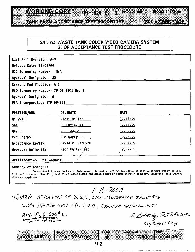
RPP-5640REV. 0 P r i n t e d on: Jan 10, 00 14:21 pm
TANK FARM ACCEPTANCE TEST PROCEDURE 241-AZ SHOP ATP
r w O o c m t No. Rev/W
CONTINUOUS ATP-260-002 A- 1
I 241-A2 WASTE TANK COLOR VIDEO CAMERA SYSTEM SHOP ACCEPTANCE TEST PROCEDURE I
Relellse Oete Page
1211 7/99 1 of 35
~
Last F u l l Revis ion: A-0
Release Date: 12/08/99
USQ Screening Number: N/A
Approval Designator : SQ
Current M o d i f i c a t i o n : A-1
USQ Screening Number: TF-98-1201 Rev 1
Approval Designator: Q PCA Incorporated: ETF-99-751
POSITION/ORG DELEGATE DATE
NCOlWTF V i c k i M i l l e r 12/17/99
- SON R. Gu t ie r rez 12/17/99
!N!x W.L. Adams 12/17/99
Coq Enq/DST W.M.Hartv Jr. 12/16/99
Acceptance Review David W . VanDvke 12/17/99
Rich Gu i te r ryez 12/17/99
’ J u s t i f i c a t i o n : Ops Request. /
Summary o f Changes: I n section 2.4 added i n General Information. I n section 5.0 various ed i tor ia l changes through-out procedure.
Section 5 . 2 changed Flow-Rate, Section 5 . 5 Added ENSURE and deleted part of steps as not neccessary. specif ied Table Changed distance requirements.
I
/ - I O -2900

- RPP-5640 REV . 0 Printed on: Jan 10. 00 14:21 pin
TABLE OF CONTENTS PAGE TEST EXECUTION SHEET . . . . . . . . . . . . . . . . . . . . . . . . . . 3
1.0 PURPOSE AND SCOPE . . . . . . . . . . . . . . . . . . . . . . . . . 4 1.1 PURPOSE . . . . . . . . . . . . . . . . . . . . . . . . . . . 4 . . . . . . . . . . . . . . . . . . . . . . . . . . . . . 4 1 . 2 SCOPE
2 . 0 INFORMATION . . . . . . . . . . . . . . . . . . . . . . . . . . . . 4 4 2 . 1 TERMS AND D E F I N I T I O N S . . . . . . . . . . . . . . . . . . . . .
2 . 2 R E S P O N S I B I L I T I E S . . . . . . . . . . . . . . . . . . . . . . . 4 7.3 REFERENCES . . . . . . . . . . . . . . . . . . . . . . . . . . 6 ... . ~~~~
2 . 4 GENERAL INFORMATION . . . . . . . . . . . . . . . . . . . . . . 7 2 . 5 RECORDS . . . . . . . . . . . . . . . . . . . . . . . . . . . . 10
3 . 0 PRECAUTIONS AND L I M I T A T I O N S . . . . . . . . . . . . . . . . . . . . 11 3.1 PERSONNEL SAFETY . . . . . . . . . . . . . . . . . . . . . . . 11
4 . 0 PREREQUISITES . . . . . . . . . . . . . . . . . . . . . . . . . . . 1 2 4 . 1 SPECIAL TOOLS. EQUIPMENT. AND SUPPLIES . . . . . . . . . . . . 1 2 4 . 2 CONDITIONS AND ACTIONS . . . . . . . . . . . . . . . . . . . . 13
5 . 0 PROCEDURE . . . . . . . . . . . . . . . . . . . . . . . . . . . . 1 4
5 . 3 RCS-551 CAMERA U N I T . . . . . . . . . . . . . . . . . . . . . . 2 1 5.4 RCS-551 PAN AND T I L T . . . . . . . . . . . . . . . . . . . . . 23 5 . 5 DETECTION OF MOVEMENT TEST . . . . . . . . . . . . . . . . . . 2 5
5 . 1 START UP AND PURGE SYSTEM TEST . . . . . . . . . . . . . . . 1 4 5 . 2 PURGE CONTROL SYSTEM AND DIFFERENTIAL PRESSURE SWITCH TEST . . 1 7
S P E C I F I E D TESTING TABLE . . . . . . . . . . . . . . . . . . . . . . . . . 2 7
DISCRETIONARY TESTING TABLE . . . . . . . . . . . . . . . . . . . . . . . 2 8
F I G U R E 1 . . . . . . . . . . . . . . . . . . . . . . . . . . . . . . . . 2 9
F I G U R E 2 . . . . . . . . . . . . . . . . . . . . . . . . . . . . . . . . 30
ATP PERFORMANCE LOG . . . . . . . . . . . . . . . . . . . . . . . . . . . 31
ATP EXCEPTION LOG . . . . . . . . . . . . . . . . . . . . . . . . . . . . 3 2
ATP EXCEPTION RECORD . . . . . . . . . . . . . . . . . . . . . . . . . . 3 3
PROCEDURE SIGNATURE SHEET . . . . . . . . . . . . . . . . . . . . . . . . 3 4
PROCEDURE HISTORY SIGNATURE SHEET . . . . . . . . . . . . . . . . . . . . 3 5
9 3
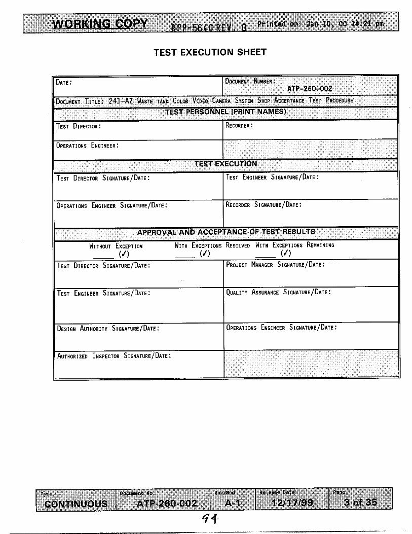
- - 0 R E V , 0 Printed on: Jan 10, 00 14:21 pm
D o E ~ i wc. Revmod Releaf& Dsto rype CONTINUOUS ATP-260-002 A- 1 12117199
TEST EXECUTION SHEET
PaBe
3 of 35
DAIE: DOCUMENT NUMBER: ATP-260-002
DOCLMENI TITLE: 241-AZ WASTE TANK COLOR V I D E O CAMERA S Y S I E M Shop ACCEPIAhCE TEST PROCEDURE
TEST PERSONNEL (PRINT NAMES)
11 I TESI DIRECTOR: I
O P E R A I l O h S E h C l N E E R :
TEST EXECUTION
TEST D~RECIOR S l G h A T L R E I D A I E : TESI ENGINEER S I G N A I U R E / D A I E :
DESIGN AUTHORIIY SICNATURE/DATE: O P E R A I I O N S ENGINEER SIGNATURE/DATE :
Au1.0~ I ZED INSPECTOR s I GNAT-RE / D A I E :

v RPP-564RREY. 0 Printed on: Jan 10, 00 14:21 pm
Type DosMont No, R e v h d Rotcase Date
CONTINUOUS ATP-260-002 A-1 1 2/17/99
1 .o PURPOSE AND SCOPE
1.1 PURPOSE
Paw 4 of 35
This procedure provides instructions to performing a Shop Acceptance Test Procedure for the 101 AZ camera system and camera purge gas (air) system.
1.2 SCOPE
This procedure shall demonstrate and document acceptance of the 241- AZ-101 Waste Tank Color Video Camera System, camera purge gas (air) system, and provides verification they function as designed.
The purge system functions will be tested verifying pressure and flow exists during camera system operation.
The purge control system functions will also be tested verifying automatic shutdown of in tank assemblies and electrical components is achieved upon loss of pressure. Functionality of differential pressure switches for operability and redundancy to show no single point failure exists in electrical shutdown system.
2.0 INFORMATION
2.1 TERMS AND DEFINITIONS
2.1.1 ALARA - - As Low As Reasonably Achievable
2.2 RESPONSIBILITIES
2.2.1 Test Engineer is responsible for the following:
All preparations for this Test have been completed
Support Test Director and Test Personnel with the technical information and support necessary to complete this procedure
2.2.2 Operation Personnel are responsible for operating the camera systems per the Test Engineer and Test directors direction.
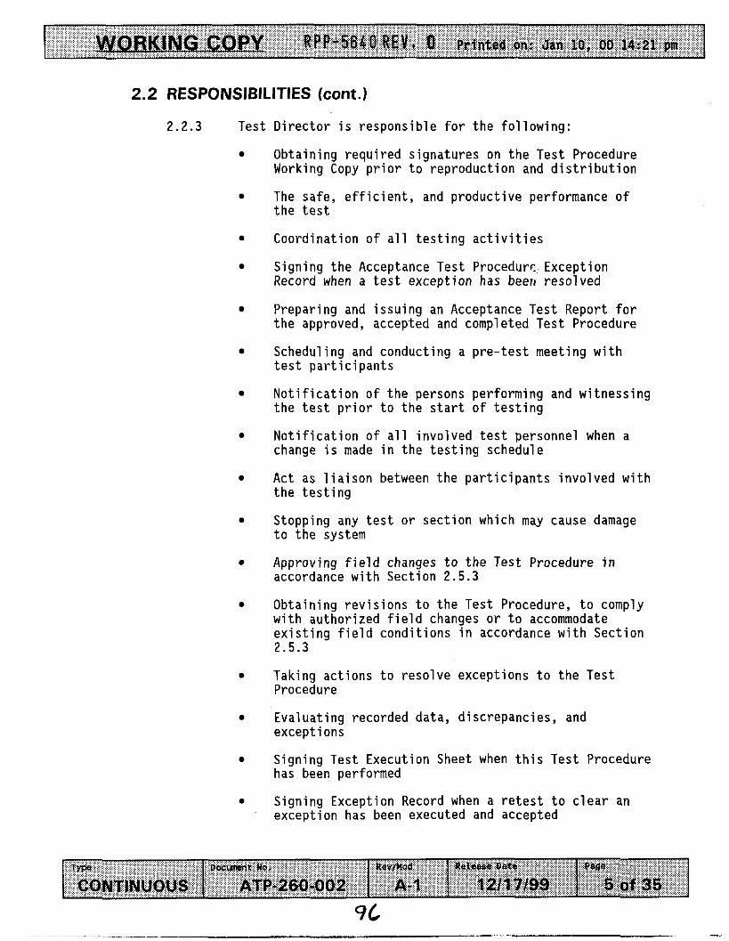
WORKING COPY RPP-5640 REV. 0 Printed on: Jan IO, 00 14:21 pm
T Y W O o C m t NO. Rev/ mod Release Date
CONTINUOUS ATP-260-002 A- 1 12/17/99
2.2 RESPONSIBILITIES (cont.)
Page
5 of 35
2.2.3 Test Director i s responsible for the following:
0
0
0
0
0
e
e
0
0
0
e
e
0
e
0
0
Obtaining required signatures on the Test Procedure Working Copy prior to reproduction and distribution
The safe, efficient, and productive performance of the test
Coordination of all testing activities
Signing the Acceptance Test Procedurc Exception Record when a test exception has beer1 resolved
Preparing and issuing an Acceptance Test Report for the approved, accepted and completed Test Procedure
Scheduling and conducting a pre-test meeting with test participants
Notification of the persons performing and witnessing the test prior to the start of testing
Notification of all involved test personnel when a change is made in the testing schedule
Act as liaison between the participants involved with the testing
Stopping any test or section which may cause damage to the system
Approving field changes to the Test Procedure in accordance with Section 2.5.3
Obtaining revisions to the Test Procedure, to comply with authorized field changes or to accommodate existing field conditions in accordance with Section 2.5.3
Taking actions to resolve exceptions to the Test Procedure
Evaluating recorded data, discrepancies, and exceptions
Signing Test Execution Sheet when this Test Procedure has been performed
Signing Exception Record when a retest to clear an exception has been executed and accepted

v Rpp-566Q R E V , 0 Printed on: Jan 10, 00 14:21 pm 1
T W D W m t He- Rav/Md R O l C ~ S O Date
CONTINUOUS ATP-260-002 A- 1 12ll7/99
2.2 RESPONSIBILITIES (cont.)
2.2.4 QC Inspec tor i s respons ib le f o r w i tness ing t e s t execut ion and s ign ing t h e completed sec t ions o f t h e t e s t .
The Author ized Inspec tor i s respons ib le f o r t h e f o l l o w i n g :
Witnessing t e s t execut ion
Approval and s ignature o f acceptance upon complet ion
2.2.5
o f t h i s procedure.
2.3 REFERENCES
2.3.1
2.3.2 Purchase S p e c i f i c a t i o n WHC-S-0410, Rev 2 (P.O.# W-408171),
Acceptance Test Report 241-AZ-101 Waste Tank Co lor Video Camera System WHC-SD-WM-ATR-181 Rev 0
"241-AZ-101, W151 Pro jec t , Suspended F i x t u r e and Weld Inspec t ion Camera System."
2.3.3 WHC-SD-W151-ETP-001, Rev. 1, "Engineer ing Task Plan f o r The 241-AZ-101 Waste Tank Color Video Camera System".
2.3.4 WHC-SD-WM-ATP-181, Rev. 0, "Acceptance Test Procedure 241-AZ-101 Waste Tank Color Video Camera System".
Pa@
6 of 35
97

2.4 GENERAL INFORMATION
T y p e Docunnt No. Rev/W Retease Date
CONTINUOUS ATP-260-002 A- 1 1 2fl7/99
2.4,3 Acceptance Test steps detailed in individual Tests fn Section 5.0 shall be performed sequentially, unless otherwise noted or as directed by the Test Director.
P.Ba
7 of 35
. . . . . . . . . . .
. . .
Any step that requires verificatiou o f data must include recording data on the Worktng Copy.

v RPP-5640 REV. 0 P r i n t e d on: Jan 10, 00 14:21 pm 1
rype D o c r n t no. Rev/Hod
CONTINUOUS ATP-200-002 A- 1
2.4 GENERAL INFORMATION (Cant).
2.4.5 Resolve t e s t except ions i n t h e f o l l o w i n g manner:
setsme Date Paue
12/17/99 a of 35
. Record the ac t i on taken t o reso lve each except ion i n the "Resolut ion o f Except ion" s e c t i o n o f the Acceptance Test Procedure Except ion Record.
When the a c t i o n taken r e s u l t s i n an acceptable r e t e s t , i n i t i a l and date the Cor rec t i on Approval sec t i on o f t he Except ion Sheet
When the a c t i o n taken does no t r e s u i t i n an acceptable r e t e s t , .prov ide a d e t a i l e d exp lanat ion o f why the r e t e s t a c t i o n was no t acceptable, and what a d d i t i o n a l p lans are requi red. The Test Englneer then s igns and dates the Resolut ion o f Except ion s e c t i o n o f t h e Acceptance Test Procedure Except ion Record, and ob ta ins any o ther approvals requ i red
NOTE - The f o l l o w i n g steps d e t a f l t h e poss ib le cond i t i ons t h a t may e x i s t a t t he complet ion o f t h e Acceptance Test Procedure, and t h e steps necessary t o complete acceptance i n those cond i t ions .
- RPP-5640 REV. 0 P r i n t e d on: Jan 10, 00 14:21 pm
Type
CONTINUOUS
2.4 GENERAL INFORMATION Gont).
2 . 4 . 7 The completed t e s t may be approved w i thou t t e s t except ions:
Check app l i cab le space on Test Exgcut lon Sheet t o show t h a t t he Acceptance Test Procedure has been performed and no except ions have bean recorded
Appropr ia te i n d i v i d u a l Test Performers w i l l s i gn and date t h e Test Execution Sheet i n the spaces prov ided
D i s t r i b u t e r e q u i s i t e copies as d i r e c t e d by t h e c l i e n t
Send the Master Copy o f t h e completed Acceptance Test Procedure t o the c l i e n t .
The completed t e s t may be approved w i t h except ions resalved:
2.4.8
D O C m t Yo. Revll(0d Release Detv P8ge
ATP-260-002 A- 1 12/17/99 9 of 35
Check app l icab le space on Test Execut ion Sheet t o show t h a t t h i s procedure has been performed w f t h except ions recorded and resolved
Appropr ia te i n d i v i d u a l Test Performers w i l l s i g n and date the Test Execut ion Sheet Cn the spaces prov ided
D i s t r i b u t e r e q u i s i t e coples as d i r e c t e d by t h e c l i e n t
Send t h e Master Copy o f the completed Acceptance Test Procedure t o the c l i e n t .
WORKING COPY ~ p p - 5 6 4 0 REV, 0 Printed on: Jan 10, 00 14:21 pm
Typa O o c m t No. Rev/ nad
COMflNUOUS ATP-280-002 A- 1
2.5 RECORDS
ReleBbe Date mu* 12117/99 10 of 35
2.5.1 All personnel involved i n the performance o f th is t e s t shall sign i n Procedure Signature Sheet.

ORKING COPY Rpp-5640 R E V , 0 Printed on: Jan 10, 00 14:21 pm
type QOcunent NO. R W I W Retease Dete
CONTiNUOUS ATP-260-002 A- 1 1 a1 7/99
3 .O PRECAUTIONS AND LIMITATIONS
3.1 PERSONNEL SAFETY
Papa
11 of35
3 . 1 . 1 If the performance of this procedure is suspended for any reason, ensure the equipment is left in a safe state.
3.1.2 All lockouts and tagouts or over-tagging requirements shall be performed in accordance with Tank Farm Administration Manual, HNF-IP-0842, Vol 11, Section 4 . 9 . 1 .
If any equipment problem is observed during the performance of this procedure, immediately notify the Test Director.
All fittings and safety devices such as whips and clamps pertaining to the compressed air system and associated hoses, SHALL be inspected prior to valving in the air.
procedure and personnel shall take precautions to ensure back strain, pinchpoints and protective clothing are observed.
3 . 1 . 3
3.1.4
3 . 1 . 5 Proper lifting techniques shall be utilized throughout the

WORKING COPY RPP-5640 B E Y . fl Printed on: Jan 10, 00 14:21 pm
T y p e D O C m t NO. Rev/ mad
CONTINUOUS ATP-260-002 A- 1
4.0 PREREQUISITES
4.1 SPECIAL TOOLS, EQUIPMENT, AND SUPPLIES
The f o l l o w i n g supp l ies may be needed t o per form t h i s procedure:
Xeioasa Date page
1 21 1 7199 12 of 35
4.1.1
4.1.2
4.1.3
4 . 1 . 4
4.1.5
4.1.6
Flowmeter (Per Test Engineer)
Stopwatch
CAMERA ASSEMBLY SYSTEM
Camera Mast
Pan And T i l t U n i t
Overview Camera
FIELD UNITS
Local I n t e r f a c e U n i t
Hazardous Locat ion Contro l Panel
Mobi le A i r Compressor
CAMERA CONTROLS
Camera, Pan and T i l t , and L i g h t i n g Con t ro l s
S Video Color Video Mon i to r
Keyboard
VCR and videotape
Misc. op t i ona l v ideo measurement and enhancement
Two 75 w a t t halogen l i g h t s
equipment.
TEST FIXTURES
L i f t i n g Adapters / Adapters
Simulated I n Tank Components

WORKING COPY RPP-5640 REV, 0 Printed on: Jan 10, 00 14:21 pm 1
D O C m t NO. Rev/ Mad Release Date Type
CONTINUOUS ATP-260-002 A- 1 12/17/99
4.2 CONDITIONS AND ACTIONS
Pag4
13 of 35
4.2.1 ENSURE a l l t e s t personnel have been b r i e f e d on t h e hazards and r e s p o n s i b i l i t i e s i n c l u d i n g a Job Hazard A n a l y s i s p r i o r t o p e r f o r m i n g t h i s t e s t .
2 l9 / / i 0 /z-lJv?5 t e s t K i r e c t o r S ignatQre ' Date
R G&- Test D i r e c t o r P r i n t Name
4.2.2 VERIFY t h e camera, and camera purge ( a i r ) systems a r e assembled.
Tes t D i r e c t o r S ign&ure w 7 U f t e ; y . e z
Test D i r e c t o r P r i n t Name
QC Witness s i g n below v e r i f y i n g t h a t i n s t r u m e n t a t i o n l i s t e d below has been c a l i b r a t e d and a c u r r e n t c a l i b r a t i o n s t i c k e r i s a f f i x e d .
Flowmeter (0.5-4 cfm) OR accep tab le s u b s t i t u t e p e r
4.2.3
Tes t Engineer.
I D Number: 02 Cal . Due Date: m A m
Date QC S i g n a t u r e
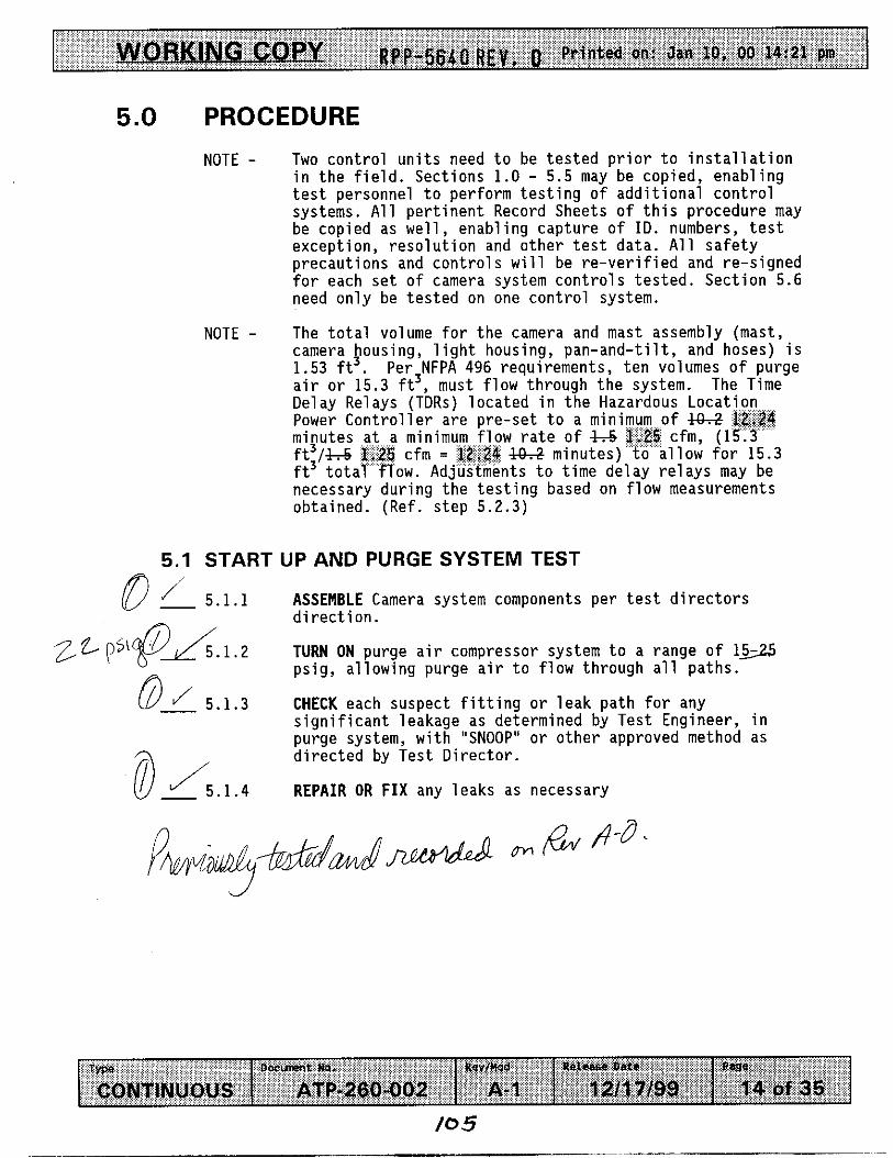
Printed on: Jan 10, 00 14:21 pm v llPP-5640 REV. 0
rype o a c m t no. Rev/ hod ReieabQ Date
CONTINUOUS ATP-200-002 A- 1 1211 '7199
5.0 PROCEDURE
Psse
14 of 35
NOTE - Two control units need to be tested prior to installation in the field. Sections 1.0 - 5.5 may be copied, enabling test personnel to perform testing o f additional control systems. All pertinent Record Sheets o f this procedure may be copied as well, enabling capture of ID. numbers, test exception, resolution and other test data. All safety precautions and controls will be re-verified and re-signed for each set of camera system controls tested. Section 5.6 need only be tested on one control system.
NOTE - The total volume for the camera and mast assembly (mast, camera housing, light housing, pan-and-tilt, and hoses) is 1.53 ft3. Per3NFPA 496 requirements, ten volumes o f purge air or 15.3 ft , must flow through the system. The Time Delay Relays (TDRs) located in the Hazardous Location Power Controller are pre-set to a mini
w rate o f 4 4 4 minutes) low for 15.3 nts to time delay relays may be
necessary during the testing based on flow measurements obtained. (Ref. step 5.2.3)
5.1 START UP AND PURGE SYSTEM TEST
ASSEMBLE Camera system components per test directors direction.
TURN ON purge air compressor system to a range of 1- psig, allowing purge air to flow through all paths.
CHECK each suspect fitting or leak path for any significant leakage as determined by Test Engineer, in purge system, with "SNOOP" or other approved method as directed by Test Director.
REPAIR OR FIX any leaks as necessary
0 J 5.1.1
zz-" p " @ A . 1 . 2
01 5.1.3
OJ5.1.4
/o 5
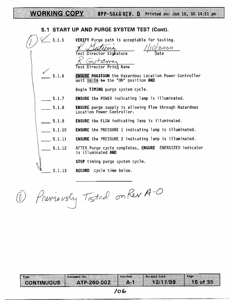
v RPP-5640REY. 0 Printed on: Jan 10, 00 14:21 pm
T y p e D W m t ND. Rev/nod
CONTINUOUS ATP-260-002 A- 1
5.1 START UP AND PURGE SYSTEM TEST (Cont).
Reisese Date Pape
12/17/99 15 of 35
0 'd 5.1.5
- 5.1.9
- 5.1.10
- 5.1.11
- 5.1.12
4- 5.1.13
h is acceptable for testing.
the Hazardous Location Power Controller %e the "ON" position AND
Begin TIMING purge system cycle.
ENSURE the POWER indicating lamp is illuminated.
ENSURE purge supply is allowing flow through Hazardous Location Power Control 1 er.
ENSURE the FLOW indicating lamp is illuminated.
ENSURE the PRESSURE 1 indicating lamp is illuminated.
ENSURE the PRESSURE 2 indicating lamp is illuminated.
AFTER Purge cycle completes, ENSURE ENERGIZED indicator is illuminated AND
STOP timing purge system cycle.
RECORD cycle time below.
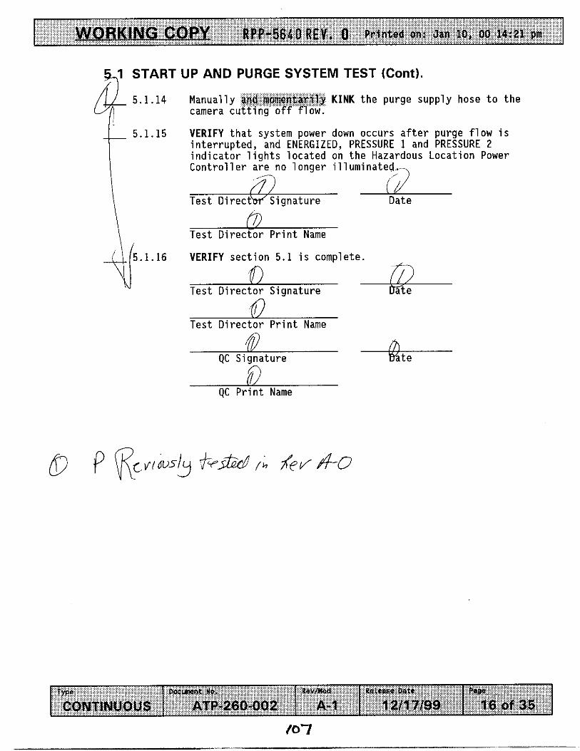
!$,I START UP AND PURGE SYSTEM TEST (Cont).
w e D O c W t NO. R e v f W Release Oats
CONTINUOUS ATP-260-002 A- 1 1 211 7199
5.1.14 Manually KINK t h e purge supply hose t o the camera cu
P I W 18 of 35
5.1.15 VERIFY t h a t system power down occurs a f t e r purge f l o w i s i n t e r r u p t e d , and ENERGIZED, PRESSURE 1 and PRESSURE 2 i n d i c a t o r l i g h t s l oca ted on t h e Hazardous Locat ion Power Contro l1 e r are no 1 onger i 11 uminated, t
i Test D i rec tb r 'S igna tu re Date rn Test D i r e c t o r P r i n t Name
5.1.16 VERIFY sec t i on 5 .1 i s complete.
Test D i r e c t o r S ignature
fl @ 0
Test D i r e c t o r P r i n t Name
QC S ignature
QC P r i n t Name
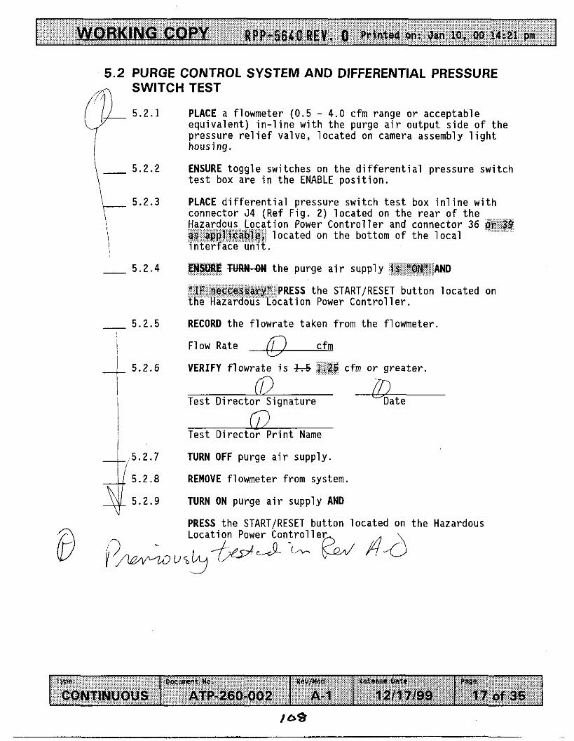
v RPP-5640REV. 0 Printed on: Jan 10, 00 14:21 pm I
Type D o c m t NO.
CONTINUOUS ATP-260-002
5.2 PURGE CONTROL SYSTEM AND DIFFERENTIAL PRESSURE SWITCH TEST m
Rov/Mod Release Date Pane
A- 1 1211 7/99 17 of 35
( /l 5.2.1
5.2.2
5.2.3
- 5.2.4
- 5.2.5
~ 4 5.2.6 I
I I
5 .2.7
5.2.8
5.2.9
PLACE a flowmeter (0.5 - 4.0 cfm range or acceptable equivalent) in-line with the purge air output side of the pressure relief valve, located on camera assembly light housing . ENSURE toggle switches on the differential pressure switch test box are in the ENABLE position.
PLACE differential pressure switch test box inline with connector 54 (Ref Fig. 2) located on the rear of the
tion Power Controller and connector 36 1 ocated on the bottom of the 1 oca1
TM" the purge air supply AND
PRESS the START/RESET button located on cation Power Controller.
RECORD the flowrate taken from the flowmeter.
Flow Rate cfm
VERIFY flowrate is k-5 cfm or greater.
Date (i3
Test Director Signature /s\ A
Test Director Print Name
TURN OFF purge air supply.
REMOVE flowmeter from system.
TURN ON purge air supply AND
PRESS the START/RESET button located on the Hazardous Location Power Controller,

WORKING COPY Rpp-5640 REV, .o P r i n t e d on: Jan 10, 00 14:21 pm 1
r w D o C r n t so. Rev/ w CONTINUOUS ATP-260-002 A-1
5.2 PURGE CONTROL SYSTEM AND DIFFERENTIAL PRESSURE SWITCH TEST (Cont).
5.2.10
Relase Dete Paw 12ll7199 18 of 35
ENSURE PURGING i n d i c a t o r i s i l l u m i n a t e d .
5.2.11
5.2.12
- I 5.2.13
5.2.14
5.2.15
5.2.16
ENSURE ENERGIZED, PRESSURE 1, PRESSURE 2, and FLOW i n d i c a t o r s a r e i l l u m i n a t e d .
PRESSURE 1 l o c a t e d on t h e t e s t s w i t c h box, SABLE p o s i t i o n AND
VERIFY camera c o n t r o l and l i g h t i n g system power i s d i s a b l e d . -
(7) Test D i r e c t o r S i g n a t u r e Date
/i> Test D i r e k f o r P r i n t Name
. . . . . . . . . . . . P S I W J N PRESSURE 1 h t h e "ENABLE" p o s i t i o n .
PRESS t h e "START/RESET" b u t t o n AND
ENSURE PURGING i n d i c a t o r i s i l l u m i n a t e d .
AFTER Purge c y c l e completes, ENSURE ENERGIZED, PRESSURE 1, PRESSURE 2, and f l o w i n d i c a t o r s a re i l l u m i n a t e d .
PRESSURE 2 l o c a t e d on t h e t e s t s w i t c h box, ISABLE" p o s i t i o n AND
VERIFY camera c o n t r o l and l i g h t i n g system power i s d i s a b l e d .
Tes t D i r e c t o r S i q n a t u r e Date L Test D i r e c t o r P r i n t Name

v R P P - 5 6 4 D R E V . 0 Printed on: Jan 10, 00 14:21 pm
T k W Docunent No. RevfMd Retease Oats
CONTINUOUS ATP-260-002 A- I 12/17199
5.2 PURGE CONTROL SYSTEM AND DIFFERENTIAL PRESSURE SWITCH TEST (Cont).
Page
19 of 35
& 5.2.17 ATTEMPT t o r e e n e r g i z e system w i t h PRESSURE 2 i n t h e "DISABLED" p o s i t i o n . I t 5.2.18 VERIFY Hazardous L o c a t i o n Power C o n t r o l l e r w i l l NOT a l l o w camera c o n t r o l and l i g h t i n g system t o energ ize .
1 Test D i r e c t 6 - S i g n a t u r e Date
?
I) Test D i r e c t o r P r i n t Name
5.2.19 P€SF" PRESSURE 2 & t h e "ENABLE" p o s i t i o n .
5.2.20 PRESSURE 1 +e t h e "DISABLE" p o s i t i o n AND
VERIFY camera c o n t r o l and l i g h t i n g system power i s d i s a b l e d .
Tes t D i r e c t o r S i g n a t u r e Date
0 Test D i r e c t o r P r i n t Name

v WP-56COREW. 8 P r i n t e d on: Jan 10, 00 14:21 pm I
rypa D o C u m t No. Rev/)Md
CONTINUOUS ATP-260-002 A- 1
5.2 PURGE CONTROL SYSTEM AND DIFFERENTIAL PRESSURE ~ SWITCH TEST (Cont).
5.2 .21 ATTEMPT t o r e e n e r g i z e system w i t h PRESSURE 1 i n t h e
5.2.22 VERIFY Hazardous L o c a t i o n Power C o n t r o l 1 e r w i 11 NOT a1 1 ow
"DISABLED" p o s i t i o n .
camera system t o energ ize . -
Retesse Dale Page
1211 7199 20 of 35
f l i;/i Test D i r K t o r S i g n a t u r e Date
0 Test D i r e c t o r P r i n t Name
5.2.23 REMOVE Test Swi tch Box f rom system AND
RECONNECT 54 Cables.
VERIFY S e c t i o n 5.2 i s complete.
Tes t D i r e c t o r S i g n a t u r e Date 65)
5.2.24
D (i)
@ Test D i r e c t o r P r i n t Name
Date QC S i g n a t u r e
69 QC P r i n t Name
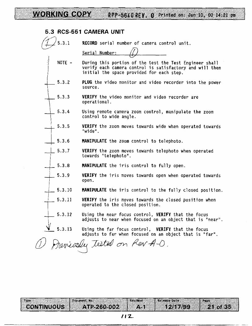
- Rpp-5640 R E V , 0 Printed on: Jan 10, 00 14:21 pm
T y p e
CONTINUOUS
5.3 RCS-551 CAMERA UNIT
D w m t No. R % v t W Releese Date P W
ATP-260-DOZ A-1 1 a1 7/99 29 of 35
5.3.1 @ NOTE -
5.3.2
5.3.3 k 5.3.4 5.3.5
5.3.6
5.3.7
5.3.8
4 5.3.9 I
5.3.10
5.3.11
5.3.12
4 5.3.13
RECORD s e r i a l number of camera cont ro l u n i t .
Se r i a l Number: l During t h i s port ion of t h e t e s t t h e Test Engineer sha l l v e r i f y each camera cont ro l i s s a t i s f a c t o r y and will t h e n i n i t i a l t h e space provided f o r each s t e p .
PLUG t h e video monitor and video recorder i n t o t h e power source.
VERIFY t h e video monitor and video recorder a r e ope ra t iona l .
Using remote camera zoom c o n t r o l , manipulate t h e zoom cont ro l t o wide angle .
c/
VERIFY t h e zoom moves towards wide when operated towards "wide".
MANIPULATE t h e zoom cont ro l t o te lephoto .
VERIFY t h e zoom moves towards te lephoto when operated towards " te lephoto" . MANIPULATE t h e i r i s cont ro l t o f u l l y open.
VERIFY t h e i r i s moves towards open when operated towards open.
MANIPULATE t h e i r i s control t o t h e f u l l y c losed p o s i t i o n .
VERIFY the i r i s moves towards the closed pos i t i on when operated t o t h e closed pos i t i on .
Using t h e near focus con t ro l , VERIFY t h a t t h e focus a d j u s t s t o near when focused on an ob jec t t h a t i s "near" .
Using t h e far focus c o n t r o l , VERIFY t h a t the focus a d j u s t s t o far when focused on an ob jec t t h a t i s " fa r" .

v UPP-564OREil. 0 Printed on: Jan lo, 00 14:21 pm
fW Docuwtt No.
CONTINUOUS ATP-260402
5.3 RCS-551 CAMERA UNIT (Cont).
Rev/md Retease Date P W
A- 1 12ll7199 22 of 35
@ 5.3.14
5.3.15
5.3.16
5.3.17
5.3.18
START Video Tape Recording.
While t h e camera i s focused on an o b j e c t , VERIFY t h a t t h e p i c t u r e i s f r e e o f image de fec ts such as ghost images, p i c t u r e l a g , d i s t o r t i o n , hum, o r smearing.
PLAY BACK the p r e v i o u s l y recorded t a p i n g o f t h e r e s o l u t i o n t e s t .
VERIFY t h a t the v ideo reco rde r operates p r o p e r l y and t h a t t h e image i s acceptable.
VERIFY Sect ion 5.3 i s complete.
Test D i r e c t o r Signature
Test D i r e c t o r P r i n t Name
(29 i%, Date
0 f i7 W 2 i j g n a t u r e r
(59 QC P r i n t Name

WORKING COPY PPP-564OREP. 0 Printed on: Jan 10, 00 14:21 pm
r. -_ 5.4.2 RECORD the encoder readout for the position of the camera.
Encoder readinq: - / deqrees
5.4.3 PAN in the counterclockwise direction until stop is
5.4 RCS-551 PAN AND TILT
reached.
RECORD the encoder readout.
Encoder readinq: deqrees
the panning operati as covered 358 degrees.
Overall readinq: deqrees
position is reached.
__ 5.4.4
-_ 5.4.5 VERIFY, using the readings from step 5.4.1 - 5.4.4 that
-_ 5.4.6 TILT the camera downward until the electronic stop
__ RECORD the encoder re out. 5.4.7 49 deqrees Encoder readinq:
TILT the camera up to the extreme upward position until the electronic stop position is reached.
-_ 5.4.8
Type D D c m t No.
CONTINUOUS ATP-260-002 Revmad Ueleam Date P w e
A- 1 12/17/99 23 of 35

5.4 RCS-551 PAN AND TILT (Cont).
& 5.4.10 VERIFY using the encoder readings from steps 5.4.6 - 5.4.9 t h a t the t i l t has a range o f 200 degrees m i n .
Overall readinq: 21 I deqrees a 5.4.11
5.4.12
5.4.13
DE-ENERGIZE the pan and t i l t uni t .
VERIFY that the pan and t i l t maintains i t ' s pos i t ion .
VERIFY Section 5.4 i s complete.
Test DirecGr Signature Date f rg
Typa D W m t NO. Rev/md Release Date
CONTINUOUS ATP-200-002 A- 1 12/17/99
Test Direcyox Print Name
Pegs
24 of 35
QC SGnature Date

WORKING COPY f&@!Wl?REV. a Printed on: Jan 10, 00 14:21 pm
rype O o c l n m t No.
CONTINUOUS ATP-260-002
5.5 DETECTION OF MOVEMENT TEST
Rev/ nod Petease Date PIBe
A- 1 1211 7/99 25 of 35
NOTE -
0 5.5.1 L 5.5.2
I
5.5.3
5.5.4
5.5.5
5.5.6
5.5.7
5.5.8 L 5.5.9
Two types o f t e s t s w i l l be per formed and d a t a be recorded on e i t h e r t h e S p e c i f i e d T e s t i n g Ta D i s c r e t i o n a r y T e s t i n g Table. The o b j e c t i v e i n t h i s t e s t s e c t i o n i s t o determine t h e minimum d e t e c t a b l e movement, a t v a r i o u s d is tances , w i t h t h e camera system. Adjustments such as l i g h t i n g changes, camera adjustments e t c . may be done a t anyt ime d u r i n g t h i s s e c t i o n as d i r e c t e d by T e s t D i r e c t o r .
t h e Hazardous L o c a t i o n Power C o n t r o l l e r he "ON" p o s i t i o n AND
ENSURE POWER i n d i c a t o r i s i l l u m i n a t e d .
ENSURE purge supp ly i s a l l o w i n g f l o w th rough Hazardous L o c a t i o n Power C o n t r o l l e r .
ENSURE PURGING i n d i c a t o r i s i l l u m i n a t e d .
i s i l l u m i n a t e d .
RECORD Test Date, and Camera system I D . number on a p p l i c a b l e T e s t i n g Table.
PLACE a s i m u l a t e d d a r k background, carbon s t e e l p l a t e o r o t h e r s i m i l a r background as approved by Tes t d i r e c t o r , a measured d i s t a n c e f r o m t h e camera, AND
RECORD d i s t a n c e on a p p l i c a b l e Test Table.
PLACE a s i m u l a t e d i n - t a n k assembly BETWEEN t h e camera and t h e s i m u l a t e d background AND
RECORD component s i z e , and d i s t a n c e on a p p l i c a b l e T e s t Tab1 e.
ELIMINATE A l l non-camera l i g h t sources as c o m p l e t e l y as p o s s i b l e , AND
RECORD any l i g h t sources s t i l l p resent on t h e Performance
FOCUS camera on s i m u l a t e d assembly.
ENSURE ENERGIZED i n d i c a t o r
Log.

NORKING COPY RPP-5640REY. O Printed on: Jan IO, 00 14:21 pm
T y p e Dwwt W. R e v / W Rekcme Oats
CONTINUOUS ATP-260-002 A- 1 1211 7199
5.5 DEJECTION OF MOVEMENT TEST (Cont).
Paae
20 of 35
a 5.5.10
5.5.11
5.5.12 I
5.5.13
5.5.14
MOVE simulated assembly in 1/32" increments, until camera operator detects movement.
RECORD the distance moved on applicable Test Table.
RECORD any special camera adjustments, lighting changes, or any comments on applicable Test Table.
REPEAT steps 5.5.7 - 5.5.12 as directed by Test Director to determine minimum movement detectable.
VERIFY Section 5.5 is complete.
/7 Test DirectorwSignature
/ Test Directol.i/Print Name
Date @
QC Signature
QC Prwt Name (/
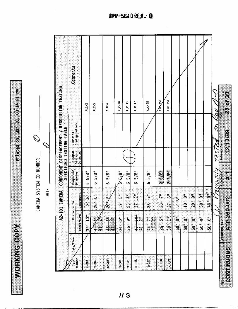
RPIP-!5640 REN. Q
w I- 4 0
1 4
. Y) Y)
W W
II a

RPP-5640 REh. 0
I
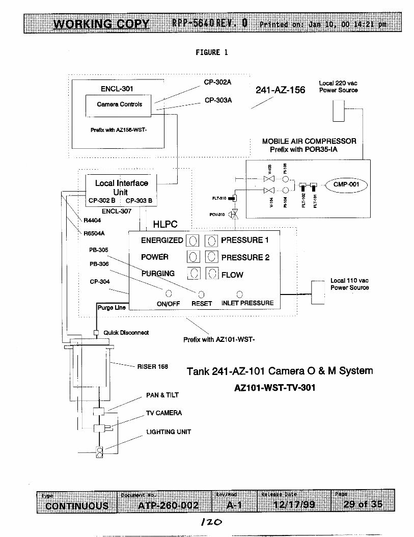
ORKING COP Y RPP+SCO R E Y 0 Printed an: Jan IO, 00 14:21 pm
- ~
FLTJlO \ I CP302B ~ CP-303B
ENCL-307 pcv-310 y 244404
~ RE504A HLPC i . . . . . . . ~ ~ . . . ~ ~~~~~ ~~~ . . . . . . ~ . . . . . . . . . .
ENERGIZED mi nl PRESSURE 1 1
FIGURE 1
D O C m t NO. Revf mod ReiebsO Date T y p e
CONTINUOUS ATP-260-002 A- 1 12/17/99
CP-302A ENCL-301
CP-303A Camera Controls
PreRX with AZ156-WST-
Page
29 of 35
Local 220 vac 241 -M-l!j6 Power Source
MOBILE AIR COMPRESSOR Prefix with POR35-IA
VIM
POWER Dl (01 PRESSURE 2
Local 1 10 vac Power Source
Prefix with AZ101-WST-
Tank 241 -AZ-1 01 Camera 0 & M System RISER 168
AZ101-WST-TV-301
LIGHTING UNIT

WORKING COPY ~ p p - 5 6 ~ ~ ~ ~ ~ . 0 Printed on: Jan 10, 00 14:21 pm
D O C m 1 NC. Rev/)(ad Release Dele rvpe CONTINUOUS ATP-280-002 A- 1 1 a1 '7199
FIGURE 2
PI08
30 of 35
LOCAL INTERFACE UNIT ENCLOSURE AZ101 -WST-ENCL-307
Mi01 -WST-CPQO2B
';1 AZlOl-WST-CP-303B
39 15 0 0
0 0 0 8 13 I l 5vac
Y l 1 Mate to 302 B Matt Jnd. Box OV-301)
#36 Mate to 302 B Gas Monhoting (CP-304)
#9 Male to 302 B Mast Jnn. Box (rv-301)
#B Mate to CP-302 A (Ref. Fig. 1)
11 5 vac Io Gas Monitoring System
Y15 Mate to 303 B Masf JncL Box (Tv-301)
#39 Mate to 303 B Gas MonHoting (CP-304)
813 Mate to 303 B Matt Jnd. Box (TV301)
Y8 Male to CP-303 A (Ref. Flp. 1)
11 5 VBC to Gas Monllorlng Sy8tern
HAZARDOUS LOCATION POWER CONTROLLER (HLPC)
I I
UPPER CAMERA AZ101-WST-lV-301
PURGE IN ENCL-307 ENCL-907

v RPP-564QREV. 0 Printed on: Jan 10, 00 14:21 pm 1
O w m t NO. Rev/ Hod rw CONTINUOUS ATP-280-002 A- 1
ATP PERFORMANCE LOG
T h i s page may be reproduced as necessary. Page I o f -
aeteese Date Page
12/17199 31 of 35

- R P P - 5 6 k Q B E V a O Printed on: Jan 10, 00 14:21 pm
Number Date
ATP EXCEPTION LOG
T h i s page may be reproduced as necessary. Page o f
Description
T y p e D W m t ND. Rev/Wad
CONTINUOUS ATP-260-002 A- 1 uutoQ-se Pats P8W
1 2/17/99 32 of 35
lz.3

- RPP-5640REy* Printed on: Jan 10, 00 14:21 pm
TEST DIRECTOR SIGNATURE:
TEST ENGINEER SIGNATURE:
ATP EXCEPTION RECORD
DATE :
DATE :
T h i s page may be reproduced as necessary. o f
QUALITY ASSURANCE SIGNATURE :
Page
DATE :
ATP STEP NUMBER: ATP EXCEPTION LOG#:
T y p a D W m t No.
CONTINUOUS ATP-260-002
I
DESCRIPTION OF EXCEPTION:
Rev/ nod (taleaae Date Page
A- 1 la1 7199 33 of 35
I N I T IATOR NAMEIORGAN I ZAT I ON :
DATE OF EXCEPTION:
RESOLUTION OF EXCEPTION:
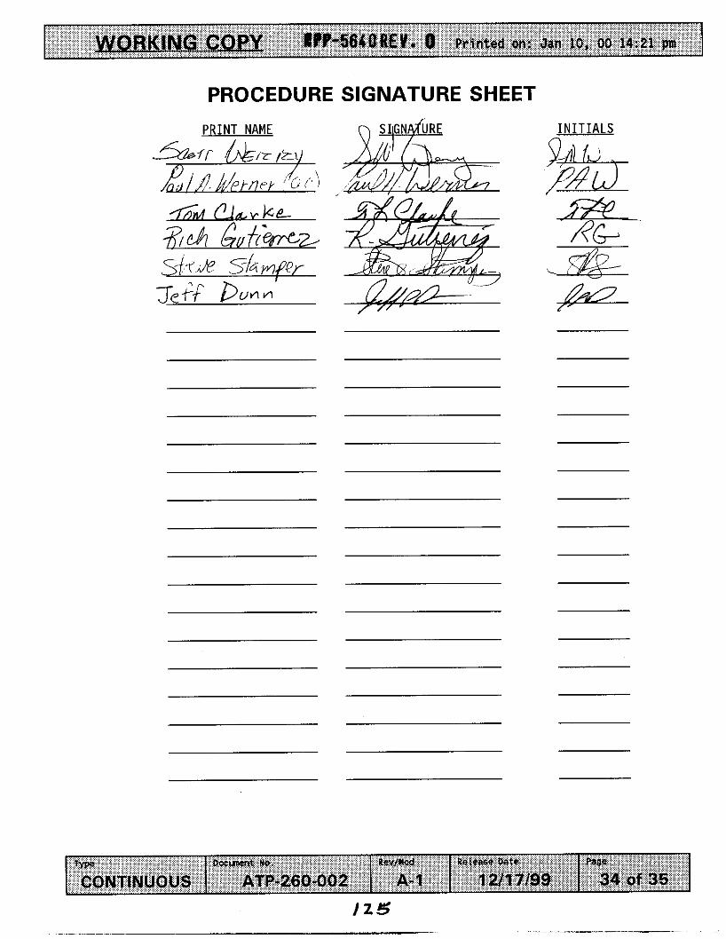
T y p e D O S m t W. RUV/)cad setcase gats
CONTINUOUS ATP-260-002 A- 1 1 a1 7/99 ?we
34 of 35
PROCEDURE SIGNATURE SHEET
I N I T I A L S
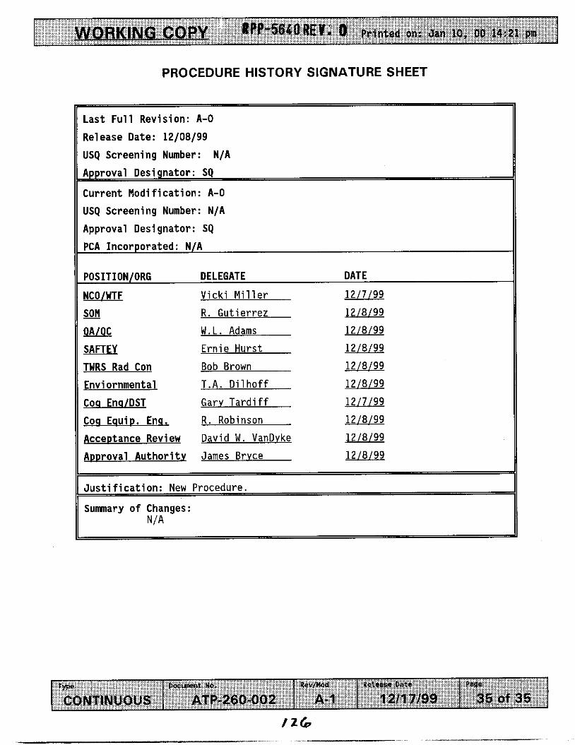
PROCEDURE HISTORY SIGNATURE SHEET
DoslnIent NO. Revfmd Retease Date Type
CONTINUOUS ATP-260-002 A- 1 12/17/09
Last F u l l Revis ion: A-0
Release Date: 12/08/99
USQ Screening Number: N/A
Approval Designator : SQ
Current M o d i f i c a t i o n : A-0
USQ Screening Number: N/A
Approval Designator: SQ PCA Incorporated: N/A
P8ga
35 of 35
POSITION/ORG DELEGATE DATE
NCOlWTF Vicki Miller 12/7/99
- SON R. Gutierrez 12/8/99
w W.L. A d a m 12/8/99
SAFTEY Ernie Hurst 12/8/99
TWRS Rad Con Bob Brown 12/8/99
Envi ornmental T.A. Dilhoff 12/8/99
Coq Enq/DST Garv Tardiff 12/7/99
Coq EauiD. E m . R. Robinson 12/8/99
Acceptance Review David W . VanDvke 12/8/99
ADproval A u t h o r i t y James Brvce 12/8/99
J u s t i f i c a t i o n : New Procedure.
Summary o f Changes: N/A

RPP-5640 REV. 0
9.0 ATTACHMENT 5 - MACRO SCALE MEASUREMENTS USING CCTV MICROMETER MEMORANDUM

PPP-st4a &to
9.0 d.rrrlc*RAeut5
MEMORANDUM
TO: Alan Carlson FROM: Scott Weny, Dennis Douglas SUBJECT: Macro Scale Measurements Using CCTV Micrometer
In mid-December 1999, a series of shop tests were performed on the CCTV and Colorado Video system. These tests served two purposes. First, they all owed the CCTV system to be functionally checked prior to installing it in AZ-101. Second, they allowed to optical performance of the system to be assessed in terms of resolution, contrast, illumination, and so on.
CC: Jim Homan, Dave Smet
~
An analysis of the imaged data, based upon the operator logs recorded during the tests, was performed immediately after the tests. This analysis focussed on the fine-scale resolving capabilities of the CCTV measurement system. The results of the analysis showed that the CCTVhicrometer system is expected to be able to reliably measure the displacements of objects in AZ-101 as small as US”, or so‘.
At the other extreme, a test was performed where a ruler was placed in the CCTV field of view at a distance of about 33-feet from the camera. The “0” of the ruler was placed at the right-hand edge of a 6.63” inch cylinder in the field of view. The test consisted of moving the micrometer cursor (previously set to the right-edge reading of 6.63”) along the image of the ruler and recording the micrometer reading after placing the cursor over the inch markings on the imaged ruler. The results of this test are illustrated below.
Figure 1. CCTV shop testing: actual versus measured macro-scale displacement
The displacements of objects on AZ-101 as a result of the jet forces are expected to range from a fraction of an inch to several inches. Based upon the micro-scale measurement capability of the CCTV reported earlier, and the macro-scale results reported here, it is concluded that, to the extent that the scene conditions in AZ-101 are similar to those in the shop test, that the CCTV system will adequately measure the displacements of objects in AZ-101 that are caused by the jet forces, to the accuracy that is required and described in the data analysis plan’.
’ Memo from D. Douglas to Alan Carlson, December 16,1999. D. Douglas, HNF-3840 Rev 0
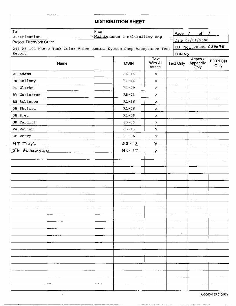
I DISTRIBUTION SHEET
Page I of I To From Distribution Project TitlelWork Order Date oZ/Ol/2000
1241-AZ-101 Waste Tank Color Video Camera System Shop Acceptance Test I EDT N O A ~ Z R U ~ C Z f h q S
Report I ECN No. Attach'' EDTECN
Only
Text Name MSlN With All Text Only Appendix
Attach. Only
I WL Adams I I JR Bellomy R1-56 X
TL Clarke N1-29 X
RV Gutierrez R5-03 X
RS Robinson R1-56 X
IDH Shuford I I DB Smet R1-56 X
GR Tardiff 55-05 X
PA Werner S5-15 X
SM Werry R1-56 X
I I
A-6000-135 (10/97)
I_ - - -. __ - -


![Carnegie, PA 15106-3014 [412] 279-5640 home … 2016/Web...Carnegie, PA 15106-3014 [412] 279-5640 home [412] ... Tom Hyatt, Bill Janiro, Jean Symanko-Andy’s sister, ... ALLELUIA](https://static.fdocuments.us/doc/165x107/5b061dff7f8b9a5c308c870f/carnegie-pa-15106-3014-412-279-5640-home-2016webcarnegie-pa-15106-3014-412.jpg)
