WASTE MANAGEMENT PLAN FOR DRILLING - Celtique · PDF fileWASTE MANAGEMENT PLAN FOR DRILLING...
24
HSEC-BB-PD-04 Waste Management Plan_Drilling Rev 05 This is an uncontrolled copy when printed CELTIQUE ENERGIE BROADFORD BRIDGE – 1 PERMITTING DOCUMENTATION WASTE MANAGEMENT PLAN FOR DRILLING REVISION DATE PREPARED CHECKED APPROVED 01 19/11/2013 J Dobson P Bird 02 26/11/2011 J Dobson P Bird 03 12/12/2013 J Dobson P Bird 04 15/01/2014 J Dobson P Bird 05 30/03/2014 J Dobson P Bird Document Number HSEC-BB-PD-04 Review Date March 2015
Transcript of WASTE MANAGEMENT PLAN FOR DRILLING - Celtique · PDF fileWASTE MANAGEMENT PLAN FOR DRILLING...

HSEC-BB-PD-04 Waste Management Plan_Drilling
Rev 05 This is an uncontrolled copy when printed 1
CELTIQUE ENERGIE
BROADFORD BRIDGE – 1
PERMITTING DOCUMENTATION
WASTE MANAGEMENT PLAN FOR DRILLING
REVISION DATE PREPARED CHECKED APPROVED
01 19/11/2013 J Dobson P Bird
02 26/11/2011 J Dobson P Bird
03 12/12/2013 J Dobson P Bird
04 15/01/2014 J Dobson P Bird
05 30/03/2014 J Dobson P Bird
Document Number HSEC-BB-PD-04
Review Date March 2015

HSEC-BB-PD-04 Waste Management Plan_Drilling
Rev 05 This is an uncontrolled copy when printed 2
Table of Contents Table of Contents ............................................................................................. 2
1 Introduction ................................................................................................ 3
1.1 Background ........................................................................................................ 3
1.2 Referenced Documentation .............................................................................. 3
1.3 Document Structure .......................................................................................... 4
2.1 Overview ....................................................................................................... 5
2.2 Waste Generating Activities......................................................................... 5
3.1 Drilling fluids ............................................................................................... 10
3.2 Drill Cuttings .............................................................................................. 11
3.3 Cement ........................................................................................................ 11
3.4 Natural gas (methane) ............................................................................... 11
4 Fluids & Chemicals .................................................................................. 13
5 Site Operation & Waste Treatment ......................................................... 18
5.1 General ........................................................................................................ 18
5.2 Drilling Fluids .............................................................................................. 18
5.3 Drill cuttings ................................................................................................ 18
5.4 Cement ........................................................................................................ 18
6 Environmental Risk Management ........................................................... 19
6.1 Environmental Risk Assessment ................................................................... 19
6.2 Environmental Risk Mitigation ........................................................................ 19
7 Control & Monitoring................................................................................ 20
7.1 Fugitive Air Emissions ............................................................................... 20
7.2 Mud .............................................................................................................. 20
7.3 Odour ........................................................................................................... 20
7.4 Noise/Vibration ........................................................................................... 20
7.5 Accidents .................................................................................................... 20
7.6 Drilling Muds & Drill Cuttings .................................................................... 21
7.7 Cement ........................................................................................................ 21
7.8 Complaints .................................................................................................. 21
8 Proposed Plan for Closure ...................................................................... 22
9 Measures to Prevent Pollution ................................................................ 24

HSEC-BB-PD-04 Waste Management Plan_Drilling
Rev 05 This is an uncontrolled copy when printed 3
1 Introduction 1.1 Background
Celtique Energie Limited (subsequently referred to as Celtique) intends to construct a boring for the purpose of searching for oil and gas resources at Broadford Bridge. This well is classified as a Non-Inert Mining Waste Operation without a Mining Waste facility. This Waste Management Plan supports Celtique’s permit application for this borehole under Schedule 20 of the Environmental Permitting (England and Wales) Regulations 2010. The purpose of the Plan is to demonstrate that Celtique will manage the wastes which result from its occupation and activities at the site in an environmentally sound manner and that, wherever possible, it uses the waste hierarchy to minimise the potential impact of the operation on its surroundings. The process to drill the well and extract the trapped hydrocarbons will generate extractive waste which falls under the scope of Directive 2006/21/EC (the Mining Waste Directive) and, as a result, an environmental permit is required under Schedule 20 of the Environmental Permitting (England and Wales) Regulations 2010 (as amended). Extractive waste is defined in accordance with Environment Agency Position Statement MWRP PS 015 version 1.0 August 2010. The exploratory drilling site at Broadford Bridge received planning permission from West Sussex County Council (WSCC) in 2012 – permit WSCC/052/12/WC. This Waste Management Plan reflects the agreed conditions from the planning permission and the statutory consultee responses (which included both the Environment Agency and Natural England). Celtique Energie is currently only applying for a Waste Management Permit to cover the drilling of the Broadford Bridge-1 borehole. In the event that potentially economic hydrocarbon reserves are identified, a separate permit application or a variation to this permit will be made to address the testing of this well. Consequently, this Waste Management Plan only covers the drilling of the borehole. The Broadford Bridge-1 borehole is a conventional well and will not, at any stage, involve hydraulic fracturing. The borehole site is situated at:
Broadford Bridge -1 Exploration Site Wood Barn Farm Adversane Lane Broadford Bridge Billingshurst West Sussex
1.2 Referenced Documentation
This Waste Management Plan is part of a suite of documentation submitted by Celtique Energie as part of their permit applications. The full list of documents is as follows:
Summary of Celtique Energie’s HSE Management System (HSEC Management Standards, document number HSEC-MS-001);
Environmental Method Statement (document number HSEC-BB-PD-01);
Environmental Non-Technical Summary (document number HSEC-BB-PD-02);
Site Condition Report and Management & Monitoring Plan (document number HSEC-BB-PD-03);
“Green lined” Site Plan (document number HSEC-BB-PD-05); This document has been written to be as self-contained as possible resulting in some repetition of the information contained in these referenced documents, particularly with regard to the Environmental Method Statement (HSEC-BB-PD-01).

HSEC-BB-PD-04 Waste Management Plan_Drilling
Rev 05 This is an uncontrolled copy when printed 4
1.3 Document Structure
The document is structured as recommended by EPR 6.14 “How to comply with your environmental permit. Additional Guidance for mining waste operations” as follows:
Section 2 defines the Facility Classification;
Section 3 describes the arrangements in place for Waste Prevention & Reduction and the prevention of Environmental Pollution;
Section 4 addresses Fluids & Chemical Additive Information;
Section 5 addresses Site Operation & Waste Treatment;
Section 6 summarises the arrangements in place for Risk Management, addressing both risk assessment and risk mitigation;
Section 7 summarises the arrangements in place for the Control & Monitoring of emissions;
Section 8 summarises the Plan for Closure, addressing the requirements for closure and restoration of the site;
Section 9 summarises the measures in place for the Prevention of Environmental Pollution.
In addition, the following appendices support the Waste Management Plan:
Appendix 1 - Environmental Risk Assessment (ERA): Detailed risk assessment demonstrate that with the application of the controls described in this Waste Management Plan, potential hazards arising from the activities are unlikely to be significant;
Appendix 2 - Hydrogeological Risk Assessment (HRA): Detailed risk assessment which demonstrates that the Broadford Bridge-1 borehole poses no significant risk to controlled waters and that the works do not constitute a groundwater activity.

HSEC-BB-PD-04 Waste Management Plan_Drilling
Rev 05 This is an uncontrolled copy when printed 5
2 Description & Classification
2.1 Overview
The drilling process incorporates a closed loop system whereby drilling fluids (“muds”) are circulated down through the drill pipe and back up the well bore to create hydrostatic pressure (primary well control), return the cuttings created in drilling the well-bore back to the surface and control the temperature of the drill bit. This process is common in other industries including drilling for geo-thermal exploration, water well drilling and drilling within the civil engineering sector. A “waste” is defined in Annex 1 of Article 3(1) of the Mining Waste Directive as any substance or object (in the three categories set out below) which the holder discards or intends to discard or is required to discard. The three categories are:
Inert waste: Waste that does not undergo any significant physical, chemical or biological transformations. Inert waste will not dissolve, burn or otherwise physically or chemically react biodegrade or adversely affect other matter with which it comes into contact in a way likely to give rise to environmental pollution or harm human health. The total leachability and pollutant content of the waste and the ecotoxicity of the leachate must be insignificant, and in particular not endanger the quality of surface water and/or groundwater;
Hazardous Waste: Article 3(2) of the Hazardous Waste Directive lists properties of wastes that render them hazardous. These properties are: explosive, oxidising, highly flammable, flammable, irritant, harmful, toxic, carcinogenic, corrosive, infectious, toxic for reproduction, mutagenic, waste which releases toxic or very toxic gases in contact with water / air / acid, sensitising, ecotoxic, waste capable by any means after disposal of yielding another substance which possesses any of the above characteristics;
Non-Hazardous waste: waste which is neither classified as inert or hazardous waste. The extractive and non-extractive wastes generated in the drilling of the borehole are summarised in Table 2.1 below and described in detail in section 4. Table 2.1: Summary of Extractive Wastes
Waste Type Classification
Non-Hazardous
Water based drilling fluids referred to as Water based muds (WBM)
Hazardous
Oil based drilling fluids referred to as Oil based muds (OBM). Note that only those OBM which cannot be re-used are deemed waste – a small minority of the OBM in use.
Non-Hazardous
Formation cuttings from sections drilled with WBM (cuttings are the broken bits of rock naturally occurring underground and removed from a borehole while drilling into underground formations)
Hazardous
Formation cuttings from sections drilled with OBM
Non-Hazardous
Surplus cement
Hazardous
Natural gas and fluids from the reservoir (if hydrocarbons exist) although these fugitive emissions will be minimal and insufficient to flow, flare or meter.
For greater detail regarding drilling operations the reader is referenced to document HSEC-BB-PD-01 (Environmental Method Statement). However, information relevant to waste management is presented below.
2.2 Waste Generating Activities
2.2.1. - Summary The drilling process is a relatively short duration operation that inherently minimises waste through only using those volumes of raw materials and components that are required to

HSEC-BB-PD-04 Waste Management Plan_Drilling
Rev 05 This is an uncontrolled copy when printed 6
complete the drilling process. Waste prevention and minimisation is further reinforced through the following processes:
Drilling fluids: The volumes required to drill to the target depth are calculated in advance of the drilling operation. The drilling process is monitored by the Drilling Fluids Engineer, and along with the mud logging process this enables monitoring of volumes of fluids pumped downhole and returned to be assessed. The primary considerations when selecting drilling mud is to manage the safety of the well. This aim is impacted by the particular well design, formations and geology to be drilled and achieving the well objectives safely without environmental impact. The general principle followed is that WBM (Water based mud) is used unless its use is not reasonably practicable due to the need to ensure the safety of the well. Geological conditions are also a key factor in preventing reactive clays swelling during the drilling phase causing the drill string to become stuck. Environmentally compatible Oil based mud (OBM) is proposed when reactive claystone sections are expected. Consequently, for Broadford Bridge 1, WBM is used in the drilling of upper part of the well to minimise impact on near surface aquifers. However, once the borehole has been drilled below these aquifers and the interval cased off, it is necessary to use OBM to drill the remainder of the borehole to improve well control in these sections and prevent safety problems arising in the well (the use of WBM in these long sections of water reactive clays and shales can result in drilling problems such as stuck pipe or casing pack-off and potentially increase safety risks). There are also secondary environmental benefits from using OBM in that total drilling time is reduced compared to Water Based Muds – thus resulting in reduced indirect emissions at surface (e.g. reduced use of fuel for the drilling rig or on site generators). In addition, OBM is reusable on subsequent wells whereas WBM is not. The intent is to recycle used WBM during the drilling. Drilling muds with added loss circulation materials are used to prevent loss of drilling fluids into permeable formations. OBM are re-used during the drilling and, once drilling is completed, returned to the supplier for further reconditioning and re- use;
Drill cuttings: Only cuttings from the drilled borehole to the target depth are generated. Reducing-size drill bits are used to reduce hole size and therefore reduce the volumes of returned cutting. Where possible, cuttings solids are recycled into compost/soil improver and eventually for land reclamation/improver;
Cement: Volumes pumped into the well are controlled to minimise returns at surface 2.2.2. – Detailed Description The drilling muds, to be used for this well are both oil and water based as summarised in Table 2.2 below. They are contained in closed loop systems as described below. Detailed information on the chemical make-up of the various muds is given in Section 4 Table 2.2: Drilling Fluids Summary
End Depth MD (ft)
Hole Size (inches)
Drilling Fluid
200 26 Fresh water based
2050 171/2 Water Based Mud system with clay inhibition
6235 121/4 Environmentally Compatible Oil Base Mud System
9784 81/2 Environmentally Compatible Oil Base Mud System
Water based muds (WBM) are used for drilling through fresh water aquifer sections. Any additives used when drilling these sections have all been assessed as non-hazardous substances at the concentrations used (see Hydrogeological Risk Assessment HSEC-BB-PD-06). WBM are treated for re-use during the drilling process site by removal of solids (through the use of shale shakers and centrifuges) and the making up fluid losses. A WBM will produce a volume of cuttings and liquid wastes of around 4 times the volume of the hole to be drilled. As WBM is “used up” in the drilling process, it is sent for waste disposal at the completion of the well

HSEC-BB-PD-04 Waste Management Plan_Drilling
Rev 05 This is an uncontrolled copy when printed 7
Environmentally compatible Oil based muds (OBM) are used to drill the lower sections of the borehole. These muds have been assessed as presenting a hazard “so small as to obviate any present or future damage” (see Hydrogeological Risk Assessment HSEC-BB-PD-06).The OBM is treated for re-use during the drilling process by removal of solids (through the use of shale shakers and centrifuges) and the replenishment of the oil phase. An OBM will produce a waste volume of cuttings and liquid waste of around two to three times the volume of the hole to be drilled. In addition, OBM can always be reused in other wells, they will be returned to the supplier base for cleaning, restocking and reuse. The drilling mud is used to remove drill cuttings from the well and bring them to the surface. These drill cuttings (which are the broken bits of solid rock removed from the borehole) are transported back to surface within the drilling fluids are separated at surface using a two stage process. The first separation stage (shale shakers) vibrates the returned drilling fluid over a screen basket separating large drill cuttings from the drilling muds. The cuttings flow from the shakers via a screen mesh for waste storage in steel rectangular open tanks with a capacity of up to 40m³. If required, further treatment utilising mud cleaners and centrifuges is used to remove finer drill cuttings from the muds. these fine cuttings are also directed to these rectangular open tanks. Drill cuttings are then taken off site for disposal via an authorised waste contractor to an authorised waste facility. Records are maintained on a daily basis of the quantities of drill cuttings from the well bore placed into cuttings skips pending off site removal. Once the cuttings separation is completed, the drilling fluids are then temporarily deposited in dedicated steel mud tanks with a total system volume (active / reserve) of 200m
3.
Where possible, WBM are reused at site for the next hole section (thus reducing the amount of drilling muds required and reducing waste quantities) until the solids entrained become too great for effective treatment. At this point they are replaced by fresh WBM and the “spent” WBM is removed by vacuum loading road tankers to an authorised waste facility. OBM continue to be reused throughout the well and, at completion, are returned to the mud owner (Celtique is simply “renting” use of the fluid) for clean-up and re-use. Double valve isolation is provided on all tanks holding OBM. The returning drilling muds are either reused or sent off site for disposal via an authorised waste carrier to an authorised waste disposal facility. The company looks to minimise waste from these mud systems at all times and this is achieved through good mud management and best drilling practices as well as choosing the appropriate mud systems for the hole to be drilled. Potential loss of drilling fluids into the formation is continuously monitored during drilling by the Mud Logging Unit using a Pit Volume Totaliser (PVT). In the event of a formation loss being identified in the PVT, maintaining borehole stability and controlling fluid leak-off to permeable formations is achieved with the inclusion of fluid loss control additives (lost circulation material – LCM) into the drilling muds. Both the WBM and OBM fluids have a range of additives to adjust their properties and make them suitable for specific hole conditions – these are discussed in detail in Section 4. Once each hole section has been drilled, steel casing is cemented in the wellbore in a series of stages to protect groundwater and maintain wellbore integrity. The cement is pumped in slurry form down the inside of the casing and rises up through the annular space between the drilled hole and the casing, and once in place sets hard. The cemented slurry displaces the mud both from the casing and the borehole to assure continuing well integrity, returning the drilling muds to the surface. The process of replacing the drilling muds with cement slurry is to maintain primary well control, create a complete cement sheath for well integrity and thus provide life of well barriers. After circulating the cement slurry down the well bore and back up the casing annuli a FIT (Formation Integrity Test) is conducted to confirm the integrity of the cement at the casing shoe. The volume of cement used is carefully calculated and pumped volumes are controlled to minimise returns at surface.

HSEC-BB-PD-04 Waste Management Plan_Drilling
Rev 05 This is an uncontrolled copy when printed 8
For the Broadford Bridge -1 well, the 13
3/8”and 9
5/8” casing will be cemented in place. A 8
1/2”
hole is then drilled through the prospective reservoir. If hydrocarbons are found to be present this is cemented in place and a 7” liner installed and perforated for well testing. Figure 2.1 shows a schematic of the borehole.

HSEC-BB-PD-04 Waste Management Plan_Drilling
Rev 05 This is an uncontrolled copy when printed 9
Figure 2.1: Borehole Schematic.

HSEC-BB-PD-04 Waste Management Plan_Drilling
Rev 05 This is an uncontrolled copy when printed 10
3 Waste Prevention & Reduction
The drilling process differs from a manufacturing process in that it is a relatively short duration operation that, in principle, uses only volumes of raw materials and components as needed to complete the drilling. The activities will be conducted so as to prevent waste production wherever possible, and to reduce the quantities generated in all other cases applying the Waste Hierarchy. However, the nature of the operations giving rise to the extractive waste that are the subject of this Plan means that it is practically impossible to de-couple waste creation from the originating process. It is also subject to a degree of variation, and whilst every effort will be made to conserve natural resources and therefore generate as little waste as possible, the precise characteristics encountered in the target reservoir will mean this is subject to change. Prevention and minimisation will be applied as follows:
3.1 Drilling fluids:
Volumes are calculated in advance of the drilling operation - planned drill to target depth. The drilling process is monitored by the Drilling Fluids Engineer, and along with the Pit Volume Totaliser (PVT) and mud logging process this enables monitoring of volumes of fluids pumped and returned. Drilling muds deposit a thin layer of low permeability solids called a filter cake around the sides of the borehole. Loss circulation materials are added to the drilling muds in permeable formations to form a non-permeable layer that prevents any loss of drilling fluids into these formations. The WBM is recirculated and reused until spent. Treatment for re-use consists of removal of solids (through the use of shale shakers and centrifuges) and fluid loss control (replacing lost water). WBM treatment generally becomes uneconomical after a certain amount of use of the mud, at which point the mud become waste. The OBM is treated for re-use during the drilling process by removal of solids (through the use of shale shakers and centrifuges) and the replenishment of the oil phase. Once drilling is completed, this repeat process enables the remaining oil based muds to be returned to the supplier for further conditioning and reuse. Estimated waste quantities, classification and management controls are summarised in Table 3.1 (EWC Classification refers to the European Waste Catalogue) using the following logic:
The drilling fluid used determines the total amount of waste. It is assumed that this results in a total waste volume of 390 m
3 (factor 4 x volume of hole) when using WBM and 364 m
3
(factor 2.5x volume of hole) when using OBM;
The total anticipated volume of drill cuttings is very conservatively estimated to around 373m
3 (based on around 70% greater than the hole volume), comprising approximately
140m3 inert (from WBM drilling) and 233m
3 hazardous (from OBM drilling);
This results in fluid waste volumes of WBM of 250 m3 (390 - 140) and for OBM of 131 m
3
(364 – 233). Table 3.1: Drilling fluids: Estimated waste quantities, classification and controls
Activity Waste Type
EWC 2002 Code
Classification Waste Estimate
(m3)
Management Route
Drill to 2050 ft MD WBM 01 05 04 Non Hazardous 250 Collected and transported offsite for reclamation / treatment
Drill from 2050 ft to target at 9784 ft MD
OBM 01 05 05 Hazardous 131 Transferred offsite for treatment and disposal
HSEC-BB-PD-04 Waste Management Plan_Drilling
Rev 05 This is an uncontrolled copy when printed 11
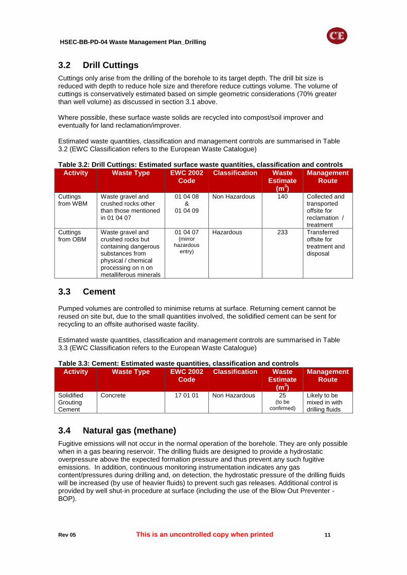
3.2 Drill Cuttings
Cuttings only arise from the drilling of the borehole to its target depth. The drill bit size is reduced with depth to reduce hole size and therefore reduce cuttings volume. The volume of cuttings is conservatively estimated based on simple geometric considerations (70% greater than well volume) as discussed in section 3.1 above. Where possible, these surface waste solids are recycled into compost/soil improver and eventually for land reclamation/improver. Estimated waste quantities, classification and management controls are summarised in Table 3.2 (EWC Classification refers to the European Waste Catalogue) Table 3.2: Drill Cuttings: Estimated surface waste quantities, classification and controls
Activity Waste Type EWC 2002 Code
Classification Waste Estimate
(m3)
Management Route
Cuttings from WBM
Waste gravel and crushed rocks other than those mentioned in 01 04 07
01 04 08 &
01 04 09
Non Hazardous 140 Collected and transported offsite for reclamation / treatment
Cuttings from OBM
Waste gravel and crushed rocks but containing dangerous substances from physical / chemical processing on n on metalliferous minerals
01 04 07 (mirror
hazardous entry)
Hazardous 233 Transferred offsite for treatment and disposal
3.3 Cement Pumped volumes are controlled to minimise returns at surface. Returning cement cannot be reused on site but, due to the small quantities involved, the solidified cement can be sent for recycling to an offsite authorised waste facility. Estimated waste quantities, classification and management controls are summarised in Table 3.3 (EWC Classification refers to the European Waste Catalogue) Table 3.3: Cement: Estimated waste quantities, classification and controls
Activity Waste Type EWC 2002 Code
Classification Waste Estimate
(m3)
Management Route
Solidified Grouting Cement
Concrete 17 01 01 Non Hazardous 25 (to be
confirmed)
Likely to be mixed in with drilling fluids
3.4 Natural gas (methane)
Fugitive emissions will not occur in the normal operation of the borehole. They are only possible when in a gas bearing reservoir. The drilling fluids are designed to provide a hydrostatic overpressure above the expected formation pressure and thus prevent any such fugitive emissions. In addition, continuous monitoring instrumentation indicates any gas content/pressures during drilling and, on detection, the hydrostatic pressure of the drilling fluids will be increased (by use of heavier fluids) to prevent such gas releases. Additional control is provided by well shut-in procedure at surface (including the use of the Blow Out Preventer - BOP).

HSEC-BB-PD-04 Waste Management Plan_Drilling
Rev 05 This is an uncontrolled copy when printed 12
However, in the unlikely event of an unplanned accident scenario when the above controls fail, the drilling rig will shut the well in by closing the annular or BOPs and will vent any such gas arriving at surface into the atmosphere via a diverter line or choke.
HSEC-BB-PD-04 Waste Management Plan_Drilling
Rev 05 This is an uncontrolled copy when printed 13
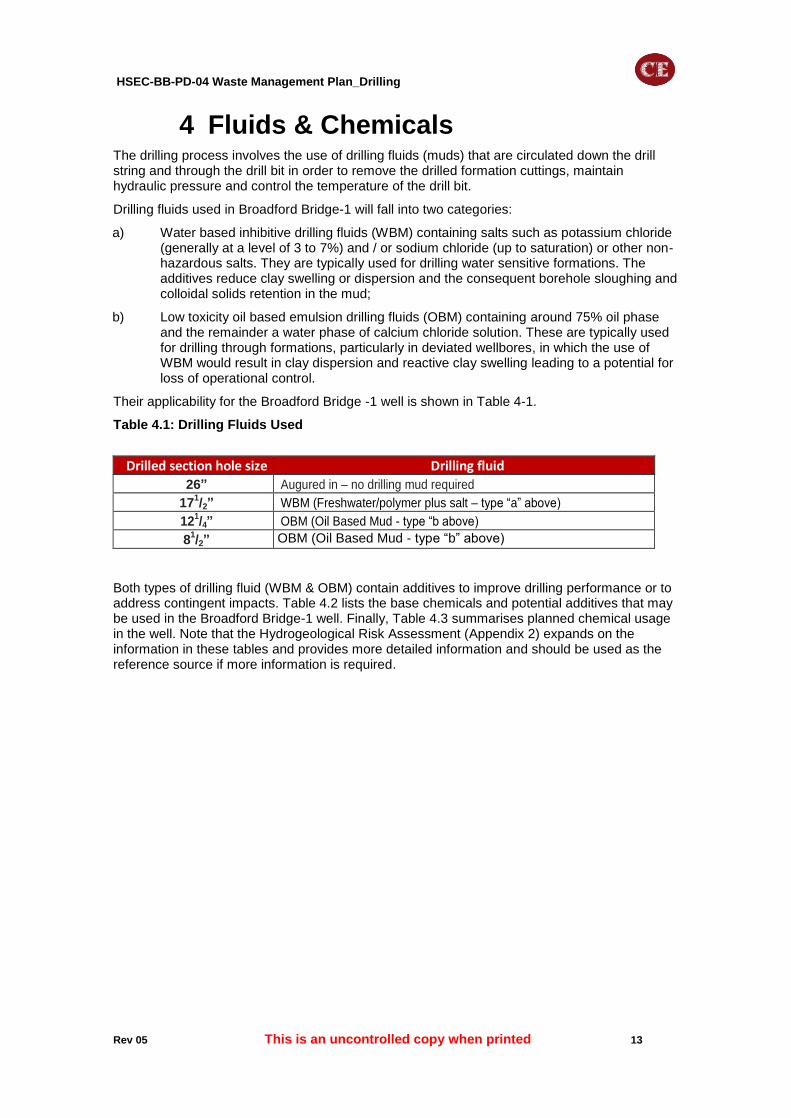
4 Fluids & Chemicals The drilling process involves the use of drilling fluids (muds) that are circulated down the drill string and through the drill bit in order to remove the drilled formation cuttings, maintain hydraulic pressure and control the temperature of the drill bit.
Drilling fluids used in Broadford Bridge-1 will fall into two categories:
a) Water based inhibitive drilling fluids (WBM) containing salts such as potassium chloride (generally at a level of 3 to 7%) and / or sodium chloride (up to saturation) or other non-hazardous salts. They are typically used for drilling water sensitive formations. The additives reduce clay swelling or dispersion and the consequent borehole sloughing and colloidal solids retention in the mud;
b) Low toxicity oil based emulsion drilling fluids (OBM) containing around 75% oil phase and the remainder a water phase of calcium chloride solution. These are typically used for drilling through formations, particularly in deviated wellbores, in which the use of WBM would result in clay dispersion and reactive clay swelling leading to a potential for loss of operational control.
Their applicability for the Broadford Bridge -1 well is shown in Table 4-1.
Table 4.1: Drilling Fluids Used
Drilled section hole size Drilling fluid
26” Augured in – no drilling mud required
171/2” WBM (Freshwater/polymer plus salt – type “a” above)
121/4” OBM (Oil Based Mud - type “b above)
81/2” OBM (Oil Based Mud - type “b” above)
Both types of drilling fluid (WBM & OBM) contain additives to improve drilling performance or to address contingent impacts. Table 4.2 lists the base chemicals and potential additives that may be used in the Broadford Bridge-1 well. Finally, Table 4.3 summarises planned chemical usage in the well. Note that the Hydrogeological Risk Assessment (Appendix 2) expands on the information in these tables and provides more detailed information and should be used as the reference source if more information is required.

HSEC-BB-PD-04 Waste Management Plan_Drilling
Rev 05 This is an uncontrolled copy when printed 14
Table 4.2: Drilling Fluids / Base Chemicals & Potential Additives
Products to be used in drilling mud
Product’s Function
How is the product used?
If the product is only to be used in certain eventualities, explain.
ADAPTA Filtration Control Agent The product is added in a known quantity by the Drilling Fluid Engineer into the fluid at the rig site; the concentration is calculated at the rig site at the time of the addition based on the planned fluid program and monitored properties.
General use: Provides filtration control and secondary viscosity in oil-based muds.
BARACARB Weighting / Bridging Agent
Contingent use: Increases fluid density and it is also used as a bridging agent across porous formations thereby building a filter cake to prevent loss of whole mud or excessive filtrate.
BARACOR 100 Corrosion Inhibitor Contingent use: Helps prevent general corrosion attack on casing, tubing and down-hole tools that could react with dissolved oxygen (O2) to corrode.
BARAKLEAN DUAL Solvent Cleaning Solution Contingent use: Detergent-based casing cleaner typically used to clean the well-bore before running completion equipment into the well.
BARAZAN Suspension Agent/ Viscosifier
Contingent use: Viscosifier for fresh water and brine-based fluids. Suspends solids and weighting materials in fresh water and brine systems.
BARITE Weighting Agent General use: Increases density of drilling muds to control formation pressure and stabilises the well-bore.
BAROFIBRE Lost Circulation Material Contingent use: Helps reduce wall-cake permeability and seepage loss. Wall- cake (mud-cake or filter-cake) is the layer of solid particles formed against the porous formation because of the pressure differential between the hydrostatic pressure in the fluid and the formation pressure. Wall-cake is necessary to isolate the drilling fluid from the formation. Helps seal and bridge depleted sands and micro-fractures.
BAROFIBRE Coarse Lost Circulation Material Contingent use: Helps reduce wall-cake permeability and seepage loss. Wall- cake (mud-cake or filter-cake) is the layer of solid particles formed against the porous formation because of the pressure differential between the hydrostatic pressure in the fluid and the formation pressure. Wall-cake is necessary to isolate the drilling fluid from the formation. Helps seal and bridge depleted sands and micro-fractures.
BAROMUL 303 Oil-Wetting Agent/ Invert
Emulsifier
General use: Stabilises oil-wetting emulsion in oil-based muds. Oil-wetting is a primary property of oil-based muds and indicates the tendency for the well- bore rock to be in contact with an oil-phase rather than a water-phase.
CALCIUM CHLORIDE brine
Shale Stabilizer General use: Brine phase to minimize shale swelling and improve borehole stability.
CALCIUM CHLORIDE powder
Shale Stabilizer General use: Brine phase to minimize shale swelling and improve borehole stability.
CAUSTIC SODA pH Adjuster Contingent use: Used to adjust pH in water-based fluid systems.
CFS-476 Filming Agent Contingent use: Helps prevent general corrosion attack on casing, tubing and down-hole tools that could react with dissolved oxygen (O2) to corrode. Described as a filming agent because it coats the surface of metals and acts as a barrier between the metal surface and the oxygen.
CMO 568 Lubricant Contingent use: Helps reduce torque, drag, and incidence of stuck pipe.
DEXTRID E Filtration Control Agent General use: Used to lower filtration rates in water-based drilling fluids. Helps improve borehole stability and flocculate dispersed drill cuttings to improve cuttings separation from the drilling mud.
EZ MUL NT Oil-Wetting Agent/ Invert
Emulsifier
General use: Stabilises the oil-wetting emulsion in oil-based muds. Oil- wetting is a primary property of oil-based muds and indicates the tendency for the well-bore rock to be in contact with an oil-phase rather than a water- phase.
GELTONE II Viscosifier General use: Viscosifier for oil-based drilling fluids. Required for hole cleaning during drilling and work-over operations. It is used to gel oil drilling fluids for suspension of weighting agents in drilling fluids.
Lime pH Adjuster/ Water
Hardness
Reducer
General use: Used to adjust alkalinity in oil-based muds.
LIQUITONE Filtration Control Agent General use: Provides filtration control and secondary viscosity in oil-based muds.

HSEC-BB-PD-04 Waste Management Plan_Drilling
Rev 05 This is an uncontrolled copy when printed 15
Products to be used in drilling mud
Product’s Function
How is the product used?
If the product is only to be used in certain eventualities, explain.
MICA Lost Circulation Material Contingent use: Helps reduce wall-cake permeability and seepage loss.
OXYGON Oxygen Scavenger/Corrosion
Inhibitor
Contingent use: Oxygen scavenger suitable for mono and divalent brines. Used to inhibit corrosion and maintain the alkaline pH in water-based muds
PAC L Filtration Control Agent General use: Helps control filtration rates without significantly increasing fluid viscosity in water-based muds. In brines, it can be used as a thinner at low concentrations and also as a shale stabilizer by encapsulating the shale to prevent swelling and disintegrations.
SODA ASH Water Hardness Reducer General use: Utilised to reduce drilling mud water hardness, especially where bentonite clay is used as a viscosifier. With excess hardness, the bentonite is inhibited from yielding to perform its function to a sufficient level of effectiveness. Fluid viscosity is essential for the drilling operation.
SODIUM BICARBONATE pH Adjuster Contingent use: Used to adjust pH in water-based fluid systems when contaminated with cement.
STARCIDE Biocide Contingent use: Helps control bacterial contamination in drilling fluids (eg sulphate reducing bacteria) and prevents breakdown of organic colloids.
STEELSEAL 100 Lost Circulation Material Contingent use: Utilized to stop losses in porous and fractured formations in all types of drilling fluids. In water-based fluids, it performs as a solid lubricant for torque and drag reduction. It provides lost circulation treatments for pore plugging as background material and small sized induced and natural fractures. May be used in combination with other lost circulation materials.
STEELSEAL 400 Lost Circulation Material Contingent use: Utilized to stop losses in porous and fractured formations in all types of drilling fluids. In water-based fluids, it performs as a solid lubricant for torque and drag reduction. It provides lost circulation treatments for pore plugging as background material and small sized induced and natural fractures. May be used in combination with other lost circulation materials.
SUSPENTONE Suspension Agent Contingent use: Improves suspension qualities of oil-based muds. Reduces sagging or settling tendencies in deviated or high-angle wellbores.
TOTAL DF1 Base Fluid General use: Low aromatics base oil for oil-based fluids: “C11-C14, n-alkanes, isoalkanes, cyclics, <2% aromatics”.

HSEC-BB-PD-04 Waste Management Plan_Drilling
Rev 05 This is an uncontrolled copy when printed 16
Table 4.1: Planned Chemical Usage
Chemical substance in the products as per the SDSs
CAS number of the component constituent
(1)
WATER-BASED MUD (WBM)
OIL BASED MUD (OBM)
Completion
17 ½ inch drill section
12 ¼ inch drill section
8 ½ inch drill section
Percentage of the substance in drilling
mud (w/w)
Percentage of the substance in drilling
mud (w/w)
Percentage of the substance in drilling
mud (w/w)
Percentage of the substance in
completion fluid (w/w)
PRIMARY CONSTITUENTS
Barium sulfate 7727-43-7 ~28.0 ~28.0 ~28.0 n/a
Calcium chloride 10043-52-4 n/a ~20.0 ~20.0 n/a
Calcium hydroxide 1305-62-0 n/a ~2.0 ~2.0 n/a
Carbohydrate2 - <1.5 n/a n/a n/a
Cellulose derivative: polyanionic cellulose3 - <1.0 n/a n/a n/a
Crystalline silica, quartz 14808-60-7 <1.0 <1.0 <1.0 n/a
Diethylene glycol monobutyl ether 112-34-5 n/a <0.1 <0.1 n/a
Ethylene glycol monobutyl ether 111-76-2 n/a <0.1 <0.1 n/a
Fatty acid, tall-oil, reaction product with diethylenetriamine, maleic, anhydride,
tetraethylenepentamine, and triethylenetriamine
68990-47-6 n/a <1.5 <1.5 n/a
Hydrocarbons, C11-C14, n- alkanes, isoalkanes, cyclics, <2% aromatics
926-141-6*
*EC number
CAS number 64742-47-8
n/a ~48.0 ~48.0 n/a
Hydrotreated light petroleum distillate 64742-47-8 n/a ~1.0 ~1.0 n/a
Polymer in an aqueous emulsion4 - n/a <1.0 <1.0 n/a
Sodium carbonate 497-19-8 <0.1 n/a n/a <0.1
Sodium hydroxide 1310-73-2 <0.1 n/a n/a <0.1
Xanthan gum 11138-66-2 <1.0 n/a n/a <1.0
CONTINGENT CONSTITUENTS
Calcined petroleum coke 64743-05-1 n/a ~6.0 ~6.0 n/a
Calcium carbonate 471-34-1 ~6.0 ~14.0 ~14.0 n/a
Crystalline silica, cristoballite 14464-46-1 n/a ~0.01 ~0.01 n/a
Crystalline silica, quartz 14808-60-7 <0.1 <0.1 <0.1 n/a
Crystalline silica, tridymite 15468-32-3 n/a ~0.01 ~0.01 n/a
Methanol 67-56-1 n/a n/a n/a <0.5
Mica 12001-26-2 <0.5 n/a n/a n/a

HSEC-BB-PD-04 Waste Management Plan_Drilling
Rev 05 This is an uncontrolled copy when printed 17
Chemical substance in the products as per the SDSs
CAS number of the component constituent
(1)
WATER-BASED MUD (WBM)
OIL BASED MUD (OBM)
Completion
17 ½ inch drill section
12 ¼ inch drill section
8 ½ inch drill section
Percentage of the substance in drilling
mud (w/w)
Percentage of the substance in drilling
mud (w/w)
Percentage of the substance in drilling
mud (w/w)
Percentage of the substance in
completion fluid (w/w)
Morpholine process residues 68909-77-3 n/a n/a n/a <0.5
N, N' -Methylene bis (5-methyl oxazolidine) 66204-44-2 n/a n/a n/a <1.0
Nitrilotriacetic acid, trisodium salt monohydrate(5)
5064-31-3 n/a n/a n/a <0.01
Silica gel 112926-00-8 n/a <0.1 <0.1 n/a
Sodium bicarbonate 144-55-8 <1.0 n/a n/a n/a
1. Listed as in SDS and according to the requirements of Regulation (EC) No 1272/2008)

HSEC-BB-PD-04 Waste Management Plan_Drilling
Rev 05 This is an uncontrolled copy when printed 18
5 Site Operation & Waste Treatment 5.1 General
The activities will be conducted so as to prevent waste production wherever practicable, reducing the quantities generated wherever practicable / appropriate. In all cases the Waste Hierarchy will be applied, in order to reduce the amount of material sent to landfill for final disposal, applying recovery / recycling best practice where applicable / appropriate.
However, the nature of the operations giving rise to the extractive wastes which are the subject of this Plan means that it is in essence impossible to de-couple waste creation from the originating process. The drilling process is also subject to a degree of variation, and whilst every effort will be made to conserve natural resources, and therefore generate as little waste as possible, the precise rock / material characteristics encountered in the target reservoir will mean this is subject to change
5.2 Drilling Fluids
Drilling muds are stored on site in high volume storage tanks, circulated down through the drill bit and returned to surface via enclosed lines. The returned drilling muds are passed through mechanical separation devices (known as “shakers”) which are used to extract solid drill cuttings. Further centrifugal treatment is used to remove finer drill cuttings from the muds. Continual sampling and analysis of the drilling muds monitors solids content within the circulated fluids. Once the drilled solids content of the WBM mud reaches 6 to 10% by volume, it is considered degraded in terms of drilling performance and is pumped to open topped skips for off-site transfer via vacuum loading road tanker. The waste drilling muds will be removed by vacuum loading road tanker to an authorised waste facility. The ultimate end waste management route for drilling muds will be dependent on the material composition and it is anticipated that:
Water based muds will be transferred for disposal;
Oil based muds will be transferred for conditioning, resale and reuse. The mud storage tanks will subject to annual thickness inspections and weekly visual integrity inspections.
5.3 Drill cuttings
Drill cuttings that are separated at the surface from the drilling muds, as described above, are stored in steel rectangular open skips with a capacity of up to 40m³. Skips are covered during storage and for any transportation off site. The rectangular containers are subject to annual thickness inspections and daily visual integrity inspections. The waste is transferred onto trailers and subsequently removed to one of several facilities that are appropriately permitted to receive, keep, store and treat industrial wastes of this nature (or exempt from the requirement to hold a permit) and are typically graded into recycled aggregate. Vacuum loading road tankers will be used for drill cuttings waste with a high liquid content.
The rectangular containers will be subject to annual thickness inspections and daily visual integrity inspections.
5.4 Cement
Returning cement to the surface is temporarily stored into skips before being sent off site to an authorised waste facility. Cement returns are minimised by controlling the volumes put into the well.

HSEC-BB-PD-04 Waste Management Plan_Drilling
Rev 05 This is an uncontrolled copy when printed 19
6 Environmental Risk Management 6.1 Environmental Risk Assessment
An Environmental Risk Assessment has been carried out and is documented in Appendix 1. It is in compliance with the requirements of the Environment Agency horizontal guidance H1 Environmental Risk Assessment for Permits, Version 2.1, December 2011 and EPR6.14 “How to comply with your environmental permit - Additional guidance for: mining waste operations, Version 2, February 2011”. This qualitative assessment has considered noise, traffic movement, fugitive emissions, air emissions, releases to water environment, waste and potential for accidents and incidents as these relate directly to the activities. The assessment concluded that with the implementation of appropriate risk management measures, potential hazards from the activities are unlikely to be significant.
6.2 Environmental Risk Mitigation
The Environmental Risk Assessment of Appendix 1 details the risk control and mitigation measures that Celtique Energie will put in place.
HSEC-BB-PD-04 Waste Management Plan_Drilling
Rev 05 This is an uncontrolled copy when printed 20
7 Control & Monitoring The Environment Risk Assessment demonstrate that due to the nature of the waste to be generated and the proposed risk control and mitigation measures, there will be no significant environmental risk and hence only limited monitoring of selected parameters is proposed as listed below.
The quantity of waste arising each day will be monitored and recorded, along with the quantities despatched off-site for disposal. This data will be used to inform waste prevention and reduction strategies
The results of all such monitoring will be used: to inform changes to the Waste Management Plan, be shared with the Environment Agency and used to inform site closure plans.
7.1 Fugitive Air Emissions
The Environmental Risk Assessment has concluded any quantities are expected to be very minor and deemed to pose a low environmental risk.
7.2 Mud
The site is located on a stone pad overlying an impermeable geotextile membrane, with an established unmade access and egress track to the drilling location. A once daily inspection of the road immediately at the juncture of the site entrance will be performed (and the details recorded) to ensure that any potential mud deposits from road tankers visiting to collect extractive waste does not become a problem. In the unlikely event of any build-up of mud and debris, the area will be cleaned using a sub-contracted road sweeper service.
7.3 Odour
Based on prior experience, the extractive waste that will be generated is not malodorous and nor are any of the associated processes that will be performed.
7.4 Noise/Vibration
Road contractors are required to manage HGV deliveries to avoid weekday peak hours and school finishing times. Road tankers visiting the site to collect extractive waste may be fitted with audible reversing alarms. Noise will be maintained within planning condition levels. The site is not in close proximity to residential properties and the anticipated noise levels during site construction and drilling (as calculated in the Environmental Statement) are not predicted to be problem. In addition, the exploration site is screened by natural features (established woodland) providing an additional sound attenuation.
As defined in the Site Monitoring Plan (HSEC-BB-PD-03), noise monitoring will be undertaken at pre-determined locations around the boundary of the site and close to sensitive receptors throughout construction and drilling activities. If any complaint is received an investigation will be conducted into the causes of the complaint. The findings will as appropriate inform further monitoring and risk control arrangements and may lead to additional mitigation measures. Details of any such complaints and any remedial action taken or planned will be discussed with the Environment Agency.
7.5 Accidents
The environmental risk of an accident is predominantly associated with the potential for spillage of extractive wastes. Given that the site is constructed with a large impermeable geotextile membrane providing spillage containment; that pipework and the associated storage tanks will be inspected daily for leaks and damage; that the waste is non-hazardous; and that the site is not situated in a Source Protection Zone (with no potable water abstraction activities in the site boundary or immediately nearby) the environmental risk assessment has concluded the risk to be low. Nonetheless, it is proposed that nearby surface water features will be sampled and tested to identify the presence of extractive waste contaminants prior to construction starting

HSEC-BB-PD-04 Waste Management Plan_Drilling
Rev 05 This is an uncontrolled copy when printed 21
and at regular intervals during construction and drilling as defined in the Site Monitoring Plan (HSEC-BB-PD-03). . The results of this monitoring will be recorded and will inform the future monitoring for the site closure plan. Details of all accidents, and our response, will be shared with the Environment Agency and other regulators as appropriate.
7.6 Drilling Muds & Drill Cuttings
Appropriate storage capacities will be provided for each mud type once it is to be discarded, i.e. water- and oil-based, and, subject to analysis to confirm otherwise, the former will be handled as a non-hazardous material / waste, the latter as a hazardous material / waste The quantity of waste arising each day will be monitored and recorded, along with the quantities dispatched off site for disposal. This data will be used to inform waste prevention and reduction strategies. Fluid and solid drilling waste are sampled at the first available opportunity when drilling commences for chemical analysis and any other additional waste acceptance criteria that is requested by the offsite authorised waste facility.
7.7 Cement
The quantity of waste arising each day will be monitored and recorded, along with the quantities dispatched off site to an authorised waste facility.
7.8 Complaints
If any complaints are received from stakeholders, including neighbours, they will be recorded, investigated and responded to without delay in accordance with the Company’s existing complaints handling procedures. Complaints will additionally be reported to the Environment Agency, with whom actions to avoid a recurrence will be discussed and agreed
HSEC-BB-PD-04 Waste Management Plan_Drilling
Rev 05 This is an uncontrolled copy when printed 22
8 Proposed Plan for Closure In the event that no hydrocarbons are found in the borehole, the well will be abandoned without any testing. This process will involve the following:
Condition 17 of the planning consent for the site sets out the requirements for closure and restoration of the site (ref WSCC/052/12/WC of 11
th February 2013), namely “A scheme of
aftercare specifying the steps to be taken to manage restored land shall be submitted for the written approval of the County Planning Authority prior to the commencement of restoration. Thereafter the approved strategy shall be implemented in full”. This will be complied with;
The well will be plugged and abandoned following industry best practice and regulatory requirements as set out in guidance by:
o Borehole Sites & Operations Regulations 1995 (BSOR);
o Land based requirements of the Offshore Installations and Wells (Design & Construction, etc.) Regulations 1996 (DCR);
o Oil & Gas UK Guidelines for the Suspension & Abandonment of Wells, July 2012
o UK Onshore Operators Group Guidelines.
These approaches will be reviewed and endorsed by both an independent well examiner and the regulator (HSE - Health and Safety Executive);
The process to plug and abandon the well will involve: pumping cement into the well to create a series of plugs and the removal of the wellhead, cutting the casings and sealing them below ground level. No active pollution control requirements will be deployed.
When the well is plugged and abandoned, a closure plan will be developed, agreed with the WSCC, EA and the site owner and implemented as discussed above and the Waste Management Permit will be surrendered. During the period prior to surrender of the permit, as required by the Environment Agency’s guidance “How to comply with your environmental permit. Additional guidance for: mining waste operations”, the following actions will be implemented:
o Any environmental management and monitoring systems (as defined in the Site Monitoring Plan (HSEC-BB-PD-03)) will be maintained and operated until the point of surrender;
o Any aftercare requirements necessary to satisfy other regulatory regimes will be implemented and followed;
o The Environmental Agency will inspect the facility to confirm that all required actions under the permit have been completed.
In the event that the borehole encounters hydrocarbons, the well will be temporarily suspended and the drilling rig released. This temporary suspension will be carried out in compliance with regulatory and industry guidelines to leave the well in a safe state and allow a subsequent test of the reservoir to be made (this test will be the subject of a separate permit application and is not covered by this “drilling” permit documentation). This temporary suspension involves the following actions:
The last well construction operations with the drilling rig will leave the well with a 7 liner cemented in position extending from some 500 ft above the shoe of the 9⅝”" casing to TD;
The well will be filled with inhibited kill weight fluid of sufficient weight (density) to assure that the hydrostatic pressure in the well at the reservoir depth will be in excess of the known reservoir pressure. This combination of cement and fluid provides two independent pressure / isolation barriers between the reservoir and the environment;
In addition, the following actions will be implemented:

HSEC-BB-PD-04 Waste Management Plan_Drilling
Rev 05 This is an uncontrolled copy when printed 23
A kill string comprising of 27/8” tubing) will be run into the well to a depth of around 1000 ft;
A tubing hanger will be landed and a back pressure valve installed into the hanger profile and pressure tested;
All surface valves will be chained closed to prevent any tampering;
The integrity of surface equipment is assured by inspections and maintenance as required;
The security of the surface equipment is provided by security barriers at the well site and security guarding.

HSEC-BB-PD-04 Waste Management Plan_Drilling
Rev 05 This is an uncontrolled copy when printed 24
9 Measures to Prevent Pollution The Environmental Statement for Broadford Bridge-1 and the supporting planning approval and the Risk Assessments to this Waste Management Permit submission (see Appendices) have identified all the potential hazards and pollutant linkages at the site relating to the management of the extractive waste, the risks they pose, and the risk control measures that Celtique will implement in order to mitigate those risks.
These risk control measures are considered to meet the requirements of the Mining Waste Directive, including the need to prevent water status deterioration and soil pollution and are listed below:
Direct discharges of extractive waste: There will be no leachate generated at the site. There will be no deliberate discharges of extractive liquid waste directly to the environment from the site. Measures to prevent the pollution of soil and accidental releases of waste that could cause pollution of surface water and groundwater have been considered and mitigation measures within the environmental risk assessment implemented on site;
Indirect discharges of extractive waste: Mitigation measures are in place to prevent indirect discharges of extractive waste arising from accidents, leaks or percolation into the environment. The mitigation measures are documented with the environmental risk assessment.