Waste Heat Utilization for the Energy Requirements of a ...
14
* NOTE: All content created by the International CCS Knowledge Centre is subject to the Knowledge Centre's Open License. To review the terms of the Open License, click here 15th International Conference on Greenhouse Gas Control Technologies, GHGT-15 15 th - 18 th March 2021 Abu Dhabi, UAE Waste Heat Utilization for the Energy Requirements of a Post Combustion CO 2 Capture Retrofit Study of a Cement Manufacturing Facility Wayuta Srisang a , Stavroula Giannaris a , Corwyn Bruce a , Yuewu Feng a , Dominika Janowczyk a , Brent Jacobs a * a The International CCS Knowledge Centre, 198 – 10 Research Drive, Regina, Saskatchewan Canada S4S 7J7 Abstract This paper presents a preliminary investigation of utilizing waste heat available from a cement manufacturing facility for carbon dioxide (CO2) capture and compression processes. The cement manufacturing facility considered in this study emits 600,000 - 750,000 tonnes of CO2 annually while producing 800,000 – 1,000,000 tonnes of clinker. Determining an alternative energy source for amine regeneration will be a major deliverable and a challenging component of this study. Previously utilized methods from the power industry do not apply in this situation since cement plants do not normally produce steam. Cement manufacturing is an energy intensive process resulting in multiple high temperature exhaust gas streams. In this study, preliminary thermodynamic investigations of the utilization of thermal energy have been performed in two gas streams including kiln flue gas and clinker cooler air exhaust. The scenarios investigated in this study include (1) direct recovery of heat using heat recovery boilers and (2) employing of duct firing to increase the temperature of the flue gas prior to heat recovery. The recovered energy can be used for the amine regeneration process. The use of duct burning subsequently produced excess heat which exceeded the energy need for amine regeneration. However, this option can be utilized to produce medium pressure steam which can then be paired with the installation of a back pressure turbine to produce electricity. The results obtained in this study focused solely on the thermodynamic feasibility and efficiency. To justify whether the proposed strategies are practical or not, several factors including CAPEX and OPEX, requirements for modifications to the existing plant, impacts on the existing cement kiln process, and complexity and reliability of the proposed heat recovery system need to be further considered. Keywords: Waste heat recovery; CCS on cement; Duct firing; CO2 emissions * Corresponding author. Tel.: +1 306 531 2342, E-mail address: [email protected]
Transcript of Waste Heat Utilization for the Energy Requirements of a ...
* NOTE: All content created by the International CCS Knowledge Centre is subject to the Knowledge Centre's Open License.
To review the terms of the Open License, click here
15th International Conference on Greenhouse Gas Control Technologies, GHGT-15
15th - 18th March 2021 Abu Dhabi, UAE
Waste Heat Utilization for the Energy Requirements of a Post
Combustion CO2 Capture Retrofit Study of a Cement
Manufacturing Facility
Wayuta Srisanga, Stavroula Giannarisa, Corwyn Brucea, Yuewu Fenga,
Dominika Janowczyka, Brent Jacobsa*
aThe International CCS Knowledge Centre, 198 – 10 Research Drive, Regina, Saskatchewan Canada S4S 7J7
Abstract
This paper presents a preliminary investigation of utilizing waste heat available from a cement manufacturing facility for
carbon dioxide (CO2) capture and compression processes. The cement manufacturing facility considered in this study emits 600,000
- 750,000 tonnes of CO2 annually while producing 800,000 – 1,000,000 tonnes of clinker. Determining an alternative energy source
for amine regeneration will be a major deliverable and a challenging component of this study. Previously utilized methods from
the power industry do not apply in this situation since cement plants do not normally produce steam. Cement manufacturing is an
energy intensive process resulting in multiple high temperature exhaust gas streams.
In this study, preliminary thermodynamic investigations of the utilization of thermal energy have been performed in two gas
streams including kiln flue gas and clinker cooler air exhaust. The scenarios investigated in this study include (1) direct recovery
of heat using heat recovery boilers and (2) employing of duct firing to increase the temperature of the flue gas prior to heat recovery.
The recovered energy can be used for the amine regeneration process. The use of duct burning subsequently produced excess heat
which exceeded the energy need for amine regeneration. However, this option can be utilized to produce medium pressure steam
which can then be paired with the installation of a back pressure turbine to produce electricity.
The results obtained in this study focused solely on the thermodynamic feasibility and efficiency. To justify whether the
proposed strategies are practical or not, several factors including CAPEX and OPEX, requirements for modifications to the existing
plant, impacts on the existing cement kiln process, and complexity and reliability of the proposed heat recovery system need to be
further considered.
Keywords: Waste heat recovery; CCS on cement; Duct firing; CO2 emissions
* Corresponding author. Tel.: +1 306 531 2342, E-mail address: [email protected]
GHGT-15 Srisang, Giannaris, Bruce, Feng, Janowczyk, Jacobs 2
Nomenclature
CAPEX Capital Expenditures
CCS Carbon Capture and Storage
BOP Balance of Plant
ID Induced Draft
KM CDR Kansai Mitsubishi Carbon Dioxide Removal Process
LP Low Pressure
OPEX Operational Expenditures
WHRU Waste Heat Recovery Unit
1. Project Overview
As the world moves towards decarbonizing more industrial sectors, CCS will play a vital role in reducing the carbon footprints of various industries that do not have renewable alternatives. Cement manufacturing is one such industry as one third of the CO2 emissions results from the chemical conversion of limestone, a key step in the cement manufacturing process that cannot be altered. There are currently no commercial scale CCS facilities in operation on a cement plant. The cement facility considered in this study emits 600,000 - 750,000 tonnes of CO2 annually while producing 800,000 – 1,000,000 tonnes of clinker. The heat recovery investigations described herein are part of the pre-feasibility study work by the International CCS Knowledge Centre, aimed at retrofitting a cement production facility with a full scale, post combustion, amine-based CO2 capture system.
Solvent based post combustion CO2 capture process is the most mature of the CO2 capture technologies. To date,
this technology has been applied to two coal fired power stations, Unit 3 at Boundary Dam Power Station (BD3 ICCS)
in Saskatchewan Canada and the Petra Nova Project in Texas, USA. This process requires energy (in the form of
steam heat) for amine regeneration. The process design of the BD3 ICCS project sourced this required steam from
within the power station’s turbine while an auxiliary heat recovery steam generator was utilized for the Petra Nova
Project. As CCS moves into other industries, sectors that may not have steam at the required regeneration temperatures
and pressures readily available, novel methods for heat recovery and heat integration will have increased importance.
Cement manufacturing is one such industry with a promising future for CCS installations. Cement is used to make
concrete, the second most-consumed material in the world (next to water) and the world’s most consumed man-made
material. With annual global production of cement being more than 4 billion tonnes, the CO2 emitted from cement
production accounts for approximately 8 percent of global CO2 emissions. There are various emission points within the cement facility including the kiln stack, the coal mill stack, and the
clinker cooler stack. The kiln flue gas accounts for most of the emissions and has been identified as the main flue gas stream to be processed.
A key challenge for this study is sourcing the regeneration energy necessary for 90% CO2 capture. As there are
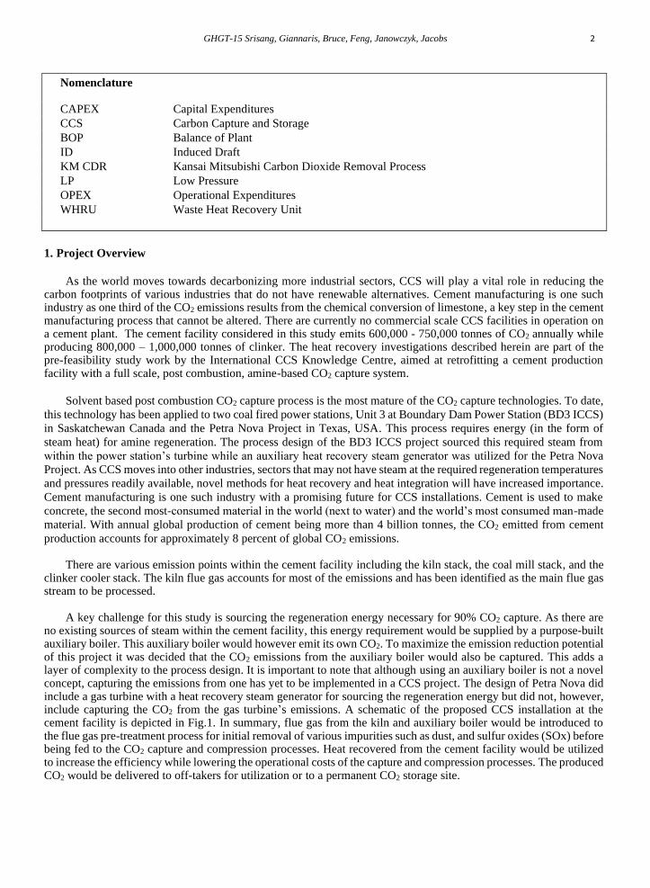
no existing sources of steam within the cement facility, this energy requirement would be supplied by a purpose-built auxiliary boiler. This auxiliary boiler would however emit its own CO2. To maximize the emission reduction potential of this project it was decided that the CO2 emissions from the auxiliary boiler would also be captured. This adds a layer of complexity to the process design. It is important to note that although using an auxiliary boiler is not a novel concept, capturing the emissions from one has yet to be implemented in a CCS project. The design of Petra Nova did include a gas turbine with a heat recovery steam generator for sourcing the regeneration energy but did not, however, include capturing the CO2 from the gas turbine’s emissions. A schematic of the proposed CCS installation at the cement facility is depicted in Fig.1. In summary, flue gas from the kiln and auxiliary boiler would be introduced to the flue gas pre-treatment process for initial removal of various impurities such as dust, and sulfur oxides (SOx) before being fed to the CO2 capture and compression processes. Heat recovered from the cement facility would be utilized to increase the efficiency while lowering the operational costs of the capture and compression processes. The produced CO2 would be delivered to off-takers for utilization or to a permanent CO2 storage site.
GHGT-15 Srisang, Giannaris, Bruce, Feng, Janowczyk, Jacobs 3
Fig. 1. A schematic of the proposed CCS installation at the cement facility
2. Process descriptions and integration of heat recovery
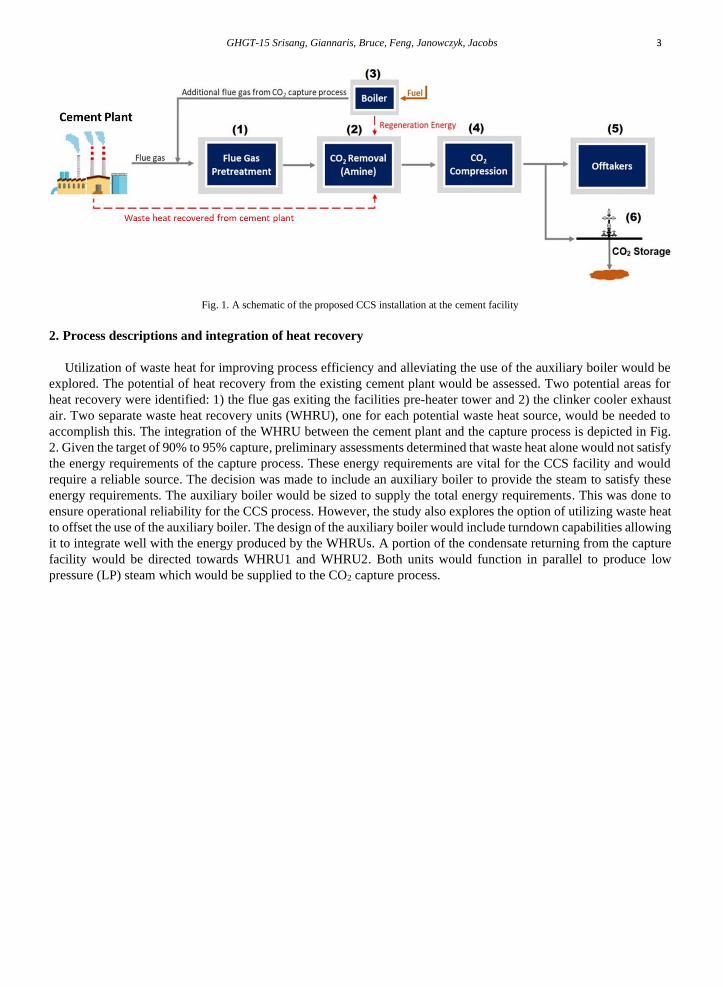
Utilization of waste heat for improving process efficiency and alleviating the use of the auxiliary boiler would be
explored. The potential of heat recovery from the existing cement plant would be assessed. Two potential areas for
heat recovery were identified: 1) the flue gas exiting the facilities pre-heater tower and 2) the clinker cooler exhaust
air. Two separate waste heat recovery units (WHRU), one for each potential waste heat source, would be needed to
accomplish this. The integration of the WHRU between the cement plant and the capture process is depicted in Fig.
2. Given the target of 90% to 95% capture, preliminary assessments determined that waste heat alone would not satisfy
the energy requirements of the capture process. These energy requirements are vital for the CCS facility and would
require a reliable source. The decision was made to include an auxiliary boiler to provide the steam to satisfy these
energy requirements. The auxiliary boiler would be sized to supply the total energy requirements. This was done to
ensure operational reliability for the CCS process. However, the study also explores the option of utilizing waste heat
to offset the use of the auxiliary boiler. The design of the auxiliary boiler would include turndown capabilities allowing
it to integrate well with the energy produced by the WHRUs. A portion of the condensate returning from the capture
facility would be directed towards WHRU1 and WHRU2. Both units would function in parallel to produce low
pressure (LP) steam which would be supplied to the CO2 capture process.
GHGT-15 Srisang, Giannaris, Bruce, Feng, Janowczyk, Jacobs 4
Fig. 2. Schematic of the cement manufacturing plant highlighting two possible locations (WHRU1 and WHRU2) for heat recovery
3. Energy requirements of the CO2 capture process
The CO2 capture process will require energy, primarily for the regeneration of the amine solvent solution within
the stripper column. This energy will be supplied by LP steam fed to the reboilers of the stripper column. The thermal
energy requirement varies depending on the specific amine and process configuration of each vendor. Based on a 90%
capture rate of the CO2 emitted from the kiln, approximately 70 MWth will be required by the CO2 capture process.
This requirement could not be met by using recovered waste heat from within the cement plant alone. An auxiliary
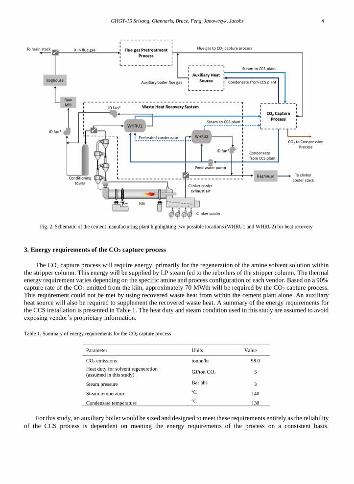
heat source will also be required to supplement the recovered waste heat. A summary of the energy requirements for
the CCS installation is presented in Table 1. The heat duty and steam condition used in this study are assumed to avoid
exposing vendor’s proprietary information.
Table 1. Summary of energy requirements for the CO2 capture process
Parameter Units Value
CO2 emissions tonne/hr 98.0
Heat duty for solvent regeneration (assumed in this study)
GJ/ton CO2 3
Steam pressure Bar abs 3
Steam temperature oC 140
Condensate temperature oC 130
For this study, an auxiliary boiler would be sized and designed to meet these requirements entirely as the reliability
of the CCS process is dependent on meeting the energy requirements of the process on a consistent basis.
GHGT-15 Srisang, Giannaris, Bruce, Feng, Janowczyk, Jacobs 5
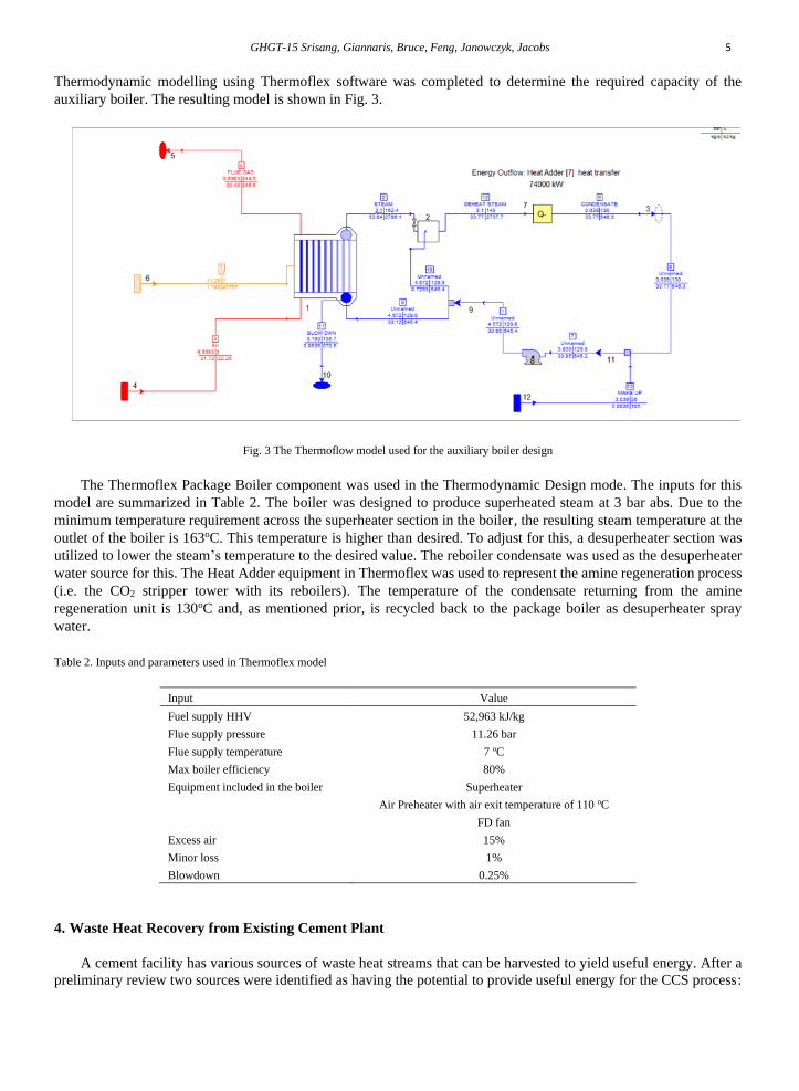
Thermodynamic modelling using Thermoflex software was completed to determine the required capacity of the
auxiliary boiler. The resulting model is shown in Fig. 3.
Fig. 3 The Thermoflow model used for the auxiliary boiler design
The Thermoflex Package Boiler component was used in the Thermodynamic Design mode. The inputs for this
model are summarized in Table 2. The boiler was designed to produce superheated steam at 3 bar abs. Due to the
minimum temperature requirement across the superheater section in the boiler, the resulting steam temperature at the
outlet of the boiler is 163oC. This temperature is higher than desired. To adjust for this, a desuperheater section was
utilized to lower the steam’s temperature to the desired value. The reboiler condensate was used as the desuperheater
water source for this. The Heat Adder equipment in Thermoflex was used to represent the amine regeneration process
(i.e. the CO2 stripper tower with its reboilers). The temperature of the condensate returning from the amine
regeneration unit is 130oC and, as mentioned prior, is recycled back to the package boiler as desuperheater spray
water.
Table 2. Inputs and parameters used in Thermoflex model
Input Value
Fuel supply HHV 52,963 kJ/kg
Flue supply pressure 11.26 bar
Flue supply temperature 7 oC
Max boiler efficiency 80%
Equipment included in the boiler Superheater
Air Preheater with air exit temperature of 110 oC
FD fan
Excess air 15%
Minor loss 1%
Blowdown 0.25%
4. Waste Heat Recovery from Existing Cement Plant
A cement facility has various sources of waste heat streams that can be harvested to yield useful energy. After a
preliminary review two sources were identified as having the potential to provide useful energy for the CCS process:
GHGT-15 Srisang, Giannaris, Bruce, Feng, Janowczyk, Jacobs 6
1) the kiln flue gas stream and 2) the clinker cooler flue gas. Both waste heat sources are available on a continuous
basis. If energy meeting the requirements of the capture process can be recovered from these two sources using
WHRUs the use of the auxiliary boiler could be scaled back. Provided that the installation of the WHRUs is
economical, the ability to turn down the auxiliary boiler could contribute to reduced fuel costs for the auxiliary boiler
and also reduce its CO2 emissions. Properties of these two sources of potential waste heat recovery are summarized
in Table 3.
Table 3. Summary of kiln and clinker cooler flue gas properties
Property Unit Kiln Flue Gas Clinker Cooler Gas
Flow m3/s 218.3 112.9
Temperature °C 400 200
Pressure bar 0.98 0.96
Composition
O2 Mole % 4.88 20.83
CO2 Mole % 16.11 0.03
H2O Mole % 7.90 0.57
N2+Ar Mole % 71.05 78.57
SO2 Mole % 0.06 0
Kiln Flue Gas
Current process operations involve hot gas (~400oC) from downstream of the kiln preheater tower to enter the
kiln conditioning tower to be cooled before it is directed to the raw mill or coal mill. The coal mill does not operate
when the facility uses natural gas as its primary fuel. The hot flue gas enters the top section of this vertical, cylindrical-
shaped tower for cooling, to approximately 200 ˚C, by water injection. The gas is drawn through the conditioning
tower by the kiln ID fan to feed the gas to the raw mill for drying the raw materials and conveying ground mill product
to storage. The gas and raw mill product are then directed to the baghouse for particulate removal. The proposed waste
heat recovery unit (WHRU1), which would recover heat from the flue gas downstream of the preheater tower, is
proposed to be installed in parallel to the existing kiln conditioning tower, as depicted in Fig. 2.
Clinker Cooler Flue Gas
Clinker is cooled from 1200oC to <100oC in a clinker cooler through heat exchange with ambient air. Some of
this heated ambient air is used as combustion air and is fed to the kiln and the pre-calciner. The remaining air, with an
approximate temperature of 200-400oC, is directed through a baghouse to the exhaust duct. The clinker exhaust air is
cooled to approximately 100oC using a heat exchanger before it enters the baghouse for particulate removal. A heat
recovery unit is also proposed to be installed to utilize this heat. The heat recovery unit for clinker cooler exhaust air
(WHRU2) will be installed in parallel with the clinker cooler exhaust air cooler, as depicted in Fig. 2.
The two WHRUs would be installed in a way that would allow the cement plant the ability to operate
independently of the WHRUs, as these could be bypassed when not in operation. As mentioned previously the energy
recovered by the waste heat sources would not satisfy the CO2 capture plants energy requirements. The two WHRUS,
when in service, would work in conjunction with the auxiliary boiler to meet the energy demands of the capture
facility. The additional CO2 emitted by the auxiliary boiler will also be captured resulting in additional energy
requirements for the CO2 capture process. Utilizing available waste heat from the facility helps to overcome this
challenge. Results from the preliminary investigation into sources for the required regeneration energy are summarized
in Fig. 4. This specifically highlights, the relationship between the energy required to capture 90% of the CO2 from
the kiln and the additional CO2 generated due to the amine regeneration energy supply. Results illustrate that the
energy requirement will be significantly lower if the waste heat in the existing conditioning tower and clinker cooler
is recovered and used in the capture process. This justifies investigating waste heat recovery and integration methods
as opposed to sourcing the energy requirement solely from an auxiliary heat source. As heat recovery units and their
installation can add significant costs to a project, an economic impact assessment of this option will be completed.

GHGT-15 Srisang, Giannaris, Bruce, Feng, Janowczyk, Jacobs 7
This will quantify required modifications to the existing plant to accommodate this option such as the installation of
dampers, waste heat recovery systems, additional ID fans, or upgrading the existing ID fan.
Fig. 4. Analysis of energy requirements for a CCS retrofit for the cement manufacturing facility
5. Flue Gas Duct Burner
Duct burning can be used to boost the temperature of the kiln flue gas exiting the preheater tower (upstream of
the conditioning tower) before it enters the WHRU. Although the temperature of this flue gas is enough to operate
directly with the WHRU, duct burning offers increased thermal efficiency, relative to supplementing the heat
requirements with a gas fired auxiliary boiler. This improved efficiency is realized as most of the heat generated by
the duct firing could be utilized to produce steam for the process. In the case of an auxiliary boiler additional flue gas
is generated along with losses in the low grade heat exhausted from the auxiliary boiler.
A duct burning component is intended to be used for heat recovery boilers with supplementary firing. It heats the
incoming flue gases to a desired temperature by burning an appropriate amount of the connected fuel source. The
amount of combustion occurring is usually limited by the amount of available oxygen in the flue gas. A duct burner
can be located in two locations. It can be placed in the transition duct between the source of flue gas and the heat
recovery equipment, or within the main duct after the transition section has expanded the flue gas flow cross section
to the full duct size, in which case the duct burner may be upstream of all of the heat recovery equipment or may be
placed among the heat exchangers.
The impact of using a duct burner to increase flue gas temperature was evaluated. The results of this investigation
are presented here. Duct burning can be done using the flue gas from the kiln as it is or by also adding air to this flue
gas stream to increase the oxygen content and thereby increasing the combustion capacity (and subsequently the
temperature of the emerging flue gas). Two configurations were evaluated:
(1) Flue gas duct firing for low pressure steam generation
(2) Flue gas duct firing for medium pressure steam generation
GHGT-15 Srisang, Giannaris, Bruce, Feng, Janowczyk, Jacobs 8
Modelling these two cases was completed using the Thermoflex software. The Thermodynamic Design mode was
used. The desired exit gas temperature was user specified to allow for sizing of the duct burner component. The inputs
for this modelling are summarized in Table 4.
Table 4. Summary of parameters and inputs utilized in Thermoflex modelling of flue gas duct burning
Parameter/InputProperty Unit Value
User specified flue gas exit temperature oC 800
Heat loss to surroundings as % of heat input % 0.1
Draft loss millibar 0.63
Minimum allowed volumetric oxygen content % 1
Minimum required fuel supply pressure bar 1.72
SO2 to SO3 conversion % 0
Typical element Horizontal HRSG
Fuel flow priority Strong
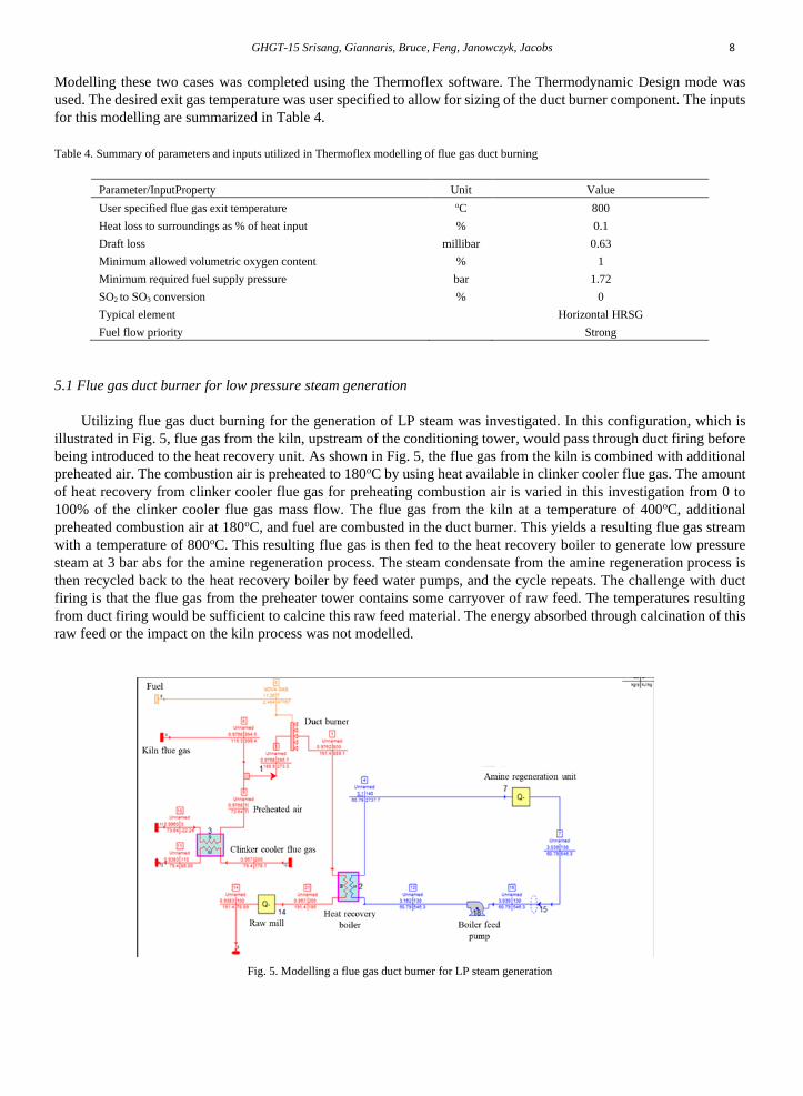
5.1 Flue gas duct burner for low pressure steam generation
Utilizing flue gas duct burning for the generation of LP steam was investigated. In this configuration, which is
illustrated in Fig. 5, flue gas from the kiln, upstream of the conditioning tower, would pass through duct firing before
being introduced to the heat recovery unit. As shown in Fig. 5, the flue gas from the kiln is combined with additional
preheated air. The combustion air is preheated to 180oC by using heat available in clinker cooler flue gas. The amount
of heat recovery from clinker cooler flue gas for preheating combustion air is varied in this investigation from 0 to
100% of the clinker cooler flue gas mass flow. The flue gas from the kiln at a temperature of 400oC, additional
preheated combustion air at 180oC, and fuel are combusted in the duct burner. This yields a resulting flue gas stream
with a temperature of 800oC. This resulting flue gas is then fed to the heat recovery boiler to generate low pressure
steam at 3 bar abs for the amine regeneration process. The steam condensate from the amine regeneration process is
then recycled back to the heat recovery boiler by feed water pumps, and the cycle repeats. The challenge with duct
firing is that the flue gas from the preheater tower contains some carryover of raw feed. The temperatures resulting
from duct firing would be sufficient to calcine this raw feed material. The energy absorbed through calcination of this
raw feed or the impact on the kiln process was not modelled.
Fig. 5. Modelling a flue gas duct burner for LP steam generation
GHGT-15 Srisang, Giannaris, Bruce, Feng, Janowczyk, Jacobs 9
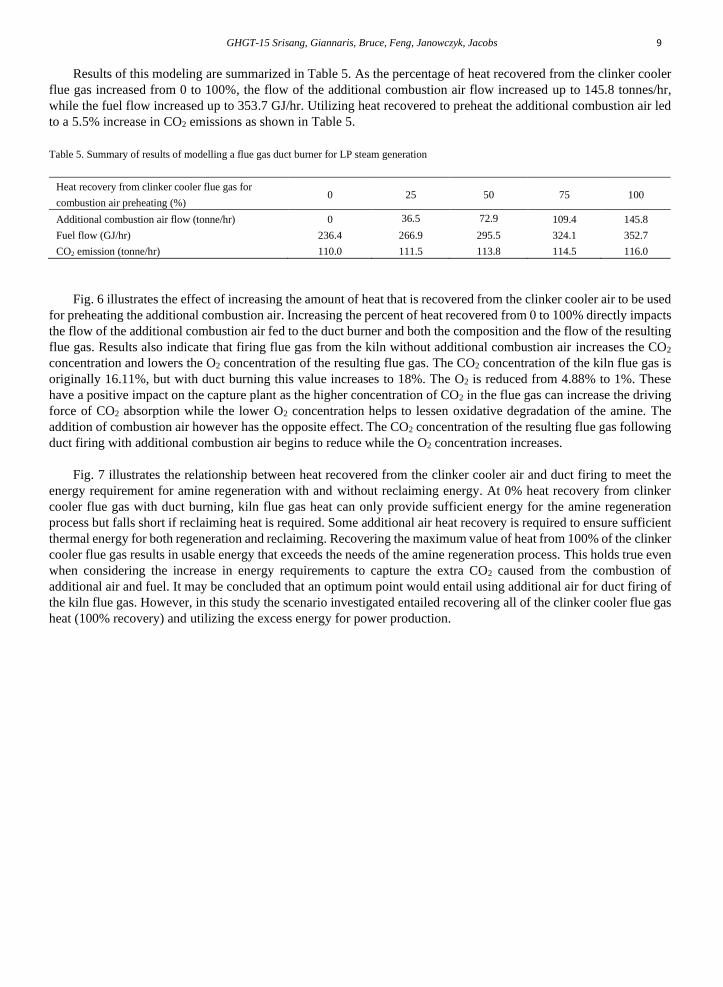
Results of this modeling are summarized in Table 5. As the percentage of heat recovered from the clinker cooler
flue gas increased from 0 to 100%, the flow of the additional combustion air flow increased up to 145.8 tonnes/hr,
while the fuel flow increased up to 353.7 GJ/hr. Utilizing heat recovered to preheat the additional combustion air led
to a 5.5% increase in CO2 emissions as shown in Table 5.
Table 5. Summary of results of modelling a flue gas duct burner for LP steam generation
Heat recovery from clinker cooler flue gas for
combustion air preheating (%) 0 25 50 75 100
Additional combustion air flow (tonne/hr) 0 36.5 72.9 109.4 145.8
Fuel flow (GJ/hr) 236.4 266.9 295.5 324.1 352.7
CO2 emission (tonne/hr) 110.0 111.5 113.8 114.5 116.0
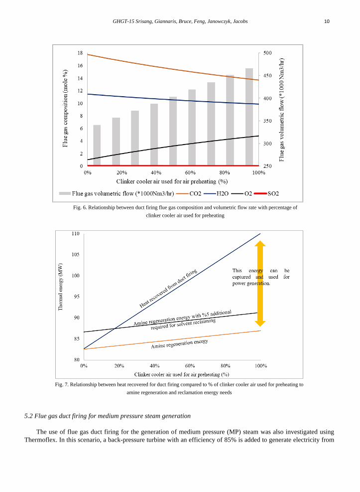
Fig. 6 illustrates the effect of increasing the amount of heat that is recovered from the clinker cooler air to be used
for preheating the additional combustion air. Increasing the percent of heat recovered from 0 to 100% directly impacts
the flow of the additional combustion air fed to the duct burner and both the composition and the flow of the resulting
flue gas. Results also indicate that firing flue gas from the kiln without additional combustion air increases the CO2
concentration and lowers the O2 concentration of the resulting flue gas. The CO2 concentration of the kiln flue gas is
originally 16.11%, but with duct burning this value increases to 18%. The O2 is reduced from 4.88% to 1%. These
have a positive impact on the capture plant as the higher concentration of CO2 in the flue gas can increase the driving
force of CO2 absorption while the lower O2 concentration helps to lessen oxidative degradation of the amine. The
addition of combustion air however has the opposite effect. The CO2 concentration of the resulting flue gas following
duct firing with additional combustion air begins to reduce while the O2 concentration increases.
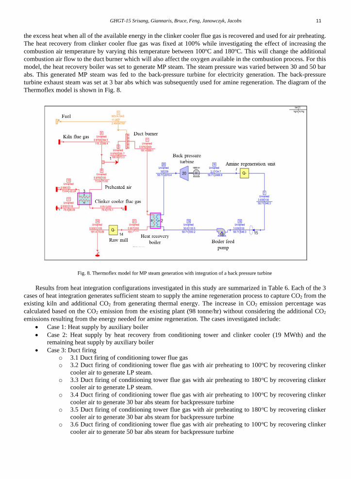
Fig. 7 illustrates the relationship between heat recovered from the clinker cooler air and duct firing to meet the
energy requirement for amine regeneration with and without reclaiming energy. At 0% heat recovery from clinker
cooler flue gas with duct burning, kiln flue gas heat can only provide sufficient energy for the amine regeneration
process but falls short if reclaiming heat is required. Some additional air heat recovery is required to ensure sufficient
thermal energy for both regeneration and reclaiming. Recovering the maximum value of heat from 100% of the clinker
cooler flue gas results in usable energy that exceeds the needs of the amine regeneration process. This holds true even
when considering the increase in energy requirements to capture the extra CO2 caused from the combustion of
additional air and fuel. It may be concluded that an optimum point would entail using additional air for duct firing of
the kiln flue gas. However, in this study the scenario investigated entailed recovering all of the clinker cooler flue gas
heat (100% recovery) and utilizing the excess energy for power production.
GHGT-15 Srisang, Giannaris, Bruce, Feng, Janowczyk, Jacobs 10
Fig. 6. Relationship between duct firing flue gas composition and volumetric flow rate with percentage of
clinker cooler air used for preheating
Fig. 7. Relationship between heat recovered for duct firing compared to % of clinker cooler air used for preheating to
amine regeneration and reclamation energy needs
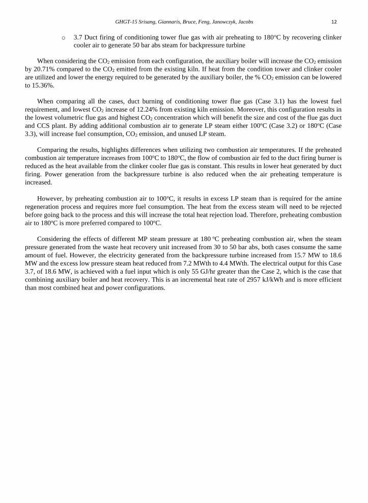
5.2 Flue gas duct firing for medium pressure steam generation
The use of flue gas duct firing for the generation of medium pressure (MP) steam was also investigated using
Thermoflex. In this scenario, a back-pressure turbine with an efficiency of 85% is added to generate electricity from
GHGT-15 Srisang, Giannaris, Bruce, Feng, Janowczyk, Jacobs 11
the excess heat when all of the available energy in the clinker cooler flue gas is recovered and used for air preheating.
The heat recovery from clinker cooler flue gas was fixed at 100% while investigating the effect of increasing the
combustion air temperature by varying this temperature between 100oC and 180oC. This will change the additional
combustion air flow to the duct burner which will also affect the oxygen available in the combustion process. For this
model, the heat recovery boiler was set to generate MP steam. The steam pressure was varied between 30 and 50 bar
abs. This generated MP steam was fed to the back-pressure turbine for electricity generation. The back-pressure
turbine exhaust steam was set at 3 bar abs which was subsequently used for amine regeneration. The diagram of the
Thermoflex model is shown in Fig. 8.
Fig. 8. Thermoflex model for MP steam generation with integration of a back pressure turbine
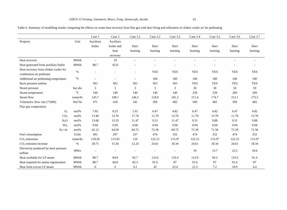
Results from heat integration configurations investigated in this study are summarized in Table 6. Each of the 3
cases of heat integration generates sufficient steam to supply the amine regeneration process to capture CO2 from the
existing kiln and additional CO2 from generating thermal energy. The increase in CO2 emission percentage was
calculated based on the CO2 emission from the existing plant (98 tonne/hr) without considering the additional CO2
emissions resulting from the energy needed for amine regeneration. The cases investigated include:
• Case 1: Heat supply by auxiliary boiler
• Case 2: Heat supply by heat recovery from conditioning tower and clinker cooler (19 MWth) and the
remaining heat supply by auxiliary boiler
• Case 3: Duct firing
o 3.1 Duct firing of conditioning tower flue gas
o 3.2 Duct firing of conditioning tower flue gas with air preheating to 100oC by recovering clinker
cooler air to generate LP steam.
o 3.3 Duct firing of conditioning tower flue gas with air preheating to 180oC by recovering clinker
cooler air to generate LP steam.
o 3.4 Duct firing of conditioning tower flue gas with air preheating to 100oC by recovering clinker
cooler air to generate 30 bar abs steam for backpressure turbine
o 3.5 Duct firing of conditioning tower flue gas with air preheating to 180oC by recovering clinker
cooler air to generate 30 bar abs steam for backpressure turbine
o 3.6 Duct firing of conditioning tower flue gas with air preheating to 100oC by recovering clinker
cooler air to generate 50 bar abs steam for backpressure turbine
GHGT-15 Srisang, Giannaris, Bruce, Feng, Janowczyk, Jacobs 12
o 3.7 Duct firing of conditioning tower flue gas with air preheating to 180oC by recovering clinker
cooler air to generate 50 bar abs steam for backpressure turbine
When considering the CO2 emission from each configuration, the auxiliary boiler will increase the CO2 emission
by 20.71% compared to the CO2 emitted from the existing kiln. If heat from the condition tower and clinker cooler
are utilized and lower the energy required to be generated by the auxiliary boiler, the % CO2 emission can be lowered
to 15.36%.
When comparing all the cases, duct burning of conditioning tower flue gas (Case 3.1) has the lowest fuel
requirement, and lowest CO2 increase of 12.24% from existing kiln emission. Moreover, this configuration results in
the lowest volumetric flue gas and highest CO2 concentration which will benefit the size and cost of the flue gas duct
and CCS plant. By adding additional combustion air to generate LP steam either 100oC (Case 3.2) or 180oC (Case
3.3), will increase fuel consumption, CO2 emission, and unused LP steam.
Comparing the results, highlights differences when utilizing two combustion air temperatures. If the preheated
combustion air temperature increases from 100oC to 180oC, the flow of combustion air fed to the duct firing burner is
reduced as the heat available from the clinker cooler flue gas is constant. This results in lower heat generated by duct
firing. Power generation from the backpressure turbine is also reduced when the air preheating temperature is
increased.
However, by preheating combustion air to 100oC, it results in excess LP steam than is required for the amine
regeneration process and requires more fuel consumption. The heat from the excess steam will need to be rejected
before going back to the process and this will increase the total heat rejection load. Therefore, preheating combustion
air to 180oC is more preferred compared to 100oC.
Considering the effects of different MP steam pressure at 180 oC preheating combustion air, when the steam
pressure generated from the waste heat recovery unit increased from 30 to 50 bar abs, both cases consume the same
amount of fuel. However, the electricity generated from the backpressure turbine increased from 15.7 MW to 18.6
MW and the excess low pressure steam heat reduced from 7.2 MWth to 4.4 MWth. The electrical output for this Case
3.7, of 18.6 MW, is achieved with a fuel input which is only 55 GJ/hr greater than the Case 2, which is the case that
combining auxiliary boiler and heat recovery. This is an incremental heat rate of 2957 kJ/kWh and is more efficient
than most combined heat and power configurations.
GHGT-15 Srisang, Giannaris, Bruce, Feng, Janowczyk, Jacobs 13
Table 6. Summary of modelling results comparing the effects on waste heat recovery from flue gas with duct firing and utilization of clinker cooler air for preheating
Case 1 Case 2 Case 3.1 Case 3.2 Case 3.3 Case 3.4 Case 3.5 Case 3.6 Case 3.7
Property Unit Auxiliary
boiler
Auxiliary
boiler and
heat
recovery
Duct
burning
Duct
burning
Duct
burning
Duct
burning
Duct
burning
Duct
burning
Duct
burning
Heat recovery MWth - 19 - - - - - - -
Heat generated from auxiliary boiler MWth 88.7 65.8 - - - - - - -
Heat recovery from clinker cooler for
combustion air preheater % - - - YES YES YES YES YES YES
Additional air preheating temperature oC - - - 100 180 100 180 100 180
Back pressure turbine NO NO NO NO NO YES YES YES YES
Steam pressure bar abs 3 3 3 3 3 30 30 50 50
Steam temperature oC 140 140 140 140 140 239 239 269 269
Steam flow tonne/hr 145.7 108.1 146.2 218.8 181.2 211.4 174.7 212.1 175.3
Volumetric flow rate (*1000) Nm3/hr 471 418 341 569 465 569 465 569 465
Flue gas composition
O2 mol% 7.85 8.25 1.01 6.47 4.82 6.47 4.82 6.47 4.82
CO2 mol% 13.40 13.76 17.74 11.79 13.70 11.79 13.70 11.79 13.70
H2O mol% 13.60 13.35 11.47 9.31 11.47 9.31 9.88 9.31 9.88
SO2 mol% 0.04 0.05 0.06 0.04 0.06 0.04 0.04 0.04 0.04
N2+Ar mol% 65.12 64.59 69.72 72.39 69.72 72.39 71.56 72.39 71.56
Fuel consumption GJ/hr 401 297 237 474 352 474 352 474 352
CO2 emissions tonne/hr 118.29 113.05 110 122.12 115.97 122.12 115.97 122.12 115.97
CO2 emission increase % 20.71 15.36 12.24 24.61 18.34 24.61 18.34 24.61 18.34
Electricity produced by back pressure
turbine MWe - - - - - 19 15.7 22.5 18.6
Heat available for LP steam MWth 88.7 84.8 82.7 133.6 110.4 113.9 94.2 110.5 91.4
Heat required for amine regeneration MWth 88.7 84.8 82.5 91.6 87 91.6 87 91.6 87
Heat from excess LP steam MWth 0 0 0.2 42 23.4 22.3 7.2 18.9 4.4
GHGT-15 Srisang, Giannaris, Bruce, Feng, Janowczyk, Jacobs 14
6. Conclusion
This paper presents a preliminary investigation of waste heat recovery available at a cement facility and how the
recovered heat can be used to satisfy some of the energy requirements of the CO2 capture process. It is evident from
this evaluation that both kiln flue gas and clinker cooling flue gas are sources for meaningful heat recovery. The waste
heat available can be recovered directly by using flue gas heat recovery boilers. The use of duct firing to increase the
temperature of the flue gas prior to heat recovery can also be implemented to increase waste heat recovery yield. The
recovered energy can be used for the amine regeneration process. The use of duct burning can produce quantities of
heat which exceed the energy need for amine regeneration. However, this option can be utilized to produce MP steam
which can then be paired with the installation of a back pressure turbine to produce electricity (to be used in the capture
plant) with the resultant MP steam before it is directed for amine regeneration. The effective heat rate or incremental
heat input to duct firing for electricity generation would be better than most forms of thermal power generation and
equivalent to or even better than a very efficient combined heat and power arrangement.
To justify whether the proposed strategies are feasible or not, several factors will need to be considered:
• optimization between the CAPEX of the heat recovery unit and the OPEX of fuel cost should be
completed.
• the complexity of implementing and integrating heat recovery equipment with the existing facility.
• reliability of the heat integration process.
• potential changes to start up and shut down of the plant when incorporating heat recovery process;
and,
• potential upsets to the existing process due to higher temperatures and calcining of product in the flue
gas stream from the preheater tower.