Washington County Service Authority Standard ... · Washington County Service Authority Standard...
58
Washington County Service Authority Standard Specifications For The Design and Construction Of Sanitary Sewerage Facilities March 13, 2001 DWE·! Virginia Department or Healtb Ortice or Environmental Health Services Division or W05tewater Engifteering 20a. AreaOlToce: .:ilJutb ,Jf21 1' . } o Operation and Maintenance Manual APProV·-ed---- o Sludge Mannement Plan o Ot>trational Pl." Closure Plan 'P' RellOrts o Other: o ConditionaHy Approved o Disapproved
Transcript of Washington County Service Authority Standard ... · Washington County Service Authority Standard...

Washington County Service Authority Standard Specifications
For The Design and Construction
Of Sanitary Sewerage Facilities
March 13, 2001
DWE·! Virginia Department or Healtb
Ortice or Environmental Health Services
Division or W05tewater Engifteering
20a. AreaOlToce: .:ilJutb ,Jf21 DaA~ 1'. } o Operation and Maintenance Manual .~ APProV·-ed----
o Sludge Mannement Plan
o Ot>trational Pl."
~ Closure Plan
'P' RellOrts
o Other: 2~'" AreaElIgi~
o ConditionaHy Approved
o Disapproved
Washington County Service Authority. General Sewer Line Specifications 03/13101
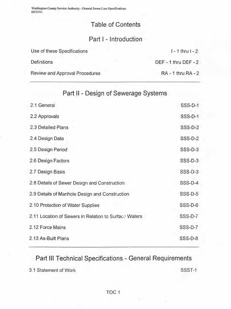
Table of Contents
Part I - Introduction
Use of these Specifications
Definitions
Review and Approval Procedures
1- 1 thru 1-2
DEF - 1 thru DEF - 2
RA - 1 thru RA - 2
Part II - Design of Sewerage Systems
2.1 General SSS-D-1
2.2 Approvals SSS-D-1
2.3 Detailed Plans SSS-D-2
2.4 Design Data SSS-D-2
2.5 Design Period SSS-D-3
2.6 Design Factors SSS-D-3
2.7 Design Basis SSS-D-3
2.8 Details of Sewer Design and Construction SSS-D-4
2.9 Details of Manhole Design and Construction SSS-D-5
2.10 Protection of Water Supplies SSS-D-6
2.11 Location of Sewers in Relation to Surfac,' Waters SSS-D-7
2.12 Force Mains SSS-D-7
2.13 As-Built Plans SSS-D-8
Part III Technical Specifications - General Requirements
3.1 Statement of Work SSST-1
TOC 1
Washington County Service Authority - General Sewer Line Specifications 03/13/01
3.2 Pre-Construction Conference
3.3 Inspection
3.4 Plans, Construction Staking and Cut Sheets
3.5 Safety
3.6 Caution in Excavation
3.7 Approved Plans
3.8 As-Built Plans
3.9 Maintenance Period
3.10 Exceptions
3.11 Pumping Stations
SSST-1
SSST-1
SSST-1
SSST-2
SSST-2
SSST-2
SSST-3
SSST-3
SSST-3
SSST-3
Part IV Technical Specifications - Excavation, Installation, Backfilling and Restoration
4.1 Classification SSSEIB-1
4.2 Clearing SSSEIB-1
4.3 Excavation and Preparation of Trench SSSEIB-1
4.4 Installation of Pipe Fittings and Manholes SSSEIB-3
4.5 Backfilling SSSEIB-9
4,6 Restoration SSSEIB-10
4.7 Sewers Crossing Streams, Estuaries, Lakes and Reservoirs SSSEIB-11
4.8 Boring, Jacking and Tunneling SSSEIB-12
Part V Technical Specifications - Materials
5.1 Pipe SSSM-1
TOC2
Washington County Service Authority - General Sewer Line Specifications 03/13101
5.2 Manholes
5.3 Manhole Connections
5.4 Manhole Frames and Covers
5.5 Manhole Inverts
5.6 Grout
5.7 Cleanouts
5.8 Steel Casing Pipe
5.9Insta"ation
5.10 Bedding and Backfi"
Section VI - Standard Details
SSSM-2
SSSM-3
SSSM-3
SSSM-4
SSSM-4
SSSM-4
SSSM-4
SSSM-5
SSSM-5
Manhole #1 - Precast - Standard------------------------------------------------SI)1
Manhole #2 - Precast - Use on Existing Lines--------------------------------------SI)2
Manhole #3 - Precast - Drop Manhole----------------------------------------------SI)3
Standard Manhole Cover and Frame-------------------------------------------------SI)4
Watertight Manhole Cover & Frame--------------------------------------------------SI)5
Standard Manhole Step--------------------------------------------------------------SC6
Standard Service Connection---------------------------------------------------SI)7
Standard Clean-out --------------------------------------------------------------S1)8 Concrete Encasement for Sewer Line---------------------- -- ----------------~
Concrete Anchor Detail------------------------- ---------------------------------------SD1 0
Road Crossing Detai 1----------------------------------------,.---------------------SD11
Water and Sewer Separation------------------------------------------------------SD12
Bedding C lass Detail-----------------------------------------------------------S013
TOC3

Washington County Service Authority - General Sewer Line SpecifICations 03113/01
INTRODUCTION
USE OF THESE SPECIFICATIONS
These standard technical specifications are intended to be used for the design and construction of
sanitary sewers to be owned by the Washington County Service Authority 0NCSA). The use of
these specifications in conjunction with engineering plans, which address the specifics of
individual projects, will result in standardized construction of sewer lines in the WCSA sewage
collection system.
These specifications shall be adhered to in the design & construction of all new sanitary sewers of
8, 10, and 12 inch diameter, installed to collect sewage and deliver it to WCSA sewerage systems.
All projects shall be formally approved by WCSA prior to starting construction. The use of these
specifications will facilitate expansion of our existing sewerage systems at minimum cost to the
Owner developing the sewer lines.
WCSA has attempted to organize these specifications in a way that promotes access and
understanding. The Owner, Engineer and Contrau"lr should become very thoroughly familiar with
these specifications prior to use. The specifications are targeted at experienced professionals
who design and install gravity sewer lines. It should also be noted sewer line installation requires
specialized teGhniques of installation such as rock mitigation, and specialized equipment for
insuring proper alignment of the sewer lines during construction.
1-1

Washington County Service Authority - General Sewer Line Specifications 03/13/01
WCSA will not accept the ownership of, or the flow of sewage from improperly construction
sewer lines. While WeSA will have inspector(s) observing the construction of the sewer line, the
ultimate responsibility for proper installation of sewer lines lies with the owner of the project.
These speCifications have been prepared by WeSA and meet or exceed the minimum
requirements of the "Commonwealth of Virginia Sewage Collection and Treatment (SCA T)
Regulations. The technical aspects of these specifications have been approved by the Virginia
Department of Health - Office of Environmental Health Services (OEHS) and the Virginia
Department of Environmental Quality (DEQ) for use by we SA and others (with WCSA approval)
for designing and constructing gravity sewer lines. These specifications shall be used for the
construction of gravity sewer lines whose ultimate ownership will be held by WeSA unless the
use of other specifications are specifically approved by WeSA, OEHS and DEQ.
Finally, WeSA believes that the development of these specifications will significantly streamline
the project review process. This should mean a shorter processing time for approvals of sewer
line projects by WeSA and the regulatory agencies involved. As those who work with these
standards become familiar with them, design time and construction time should also be reduced
resulting in a significant cost savings for all involved.
1-2

WCSA General Sewer line Specifications 03/13/01
DEFINITIONS
Unless the context specifically indicates otherwise, the meaning of terms used in the rules and
regulations shall be as follows:
1 ) Collection System means the mains, laterals, service connections, manholes and pumping
facilities used for the collection of sewage from its source (property line of the owner) to the
Washington County Service Authority CNCSA) sewage treatment facilities or altematively the
Town of Abingdon or City of Bristol, Virginia mains.
2) Customer means any person, firm, corporation, company association, governmental. unit or
owner of property fumished sanitary sewer service by the Washington County Service
Authority.
3) General Manager means the General Manager of the Washington County Service Authority or
his authorized deputy agent or representative.
4) Main means a sewer pipe owned, operated and maintained by WCSA which is used for the
purpose of transmission or collection of sanitary sewage but is not a sewer service lateral.
5) Owner as used herein as it applies to the owner of property which the proposed sewer
extensions will serve. Owner as it applies to applications for sewer services and payments for
treatment shall mean the owner of real property and dwellings or structures thereon, or the
owner of dwellings or structures on leased land.
6) Premises as used herein shall include but is not restricted to the following:
a) A building or combination of buildings owned by one family as a residence.
b) Each unit of multiple building separated by a solid vertical partition wall owned as a
residence or owned or leased by one firm as a place of business.
c) A building owned by one customer and having a number of apartments, offices or lofts
using in common one hall and one or !"'lore means of entrance.
d) A building two or more stories high under one roof owned by one customer and having an
individual entrance for the ground floor occupants and one for the occupants of the upper
floor.
e) A combination of buildings owned by one customer, in one common enclosure, none of the
buildings of which is adapted to separate ownership.
f) A public building.
g) A single plat used as a park or recreational area.
DEF -1
WCSA General Sewer line Specifications 03113/01
7) Property Line shall mean the edge or limit of the street, highway, public way, or right-of-way as
may be shown or platted on maps of record before entering on private property of the
premises.
8) Service Lateral shall mean the pipe that runs between the main and the customer's property
line or utility easement. That portion from the main to the property line is the City's service
a) lateral; that portion from the property line to the premises is the owner's service lateral.
9) County shall mean Washington County, Virginia.
10) WCSA shall mean the Washington County Service Authority.
11) Equivalent Residential Unit For the purposes of establishing connection fees an Equivale~t
Residential Unit is defined as the average consumption of 5000 gallons of water per month. A
single family dwelling unit shall be considered one equivalent unit. When computing the
"equivalent" of buildings or structures other than dwelling units, the average water consumption
rate of 5000 gallons per month day shall be used as the basis for determining the equivalency.
For the purposes of design, the design basis required by these specifications shall be an
average daily water use of 400 gallons per residential unit in accordance with the regulations
of the Virginia Department of Health prevailing at the time. Deviation from this design basis
will be considered on a case by case basis upon written request by the Owner or his
designated agent. Approval for an alternate design basis will be made in writing by WCSA
after consultation with the Virginia Department of Health and or Department of Environmental
Quality.
12) Shall means a mandatory requirement. Plans not conforming to criteria or limits introduced by
"shall" may be approved by the Utility when submitted with adequate justification.
13) Should means a recommendation. However, WCSA reserves the right to change a
recommendation to a requirement when in the opinion of WCSA, it is appropriate to do so from
a public health standpOint or when it is in the best interest of WCSA .
14) May generally means an item left to tr2 discretion of the owner or his designated agent.
However, WCSA reserves the right to change a recommendation to a requirement when in the
opinion of WCSA, it is appropriate to do so from a public health standpoint or when it is in the
best interest of WCSA .
DEF-2

Washington County Service Authority - General Sewer Line Specifications 03/13/01
Review and Approval
Review and approval of plans and design notes for all sewerage facilities shall be submitted to and
approved by the following agencies prior to construction:
1) The Virginia Department of Health - Office of Environmental Health Services
2) Virginia Department of Environmental Quality (unless a waiver for formal approval for the
proposed project is granted by those agencies.)
3) The Washington County Service Authority CNCSA
Processing of Plans and Design Notes
These General Specifications cover many aspects of sewer line design and construction.
Specifically the following sections of the Sewage Collection and Treatment Regulations (SCAT)
are covered by the WCSA Standard Specifications (The numbers in bold refer to the same
numbered section in the SCAT regulations.)
i) 12 VAC 5-581-390 Construction Details
(1) Minimum Size
(2) Pipe Joints and Infiltration
(3) Building Sewers and connections
(4) Leakage Testing
(5) Trench Construction and Pipe Bedding
(6) Backfill and Tamping
ii) 12 VAC 5-581-410 Manholes
(1) Materials
(2) Measurements
(3) Foundations
(4) Flow Channel
(5) Watertightness
(6) Connections
(7) Frames, Covers and Steps
(8) Drop Pipe (Standard Detail Only)
iii) 12 VAC 5-581-420 Water Quality and Public Health Protection
(1) Design Integrity
(2) Water Supply Interconnections
RA-}

Washington County Service Authority· General Sewer Line Specifications 03113/01
Project Specific Data Required to be submitted with each proposed project includes the
following.
iv) 12 VAC 5-581-370 Design Factors
(1) Basis
(2) Factors
(3) Capacity
v) 12 VAC 5-581-380 Design Details
(1) Collection Lines
(a) Depth
(b) Slope
(c) Alignment
(d) Increasing Size
(e) High Velocity Protection
(f) Property Access
(2) Manholes
(a) Location
(b) Ventilation
(c) Drop Pipes - if needed
(3) Special considerations for Sewers and Manholes in Relation to Streams, Estuaries,
Lakes, Reservoirs
(4) Special considerations for Relationship to Water Works Structures
Materials Approval - These general specifications are very specific with respect to the materials
which are acceptable for sanitary sewer lines and associated appurtenances. To that end:
vi) Only materials and equipment allowed by these specifications or approved specifically
in writing by the WCSA Utilities shall be utilized in sewerage facilities .
vii) Deviations - There shall be no deviations from the standard specifications except in
unusual circumstances. All deviation requests must be submitted to WCSA in writing for
the review and approval prior to construction.
RA-2

Washington County Service Authority - General Sewer Line Specifications 03/13/01
PART II
SANITARY SEWER SPECIFICATIONS
DESIGN OF SEWERAGE SYSTEMS
2.1 General: Plans and speCifications for sanitary sewer systems shall be prepared by or under the
supervision of a registered professional engineer who shall affix his seal to each
plan-profile sheet, accompanying sheets showing details, and to the specifications. A
land surveyor who has passed Part 3 (b) of the Land Surveyor's exam given by the BOoil G
for the Examination and Certification of Architects, Professional Engineers and Land
Surveyors may, for subdivisions only, prepare plans and profiles for sanitary sewer
extensions where such work involves the use and application of standards prescribed by
local or state authorities.
2.2 Approvals:
Two sets of plans and design notes shall be submitted to the General Manager of WCSA
for each sewerage project. The plans and design notes will be reviewed and one set
returned to the design professional with recommended changes and/or approval. Four sets
of plans, specifications and design data shall be submitted concurrently to the Virginia
Department of Health Department (VDH) for review and/or approval. If appropriate,
WCSA will support a request from the owner to VDH for waiver of formal review and
approval by that agency. WCSA will consider such a request if the proposed sewer line
will serve less than 400 persons or less, consists entirely of gravity slow sewers, is not
technically challenging with respect to design or construction and when adequate capacity
of downstream facilities sewers is not an issue. After all changes required by VDH and
WCSA have been made, (4) sets 01 plans bearing the appropriate seal shall besubmiUed
to the Health Department for final approval. If appropriate WCSA will inform VDH of its'
intention to accept the wastewater from and the ownership of the sewer lines after
successful construction
SSS-D-1

Washington County S~vice Authority. General Sewer Line Specifications 03/13/01
2.3 Detailed Plans:
Detail plans shall be submitted on 24" x 36" plan-profile sheets. Profiles should have a
horizontal scale of not more than 100 feet to the inch and a vertical scale of not more
than 1 0 feet to the inch. A horizontal scale of 1" = 50' shall be preferred. Plan view should
be drawn to a corresponding horizontal scale. Plans and profiles shall show:
d) Location of streets and sewers. Show recorded lots and other property lines. Show names
of property owners when appropriate.
e) Permanent elevation benchmarks shall be set on NGS datum at approximately 1000 feet
intervals. These benchmarks shall be shown graphically on the plan with the des'- '; oticn
and elevations shown on the profile.
f) Line of ground surface and proposed ground surface, size, material, and type of pipe,
length between manholes, invert and surface elevation on NGS datum at each manhole,
and grade of sewer between each two adjacent manholes. All manholes shall be numbered
on the plan and correspondingly numbered on the profile. Where there is any question of
the sewer being sufficiently deep to serve any residence, the elevation and location of the
basement floor shall be plotted on the profile of the sewer which is to serve the house in
question.
g) Locations of all special features such as inverted siphons, concrete encasements,
elevated sewers, etc.
h) All known existing structures both above and below ground which might interfere with the
proposed construction particularly water mains, gas mains, storm drains, etc.
i) Special detail drawings, made to scale to clearly show the nature of the design, shall be
furnished to show the following particulars:
i) All stream crossings, with elevations of the stream bed and water levels.
ii) Details of all special sewer joints and cross sections
iii) Details of all sewer app,,1enances not shown on the standard detail sheet.
j) A statement that sewer lines shall be installed in accordance with WCSA General Sewer
Line Specifications.
k) Plans shall have a title block and shall show the owner, the design engineer, and the date
of the drawing and all revision dates.
2.4 - Design Data:
The following information shall be included with submittal of plans and specifications for approval:
SSS-D-2
Washington County Service Authority - G~neral Sewer Line Specifications 03/13/01
a. Map showing area to be served directly and also tributary design population. Show method
of calculation of tributary population.
b. Number of persons to be served directly and estimate of tributary design population. Show
method of calculation of tributary populations.
c. Show any industrial, commercial, or institutional flow contribution with statement as to
probability of increase or decrease of present flow. Indicate maximum or minimum rates of
flow from these contributors and the presence of any flow that would be detrimental to the
sewerage system.
2.5 Design Period:
In general sewer systems should be designed for the estimated ultimate tributary
population, except in considering parts of the systems that can be readily increased in
capacity. Similarly, consideration should be given to land use plans, zoning maps and to
other planning docents and to the maximum anticipated capacity of institutions, industrial
park.s, apartment developments, etc.
2.6 Design Factors:
In determining the required capacities of sanitary sewers, the following factors should be
considered:
a. Maximum hourly sewage flow.
b. Additional maximum sewage or waste flow from industrial plants.
c. Ground water infiltration and extraneous inflow
d. Topography of area.
e. Actual or anticipated zoning.
f. Location of waste treatment plant.
g. Depth of exca.ation.
h. Pumping requirements
2.7 Design Basis:
a. Per Capita Flow: New sewer systems shall be designed on the basis of an average daily
per capita flow of sewage of not less than 100 gallons per day. This figure is assumed to
cover normal infiltration. but an additional allowance should be made where conditions are
unfavorable. Generally. the sewers should be designed to carry when running full. not less
SSS-D-3

Washington County Service Authority· General Sewer Line Specifications 03/13/0 1
than the following daily per capita contributions of sewage, exclusive of sewage or other
waste flow from industrial plants.
i. Laterals and Sub-Main Sewer
1. Lateral- A sewer that has no other common sewers discharging into it,and shall be
installed according to standard Detail Sheet 5.7 and 5:8.
2. Sub-Main - A sewer that receives sewage flow from one or more lateral sewers.
Minimum peak design flow = 400% of average design flow.
ii. Main. Trunk. and Interceptor Sewers:
1. Main or Trunk - A sewer that receives sewage flow from one or more sub-main
sewers.
2. Interceptor - A sewer that receives sewage flow from a number of gravity main or
trunk sewers, sewage force main, etc. Minimum peak design flow = 250% of average
design flow from main, trunk or interceptor.
iii. Alternate Method:
1. When deviations from the foregoing per capita rates are demonstrated, a description
of the procedure used for sewer design shall be included.
2.8 Details of Sewer Design and Construction
a. Minimum Size:
i. No sewer shall be less than eight (8) inches in diameter except that service laterals for
individual house connections and single apartment buildings of 6 units or less shall be a
minimum of 6 inches in diameter. The 6" minimum diameter shall only apply to that
portion of the lateral from the sewer main to the clean out at the property line or
easement boundary.
b. Depth: - In general, sewers shall be sufficiently deep so as to receive sewage from
basements and to prevent freezing. The absolute minimum shall be two (2) feet.
c. Slope: - All sewers shall b 8 so designed and constructed to give mean velocities, when
flowing full, or not less than 2.0 feet per second, based on the Manning equation using an
"n" value of 0.013. Use of other practical "n" values may be permitted if deemed justifiable
on the basis of research or field data presented. The following are the minimum slopes
which should be provided; however, slopes greater than these are desirable:
SSS-O-4

Washington County Service Authority· General Sewer Line Specifications 03/13/01
Sewer Size
6 inch
8 inch
10 inch
12 inch
Minimum slope in feet per 100 Feet
1.0
0.40
0.28
0.22
Sewers shall be laid with uniform slope between manholes. Sewers on 20 per cent slope or
greater shall be anchored securely with concrete anchors or equal, spaced as follows:
a. Not over 36 feet center to center on grades 20 percent and up to 35 percent.
b. Not over 24 feet center to center on grades 35 percent and up to 50 percent.
c. Not over 16 feet center to center on grades 50 percent and over.
d) Alignments: Sewers 24 inches or less shall be laid with straight alignment between
manholes.
e) Increasing Size: When a smaller sewer joins a larger one, the invert of the larger sewer
should be lowered sufficiently to maintain the same energy gradient. An approximate
method for securing these results is to match the crowns of the pipe. Changes in the
diameter of the sewer shall only be accomplished at manholes unless specifically approved
in writing by WCSA.
f) High Velocity Protection: Where velocities greater than 15 feet per second are attainted,
special provision shall be made to protect against displacement by erosion and shock.
g) Materials: Any material permitted by the technical specifications for sewers will be given
consideration, but the material selected should be adapted to local conditions such as
character of industrial wastes, possibility of septicity, soil characteristics, exceptionally
heavy external loadings, abrasion and similar problems. Also the sewer material shall be
kept uniform between sewer manholes, unless otherwise approved in writing by WCSA.
(1) Encasement: All sewers shall be designed to prevent damage from superimposed
loads. Proper allowance for k,;"lds on the sewer shall be made because of the widt,'"
and depth of trench. This may be accomplished by encasement in concrete
(standard detail 5.10) or by placement in an approved conduit.
2.9 Details of Manhole Design and Construction
a) Location: Manholes shall be installed at the end of each line; at all changes in grade, size,
or alignment; at all intersections; and at distances not greater than 400 feet for sewers 15
inches or less and 500 feet for sewers greater than 15 inches. Cleanouts may be used only
SSS-0-5
Washington County Service Authority - General Sewer Line Specifications 03/13/01
for special conditions and shall not be substituted for manholes nor installed at the end of
laterals greater than 150 feet in length. A 20' off- set- hub shall be required at each
manhole.
b) Drop Type: A drop pipe should be provided for a sewer entering a manhole at an elevation
of 24 inches or more above the manhole invert. Where the difference in elevation between
the incoming sewer and the manhole invert is less than 24 inches, the invert should be
filleted to prevent solids deposition. A drop manhole shall also be provided when the there
is less than a 90 degree angle between the entering influent line and the exiting effluent
line.
c) Diameter - The minimum diameter of manholes shall be 48 inches.
d) Elevation drop through manhole - a minimum drop of 0.1 foot shall be provided between
the influent invert elevation and the effluent invert elevation.
2.10 Protection of Water Supplies:
a) Water Supply Interconnections: There shall be no physical connection between public or
private potable water supply system and a sewer, or appurtenance thereto which would
permit the passage of any sewage or polluted water into the potable supply.
b) Relation to Water Works Structures: The horizontal distances from a well to any pipe
carrying sewage or pipe in which sewage can bask up shall be at least 50 feet.
c) Relation to Water Mains:
i) Parallel Installation of Water and Sewer Lines:
(1) Normal Conditions
(a) Whenever possible, sewers and sewer manholes should be laid at least 10 feet,
horizontally, from any existing or proposed water main.
(2) Unusual Conditions as follows m~;:;t be approved in advance by WCSA and will only
be considered on a case by case basis.
(a) Should local conditions prevent a lateral separation of 10 feet, a sewer or sewer
manhole may be laid closer than 10 feet to a water main if:
(i) It is laid in a separate trench
(ii) It is laid in the same trench with the water mains located at one side on a
bench of undisturbed earth.
(iii) In either case, the elevation of the crown of the sewer is at least 18 inches
below the invert of the water main.
SSS-D-6

Washington County Service Authority - General Sewer Line Specifications 03/ 13/01
ii) Water and Sewer Lines Crossing
(1) Normal Conditions
(a) Whenever sewers must cross under water mains, the sewer shall be laid at
such an elevation that the top of the sewer is at least 18 inches below the
bottom of the water main.
(2) Unusual Conditions as follows must be approved in advance by WCSA and will only
be considered on a case by case basis.
(a) When the elevation of the sewer cannot be buried to meet the above
requirement, the water main shall be relocated to provide this separation the
sewer line must be constructed of A'MNA approved water pipe for a distance of
10 feet on each side of the sewer and be pressure tested in place and
demonstrate no leakage.
2.11 Location of Sewers in Relation to Streams. Estuaries. Lakes. & Reservoirs
a) The tops of all sewers entering or crossing streams shall be at a sufficient depth below the
natural bottom of the stream bed to protect the sewer line. In general, one foot of suitable
cover shall be provided where the stream is located in rock and three feet of suitable
cover in other material. Less cover will be considered if the proposed sewer crossing is
encased in concrete and will not interfere with future improvements to stream channel.
Reasons for requesting less cover shall be given in the application.
b) In paved channels, the top of the sewer lines should be placed below the bottom of
channel pavement.
c) Sewers shall remain fully operational during 25-year flood/wave action.
d) Sewers and their appurtenances located along streams shall be protected against the
normal range of high and low water conditions, '.,c!uding the 100-year flood/wave action.
e) Sewers located along streams shall be located outside of the stream bed wherever
possible and sufficiently removed therefrom to provide for future possible channel
widening.
f) Justification for requesting sewer lines to be located within stream beds shall be submitted
for review with the plans specifications and design notes.
g) Sewers entering or crossing the streams shall be constructed of watertight pipe.
h) The pipe and joints shall be tested in place, shall exhibit "0" infiltration.
SSS-D-7
Washington County Service Authority - General Sewer Line Specifications 03/ 13/01
i) The sewers shall be designed, constructed and protected against anticipated hydraulic
and physical, longitudinal, vertical and horizontal loads and erosion and impact.
j) Sewers laid on piers across ravines or streams shall be allowed only when it can be
demonstrated that no other practical alternative exists. Such sewers on piers shall be
constructed in accordance with requirements for sewers entering or crossing under
streams. Construction methods and materials of construction shall be such that sewers
will remain watertight and free from change in alignment or grade.
2.12 Force Mains:
These specifications do not cover force mains or pump stations.
2.13 As-Built Plans:
Upon completion of the project As-Built plans shall be provided to WCSA. WCSA will not
accept ownership of the sewer line extension until these are provided. The As-Built plans
shall show the location of all laterals, tees and other appurtenances. The As-Built plans
must show the measurements to all appurtenances from a minimum of two permanent
landmarks. Only then will acceptance of the facilities be considered.
SSS-O-8

Washington County Service Authority. General Sewer Line Specifications 03/13/0 I
PART III
SANITARY SEWER SPECIFICATIONS
3.1 Statement of Work:
TECHNICAL SPECIFICATIONS
GENERAL REQUIREMENTS
The requirements herein are intended to apply to those items Of 18bor, tools, materials,
and equipment necessary for the construction of the sanitary sewer lines and
appurtenances as shown on the plans and described in these specifications.
3.2 Preconstruction Conference:
Prior to the start of any construction the Contractor (and developer if the project is in a
subdivision and the work is being done for the developer to be turned over to WCSA at
completion of construction) shall attend a conference at the project site with WCSA's
Inspector and General Manager or his designated agent. At this meeting a general
construction schedule will be developed so the WCSA's inspection services can be
planned. The Contractor's contact person will be designated at this meeting, and
communication at the job site between WCSA's representative and the contractor shall
be through this individual.
3.3 Inspection:
All construction work for WCSA or work done for or by an Owner on sewer lines that will
connect to the WCSAs' sewer shall be subject to inspection and approval by WCSAs'
personnel. (This does not relieve the Owner of his responsibility to provide ~he
professional Inspection services necessary for a licensed professional engineer to Ct;/ :;fy
the work as being "completed in accordance with approved plans and specifications") No
sewer line shall be installed and covered without approval of the WCSA Inspector.
Sufficient notice (preferably 3 WCSA worki da shall be to the need for
SSST - 1

Washington County Service Authority - General Sewer Line Specifications 03/13/01
3.4 Plans. Construction Staking, and Cut Sheets:
The Contractor shall have on the job site at all times at least one individual who is
etent to read and understand the plans, cut sheets, and grade stakes . ..... . :., ............ ..... . ·@ .. .. M· .. ffi·§ ffi*@g~W$.#@
:~:~::l',~~&: If laser alignment equipment is used, extra care shall be
taken to assure that grades and alignment are in accordance with plans. If batter boards
are used, at least three batter boards will be in place at all times in order to maintain
proper grade and alignment.
3.5 Safety
The Contractor will
provide adequate protection to safe guard and protect the public and workmen when
working on public right-of-ways and property. mlJ:~:::@Qntr.?9.~gf:j$.b.?!fj:l~:::§q,[email protected].::!Q
~m.*g~;,~ai;~[I~::I.;Q$I~~g~riii~r.~~~~f.~1y.amg~~lQt~:;gm.~tWi111~~~i~ggtt.~1!gr.~gJgg)1§~ !b~f$i~tY::::ln$p~§ii§':::rg~mm~fiii~I9.P$I~m~:::III:::fi::!§g&j~::1q:!:iQf@:~19Pilgg:::f:f:
pgmm!?mpglt~~~rJmle.i.
3.6 Caution in Excavation:
The contractor shall proceed with caution in the excavation and preparation of the trench
so that the exact location of underground structures, both known and unknowns, may be
determined. The location of existing underground structures should be determined by the
Contractor enough in advance of the pipe laying to provide far a change of design
alignment by the Design Engineer if required. Any loss or damage to the site or to the
underground or surface utilities within the site area due to construction activities shall be
borne by the Contractor.
3.7 Approved Plans:
No work shall commence on any sewer system until the Contractor has in his possession
a complete set of approved plans prepared by the registered engineer or a properly
licensed land surveyor whose signed seal shall appear on each plan sheet. Each set of
plans shall also be approved and signed by the General Manager of WCSA or his
designated agent. Any significant change from the original approved plans shall require
an additional approval from the Director. Verbal approval from the WCSA Inspector shall
SSST-2
Washington County Servic;e Authority· 0cneraI Sewer Line Specifications 03/\3/01
be sufficient for minor changes. The WCSA shall decide whether a change is a minor
change or a significant change.
SSST - 3
Washington County Service Authority. General Sewer Line Specifications 03/13/01
3.8 As-Built Plans:
The Contractor shall keep at the job site at all times two sets of approved plans and one
set of project specifications. Within five days after completion of the project, the
Contractor shall return to the Design Engineer one set of marked plans showing the
sewer line in an "As-Built" condition. This shall include the location of all laterals, tees
and other appurtenances. The information contained on these "As-Built" prints will then
be transferred to the original tracings by the design engineer and prints delivered to
WCSA prior to acceptance and use of the sewer line.
3.9 Maintenance Period:
After a professional engineer has certified the sewer line to be completed in accordance
with the approved plans and specifications, a final inspection by the appropriate
regulatory agencies including the Virginia Department of Health, the delivery of a
complete set of "As-Built" plans to WCSA, WCSA will send a letter of provisional
acceptance to the Owner. At this time the sewer line may be put into service. The
Owner shall be responsible for the maintenance of the new facilities for a period of not
less than twelve (12) months commencing on the date of the provisional acceptance
letter issued by WCSA. The Owner shall repair any and all defects in the facilities that
occur during the prescribed period prior to final acceptance of the new facilities into the
WCSA sanitary sewer system.
3.10 Exceptions:
Exceptions may be made to these specifications in cases where engineering data are
presented to the WCSA and the Virginia, Department of Health by a Virginia licensed
professional engineer or properly licensed land surveyor which shows the suitability of
some aiterrY1te method or material. Such request for approval of an exception she:, be
made in writing, properly documented, to WCSA. WCSA will not grant an exception to
these specifications until the Virginia Department of Health and the Department of
Environmental Quality have concurred with granting the proposed exception, when the
exception is within the purview of both departments.
3.11 Pumping Stations:
All pumping stations shall be designed in accordance with the Commonwealth of
Virginia's SCAT Regulations. The owners and/or his engineer must abide by all
SSST-4
Washington County Service Authority - General Sewer Line Specifications 03/13/01
requirements of these regulations including formal review and approval of plans,
specifications, and design notes by the Virginia Department of Health, Department of
Environmental Quality, and WCSA. Upon approval of plans, specifications and design
notes, WCSA will inform the owner in writing of the conditions under which WCSA will
accept the pump station and the wastewater generated. The owner is responsible for
obtaining any required construction permits from the regulatory agencies involved
including the Department of Environmental Quality as well as other local permits which
are required.
SSST-S

Washington County Service Authority - General Sewer Line Specifications 03113/01
PART IV
SANITARY SPECIFICATIONS
TECHNICAL SPECIFICATIONS
EXCAVATION, INSTALLATION AND BACKFILLING
4.1 Classification: Excavation shall be unclassified regardless of material encountered unless
otherwise specified.
4.2 Clearing:
Only that portion of the right-of-way or easement actually needed for construction shall be
cleared unless directed otherwise by the inspector. In no case shall clearing or debris from
clearing operations he taken past right-of-way or easement lines into private property.
Areas disturbed by construction operations shall be protected from erosion by suitable
methods outlined by WCSA.
4.3 Excavation and Preparation of Trench:
a) Depth - Depth of trenches shall be as shown on plans and cut-sheets except that the trench
.shall be excavated to allow for a depth of 1/4 of the pipe outside diameter or a minimum of
4" of Virginia Department of Highways #7 or #8 aggregate bedding in earth, 6 inches of
aggregate bedding in rock.
b) Width - Width shall be sufficient to allow laying without walking or standing on the pipe and
shall not be less than 6 inches on each side of the pipes largest diameter.
c) Unsuitable Material - Wet or otherwise unsuitable soil at the subgrade shall be removed and
replaced with approved sound materials. Excess or unsuitable materials shall be disposed
of by the Contractor.
d) Rock Excavation - Ledge rock. boulders, and large stones shall be removed to provide a
clearance of at least 6" below and on each side of all pipe or manholes.
SSSEIS-1
Washington County Service Authority - General Sewer Line Specifications 03/13/01 .
e) Trench Protection - The Contractor shall furnish and erect such sheathing, bracing and
shoring, and shall furnish necessary signs, barricades and temporary lighting as may be
pertinent for the protection of his work, employees, the public, adjacent strictures, and to
guard against contingencies which might give rise to delays in the work. Sheathing left in
place shall be at the Contractor's expense. Where trench wall sloping is necessary for
safety or other reasons, the Engineer shall be notified to determine if additional strength
pipe will be required. Responsibility for preseNation of trench banks and other excavated
spaces and the prevention of injury to any persons or property shall rest entirely with the
contractor. Normally a maximum of 200 feet of trench will be allowed eoen at any time. If in
the opinion of the owner, a safety hazard exists and the Contractor has not made a
reasonable effort for correction, the owner will take appropriate action at the expense of the
Contractor.
f) Pumping. Bailing & Draining - The Contractor shall remove by pumping, bailing, or other
appropriate means any water which may accumulate or be found in the trenches or other
excavations and shall form dams, flumes or affect other means to keep the excavations
clear of water while pipe is being installed.
g) Blasting - If explosives have to be used in the execution of the work, only experienced
powder men shall be employed and the work shall be performed in compliance with the
"Rules and Regulations Governing Manufacture, Storage, Handling, Use and Sale of
Explosives" as adopted by the Safety Codes Commission of the Commonwealth of Virginia
in 1964 and all amendments or revisions thereof. An explosives permit shall be obtained
from Washington County, Virginia and other regulating authorities as appropriate, prior to
any blasting. Damage of any nature resulting from blasting operations shall be
satisfactorily corr.~cted by the Contractor at no cost to WCSA.
h) Excavation in Pavement - All work done within the Virginia Department of Transportation
(V DOT) right of way shall be done in accordance VDOT specifications and directives and
this work shall also be acceptable to WCSA. This includes cutting of pavement, pavement
restoration, jacking or boring and encasing sewer line under VDOT roads.
SSSEIB-2

Washington County Service Authority· General Sewer Line Specifications 03/ 13/01
i) When pavement must be cut, the cut shall be made in a straight line, parallel to the pipe
and 6 inches wider than the trench, on each side, so that an undisturbed shoulder will
be provided under the new work.
ii) Sidewalks or curb and gutter disturbed by the construction shall be removed and
replaced at existing joints.
iii) Cutting shall be done neatly so that a uniform, straight joint will result to provide a bond
with the original concrete or pavement.
iv) When trenches cross streets, not more than one-half of the street width shall be
disturbed at one time, and the first trench opening shall be restored to satisfactory
travelable condition before the second half is excavated.
v) Placement of excavated material on existing pavement shall be avoided whenever
possible, and when so placed the pavement shall be satisfactorily cleaned by an
approved method.
vi) No cleated equipment shall be used on pavements.
vii) Street drainage shall not be clogged, and shoulders and ditches affected by trenching
operations shall be maintained in satisfactory condition.
viii) Entrances shall not be blocked except for short periods and ingress and egress to
adjacent property shall be maintained at all times.
ix) Traffic shall not be blocked or re-routed on public streets without permission from
WCSA.
4.4 Installation of Pipe, Fittings and Manholes
a) Placement
i) Pipe shall be placed in a trench in such a manner as to prevent damage to pipe.
ii) Under no circumstances shall pipe be dropped or dumped into the trench.
iii) Any odmaged.pipe discovered during delivery or installation shall be immediat(';\.'
removed from the project.
b) Cleaning:
i) Every precaution shall be taken to prevent foreign material from entering the pipe while
it is being placed in the line.
ii) Spigot and bell ends of pipe and gaskets shall be cleaned and lubricated according to
the manufacturer's instructions.
SSSEIB-3

Washington County Service Authority· General Sewer Line Specifications 03/13/01
iii) At times when pipe laying is not in progress, the open ends of the pipe shall be closed
by a watertight plug.
c) Direction of Laying
i) Pipe shall be laid upgrade with bell ends facing in the direction of laying, unless directed
otherwise by the engineer.
ii) Each piece of pipe shall be laid true to line and grade.
iii) The bottom of the trench shall be smoothly graded and bell holes provided so that the
aggregate bedding gives uniform support to the barrel of the pipe when in final position.
iv) Adjustments to line or grade shall be made by removing or adding granular material
under the barrel. In no case shall wedges or blocks be used under the body of the pipe.
v) The pipe shall be pushed fully "home" by hand, with a bar and block of wood to cushion
the bell, or other methods for large diameter pipe.
d) Bedding:
i) Bedding shall consist of materials listed in Part V ..
ii) Depth of bedding shall not be less than 4 inches.
iii) Minimum depth of aggregate in rock excavation shall be 6 inches.
iv} For PVC pipe the bedding shall be Class A or B as shown on standard detail sheet
SD13. For ductile iron pipe bedding may be Class A, B, or C unless otherwise stated.
v)
e) Installation of Tees and Laterals:
i) Tees and laterals shall be installed with the same care that main line sewers are laid.
ii) Slopes shall be in accordance with the uniform state wide building code.
iii) Laterals shall be of 6" pipe of the same material as the main sewer pipe and shall run
to property lines unless otherwise indicated on the plans.
iv) Laterals shall be properly capped and suitable sealed to prevent infiltration of water into
connections.
v) Caps or plugs shall be placed to prevent blow-off during exfiltration or air-testing.
vi) Ends of laterals shall be marked by a steel marker driven hush with the ground and in
such a manner as to brace the plug on the lateral.
f) Clean Outs:
i) All service laterals shall include a clean out. (Detail Sheet No. SD8)
SSSEIB-4
Washington County Service Authority - General Sewer Line Specifications 03/13/01
g) Installation of Manholes:
i) The sub-grade and bedding for the monolithic base for the precast manhole shall be
prepared similar to that for pipe.
ii) The invert channels shall be formed with concrete as shown on the Standard Detail
Sheet and shall be smooth and semicircular in shape, conforming to the inside of the
adjacent sewer section. Changes in direction of flow shall be made with a smooth curve
of as large a radius as the size of the manhole will permit. The floor of the manhole
outside of the channels shall be smooth and shall slope toward the channels not less
than 2 inches per foot nor more than 4 inches per foot.
iii) A" connections to the manholes shall require doughnuts to provide flexible jOints
between the pipe and manholes.
iv) Manhole frames shall be set level on a full bed of mortar to the proper grade. O-ring
seals will be used in placement of manhole sections.
v) Under no circumstance shall manholes be left in an incomplete condition such that
surface water could enter into the sewer line in any significant amount.
vi) Where new manholes are installed on existing sewer lines, the base may be
constructed separately from the first vertical section of the manhole.
vii) When required by WCSA, water tight covers will be used where ever the manhole tops
maybe flooded. As a minimum water tight manhole covers are to be used to the
elevation of the 25 year flood/wave action.
h) Installation of Manhole Stub-outs:
i) Manhole stub-outs shall be provided where indicated or directed.
ii) Stub-out pipes shall be 8 inches in diameter unless otherwise indicated on the drawings
and shall be the same pipe material as the sewer pipe.
iii) Manhole stub-outs shall be extended from the manhole a minimum of 6 feet. Stub-outs
shall be sealed, braced and marked in the same manner as the ends of laterals as
stated in Section "e" above.
iv) In-flow and out-flow pipe should be cut and placed so that there will be a bell joint at
least 12" but not more than 16" from the manhole to prevent sheering of pipe in the
event of shock or movement of manhole during completion or construction.
SSSEIB-5

Washington County Service Authority - General Sewer Line Specifications 03/13/01
i) Ventilation:
i) Ventilation of gravity sewer systems shall be provided where continuous watertight
sections greater than 1,000 feet in length are incurred. Ventilation through service
connection plumbing will be considered when such plumbing exists.
j) Testing - All sewer lines shall be tested by any or all of the following methods for both
displacement or structural faults and for water tightness as directed by the WCSA
Inspector. The testing methods shall be at the option of WCSA. The Contractor shall make
all preparations and shall supply the labor for all tests. No charge will be made for initial
witnessing of tests by the WCSA representatives, but the cost of each succeeding test
required on the same section of line caused by failure of the tests shall be charged to the
Contractor.
i) Displacement and Structural Testing - T.V.:
(1) If this test is required the TV equipment must be supplied by the Contractor at his
expense to be used to locate defects in the pipe line. These shall then be remedied
by the Contractor at his expense.
ii) Water Tight Testing - Infiltration:
(1) When, in the opinion of the WCSA Inspector, the trench or excavation is sufficiently
saturated as a result of ground water or rain, such that the hydrostatic head is equal
to or greater than four (4) feet above the crown of the sewer pipe, tests may be
made on the basis of infiltration.
(2) The Contractor shall carefully measure the flow of water at the nearest downgrade
manhole.
(3) The necessary supply of water, plugs, labor and equipment shall be furnished by
the Contractor at his expense.
(4) Three series of measurements shall be made at not less than one hour intervals,
and the results rhall be reduced to an average. This average shall then be
computed so as to apply for the 24-hour period. All such tests shall be made only
during observation of the Inspector or other representatives that WCSA shall
deSignate.
(5) Infiltration shall not exceed a rate of 100 gallons per inch of pipe diameter per mile
per day for any section of the system. All defective work shall be immediately
repaired and re-tested until proven to be satisfactory.
SSSEIB-6

Washington County Service Authority - General Sewer Line Specifications 03/13/01
iii) Water Tight Testing-Exfiltration:
(1) The line to be tested shall be subjected to a minimum of 4 feet of head, or head to
the top of the manhole, whichever is lesser, above the crown of the pipe.
(2) the leakage outward or inward shall not exceed 100gallons per inch of nominal pipe
diameter per mile per day (2400 gpd/mi maximum) for any section of the system.
(3) Manholes should be tested prior to pipeline testing.
iv) Water Tight Testing - Air: The following procedure shall be followed for the air testing:
(1) Clean pipe to be tested by propelling snug fitting inflated rubber ball through the
pipe with water if necessary.
(2) Plug all pipe outlets with suitable test plugs. Brace each plug !:iecurely.
(3) If the pipe to be tested is submersed in ground water. Insert a pipe probe by boring
or jetting, into the backfill material adjacent to the center of the pipe, and determine
the pressure in the probe when air passes slowly through it. This is the back
pressure due to ground water submergence over the end of the probe. All gauge
pressures in the test shall be increased by this amount.
(4) Add air slowly to the portion of the pipe installation under test until the internal air
pressure is raised to 4.0 psig.
(5) After an internal pressure of 4.0 psig., start stop watch. Determine the time in
seconds that is required for the internal air pressure to reach 2.5 psig minimum
permissible pressure holding time for runS of single pipe diameter and for systems
of 4" , 6" or 8" laterals in combination with trunk lines are indicated in the attached
tables in seconds.
NOTE: The air test (using vacuum or positive pressure) may be dangerous if, because of ignorance or carelessness, a line is improperly prepared. It is extremely important that the various plugs be installed and braced in such a way as to prevent blowouts. In as much as a force of 250 Ibs. is exerted on an 8" plug by an internal pipe pressure of 5 psi, it should be realized that sudden expUlsion of a poorly installed plug or of a plug that is partially deflated before the pressure is released can be dangerous. k. ~ safety precaution, pressurized equipment should include a regulator set at perhaps 10 psi to avoid over-pressurizing and damaging an otherwise acceptable line. No one shall be allowed in the manholes during testing.
v) Water Tight Testing Hydrostatic- Manholes
(1) All Lines in the manhole will be sealed with inflatable plugs.
(2) The manhole shall then be filled with water to the top. A 12 hour soak shall be
allowed.
(3) Leakage shall not exceed 1/4 gallon per hour per foot of depth.
SSSEIB-7
Washington County Service Authority - General Sewer Line Specifications 03/\3/01
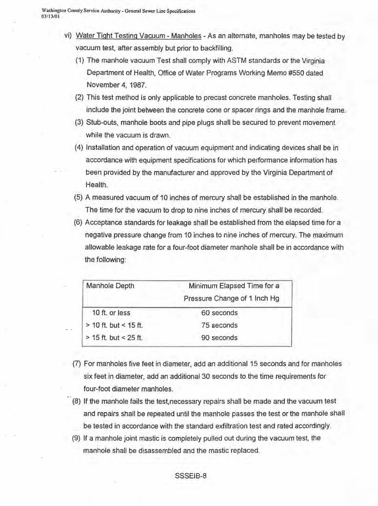
vi) Water Tight Testing Vacuum - Manholes - As an altemate, manholes may be tested by
vacuum test, after assembly but prior to backfilling.
(1) The manhole vacuum Test shall comply with ASTM standards or the Virginia
Department of Health, Office of Water Programs Working Memo #550 dated
November 4, 1987.
(2) This test method is only applicable to precast concrete manholes. Testing shall
include the joint between the concrete cone or spacer rings and the manhole frame.
(3) Stub-outs, manhole boots and pipe plugs shall be secured to prevent movement
while the vacuum is drawn.
(4) Installation and operation of vacuum equipment and indicating devices shall be in
accordance with equipment specifications for which performance information has
been provided by the manufacturer and approved by the Virginia Department of
Health.
(5) A measured vacuum of 10 inches of mercury shall be established in the manhole.
The time for the vacuum to drop to nine inches of mercury shall be recorded.
(6) Acceptance standards for leakage shall be established from the elapsed time for a
negative pressure change from 10 inches to nine inches of mercury. The maximum
allowable leakage rate for a four-foot diameter manhole shall be in accordance with
the following:
Manhole Depth
10ft. or less
> 10 ft. but < 15 ft.
> 15 ft. but < 25 ft.
Minimum Elapsed Time for a
Pressure Change of 1 Inch Hg
60 seconds
75 seconds
90 seconds
(7) For manholes five feet in diameter, add an additional 15 seconds and for manholes
six feet in diameter, add an additional 30 seconds to the time requirements for
four-foot diameter manholes.
(8) If the manhole fails the test,necessary repairs shall be made and the vacuum test
and repairs shall be repeated until the manhole passes the test or the manhole shall
be tested in accordance with the standard exfiltration test and rated accordingly.
(9) If a manhole joint mastic is completely pulled out during the vacuum test, the
manhole shall be disassembled and the mastic replaced.
SSSEIB-8
Washington County Service Authority - General Sewer Line Specifications 03/13/01
4.5 Backfilling (See Part V of the specifications for the specific material requirements bedding,
haunching, initial, and final backfill material and compaction required for each)
a) Haunching - the soil placed at the sides of the pipe from the bedding up to the spring line is
the haunching. The care with which this material is placed has a significant influence on the
performance of the sewer pipe. Care must be taken to carefully and completely tamp under
the haunches of the pipe. Special care shall be taken to avoid damaging or displacing the
pipe during this operation.
i) PVC pipe - for flexible pipe compaction of the haunchng material is essential. The
spring line is defined as 1/2 the pipe diameter. Only Class A or Class B bedding is
acceptable.
ii) Ductile iron pipe - Class A, B or C bedding is acceptable unless otherwise stated on the
plans. If Class C bedding is used the pipe shall be haunched to 1/4 the pipe diameter.
b) Initial Backfill:
i) All trenches shall be backfilled by hand or other approved method with approved
material in layers not exceeding 6 inches, from the top of the haunching material to a
depth of 1 foot above the pipe.
ii) Material shall be deposited on both sides of the pipe simultaneously and compacted
into place by tamping.
c) Backfilling to Grade:
i) From the point one foot above the pipe, the remainder of backfilling shall be carried up
evenly on both sides of the pipe in increments of not more than two feet
ii) Each layer of earth shall be compacted into place by tamping, before the next layer is
applied. Damage to pipe lines or other structures resulting from compaction shall be
corrected by the Contractor at his expense, before acceptance and before any service
is connected.
iii) In areas where settlement is not critical, and where approved. by the Engineer.
alternate methods of backfilling may be employed, with written approval from the
Utilities' Inspector.
d) Backfill Under Pavement:
i) Backfilling of trenches under existing pavement or proposed pavement shall be layers
of not more than 12 inches thickness and shall be compacted to a minimum of 95%
density as compared to density of the same material when tested in accordance with
AASHO Specification T-99.
SSSEIB-9
Washington County Service Authority - General Sewer Line Specifications 03/ 13/01
ii) Compaction shall be by pneumatic tampers or other approved methods.
iii) Compaction by water will not be permitted under pavement.
iv) All fill material under the pavement shall consist of aggregate base material meeting the
requirements of the Virginia Department of Highways Specification 210 Type I.
v) This material shall be thoroughly and uniformly tamped with pneumatic tampers or other
approved methods.
vi) Moisture content shall be within 20% of optimum.
vii) The Contractor will be responsible for and shall repair any settlement in the backfill or
pavement for a period of one year after completion of the work.
4.6 Restoration
a) Finished Surfaces:
i) Uniformly smooth grading of disturbed areas shall be required after backfill and
compaction.
ii) Finished surfaces shall not be more than 0.10 feet above or below the Original grade or
cross section.
iii) Ditches and gutters shall be finished to drain readily.
iv) In grass or lawn areas the last four inches of compaction fill will consist of topsoil or an
approved soil which will support a turf growth after fertilization and seeding.
v) Settlement or other damage that occurs prior to acceptance of this work shall be
repaired and grades satisfactorily reestablished.
b) Seeding
i) The seeding, fertilizing and mulching of the areas prepared for seeding shall be in
accordance with these specifications and Section 529, Seeding of the Virginia
Department of Highways Road and ;,,8ridge Specifications, using the following quantities
of seed, fertilizer, lime and mulch:
(1) Seed:
(a) Mixture shall be sown at a rate of 2.5 pounds per 1000 square feet in the
following proportion:
(i) Certified Merian Kentucky Bluegrass :40°%
(ii) Certified Kenblue Kentucky Bluegrass Or Certified South Dakota Kentucky
Bluegrass 30°%
(iii) Certified Pennlawn Red Fescue 30%
SSSEIB-10

Washington County Service Authority - General Sewer Line Specifications 03/ 13/0 I
(2) Fertilizer:
(a) Shall be 10-20-10 fade produced by an approved manufacturer.
(b) Fertilizers shall be spread at a rate of 24 pounds per 1000 square feet.
(3) lime:
(a) Shall be ground agricultural limestone spread at a rate of 50 pounds square foot,
(4) Mulch:
(a) Shall be applied to the seeded area at a rate of 100 pounds per 1000 square
feet. and maintained until growth is obtained.
(5) Application:
(a) Seed fertilizer and lime shall be uniform and at the rate specified.
(b) Seed bed shall be loosened to a depth of 4 inches and fertilizer and lime
thoroughly mixed in by discing, harrowing, or railing.
(c) Seed shall be uniformly spread and worked into the soil bed toa depth of at least
half an inch.
(d) Mulch consisting of straw or a similar material shall be spread to a depth of one
and one-half inches over the entire area disturbed.
ii) Planting Season - Shall be between March 15 and May 15 or between August 15 and
November 1 unless otherwise authorized.
iii) Maintenance - Of the seeded area until establishment of an acceptable stand of grass is
obtained shall be the responsibility of the Contractor. Such maintenance shall include
reseeding, where necessary, and the replacement of all mulch destroyed or removed by
any cause.
iv) Alternate Methods - Alternate methods of obtaining an acceptable stand of grass will be
considered upon request to WCSA detailing methods and materials proposed.
c) Replacement of Pavement and Structures: - The Contractor shall restore all pavement,
sidewalks, curbing, gutters, shrubber) fences. poles, or other property and surface
structures removed or disturbed as a part of the work to a condition equal to that before the
work began, as directed by the WCSA Inspector.
d) Cleanup: Cleanup of surplus materials, tools, temporary structures, dirt, rubbish, and
excess earth from the excavation shall be maintained during construction progress as
directed by the WCSA Inspector. At the completion of construction the sites will be left in a
safe and clean condition.
4.7 Sewers Crossing Streams, Estuaries. Lakes, & Reservoirs
a) Sewers entering or crossing the streams shall be constructed of watertight pipe.
SSSEIB-11

Washington County Service Authority - General Sewer Line Specifications 03/13/01
b) The pipe and joints shall be tested in place, shall exhibit no infiltration.
4 .8 Boring, Jacking and Tunneling - This section covers the installation of pipelines using
horizontal earth boring and jacking. Tunneling is not covered by these specifications will
only be considered when it is absolutely necessary. Tunneling will be approved on the
basis of plans and specifications specifically prepared for the project by a registered
professional engineer with tunneling experience.
a) Comply with all codes, laws, ordinances, regulations, and permits of govemmental and
other authorities having jurisdiction over this part of the work. . These may include but are
not limited to
1) Virginia Department of Transportation (VDOT) Road and Bridge Specifications, latest
edition.
2) American Railway Engineering Association (AREA) Specifications, latest edition.
b) The Contractor shall take every precaution to guard against any movement or settlement of
existing or new construction, railways, utilities, paving, walks, light standards, piping,
conduit, etc., and shall provide at his own expense, all sheet piling, bracing or shoring
necessary in connection therewith. The Contractor shall be entirely responsible for the
design, and adequacy of any sheet piling, bracing and shoring required.
c) Product data for steel casing pipe and associated appurtenances shall be submitted prior to
installation, including evidence that pipe and mounting devices complies with the
requirements of these specifications.
d) Highway Crossing
i) Pipeline crossing shall be installed in a steel casing installed by the "dry case as you
go" boring and jacking method.
ii) The pipeline crossing shall be installed as shown on the Drawings.
iii) If the Contractor determines that boring anc ,;:3cking of the highway crossing is not
possible due to rock, the Contractor shall make application to VDOT to allow open
cutting of the crossing. Contractor shall make every effort to bore and jack before
abandoning this method, including use of a rock head. If the trench is allowed to be
open cut, casing pipe shall be provided and the trench shall be backfilled entirely to the
bottom of the pavement base course and the pavement restored in accordance with
VDOT requirements.
iv) All operations of the Contractor shall be subordinate to the free and unobstructed use of
the highway right of way for passage of traffic without delay or danger to life, equipment
SSSEIB-12
Washington County Service Authority - General Sewer Line Specifications 03/13/01 .
or property. The Contractor shall provide all necessary bracing, bulkheads, and shields
to ensure complete safety to all traffic at all times. The Contractor shall arrange for and
pay for all flagmen, signs and other measures required by VDOT.
e) Railroad Crossing - Pipeline shall be installed in steel casing by the "dry case as you go"
boring and jacking method, or by tunneling (not covered by these specifications). The
pipeline crossing shall conform to Roadway and Ballast Section 5.2 - Specification for
Pipelines Conveying Non-Flammable Substances of the American Railway Engineering
Association Manual for Railway Engineering. The pipeline crossing shall be installed as
shown on the Drawings.
i) The live load surcharge from the track adjacent to sheeting and bulkheads for the
excavation pits and for the trench shall be taken into account in the sheeting and
bulkhead design. Allowable stresses contained in the American Railway Engineering
Association Specifications (Chapters 7, 8, and 15) shall be used. A safety factor of two
(2) shall be used in the temporary sheeting or bulkhead design.
ii) Safety railings shall be installed when temporary sheeting or bulkheads are within
fifteen (15) feet of the track.
iii) The Contractor is required to submit for approval through the Engineer to the Railroad a
construction procedure for the temporary sheeting or bulkhead construction. Three
copies of the detailed drawings shall be submitted, showing the following .
(1) Timber, steel, bolt and weld sizes and details.
(2) Dimensions showing distances from centerline track to temporary sheeting or
bulkheads and between supporting elements.
(3) Section showing temporary sheeting or bulkhead heights and track elevation. Also,
calculations covering temporary sheeting or bulkhead design shall be submitted for
approval. The Contractor shall not proceed with the pipe or tunnel liner installation
until he has received acceptance ,')f the pian and schedule from the Engineer and
from the Chief Engineer's Office of the Railroad.
iv) All operations for the Contractor shall be subordinate to the free and unobstructed use
of the Railroad's right of way for passage of traffic without delay or danger to life,
equipment or property.
v) The Contractor shall provide all necessary bracing, bulkheads, and shields to ensure
complete safety to all traffic at all times.
SSSEIB-13
Washington County Service Authority· General Sewer Line Specifications 03/ 13/01
vi) The Contractor shall furnish insurance as specified in the Supplementary Conditions.
The Contractor shall arrange for and pay for all flagman, signs and other measures
required by the Railroad.
vii) Dry Jacked Boring Method
(1) The jacking operation shall be performed in such a manner that settlement of the
ground, railway, or the highway above the pipeline will not occur.
(2) The use of water or other fluids in connection with the boring and jacking operation
shall not be allowed.
(3) Excavation shall not precede the jacking operation more than is necessary.
(4) Lengths of steel pipe shall be welded to the preceding length installed.
(5) Excavation shall be made by auger or manual methods at the Contractor's option to
suit conditions encountered.
(6) The Contractor shall repair or replace, as directed by the Engineer, at his own
expense, casing pipe which is damaged during the jacking operation.
f) Carrier Pipe Installation - After installation of the casing pipe or the tunnel liner, the carrier
pipe shall be installed.
i) Each joint of the carrier pipe shall be supported by casing chocks or other devices as
approved by WCSA or shown on the Drawings.
ii) ' The ends of the casing pipe or the tunnel shall be closed off by concrete or masonry
block wall prior to backfilling. A drain line shall be provided at the lower end and shall
run to a one cubic yard french drain. The drain shall be constructed of cement lined
ductile iron pipe or alternative material acceptable to the Engineer.
SSSEIB-14
Washington County Service Authority - General Sewer Line Specifications 03i 13/0 I
PART V
SANITARY SEWER SPECIFICATIONS
TECHNICAL SPECIFICATIONS
MATERIALS
5.1 Pipe - Sanitary sewer and lateral pipe shall be one of the following materials, at the
Contractor's option, except when otherwise indicated on the plans.
a) PVC Pipe:
i) PVC pipe for sewers and laterals shall be in accordance with ASTM. 03034. The walls
shall have a minimum thickness of DR - 35.
ii) The pipe shall have integral bell and spigot joints.
iii) Bell and spigot joints shall be supplied with a rubber O-ring to provide for contraction
and expansion so as to insure water tightness.
iv) All fittings shall have identical bell and spigot configurations as the pipe and shall be
supplied by the same manufacturer as the pipe.
v) Where PVC pipe is used and the line of sight is restricted between manholes, metal
pipe detection tape shall be placed in the trench with the pipe in. The tape shall be
installed in accordance with the tape manufacturers recommendations.
b) Ductile Iron Pipe:
i) Ductile Iron pipe shall be in accordance with AWNA C151/ANSI A21 .51 .
ii) Pipe thickness shall conform with AWNA C150/ANSI21.50.
iii) All pipe shall be cement mortar lined in accordance with AWNA C104/ANSI21.4,
except that the lining shall be "enameled" or 1/2 the normal thickness.
iv) Buried ductile iron pipe shall have push-on joints, unless otherwise specified on the
Drawings.
v) The pipe shall be minimum Class 50 for nominal diameters 6-inch and larger and Class
51 for pipe diameters less than 6-inch.
vi) Joints shall be rubber gasket jOints in accordance with AWNA C111/ANSI A21.11.
vii) Outside coating shall be asphaltic.
c) Plugs or Cans:
i) Plugs or caps used shall be those manufactured specifically for the type of pipe used.
SSSM -1
Washington County Service Authority. General Sewer Line Specifications 03/13/01
ii) They shall be secured such that they will be watertight and will withstand the internal
pressure applied by air or exfiltration testing.
2) 5.2 Manholes:
a) Materials
i) Manholes shall be constructed of precast reinforced concrete conforming to ASTM C
478. Concrete shall be minimum compressive strength of 4000 psi at 28 days.
ii) Manholes shall be equipped with cast iron frames and covers as shown on the standard
details.
iii) All reinforcing steel shall conform to ASTM A615
iv) Manholes steps shall be steel encapsulated in corrosion resistant rubber or copolymer
polypropylene plastic, as manufactured by Delta Pipe Products (WEDGLOK), Model
#PS1-PF as manufactured by M.A. Industries, or equal.
b) Dimensions
i) Manholes shall have an inside diameter of four (4) feet unless otherwise shown on the
Drawings.
ii) Minimum wall thickness shall be five (5) inches.
c) Configuration
i) Base units shall be tub or monolithic type with walls that extend above the top of the
largest inlet or outlet pipe.
ii) Joints shall be O-ring joints conforming to ASTM C~43. Joints shall be sealed with
flexible butyl resin sealant conforming to Federal Specification SS-S-210A and
AASHTO M198
iii) Each unit shall have no more than two (2) holes for installation and/or handling. All
holes shall be plugged with rubber stoppers and mortared upon completion of setting
manhole.
Iv) Manhole top units shall be eccentric taper type, at least three (3) feet ;, height, or flat
top where indicated.
v) Manholes shall be constructed to the required height to insure that the top of the frame
and cover will be set at finished grade, unless specified or indicated otherwise. Spacer
rings or other means shall be provided to allow up to eight (8) inches adjustment to final
pavement. .
d) Manhole steps
i) shall be provided in all manholes
SSSM - 2
Washington County Service Authority - General Sewer Line Specifications 03/13/01
ii) shall be on 16" center maximum, vertically aligned and uniformly spaced for the entire
depth of the structure.
iii) Steps shall be located in the structures so as to land upon a bench ..
iv) Steps shall be in accordance with the dimensions and capable of withstanding the loads
specified in ASTM C478, and shall be designed for installation in a sanitary sewer.
v) Steps shall be required in all structures with a depth greater than four (4) feet.
5.3- Manhole Connections
a) Sanitary sewer pipe connections to manholes shall be flexible connections
i) Manhole connections to gravity sewer line shall be made to maintain a flexible
connection by utilizing rubber gaskets cast integrally in the manhole base at the time of
manufacture.
ii) Rubber gaskets shall conform to ASTM C443 and shall meet the performance and test
requirements of ASTM C425.
iii) Flexible connections shall be A-LOK Manhole Pipe Seal, manufactured by A-LOK
Corp., or equal.
iv) As an alternate, and for connections to existing manholes, connections may be made
utilizing field installed positive seal gasketing systems. Field installed connections shall
be PSX, manufactured by Press Seal Gasket Corporation; KOR-N-SEAL,
manufactured by National Pollution Control Systems, Inc.; or equal.
5.4 Manhole Frames and Covers
a) Manhole frames and covers shall be cast ductile iron in accordance with the dimensions
shown on the standard details.
b) Minimum opening diameter shall be 24 inches. The words "SANITARY SEWER" shall be
cast in the cover so as to be plainly visible.
c) :asting shall be manufactured true to pattern with component parts fitteLJ together in a
satisfactory manner.
d) Frames and covers shan-have machined bearing surfaces to prevent rocking or rattling.
Castings shall be uniform in quality, without defects.
e) Standard manhole frames and covers shall be GTS, manufactured by Quality Water
Products, or equal.
f) Watertight manhole frames and covers shall be PAM-TIGHT, manufactured by Quality
Water Products, or equal.
SSSM - 3
Washington County Service Authority - General Sewer Line Specifications 03/ 13/01
g) Anchor bolts shall be supplied by manufacturer
5.5- Manhole inverts
a) The invert channels of manholes shall be smooth and semi-circular in shape
b) The invert channels shall be sized to match the inlet and outlet pipes and sloped to provide
a smooth transition between the inlet and outlet pipes.
c) Changes in direction of flow shall be made with a smooth curve channel with a radius as
large as the base will permit.
d) The invert channels and benches may be formed directly in the concrete base unit of the
manhole or may be constructed with brick and mortar. The benches shall slope a minimum
of two (2) inches per foot toward the invert channel.
e) The surface of the channels and benches shall be concrete.
f) Modified shaping, defined as a channel two-thirds the height of the largest pipe, shall be
acceptable.
5.6 Grout
a) Aggregate shall be clean, washed natural sand, free from dirt and foreign material, in
accordance with ASTM C 144.
b) .Portland Cement shall be Type II, in accordance with ASTM C150.
c) Water shall be clean and free from injurious amounts of oil, acid, alkali, organic or other
deleterious matter.
d) Grout used for shaping invert channels and filling connection openings shall be composed
of two (2) parts aggregate and one (1) part Portland Cement, mixed in accordance with
ASTM C270.
5.7 Cleanouts
a) Sewer clean-outs shall be constructed of Schedule 40 PVC pipe, unless otherwise
indicated, which is the same diameter as the sewer main it is servicing.
b) Clean-outs shall be threaded to accept pipe plug.
5.8 Steel Casing Pipe
a) Steel casing pipe shall conform to ASTM A139, Grade B (No Hydro).
b) Joints shall be butt welded, watertight in accordance with the American Welding Society's
recommended procedures.
SSSM - 4
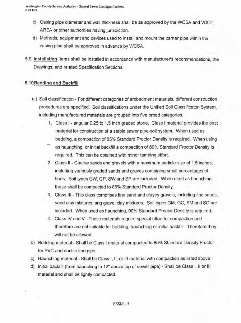
Washington County Service Authority - General Sewer Line Specifications 03/13/01
c) Casing pipe diameter and wall thickness shall be as approved by the WCSA and VDOT,
AREA or other authorities having jurisdiction.
d) Methods, equipment and devices used to install and mount the carrier pipe within the
casing pipe shall be approved in advance by WCSA.
5.9 Installation Items shall be installed in accordance with manufacturer's recommendations, the
Drawings, and related Specification Sections.
5.10 Bedding and Backfill
a.) Soil classification - For different categories of embedment materials, different construction
procedures are specified. Soil classifications under the Unified Soil Classificaton System,
including manufactured materials are grouped into five broad categories.
1. Class I - angular 0.25 to 1.5 inch graded stone. Class I material provides the best
material for construction of a stable sewer pipe-soil system. When used as
bedding, a compaction of 85% Standard Proctor Density is required. When using
as haunching, or initial backfill a compaction of 80% Standard Proctor Density is
required. This can be obtained with minor tamping effort.
2. Class II - Coarse sands and gravels with a maximum particle size of 1.5 inches,
including variously graded sands and graves containing small percentages of
fines. Soil types GW, GP, SW and SP are included. When used as haunching
these shall be compacted to 85% Standard Proctor Density.
3. Class III - This class comprises fine sand and clayey gravels, including fine sands,
sand clay mixtures, ang gravel clay mixtures. Soil types GM, GC, SM and SC are
included. When used as haunching, 90% Standard Proctor Density is required.
4. Class IV and V - These materials require special effort for compaction and
therr.fore are not suitable for bedding, haunching or initial backfill. Therefore :'hey
will not be allowed.
b) Bedding material- Shall be Class I material compacted to 85% Standard Density Proctor
for PVC and ductile iron pipe.
c) Haunching material- Shall be Class I, II, or III material with compaction as listed above
d) Initial backfill (from haunching to 12" above top of sewer pipe) - Shall be Class I, II or III
material and shall be lightly compacted.
SSSM - 5

Washington County Service Authority - General Sewer Line Specifications 03/\3/01
e) Final backfill may native material however it shall be free of mud, refuse, construction
debris, organic materials, frozen materials and rocks greater than 4" in any dimension.
SSSM -6
Section VI
Standard Details

VV'y:::Jf\ :::Jlanaara uetall :::JU" t<tlNr UHCED STEEL PER SPEC. '
: cow 'z -0
Nt)
5U
U1 (TYP.)
U1 w ....J
~ 0
0 GROUT I v FILL
r i I J" I .-
STEPS (SEE STD. DETAIL)
-------
a.. >I-
to ....
, co . - --48" DIA.-:
z . :::iE
.. ,-_-. L
1.1.- 48" OIA. 58" DlA. --.-..
. . . ' . .
A~T~ TOP , "F<9R" ,SHALLOW. MANtfOLES'" (FlA nop)
ON WATERTIGHT COVER (SEE STD. DETAIL)
O-RING JOINT (TYP)
ALL LIFT HOLES TO BE GROU TED
BELL END ON INCOMING PIPES (AS SHOWN)
&---41- 2" MIN.
PLAIN END ON OUTGOING PIPE (AS SHOWN)
TYP.
BENCH TO € OF LARGEST PIPE
1'-0" MIN.
. 2M TYP.
l' -0" MIN. ANTI-FLOATATION FOOTING EXTENSION
NOTE: MATERIALS AND F ABRICA TION IN ACCORDANCE WITH ASTM C478-72.
MONOLITHIC BOTTOM
STANDARD -MANHOLE NO.1 SANITARY. SEWER
PRECAST STANDARP -M:AN-HOLE
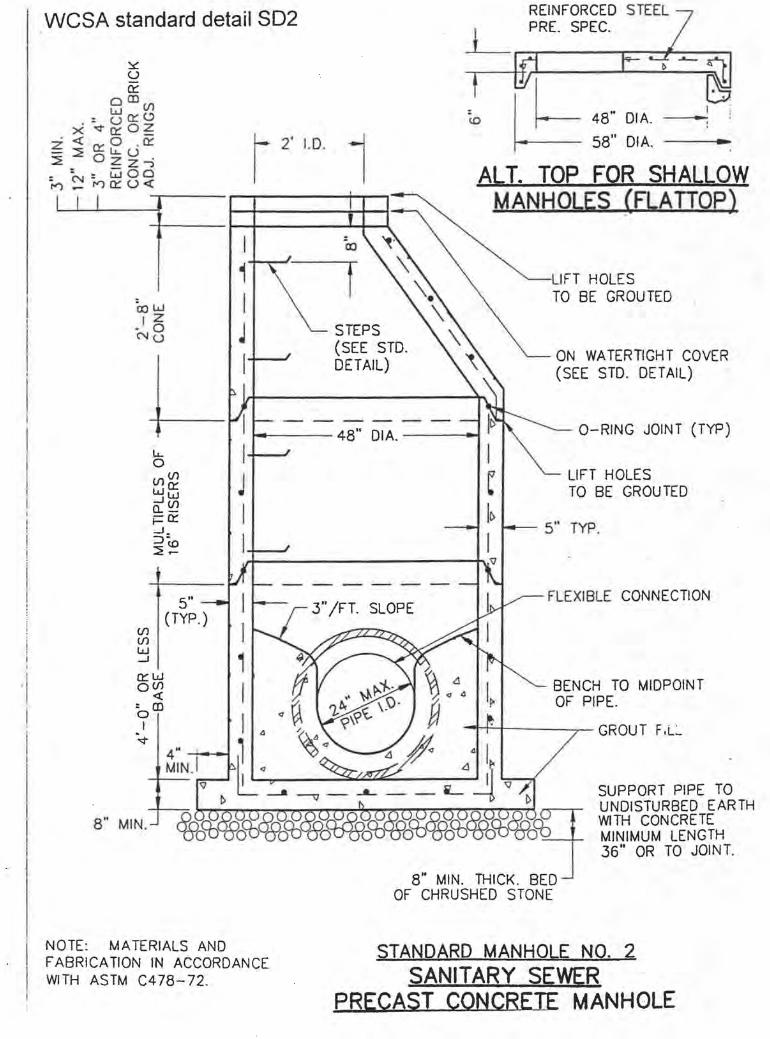
, WCSA standard detail SD2
Cow 'z -0
NU
I 1-+--0--1'
I J I
STEPS (SEE STD. DETAIL)
REINFORCED STEEL PRE. SPEC.
1.1- 48" OIA. ----.; 58" OIA. -
ALT. TOP FOR SHALLOW MANHOLES (flATIOP)
LIFT HOLES TO BE GROUTED
ON WATERTIGHT COVER (SEE STD. DETAIL)
t---- 48" DIA. -----' O-RING JOINT (TYP)
, .1 I i
Cf) Cf) W -l
a::::w o(f) ~
: CD o I
"<t
8" MIN.
4"~:~ MIN .I
NOTE: MATERIALS AND F ABRICA TION IN ACCORDANCE WITH ASTM C478-72.
3" 1FT. SLOPE
LIFT HOLES TO BE GROUTED
FLEXIBLE CONNECTION
BENCH TO MIDPOINT OF PIPE.
-H-=--t----~ GROU T F.L:_
SUPPORT PIPE TO UNDISTURBED EARTH WITH CONCRETE MINIMUM LENGTH 36" OR TO JOINT.
STANDARD MANHOLE NO.2 SANITARY SEWER
PRECAST CONCRETE MANHOLE
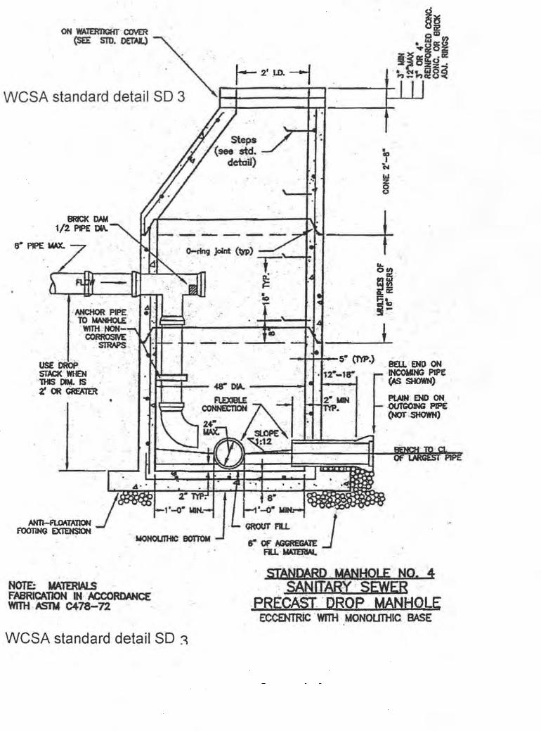
ON WAl£RI1GHT COVER (SEE . STD. DET.A,I.)
WCSA stand~rd detail SO 3
i' c.. ... z 8
. ......,. J<Mt (w) T: ... · . -i .. ,.L...--f"h--~~';:-tIl , ~,' ' ~~
' NfCHOR 'PIPE " , TO~"',
WITH.:,.cN'- , " CORROSIVE ' ,
,' SJRAPS "
• , ,, 00
;~
-t:''''t'-r'-5- ('NP.) ', saL' END ON
fE=a~ -48'" 0fA.. --:----1
'2.~ t- ' INCOMING PIPE • 1 - g -, (AS SHOWN)
N()'T'& MAlmIALS .. , FABRICATION IN ACCORDANCE WIDi As1V C478-n .
WCSA standard detail SO ~
t=A} , £~!E'\ ,I;...:" :::!:' =' ==~ " :12 , r-
8"
~.~J , FI.L. MAltRMl.
, stANDARD , t(ANI:IOLE NQ, 4 , ', SANITARY ' SEWER
PRECAST 'DROP , MANI;tOLE Ee¢ENTRiC 'WITH ,MO.NOUTliIC BASE

3/8"
3/8"
;'-:7 ' 5/8" -' -~
2 SLOTS 3/4" x 1 1/2"
.-,. ': ' TOP' OF COVER
1 ':- 9 3 / 4~' . 1 ' _ 9 3/4" ..
USE SOLID COVER ' AND· '" ". , ~' " , .' 1 1/2" \ , ;
. ~. -~ : I
BOTTO~ OF qOVE~ .. ~ ' . , . r' 3/4" " ' :'-" '., ' ;
CONCEALED LIFTING HO!-E 1/4" 3/f5'~... 3/4'~." i r;)' J-- 3/4" ; I WHEN TOP IS BURIED ". ~ --:- . ~ ~ BELOW GRADE ,,-.l..-Tt --=. ¢. ==-'" ~F?77'/77h?5;::r:9Jm~?77;~'77375-.?'77jn22'2L;r;': n'Y/7h~~~~ ~ i" '.
3/4 ." ~ . " F .. iti>~ .Jt ' .
----l1--1 /4"
PLAN
1"~11-10"~ , ~ 1'-8 1/4" . .
7/8" r-.....-- MACHINE ' ,
I t3~8'.: _ --: __ y4·~CT ; ,"". ~: .1'.-8 1/8" :., -t:
SECTlOO;" ~A : : ..
""" NOTE: THE LEITERS" " ARE TO BE CAST IN THE DEPRESSION IN TOP .OF COVER 1" WIDE AND RAISED
;' .. 3/S" HIGH AS SHOWN
APPROXIMATE WEIGHT CAST IRON -----,-1
ctz:zzfl:.===========3=/ 4="==::::Y:z:Z2~:zZlt{/ 4" 8~' WCSA standa rd detail S D4
-1 5"~ r-.. I----- 2' - 0" --' "- " '--t-! - [
FRAME: 239± 12 LBS, COVER: 137± 7 LBS.
SECTION 8-8 3/4" STANDARD MANHOLE
.. -:; , ~F~AW·5v_..l4fr· G·QVEB , " , '-". ~ .. ,

A
NOTE: UNIT SIMllIAR TO DEWEY BROTHERS INC. RCR-3000W
MINIMUM AVERAGE WEIGHT
FRAME: 262 COVER: 170 TOTAL: 432
3-1" DIA. HOLES @ 120'
PLAN GASKET IN VERTICAL FACE OF COVER
28 1/4"
26 1
26" .
.. 1 /t' ~ .. S.S. ROD r 1 3/8"
~~~~~~~~~~~~~\~
t 7 1/2"
24" t j ~~---------2-8'-' --------~~
1"
34" 3" ---I
SECTION A-A
WCSA standard detail SD5
WATERTIGHT MANH,OLE FRAME & COVER
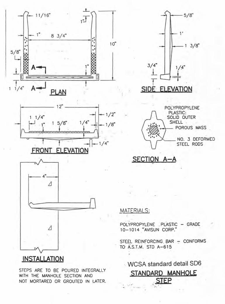
-0- 11/16"
- I-- 1" 8 3/4" '. t ,
• ••
5/8" • •
~ A~ 'm E+
T A.J 1 1/4" PLAN
1 2"
..L('\
l J
,t
t ' • , . • •
1"
~ ~m
t
. . .
~
10"
1/2"
1/8"
.-. -11- 1/ 4" FRONT ELEVATION
:
4"
LI
I/'-. n '\
L1
INSTALLATION
STEPS ARE TO BE POURED INTEGRALLY WITH THE MANHOLE SECTION AND NOT MORTARED OR GROUTED IN LATER.
. .
3/4"
· L T I
1---- 5/8"
1 3/ff'
1/.4"
~ -. SIDE· ElEVATION
POLYPROPYLENE PLASTIC:
SOLID OUTER SHELL · .
-+-- POROUS . MASS
'-_ NO. 3 DEFORMED STEEL RODS
SECTION A-A
MATERIALS:
, POLYPROPYLENE .• PLAsTIC - GRADE 10- 1014 "AVISUN CORP."
STEEL REINFORC1NG BAR - CONFORMS ...... - ', ' . ., "'
TO' A.S.T.M. STO A-615
. WCSA standard detail S06
STANDARD MANHOLE , STEP ':; . ' .. -. - .... :" - - .. ' . ""': . .
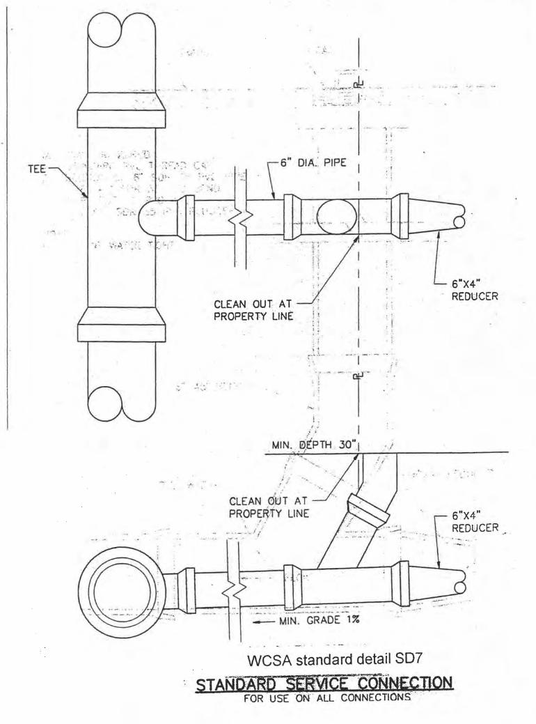
."" TEE
• .. .~ .' ... . :"01 : ... :
CLEAN ,OUT- AT PROPERTY tJNE
.=-""
',:, " ,:.~ ....... <.J., , :. ':~ .., __ ~:;;~: J:,
DIA.: PIPE
1 I
I ~ . , : :
I'
, I . ,
: . : '
,: : :. , .
: I
r" .. ,,~', - .. : -~ ·'~i- ' ~~ - .): :. ~
• ~ • L
:'", 1
I ; .
.. f; J-
MIN" ,e:iPTH .l-.·- .......
t .........
,,!
o' r'
,6"X4" REDUCER
:; ./ --.., ' . r' ." . , .::
CLEAN 0'0 TAT PROP~~TY LINE
___ "" ~ -:." "_- i /
"
I--..-! .. . . ... _,_. , _.' J------............... _ MIN. GRADE 1%
. " - . - ' - .. -.- - , .
;. - .. . .
WCSA standard detail SO?
sTANllAfW .ViCE ·, CONNLeTlON FOR USE ON' ALL CONNECTIONS'·' '
6"X4" REDUCER

MATERIALS REQUIRED 1. . STANDARD PVC THREAD •. ~~ .... . . 2. SECTION 'OF 6·SOR35' PVC 'PIPE 3. 1-6" 45' SDR 35. Pi¢. :BENO .... .. . 4 1-6" SOR35PVCWYE:'" " . .. , ',. '. ,'. -', .,." . . " . ."
5. 1-6 x4 ' : SDR35 .PVC' REDUCER ·' ' , 6. 1-NEENAHFOUNORY lAMP~ HOLE FRAME,
AND COVER --~----..
' NOTE: MAKE JOINT WATERTtGH'r .. " , .. ..
"
" <
... , I • • ,"
.,
" , ' .
. .
STD. WYE .
• FLOW
, WCSA standard detail. SOB SANlTARYSEWER SfANDARL}'.: .ClJtANQUI ' .

2500# CONe. "
6" VARIES
0.0. OF PIPE
. Ne:>T TO SCALE LENGTH TO "DEPEND ON FIELD cqNDfTroNS
WCSA standard detail S09·
CONCRETE ·· ENCASE"MENT QF . . . ~, ~
SANITARY SEWEa· ,,~LLNES· ·

USE TWO LAYERS OF ; 15 LB., ~UILDER'S FELT ON PLUGS
.,
DIRECTION OF THRUSL'.OR " BISECTOR OF Pl-P£ BEND · ".,
"'. ". - -.0 " 0 '
. .."
:~ ' . . . .' .... ' . . . ".. II
.' . ".. ; " . .,.
PLAN
T
. '
DIAMETER OF PIPE' + 6"
T
The value of "T" is case dependent. Please call WCSA - engineering to Obtain this value if it is riot stated on Plans for the project.
+ 0'
WCSA standard detail SD10
CONCRETE ANCHOR FOR BENDS. TEES. & -PLUGS

)
STONE '-BASE
, a ~ a a .. .. a .. a • ' .....
I
.... ' , h . : .. ..
; . ..... "
. .. ' ." ~; ,I ~, ;:'!>~ A,
. ;..0";. • .. ' , c- ,t.,.. ~
1 1/2 TIMES ORIGINAL PAVEMENT
V.D.H. & T. 21A PaM. --~L . ... . .... .. . .. ... .. t ·, ,. '.
WCSA standard detail S011
~RQAD CROSSING :~-QETAtL . • i" . ' .. . :,.::..... " .... ... .. ,~2"~"";;~-: .. .... "":·.·I~··· .... - .
o )
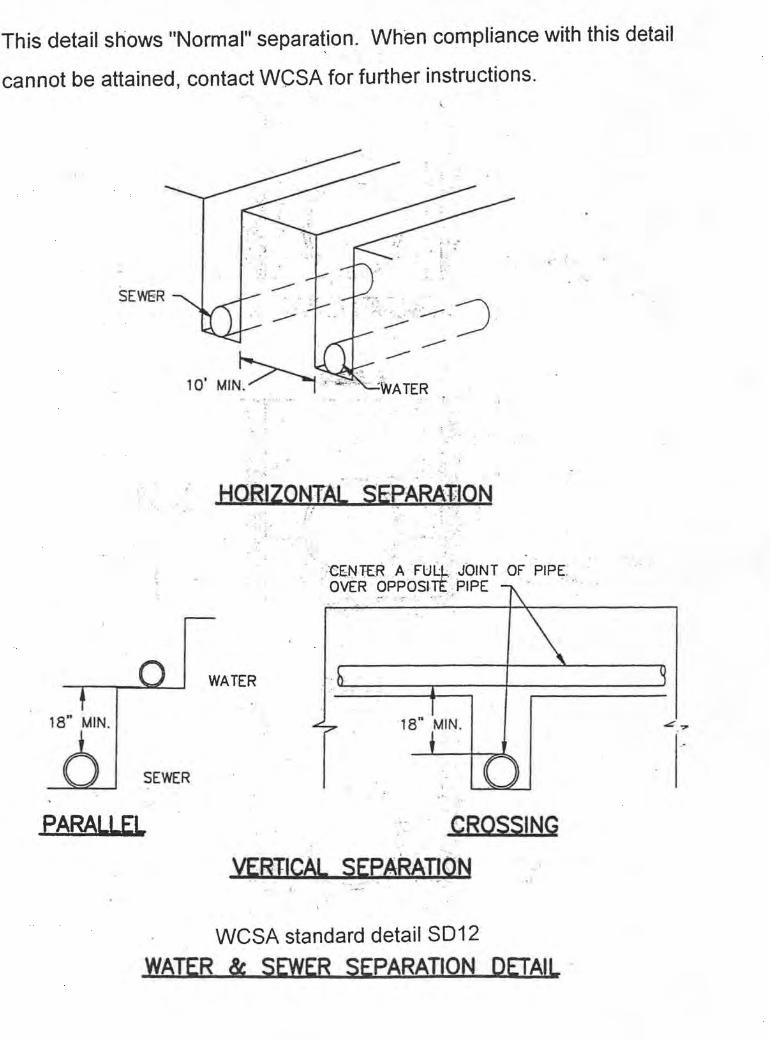
This detail shows "Normal" separa~ion. When compliance with this detail
cannot be attained, contact WCSA for further instructions.
SEWER
.. - '~ ~,- ...
. ... . . '
HQRIZONTAL SEPARAlION • .:- ,0: - ~ - .•. • " •
-. .
'-CENTER A FULl,;. -JOINT OF PIPE: OVER opposnt PIPE
.- . . " ' ,' - ,
WATER
18" MIN. 18" MIN. ~.?
SEWER
PARALLEL CROSSING
.,
WCSA standard detail S012
WATER & SEWER SEPARATION DETAIL '

see plans or specifications for Class of bedding required
D DENSELY COMPACTED
. ~ACKf.ILL
1/4 0
<U$S,A 0+8" MIN.
. :... . . .. .. ... ..
MIN.
".. .. - ..
-.
. . ,
CONCRETE ""~--2000 PSI MIN. 4" MIN. ;:
.~--~~~~~~~~~~~~~~
DENSELY COMPACTED BACKFill
1/2 D.
4" MIN.
LIGHTLY COMPACTED BACKFill
1/4 0 4" MIN.
,-
Q,ASSC
.. \
.. . ......
, .. " \
--t."C~-- COMPACTED GRANULAR
- . . ' "
-' .
MATERiAL . ~
MIN . . -
COMPACTED GRANULAR .-.....w--- MATERIAL

see plans or specifications for Class of bedding required
' ·CLAss A
o DENSELY COMPACTED
BACKFILL
1/4 0 4" MIN.
DENSELY COMPACTED BACKFILL
1/2 D.
4" MIN.
LIGHTLY COMPACTED BACKFILL
1/4 0 4" MIN.
0+8" MIN.
Q,ASSB
ClASS C
CONCRETE ~~--2000 PSI MIN.
I MIN.
~"X--- COMPACTED GRANULAR MATERIAL
MIN . . -
COMPACTED GRANULAR ~~-- MATERIAL