Washer, Electrical Equipment Bond WEEB - CED ... UIR...3098177 Document Number 104-0404-000074-003...
20
3098177 Document Number 104-0404-000074-003 2012 BURNDY LLC. Page 1 of 20 Washer, Electrical Equipment Bond WEEB INSTALLATION INSTRUCTIONS For RBI Solar Groundmount Only Please read carefully before installing. Burndy LLC recommends that the sufficient details of the installation be submitted to the AHJ for approval before any work is started. WEEB-11.5 WEEB-UIR Products are tested to UL 467, CAN/CSA-C22.2 No. 41 US/ Canadian standards for safety grounding and bonding equipment. WEEB-LUG-6.7
-
Upload
phungxuyen -
Category
Documents
-
view
214 -
download
0
Transcript of Washer, Electrical Equipment Bond WEEB - CED ... UIR...3098177 Document Number 104-0404-000074-003...
3098177
Document Number 104-0404-000074-003
© 2012 BURNDY LLC.
Page 1 of 20
Washer, Electrical Equipment Bond
WEEB
INSTALLATION INSTRUCTIONS
For RBI Solar Groundmount Only
Please read carefully before installing.
Burndy LLC recommends that the sufficient details of the installation be
submitted to the AHJ for approval before any work is started.
WEEB-11.5 WEEB-UIR
Products are tested to UL 467, CAN/CSA-C22.2 No. 41
US/ Canadian standards for safety grounding and bonding equipment.
WEEB-LUG-6.7
Document Number 104-0404-000074-003
© 2012 BURNDY LLC.
Page 2 of 20
Contents:
5/16" hardware and WEEB-11.5.........................................3-9
Modules in Portrait Configuration....................................4-6
Modules in Landscape Configuration..............................7-9
1/4" hardware and WEEB-UIR...........................................10-16
Modules in Portrait Configuration...................................11-13
Modules in Landscape Configuration.............................14-16
Layout of WEEB-11.5 and WEEB-UIR..............................17
Layout of WEEB-LUG-6.7...................................................18-20
Document Number 104-0404-000074-003
© 2012 BURNDY LLC.
Page 3 of 20
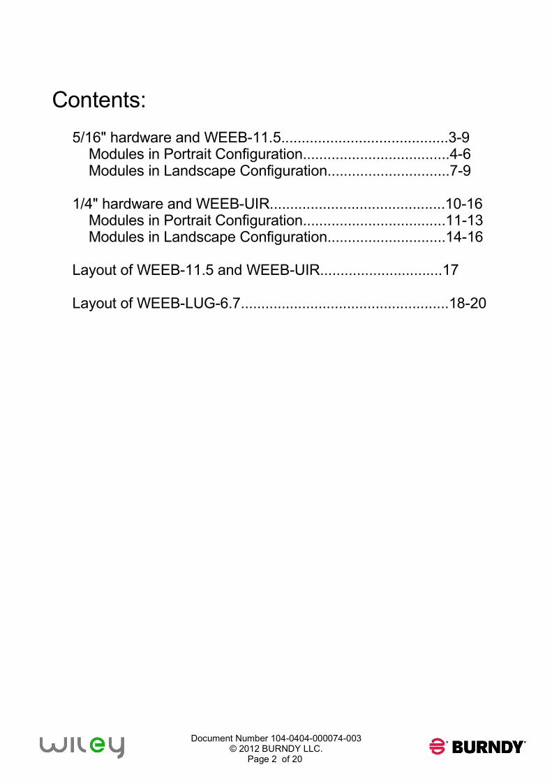
The WEEB family of products can be used to bond anodized aluminum, galvanized steel, steel
and other electrically conductive metal structures. All installations shall be in accordance with
NEC requirements in the USA and with CSA C22.1 in Canada. The WEEBs are for use with
modules that have a maximum fuse rating of less than 25A.
Bottom Mounting Modules
The WEEBs used for bonding the PV modules to the mounting rails are compatible with various
cross-sections of module frames. The following is an example of a module frame that is compatible.
Notice that the WEEB teeth are positioned completely under the edge of the module frame.
WEEB COMPATIBILITY
Note:
Inspect each module frame used with a WEEB to ensure that the bottom mounting face of
the frame is flat, and that there are no hindrances to embedding WEEB teeth. Do not use a
module with a frame that prevents the WEEB teeth from embedding fully.
5/16" Hex Bolt
5/16" Hex Washer
WEEB-11.5
7/16" flat washer
to accomodate for
WEEB "Leg" features
5/16" Serrated
Flange Nut
Module Frame
WEEB "Tooth"
feature
WEEB "Leg" feature
Z-Purlin
Document Number 104-0404-000074-003
© 2012 BURNDY LLC.
Page 4 of 20
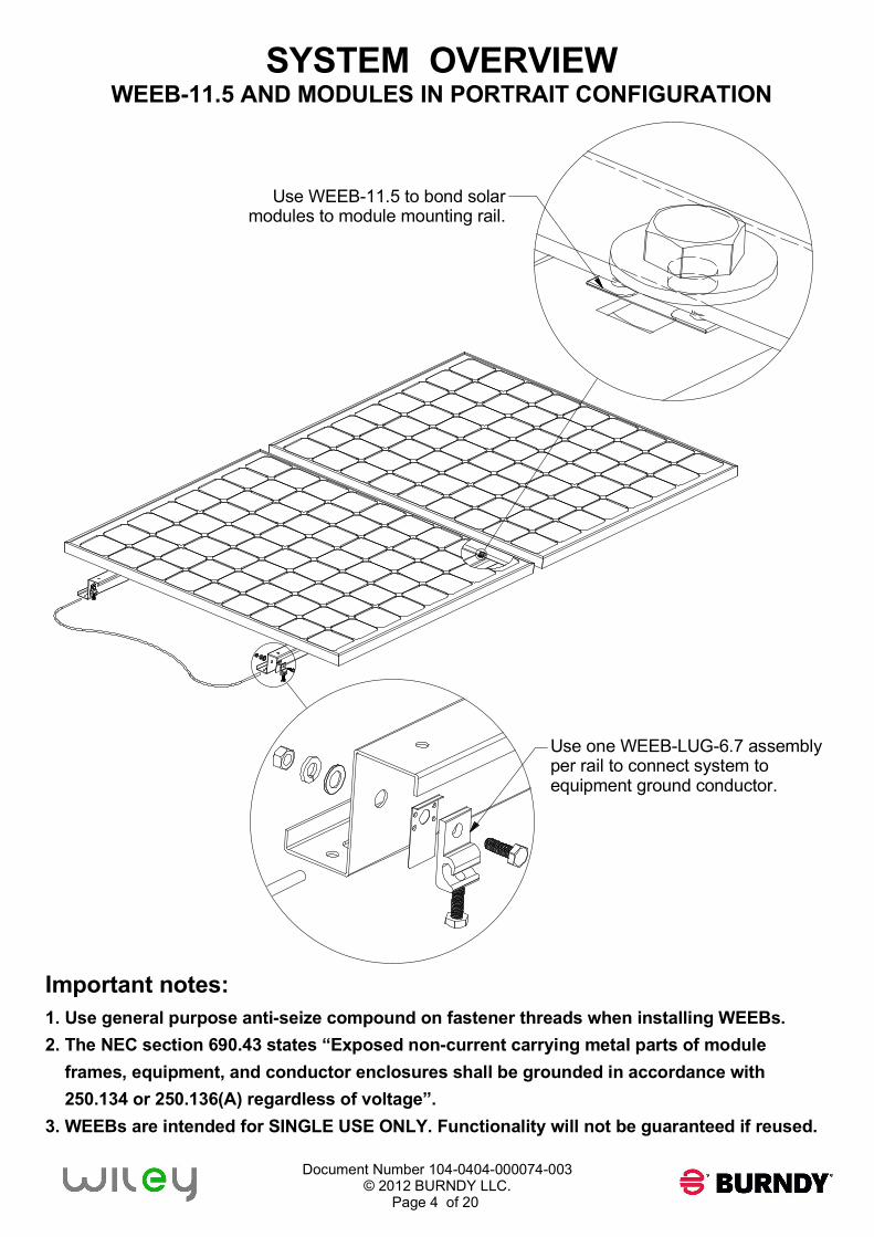
SYSTEM OVERVIEW
WEEB-11.5 AND MODULES IN PORTRAIT CONFIGURATION
Important notes:
1. Use general purpose anti-seize compound on fastener threads when installing WEEBs.
2. The NEC section 690.43 states “Exposed non-current carrying metal parts of module
frames, equipment, and conductor enclosures shall be grounded in accordance with
250.134 or 250.136(A) regardless of voltage”.
3. WEEBs are intended for SINGLE USE ONLY. Functionality will not be guaranteed if reused.
Use WEEB-11.5 to bond solar
modules to module mounting rail.
Use one WEEB-LUG-6.7 assembly
per rail to connect system to
equipment ground conductor.
Document Number 104-0404-000074-003
© 2012 BURNDY LLC.
Page 5 of 20
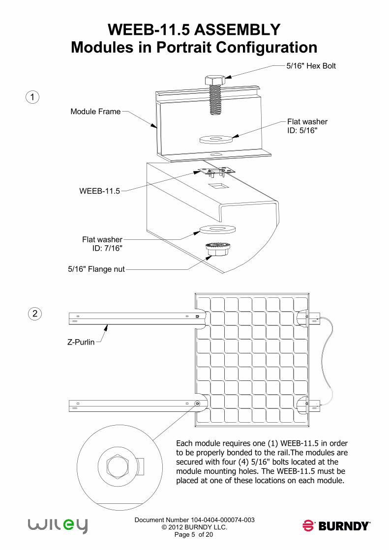
WEEB-11.5 ASSEMBLY
Modules in Portrait Configuration
Each module requires one (1) WEEB-11.5 in order
to be properly bonded to the rail.The modules are
secured with four (4) 5/16" bolts located at the
module mounting holes. The WEEB-11.5 must be
placed at one of these locations on each module.
WEEB-11.5
Module Frame
Flat washer
ID: 7/16"
5/16" Flange nut
Flat washer
ID: 5/16"
5/16" Hex Bolt
Z-Purlin
1
2
Document Number 104-0404-000074-003
© 2012 BURNDY LLC.
Page 6 of 20
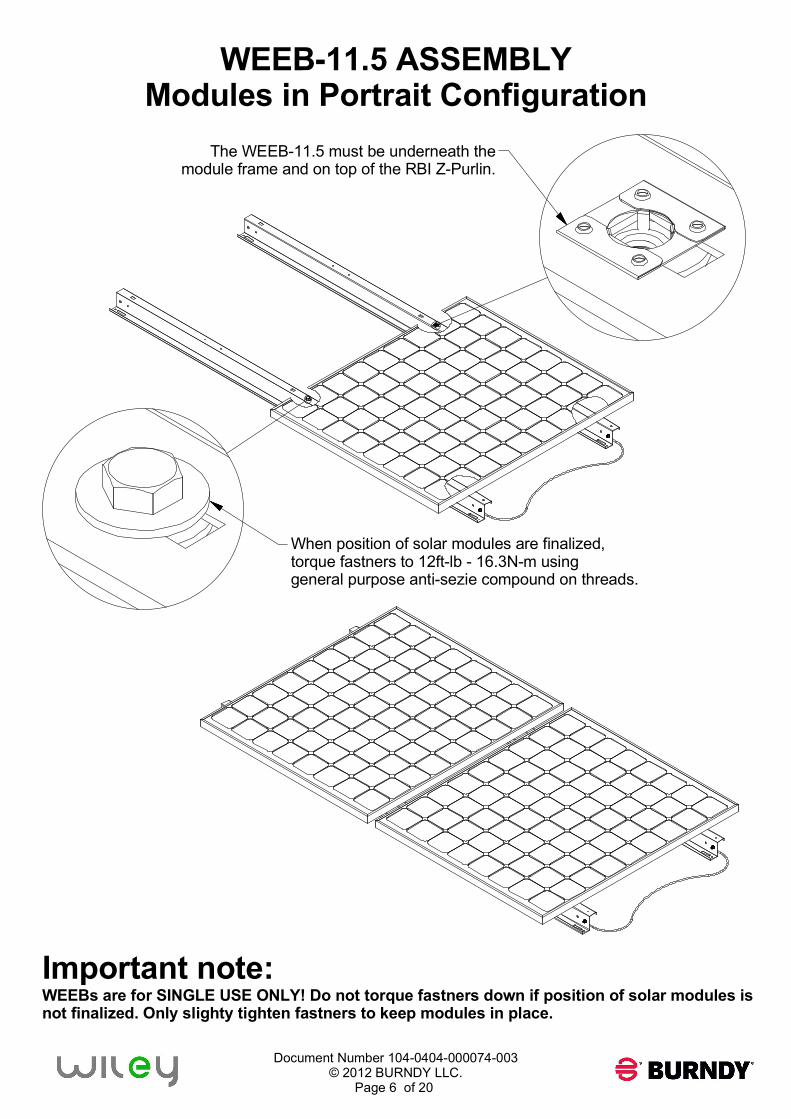
WEEB-11.5 ASSEMBLY
Modules in Portrait Configuration
Important note:
WEEBs are for SINGLE USE ONLY! Do not torque fastners down if position of solar modules is
not finalized. Only slighty tighten fastners to keep modules in place.
When position of solar modules are finalized,
torque fastners to 12ft-lb - 16.3N-m using
general purpose anti-sezie compound on threads.
The WEEB-11.5 must be underneath the
module frame and on top of the RBI Z-Purlin.
Document Number 104-0404-000074-003
© 2012 BURNDY LLC.
Page 7 of 20
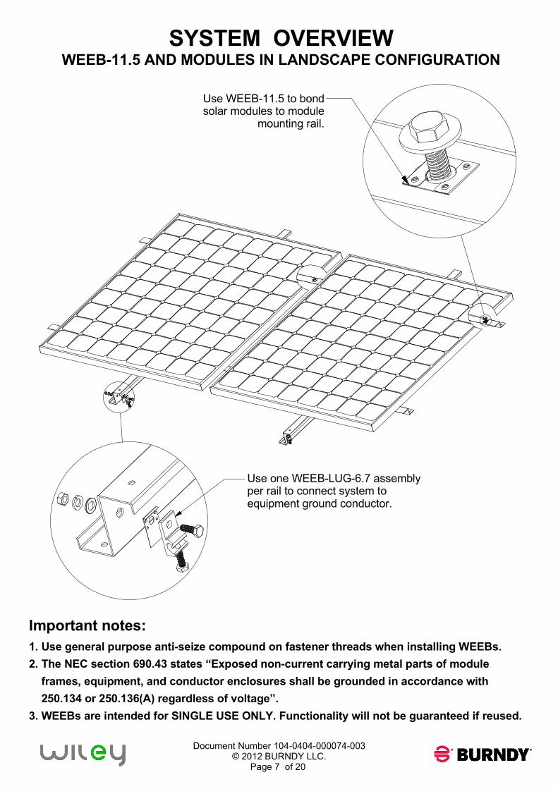
SYSTEM OVERVIEW
WEEB-11.5 AND MODULES IN LANDSCAPE CONFIGURATION
Important notes:
1. Use general purpose anti-seize compound on fastener threads when installing WEEBs.
2. The NEC section 690.43 states “Exposed non-current carrying metal parts of module
frames, equipment, and conductor enclosures shall be grounded in accordance with
250.134 or 250.136(A) regardless of voltage”.
3. WEEBs are intended for SINGLE USE ONLY. Functionality will not be guaranteed if reused.
Use WEEB-11.5 to bond
solar modules to module
mounting rail.
Use one WEEB-LUG-6.7 assembly
per rail to connect system to
equipment ground conductor.
Document Number 104-0404-000074-003
© 2012 BURNDY LLC.
Page 8 of 20
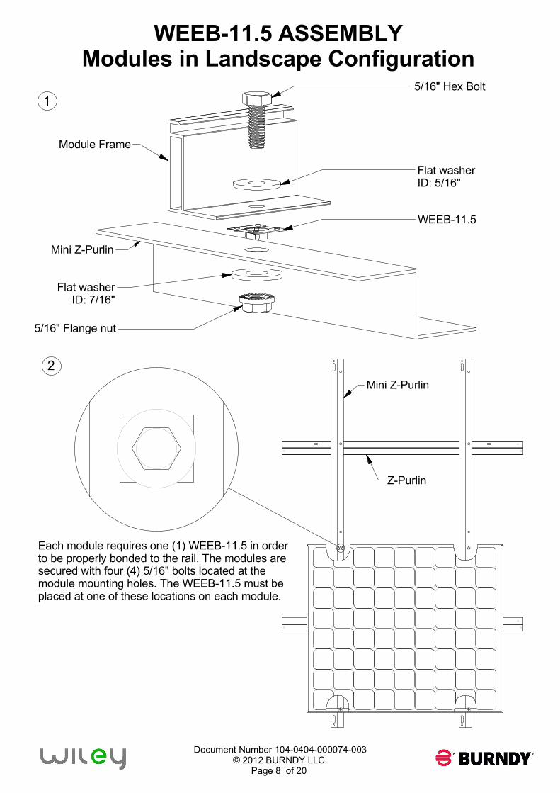
WEEB-11.5 ASSEMBLY
Modules in Landscape Configuration
Flat washer
ID: 5/16"
5/16" Flange nut
Flat washer
ID: 7/16"
Module Frame
5/16" Hex Bolt
Mini Z-Purlin
Z-Purlin
1
2
Each module requires one (1) WEEB-11.5 in order
to be properly bonded to the rail. The modules are
secured with four (4) 5/16" bolts located at the
module mounting holes. The WEEB-11.5 must be
placed at one of these locations on each module.
WEEB-11.5
Mini Z-Purlin
Document Number 104-0404-000074-003
© 2012 BURNDY LLC.
Page 9 of 20
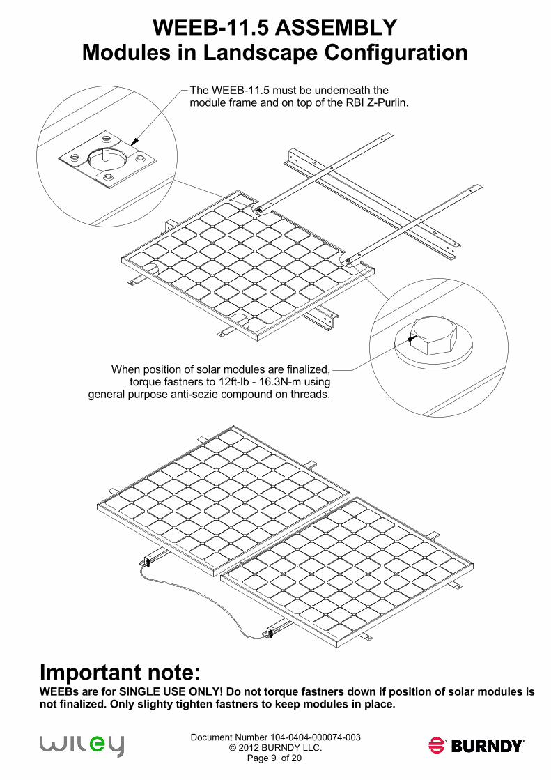
WEEB-11.5 ASSEMBLY
Modules in Landscape Configuration
Important note:
WEEBs are for SINGLE USE ONLY! Do not torque fastners down if position of solar modules is
not finalized. Only slighty tighten fastners to keep modules in place.
The WEEB-11.5 must be underneath the
module frame and on top of the RBI Z-Purlin.
When position of solar modules are finalized,
torque fastners to 12ft-lb - 16.3N-m using
general purpose anti-sezie compound on threads.
Document Number 104-0404-000074-003
© 2012 BURNDY LLC.
Page 10 of 20
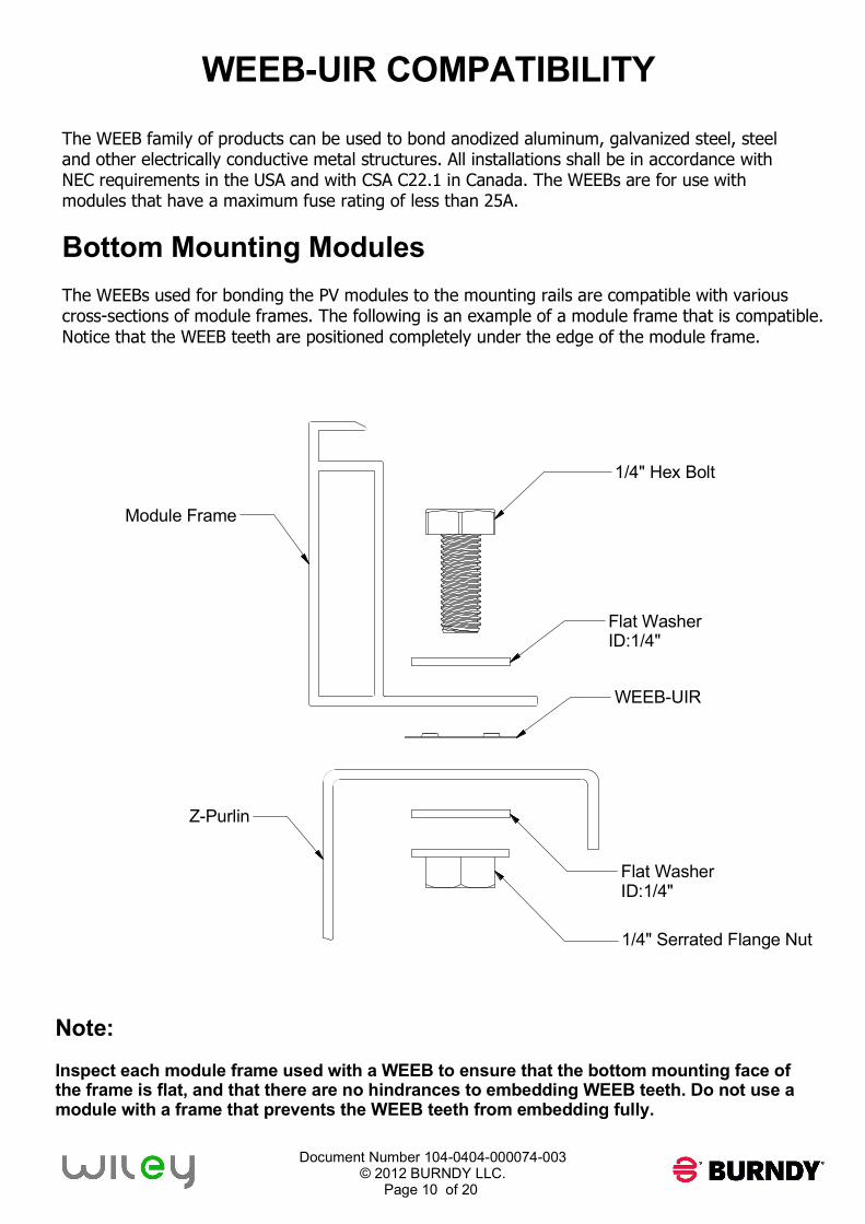
WEEB-UIR COMPATIBILITY
The WEEB family of products can be used to bond anodized aluminum, galvanized steel, steel
and other electrically conductive metal structures. All installations shall be in accordance with
NEC requirements in the USA and with CSA C22.1 in Canada. The WEEBs are for use with
modules that have a maximum fuse rating of less than 25A.
Bottom Mounting Modules
The WEEBs used for bonding the PV modules to the mounting rails are compatible with various
cross-sections of module frames. The following is an example of a module frame that is compatible.
Notice that the WEEB teeth are positioned completely under the edge of the module frame.
Note:
Inspect each module frame used with a WEEB to ensure that the bottom mounting face of
the frame is flat, and that there are no hindrances to embedding WEEB teeth. Do not use a
module with a frame that prevents the WEEB teeth from embedding fully.
1/4" Hex Bolt
Flat Washer
ID:1/4"
WEEB-UIR
Flat Washer
ID:1/4"
1/4" Serrated Flange Nut
Module Frame
Z-Purlin
Document Number 104-0404-000074-003
© 2012 BURNDY LLC.
Page 11 of 20
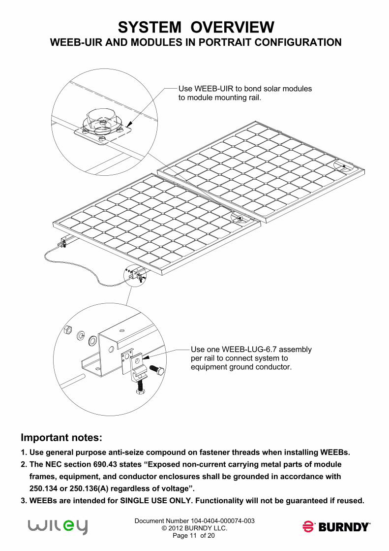
SYSTEM OVERVIEW
WEEB-UIR AND MODULES IN PORTRAIT CONFIGURATION
Important notes:
1. Use general purpose anti-seize compound on fastener threads when installing WEEBs.
2. The NEC section 690.43 states “Exposed non-current carrying metal parts of module
frames, equipment, and conductor enclosures shall be grounded in accordance with
250.134 or 250.136(A) regardless of voltage”.
3. WEEBs are intended for SINGLE USE ONLY. Functionality will not be guaranteed if reused.
Use WEEB-UIR to bond solar modules
to module mounting rail.
Use one WEEB-LUG-6.7 assembly
per rail to connect system to
equipment ground conductor.
Document Number 104-0404-000074-003
© 2012 BURNDY LLC.
Page 12 of 20
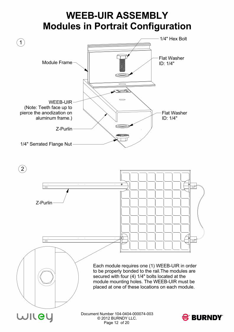
WEEB-UIR ASSEMBLY
Modules in Portrait Configuration
1/4" Serrated Flange Nut
WEEB-UIR
(Note: Teeth face up to
pierce the anodization on
aluminum frame.)
Module Frame
Z-Purlin
1
2
Each module requires one (1) WEEB-UIR in order
to be properly bonded to the rail.The modules are
secured with four (4) 1/4" bolts located at the
module mounting holes. The WEEB-UIR must be
placed at one of these locations on each module.
Flat Washer
ID: 1/4"
Flat Washer
ID: 1/4"
Z-Purlin
1/4" Hex Bolt
Document Number 104-0404-000074-003
© 2012 BURNDY LLC.
Page 13 of 20
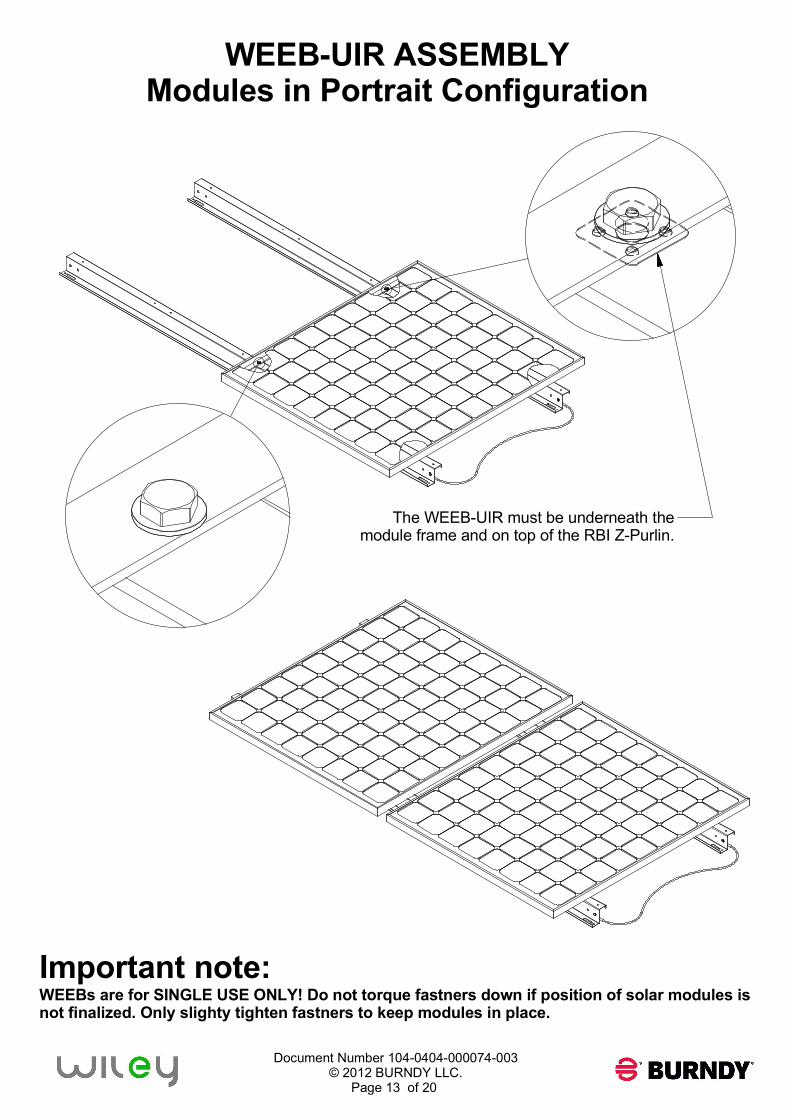
WEEB-UIR ASSEMBLY
Modules in Portrait Configuration
The WEEB-UIR must be underneath the
module frame and on top of the RBI Z-Purlin.
Important note:
WEEBs are for SINGLE USE ONLY! Do not torque fastners down if position of solar modules is
not finalized. Only slighty tighten fastners to keep modules in place.
Document Number 104-0404-000074-003
© 2012 BURNDY LLC.
Page 14 of 20
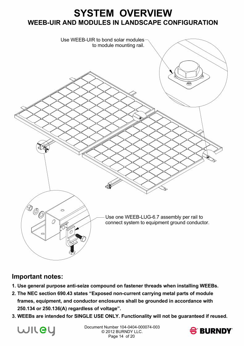
SYSTEM OVERVIEW
WEEB-UIR AND MODULES IN LANDSCAPE CONFIGURATION
Important notes:
1. Use general purpose anti-seize compound on fastener threads when installing WEEBs.
2. The NEC section 690.43 states “Exposed non-current carrying metal parts of module
frames, equipment, and conductor enclosures shall be grounded in accordance with
250.134 or 250.136(A) regardless of voltage”.
3. WEEBs are intended for SINGLE USE ONLY. Functionality will not be guaranteed if reused.
Use WEEB-UIR to bond solar modules
to module mounting rail.
Use one WEEB-LUG-6.7 assembly per rail to
connect system to equipment ground conductor.
Document Number 104-0404-000074-003
© 2012 BURNDY LLC.
Page 15 of 20
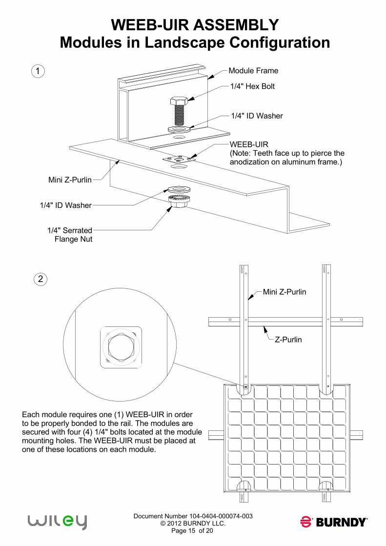
WEEB-UIR ASSEMBLY
Modules in Landscape Configuration
Module Frame
1/4" Hex Bolt
WEEB-UIR
(Note: Teeth face up to pierce the
anodization on aluminum frame.)
1/4" Serrated
Flange Nut
Mini Z-Purlin
Z-Purlin
1
2
Each module requires one (1) WEEB-UIR in order
to be properly bonded to the rail. The modules are
secured with four (4) 1/4" bolts located at the module
mounting holes. The WEEB-UIR must be placed at
one of these locations on each module.
Mini Z-Purlin
1/4" ID Washer
1/4" ID Washer
Document Number 104-0404-000074-003
© 2012 BURNDY LLC.
Page 16 of 20
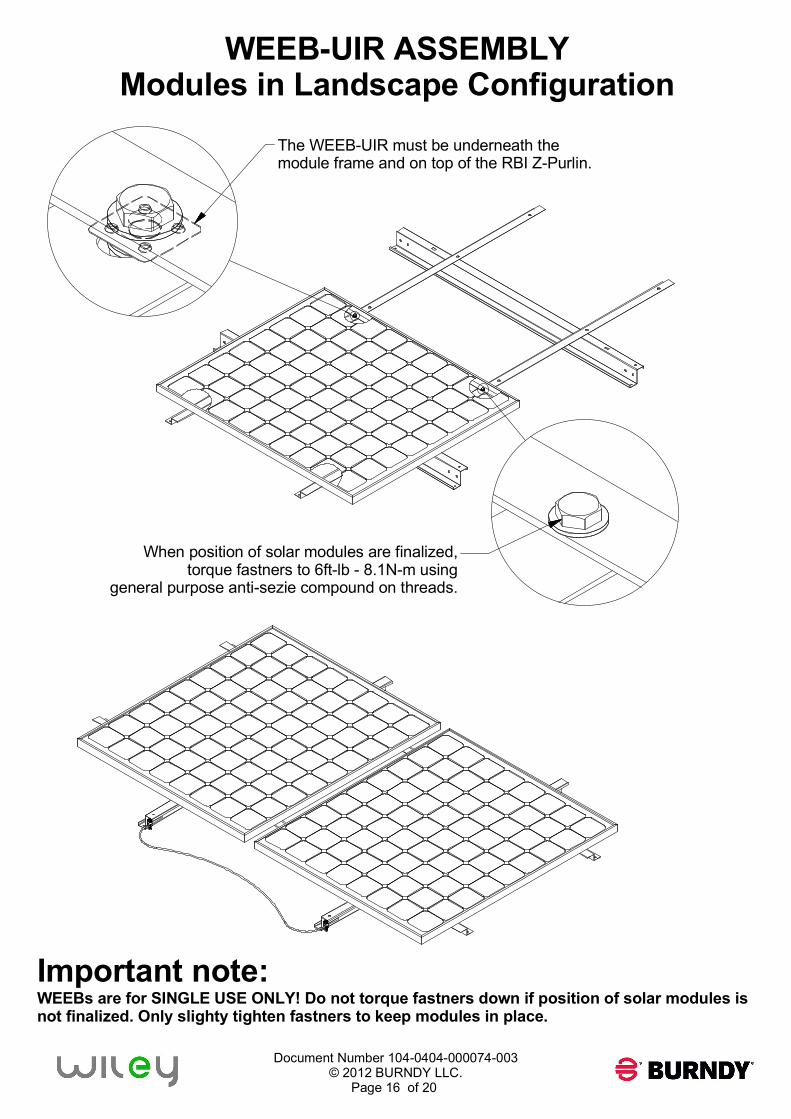
WEEB-UIR ASSEMBLY
Modules in Landscape Configuration
The WEEB-UIR must be underneath the
module frame and on top of the RBI Z-Purlin.
Important note:
WEEBs are for SINGLE USE ONLY! Do not torque fastners down if position of solar modules is
not finalized. Only slighty tighten fastners to keep modules in place.
When position of solar modules are finalized,
torque fastners to 6ft-lb - 8.1N-m using
general purpose anti-sezie compound on threads.
Document Number 104-0404-000074-003
© 2012 BURNDY LLC.
Page 17 of 20
X X XX
X X XXX
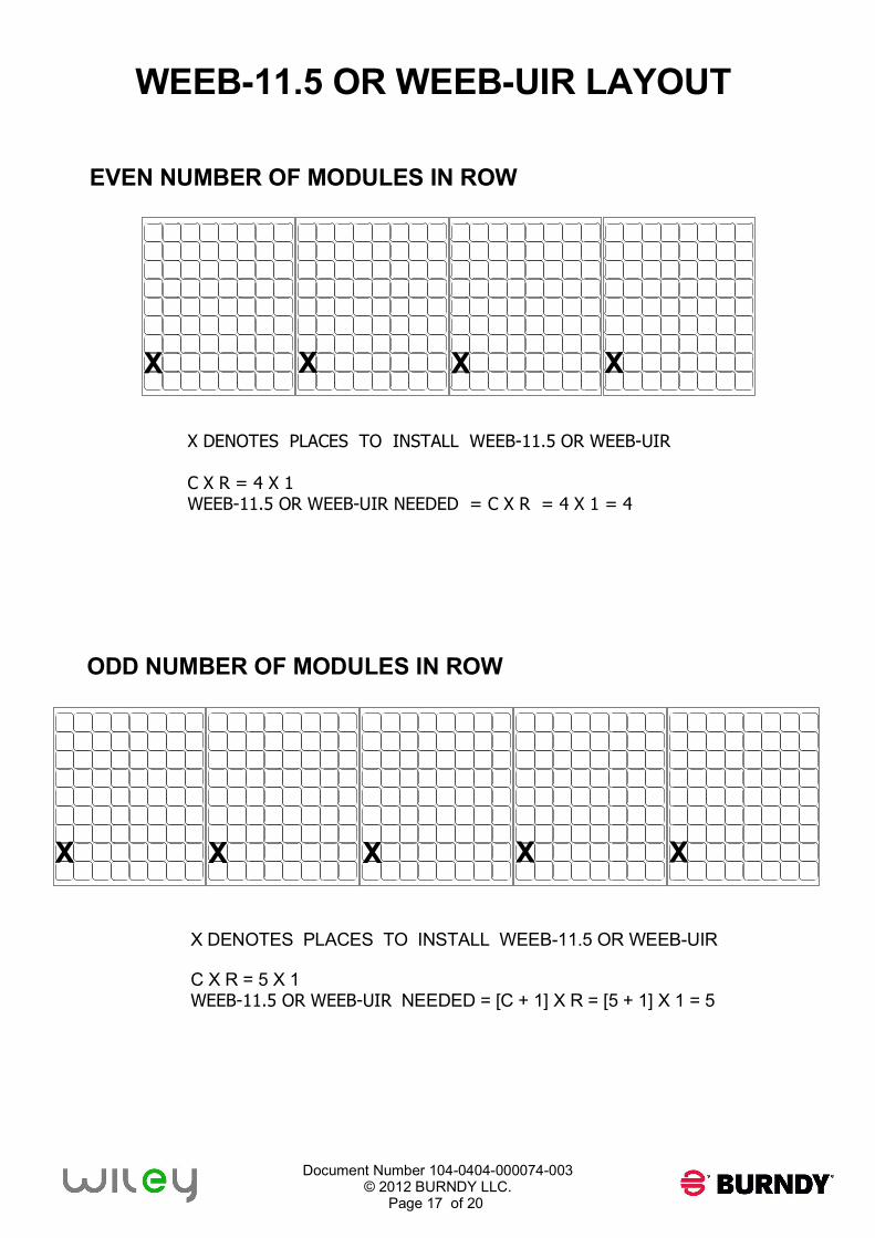
WEEB-11.5 OR WEEB-UIR LAYOUT
EVEN NUMBER OF MODULES IN ROW
X DENOTES PLACES TO INSTALL WEEB-11.5 OR WEEB-UIR
C X R = 4 X 1
WEEB-11.5 OR WEEB-UIR NEEDED = C X R = 4 X 1 = 4
ODD NUMBER OF MODULES IN ROW
X DENOTES PLACES TO INSTALL WEEB-11.5 OR WEEB-UIR
C X R = 5 X 1
WEEB-11.5 OR WEEB-UIR NEEDED = [C + 1] X R = [5 + 1] X 1 = 5
Document Number 104-0404-000074-003
© 2012 BURNDY LLC.
Page 18 of 20
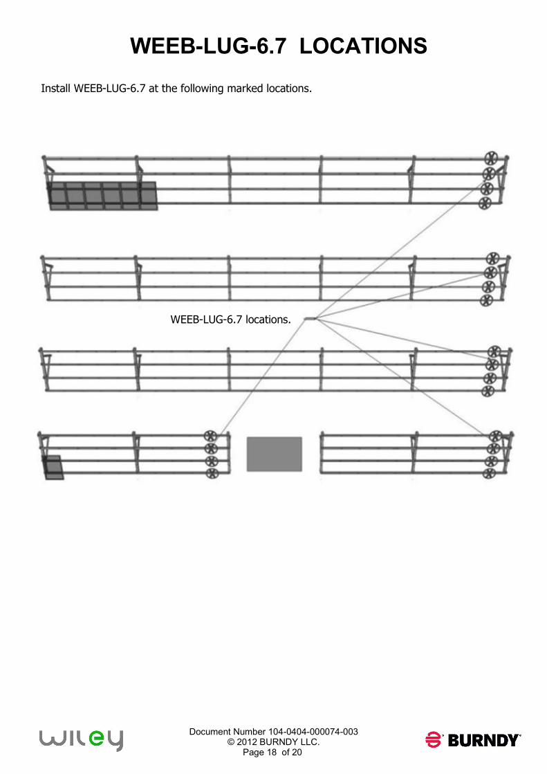
WEEB-LUG-6.7 LOCATIONS
Install WEEB-LUG-6.7 at the following marked locations.
WEEB-LUG-6.7 locations.
Document Number 104-0404-000074-003
© 2012 BURNDY LLC.
Page 19 of 20
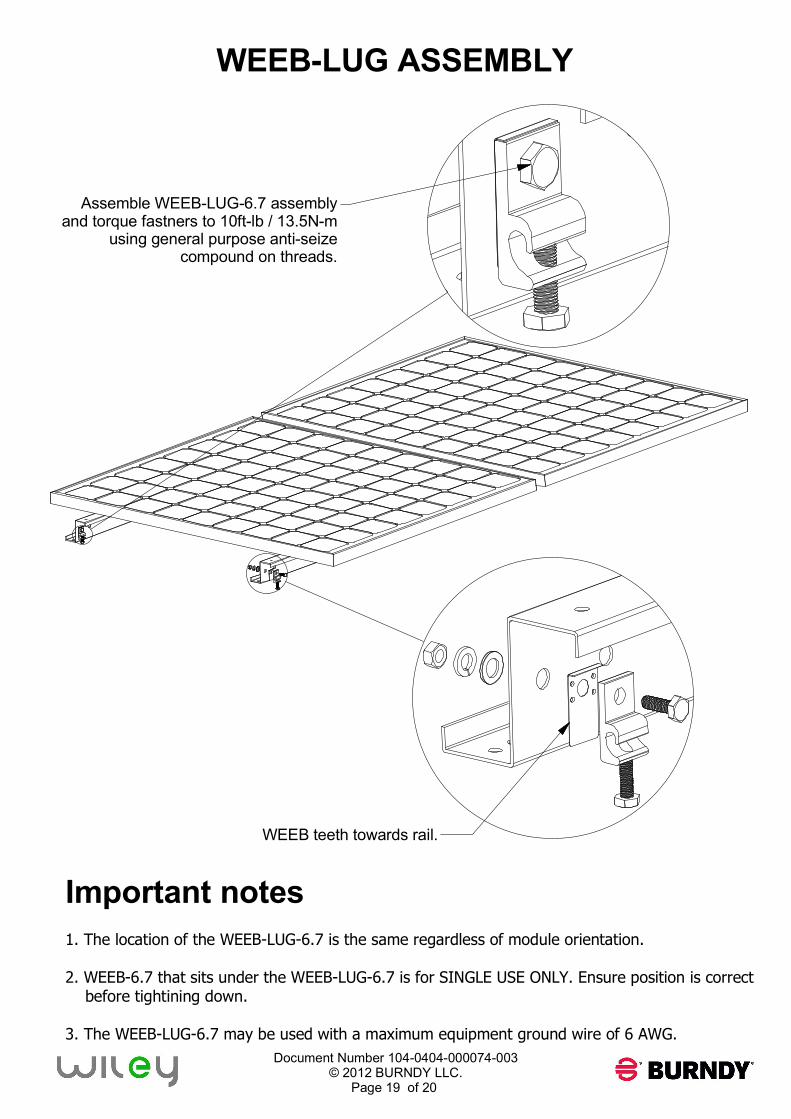
WEEB-LUG ASSEMBLY
Important notes
1. The location of the WEEB-LUG-6.7 is the same regardless of module orientation.
2. WEEB-6.7 that sits under the WEEB-LUG-6.7 is for SINGLE USE ONLY. Ensure position is correct
before tightining down.
3. The WEEB-LUG-6.7 may be used with a maximum equipment ground wire of 6 AWG.
Assemble WEEB-LUG-6.7 assembly
and torque fastners to 10ft-lb / 13.5N-m
using general purpose anti-seize
compound on threads.
WEEB teeth towards rail.
Document Number 104-0404-000074-003
© 2012 BURNDY LLC.
Page 20 of 20
Customer Service Department
7 Aviation Park Drive
Londonderry, NH 03053
1-800-346-4175
1-603-647-5299 (International)
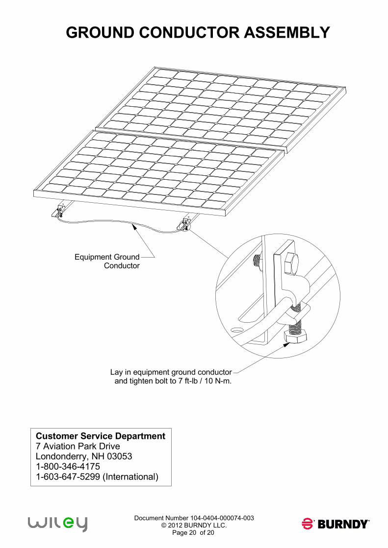
GROUND CONDUCTOR ASSEMBLY
Equipment Ground
Conductor
Lay in equipment ground conductor
and tighten bolt to 7 ft-lb / 10 N-m.