
Warwickshire County Council Wellesbourne Primary School ...
81
www.wyg.com creative minds safe hands Warwickshire County Council Wellesbourne Primary School Annexe Plant Noise Assessment April 2019 Executive Park, Avalon Way, Anstey, Leicester, LE7 7GR Tel: +44 (0)116 234 8000 Email: [email protected]
Transcript of Warwickshire County Council Wellesbourne Primary School ...

www.wyg.com creative minds safe hands
Warwickshire County Council
Wellesbourne Primary School Annexe
Plant Noise Assessment
April 2019
Executive Park, Avalon Way, Anstey, Leicester, LE7 7GR
Tel: +44 (0)116 234 8000
Email: [email protected]

www.wyg.com creative minds safe hands
Document Control
Project: Wellesbourne Primary School
Client: Warwickshire County Council
Job Number: A112162
File Origin: O:\Acoustics Air Quality and Noise\Active Projects\A112162
Document Checking:
Prepared by: Emma Aspinall Environmental Consultant
Initialled: EA
Checked by: Lewis Kelter AMIOA Environmental Consultant
Initialled: LK
Verified by: Nigel Mann MIOA
Director Initialled: NM
Issue Date Status
1 08th February 2019 First Issue
2 15th April 2019 Second Issue – Includes Updated Plant Detail and Mitigation following
consultation responses
3
4

www.wyg.com creative minds safe hands
Contents Page
1.0 Introduction.................................................................................................................................. 1
2.0 Assessment Criteria ....................................................................................................................... 4
3.0 Assessment Methodology .............................................................................................................. 5
4.0 Noise Survey ................................................................................................................................ 9
5.0 Assessment of Key Effects ........................................................................................................... 12
6.0 Conclusions ................................................................................................................................ 13
Appendix Contents
Appendix A – Acoustic Terminology and Abbreviations
Appendix B – Sketches
Appendix C – Manufacturer's Plant Data
Appendix D – Report Conditions
Appendix E – Comments Response to EHO - 20th February 2019
Appendix F – Comments Response to EHO - 07th March 2019

Noise Assessment
Warwickshire County Council 1 A112162
Wellesbourne Primary School April 2019
1.0 Introduction
1.1 Purpose of this Report
This report presents the finding of a noise assessment undertaken for the new building services plant
associated with the proposed extension at Wellesbourne Primary School Annexe, Warwickshire. This version
of the report incorporates revised plant and mitigation details and includes copies of correspondence received
from local Environmental Health Officers (EHO) for reference.
A description of the existing noise environment in and around the site is provided. Noise surveys have been
undertaken and the results used to verify predictions of the short-term and long-term effects of noise. The
noise levels from the proposed development have been predicted at local representative receptors using
CADNA noise modelling software which incorporates ISO 9613 methodologies and calculations.
A list of acoustic terminology and abbreviations used in this report is provided in Appendix A and a set of
location plans and noise contour plots are presented in Appendix B.
1.2 Legislative Context (England)
This report is intended to provide information relevant to the local planning authority and their consultees
in support of a planning application for the above proposed development. Policy guidance with respect to
noise is found in National Planning Policy Framework (NPPF), published on 19th February 2019. With
regard to noise and planning, NPPF contains the following statement at paragraph 170:
“170. Planning policies and decisions should contribute to and enhance the natural and local
environment by:
e) preventing new and existing development from contributing to, being put at unacceptable risk
from, or being adversely affected by, unacceptable levels of soil, air, water or noise pollution or
land instability. Development should, wherever possible, help to improve local environmental
conditions such as air and water quality, taking into account relevant information such as river
basin management plans
A further 2 short statements are presented at paragraph 180, which state:
“180. Planning policies and decisions should also ensure that new development is appropriate for its
location taking into account the likely effects (including cumulative effects) of pollution on health, living
conditions and the natural environment, as well as the potential sensitivity of the site or the wider area
to impacts that could arise from the development. In doing so they should:

Noise Assessment
Warwickshire County Council 2 A112162
Wellesbourne Primary School April 2019
a) “mitigate and reduce to a minimum potential adverse impacts resulting from noise from new
development – and avoid noise giving rise to significant adverse impacts on health and the quality
of life
b) identify and protect tranquil areas which have remained relatively undisturbed by noise and are
prized for their recreational and amenity value for this reason.”
Furthermore, paragraphs 182 and 183 state:
“182. Planning policies and decisions should ensure that new development can be integrated
effectively with existing businesses and community facilities (such as places of worship, pubs,
music venues and sports clubs). Existing businesses and facilities should not have unreasonable
restrictions placed on them as a result of development permitted after they were established.
Where the operation of an existing business or community facility could have a significant adverse
effect on new development (including changes of use) in its vicinity, the applicant (or ‘agent of
change’) should be required to provide suitable mitigation before the development has been
completed.
183. The focus of planning policies and decisions should be on whether proposed development
is an acceptable use of land, rather than the control of processes or emissions (where these are
subject to separate pollution control regimes). Planning decisions should assume that these
regimes will operate effectively. Equally, where a planning decision has been made on a particular
development, the planning issues should not be revisited through the permitting regimes operated
by pollution control authorities.”
Planning Practice Guidance (PPG): Noise provides further guidance with regard to the assessment of noise
within the context of Planning Policy. The overall aim of this guidance is, tying in with the principles of the
NPPF and the Explanatory Note of the Noise Policy Statement for England, is to, 'identify whether the
overall effect of noise exposure is, or would be, above or below the significant observed adverse effect
level and the lowest observed adverse effect level for the given situation.’
A summary of the effects of noise exposure associated with both noise generating developments and noise
sensitive developments is presented within the PPG and repeated as follows:

Noise Assessment
Warwickshire County Council 3 A112162
Wellesbourne Primary School April 2019
Table 1.1 Noise Exposure Hierarchy
Perception Examples of Outcomes Increasing Effect Level Action
Not noticeable No Effect No Observed Effect No Specific Measures
Required
Noticeable and not intrusive
Noise can be heard but does not cause any change in behaviour or attitude. Can slightly affect the acoustic character of the area but not such that there is a
perceived change in the quality of life.
No Observed Adverse Effect (NOAEL)
No Specific Measures Required
Lowest Observed Adverse Effect Level (LOAEL)
Noticeable and intrusive
Noise can be heard and causes small changes in behaviour and/or attitude, e.g. turning up volume of television;
speaking more loudly; closing windows for some of the time because of the
noise. Potential for non-awakening sleep disturbance. Affects the acoustic
character of the area such that there is a perceived change in the quality of life.
Observed Adverse Effect Mitigate and reduce to a
minimum
Significant Observed Adverse Effect Level (SOAEL)
Noticeable and disruptive
The noise causes a material change in behaviour and/or attitude, e.g. having to keep windows closed most of the time, avoiding certain activities during periods
of intrusion. Potential for sleep disturbance resulting in difficulty in
getting to sleep, premature awakening and difficulty in getting back to sleep.
Quality of life diminished due to change in acoustic character of the area.
Significant Observed Adverse Effect
Avoid
Noticeable and very disruptive
Extensive and regular changes in behaviour and/or an inability to mitigate effect of noise leading to psychological
stress or physiological effects, e.g. regular sleep deprivation/awakening; loss
of appetite, significant, medically definable harm, e.g. auditory and non-
auditory
Unacceptable Observed Adverse Effect
Prevent

Noise Assessment
Warwickshire County Council 4 A112162
Wellesbourne Primary School April 2019
2.0 Assessment Criteria
In order to enable the assessment of the proposed plant in terms of LOAEL and SOAEL, Table 2.1 presents
equivalent noise levels and associated actions with the target noise level criteria identified. The noise level
criteria detailed below have been derived from standard and design guidance:
BS 4142:2014, ‘Methods for rating and assessing industrial and commercial sound’
Table 2.1 Noise Level Criteria and Actions
Effect Level Assessment Noise Level Criteria Action / Justification
No Observed Adverse
Effect Level
Building Services Plant
Source noise levels below background LA90
noise levels
No Action Required Source noise levels below the
background noise is an indication of the sound source having a low impact and
that complaints would be unlikely
Lowest Observed Adverse
Effect Level (LOAEL)
Difference between source noise levels and existing background levels of zero to 5 dB
Action: None Justification: + 5 dB above background is considered an indication of an impact
of marginal significance.
Significant Observed Adverse
Effect Level (SOAEL)
Difference between source noise levels and existing background levels of 5 to 10 dB
Action: Mitigate to achieve less than 5dB
above background if possible:
Justification: Depending on context, a difference of +10dB to be an indication
that complaints are likely.
Unacceptable Observed Adverse
Effect Level (UOAEL)
Difference between source noise levels and existing background levels of greater
than 10 dB
Action: Reduce as far as practicable depending on context
Justification: +10dB above existing
background is an indication of a likely significant adverse impact
Noise Assessment
Warwickshire County Council 5 A112162
Wellesbourne Primary School April 2019
3.0 Assessment Methodology
3.1 Noise Modelling Methodology
With regard to an assessment of building services plant, three-dimensional noise modelling has been
undertaken based on the monitoring data to predict source noise levels at a large number of locations both
horizontally and vertically. CADNA noise modelling software has been used. This model is based on ISO 9613
noise propagation methodology.
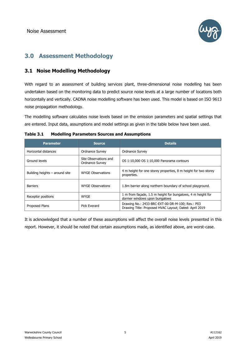
The modelling software calculates noise levels based on the emission parameters and spatial settings that
are entered. Input data, assumptions and model settings as given in the table below have been used.
Table 3.1 Modelling Parameters Sources and Assumptions
Parameter Source Details
Horizontal distances Ordnance Survey Ordnance Survey
Ground levels Site Observations and Ordnance Survey
OS 1:10,000 OS 1:10,000 Panorama contours
Building heights – around site WYGE Observations 4 m height for one storey properties, 8 m height for two storey properties.
Barriers WYGE Observations 1.8m barrier along northern boundary of school playground.
Receptor positions WYGE 1 m from façade, 1.5 m height for bungalows, 4 m height for dormer windows upon bungalows
Proposed Plans Pick Everard Drawing No.: 2433-BRC-EXT-00-DR-M-100; Rev.: P03 Drawing Title: Proposed HVAC Layout; Dated: April 2019
It is acknowledged that a number of these assumptions will affect the overall noise levels presented in this
report. However, it should be noted that certain assumptions made, as identified above, are worst-case.

Noise Assessment
Warwickshire County Council 6 A112162
Wellesbourne Primary School April 2019
3.2 Model Input Data
3.2.1 Building Services Plant (BSP) Noise Data
It is understood that one Air Handling Unit (AHU) within an enclosed plant room and two air intake louvres
are to be installed to the southeast of the proposed extension. Two heating, ventilation, and air conditioning
(HVAC) units and two exhaust louvres are to be installed along the northern margin of the proposed
extension. The location of the proposed BSP is shown on SK02 of Appendix B. A vertical area source has
been input into the model to represent AHU breakout from the enclosed plant room and louvre breakout
and two point sources are used to represent the proposed HVAC units; manufacturers’ details of the
proposed plant are presented in Table 3.2 below.
Table 3.2 Plant Noise Levels
Description Sound Power Level (dBA)
1 x Swegon Gold F-20-AD-1000499735 (AHU) 74
2 x Air Intake Louvre 66
2 x Exhaust Louvre 81
1 x Epsilon Echos HP 31 (HVAC) 76
1 x PUHZ-ZRP200YKA (HVAC) 62
No insertion loss has been applied to the air intake and exhaust louvres, therefore representing a worst-
case scenario.
Table 3.3 below presents the calculated internal reverberant noise level of the AHU room based on worst-
case assumptions, using A-weighted sound power data from the exhaust air (74 dB) of the Swegon Gold F-
20-AD-10000499735.
Table 3.3 Calculated Reverberant Noise Level for AHU Plant Room
BSP Unit 63 125 250 500 1K 2K 4K 8K
Length 3.0 3.0 3.0 3.0 3.0 3.0 3.0 3.0
Width 1.4 1.4 1.4 1.4 1.4 1.4 1.4 1.4
Height 1.7 1.7 1.7 1.7 1.7 1.7 1.7 1.7
RT 1.5 1.5 1.5 1.5 1.5 1.5 1.5 1.5
r distance from source to nearest internal facade
1 1 1 1 1 1 1 1
Q Directivity 4 4 4 4 4 4 4 4

Noise Assessment
Warwickshire County Council 7 A112162
Wellesbourne Primary School April 2019
BSP Unit 63 125 250 500 1K 2K 4K 8K
Lw 45.8 50.9 60.4 67.8 68.0 68.2 66.0 63.9
Volume of Space 7.1 7.1 7.1 7.1 7.1 7.1 7.1 7.1
Surface Areas 23.4 23.4 23.4 23.4 23.4 23.4 23.4 23.4
A Total Absorption 0.8 0.8 0.8 0.8 0.8 0.8 0.8 0.8
Alpha bar 0.7 0.7 0.7 0.7 0.7 0.7 0.7 0.7
Rc Room Constant 54.5 54.5 54.5 54.5 54.5 54.5 54.5 54.5
SPL 42 47 56 64 64 64 62 60
Calculated Reverberant SPL Based on Number
of Sources
42.0 47.0 56.0 64.0 64.0 64.0 62.0 60.0
Sound Pressure Level 70.2
It has been confirmed that a 300mm deep Sound Block Louvre System (Metador Defender Soundguard –
acoustic louvre doors) is to be installed at the enclosed plant room. This provides a sound reduction of Rw
18 dB. With this attenuation, the output from the AHU plant room with the above reverberant calculations
is 52.2 dB (A).
3.2.2 Building Services Plant (BSP) Operating Conditions
Clarifications from the mechanical engineer regarding the hours of operation and conditions of the plant
have been sought, with the response detailed below:
“General hours of operation for the AHU and AC plant will be as per the normal school hours, allowing for
teaching staff arriving prior to the start of the school day and cleaning staff afterwards – typically 8:00am
to 6:00pm. We would not anticipate HVAC plant to be running for any more than 1 hour each side of these
times to allow for heat-up / cool down.
With regard to frost protection, we have not specified this function, but in any case if such function were
included, running noise levels would be no higher than normal operation.
With regard to defrost mode, this is an automatic function of the specified air-source heat pumps /
condensers. Whilst this function can activate automatically, it would only do so when the units are already
running, within the time range referred to above. Again, running noise levels will be no higher as the units
just goes into reverse mode / cycle.
Finally, regarding the kitchen equipment & extract, this would generally be limited to late morning to
lunchtime.”
As detailed above, the worst-case proposed hours of operation would be between 07:00-19:00 during
weekday periods. Therefore, only daytime hours have been considered within this report.

Noise Assessment
Warwickshire County Council 8 A112162
Wellesbourne Primary School April 2019
3.3 Sensitive Receptors
The table below summarises receptor locations that have been selected to represent worst-case noise
sensitive receptors with respect to direct noise from the proposed plant. As the surrounding properties are
predominantly bungalows, ground floors of the nearest noise sensitive properties have been presented with
the locations of receptors shown on SK02 in Appendix B. The closest gardens with respect to plant noise
have also been assessed.
Table 3.4 Sensitive Receptor Locations
Ref. Description Height (m)
Daytime
R01 60 Mountford Close 1.5
R02 62 Mountford Close 1.5
R03 64 Mountford Close 1.5
R04 66 Mountford Close 1.5
R05 68 Mountford Close 1.5
R06 70 Mountford Close 1.5
R07 72 Mountford Close 1.5
R08 74 Mountford Close 1.5
R09 76 Mountford Close 1.5
R10 78 Mountford Close 1.5
R11 80 Mountford Close 1.5
G01 Garden at 70 Mountford Close 1.2
G02 Garden at 68 Mountford Close 1.2

Noise Assessment
Warwickshire County Council 9 A112162
Wellesbourne Primary School April 2019
4.0 Noise Survey
4.1 Noise Survey Methodology
A monitoring survey was undertaken to characterise baseline ambient noise levels currently experienced on
the site and to establish the relative local background and traffic noise levels. Equipment used during the
survey included:
Rion NL-52 Environmental Noise Analyser s/n 253701
Rion NL-52 Environmental Noise Analyser s/n 342867
Rion NC-74 Sound Calibrator s/n 35046823
The measurement equipment was checked against the appropriate calibrator at the beginning and end of
the measurements, in accordance with recommended practice, a drift of 0.1 dB was observed. The accuracy
of the calibrators can be traced to National Physical Laboratory Standards, calibration certificates for which
are available on request.
A baseline monitoring survey was undertaken at five locations (as specified in the following table and shown
in SK01 of Appendix B) from Friday 18th January 2019 to Wednesday 23rd January 2019. Attended short term
measurements were undertaken at three locations during day and evening periods with two additional
locations being measured unattended over a 120-hour period. The raw data collected from the long-term
monitoring is available upon request.
Measurements were taken in general accordance with BS 7445-1:2003 The Description and Measurement of
Environmental Noise: Guide to quantities and procedures. Weather conditions during the survey period were
observed as being dry. Anemometer readings confirmed that wind speeds were less than 5 ms-1 at all times
during the survey, with a predominant westerly wind direction during the survey.
Table 4.1 Noise Monitoring Locations
Ref Description
LT1 Northwest corner of the site
LT2 Southeast corner of the site
ST1 South of the site, Mountford Close
ST2 Site access road
ST3 West of the site, Newbold Road
4.2 Noise Survey Results
The ambient noise climate of the area includes road traffic noise from Newbold Road and the A429, as well
as occasional aircraft noise.

Noise Assessment
Warwickshire County Council 10 A112162
Wellesbourne Primary School April 2019
Ambient and background noise levels are usually described using the LAeq index (a form of energy average)
and the LA90 index (i.e. the level exceeded for 90% of the measurement period) respectively. Road traffic
noise is generally described using the LA10 index (i.e. the level exceeded for 10% of the measurement period).
For the long-term (LT) locations, the presented LAeq,T and LA10,T are average noise levels whilst the LA90 is the
modal noise level of each 5 minute measurement over the stated survey period.
Table 4.2 Meteorological Conditions during the Survey
Survey
Location Date & Time
Temperature
(ºC)
Wind Speed
(m/s)
Wind
Direction
Cloud Cover
(Oktas) Dominant Noise Source
Daytime ST1
23/01/2019 09:42
0 0 - 0 Distant road traffic noise
from Newbold Road,
Daytime ST2
23/01/2019 10:26
0 0 - 0 Distant road traffic noise
from Newbold Road
Daytime ST3
23/01/2019 10:05
0 0 - 0 Road traffic noise Newbold
Road
Evening ST1
23/01/2019 19:57
1 0 - 1 W 4 Distant road traffic from
Newbold Road, occasional aircraft and passing cars
Evening ST2
23/01/2019 19:32
1 0 - 1 W 4 Distant road traffic from
Newbold Road, occasional aircraft
Evening ST3
23/01/2019 19:12
1 0 - 1 W 5 Road traffic noise Newbold
Road
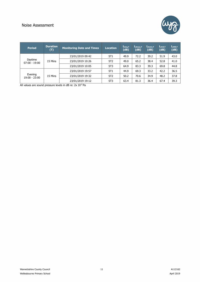
The results of the statistical measurements and frequency measurements conducted during the survey are
summarised in the following table. All values are sound pressure levels in dB (re: 2 x 10⁻⁵ Pa).
Table 4.3 Results of Baseline Noise Monitoring Survey (Average Levels)
Period Duration
(T) Monitoring Date and Times Location
LAeq,T (dB)
LAmax,T (dB)
LAmin,T (dB)
LA10,T (dB)
LA90,T (dB)
Weekday Daytime
07:00 - 23:00 48 Hours
18/01/2019 – 23/01/2019 11:27 – 10:52
LT1
61.7 99.3 25.1 54.1 42.0
Weekday Night-time
23:00 – 07:00 24 Hours
18/01/2019 – 23/01/2019 23:00 – 07:00
45.9 79.9 24.3 40.7 33.0
Weekend Daytime
07:00 - 23:00 32 Hours
19/01/2019 – 20/01/2019 07:00 – 23:00
50.7 91.5 19.9 46.9 36.0
Weekend Night-time
23:00 – 07:00 16 hours
19/01/2019 – 20/01/2019 23:00 – 07:00
41.0 68.7 16.0 37.3 28.0
Weekday Daytime
07:00 - 23:00 48 Hours
18/01/2019 – 23/01/2019 11:07 – 10:42
LT2
52.7 88.1 24.7 50.6 42.0
Weekday Night-time
23:00 – 07:00 24 Hours
18/01/2019 – 23/01/2019 23:00 – 07:00
44.1 75.9 23.5 42.7 34.0
Weekend Daytime
07:00 - 23:00 32 Hours
19/01/2019 – 20/01/2019 07:00 – 23:00
49.9 91.8 19.6 46.5 40.0
Weekend Night-time
23:00 – 07:00 16 hours
19/01/2019 – 20/01/2019 23:00 – 07:00
38.0 64.7 16.2 36.1 18.0
Noise Assessment
Warwickshire County Council 11 A112162
Wellesbourne Primary School April 2019
Period Duration
(T) Monitoring Date and Times Location
LAeq,T (dB)
LAmax,T (dB)
LAmin,T (dB)
LA10,T (dB)
LA90,T (dB)
Daytime 07:00 - 19:00
15 Mins
23/01/2019 09:42 ST1 49.9 72.2 39.2 51.9 43.0
23/01/2019 10:26 ST2 49.0 65.2 38.4 52.8 41.0
23/01/2019 10:05 ST3 64.9 83.3 39.3 69.8 44.8
Evening 19:00 - 23:00
15 Mins
23/01/2019 19:57 ST1 44.9 69.3 33.2 42.2 36.5
23/01/2019 19:32 ST2 50.2 70.6 34.9 48.2 37.8
23/01/2019 19:12 ST3 63.4 81.3 36.4 67.4 39.3
All values are sound pressure levels in dB re: 2x 10⁻⁵ Pa

Noise Assessment
Warwickshire County Council 12 A112162
Wellesbourne Primary School April 2019
5.0 Assessment of Key Effects
5.1 BS 4142 Plant Noise Assessment
This assessment has been undertaken in order to establish the effect of noise from the proposed building
services plant and has been undertaken with the plant operating at full capacity during the daytime period.
The assessment incorporates a 2.0m high acoustic barrier along the southeast corner of the site. The location
of the barrier is illustratively shown on SK02 of Appendix B.
The assessment compares the predicted average noise rating levels from proposed plant with the measured
pre-installation daytime background noise LA90 at the nearest noise sensitive properties. A representative
daytime background LA90 noise level of 36 dB at the closest properties and 40 dB at the closest gardens have
been used. Based on the experience of the assessor of similar plant installations, it is not expected that the
plant would exhibit any tonal characteristics, however, to account for any potential tonal features of the plant
which may be just perceptible at sensitive receptors, an overall +2 dB correction has been applied in line
with section 9.2 of BS 4142:2014.
Table 5.1 Noise Assessment for Proposed BSP
Ref Measured Average
Pre-installation Background LA90
Specific noise level from plant LAeq
Noise Rating Level from Plant LAeq
BS 4142 Score
R01 36 27 29 -7
R02 36 28 30 -6
R03 36 28 30 -6
R04 36 28 30 -6
R05 36 29 31 -6
R06 36 25 27 -9
R07 36 22 24 -12
R08 36 20 22 -14
R09 36 18 20 -16
R10 36 15 17 -19
R11 36 14 16 -20
G01 40 32 34 -6
G02 40 34 36 -4
All values are sound pressure levels in dBA re: 2x 10⁻⁵ Pa.
All calculations used to derive the above tables (including averaging of background noise levels and predicted source noise levels) have
been undertaken to 1 decimal place to avoid perpetuation of rounding errors. However, in accordance with BS4142 Para 8.6, the levels
are expressed as integers (with 0.5 dB being rounded up). This may mean that the arithmetic in the above table may appear to be up
to 1 dB incorrect due to this rounding.
The assessment above shows that worst-case plant noise rating levels, with the inclusion of a 2.0m high
acoustic barrier are predicted to be at least 4 dB below background noise levels during the daytime period
at all nearby sensitive receptor locations, which is an indication that an adverse impact is unlikely.

Noise Assessment
Warwickshire County Council 13 A112162
Wellesbourne Primary School April 2019
6.0 Conclusions
This report presents the finding of a noise assessment undertaken for the new building services plant
associated with the proposed extension at Wellesbourne Primary School Annexe, Warwickshire. The NPPF
gives test points relating to noise; considering these the following conclusions can be drawn:
• NPPF paragraphs 170 (e) & 180 (a)
Rating noise levels from the new building services plant demonstrate that background noise levels will not
be exceeded at nearby noise sensitive receptors during the daytime with the inclusion of a 2.0m high acoustic
barrier. Therefore, the proposed plant is not expected to have a ‘significant adverse impact’ on health or
quality of life.
• NPPF paragraphs 180 (b), 182 & 183
The proposed building services plant is not expected to exceed background noise levels, nor have a significant
contribution to the ambient noise climate during the daytime. Therefore, it is considered that the proposed
plant would not restrict existing businesses whilst the tranquillity of the area, which is characterised by road
traffic noise, will not be to be affected.

Noise Assessment
Warwickshire County Council A112162
Wellesbourne Primary School April 2019
Appendices

Noise Assessment
Warwickshire County Council A112162
Wellesbourne Primary School April 2019
Appendix A – Acoustic Terminology and Abbreviations
An explanation of the specific acoustic terminology referred to within this report is provided below.
dB Sound levels from any source can be measured in frequency bands in order to provide detailed
information about the spectral content of the noise, i.e. whether it is high-pitched, low-pitched, or
with no distinct tonal character. These measurements are usually undertaken in octave or third
octave frequency bands. If these values are summed logarithmically, a single dB figure is obtained.
This is usually not very helpful as it simply describes the total amount of acoustic energy measured
and does not take any account of the ear’s ability to hear certain frequencies more readily than
others.
dB(A) Instead, the dBA figure is used, as this is found to relate better to the loudness of the sound heard.
The dBA figure is obtained by subtracting an appropriate correction, which represents the variation
in the ear’s ability to hear different frequencies, from the individual octave or third octave band
values, before summing them logarithmically. As a result the single dBA value provides a good
representation of how loud a sound is.
LAeq Since almost all sounds vary or fluctuate with time it is helpful, instead of having an instantaneous
value to describe the noise event, to have an average of the total acoustic energy experienced over
its duration. The LAeq, 07:00 – 23:00 for example, describes the equivalent continuous noise level over
the 12 hour period between 7 am and 11 pm. During this time period the LpA at any particular time
is likely to have been either greater or lower that the LAeq, 07:00 – 23:00.
LAmin The LAmin is the quietest instantaneous noise level. This is usually the quietest 125 milliseconds
measured during any given period of time.
LAmax The LAmax is the loudest instantaneous noise level. This is usually the loudest 125 milliseconds
measured during any given period of time.
Ln Another method of describing, with a single value, a noise level which varies over a given time
period is, instead of considering the average amount of acoustic energy, to consider the length of
time for which a particular noise level is exceeded. If a level of x dBA is exceeded for say. 6 minutes
within one hour, then that level can be described as being exceeded for 10% of the total
measurement period. This is denoted as the LA10, 1 hr = x dB.
The LA10 index is often used in the description of road traffic noise, whilst the LA90, the noise level
exceeded for 90% of the measurement period, is the usual descriptor for underlying background
noise. LA1 and LAmax are common descriptors of construction noise.
Rw The weighted sound reduction index determined using the above measurement procedure, but
weighted in accordance with the procedures set down in BS EN ISO 717-1. Partitioning and building
board manufacturers commonly use this index to describe the inherent sound insulation
performance of their products.

Noise Assessment
Warwickshire County Council A112162
Wellesbourne Primary School April 2019
An explanation of abbreviations used within this report is provided below.
CADNA – Computer Aided Noise Abatement
DMRB – Design Manual for Roads and Bridges
HGV – Heavy Goods Vehicle
PPG – Planning Practice Guidance
UDP – Unitary Development Plan
UKAS – United Kingdom Accreditation Service
WYGE – WYG Environment

Noise Assessment
Warwickshire County Council A112162
Wellesbourne Primary School April 2019
Appendix B – Sketches
SK01 Noise Monitoring Locations
SK02 Sensitive Receptor Locations, Proposed Extension, Plant and Barrier Location
SK03 Daytime LAeq Contribution from Proposed BSP

LT2
LT1
ST1
ST2
ST3
Newbold Road
Mountford Close
428160
428160
428180
428180
428200
428200
428220
428220
428240
428240
428260
428260
428280
428280
428300
428300
428320
428320
428340
428340
428360
428360
428380
428380
428400
428400
428420
428420
428440
428440
428460
428460
428480
428480
428500
428500
428520
428520
428540
428540
428560
428560
428580
4285802
55
42
0
25
54
20
25
54
40
25
54
40
25
54
60
25
54
60
25
54
80
25
54
80
25
55
00
25
55
00
25
55
20
25
55
20
25
55
40
25
55
40
25
55
60
25
55
60
25
55
80
25
55
80
25
56
00
25
56
00
25
56
20
25
56
20
25
56
40
25
56
40
25
56
60
25
56
60
25
56
80
25
56
80
25
57
00
25
57
00
25
57
20
25
57
20
25
57
40
25
57
40
Client:
Warwickshire CountyCouncil
Project:
Wellesbourne PrimarySchool
Project Number:
A112162
Drawing Title / Scenario:
Noise Monitoring Locations
Drawing Number:
SK01
Key:
Site Boundary:
Scale : Not to scale
WYGE Leicester 11.04.19
This map is based upon Ordnance Survey material reproducedby WYG on behalf of Her Majesty's Stationery Office, © Crown Copyright. Unauthorised reproduction infringesCrown copyright and may lead to civil proceedings.
Licence Number AL 553611
Executive ParkAvalon WayAnsteyLeicestershireLE7 7GRTel 0116 234 8000
© WYG Environment

Newbold Road
Mountford Close
HVAC Units
AHU
R01
R02
R03
R04
R05
R06
R07
R08
R09
R10
R11
G01
G02Intake Louvre
Intake Louvre
Exhaust Louvres
428160
428160
428180
428180
428200
428200
428220
428220
428240
428240
428260
428260
428280
428280
428300
428300
428320
428320
428340
428340
428360
428360
428380
428380
428400
428400
428420
428420
428440
428440
428460
428460
428480
428480
428500
428500
428520
428520
428540
428540
428560
428560
428580
4285802
55
42
0
25
54
20
25
54
40
25
54
40
25
54
60
25
54
60
25
54
80
25
54
80
25
55
00
25
55
00
25
55
20
25
55
20
25
55
40
25
55
40
25
55
60
25
55
60
25
55
80
25
55
80
25
56
00
25
56
00
25
56
20
25
56
20
25
56
40
25
56
40
25
56
60
25
56
60
25
56
80
25
56
80
25
57
00
25
57
00
25
57
20
25
57
20
25
57
40
25
57
40
Client:
Warwickshire CountyCouncil
Project:
Wellesbourne PrimarySchool
Project Number:
A112162
Drawing Title / Scenario:
Sensitive ReceptorLocations, ProposedExtension, Plant andBarrier Location
Drawing Number:
SK02
Key:
Site Boundary:
2.0m AcousticBarrier:
Scale : Not to scale
WYGE Leicester 12.04.19
This map is based upon Ordnance Survey material reproducedby WYG on behalf of Her Majesty's Stationery Office, © Crown Copyright. Unauthorised reproduction infringesCrown copyright and may lead to civil proceedings.
Licence Number AL 553611
Executive ParkAvalon WayAnsteyLeicestershireLE7 7GRTel 0116 234 8000
© WYG Environment

428160
428160
428180
428180
428200
428200
428220
428220
428240
428240
428260
428260
428280
428280
428300
428300
428320
428320
428340
428340
428360
428360
428380
428380
428400
428400
428420
428420
428440
428440
428460
428460
428480
428480
428500
428500
428520
428520
428540
428540
428560
428560
428580
4285802
55
42
0
25
54
20
25
54
40
25
54
40
25
54
60
25
54
60
25
54
80
25
54
80
25
55
00
25
55
00
25
55
20
25
55
20
25
55
40
25
55
40
25
55
60
25
55
60
25
55
80
25
55
80
25
56
00
25
56
00
25
56
20
25
56
20
25
56
40
25
56
40
25
56
60
25
56
60
25
56
80
25
56
80
25
57
00
25
57
00
25
57
20
25
57
20
25
57
40
25
57
40
Client:
Warwickshire CountyCouncil
Project:
Wellesbourne PrimarySchool
Project Number:
A112162
Drawing Title / Scenario:
LAeq Contribution fromProposed BSP
Drawing Number:
SK03
Key:
Site Boundary:
2.0m AcousticBarrier:
0.0 - 40.0 dB 40.0 - 50.0 dB 50.0 - 60.0 dB > 60.0 dB
Scale : Not to scale
WYGE Leicester 12.04.19
This map is based upon Ordnance Survey material reproducedby WYG on behalf of Her Majesty's Stationery Office, © Crown Copyright. Unauthorised reproduction infringesCrown copyright and may lead to civil proceedings.
Licence Number AL 553611
Executive ParkAvalon WayAnsteyLeicestershireLE7 7GRTel 0116 234 8000
© WYG Environment

Noise Assessment
Warwickshire County Council A112162
Wellesbourne Primary School April 2019
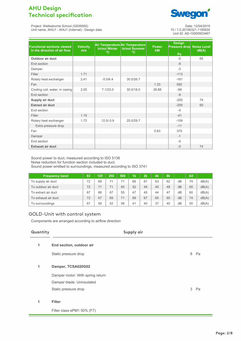
Appendix C – Manufacturer’s Plant Details

AHU Design Technical speci cation
Project: Wellesborne School (G939565)Unit name: AHU1 - AHU1 (Internal) - Design data
Date: 12/04/201915 / 1.0.20190321.1195930
Unit ID: AD-10000503467
GOLD F RXManufactured by Swegon, Kvänum, Sweden
Dimensioning data
Unit size 020
Air density 1.200 kg/m³
Supply air flow 1.400 m³/s
Static pressure drop Outdoor air duct 0 Pa
Supply air duct 200 Pa
Extract air flow 1.000 m³/s
Static pressure drop Extract air duct 200 Pa
Exhaust air duct 0 Pa
Climate data , GreatBritain
Design outdoor temperature, summer 30.0 °C
Design outdoor humidity, summer 50 %
Design outdoor temperature, winter -5.0 °C
Design outdoor humidity, winter 95 %
Supply air temperature, summer 18.0 °C
Supply air temperature, winter 23.0 °C
Key Performance Data
Specific fan power SFPv clean filters 1.25 kW/(m³/s)
Dry-bulb temperature efficiency of supply air 66.9 %
Eurovent Energy Efficiency Class A+ 2016
ErP Commission Regulation (EU) No 1253/2014 Compliant 2018
Casing
Construction Frameless, double skinned panels with mineral wool insulation
Panels 56mm thick with 1mm thick steel sheet inside and out. Outer sheet with grey painted finish
Thermal insulation class T2
Thermal bridging class TB2
Casing leakage class L1(M) / L2(R) according to EN 1886:2007 at -400 Pa and +400 Pa
Casing strength D1(M)
Electrical connections
GOLD F 3-phase, 5-wire, 400 V-10/+15%, 50 Hz, 10 A
Page: 1/8
AHU Design Technical speci cation
Project: Wellesborne School (G939565)Unit name: AHU1 - AHU1 (Internal) - Design data
Date: 12/04/201915 / 1.0.20190321.1195930
Unit ID: AD-10000503467
Functional sections viewedin the direction of air flow
Velocity m/s
Air Temperaturein/out Winter
°C
Air Temperaturein/out Summer
°CPower
kW
DesignPressure drop
Pa
Noise Level dB(A)
Outdoor air duct -0 65End section -8Damper -3Filter 1.71 -113Rotary heat exchanger 2.41 -5.0/6.4 30.0/26.7 -161Fan 1.33 592Cooling coil, water, in casing 2.05 7.1/23.0 30.0/18.0 28.88 -99End section -8Supply air duct -200 74Extract air duct -200 60End section -4Filter 1.15 -41Rotary heat exchanger 1.72 12.0/-3.9 25.0/29.7 -109 Extra pressure drop -11Fan 0.63 370Damper -1End section -5Exhaust air duct -0 74
Sound power to duct, measured according to ISO 5136Noise reduction for function section included to duct.Sound power emitted to surroundings, measured according to ISO 3741
Frequency band 63 125 250 500 1k 2k 4k 8k AllTo supply air duct 72 69 71 71 68 67 63 62 dB 74 dB(A)To outdoor air duct 72 71 71 60 52 49 45 48 dB 65 dB(A)To extract air duct 67 66 67 55 47 45 44 47 dB 60 dB(A)To exhaust air duct 72 67 69 71 68 67 65 65 dB 74 dB(A)To surroundings 67 59 52 56 41 40 37 40 dB 55 dB(A)
GOLD-Unit with control systemComponents are arranged according to airflow direction
Static pressure drop 8 Pa
End section, outdoor air1
Damper motor: With spring return
Damper blade: Uninsulated
Static pressure drop 3 Pa
Damper, TCSA020G021
Filter class ePM1 50% (F7)
Filter1
Supply airQuantity
Page: 2/8

AHU Design Technical speci cation
Project: Wellesborne School (G939565)Unit name: AHU1 - AHU1 (Internal) - Design data
Date: 12/04/201915 / 1.0.20190321.1195930
Unit ID: AD-10000503467
2x(592x592x520-10)
Velocity in the filter section 1.71 m/s
Recommended design pressure drop 113 Pa
Initial pressure drop 63 Pa
Final pressure drop 163 Pa
Rotary heat exchanger of type RECOnomic
Standard aluminium
Speed controlled
Pressure drop, supply air 161 Pa
Pressure drop, extract air 109 Pa
Extra pressure drop in extract air side (damper) to ensure the right flowdirection
11 Pa
Purging flow including leakage 0.078 m³/s
Dry-bulb temperature efficiency of supply air(83.2% at the same airflow) 66.9 %
Humidity efficiency, supply air, winter 0.0 %
Humidity efficiency, supply air, summer 0.0 %
Annual energy efficiency, dry conditions 34.1 %
Supply air side, winter In OutAir temperature -5.0 6.4 °CRelative humidity 95 42 %Heating power 19.32 kW
Extract air side, winter In OutAir temperature 12.0 -3.9 °CRelative humidity 20 61 %
Supply air side, summer In OutAir temperature 30.0 26.7 °CRelative humidity 50 61 %Cooling power 5.80 kW
Extract air side, summer In OutAir temperature 25.0 29.7 °CRelative humidity 50 38 %
Rotary heat exchanger, GOLD020FRXP011
Fan of type GOLD Wing+
Withdrawable fan with integrated airflow measurement
Direct drive with speed controlled EC motor
Fan1
Page: 3/8
AHU Design Technical speci cation
Project: Wellesborne School (G939565)Unit name: AHU1 - AHU1 (Internal) - Design data
Date: 12/04/201915 / 1.0.20190321.1195930
Unit ID: AD-10000503467
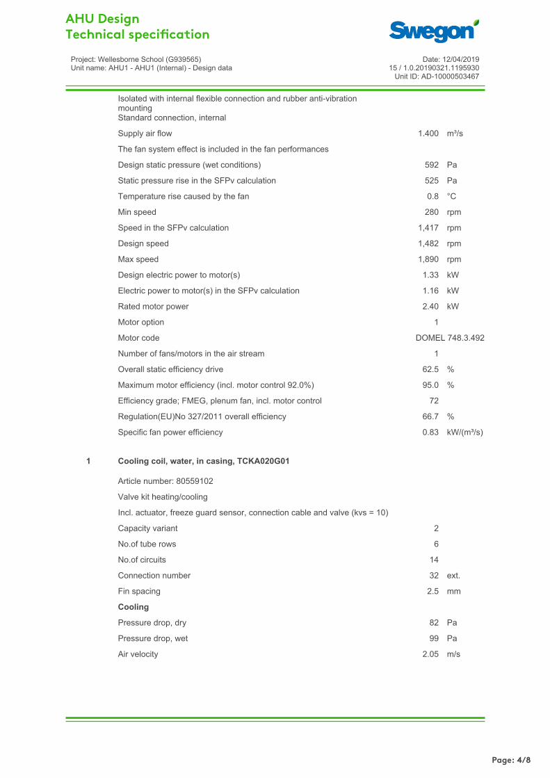
Isolated with internal flexible connection and rubber anti-vibrationmountingStandard connection, internal
Supply air flow 1.400 m³/s
The fan system effect is included in the fan performances
Design static pressure (wet conditions) 592 Pa
Static pressure rise in the SFPv calculation 525 Pa
Temperature rise caused by the fan 0.8 °C
Min speed 280 rpm
Speed in the SFPv calculation 1,417 rpm
Design speed 1,482 rpm
Max speed 1,890 rpm
Design electric power to motor(s) 1.33 kW
Electric power to motor(s) in the SFPv calculation 1.16 kW
Rated motor power 2.40 kW
Motor option 1
Motor code DOMEL 748.3.492
Number of fans/motors in the air stream 1
Overall static efficiency drive 62.5 %
Maximum motor efficiency (incl. motor control 92.0%) 95.0 %
Efficiency grade; FMEG, plenum fan, incl. motor control 72
Regulation(EU)No 327/2011 overall efficiency 66.7 %
Specific fan power efficiency 0.83 kW/(m³/s)
Article number: 80559102
Valve kit heating/cooling
Incl. actuator, freeze guard sensor, connection cable and valve (kvs = 10)
Capacity variant 2
No.of tube rows 6
No.of circuits 14
Connection number 32 ext.
Fin spacing 2.5 mm
Cooling
Pressure drop, dry 82 Pa
Pressure drop, wet 99 Pa
Air velocity 2.05 m/s
Cooling coil, water, in casing, TCKA020G011
Page: 4/8

AHU Design Technical speci cation
Project: Wellesborne School (G939565)Unit name: AHU1 - AHU1 (Internal) - Design data
Date: 12/04/201915 / 1.0.20190321.1195930
Unit ID: AD-10000503467
In OutAir temperature 30.0 18.0 °CRelative humidity 50 88 %
Sensible coil capacity 20.78 kW
Required total coil capacity 28.88 kW
Excess capacity of the coil 34 %
Amount of drained water 0.191 l/min
In OutLiquid temperature 6.0 12.0 °C
Flow of liquid 1.220 l/s
Liquid pressure drop 19.1 kPa
Liquid volume of the coil 16 l
Liquid type Ethylene-glycol
Ethylene-glycol 25 %/kg
Nom. pipe connection size, valve 25 ext.
Liquid pressure drop, open valve 19.4 kPa
Heating
Pressure drop 82 Pa
Air velocity 2.05 m/s
In OutAir temperature 7.1 23.0 °CRelative humidity 40 14 %
Required coil capacity 26.93 kW
Excess capacity of the coil 96 %
In OutLiquid temperature 45.0 40.0 °C
Flow of liquid 1.370 l/s
Liquid pressure drop 19.8 kPa
Liquid volume of the coil 16 l
Accessories
Quantity Product Article name1 Valve kit, heating and cooling TBVL-3-100-1
End section, supply air1
Page: 5/8

AHU Design Technical speci cation
Project: Wellesborne School (G939565)Unit name: AHU1 - AHU1 (Internal) - Design data
Date: 12/04/201915 / 1.0.20190321.1195930
Unit ID: AD-10000503467
Static pressure drop 8 Pa
Static pressure drop 4 Pa
End section, extract air1
Filter class ePM10 60% (M5)
2x(592x592x520-10)
Velocity in the filter section 1.15 m/s
Recommended design pressure drop 41 Pa
Initial pressure drop 21 Pa
Final pressure drop 62 Pa
Filter1
Accessories and technical data, see supply air
Rotary heat exchanger, GOLD020FRXP011
Fan of type GOLD Wing+
Withdrawable fan with integrated airflow measurement
Direct drive with speed controlled EC motor
Isolated with internal flexible connection and rubber anti-vibrationmountingStandard connection, internal
Extract air flow 1.000 m³/s
The fan system effect is included in the fan performances
Design static pressure (wet conditions) 370 Pa
Static pressure rise in the SFPv calculation 350 Pa
Temperature rise caused by the fan 0.5 °C
Min speed 280 rpm
Speed in the SFPv calculation 1,129 rpm
Design speed 1,155 rpm
Max speed 1,890 rpm
Design electric power to motor(s) 0.63 kW
Electric power to motor(s) in the SFPv calculation 0.59 kW
Rated motor power 2.40 kW
Motor option 1
Motor code DOMEL 748.3.492
Fan1
Extract airQuantity
Page: 6/8
AHU Design Technical speci cation
Project: Wellesborne School (G939565)Unit name: AHU1 - AHU1 (Internal) - Design data
Date: 12/04/201915 / 1.0.20190321.1195930
Unit ID: AD-10000503467
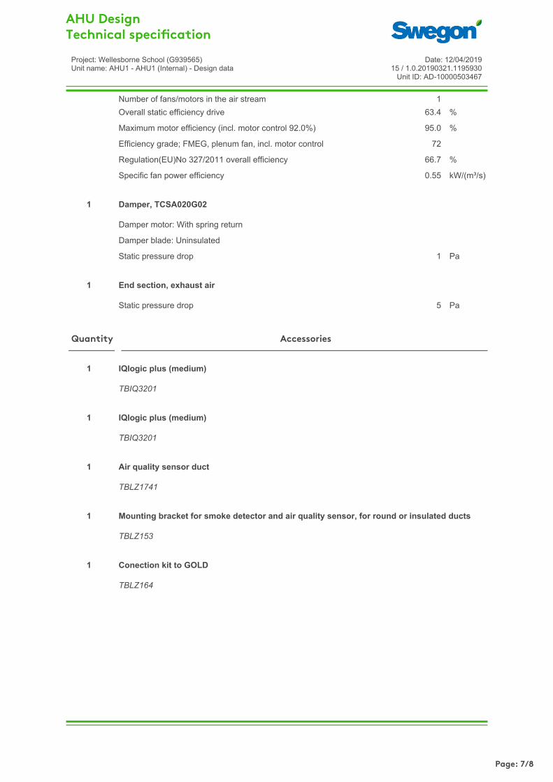
Number of fans/motors in the air stream 1Overall static efficiency drive 63.4 %
Maximum motor efficiency (incl. motor control 92.0%) 95.0 %
Efficiency grade; FMEG, plenum fan, incl. motor control 72
Regulation(EU)No 327/2011 overall efficiency 66.7 %
Specific fan power efficiency 0.55 kW/(m³/s)
Damper motor: With spring return
Damper blade: Uninsulated
Static pressure drop 1 Pa
Damper, TCSA020G021
Static pressure drop 5 Pa
End section, exhaust air1
TBIQ3201
IQlogic plus (medium)1
TBIQ3201
IQlogic plus (medium)1
TBLZ1741
Air quality sensor duct1
TBLZ153
Mounting bracket for smoke detector and air quality sensor, for round or insulated ducts1
TBLZ164
Conection kit to GOLD1
AccessoriesQuantity
Page: 7/8

Project: Wellesborne School (G939565)Unit name: AHU1 - AHU1 (Internal)Unit ID: AD-1000050346715 / 1.0.20190321.1195930Date: 12/04/2019
GOLD F RX
Unit size 020
Unit weight 892 kg
Duct Component Weight 0 kg
Length, max 2,998 mm
Height, max 1,727 mm
Width, max 1,400 mm
AHU Design Sketch: Inspection side
Connection size
outdoor air 1,000 x 400 mm
supply air 1,000 x 400 mm
extract air 1,000 x 400 mm
exhaust air 1,000 x 400 mm
Outdoor airSupply airExtract airExhaust air
Page: 8/8

Configured unit accessories
1PS - One user-side pump with tank
RA - Anti-freeze heaters
A41N - 415/3+N/50 power supply
RMMT - Maximum and minimum voltage relay
SMAR - Smartlink
AG - Rubber vibration dampers
General description
Air/water unit with hermetic scroll or rotary compressors, plate heat exchanger and axial fans. Refrigerant fluid: R410A.
SPECIFICATIONS
Structure
Made of galvanized sheet-iron coated with polyester powder at 180°C, which makes it highly resistant to weather conditions.The panels can be removed easily to allow full access to internal components.
7035
Compressors
Rotary vane compressors (sizes 6 and 8), complete with thermal overload protection included in the electric motor windings, and rubber vibration damping supports.Hermetic scroll compressors (sizes 10 to 14), complete with thermal overload protection included in the electric motor windings, crankcase heater and rubber vibration damping supports.
Coils
Consists of a row coil with copper tubes and aluminium fins having a large exchange surface. A grille with metal filter is installed as standard to protect the finned pack.
Fans
Epsilon Echos HP 31
Page 1 of 8BlueBoxGroup s.r.l., Via Valletta 5 - 30010 Cantarana di Cona (VE) –Italy
Tel: +39 0426 921111, Fax: +39 0426 302222
www.blueboxcooling.com
Prochill Bluebox
Print Date: 04/05/2019
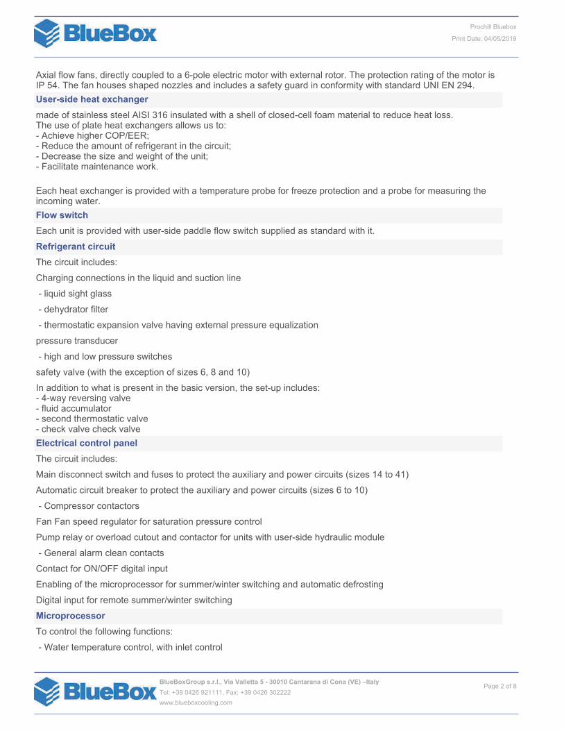
Axial flow fans, directly coupled to a 6-pole electric motor with external rotor. The protection rating of the motor is IP 54. The fan houses shaped nozzles and includes a safety guard in conformity with standard UNI EN 294.
User-side heat exchanger
made of stainless steel AISI 316 insulated with a shell of closed-cell foam material to reduce heat loss.The use of plate heat exchangers allows us to:- Achieve higher COP/EER;- Reduce the amount of refrigerant in the circuit;- Decrease the size and weight of the unit;- Facilitate maintenance work.
Each heat exchanger is provided with a temperature probe for freeze protection and a probe for measuring the incoming water.
Flow switch
Each unit is provided with user-side paddle flow switch supplied as standard with it.
Refrigerant circuit
The circuit includes:
Charging connections in the liquid and suction line
- liquid sight glass
- dehydrator filter
- thermostatic expansion valve having external pressure equalization
pressure transducer
- high and low pressure switches
safety valve (with the exception of sizes 6, 8 and 10)
In addition to what is present in the basic version, the set-up includes:- 4-way reversing valve- fluid accumulator- second thermostatic valve- check valve check valve
Electrical control panel
The circuit includes:
Main disconnect switch and fuses to protect the auxiliary and power circuits (sizes 14 to 41)
Automatic circuit breaker to protect the auxiliary and power circuits (sizes 6 to 10)
- Compressor contactors
Fan Fan speed regulator for saturation pressure control
Pump relay or overload cutout and contactor for units with user-side hydraulic module
- General alarm clean contacts
Contact for ON/OFF digital input
Enabling of the microprocessor for summer/winter switching and automatic defrosting
Digital input for remote summer/winter switching
Microprocessor
To control the following functions:
- Water temperature control, with inlet control
Page 2 of 8BlueBoxGroup s.r.l., Via Valletta 5 - 30010 Cantarana di Cona (VE) –Italy
Tel: +39 0426 921111, Fax: +39 0426 302222
www.blueboxcooling.com
Prochill Bluebox
Print Date: 04/05/2019

- Freeze protection
- Compressor timings
- High pressure alert management to prevent the unit from stopping in many cases
- Alarm signalling
- Alarm reset
- Self-adjusting control to enable optimal operation even when the water level in the system is low
- Display of the following on the display:
--> Outgoing water temperature
--> High pressure temperature
--> Temperature and differential set points
--> Description of alarms
--> Compressor operation hour meter
Standard power supply [V/ph/Hz]
230/1~/50 for sizes 6 and 8; 400/3N~/50 for sizes from 10 to 41
CONTROLS AND SAFETY DEVICES
All the units are fitted with the following control and safetycomponents:- high pressure switch with manual reset- high pressure safety device with automatic reset, for a limited number of occurrences, managed by the controller- low pressure safety device with automatic reset and limited tripping managed by the controller- high pressure safety valves- antifreeze probe at the outlet of the user-side heat exchangers- differential pressure switch already fitted on the user-side heat exchangers- overtemperature protection for compressors and fans overtemperature protection for compressors and fans
- High pressure switch with manual reset for each compressor;
- Low pressure switch with automatic reset and limited interventions managed by the control;
- High pressure safety valve (with the exception of sizes 6, 8 and 10);
- Protection against overtemperature for compressors;
- Condensation pressure control by means of Fan speed regulator for operation with low external temperatures;
TESTING
All the units are factory-tested and supplied complete with oil and refrigerant.
/1PS
with a circulator (sizes 6 to 18) or circulation pump (sizes 20 to 41), insulated storage tank
Other standard features
Summer/winter selection by digital input
Fitted as standard on all heat pumps. When the unit is switched on, it is always necessary to set an operating mode (heat pump or chiller). This remotely operable contact can be used to change the operating mode even from inside the building and without it being necessary to directly access the microprocessor control.
CONFIGURED UNIT ACCESSORIES DESCRIPTION
RA_anti - Anti-freeze heaters
Page 3 of 8BlueBoxGroup s.r.l., Via Valletta 5 - 30010 Cantarana di Cona (VE) –Italy
Tel: +39 0426 921111, Fax: +39 0426 302222
www.blueboxcooling.com
Prochill Bluebox
Print Date: 04/05/2019

This accessory consists of heaters inserted on the user-side heat exchanger to prevent damage to the hydraulic components due to the formation of ice during periods when the machine is stopped. The power of the anti-freeze heaters is only a few tens of watts depending on the model of unit, namely what is sufficient to prevent breakage of the components. The control monitors (even when the unit is on standby) the heat exchanger outlet probe and when this measures a water temperature below or equal to 5°C (or 2°C below the set point temperature, with differential of 1°C), it switches on the pump (if present) and starts the anti-freeze heater. If the temperature of the outgoing water reaches 4°C (or 3°C below the set point) the anti-freeze alarm will also be triggered; this stops the compressor while keeping the heaters active.
RMMT - Maximum and minimum voltage relay
This device carries out continuous control of the supply voltage of the unit and checks that it is always within an allowable range. If the voltage value stabilizes above or below this range, the device will stop the unit to prevent damage to the electric motors. This device will carry out phase sequence control.
SMAR - Smartlink
This accessory makes it possible to connect the controller of the unit with the controller of a Swegon GOLD™ airhandling unit via a simple serial cable, so allowing their operating logics to be merged into a single consciousness that pursues the maximum energy efficiency of thesystem. The RS485 serial interface is already included and dedicated to connection with Swegon units.
AG - Rubber anti-vibration mounts
These are supplied as a separate package from the unit and must be installed on site following the assembly diagram supplied. They allow you to reduce the vibrations transmitted from the unit to the surface it is standing on.
Page 4 of 8BlueBoxGroup s.r.l., Via Valletta 5 - 30010 Cantarana di Cona (VE) –Italy
Tel: +39 0426 921111, Fax: +39 0426 302222
www.blueboxcooling.com
Prochill Bluebox
Print Date: 04/05/2019
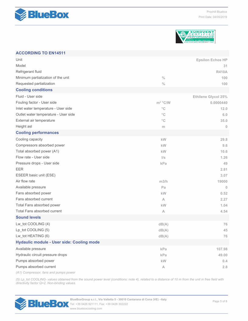
ACCORDING TO EN14511
Unit Epsilon Echos HP
Model 31
Refrigerant fluid R410A
Minimum partialization of the unit % 100
Requested partialization % 100
Cooling conditions
Fluid - User side Ethilene Glycol 25%
Fouling factor - User side m² °C/W 0.0000440
Inlet water temperature - User side °C 12.0
Outlet water temperature - User side °C 6.0
External air temperature °C 35.0
Height asl m 0
Cooling performances
Cooling capacity kW 29.8
Compressors absorbed power kW 9.6
Total absorbed power (A1) kW 10.6
Flow rate - User side l/s 1.26
Pressure drops - User side kPa 49
EER 2.81
ESEER basic unit (ESE) 3.07
Air flow rate m3/h 19000
Available pressure Pa 0
Fans absorbed power kW 0.52
Fans absorbed current A 2.27
Total Fans absorbed power kW 1.04
Total Fans absorbed current A 4.54
Sound levels
Lw_tot COOLING (4) dB(A) 76
Lp_tot COOLING (5) dB(A) 45
Lw_tot HEATING (6) dB(A) 76
Hydaulic module - User side: Cooling mode
Available pressure kPa 107.98
Hydraulic circuit pressure drops kPa 49.00
Pumps absorbed power kW 0.4
Pumps absorbed current A 2.8
(A1) Compressor, fans and pumps power
(5) Lp_tot COOLING- values obtained from the sound power level (conditions: note 4), related to a distance of 10 m from the unit in free field with directivity factor Q=2. Non-binding values.
Page 5 of 8BlueBoxGroup s.r.l., Via Valletta 5 - 30010 Cantarana di Cona (VE) –Italy
Tel: +39 0426 921111, Fax: +39 0426 302222
www.blueboxcooling.com
Prochill Bluebox
Print Date: 04/05/2019

(6) Lw_tot HEATING -unit operating at nominal operating capacity, without any accessories, with external air temperature of 7°C (6°C wb) and user-side heat exchanger water inlet-outlet temperature of 40-45°C. Values obtained from measures taken according to standard ISO 3744.
Reference conditions: External air temperature 35°C; user-side heat exchanger inlet-outlet water temperature 12-7°C.
(ESE) Former Eurovent’s seasonal efficiency index. Value not certified by Eurovent from 2019. Reference: base unit, without any accessories
Heating conditions
Inlet water temperature - User side °C 40.0
Outlet water temperature - User side °C 45.0
External air temperature °C -5.0
External Relative Humidity % 95
Heating performances
Heating capacity kW 27.1
Compressors absorbed power kW 9.3
Total absorbed power (A1) kW 10.4
Flow rate - User side l/s 1.40
Pressure drops - User side kPa 58
COP 2.60
SCOP MT (B2) (-)
ƞ sh MT (B2) % 0
SCOP LT (B2) 3,21(●)
ƞ sh LT (B2) % 125.5
Air flow rate m3/h 19000
Available pressure Pa 0
Fans absorbed power kW 0.52
Fans absorbed current A 2.27
Total Fans absorbed power kW 1.04
Total Fans absorbed current A 4.54
Hydaulic module - User side: Heating mode
Available pressure kPa 85.50
Hydraulic circuit pressure drops kPa 58.23
Pumps absorbed power kW 0.4
Pumps absorbed current A 2.8
(A1) Compressor, fans and pumps power
(B2) with reference to regulation 2013/813 and norm EN 14825. The SCOP LT value is certified by Eurovent for units with Pdesign <70 kW
(ErP legenda) – Not ErP compliant • ErP compliant o ErP compliant only with option VEC (EC fans)
Compressors
Type Scroll
Number 1
Refrigerant circuits 1
Total oil charge kg 2.8
Total refrigerant charge (estimated) (NRef) kg 13.0
Fans
Type Axial-STD
Page 6 of 8BlueBoxGroup s.r.l., Via Valletta 5 - 30010 Cantarana di Cona (VE) –Italy
Tel: +39 0426 921111, Fax: +39 0426 302222
www.blueboxcooling.com
Prochill Bluebox
Print Date: 04/05/2019
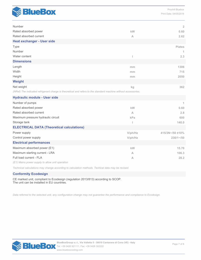
Number 2
Rated absorbed power kW 0.60
Rated absorbed current A 2.62
Heat exchanger - User side
Type Plates
Number 1
Water content l 2.3
Dimensions
Length mm 1306
Width mm 715
Height mm 2050
Weight
Net weight kg 362
(NRef) The indicated refrigerant charge is theoretical and refers to the standard machine without accessories.
Hydraulic module - User side
Number of pumps 1
Rated absorbed power kW 0.60
Rated absorbed current A 2.8
Maximum pressure hydraulic circuit kPa 600
Storage tank l 140.0
ELECTRICAL DATA (Theoretical calculations)
Power supply V/ph/Hz 415/3N~/50 ±10%
Control power supply V/ph/Hz 230/1~/50
Electrical performances
Maximum absorbed power (E1) kW 15.70
Maximum starting current - LRA A 106.3
Full load current - FLA A 28.2
(E1) Mains power supply to allow unit operation
Technical calculations may change according to calculation methods. Techical data may be revised.
Conformity Ecodesign
CE marked unit, compliant to Ecodesign (regulation 2013/813) according to SCOP. The unit can be installed in EU countries.
Data referred to the selected unit, any configuration change may not guarantee the performance and compliance to Ecodesign.
Page 7 of 8BlueBoxGroup s.r.l., Via Valletta 5 - 30010 Cantarana di Cona (VE) –Italy
Tel: +39 0426 921111, Fax: +39 0426 302222
www.blueboxcooling.com
Prochill Bluebox
Print Date: 04/05/2019
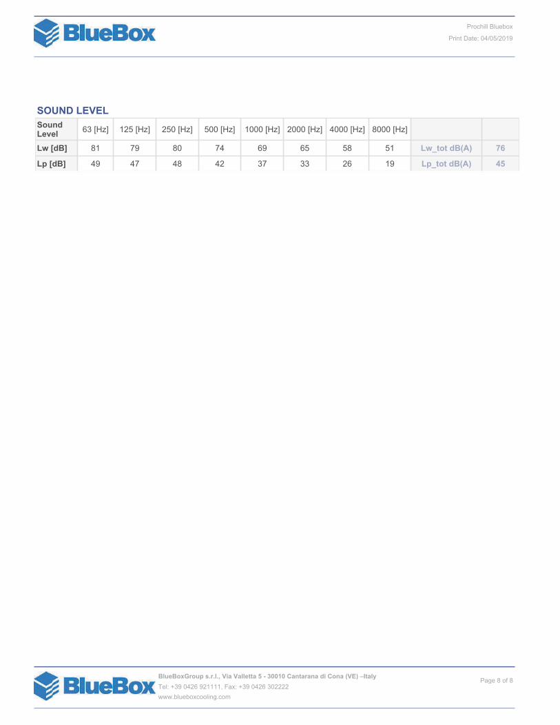
SOUND LEVEL
SoundLevel
63 [Hz] 125 [Hz] 250 [Hz] 500 [Hz] 1000 [Hz] 2000 [Hz] 4000 [Hz] 8000 [Hz]
Lw [dB] 81 79 80 74 69 65 58 51 Lw_tot dB(A) 76
Lp [dB] 49 47 48 42 37 33 26 19 Lp_tot dB(A) 45
Page 8 of 8BlueBoxGroup s.r.l., Via Valletta 5 - 30010 Cantarana di Cona (VE) –Italy
Tel: +39 0426 921111, Fax: +39 0426 302222
www.blueboxcooling.com
Prochill Bluebox
Print Date: 04/05/2019

Sample Construction Code Format Diagram
Construction Code Definitions
Code Section Code Description
Model S Rectangular attenuator with SPLITTER elements
Base material G Standard gauge galvanised sheet steel
No. delivery sections 01 upwards This number confirms how many sections will be delivered to site for each attenuator or splitter. For02 or above assembly will be required by others
Element type H Elements installed in the horizontal plane
V Elements installed in the vertical plane
Pressure rating 3 High pressure (+2000/-750Pa)
End connections C 30mm profile flanges (profile flanges are compatible with Doby, Mez & Metu flanges)
Packing L Lightweight pallet wrapping on casing ends (EG/IG units are palletised and wrapped on the pallet)
Optional features M Infill protected by Melinex polyester film
S Side elements (for EG/IG units these are supplied with steel backing)
Attenuator Construction Code Definitions
Project: Wellesbourne School Date: 09/04/2019
Page 5 of 7
Document Package 94390/2/1/1
Direct Telephone 01756 708768
Direct E-Mail [email protected]

09/04/2019
Construction Codes confirm the physical properties of each item. This drawing must therefore be read in conjunction with the Construction Code Definitions.
Project: Wellesbourne School Date:
Dimensions W1, H1, W2, H2, WD1, HD1 are always shown as "inside-duct". Dimensions L1, L2, LD1 are always shown as "over connections".
SG splitter attenuator - with profile flanges
W1
Primary Dimensions
Ref. Construction Code H1 L1 Paint Colour Wt (Kg)No.OffNDLLD1
Delivery Data
FlangeSize
1000ATT/01 SG01H/3C/L/S 400 900 48 1900 1 30mm
900ATT/02 SG01H/3C/L/S 400 2400 110 12400 1 30mm
750ATT/03 SG01V/3C/L/S 400 2100 94 12100 1 30mm
750ATT/04 SG01V/3C/L/S 400 1800 83 11800 1 30mm
750ATT/05 SG01V/3C/L/SM 400 1800 86 11800 1 30mm
750ATT/06 SG01V/3C/L/SM 400 1800 86 11800 1 30mm
Attenuator Drawings
Page 6 of 7
Document Package 94390/2/1/1
Direct Telephone 01756 708768
Direct E-Mail [email protected]

Noise Data TypeNoise Data Source 8k4k2k1k50025012563Total Static
Pressure (Pa)Vol
(m³/s)Description
Octave band mid frequency (Hz)
Ref.
01.40AHU FRESH AIR INTAKE 69 67 62 59 56 57 61 59Manufacturer In-duct LwATT/01
01.40AHU SUPPLY AIR OUT 74 70 77 74 73 66 63 58Manufacturer In-duct LwATT/02
01.40AHU EXTRACT AIR IN 71 68 67 57 58 58 66 64Manufacturer In-duct LwATT/03
01.40AHU EXHAUST AIR OUT 77 74 83 78 78 72 68 63Manufacturer In-duct LwATT/04
00.00
Equipment Noise Data Schedule
Project: Wellesbourne School Date: 09/04/2019
Page 7 of 7
Document Package 94390/2/1/1
Direct Telephone 01756 708768
Direct E-Mail [email protected]

Noise Assessment
Warwickshire County Council A112162
Wellesbourne Primary School April 2019
Appendix D – Report Conditions
This Report has been prepared using reasonable skill and care for the sole benefit of Warwickshire County
Council (“the Client”) for the proposed uses stated in the report by WYG Environment Planning Transport
Limited (“WYG”). WYG exclude all liability for any other uses and to any other party. The report must not be
relied on or reproduced in whole or in part by any other party without the copyright holder’s permission.
No liability is accepted or warranty given for; unconfirmed data, third party documents and information
supplied to WYG or for the performance, reliability, standing etc of any products, services, organisations or
companies referred to in this report. WYG does not purport to provide specialist legal, tax or accounting
advice.
The report refers, within the limitations stated, to the environment of the site in the context of the
surrounding area at the time of the inspections'. Environmental conditions can vary and no warranty is given
as to the possibility of changes in the environment of the site and surrounding area at differing times. No
investigative method can eliminate the possibility of obtaining partially imprecise, incomplete or not fully
representative information. Any monitoring or survey work undertaken as part of the commission will have
been subject to limitations, including for example timescale, seasonal and weather-related conditions. Actual
environmental conditions are typically more complex and variable than the investigative, predictive and
modelling approaches indicate in practice, and the output of such approaches cannot be relied upon as a
comprehensive or accurate indicator of future conditions. The “shelf life” of the Report will be determined by
a number of factors including; its original purpose, the Client’s instructions, passage of time, advances in
technology and techniques, changes in legislation etc. and therefore may require future re-assessment.
The whole of the report must be read as other sections of the report may contain information which puts
into context the findings in any executive summary.
The performance of environmental protection measures and of buildings and other structures in relation to
acoustics, vibration, noise mitigation and other environmental issues is influenced to a large extent by the
degree to which the relevant environmental considerations are incorporated into the final design and
specifications and the quality of workmanship and compliance with the specifications on site during
construction. WYG accept no liability for issues with performance arising from such factors.

Noise Assessment
Warwickshire County Council A112162
Wellesbourne Primary School April 2019
Appendix E – Comments Response to EHO – 20th
February 2019

A112162 February 2019
A112162 20th February 2019
Response to comments from Ben Ellis, Environmental Health Officer Stratford-on-Avon
District Council, received on 14th February 2019.
WYG Responses in Blue
SoADC Comment 1
There is not enough information to accurately assess the impacts from this development at this time.
Further information is required in particular - Assumptions made in the propagation model including:
1. Assumptions used for ground hardness and other factors in ISO 9613
2. As submitted plan is not to scale- distances used from sources to receptors
3. Attenuated louvres from AHU- what is the internal plant room noise including reflection. What is the
resulting external noise level taking into account size and construction of louvres
4. The propagation model shows some attenuation provided by fences at the rear gardens of noise sensitive
receptors- what is the construction of this fence and how has it been accounted for in the model
5. What, if any, attenuation has been presumed from the hit and miss fencing surrounding the HVAC units
6. Will there be any noise breakout from the ducting in the roof space
WYG Response 1
1. Hard ground has been used at all locations within the models with ground absorption set to 0,
representing a worst-case scenario.
2. Table 1.0 below documents the distances from the proposed plant to the closest receptors.
Table 1.0 Sensitive Receptor Locations and Distance to Source
Ref. Description Closest Source Approximate Distance To Source (m)
R01 60 Mountford Close AHU 90
R02 62 Mountford Close AHU 70
R03 64 Mountford Close AHU 52
R04 66 Mountford Close AHU 42
R05 68 Mountford Close AHU 29
R06 70 Mountford Close AHU 24
R07 72 Mountford Close AHU 33
R08 74 Mountford Close AHU 50
R09 76 Mountford Close AHU 66
R10 78 Mountford Close HVAC 98
R11 80 Mountford Close HVAC 112
3. The sound power level of sound break out from the Geniox 14DR AHU is 56 dB(A). The breakout from
the AHU plant room has been included in the model as a vertical area source at 4.1m across and 3.0m high

A112162 February 2019
on the southeast façade of the proposed extension. The vertical area source does not include the effects
of additional louvres associated with the AHU, which would be likely to provide additional noise attenuation,
so transmission loss is assumed to be 0. Therefore, the modelling of the breakout associated with the AHU
is considered to represent a worst-case scenario. All manufacturers’ data associated with the plant is
appended to this document.
4. From on-site observations, the garden fences at the closest receptors are constructed of solid timber,
which have been included in the models as a solid barrier at 1.8m high, which is the standard height for
most garden fences.
5. No attenuation has been included with respect to the hit and miss fencing surrounding the HVAC units,
therefore representing a worst-case scenario.
6. It is understood there will be no noise breakout from ducting in the roof space (which will be located
internally within the building) as the building itself would contain the casing breakout. Furthermore, casing
noise breakout would typically be at least 10 dB lower than from the external termination point and would
have an overall negligible contribution to noise levels when compared to the proposed AHU and HVAC units
to be installed.
SoADC Comment 2
Sound measurements:
7. Justification for measurement locations
8. How does the LAeq and LA90 level change throughout the day- please provide results broken into 1hr periods
(daytime) and 15 Mins (Night time) for the long term measurements. What is the min, max and modal and
average 1hr average (daytime) and 15 mins (night time)
9. What was the weather like during this long term monitoring
10. How do the measurements taken at the LT monitoring sites compare with the attended measurements
WYG Response 2
7. The noise monitoring locations were selected due to their proximity to the closest sensitive receptors
and distances from existing noise sources including the existing school and surrounding road network. The
monitoring locations are therefore considered to suitably represent background level (LA90) in accordance
with the requirements of BS 4142:2014.
8. Tables A1 and A2 within the appendix of this document detail the hourly breakdown of both the long-
term measurements (LT1 and LT2) for the LAeq and LA90 (rounded), including the minimum, maximum and
modal values for daytime and night-time hours during both weekdays and weekends.

A112162 February 2019
Within the BS 4142 assessment, a background level of 36 dB (weekend daytime LA90) for daytime hours
and 28 dB (weekend night-time LA90) for night-time hours were considered to represent typical background
levels when the school was not in use, as shown in the summary table provided in Table 4.3 of the Noise
Technical Report, with data from LT1 used, as it is located next to the closest sensitive receptors. It is
understood that the plant will only operate during weekday hours, however, overall background levels
measured during weekend hours were lower than those measured during the weekday period, and so were
used to represent a worst-case. It is also understood that the plant is unlikely to be operational during
night-time hours, however this was assessed to demonstrate that if the plant were to be operational during
the night-time, noise levels would still fall below existing background noise levels at all sensitive receptors.
Although monitoring location LT2 lies closer to sensitive receptors R08-R11, if baseline data from this
location were to be used (daytime LA90 levels of 40 dB and night-time LA90 levels of 18 dB) noise rating
levels from the plant would still fall at or below background levels during the daytime and night-time
periods.
9. Weather data from Wellesbourne Airfield was reviewed, which identifies that conditions during the long-
term monitoring were observed as being mainly dry, with average temperatures between 2o and 4O Celsius
with wind speeds of up to 7kts (3.6 m/s). Further meteorological conditions observed during the short-
term monitoring period are detailed in Table 4.2 of the Noise Technical Report.
10. Short-term measurements were undertaken during the daytime period (07:00-23:00). The results are
summarised in Table 4.3 of the Noise Technical Report. The LAeq and LA90 levels from at the long-term
monitoring locations and the short-term monitoring locations match closely as shown below in Table 2.0.
Table 2.0 Comparison of Long-term and Short-term Monitoring
Monitoring LAeq (dB) LA90 (dB)
Long-term 49.9-61.7 36.0-42.0
Short-term 44.9-64.9 36.5-44.8
SoADC Comment 3
Background sound levels:
11. How were the representative background sound levels at the noise sensitive properties derived for the
BS4142 assessment how does this compare to the worst case 1hr (daytime) or 15 min (night-time) period
WYG Response 3
11. Considered in Response 2 (8).

A112162 February 2019
SoADC Comment 4
Sound sources:
12. More information is required into the hours of operation of the various pieces of equipment including their
hours of operation
13. The assessment has assumed a 2dB penalty for tonality Is a penalty for intermittency also appropriate
given hours and times of operation
14. If it is the authors experience that tonal noise is not attributable to this type of equipment but that it is
likely to be otherwise distinguishable against the residual acoustic environment a penalty of 3db should be
applied
15. Do the HVAC have defrost mode and what sound level is this. Is this an automatic function that can occur
at night
16. The extract louvre from the kitchen extraction doesn’t seem to be assessed- this is apparently located at a
high level to the North East of the proposal. What is the impact of this noise on the assessment
WYG Response 4
12, 15 & 16. The assessment has been undertaken assuming all items of plant are working at full capacity,
simultaneously during daytime and night-time hours, to present a robust assessment, even though it is not
anticipated to occur. Clarification from the mechanical engineer regarding points 12, 15 and 16 have been
sought, with the response detailed below:
“General hours of operation for the AHU and AC plant will be as per the normal school hours, allowing for
teaching staff arriving prior to the start of the school day and cleaning staff afterwards – typically 8:00am
to 6:00pm. We would not anticipate HVAC plant to be running for any more than 1 hour each side of these
times to allow for heat-up / cool down.
With regard to frost protection, we have not specified this function, but in any case if such function were
included, running noise levels would be no higher than normal operation.
With regard to defrost mode, this is an automatic function of the specified air-source heat pumps /
condensers. Whilst this function can activate automatically, it would only do so when the units are already
running, within the time range referred to above. Again, running noise levels will be no higher as the units
just goes into reverse mode / cycle.
Finally, regarding the kitchen equipment & extract, this would generally be limited to late morning to
lunchtime.”
As detailed above, the worst-case proposed hours of operation would be between 07:00-19:00 during
weekday periods. During these hours, noise levels are predicted to be up to 10dB below background levels
and would therefore have no impact on the closest sensitive receptors
The kitchen extract louvre is located on the northern façade of the proposed extension, which faces away
from the closest sensitive receptors. Also, as detailed above, the extract louvre would only be used during

A112162 February 2019
late morning to lunchtime hours. As the noise levels from the AHU and HVAC fall at least 10 dB below
background levels during the daytime, it is unlikely that noise from the kitchen extract louvre will have an
adverse impact on sensitive receptors.
13 & 14. The proposed plant is not expected to have any tonal features that would be readily distinguishable
against the existing background, however as a worst-case assumption, a 2 dB penalty for any potential
tonal elements that may be just perceptible was applied. No further corrections were added as predicted
noise levels during the daytime are 10 dB below the background noise level which would be imperceptible
and indistinguishable when, for instance switching on.
SoADC Comment 5
What is the impact of uncertainty in the assessment including uncertainty in propagation, source sound
levels, and deriving background measurements.
WYG Response 5
Guidance presented in BS 4142:2014 details steps necessary to reduce uncertainty within assessments.
The points below detail the steps taken to reduce uncertainty within the assessment:
• Noise source data from the AHU and HVAC units has been taken from published manufacturer’s data
(appended to this document). The sound power levels have been used within the model, with no
attenuation provided from the louvre associated with the AHU and hit and miss fencing around the HVAC
units, therefore representing a worst-case scenario.
• The locations selected for the noise monitoring survey were chosen as they represent the closest sensitive
receptors in terms of proximity to the proposed plant reducing the uncertainty level of the residual noise
environment prior to installation of the plant.
• The long-term monitoring was also carried out over weekday and weekend periods, even though the likely
operational hours of the plant is weekday only.
• Hard ground has been used in the models as this provides no attenuation between the proposed plant and
closest receptors therefore the noise propagation characteristics are considered to be representative of a
worst-case scenario.
• As detailed in response 2 (8), worst-case background levels were chosen from the LT1 weekend period to
determine background noise levels in the absence of contributions from the existing school, even though
the plant is likely to only be operational during the weekday period. A night-time assessment was also
undertaken even though the plant is only to be operational during the daytime. The assessment therefore
represents a worst-case scenario.
• All monitoring equipment was appropriately calibrated as detailed in Section 4.0 of the Noise Technical
Report.
Emma Aspinall Sam Moran Environmental Consultant Associate

A112162 February 2019
Appendices
Hourly Breakdown of Long-term Data
Table A1 LT1 Hourly Breakdown
Time Weekday Saturday Sunday
LAeq LA90 LAeq LA90 LAeq LA90
Night-time
23:00 44.4 36.0 29.7 21.0 36.7 31.0
00:00 42.5 34.0 39.4 29.0 26.1 18.0
01:00 35.2 30.0 36.0 26.0 24.7 16.0
02:00 34.2 30.0 36.3 27.0 27.4 17.0
03:00 36.2 32.0 39.8 29.0 25.7 18.0
04:00 36.7 33.0 45.3 36.0 36.3 22.0
05:00 41.6 35.0 44.5 35.0 32.0 23.0
06:00 53.7 39.0 48.0 39.0 45.2 29.0
Min 34.2 30.0 29.7 21.0 24.7 16.0
Max 53.7 39.0 48.0 39.0 45.2 31.0
Mode - 30.0 36.0 29.0 26.0 18.0
Daytime
07:00 56.9 43.0 55.4 39.0 57.0 32.0
08:00 61.0 44.0 50.1 39.0 55.7 32.0
09:00 57.0 42.0 47.8 38.0 54.8 33.0
10:00 63.0 46.0 48.3 37.0 53.1 34.0
11:00 59.4 41.0 48.2 38.0 57.2 32.0
12:00 70.3 51.0 46.1 36.0 53.4 33.0
13:00 57.9 41.0 46.5 35.0 48.3 34.0
14:00 68.2 46.0 47.4 32.0 48.9 34.0
15:00 56.9 44.0 46.0 32.0 52.9 33.0
16:00 52.8 40.0 47.2 34.0 54.6 34.0
17:00 49.4 41.0 44.1 33.0 44.8 35.0
18:00 44.8 40.0 38.1 32.0 40.8 36.0
19:00 46.5 39.0 34.8 29.0 40.9 36.0
20:00 42.9 36.0 31.8 25.0 41.0 36.0
21:00 42.8 36.0 32.1 23.0 40.4 35.0
22:00 44.0 38.0 32.5 22.0 38.9 33.0
Min 42.8 36.0 31.8 22.0 38.9 32.0
Max 70.3 51.0 55.4 39.0 57.2 36.0
Mode 57.0 41.0 48.0 32.0 53.0 33.0
Table A2 LT2 Hourly Breakdown
Time Weekday Saturday Sunday
LAeq LA90 LAeq LA90 LAeq LA90
Night-time
23:00 45.3 36.0 34.4 20.0 39.2 31.0
00:00 44.2 34.0 34.5 26.0 31.8 17.0
01:00 37.9 31.0 30.3 23.0 28.7 16.0
02:00 37.0 30.0 31.7 23.0 28.0 16.0
03:00 38.0 32.0 35.7 26.0 30.4 17.0

A112162 February 2019
Time Weekday Saturday Sunday
LAeq LA90 LAeq LA90 LAeq LA90
04:00 39.0 33.0 40.5 32.0 36.9 19.0
05:00 42.6 37.0 40.9 32.0 32.5 21.0
06:00 50.0 41.0 44.5 36.0 42.9 27.0
Min 37.0 30.0 30.3 20.0 28.0 16.0
Max 50.0 41.0 44.5 36.0 42.9 31.0
Mode 38.0 - 41.0 26.0 - 17.0
Daytime
07:00 51.3 45.0 45.7 36.0 47.5 33.0
08:00 52.9 46.0 45.6 37.0 46.9 33.0
09:00 53.3 43.0 45.1 37.0 52.8 33.0
10:00 56.1 43.0 47.6 36.0 58.0 34.0
11:00 57.2 43.0 45.0 37.0 46.9 34.0
12:00 57.6 46.0 44.8 36.0 56.0 36.0
13:00 53.1 42.0 45.7 35.0 52.3 36.0
14:00 53.5 43.0 44.3 33.0 46.0 36.0
15:00 54.3 43.0 46.3 34.0 53.3 37.0
16:00 46.8 40.0 45.7 33.0 58.9 38.0
17:00 48.0 41.0 40.2 32.0 44.1 38.0
18:00 45.9 40.0 38.8 30.0 43.6 38.0
19:00 46.9 39.0 35.3 27.0 44.2 37.0
20:00 43.8 36.0 37.6 23.0 44.1 37.0
21:00 43.0 35.0 35.6 21.0 43.4 36.0
22:00 44.5 38.0 35.7 21.0 42.0 34.0
Min 43.0 35.0 35.3 21.0 42.0 33.0
Max 57.6 46.0 47.6 37.0 58.9 38.0
Mode 53.0 43.0 46.0 36.0 44.0 36.0

A112162 February 2019
Manufacturers’ Plant Data

PKA-M R410A
Power Inverter Heat Pump
Wall Mounted SystemAir Conditioning
Key Features
Improved airflow control, including adjustable louvres for uniform air distribution
Internal pipe connection to wall mounted unit for easy and neat installation
CN22 connector as standard for connection to PAR-33MAA hard wired controller
Replace Technology available
The PKA-M Power Inverter range is a wall mounted system that blends a host ofoutstanding features with a sophisticated flat panel, streamlined design. Offering highseasonal efficiency, advanced control options and quiet operation, this range providesextreme flexibility and ease of installation.
Product Information

PKA-M R410A
Power Inverter Heat Pump
Wall Mounted SystemAir Conditioning
Product Information
PRODUCT DIMENSIONS
Upper View
CAPACITY (kW) Heating (nominal)
Cooling (nominal)
Heating (UK)
Cooling (UK)
SHF (nominal)
COP / EER (nominal)
SCOP / SEER (BS EN14825)
ErP ENERGY EFFICIENCY CLASS Heating/Cooling
AIRFLOW (l/s) Lo-Mi-Hi
PIPE SIZE mm (in) Gas
Liquid
SOUND PRESSURE LEvEL (dBA)
SOUND POWER LEvEL (dBA)
DIMENSIONS (mm) Width x Depth x Height
WEIGHT (kg)
ELECTRICAL SUPPLY
FUSE RATING (BS88) - HRC (A)
INTERCONNECTING CABLE No. Cores
WIRED REMOTE CONTROLLER REFERENCE
WIRELESS REMOTE CONTROLLER REFERENCE
PKA-M - INDOOR UNITS
4.1 (1.6-5.2)
3.6 (1.6-4.5)
3.5 (1.35-4.4)
3.3 (1.45-4.15)
0.81
3.83 / 3.83
3.9 / 5.9
A / A+
150-175-200
12.7 (1/2”)
6.35 (1/4”)
36-40-43
60
898 x 249 x 295
13
Fed by Outdoor Unit
6
4
PAR-33MAA
PAR-FL32MA
5.0 (2.5-7.3)
4.6 (2.3-5.6)
4.25 (2.15-6.2)
4.23 (2.1-5.15)
0.72
3.33 / 3.26
4.0 / 5.4
A+ / A
150-175-200
12.7 (1/2”)
6.35 (1/4”)
36-40-43
60
898 x 249 x 295
13
Fed by Outdoor Unit
6
4
PAR-33MAA
PAR-FL32MA
7.0 (2.8-8.2)
6.1 (2.7-6.7)
5.95 (2.4-6.95)
5.5 (2.5-6.15)
0.86
3.57 / 3.81
4.2 / 6.5
A+ / A++
300-333-367
15.88 (5/8”)
9.52 (3/8”)
39-42-45
64
1170 x 295 x 365
21
Fed by Outdoor Unit
6
4
PAR-33MAA
PAR-FL32MA
8.0 (3.5-10.2)
7.1 (3.3-8.1)
6.8 (3.0-8.65)
6.55 (3.05-7.45)
0.78
3.65 / 3.94
4.3 / 6.7
A+ / A++
300-333-367
15.88 (5/8”)
9.52 (3/8”)
39-42-45
64
1170 x 295 x 365
21
Fed by Outdoor Unit
6
4
PAR-33MAA
PAR-FL32MA
11.2 (4.5-14.0)
9.5 (4.9-11.4)
9.5 (3.85-11.9)
9.2 (4.5-10.5)
0.73
3.68 / 3.96
4.1 / 6.3
A+ / A++
333-383-433
15.88 (5/8”)
9.52 (3/8”)
41-45-49
65
1170 x 295 x 365
21
Fed by Outdoor Unit
6
4
PAR-33MAA
PAR-FL32MA
PKA-M35HA PKA-M50HA PKA-M60KA PKA-M71KA PKA-M100KA
PUHZ-ZRP - OUTDOOR UNITS
SOUND PRESSURE LEvEL (dBA) Heating/Cooling
SOUND POWER LEvEL (dBA) Cooling
WEIGHT (kg)
DIMENSIONS (mm) Width x Depth x Height
ELECTRICAL SUPPLY
PHASE
Heating/Cooling (nominal)
Heating/Cooling (UK)
STARTING CURRENT (A)
SYSTEM RUNNING CURRENT (A) Heating/Cooling [MAX]
FUSE RATING (BS88) - HRC (A)
MAINS CABLE No. Cores
MAX PIPE LENGTH (m)
MAX HEIGHT DIFFERENCE (m)
CHARGE REFRIGERANT (kg) / CO2 EQUIvALENT (t)
R410A (GWP 2088) - 30m
MAX ADDITIONAL REFRIGERANT (kg) / CO2 EQUIvALENT (t)
R410A (GWP 2088)
46 / 44
65
43
809 x 300 x 630
220-240v, 50Hz
Single
1.07 / 0.94
0.89 / 0.80
4.0
4.22 / 3.94 [13.4]
16
3
50
30
2.20 / 4.59
0.40 / 0.84
46 / 44
65
46
809 x 300 x 630
220-240v, 50Hz
Single
1.50 / 1.41
1.26 / 1.20
5.0
7.16 / 6.59 [13.4]
16
3
50
30
2.40 / 5.01
0.40 / 0.84
48 / 47
67
70
950 x 330 + 30 x 943
220-240v, 50Hz
Single
1.96 / 1.60
1.64 / 1.36
5.0
9.23 / 8.11 [19.4]
25
3
50
30
3.50 / 7.31
1.20 / 2.51
48 / 47
67
70
950 x 330 + 30 x 943
220-240v, 50Hz
Single
2.19 / 1.80
1.84 / 1.53
6.0
8.75 / 7.79 [19.4]
25
3
50
30
3.50 / 7.31
1.20 / 2.51
51 / 49
69
116
1050 x 330 + 40 x 1338
220-240v, 50Hz
Single
3.04 / 2.40
2.55 / 2.04
12.0
11.35 / 11.26 [27.1]
32
3
75
30
5.00 / 10.44
2.40 / 5.01
PUHZ-ZRP35VKA2 PUHZ-ZRP50VKA2 PUHZ-ZRP60VHA2 PUHZ-ZRP71VHA2 PUHZ-ZRP100VKA3
11.2 (4.5-14.0)
9.5 (4.9-11.4)
9.5 (3.85-11.9)
9.2 (4.5-10.5)
0.73
3.68 / 3.96
4.1 / 6.2
A+ / A++
333-383-433
15.88 (5/8”)
9.52 (3/8”)
41-45-49
65
1170 x 295 x 365
21
Fed by Outdoor Unit
6
4
PAR-33MAA
PAR-FL32MA
PKA-M100KA
51 / 49
69
123
1050 x 330 + 40 x 1338
380-415v, 50Hz
Three
3.04 / 2.40
2.55 / 2.04
4.0
4.06 / 4.03 [8.6]
16
5
75
30
5.00 / 10.44
2.40 / 5.01
PUHZ-ZRP100YKA3
SYSTEM POWERINPUT (kW)
Three Phase3
3
197
387 192
599
249 5
155688
898
55
295
65.2
423.7 431.7
1114
0.3
5295
1
1170
365
74 (855) 241
PKA-M35/50HA PRODUCT DIMENSIONS PKA-M60/71/100KA
UNITED KINGDOM Mitsubishi Electric Europe Living Environment Systems Division
Travellers Lane, Hatfield, Hertfordshire, AL10 8XB, England General Enquiries Telephone: 01707 282880 Fax: 01707 278881
IRELAND Mitsubishi Electric Europe Westgate Business Park, Ballymount, Dublin 24, Ireland
Telephone: Dublin (01) 419 8800 Fax: Dublin (01) 419 8890 International code: (003531)
Telephone: 01707 282880email: [email protected]
web: airconditioning.mitsubishielectric.co.uk
Note: The fuse rating is for guidance only. Please refer to the relevant databook for detailed specification. It is the responsibility of a qualified electrician/electrical engineer to select the correct cable size and fuse rating based on current regulationand site specific conditions. Mitsubishi Electric’s air conditioning equipment and heat pump systems contain a fluorinated greenhouse gas, R410A (GWP:2088), R32 (GWP:675), R407C (GWP:1774) or R134a (GWP:1430). *These GWPvalues are based on Regulation (EU) No 517/2014 from IPCC 4th edition. In case of Regulation (EU) No.626/2011 from IPCC 3rd edition, these are as follows. R410A (GWP:1975), R32 (GWP: 550), R407C (GWP:1650) or R134a (GWP:1300).
Country of origin: United Kingdom – Japan – Thailand – Malaysia. ©Mitsubishi Electric Europe 2017. Mitsubishi and Mitsubishi Electric are trademarks of Mitsubishi Electric Europe B.V. The company reserves the right to make any variation intechnical specification to the equipment described, or to withdraw or replace products without prior notification or public announcement. Mitsubishi Electric is constantly developing and improving its products. All descriptions, illustrations,drawings and specifications in this publication present only general particulars and shall not form part of any contract. All goods are supplied subject to the Company’s General Conditions of Sale, a copy of which is available on request.Third-party product and brand names may be trademarks or registered trademarks of their respective owners.
Effective as of September 2017
Front View
Side View Upper View
Front View
Side View

Quotation no. Wellesbourne Primary SchoolProjectPlant no. Main Hall/
Unit no. 20
Date 07/11/2018
Page 12/28
Unit no.: 20Geniox 14DR - RoofWeight: 1531 kgUnit width: 1482 mm
Air/fan data Supply air Extract air Units
Airflow (1.205 kg/m³) 1.40 1.40 m³/s
Face velocity (unit) 1.60 1.60 m/s
External pressure 250 250 Pa
Fan speed 1597 1584 RPM
Motor; Voltage; Rated current 2.00; 3x400; 3.30 2.00; 3x400; 3.30 kW/V/A
Sound break out 56 dB(A)
Power supply 3x400V + N + PE 50 Hz
Consumed current 33.2 A
Filter Supply / Extract F7 - ePM1 60% / M5 - ePM10 60%
Heat pump Winter / Summer 1.8 (8) kW ; COP 4 / 7.2 (26) kW ; EER 3.6
Energy Dimensioning AverageFans [kWh/year 8760hours]
Heat Recovery (Wet / Dry) 83.0 % / 83.0 % 83.0 % / 83.0 %
SFPv, clean filters including speedcontrol
1.64 kW/(m³/s) 1.64 kW/(m³/s) 20117 kWh
Systemair LtdUnit 28 Gravelly Ind ParkBirminghamB24 8HZ
Telephone :0121 322 [email protected]
Systemair A/S - Air handling unit design SystemairCAD 2.0 Geniox-1/C2018-10.05.C3 | 07/11/2018
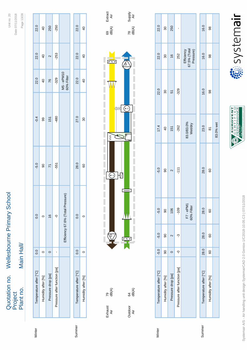
Quo
tatio
n no
.W
elle
sbou
rne
Prim
ary
Scho
olPr
ojec
tPl
ant n
o.M
ain
Hal
l/
Uni
t no.
20
Dat
e 07
/11/
2018
Page
13/
28
VVX
EF
MSF
Exha
ust
Air
79 dB(A
)Ex
tract
Air
69 dB(A
)
Supp
lyAi
r78 dB
(A)
Out
door
Air
64 dB(A
)
Hum
idity
afte
r [%
]0
060
3040
4040
Tem
pera
ture
afte
r [°C
]0.
00.
028
.027
.022
.022
.022
.0Su
mm
er
Effic
ienc
y 67
.6%
(Tot
al P
ress
ure)
M5
- ePM
1060
% F
ilter
Pres
sure
afte
r fun
ctio
n [p
a]-
-0-5
51-4
80-3
29-2
53-2
50
Pres
sure
dro
p [p
a]0
1671
151
762
250
Hum
idity
afte
r [%
]0
090
9940
4040
Tem
pera
ture
afte
r [°C
]0.
00.
0-5
.0-0
.422
.022
.022
.0W
inte
r
Win
ter
Tem
pera
ture
afte
r [°C
]-5
.0-5
.0-5
.0-5
.017
.422
.022
.022
.0
Hum
idity
afte
r [%
]90
9090
9040
3030
30
Pres
sure
dro
p [p
a]0
210
62
151
5116
250
Pres
sure
afte
r fun
ctio
n [p
a]-0
-3-1
09-1
11-2
62-3
2925
2-
F7 -
ePM
160
% F
ilter
83
.0/8
3.0%
Wet
/dry
Effic
ienc
y67
.5%
(Tot
alPr
essu
re)
Sum
mer
Tem
pera
ture
afte
r [°C
]28
.028
.028
.028
.023
.016
.016
.016
.0
Hum
idity
afte
r [%
]60
6060
6081
9898
98
83.0
% w
et
Syst
emai
r A/S
- Ai
r han
dlin
g un
it de
sign
Sys
tem
airC
AD 2
.0 G
enio
x-1/
C20
18-1
0.05
.C3
| 07/
11/2
018

Quotation no. Wellesbourne Primary SchoolProjectPlant no. Main Hall/
Unit no. 20
Date 07/11/2018
Page 14/28
Commissioning Data Supply Extract UnitPressure drop clean filters 47 30 PaFans absorbed power clean filters - - kW
Alternative working pointsDim./Max Average
Airflow, Supply, m³/s 1.40 1.40Airflow, Extract, m³/s 1.40 1.40External pressure drop, Supply 250External pressure, Extract 250SFPv, kW/(m³/s) 1.64 1.64SFPe, kW/(m³/s) 1.80 1.80Efficiency, Heat exchanger (wet), % 83.0 83.0Efficiency, Heat exchanger (dry), % 83.0 83.0Heat pump, Absorbed power, Winter, kW 1.8 1.8Heat pump, Absorbed power, Summer, kW 7.2 7.2Sound data dB(A)
Supply air 78Outdoor air 64Exhaust air 79Extract air 69
Sound break out 56Operation hours 8760
Operational hours yearly 8760
Systemair LtdUnit 28 Gravelly Ind ParkBirminghamB24 8HZ
Telephone :0121 322 [email protected]
Systemair A/S - Air handling unit design SystemairCAD 2.0 Geniox-1/C2018-10.05.C3 | 07/11/2018

Quotation no. Wellesbourne Primary SchoolProjectPlant no. Main Hall/
Unit no. 20
Date 07/11/2018
Page 15/28
Technical specification
Unit
Frequency band [Hz] 63 125 250 500 1K 2K 4K 8K TotalSound power level [dB] [dB] [dB] [dB] [dB] [dB] [dB] [dB] [dB(A)]Supply air 72 76 77 75 74 70 67 63 78Outdoor air 67 68 69 63 54 49 43 36 64Exhaust air 72 76 77 75 75 70 67 63 79Extract air 67 68 69 65 64 59 56 51 69Sound break out 65 65 55 51 52 46 41 27 56
CasingPanels Steel sheets coated with aluzinc AZ185Frame profiles Steel profiles coated with zinc z275 and powder coatedMullion profiles Steel profiles coated with aluzinc AZ185Corners ABSInsulation 60 mm mineral wool / Density 60 kg/m3Corrosion protection Class C4 according to EN ISO 12944-2:2000Operating pressure 0 - 2000 Pa (Geniox10 - Geniox31)
0 - 1500 Pa (Geniox36 - Geniox44)Operating temperatures -40/+40 °C (Standard)
-40/+60 °C (Special design)Classifications EN 1886, 2. edition 2008Mechanical Strength Class D1(M)Casing air leakage -400 Pa: Class L2(M)
+700 Pa: Class L2(M)Filter by-pass leakage -400 Pa: Class G1-F9
+400 Pa: Class G1-F9Thermal transmittance Class T2(M)Thermal bridging factor Class TB2(M)
Acoustic insulation of casing Octave band Hz Insulation dB63 10
125 17250 24500 27
1000 282000 284000 328000 40
Roof Trapezoidal roof plates - steelRoof dimensions (width x height x length) 1782 x 150 x 4182 mmRoof is built of trapezoidal steel plates coated with alu-zinc. The Slope of the roof is about 3° and there is an overhang of 100 – 200 mm along all 4 sides. The trapezoidal plates, profiles, screws and sealant are delivered as an assembly kit along with assembly instructions.
Systemair LtdUnit 28 Gravelly Ind ParkBirminghamB24 8HZ
Telephone :0121 322 [email protected]
Systemair A/S - Air handling unit design SystemairCAD 2.0 Geniox-1/C2018-10.05.C3 | 07/11/2018

Quotation no. Wellesbourne Primary SchoolProjectPlant no. Main Hall/
Unit no. 20
Date 07/11/2018
Page 16/28
Control systemLanguage in controller menu English
NaviPad navigation tablet delivered YesExternal communication BACnet, IPTemperature control Supply air temperature controlFan control Air flow control m³/hDamper motor supply air Motor spring returnDamper motor extract air Motor spring returnFor selection of sensors - study flow chart in control system printout
Mains power supply for control systemSwitch board data Supply cable L1 + L2 + L3 + N + PE
Voltage 3x400 VACHz 50 HzFuse for supply air fan (in main cabinet) 10 AFuse for extract air fan (in main cabint) 10 AFuse for DVU-HP (in cabinet for DVU-HP) 32 ARated fuse PSCC max (in main cabinet) 10 kAMax. consumed current 33.2 AMax. consumed current in neutral wire 5.0 AMinimum fuses for unit (L1-L2-L3) 40 AMinimum fuses for unit (L1-L2-L3-N) 40 A
The installer must ensure that protection of the mains power supply relating to frequency converters is according to local statutory requirements. By one or more 400 VAC motors, HPFI type B must be installed.
The electrical installation (wiring, mounting of components, connection plugs, etc.) for the unit is done as an machine installation according to 60204-1
The supply unit consist of
Empty sectionPressure drop 2 PaLength 300 mm
Damper Pressure drop 2 PaDamper blades Standard
Systemair LtdUnit 28 Gravelly Ind ParkBirminghamB24 8HZ
Telephone :0121 322 [email protected]
Systemair A/S - Air handling unit design SystemairCAD 2.0 Geniox-1/C2018-10.05.C3 | 07/11/2018

Quotation no. Wellesbourne Primary SchoolProjectPlant no. Main Hall/
Unit no. 20
Date 07/11/2018
Page 17/28
Filter Dimensioning pressure drop 106 PaInitial pressure drop/Final pressure drop 47/165 PaVelocity, face area 1.87 m/sVelocity, filter area 1.87 m/sFilter class F7 - ePM1 60%Filter length 520 mmFilter description Camfil Hi-Flo II XLT
Inspection sectionPressure drop 2 PaLength 100 mm
Rotary heat exchanger Supply Extract
Air flow 1.40 1.40 m³/sPressure drop 151 151 PaWINTERAir temperature before/after -5.0/17.4 22.0/-0.4 °CAir relative humidity before/after 90/40 40/99 %Capacity 49.60 kWTemperature efficiency 83.0 %Dry efficiency according to EN 308 at 1.40 m³/s 83.0 %Humidity efficiency 61.3 %SUMMERAir temperature before/after 28.0/23.0 22.0/27.0 °CAir relative humidity before/after 60/81 40/30 %Capacity 8.70 kWTemperature efficiency 83.0 %Humidity efficiency -0.2 %Heat exchanger type ST - Condensation (Temperature)Efficiency (Wave height) X - HighWheel Diameter Ø1280Description ST1-XL-WV-1280Rotor drive Variable speedElectrical data 1x230V, 40W, 0.7Amp
Purging sector 1 pcs
Systemair LtdUnit 28 Gravelly Ind ParkBirminghamB24 8HZ
Telephone :0121 322 [email protected]
Systemair A/S - Air handling unit design SystemairCAD 2.0 Geniox-1/C2018-10.05.C3 | 07/11/2018

Quotation no. Wellesbourne Primary SchoolProjectPlant no. Main Hall/
Unit no. 20
Date 07/11/2018
Page 18/28
Heat pumpSupply Extract
Air flow 1.40 1.40 m³/sPressure drop 51 71 PaFace velocity for the coil 2.1 2.1 m/s
WINTERAir temperature before/after * 17.4/22.0 -0.4/-2.8 °CAir relative humidity before/after 39.6/29.8 99.0/99.0 %Capacity * 7.9 6.5 kWRefrigerant temperature 26.4 -6.2 °CCondensate 0.1 l/minUsed capacity at working conditions 27.1 %Absorbed power, at operating point 1.8 kWCOP, compressor system * 4.5COP total, compressor system + rotary heat exchanger * 32.0* Energy for the defrosting is not considered in the winter calculation. The heat pumps cannot run continuously with refrigerant temperatures below -2°C without defrosting. The defrosting will cause temperature drop in the supply air for a short period.
SUMMERAir temperature before/after 23.0/16.0 27.0/46.3 °CAir relative humidity before/after 81.2/98.0 29.5/10.3 %Capacity 25.7 33.0 kWRefrigerant temperature 10.7 50.5 °CSensible cooling in % of total cooling 46 %Condensate 0.3 l/minUsed capacity at working conditions 74.6 %Absorbed power, at operating point 7.2 kWEER, compressor system 3.6EER total, compressor system + rotary heat exchanger 4.7
Tube material Cu CuFin material Al AlFin spacing 2.5 2.5 mmCode for supply air coil TDZ-14-CD-Z-5-9-575-1158-2.5-Cu-Al-H-7/8Code for extract air coil TCZ-14-CD-Z-6-6-575-1158-2.5-Cu-Al-V-7/8Drip tray material Stainless steel Stainless steelRefrigerant / Amount R410A 8.3 kgCompressor ZPD61+ZP61External connectionsCurrent (is included in the main cabinet) 3*400V+N+PE, 50Hz 23.6 AStart signal (Heating) / Cooling demand Potential free contact setControl signal 0 - 10 V,DCPotential-free alarm signal 1 pcs
Systemair LtdUnit 28 Gravelly Ind ParkBirminghamB24 8HZ
Telephone :0121 322 [email protected]
Systemair A/S - Air handling unit design SystemairCAD 2.0 Geniox-1/C2018-10.05.C3 | 07/11/2018

Quotation no. Wellesbourne Primary SchoolProjectPlant no. Main Hall/
Unit no. 20
Date 07/11/2018
Page 19/28
Fan , PlugAir flow 1.40 m³/sExternal pressure 250 PaPressure drop 16 PaStatic pressure (Designed at wet conditions) 581 PaTotal pressure 614 PaFan speed 1597 RPMMaximum fan speed 1880 RPMTotal efficiency by static pressure, incl. motor and speed control 64.0 %Total efficiency by total pressure, incl. motor and speed control 67.5 %K-factor (p=1.2 kg/m³) 197Fan type - Large GR45C-ZIK.DG.CRErP efficiency n(stat,A) 69.0 %ErP efficiency class N(actual)/ N(target) 76.3 / 62ErP-conformity YesDirect drive
MotorMotor type EC motorMotor types-size ZIK.DG.CRMotor protection Built-inRated power 2.00 kWSpeed (nominal) 1880 RPMCurrent, Amp. 3.30 AVoltage 3x400 VConsumed power from mains power supply, including speed control 1.27 kW
Safety screen 1 pcs
Empty sectionPressure drop 2 PaLength 300 mm
The extract unit consist of
Damper Pressure drop 2 PaDamper blades Standard
Systemair LtdUnit 28 Gravelly Ind ParkBirminghamB24 8HZ
Telephone :0121 322 [email protected]
Systemair A/S - Air handling unit design SystemairCAD 2.0 Geniox-1/C2018-10.05.C3 | 07/11/2018

Quotation no. Wellesbourne Primary SchoolProjectPlant no. Main Hall/
Unit no. 20
Date 07/11/2018
Page 20/28
Filter Dimensioning pressure drop 76 PaInitial pressure drop/Final pressure drop 30/122 PaVelocity, face area 1.87 m/sVelocity, filter area 1.87 m/sFilter class M5 - ePM10 60%Filter length 520 mmFilter description Camfil Hi-Flo II XLT
Heat pumpData are stated on supply.
Rotary heat exchanger Data are stated on supply.
Fan , PlugAir flow 1.40 m³/sExternal pressure 250 PaPressure drop 16 PaStatic pressure (Designed at wet conditions) 567 PaTotal pressure 600 PaFan speed 1584 RPMMaximum fan speed 1880 RPMTotal efficiency by static pressure, incl. motor and speed control 63.9 %Total efficiency by total pressure, incl. motor and speed control 67.6 %K-factor (p=1.2 kg/m³) 197Fan type - Large GR45C-ZIK.DG.CRErP efficiency n(stat,A) 69.0 %ErP efficiency class N(actual)/ N(target) 76.3 / 62ErP-conformity YesDirect drive
MotorMotor type EC motorMotor types-size ZIK.DG.CRMotor protection Built-inRated power 2.00 kWSpeed (nominal) 1880 RPMCurrent, Amp. 3.30 AVoltage 3x400 VConsumed power from mains power supply, including speed control 1.24 kW
Safety screen 1 pcs
Systemair LtdUnit 28 Gravelly Ind ParkBirminghamB24 8HZ
Telephone :0121 322 [email protected]
Systemair A/S - Air handling unit design SystemairCAD 2.0 Geniox-1/C2018-10.05.C3 | 07/11/2018

Quotation no. Wellesbourne Primary SchoolProjectPlant no. Main Hall/
Unit no. 20
Date 07/11/2018
Page 21/28
Outlet on the back side of unitPressure drop 0 Pa
Other parts
Feet or baseframeFeet or baseframe BaseframeBaseframe height 218 mmCorrosion protection Galvanized Z275
Inlet louvreProduct Dimensions (width x height)Outdoor 1400x600 mmSupply 1400x600 mmExtract 1400x600 mmExhaust 900x700 mm
Section about shipping
Product Dimensions (width x height x length), Weight, Inc. Packaging Weight of unitincl. packaging
AHU1-4182 1582 x 1820 x 4182 mm 1469 kg 1466 kgThe unit sections are delivered mounted on base frame.
GXroof-14-4990-1 2200 x 300 x 1200 mm 83 kg 65 kgThe trapezoidal plates, profiles, screws and sealant are delivered as an assembly kit along with assembly instructions.
Systemair LtdUnit 28 Gravelly Ind ParkBirminghamB24 8HZ
Telephone :0121 322 [email protected]
Systemair A/S - Air handling unit design SystemairCAD 2.0 Geniox-1/C2018-10.05.C3 | 07/11/2018

Quotation no. Wellesbourne Primary SchoolProjectPlant no. Main Hall/
Unit no. 20
Date 07/11/2018
Page 22/28
Weights
Section No Section Code Weight of function Weight of sectionFunction Code kg kg
1 Casing Length 1241 mm 300Casing 214Empty section 0.1Damper 17Filter 14Inspection section 0.1Fan 54Outlet on the back side of unit 0.1
2 Casing Length 1400 mm 726Rotary heat exchanger 126Integrated cooling 600
3 Casing Length 1141 mm 290Casing 197Fan 54Empty section 0.1Control system 8Damper 17Filter 14
4 Baseframe Length 3782 mm 130Other components 85Weight of unit 1531
Systemair LtdUnit 28 Gravelly Ind ParkBirminghamB24 8HZ
Telephone :0121 322 [email protected]
Systemair A/S - Air handling unit design SystemairCAD 2.0 Geniox-1/C2018-10.05.C3 | 07/11/2018

Quotation no. Wellesbourne Primary SchoolProjectPlant no. Main Hall/
Unit no. 20
Date 07/11/2018
Page 23/28
Integrated Systemair Access control system
The air handling unit is built with a complete and fully integrated control system - based on the Access control unit mounted in the control cabinet and the NaviPad control panel with a graphical user interface. The air handling unit can either run stand alone or handled from a building management system.Before shipment the unit has been assembled and has passed a final functional test and inspection. Order-specific parameters are stored in the control unit during this process. The test report is delivered with the air handling unit.
Flow chart
VVX
P
BP2:AGQ2
EF
T
BT2 TA2
M
P
BP1:B
M
QM32S
T
BT3
M
QM31S
T
BT1
P
BP2:B
M
DVU HP
T
BT4
P
BP1:A GQ1
SF
T
BT5Components in red are not delivered
Exhaust
Outdoor
Extract
Supply
Detailed technical specificationSymbol Cable Page/ Terminals HW I/O
External components Name number ColumnSupply air tempemperature BT5 W355 13 : 3 T11 AI1Normal speed Ext. Sig. W581 10 : 2 T31 DI2Reduced speed W580 10 : 1 T32 DI1Unit stop W583 10 : 4 T30 DI3
Internal componentsRotor drive TA2 W232 36 : 7 F3: L1-N
W642 36 : 8 Link 2 BUS Adr. 7Temperature efficiency BT4 W343 30 : 1 BP1 DPT BP1: In2Damper motor on/off spring return, supply QM31S W631 34 : 1 Link 1 BUS Adr. 21Pressure over filter, supply BP2:B W662 DPT BP2: BOutdoor air temperature BT1 W341 31 : 1 BP2 DPT BP2: In1
Systemair LtdUnit 28 Gravelly Ind ParkBirminghamB24 8HZ
Telephone :0121 322 [email protected]
Systemair A/S - Air handling unit design SystemairCAD 2.0 Geniox-1/C2018-10.05.C3 | 07/11/2018

Quotation no. Wellesbourne Primary SchoolProjectPlant no. Main Hall/
Unit no. 20
Date 07/11/2018
Page 24/28
Pressure transmitter - supply fan BP1:A W661 30 : 1 Link 1 BUS Adr. 5EC fan, supply 1 GQ1 W601 32 : 0 Link 1 BUS Adr. 1
W101 25 : 2 F1: L1-L2-L3DVU-HP DVU HP W529
W528 10 : 5 T29 (X5:25-26) DI414 : 3 T62 (X5:18-19) DO210 : 7 T28 (C9-NO9) DI515 : 4 T66 (X5:17-18) DO616 : 4 T72 AO2
Damper motor on/off spring return, extract QM32S W632 35 : 1 Link 2 BUS Adr. 22Pressure over filter, extract BP1:B W661 DPT BP1: BExtract temperature BT3 W444 30 : 1 BP1 DPT BP1: In1Exhaust/De-ice temperature BT2 W442 31 : 2 BP2 DPT BP2: In2Pressure transmitter - extract fan BP2:A W662 31 : 1 Link 2 BUS Adr. 6EC fan, extract 1 GQ2 W602 33 : 0 Link 2 BUS Adr. 2
W102 26 : 2 F2: L1-L2-L3
Control cabinet and mains supply
The control cabinet is placed as indicated in order confirmation material. The control cabinet holds necessary components including terminal blocks, fuses, 24VDC power supply and the Access control unit. The controller is configured according to the customer’s order and confirmed in the order confirmation. Specification is also delivered with the unit. On site mains power supply must be connected to the cabinet. The installer on site has full responsibility to ensure that any unit/installation which requires additional protection of the mains power supply relating to frequency converters or any other such device is all carried out according to local statutory requirements.The supply disconnecting device for the unit is not included.
External electrical components
Temperature sensor for the supply air is delivered with 10 metres of cable, and must be connected to the terminals in the control cabinet by the installer on site.The Access control unit is prepared for connection of delivered components and extra sensors that could be needed.Control panel with 3 m cable is not connected to controller.Depending on the customer’s choice, external components are delivered, such as:• pressure transmitters in ducts for pressure control• valve for heating with heating coil• temperature sensor for frost protection of the hot water heating coil• electrical heating coil• valve for cooling with chilled water.NaviPad control panel with 3 m cable is not connected to the Access control unit from the factory.
Systemair LtdUnit 28 Gravelly Ind ParkBirminghamB24 8HZ
Telephone :0121 322 [email protected]
Systemair A/S - Air handling unit design SystemairCAD 2.0 Geniox-1/C2018-10.05.C3 | 07/11/2018

Quotation no. Wellesbourne Primary SchoolProjectPlant no. Main Hall/
Unit no. 20
Date 07/11/2018
Page 25/28
Access control unit and NaviPad control panel.
The Navipad control panel with 7” capacitive touch panel and 3 m cable must be connected to the Access CU40-C control unit in the control cabinet. All normal handling and configuration is carried out from the graphical user interface on the NaviPad control panel. The protection class of the NaviPad control panel is IP 54 and 0-50 C° permitted temperature. The NaviPad enclosure is not UV resistant and the NaviPad is not for outdoor mounting. Communication between the panel and the controller in the cabinet is possible with up to 100 meters of cable. The installer must use Standard PDS LAN network cable AWG23 (path cable) for extension.If several units are connected to a local network (on the same subnet), the NaviPad will be able to connect and monitor up to nine units. Please see separate instruction for detailsIf more units are connected to a local network (same subnet), the panel will be able to connect and handle up to nine units. Please see separate instruction for details
Schedules
The controller has individual schedules for start, stop and normal/reduced/high airflow rate for each weekday as well as schedules for holidays.The controller has automatic summer-winter-time change over.Outside normal operating hours, free cooling is available according to settings.
Cooling recovery
If the extract air temperature is lower than the outdoor air temperature, and there is a cooling demand in the rooms, the cooling recovery will be activated. The heat exchanger signal is reversed to give increasing cooling recovery on increasing demand.
Access rights - passwords
There are 3 different user levels• End-user - (no password) - access to read values on the start page, see the flow diagram, possibility
to start/stop the unit, adjust the temperature setpoint and activate extended running.• Operator level (password) - access to read values, change user relevant settings concerning
schedules, temperature, air flow and also to acknowledge alarms and to restart the system after having removed the reason that triggered the alarm.
• Service (special password) - access to make changes in configuration menus, access to store new settings, access to restart the unit according to user’s own settings or original factory settings.
Alarms and safety functions
If an alarm condition occurs, a circular light appear at the bottom of the control panel.• Fixed green — Status ok (no active alarms).• Flashing red — Active/returned alarms in one or more controllers.• Fixed red — Acknowledged/blocked alarms in one or more controllers, alarms not reset
Systemair LtdUnit 28 Gravelly Ind ParkBirminghamB24 8HZ
Telephone :0121 322 [email protected]
Systemair A/S - Air handling unit design SystemairCAD 2.0 Geniox-1/C2018-10.05.C3 | 07/11/2018

Quotation no. Wellesbourne Primary SchoolProjectPlant no. Main Hall/
Unit no. 20
Date 07/11/2018
Page 26/28
Alarms are logged in an alarm list. The list shows the type of alarm, date and time for the alarm and alarm class:• Class A alarm• Needs to be acknowledged• Class B alarm• Needs to be acknowledged• Class C alarm• Returns when the cause of the alarm disappear
Flexible System
A qualified service technician - on the site and at the request of the user - will be able to adapt the regulation further to the requirements of the users;• The air flow regulation can be changed between several methods that are constant air volume through
the fans, constant pressure in the ducts, CO2 dependant control or humidity dependant control. Temperature controlled airflow, which either decrease or increase airflow to achieve heating or cooling demand.
• The temperature control mode can be changed between room temperature control, supply air temperature control, extract temperature control and outdoor compensation of the selected temperature. Summer/winter dependent switching between extract air/room temperature control and supply air temperature control.
• In addition to the fixed schedule, an external start signal for extended operation is available, 3 levels• In addition or as an alternative to the fixed schedule, an external stop input signal is available.• A large number of other alternative functions are also optional.
Recovery with rotary heat exchanger
The capacity of the rotary heat exchanger is steplessly controlled via the modulated control of rotor speed.
Extended running - normal, reduced speed, high speed and stop
Extended running can be activated in 3 ways:• Digital input for normal, reduced, high, stop.• From the start page of the NaviPad at normal speed.• Signal from BMS system for normal, reduced, high, stop.
Systemair LtdUnit 28 Gravelly Ind ParkBirminghamB24 8HZ
Telephone :0121 322 [email protected]
Systemair A/S - Air handling unit design SystemairCAD 2.0 Geniox-1/C2018-10.05.C3 | 07/11/2018
Quotation no. Wellesbourne Primary SchoolProjectPlant no. Main Hall/
Unit no. 20
Date 07/11/2018
Page 27/28
Communication to BMS systems via BACnet, IP
The controller has been prepared for BACnet via TCP/IP (LAN).This can be used for communication with a BMS system (Building Management System).
Supply air temperature control
• The control of the supply air temperature is based on the value from the sensor mounted in the supply air duct.
The supply air temperature is controlled by a PID-controller (PID control loop). The set-point for the supply temperature can be adjusted from the control panel.
Air flow control - m3/h, l/s, m3/s, CFM
The air flow rates of supply and extract air are controlled separately. The supply and extract air at low, normal, high airflow are set separately on the control panel.On each fan a pressure transmitter measures the difference between the pressure before the fan and the pressure at the measuring probe in the inlet cone. Through a formula with a factor for each fan size, the output signal from the pressure transmitter is used to calculate the actual airflow.A PID-controller maintains the set point value by controlling the speed of the fans.
Supply fan with EC motor
The supply air fan is driven by an EC motor with the impeller mounted directly on the motort. All parameters in the motor speed control have been configured and tested from factory.
Extract fan with EC motor
The extract air fan is driven by an EC motor with the impeller mounted directly on the motor. All parameters in the motor speed control have been configured and tested from factory.
GXU-HP compressor system with cooling recovery, cooling and heating function
The complete compressor system is in a separate section with rotary heat exchanger, coils and the system for the control of safety functions as well as the capacity. The system is able to provide cooling or heating of the supply air.The main controller in the cabinet for the air handling unit delivers a start/stop signal and 0-10V DC signal for control of the capacity between 5 % and 100 %. The separate controller in this section converts the signal to the capacity required.To promote maximum reliability, the system has an automatic capacity reduction system for reduction of the risk of cut off due to overheating. The system is provided with refrigerant and tested for easy start up on the site.The power supply for the compressor system is delivered from the main cabinet for the air handling unit.The main controller in the cabinet for the air handling unit is able to control the cooling recovery by the rotary heat exchanger with the advantage that the outdoor air is precooled by the rotary heat exchanger,
Systemair LtdUnit 28 Gravelly Ind ParkBirminghamB24 8HZ
Telephone :0121 322 [email protected]
Systemair A/S - Air handling unit design SystemairCAD 2.0 Geniox-1/C2018-10.05.C3 | 07/11/2018

Quotation no. Wellesbourne Primary SchoolProjectPlant no. Main Hall/
Unit no. 20
Date 07/11/2018
Page 28/28
when the extract air temperature is lower than the outdoor air temperature. Due to the reduced outdoor air temperature before the cooling coil, the electricity consumption of the compressor system is reduced. The condenser is in the extract airflow after the rotary heat exchanger.
Damper motors
Supplied and installed as in flow chart specification. Spring return models (S) will have running time of about 150/16 seconds. Non spring about 150 seconds. Modulated models indicated by round symbol.
Filter guards
Filter guards over bag filters are modulated. Pressure limit is depending on the flow. Low flow = low pressure limit, high flow = high limit. Transmitters are connected to the controller. From the display you can see actual pressure and set limits for alarm. Transmitters placed as indicated in flow chart.Panel filter will have a pressure switch to give signal to the controller when set limit is exceeded.
Cabinet integrated in or on Geniox 10-18
The cabinet is integrated in or on the air handling unit according to the technical documentation.Indoor units with external cabinet will have external cabling connected to the cabinet with plug connectors. Cables are to be covered by ready to mount ducting, delivered with the unit.Units with horizontal section split, size GX10-16 will have ducting partly at the backside of the unit. Size GX18, cables are to be run in a covered cable tray at the front of the unit.All units with integrated cabinet, will have internal cabling. At vertical section split, assembled by pre-mounted connectors.
Systemair LtdUnit 28 Gravelly Ind ParkBirminghamB24 8HZ
Telephone :0121 322 [email protected]
Systemair A/S - Air handling unit design SystemairCAD 2.0 Geniox-1/C2018-10.05.C3 | 07/11/2018

Noise Assessment
Warwickshire County Council A112162
Wellesbourne Primary School April 2019
Appendix F – Comments Response to EHO – 07th March
2019
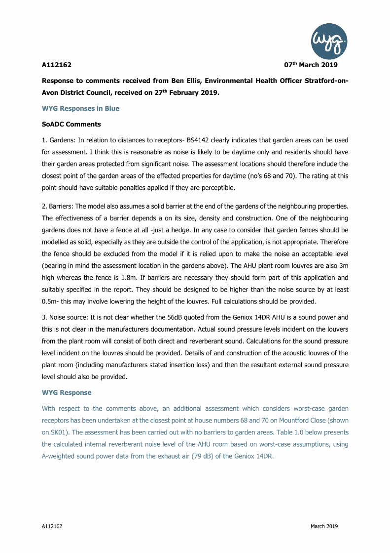
A112162 March 2019
A112162 07th March 2019
Response to comments received from Ben Ellis, Environmental Health Officer Stratford-on-
Avon District Council, received on 27th February 2019.
WYG Responses in Blue
SoADC Comments
1. Gardens: In relation to distances to receptors- BS4142 clearly indicates that garden areas can be used
for assessment. I think this is reasonable as noise is likely to be daytime only and residents should have
their garden areas protected from significant noise. The assessment locations should therefore include the
closest point of the garden areas of the effected properties for daytime (no’s 68 and 70). The rating at this
point should have suitable penalties applied if they are perceptible.
2. Barriers: The model also assumes a solid barrier at the end of the gardens of the neighbouring properties.
The effectiveness of a barrier depends a on its size, density and construction. One of the neighbouring
gardens does not have a fence at all -just a hedge. In any case to consider that garden fences should be
modelled as solid, especially as they are outside the control of the application, is not appropriate. Therefore
the fence should be excluded from the model if it is relied upon to make the noise an acceptable level
(bearing in mind the assessment location in the gardens above). The AHU plant room louvres are also 3m
high whereas the fence is 1.8m. If barriers are necessary they should form part of this application and
suitably specified in the report. They should be designed to be higher than the noise source by at least
0.5m- this may involve lowering the height of the louvres. Full calculations should be provided.
3. Noise source: It is not clear whether the 56dB quoted from the Geniox 14DR AHU is a sound power and
this is not clear in the manufacturers documentation. Actual sound pressure levels incident on the louvers
from the plant room will consist of both direct and reverberant sound. Calculations for the sound pressure
level incident on the louvres should be provided. Details of and construction of the acoustic louvres of the
plant room (including manufacturers stated insertion loss) and then the resultant external sound pressure
level should also be provided.
WYG Response
With respect to the comments above, an additional assessment which considers worst-case garden
receptors has been undertaken at the closest point at house numbers 68 and 70 on Mountford Close (shown
on SK01). The assessment has been carried out with no barriers to garden areas. Table 1.0 below presents
the calculated internal reverberant noise level of the AHU room based on worst-case assumptions, using
A-weighted sound power data from the exhaust air (79 dB) of the Geniox 14DR.

A112162 March 2019
Table 1.0 Calculated Reverberant Noise Level
BSP Unit 63 125 250 500 1K 2K 4K 8K
Length 5.8 5.8 5.8 5.8 5.8 5.8 5.8 5.8
Width 2.3 2.3 2.3 2.3 2.3 2.3 2.3 2.3
Height 3 3 3 3 3 3 3 3
RT 1.5 1.5 1.5 1.5 1.5 1.5 1.5 1.5
r distance from source to nearest internal facade
1 1 1 1 1 1 1 1
Q Directivity 4 4 4 4 4 4 4 4
Lw 45.8 59.9 68.4 71.8 75.0 71.2 68.0 61.9
Volume of Space 40.0 40.0 40.0 40.0 40.0 40.0 40.0 40.0
Surface Areas 75.3 75.3 75.3 75.3 75.3 75.3 75.3 75.3
A Total Absorption
4.3 4.3 4.3 4.3 4.3 4.3 4.3 4.3
Alpha bar 0.7 0.7 0.7 0.7 0.7 0.7 0.7 0.7
Rc Room Constant
175.7 175.7 175.7 175.7 175.7 175.7 175.7 175.7
SPL 41 55 64 67 70 67 63 57
Calculated Reverberant SPL Based on Number
of Sources
41.0 55.0 64.0 67.0 70.0 67.0 63.0 57.0
Sound Pressure Level 74.0
Details of the acoustic louvre doors (Metador Defender Soundguard) for the AHU plant room are appended
to this document. It has been confirmed that the 300mm deep Sound Block Louvre System single figure
sound reduction of Rw 18 dB is to be used. As shown within the manufacturers specification attached,
spectrum data is not available. However, with this attenuation, the output from the AHU with the above
reverberant calculations is 56 dB (A), the same as the breakout sound power level detailed within the
manufacturer’s data for the Geniox 14DR.
The assessment of noise levels within the closest point of gardens 68 and 70 on Mountford Close is shown
in the table below. The BS4142:2014 assessment is inclusive of a +2 dB correction in accordance with the
previous assessment.
Table 2.0 Noise Assessment for Proposed BSP in Gardens
Ref
Measured Average Pre-installation Background LA90
Specific noise level from plant LAeq
Noise Rating Level from Plant LAeq
BS 4142 Score
Daytime Daytime Daytime Daytime
G01 42 43 45 3
G02 42 42 44 2
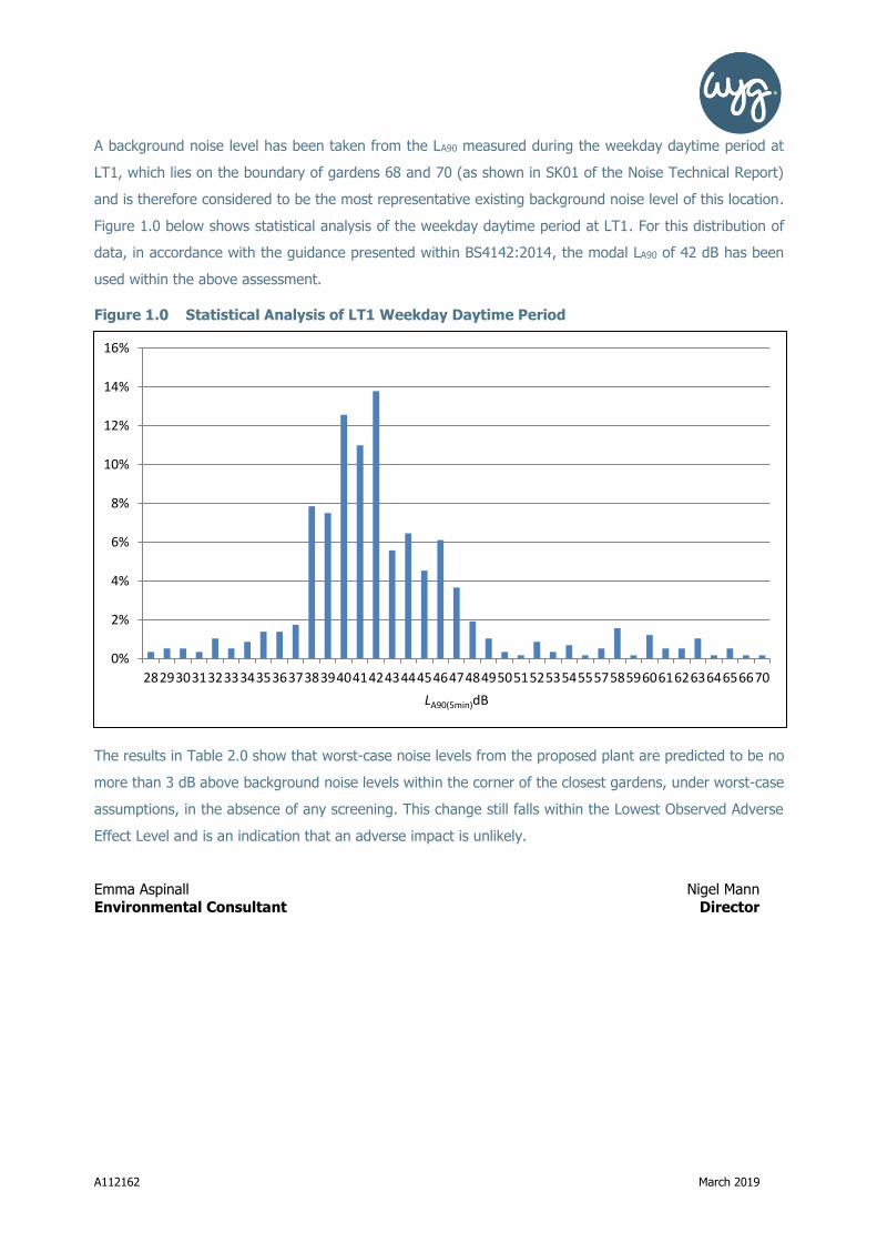
A112162 March 2019
A background noise level has been taken from the LA90 measured during the weekday daytime period at
LT1, which lies on the boundary of gardens 68 and 70 (as shown in SK01 of the Noise Technical Report)
and is therefore considered to be the most representative existing background noise level of this location.
Figure 1.0 below shows statistical analysis of the weekday daytime period at LT1. For this distribution of
data, in accordance with the guidance presented within BS4142:2014, the modal LA90 of 42 dB has been
used within the above assessment.
Figure 1.0 Statistical Analysis of LT1 Weekday Daytime Period
The results in Table 2.0 show that worst-case noise levels from the proposed plant are predicted to be no
more than 3 dB above background noise levels within the corner of the closest gardens, under worst-case
assumptions, in the absence of any screening. This change still falls within the Lowest Observed Adverse
Effect Level and is an indication that an adverse impact is unlikely.
Emma Aspinall Nigel Mann
Environmental Consultant Director
0%
2%
4%
6%
8%
10%
12%
14%
16%
282930313233343536373839404142434445464748495051525354555758596061626364656670
LA90(5min)dB

A112162 March 2019
Appendices
Sketches
SK01 Garden Receptor Locations and Worst-case LAeq Noise Contour Plot

G01
G02
428160
428160
428180
428180
428200
428200
428220
428220
428240
428240
428260
428260
428280
428280
428300
428300
428320
428320
428340
428340
428360
428360
428380
428380
428400
428400
428420
428420
428440
428440
428460
428460
428480
428480
428500
428500
428520
428520
428540
428540
428560
428560
428580
4285802
55
42
0
25
54
20
25
54
40
25
54
40
25
54
60
25
54
60
25
54
80
25
54
80
25
55
00
25
55
00
25
55
20
25
55
20
25
55
40
25
55
40
25
55
60
25
55
60
25
55
80
25
55
80
25
56
00
25
56
00
25
56
20
25
56
20
25
56
40
25
56
40
25
56
60
25
56
60
25
56
80
25
56
80
25
57
00
25
57
00
25
57
20
25
57
20
25
57
40
25
57
40
Client:
Warwickshire CountyCouncil
Project:
Wellesbourne PrimarySchool
Project Number:
A112162
Drawing Title / Scenario:
Garden Receptor Locationsand Worst-case LAeq NoiseContour Plot
Drawing Number:
SK01
Key:
Site Boundary:
0.0 - 40.0 dB 40.0 - 50.0 dB 50.0 - 60.0 dB > 60.0 dB
Scale : Not to scale
WYGE Leicester 05.03.19
This map is based upon Ordnance Survey material reproducedby WYG on behalf of Her Majesty's Stationery Office, © Crown Copyright. Unauthorised reproduction infringesCrown copyright and may lead to civil proceedings.
Licence Number AL 553611
Executive ParkAvalon WayAnsteyLeicestershireLE7 7GRTel 0116 234 8000
© WYG Environment

A112162 March 2019
Acoustic Louvre Details

Defender SoundguardDesigned to reduce sound transmittance and keep your premises totally secure, Soundguard can be fully customised to meet your acoustic requirements.
ACOUSTIC

DDA Compliant
Britannia House, John Boyle Road, Middlesbrough, TS6 6TY
T 01642 337119F 0845 3710404
Visit our website www.metador.com
Follow us on Twitter @madebymetador
Structural opening sizes (mm)**
Max width Max height
Single leaf 1480 3050
Double leaf 2800 3050
The Defender Soundguard is designed to reduce sound transmittance for many external and internal applications. It is available in almost any size and is manufactured to suit the customer requirements. It has been designed to block sound up to Rw52dB.
Over panels / Side panelsAvailable to suit customer requirements.
Door Leaf
Manufactured from two 1.5mm Galvanised steel skins, folded and mechanically fixed to form a strong and rigid 45mm thick door leaf, filled with a variety of acoustic cores. Anti-jemmy flanges to the leading edge of the leaf provide excellent jemmy resistance.
Frame
90mm frames are pressed from 2mm Galvanised* steel to form a single rebated profile. Profiled headers form a smooth butt joint with the vertical posts and are joined together utilising strong M8 bolts to provide positive rigidity. The special fast fit frame is able to compensate for most irregularities in the opening with 8no threaded fixing adjusters per doorset. They permit a tolerance of up to 18mm on each side of the door. Shims and packers are not necessary making an extremely secure fix. Frames can be insulated if required.
Thresholds
DDA compliant 2mm stainless steel threshold bolted into the vertical frame posts. Available in outward opening, inward opening and ramped. An auto drop-seal is added for sound reduction for certain sound levels.
Seal
A variety of different acoustic perimeter seal systems available to meet your sound reduction requirements.
Hardware
Door leaves are hung from 4no stainless steel hinges for smooth operation and optimum weather resistance. Security dog bolts secure the leaf into the frame if the hinges are attacked. Additional hardware includes a range of locks, latches, lever handles, panic hardware, closers and stays. On double doors, lever-action flush bolts can be installed within the leading edge of the inactive door leaf.
Finish
Available in any RAL or BS standard or marine-grade powder-coat finishes.
Vision Panels
A full range of vision panels with acoustic glass with varying sound reduction levels.
Acoustic Door Louvres
Sound Block Louvre System
An acoustic louvre is somewhat of a contradiction in terms; a louvre is designed to allow the passage of air through a door, but at the same time it will permit the passage of sound. The SBLS is designed to reduce the amount of sound passing through the door whilst still allowing air to flow. In acoustic tests, our 300mm deep SBLS louvre has achieved a sound reduction of Rw18dB, and the 600mm deep SBLS louvre Rw32dB. Louvre panels to any sizes are available. Both solid, louvred and glazed over panels and side panels can be manufactured to suit individual customer requirements.*
Acoustic
* Magnelis steel is offered as an alternative. Please enquire.
** For oversized doors, please enquire.