Warranty Certificate - VIGAS · Warranty Certificate VIMAR 2018 Ver.D 2.00 ... VIGAS 12 DPA, VIGAS...
40
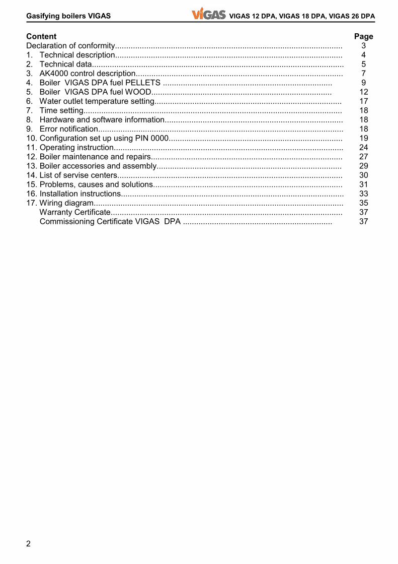
1 VIGAS 12 DPA, VIGAS 18 DPA, VIGAS 26 DPA Gasifying boilers VIGAS Gasifying boilers MANUAL FOR INSTALLATION, ASSEMBLY, MAINTENANCE AND USE Warranty Certificate VIMAR 2018 Ver.D 2.00 VIGAS 12 DPA, 18 DPA, VIGAS 26 DPA with AK4000 control
Transcript of Warranty Certificate - VIGAS · Warranty Certificate VIMAR 2018 Ver.D 2.00 ... VIGAS 12 DPA, VIGAS...
1
VIGAS 12 DPA, VIGAS 18 DPA, VIGAS 26 DPA Gasifying boilers VIGAS Gasifying boilers MANUAL FOR INSTALLATION, ASSEMBLY, MAINTENANCE AND USE Warranty Certificate
VIMAR 2018Ver.D 2.00
VIGAS 12 DPA, 18 DPA, VIGAS 26 DPA with AK4000 control
2
Gasifying boilers VIGAS VIGAS 12 DPA, VIGAS 18 DPA, VIGAS 26 DPA
Content Declaration of conformity...................................................................................................... 1. Technical description...................................................................................................... 2. Technical data................................................................................................................. 3. AK4000 control description............................................................................................. 4. Boiler VIGAS DPA fuel PELLETS ............................................................................ 5. Boiler VIGAS DPA fuel WOOD................................................................................. 6. Water outlet temperature setting.................................................................................... 7. Time setting.................................................................................................................... 8. Hardware and software information................................................................................ 9. Error notification.............................................................................................................. 10. Configuration set up using PIN 0000.............................................................................. 11. Operating instruction....................................................................................................... 12. Boiler maintenance and repairs...................................................................................... 13. Boiler accessories and assembly................................................................................... 14. List of servise centers..................................................................................................... 15. Problems, causes and solutions..................................................................................... 16. Installation instructions.................................................................................................... 17. Wiring diagram................................................................................................................ Warranty Certificate........................................................................................................ Commissioning Certificate VIGAS DPA ................................................................... Page 3 4 5 7 9 12 17 18 18 18 19 24 27 29 30 31 33 35 37 37
3
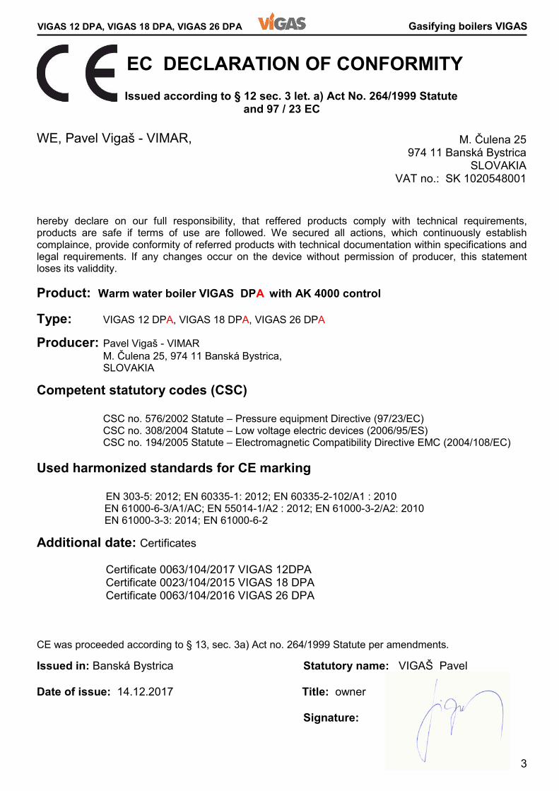
VIGAS 12 DPA, VIGAS 18 DPA, VIGAS 26 DPA Gasifying boilers VIGAS EC DECLARATION OF CONFORMITY Issued according to § 12 sec. 3 let. a) Act No. 264/1999 Statute and 97 / 23 EC WE, Pavel Vigaš - VIMAR, hereby declare on our full responsibility, that reffered products comply with technical requirements, products are safe if terms of use are followed. We secured all actions, which continuously establish complaince, provide conformity of referred products with technical documentation within specifications and legal requirements. If any changes occur on the device without permission of producer, this statement loses its validdity. Product: Warm water boiler VIGAS DPA with AK 4000 control Type: VIGAS 12 DPA, VIGAS 18 DPA, VIGAS 26 DPA Producer: Pavel Vigaš - VIMAR M. Čulena 25, 974 11 Banská Bystrica, SLOVAKIA Competent statutory codes (CSC) CSC no. 576/2002 Statute – Pressure equipment Directive (97/23/EC) CSC no. 308/2004 Statute – Low voltage electric devices (2006/95/ES) CSC no. 194/2005 Statute – Electromagnetic Compatibility Directive EMC (2004/108/EC) Used harmonized standards for CE marking EN 303-5: 2012; EN 60335-1: 2012; EN 60335-2-102/A1 : 2010 EN 61000-6-3/A1/AC; EN 55014-1/A2 : 2012; EN 61000-3-2/A2: 2010 EN 61000-3-3: 2014; EN 61000-6-2 Additional date: Certificates Certificate 0063/104/2017 VIGAS 12DPA Certificate 0023/104/2015 VIGAS 18 DPA Certificate 0063/104/2016 VIGAS 26 DPA CE was proceeded according to § 13, sec. 3a) Act no. 264/1999 Statute per amendments. Issued in: Banská Bystrica Statutory name: VIGAŠ Pavel Date of issue: 14.12.2017 Title: owner Signature:
M. Čulena 25 974 11 Banská Bystrica SLOVAKIA VAT no.: SK 1020548001
4
Gasifying boilers VIGAS VIGAS 12 DPA, VIGAS 18 DPA, VIGAS 26 DPA 1. TECHNICAL DESCRIPTION Combined warm water boiler VIGAS DPA offers two different systems of fuel combustion. Wood fuel combustion provides effective way applied with all Vigas boilers. Pellet fuel heating is provided by classic burning process on fire grate, made of heat resistant steel, where pellets are delivered by screw feeder. Boiler VIGAS 18 DPA and VIGAS 26 DPA is designed to burn pellets with diameter of 6 mm and lenght up to 40mm, as well as dry wood materials from sawdust to wood logs of 52 (VIGAS 12 DPA 37 cm) cm long, with max. diameter 20 cm. Sawdust, woodchips and cuttings are recommended to burn together with wood logs. Boilers are welded from 4 and 6 mm steel sheets. Inner boiler sheets, which are in contact with boiler gases are 6 mm thick, others are made of 4 mm steel. The heat exchanger is welded from 57 x 4,5 mm steel pipes. External casing of is made of 0,8 mm steel sheets. Heat insulation of the boiler is formed by 20-50 mm mineral wool. The combustion gas is discharged through steel flue gas into the chimney.The pellet container is designed from 1,5 mm steel sheet and its volume is 225L for 12DPA, 250 L for 18DPA, 340 L for 26DPA.The integral components of the boiler include: front gear unit, electric ignition unit, security tourniquet, air distributor with servo and fan, chimney temperature sensor, ultrasound sensor to detect level of pellets. Internal space consists of combustion chamber, where fuel is dried and combusted. Produced wood gas is carried through nozzle into combustion chamber, where it burns with support od secondary air. Pellets are led directly to combustion chamber by accurate dosing from container during combustion with assistance or regulated air supply. Furthermore, the flue gases are led to double-row heat exchanger, where intensively cooling down untill reaching the flue gas. Unburned ashes and waste is seated in the combustion chamber, which is advised to be clean approximately once a week. Boiler offers simple maintenance due to AK4000 control, located on the top of the boiler. Control AK4000 offers and permits following actions: � to control heating temperature reached by changing of fan speed using by PID regulator � to control and manage operation of pellet feeeding device � to read water boiler temperature � to read volume of pellets in the container � to read temperature of flue gases � to read motor temperature of pellet feeding device � to connect and control the discharge fan � to connect and control circulation pump � to connect and control room thermostat � to connect extended regulation (Expander AK 4000) via BH BUS � to connect modul AK 4000M for data back-up and possible evaluation via PC � option for graphic view of hydraulic schemas with connection per requirements SAFETY FEATURES Boiler is supplied with STB safety, which disconnects the boiler fan to avoid boiler overheating above 100 °C and it is equipped with safety cooling exchanger according to EN 303/5: 2012. Manufacturer recommends to purchase Honeywell TS131 3/4“ safety valve - to be assembled to the safety cooling exchanger. The boiler is equipped with a safety cell feeder (tourniquett) driven by chain transmission to avoid pellet re-ignition inside container. In case of power failure or device error, there is always security air gap between the container and pellet combustion chamber which prevents ignition of the pellets in the container. To avoid engine gear damage by possible feeding screw blockage or tourniquet blockage, the boiler is equipped with a safety thermometer that detects the temperature of the engine and if temperature is 80 °C, engine will shut down.
5
VIGAS 12 DPA, VIGAS 18 DPA, VIGAS 26 DPA Gasifying boilers VIGAS
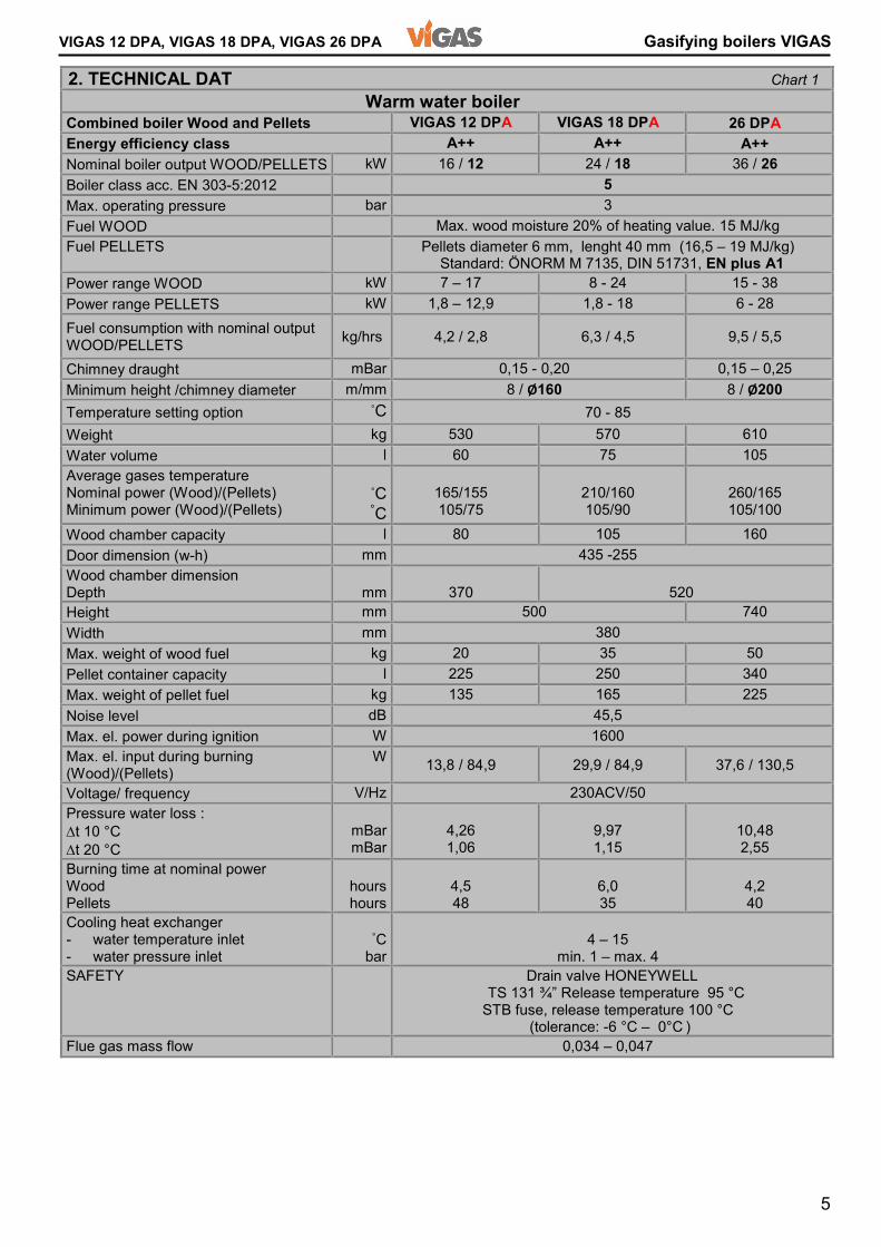
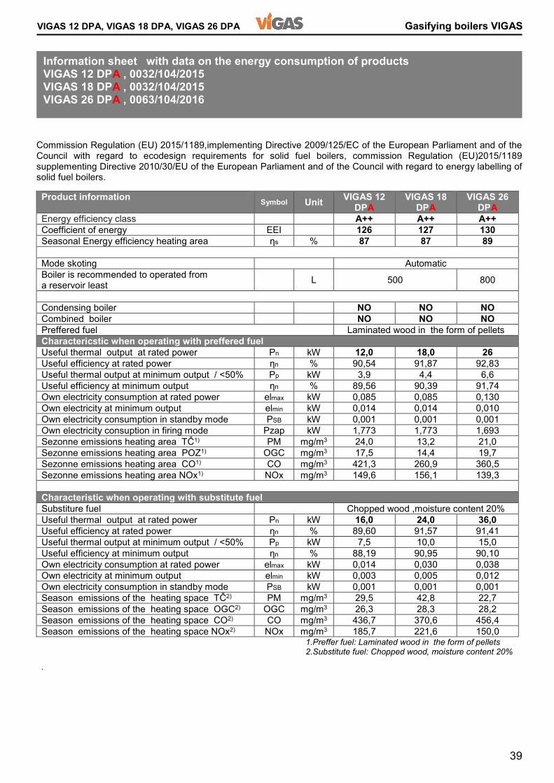
2. TECHNICAL DAT Chart 1 Warm water boiler Combined boiler Wood and Pellets VIGAS 12 DPA VIGAS 18 DPA 26 DPA Energy efficiency class A++ A++ A++ Nominal boiler output WOOD/PELLETS kW 16 / 12 24 / 18 36 / 26 Boiler class acc. EN 303-5:2012 5 Max. operating pressure bar 3 Fuel WOOD Max. wood moisture 20% of heating value. 15 MJ/kg Fuel PELLETS Pellets diameter 6 mm, lenght 40 mm (16,5 – 19 MJ/kg) Standard: ÖNORM M 7135, DIN 51731, EN plus A1 Power range WOOD kW 7 – 17 8 - 24 15 - 38 Power range PELLETS kW 1,8 – 12,9 1,8 - 18 6 - 28 Fuel consumption with nominal output WOOD/PELLETS kg/hrs 4,2 / 2,8 6,3 / 4,5 9,5 / 5,5 Chimney draught mBar 0,15 - 0,20 0,15 – 0,25 Minimum height /chimney diameter m/mm 8 / Ø160 8 / Ø200 Temperature setting option °C 70 - 85 Weight kg 530 570 610 Water volume l 60 75 105 Average gases temperature Nominal power (Wood)/(Pellets) Minimum power (Wood)/(Pellets) °C °C 165/155 105/75 210/160 105/90 260/165 105/100 Wood chamber capacity l 80 105 160 Door dimension (w-h) mm 435 -255 Wood chamber dimension Depth mm 370 520 Height mm 500 740 Width mm 380 Max. weight of wood fuel kg 20 35 50 Pellet container capacity l 225 250 340 Max. weight of pellet fuel kg 135 165 225 Noise level dB 45,5 Max. el. power during ignition W 1600 Max. el. input during burning (Wood)/(Pellets) W 13,8 / 84,9 29,9 / 84,9 37,6 / 130,5 Voltage/ frequency V/Hz 230ACV/50 Pressure water loss : ∆t 10 °C ∆t 20 °C mBar mBar 4,26 1,06 9,97 1,15 10,48 2,55 Burning time at nominal power Wood Pellets hours hours 4,5 48 6,0 35 4,2 40 Cooling heat exchanger - water temperature inlet - water pressure inlet °C bar 4 – 15 min. 1 – max. 4 SAFETY Drain valve HONEYWELL TS 131 ¾” Release temperature 95 °C STB fuse, release temperature 100 °C (tolerance: -6 °C – 0°C ) Flue gas mass flow 0,034 – 0,047
6
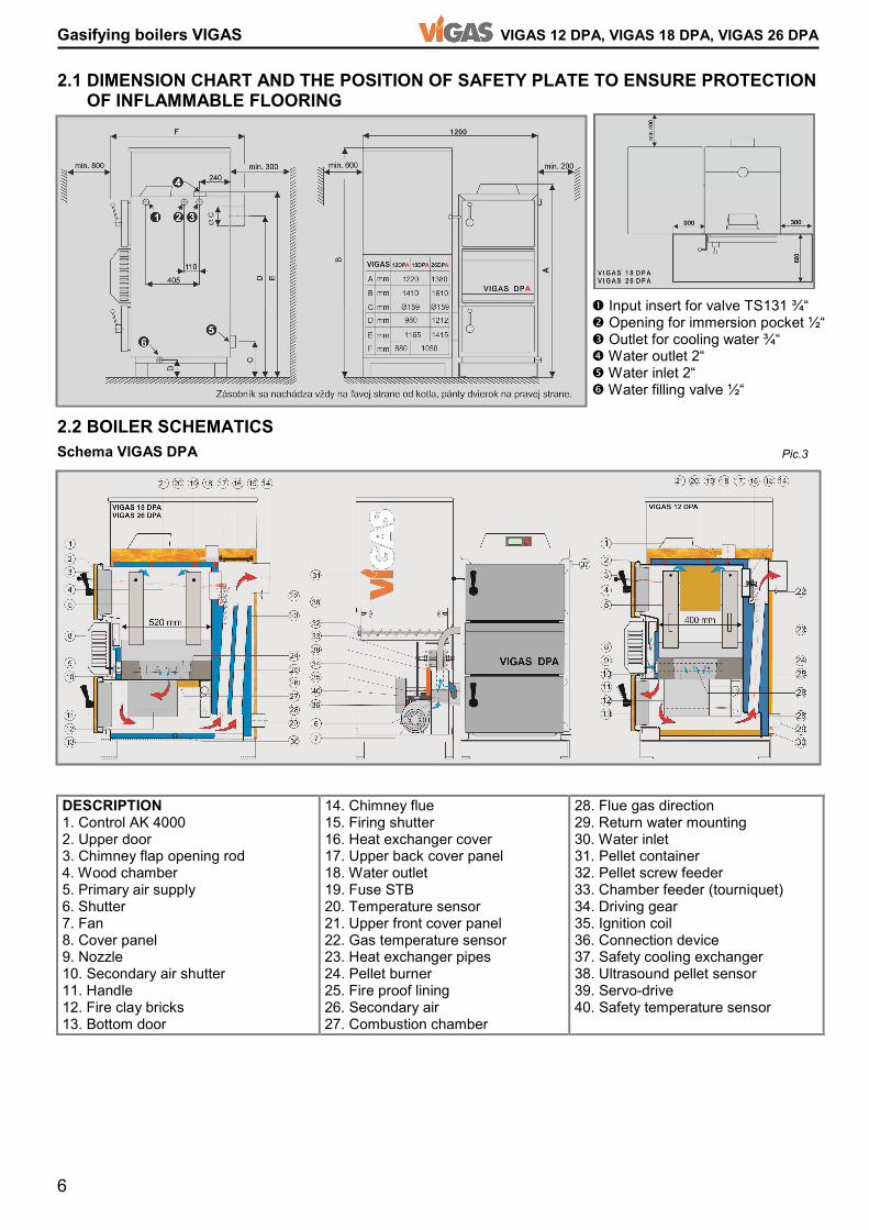
Gasifying boilers VIGAS VIGAS 12 DPA, VIGAS 18 DPA, VIGAS 26 DPA 2.1 DIMENSION CHART AND THE POSITION OF SAFETY PLATE TO ENSURE PROTECTION OF INFLAMMABLE FLOORING 2.2 BOILER SCHEMATICS DESCRIPTION 1. Control AK 4000 2. Upper door 3. Chimney flap opening rod 4. Wood chamber 5. Primary air supply 6. Shutter 7. Fan 8. Cover panel 9. Nozzle 10. Secondary air shutter 11. Handle 12. Fire clay bricks 13. Bottom door 14. Chimney flue 15. Firing shutter 16. Heat exchanger cover 17. Upper back cover panel 18. Water outlet 19. Fuse STB 20. Temperature sensor 21. Upper front cover panel 22. Gas temperature sensor 23. Heat exchanger pipes 24. Pellet burner 25. Fire proof lining 26. Secondary air 27. Combustion chamber 28. Flue gas direction 29. Return water mounting 30. Water inlet 31. Pellet container 32. Pellet screw feeder 33. Chamber feeder (tourniquet) 34. Driving gear 35. Ignition coil 36. Connection device 37. Safety cooling exchanger 38. Ultrasound pellet sensor 39. Servo-drive 40. Safety temperature sensor
Schema VIGAS DPA Pic.3 � Input insert for valve TS131 ¾“ � Opening for immersion pocket ½“ � Outlet for cooling water ¾“ � Water outlet 2“ � Water inlet 2“ � Water filling valve ½“

7
VIGAS 12 DPA, VIGAS 18 DPA, VIGAS 26 DPA Gasifying boilers VIGAS 3. DESCRIPTION OF AK 4000 CONTROL 3.1 Safety instructions 3.2 Connection to power supply 3.3 Operating conditions 3.4 Maintenance of AK 4000 control 3.5 Control panel Electronic control panel is equipped with buttons, display including symbols. Further information is available in the following chapters of the manual. The button options have combined functions, it depends on provided text and individual boiler configuration setting. Pic.6 1. Graphic display 128 x 64 pixels 2. Button ◄ with functions, ENTER 3. Button ▲ with functions, 4. Button ► with functions, EXIT menu (ESC) , 5. Button (ENTER) with functions, 6. LED light (green OK, red ERROR), 7. Button with functions. 1. Real time image. 2. Information line - current boiler figures shown Change ▲ or �. 3. Information about discharge fan and gas sensor . 4. Information about nominal power, when boiler is off. Pic.7Graphic information Line information (chap.10.5) 5. Graphic information about hydraulic schema 6. Boiler status information. 7. Pellet feeder information. 8. Symbols 9. Set figures 10. Currrent figures
Control AK 4000 presents integral part of VIGAS boilers. The control will be connected when power cord is plugged into a 220/230V power supply.The display is active when power cord is plugged-in (Pic.4). � Before you plug-in the power cord, please check all protective cover panels. � Avoid any contact of power cord with hot parts of the boiler (e.g. gas flue) � Make sure that upper insulation under the cover panel remains dry (risk of short circuit if damp) � Do not use any violent tow on the power cord. � Always disconnect the power cord, when new electrical devices are being installed to the boiler (e.g. room thermostat, discharge fan, circulation pump). � Do not remove protective cover panels, in particular the fan cover, when boiler in servise. � Check, whether voltage on the label is the same as your distribution network. � Always follow safety operation manual. Control AK 4000 is designed for operation with area temperature between +5 and +45 °C. The control cannot be used in moist environment or in direct sunlight. Keep in clean and dust free environment. Anti-static cloth or wet wipes are recommended to remove dust or impurities from metal cover or control panel.
Pic.4
8
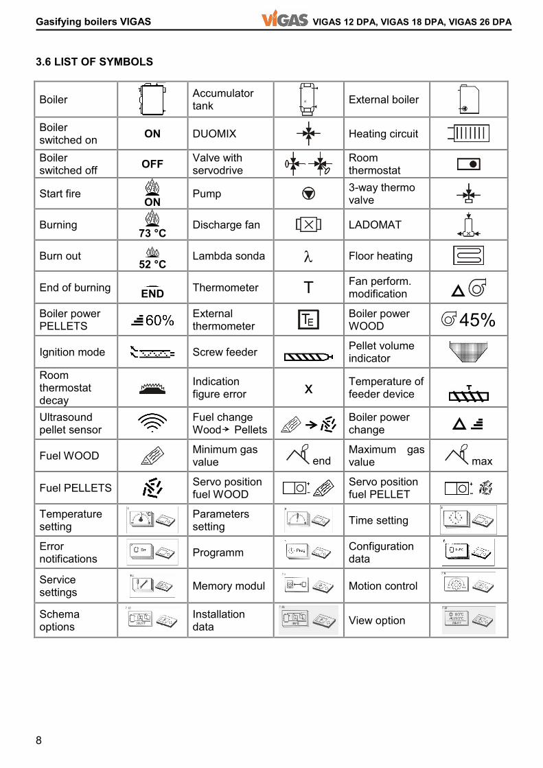
Gasifying boilers VIGAS VIGAS 12 DPA, VIGAS 18 DPA, VIGAS 26 DPA 3.6 LIST OF SYMBOLS Boiler Accumulator tank External boiler Boiler switched on ON DUOMIX Heating circuit Boiler switched off OFF Valve with servodrive Room thermostat Start fire ON Pump 3-way thermo valve Burning 73 °C Discharge fan LADOMAT Burn out 52 °C Lambda sonda λ Floor heating End of burning END Thermometer T Fan perform. modification Boiler power PELLETS External thermometer Boiler power WOOD 45% Ignition mode Screw feeder Pellet volume indicator Room thermostat decay Indication figure error x Temperature of feeder device Ultrasound pellet sensor Fuel change Wood Pellets Boiler power change Fuel WOOD Minimum gas value end Maximum gas value max Fuel PELLETS Servo position fuel WOOD Servo position fuel PELLET Temperature setting Parameters setting Time setting Error notifications Programm Configuration data Service settings Memory modul Motion control Schema options Installation data View option

9
VIGAS 12 DPA, VIGAS 18 DPA, VIGAS 26 DPA Gasifying boilers VIGASBoiler VIGAS 18 DPA offeres possibility, that during fuel change from pellets to wood or wood to pellets, it is not necessary to perform any technical modifications on the boiler body. It is only required to choose type of fuel on the display of AK 4000 control. After selecting the fuel type, servomotor driven shutter will automatically move to desired position (pic.3/6). Boiler design and air control enables automatic transition of fuel from „WOOD“ to „PELLETS“, after „WOOD“ fuel has burned out. 4. Boiler VIGAS DPA fuel PELLET Quick choice selection of fuel type using round button 4.1 VIGAS boiler control using fuel - PELLETS 4.1.1 Switch on the boiler 4.1.2 Boiler switched on – pellet ignition mode Symbol „OFF“ will appear, as shown on the picture, if boiler is switched off, by pressing middle button „ENTER“, round button pictogram appears. Ignition mode shows symbol „ON“. It is automatic process supported by chimney temperature monitoring. Discription of ignition: 1. Pump on, monitoring of current chimney gas temperature. 2. Ignition coil on ,fan will blow onto grate. 3. Screw feeder on . 4. Finishing ignition mode and switch to burning mode will start, when current gas temperature exceeds sensored gas temperature over 2,5°C. The boiler will switch off, if this condition is not realized, indicated by symbol „END“ and pellets ignition error. Ingniton pellets error: - Clean the burner (pic.3/24) too much ash on the burner, - Check pellet volume in the container, - Check igniton coil function (pic.3/35).
Fuel „PELLETS“ Fuel „WOOD“ Using button � select fuel pellets „ “ or fuel wood „ “. In case, discharge fan is used, see (chap.10.1.3) shown as this button +60 will switch on discharge fan for 60 seconds. It is used, for example during boiler clean up, it will minimize dust infiltration in the boiler room area. By pressing middle button „ENTER“ boiler gets into automatic pellet ignition.

10
Gasifying boilers VIGAS VIGAS 12 DPA, VIGAS 18 DPA, VIGAS 26 DPA 4.1.3 Boiler switched on – burning mode 4.1.4 Boiler shutdown (automatic) 4.1.5 Boiler shutdown (manually) 4.2 Parametres setting for fuel - PELLETS
Mode of combustion, the boiler will get after successful ignition of the pellets. Status is displayed by changing the "ON" → "520C". The burning mode, the boiler is controlled by a "PID controller based on the temperature of the boiler and flue temperatures. If the boiler temperature exceeds the desired temperature by 1°C, output is 0% if the temperature drops below 3°C desired temperature, the boiler is re-ignited. Current output is displayed in percentage as a symbol. "20%". Inside boiler container is placed ultrasound sensor, which detects pellet level. If pellets are above sensor level (container is full), this condition is displayed by symbol „ “. If pellets are below sensor level (container is half-empty), this condition is displayed by symbol „ “. Simultaneously, information line shows remaining time period for boiler to shutdown. This condition is displayed by empty container symbol “ “ and sign „END“. Pressing „ENTER“ display offers round button. Pressing button ⊳ boiler will shut down. After shutdown, the blowing fan is switched on. During 60s period pellet burner is being cooled down. By pressing � round button will disappear. To change setting press „ENTER“ for 2 seconds, in any boiler mode, by pressing button ▲. Parametres setting depends on type of the boiler and its configuration. By pressing buttons ▲� choose parameter to be changed and pressing „ENTER“ figure starts flashing.Using ▲� buttons select required figure and repeatedly press „ENTER“. 2sec.
11
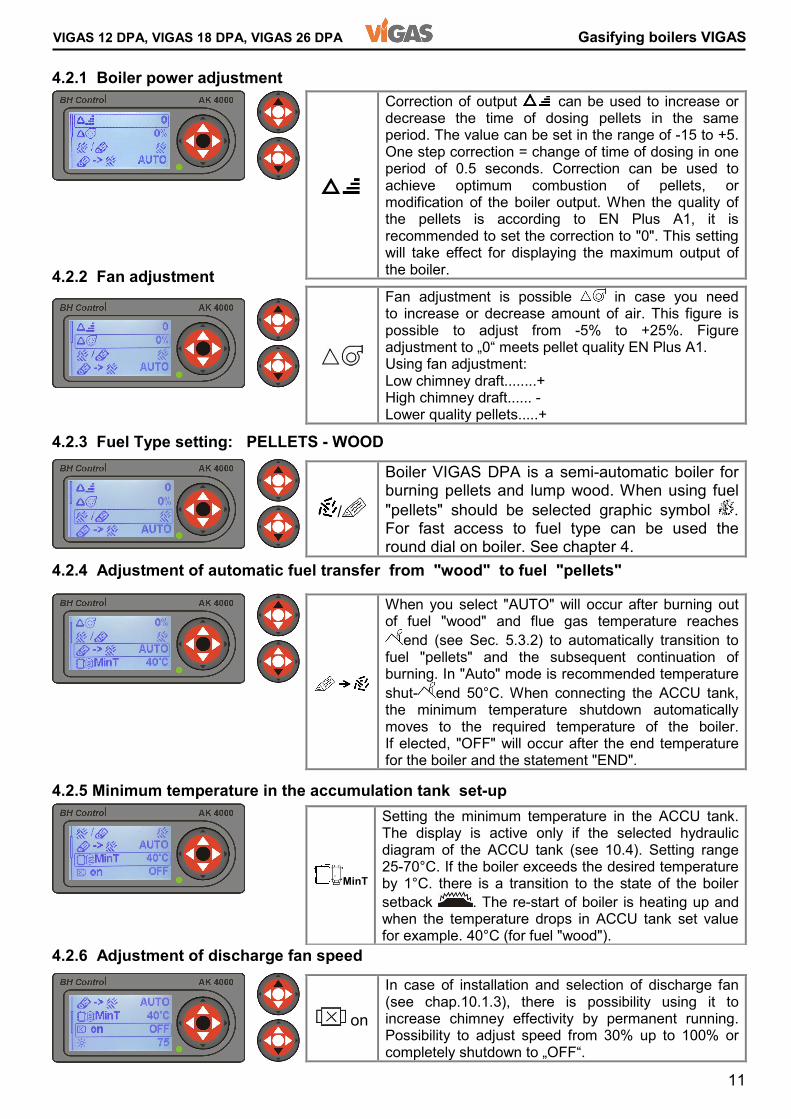
VIGAS 12 DPA, VIGAS 18 DPA, VIGAS 26 DPA Gasifying boilers VIGAS Fan adjustment is possible in case you need to increase or decrease amount of air. This figure is possible to adjust from -5% to +25%. Figure adjustment to „0“ meets pellet quality EN Plus A1. Using fan adjustment: Low chimney draft........+ High chimney draft...... - Lower quality pellets.....+
MinT Setting the minimum temperature in the ACCU tank. The display is active only if the selected hydraulic diagram of the ACCU tank (see 10.4). Setting range 25-70°C. If the boiler exceeds the desired temperature by 1°C. there is a transition to the state of the boiler setback . The re-start of boiler is heating up and when the temperature drops in ACCU tank set value for example. 40°C (for fuel "wood").
4.2.1 Boiler power adjustment 4.2.2 Fan adjustment 4.2.3 Fuel Type setting: PELLETS - WOOD 4.2.4 Adjustment of automatic fuel transfer from "wood" to fuel "pellets" 4.2.5 Minimum temperature in the accumulation tank set-up 4.2.6 Adjustment of discharge fan speed on In case of installation and selection of discharge fan (see chap.10.1.3), there is possibility using it to increase chimney effectivity by permanent running. Possibility to adjust speed from 30% up to 100% or completely shutdown to „OFF“.
Correction of output can be used to increase or decrease the time of dosing pellets in the same period. The value can be set in the range of -15 to +5. One step correction = change of time of dosing in one period of 0.5 seconds. Correction can be used to achieve optimum combustion of pellets, or modification of the boiler output. When the quality of the pellets is according to EN Plus A1, it is recommended to set the correction to "0". This setting will take effect for displaying the maximum output of the boiler. When you select "AUTO" will occur after burning out of fuel "wood" and flue gas temperature reaches end (see Sec. 5.3.2) to automatically transition to fuel "pellets" and the subsequent continuation of burning. In "Auto" mode is recommended temperature shut- end 50°C. When connecting the ACCU tank, the minimum temperature shutdown automatically moves to the required temperature of the boiler. If elected, "OFF" will occur after the end temperature for the boiler and the statement "END".
/ Boiler VIGAS DPA is a semi-automatic boiler for burning pellets and lump wood. When using fuel "pellets" should be selected graphic symbol . For fast access to fuel type can be used the round dial on boiler. See chapter 4.
12
Gasifying boilers VIGAS VIGAS 12 DPA, VIGAS 18 DPA, VIGAS 26 DPA 4.2.7 Display brightness adjustment 4.2.8 Display contrast adjustment 4.2.9 Adjustment of scrolling information line 5. BOILER VIGAS DPA fuel WOOD Quick choice selection of fuel type using round button 5.1 Boiler control VIGAS without discharge fan 5.1.1 Boiler switch on
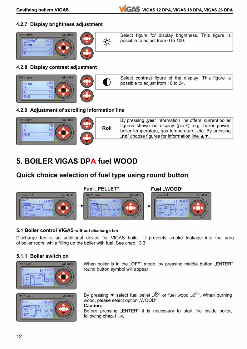
Select figure for display brightness. This figure is possible to adjust from 0 to 100. Select contrast figure of the display. This figure is possible to adjust from 16 to 24. Roll By pressing „yes“ information line offers current boiler figures shown on display (pic.7), e.g. boiler power, boiler temperature, gas temperature, etc. By pressing „no“ choose figures for information line ▲�. When boiler is in the „OFF“ mode, by pressing middle button „ENTER“ round button symbol will appear. Discharge fan is an additional device for VIGAS boiler. It prevents smoke leakage into the area of boiler room, while filling up the boiler with fuel. See chap.13.3. Fuel „PELLET“ Fuel „WOOD“ By pressing � select fuel pellet „ “ or fuel wood „ “. When burning wood, please select option „WOOD“ Caution: Before pressing „ENTER“ it is necessary to start fire inside boiler, following chap.11.4.
13
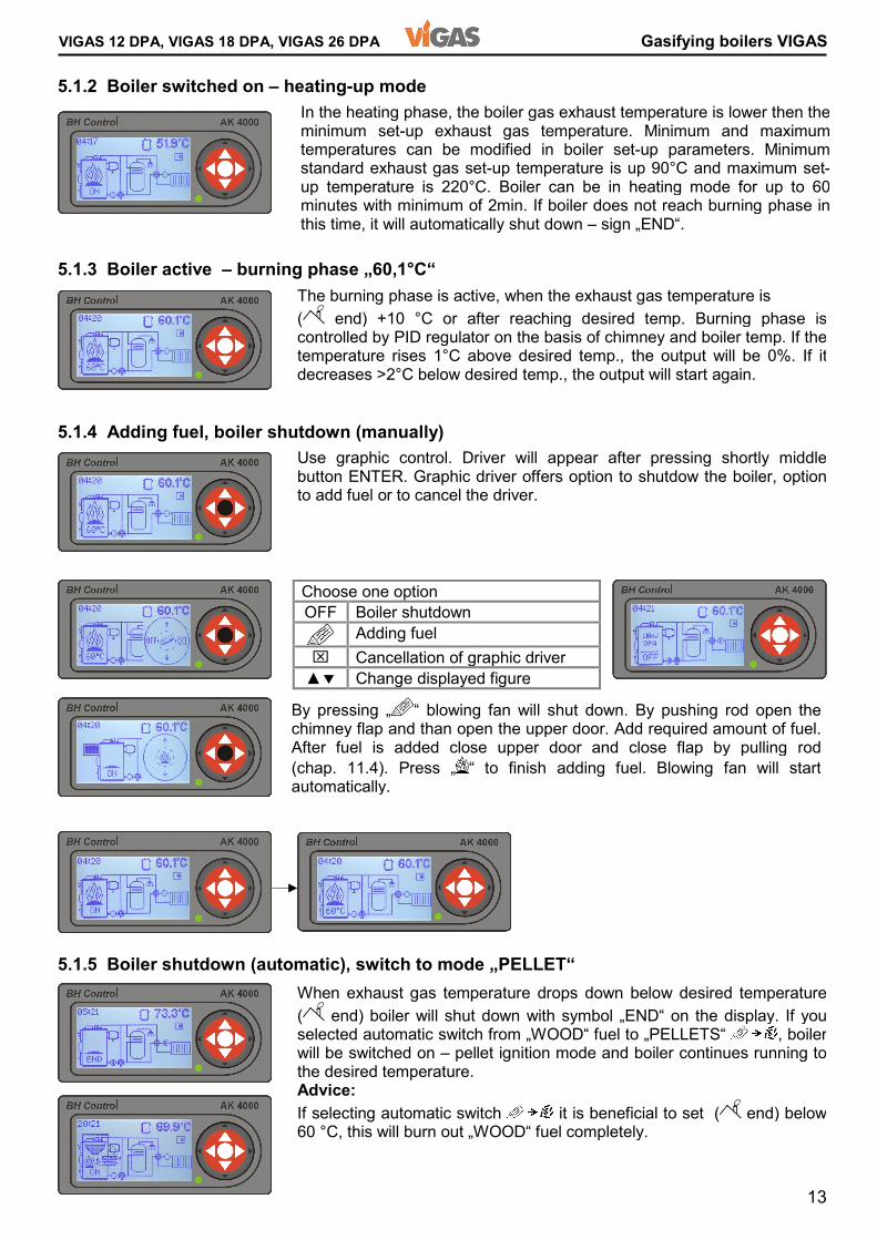
VIGAS 12 DPA, VIGAS 18 DPA, VIGAS 26 DPA Gasifying boilers VIGAS 5.1.2 Boiler switched on – heating-up mode 5.1.3 Boiler active – burning phase „60,1°C“ 5.1.4 Adding fuel, boiler shutdown (manually) 5.1.5 Boiler shutdown (automatic), switch to mode „PELLET“ By pressing „ “ blowing fan will shut down. By pushing rod open the chimney flap and than open the upper door. Add required amount of fuel.After fuel is added close upper door and close flap by pulling rod(chap. 11.4). Press „ “ to finish adding fuel. Blowing fan will start automatically.
In the heating phase, the boiler gas exhaust temperature is lower then the minimum set-up exhaust gas temperature. Minimum and maximum temperatures can be modified in boiler set-up parameters. Minimum standard exhaust gas set-up temperature is up 90°C and maximum set-up temperature is 220°C. Boiler can be in heating mode for up to 60 minutes with minimum of 2min. If boiler does not reach burning phase in this time, it will automatically shut down – sign „END“.
When exhaust gas temperature drops down below desired temperature( end) boiler will shut down with symbol „END“ on the display. If you selected automatic switch from „WOOD“ fuel to „PELLETS“ , boiler will be switched on – pellet ignition mode and boiler continues running to the desired temperature. Advice: If selecting automatic switch it is beneficial to set ( end) below60 °C, this will burn out „WOOD“ fuel completely.
The burning phase is active, when the exhaust gas temperature is ( end) +10 °C or after reaching desired temp. Burning phase is controlled by PID regulator on the basis of chimney and boiler temp. If the temperature rises 1°C above desired temp., the output will be 0%. If it decreases >2°C below desired temp., the output will start again. Choose one option OFF Boiler shutdown Adding fuel ⌧ Cancellation of graphic driver ▲� Change displayed figure Use graphic control. Driver will appear after pressing shortly middle button ENTER. Graphic driver offers option to shutdow the boiler, option to add fuel or to cancel the driver.
14
Gasifying boilers VIGAS VIGAS 12 DPA, VIGAS 18 DPA, VIGAS 26 DPA Choose one option +60 To start discharge fan for 60 s (used during heating-up) ON Switch on
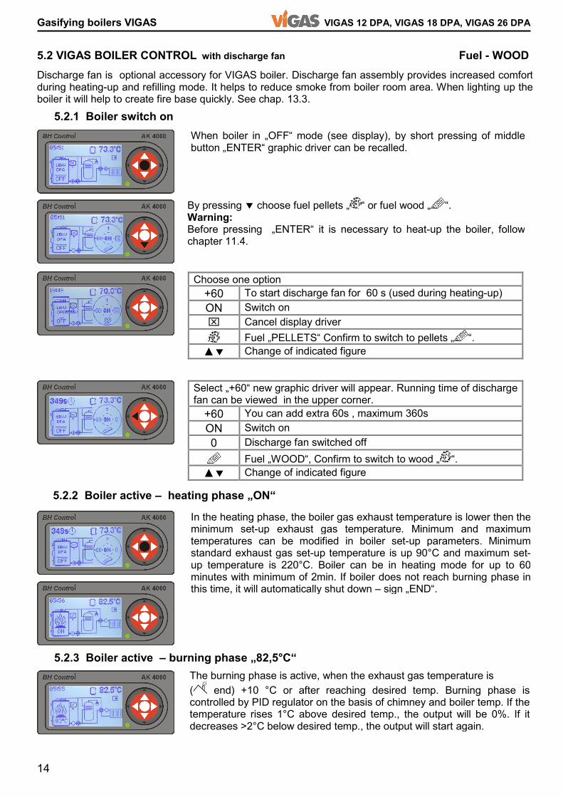
⌧ Cancel display driver Fuel „PELLETS“ Confirm to switch to pellets „ “. ▲� Change of indicated figure Select „+60“ new graphic driver will appear. Running time of discharge fan can be viewed in the upper corner. +60 You can add extra 60s , maximum 360s ON Switch on 0 Discharge fan switched off Fuel „WOOD“, Confirm to switch to wood „ “. ▲� Change of indicated figure 5.2 VIGAS BOILER CONTROL with discharge fan Fuel - WOOD 5.2.1 Boiler switch on 5.2.2 Boiler active – heating phase „ON“ 5.2.3 Boiler active – burning phase „82,5°C“
Discharge fan is optional accessory for VIGAS boiler. Discharge fan assembly provides increased comfort during heating-up and refilling mode. It helps to reduce smoke from boiler room area. When lighting up the boiler it will help to create fire base quickly. See chap. 13.3. When boiler in „OFF“ mode (see display), by short pressing of middle button „ENTER“ graphic driver can be recalled. In the heating phase, the boiler gas exhaust temperature is lower then the minimum set-up exhaust gas temperature. Minimum and maximum temperatures can be modified in boiler set-up parameters. Minimum standard exhaust gas set-up temperature is up 90°C and maximum set-up temperature is 220°C. Boiler can be in heating mode for up to 60 minutes with minimum of 2min. If boiler does not reach burning phase in this time, it will automatically shut down – sign „END“. The burning phase is active, when the exhaust gas temperature is ( end) +10 °C or after reaching desired temp. Burning phase is controlled by PID regulator on the basis of chimney and boiler temp. If the temperature rises 1°C above desired temp., the output will be 0%. If it decreases >2°C below desired temp., the output will start again.
By pressing � choose fuel pellets „ “ or fuel wood „ “. Warning: Before pressing „ENTER“ it is necessary to heat-up the boiler, follow chapter 11.4.
15
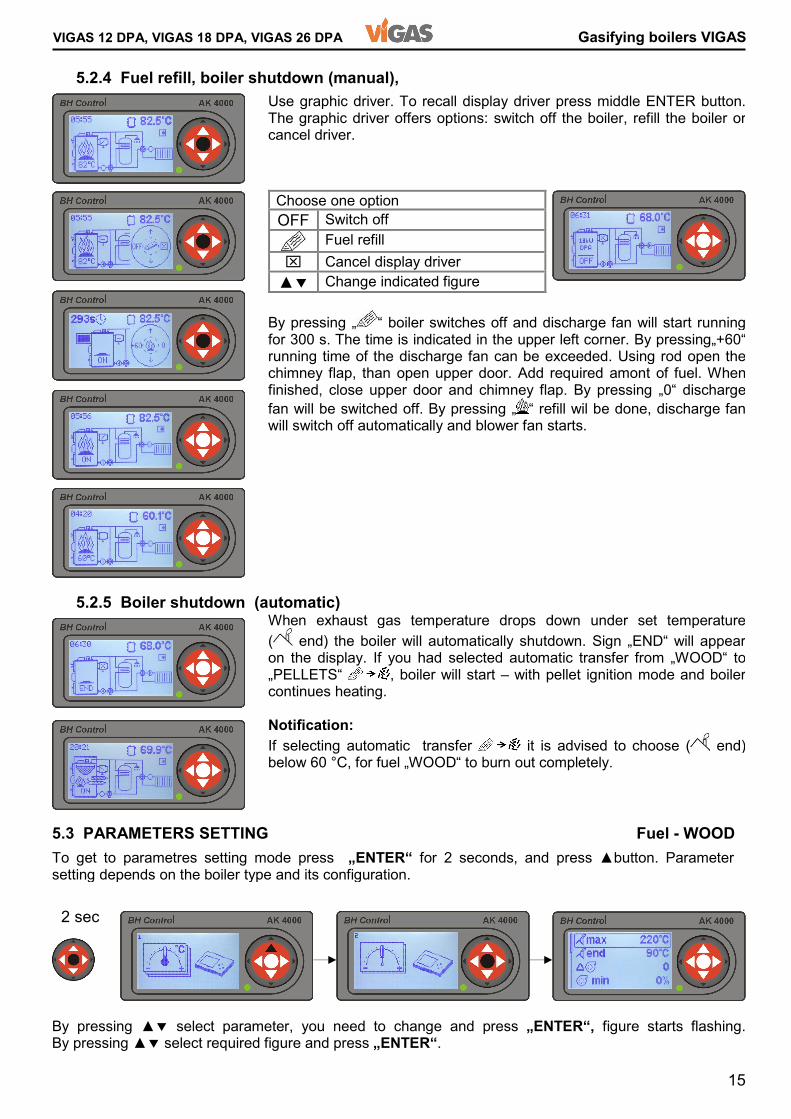
VIGAS 12 DPA, VIGAS 18 DPA, VIGAS 26 DPA Gasifying boilers VIGAS 5.2.4 Fuel refill, boiler shutdown (manual), 5.2.5 Boiler shutdown (automatic) 5.3 PARAMETERS SETTING Fuel - WOOD
Choose one option OFF Switch off Fuel refill ⌧ Cancel display driver ▲� Change indicated figure By pressing „ “ boiler switches off and discharge fan will start running for 300 s. The time is indicated in the upper left corner. By pressing„+60“ running time of the discharge fan can be exceeded. Using rod open the chimney flap, than open upper door. Add required amont of fuel. When finished, close upper door and chimney flap. By pressing „0“ discharge fan will be switched off. By pressing „ “ refill wil be done, discharge fan will switch off automatically and blower fan starts. When exhaust gas temperature drops down under set temperature( end) the boiler will automatically shutdown. Sign „END“ will appear on the display. If you had selected automatic transfer from „WOOD“ to „PELLETS“ , boiler will start – with pellet ignition mode and boiler continues heating. Notification: If selecting automatic transfer it is advised to choose ( end) below 60 °C, for fuel „WOOD“ to burn out completely.
Use graphic driver. To recall display driver press middle ENTER button.The graphic driver offers options: switch off the boiler, refill the boiler or cancel driver.
To get to parametres setting mode press „ENTER“ for 2 seconds, and press ▲button. Parameter setting depends on the boiler type and its configuration. By pressing ▲� select parameter, you need to change and press „ENTER“, figure starts flashing.By pressing ▲� select required figure and press „ENTER“. 2 sec
16
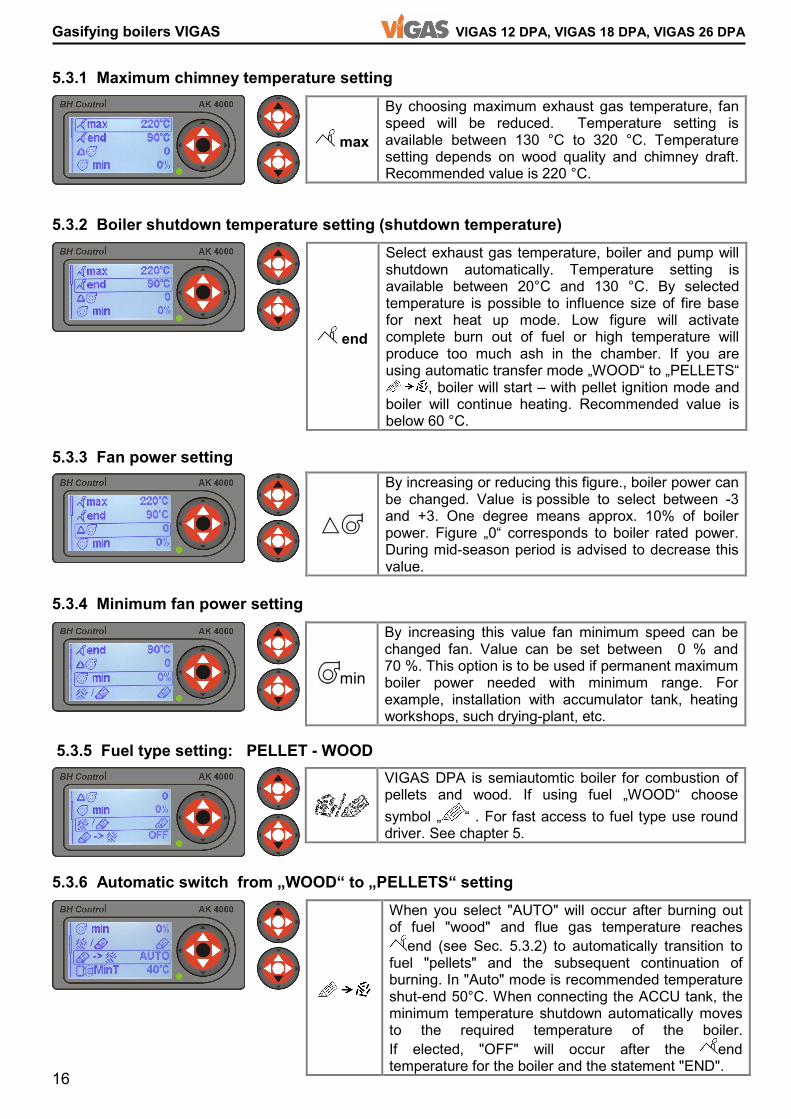
Gasifying boilers VIGAS VIGAS 12 DPA, VIGAS 18 DPA, VIGAS 26 DPA max By choosing maximum exhaust gas temperature, fan speed will be reduced. Temperature setting is available between 130 °C to 320 °C. Temperature setting depends on wood quality and chimney draft. Recommended value is 220 °C. By increasing or reducing this figure., boiler power can be changed. Value is possible to select between -3 and +3. One degree means approx. 10% of boiler power. Figure „0“ corresponds to boiler rated power. During mid-season period is advised to decrease this value. min By increasing this value fan minimum speed can be changed fan. Value can be set between 0 % and 70 %. This option is to be used if permanent maximum boiler power needed with minimum range. For example, installation with accumulator tank, heating workshops, such drying-plant, etc.
5.3.1 Maximum chimney temperature setting 5.3.2 Boiler shutdown temperature setting (shutdown temperature) 5.3.3 Fan power setting 5.3.4 Minimum fan power setting 5.3.5 Fuel type setting: PELLET - WOOD 5.3.6 Automatic switch from „WOOD“ to „PELLETS“ setting VIGAS DPA is semiautomtic boiler for combustion of pellets and wood. If using fuel „WOOD“ choose symbol „ “ . For fast access to fuel type use round driver. See chapter 5.
end Select exhaust gas temperature, boiler and pump will shutdown automatically. Temperature setting is available between 20°C and 130 °C. By selected temperature is possible to influence size of fire base for next heat up mode. Low figure will activate complete burn out of fuel or high temperature will produce too much ash in the chamber. If you are using automatic transfer mode „WOOD“ to „PELLETS“ , boiler will start – with pellet ignition mode and boiler will continue heating. Recommended value is below 60 °C. When you select "AUTO" will occur after burning out of fuel "wood" and flue gas temperature reaches end (see Sec. 5.3.2) to automatically transition to fuel "pellets" and the subsequent continuation of burning. In "Auto" mode is recommended temperature shut-end 50°C. When connecting the ACCU tank, the minimum temperature shutdown automatically moves to the required temperature of the boiler. If elected, "OFF" will occur after the end temperature for the boiler and the statement "END".
17
VIGAS 12 DPA, VIGAS 18 DPA, VIGAS 26 DPA Gasifying boilers VIGAS
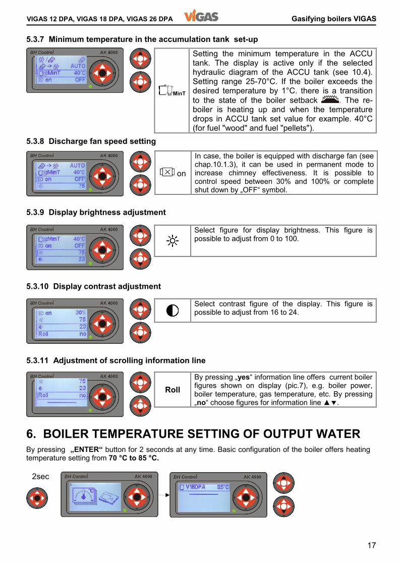
By pressing „ENTER“ button for 2 seconds at any time. Basic configuration of the boiler offers heating temperature setting from 70 °C to 85 °C.
5.3.7 Minimum temperature in the accumulation tank set-up 5.3.8 Discharge fan speed setting 5.3.9 Display brightness adjustment 5.3.10 Display contrast adjustment 5.3.11 Adjustment of scrolling information line 6. BOILER TEMPERATURE SETTING OF OUTPUT WATER on In case, the boiler is equipped with discharge fan (see chap.10.1.3), it can be used in permanent mode to increase chimney effectiveness. It is possible to control speed between 30% and 100% or complete shut down by „OFF“ symbol. MinT Setting the minimum temperature in the ACCU tank. The display is active only if the selected hydraulic diagram of the ACCU tank (see 10.4). Setting range 25-70°C. If the boiler exceeds the desired temperature by 1°C. there is a transition to the state of the boiler setback . The re-boiler is heating up and when the temperature drops in ACCU tank set value for example. 40°C (for fuel "wood" and fuel "pellets"). Select figure for display brightness. This figure is possible to adjust from 0 to 100. Select contrast figure of the display. This figure is possible to adjust from 16 to 24. Roll By pressing „yes“ information line offers current boiler figures shown on display (pic.7), e.g. boiler power, boiler temperature, gas temperature, etc. By pressing „no“ choose figures for information line ▲�. 2sec
18
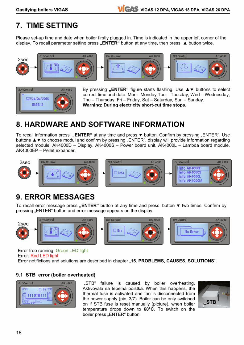
Gasifying boilers VIGAS VIGAS 12 DPA, VIGAS 18 DPA, VIGAS 26 DPA 7. TIME SETTING 8. HARDWARE AND SOFTWARE INFORMATION 9. ERROR MESSAGES 9.1 STB error (boiler overheated) By pressing „ENTER“ figure starts flashing. Use ▲� buttons to select correct time and date. Mon - Monday,Tue – Tuesday, Wed – Wednesday, Thu – Thursday, Fri – Friday, Sat – Saturday, Sun – Sunday. Warning: During electricity short-cut time stops. To recall information press „ENTER“ at any time and press � button. Confirm by pressing „ENTER“. Use buttons ▲� to choose modul and confirm by pressing „ENTER“. display will provide information regarding selected module: AK4000D – Display, AK4000S – Power board unit, AK4000L – Lambda board module, AK4000EP – Pellet expander. To recall error message press „ENTER“ button at any time and press button � two times. Confirm by pressing „ENTER“ button and error message appears on the display.
Please set-up time and date when boiler firstly plugged in. Time is indicated in the upper left corner of the display. To recall parameter setting press „ENTER“ button at any time, then press ▲ button twice.
Error free running: Green LED light Error: Red LED light Error notifictions and solutions are described in chapter „15. PROBLEMS, CAUSES, SOLUTIONS“. „STB“ failure is caused by boiler overheating.Aktivovala sa tepelná poistka. When this happens, the thermal fuse is activated and fan is disconnected from the power supply (pic. 3/7). Boiler can be only switched on if STB fuse is reset manually (picture), when boiler temperature drops down to 60°C. To switch on the boiler press „ENTER“ button. STB
2sec 2sec 2sec

19
VIGAS 12 DPA, VIGAS 18 DPA, VIGAS 26 DPA Gasifying boilers VIGAS 10. SERVICE SETTINGS USING PASSWORD PIN 0000 10.1 SERVICE SETTINGS 10.1.1 Boiler type setting 10.1.2 Exhaust gas thermometer option 10.1.3 Discharge fan option 10.1.4 Boiler thermometer type setting
Using password PIN 0000 can be applied only in special cases. In servise settings you can select type of boiler, hydraulic schema, etc. Mode for servise setting „PIN 0000“ can be recalled by pressing „ENTER“button at any time, then press ▲ and hold ◄ for 4 s. „PIN 0000“ will appear. Press „ENTER“ button 4 times. Service setting symbol will appear on the display. Press „ENTER“ and select service operationusing ▲� buttons. Offers to choose boiler type.Type of the boiler must be identical with production label. Label: V18 – boiler power, TVZ – hotair boiler, UD – wood-coal, DP – wood,pellets, DPA – wood-pellets automatic, L – Lambda. When exhaust gas thermometer is damaged, it is possible to disconnect. It is possible to run boiler without thermometer. Water temperature will be used to shutdown the boiler. yes – boiler with thermometer, no – boiler without thermometer Discharge fan is an optional accessory of the boiler. Aftre connection to the boiler and control unit AK4000 it is necessary to select option „yes“. yes – boiler with discharge fan no – boiler without discharge fan
By pressing „ENTER“ service settings can be recalled. Using buttons ▲� choose parameter, by pressing „ENTER“ figure starts flashing. WARNING Display unit AK 4000 is used to operate all type of VIGAS boilers. It isimportant, that software setting is identical with boiler type. When boiler is „OFF“ display unit shows type of the boiler compliant with boiler nominal power (pic.7/4). For proper boiler operation, type of the boiler must be always identical with production label. Always check if AK4000 display unit is replaced!!! T Offers selecting two types of boiler thermometers: 1.Standard : Type KTY 2.Alternative : Type PT1000
2sec 4sec 4x
20
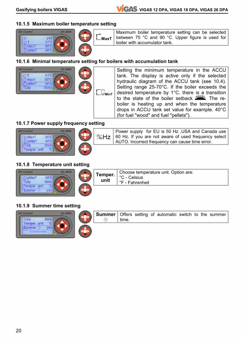
Gasifying boilers VIGAS VIGAS 12 DPA, VIGAS 18 DPA, VIGAS 26 DPA 10.1.5 Maximum boiler temperature setting 10.1.6 Minimal temperature setting for boilers with accumulation tank 10.1.7 Power supply frequency setting 10.1.8 Temperature unit setting 10.1.9 Summer time setting
MaxT Maximum boiler temperature setting can be selected between 75 °C and 90 °C. Upper figure is used for boiler with accumulator tank. Power supply for EU is 50 Hz ,USA and Canada use 60 Hz. If you are not aware of used frequency select AUTO. Incorrect frequency can cause time error. Temper. unit Choose temperature unit. Option are: °C - Celsius °F - Fahrenheit Summer
Offers setting of automatic switch to the summer time. MinT Setting the minimum temperature in the ACCU tank. The display is active only if the selected hydraulic diagram of the ACCU tank (see 10.4). Setting range 25-70°C. If the boiler exceeds the desired temperature by 1°C. there is a transition to the state of the boiler setback . The re-boiler is heating up and when the temperature drops in ACCU tank set value for example. 40°C (for fuel "wood" and fuel "pellets").
21
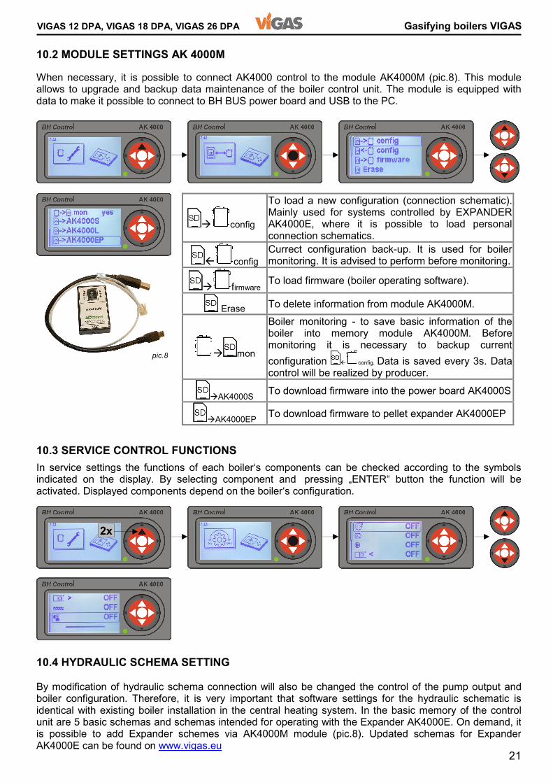
VIGAS 12 DPA, VIGAS 18 DPA, VIGAS 26 DPA Gasifying boilers VIGAS 10.2 MODULE SETTINGS AK 4000M 10.3 SERVICE CONTROL FUNCTIONS 10.4 HYDRAULIC SCHEMA SETTING By modification of hydraulic schema connection will also be changed the control of the pump output and boiler configuration. Therefore, it is very important that software settings for the hydraulic schematic is identical with existing boiler installation in the central heating system. In the basic memory of the control unit are 5 basic schemas and schemas intended for operating with the Expander AK4000E. On demand, it is possible to add Expander schemes via AK4000M module (pic.8). Updated schemas for Expander AK4000E can be found on www.vigas.eu
When necessary, it is possible to connect AK4000 control to the module AK4000M (pic.8). This module allows to upgrade and backup data maintenance of the boiler control unit. The module is equipped with data to make it possible to connect to BH BUS power board and USB to the PC. � config To load a new configuration (connection schematic). Mainly used for systems controlled by EXPANDER AK4000E, where it is possible to load personal connection schematics. config Currect configuration back-up. It is used for boiler monitoring. It is advised to perform before monitoring. � firmware To load firmware (boiler operating software). Erase To delete information from module AK4000M.
� mon Boiler monitoring - to save basic information of the boiler into memory module AK4000M. Before monitoring it is necessary to backup current configuration config. Data is saved every 3s. Data control will be realized by producer. �AK4000S To download firmware into the power board AK4000S �AK4000EP To download firmware to pellet expander AK4000EP In service settings the functions of each boiler‘s components can be checked according to the symbols indicated on the display. By selecting component and pressing „ENTER“ button the function will be activated. Displayed components depend on the boiler‘s configuration. 2x pic.8
22
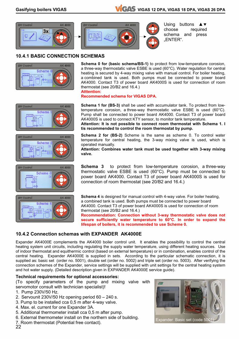
Gasifying boilers VIGAS VIGAS 12 DPA, VIGAS 18 DPA, VIGAS 26 DPA 10.4.1 BASIC CONNECTION SCHEMAS 10.4.2 Connection schemas with EXPANDER AK4000E Expander AK4000E complements the AK4000 boiler control unit. It enables the possibility to control the central heating system unit circuits, including regulating the supply water temperature, using different heating sources. Use of indoor thermostat and equithermic control (based on external temperature) or in combination, enables control of thecentral heating. Expander AK4000E is supplied in sets. According to the particular schematic connection, it is supplied as: basic set (order no. 5001), double set (order no. 5002) and triple set (order no. 5003). After verifying the connection schemes of the Expander, service settings will be supplied with unit settings for the central heating system and hot water supply. (Detailed description given in EXPANDER AK4000E service guide). Schema 4 is designed for manual control with 4-way valve. For boiler heating, a combined tank is used. Both pumps must be connected to power board AK4000. Contact T3 of power board AK4000S is used for connection of room thermostat (see 20/B2 and 16.4.) Recommendation: Connection without 3-way thermostatic valve does not secure sufficiently water temperature to 60°C. In order to expand the lifespan of boilers, it is recommended to use Scheme 0.
3x Using buttons ▲�choose required schema and press „ENTER“. Schema 1 for (BS-3) shall be used with accumulator tank. To protect from low-temperature corosion, a three-way thermostatic valve ESBE is used (60°C). Pump shall be connected to power board AK4000. Contact T3 of power board AK4000S is used to connect KTY sensor, to monitor tank temperature. Attention: It is not possible to connect room thermostat with Schema 1. I tis recommended to control the room thermostat by pump. Schema 2 for (BS-2) Scheme is the same as scheme 0. To control watertemperature for central heating, the 3-way mixing valve is used, which is operated manually. Attention: Combines water tank must be used together with 3-way mixing valve. Schema 3 to protect from low-temperature corosion, a three-way thermostatic valve ESBE is used (60°C). Pump must be connected to power board AK4000. Contact T3 of power board AK4000S is used for connection of room thermostat (see 20/B2 and 16.4.) Schema 0 for (basic schema/BS-1) to protect from low-temperature corosion, a three-way thermostatic valve ESBE is used (60°C). Water regulation for central heating is secured by 4-way mixing valve with manual control. For boiler heating, a combined tank is used. Both pumps must be connected to power board AK4000. Contact T3 of power board AK4000S is used for connection of room thermostat (see 20/B2 and 16.4.) Atttention: Recommended schema for VIGAS DPA.
Expander Basic set (code 5001) Technical requirements for optional accessories: (To specify parameters of the pump and mixing valve with servomotor consult with technician specialist)! 1. Pump 230V/50 Hz. 2. Servounit 230V/50 Hz opening period 60 – 240 s. 3. Pump to be installed cca 0,5 m after 4-way valve. 4. Max. el. current for one Expander 3A. 5. Additional thermometer install cca 0,5 m after pump. 6. External thermometer install on the northern side of building. 7. Room thermostat (Potential free contact).
23
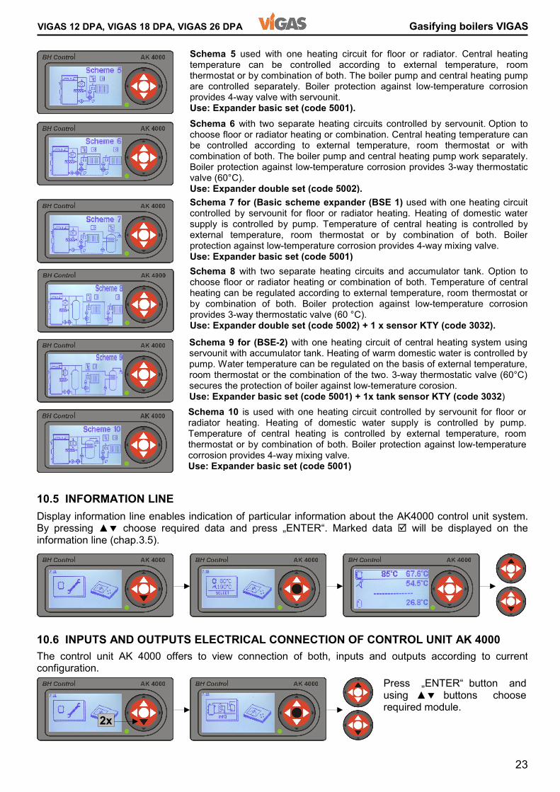
VIGAS 12 DPA, VIGAS 18 DPA, VIGAS 26 DPA Gasifying boilers VIGAS 10.5 INFORMATION LINE 10.6 INPUTS AND OUTPUTS ELECTRICAL CONNECTION OF CONTROL UNIT AK 4000 Schema 5 used with one heating circuit for floor or radiator. Central heating temperature can be controlled according to external temperature, room thermostat or by combination of both. The boiler pump and central heating pump are controlled separately. Boiler protection against low-temperature corrosion provides 4-way valve with servounit. Use: Expander basic set (code 5001). Schema 6 with two separate heating circuits controlled by servounit. Option to choose floor or radiator heating or combination. Central heating temperature can be controlled according to external temperature, room thermostat or with combination of both. The boiler pump and central heating pump work separately. Boiler protection against low-temperature corrosion provides 3-way thermostatic valve (60°C). Use: Expander double set (code 5002). Schema 7 for (Basic scheme expander (BSE 1) used with one heating circuit controlled by servounit for floor or radiator heating. Heating of domestic water supply is controlled by pump. Temperature of central heating is controlled by external temperature, room thermostat or by combination of both. Boiler protection against low-temperature corrosion provides 4-way mixing valve. Use: Expander basic set (code 5001) Schema 8 with two separate heating circuits and accumulator tank. Option to choose floor or radiator heating or combination of both. Temperature of central heating can be regulated according to external temperature, room thermostat or by combination of both. Boiler protection against low-temperature corrosion provides 3-way thermostatic valve (60 °C). Use: Expander double set (code 5002) + 1 x sensor KTY (code 3032).
Display information line enables indication of particular information about the AK4000 control unit system. By pressing ▲� choose required data and press „ENTER“. Marked data will be displayed on the information line (chap.3.5). The control unit AK 4000 offers to view connection of both, inputs and outputs according to current configuration. Press „ENTER“ button and using ▲� buttons choose required module. 2x Schema 10 is used with one heating circuit controlled by servounit for floor or radiator heating. Heating of domestic water supply is controlled by pump. Temperature of central heating is controlled by external temperature, room thermostat or by combination of both. Boiler protection against low-temperature corrosion provides 4-way mixing valve. Use: Expander basic set (code 5001) Schema 9 for (BSE-2) with one heating circuit of central heating system using servounit with accumulator tank. Heating of warm domestic water is controlled by pump. Water temperature can be regulated on the basis of external temperature, room thermostat or the combination of the two. 3-way thermostatic valve (60°C) secures the protection of boiler against low-temerature corosion. Use: Expander basic set (code 5001) + 1x tank sensor KTY (code 3032)
24
Gasifying boilers VIGAS VIGAS 12 DPA, VIGAS 18 DPA, VIGAS 26 DPA 11. OPERATING INSTRUCTIONS 11.1 Prior to the boiler operation carry out necessary actions ! 11.2 BOILER HEAT-UP fuel „PELLETS“
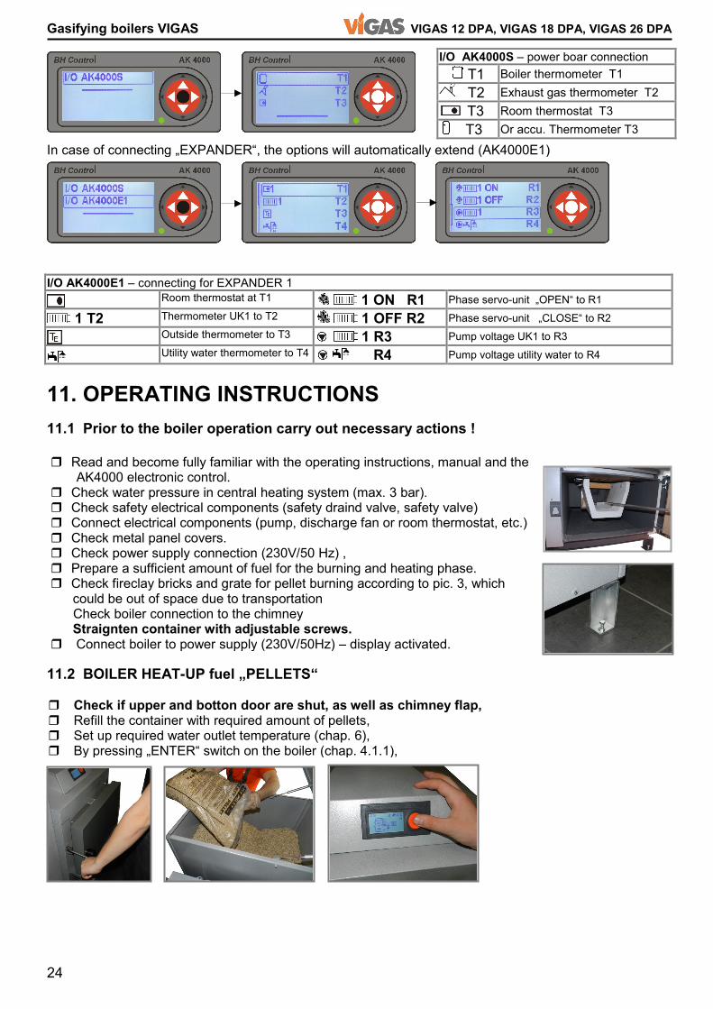
I/O AK4000S – power boar connection T1 Boiler thermometer T1 T2 Exhaust gas thermometer T2 T3 Room thermostat T3 T3 Or accu. Thermometer T3 I/O AK4000E1 – connecting for EXPANDER 1 Room thermostat at T1 1 ON R1 Phase servo-unit „OPEN“ to R1 1 T2 Thermometer UK1 to T2 1 OFF R2 Phase servo-unit „CLOSE“ to R2 Outside thermometer to T3 1 R3 Pump voltage UK1 to R3 Utility water thermometer to T4 R4 Pump voltage utility water to R4 In case of connecting „EXPANDER“, the options will automatically extend (AK4000E1) � Read and become fully familiar with the operating instructions, manual and the AK4000 electronic control. � Check water pressure in central heating system (max. 3 bar). � Check safety electrical components (safety draind valve, safety valve) � Connect electrical components (pump, discharge fan or room thermostat, etc.) � Check metal panel covers. � Check power supply connection (230V/50 Hz) , � Prepare a sufficient amount of fuel for the burning and heating phase. � Check fireclay bricks and grate for pellet burning according to pic. 3, which could be out of space due to transportation Check boiler connection to the chimney Straignten container with adjustable screws. � Connect boiler to power supply (230V/50Hz) – display activated. � Check if upper and botton door are shut, as well as chimney flap, � Refill the container with required amount of pellets, � Set up required water outlet temperature (chap. 6), � By pressing „ENTER“ switch on the boiler (chap. 4.1.1),
25
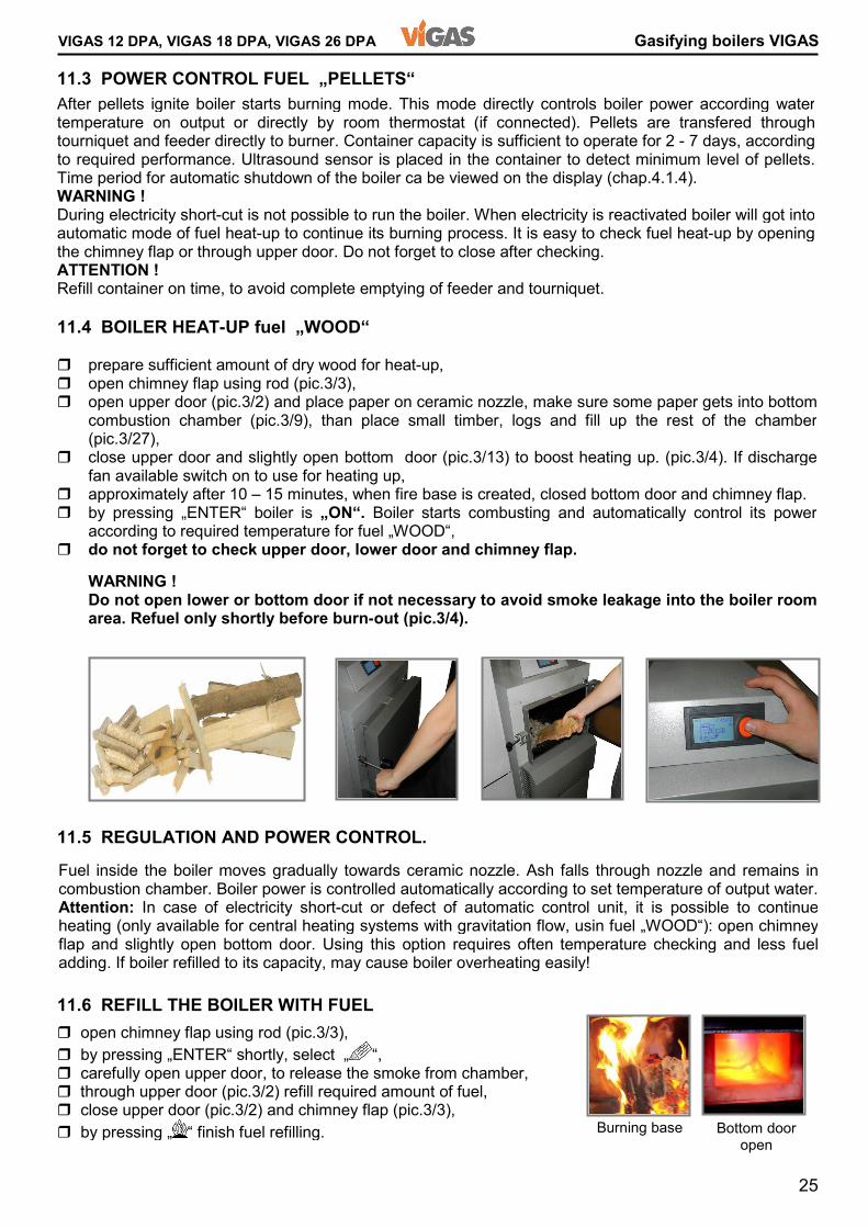
VIGAS 12 DPA, VIGAS 18 DPA, VIGAS 26 DPA Gasifying boilers VIGAS 11.3 POWER CONTROL FUEL „PELLETS“ 11.4 BOILER HEAT-UP fuel „WOOD“ 11.5 REGULATION AND POWER CONTROL. 11.6 REFILL THE BOILER WITH FUEL Fuel inside the boiler moves gradually towards ceramic nozzle. Ash falls through nozzle and remains in combustion chamber. Boiler power is controlled automatically according to set temperature of output water. Attention: In case of electricity short-cut or defect of automatic control unit, it is possible to continue heating (only available for central heating systems with gravitation flow, usin fuel „WOOD“): open chimney flap and slightly open bottom door. Using this option requires often temperature checking and less fuel adding. If boiler refilled to its capacity, may cause boiler overheating easily! � open chimney flap using rod (pic.3/3), � by pressing „ENTER“ shortly, select „ “, � carefully open upper door, to release the smoke from chamber, � through upper door (pic.3/2) refill required amount of fuel, � close upper door (pic.3/2) and chimney flap (pic.3/3), � by pressing „ “ finish fuel refilling.
After pellets ignite boiler starts burning mode. This mode directly controls boiler power according water temperature on output or directly by room thermostat (if connected). Pellets are transfered through tourniquet and feeder directly to burner. Container capacity is sufficient to operate for 2 - 7 days, according to required performance. Ultrasound sensor is placed in the container to detect minimum level of pellets.Time period for automatic shutdown of the boiler ca be viewed on the display (chap.4.1.4). WARNING ! During electricity short-cut is not possible to run the boiler. When electricity is reactivated boiler will got into automatic mode of fuel heat-up to continue its burning process. It is easy to check fuel heat-up by opening the chimney flap or through upper door. Do not forget to close after checking. ATTENTION ! Refill container on time, to avoid complete emptying of feeder and tourniquet. � prepare sufficient amount of dry wood for heat-up, � open chimney flap using rod (pic.3/3), � open upper door (pic.3/2) and place paper on ceramic nozzle, make sure some paper gets into bottom combustion chamber (pic.3/9), than place small timber, logs and fill up the rest of the chamber (pic.3/27), � close upper door and slightly open bottom door (pic.3/13) to boost heating up. (pic.3/4). If discharge fan available switch on to use for heating up, � approximately after 10 – 15 minutes, when fire base is created, closed bottom door and chimney flap. � by pressing „ENTER“ boiler is „ON“. Boiler starts combusting and automatically control its power according to required temperature for fuel „WOOD“, � do not forget to check upper door, lower door and chimney flap. WARNING ! Do not open lower or bottom door if not necessary to avoid smoke leakage into the boiler room area. Refuel only shortly before burn-out (pic.3/4).
Burning base Bottom door open

26
Gasifying boilers VIGAS VIGAS 12 DPA, VIGAS 18 DPA, VIGAS 26 DPA 11.7 BOILER CLEANING
Wood characteristic table Wood Fuel efficiency [MJ/kg] 20% humidity Fuel efficiency [MJ/kg] 25% humidity Hardness * weight [kg/m3] 25% humidity Poplar 12,9 12,3 1 530 Fir 15,9 14,0 1 575 Spurce 15,3 13,1 1 575 Willow 16,9 12,8 1 665 Pine 18,4 13,6 1 680 Alder 16,7 12,9 2 640 Birch 15 13,5 2 780 Maple 15 13,6 4 660 Beech 15,5 12,5 4 865 Ashen 15,7 12,7 4 865 Locust 16,3 12,7 4 930 Oak 15,9 13,2 4,5 840 [kg/m3] = [kg/fm], fm – fullmeter, * (1 very soft...5 very hard) Important information !!! � Use only recommended fuel. � Do not overload the boiler with fuel during mid-season period, to avoid tar production. � When refilling the boiler, make sure that fuel does not get between mounting and chimney flap. This would stop chimney flap from proper closing. � It is important to lay wood properly, to allow proper closing of the upper door. Forced closing can damage heatproof lining. � It is recommended that only person over 18 years, should operate the boiler.
� Gasification chamber cleaning It is necessary to remove tar from the gasification chamber once a week. It is recommended to burn it off with the upper door and chimney flap open. If there is extra ash which did not fall through the nozzle(pic. 3/9) into the fireclay combustion chamber, this should be removed from time to time. Fuel bunker will increase to the original size and primary air flow through nozzle will be enhanced. Optimal wood burning and keeping minimum temperature of the reverse water at 60°C will ensure that the gasifying chamber and exchanger will only soot little. Using damp wood may cause water to condense on the walls of the combustion chamber, which creates tar on the surface. � Exchanger cleaning It is necessary to clean exchanger pipes once a month using the fire rake (round plate). Than remove ash from lower part of combustion chamber through bottom door. Recommendation: If the exchanger is not cleaned regularly it will become clogged with tar. Do not use solvents. The boiler must be cleaned whilst it is hot! Heat boiler to approx 80°C (without fan) through open upper door and chimney flap. Then close the flap and door. Using gloves, carefully open exchanger cover. Clean clogged pipes with relevant accessories. After cleaning, close exchanger cover and let the boiler burn / gasify for approx. 5 hours at maximum performance, in order to get rid of any remaining tar. Avoid this situation in the future. WARNING: Boiler room area must be permanetly ventilated at maximum during cleaning time. � Combustion chamber cleaning It is recommended to sweep out ash and dust that has fallen and settled in the combustion chamber once every 3-5 days. When using pellets, clean the pellet burner once a month. NOTICE ! Pellet burner is placed together with firebricks inside combustion chamber. Please take care for burner to be cleaned and placed to its initial space.
Humidity dependence period( wood cuts) Fir SPURCE Beech Recommended humidity 20% OAK 12141618202224262830
6 12 18 24Number of months after cuttinghumidity [%] Combustion chamber Burner
27
VIGAS 12 DPA, VIGAS 18 DPA, VIGAS 26 DPA Gasifying boilers VIGAS 12. BOILER MAINTENANCE AND REPAIRS 12.1 DOOR TIGHTNESS 12.2 CHIMNEY FLAP TIGHTNESS 12.3 CERAMIC NOZZLE
The contractor provides regular service and boiler maintenance. During operation it is necessary to check water pressure, door seal, chimney flap tightness, exchanger cover seal, flue cleanliness and fan performance. Warning! When boiler switched off at the end of heating season clean properly combustion chamber. To avoid residual humidity leave the bottom door open tohether with chimney flap. Do not leave pellets inside container and feeder to avoid wetting and desintegration. Door is stabilized by 3 points – 2 rotary pins and door shutter. If the door is tightless, there is possibility to set by shutter or hinge side. Slightly turn hinge to release and turn hinge screw and then move door in desired direction. Number„1“ is area where gasket is joined. The heatproof nozzle is a block made of heat-proof concrete and its use is to to mix gases with secondary air to ensure efficient burning. The nozzle is located on the water cooling rack. The nozzle is surrounded with heat-proof concrete at the same height as the nozzle. The life of the nozzle is dependent on mechanical damage as a result of fuel loading or stoking the fire. Therefore, the nozzle is considered as a spare part. Cracks noticed on the nozzle are not a reason to change the nozzle. It is only necessary to change the nozzle if it is dropped or is broken. Remove the pieces of the broken nozzle and replace with a new nozzle ensuring that it is inserted and fits into the opening. When cleaning exchanger pipes (pic.3/23) make sure that flap area is clean, as well as flap itself (pic.3/15). Flap leakage can decrease boiler power. Notification: Flap is secured by 2 bolts with loose fitting. Do not fasten!!! �
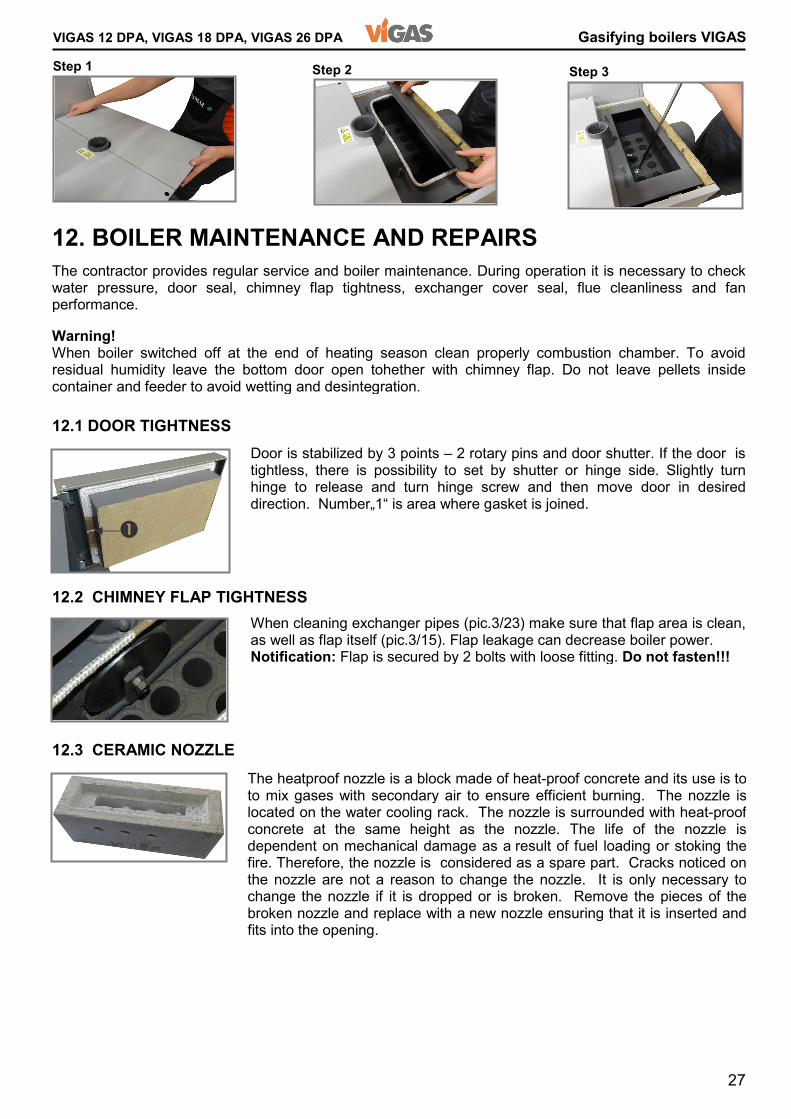
Step 1 Step 2 Step 3
28
Gasifying boilers VIGAS VIGAS 12 DPA, VIGAS 18 DPA, VIGAS 26 DPA 12.4 SECONDARY AIR FLAPS SETTING 12.5 PELLET BURNER 12.6 TOURNIQUET AND PELLET FEEDER 12.7 AIR DISTRIBUTOR, FAN, SERVO-UNIT 12.8 CHIMNEY EXHAUST GAS THERMOMETER
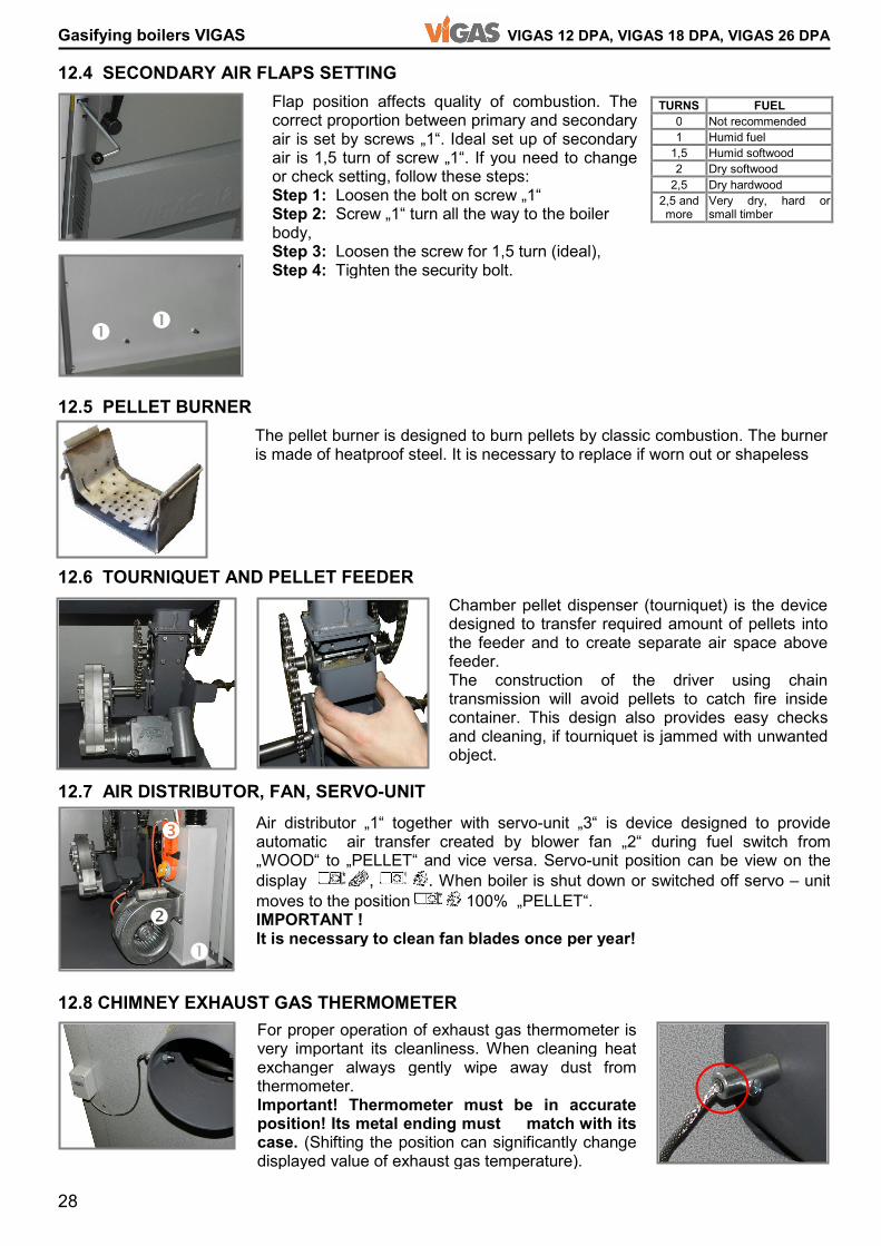
TURNS FUEL 0 Not recommended 1 Humid fuel 1,5 Humid softwood 2 Dry softwood 2,5 Dry hardwood 2,5 and more Very dry, hard or small timber Flap position affects quality of combustion. The correct proportion between primary and secondary air is set by screws „1“. Ideal set up of secondary air is 1,5 turn of screw „1“. If you need to change or check setting, follow these steps: Step 1: Loosen the bolt on screw „1“ Step 2: Screw „1“ turn all the way to the boiler body, Step 3: Loosen the screw for 1,5 turn (ideal), Step 4: Tighten the security bolt.
For proper operation of exhaust gas thermometer is very important its cleanliness. When cleaning heat exchanger always gently wipe away dust from thermometer. Important! Thermometer must be in accurate position! Its metal ending must match with its case. (Shifting the position can significantly change displayed value of exhaust gas temperature).
The pellet burner is designed to burn pellets by classic combustion. The burner is made of heatproof steel. It is necessary to replace if worn out or shapeless Chamber pellet dispenser (tourniquet) is the device designed to transfer required amount of pellets into the feeder and to create separate air space above feeder. The construction of the driver using chain transmission will avoid pellets to catch fire inside container. This design also provides easy checks and cleaning, if tourniquet is jammed with unwanted object. � �
� �
� Air distributor „1“ together with servo-unit „3“ is device designed to provide automatic air transfer created by blower fan „2“ during fuel switch from „WOOD“ to „PELLET“ and vice versa. Servo-unit position can be view on the display , . When boiler is shut down or switched off servo – unit moves to the position 100% „PELLET“. IMPORTANT ! It is necessary to clean fan blades once per year!
29
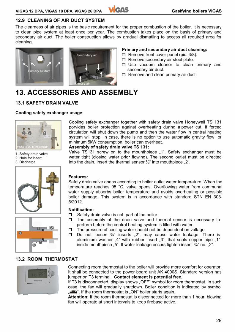
VIGAS 12 DPA, VIGAS 18 DPA, VIGAS 26 DPA Gasifying boilers VIGASPrimary and secondary air duct cleaning: � Remove front cover panel (pic. 3/8). � Remove secondary air steel plate. � Use vacuum cleaner to clean primary and secondary air duct. � Remove and clean primary air duct. 12.9 CLEANING OF AIR DUCT SYSTEM 13. ACCESSORIES AND ASSEMBLY 13.1 SAFETY DRAIN VALVE Cooling safety exchanger usage: 13.2 ROOM THERMOSTAT
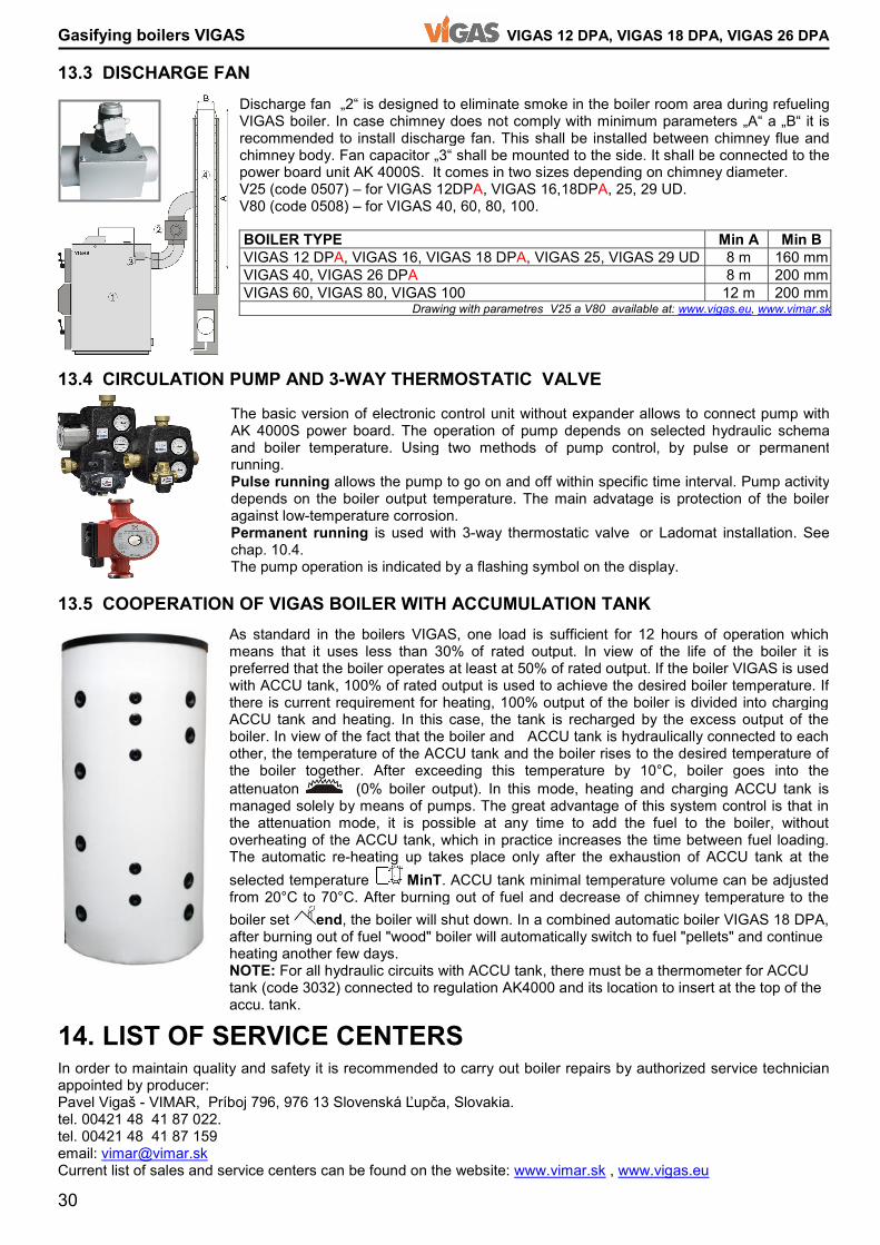
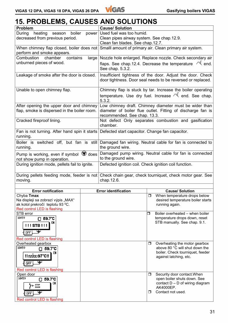
The clearness of air pipes is the basic requirement for the proper combustion of the boiler. It is necessary to clean pipe system at least once per year. The combustion takes place on the basis of primary and secondary air duct. The boiler construction allows by gradual dismatling to access all required area for cleaning. Cooling safety exchanger together with safety drain valve Honeywell TS 131 porvides boiler protection against overheating during a power cut. If forced circulation will shut down the pump and then the water flow in central heating system will stop. In case, there is no option to use automatic gravity flow or minimum 5kW consumption, boiler can overheat. Assembly of safety drain valve TS 131: Valve TS131 screw on to the mounthpiece „1“. Safety exchanger must be water tight (closing water prior flowing). The second outlet must be directed into the drain. Insert the thermal sensor ½“ into mouthpiece „2“. Notification: � Safety drain valve is not part of the boiler. � The assembly of the drain valve and thermal sensor is necessary to perform before the central heating system is filled with water. � The pressure of cooling water should not be dependent on voltage. � Do not loosen ¾“ inserts „2“, may cause water leakage. There is aluminium washer „4“ with rubber insert „3“, that seals copper pipe „1“ inside mouthpiece „5“. If water leakage occurs tighten insert ¾“ no. „2“. Features: Safety drain valve opens according to boiler outlet water temperature. When the temperature reaches 95 °C, valve opens. Overflowing water from communal water supply absorbs boiler temperature and avoids overheating or possible boiler damage. This system is in accordance with standard STN EN 303-5/2012. 1. Safety drain valve 2. Hole for insert 3. Discharge Connecting room thermostat to the boiler will provide more comfort for operator. It shall be connected to the power board unit AK 4000S. Standard version has jumper on T3 terminal. Contact element is potential free. If T3 is disconnected, display shows „OFF“ symbol for room thermostat. In such case, the fan will gradually shutdown. Boiler condition is indicated by symbol„ “. If the room thermostat is „ON“ boiler starts again. Attention: If the room thermostat is disconnected for more than 1 hour, blowing fan will operate at short intervals to keep firebase active.
Secondary air Primary air Primary air duct
30
Gasifying boilers VIGAS VIGAS 12 DPA, VIGAS 18 DPA, VIGAS 26 DPA 13.3 DISCHARGE FAN 13.4 CIRCULATION PUMP AND 3-WAY THERMOSTATIC VALVE 13.5 COOPERATION OF VIGAS BOILER WITH ACCUMULATION TANK 14. LIST OF SERVICE CENTERS In order to maintain quality and safety it is recommended to carry out boiler repairs by authorized service technician appointed by producer: Pavel Vigaš - VIMAR, Príboj 796, 976 13 Slovenská Ľupča, Slovakia. tel. 00421 48 41 87 022. tel. 00421 48 41 87 159 email: [email protected] Current list of sales and service centers can be found on the website: www.vimar.sk , www.vigas.eu
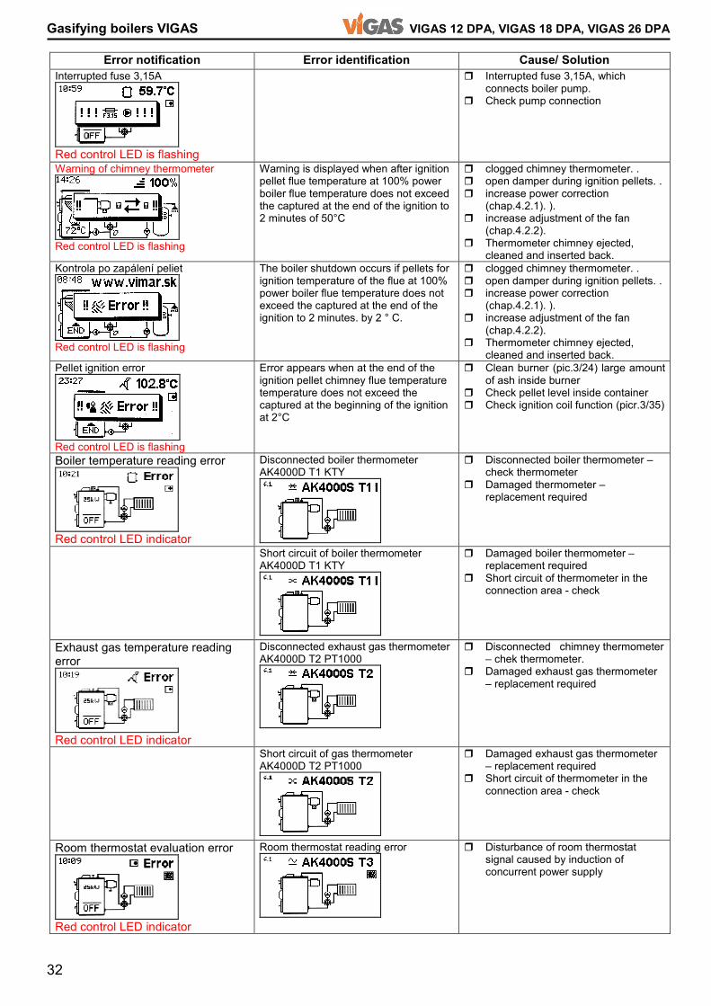
BOILER TYPE Min A Min B VIGAS 12 DPA, VIGAS 16, VIGAS 18 DPA, VIGAS 25, VIGAS 29 UD 8 m 160 mm VIGAS 40, VIGAS 26 DPA 8 m 200 mm VIGAS 60, VIGAS 80, VIGAS 100 12 m 200 mm Drawing with parametres V25 a V80 available at: www.vigas.eu, www.vimar.sk The basic version of electronic control unit without expander allows to connect pump with AK 4000S power board. The operation of pump depends on selected hydraulic schema and boiler temperature. Using two methods of pump control, by pulse or permanent running. Pulse running allows the pump to go on and off within specific time interval. Pump activity depends on the boiler output temperature. The main advatage is protection of the boiler against low-temperature corrosion. Permanent running is used with 3-way thermostatic valve or Ladomat installation. See chap. 10.4. The pump operation is indicated by a flashing symbol on the display. Discharge fan „2“ is designed to eliminate smoke in the boiler room area during refueling VIGAS boiler. In case chimney does not comply with minimum parameters „A“ a „B“ it is recommended to install discharge fan. This shall be installed between chimney flue and chimney body. Fan capacitor „3“ shall be mounted to the side. It shall be connected to the power board unit AK 4000S. It comes in two sizes depending on chimney diameter. V25 (code 0507) – for VIGAS 12DPA, VIGAS 16,18DPA, 25, 29 UD. V80 (code 0508) – for VIGAS 40, 60, 80, 100.
As standard in the boilers VIGAS, one load is sufficient for 12 hours of operation which means that it uses less than 30% of rated output. In view of the life of the boiler it is preferred that the boiler operates at least at 50% of rated output. If the boiler VIGAS is used with ACCU tank, 100% of rated output is used to achieve the desired boiler temperature. If there is current requirement for heating, 100% output of the boiler is divided into charging ACCU tank and heating. In this case, the tank is recharged by the excess output of the boiler. In view of the fact that the boiler and ACCU tank is hydraulically connected to each other, the temperature of the ACCU tank and the boiler rises to the desired temperature of the boiler together. After exceeding this temperature by 10°C, boiler goes into the attenuaton (0% boiler output). In this mode, heating and charging ACCU tank is managed solely by means of pumps. The great advantage of this system control is that in the attenuation mode, it is possible at any time to add the fuel to the boiler, without overheating of the ACCU tank, which in practice increases the time between fuel loading. The automatic re-heating up takes place only after the exhaustion of ACCU tank at the selected temperature MinT. ACCU tank minimal temperature volume can be adjusted from 20°C to 70°C. After burning out of fuel and decrease of chimney temperature to the boiler set end, the boiler will shut down. In a combined automatic boiler VIGAS 18 DPA, after burning out of fuel "wood" boiler will automatically switch to fuel "pellets" and continue heating another few days. NOTE: For all hydraulic circuits with ACCU tank, there must be a thermometer for ACCU tank (code 3032) connected to regulation AK4000 and its location to insert at the top of the accu. tank.
31
VIGAS 12 DPA, VIGAS 18 DPA, VIGAS 26 DPA Gasifying boilers VIGAS 15. PROBLEMS, CAUSES AND SOLUTIONS Problem Cause/ Solution During heating season boiler power decreased from previous period. Used fuel was too humid. Clean pipes airway system. See chap.12.9. Clean fan blades. See chap.12.7. When chimney flap closed, boiler does not perform and smoke appears. Smalll amount of primary air. Clean primary air system. Combustion chamber contains large unburned pieces of wood. Nozzle hole enlarged. Replace nozzle. Check secondary air flaps. See chap.12.4. Decrease the temperature end. See chap. 5.3.2. Leakage of smoke after the door is closed. Insufficient tightness of the door. Adjust the door. Check door tightness. Door seal needs to be reversed or replaced. Unable to open chimney flap. Chimney flap is stuck by tar. Increase the boiler operating temperature. Use dry fuel. Increase end. See chap. 5.3.2. After opening the upper door and chimney flap, smoke is dispersed in the boiler room. Low chimney draft. Chimney diameter must be wider than diameter of boiler flue outlet. Fitting of discharge fan is recommended. See chap. 13.3. Cracked fireproof lining. Not defect Only separates combustion and gasification chamber. Fan is not turning. After hand spin it starts running. Defected start capacitor. Change fan capacitor. Boiler is switched off, but fan is still running. Damaged fan wiring. Neutral cable for fan is connected to the ground wire. Pump is working, even if symbol does not show pump in operation. Damaged pump wiring. Neutral cable for fan is connected to the ground wire. During ignition mode, pellets fail to ignite. Defected ignition coil. Check ignition coil function. During pellets feeding mode, feeder is not moving. Check chain gear, check tourniquet, check motor gear. See chap.12.6. Error notification Error identification Cause/ Solution Chyba Tmax Na displeji sa zobrazí výpis „MAX“ ak kotol prekročí teplotu 93 0C. Red control LED is flashing � When temperature drops below desired temperature boiler starts running again. STB error Red control LED is flashing � Boiler overheated – when boiler temperature drops down, reset STB manually. See chap. 9.1. Overheated gearbox Red control LED is flashing � Overheating the motor gearbox above 80 °C will shut down the boiler. Check tourniquet, feeder against latching, etc. Open door Red control LED is flashing � Security door contact.When open boiler shuts down. See contact D – D of wiring diagram AK4000EP. � Contact not used.
32
Gasifying boilers VIGAS VIGAS 12 DPA, VIGAS 18 DPA, VIGAS 26 DPA
Error notification Error identification Cause/ Solution Interrupted fuse 3,15A Red control LED is flashing � Interrupted fuse 3,15A, which connects boiler pump. � Check pump connection Warning of chimney thermometer Red control LED is flashing Warning is displayed when after ignition pellet flue temperature at 100% power boiler flue temperature does not exceed the captured at the end of the ignition to 2 minutes of 50°C � clogged chimney thermometer. . � open damper during ignition pellets. . � increase power correction (chap.4.2.1). ). � increase adjustment of the fan (chap.4.2.2). � Thermometer chimney ejected, cleaned and inserted back. Kontrola po zapálení peliet Red control LED is flashing The boiler shutdown occurs if pellets for ignition temperature of the flue at 100% power boiler flue temperature does not exceed the captured at the end of the ignition to 2 minutes. by 2 ° C. � clogged chimney thermometer. . � open damper during ignition pellets. . � increase power correction (chap.4.2.1). ). � increase adjustment of the fan (chap.4.2.2). � Thermometer chimney ejected, cleaned and inserted back. Pellet ignition error Red control LED is flashing Error appears when at the end of the ignition pellet chimney flue temperature temperature does not exceed the captured at the beginning of the ignition at 2°C � Clean burner (pic.3/24) large amount of ash inside burner � Check pellet level inside container � Check ignition coil function (picr.3/35) Boiler temperature reading error Red control LED indicator Disconnected boiler thermometer AK4000D T1 KTY � Disconnected boiler thermometer – check thermometer � Damaged thermometer – replacement required Short circuit of boiler thermometer AK4000D T1 KTY � Damaged boiler thermometer – replacement required � Short circuit of thermometer in the connection area - check Exhaust gas temperature reading error Red control LED indicator Disconnected exhaust gas thermometer AK4000D T2 PT1000 � Disconnected chimney thermometer – chek thermometer. � Damaged exhaust gas thermometer – replacement required Short circuit of gas thermometer AK4000D T2 PT1000 � Damaged exhaust gas thermometer – replacement required � Short circuit of thermometer in the connection area - check Room thermostat evaluation error Red control LED indicator Room thermostat reading error � Disturbance of room thermostat signal caused by induction of concurrent power supply
33
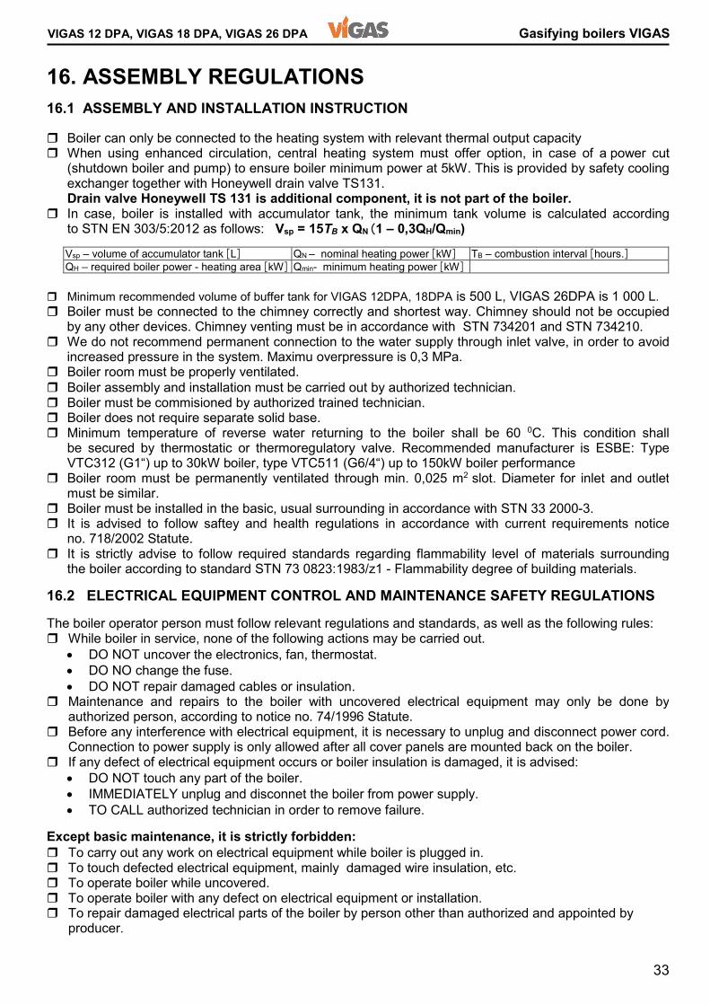
VIGAS 12 DPA, VIGAS 18 DPA, VIGAS 26 DPA Gasifying boilers VIGAS 16. ASSEMBLY REGULATIONS 16.1 ASSEMBLY AND INSTALLATION INSTRUCTION 16.2 ELECTRICAL EQUIPMENT CONTROL AND MAINTENANCE SAFETY REGULATIONS � Boiler assembly and installation must be carried out by authorized technician. � Boiler must be commisioned by authorized trained technician. � Boiler does not require separate solid base. � Minimum temperature of reverse water returning to the boiler shall be 60 0C. This condition shall be secured by thermostatic or thermoregulatory valve. Recommended manufacturer is ESBE: Type VTC312 (G1“) up to 30kW boiler, type VTC511 (G6/4“) up to 150kW boiler performance � Boiler room must be permanently ventilated through min. 0,025 m2 slot. Diameter for inlet and outlet must be similar. � Boiler must be installed in the basic, usual surrounding in accordance with STN 33 2000-3. � It is advised to follow saftey and health regulations in accordance with current requirements noticeno. 718/2002 Statute. � It is strictly advise to follow required standards regarding flammability level of materials surrounding the boiler according to standard STN 73 0823:1983/z1 - Flammability degree of building materials. The boiler operator person must follow relevant regulations and standards, as well as the following rules: � While boiler in service, none of the following actions may be carried out.
• DO NOT uncover the electronics, fan, thermostat. • DO NO change the fuse. • DO NOT repair damaged cables or insulation.
� Maintenance and repairs to the boiler with uncovered electrical equipment may only be done by authorized person, according to notice no. 74/1996 Statute. � Before any interference with electrical equipment, it is necessary to unplug and disconnect power cord. Connection to power supply is only allowed after all cover panels are mounted back on the boiler. � If any defect of electrical equipment occurs or boiler insulation is damaged, it is advised:
• DO NOT touch any part of the boiler. • IMMEDIATELY unplug and disconnet the boiler from power supply. • TO CALL authorized technician in order to remove failure.
� Boiler can only be connected to the heating system with relevant thermal output capacity � When using enhanced circulation, central heating system must offer option, in case of a power cut (shutdown boiler and pump) to ensure boiler minimum power at 5kW. This is provided by safety cooling exchanger together with Honeywell drain valve TS131. Drain valve Honeywell TS 131 is additional component, it is not part of the boiler. � In case, boiler is installed with accumulator tank, the minimum tank volume is calculated according to STN EN 303/5:2012 as follows: Vsp = 15TB x QN (1 – 0,3QH/Qmin) Vsp – volume of accumulator tank [L] QN – nominal heating power [kW] TB – combustion interval [hours.] QH – required boiler power - heating area [kW] Qmin- minimum heating power [kW] � Minimum recommended volume of buffer tank for VIGAS 12DPA, 18DPA is 500 L, VIGAS 26DPA is 1 000 L. � Boiler must be connected to the chimney correctly and shortest way. Chimney should not be occupied by any other devices. Chimney venting must be in accordance with STN 734201 and STN 734210. � We do not recommend permanent connection to the water supply through inlet valve, in order to avoid increased pressure in the system. Maximu overpressure is 0,3 MPa. � Boiler room must be properly ventilated. Except basic maintenance, it is strictly forbidden: � To carry out any work on electrical equipment while boiler is plugged in. � To touch defected electrical equipment, mainly damaged wire insulation, etc. � To operate boiler while uncovered. � To operate boiler with any defect on electrical equipment or installation. � To repair damaged electrical parts of the boiler by person other than authorized and appointed by producer.
34
Gasifying boilers VIGAS VIGAS 12 DPA, VIGAS 18 DPA, VIGAS 26 DPA
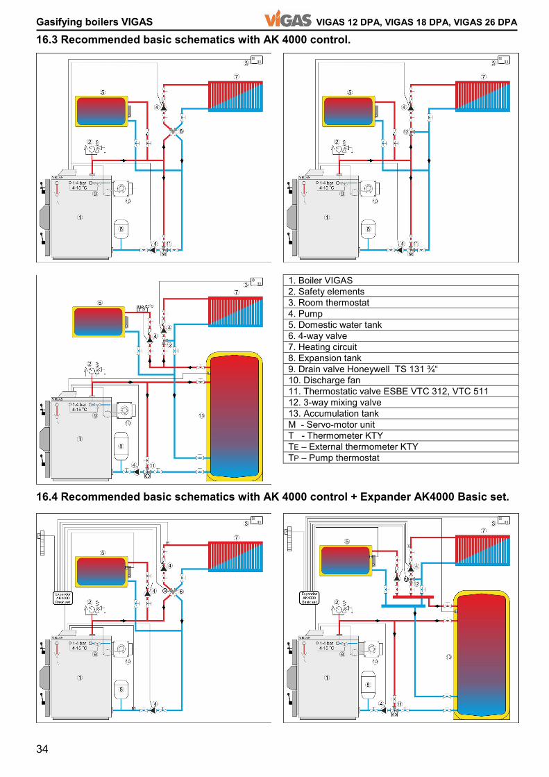
16.3 Recommended basic schematics with AK 4000 control. 1. Boiler VIGAS 2. Safety elements 3. Room thermostat 4. Pump 5. Domestic water tank 6. 4-way valve 7. Heating circuit 8. Expansion tank 9. Drain valve Honeywell TS 131 ¾“ 10. Discharge fan 11. Thermostatic valve ESBE VTC 312, VTC 511 12. 3-way mixing valve 13. Accumulation tank M - Servo-motor unit T - Thermometer KTY TE – External thermometer KTY TP – Pump thermostat 16.4 Recommended basic schematics with AK 4000 control + Expander AK4000 Basic set.
35
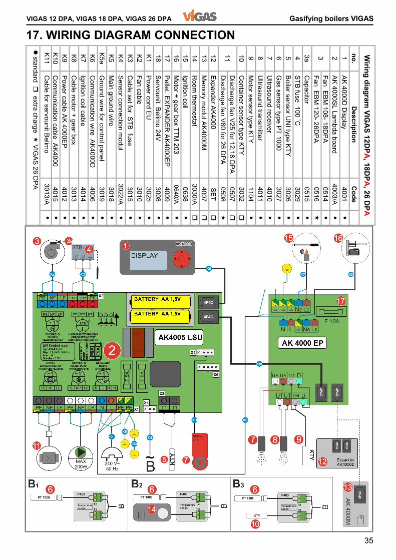
VIGAS 12 DPA, VIGAS 18 DPA, VIGAS 26 DPA Gasifying boilers VIGAS 17. WIRING DIAGRAM CONNECTION � standard � extra charge � VIGAS 26 DPA K11 K10 K9 K8 K7 K6 K5a K5 K4 K3 K2 K1 18 17 16 15 14 13 12 11 10 9 8 7 6 5 4 3a 3 2 1 no. Wiring diagram VIGAS 12DPA, 18DPA, 26 DPA
Cable for servounit Belimo Communication cable AK4000 Power cable AK 4000EP Cable motor + gear box Ignition coil cable Communication wire AK4000D Ground wire for control panel Main ground wire Sensor connection modul Cable set for STB fuse Fan cable Power cord EU Servounit Belimo 24V Pellet. EXPANDER AK4000EP Motor + gear box TTM 203 Ignition coil Room thermostat Memory modul AK4000M Expander AK4000 Discharge fan V80 for 26 DPA Discharge fan V25 for 12,18 DPA Container sensor type KTY Motor sensor type KTY Ultrasound transmitter Ultrasound receiver Gas sensor type PT 1000 Boiler sensor UNI type KTY STB fuse 100 °C Capacitor Fan EBM 120- 26DPA Fan EBM 108- 18DPA AK 4000SL Lambda board AK 4000D Display Description 3013/A 4015 4012 3013 4014 4006 3019 3018 3022/A 3015 3010 3025 3008 4009 0640/A 0638 3030/A 4007 SET 0508 0507 3032 1104 4011 4010 3027 3026 3029 0515 0516 0514 4003/A 4001 Code
� � � � � � � � � � � � � � � � � � � � � � � � � � � � � � � � �

36
Gasifying boilers VIGAS VIGAS 12 DPA, VIGAS 18 DPA, VIGAS 26 DPA
Records of electrical device connections (pump, discharge fan, room thermostat, expander, etc.) Date Device Service technician name Certificate no. Technician signature Records of warranty and after warranty service Date Service protocol number Service technician name Certificate number Technician signature Notes The list of most frequently used spare parts for VIGAS 18DPA (use „Code“ when ordering) Code Code 0102 Ceramic nozzle (3-hole) LAC pic.3/9 0101 Ceramic nozzle for VIGAS 12DPA 0104 Fire clay brick P4 (for iron ash) pic.3/12 0404 Heat exchanger seal for VIGAS 12DPA 3008 Servo Belimo 24V pic.3/39 0401 Gasket / Door seal 0405 Heat exchanger seal 0514 Fan EBM 108 pic.3/7 for VIGAS 12,18 DPA 0516 Fan EBM 120 pic.3/7 for VIGAS 26 DPA 0601 Handle (complete) 0633/A Burner 12,18,26 DPA (refractory steel) pic.3/24 0634/A Tourniquet blades pic.3/33 0636/C Feeder device 12,18,26 DPA complete 0637/A Feeder device pic.3/32 0638 Ignition coil pic.3/35 0640/A Motor + gearbox TTM 203 pic.3/34 0641/A Gear wheel (11z, 2x 32z) 0660/B Chain for pellet boiler short (40 cells) 0660/C Chain for pellet boiler long (42 cells) 0677 Fric. bearings EFOM Ø16 container,tourniquet
37
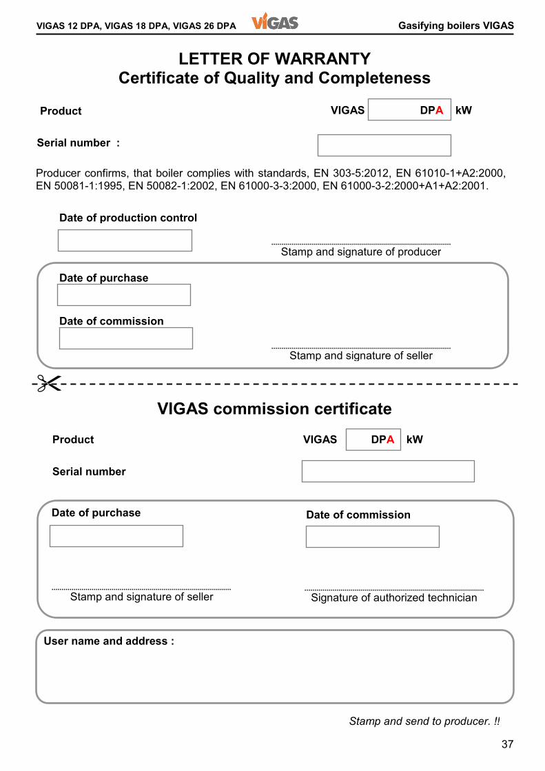
VIGAS 12 DPA, VIGAS 18 DPA, VIGAS 26 DPA Gasifying boilers VIGAS LETTER OF WARRANTY Certificate of Quality and Completeness VIGAS commission certificate Product Serial number : Producer confirms, that boiler complies with standards, EN 303-5:2012, EN 61010-1+A2:2000, EN 50081-1:1995, EN 50082-1:2002, EN 61000-3-3:2000, EN 61000-3-2:2000+A1+A2:2001. Date of production control Date of purchase Date of commission Stamp and signature of seller Stamp and signature of producer VIGAS DPA kW
Product VIGAS DPA kW Serial number User name and address : Date of purchase Date of commission Signature of authorized technician Stamp and signature of seller �
Stamp and send to producer. !!
38
Gasifying boilers VIGAS VIGAS 12 DPA, VIGAS 18 DPA, VIGAS 26 DPA Following operations were performed during commissioning:
� Thorough explanation of the boiler maintenance and service. � Boiler check before heating. � Provided burning test. � Complete and confirm data of warranty certificate. Boiler user signature Stamp and send to producer !!
Instruction and warranty condition for customer: � Claims regarding delivery completeness must be in accordance with Commercial law and Civil law of the supplier � Damage and defects during transportation must be claimed by buyer to the carrier at the time of delivery. � Warranty period is 24 months from the date of purchase. � Warranty is valid only if the boiler is commisioned by an authorised technician. � Warranty is valid only if the electric equipment is added according to regulation by authorized technician and recorded in relevant documents of connected devices. � Warranty applies only to the boiler construction, used material and complete boiler unit. Warranty does not apply: � Consumer material: gasket, exchanger seal,under fan seal, ceramic nozzle, heatproof lining and fire clay bricks. � Defects caused by customer. � Defects caused by incorrect assembly, improper operation or maintenance, or if the boiler is used for any other purpose as specified by producer. � Otherwise to claim quarantee applies by relevant provision of Civil law. Producer reserves the right to make changes under the product innovation.
�
39
VIGAS 12 DPA, VIGAS 18 DPA, VIGAS 26 DPA Gasifying boilers VIGAS Commission Regulation (EU) 2015/1189,implementing Directive 2009/125/EC of the European Parliament and of the Council with regard to ecodesign requirements for solid fuel boilers, commission Regulation (EU)2015/1189 supplementing Directive 2010/30/EU of the European Parliament and of the Council with regard to energy labelling of solid fuel boilers. Product information Symbol Unit VIGAS 12 DPA VIGAS 18 DPA VIGAS 26 DPA Energy efficiency class A++ A++ A++ Coefficient of energy EEI 126 127 130 Seasonal Energy efficiency heating area ηs % 87 87 89 Mode skoting Automatic Boiler is recommended to operated from a reservoir least L 500 800 Condensing boiler NO NO NO Combined boiler NO NO NO Preffered fuel Laminated wood in the form of pellets Charactericstic when operating with preffered fuel Useful thermal output at rated power Pn kW 12,0 18,0 26 Useful efficiency at rated power ηn % 90,54 91,87 92,83 Useful thermal output at minimum output / <50% Pp kW 3,9 4,4 6,6 Useful efficiency at minimum output ηn % 89,56 90,39 91,74 Own electricity consumption at rated power elmax kW 0,085 0,085 0,130 Own electricity at minimum output elmin kW 0,014 0,014 0,010 Own electricity consumption in standby mode PSB kW 0,001 0,001 0,001 Own electricity consuption in firing mode Pzap kW 1,773 1,773 1,693 Sezonne emissions heating area TČ1) PM mg/m3 24,0 13,2 21,0 Sezonne emissions heating area POZ1) OGC mg/m3 17,5 14,4 19,7 Sezonne emissions heating area CO1) CO mg/m3 421,3 260,9 360,5 Sezonne emissions heating area NOx1) NOx mg/m3 149,6 156,1 139,3 Characteristic when operating with substitute fuel Substiture fuel Chopped wood ,moisture content 20% Useful thermal output at rated power Pn kW 16,0 24,0 36,0 Useful efficiency at rated power ηn % 89,60 91,57 91,41 Useful thermal output at minimum output / <50% Pp kW 7,5 10,0 15,0 Useful efficiency at minimum output ηn % 88,19 90,95 90,10 Own electricity consumption at rated power elmax kW 0,014 0,030 0,038 Own electricity at minimum output elmin kW 0,003 0,005 0,012 Own electricity consumption in standby mode PSB kW 0,001 0,001 0,001 Season emissions of the heating space TČ2) PM mg/m3 29,5 42,8 22,7 Season emissions of the heating space OGC2) OGC mg/m3 26,3 28,3 28,2 Season emissions of the heating space CO2) CO mg/m3 436,7 370,6 456,4 Season emissions of the heating space NOx2) NOx mg/m3 185,7 221,6 150,0 1.Preffer fuel: Laminated wood in the form of pellets 2.Substitute fuel: Chopped wood, moisture content 20% .
Information sheet with data on the energy consumption of products VIGAS 12 DPA , 0032/104/2015 VIGAS 18 DPA , 0032/104/2015 VIGAS 26 DPA , 0063/104/2016
40
Gasifying boilers VIGAS VIGAS 12 DPA, VIGAS 18 DPA, VIGAS 26 DPA Gasifying boilers Producer: Pavel Vigaš - VIMAR M. Čulena 25 974 11 Banská Bystrica SLOVAKIA Production plant: Pavel Vigaš - VIMAR Príboj 796 976 13 Slovenská Ľupča SLOVAKIA tel.: 00421 48 4187 022 fax: 00421 48 4187 159 WWW.VIMAR.SK WWW.VIGAS.EU [email protected] Serial number
All technical changes are reserved by Pavel Vigaš VIMAR 2018 Displey ver.2.00 Pictures are illustrative and may differ from reality. 22.5.2018 12:26:07