WARNING! REMOTE START SYSTEMS ARE ONLY …02... · HOOD TILT SWITCH INSTALLATION ... polarity...
44
1/44 SK5W7J-19A361-AB © Copyright Ford 2005 2W7Z-16A901-AA Rev Date- 11/1/05 WARNING! REMOTE START SYSTEMS ARE ONLY APPLICABLE TO VEHICLES WITH AUTOMATIC TRANSMISSION! BOTH ORIGINAL KEYS ARE REQUIRED FOR ALL REMOTE START SYSTEMS ON VEHICLES EQUIPPED WITH SECURILOCK! EXPERT FITMENT REQUIRED Subject to Change Without Notice INSTALLATION AND TECHNICAL REFERENCE MANUAL ALL MODELS 2002 Use Caution - Personal Injury Use Caution - Vehicle Damage See shop manual TOOLS REQUIRED Silicone sealer D6AZ-19562-AA SILICONE RUBBER 1/4” 8mm 7mm 9/32” Technical Support (800) FORD-KEY For French Technical Support Rock Hebert (514) 973-2846 ! Important note 101871-2 Super Seal F3AZ-19515-SA
-
Upload
duongtuyen -
Category
Documents
-
view
217 -
download
2
Transcript of WARNING! REMOTE START SYSTEMS ARE ONLY …02... · HOOD TILT SWITCH INSTALLATION ... polarity...

1/44 SK5W7J-19A361-AB © Copyright Ford 20052W7Z-16A901-AA
Rev Date- 11/1/05
WARNING! REMOTE START SYSTEMS ARE ONLYAPPLICABLE TO VEHICLES WITH AUTOMATICTRANSMISSION!BOTH ORIGINAL KEYS ARE REQUIRED FOR ALLREMOTE START SYSTEMS ON VEHICLES EQUIPPEDWITH SECURILOCK!
EXPERT FITMENT REQUIRED
Subject to Change Without Notice
INSTALLATION AND TECHNICALREFERENCE MANUAL
ALL MODELS 2002 Use Caution -Personal Injury
Use Caution -Vehicle Damage
See shop manual
TOOLS REQUIRED
Silicone sealerD6AZ-19562-AA
SILICO
NERU
BBER
1/4”8mm 7mm
9/32”
Technical Support(800) FORD-KEYFor French Technical SupportRock Hebert (514) 973-2846
! Important note
101871-2
Super SealF3AZ-19515-SA
dkline
Text Box
SK5W7J-19A361-AB
2/44 SK5W7J-19A361-AB © Copyright Ford 20052W7Z-16A901-AA
Rev Date- 11/1/05
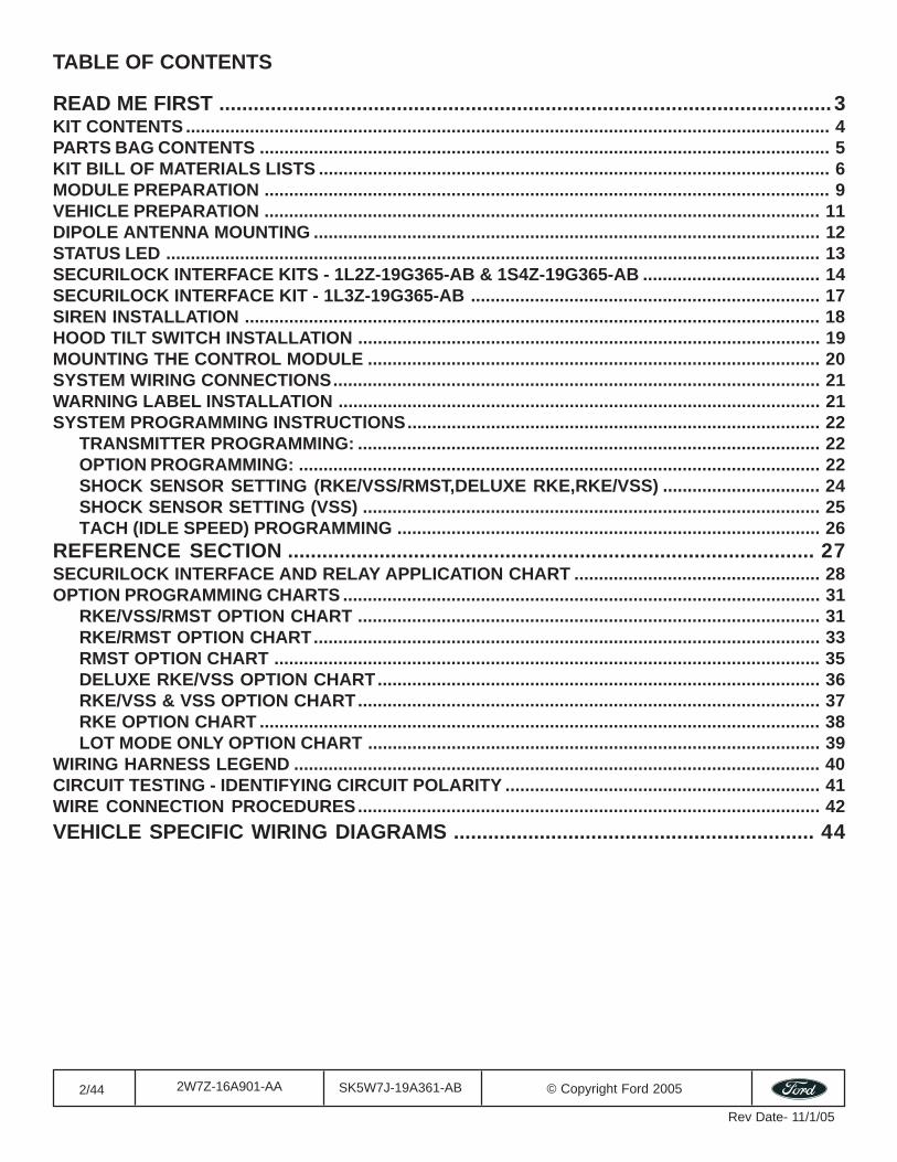
TABLE OF CONTENTS
READ ME FIRST ........................................................................................................... 3KIT CONTENTS ................................................................................................................................... 4PARTS BAG CONTENTS .................................................................................................................... 5KIT BILL OF MATERIALS LISTS ........................................................................................................ 6MODULE PREPARATION ................................................................................................................... 9VEHICLE PREPARATION ................................................................................................................. 11DIPOLE ANTENNA MOUNTING ....................................................................................................... 12STATUS LED ..................................................................................................................................... 13SECURILOCK INTERFACE KITS - 1L2Z-19G365-AB & 1S4Z-19G365-AB .................................... 14SECURILOCK INTERFACE KIT - 1L3Z-19G365-AB ....................................................................... 17SIREN INSTALLATION ..................................................................................................................... 18HOOD TILT SWITCH INSTALLATION .............................................................................................. 19MOUNTING THE CONTROL MODULE ............................................................................................ 20SYSTEM WIRING CONNECTIONS................................................................................................... 21WARNING LABEL INSTALLATION .................................................................................................. 21SYSTEM PROGRAMMING INSTRUCTIONS.................................................................................... 22
TRANSMITTER PROGRAMMING: .............................................................................................. 22OPTION PROGRAMMING: .......................................................................................................... 22SHOCK SENSOR SETTING (RKE/VSS/RMST,DELUXE RKE,RKE/VSS) ................................ 24SHOCK SENSOR SETTING (VSS) ............................................................................................. 25TACH (IDLE SPEED) PROGRAMMING ...................................................................................... 26
REFERENCE SECTION ............................................................................................ 27SECURILOCK INTERFACE AND RELAY APPLICATION CHART .................................................. 28OPTION PROGRAMMING CHARTS ................................................................................................. 31
RKE/VSS/RMST OPTION CHART .............................................................................................. 31RKE/RMST OPTION CHART....................................................................................................... 33RMST OPTION CHART ............................................................................................................... 35DELUXE RKE/VSS OPTION CHART.......................................................................................... 36RKE/VSS & VSS OPTION CHART.............................................................................................. 37RKE OPTION CHART .................................................................................................................. 38LOT MODE ONLY OPTION CHART ............................................................................................ 39
WIRING HARNESS LEGEND ........................................................................................................... 40CIRCUIT TESTING - IDENTIFYING CIRCUIT POLARITY ................................................................ 41WIRE CONNECTION PROCEDURES.............................................................................................. 42VEHICLE SPECIFIC WIRING DIAGRAMS ............................................................... 44
3/44 SK5W7J-19A361-AB © Copyright Ford 20052W7Z-16A901-AA
Rev Date- 11/1/05
READ ME FIRSTFor convenience this document uses short names when referring to a particular system or kit. The list below identifies theshort names used herein:Remote Start System with Deluxe Vehicle Security and Keyless Entry —> RKE/VSS/RMSTRemote Start System with Keyless Entry —> RKE/RMSTRemote Start System —> RMSTDeluxe Vehicle Security System with Keyless Entry —> Deluxe RKE/VSSVehicle Security System with Keyless Entry —> RKE/VSSVehicle Security System for Vehicles Equipped with Factory Keyless Entry —> VSSKeyless Entry System —> RKE
Navigating this document can be accomplished by: 1) using the buttons in the Acrobat toolbar, 2) clicking on thebookmark links in the bookmark pane to the left. (Clicking on the (+) symbols next to a bookmark will expand that bookmark,revealing additional selections) or 3) clicking on a topic in the table of contents located on page 2.
The most current version of this document can be accessed at www.mcdistributor.com and/or www.fmcdealer.com. As new/updated material becomes available, this document will be updated and posted on those sites.
This installation instruction covers the installation of all PowerCode based Convenience/Security and Remote start kits,therefore follow only the steps that apply to the kit that you are installing. For example, the Securilock interface kits are onlyused on systems that include remote start (RMST). Therefore, if you are installing a security only kit, skip the steps pertainingto the Securilock interface kit.
Vehicle wiring is subject to change. All possible efforts have been taken to ensure that the information contained herein isaccurate as of the revision dates indicated. As such, it is critical that vehicle circuits are tested prior to making anyconnections, to ensure that the proper vehicle circuit has been located.
Prior to beginning this installation it is recommended that you lower the drivers door window to prevent locking the keys in thevehicle.
The installation instructions are presented in three sections. The first section (which begins immediately following this page)contains installation instructions for the systems various components and tips for prepping the systems wiring harnesses.These steps are presented in a generic format. The procedures for these installation steps are basically the same regardlessof the model vehicle or system that you are working on. The drawings depicted in this section are for reference only and maynot reflect the vehicle on which you may be working.The second (reference) section contains the system option programming charts and various other reference type information.The last section represents vehicle specific wiring diagrams for each application. Within the wiring section for each vehicle,there are separate wiring diagrams for each different system. The vehicle specific wiring drawings are arranged in thefollowing order:1. RKE/VSS/RMST & RKE/RMST (in the same drawing) - Typically 4 pages;2. RMST - 1 page3. Deluxe RKE/VSS - 3 - 4 pages;4. RKE/VSS & RKE installation options - 1 page;5. VSS - Typically 1 page;6. Pre-load system wiring - 1 page;7. Fuse placement and vehicle specific programming requirements - 1 page.Vehicles that are equipped with 100% factory keyless entry will not have the RKE/VSS & RKE drawing. Some drawings willhave blank pages inserted to maintain the page order.
Prior to beginning your first installation of this product it is recommended that you:1. Thoroughly review and print out the first section;2. Skim through the reference section to become acquainted with the additional information that is available.Then, when going through the installation print out the vehicle specific wiring section and use as a reference during theinstallation.
4/44 SK5W7J-19A361-AB © Copyright Ford 20052W7Z-16A901-AA
Rev Date- 11/1/05
A
E
I
O
B
F
J
P
C
G
K
D
H
L
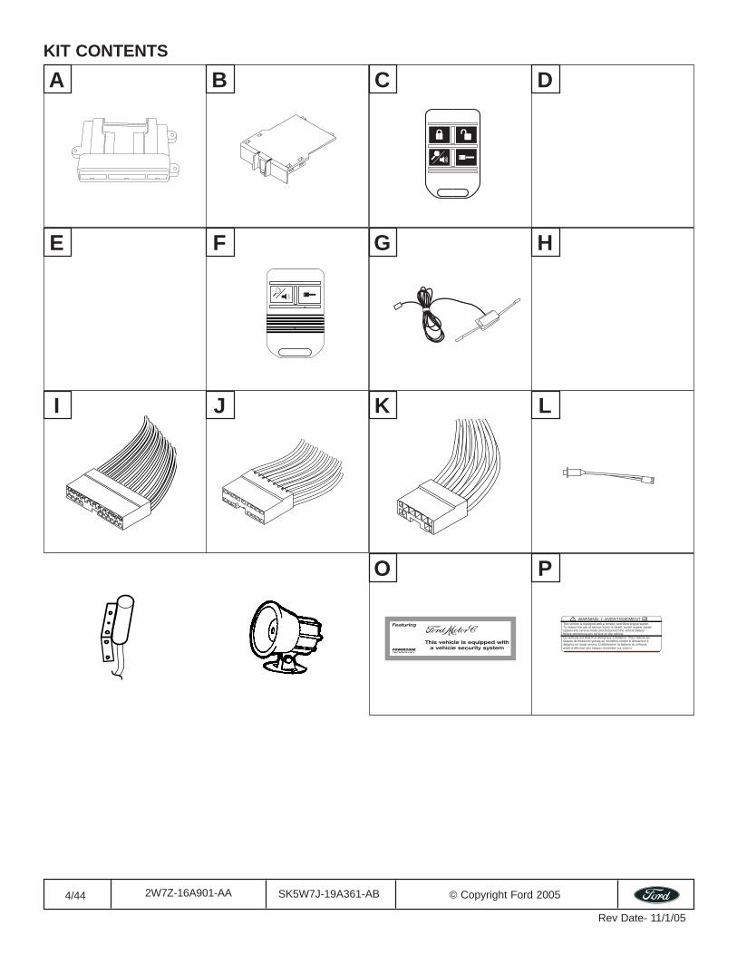
KIT CONTENTS
WARNING: / AVERTISSEMENTThis vehicle is equipped with a remote controlled engine starter. To reduce the risk of serious Injury or death, switch engine startersystem into service mode and disconnect the vehicle batterybefore performing any service on the vehicle.Ce véhicule est doté d'un démarreur à distance. Pour réduire les risques de blessures graves ou mortelles, mettre le démarreur à distance en mode service et débrancher la batterie du véhicule avant d'effectuer des travaux d'entretien sur celui-ci.
5/44 SK5W7J-19A361-AB © Copyright Ford 20052W7Z-16A901-AA
Rev Date- 11/1/05
S
W
AA
T
X
BB
U
Y
CC
V
Z
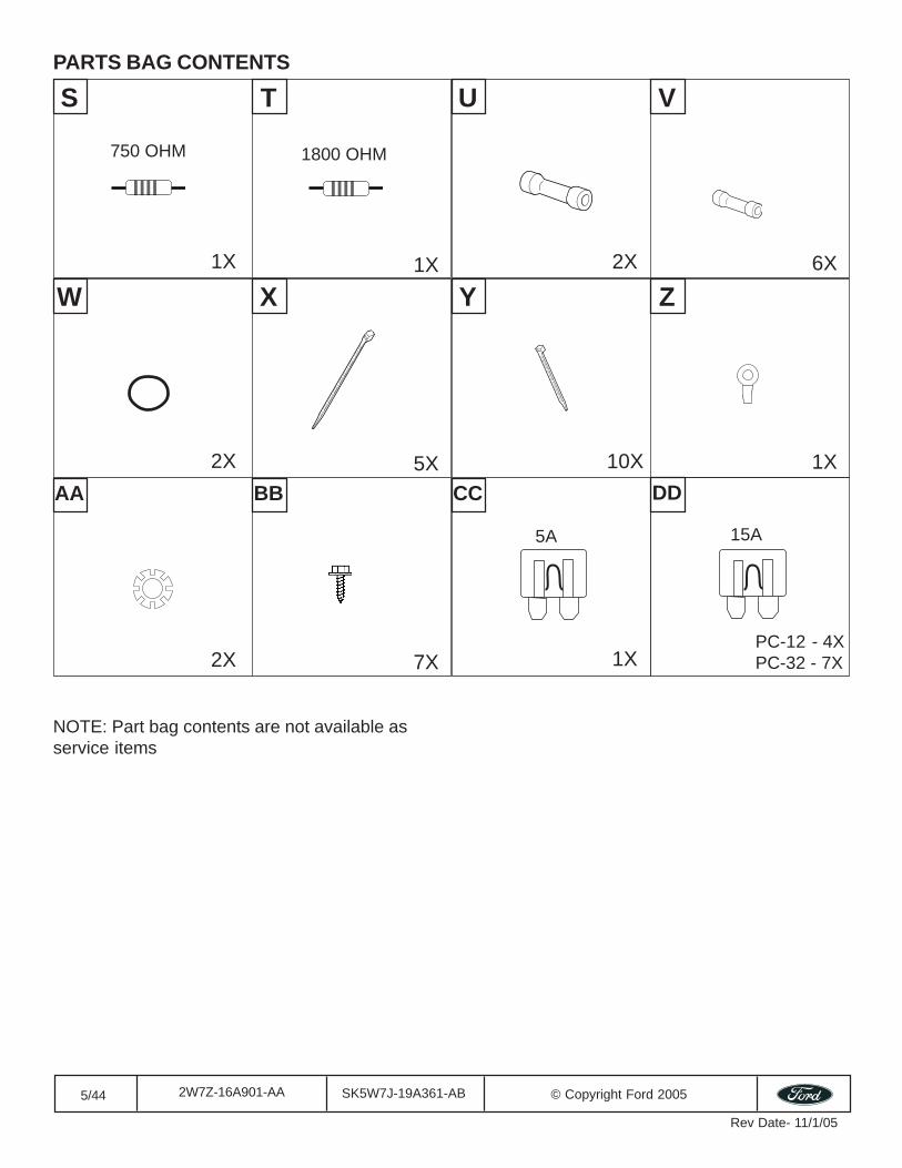
PARTS BAG CONTENTS
DD
5A 15A
750 OHM 1800 OHM
1X 1X 2X 6X
2X 5X 10X 1X
2X 7X 1XPC-12 - 4XPC-32 - 7X
NOTE: Part bag contents are not available asservice items
6/44 SK5W7J-19A361-AB © Copyright Ford 20052W7Z-16A901-AA
Rev Date- 11/1/05
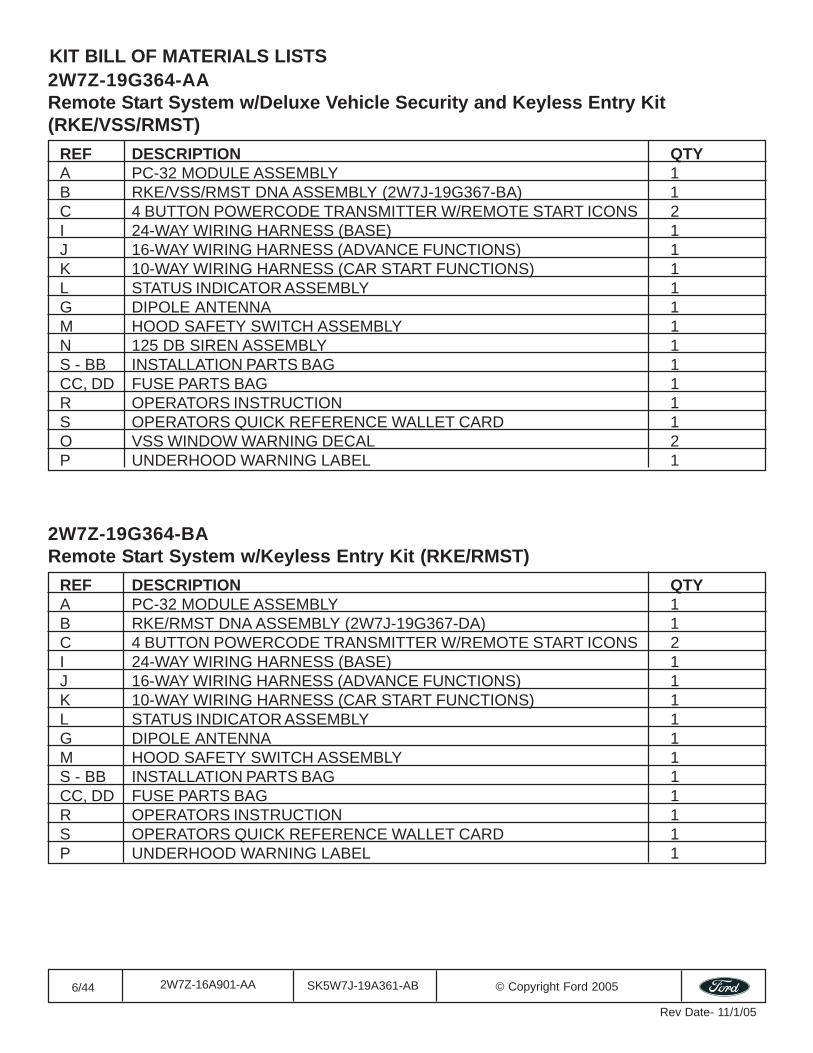
2W7Z-19G364-AARemote Start System w/Deluxe Vehicle Security and Keyless Entry Kit(RKE/VSS/RMST)
REF DESCRIPTION QTYA PC-32 MODULE ASSEMBLY 1B RKE/VSS/RMST DNA ASSEMBLY (2W7J-19G367-BA) 1C 4 BUTTON POWERCODE TRANSMITTER W/REMOTE START ICONS 2I 24-WAY WIRING HARNESS (BASE) 1J 16-WAY WIRING HARNESS (ADVANCE FUNCTIONS) 1K 10-WAY WIRING HARNESS (CAR START FUNCTIONS) 1L STATUS INDICATOR ASSEMBLY 1G DIPOLE ANTENNA 1M HOOD SAFETY SWITCH ASSEMBLY 1N 125 DB SIREN ASSEMBLY 1S - BB INSTALLATION PARTS BAG 1CC, DD FUSE PARTS BAG 1R OPERATORS INSTRUCTION 1S OPERATORS QUICK REFERENCE WALLET CARD 1O VSS WINDOW WARNING DECAL 2P UNDERHOOD WARNING LABEL 1
KIT BILL OF MATERIALS LISTS
2W7Z-19G364-BARemote Start System w/Keyless Entry Kit (RKE/RMST)
REF DESCRIPTION QTYA PC-32 MODULE ASSEMBLY 1B RKE/RMST DNA ASSEMBLY (2W7J-19G367-DA) 1C 4 BUTTON POWERCODE TRANSMITTER W/REMOTE START ICONS 2I 24-WAY WIRING HARNESS (BASE) 1J 16-WAY WIRING HARNESS (ADVANCE FUNCTIONS) 1K 10-WAY WIRING HARNESS (CAR START FUNCTIONS) 1L STATUS INDICATOR ASSEMBLY 1G DIPOLE ANTENNA 1M HOOD SAFETY SWITCH ASSEMBLY 1S - BB INSTALLATION PARTS BAG 1CC, DD FUSE PARTS BAG 1R OPERATORS INSTRUCTION 1S OPERATORS QUICK REFERENCE WALLET CARD 1P UNDERHOOD WARNING LABEL 1
7/44 SK5W7J-19A361-AB © Copyright Ford 20052W7Z-16A901-AA
Rev Date- 11/1/05
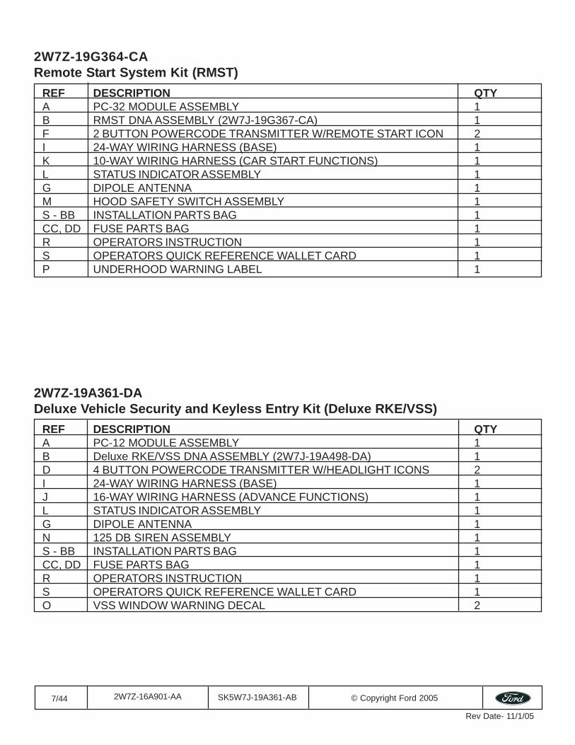
2W7Z-19G364-CARemote Start System Kit (RMST)
REF DESCRIPTION QTYA PC-32 MODULE ASSEMBLY 1B RMST DNA ASSEMBLY (2W7J-19G367-CA) 1F 2 BUTTON POWERCODE TRANSMITTER W/REMOTE START ICON 2I 24-WAY WIRING HARNESS (BASE) 1K 10-WAY WIRING HARNESS (CAR START FUNCTIONS) 1L STATUS INDICATOR ASSEMBLY 1G DIPOLE ANTENNA 1M HOOD SAFETY SWITCH ASSEMBLY 1S - BB INSTALLATION PARTS BAG 1CC, DD FUSE PARTS BAG 1R OPERATORS INSTRUCTION 1S OPERATORS QUICK REFERENCE WALLET CARD 1P UNDERHOOD WARNING LABEL 1
2W7Z-19A361-DADeluxe Vehicle Security and Keyless Entry Kit (Deluxe RKE/VSS)
REF DESCRIPTION QTYA PC-12 MODULE ASSEMBLY 1B Deluxe RKE/VSS DNA ASSEMBLY (2W7J-19A498-DA) 1D 4 BUTTON POWERCODE TRANSMITTER W/HEADLIGHT ICONS 2I 24-WAY WIRING HARNESS (BASE) 1J 16-WAY WIRING HARNESS (ADVANCE FUNCTIONS) 1L STATUS INDICATOR ASSEMBLY 1G DIPOLE ANTENNA 1N 125 DB SIREN ASSEMBLY 1S - BB INSTALLATION PARTS BAG 1CC, DD FUSE PARTS BAG 1R OPERATORS INSTRUCTION 1S OPERATORS QUICK REFERENCE WALLET CARD 1O VSS WINDOW WARNING DECAL 2
8/44 SK5W7J-19A361-AB © Copyright Ford 20052W7Z-16A901-AA
Rev Date- 11/1/05
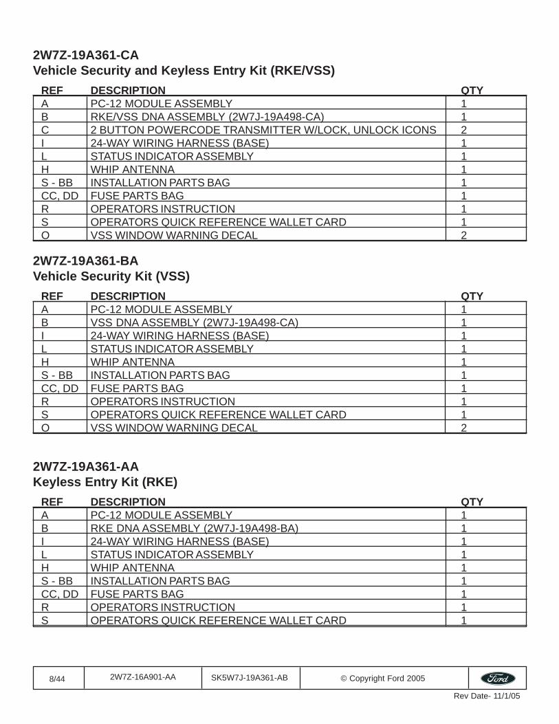
2W7Z-19A361-CAVehicle Security and Keyless Entry Kit (RKE/VSS)
REF DESCRIPTION QTYA PC-12 MODULE ASSEMBLY 1B RKE/VSS DNA ASSEMBLY (2W7J-19A498-CA) 1C 2 BUTTON POWERCODE TRANSMITTER W/LOCK, UNLOCK ICONS 2I 24-WAY WIRING HARNESS (BASE) 1L STATUS INDICATOR ASSEMBLY 1H WHIP ANTENNA 1S - BB INSTALLATION PARTS BAG 1CC, DD FUSE PARTS BAG 1R OPERATORS INSTRUCTION 1S OPERATORS QUICK REFERENCE WALLET CARD 1O VSS WINDOW WARNING DECAL 2
2W7Z-19A361-BAVehicle Security Kit (VSS)
REF DESCRIPTION QTYA PC-12 MODULE ASSEMBLY 1B VSS DNA ASSEMBLY (2W7J-19A498-CA) 1I 24-WAY WIRING HARNESS (BASE) 1L STATUS INDICATOR ASSEMBLY 1H WHIP ANTENNA 1S - BB INSTALLATION PARTS BAG 1CC, DD FUSE PARTS BAG 1R OPERATORS INSTRUCTION 1S OPERATORS QUICK REFERENCE WALLET CARD 1O VSS WINDOW WARNING DECAL 2
2W7Z-19A361-AAKeyless Entry Kit (RKE)
REF DESCRIPTION QTYA PC-12 MODULE ASSEMBLY 1B RKE DNA ASSEMBLY (2W7J-19A498-BA) 1I 24-WAY WIRING HARNESS (BASE) 1L STATUS INDICATOR ASSEMBLY 1H WHIP ANTENNA 1S - BB INSTALLATION PARTS BAG 1CC, DD FUSE PARTS BAG 1R OPERATORS INSTRUCTION 1S OPERATORS QUICK REFERENCE WALLET CARD 1
9/44 SK5W7J-19A361-AB © Copyright Ford 20052W7Z-16A901-AA
Rev Date- 11/1/05
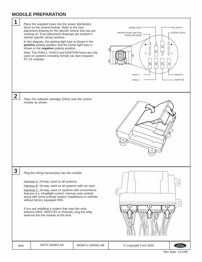
MODULE PREPARATION
Place the supplied fuses into the power distributionblock on the control module. Refer to the fuseplacement drawing for the specific vehicle that you areworking on. Fuse placement drawings are located invehicle specific wiring sections.In this diagram, the parking light fuse is shown in thepositive polarity position and the Dome light fuse isshown in the negative polarity position.Note: The HVAC1, HVAC2 and IGNITION fuses are onlyused on systems including remote car start (requiresPC-32 module).
Place the software cartridge (DNA) onto the controlmodule as shown.
Plug the wiring harness(es) into the module.
Harness A: 24-way, used on all systems;Harness B: 10-way, used on all systems with car start;Harness C: 16-way, used on systems with conveniencefeatures (i.e. Headlight control, memory seat control)along with some preload system installations in vehicleswithout factory equipped RKE.
If you are installing a system that uses the whipantenna (RKE, RKE/VSS or Preload), plug the whipantenna into the module at this time.
1
515151515 15 15
15
51515
151515
-+
-+
HVAC 1
HVAC 2
MAIN B+
IGNITION
DOME LIGHT
DRIVER DOOR UNLOCK/TRUNK RELEASE
PK LIGHTS
DOOR LOCKS
C BA
2
3
10/44 SK5W7J-19A361-AB © Copyright Ford 20052W7Z-16A901-AA
Rev Date- 11/1/05
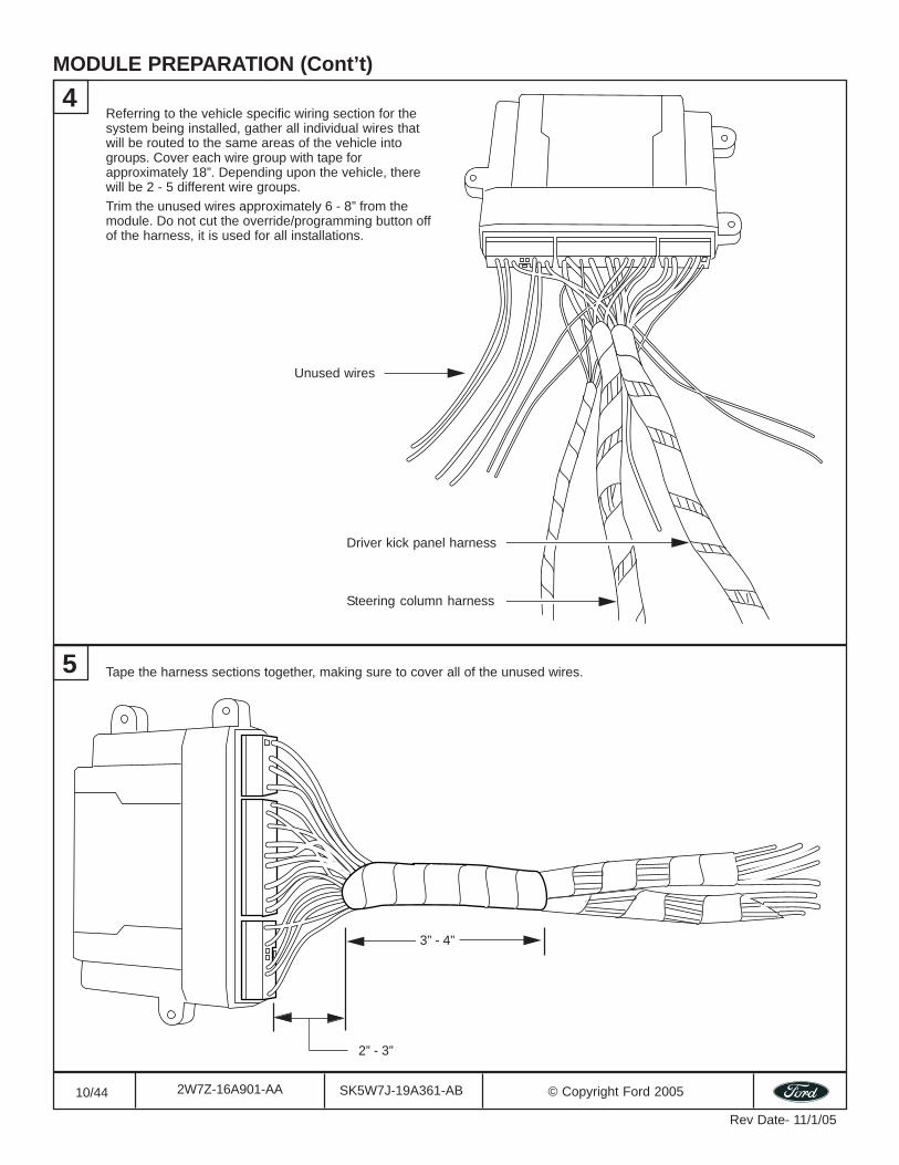
MODULE PREPARATION (Cont’t)
Tape the harness sections together, making sure to cover all of the unused wires.
4
5
Unused wires
Steering column harness
Driver kick panel harness
Referring to the vehicle specific wiring section for thesystem being installed, gather all individual wires thatwill be routed to the same areas of the vehicle intogroups. Cover each wire group with tape forapproximately 18”. Depending upon the vehicle, therewill be 2 - 5 different wire groups.Trim the unused wires approximately 6 - 8” from themodule. Do not cut the override/programming button offof the harness, it is used for all installations.
3” - 4”
2” - 3”
11/44 SK5W7J-19A361-AB © Copyright Ford 20052W7Z-16A901-AA
Rev Date- 11/1/05
VEHICLE PREPARATION
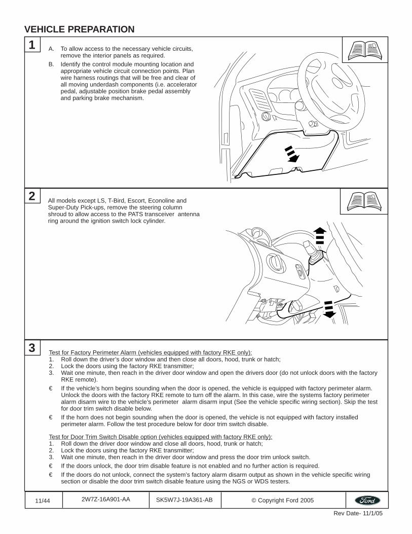
All models except LS, T-Bird, Escort, Econoline andSuper-Duty Pick-ups, remove the steering columnshroud to allow access to the PATS transceiver antennaring around the ignition switch lock cylinder.
A. To allow access to the necessary vehicle circuits,remove the interior panels as required.
B. Identify the control module mounting location andappropriate vehicle circuit connection points. Planwire harness routings that will be free and clear ofall moving underdash components (i.e. acceleratorpedal, adjustable position brake pedal assemblyand parking brake mechanism.
1
2
3 Test for Factory Perimeter Alarm (vehicles equipped with factory RKE only):1. Roll down the driver’s door window and then close all doors, hood, trunk or hatch;2. Lock the doors using the factory RKE transmitter;3. Wait one minute, then reach in the driver door window and open the drivers door (do not unlock doors with the factory
RKE remote).€ If the vehicle’s horn begins sounding when the door is opened, the vehicle is equipped with factory perimeter alarm.
Unlock the doors with the factory RKE remote to turn off the alarm. In this case, wire the systems factory perimeteralarm disarm wire to the vehicle’s perimeter alarm disarm input (See the vehicle specific wiring section). Skip the testfor door trim switch disable below.
€ If the horn does not begin sounding when the door is opened, the vehicle is not equipped with factory installedperimeter alarm. Follow the test procedure below for door trim switch disable.
Test for Door Trim Switch Disable option (vehicles equipped with factory RKE only):1. Roll down the driver door window and close all doors, hood, trunk or hatch;2. Lock the doors using the factory RKE transmitter;3. Wait one minute, then reach in the driver door window and press the door trim unlock switch.€ If the doors unlock, the door trim disable feature is not enabled and no further action is required.€ If the doors do not unlock, connect the system’s factory alarm disarm output as shown in the vehicle specific wiring
section or disable the door trim switch disable feature using the NGS or WDS testers.
12/44 SK5W7J-19A361-AB © Copyright Ford 20052W7Z-16A901-AA
Rev Date- 11/1/05
DIPOLE ANTENNA MOUNTING
2
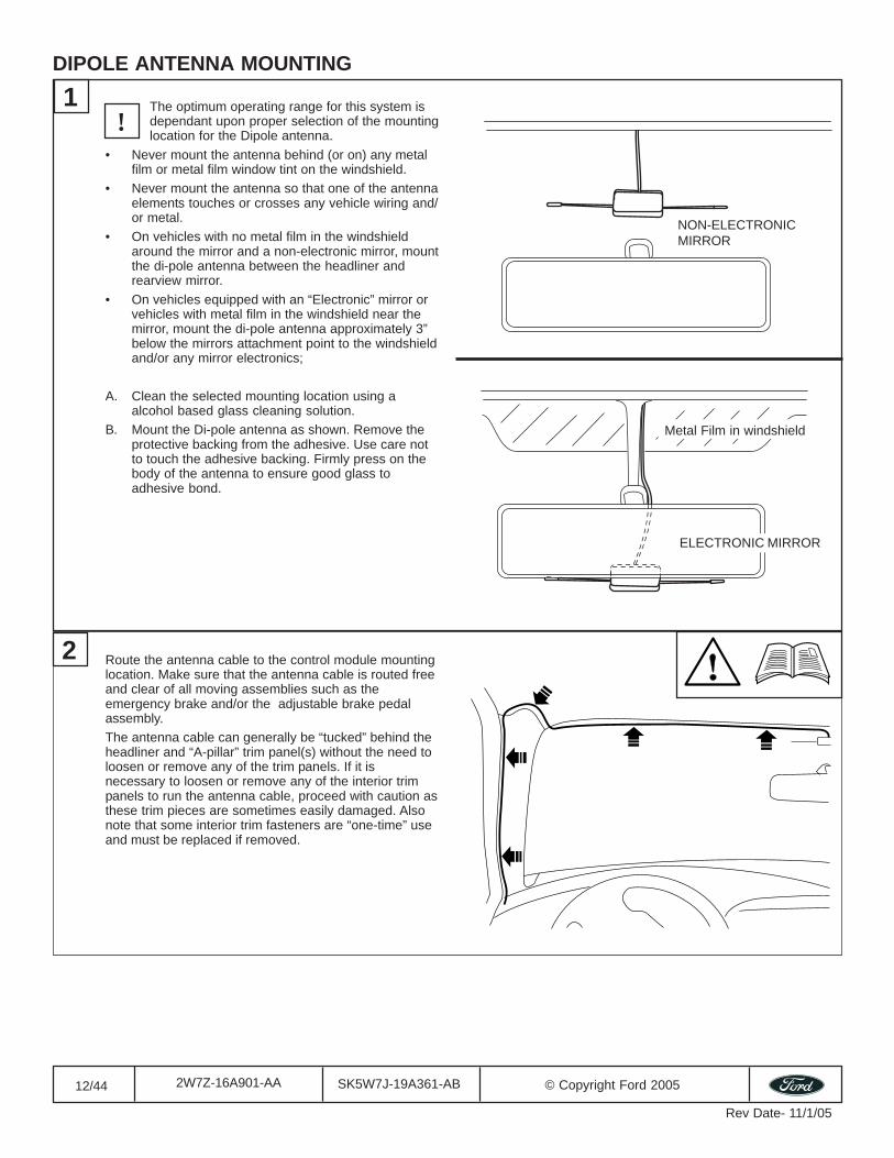
1 The optimum operating range for this system isdependant upon proper selection of the mountinglocation for the Dipole antenna.
• Never mount the antenna behind (or on) any metalfilm or metal film window tint on the windshield.
• Never mount the antenna so that one of the antennaelements touches or crosses any vehicle wiring and/or metal.
• On vehicles with no metal film in the windshieldaround the mirror and a non-electronic mirror, mountthe di-pole antenna between the headliner andrearview mirror.
• On vehicles equipped with an “Electronic” mirror orvehicles with metal film in the windshield near themirror, mount the di-pole antenna approximately 3”below the mirrors attachment point to the windshieldand/or any mirror electronics;
A. Clean the selected mounting location using aalcohol based glass cleaning solution.
B. Mount the Di-pole antenna as shown. Remove theprotective backing from the adhesive. Use care notto touch the adhesive backing. Firmly press on thebody of the antenna to ensure good glass toadhesive bond.
ELECTRONIC MIRROR
NON-ELECTRONICMIRROR
Route the antenna cable to the control module mountinglocation. Make sure that the antenna cable is routed freeand clear of all moving assemblies such as theemergency brake and/or the adjustable brake pedalassembly.The antenna cable can generally be “tucked” behind theheadliner and “A-pillar” trim panel(s) without the need toloosen or remove any of the trim panels. If it isnecessary to loosen or remove any of the interior trimpanels to run the antenna cable, proceed with caution asthese trim pieces are sometimes easily damaged. Alsonote that some interior trim fasteners are “one-time” useand must be replaced if removed.
!
Metal Film in windshield
13/44 SK5W7J-19A361-AB © Copyright Ford 20052W7Z-16A901-AA
Rev Date- 11/1/05
STATUS LED
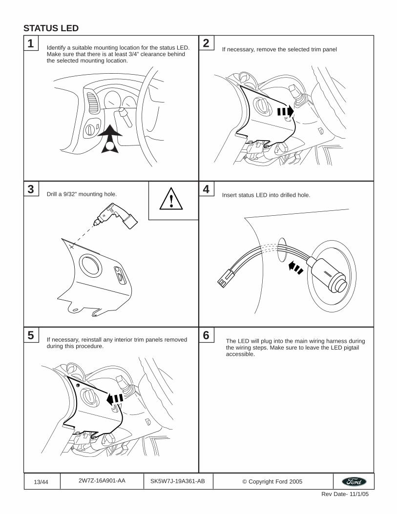
Identify a suitable mounting location for the status LED.Make sure that there is at least 3/4” clearance behindthe selected mounting location.
1
Drill a 9/32” mounting hole.
If necessary, remove the selected trim panel2
3 4Insert status LED into drilled hole.
5 If necessary, reinstall any interior trim panels removedduring this procedure.
6 The LED will plug into the main wiring harness duringthe wiring steps. Make sure to leave the LED pigtailaccessible.
14/44 SK5W7J-19A361-AB © Copyright Ford 20052W7Z-16A901-AA
Rev Date- 11/1/05
SECURILOCK INTERFACE KITS - 1L2Z-19G365-AB & 1S4Z-19G365-AB
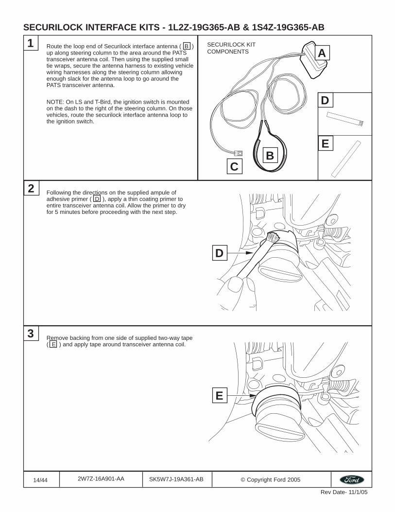
Route the loop end of Securilock interface antenna ( B )up along steering column to the area around the PATStransceiver antenna coil. Then using the supplied smalltie wraps, secure the antenna harness to existing vehiclewiring harnesses along the steering column allowingenough slack for the antenna loop to go around thePATS transceiver antenna.
NOTE: On LS and T-Bird, the ignition switch is mountedon the dash to the right of the steering column. On thosevehicles, route the securilock interface antenna loop tothe ignition switch.
1
Following the directions on the supplied ampule ofadhesive primer ( D ), apply a thin coating primer toentire transceiver antenna coil. Allow the primer to dryfor 5 minutes before proceeding with the next step.
2
Remove backing from one side of supplied two-way tape( E ) and apply tape around transceiver antenna coil.
3
D
E
A
BC
D
E
SECURILOCK KITCOMPONENTS
15/44 SK5W7J-19A361-AB © Copyright Ford 20052W7Z-16A901-AA
Rev Date- 11/1/05
SECURILOCK INTERFACE KITS - 1L2Z-19G365-AB & 1S4Z-19G365-AB (Con’t)
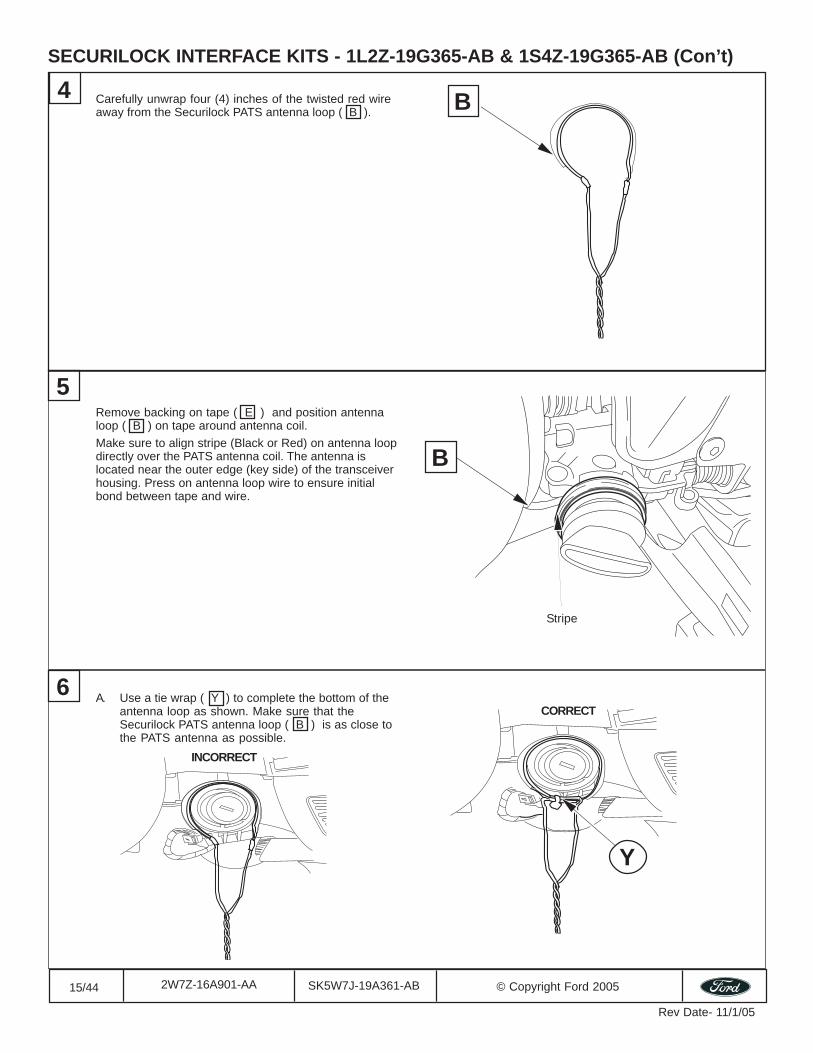
Carefully unwrap four (4) inches of the twisted red wireaway from the Securilock PATS antenna loop ( B ).
4
5
6
B
A. Use a tie wrap ( Y ) to complete the bottom of theantenna loop as shown. Make sure that theSecurilock PATS antenna loop ( B ) is as close tothe PATS antenna as possible.
B
Stripe
Remove backing on tape ( E ) and position antennaloop ( B ) on tape around antenna coil.Make sure to align stripe (Black or Red) on antenna loopdirectly over the PATS antenna coil. The antenna islocated near the outer edge (key side) of the transceiverhousing. Press on antenna loop wire to ensure initialbond between tape and wire.
Y
CORRECT
INCORRECT
16/44 SK5W7J-19A361-AB © Copyright Ford 20052W7Z-16A901-AA
Rev Date- 11/1/05
SECURILOCK INTERFACE KITS - 1L2Z-19G365-AB & 1S4Z-19G365-AB (Con’t)
Vehicle wiring harness
XA
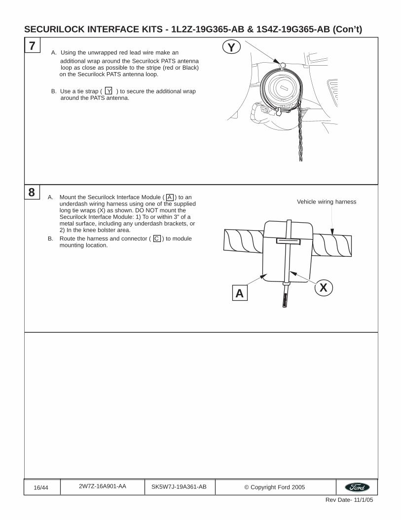
A. Using the unwrapped red lead wire make an additional wrap around the Securilock PATS antenna loop as close as possible to the stripe (red or Black) on the Securilock PATS antenna loop.
B. Use a tie strap ( Y ) to secure the additional wrap around the PATS antenna.
A. Mount the Securilock Interface Module ( A ) to anunderdash wiring harness using one of the suppliedlong tie wraps (X) as shown. DO NOT mount theSecurilock Interface Module: 1) To or within 3” of ametal surface, including any underdash brackets, or2) In the knee bolster area.
B. Route the harness and connector ( C ) to modulemounting location.
Y7
8
17/44 SK5W7J-19A361-AB © Copyright Ford 20052W7Z-16A901-AA
Rev Date- 11/1/05
SECURILOCK INTERFACE KIT - 1L3Z-19G365-AB
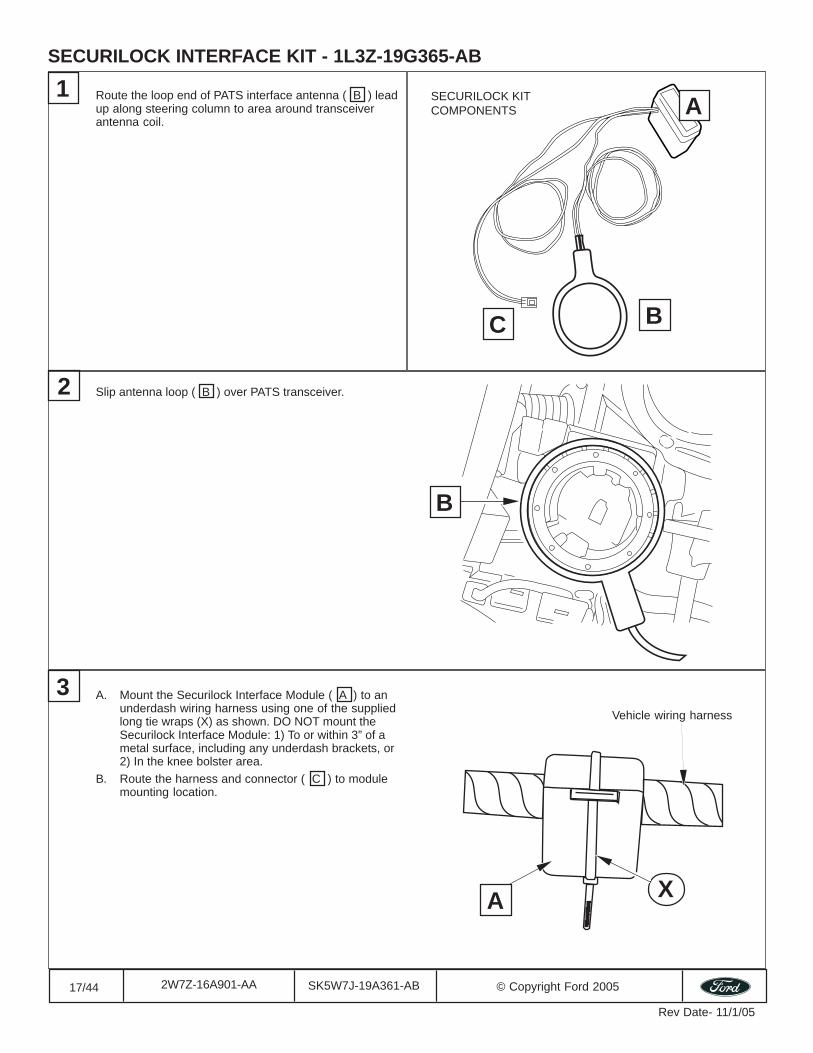
Route the loop end of PATS interface antenna ( B ) leadup along steering column to area around transceiverantenna coil.
Slip antenna loop ( B ) over PATS transceiver.2
3
1A
BC
B
Vehicle wiring harness
XA
SECURILOCK KITCOMPONENTS
A. Mount the Securilock Interface Module ( A ) to anunderdash wiring harness using one of the suppliedlong tie wraps (X) as shown. DO NOT mount theSecurilock Interface Module: 1) To or within 3” of ametal surface, including any underdash brackets, or2) In the knee bolster area.
B. Route the harness and connector ( C ) to modulemounting location.
18/44 SK5W7J-19A361-AB © Copyright Ford 20052W7Z-16A901-AA
Rev Date- 11/1/05
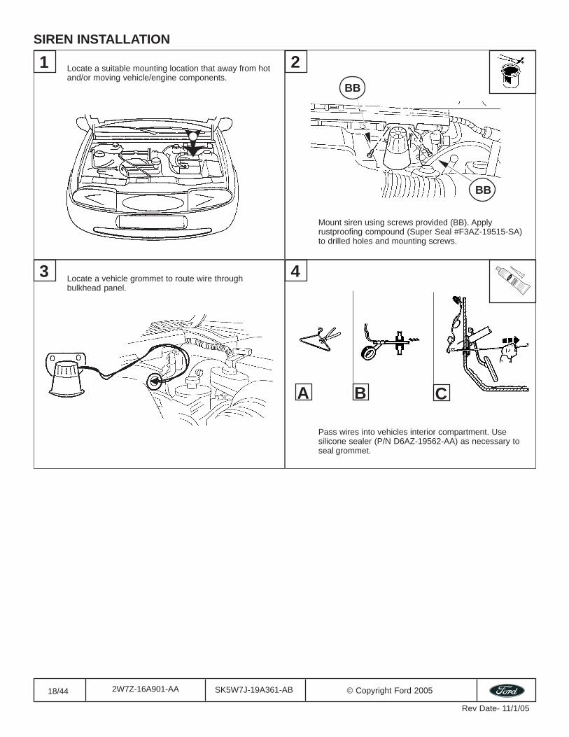
Locate a suitable mounting location that away from hotand/or moving vehicle/engine components.
SIREN INSTALLATION
Mount siren using screws provided (BB). Applyrustproofing compound (Super Seal #F3AZ-19515-SA)to drilled holes and mounting screws.
Locate a vehicle grommet to route wire throughbulkhead panel.
1 2
Pass wires into vehicles interior compartment. Usesilicone sealer (P/N D6AZ-19562-AA) as necessary toseal grommet.
3 4
A B C
BB
BB
SILICO
NERU
BBER
19/44 SK5W7J-19A361-AB © Copyright Ford 20052W7Z-16A901-AA
Rev Date- 11/1/05
2x
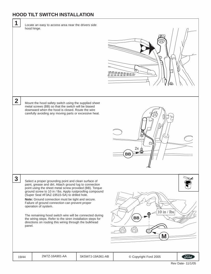
Locate an easy to access area near the drivers sidehood hinge.
Mount the hood safety switch using the supplied sheetmetal screws (BB) so that the switch will be biaseddownward when the hood is closed. Route the wirecarefully avoiding any moving parts or excessive heat.
Select a proper grounding point and clean surface ofpaint, grease and dirt. Attach ground lug to connectionpoint using the sheet metal screw provided (BB). Torqueground screw to 10 in / lbs. Apply rustproofing compound(Super Seal #F3AZ-19515-SA) to drilled hole.Note: Ground connection must be tight and secure.Failure of ground connection can prevent properoperation of system.
The remaining hood switch wire will be connected duringthe wiring steps. Refer to the siren installation steps fordirections on routing this wiring through the bulkheadpanel.
1
2
3
HOOD TILT SWITCH INSTALLATION
10 in / lbs
M
BB
BB
20/44 SK5W7J-19A361-AB © Copyright Ford 20052W7Z-16A901-AA
Rev Date- 11/1/05
MOUNTING THE CONTROL MODULE
1
3
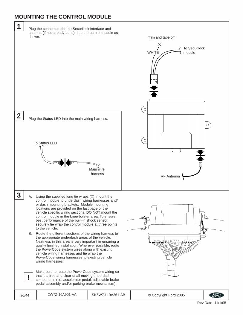
To Securilockmodule
Trim and tape off
WHITE
RF Antenna
A. Using the supplied long tie wraps (X), mount thecontrol module to underdash wiring harnesses and/or dash mounting brackets. Module mountinglocations are provided on the last page of thevehicle specific wiring sections. DO NOT mount thecontrol module in the knee bolster area. To ensurebest performance of the built-in shock sensor,securely tie wrap the control module at three pointsto the vehicle.
B. Route the different sections of the wiring harness tothe appropriate underdash areas of the vehicle.Neatness in this area is very important in ensuring aquality finished installation. Wherever possible, routethe PowerCode system wires along with existingvehicle wiring harnesses and tie wrap thePowerCode wiring harnesses to existing vehiclewiring harnesses.
Make sure to route the PowerCode system wiring sothat it is free and clear of all moving underdashcomponents (i.e. accelerator pedal, adjustable brakepedal assembly and/or parking brake mechanism).
Plug the connectors for the Securilock interface andantenna (if not already done) into the control module asshown.
To Status LED
Main wire harness
2 Plug the Status LED into the main wiring harness.
!
21/44 SK5W7J-19A361-AB © Copyright Ford 20052W7Z-16A901-AA
Rev Date- 11/1/05
SYSTEM WIRING CONNECTIONS
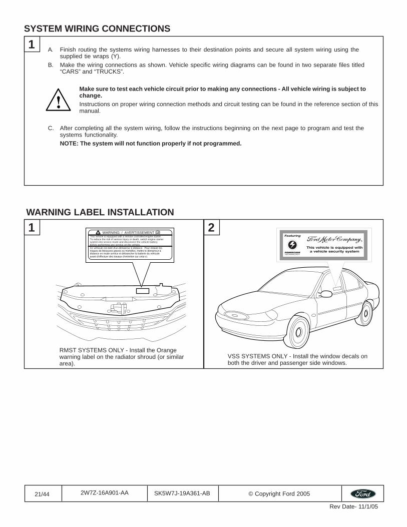
1 A. Finish routing the systems wiring harnesses to their destination points and secure all system wiring using thesupplied tie wraps (Y).
B. Make the wiring connections as shown. Vehicle specific wiring diagrams can be found in two separate files titled“CARS” and “TRUCKS”.
Make sure to test each vehicle circuit prior to making any connections - All vehicle wiring is subject tochange.Instructions on proper wiring connection methods and circuit testing can be found in the reference section of thismanual.
C. After completing all the system wiring, follow the instructions beginning on the next page to program and test thesystems functionality.NOTE: The system will not function properly if not programmed.
RMST SYSTEMS ONLY - Install the Orangewarning label on the radiator shroud (or similararea).
VSS SYSTEMS ONLY - Install the window decals onboth the driver and passenger side windows.
WARNING: / AVERTISSEMENTThis vehicle is equipped with a remote controlled engine starter. To reduce the risk of serious Injury or death, switch engine startersystem into service mode and disconnect the vehicle batterybefore performing any service on the vehicle.Ce véhicule est doté d'un démarreur à distance. Pour réduire les risques de blessures graves ou mortelles, mettre le démarreur à distance en mode service et débrancher la batterie du véhicule avant d'effectuer des travaux d'entretien sur celui-ci.
1 2WARNING LABEL INSTALLATION
22/44 SK5W7J-19A361-AB © Copyright Ford 20052W7Z-16A901-AA
Rev Date- 11/1/05
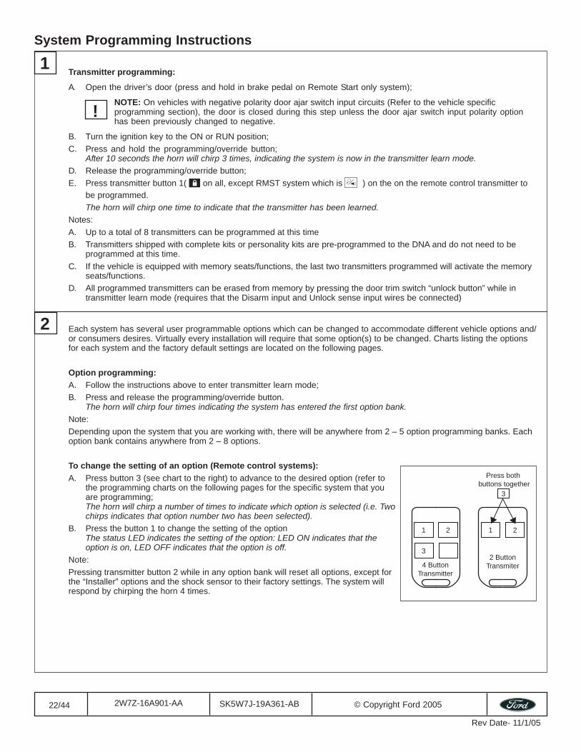
Transmitter programming:
A. Open the driver’s door (press and hold in brake pedal on Remote Start only system);
NOTE: On vehicles with negative polarity door ajar switch input circuits (Refer to the vehicle specificprogramming section), the door is closed during this step unless the door ajar switch input polarity optionhas been previously changed to negative.
B. Turn the ignition key to the ON or RUN position;C. Press and hold the programming/override button;
After 10 seconds the horn will chirp 3 times, indicating the system is now in the transmitter learn mode.
D. Release the programming/override button;E. Press transmitter button 1( on all, except RMST system which is ) on the on the remote control transmitter to
be programmed.The horn will chirp one time to indicate that the transmitter has been learned.
Notes:A. Up to a total of 8 transmitters can be programmed at this timeB. Transmitters shipped with complete kits or personality kits are pre-programmed to the DNA and do not need to be
programmed at this time.C. If the vehicle is equipped with memory seats/functions, the last two transmitters programmed will activate the memory
seats/functions.D. All programmed transmitters can be erased from memory by pressing the door trim switch “unlock button” while in
transmitter learn mode (requires that the Disarm input and Unlock sense input wires be connected)
System Programming Instructions
1
Each system has several user programmable options which can be changed to accommodate different vehicle options and/or consumers desires. Virtually every installation will require that some option(s) to be changed. Charts listing the optionsfor each system and the factory default settings are located on the following pages.
Option programming:A. Follow the instructions above to enter transmitter learn mode;B. Press and release the programming/override button.
The horn will chirp four times indicating the system has entered the first option bank.
Note:Depending upon the system that you are working with, there will be anywhere from 2 – 5 option programming banks. Eachoption bank contains anywhere from 2 – 8 options.
To change the setting of an option (Remote control systems):A. Press button 3 (see chart to the right) to advance to the desired option (refer to
the programming charts on the following pages for the specific system that youare programming;The horn will chirp a number of times to indicate which option is selected (i.e. Twochirps indicates that option number two has been selected).
B. Press the button 1 to change the setting of the optionThe status LED indicates the setting of the option: LED ON indicates that theoption is on, LED OFF indicates that the option is off.
Note:Pressing transmitter button 2 while in any option bank will reset all options, except forthe “Installer” options and the shock sensor to their factory settings. The system willrespond by chirping the horn 4 times.
2
1 2 1 2
3
3
4 ButtonTransmitter
2 ButtonTransmiter
Press both buttons together
!
23/44 SK5W7J-19A361-AB © Copyright Ford 20052W7Z-16A901-AA
Rev Date- 11/1/05
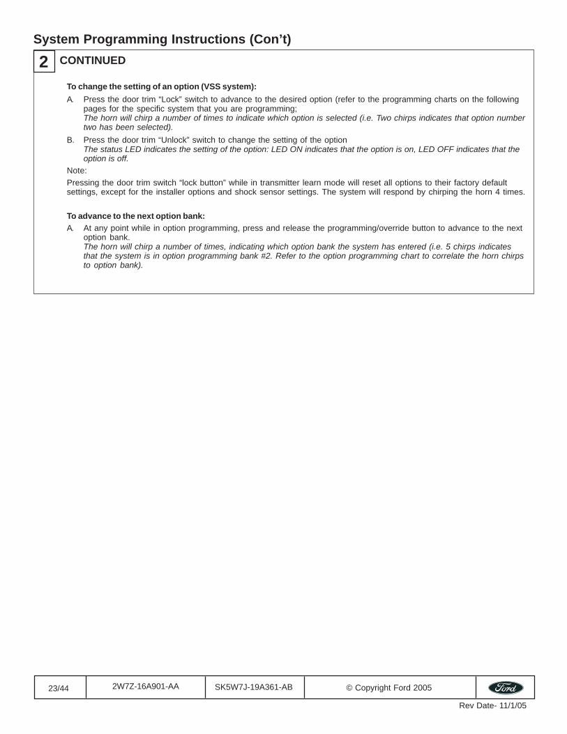
To change the setting of an option (VSS system):A. Press the door trim “Lock” switch to advance to the desired option (refer to the programming charts on the following
pages for the specific system that you are programming;The horn will chirp a number of times to indicate which option is selected (i.e. Two chirps indicates that option numbertwo has been selected).
B. Press the door trim “Unlock” switch to change the setting of the optionThe status LED indicates the setting of the option: LED ON indicates that the option is on, LED OFF indicates that theoption is off.
Note:Pressing the door trim switch “lock button” while in transmitter learn mode will reset all options to their factory defaultsettings, except for the installer options and shock sensor settings. The system will respond by chirping the horn 4 times.
To advance to the next option bank:A. At any point while in option programming, press and release the programming/override button to advance to the next
option bank.The horn will chirp a number of times, indicating which option bank the system has entered (i.e. 5 chirps indicatesthat the system is in option programming bank #2. Refer to the option programming chart to correlate the horn chirpsto option bank).
System Programming Instructions (Con’t)
2 CONTINUED

24/44 SK5W7J-19A361-AB © Copyright Ford 20052W7Z-16A901-AA
Rev Date- 11/1/05
3 Shock sensor setting (not applicable to RKE, RMST or RKE/RMST systems)
A). How to Properly Adjust Shock (Lite Touch & Full Shock) SensorSettings Using a Transmitter (RKE/VSS/RMST, Deluxe RKE/VSS,RKE/VSS - see next page for VSS instructions):
Note: Powercode Systems with Alarm Feature contain one internal shock sensor with two different settings, LiteTouch and Full Shock. When the vehicle is armed, the force which chirps the horn due to impact is determined bythe Lite Touch level setting. When the vehicle is armed, the force at which sounds the alarm due to impact isdetermined by the Full Shock level setting. THE FULL SHOCK LEVEL SHOULD ALWAYS BE LESS SENSITIVE THANLITE TOUCH LEVEL.
#1). Locate Override button coming from Powercode Module (usually mounted in driver’s side kick panel or under dash).
#2). Open driver’s door and turn key to ON position.
#3). Press and hold Override Button until horn chirps.
#4). Press again until FOUR chirps are heard. This is option bank #1.
#5). Press button THREE (scroll down) to select first option in option bank #1. The horn will chirp once to indicate first option in option bank #1.
This is the Lite Touch Adjustment Programming Option. When in this programming option the vehicle will CHIRP thehorn when an impact is detected.
To test and adjust current sensitivity level: Start with a light tap on outer rim of steering wheel with open palm of hand.Gradually increase force of tap until horn chirp is detected. This should be set to chirp at a Light to Medium Impactlevel.
Pressing UNLOCK button on Powercode transmitter will decrease sensitivity. Pressing LOCK will increase sensitivity.
#6). When properly adjusted Press button THREE (scroll down) to select second option in option bank #1. The horn willchirp twice to indicate second option in option bank #1.
This is the Full Shock Adjustment Programming Option. When in this programming option the vehicle will CHIRP thehorn when an impact is detected.
To test and adjust current sensitivity level: Start with a light tap on outer rim of steering wheel with open palm of hand.Gradually increase force of tap until horn chirp is detected. This should be set to chirp at a High impact level.
Pressing UNLOCK button on Powercode transmitter will decrease sensitivity. Pressing LOCK will increase sensitivity.
Only a High impact of open hand on steering wheel should cause a chirp. Light to Medium impacts need to be adjusteddown by pressing the UNLOCK button on Powercode key fob.
#7). When completed, turn key to OFF.
#8). Arm system and recheck the new settings.
System Programming Instructions (Con’t)
25/44 SK5W7J-19A361-AB © Copyright Ford 20052W7Z-16A901-AA
Rev Date- 11/1/05
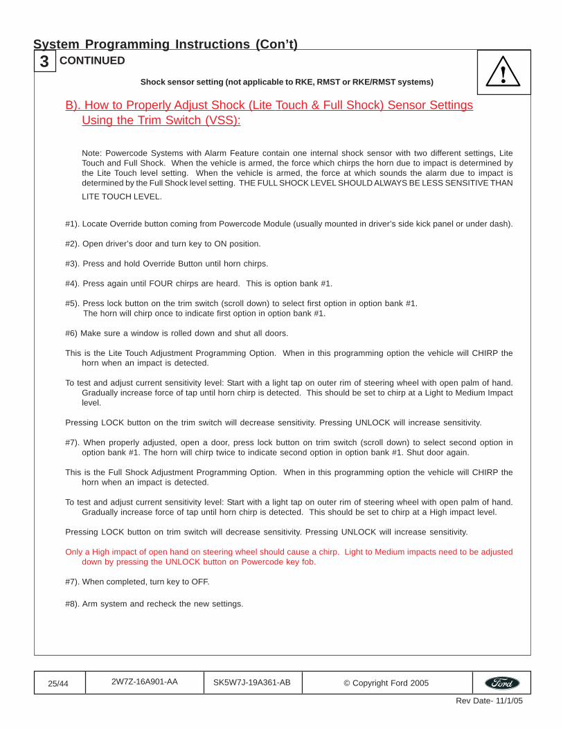
Shock sensor setting (not applicable to RKE, RMST or RKE/RMST systems)
B). How to Properly Adjust Shock (Lite Touch & Full Shock) Sensor SettingsUsing the Trim Switch (VSS):
Note: Powercode Systems with Alarm Feature contain one internal shock sensor with two different settings, LiteTouch and Full Shock. When the vehicle is armed, the force which chirps the horn due to impact is determined bythe Lite Touch level setting. When the vehicle is armed, the force at which sounds the alarm due to impact isdetermined by the Full Shock level setting. THE FULL SHOCK LEVEL SHOULD ALWAYS BE LESS SENSITIVE THANLITE TOUCH LEVEL.
#1). Locate Override button coming from Powercode Module (usually mounted in driver’s side kick panel or under dash).
#2). Open driver’s door and turn key to ON position.
#3). Press and hold Override Button until horn chirps.
#4). Press again until FOUR chirps are heard. This is option bank #1.
#5). Press lock button on the trim switch (scroll down) to select first option in option bank #1. The horn will chirp once to indicate first option in option bank #1.
#6) Make sure a window is rolled down and shut all doors.
This is the Lite Touch Adjustment Programming Option. When in this programming option the vehicle will CHIRP thehorn when an impact is detected.
To test and adjust current sensitivity level: Start with a light tap on outer rim of steering wheel with open palm of hand.Gradually increase force of tap until horn chirp is detected. This should be set to chirp at a Light to Medium Impactlevel.
Pressing LOCK button on the trim switch will decrease sensitivity. Pressing UNLOCK will increase sensitivity.
#7). When properly adjusted, open a door, press lock button on trim switch (scroll down) to select second option inoption bank #1. The horn will chirp twice to indicate second option in option bank #1. Shut door again.
This is the Full Shock Adjustment Programming Option. When in this programming option the vehicle will CHIRP thehorn when an impact is detected.
To test and adjust current sensitivity level: Start with a light tap on outer rim of steering wheel with open palm of hand.Gradually increase force of tap until horn chirp is detected. This should be set to chirp at a High impact level.
Pressing LOCK button on trim switch will decrease sensitivity. Pressing UNLOCK will increase sensitivity.
Only a High impact of open hand on steering wheel should cause a chirp. Light to Medium impacts need to be adjusteddown by pressing the UNLOCK button on Powercode key fob.
#7). When completed, turn key to OFF.
#8). Arm system and recheck the new settings.
3 CONTINUEDSystem Programming Instructions (Con’t)
26/44 SK5W7J-19A361-AB © Copyright Ford 20052W7Z-16A901-AA
Rev Date- 11/1/05
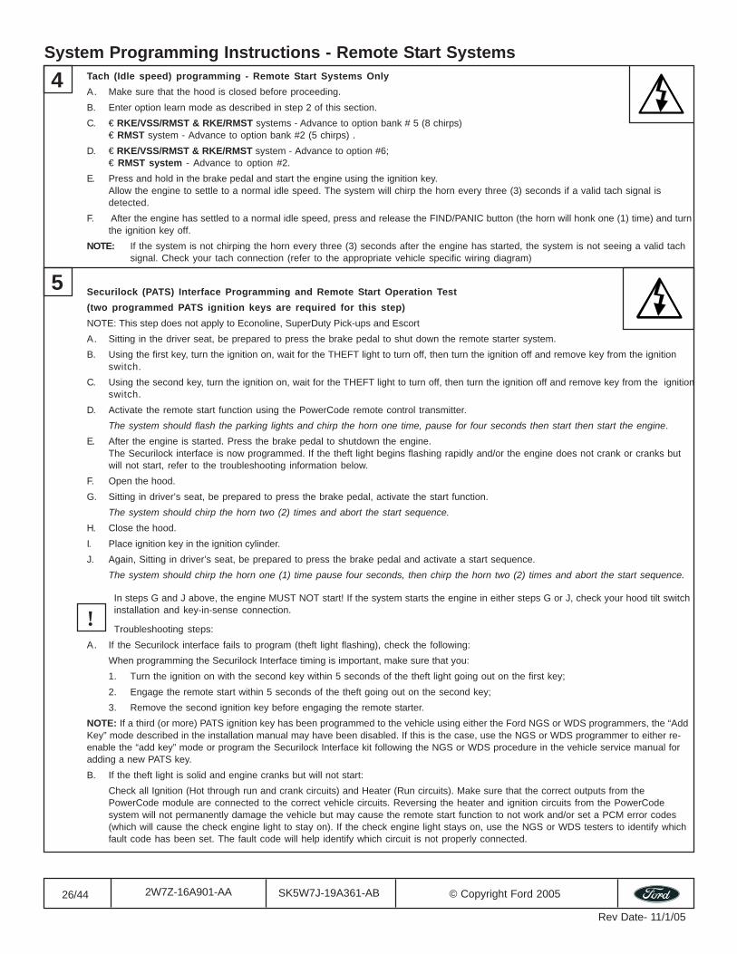
Securilock (PATS) Interface Programming and Remote Start Operation Test(two programmed PATS ignition keys are required for this step)NOTE: This step does not apply to Econoline, SuperDuty Pick-ups and EscortA. Sitting in the driver seat, be prepared to press the brake pedal to shut down the remote starter system.B. Using the first key, turn the ignition on, wait for the THEFT light to turn off, then turn the ignition off and remove key from the ignition
switch.C. Using the second key, turn the ignition on, wait for the THEFT light to turn off, then turn the ignition off and remove key from the ignition
switch.D. Activate the remote start function using the PowerCode remote control transmitter.
The system should flash the parking lights and chirp the horn one time, pause for four seconds then start then start the engine.E. After the engine is started. Press the brake pedal to shutdown the engine.
The Securilock interface is now programmed. If the theft light begins flashing rapidly and/or the engine does not crank or cranks butwill not start, refer to the troubleshooting information below.
F. Open the hood.G. Sitting in driver’s seat, be prepared to press the brake pedal, activate the start function.
The system should chirp the horn two (2) times and abort the start sequence.
H. Close the hood.I. Place ignition key in the ignition cylinder.J. Again, Sitting in driver’s seat, be prepared to press the brake pedal and activate a start sequence.
The system should chirp the horn one (1) time pause four seconds, then chirp the horn two (2) times and abort the start sequence.
In steps G and J above, the engine MUST NOT start! If the system starts the engine in either steps G or J, check your hood tilt switchinstallation and key-in-sense connection.
Troubleshooting steps:A. If the Securilock interface fails to program (theft light flashing), check the following:
When programming the Securilock Interface timing is important, make sure that you:1. Turn the ignition on with the second key within 5 seconds of the theft light going out on the first key;2. Engage the remote start within 5 seconds of the theft going out on the second key;3. Remove the second ignition key before engaging the remote starter.
NOTE: If a third (or more) PATS ignition key has been programmed to the vehicle using either the Ford NGS or WDS programmers, the “AddKey” mode described in the installation manual may have been disabled. If this is the case, use the NGS or WDS programmer to either re-enable the “add key” mode or program the Securilock Interface kit following the NGS or WDS procedure in the vehicle service manual foradding a new PATS key.B. If the theft light is solid and engine cranks but will not start:
Check all Ignition (Hot through run and crank circuits) and Heater (Run circuits). Make sure that the correct outputs from thePowerCode module are connected to the correct vehicle circuits. Reversing the heater and ignition circuits from the PowerCodesystem will not permanently damage the vehicle but may cause the remote start function to not work and/or set a PCM error codes(which will cause the check engine light to stay on). If the check engine light stays on, use the NGS or WDS testers to identify whichfault code has been set. The fault code will help identify which circuit is not properly connected.
5
!
4 Tach (Idle speed) programming - Remote Start Systems OnlyA. Make sure that the hood is closed before proceeding.B. Enter option learn mode as described in step 2 of this section.C. € RKE/VSS/RMST & RKE/RMST systems - Advance to option bank # 5 (8 chirps)
€ RMST system - Advance to option bank #2 (5 chirps) .D. € RKE/VSS/RMST & RKE/RMST system - Advance to option #6;
€ RMST system - Advance to option #2.E. Press and hold in the brake pedal and start the engine using the ignition key.
Allow the engine to settle to a normal idle speed. The system will chirp the horn every three (3) seconds if a valid tach signal isdetected.
F. After the engine has settled to a normal idle speed, press and release the FIND/PANIC button (the horn will honk one (1) time) and turnthe ignition key off.
NOTE: If the system is not chirping the horn every three (3) seconds after the engine has started, the system is not seeing a valid tachsignal. Check your tach connection (refer to the appropriate vehicle specific wiring diagram)
System Programming Instructions - Remote Start Systems
27/44 SK5W7J-19A361-AB © Copyright Ford 20052W7Z-16A901-AA
Rev Date- 11/1/05
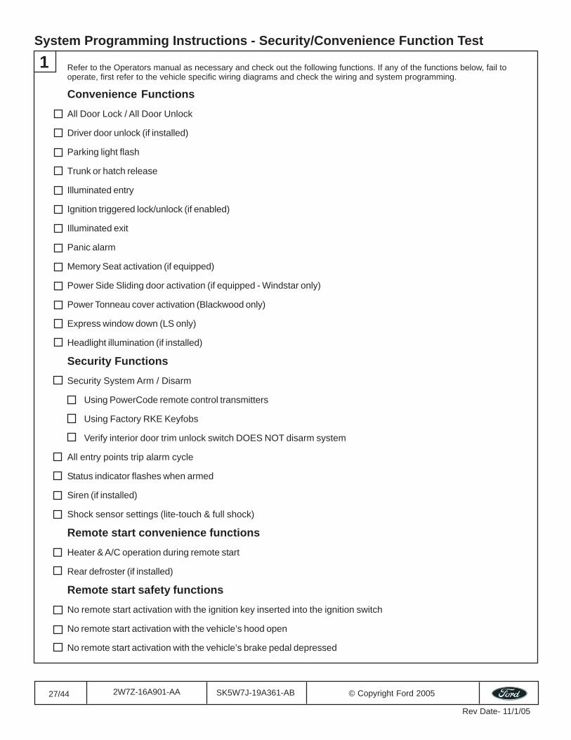
System Programming Instructions - Security/Convenience Function Test
Convenience FunctionsAll Door Lock / All Door Unlock
Driver door unlock (if installed)
Parking light flash
Trunk or hatch release
Illuminated entry
Ignition triggered lock/unlock (if enabled)
Illuminated exit
Panic alarm
Memory Seat activation (if equipped)
Power Side Sliding door activation (if equipped - Windstar only)
Power Tonneau cover activation (Blackwood only)
Express window down (LS only)
Headlight illumination (if installed)
Security FunctionsSecurity System Arm / Disarm
Using PowerCode remote control transmitters
Using Factory RKE Keyfobs
Verify interior door trim unlock switch DOES NOT disarm system
All entry points trip alarm cycle
Status indicator flashes when armed
Siren (if installed)
Shock sensor settings (lite-touch & full shock)
Remote start convenience functionsHeater & A/C operation during remote start
Rear defroster (if installed)
Remote start safety functionsNo remote start activation with the ignition key inserted into the ignition switch
No remote start activation with the vehicle’s hood open
No remote start activation with the vehicle’s brake pedal depressed
Refer to the Operators manual as necessary and check out the following functions. If any of the functions below, fail tooperate, first refer to the vehicle specific wiring diagrams and check the wiring and system programming.
1
28/44 SK5W7J-19A361-AB © Copyright Ford 20052W7Z-16A901-AA
Rev Date- 11/1/05
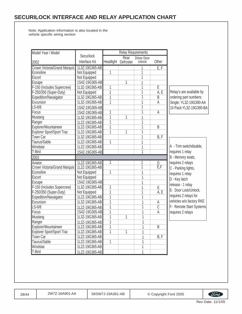
SECURILOCK INTERFACE AND RELAY APPLICATION CHART
Note: Application information is also located in thevehicle specific wiring section
Model Year / Model Relay Requirements
2002
Securilock Interface Kit Headlight
Rear Defroster
Driver Door Unlock Other
Crown Victoria/Grand Marquis 1L3Z-19G365-ABEconoline Not Equipped 1Escort Not EquippedEscape 1S4Z-19G365-AB 1F-150 (Includes Supercrew) 1L3Z-19G365-AB 1F-250/350 (Super-Duty) Not Equipped 1 A, EExpedition/Navaigator 1L3Z-19G365-AB 1 BExcursion 1L3Z-19G365-AB 1 ALS-6/8 1S4Z-19G365-ABFocus 1S4Z-19G365-AB 1 AMustang 1L3Z-19G365-AB 1 1 1Ranger 1L2Z-19G365-AB 1Explorer/Mountaineer 1L2Z-19G365-AB 1 BExplorer Sport/Sport Trac 1L2Z-19G365-AB 1 1Town Car 1L3Z-19G365-AB 1 B, FTaurus/Sable 1L2Z-19G365-AB 1Windstar 1L2Z-19G365-ABT-Bird 1S4Z-19G365-AB2003Aviator 1L2Z-19G365-AB 1 DCrown Victoria/Grand Marquis 1L2Z-19G365-AB 1� E,FEconoline Not Equipped 1Escort Not EquippedEscape 1S4Z-19G365-ABF-150 (Includes Supercrew) 1L3Z-19G365-AB 1F-250/350 (Super-Duty) Not Equipped 1 A, EExpedition/Navaigator 1L2Z-19G365-AB 1Excursion 1L3Z-19G365-AB 1 ALS-6/8 1L2Z-19G365-AB 1 CFocus 1S4Z-19G365-AB 1 AMustang 1L3Z-19G365-AB 1 1 1Ranger 1L2Z-19G365-AB 1Explorer/Mountaineer 1L2Z-19G365-AB 1 BExplorer Sport/Sport Trac 1L2Z-19G365-AB 1 1Town Car 1L2Z-19G365-AB 1 B, FTaurus/Sable 1L2Z-19G365-AB 1Windstar 1L2Z-19G365-ABT-Bird 1L2Z-19G365-AB
111
11111
111
111
111
11111
111
111
Relay’s are available by ordering part numbers:Single: YL3Z-19G390-AA10 Pack:YL3Z-19G390-BA
A - Trim switchdisable,requires 1 relayB - Memory seats, requires 2 relaysC - Parking lights, requires 1 relayD - Key latch release - 1 relayE- Door Lock/Unlock, requires 2 relays for vehicles w/o factory RKEF- Remote Start Systemsrequires 2 relays
1� E
1� E, F
1
1� E
29/44 SK5W7J-19A361-AB © Copyright Ford 20052W7Z-16A901-AA
Rev Date- 11/1/05
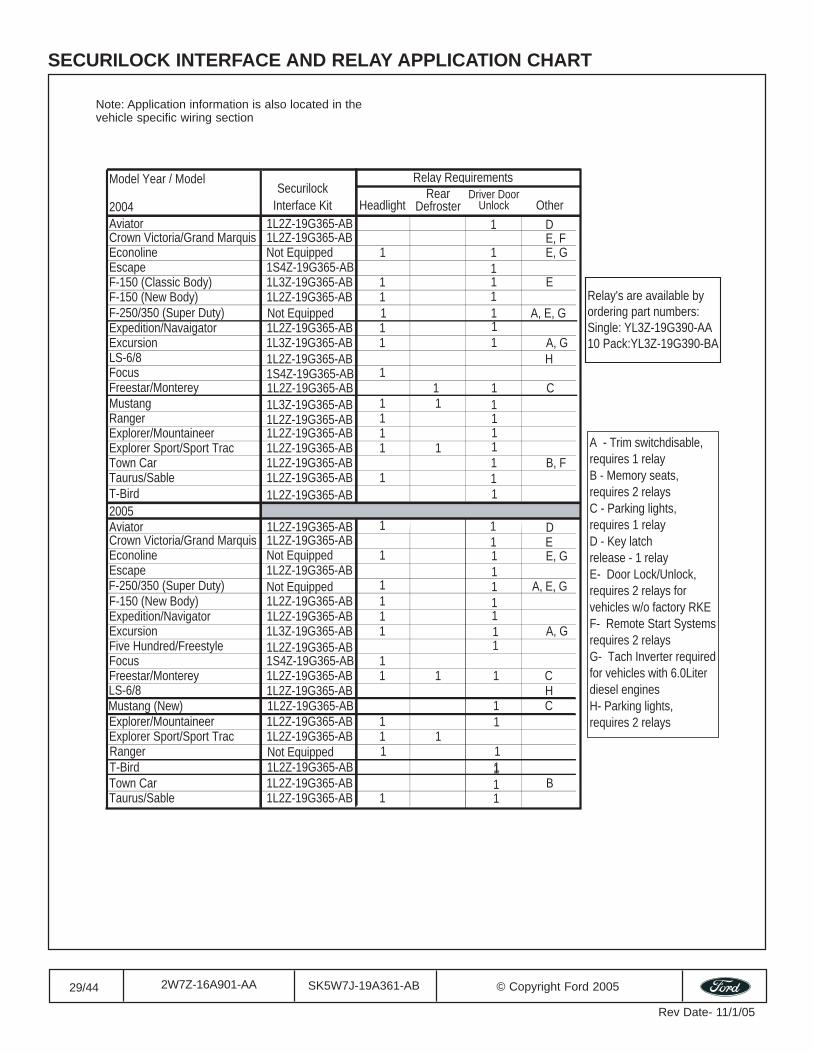
SECURILOCK INTERFACE AND RELAY APPLICATION CHART
Note: Application information is also located in thevehicle specific wiring section
Model Year / Model Relay Requirements
2004
Securilock Interface Kit Headlight
Rear Defroster
Driver Door Unlock Other
Aviator 1L2Z-19G365-ABCrown Victoria/Grand Marquis 1L2Z-19G365-ABEconoline Not Equipped 1Escape 1S4Z-19G365-ABF-150 (Classic Body) 1L3Z-19G365-AB 1F-150 (New Body) 1L2Z-19G365-AB 1
Expedition/Navaigator 1L2Z-19G365-AB 1Excursion 1L3Z-19G365-AB 1 A, GLS-6/8 1L2Z-19G365-AB H Focus 1S4Z-19G365-AB 1
Mustang 1L3Z-19G365-AB 1 1 1Ranger 1L2Z-19G365-AB 1Explorer/Mountaineer 1L2Z-19G365-AB 1Explorer Sport/Sport Trac 1L2Z-19G365-AB 1 1Town Car 1L2Z-19G365-AB 1 B, FTaurus/Sable 1L2Z-19G365-AB 1T-Bird 1L2Z-19G365-AB2005Aviator 1L2Z-19G365-AB 1 DCrown Victoria/Grand Marquis 1L2Z-19G365-AB 1 EEconoline Not Equipped 1Escape 1L2Z-19G365-AB
F-150 (New Body) 1L2Z-19G365-AB 1Expedition/Navigator 1L2Z-19G365-AB 1Excursion 1L3Z-19G365-AB 1 A, GFive Hundred/Freestyle 1L2Z-19G365-ABFocus 1S4Z-19G365-AB 1 Freestar/Monterey 1L2Z-19G365-AB 1 1 1 C
Explorer/Mountaineer 1L2Z-19G365-AB 1Explorer Sport/Sport Trac 1L2Z-19G365-AB 1 1
Town Car 1L2Z-19G365-AB 1 BTaurus/Sable 1L2Z-19G365-AB 1
E, F1 E, G1
1
11
111
11
11
111
1
1
1
Relay's are available by ordering part numbers:Single: YL3Z-19G390-AA10 Pack:YL3Z-19G390-BA
A - Trim switchdisable,requires 1 relayB - Memory seats, requires 2 relaysC - Parking lights, requires 1 relayD - Key latch release - 1 relayE- Door Lock/Unlock, requires 2 relays for vehicles w/o factory RKEF- Remote Start Systemsrequires 2 relaysG- Tach Inverter requiredfor vehicles with 6.0Literdiesel enginesH- Parking lights,requires 2 relays
1 E
1 D
1
1
F-250/350 (Super Duty) Not Equipped 1 1 A, E, G
Freestar/Monterey 1L2Z-19G365-AB 1 1 C
LS-6/8 1L2Z-19G365-AB H Mustang (New) 1 C 1L2Z-19G365-AB
T-Bird 1L2Z-19G365-AB 1
F-250/350 (Super Duty) Not Equipped 1 1 A, E, G
E, G
Ranger Not Equipped 1 1

31/44 SK5W7J-19A361-AB © Copyright Ford 20052W7Z-16A901-AA
Rev Date- 11/1/05
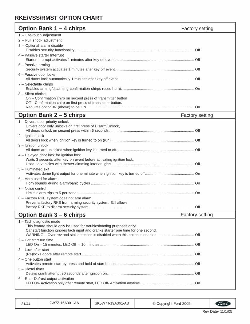
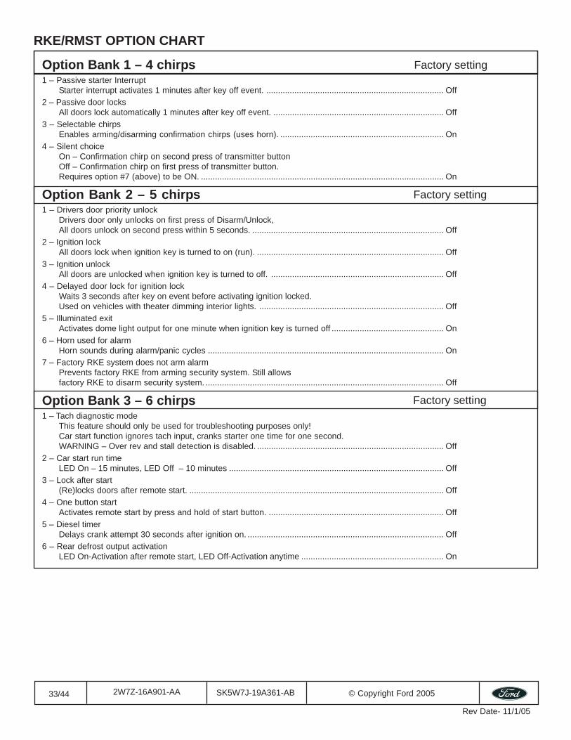
Option Bank 1 – 4 chirps1 – Lite-touch adjustment2 – Full shock adjustment3 – Optional alarm disable
Disables security functionality. .................................................................................................................... Off4 – Passive starter Interrupt
Starter interrupt activates 1 minutes after key off event. ............................................................................ Off5 – Passive arming
Security system activates 1 minutes after key off event. ............................................................................ Off6 – Passive door locks
All doors lock automatically 1 minutes after key off event. ......................................................................... Off7 – Selectable chirps
Enables arming/disarming confirmation chirps (uses horn). ...................................................................... On8 – Silent choice
On – Confirmation chirp on second press of transmitter buttonOff – Confirmation chirp on first press of transmitter button.Requires option #7 (above) to be ON. ........................................................................................................ On
Option Bank 2 – 5 chirps1 – Drivers door priority unlock
Drivers door only unlocks on first press of Disarm/Unlock,All doors unlock on second press within 5 seconds. .................................................................................. Off
2 – Ignition lockAll doors lock when ignition key is turned to on (run). ................................................................................ Off
3 – Ignition unlockAll doors are unlocked when ignition key is turned to off. .......................................................................... Off
4 – Delayed door lock for ignition lockWaits 3 seconds after key on event before activating ignition lock.Used on vehicles with theater dimming interior lights. ............................................................................... Off
5 – Illuminated exitActivates dome light output for one minute when ignition key is turned off ................................................ On
6 – Horn used for alarmHorn sounds during alarm/panic cycles ..................................................................................................... On
7 – Noise controlLimits alarm trips to 5 per zone .................................................................................................................. On
8 – Factory RKE system does not arm alarmPrevents factory RKE from arming security system. Still allowsfactory RKE to disarm security system. ...................................................................................................... Off
Option Bank 3 – 6 chirps1 – Tach diagnostic mode
This feature should only be used for troubleshooting purposes only!Car start function ignores tach input and cranks starter one time for one second.WARNING – Over rev and stall detection is disabled when this option is enabled. ................................... Off
2 – Car start run timeLED On – 15 minutes, LED Off – 10 minutes ............................................................................................ Off
3 – Lock after start(Re)locks doors after remote start. ............................................................................................................. Off
4 – One button startActivates remote start by press and hold of start button. ........................................................................... Off
5 – Diesel timerDelays crank attempt 30 seconds after ignition on. .................................................................................... Off
6 – Rear Defrost output activationLED On- Activation only after remote start, LED Off- Activation anytime .................................................... On
RKE/VSS/RMST OPTION CHART
Factory setting
Factory setting
Factory setting
32/44 SK5W7J-19A361-AB © Copyright Ford 20052W7Z-16A901-AA
Rev Date- 11/1/05
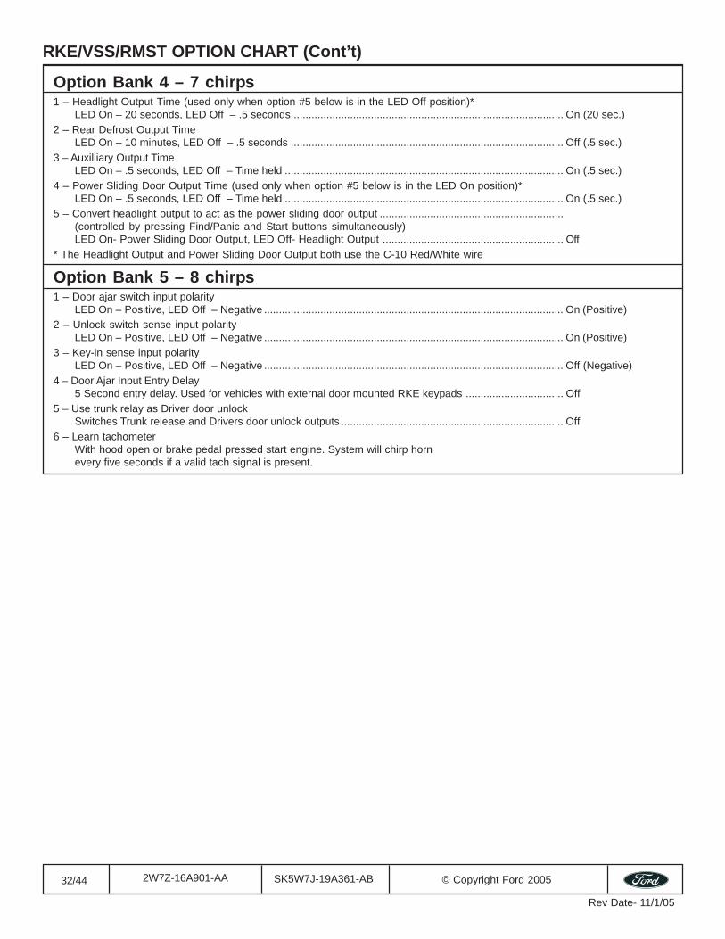
Option Bank 4 – 7 chirps1 – Headlight Output Time (used only when option #5 below is in the LED Off position)*
LED On – 20 seconds, LED Off – .5 seconds ........................................................................................... On (20 sec.)2 – Rear Defrost Output Time
LED On – 10 minutes, LED Off – .5 seconds ............................................................................................ Off (.5 sec.)3 – Auxilliary Output Time
LED On – .5 seconds, LED Off – Time held .............................................................................................. On (.5 sec.)4 – Power Sliding Door Output Time (used only when option #5 below is in the LED On position)*
LED On – .5 seconds, LED Off – Time held .............................................................................................. On (.5 sec.)5 – Convert headlight output to act as the power sliding door output ..............................................................
(controlled by pressing Find/Panic and Start buttons simultaneously)LED On- Power Sliding Door Output, LED Off- Headlight Output ............................................................. Off
* The Headlight Output and Power Sliding Door Output both use the C-10 Red/White wire
Option Bank 5 – 8 chirps1 – Door ajar switch input polarity
LED On – Positive, LED Off – Negative ..................................................................................................... On (Positive)2 – Unlock switch sense input polarity
LED On – Positive, LED Off – Negative ..................................................................................................... On (Positive)3 – Key-in sense input polarity
LED On – Positive, LED Off – Negative ..................................................................................................... Off (Negative)4 – Door Ajar Input Entry Delay
5 Second entry delay. Used for vehicles with external door mounted RKE keypads ................................. Off5 – Use trunk relay as Driver door unlock
Switches Trunk release and Drivers door unlock outputs ........................................................................... Off6 – Learn tachometer
With hood open or brake pedal pressed start engine. System will chirp hornevery five seconds if a valid tach signal is present.
RKE/VSS/RMST OPTION CHART (Cont’t)
33/44 SK5W7J-19A361-AB © Copyright Ford 20052W7Z-16A901-AA
Rev Date- 11/1/05
Option Bank 1 – 4 chirps1 – Passive starter Interrupt
Starter interrupt activates 1 minutes after key off event. ............................................................................ Off2 – Passive door locks
All doors lock automatically 1 minutes after key off event. ......................................................................... Off3 – Selectable chirps
Enables arming/disarming confirmation chirps (uses horn). ...................................................................... On4 – Silent choice
On – Confirmation chirp on second press of transmitter buttonOff – Confirmation chirp on first press of transmitter button.Requires option #7 (above) to be ON. ........................................................................................................ On
Option Bank 2 – 5 chirps1 – Drivers door priority unlock
Drivers door only unlocks on first press of Disarm/Unlock,All doors unlock on second press within 5 seconds. .................................................................................. Off
2 – Ignition lockAll doors lock when ignition key is turned to on (run). ................................................................................ Off
3 – Ignition unlockAll doors are unlocked when ignition key is turned to off. .......................................................................... Off
4 – Delayed door lock for ignition lockWaits 3 seconds after key on event before activating ignition locked.Used on vehicles with theater dimming interior lights. ............................................................................... Off
5 – Illuminated exitActivates dome light output for one minute when ignition key is turned off ................................................ On
6 – Horn used for alarmHorn sounds during alarm/panic cycles ..................................................................................................... On
7 – Factory RKE system does not arm alarmPrevents factory RKE from arming security system. Still allowsfactory RKE to disarm security system. ...................................................................................................... Off
Option Bank 3 – 6 chirps1 – Tach diagnostic mode
This feature should only be used for troubleshooting purposes only!Car start function ignores tach input, cranks starter one time for one second.WARNING – Over rev and stall detection is disabled. ................................................................................ Off
2 – Car start run timeLED On – 15 minutes, LED Off – 10 minutes ............................................................................................ Off
3 – Lock after start(Re)locks doors after remote start. ............................................................................................................. Off
4 – One button startActivates remote start by press and hold of start button. ........................................................................... Off
5 – Diesel timerDelays crank attempt 30 seconds after ignition on. .................................................................................... Off
6 – Rear defrost output activationLED On-Activation after remote start, LED Off-Activation anytime ............................................................. On
RKE/RMST OPTION CHART
Factory setting
Factory setting
Factory setting
34/44 SK5W7J-19A361-AB © Copyright Ford 20052W7Z-16A901-AA
Rev Date- 11/1/05
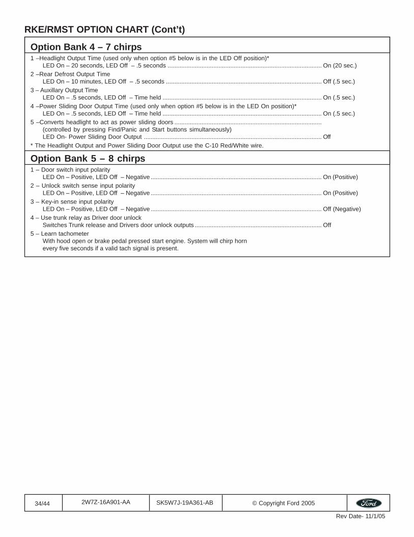
Option Bank 4 – 7 chirps1 –Headlight Output Time (used only when option #5 below is in the LED Off position)*
LED On – 20 seconds, LED Off – .5 seconds ........................................................................................... On (20 sec.)2 –Rear Defrost Output Time
LED On – 10 minutes, LED Off – .5 seconds ............................................................................................ Off (.5 sec.)3 – Auxillary Output Time
LED On – .5 seconds, LED Off – Time held .............................................................................................. On (.5 sec.)4 –Power Sliding Door Output Time (used only when option #5 below is in the LED On position)*
LED On – .5 seconds, LED Off – Time held .............................................................................................. On (.5 sec.)5 –Converts headlight to act as power sliding doors .......................................................................................
(controlled by pressing Find/Panic and Start buttons simultaneously)LED On- Power Sliding Door Output ......................................................................................................... Off
* The Headlight Output and Power Sliding Door Output use the C-10 Red/White wire.
Option Bank 5 – 8 chirps1 – Door switch input polarity
LED On – Positive, LED Off – Negative ..................................................................................................... On (Positive)2 – Unlock switch sense input polarity
LED On – Positive, LED Off – Negative ..................................................................................................... On (Positive)3 – Key-in sense input polarity
LED On – Positive, LED Off – Negative ..................................................................................................... Off (Negative)4 – Use trunk relay as Driver door unlock
Switches Trunk release and Drivers door unlock outputs ........................................................................... Off5 – Learn tachometer
With hood open or brake pedal pressed start engine. System will chirp hornevery five seconds if a valid tach signal is present.
RKE/RMST OPTION CHART (Cont’t)
35/44 SK5W7J-19A361-AB © Copyright Ford 20052W7Z-16A901-AA
Rev Date- 11/1/05
RMST OPTION CHART
Factory setting
Factory setting
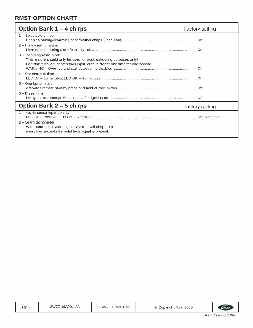
Option Bank 1 – 4 chirps1 – Selectable chirps
Enables arming/disarming confirmation chirps (uses horn). ...................................................................... On2 – Horn used for alarm
Horn sounds during alarm/panic cycles ..................................................................................................... On3 – Tach diagnostic mode
This feature should only be used for troubleshooting purposes only!Car start function ignores tach input, cranks starter one time for one second.WARNING – Over rev and stall detection is disabled. ................................................................................ Off
4 – Car start run timeLED On – 15 minutes, LED Off – 10 minutes ............................................................................................ Off
5 – One button startActivates remote start by press and hold of start button. ........................................................................... Off
6 – Diesel timerDelays crank attempt 30 seconds after ignition on. .................................................................................... Off
Option Bank 2 – 5 chirps1 – Key-in sense input polarity
LED On – Positive, LED Off – Negative ..................................................................................................... Off (Negative)2 – Learn tachometer
With hood open start engine. System will chirp hornevery five seconds if a valid tach signal is present.
36/44 SK5W7J-19A361-AB © Copyright Ford 20052W7Z-16A901-AA
Rev Date- 11/1/05
Deluxe RKE/VSS OPTION CHARTFactory setting
Factory setting
Factory setting
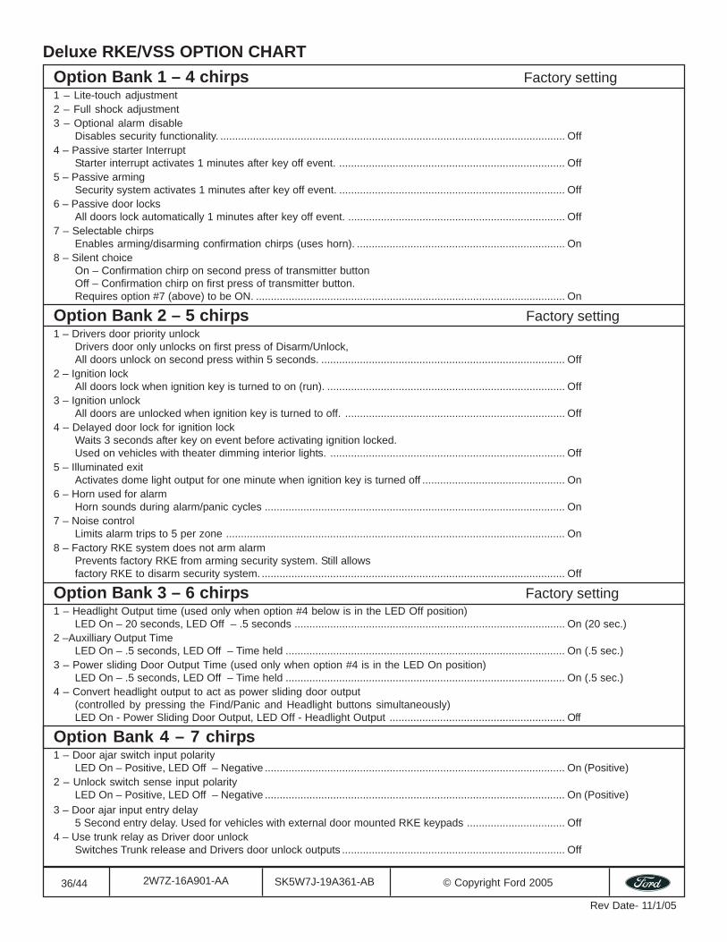
Option Bank 1 – 4 chirps1 – Lite-touch adjustment2 – Full shock adjustment3 – Optional alarm disable
Disables security functionality. .................................................................................................................... Off4 – Passive starter Interrupt
Starter interrupt activates 1 minutes after key off event. ............................................................................ Off5 – Passive arming
Security system activates 1 minutes after key off event. ............................................................................ Off6 – Passive door locks
All doors lock automatically 1 minutes after key off event. ......................................................................... Off7 – Selectable chirps
Enables arming/disarming confirmation chirps (uses horn). ...................................................................... On8 – Silent choice
On – Confirmation chirp on second press of transmitter buttonOff – Confirmation chirp on first press of transmitter button.Requires option #7 (above) to be ON. ........................................................................................................ On
Option Bank 2 – 5 chirps1 – Drivers door priority unlock
Drivers door only unlocks on first press of Disarm/Unlock,All doors unlock on second press within 5 seconds. .................................................................................. Off
2 – Ignition lockAll doors lock when ignition key is turned to on (run). ................................................................................ Off
3 – Ignition unlockAll doors are unlocked when ignition key is turned to off. .......................................................................... Off
4 – Delayed door lock for ignition lockWaits 3 seconds after key on event before activating ignition locked.Used on vehicles with theater dimming interior lights. ............................................................................... Off
5 – Illuminated exitActivates dome light output for one minute when ignition key is turned off ................................................ On
6 – Horn used for alarmHorn sounds during alarm/panic cycles ..................................................................................................... On
7 – Noise controlLimits alarm trips to 5 per zone .................................................................................................................. On
8 – Factory RKE system does not arm alarmPrevents factory RKE from arming security system. Still allowsfactory RKE to disarm security system. ...................................................................................................... Off
Option Bank 3 – 6 chirps1 – Headlight Output time (used only when option #4 below is in the LED Off position)
LED On – 20 seconds, LED Off – .5 seconds ........................................................................................... On (20 sec.)2 –Auxilliary Output Time
LED On – .5 seconds, LED Off – Time held .............................................................................................. On (.5 sec.)3 – Power sliding Door Output Time (used only when option #4 is in the LED On position)
LED On – .5 seconds, LED Off – Time held .............................................................................................. On (.5 sec.)4 – Convert headlight output to act as power sliding door output
(controlled by pressing the Find/Panic and Headlight buttons simultaneously)LED On - Power Sliding Door Output, LED Off - Headlight Output ........................................................... Off
Option Bank 4 – 7 chirps1 – Door ajar switch input polarity
LED On – Positive, LED Off – Negative ..................................................................................................... On (Positive)2 – Unlock switch sense input polarity
LED On – Positive, LED Off – Negative ..................................................................................................... On (Positive)3 – Door ajar input entry delay
5 Second entry delay. Used for vehicles with external door mounted RKE keypads ................................. Off4 – Use trunk relay as Driver door unlock
Switches Trunk release and Drivers door unlock outputs ........................................................................... Off
37/44 SK5W7J-19A361-AB © Copyright Ford 20052W7Z-16A901-AA
Rev Date- 11/1/05
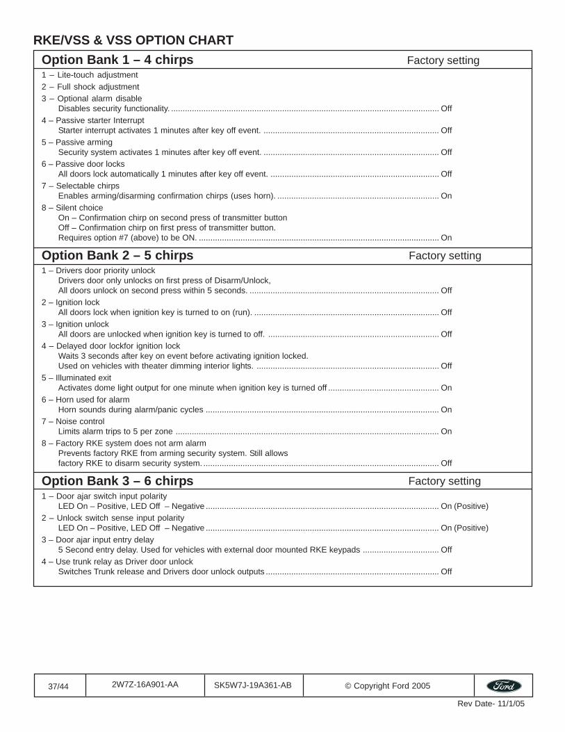
RKE/VSS & VSS OPTION CHARTFactory setting
Factory setting
Factory setting
Option Bank 1 – 4 chirps1 – Lite-touch adjustment2 – Full shock adjustment3 – Optional alarm disable
Disables security functionality. .................................................................................................................... Off4 – Passive starter Interrupt
Starter interrupt activates 1 minutes after key off event. ............................................................................ Off5 – Passive arming
Security system activates 1 minutes after key off event. ............................................................................ Off6 – Passive door locks
All doors lock automatically 1 minutes after key off event. ......................................................................... Off7 – Selectable chirps
Enables arming/disarming confirmation chirps (uses horn). ...................................................................... On8 – Silent choice
On – Confirmation chirp on second press of transmitter buttonOff – Confirmation chirp on first press of transmitter button.Requires option #7 (above) to be ON. ........................................................................................................ On
Option Bank 2 – 5 chirps1 – Drivers door priority unlock
Drivers door only unlocks on first press of Disarm/Unlock,All doors unlock on second press within 5 seconds. .................................................................................. Off
2 – Ignition lockAll doors lock when ignition key is turned to on (run). ................................................................................ Off
3 – Ignition unlockAll doors are unlocked when ignition key is turned to off. .......................................................................... Off
4 – Delayed door lockfor ignition lockWaits 3 seconds after key on event before activating ignition locked.Used on vehicles with theater dimming interior lights. ............................................................................... Off
5 – Illuminated exitActivates dome light output for one minute when ignition key is turned off ................................................ On
6 – Horn used for alarmHorn sounds during alarm/panic cycles ..................................................................................................... On
7 – Noise controlLimits alarm trips to 5 per zone .................................................................................................................. On
8 – Factory RKE system does not arm alarmPrevents factory RKE from arming security system. Still allowsfactory RKE to disarm security system. ...................................................................................................... Off
Option Bank 3 – 6 chirps1 – Door ajar switch input polarity
LED On – Positive, LED Off – Negative ..................................................................................................... On (Positive)2 – Unlock switch sense input polarity
LED On – Positive, LED Off – Negative ..................................................................................................... On (Positive)3 – Door ajar input entry delay
5 Second entry delay. Used for vehicles with external door mounted RKE keypads ................................. Off4 – Use trunk relay as Driver door unlock
Switches Trunk release and Drivers door unlock outputs ........................................................................... Off
38/44 SK5W7J-19A361-AB © Copyright Ford 20052W7Z-16A901-AA
Rev Date- 11/1/05
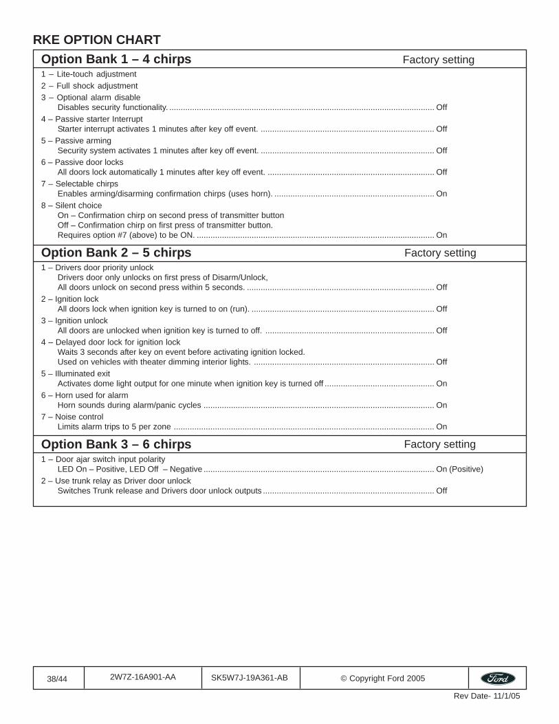
RKE OPTION CHARTFactory setting
Factory setting
Factory setting
Option Bank 1 – 4 chirps1 – Lite-touch adjustment2 – Full shock adjustment3 – Optional alarm disable
Disables security functionality. .................................................................................................................... Off4 – Passive starter Interrupt
Starter interrupt activates 1 minutes after key off event. ............................................................................ Off5 – Passive arming
Security system activates 1 minutes after key off event. ............................................................................ Off6 – Passive door locks
All doors lock automatically 1 minutes after key off event. ......................................................................... Off7 – Selectable chirps
Enables arming/disarming confirmation chirps (uses horn). ...................................................................... On8 – Silent choice
On – Confirmation chirp on second press of transmitter buttonOff – Confirmation chirp on first press of transmitter button.Requires option #7 (above) to be ON. ........................................................................................................ On
Option Bank 2 – 5 chirps1 – Drivers door priority unlock
Drivers door only unlocks on first press of Disarm/Unlock,All doors unlock on second press within 5 seconds. .................................................................................. Off
2 – Ignition lockAll doors lock when ignition key is turned to on (run). ................................................................................ Off
3 – Ignition unlockAll doors are unlocked when ignition key is turned to off. .......................................................................... Off
4 – Delayed door lock for ignition lockWaits 3 seconds after key on event before activating ignition locked.Used on vehicles with theater dimming interior lights. ............................................................................... Off
5 – Illuminated exitActivates dome light output for one minute when ignition key is turned off ................................................ On
6 – Horn used for alarmHorn sounds during alarm/panic cycles ..................................................................................................... On
7 – Noise controlLimits alarm trips to 5 per zone .................................................................................................................. On
Option Bank 3 – 6 chirps1 – Door ajar switch input polarity
LED On – Positive, LED Off – Negative ..................................................................................................... On (Positive)2 – Use trunk relay as Driver door unlock
Switches Trunk release and Drivers door unlock outputs ........................................................................... Off
39/44 SK5W7J-19A361-AB © Copyright Ford 20052W7Z-16A901-AA
Rev Date- 11/1/05
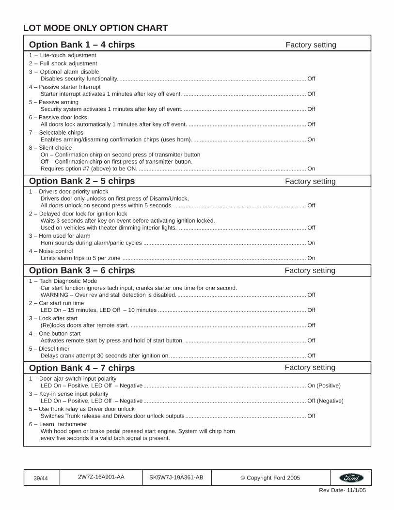
Option Bank 1 – 4 chirps1 – Lite-touch adjustment2 – Full shock adjustment3 – Optional alarm disable
Disables security functionality. .................................................................................................................... Off4 – Passive starter Interrupt
Starter interrupt activates 1 minutes after key off event. ............................................................................ Off5 – Passive arming
Security system activates 1 minutes after key off event. ............................................................................ Off6 – Passive door locks
All doors lock automatically 1 minutes after key off event. ......................................................................... Off7 – Selectable chirps
Enables arming/disarming confirmation chirps (uses horn). ...................................................................... On8 – Silent choice
On – Confirmation chirp on second press of transmitter buttonOff – Confirmation chirp on first press of transmitter button.Requires option #7 (above) to be ON. ........................................................................................................ On
Option Bank 2 – 5 chirps1 – Drivers door priority unlock
Drivers door only unlocks on first press of Disarm/Unlock,All doors unlock on second press within 5 seconds. .................................................................................. Off
2 – Delayed door lock for ignition lockWaits 3 seconds after key on event before activating ignition locked.Used on vehicles with theater dimming interior lights. ............................................................................... Off
3 – Horn used for alarmHorn sounds during alarm/panic cycles ..................................................................................................... On
4 – Noise controlLimits alarm trips to 5 per zone .................................................................................................................. On
Option Bank 3 – 6 chirps1 – Tach Diagnostic Mode
Car start function ignores tach input, cranks starter one time for one second.WARNING – Over rev and stall detection is disabled. ................................................................................ Off
2 – Car start run timeLED On – 15 minutes, LED Off – 10 minutes ............................................................................................ Off
3 – Lock after start(Re)locks doors after remote start. ............................................................................................................. Off
4 – One button startActivates remote start by press and hold of start button. ........................................................................... Off
5 – Diesel timerDelays crank attempt 30 seconds after ignition on. .................................................................................... Off
Option Bank 4 – 7 chirps1 – Door ajar switch input polarity
LED On – Positive, LED Off – Negative ..................................................................................................... On (Positive)3 – Key-in sense input polarity
LED On – Positive, LED Off – Negative ..................................................................................................... Off (Negative)5 – Use trunk relay as Driver door unlock
Switches Trunk release and Drivers door unlock outputs ........................................................................... Off6 – Learn tachometer
With hood open or brake pedal pressed start engine. System will chirp hornevery five seconds if a valid tach signal is present.
LOT MODE ONLY OPTION CHART
Factory setting
Factory setting
Factory setting
Factory setting
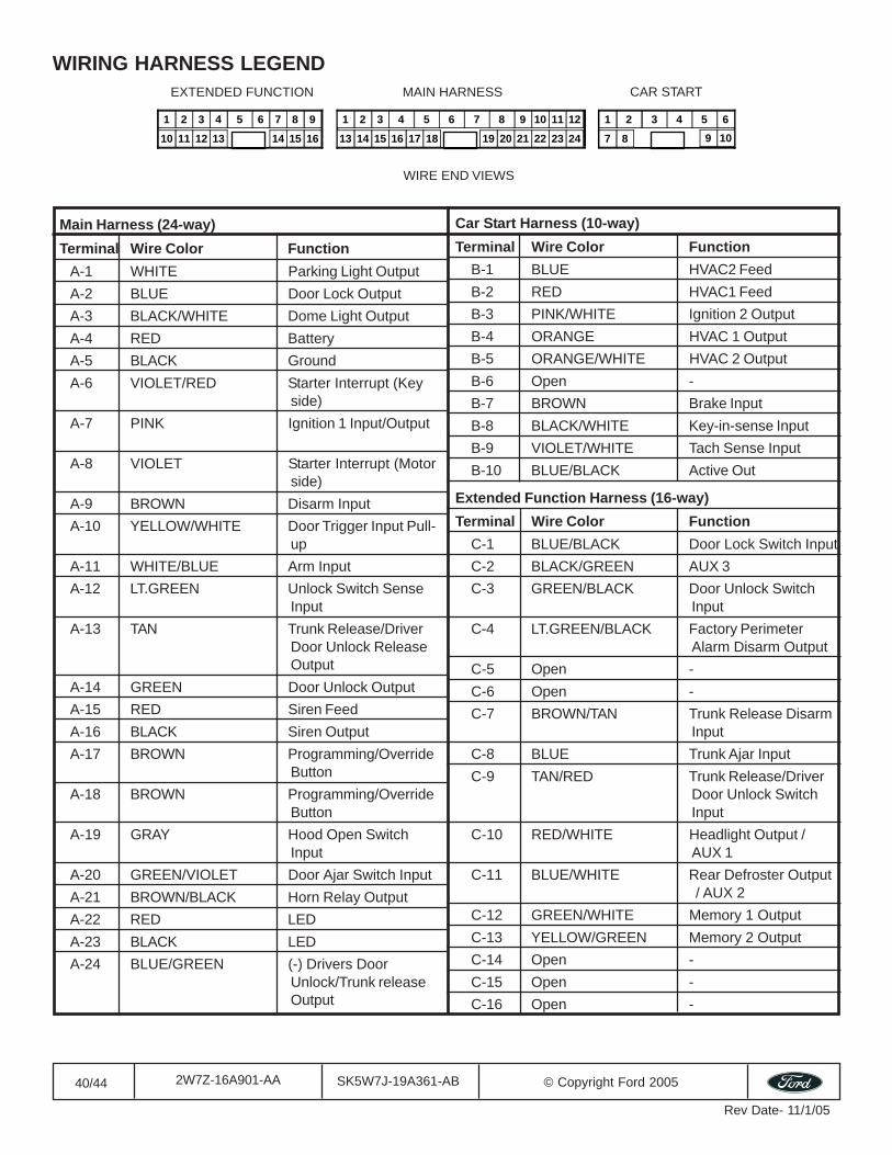
40/44 SK5W7J-19A361-AB © Copyright Ford 20052W7Z-16A901-AA
Rev Date- 11/1/05
5 1 2 3 4 6 7 8 9
10 11 12 13 14 15 16
9 10 11 12 1 2 3 4 5 6 7 8
13 14 15 16 17 18 19 20 21 22 23 24
2 3 5 1 4 6
7 8 9 10
WIRE END VIEWS
AMAIN HARNESS
BCAR START
BEXTENDED FUNCTION
WIRING HARNESS LEGEND
Main Harness (24-way)Terminal Wire Color Function
A-1 WHITE Parking Light OutputA-2 BLUE Door Lock OutputA-3 BLACK/WHITE Dome Light OutputA-4 RED BatteryA-5 BLACK GroundA-6 VIOLET/RED Starter Interrupt (Key
side)A-7 PINK Ignition 1 Input/Output
A-8 VIOLET Starter Interrupt (Motorside)
A-9 BROWN Disarm InputA-10 YELLOW/WHITE Door Trigger Input Pull-
upA-11 WHITE/BLUE Arm InputA-12 LT.GREEN Unlock Switch Sense
InputA-13 TAN Trunk Release/Driver
Door Unlock ReleaseOutput
A-14 GREEN Door Unlock OutputA-15 RED Siren FeedA-16 BLACK Siren OutputA-17 BROWN Programming/Override
ButtonA-18 BROWN Programming/Override
ButtonA-19 GRAY Hood Open Switch
InputA-20 GREEN/VIOLET Door Ajar Switch InputA-21 BROWN/BLACK Horn Relay OutputA-22 RED LEDA-23 BLACK LEDA-24 BLUE/GREEN (-) Drivers Door
Unlock/Trunk releaseOutput
Car Start Harness (10-way)Terminal Wire Color Function
B-1 BLUE HVAC2 FeedB-2 RED HVAC1 FeedB-3 PINK/WHITE Ignition 2 OutputB-4 ORANGE HVAC 1 OutputB-5 ORANGE/WHITE HVAC 2 OutputB-6 Open -B-7 BROWN Brake InputB-8 BLACK/WHITE Key-in-sense InputB-9 VIOLET/WHITE Tach Sense InputB-10 BLUE/BLACK Active Out
Extended Function Harness (16-way)Terminal Wire Color Function
C-1 BLUE/BLACK Door Lock Switch InputC-2 BLACK/GREEN AUX 3C-3 GREEN/BLACK Door Unlock Switch
InputC-4 LT.GREEN/BLACK Factory Perimeter
Alarm Disarm OutputC-5 Open -C-6 Open -C-7 BROWN/TAN Trunk Release Disarm
InputC-8 BLUE Trunk Ajar InputC-9 TAN/RED Trunk Release/Driver
Door Unlock SwitchInput
C-10 RED/WHITE Headlight Output /AUX 1
C-11 BLUE/WHITE Rear Defroster Output / AUX 2
C-12 GREEN/WHITE Memory 1 OutputC-13 YELLOW/GREEN Memory 2 OutputC-14 Open -C-15 Open -C-16 Open -
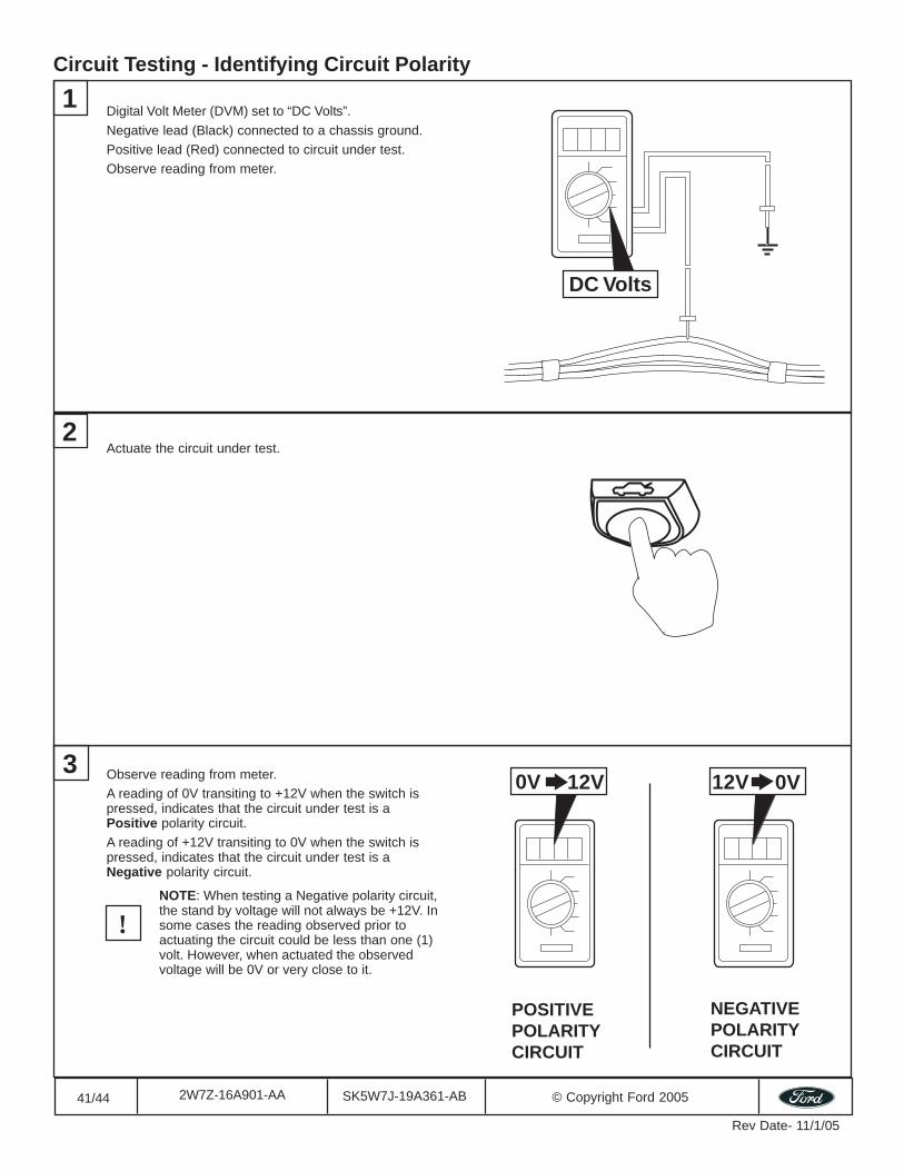
41/44 SK5W7J-19A361-AB © Copyright Ford 20052W7Z-16A901-AA
Rev Date- 11/1/05
Circuit Testing - Identifying Circuit Polarity
1
DC Volts
Digital Volt Meter (DVM) set to “DC Volts”.Negative lead (Black) connected to a chassis ground.Positive lead (Red) connected to circuit under test.Observe reading from meter.
2Actuate the circuit under test.
Observe reading from meter.A reading of 0V transiting to +12V when the switch ispressed, indicates that the circuit under test is aPositive polarity circuit.A reading of +12V transiting to 0V when the switch ispressed, indicates that the circuit under test is aNegative polarity circuit.
NOTE: When testing a Negative polarity circuit,the stand by voltage will not always be +12V. Insome cases the reading observed prior toactuating the circuit could be less than one (1)volt. However, when actuated the observedvoltage will be 0V or very close to it.
3
!
0V 12V
POSITIVEPOLARITYCIRCUIT
0V12V
NEGATIVEPOLARITYCIRCUIT
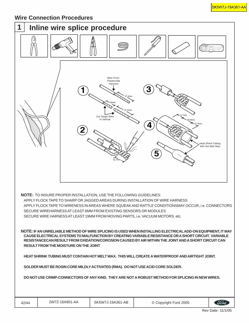
42/44 SK5W7J-19A361-AB © Copyright Ford 20052W7Z-16A901-AA
Rev Date- 11/1/05
1 Inline wire splice procedureWire Connection Procedures
Wire From Powercode
Harness
Cut Target WireIn Vehicle
Heat Shrint TubingWih Hot Melt Wax
NOTE: TO INSURE PROPER INSTALLATION, USE THE FOLLOWING GUIDELINES:APPLY FLOCK TAPE TO SHARP OR JAGGED AREAS DURING INSTALLATION OF WIRE HARNESSAPPLY FLOCK TAPE TO WIRENESS IN AREAS WHERE SQUEAK AND RATTLE CONDITIONSMAY OCCUR, i.e. CONNECTORSSECURE WIREHARNESS AT LEAST 6MM FROM EXISTING SENSORS OR MODULESSECURE WIRE HARNESS AT LEAST 19MM FROM MOVING PARTS, i.e. VACUUM MOTORS, etc.
NOTE: IF AN UNRELIABLE METHOD OF WIRE SPLICING IS USED WHEN INSTALLING ELECTRICAL ADD-ON EQUIPMENT, IT MAYCAUSE ELECTRICAL SYSTEMS TO MALFUNCTION BY CREATING VARIABLE RESISTANCE OR A SHORT CIRCUIT. VARIABLERESISTANCECAN RESULT FROM OXIDATION/COROSION CAUSED BY AIR WITHIN THE JOINT AND A SHORT CIRCUIT CANRESULT FROM THE MOISTURE ON THE JOINT
HEAT SHRINK TUBING MUST CONTAIN HOT MELT WAX. THIS WILL CREATE A WATERPROOF AND AIRTIGHT JOINT.
SOLDER MUST BE ROSIN CORE MILDLY ACTIVATED (RMA). DO NOT USE ACID CORE SOLDER.
DO NOT USE CRIMP-CONNECTORS OF ANY KIND. THEY ARE NOT A ROBUST METHOD FOR SPLICING IN NEW WIRES.
dkline
Text Box
SK5W7J-19A361-AA
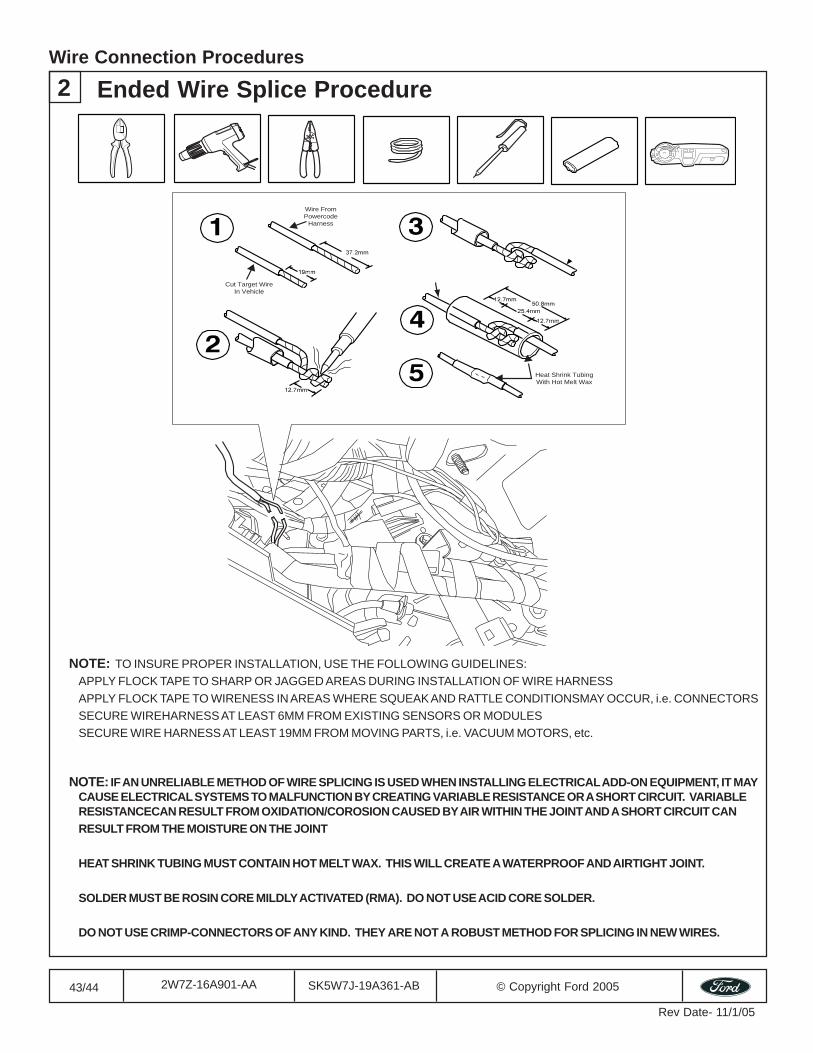
43/44 SK5W7J-19A361-AB © Copyright Ford 20052W7Z-16A901-AA
Rev Date- 11/1/05
2 Ended Wire Splice ProcedureWire Connection Procedures
NOTE: TO INSURE PROPER INSTALLATION, USE THE FOLLOWING GUIDELINES:APPLY FLOCK TAPE TO SHARP OR JAGGED AREAS DURING INSTALLATION OF WIRE HARNESSAPPLY FLOCK TAPE TO WIRENESS IN AREAS WHERE SQUEAK AND RATTLE CONDITIONSMAY OCCUR, i.e. CONNECTORSSECURE WIREHARNESS AT LEAST 6MM FROM EXISTING SENSORS OR MODULESSECURE WIRE HARNESS AT LEAST 19MM FROM MOVING PARTS, i.e. VACUUM MOTORS, etc.
NOTE: IF AN UNRELIABLE METHOD OF WIRE SPLICING IS USED WHEN INSTALLING ELECTRICAL ADD-ON EQUIPMENT, IT MAYCAUSE ELECTRICAL SYSTEMS TO MALFUNCTION BY CREATING VARIABLE RESISTANCE OR A SHORT CIRCUIT. VARIABLERESISTANCECAN RESULT FROM OXIDATION/COROSION CAUSED BY AIR WITHIN THE JOINT AND A SHORT CIRCUIT CANRESULT FROM THE MOISTURE ON THE JOINT
HEAT SHRINK TUBING MUST CONTAIN HOT MELT WAX. THIS WILL CREATE A WATERPROOF AND AIRTIGHT JOINT.
SOLDER MUST BE ROSIN CORE MILDLY ACTIVATED (RMA). DO NOT USE ACID CORE SOLDER.
DO NOT USE CRIMP-CONNECTORS OF ANY KIND. THEY ARE NOT A ROBUST METHOD FOR SPLICING IN NEW WIRES.
Wire FromPowercode
Harness
Cut Target WireIn Vehicle
Heat Shrink TubingWith Hot Melt Wax
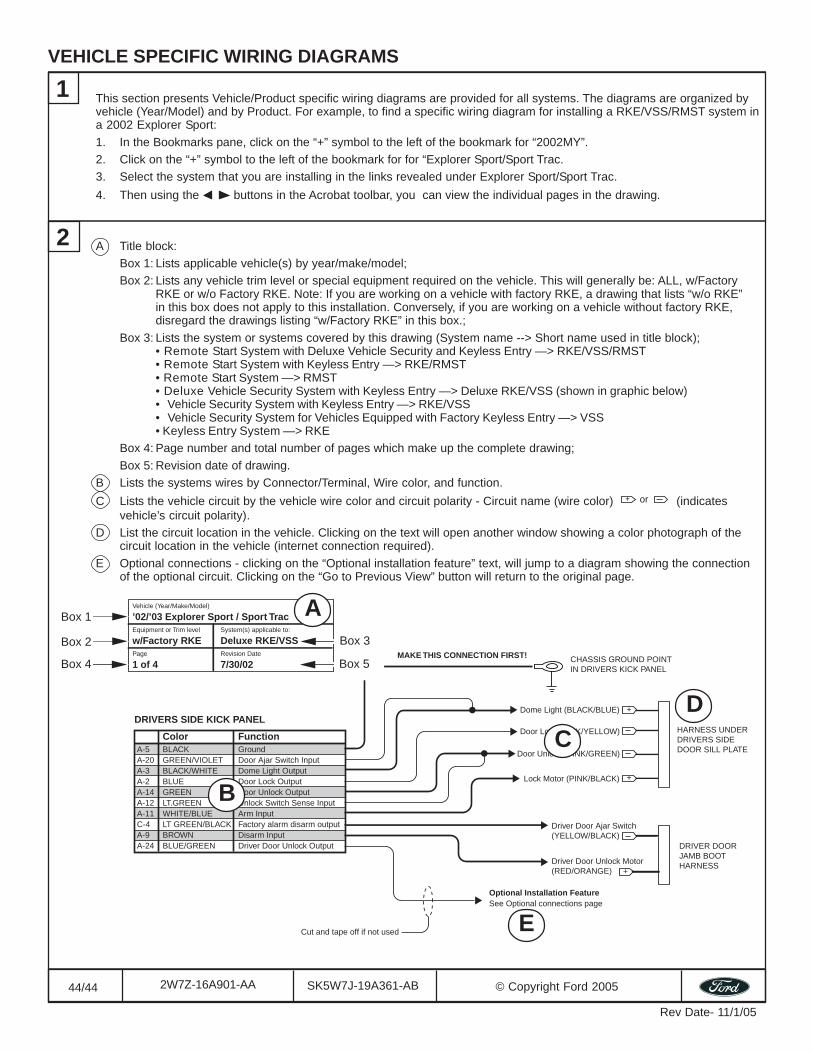
44/44 SK5W7J-19A361-AB © Copyright Ford 20052W7Z-16A901-AA
Rev Date- 11/1/05
Color FunctionA-5 BLACK GroundA-20 GREEN/VIOLET Door Ajar Switch InputA-3 BLACK/WHITE Dome Light Output A-2 BLUE Door Lock Output A-14 GREEN Door Unlock OutputA-12 LT.GREEN Unlock Switch Sense InputA-11 WHITE/BLUE Arm Input C-4 LT GREEN/BLACK Factory alarm disarm outputA-9 BROWN Disarm InputA-24 BLUE/GREEN Driver Door Unlock Output
DRIVERS SIDE KICK PANEL
CHASSIS GROUND POINTIN DRIVERS KICK PANEL
MAKE THIS CONNECTION FIRST!
HARNESS UNDERDRIVERS SIDEDOOR SILL PLATE
Dome Light (BLACK/BLUE) +
+
DRIVER DOORJAMB BOOTHARNESS
+
Door Lock (PINK/YELLOW)
Door Unlock (PINK/GREEN)
Lock Motor (PINK/BLACK)
Driver Door Unlock Motor(RED/ORANGE)
Driver Door Ajar Switch(YELLOW/BLACK)
Cut and tape off if not used
Optional Installation FeatureSee Optional connections page
Vehicle (Year/Make/Model)
’02/’03 Explorer Sport / Sport TracEquipment or Trim level System(s) applicable to:
w/Factory RKE Deluxe RKE/VSSPage Revision Date
1 of 4 7/30/02
VEHICLE SPECIFIC WIRING DIAGRAMS
This section presents Vehicle/Product specific wiring diagrams are provided for all systems. The diagrams are organized byvehicle (Year/Model) and by Product. For example, to find a specific wiring diagram for installing a RKE/VSS/RMST system ina 2002 Explorer Sport:1. In the Bookmarks pane, click on the “+” symbol to the left of the bookmark for “2002MY”.2. Click on the “+” symbol to the left of the bookmark for for “Explorer Sport/Sport Trac.3. Select the system that you are installing in the links revealed under Explorer Sport/Sport Trac.4. Then using the buttons in the Acrobat toolbar, you can view the individual pages in the drawing.
1
A Title block:Box 1: Lists applicable vehicle(s) by year/make/model;Box 2: Lists any vehicle trim level or special equipment required on the vehicle. This will generally be: ALL, w/Factory
RKE or w/o Factory RKE. Note: If you are working on a vehicle with factory RKE, a drawing that lists “w/o RKE”in this box does not apply to this installation. Conversely, if you are working on a vehicle without factory RKE,disregard the drawings listing “w/Factory RKE” in this box.;
Box 3: Lists the system or systems covered by this drawing (System name --> Short name used in title block);• Remote Start System with Deluxe Vehicle Security and Keyless Entry —> RKE/VSS/RMST• Remote Start System with Keyless Entry —> RKE/RMST• Remote Start System —> RMST• Deluxe Vehicle Security System with Keyless Entry —> Deluxe RKE/VSS (shown in graphic below)• Vehicle Security System with Keyless Entry —> RKE/VSS• Vehicle Security System for Vehicles Equipped with Factory Keyless Entry —> VSS• Keyless Entry System —> RKE
Box 4: Page number and total number of pages which make up the complete drawing;Box 5: Revision date of drawing.
B Lists the systems wires by Connector/Terminal, Wire color, and function.C Lists the vehicle circuit by the vehicle wire color and circuit polarity - Circuit name (wire color) + or (indicates
vehicle’s circuit polarity).D List the circuit location in the vehicle. Clicking on the text will open another window showing a color photograph of the
circuit location in the vehicle (internet connection required).E Optional connections - clicking on the “Optional installation feature” text, will jump to a diagram showing the connection
of the optional circuit. Clicking on the “Go to Previous View” button will return to the original page.
2
B
CD
E
Box 2
Box 1
Box 4
Box 3
Box 5
A