Warning - file.yizimg.comfile.yizimg.com/492225/2016112-15127923.pdf · Warning Thanks for your...
22
Transcript of Warning - file.yizimg.comfile.yizimg.com/492225/2016112-15127923.pdf · Warning Thanks for your...


Warning
Thanks for your purchase of ETCR3200 Double Clamp Multi-function Grounding Resistance Tester of our company. For better use of the product, please make sure:
---To read this user manual in details. ---To abide by the safety regulations and precautions strictly.
u The tester is conforming to IEC61010 on design, production and test. u Under any circumstance, it shall pay special attention on safety in use of this tester. u Pay attention to words and symbols stick on the Tester. u Pay attention to the direction of current of the clamp. u It shall make sure that tester and accessories are in good condition before use; it can be used only
when there is no damaged, naked or broken part in testing wires or insulation layer. u During measurement, it is forbidden to touch bare conductors and circuit under measurement. u Before measurement, please confirm whether FUNCTION rotary switch has been set within the
proper measuring range. u Confirm that connector plug of lead has been inserted in the tester interface closely. u Please don’t impose over 100V A.C. or D.C. voltage on the part between testing end and interface.
Otherwise, it may have damage on the tester. u Please don’t measure in an inflammable place. The flame sparkle maybe cause explosion. u During usage of tester, please stop using it when exposed metal is caused by broken enclosure or
testing wires. u Please don’t keep or store the tester in the spot with high-temperature and moisture, or
condensation, and under direct daylight radiation for a long time. u For replacing battery, please confirm testing wire has moved apart the meter, and FUNCTION rotary
switch is in “OFF” position. u Please put the used batteries in appointed collection place. u The Tester has no auto shut-off function. Please set FUNCTION rotary switch to “OFF” after usage. u When the meter displays battery low voltage symbol ,and you need to replace the battery in
time. u If the Tester is not going to be used for a long period, remove the battery. u Pay attention to measuring range and usage environment stipulated for the Tester. u This measuring device is only to be used, disassembled, adjusted and repaired by qualified
personnel with authorization. u When it may cause hazard by continuous use for the reason of the Tester itself, it shall immediately
stop using it and deposit it at once, leaving it for disposal by authorized agency. u For risk of danger icon in manual , users must perform safety operations strictly in compliance
with the manual content.
2
CONTENT Ⅰ. Brief introduction .................................................................................................... 3 Ⅱ. Technical specification ............................................................................................ 3
1.Base Conditions and Working Conditions .......................................................... 3 2.General specification ......................................................................................... 3 3.Intrinsic error and performance indicators under base conditions .................... 5
Ⅲ. Structure of tester ................................................................................................. 6 Ⅳ. LCD display ........................................................................................................... 6 Ⅴ. Principle of measurement ...................................................................................... 7 Ⅵ. Operation Methods .............................................................................................. 9
1.Switch On/Off .................................................................................................... 9 2.Battery Voltage Check ....................................................................................... 9 3.4 wires Precise Earth Resistance Measurement ............................................... 10 4.3-Wires Earth Resistance Measurement .......................................................... 11 5.2-Wires Simple Measurement ......................................................................... 11 6.4 wires selection method to measure the grounding resistance ...................... 12 7.3 wires selection method to measure grounding resistance ............................ 14 8.Double clamp method to measure grounding resistance ................................ 14 9.Soil Resistivity Measurement........................................................................... 15 10.DC resistance test .......................................................................................... 16 11.AC current measurement .............................................................................. 17 12.Earth Voltage Measurement .......................................................................... 18 13.Back light control ........................................................................................... 18 14.Alarm Settings ............................................................................................... 18 15.Data Lock/Storage ......................................................................................... 18 16.Data Reading/Deletion .................................................................................. 19 17.Data Upload .................................................................................................. 19
VII. Battery Replacement .......................................................................................... 19 Ⅷ. ACCESSORIES ..................................................................................................... 20

3
Ⅰ. Brief introduction ETCR3200 Double Clamp Multi-function Grounding Resistance Tester specially design for the measurement of earth resistance, soil resistivity, earth voltage, leakage current of grounding line, AC current, DC resistance. Adopting the latest digital technology, precise 4-pole, 3-pole and simple 2-pole method, selection method, double clamp method to measure grounding resistance, for earth resistance measurement; large caliber clamp design, can use to measure the grounding system which adopt large-scale down conductor; can flexibly and precisely measure the value of grounding resistance in every complicated situation like single point grounding, grounding mesh; it is not need to disconnect any parallel connection pole when measuring parallel-grounding, and massively improve the convenience when measuring. Importing FFT and AFC technology, with a unique function of anti-interference capability and the ability to adapt to the environment, consistency of repeat testing, to ensure high precision, high stability and reliability for prolonged measure, which is widely used in electric power, telecommunications, meteorology, oil field, construction, lightning protection, industrial electrical equipment and other earth resistance, soil resistivity, earth voltage, AC voltage measurement. ETCR3200 Double Clamp Multi-function Grounding Resistance Tester is composed of host machine, monitoring software, testing wires, auxiliary ground pillars, communication wires and others. The large LCD display of host machine is with blue backlight and bar graph indicating that can be seen clearly. At the same time it can store 100 sets of data, fulfilling historical inquiry and online real-time monitoring through monitoring software, dynamic display, and alarm indicator, auto-shut down and with the functions like historical data access, reading, preservation, report forms, printing and so on. Ⅱ. Technical specification 1.Base Conditions and Working Conditions
Influence Quantity Base Condition Working Conditions Remark
Ambient Temp 23℃±1℃ -10℃-40℃ ---- Ambient Humidity 40%-60% <80% ---- Working Voltage 9V±0.1V 9V±1.5V rC、rP
Auxiliary Earth Resistance <100Ω <30kΩ ---- Interference Voltage None <20V ---- Interference Current none <2A
Electrode Distance when measuring R a>5d a>5d ---- Electrode Distance when measuring ρ a>20h a>20h ----
2.General specification Function Measure grounding resistance, soil resistivity; Measurement of earth voltage,
AC voltage, leakage current of AC current
Power Supply DC 9V(Zn-Mn dry battery R14S 1.5V 6 PCS, continuous standby for 300 hours )
Backlight Blue screen backlight, suitable for dim places
Measuring Mode Precise 4-pole measurement, 3-pole measurement, simple 2-pole measurement, selection method, double clamp method measure grounding resistance
Measuring Method
2/3/4 pole method: change-pole method, measurement current 20mA Max Selection method: change-pole method, measurement current 20mA Max Double clamp method: disconnect mutual inductance method, measurement current 1mA Max Soil Resistivity: 4-pole measurement (Wenner method) DC resistance: change-pole method AC current: mutual inductance method Earth Voltage: average rectification(between P(S)-ES)
Test Voltage Wave Sine wave
Test Frequency 128Hz/111Hz/105Hz/94Hz(AFC) Short-circuit Test AC 20mA max

4
Current Open-circuit Test
Current AC 40V max
Electrode Distance Range Can be set 1m-100m
Display Mode 4-digital super-large LCD display, blue screen backlight Measuring Indicator
During measurement, LED flash indicator, LCD countdown display, progress bar indicator
LCD Frame Dimension 128mm×75mm
LCD Window Dimension 124mm×67mm
Dimension L×W×H: 215mm×190mm×95mm Size of clamp LxWxH:185mmX115mmX43mm Standard Test
Wire 4 wires: each for red 20m, black 20m, yellow 10m, and green 10m
Simple Test Wire 2 wires: each for red 1.6m and black 1.6m Auxiliary
Grounding Rod 4 wires: Φ10mm×150mm Over 5000 times (Short-circuit test, interval time should be at least 30 seconds)
Clamp 2pc :1 blue-black plug and 1 red-black. Caliber of clamp Φ68mm
Turn Ratio 1000 :1 Lead line of
clamp 2m
Measuring Rate AC current: about 2 times/second Voltage to ground: about 2 times/second Earth resistance, soil resistivity: about 7 seconds/time
Measuring Times Over 5000 times (Short-circuit test, interval time should be at least 30 Voltage of circuit AC 600V
RS232 Interface RS232 interface, software supervision, storage data can be uploaded to computer, saved or printed.
Communication Wire One piece of RS232 communication wire, with length 1.5m
Data Hold Data hold function: “HOLD” icon display Data Storage 2000 sets, “MEM” storage indicator, flash display “FULL” icon to indicate
Data Read Data read function: “READ” icon display Overflow Display Exceeding measuring range overflow function: “OL” icon display
Low current direction of
clamp
When use select method or double clamp to measure, and the current signal CT2 receive is lower than 0.5mA,and” ” display, then would check the direction of CT2 clamp into
Interference Test Recognize interference signal automatically, “NOISE” icon display when interference voltage exceed 5V
Auxiliary Grounding Test
Can measure auxiliary earth resistance, 0.00KΩ-30kΩ(100R+rC<50kΩ, 100R+rP<50kΩ)
Alarm Function When measuring value exceeds alarm setting value, there is “Toot-toot-toot” alarm hint
Battery Voltage When battery voltage decreases to about 7.5V, battery voltage low icon will display, reminding to replace battery.
Auto-shut off Automaticlly shut down 15minutes after booting
Power Consumption
Standby: about 25mA Max(Backlight shut off) Boot 25mA Max(without backlight) Measurement: about 150mA Max(Backlight shut off)
Weight
Total weight: 8.05kg (including package) Tester: 1653g (including battery) Testing wires: 1560g Auxiliary grounding rods: 935g (4pcs)
Working -10℃-40℃, below 80%rh
5
Temperature & Humidity Storage
temperature & humidity
-20℃-60℃, below 70%rh
Overload Protection
Earth resistance: between each interfaces of C(H)-E、P(S)-ES, AC 280V/3 seconds
Insulation Resistance Over 20MΩ (between circuit and enclosure it is 500V)
Withstanding Voltage AC 3700V/rms. (Between circuit and enclosure)
Electromagnetic Features IEC61326(EMC)
Protection Type
IEC61010-1 (CAT Ⅲ 300V、CAT IV 150V、Pollution 2), IEC61010-031; IEC61557-1 (Earth resistance); IEC61557-5 (Soil resistivity); JJG 366-2004(Grounding resistance meter) JJG 1054-2009(Clamp grounding resistance meter)
3.Intrinsic error and performance indicators under base conditions Function Measurement
Range Intrinsic Error Resolution
2/3/4 pole method measure earth
resistance (R)
0.00Ω-29.99Ω ±2%rdg±5dgt 0.01Ω 30.0Ω-299.9Ω ±2%rdg±3dgt 0.1Ω 300Ω-2999Ω ±2%rdg±3dgt 1Ω
3.00kΩ-30.00kΩ ±4%rdg±3dgt 10Ω Selection method
to measure grounding
resistance(○R )
0.00Ω-29.99Ω ±2%rdg±5dgt 0.01Ω 30.0Ω-299.9Ω ±2%rdg±3dgt 0.1Ω
300Ω-3000Ω ±2%rdg±3dgt 1Ω Double clamp
method to measure grounding
resistance(○R )
0.01Ω-0.99Ω ±10%rdg±5dgt
0.01Ω
1.0Ω-29.9Ω 0.1Ω 30Ω-100Ω 1Ω
Soil Resistivity (ρ)
0.00Ωm-99.99Ωm
According to the precision of R
(ρ=2πaR a:1 m-100m,
π=3.14)
0.01Ωm 100.0Ωm-999.9Ωm 0.1Ωm 1000Ωm-9999Ωm 1Ωm
10.00kΩm-99.99kΩm 10Ωm
100.0kΩm-999.9kΩm 100Ωm
1000kΩm-9000kΩm 1kΩm
Earth Voltage(50Hz/60Hz) AC 0.0-100V ±2%rdg±3dgt 0.1V
AC current(50Hz/60Hz) 0.0mA-600.0A ±2%rdg±3dgt 0.01mA
Note: 1.rC max or rPmax: additive error≤±5%rdg±5dgt (rC max: 4kΩ+100R<50kΩ, rP max: 4kΩ+100R<50kΩ)
2.when interference by 5V voltage, the additive error ≤±5%rdg±5dgt

6
Ⅲ. Structure of tester
1. LCD 2. Button area 3. Rotary switch for selecting function 4. RS232 interface 5. Interface of testing wires 6.C1 interface (same as CT2) 7. P(s) interface (voltage pole) 8. C (H) interface (current pole) 9. E interface (grounding pole) 10.ES interface (Auxiliary grounding pole) 11. C2 interface (public interface of CT2) 12.Testing line 13. Auxiliary grounding rod 14.Simple testing line 15. Stimulant current clamp CT1 16.Receive clamp CT2 17. Stimulant current clamp CT1 connecting interface, red banana plug is dotted terminal, black is
public terminal 18. Receive current clamp CT2 connecting interface, blue banana plug is dotted terminal, black is public terminal
Ⅳ. LCD display

7
1. Bar graph of testing process(dynamically display the process of measurement,) 2. Alarm direction symbol (the icon will display when the alarm function has been boot, and it will
flash display when the value is over the alarm value) 3. The direction of overvoltage(it will display when the voltage to be measure is over 30V, safety
warning ) 4. AC direction 5. Data hold direction(it will display when press MEM to keep the data) 6. Data read direction(it will display when press MEM for 3 second to read the data) 7. Data storage direction(it will display when press MEM to hold the data and store the data at the
same time) 8. Signal interference direction(it will display when the interference voltage is over 5V) 9. Low voltage direction(it will display when the voltage of battery is below 7.5V ) 10. Direction of the number of sets of data has been stored 11. Direction of the current signal of current clamp CT2 is too low(it will display when the current
signal CT2 has received is lower than 0.5mA, it may because CT2 clamp into the opposite direction)
12. Interference pole direction(it will display when the pole has been interfered) 13. Data display 14. Unit symbol of voltage 15. Unit symbol of resistance, soil resistivity, current, length
Ⅴ. Principle of measurement 1. 3 wires and 4 wires method to measure grounding resistance adopt rate current pole changing
method (suit for accurately measure the single point grounding system), it means to measure the AC rate current I between grounding electrode object E and current electrode C(H),calculating the potential difference between grounding electrode E and voltage electrode P(s),base on the formula R=V/I to calculate the grounding resistance R. To ensure the accuracy of measurement, we adopt 4 wires method, add ES auxiliary grounding electrode, ES and E clip at the same point of the grounding body when testing.
2. Selection method to measure grounding resistance adopt current change-pole method (suit for
measuring one of earth screen grounding resistance of parallel connection grounding system without grounding wire disconnect.), add AC current I between Re1 Re2 Re3 grounding electrode and C(H)

8
electrode, measure I3 which flow through Re3 by CT2, measure the potential difference V between Re3 grounding electrode and P(s) electrode, calculate the grounding resistance Re3 base on formula Re3=v/I3. To ensure the accuracy of measurement, adopt 4 wires method, add ES auxiliary electrode, ES and E clip at the same point of the grounding body when testing.
3. Double clamp method to measure grounding resistance (suit for measurement of multiple
independent point parallel connecting grounding system without auxiliary rod), generate an AC electromotive force V by excitation clamp CT1; under the effect of AC electromotive force V, generate a current I in the circuit, and get its value by CT2; base on formula R=V/I, calculate the value of resistance. In the graph below, R=Re+R1//R2//R3// ··· Rn-1//Rn, if Re+R1//R2//R3//···Rn-1//Rn (resistance of multiple grounding point parallel connect) is much less than Re, then R≈Re.
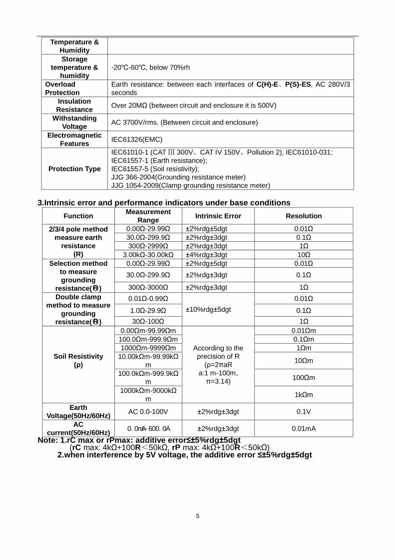
4. The measurement of Soil resistivity (ρ) adopt 4-pole method (wenner): There is a AC current I
between E grounding electrode and C(H) current electrode, find the potential difference V between P(S) voltage electrode and ES auxiliary grounding electrode, the potential difference V divided by AC current I is earth resistance R, electrode distance is a(m), then soil resistivity can be got according to formula ρ=2πaR(Ωm). If the electrode distance of C(H)-P(S) is equal to P(S)-ES (both is a) that is for wenner method. In order to simple the calculation, please make electrode distance a far more than embedding depth h, generally should meet a>20h, as shown below.
9
5. 2/3/4 wires DC resistance measurement adopt rated current change-pole method(suit for
equipotential bonding resistance measurement test),it means to measure the direct rated current I flow through measurement target R, find the potential difference V of both ends of R, calculate the resistance value of R base on formula R=V/I. To insure the accuracy of measurement, adopt 4 wires method, and add ES auxiliary rod, ES and E clip at the same point of the grounding body when testing.
6. Operating error (B) of the method mention above is under the nominal working conditions, it can be found by the inherent error (A) and variable error (Ei). A: Inherent error E2: Variation due to power supply voltage E3: Variation due to temperature change; E4: Variation due to interference voltage change E5: Variation due to contact electrode resistance
7. Adopt average rectification method to measure AC leakage current. 8. Adopt average rectification method to measure grounding voltage.
Ⅵ. Operation Methods
1.Switch On/Off Rotate FUNCTION rotary switch to fulfill switch on and off. When rotary switch button displays “OFF” for shut-off. The tester has no auto shut-off function, so please shut it off after usage in case of battery consumption saving.
2.Battery Voltage Check After switch on, if LCD displays low battery voltage icon “ ”, which indicates that battery voltage is low, and please replace the battery in compliance with instructions. Adequate battery power can ensure the accuracy of measurement.

10
3.4 wires Precise Earth Resistance Measurement
In the testing of earth resistance, should firstly confirm the earth voltage of grounding wire, the voltage between C(H) and E or P(s) and ES must under 20V, the meter showing NOISE symbols when the earth voltage exceed 5V, and the measured value of earth resistance may produce error. At this time, firstly interrupt power supply to grounding equipment, make sure the earth voltage decrease, and then test earth resistance again.
4-wires measurement: The 4-wires method can eliminate influence of contact resistance (usually result from dirty or rusty) between measured grounding body, auxiliary grounding rods, test clips, meter’s input interface. The 4-wires method can also eliminate influence of line resistance. So it is better than 3-wires measurement. As shown below: Start from the measured body, interval 5m-20m, respectively insert P(S), C(H) auxiliary grounding rods deep into the earth in a straight line, and then connect testing wires (black, green, yellow, red) from E, ES, P(S), C(H) interfaces corresponding to measured earth electrode E, auxiliary voltage electrode P(S), auxiliary current electrode C(H). The distance from measured grounding body to current electrode C(H), should at least
five times deeper than the embedded depth of measured grounding body, or the embedded electrode depth (d). When measuring the total earth resistance of complex grounding system, d is the length of the biggest diagonal line of this grounding system. Testing wires can’t be winded together, or may affect the measuring accuracy.
For multi independent grounding system or larger earth net, 50m or longer testing wire is optional, as shown below:
R=r1 r2 r3 r4 r5 r6 … rn∥ ∥ ∥ ∥ ∥ ∥ ∥ (r1…rn are all independent grounding points) R—— The reading value on meter, the total earth resistance of the grounding system. r1…rn—— All are independent grounding points, each points have no connection together under the

11
ground. rC—— The earth resistance rC of auxiliary current electrode C(H). rP—— The earth resistance rP of auxiliary voltage electrode P(S). n—— Number of independent grounding point, more points, smaller the R value. After finishing wires connection, firstly rotate FUNCTION rotary switch to “REARTH”, press “START” button to start testing. During testing, display countdown and process bar indicator. Stable earth resistance value is shown when finish testing. After testing, Press “SET” button, is able to read the earth resistance rC of auxiliary current electrode C(H) and earth resistance rP of auxiliary voltage electrode P(S), and then automatically return display of measured earth resistance R. As shown below, the measured earth resistance is 2.05Ω, already stored 8 sets of data. the earth resistance rC of auxiliary current electrode C(H) is 0.36KΩ, the earth resistance rP of auxiliary voltage electrode P(S) is 0.27KΩ.
4.3-Wires Earth Resistance Measurement 3-wires measurement: As shown below, short-circuit ES and S interface, which is 3-wires measurement. The operation of meter is the same with 4-wires measurement. The 3-wires method can’t eliminate influence of line resistance, also can’t eliminate influence of contact resistance between meter and testing wires, testing wires and auxiliary grounding rods. Meanwhile, oxidation layer on measured grounding body must be removed when measuring.
5.2-Wires Simple Measurement 2-wires method: This method is a simple method for measurement that does not use auxiliary grounding rod, taking the earth electrode with the minimal existing earth ground resistance value as auxiliary earth electrode, and connecting by two simple testing wires (in which C(H)-P(S), E-ES interfaces are in short circuit). It can make use of metal pipes, fire hydrants and other metal buried objects, common grounding of commercial electric power system or lightning protection earth ground electrode and others to replace auxiliary grounding rods C(H),P(S), and pay attention to remove oxide layer on the
connection point of the selected metal auxiliary grounding object when making measurement.
Wire connection is as following figure, and refers to 4-wires measurement for other operations. When select commercial use power supply system earth as auxiliary earth electrode, it
must use detector to confirm that is it the earth ground electrode for commercial use power supply system, otherwise the breaker may start, it is dangerous. Using 2-wires simple method for measuring earth resistance, try to choose a grounding body which has a small re value as auxiliary grounding electrode, so that the reading value is more close to the real value. The metal pipes, metal fire hydrant has priority in choosing auxiliary grounding electrodes.

12
2-wires simple method for measurement of earth ground resistance, its reading on tester is the total value of earth ground resistance value of measured grounding object and that of commercial grounding object, that is: R=RX+re, In which: R is the tester reading value; RX is the earth ground resistance value of measured grounding object; re is the earth ground resistanceof common grounding object like commercial use power system. Then, the earth ground resistance value of measured grounding object is: RX=R-re
6.4 wires selection method to measure the grounding resistance In the testing of earth resistance, should firstly confirm the earth voltage of grounding wire,
the voltage between C(H) and E or P(s) and ES must under 20V, the meter showing NOISE symbols when the earth voltage exceed 5V, and the measured value of earth resistance may produce error. At this time, firstly interrupt power supply to grounding equipment, make sure the earth voltage decrease, and then test earth resistance again.
4 wires selection method can precisely measure the grounding resistance of one of grounding body under the situation of with disconnect the grounding line, 4-wires method can eliminate influence of contact resistance (usually result from dirty or rusty) between measured grounding body, auxiliary grounding rods, test clips, meter’s input interface. The 4-wires method can also eliminate influence of
13
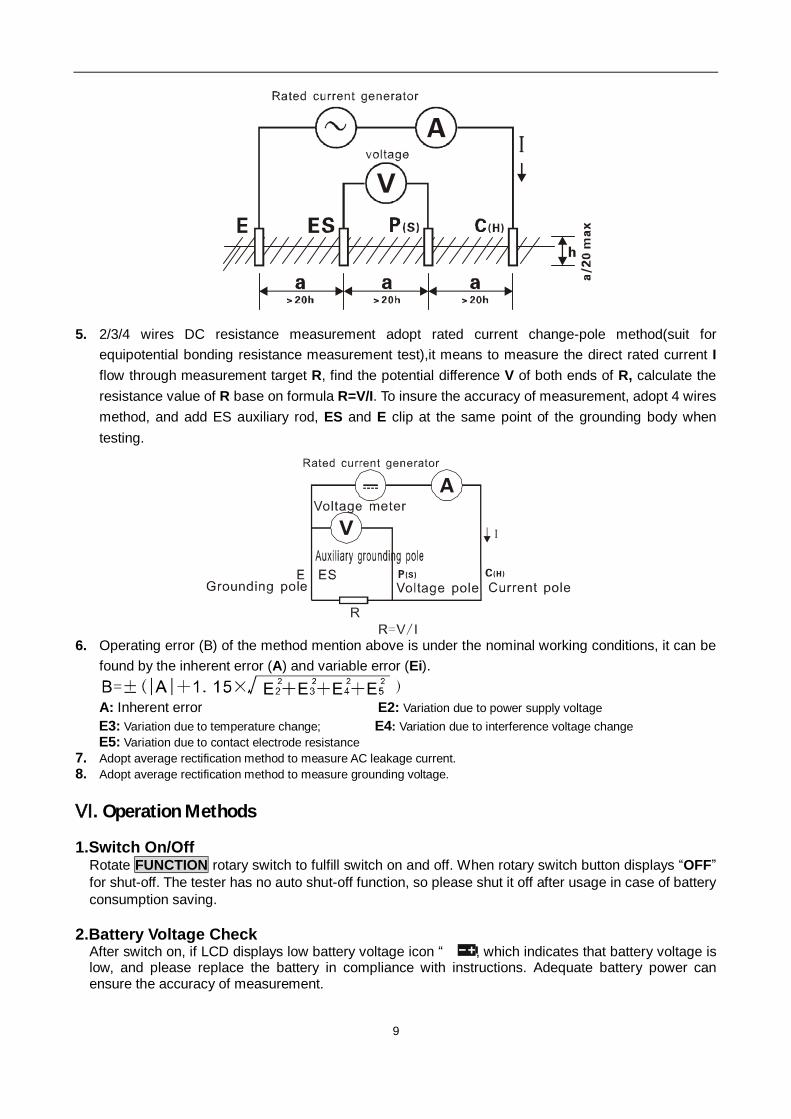
line resistance. So it is better than 3-wires measurement. As shown below: Start from the measured body, respectively insert P(S), C(H) auxiliary grounding rods deep into the earth in a straight line, and then connect testing wires (black, green, yellow, red) from E, ES, P(S), C(H) interfaces corresponding to measured earth electrode E, auxiliary voltage electrode P(S), auxiliary current electrode C(H), insert the blue plug of CT2, in to the C1 interface of meter, black plug insert in to the C2 interface, current clamp vise the down lead of the grounding body being measured, pay attention to the direction of current clamp, the accuracy can be ensure only if the current flow from front of the clamp. When testing the grounding resistance, firstly confirm the value of leakage of the grounding
line, and the current of the grounding line should below 2A; current of grounding line over 100mA, there would be error with the value of grounding resistance, At this time, firstly interrupt power supply to grounding equipment, make sure the earth voltage decrease, and then test earth resistance again. At the same time have to ensure the current flow from front of the clamp; otherwise, the grounding resistance can’t be test in normal way. When “ ” display in the screen, it means current signal CT2 received is too low, should check whether CT2 has clamped the wires in a right way, the direction of CT2 is right, and the auxiliary rod is bad contact, etc. The current signal CT2 receive is come from underground, the positive side of CT2 is the direction of the current flow inside, and it means that one side with CT2 symbol face to ground and vise the grounding line.
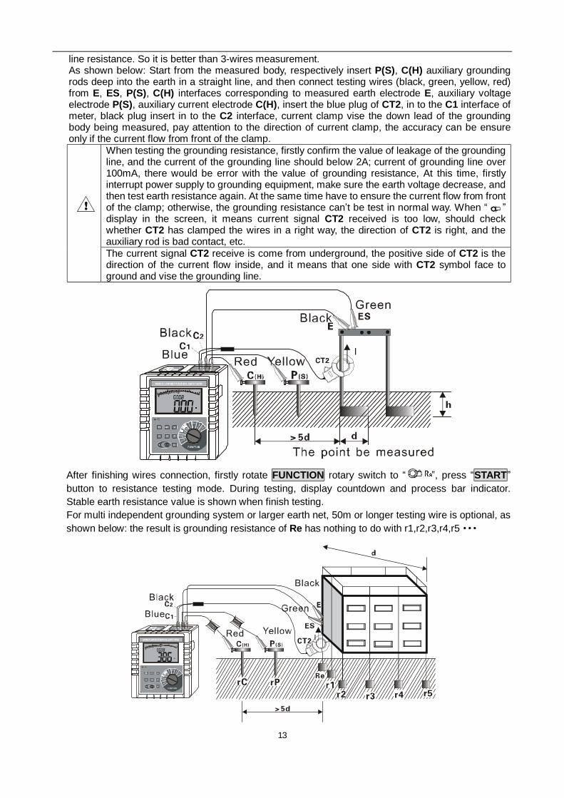
After finishing wires connection, firstly rotate FUNCTION rotary switch to “ ”, press “START” button to resistance testing mode. During testing, display countdown and process bar indicator. Stable earth resistance value is shown when finish testing. For multi independent grounding system or larger earth net, 50m or longer testing wire is optional, as shown below: the result is grounding resistance of Re has nothing to do with r1,r2,r3,r4,r5···

14
As shown below: use 4 wires selection method can precisely measure the grounding resistance Re of the tower under the condition of the grounding line is connected; the value of grounding resistance is the result of Re parallel connect with R1, R2, R3 if use traditional way like 3 wires 4 wires method under the condition of the grounding line is connected; if there is a fault with Re, at the same time, the value after R1, R2, R3 parallel connect is small, in this situation, traditional 3 wires 4 wires method is hard to find the fault point, and it is easy to be ignored.
7.3 wires selection method to measure grounding resistance 3 wires selection method: as show below, 3 wires selection method means shot circuit the interface ES, E of meter, operation method is the same as 4 wires method. 3 wires selection method can’t eliminate the influence of floating line resistance to the measurement, can’t eliminate the influence of the changing contact resistance between meter and testing wire, testing wire and auxiliary rod. Before testing, should get rid of the oxide layer of on the surface of the grounding body.
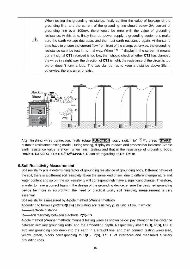
8.Double clamp method to measure grounding resistance Double clamp method is suit for measuring the independent multipoint grounding system, as show below; multipoint grounding system doesn’t need auxiliary rod to measure grounding resistance. Insert the red plug of CT1 into the C (H) interface, and insert the blue plug of CT2 into C1 interface of meter, the black plug insert the C2 interface, clamp the circuit with two current clamp, the two clamp have to clamp the circuit like the graph shows and keep a distance above 30cm, the position of these two clamp can’t be change with each other, otherwise, there is an error exist.
15
When testing the grounding resistance, firstly confirm the value of leakage of the grounding line, and the current of the grounding line should below 2A; current of grounding line over 100mA, there would be error with the value of grounding resistance, At this time, firstly interrupt power supply to grounding equipment, make sure the earth voltage decrease, and then test earth resistance again. At the same time have to ensure the current flow from front of the clamp; otherwise, the grounding resistance can’t be test in normal way. When “ ” display in the screen, it means current signal CT2 received is too low, then should check whether CT2 has clamped the wires in a right way, the direction of CT2 is right, the resistance of the circuit is too big or doesn’t form a loop. The two clamps has to keep a distance above 30cm, otherwise, there is an error exist.
After finishing wires connection, firstly rotate FUNCTION rotary switch to” ”, press “START” button to resistance testing mode. During testing, display countdown and process bar indicator. Stable earth resistance value is shown when finish testing and that is the resistance of grounding body: R=Re+R1//R2//R3, if Re+R1//R2//R3<<Re, R can be regarding as Re: R≈Re
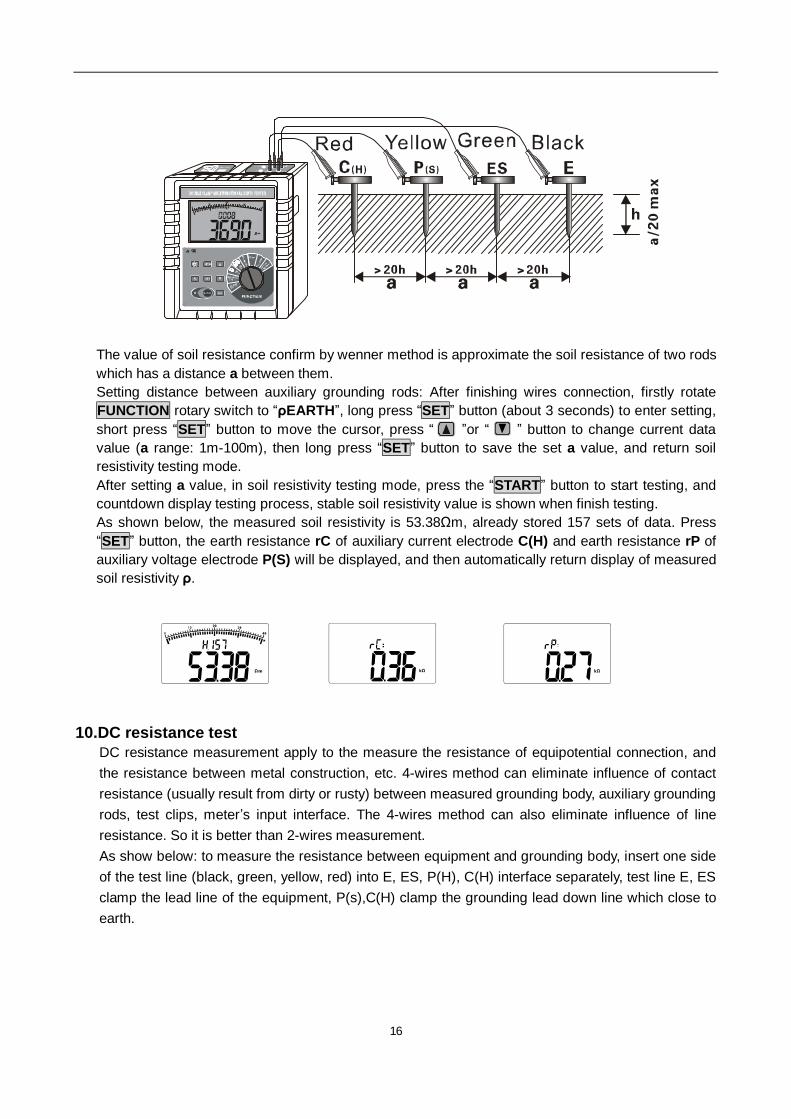
9.Soil Resistivity Measurement Soil resistivity ρ is a determining factor of grounding resistance of grounding body. Different nature of the soil, there is a different soil resistivity. Even the same kind of soil, due to different temperature and water content and so on; the soil resistivity will correspondingly have a significant change. Therefore, in order to have a correct basis in the design of the grounding device, ensure the designed grounding device be more in accord with the need of practical work, soil resistivity measurement is very essential. Soil resistivity is measured by 4-pole method (Wenner method) According to formula ρ=2πaR(Ωm) calculating soil resistivity ρ, its unit is Ωm, in which: a——electrode distance R——soil resistivity between electrode P(S)-ES 4-pole method (Wenner method): Connect testing wires as shown below, pay attention to the distance between auxiliary grounding rods, and the embedding depth. Respectively insert C(H), P(S), ES, E auxiliary grounding rods deep into the earth in a straight line, and then connect testing wires (red, yellow, green, black) corresponding to C(H), P(S), ES, E of interfaces and measured auxiliary grounding rods.
16
The value of soil resistance confirm by wenner method is approximate the soil resistance of two rods which has a distance a between them. Setting distance between auxiliary grounding rods: After finishing wires connection, firstly rotate FUNCTION rotary switch to “ρEARTH”, long press “SET” button (about 3 seconds) to enter setting, short press “SET” button to move the cursor, press “ ”or “ ” button to change current data value (a range: 1m-100m), then long press “SET” button to save the set a value, and return soil resistivity testing mode. After setting a value, in soil resistivity testing mode, press the “START” button to start testing, and countdown display testing process, stable soil resistivity value is shown when finish testing. As shown below, the measured soil resistivity is 53.38Ωm, already stored 157 sets of data. Press “SET” button, the earth resistance rC of auxiliary current electrode C(H) and earth resistance rP of auxiliary voltage electrode P(S) will be displayed, and then automatically return display of measured soil resistivity ρ.
10.DC resistance test DC resistance measurement apply to the measure the resistance of equipotential connection, and the resistance between metal construction, etc. 4-wires method can eliminate influence of contact resistance (usually result from dirty or rusty) between measured grounding body, auxiliary grounding rods, test clips, meter’s input interface. The 4-wires method can also eliminate influence of line resistance. So it is better than 2-wires measurement. As show below: to measure the resistance between equipment and grounding body, insert one side of the test line (black, green, yellow, red) into E, ES, P(H), C(H) interface separately, test line E, ES clamp the lead line of the equipment, P(s),C(H) clamp the grounding lead down line which close to earth.

17
When connection is done, rotate” FUNCTION“ switch to” ”, and press” START” button to enter resistance testing mode. During testing, display countdown and process bar indicator. Stable values shown on the screen is equipotential connection resistance R between equipment and grounding body when finish testing.
11.AC current measurement As the picture shows below, insert blue plug of CT2 into C1 interface, black plug insert into C2 interface, clamp the wires be measured with current clamp.
The current of the circuit be measured can’t exceed 600A, test by current clamp only, can’t input current signal to interface of meter directly; otherwise, meter may be damaged. During measure current, CT2 should be used, or there would error exist with the value When measuring load current, clamp the live wire (single) with current clamp; clamp live wire and null line together or clamp the grounding line when measure leakage current. Should avoid the interference of electromagnetic field when measuring leakage current.

18
When the connection of current clamp is done, rotate FUNCTION switch to “Iclamp”, enter current measurement mode, LCD display effective value directly, and bar chart indicate the change of amplitude
12.Earth Voltage Measurement Earth voltage measurement need to use one auxiliary grounding rod.
The meters connect with the earth only by testing wires and auxiliary grounding rods. Other testing wires of meter’s interface can’t connect with commercial power line L, N, otherwise may cause leakage, the breaker may start, it is dangerous. Earth voltage measurement can't exceed 100 V. Can’t be used for commercial voltage test, or the meter may be damaged
Earth voltage: That is a potential difference between zero potential differences and grounding equipment shell, grounding wires, grounding body when electrical equipment has a grounding fault. Earth voltage is the potential differences between the earths. As a reference point, the earth is zero potential. Earth voltage measurement needs one auxiliary grounding rod. Please pay attention to the difference from commercial AC voltage measurement. As shown below: meter, auxiliary grounding rods, testing wires are all connected, rotate FUNCTION rotary switch to “EARTH VOLTAGE” and start testing, LCD will display the test results.
13.Back light control After booting, press” ”button to turn on or off backlight. The backlight function is suitable to dark spot; power consumption of backlight is about 25mA. It will default backlight turn-off for each startup.
14.Alarm Settings After startup, rotate FUNCTION rotary switch to select function, press “ AL” button for a brief time to open or shut off alarm function, press“ AL” button for a long time (about 3 seconds) to enter alarm critical value settings, press “ ”or“ ” to change current digital, press “ AL” button to move cursor and then press “ AL” button to store and exit. When measurement value is larger than alarm critical settings value and it has opened alarm function, the tester will flash and display icon and give out “toot-toot-toot--”alarming sound.
15.Data Lock/Storage In test mode, press “MEM” button for a brief time to lock current displayed data, showing “HOLD”, “MEM” icon and automatically store with serial numbers. If storage is full, the tester will display “FULL” icon, and then press button to remove lock. As shown in the left figure below: the lock measurement data of soil resistivity is 53.38Ωm, as the

19
28th group of data storage.
16.Data Reading/Deletion In test mode, press “MEM” button for a longer time (over 3 seconds) to enter data reading, press “ ”or“ ” button to select reading data group number by step value 1, press“ ”or“ ”button constantly to select reading data group number by step value 10. When the current data is earth resistance or soil resistivity, press “SET” button to read data value of rC, rP and a, then press “MEM” button to exit from reading. On reading if there is no storage data, LCD will display “- - - -”, see the above right figure. Under data reading status, press “CLR” button to enter data deletion, press “ ”or“ ” to select “no” or “yES”, selecting “no” and then pressing “CLR” button for not deleting and return data reading status, selecting “yES” and then pressing “CLR” button for deleting stored data and it will show as above right figure after deletion. Notice: Operating data deletion will delete all the stored data one-time, and unable to be restored. Please careful operation.
17.Data Upload It is forbidden to connect to computer during testing; otherwise, earth voltage would destroy
computer or the instrument. The stored data can be uploaded to computer. Make good connection of computer with RS232 communication wire of the tester, switch on the tester and run monitoring software, and if the software displays that interface is open and the connection is successful, then it can read the stored historical data, upload to company and preserve. Monitoring software has the function of online real-time monitoring and historical inquiry, dynamic display, with alarm value settings and alarm indicator, and the function of historical data access, reading, preserve, print and other functions.
VII. Battery Replacement
Please don’t replace battery in flammable spot Please don’t replace battery during measurement Pay attention to battery polarity and specification, and don’t mix use of new and used battery to avoid damage on Tester When the enclosure of Tester is wet, please do not open battery cover Please put the used batteries in appointed collection place.
1. Switch off; making sure that the Tester is under switch-off state. 2. Loosen the four screws on battery cover at the bottom of the Tester, and open battery cover. 3. Replace new battery, pay attention to battery polarity and specification, close battery cover, and
fasten screw. 4. Switch on verification, otherwise re-operate.

20
Ⅷ. ACCESSORIES
Tester 1 PC Tester Bag 1 PC Auxiliary Grounding Rod 4 PCS Standard testing Wire 4 wires: each for red 20m, black 20m, yellow 10m, and green 10m Simple testing Wire 2 wires: each for red 1.6m and black 1.6m Current clamp 2PC Zinc-manganese Dry Battery 6 PCS(R14S 1.5V) Monitoring Software Disk 1 Copy RS232 Communication Cable 1 PC Manual/Warranty Card/Qualification Certificate 1 Copy

21
Manufactured by
ETCR Electronic Technology Company Address: F-3F, No.4 Pengshang Zhifu Road, Jiahe, Baiyun District, Guangzhou, Guangdong, China Post Code: 510440 Tel: (86-20)62199556 62199554 Fax: (86-20)61100822 E-mail: [email protected]