WARNING - American LandMaster
18
19146 Installation Guide, Commercial Signal Package with Brake & Tail Lights Page 1 of 18 Kit PN 18927-R – Commercial Signal Package with Tail Lights for Standard Cab Kit PN 18928-R – Commercial Signal Package with Tail Lights for Crew Cab 19146 Installation Guide, Commercial Signal Package SPECIAL REQUIREMENTS: This Guide covers Standard Cab and Crew Cab TOOLS REQUIRED ESTIMATED INSTALL TIME RECOMMENDED SKILL LEVEL 1/2” Wrench 3/16” Drill bit and Drill 3 Hours Intermediate 1/2” Socket & Ratchet Wire Cutters 4 mm Allen Wrench 1” Hole Saw Before you begin, check the contents of the kit against the parts list below. Immediately contact American Landmaster with any questions or discrepancies. American Landmaster cannot assume responsibility for any damage or injury resulting from incorrect installation of parts. American Landmaster suggests that accessory kits be installed by an authorized American Landmaster dealer or service center. !! WARNING !! Serious Injury or death could occur! • Use proper personal protective equipment during installation of this kit. Use safety glasses. (1) Backup Switch (1) Brake Switch (1) Electric Horn (12) #10 Screw (2) Tail Lights (4) 5/16” X 2.0” Bolts (1) Backup Alarm (12) #10 Nuts (2) Tail Light Brackets (6) 5/16” Lock Nut (2) 5/16” X 1.5” Bolts (1) Red Horn Switch (1) Brake Switch Bracket (1) Backup Switch Bracket (20) Zip Ties (1) Electrical Harness (1) Strobe Light Kit (1) 1” Split Grommet Note: For vehicles with a FLIP SEAT, Kit part number 19305 must be purchased and installed with this kit. ASSEMBLY INSTRUCTIONS: Here is the instructional video: In Process PARTS LIST FOR AMERICAN LANDMASTER ACCESSORY KIT
Transcript of WARNING - American LandMaster

19146 Installation Guide, Commercial Signal Package with Brake & Tail Lights Page 1 of 18
Kit PN 18927-R – Commercial Signal Package with Tail Lights for Standard Cab
Kit PN 18928-R – Commercial Signal Package with Tail Lights for Crew Cab
19146 Installation Guide, Commercial Signal Package
SPECIAL REQUIREMENTS: This Guide covers Standard Cab and Crew Cab
TOOLS REQUIRED ESTIMATED INSTALL TIME
RECOMMENDED SKILL LEVEL
1/2” Wrench 3/16” Drill bit and Drill 3 Hours Intermediate
1/2” Socket & Ratchet Wire Cutters
4 mm Allen Wrench 1” Hole Saw
Before you begin, check the contents of the kit against the parts list below. Immediately contact American Landmaster with any questions or
discrepancies. American Landmaster cannot assume responsibility for any damage or injury resulting from incorrect installation of parts. American
Landmaster suggests that accessory kits be installed by an authorized American Landmaster dealer or service center.
!! WARNING !! Serious Injury or death could occur!
• Use proper personal protective equipment during installation of this kit. Use safety glasses.
(1) Backup Switch (1) Brake Switch (1) Electric Horn (12) #10 Screw
(2) Tail Lights (4) 5/16” X 2.0” Bolts (1) Backup Alarm (12) #10 Nuts
(2) Tail Light Brackets (6) 5/16” Lock Nut (2) 5/16” X 1.5” Bolts (1) Red Horn Switch
(1) Brake Switch Bracket (1) Backup Switch Bracket (20) Zip Ties (1) Electrical Harness
(1) Strobe Light Kit (1) 1” Split Grommet
Note: For vehicles with a FLIP SEAT, Kit part number 19305 must be purchased and installed with this kit.
ASSEMBLY INSTRUCTIONS:
Here is the instructional video: In Process
PARTS LIST FOR AMERICAN LANDMASTER ACCESSORY KIT

19146 Installation Guide, Commercial Signal Package with Brake & Tail Lights Page 2 of 18
Figure 1 – Kit contents – Commercial Signal Package
Note: Parts are shown pre-assembled for reference. Parts in kit will require assembly.
Figure 2 – Backup Alarm Bracket (Not used with Flip Seat)
Preliminary Dis-Assembly Instructions:
1- Remove the hood. Remove three screws from each front fender and two screws from the front hood using the 4 mm
Allen wrench. Lift the hood off and set aside. If the vehicle has turn signals, disconnect the amber lights by depressing
the release tab on each turn signal lamp connector and pull apart. Set the hood aside where it will not be damaged.

19146 Installation Guide, Commercial Signal Package with Brake & Tail Lights Page 3 of 18
Figure 3: Removing Three Fender Fasteners Figure 4: Removing Two Hood Fasteners
2- Remove the Black Instrument panel cover. Unscrew each stainless steel fastener that holds down the black instrument
panel cover using a 4 millimeter Allen wrench. Place the fasteners in a small container so they do not get lost. Lift the
cover straight up and off the panel. Set the cover aside where it will not get damaged.
Figure 5: Removing Black Instrument Panel Cover
3- Remove the tunnel cover. Remove 8 bolts from the cab top side using a 3/16” socket. Clamp nuts are used for easy
removal and installation. If you have a crew cab, remove the rear tunnel cover as well.
Black Instrument
Panel cover

19146 Installation Guide, Commercial Signal Package with Brake & Tail Lights Page 4 of 18
Figure 6: Tunnel Cover Installed Figure 7: Tunnel Cover Removed
4- Remove the driver seat.
5- Lift up on the front of the seat to remove. Lift the seat up and out of the vehicle. Set it aside in a safe place. Do not place
the seat next to sharp surfaces that could puncture the covering.
6- Remove the Front Brake System Cover
Use a flat screwdriver and pry the two clam shells apart. Getting the right half off is difficult. Rock the upper top side to
the right and roll it down to remove. You will not reinstall this shell.
Figure 8: Brake System Clam shell housing Figure 9: Brake System clam shell removed
19146 Installation Guide, Commercial Signal Package with Brake & Tail Lights Page 5 of 18
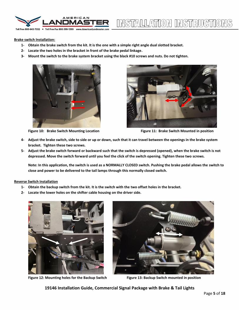
Brake switch Installation:
1- Obtain the brake switch from the kit. It is the one with a simple right angle dual slotted bracket.
2- Locate the two holes in the bracket in front of the brake pedal linkage.
3- Mount the switch to the brake system bracket using the black #10 screws and nuts. Do not tighten.
Figure 10: Brake Switch Mounting Location Figure 11: Brake Switch Mounted in position
4- Adjust the brake switch, side to side or up or down, such that it can travel between the openings in the brake system
bracket. Tighten these two screws.
5- Adjust the brake switch forward or backward such that the switch is depressed (opened), when the brake switch is not
depressed. Move the switch forward until you feel the click of the switch opening. Tighten these two screws.
Note: In this application, the switch is used as a NORMALLY CLOSED switch. Pushing the brake pedal allows the switch to
close and power to be delivered to the tail lamps through this normally closed switch.
Reverse Switch Installation
1- Obtain the backup switch from the kit. It is the switch with the two offset holes in the bracket.
2- Locate the lower holes on the shifter cable housing on the driver side.
Figure 12: Mounting holes for the Backup Switch Figure 13: Backup Switch mounted in position

19146 Installation Guide, Commercial Signal Package with Brake & Tail Lights Page 6 of 18
3- Mount the switch and bracket to the shifter housing using the two black #10 screws and nuts. Do not tighten. The switch
will be inside the housing and directly in from of the gear shifter linkage.
4- Place the vehicle in Reverse.
5- Adjust the backup alarm switch forward or backward such that the switch is depressed (closed), when the vehicle is in
Reverse. Move the switch forward until you feel the click of the switch closing while in the reverse gear. Tighten all four
screws. When the vehicle is in Neutral, the switch must be open (not depressed).
Note: In this application, the switch is used as a NORMALLY OPEN switch. Placing the vehicle in Reverse allows the power
to be delivered to the backup alarm through this switch when it is closed.
Note: This single plunger switch contains both NORMALLY OPEN and NORMALLY CLOSED contacts. Different switch
contacts are used based upon the feature through the harness connections, i.e. pins 1 and 5 are normally open for the
backup switch and pins 4 and 8 are normally closed for the brake switch.
Electric Horn Installation:
1- Obtain the electric trumpet horn from the kit.
2- Use the 5/16” by ¾” long bolt to attach the horn to this location on the frame.
3- Attach the horn to the center of the instrument panel bracket as shown below.
4- The Horn should be parallel to the ground. Tighten the bolt to secure.
5- The horn trumpet must point down. If it is mounted facing up, it will fill with water and fail.
Figure 14: Mounting location for the Electric Horn Figure 15: Proper Mounting Orientation
Strobe Light Installation
1- The strobe light shall be mounted on the flat spot in the front and center of the roof. Use the foam gasket from the
strobe light as a template for drilling two holes in the roof. Use a 3/16” bit and drill two holes for mounting the strobe.

19146 Installation Guide, Commercial Signal Package with Brake & Tail Lights Page 7 of 18
Figure 16: Mounting Area for the Strobe Light Figure 17: Using the Strobe Gasket as a Template
2- Mount the strobe light to the roof with the screws provided with the light. Mount with the wire harness facing rearward.
3- Using a 1 inch hole saw, drill a hole near the light’s wire harness.
Figure 18: Strobe Light Mounted to the Roof Figure 19: 1” Hole Drilled for the Harness
4- Attach the split grommet from the kit over the strobe light harness. Ensure that the beveled edge of the grommet is
closest to the roof hole.
5- Feed the connector and harness through the hole in the roof.
6- Using a flat screw driver and start the grommet into the hole, starting at the split.
7- Keep pressing the grommet into the hole until fully seated.

19146 Installation Guide, Commercial Signal Package with Brake & Tail Lights Page 8 of 18
Figure 20: Grommet attached to the Strobe Light harness Figure 21: Grommet seated into the Roof
NOTE: The following two sections apply to both the polyvinyl bed and the steel bed for rear lighting and backup alarm
installation. If you have a FLIP SEAT bed, skip to the section titled “FLIP SEAT Lighting and Alarm Installation”.
Tail Lamp Installation:
1. Locate the two tail light assemblies from the kit and the four 1.5 inch long carriage bolts and nuts.
2. Each lamp is attached to the tail light bracket with black #10 screws and nuts.
3. Tilt the bed up. Locate the two holes on each side of the back rail to mount the tail lights.
4. Mount a lamp assembly on each end of the rear rail. Use a half inch socket to tighten.
Figure 22: Location for Mounting Tail Lights Figure 23: Tail Lights Mounted
Backup Alarm Installation:
1. Locate backup alarm and the mounting bracket from the kit.
2. Mount the backup alarm on the right side of the bracket as shown below using the M6 fasteners.
3. Place the bracket with the alarm on the rear diagonal of the frame tubes in a level manner.
4. Insert the two 2” carriage bolts through the holes in the end of the bracket and tighten securely.

19146 Installation Guide, Commercial Signal Package with Brake & Tail Lights Page 9 of 18
Figure 24: Backup alarm Mounted to the Vehicle
FLIP SEAT Lighting and Alarm Installation
1- For vehicles equipped with a rear flip seat bed, the tail lamps are mounted on the rear Upper B pillar tube rails using a
pair of P clamps found in KIT 19305. Attach each tail light as shown below to the vertical rail using two 1.75” inch P
clamps and four black ¼” by 1 inch bolts provided in the kit.
Figure 25: Tail Lights Mounted on Upper Cab Rails for Flip Seat

19146 Installation Guide, Commercial Signal Package with Brake & Tail Lights Page 10 of 18
2- Mount the backup alarm using two 1.25” P Clamps and a pair of ¼” by 1 inch bolts with lock nuts from the 19305 kit.
Figure 26: Backup Alarm Mounted on Upper Seat Rail
Note: All electrical components are now mounted for this feature and next the wire harness must be installed.
Commercial Harness Installation for the Forward Portion:
1- Start the harness installation by laying the harness on the front cab tunnel with the green four pin connector and other
associated connectors positioned forward toward the dash panel.
2- First, route the forward portion of the harness through the dash panel and up to the instrument panel harness.
3- Locate the green connector on the instrument panel harness and remove the black cap by depressing the release tab on
the green connector. DO NOT PULL THE CAP OFF BY PULLING ON THE WIRES. USE ONE HAND ON EACH CONNECTOR
HALF.
Figure 27: Harness ready to install starting at cab tunnel Figure 28: Locate Green Connector on Main IP Harness
4- Connect the green connector of the Commercial harness to the green connector of the instrument panel harness.

19146 Installation Guide, Commercial Signal Package with Brake & Tail Lights Page 11 of 18
5- Route the black horn switch connector and the black eight pin brake switch connector over to the right towards the
driver side of the instrument panel.
6- Route the harness up and over the frame tube that arches over the steering shaft tubes. Loosely tie wrap.
7- Connect the horn connector to the red horn switch. Be sure to attach the connector with the latch lining up with the
hook on the switch. The hook is on the lower side of the switch. Place one hand on the front of the switch while mating
the harness connector with the other.
Figure 29: Correct Harness Orientation to the Switch Figure 30: Horn Switch Hooked Up
8- Route the black 8 pin connector down the driver side frame tube and connect it to the brake switch.
9- Loosely tie wrap the harness to the frame tubes about every 12 inches.
Figure 31: Commercial Harness Routed on the Front
10- Route the second black eight pin connector to the reverse switch in the center of the panel. Connect to the reverse
switch.
11- Route the gray two pin connector that will mate to the electric horn. Connect to the horn. Tie wrap horn harness to the
horn bracket.
Hook Latch

19146 Installation Guide, Commercial Signal Package with Brake & Tail Lights Page 12 of 18
Figure 32: Backup Switch hooked up to the Harness
Tie wrap the harness about every 12 inches to frame tubes. Tighten all tie wraps and cut off the extra tails with a wire cutters.
Strobe Light Switch and Harness Installation:
1- Locate the black 10 pin connector with a label of STROBE on it. This is for a Strobe Light Switch provided with the kit.
2- This connector will have a one wire jumper installed between pins 2 and 3 to provide strobe light operation with KEY ON.
If that is the functionality that is desired, then leave the jumper in place. Do not use the strobe light switch from the kit.
3- If strobe light operation with a dash mounted switch is desired, then remove the jumper and follow the steps below.
4- Remove an available switch blank from the bank of the seven switches plate. Push the blank out from the back of the
plate.
5- Insert the Strobe Light rocker switch into the open spot. Push the switch into the hole until it clicks into position.
Figure 33: Seven Switch Plate in Instrument Panel Figure 34: Seven Switch Plate with Strobe Light Switch Added
6- Plug the Strobe Light Switch harness onto the strobe light switch. Ensure proper switch to harness connector orientation
as described before with the horn switch connector above.
19146 Installation Guide, Commercial Signal Package with Brake & Tail Lights Page 13 of 18
Figure 35: Strobe Light Harness attached to the switch
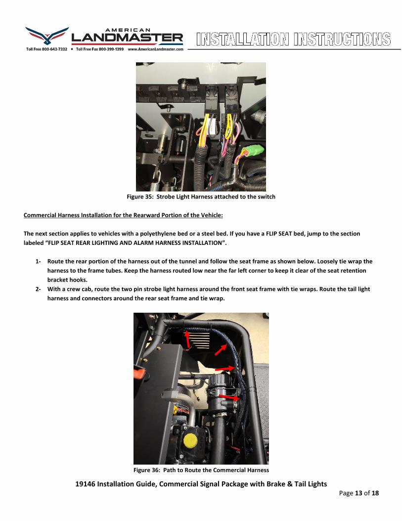
Commercial Harness Installation for the Rearward Portion of the Vehicle:
The next section applies to vehicles with a polyethylene bed or a steel bed. If you have a FLIP SEAT bed, jump to the section
labeled “FLIP SEAT REAR LIGHTING AND ALARM HARNESS INSTALLATION”.
1- Route the rear portion of the harness out of the tunnel and follow the seat frame as shown below. Loosely tie wrap the
harness to the frame tubes. Keep the harness routed low near the far left corner to keep it clear of the seat retention
bracket hooks.
2- With a crew cab, route the two pin strobe light harness around the front seat frame with tie wraps. Route the tail light
harness and connectors around the rear seat frame and tie wrap.
Figure 36: Path to Route the Commercial Harness

19146 Installation Guide, Commercial Signal Package with Brake & Tail Lights Page 14 of 18
3- Continue routing the tail light harness toward the rear of the vehicle.
4- Route under the seat frame and continue along the outer frame tube for the fender supports.
5- Tie wrap loosely about every 12 inches
Figure 37: Tail Light Harness routed along outer frame Figure 38: Harness Routed through the Pivot Point
6- Feed the harness past the bed pivot point and tie wrap again.
7- Attach the black two pin connector to the backup alarm.
8- Route the shorter tail light connector to the driver side light. Install the connector on the lamp until it clicks.
9- Route the longer tail light connector to the passenger side light. Install the connector on the lamp until it clicks.
10- Locate the ¼” holes in the bed frame for installing Christmas tree tie wraps which are provided on the harness.
Figure 39: Sample Christmas tree Tie Wrap Hole Locations Figure 40: Tail Light Harness Connection
11- Starting at each tail light, route and clip the harness to the frame with the Christmas tree tie wraps that are on the
harness using the holes in the frame.
Backup Alarm Connector

19146 Installation Guide, Commercial Signal Package with Brake & Tail Lights Page 15 of 18
12- Back up and continue clipping the harness to the frame until you get back to the pivot point.
13- The polyethylene bed is smaller than the steel bed so there will be some extra harness length with the poly bed. Use
your best judgement to hank up and use standard tie wraps on the extra length. Be sure to leave enough length to
prevent stress on the harness when the bed is tilted.
Figure 41: Tail Light Wiring Routing and Clipping on a Poly Bed
14- The gray two pin strobe light harness break out will be found near the rearward position of the driver seat side rail.
15- Remove the driver side screw that holds the back plastic seat surround cover in place. Pull the end of the cover back and
away from its position.
16- Cut off a one inch square piece from the upper right corner of the surround as shown below with a carpet knife or other
cutting tool. Later models will have the surround pre-cut.
17- Reinstall the seat surround and fasten with the screw.
Figure 42: One inch square section of the surround cut out
18- Route the gray two pin connector and harness under the rail at the back of the driver seat frame. Take it up the front of
the driver side B pillar on the seat frame.

19146 Installation Guide, Commercial Signal Package with Brake & Tail Lights Page 16 of 18
Figure 43: Routed Along Side Rail Figure 44: Route under the Side Tube Figure 45: Route up the B Pillar
19- Route the harness along the top driver side tube rail and then to the middle of the roof by following the front roof rail.
20- Connect the two pin gray connector to the Strobe Light connector.
21- Starting at the strobe light connector, tie wrap the mated connector pair to the front roof rail as shown.
22- Tie wrap as necessary backing up along the upper side rail and to the rear B Pillar. Tighten the wraps as you go and cut
off the tails with the wire cutters.
23- Arrange and route the harness going down the B pillar and around the seat frame. Tighten the wraps as you go and cut
off the tails with the wire cutters.
Figure 46: Route and Clip Along the Driver Side Upper Rail
Commercial Harness Installation for the Crew Cab
1- The Commercial harness on the crew cab is installed in exactly the same manner as the above listed standard cab
procedure, except that the rearward portion of the harness is routed to the rear seat before it is attached to the fender
frame and dump bed.
2- The strobe light harness is routed and clipped to the front seat frame.
3- The crew cab kit is a different part number with a longer harness but same components.

19146 Installation Guide, Commercial Signal Package with Brake & Tail Lights Page 17 of 18
FLIP SEAT REAR LIGHTING AND ALARM HARNESS INSTALLATION
1- Route the rear portion of the harness along the side seat frame and under the rail at the back. Take it up the front of the
driver side B pillar on the outside of the seat frame. Route the harness end behind the seat at the upper seat back tube.
Figure 47: Routed Along Side Rail Figure 48: Route under the Side Tube Figure 49: Route up the B Pillar
2- Route the harness under the upper seat back rail.
3- Make connection to each tail light and to the Backup Alarm.
4- Tie wrap the harness to the rails about every 12 inches.
Figure 50: Harness Routed across upper seat back rail
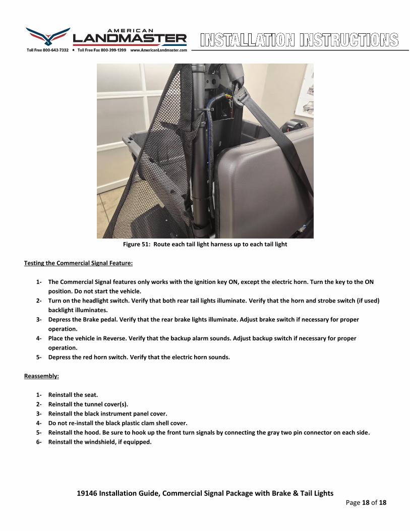
5- Route each tail light harness up to the tail light and plug in the harness until it clicks.
6- Tie wrap each harness about every 12 inches. Use wire cutters to cut off the extra tails.
19146 Installation Guide, Commercial Signal Package with Brake & Tail Lights Page 18 of 18
Figure 51: Route each tail light harness up to each tail light
Testing the Commercial Signal Feature:
1- The Commercial Signal features only works with the ignition key ON, except the electric horn. Turn the key to the ON
position. Do not start the vehicle.
2- Turn on the headlight switch. Verify that both rear tail lights illuminate. Verify that the horn and strobe switch (if used)
backlight illuminates.
3- Depress the Brake pedal. Verify that the rear brake lights illuminate. Adjust brake switch if necessary for proper
operation.
4- Place the vehicle in Reverse. Verify that the backup alarm sounds. Adjust backup switch if necessary for proper
operation.
5- Depress the red horn switch. Verify that the electric horn sounds.
Reassembly:
1- Reinstall the seat.
2- Reinstall the tunnel cover(s).
3- Reinstall the black instrument panel cover.
4- Do not re-install the black plastic clam shell cover.
5- Reinstall the hood. Be sure to hook up the front turn signals by connecting the gray two pin connector on each side.
6- Reinstall the windshield, if equipped.