WAN Aggregator QoS Design - cisco.com · (T1/E1 links) where serialization delays ordinarily woul d...
50
CHAPTER 3-1 Enterprise QoS Solution Reference Network Design Guide Version 3.3 3 WAN Aggregator QoS Design Note This content has been updated. The latest validated designs are published in the Cisco Press book End-to-End QoS Network Design: Quality of Service for Rich-Media & Cloud Networks, 2nd Edition available at: http://www.ciscopress.com/store/end-to-end-qos-network-design-quality-of-service-for-978158714369 4. This chapter discusses WAN QoS considerations and designs, including the following: • Slow-speed (≤ 768 kbps) WAN link design • Medium-speed (768 kbps to T1/E1 speed) WAN link design • High-speed (> T1/E1 speed) WAN link design Additionally, these designs are applied to specific Layer 2 WAN media, including the following: • Leased lines • Frame Relay • ATM • ATM-to-Frame Relay Service Interworking • ISDN A fundamental principle of economics states that the more scarce a resource is the more efficiently it should be managed. In an enterprise network infrastructure, bandwidth is the prime resource and also is the scarcest (and, likewise, most expensive) over the WAN. Therefore, the case for efficient bandwidth optimization using QoS technologies is strongest over the WAN, especially for enterprises that are converging their voice, video, and data networks. The design principles described in this chapter apply primarily to Layer 2 WANs, such as leased lines, Frame Relay, and ATM (including ATM-to-Frame Relay Service Interworking). However, many service providers use these Layer 2 WAN technologies to access Layer 3 VPN services. Therefore, many of the design principles and examples presented in this chapter also apply to such VPN access scenarios. This chapter provides design guidance for enabling QoS over the WAN. It is important to note that the recommendations in this chapter are not autonomous. They are critically dependent on the recommendations discussed in Chapter 2, “Campus QoS Design.”
Transcript of WAN Aggregator QoS Design - cisco.com · (T1/E1 links) where serialization delays ordinarily woul d...

EnterprVersion 3.3
C H A P T E R 3
WAN Aggregator QoS DesignNote This content has been updated. The latest validated designs are published in the Cisco Press book End-to-End QoS Network Design: Quality of Service for Rich-Media & Cloud Networks, 2nd Edition available at: http://www.ciscopress.com/store/end-to-end-qos-network-design-quality-of-service-for-9781587143694.
This chapter discusses WAN QoS considerations and designs, including the following:
• Slow-speed (≤ 768 kbps) WAN link design
• Medium-speed (768 kbps to T1/E1 speed) WAN link design
• High-speed (> T1/E1 speed) WAN link design
Additionally, these designs are applied to specific Layer 2 WAN media, including the following:
• Leased lines
• Frame Relay
• ATM
• ATM-to-Frame Relay Service Interworking
• ISDN
A fundamental principle of economics states that the more scarce a resource is the more efficiently it should be managed. In an enterprise network infrastructure, bandwidth is the prime resource and also is the scarcest (and, likewise, most expensive) over the WAN. Therefore, the case for efficient bandwidth optimization using QoS technologies is strongest over the WAN, especially for enterprises that are converging their voice, video, and data networks.
The design principles described in this chapter apply primarily to Layer 2 WANs, such as leased lines, Frame Relay, and ATM (including ATM-to-Frame Relay Service Interworking). However, many service providers use these Layer 2 WAN technologies to access Layer 3 VPN services. Therefore, many of the design principles and examples presented in this chapter also apply to such VPN access scenarios.
This chapter provides design guidance for enabling QoS over the WAN. It is important to note that the recommendations in this chapter are not autonomous. They are critically dependent on the recommendations discussed in Chapter 2, “Campus QoS Design.”
3-1ise QoS Solution Reference Network Design Guide

Chapter 3 WAN Aggregator QoS Design Where Is QoS Needed over the WAN?
Where Is QoS Needed over the WAN?Within typical WAN environments, routers play one of two roles: a WAN aggregator or a branch router. In some very complex WAN models, enterprises might have distributed WAN aggregators to cover regional branches, but the role of such middle-tier routers is not significantly different from that of a WAN aggregator located at a campus edge. This chapter focuses on WAN edge recommendations—primarily for WAN aggregator routers, but these correspondingly apply to the WAN edge designs of branch routers. QoS policies required on WAN edges are shown in Figure 3-1.
Figure 3-1 Where is QoS Needed over the WAN?
WAN Aggregator
WAN Edges
CampusDistributionSwitches
LAN Edges
Queuing/Dropping/Shaping/Link-Efficiency Policies forCampus-to-Branch Traffic
WAN
2248
30
WAN Edge QoS Design ConsiderationsQoS policies required on WAN aggregators include queuing, shaping, selective dropping, and link-efficiency policies in the outbound direction of the WAN link. Traffic is assumed to be correctly classified and marked (at Layer 3) before WAN aggregator ingress. Remember, Layer 3 markings (preferably DSCP) are media independent and traverse the WAN media, whereas Layer 2 CoS is lost when the media switches from Ethernet to WAN media.
Several factors must be kept in mind when designing and deploying QoS polices on WAN edges. Some of these considerations were introduced in earlier chapters. They are re-emphasized here to underscore their importance to the context of the WAN QoS designs that follow.
Software QoSUnlike LAN (Catalyst) queuing, which is done in hardware, WAN edge QoS is performed within Cisco IOS Software. If the WAN aggregator is homing several hundred remote branches, the collective CPU required to administer complex QoS policies might be more than some older devices can provide.
The main point to keep in mind is that QoS entails a marginal CPU load. WAN topologies and QoS policies should be designed to limit the average CPU utilization of the WAN aggregator to 75 percent (or lower) because this leaves cycles available to respond efficiently to routing updates.
3-2Enterprise QoS Solution Reference Network Design Guide
Version 3.3

Chapter 3 WAN Aggregator QoS DesignWAN Edge QoS Design Considerations
Bandwidth Provisioning for Best-Effort TrafficAs discussed previously, the Best-Effort class is the default class for all data traffic. Only if an application has been selected for preferential or deferential treatment is it removed from the default class. Because many enterprises have several hundreds, if not thousands, of data applications running over their networks, adequate bandwidth must be provisioned for this class as a whole to handle the sheer volume of applications that default to it. It is recommended that at least 25 percent of a WAN link’s bandwidth be reserved for the default Best-Effort class.
Bandwidth Provisioning for Real-Time TrafficNot only does the Best-Effort class of traffic require special bandwidth-provisioning consideration, but the Real-Time class does as well. The amount of bandwidth assigned to the Real-Time class is variable; however, if too much traffic is assigned to Real-Time (strict-priority/low-latency) queuing, the overall effect is a dampening of QoS functionality for data applications.
The goal of convergence cannot be overemphasized: to enable voice, video, and data to coexist transparently on a single network. When real-time applications (such as voice or interactive-video) dominate a WAN link, data applications fluctuate significantly in their response times, destroying the transparency of the “converged” network.
Cisco Technical Marketing testing has shown a significant decrease in data application response times when Real-Time traffic exceeds one-third of a link’s bandwidth capacity. Cisco IOS Software allows the abstraction (and, thus, configuration) of multiple LLQs. Extensive testing and production-network customer deployments have shown that limiting the sum of all LLQs to 33 percent is a conservative and safe design ratio for merging real-time applications with data applications.
Furthermore, it should be kept in mind that if VoIP traffic is set to dominate a link via low-latency queuing (which is essentially strict-priority FIFO queuing), VoIP actually could negatively impact other VoIP traffic because of extensive FIFO queuing. This easily could result in excessive serialization delays (Š 10 ms per hop) on even medium-speed links (T1/E1 links) where serialization delays ordinarily would not even be a consideration. (Serialization delays are discussed in more detail in the next section.) Such excessive serialization delays from VoIP LLQ overprovisioning would increase VoIP jitter and, thus, decrease overall call quality.
Note The 33-percent limit for the sum of all LLQs is simply a best-practice design recommendation; it is not a mandate. In some cases, specific business objectives cannot be met while holding to this recommendation. In such cases, enterprises must provision according to their detailed requirements and constraints. However, it is important to recognize the trade-offs involved with overprovisioning LLQ traffic in respect to the negative performance impact on data application response times.
SerializationSerialization delay refers to the finite amount of time it takes to clock a frame onto the physical media. Within the campus, this time is so infinitesimal that it is completely immaterial. Over the WAN, however, lower link speeds can cause sufficient serialization delay to adversely affect real-time streams, such as Voice or Interactive-Video.
Serialization delays are variable because they depend not only on the line rate of the link speed, but also on the size of the packet being serialized. Variable (network) delay also is known as jitter. Because the end-to-end one-way jitter target has been set as 30 ms, the typical per-hop serialization delay target is
3-3Enterprise QoS Solution Reference Network Design Guide
Version 3.3

Chapter 3 WAN Aggregator QoS Design WAN Edge QoS Design Considerations
10 ms (which allows for up to three intermediate hops per direction of VoIP traffic flow). This 10 ms per-hop target leads to the recommendation that a link fragmentation and interleaving (LFI) tool (either MLP LFI or FRF.12) be enabled on links with speeds at or below 768 kbps (this is because the serialization delay of a maximum-size Ethernet packet—1500 bytes—takes more than 10 ms to serialize at 768 kbps and below). Naturally, LFI tools need to be enabled on both ends of the link.
When deploying LFI tools, it is recommended that the LFI tools be enabled during a scheduled downtime. Assuming that the network administrator is within the enterprise’s campus, it is recommended that LFI be enabled on the branch router first (which is on the far end of the WAN link) because this generally takes the WAN link down. Then the administrator can enable LFI on the WAN aggregator (the near end of the WAN link), and the link will come back up. Otherwise, if the administrator enables LFI on the WAN aggregator first, the link will go down, along with any in-band management access to the branch router. In such a case, the administrator would need to remove LFI from the WAN aggregator (bringing the link back up), enable LFI on the branch router, and then re-enable LFI on the WAN aggregator.
Additionally, since traffic assigned to the LLQ escapes fragmentation, it is recommended that Interactive-Video not be deployed on slow-speed links; the large Interactive-Video packets (such as 1500-byte full-motion I-Frames) could cause serialization delays for smaller Interactive-Video packets. Interactive-Video traffic patterns and network requirements are overviewed in Chapter 2, “Campus QoS Design.”
IP RTP Header CompressionCompressing IP, UDP, and RTP headers (cRTP) for VoIP calls can result in significant bandwidth gains over WAN links. However, it is important to realize that cRTP is one of the most CPU-intensive features within the Cisco IOS Software QoS toolset. Therefore, it is recommended that cRTP be used primarily on slow-speed (≤ 768 kbps) links with a careful eye on CPU levels (especially for WAN aggregators that home a large number of remote branches).
Tx-ring TuningNewer versions of Cisco IOS Software automatically size the final interface output buffer (Tx-ring) to optimal lengths for Real-Time applications, such as Voice or Video. On some older versions of Cisco IOS Software, Tx-rings might need to be reduced on slow-speed links to avoid excessive serialization delay.
To determine the value of the Tx-ring on an interface, use the variation of the show controllers command shown in Example 3-1.
Example 3-1 Displaying the Tx-ring Value with the show controllers Command
WAG-7206-Left#show controllers Serial 1/0 | include tx_limitedtx_underrun_err=0, tx_soft_underrun_err=0, tx_limited=1(64)WAG-7206-Left#
The value within the parentheses following the tx_limited keyword reflects the value of the Tx-ring. In this particular example, the Tx-ring is set to 64 packets. This value can be tuned to the recommended setting of 3 on T1/E1 (or slower) links using the command shown in Example 3-2.
Example 3-2 Tuning the Tx-ring
WAG-7206-Left(config)#interface Serial 1/0
3-4Enterprise QoS Solution Reference Network Design Guide
Version 3.3

Chapter 3 WAN Aggregator QoS DesignWAN Edge QoS Design Considerations
WAG-7206-Left(config-if)#tx-ring-limit 3
The new setting quickly can be verified with the same show controllers command, as shown in Example 3-3.
Example 3-3 Verifying Tx-ring Changes
WAG-7206-Left#show controllers ser 1/0 | include tx_limitedTx_underrun_err=0, tx-soft-underru_rr=0, tx-limited=1(3)WAG-7206_Left#
Note In ATM, the length of the Tx-ring is defined in (576-byte) particles, not packets, and is tuned on a per-PVC basis. On some non-ATM interfaces, the Tx-ring even can be tuned to a minimum of 1 (packet). In either case, the Tx-ring can be tuned (on ≤ 768 kbps links) to approximately 1500 bytes, which is the MTU of Ethernet.
PAK_priorityPAK_priority is the internal Cisco IOS mechanism for protecting routing and control traffic. The design implications of PAK_priority are summarized in the following list:
• Layer 2 and Layer 3 control traffic on moderately congested WAN links typically is protected adequately with the default PAK_priority treatment within the router and the IP ToS byte markings of IPP6/CS6.
• On heavily congested links, it might be necessary to explicitly provision a CBWFQ bandwidth class for routing/control traffic, as identified by either IPP or CS6.
• Although IS-IS traffic receives PAK_priority within the router, it cannot be marked to IPP6/CS6 because IS-IS uses a CLNS protocol. (It does not use IP, so there are no IPP or DSCP fields to mark.) This is important to keep in mind if explicit bandwidth provisioning is required for IS-IS traffic because it cannot be matched against IPP6/CS6 like most other IGPs. However, NBAR can be used within a class map to match IS-IS traffic (for example, match protocol clns_is).
• Although BGPs (both eBGPs and iBGPs) are marked to IPP6/CS6, they do not receive PAK_priority treatment within the routers. Therefore, it may be necessary to provision a separate bandwidth class to protect BGP sessions, even on moderately congested links where the underlying IGPs are stable.
• On Catalyst 6500 switches running Cisco IOS Software on both the supervisors and MSFC, IGP packets marked internally with PAK_priority additionally are marked with IPP6/CS6 and the Layer 2 CoS value of 6. This is because scheduling and congestion avoidance within Cisco Catalyst switches is performed against Layer 2 CoS values.
Link SpeedsIn the context of WAN links, there are three main groupings of link speeds. These link speeds and their respective design implications are summarized in the following list:
• Slow (link speed ≤ 768 kbps):
– Deployment of Interactive-Video generally is not recommended on these links because of serialization implications.
– These links require LFI to be enabled if VoIP is to be deployed over them.
3-5Enterprise QoS Solution Reference Network Design Guide
Version 3.3
Chapter 3 WAN Aggregator QoS Design WAN Edge Classification and Provisioning Models
– cRTP is recommended (with a watchful eye on CPU levels).
– Check Tx-ring sizes (especially on slow-speed ATM PVCs); tune to 3, if needed.
– Three- to five-class traffic models are recommended.
• Medium (768 kbps ≤ link speed ≤ T1/E1):
– VoIP or Interactive-Video can be assigned to the LLQ (usually, there is not enough bandwidth to do both and still keep the LLQ provisioned at less than 33 percent—alternatively, Interactive-Video can be placed in a CBWFQ queue).
– LFI is not required.
– cRTP is optional.
– Three- to five-class traffic models are recommended.
• High (Š T1/E1 link speeds):
– LFI is not required.
– cRTP generally is not recommended (because the cost of increased CPU levels typically offsets the benefits of the amount of bandwidth saved).
– Five- to 11-class traffic models are recommended.
Distributed Platform QoS and Consistent QoS BehaviorIt is important to keep in mind that minor differences might exist between QoS configurations on distributed platforms (such as the Cisco 7500 series with VIPs) and those on nondistributed platforms (such as the Cisco 7200 or 1700). The most common difference is the inclusion of the distributed keyword after commands such as ip cef on distributed platforms. Where more complicated differences exist, they are highlighted explicitly in this chapter.
An important initiative is under way within Cisco to port the QoS code from the Cisco 7500 series routers to the nondistributed router families. This initiative is called Consistent QoS Behavior and has as its objectives simplifying QoS and increasing QoS consistency between platforms. Consistent QoS Behavior code should remove most, if not all, configuration idiosyncrasies between distributed and nondistributed platforms.
WAN Edge Classification and Provisioning ModelsOne of the most common questions raised when planning a QoS deployment over the WAN is “How many classes of traffic should be provisioned for?” The following considerations should be kept in mind when arriving at an appropriate traffic class model for a given enterprise.
Slow/Medium Link-Speed QoS Class ModelsSlow-speed (≤ 768 kbps) links have very little bandwidth to carve up, to begin with. When the serialization implications of sending Interactive-Video into the LLQ are taken into consideration, it becomes generally impractical to deploy more than five classes of traffic over slow-speed links.
Medium-speed (≤ T1/E1) links do not have serialization restrictions and can accommodate either VoIP or Interactive-Video in their LLQs. However, typically both types of traffic cannot be provisioned at the same time without oversubscribing the LLQ (provisioning more than 33 percent of the traffic for the
3-6Enterprise QoS Solution Reference Network Design Guide
Version 3.3
Chapter 3 WAN Aggregator QoS DesignWAN Edge Classification and Provisioning Models
LLQ). Although this might be possible to configure (the parser will accept the policy and attach it to the interface), the administrator should remember the trade-off of significantly adverse data application response times when LLQs exceed one-third of the link. An alternative approach might be to provision Interactive-Video in a CBWFQ on medium-speed links.
Three-Class (Voice and Data) Model
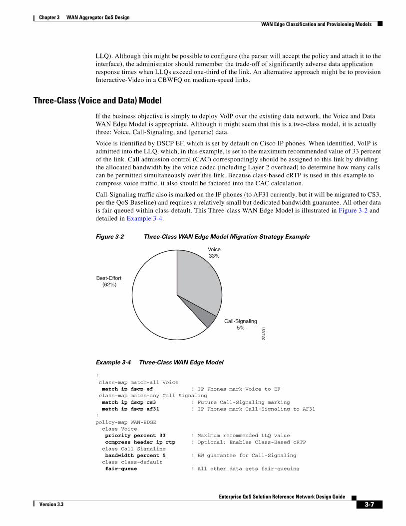
If the business objective is simply to deploy VoIP over the existing data network, the Voice and Data WAN Edge Model is appropriate. Although it might seem that this is a two-class model, it is actually three: Voice, Call-Signaling, and (generic) data.
Voice is identified by DSCP EF, which is set by default on Cisco IP phones. When identified, VoIP is admitted into the LLQ, which, in this example, is set to the maximum recommended value of 33 percent of the link. Call admission control (CAC) correspondingly should be assigned to this link by dividing the allocated bandwidth by the voice codec (including Layer 2 overhead) to determine how many calls can be permitted simultaneously over this link. Because class-based cRTP is used in this example to compress voice traffic, it also should be factored into the CAC calculation.
Call-Signaling traffic also is marked on the IP phones (to AF31 currently, but it will be migrated to CS3, per the QoS Baseline) and requires a relatively small but dedicated bandwidth guarantee. All other data is fair-queued within class-default. This Three-class WAN Edge Model is illustrated in Figure 3-2 and detailed in Example 3-4.
Figure 3-2 Three-Class WAN Edge Model Migration Strategy Example
Voice33%
Call-Signaling5%
Best-Effort (62%)
2248
31
Example 3-4 Three-Class WAN Edge Model
! class-map match-all Voice match ip dscp ef ! IP Phones mark Voice to EF class-map match-any Call Signaling match ip dscp cs3 ! Future Call-Signaling marking match ip dscp af31 ! IP Phones mark Call-Signaling to AF31 !policy-map WAN-EDGE class Voice priority percent 33 ! Maximum recommended LLQ value compress header ip rtp ! Optional: Enables Class-Based cRTP class Call Signaling bandwidth percent 5 ! BW guarantee for Call-Signaling class class-default fair-queue ! All other data gets fair-queuing
3-7Enterprise QoS Solution Reference Network Design Guide
Version 3.3
Chapter 3 WAN Aggregator QoS Design WAN Edge Classification and Provisioning Models
!
Sometimes administrators explicitly create a class map that functions as the MQC class-default. For instance, an administrator might create a class along the lines of that shown in the following code:
class-map match-all BEST-EFFORT match any
or even:
class-map match-all BEST-EFFORT match access-group 101...access-list 101 permit ip any any
These additional configurations are superfluous and inefficient for the router to process. The MQC implicit class-default should be used instead.
Another advantage of using the MQC implicit class-default is that (currently, before Consistent QoS Behavior code) on nondistributed platforms, class-default is the only class that supports fair queuing within it.
Verification command:
• show policy
Verification Command: show policy
The preceding three-class policy, like any other MQC policy, can be verified using the show policy command, as shown in Example 3-5.
Example 3-5 Verification of Three-Class WAN Edge Policy
RBR-2691-Right#show policy WAN-EDGE Policy Map WAN-EDGE Class VOICE Strict Priority ! Voice will get LLQ Bandwidth 33 (%) ! LLQ is provisioned to 33% compress: header ip rtp ! cRTP is enabled Class CALL-SIGNALING Bandwidth 5 (%) Max Threshold 64 (packets) ! Call-Signaling gets 5% BW Class class-default Flow based Fair Queueing ! Data will get FQ Bandwidth 0 (kbps) Max Threshold 64 (packets)RBR-2691-Right#
The Five-Class WAN Edge Model builds on the previous Three-Class WAN Edge Model and includes a provision for a Critical Data class and a Scavenger class.
The new Critical Data class requires Transactional Data traffic to be marked to DSCP AF21 (or AF22, in the case of dual-rate policers deployed within the campus). Additionally, IGP routing (marked by the routers as CS6) and Network-Management traffic (recommended to be marked to CS2) are protected within this class. In this example, the Critical Data class is provisioned to 36 percent of the link and DSCP-based WRED is enabled on it.
The Scavenger class constrains any traffic marked to DSCP CS1 to 1 percent of the link; this allows class-default to use the remaining 25 percent. However, to constrain Scavenger to 1 percent, an explicit bandwidth guarantee (of 25 percent) must be given to the Best-Effort class. Otherwise, if class-default is not explicitly assigned a minimum bandwidth guarantee, the Scavenger class still can rob it of
3-8Enterprise QoS Solution Reference Network Design Guide
Version 3.3

Chapter 3 WAN Aggregator QoS DesignWAN Edge Classification and Provisioning Models
bandwidth. This is because of the way the CBWFQ algorithm has been coded: If classes protected with a bandwidth statement are offered more traffic than their minimum bandwidth guarantee, the algorithm tries to protect such excess traffic at the direct expense of robbing bandwidth from class-default (if class-default is configured with fair-queue), unless class-default itself has a bandwidth statement (providing itself with a minimum bandwidth guarantee). However, assigning a bandwidth statement to class-default (on nondistributed platforms) currently precludes the enabling of fair queuing (fair-queue) on this class and forces FIFO queuing on class-default (this limitation is to be removed with the release of Consistent QoS Behavior code).
An additional implication of using a bandwidth statement on class-default is that even though 25 percent of the link is reserved explicitly for class-default, the parser will not attach the policy to an interface unless the max-reserved-bandwidth 100 command is entered on the interface before the service-policy output statement. This is because the parser adds the sum of the bandwidth statements (regardless of whether one of these is applied to the class-default) and, if the total is in excess of 75 percent of the link’s bandwidth, rejects the application of the policy to the interface. This is shown in the following code:
!interface Multilink1 description T1 to Branch#60 ip address 10.1.112.1 255.255.255.252 max-reserved-bandwidth 100 ! overrides the default 75% BW limit service-policy output WAN-EDGE ! attaches the MQC policy ppp multilink ppp multilink group 1!
Furthermore, WRED can be enabled on the Best-Effort class to provide congestion management. Because all traffic assigned to the default class is to be marked to the same DSCP value (of 0), it would be superfluous to enable DSCP-based WRED on such a class; WRED (technically, RED, in this case because all the [IP Precedence] weights are the same) would suffice.
This Five-Class WAN Edge Model is illustrated in Figure 3-3 and detailed in Example 3-6.
Figure 3-3 Five-Class WAN Edge Model Bandwidth Allocation Example
Voice33%
Call-Signaling5%
Critical Data 36%
Best-Effort 25%
Scavenger 1%
2248
32
Example 3-6 Five-Class WAN Edge Model
!class-map match-all Voice match ip dscp ef ! IP Phones mark Voice to EFclass-map match-any Call Signaling
3-9Enterprise QoS Solution Reference Network Design Guide
Version 3.3
Chapter 3 WAN Aggregator QoS Design WAN Edge Classification and Provisioning Models
match ip dscp cs3 ! Future Call-Signaling marking bandwidth percent 1 ! Current Call-Signaling markingclass-map match-any Critical Data match ip dscp cs6 ! Routers mark Routing traffic to CS6 match ip dscp af21 af22 ! Recommended markings for Transactional-Data match ip dscp cs2 ! Recommended marking for Network Managementclass-map match-all Scavenger match ip dscp cs1 ! Scavenger marking! policy-map WAN-EDGE class Voice priority percent 33 ! Voice gets 33% of LLQ class Call Signaling bandwidth percent 5 ! BW guarantee for Call-Signaling class Critical Data bandwidth percent 36 ! Critical Data class gets 36% BW guarantee random-detect dscp-based ! Enables DSCP-WRED for Critical-Data class class Scavenger bandwidth percent 1 ! Scavenger class is throttled class class-default bandwidth percent 25 ! Default class gets a 25% BW guarantee random-detect ! Enables WRED for class-default!
Verification command:
• show policy
High Link Speed QoS Class ModelsHigh-speed links (such as multiple T1/E1 or above speeds) allow for the provisioning of Voice, Interactive-Video, and multiple classes of data, according to the design rules presented in this chapter (for example, 25 percent for Best Effort class and < 33 percent for all LLQs).
Enabling QoS only optimizes the efficiency of bandwidth utilization; it does not create bandwidth. Therefore, it is important to have adequate bandwidth for all the applications being provisioned. Furthermore, as WAN bandwidth is becoming less expensive, higher-speed links are becoming more popular.
Even if adequate bandwidth exists for up to 11 classes of traffic, as outlined by the QoS Baseline Model, not all enterprises are comfortable with deploying such complex QoS policies at this time. Therefore, it is recommended to start simple, but with room to grow into more complex models. Figure 13-4 illustrates a simple migration strategy showing which classes are good candidates for subdivision into more granular classes as future needs arise.
3-10Enterprise QoS Solution Reference Network Design Guide
Version 3.3
Chapter 3 WAN Aggregator QoS DesignWAN Edge Classification and Provisioning Models
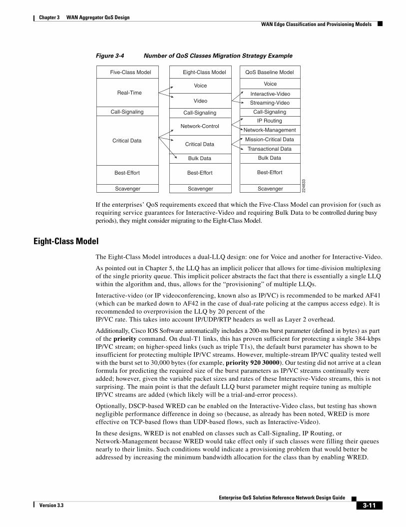
Figure 3-4 Number of QoS Classes Migration Strategy Example
Five-Class Model
Scavenger
Critical Data
Call-Signaling
Best-Effort
Real-Time
Eight-Class Model
Critical Data
Video
Call-Signaling
Best-Effort
Voice
Bulk Data
Network-Control
Scavenger
QoS Baseline Model
Network-Management
Call-Signaling
Streaming-Video
Transactional Data
Interactive-Video
Voice
Best-Effort
IP Routing
Mission-Critical Data
Scavenger
Bulk Data
2248
33
If the enterprises’ QoS requirements exceed that which the Five-Class Model can provision for (such as requiring service guarantees for Interactive-Video and requiring Bulk Data to be controlled during busy periods), they might consider migrating to the Eight-Class Model.
Eight-Class Model
The Eight-Class Model introduces a dual-LLQ design: one for Voice and another for Interactive-Video.
As pointed out in Chapter 5, the LLQ has an implicit policer that allows for time-division multiplexing of the single priority queue. This implicit policer abstracts the fact that there is essentially a single LLQ within the algorithm and, thus, allows for the “provisioning” of multiple LLQs.
Interactive-video (or IP videoconferencing, known also as IP/VC) is recommended to be marked AF41 (which can be marked down to AF42 in the case of dual-rate policing at the campus access edge). It is recommended to overprovision the LLQ by 20 percent of the IP/VC rate. This takes into account IP/UDP/RTP headers as well as Layer 2 overhead.
Additionally, Cisco IOS Software automatically includes a 200-ms burst parameter (defined in bytes) as part of the priority command. On dual-T1 links, this has proven sufficient for protecting a single 384-kbps IP/VC stream; on higher-speed links (such as triple T1s), the default burst parameter has shown to be insufficient for protecting multiple IP/VC streams. However, multiple-stream IP/VC quality tested well with the burst set to 30,000 bytes (for example, priority 920 30000). Our testing did not arrive at a clean formula for predicting the required size of the burst parameters as IP/VC streams continually were added; however, given the variable packet sizes and rates of these Interactive-Video streams, this is not surprising. The main point is that the default LLQ burst parameter might require tuning as multiple IP/VC streams are added (which likely will be a trial-and-error process).
Optionally, DSCP-based WRED can be enabled on the Interactive-Video class, but testing has shown negligible performance difference in doing so (because, as already has been noted, WRED is more effective on TCP-based flows than UDP-based flows, such as Interactive-Video).
In these designs, WRED is not enabled on classes such as Call-Signaling, IP Routing, or Network-Management because WRED would take effect only if such classes were filling their queues nearly to their limits. Such conditions would indicate a provisioning problem that would better be addressed by increasing the minimum bandwidth allocation for the class than by enabling WRED.
3-11Enterprise QoS Solution Reference Network Design Guide
Version 3.3

Chapter 3 WAN Aggregator QoS Design WAN Edge Classification and Provisioning Models
Additionally, the Eight-Class Model subdivides the preferential data class to separate control plane traffic (IP routing and Network-Management applications) from business-critical data traffic. Interior Gateway Protocol (such as RIP, EIGRP, OSPF, and IS-IS) packets are protected through the PAK_priority mechanism within the router. However, EGP protocols, such as BGP, do not get PAK_priority treatment and might need explicit bandwidth guarantees to ensure that peering sessions do not reset during periods of congestion. Additionally, administrators might want to protect network-management access to devices during periods of congestion.
The other class added to this model is for bulk traffic (Bulk Data class), which is also spun away from the Critical Data class. Because TCP continually increases its window sizes, which is especially noticeable in long sessions (such as large file transfers), constraining Bulk Data to its own class alleviates other data classes from being dominated by such large file transfers. Bulk Data is identified by DSCP AF11 (or AF12, in the case of dual-rate policing at the campus access edges). DSCP-based WRED can be enabled on the Bulk Data class (and also on the Critical Data class).
Figure 3-5 shows sample bandwidth allocations of an Eight-Class Model (for a dual-T1 link example). Figure 3-5 also shows how this model can be derived from the Five-Class Model in a manner that maintains respective bandwidth allocations as consistently as possible, which increases the overall end-user transparency of such a migration.
Figure 3-5 Eight-Class WAN Edge Model Bandwidth Allocations Example
Voice18%
Best-Effort 25%
Bulk Data 4%
Critical Data 27%
Call-Signaling 5%
Interactive-Video15%
Network-Control 5%
*Dual-T1 Link Example
Scavenger 1%
2248
34
Example 3-7 shows the corresponding configuration (over a dual-T1 link) for the Eight-Class Model.
Example 3-7 Eight-Class WAN Edge Model
!class-map match-all Voice match ip dscp ef ! IP Phones mark Voice to EFclass-map match-all Interactive Video match ip dscp af41 af42 ! Recommended markings for IP/VCclass-map match-any Call Signaling match ip dscp cs3 ! Future Call-Signaling marking match ip dscp af31 ! Current Call-Signaling markingclass-map match-any Network Control
3-12Enterprise QoS Solution Reference Network Design Guide
Version 3.3
Chapter 3 WAN Aggregator QoS DesignWAN Edge Classification and Provisioning Models
match ip dscp cs6 ! Routers mark Routing traffic to CS6 match ip dscp cs2 ! Recommended marking for Network Managementclass-map match-all Critical Data match ip dscp af21 af22 ! Recommended markings for Transactional-Dataclass-map match-all Bulk Data match ip dscp af11 af12 ! Recommended markings for Bulk-Dataclass-map match-all Scavenger match ip dscp cs1 ! Scavenger marking! policy-map WAN-EDGE class Voice priority percent 18 ! Voice gets 552 kbps of LLQ class Interactive Video priority percent 15 ! 384 kbps IP/VC needs 460 kbps of LLQ class Call Signaling bandwidth percent 5 ! BW guarantee for Call-Signaling class Network Control bandwidth percent 5 ! Routing and Network Management get min 5% BW class Critical Data bandwidth percent 27 ! Critical Data gets min 27% BW random-detect dscp-based ! Enables DSCP-WRED for Critical-Data class class Bulk Data bandwidth percent 4 ! Bulk Data gets min 4% BW guarantee random-detect dscp-based ! Enables DSCP-WRED for Bulk-Data class class Scavenger bandwidth percent 1 ! Scavenger class is throttled class class-default bandwidth percent 25 ! Fair-queuing is sacrificed for BW guarantee random-detect ! Enables WRED on class-default!!
Note The Consistent QoS Behavior initiative will enable the configuration of a bandwidth statement along with fair-queue on any class, including class-default, on all platforms.
Verification command:
• show policy
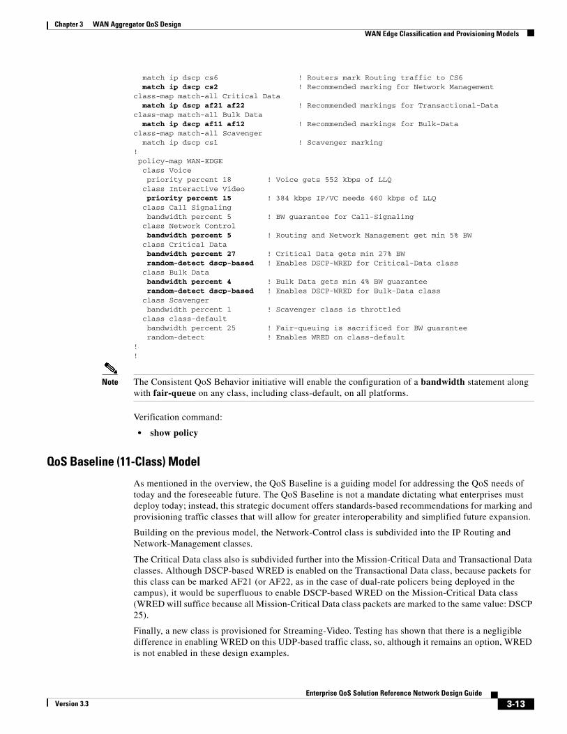
QoS Baseline (11-Class) Model
As mentioned in the overview, the QoS Baseline is a guiding model for addressing the QoS needs of today and the foreseeable future. The QoS Baseline is not a mandate dictating what enterprises must deploy today; instead, this strategic document offers standards-based recommendations for marking and provisioning traffic classes that will allow for greater interoperability and simplified future expansion.
Building on the previous model, the Network-Control class is subdivided into the IP Routing and Network-Management classes.
The Critical Data class also is subdivided further into the Mission-Critical Data and Transactional Data classes. Although DSCP-based WRED is enabled on the Transactional Data class, because packets for this class can be marked AF21 (or AF22, as in the case of dual-rate policers being deployed in the campus), it would be superfluous to enable DSCP-based WRED on the Mission-Critical Data class (WRED will suffice because all Mission-Critical Data class packets are marked to the same value: DSCP 25).
Finally, a new class is provisioned for Streaming-Video. Testing has shown that there is a negligible difference in enabling WRED on this UDP-based traffic class, so, although it remains an option, WRED is not enabled in these design examples.
3-13Enterprise QoS Solution Reference Network Design Guide
Version 3.3
Chapter 3 WAN Aggregator QoS Design WAN Edge Classification and Provisioning Models
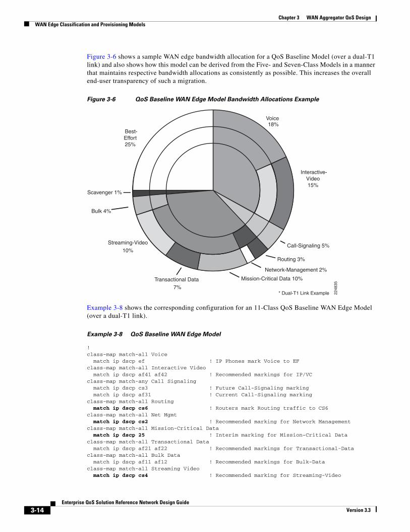
Figure 3-6 shows a sample WAN edge bandwidth allocation for a QoS Baseline Model (over a dual-T1 link) and also shows how this model can be derived from the Five- and Seven-Class Models in a manner that maintains respective bandwidth allocations as consistently as possible. This increases the overall end-user transparency of such a migration.
Figure 3-6 QoS Baseline WAN Edge Model Bandwidth Allocations Example
Voice18%
Best-Effort25%
Bulk 4%
Streaming-Video
10%
Mission-Critical Data 10%
Call-Signaling 5%
Interactive-Video15%
Routing 3%
Network-Management 2%
Transactional Data
7%* Dual-T1 Link Example
Scavenger 1%
2248
35
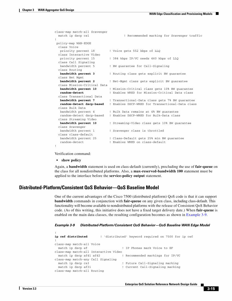
Example 3-8 shows the corresponding configuration for an 11-Class QoS Baseline WAN Edge Model (over a dual-T1 link).
Example 3-8 QoS Baseline WAN Edge Model
!class-map match-all Voice match ip dscp ef ! IP Phones mark Voice to EFclass-map match-all Interactive Video match ip dscp af41 af42 ! Recommended markings for IP/VCclass-map match-any Call Signaling match ip dscp cs3 ! Future Call-Signaling marking match ip dscp af31 ! Current Call-Signaling markingclass-map match-all Routing match ip dscp cs6 ! Routers mark Routing traffic to CS6class-map match-all Net Mgmt match ip dscp cs2 ! Recommended marking for Network Managementclass-map match-all Mission-Critical Data match ip dscp 25 ! Interim marking for Mission-Critical Dataclass-map match-all Transactional Data match ip dscp af21 af22 ! Recommended markings for Transactional-Dataclass-map match-all Bulk Data match ip dscp af11 af12 ! Recommended markings for Bulk-Dataclass-map match-all Streaming Video match ip dscp cs4 ! Recommended marking for Streaming-Video
3-14Enterprise QoS Solution Reference Network Design Guide
Version 3.3
Chapter 3 WAN Aggregator QoS DesignWAN Edge Classification and Provisioning Models
class-map match-all Scavenger match ip dscp cs1 ! Recommended marking for Scavenger traffic! policy-map WAN-EDGE class Voice priority percent 18 ! Voice gets 552 kbps of LLQ class Interactive Video priority percent 15 ! 384 kbps IP/VC needs 460 kbps of LLQ class Call Signaling bandwidth percent 5 ! BW guarantee for Call-Signaling class Routing bandwidth percent 3 ! Routing class gets explicit BW guarantee class Net Mgmt bandwidth percent 2 ! Net-Mgmt class gets explicit BW guarantee class Mission-Critical Data bandwidth percent 10 ! Mission-Critical class gets 10% BW guarantee random-detect ! Enables WRED for Mission-Critical Data class class Transactional Data bandwidth percent 7 ! Transactional-Data class gets 7% BW guarantee random-detect dscp-based ! Enables DSCP-WRED for Transactional-Data class class Bulk Data bandwidth percent 4 ! Bulk Data remains at 4% BW guarantee random-detect dscp-based ! Enables DSCP-WRED for Bulk-Data class class Streaming Video bandwidth percent 10 ! Streaming-Video class gets 10% BW guarantee class Scavenger bandwidth percent 1 ! Scavenger class is throttled class class-default bandwidth percent 25 ! Class-Default gets 25% min BW guarantee random-detect ! Enables WRED on class-default!
Verification command:
• show policy
Again, a bandwidth statement is used on class-default (currently), precluding the use of fair-queue on the class for all nondistributed platforms. Also, a max-reserved-bandwidth 100 statement must be applied to the interface before the service-policy output statement.
Distributed-Platform/Consistent QoS Behavior—QoS Baseline Model
One of the current advantages of the Cisco 7500 (distributed platform) QoS code is that it can support bandwidth commands in conjunction with fair-queue on any given class, including class-default. This functionality will become available to nondistributed platforms with the release of Consistent QoS Behavior code. (As of this writing, this initiative does not have a fixed target delivery date.) When fair-queue is enabled on the main data classes, the resulting configuration becomes as shown in Example 3-9.
Example 3-9 Distributed-Platform/Consistent QoS Behavior—QoS Baseline WAN Edge Model
!ip cef distributed ! 'distributed' keyword required on 7500 for ip cef!class-map match-all Voice match ip dscp ef ! IP Phones mark Voice to EFclass-map match-all Interactive Video match ip dscp af41 af42 ! Recommended markings for IP/VCclass-map match-any Call Signaling match ip dscp cs3 ! Future Call-Signaling marking match ip dscp af31 ! Current Call-Signaling markingclass-map match-all Routing
3-15Enterprise QoS Solution Reference Network Design Guide
Version 3.3

Chapter 3 WAN Aggregator QoS Design WAN Edge Link-Specific QoS Design
match ip dscp cs6 ! Routers mark Routing traffic to CS6class-map match-all Net Mgmt match ip dscp cs2 ! Recommended marking for Network Managementclass-map match-all Mission-Critical Data match ip dscp 25 ! Interim marking for Mission-Critical Dataclass-map match-all Transactional Data match ip dscp af21 af22 ! Recommended markings for Transactional-Dataclass-map match-all Bulk Data match ip dscp af11 af12 ! Recommended markings for Bulk-Dataclass-map match-all Streaming Video match ip dscp cs4 ! Recommended marking for Streaming-Videoclass-map match-all Scavenger match ip dscp cs1 ! Recommended marking for Scavenger traffic!policy-map WAN-EDGE class Voice priority percent 18 ! Voice gets 552 kbps of LLQ class Interactive Video priority percent 15 ! 384 kbps IP/VC needs 460 kbps of LLQ class Call Signaling bandwidth percent 5 ! Bandwidth guarantee for Call-Signaling class Routing bandwidth percent 3 ! Bandwidth guarantee for Routing class Net Mgmt bandwidth percent 2 ! Bandwidth guarantee for Network Management class Mission-Critical Data bandwidth percent 10 ! Mission-Critical data gets min 10% BW guarantee fair-queue ! Applies FQ to Mission-Critical Data class random-detect ! Enables WRED on Mission-Critical Data class class Transactional Data bandwidth percent 7 ! Transactional Data gets min 7% BW guarantee fair-queue ! Applies FQ to Transactional Data class random-detect dscp-based ! Enables DSCP-WRED on Transactional Data class class Bulk Data bandwidth percent 4 ! Bulk Data gets min 4% BW guarantee fair-queue ! Applies FQ to Bulk Data class random-detect dscp-based ! Enables DSCP-WRED on Bulk Data class class Streaming Video bandwidth percent 10 ! Streaming-Video gets min 10% BW guarantee class Scavenger bandwidth percent 1 ! Scavenger class is throttled class class-default bandwidth percent 25 ! Class-Default gets min 25% BW guarantee fair-queue ! Applies FQ to Class-Default random-detect ! Enables WRED on Class-Default!
WAN Edge Link-Specific QoS DesignThe most popular WAN media in use today are leased lines, Frame Relay, and ATM (including ATM-to-Frame Relay Service Interworking). Each of these media can be deployed in three broad categories of link speeds: slow speed (≤ 768 kbps), medium speed (≤ T1/E1), and high speed (multiple T1/E1 or greater). The following sections detail specific designs for each medium at each speed category. Additionally, ISDN QoS design is discussed in the context of a backup WAN link.
3-16Enterprise QoS Solution Reference Network Design Guide
Version 3.3

Chapter 3 WAN Aggregator QoS DesignWAN Edge Link-Specific QoS Design
Leased LinesLeased lines, or point-to-point links, can be configured with HDLC, PPP, or MLP encapsulation. MLP offers the network administrator the most flexibility and deployment options. For example, MLP is the only leased-line protocol that supports LFI on slow-speed links (through MLP LFI). Additionally, as bandwidth requirements grow over time, MLP requires the fewest modifications to accommodate the addition of multiple T1/E1 lines to a WAN link bundle. Furthermore, MLP supports all of the security options of PPP (such as CHAP authentication).
Slow-Speed (≤768 kbps) Leased Lines
Recommendation: Use MLP LFI and cRTP.
For slow-speed leased lines (as illustrated in Figure 3-7), LFI is required to minimize serialization delay. MLP, therefore, is the only encapsulation option on slow-speed leased lines because MLP LFI is the only mechanism available for fragmentation and interleaving on such links. Optionally, cRTP can be enabled either as part of the MQC policy map (as shown in Example 3-10) or under the multilink interface (using the ip rtp header-compression command). Ensure that MLP LFI and cRTP, if enabled, are configured on both ends of the point-to-point link, as shown in Example 3-14.
Figure 3-7 Slow-Speed Leased Lines
Branch RouterWAN Aggregator
MLP Link 768 kbps
2248
36
Example 3-10 Slow-Speed (≤768 kbps) Leased-Line QoS Design Example
!policy-map WAN-EDGE class Voice priority percent 33 ! Maximum recommended LLQ value compress header ip rtp ! Enables Class-Based cRTP class Call Signaling bandwidth percent 5 ! BW guarantee for Call-Signaling… ! A 3 to 5 Class Model can be used!interface Multilink1 description 768 kbps Leased-Line to RBR-3745-Left ip address 10.1.112.1 255.255.255.252 service-policy output WAN-EDGE ! Attaches the MQC policy to Mu1 ppp multilink ppp multilink fragment delay 10 ! Limits serialization delay to 10 ms ppp multilink interleave ! Enables interleaving of Voice with Data ppp multilink group 1!…!interface Serial1/0 bandwidth 786 no ip address encapsulation ppp ppp multilink
3-17Enterprise QoS Solution Reference Network Design Guide
Version 3.3
Chapter 3 WAN Aggregator QoS Design WAN Edge Link-Specific QoS Design
ppp multilink group 1 ! Includes interface Ser1/0 into Mu1 group!
Verification commands:
• show policy
• show interface
• show policy interface
• show ppp multilink
Verification Command: show interface
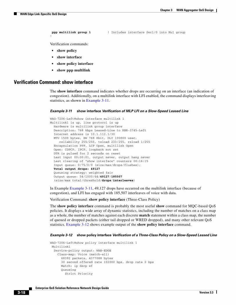
The show interface command indicates whether drops are occurring on an interface (an indication of congestion). Additionally, on a multilink interface with LFI enabled, the command displays interleaving statistics, as shown in Example 3-11.
Example 3-11 show interface Verification of MLP LFI on a Slow-Speed Leased Line
WAG-7206-Left#show interface multilink 1Multilink1 is up, line protocol is up Hardware is multilink group interface Description: 768 kbps Leased-Line to RBR-3745-Left Internet address is 10.1.112.1/30 MTU 1500 bytes, BW 768 Kbit, DLY 100000 usec, reliability 255/255, txload 233/255, rxload 1/255 Encapsulation PPP, LCP Open, multilink Open Open: CDPCP, IPCP, loopback not set DTR is pulsed for 2 seconds on reset Last input 00:00:01, output never, output hang never Last clearing of "show interface" counters 00:16:15 Input queue: 0/75/0/0 (size/max/drops/flushes); Total output drops: 49127 Queueing strategy: weighted fair Output queue: 54/1000/64/49127/185507 (size/max total/threshold/drops/interleaves)
In Example Example 3-11, 49,127 drops have occurred on the multilink interface (because of congestion), and LFI has engaged with 185,507 interleaves of voice with data.
Verification Command: show policy interface (Three-Class Policy)
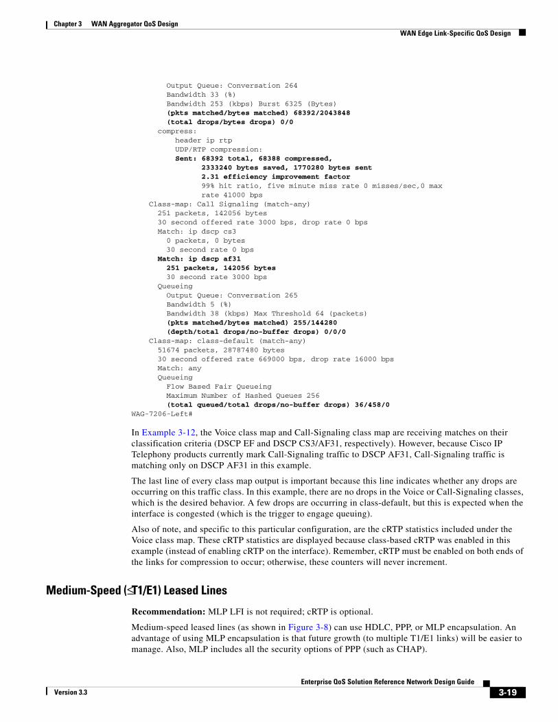
The show policy interface command is probably the most useful show command for MQC-based QoS policies. It displays a wide array of dynamic statistics, including the number of matches on a class map as a whole, the number of matches against each discrete match statement within a class map, the number of queued or dropped packets (either tail dropped or WRED dropped), and many other relevant QoS statistics. Example 3-12 shows example output of the show policy interface command.
Example 3-12 show policy interface Verification of a Three-Class Policy on a Slow-Speed Leased Line
WAG-7206-Left#show policy interface multilink 1 Multilink1 Service-policy output: WAN-EDGE Class-map: Voice (match-all) 68392 packets, 4377088 bytes 30 second offered rate 102000 bps, drop rate 0 bps Match: ip dscp ef Queueing Strict Priority
3-18Enterprise QoS Solution Reference Network Design Guide
Version 3.3
Chapter 3 WAN Aggregator QoS DesignWAN Edge Link-Specific QoS Design
Output Queue: Conversation 264 Bandwidth 33 (%) Bandwidth 253 (kbps) Burst 6325 (Bytes) (pkts matched/bytes matched) 68392/2043848 (total drops/bytes drops) 0/0 compress: header ip rtp UDP/RTP compression: Sent: 68392 total, 68388 compressed, 2333240 bytes saved, 1770280 bytes sent 2.31 efficiency improvement factor 99% hit ratio, five minute miss rate 0 misses/sec,0 max rate 41000 bps Class-map: Call Signaling (match-any) 251 packets, 142056 bytes 30 second offered rate 3000 bps, drop rate 0 bps Match: ip dscp cs3 0 packets, 0 bytes 30 second rate 0 bps Match: ip dscp af31 251 packets, 142056 bytes 30 second rate 3000 bps Queueing Output Queue: Conversation 265 Bandwidth 5 (%) Bandwidth 38 (kbps) Max Threshold 64 (packets) (pkts matched/bytes matched) 255/144280 (depth/total drops/no-buffer drops) 0/0/0 Class-map: class-default (match-any) 51674 packets, 28787480 bytes 30 second offered rate 669000 bps, drop rate 16000 bps Match: any Queueing Flow Based Fair Queueing Maximum Number of Hashed Queues 256 (total queued/total drops/no-buffer drops) 36/458/0WAG-7206-Left#
In Example 3-12, the Voice class map and Call-Signaling class map are receiving matches on their classification criteria (DSCP EF and DSCP CS3/AF31, respectively). However, because Cisco IP Telephony products currently mark Call-Signaling traffic to DSCP AF31, Call-Signaling traffic is matching only on DSCP AF31 in this example.
The last line of every class map output is important because this line indicates whether any drops are occurring on this traffic class. In this example, there are no drops in the Voice or Call-Signaling classes, which is the desired behavior. A few drops are occurring in class-default, but this is expected when the interface is congested (which is the trigger to engage queuing).
Also of note, and specific to this particular configuration, are the cRTP statistics included under the Voice class map. These cRTP statistics are displayed because class-based cRTP was enabled in this example (instead of enabling cRTP on the interface). Remember, cRTP must be enabled on both ends of the links for compression to occur; otherwise, these counters will never increment.
Medium-Speed (≤ T1/E1) Leased Lines
Recommendation: MLP LFI is not required; cRTP is optional.
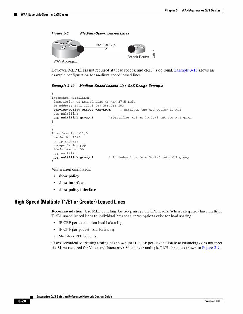
Medium-speed leased lines (as shown in Figure 3-8) can use HDLC, PPP, or MLP encapsulation. An advantage of using MLP encapsulation is that future growth (to multiple T1/E1 links) will be easier to manage. Also, MLP includes all the security options of PPP (such as CHAP).
3-19Enterprise QoS Solution Reference Network Design Guide
Version 3.3
Chapter 3 WAN Aggregator QoS Design WAN Edge Link-Specific QoS Design
Figure 3-8 Medium-Speed Leased Lines
Branch RouterWAN Aggregator
MLP T1/E1 Link
2248
37
However, MLP LFI is not required at these speeds, and cRTP is optional. Example 3-13 shows an example configuration for medium-speed leased lines.
Example 3-13 Medium-Speed Leased-Line QoS Design Example
!interface Multilink1 description T1 Leased-Line to RBR-3745-Left ip address 10.1.112.1 255.255.255.252 service-policy output WAN-EDGE ! Attaches the MQC policy to Mu1 ppp multilink ppp multilink group 1 ! Identifies Mu1 as logical Int for Mu1 group!…!interface Serial1/0 bandwidth 1536 no ip address encapsulation ppp load-interval 30 ppp multilink ppp multilink group 1 ! Includes interface Ser1/0 into Mu1 group!
Verification commands:
• show policy
• show interface
• show policy interface
High-Speed (Multiple T1/E1 or Greater) Leased Lines
Recommendation: Use MLP bundling, but keep an eye on CPU levels. When enterprises have multiple T1/E1-speed leased lines to individual branches, three options exist for load sharing:
• IP CEF per-destination load balancing
• IP CEF per-packet load balancing
• Multilink PPP bundles
Cisco Technical Marketing testing has shown that IP CEF per-destination load balancing does not meet the SLAs required for Voice and Interactive-Video over multiple T1/E1 links, as shown in Figure 3-9.
3-20Enterprise QoS Solution Reference Network Design Guide
Version 3.3

Chapter 3 WAN Aggregator QoS DesignWAN Edge Link-Specific QoS Design
Figure 3-9 High-Speed Leased Lines
Branch RouterWAN Aggregator
MLP LinkMultiple T1/E1
2248
38
On the other hand, IP-CEF per-packet load balancing did meet the required SLAs, but not quite as well as MLP bundling.
MLP bundling attained the best overall SLA values for delay and jitter, but it required more CPU resources than IP CEF per-packet load balancing. If CPU levels are kept under the recommended 75 percent, it is recommended to use MLP bundling for multiple T1/E1 links.
Also, if policy maps that require bandwidth statements on class-default are being attached to the multilink interface, the max-reserved-bandwidth 100 command is required on the interface before the service-policy output statement can be applied, as shown in Example 3-14.
Example 3-14 High-Speed (≥ Multiple T1/E1) Leased Line QoS Design Example
!interface Multilink1 description Dual-T1 to RBR-3745-Left ip address 10.1.112.1 255.255.255.252 max-reserved-bandwidth 100 ! Overrides the default 75% BW limit service-policy output WAN-EDGE ! Attaches the MQC policy to Mu1 ppp multilink ppp multilink group 1 ! Identifies Mu1 as logical int for Mu1 group!…!interface Serial1/0 bandwidth 1536 ! defined on physical interface only no ip address encapsulation ppp ppp multilink ppp multilink group 1 ! includes interface Ser1/0 into Mu1 group!interface Serial1/1 bandwidth 1536 ! defined on physical interface only no ip address encapsulation ppp ppp multilink ppp multilink group 1 ! includes interface Ser1/1 into Mu1 group!
Note Interface bandwidth commands (not to be confused with policy map CBWFQ bandwidth commands) should be defined only on the physical interfaces, not on multilink interfaces. This way, if any physical interfaces go down, the Cisco IOS Software will reflect the change in the multilink interface’s bandwidth for routing and QoS purposes. This change can be verified by the show interface command. However, if a bandwidth statement is configured under the multilink interface, the bandwidth value for the interface will be static even if an underlying physical interface is lost.
Verification commands:
• show policy
3-21Enterprise QoS Solution Reference Network Design Guide
Version 3.3
Chapter 3 WAN Aggregator QoS Design WAN Edge Link-Specific QoS Design
• show interface
• show policy interface
• show ppp multilink
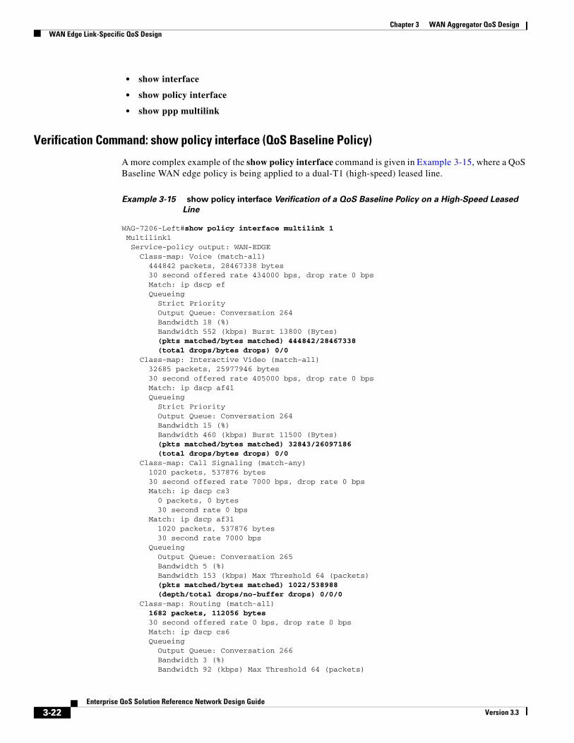
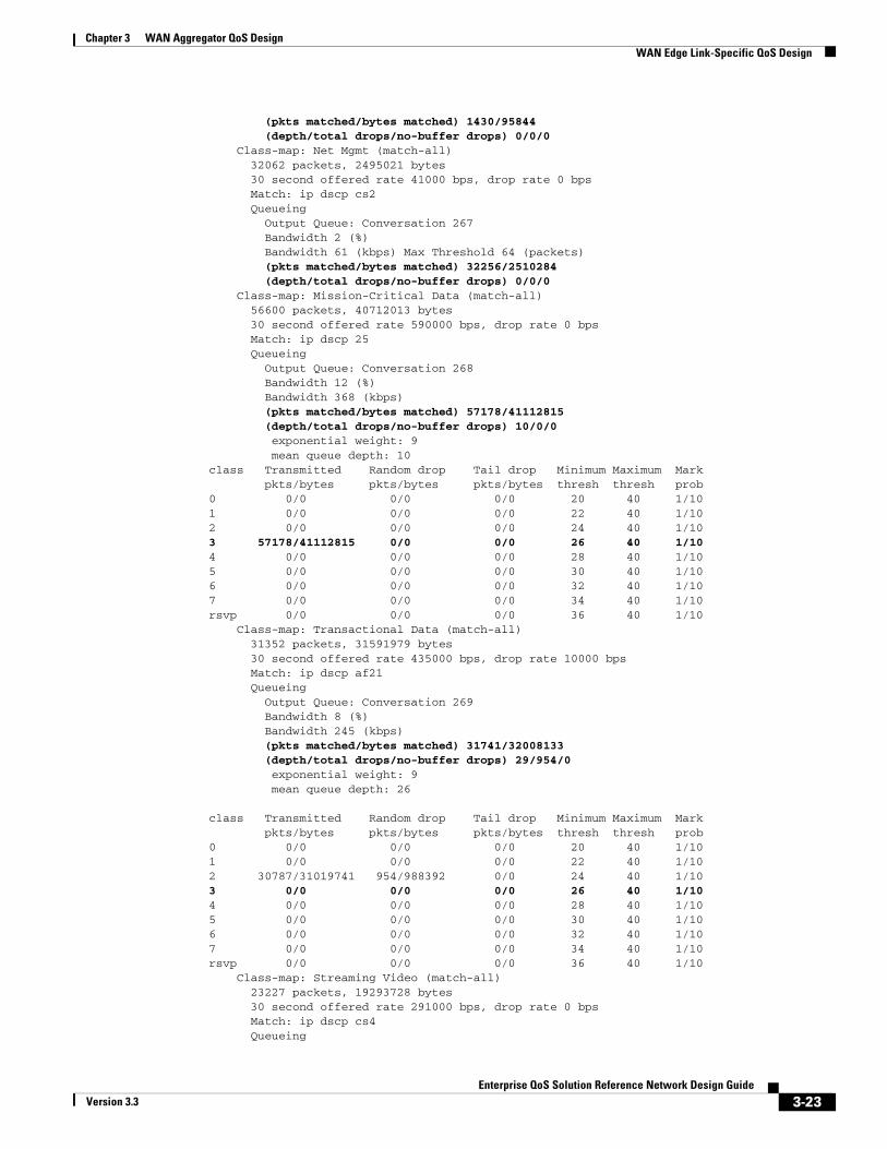
Verification Command: show policy interface (QoS Baseline Policy)
A more complex example of the show policy interface command is given in Example 3-15, where a QoS Baseline WAN edge policy is being applied to a dual-T1 (high-speed) leased line.
Example 3-15 show policy interface Verification of a QoS Baseline Policy on a High-Speed Leased
Line
WAG-7206-Left#show policy interface multilink 1 Multilink1 Service-policy output: WAN-EDGE Class-map: Voice (match-all) 444842 packets, 28467338 bytes 30 second offered rate 434000 bps, drop rate 0 bps Match: ip dscp ef Queueing Strict Priority Output Queue: Conversation 264 Bandwidth 18 (%) Bandwidth 552 (kbps) Burst 13800 (Bytes) (pkts matched/bytes matched) 444842/28467338 (total drops/bytes drops) 0/0 Class-map: Interactive Video (match-all) 32685 packets, 25977946 bytes 30 second offered rate 405000 bps, drop rate 0 bps Match: ip dscp af41 Queueing Strict Priority Output Queue: Conversation 264 Bandwidth 15 (%) Bandwidth 460 (kbps) Burst 11500 (Bytes) (pkts matched/bytes matched) 32843/26097186 (total drops/bytes drops) 0/0 Class-map: Call Signaling (match-any) 1020 packets, 537876 bytes 30 second offered rate 7000 bps, drop rate 0 bps Match: ip dscp cs3 0 packets, 0 bytes 30 second rate 0 bps Match: ip dscp af31 1020 packets, 537876 bytes 30 second rate 7000 bps Queueing Output Queue: Conversation 265 Bandwidth 5 (%) Bandwidth 153 (kbps) Max Threshold 64 (packets) (pkts matched/bytes matched) 1022/538988 (depth/total drops/no-buffer drops) 0/0/0 Class-map: Routing (match-all) 1682 packets, 112056 bytes 30 second offered rate 0 bps, drop rate 0 bps Match: ip dscp cs6 Queueing Output Queue: Conversation 266 Bandwidth 3 (%) Bandwidth 92 (kbps) Max Threshold 64 (packets)
3-22Enterprise QoS Solution Reference Network Design Guide
Version 3.3
Chapter 3 WAN Aggregator QoS DesignWAN Edge Link-Specific QoS Design
(pkts matched/bytes matched) 1430/95844 (depth/total drops/no-buffer drops) 0/0/0 Class-map: Net Mgmt (match-all) 32062 packets, 2495021 bytes 30 second offered rate 41000 bps, drop rate 0 bps Match: ip dscp cs2 Queueing Output Queue: Conversation 267 Bandwidth 2 (%) Bandwidth 61 (kbps) Max Threshold 64 (packets) (pkts matched/bytes matched) 32256/2510284 (depth/total drops/no-buffer drops) 0/0/0 Class-map: Mission-Critical Data (match-all) 56600 packets, 40712013 bytes 30 second offered rate 590000 bps, drop rate 0 bps Match: ip dscp 25 Queueing Output Queue: Conversation 268 Bandwidth 12 (%) Bandwidth 368 (kbps) (pkts matched/bytes matched) 57178/41112815 (depth/total drops/no-buffer drops) 10/0/0 exponential weight: 9 mean queue depth: 10class Transmitted Random drop Tail drop Minimum Maximum Mark pkts/bytes pkts/bytes pkts/bytes thresh thresh prob0 0/0 0/0 0/0 20 40 1/101 0/0 0/0 0/0 22 40 1/102 0/0 0/0 0/0 24 40 1/103 57178/41112815 0/0 0/0 26 40 1/104 0/0 0/0 0/0 28 40 1/105 0/0 0/0 0/0 30 40 1/106 0/0 0/0 0/0 32 40 1/107 0/0 0/0 0/0 34 40 1/10rsvp 0/0 0/0 0/0 36 40 1/10 Class-map: Transactional Data (match-all) 31352 packets, 31591979 bytes 30 second offered rate 435000 bps, drop rate 10000 bps Match: ip dscp af21 Queueing Output Queue: Conversation 269 Bandwidth 8 (%) Bandwidth 245 (kbps) (pkts matched/bytes matched) 31741/32008133 (depth/total drops/no-buffer drops) 29/954/0 exponential weight: 9 mean queue depth: 26
class Transmitted Random drop Tail drop Minimum Maximum Mark pkts/bytes pkts/bytes pkts/bytes thresh thresh prob0 0/0 0/0 0/0 20 40 1/101 0/0 0/0 0/0 22 40 1/102 30787/31019741 954/988392 0/0 24 40 1/103 0/0 0/0 0/0 26 40 1/104 0/0 0/0 0/0 28 40 1/105 0/0 0/0 0/0 30 40 1/106 0/0 0/0 0/0 32 40 1/107 0/0 0/0 0/0 34 40 1/10rsvp 0/0 0/0 0/0 36 40 1/10 Class-map: Streaming Video (match-all) 23227 packets, 19293728 bytes 30 second offered rate 291000 bps, drop rate 0 bps Match: ip dscp cs4 Queueing
3-23Enterprise QoS Solution Reference Network Design Guide
Version 3.3

Chapter 3 WAN Aggregator QoS Design WAN Edge Link-Specific QoS Design
Output Queue: Conversation 271 Bandwidth 10 (%) Bandwidth 307 (kbps) Max Threshold 64 (packets) (pkts matched/bytes matched) 23683/19672892 (depth/total drops/no-buffer drops) 2/0/0 Class-map: Scavenger (match-all) 285075 packets, 129433625 bytes 30 second offered rate 2102000 bps, drop rate 2050000 bps Match: ip dscp cs1 Queueing Output Queue: Conversation 272 Bandwidth 1 (%) Bandwidth 30 (kbps) Max Threshold 64 (packets) (pkts matched/bytes matched) 291885/132532775 (depth/total drops/no-buffer drops) 64/283050/0 Class-map: class-default (match-any) 40323 packets, 35024924 bytes 30 second offered rate 590000 bps, drop rate 0 bps Match: any Queueing Output Queue: Conversation 273 Bandwidth 25 (%) Bandwidth 768 (kbps) (pkts matched/bytes matched) 41229/35918160 (depth/total drops/no-buffer drops) 12/268/0 exponential weight: 9 mean queue depth: 4class Transmitted Random drop Tail drop Minimum Maximum Mark pkts/bytes pkts/bytes pkts/bytes thresh thresh prob0 40961/35700528 268/217632 0/0 20 40 1/101 0/0 0/0 0/0 22 40 1/102 0/0 0/0 0/0 24 40 1/103 0/0 0/0 0/0 26 40 1/104 0/0 0/0 0/0 28 40 1/105 0/0 0/0 0/0 30 40 1/106 0/0 0/0 0/0 32 40 1/107 0/0 0/0 0/0 34 40 1/10rsvp 0/0 0/0 0/0 36 40 1/10
Important items to note for a given class are the pkts matched statistics (which verify that classification has been configured correctly and that the packets have been assigned to the proper queue) and the total drops statistics (which indicate whether adequate bandwidth has been assigned to the class).
Extremely few drops, if any, are desired in the Voice, Interactive-Video, Call-Signaling, and Routing classes.
Note The Routing class is a special case because of the statistics that it displays. On nondistributed platforms, the classification counter (the first line under the class map) shows any IGP traffic matched by the Routing class (identified by DSCP CS6). But remember that IGP protocols queue separately (because these are handled by the PAK_priority mechanism) and, therefore, do not register queuing statistics within the MQC counters for the Routing class. EGP protocols (such as BGP), on the other hand, do register queuing/dropping statistics within such an MQC class. The situation is different on distributed platforms, where all routing packets (IGP or EGP) are matched and queued within a provisioned Routing class (complete with queuing/dropping statistics through the show policy interface verification command).
3-24Enterprise QoS Solution Reference Network Design Guide
Version 3.3
Chapter 3 WAN Aggregator QoS DesignWAN Edge Link-Specific QoS Design
Few drops are expected in the Mission-Critical Data class. WRED (essentially RED because all packets are marked to the same IPP/DSCP value) is enabled to avoid congestion on this class. Some drops are expected for the Transactional Data class, yet, in this particular example, WRED is minimizing tail drops for this class.
It is normal for the Bulk Data class to show drops (both WRED and tail). This is because the Bulk Data class is being constrained from dominating bandwidth by its large and sustained TCP sessions. The Scavenger class should show very aggressive dropping during periods of congestion. Finally, it is normal for drops to appear in the default class.
Verification Command: show ppp multilink
The show ppp multilink command is useful to verify that multiple physical links are correctly associated and included in the MLP bundle, as shown in Example 3-16. Also, the load (which might not quite hit 255/255) indicates congestion on the link.
Example 3-16 show ppp multilink Verification of a High-Speed Leased Line
WAG-7206-Left#show ppp multilinkMultilink1, bundle name is RBR-3745-Left Bundle up for 00:28:33, 254/255 load Receive buffer limit 24384 bytes, frag timeout 1000 ms 0/0 fragments/bytes in reassembly list 0 lost fragments, 2 reordered 0/0 discarded fragments/bytes, 0 lost received 0xE8F received sequence, 0x9A554 sent sequence Member links: 2 active, 0 inactive (max not set, min not set) Se1/0, since 00:28:35, 1920 weight, 1496 frag size Se1/1, since 00:28:33, 1920 weight, 1496 frag size
Frame RelayRecommendation: For the latest feature combinations and management options, use class-based Frame Relay traffic shaping whenever possible.
Frame Relay networks are the most popular WANs in use today because of the low costs associated with them. Frame Relay is a nonbroadcast multiaccess (NBMA) technology that frequently utilizes oversubscription to achieve cost savings (similar to airlines overselling seats on flights to achieve maximum capacity and profitability).
To manage oversubscription and potential speed mismatches between senders and receivers, a traffic-shaping mechanism must be used with Frame Relay. Either Frame Relay traffic shaping (FRTS) or class-based FRTS can be used. The primary advantage of using class-based FRTS is management because shaping statistics and queuing statistics are displayed jointly with the show policy interface verification command and are included in the SNMPv2 Cisco class-based QoS Management Information Base (MIB).
FRTS and class-based FRTS require the following parameters to be defined:
• Committed information rate (CIR)
• Committed burst rate (Bc)
• Excess burst rate (Be)
• Minimum CIR
• Fragment size (required only on slow-speed links)
3-25Enterprise QoS Solution Reference Network Design Guide
Version 3.3
Chapter 3 WAN Aggregator QoS Design WAN Edge Link-Specific QoS Design
Committed Information Rate
Recommendation: Set the CIR to 95 percent of the PVC contracted speed.
In most Frame Relay networks, a central site’s high-speed links connect to lower-speed links to/from many remote offices. For example, consider a central site that sends out data at 1.536 Mbps, while a remote branch might have only a 56-kbps circuit into it. This speed mismatch can cause congestion delays and drops. In addition, there is typically a many-to-one ratio of remote branches to central hubs, making it possible for many remote sites to send traffic at a rate that can overwhelm the T1 at the hub. Both scenarios can cause frame buffering in the provider network, which introduces jitter, delay, and loss.
The only solution to guarantee service-level quality is to use traffic shaping at both the central and remote routers and to define a consistent CIR at both ends of the Frame Relay PVC. Because the FRTS mechanism does not take Frame Relay overhead (headers and cyclic redundancy checks [CRCs]) into account in its calculations, it is recommended that the CIR be set slightly below the contracted speed of the PVC. Cisco Technical Marketing testing has shown that setting the CIR to 95 percent of the contracted speed of the PVC engages the queuing mechanism (LLQ/CBWFQ) slightly early and improves service levels for Real-Time applications, like Voice.
Committed Burst Rate
Recommendation: Set the Bc to CIR/100 on nondistributed platforms and to CIR/125 on distributed platforms.
With Frame Relay networks, you also need to consider the amount of data that a node can transmit at any given time. A 56-kbps PVC can transmit a maximum of 56 kbps of traffic in 1 second. Traffic is not sent during the entire second, however, but only during a defined window called the interval (Tc). The amount of traffic that a node can transmit during this interval is called the committed burst (Bc) rate. By default, Cisco IOS Software sets the Bc to CIR/8. This formula is used for calculating the Tc follows:
Tc = Bc / CIR
For example, a CIR of 56 kbps is given a default Tc of 125 ms (7000 / 56,000). If the 56-kbps CIR is provisioned on a WAN aggregator that has a T1 line-rate clock speed, every time the router sends its allocated 7000 bits, it has to wait 120.5 ms before sending the next batch of traffic. Although this is a good default value for data, it is a bad choice for voice.
By setting the Bc value to a much lower number, you can force the router to send less traffic per interval, but over more frequent intervals per second. This results in significant reduction in shaping delays.
The optimal configured value for Bc is CIR/100, which results in a 10-ms interval (Tc = B / CIR).
On distributed platforms, the Tc must be defined in 4-ms increments. The nearest multiple of 4 ms within the 10-ms target is 8 ms. This interval can be achieved by configuring the Bc to equal CIR/125.
Excess Burst Rate
Recommendation: Set the Be to 0.
If the router does not have enough traffic to send all of its Bc (1000 bits, for example), it can “credit” its account and send more traffic during a later interval. The maximum amount that can be credited to the router’s traffic account is called the excess burst (Be) rate. The problem with Be in converged networks is that this can create a potential for buffering delays within a Frame Relay network (because the receiving side can “pull” the traffic from a circuit only at the rate of Bc, not Bc + Be). To remove this potential for buffering delays, it is recommended to set the Be to 0.
3-26Enterprise QoS Solution Reference Network Design Guide
Version 3.3
Chapter 3 WAN Aggregator QoS DesignWAN Edge Link-Specific QoS Design
Minimum Committed Information Rate
Recommendation: Set the minCIR to CIR. The sum of the minCIR values for all PVCs on the interface must be less than the usable interface bandwidth.
The minimum CIR is the transmit value that a Frame Relay router will “rate down” to when backward-explicit congestion notifications (BECNs) are received. By default, Cisco IOS Software sets the minimum CIR to CIR/2. However, to maintain consistent service levels, it is recommended that adaptive shaping be disabled and that the minimum CIR be set equal to the CIR (which means there is no “rating down”). An exception to this rule would occur if a tool such as Frame Relay voice-adaptive traffic shaping was deployed.
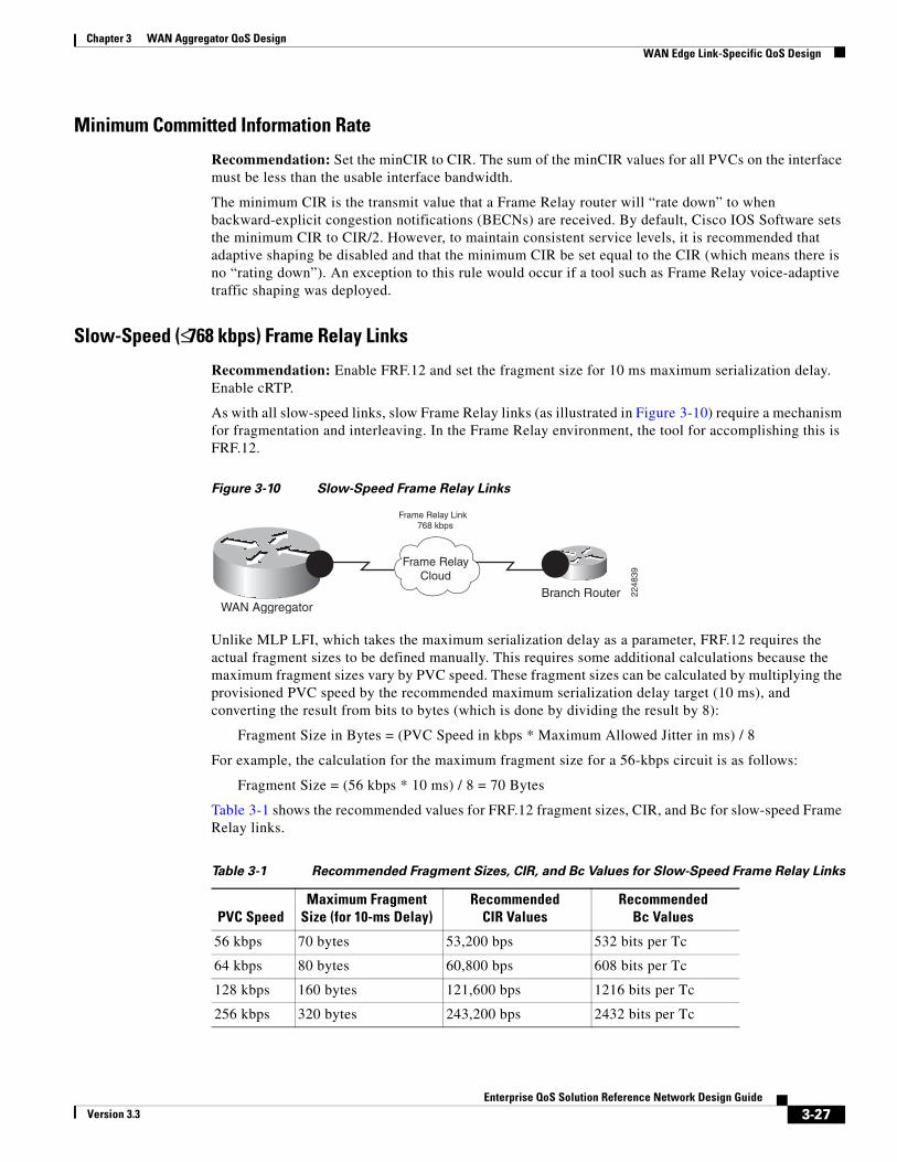
Slow-Speed (≤ 768 kbps) Frame Relay Links
Recommendation: Enable FRF.12 and set the fragment size for 10 ms maximum serialization delay. Enable cRTP.
As with all slow-speed links, slow Frame Relay links (as illustrated in Figure 3-10) require a mechanism for fragmentation and interleaving. In the Frame Relay environment, the tool for accomplishing this is FRF.12.
Figure 3-10 Slow-Speed Frame Relay Links
Branch RouterWAN Aggregator
Frame Relay Link 768 kbps
Frame RelayCloud
2248
39Unlike MLP LFI, which takes the maximum serialization delay as a parameter, FRF.12 requires the actual fragment sizes to be defined manually. This requires some additional calculations because the maximum fragment sizes vary by PVC speed. These fragment sizes can be calculated by multiplying the provisioned PVC speed by the recommended maximum serialization delay target (10 ms), and converting the result from bits to bytes (which is done by dividing the result by 8):
Fragment Size in Bytes = (PVC Speed in kbps * Maximum Allowed Jitter in ms) / 8
For example, the calculation for the maximum fragment size for a 56-kbps circuit is as follows:
Fragment Size = (56 kbps * 10 ms) / 8 = 70 Bytes
Table 3-1 shows the recommended values for FRF.12 fragment sizes, CIR, and Bc for slow-speed Frame Relay links.
Table 3-1 Recommended Fragment Sizes, CIR, and Bc Values for Slow-Speed Frame Relay Links
PVC SpeedMaximum Fragment
Size (for 10-ms Delay)Recommended
CIR ValuesRecommended
Bc Values
56 kbps 70 bytes 53,200 bps 532 bits per Tc
64 kbps 80 bytes 60,800 bps 608 bits per Tc
128 kbps 160 bytes 121,600 bps 1216 bits per Tc
256 kbps 320 bytes 243,200 bps 2432 bits per Tc
3-27Enterprise QoS Solution Reference Network Design Guide
Version 3.3

Chapter 3 WAN Aggregator QoS Design WAN Edge Link-Specific QoS Design
Both FRTS and class-based FRTS require a Frame Relay map class to be applied to the DLCI. Also in both cases, the frame-relay fragment command is applied to the map class. However, unlike FRTS, class-based FRTS does not require frame-relay traffic-shaping to be enabled on the main interface. This is because MQC-based/class-based FRTS requires a hierarchal (or nested) QoS policy to accomplish both shaping and queuing. This hierarchical policy is attached to the Frame Relay map class, which is bound to the DLCI.
As with slow-speed leased-line policies, cRTP can be enabled within the MQC queuing policy under the Voice class. Example 3-17 shows an example of slow-speed Frame Relay link-specific configuration.
Example 3-17 Slow-Speed (≤ 768 kbps) Frame Relay QoS Design Example
!policy-map MQC-FRTS-768 class class-default shape average 729600 7296 0 ! Enables MQC-Based FRTS service-policy WAN-EDGE ! Queues packets headed to the shaper
!…!interface Serial2/0 no ip address encapsulation frame-relay!interface Serial2/0.12 point-to-point ip address 10.1.121.1 255.255.255.252 description 768kbps FR Circuit to RBR-3745-Left frame-relay interface-dlci 102 class FR-MAP-CLASS-768 ! Binds the map-class to the FR DLCI!…!map-class frame-relay FR-MAP-CLASS-768 service-policy output MQC-FRTS-768 ! Attaches nested MQC policies to map-class frame-relay fragment 960 ! Enables FRF.12!
Verification commands:
• show policy map
• show policy-map interface
• show frame-relay fragment
Verification Command: show frame-relay fragment
The show frame-relay fragment command, shown in Example 3-18, provides verification of the fragment size, regardless of whether regular FRF.12 fragmentation or Frame Relay voice-adaptive traffic shaping (and fragmentation) is configured for a DLCI. Additionally, dynamic counters monitor how many frames required fragmentation in either direction.
512 kbps 640 bytes 486,400 bps 4864 bits per Tc
768 kbps 960 bytes 729,600 bps 7296 bits per Tc
Table 3-1 Recommended Fragment Sizes, CIR, and Bc Values for Slow-Speed Frame Relay Links
PVC SpeedMaximum Fragment
Size (for 10-ms Delay)Recommended
CIR ValuesRecommended
Bc Values
3-28Enterprise QoS Solution Reference Network Design Guide
Version 3.3
Chapter 3 WAN Aggregator QoS DesignWAN Edge Link-Specific QoS Design
Example 3-18 show frame-relay fragment Verification of a Slow-Speed Frame Relay Link
WAG-7206-Left#show frame-relay fragment 102interface dlci frag-type frag-size in-frag out-frag dropped-fragSerial2/0.12 102 end-to-end 960 5476 2035 0WAG-7206-Left#
Medium-Speed (≤ T1/E1) Frame Relay Links
Recommendation: FRF.12 is not required. cRTP is optional.
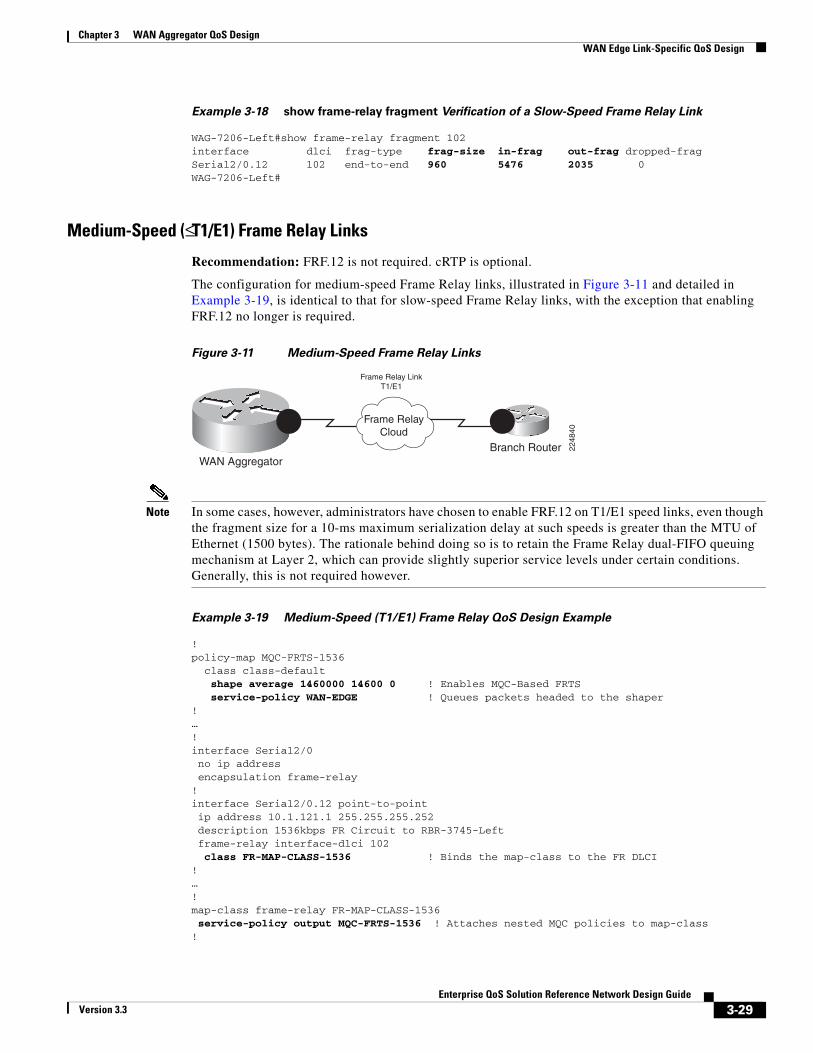
The configuration for medium-speed Frame Relay links, illustrated in Figure 3-11 and detailed in Example 3-19, is identical to that for slow-speed Frame Relay links, with the exception that enabling FRF.12 no longer is required.
Figure 3-11 Medium-Speed Frame Relay Links
Branch RouterWAN Aggregator
Frame Relay LinkT1/E1
Frame RelayCloud
2248
40
Note In some cases, however, administrators have chosen to enable FRF.12 on T1/E1 speed links, even though the fragment size for a 10-ms maximum serialization delay at such speeds is greater than the MTU of Ethernet (1500 bytes). The rationale behind doing so is to retain the Frame Relay dual-FIFO queuing mechanism at Layer 2, which can provide slightly superior service levels under certain conditions. Generally, this is not required however.
Example 3-19 Medium-Speed (T1/E1) Frame Relay QoS Design Example
!policy-map MQC-FRTS-1536 class class-default shape average 1460000 14600 0 ! Enables MQC-Based FRTS service-policy WAN-EDGE ! Queues packets headed to the shaper!…!interface Serial2/0 no ip address encapsulation frame-relay!interface Serial2/0.12 point-to-point ip address 10.1.121.1 255.255.255.252 description 1536kbps FR Circuit to RBR-3745-Left frame-relay interface-dlci 102 class FR-MAP-CLASS-1536 ! Binds the map-class to the FR DLCI!…!map-class frame-relay FR-MAP-CLASS-1536 service-policy output MQC-FRTS-1536 ! Attaches nested MQC policies to map-class!
3-29Enterprise QoS Solution Reference Network Design Guide
Version 3.3
Chapter 3 WAN Aggregator QoS Design WAN Edge Link-Specific QoS Design
Verification commands:
show policy map
show policy-map interface
High-Speed (Multiple T1/E1 and Greater) Frame Relay Links
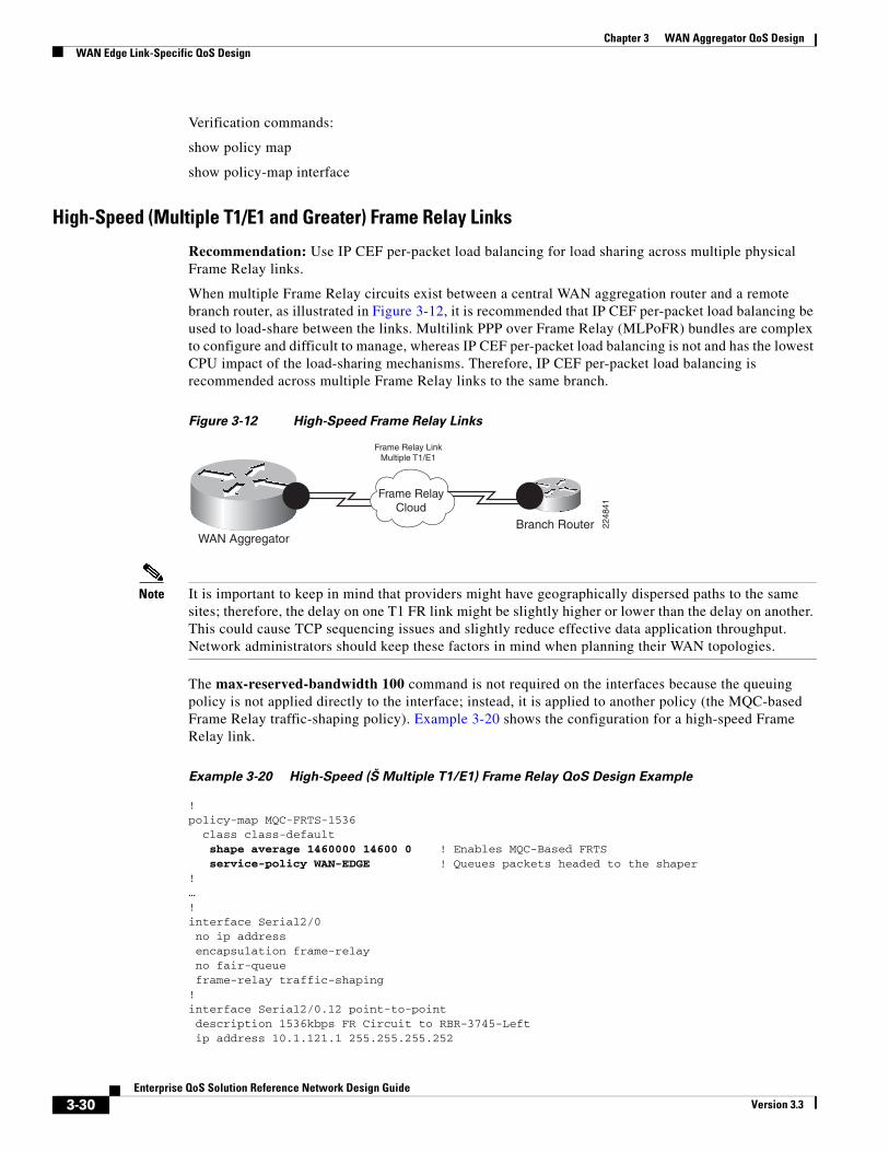
Recommendation: Use IP CEF per-packet load balancing for load sharing across multiple physical Frame Relay links.
When multiple Frame Relay circuits exist between a central WAN aggregation router and a remote branch router, as illustrated in Figure 3-12, it is recommended that IP CEF per-packet load balancing be used to load-share between the links. Multilink PPP over Frame Relay (MLPoFR) bundles are complex to configure and difficult to manage, whereas IP CEF per-packet load balancing is not and has the lowest CPU impact of the load-sharing mechanisms. Therefore, IP CEF per-packet load balancing is recommended across multiple Frame Relay links to the same branch.
Figure 3-12 High-Speed Frame Relay Links
Branch RouterWAN Aggregator
Frame Relay LinkMultiple T1/E1
Frame RelayCloud
2248
41Note It is important to keep in mind that providers might have geographically dispersed paths to the same
sites; therefore, the delay on one T1 FR link might be slightly higher or lower than the delay on another. This could cause TCP sequencing issues and slightly reduce effective data application throughput. Network administrators should keep these factors in mind when planning their WAN topologies.
The max-reserved-bandwidth 100 command is not required on the interfaces because the queuing policy is not applied directly to the interface; instead, it is applied to another policy (the MQC-based Frame Relay traffic-shaping policy). Example 3-20 shows the configuration for a high-speed Frame Relay link.
Example 3-20 High-Speed (Š Multiple T1/E1) Frame Relay QoS Design Example
!policy-map MQC-FRTS-1536 class class-default shape average 1460000 14600 0 ! Enables MQC-Based FRTS service-policy WAN-EDGE ! Queues packets headed to the shaper!…!interface Serial2/0 no ip address encapsulation frame-relay no fair-queue frame-relay traffic-shaping!interface Serial2/0.12 point-to-point description 1536kbps FR Circuit to RBR-3745-Left ip address 10.1.121.1 255.255.255.252
3-30Enterprise QoS Solution Reference Network Design Guide
Version 3.3
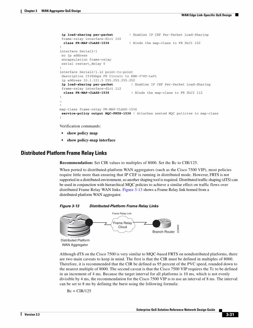
Chapter 3 WAN Aggregator QoS DesignWAN Edge Link-Specific QoS Design
ip load-sharing per-packet ! Enables IP CEF Per-Packet Load-Sharing frame-relay interface-dlci 102 class FR-MAP-CLASS-1536 ! Binds the map-class to FR DLCI 102!interface Serial2/1 no ip address encapsulation frame-relay serial restart_delay 0!interface Serial2/1.12 point-to-point description 1536kbps FR Circuit to RBR-3745-Left ip address 10.1.121.5 255.255.255.252 ip load-sharing per-packet ! Enables IP CEF Per-Packet Load-Sharing frame-relay interface-dlci 112 class FR-MAP-CLASS-1536 ! Binds the map-class to FR DLCI 112!…!map-class frame-relay FR-MAP-CLASS-1536 service-policy output MQC-FRTS-1536 ! Attaches nested MQC policies to map-class!
Verification commands:
• show policy map
• show policy-map interface
Distributed Platform Frame Relay Links
Recommendation: Set CIR values to multiples of 8000. Set the Bc to CIR/125.
When ported to distributed-platform WAN aggregators (such as the Cisco 7500 VIP), most policies require little more than ensuring that IP CEF is running in distributed mode. However, FRTS is not supported in a distributed environment, so another shaping tool is required. Distributed traffic shaping (dTS) can be used in conjunction with hierarchical MQC policies to achieve a similar effect on traffic flows over distributed Frame Relay WAN links. Figure 3-13 shows a Frame Relay link homed from a distributed-platform WAN aggregator.
Figure 3-13 Distributed-Platform Frame Relay Links
Branch Router
WAN Aggregator
Frame Relay Link
Frame RelayCloud
Distributed Platform
2248
42
Although dTS on the Cisco 7500 is very similar to MQC-based FRTS on nondistributed platforms, there are two main caveats to keep in mind. The first is that the CIR must be defined in multiples of 8000. Therefore, it is recommended that the CIR be defined as 95 percent of the PVC speed, rounded down to the nearest multiple of 8000. The second caveat is that the Cisco 7500 VIP requires the Tc to be defined in an increment of 4 ms. Because the target interval for all platforms is 10 ms, which is not evenly divisible by 4 ms, the recommendation for the Cisco 7500 VIP is to use an interval of 8 ms. The interval can be set to 8 ms by defining the burst using the following formula:
Bc = CIR/125
3-31Enterprise QoS Solution Reference Network Design Guide
Version 3.3

Chapter 3 WAN Aggregator QoS Design WAN Edge Link-Specific QoS Design
Table 3-2 gives recommended values for fragment sizes, CIR, and Bc for distributed platforms. (Some values have been slightly rounded for configuration and management simplicity.)
Table 3-2 Recommended Fragment Sizes, CIR, and Bc Values for Distributed Platform Frame
Relay Links
PVC SpeedMaximum Fragment
Size (for 10-ms Delay)Recommended
CIR ValuesRecommended
Bc Values
56 kbps 70 bytes 48,000 bps 384 bits per Tc
64 kbps 80 bytes 56,000 bps 448 bits per Tc
128 kbps 160 bytes 120,000 bps 960 bits per Tc
256 kbps 320 bytes 240,000 bps 1920 bits per Tc
512 kbps 640 bytes 480,000 bps 3840 bits per Tc
768 kbps 960 bytes 720,000 bps 5760 bits per Tc
1536 kbps — 1,440,000 bps 11520 bits per Tc
2048 kbps — 1,920,000 bps 15360 bits per Tc
Example 3-21 Distributed Platform Frame Relay QoS Design (Slow-Speed Link) Example
!!ip cef distributed ! 'distributed' keyword required on 7500 for ip cef!…!policy-map MQC-DTS-768 class class-default shape average 720000 5760 0 ! Enables Distributed Traffic Shaping service-policy WAN-EDGE ! Queues packets headed to the shaper!…!interface Serial1/1/0 no ip address encapsulation frame-relay no fair-queue!interface Serial1/1/0.12 point-to-point description 768kbps FR DLCI to RBR-3745-Left ip address 10.1.121.1 255.255.255.252 frame-relay interface-dlci 102 class FR-MAP-CLASS-768 ! Binds the map-class to the FR-DLCI!…!map-class frame-relay FR-MAP-CLASS-768 service-policy output MQC-DTS-768 ! Attaches nested MQC policies to map-class frame-relay fragment 960 ! Enables FRF.12!
Verification commands:
• show policy map
• show policy-map interface
• show frame-relay fragment (on slow-speed links only)
3-32Enterprise QoS Solution Reference Network Design Guide
Version 3.3

Chapter 3 WAN Aggregator QoS DesignWAN Edge Link-Specific QoS Design
ATMAs with Frame Relay, ATM is an NBMA medium that permits oversubscription and speed mismatches, and thus requires shaping to guarantee service levels. In ATM, however, shaping is included as part of the PVC definition.
Two options exist for carrying voice traffic over slow-speed ATM PVCs: either Multilink PPP over ATM (MLPoATM), in conjunction with MLP LFI, or ATM PVC bundling. ATM PVC bundling is a legacy technique that has drawbacks such as inefficient bandwidth utilization and classification limitations (IP precedence versus DSCP). But sometimes service providers make ATM PVC bundles economically attractive to enterprise customers, so both approaches are discussed.
Slow-Speed (≤ 768 kbps) ATM Links: MLPoATM
Recommendation: Use MLP LFI. Tune the ATM PVC Tx-ring to 3. cRTP can be used only in Cisco IOS Release 12.2(2)T or later.
Serialization delays on slow-speed ATM links, as shown in Figure 3-14, necessitate a fragmentation and interleaving mechanism. The most common ATM adaptation layers (such as AAL5) do not have sequence numbers in the cell headers and, thus, require cells to arrive in the correct order. This requirement makes interleaving a problem that cannot be solved at these ATM adaptation layers and thus must be solved at a higher layer.
Figure 3-14 Slow-Speed MLPoATM Links
Branch RouterWAN Aggregator
MLPoATM Link 768 kbps
ATMCloud
2248
43
A solution to this problem is to run MLPoATM and let MLP LFI handle any necessary fragmentation and interleaving so that such operations are completely transparent to the lower ATM layer. As far as the ATM layer is concerned, all cells arrive in the same order they were sent.
MLPoATM functionality is enabled through the use of virtual-access interfaces. Virtual-access interfaces are built on demand from virtual-template interfaces and inherit their configuration properties from the virtual templates they are built from. Thus, the IP address, service-policy statement, and LFI parameters all are configured on the virtual template, as shown in Example 3-22.
cRTP is supported only on ATM PVCs (through MLPoATM), as of Cisco IOS Release 12.2(2)T.
Additionally, as discussed previously in this chapter, it is recommended that the value of the final output buffer, the Tx-ring, be tuned on slow-speed ATM PVCs to a value of three particles to minimize serialization delay.
Example 3-22 Slow-Speed (≤ 768 kbps) MLPoATM QoS Design Example
!interface ATM4/0 bandwidth 768 no ip address no atm ilmi-keepalive!interface ATM4/0.60 point-to-point
3-33Enterprise QoS Solution Reference Network Design Guide
Version 3.3

Chapter 3 WAN Aggregator QoS Design WAN Edge Link-Specific QoS Design
pvc BRANCH#60 0/60 vbr-nrt 768 768 ! ATM PVC definition tx-ring-limit 3 ! Per-PVC Tx-ring is tuned to 3 particles protocol ppp Virtual-Template60 ! PVC is bound to the Virtual-Template!interface Virtual-Template60 bandwidth 768 ip address 10.200.60.1 255.255.255.252 service-policy output WAN-EDGE ! Attaches MQC policy to Virtual-Template ppp multilink ppp multilink fragment-delay 10 ! Enables MLP Fragmentation ppp multilink interleave ! Enables MLP Interleaving!
Note When using virtual templates for low-speed ATM links, keep the following in mind: -- The dynamic nature of virtual-template interfaces might make network management unwieldy. -- MLPoATM can be supported only on hardware that supports per-VC traffic shaping.
Verification commands:
• show policy map
• show policy-map interface
• show atm pvc
Verification Command: show atm pvc
In ATM, the length of the Tx-ring is defined in particles, not packets. The size of a particle varies according to hardware. For example, on a Cisco 7200 PA-A3, particles are 580 bytes (including a 4-byte ATM core header). This means that a 1500-byte packet would require three particles of buffering. Furthermore, ATM defines Tx-rings on a per-PVC basis, as shown in Example 3-23 and Example 3-24.
Example 3-23 Basic ATM PVC Configuration Example
!interface ATM3/0.1 point-to-point ip address 10.2.12.1 255.255.255.252 pvc 0/12 vbr-nrt 768 768 ! ATM PVC definition !!
The size of a default Tx-ring can be ascertained using the show atm pvc command (an output modifier is used to focus on the relevant portion of the output), as shown in Example 3-24.
Example 3-24 show atm pvc Verification of Tx-ring Setting
WAG-7206-Left#show atm pvc 0/12 | include TxRingLimitVC TxRingLimit: 40 particles
The output shows that the Tx-ring is set, in this instance, to a default value of 40 particles. The Tx-ring for the PVC can be tuned to the recommended setting of 3 using the tx-ring-limit command under the PVC’s definition, as shown in Example 3-25.
3-34Enterprise QoS Solution Reference Network Design Guide
Version 3.3

Chapter 3 WAN Aggregator QoS DesignWAN Edge Link-Specific QoS Design
Example 3-25 Tuning an ATM PVC Tx-ring
WAG-7206-Left(config)#interface atm 3/0.1WAG-7206-Left(config-subif)#pvc 0/12WAG-7206-Le(config-if-atm-vc)#tx-ring-limit 3
The new setting can be verified quickly with the same show atm pvc command variation, as shown in Example 3-25 (see Example 3-26).
Example 3-26 show atm pvc Verification of Tx-ring Setting After Tuning
WAG-7206-Left#show atm pvc 0/12 | include TxRingLimitVC TxRingLimit: 3 particles
Slow-Speed (≤ 768 kbps) ATM Links: ATM PVC Bundles
Recommendation: Queuing policies for voice are not required (because voice uses a dedicated ATM PVC). Tune the ATM PVC Tx-ring to 3.
An alternative option to provisioning QoS on slow-speed ATM PVCs is to use PVC bundles, as illustrated in Figure 3-15. PVC bundles consist of two (or more) PVCs with different ATM traffic contracts, grouped together in a logical association in which IPP levels determine the PVC to which the packet will be directed. The decision to use PVC bundles instead of MLPoATM for slow-speed ATM links is usually a matter of economics (because service providers often offer attractive pricing for PVC bundles) and configuration/management complexity comfort levels.
Figure 3-15 Slow-Speed ATM PVC Bundles
Branch RouterWAN Aggregator
ATM PVC for VoiceATM PVC for Data
ATMCloud
2248
44
In Example 3-27, one PVC (for voice) has a variable bit rate, non-real-time (VBR-nrt) ATM traffic contract and an admission criterion of IPP 5, while another PVC (for data) has an unspecified bit rate (UBR) ATM traffic contract and accepts all other precedence levels.
Again, it is also recommended that the TX-ring be tuned to 3 on such slow-speed ATM PVCs.
Example 3-27 Slow-Speed (ð 768 kbps) ATM PVC Bundles QoS Design Example
!class-map match-any Call Signaling match ip dscp cs3match ip dscp af31class-map match-any Critical Data match ip dscp cs6 match ip dscp af21 match ip dscp cs2!! policy-map WAN-EDGE-DATA-PVC ! Only data queuing is required (no voice) class Call Signaling bandwidth percent 5
3-35Enterprise QoS Solution Reference Network Design Guide
Version 3.3
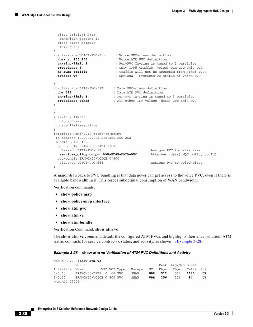
Chapter 3 WAN Aggregator QoS Design WAN Edge Link-Specific QoS Design
class Critical Data bandwidth percent 40 class class-default fair-queue!vc-class atm VOICE-PVC-256 ! Voice PVC-class definition vbr-nrt 256 256 ! Voice ATM PVC definition tx-ring-limit 3 ! Per-PVC Tx-ring is tuned to 3 particles precedence 5 ! Only IPP5 traffic (voice) can use this PVC no bump traffic ! Traffic will not be accepted from other PVCs protect vc ! Optional: Protects VC status of Voice PVC
!vc-class atm DATA-PVC-512 ! Data PVC-class definition ubr 512 ! Data ATM PVC definition tx-ring-limit 3 ! Per-PVC Tx-ring is tuned to 3 particles precedence other ! All other IPP values (data) use this PVC!…!interface ATM3/0 no ip address no atm ilmi-keepalive!interface ATM3/0.60 point-to-point ip address 10.200.60.1 255.255.255.252 bundle BRANCH#60 pvc-bundle BRANCH60-DATA 0/60 class-vc DATA-PVC-512 ! Assigns PVC to data-class service-policy output WAN-EDGE-DATA-PVC ! Attaches (data) MQC policy to PVC pvc-bundle BRANCH60-VOICE 0/600 class-vc VOICE-PVC-256 ! Assigns PVC to voice-class!
A major drawback to PVC bundling is that data never can get access to the voice PVC, even if there is available bandwidth in it. This forces suboptimal consumption of WAN bandwidth.
Verification commands:
• show policy map
• show policy-map interface
• show atm pvc
• show atm vc
• show atm bundle
Verification Command: show atm vc
The show atm vc command details the configured ATM PVCs and highlights their encapsulation, ATM traffic contracts (or service contracts), status, and activity, as shown in Example 3-28.
Example 3-28 show atm vc Verification of ATM PVC Definitions and Activity
WAN-AGG-7200#show atm vc VCD / Peak Avg/Min BurstInterface Name VPI VCI Type Encaps SC Kbps Kbps Cells Sts3/0.60 BRANCH60-DATA 0 60 PVC SNAP UBR 512 512 1145 UP3/0.60 BRANCH60-VOICE 0 600 PVC SNAP VBR 256 256 94 UPWAN-AGG-7200#
3-36Enterprise QoS Solution Reference Network Design Guide
Version 3.3
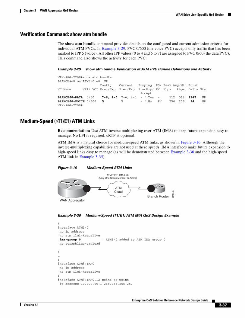
Chapter 3 WAN Aggregator QoS DesignWAN Edge Link-Specific QoS Design
Verification Command: show atm bundle
The show atm bundle command provides details on the configured and current admission criteria for individual ATM PVCs. In Example 3-29, PVC 0/600 (the voice PVC) accepts only traffic that has been marked to IPP 5 (voice). All other IPP values (0 to 4 and 6 to 7) are assigned to PVC 0/60 (the data PVC). This command also shows the activity for each PVC.
Example 3-29 show atm bundle Verification of ATM PVC Bundle Definitions and Activity
WAN-AGG-7200#show atm bundleBRANCH#60 on ATM3/0.60: UP Config Current Bumping PG/ Peak Avg/Min BurstVC Name VPI/ VCI Prec/Exp Prec/Exp PrecExp/ PV Kbps kbps Cells Sts AcceptBRANCH60-DATA 0/60 7-6, 4-0 7-6, 4-0 - / Yes - 512 512 1145 UPBRANCH60-VOICE 0/600 5 5 - / No PV 256 256 94 UPWAN-AGG-7200#
Medium-Speed (≤ T1/E1) ATM Links
Recommendation: Use ATM inverse multiplexing over ATM (IMA) to keep future expansion easy to manage. No LFI is required. cRTP is optional.
ATM IMA is a natural choice for medium-speed ATM links, as shown in Figure 3-16. Although the inverse-multiplexing capabilities are not used at these speeds, IMA interfaces make future expansion to high-speed links easy to manage (as will be demonstrated between Example 3-30 and the high-speed ATM link in Example 3-35).
Figure 3-16 Medium-Speed ATM Links
Branch RouterWAN Aggregator
ATM T1/E1 IMA Link(Only One Group Member Is Active)
ATMCloud
2248
45
Example 3-30 Medium-Speed (T1/E1) ATM IMA QoS Design Example
!interface ATM3/0 no ip address no atm ilmi-keepalive ima-group 0 ! ATM3/0 added to ATM IMA group 0 no scrambling-payload
!…!interface ATM3/IMA0 no ip address no atm ilmi-keepalive!interface ATM3/IMA0.12 point-to-point ip address 10.200.60.1 255.255.255.252
3-37Enterprise QoS Solution Reference Network Design Guide
Version 3.3

Chapter 3 WAN Aggregator QoS Design WAN Edge Link-Specific QoS Design
description T1 ATM-IMA to Branch#60 pvc 0/100 vbr-nrt 1536 1536 ! ATM PVC defined under ATM IMA sub-int max-reserved-bandwidth 100 ! Overrides the default 75% BW limit service-policy output WAN-EDGE ! Attaches MQC policy to PVC !!
Verification commands:
• show policy map
• show policy-map interface
• show atm pvc
• show ima interface atm
High-Speed (Multiple T1/E1) ATM Links
Recommendation: Use ATM IMA and add members to the IMA group, as needed.
Previous options for accommodating multiple T1/E1 links were software-based load-sharing solutions (MLP bundling and IP CEF per-packet load sharing). As such, these methods require additional CPU cycles to accommodate load-sharing multiple physical links. However, with ATM IMA, inverse multiplexing over multiple T1/E1 links, illustrated in Figure 3-17, is done in hardware on the port adaptor/network module. Therefore, ATM IMA scales much more efficiently.
Figure 3-17 High-Speed ATM Links
Branch RouterWAN Aggregator
ATM T1/E1 IMA Link(Multiple Active Group Members)
ATMCloud
2248
46
As mentioned, ATM IMA makes bandwidth expansion easy to manage. For example, all that is required to add another T1 line to the previous example is to add an ima-group statement to the next ATM interface and increase the PVC speed, as shown in Example 3-31.
Example 3-31 High-Speed (Multiple T1/E1 and Greater) ATM IMA QoS Design Example
!interface ATM3/0 no ip address no atm ilmi-keepalive ima-group 0 ! ATM3/0 added to ATM IMA group 0 no scrambling-payload!interface ATM3/1 no ip address no atm ilmi-keepalive ima-group 0 ! ATM3/1 added to ATM IMA group 0 no scrambling-payload!…!interface ATM3/IMA0 no ip address
3-38Enterprise QoS Solution Reference Network Design Guide
Version 3.3
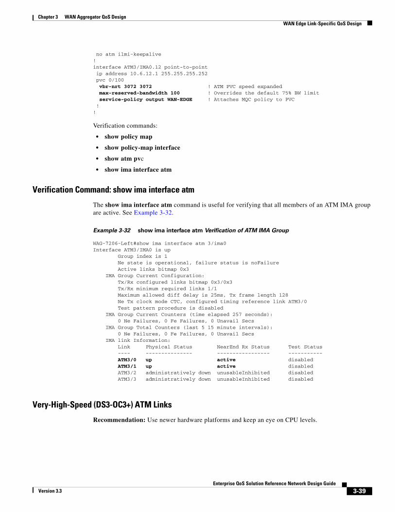
Chapter 3 WAN Aggregator QoS DesignWAN Edge Link-Specific QoS Design
no atm ilmi-keepalive!interface ATM3/IMA0.12 point-to-point ip address 10.6.12.1 255.255.255.252 pvc 0/100 vbr-nrt 3072 3072 ! ATM PVC speed expanded max-reserved-bandwidth 100 ! Overrides the default 75% BW limit service-policy output WAN-EDGE ! Attaches MQC policy to PVC !!
Verification commands:
• show policy map
• show policy-map interface
• show atm pvc
• show ima interface atm
Verification Command: show ima interface atm
The show ima interface atm command is useful for verifying that all members of an ATM IMA group are active. See Example 3-32.
Example 3-32 show ima interface atm Verification of ATM IMA Group
WAG-7206-Left#show ima interface atm 3/ima0Interface ATM3/IMA0 is up Group index is 1 Ne state is operational, failure status is noFailure Active links bitmap 0x3 IMA Group Current Configuration: Tx/Rx configured links bitmap 0x3/0x3 Tx/Rx minimum required links 1/1 Maximum allowed diff delay is 25ms, Tx frame length 128 Ne Tx clock mode CTC, configured timing reference link ATM3/0 Test pattern procedure is disabled IMA Group Current Counters (time elapsed 257 seconds): 0 Ne Failures, 0 Fe Failures, 0 Unavail Secs IMA Group Total Counters (last 5 15 minute intervals): 0 Ne Failures, 0 Fe Failures, 0 Unavail Secs IMA link Information: Link Physical Status NearEnd Rx Status Test Status ---- --------------- ----------------- ----------- ATM3/0 up active disabled ATM3/1 up active disabled ATM3/2 administratively down unusableInhibited disabled ATM3/3 administratively down unusableInhibited disabled
Very-High-Speed (DS3-OC3+) ATM Links
Recommendation: Use newer hardware platforms and keep an eye on CPU levels.
3-39Enterprise QoS Solution Reference Network Design Guide
Version 3.3
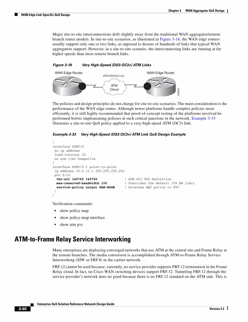
Chapter 3 WAN Aggregator QoS Design WAN Edge Link-Specific QoS Design
Major site-to-site interconnections drift slightly away from the traditional WAN aggregator/remote branch router models. In site-to-site scenarios, as illustrated in Figure 3-18, the WAN edge routers usually support only one or two links, as opposed to dozens or hundreds of links that typical WAN aggregators support. However, in a site-to-site scenario, the interconnecting links are running at far higher speeds than most remote branch links.
Figure 3-18 Very High-Speed (DS3-OC3+) ATM Links
WAN Edge RouterWAN Edge RouterATM DS3/OC3 Link
ATMCloud
2248
47
The policies and design principles do not change for site-to-site scenarios. The main consideration is the performance of the WAN edge router. Although newer platforms handle complex policies more efficiently, it is still highly recommended that proof-of-concept testing of the platforms involved be performed before implementing policies at such critical junctions in the network. Example 3-33 illustrates a site-to-site QoS policy applied to a very-high-speed ATM (OC3) link.
Example 3-33 Very High-Speed (DS3-OC3+) ATM Link QoS Design Example
!interface ATM3/0 no ip address load-interval 30 no atm ilmi-keepalive!interface ATM3/0.1 point-to-point ip address 10.2.12.1 255.255.255.252 pvc 0/12 vbr-nrt 149760 149760 ! ATM OC3 PVC definition max-reserved-bandwidth 100 ! Overrides the default 75% BW limit service-policy output WAN-EDGE ! Attaches MQC policy to PVC !!
Verification commands:
• show policy map
• show policy-map interface
• show atm pvc
ATM-to-Frame Relay Service InterworkingMany enterprises are deploying converged networks that use ATM at the central site and Frame Relay at the remote branches. The media conversion is accomplished through ATM-to-Frame Relay Service Interworking (SIW or FRF.8) in the carrier network.
FRF.12 cannot be used because, currently, no service provider supports FRF.12 termination in the Frame Relay cloud. In fact, no Cisco WAN switching devices support FRF.12. Tunneling FRF.12 through the service provider’s network does no good because there is no FRF.12 standard on the ATM side. This is
3-40Enterprise QoS Solution Reference Network Design Guide
Version 3.3

Chapter 3 WAN Aggregator QoS DesignWAN Edge Link-Specific QoS Design
a problem because fragmentation is a requirement if any of the remote Frame Relay sites uses a circuit speed of 768 kbps or below. However, MLPoATM and MLPoFR provide an end-to-end, Layer 2 fragmentation and interleaving method for low-speed ATM to Frame Relay FRF.8 SIW links.
FRF.8 SIW is a Frame Relay Forum standard for connecting Frame Relay networks with ATM networks. SIW provides a standards-based solution for service providers, enterprises, and end users. In service interworking translation mode, Frame Relay PVCs are mapped to ATM PVCs without the need for symmetric topologies. FRF.8 supports two modes of operation of the interworking function (IWF) for upper-layer user protocol encapsulation:
• Translation mode—Maps between ATM (AAL) and Frame Relay (IETF) encapsulation. It also supports interworking of routed or bridged protocols.
• Transparent mode—Does not map encapsulations, but sends them unaltered. This mode is used when translation is impractical because encapsulation methods do not conform to the supported standards for service interworking.
MLP for LFI on ATM and Frame Relay SIW networks is supported for transparent-mode VCs and translational-mode VCs that support PPP translation (FRF 8.1).
To make MLPoATM and MLPoFR SIW possible, the service provider’s interworking switch must be configured in transparent mode, and the end routers must be capable of recognizing both MLPoATM and MLPoFR headers. This is accomplished with the protocol ppp command for ATM and the frame-relay interface-dlci dlci ppp command for Frame Relay.
When an ATM cell is sent from the ATM side of an ATM-to-Frame Relay SIW connection, the following must happen for interworking to be possible:
1. The sending router encapsulates a packet in the MLPoATM header by the sending router.
2. In transparent mode, the carrier switch prepends a 2-byte Frame Relay DLCI field to the received packet and sends the packet to its Frame Relay interface.
3. The receiving router examines the header of the received packet. If the first 4 bytes after the 2-byte DLCI field of the received packet are 0xfefe03cf, it treats it as a legal MLPoFR packet and sends it to the MLP layer for further processing.
When a frame is sent from the Frame Relay side of an ATM-to-Frame Relay SIW connection, the following must happen for interworking to be possible:
1. The sending router encapsulates a packet in the MLPoFR header.
2. In transparent mode, the carrier switch strips off the 2-byte Frame Relay DLCI field and sends the rest of the packet to its ATM interface.
3. The receiving router examines the header of the received packet. If the first 2 bytes of the received packet are 0x03cf, it treats it as a legal MLPoATM packet and sends it to MLP layer for further processing.
A new ATM-to-Frame Relay SIW standard, FRF.8.1, supports MLPoATM and Frame Relay SIW, but it could be years before all switches are updated to this new standard.
When using MLPoATM and MLPoFR, keep the following in mind: • MLPoATM can be supported only on platforms that support per-VC traffic shaping.
• MLPoATM relies on per-VC queuing to control the flow of packets from the MLP bundle to the ATM PVC.
• MLPoATM requires the MLP bundle to classify the outgoing packets before they are sent to the ATM VC. It also requires the per-VC queuing strategy for the ATM VC to be FIFO because the MLP bundle handles queuing.
• MLPoFR relies on the FRTS engine to control the flow of packets from the MLP bundle to FR VC.
3-41Enterprise QoS Solution Reference Network Design Guide
Version 3.3

Chapter 3 WAN Aggregator QoS Design WAN Edge Link-Specific QoS Design
• cRTP is supported only over ATM links (through MLPoATM), as of Cisco IOS Release 12.2(2)T.
Slow-Speed (≤ 768 kbps) ATM-FR SIW Links
Recommendation: Use MLPoATM and MLPoFR. Use MLP LFI and optimize fragment sizes to minimize cell padding. cRTP can be used only in Cisco IOS Release 12.2(2)T or later. Tune the ATM PVC Tx-ring to 3.
As with any slow-speed WAN media, serialization delay must be addressed with a fragmentation and interleaving mechanism. As previously mentioned, FRF.12 is not an option for SIW links. Therefore, MLP LFI must be used. Generally, MLP LFI requires no additional calculations to configure, but a special case exists when interworking ATM and FR (as illustrated in Figure 3-19) because of the nature of ATM’s fixed cell lengths.
Figure 3-19 Slow-Speed ATM-FR SIW Links
Branch Router
WAN Edge Router
ATM Link 768 kbps
ATM Cloud
Frame RelayCloud
Frame Relay Link 768 kbps
2248
48
When enabling MLPoATM, the fragment size should be optimized so that it fits into an integral number of cells. Otherwise, the bandwidth required could double because of cell padding. For example, if a fragment size of 49 bytes is configured, this fragment would require 2 cells to transmit (because ATM cells have 48-byte payloads). This would generate 57 bytes of overhead (2 cell headers plus 47 bytes of cell padding), which is more than double the fragment itself.
Table 3-3 provides a summary of the optimal fragment-delay parameters for MLPoATM.
Table 3-3 Optimal Fragment-Delay Values for MLP LFI for MLPoATM
PVC SpeedOptimal Fragment
SizeATM Cells
(Rounded Up)ppp multilink
fragment-delay value
56 kbps 84 bytes 2 12 ms
64 kbps 80 bytes 2 10 ms
128 kbps 176 bytes 4 11 ms
256 kbps 320 bytes 7 10 ms
512 kbps 640 bytes 14 10 ms
768 kbps 960 bytes 21 10 ms
A slow-speed ATM-to-Frame Relay SIW configuration is shown next, in two parts:
• The central site WAN aggregator MLPoATM configuration (see Example 3-34)
• The remote branch router MLPoFR configuration (see Example 3-35)
Example 3-34 MLPoATM WAN Aggregator ATM-FR SIW QoS Design Example
!interface ATM4/0 no ip address
3-42Enterprise QoS Solution Reference Network Design Guide
Version 3.3

Chapter 3 WAN Aggregator QoS DesignWAN Edge Link-Specific QoS Design
no atm ilmi-keepalive!interface ATM4/0.60 point-to-point pvc BRANCH#60 0/60 vbr-nrt 256 256 ! ATM PVC definition tx-ring-limit 3 ! Per-PVC Tx-ring is tuned to 3 particles protocol ppp Virtual- Template60 ! Enables MLPoATM!interface Virtual-Template60 bandwidth 256 ip address 10.200.60.1 255.255.255.252 service-policy output WAN-EDGE ! Attaches MQC policy to Virtual-Template ppp multilink ppp multilink fragment-delay 10 ! Enables MLP fragmentation ppp multilink interleave ! Enables MLP interleaving!
Verification commands:
• show policy map
• show policy-map interface
• show atm pvc
• show ppp multilink
Example 3-35 MLPoFR Remote-Branch Router ATM-FR SIW QoS Design Example
!interface Serial6/0 description Parent FR Link for BRANCH#60 no ip address encapsulation frame-relay frame-relay traffic-shaping!interface Serial6/0.60 point-to-point description FR Sub-Interface for BRANCH#60 bandwidth 256 frame-relay interface-dlci 60 ppp Virtual-Template60 ! Enables MLPoFR class FRTS-256kbps ! Binds the map-class to the FR DLCI!interface Virtual-Template60 bandwidth 256 ip address 10.200.60.2 255.255.255.252 service-policy output WAN-EDGE ! Attaches MQC policy to map-class ppp multilink ppp multilink fragment-delay 10 ! Enables MLP fragmentation ppp multilink interleave ! Enables MLP interleaving!…!map-class frame-relay FRTS-256kbps frame-relay cir 243200 ! CIR is set to 95% of FR DLCI rate frame-relay bc 2432 ! Bc is set to CIR/100 frame-relay be 0 ! Be is set to 0 frame-relay mincir 243200 ! MinCIR is set to CIR!
Verification commands:
• show policy map
3-43Enterprise QoS Solution Reference Network Design Guide
Version 3.3
Chapter 3 WAN Aggregator QoS Design WAN Edge Link-Specific QoS Design
• show policy-map interface
• show ppp multilink
ISDNWhen designing VoIP over ISDN networks, special consideration needs to be given to the following issues:
• Link bandwidth varies as B channels are added or dropped.
• RTP packets might arrive out of order when transmitted across multiple B channels.
• CallManager has limitations with locations-based CAC.
Variable Bandwidth
ISDN allows B channels to be added or dropped in response to the demand for bandwidth. The fact that the bandwidth of a link varies over time presents a special challenge to the LLQ/CBWFQ mechanisms of Cisco IOS Software. Before Cisco IOS Release 12.2(2)T, a policy map implementing LLQ could be assigned only a fixed amount of bandwidth. On an ISDN interface, Cisco IOS Software assumes that only 64 kbps is available, even though the interface has the potential to provide 128 kbps, 1.544 Mbps, or 2.408 Mbps of bandwidth. By default, the maximum bandwidth assigned must be less than or equal to 75 percent of the available bandwidth. Hence, before Cisco IOS Release 12.2(2)T, only 75 percent of 64 kbps, or 48 kbps, could be allocated to an LLQ on any ISDN interface. If more was allocated, an error message was generated when the policy map was applied to the ISDN interface. This severely restricted the number of VoIP calls that could be carried.
The solution to this problem was introduced in Cisco IOS Release 12.2(2)T with the priority percent command. This command allows the reservation of a variable bandwidth percentage to be assigned to the LLQ.
MLP Packet Reordering Considerations
MLP LFI is used for fragmentation and interleaving voice and data over ISDN links. LFI segments large data packets into smaller fragments and transmits them in parallel across all the B channels in the bundle. At the same time, voice packets are interleaved between the fragments, thereby reducing their delay. The interleaved packets are not subject to MLP encapsulation; they are encapsulated as regular PPP packets. Hence, they have no MLP sequence numbers and cannot be reordered if they arrive out of sequence.
The packets probably will need to be reordered. The depth of the various link queues in the bundle might differ, causing RTP packets to overtake each other as a result of the difference in queuing delay. The various B channels also might take different paths through the ISDN network and might end up with different transmission delays.
This reordering of packets is not generally a problem for RTP packets. The buffers on the receiving VoIP devices reorder the packets based on the RTP sequence numbers. However, reordering becomes a problem if cRTP is used. The cRTP algorithm assumes that RTP packets are compressed and decompressed in the same order. If they get out of sequence, decompression does not occur correctly.
Multiclass Multilink PPP (MCMP) offers a solution to the reordering problem. With MCMP, the interleaved packets are given a small header with a sequence number, which allows them to be reordered by the far end of the bundle before cRTP decompression takes place. MCMP is supported as of Cisco IOS Release 12.2(13)T.
3-44Enterprise QoS Solution Reference Network Design Guide
Version 3.3
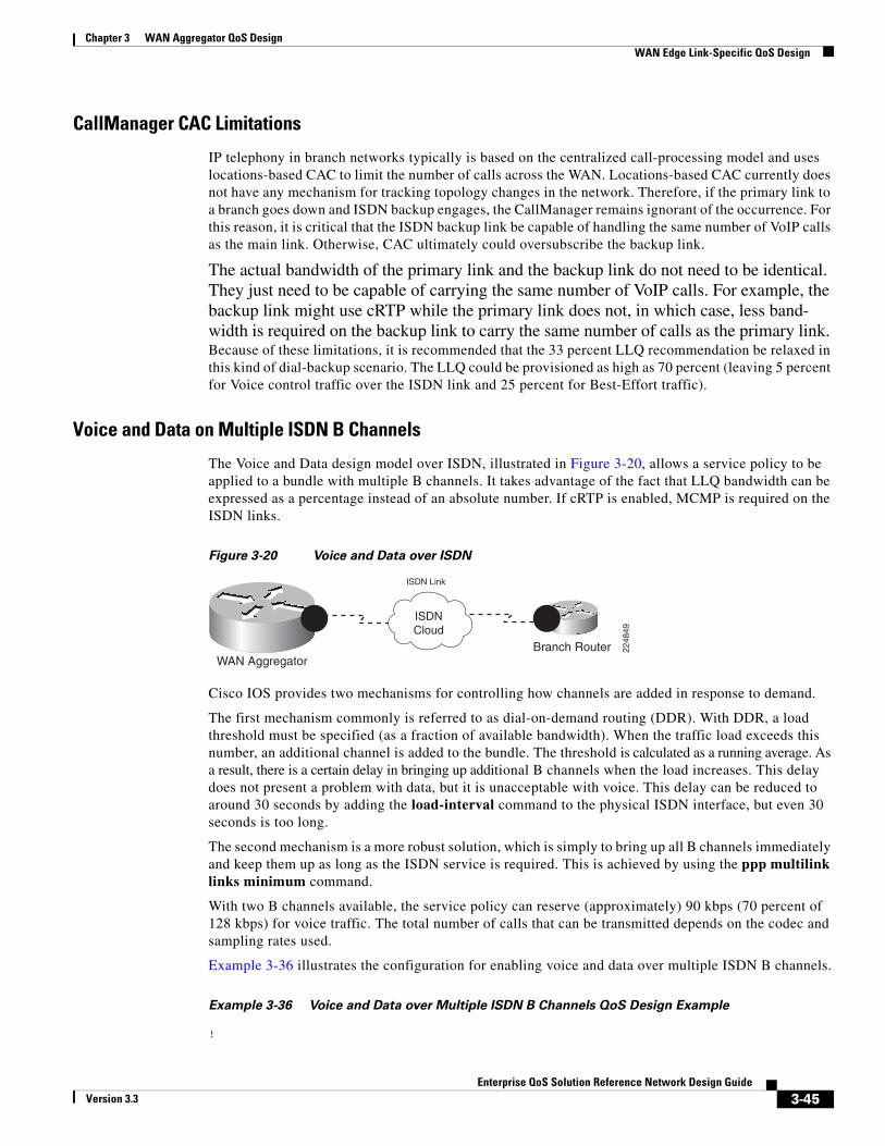
Chapter 3 WAN Aggregator QoS DesignWAN Edge Link-Specific QoS Design
CallManager CAC Limitations
IP telephony in branch networks typically is based on the centralized call-processing model and uses locations-based CAC to limit the number of calls across the WAN. Locations-based CAC currently does not have any mechanism for tracking topology changes in the network. Therefore, if the primary link to a branch goes down and ISDN backup engages, the CallManager remains ignorant of the occurrence. For this reason, it is critical that the ISDN backup link be capable of handling the same number of VoIP calls as the main link. Otherwise, CAC ultimately could oversubscribe the backup link.
The actual bandwidth of the primary link and the backup link do not need to be identical. They just need to be capable of carrying the same number of VoIP calls. For example, the backup link might use cRTP while the primary link does not, in which case, less band-width is required on the backup link to carry the same number of calls as the primary link. Because of these limitations, it is recommended that the 33 percent LLQ recommendation be relaxed in this kind of dial-backup scenario. The LLQ could be provisioned as high as 70 percent (leaving 5 percent for Voice control traffic over the ISDN link and 25 percent for Best-Effort traffic).
Voice and Data on Multiple ISDN B Channels
The Voice and Data design model over ISDN, illustrated in Figure 3-20, allows a service policy to be applied to a bundle with multiple B channels. It takes advantage of the fact that LLQ bandwidth can be expressed as a percentage instead of an absolute number. If cRTP is enabled, MCMP is required on the ISDN links.
Figure 3-20 Voice and Data over ISDN
Branch RouterWAN Aggregator
ISDN Link
ISDNCloud
2248
49
Cisco IOS provides two mechanisms for controlling how channels are added in response to demand.
The first mechanism commonly is referred to as dial-on-demand routing (DDR). With DDR, a load threshold must be specified (as a fraction of available bandwidth). When the traffic load exceeds this number, an additional channel is added to the bundle. The threshold is calculated as a running average. As a result, there is a certain delay in bringing up additional B channels when the load increases. This delay does not present a problem with data, but it is unacceptable with voice. This delay can be reduced to around 30 seconds by adding the load-interval command to the physical ISDN interface, but even 30 seconds is too long.
The second mechanism is a more robust solution, which is simply to bring up all B channels immediately and keep them up as long as the ISDN service is required. This is achieved by using the ppp multilink links minimum command.
With two B channels available, the service policy can reserve (approximately) 90 kbps (70 percent of 128 kbps) for voice traffic. The total number of calls that can be transmitted depends on the codec and sampling rates used.
Example 3-36 illustrates the configuration for enabling voice and data over multiple ISDN B channels.
Example 3-36 Voice and Data over Multiple ISDN B Channels QoS Design Example
!
3-45Enterprise QoS Solution Reference Network Design Guide
Version 3.3

Chapter 3 WAN Aggregator QoS Design Summary
class-map match-all Voice match ip dscp ef!class-map match-any Call Signaling match ip dscp cs3 match ip dscp af31!…!policy-map WAN-EDGE-ISDN class Voice priority percent 70 ! LLQ 33% Rule is relaxed for DDR scenarios compress header ip rtp ! Enables Class-Based cRTP class Call Signaling bandwidth percent 5 ! Bandwidth guarantee for Call-Signaling class class-default fair-queue!interface BRI0/0 encapsulation ppp dialer pool-member 1!interface Dialer1 encapsulation ppp dialer pool 1 dialer remote-name routerB-dialer1 dialer-group 1 dialer string 12345678 service-policy output WAN-EDGE-ISDN ! Attaches MQC policy to Dialer interface ppp multilink ppp multilink fragment-delay 10 ! Enables MLP fragmentation ppp multilink interleave ! Enables MLP interleaving ppp multilink links minimum 2 ! Activates both B Channels immediately ppp multilink multiclass ! Enables MCMP!
Verification commands:
• show policy map
• show policy-map interface
• show ppp multilink
Note For a case study example of WAN Aggregator QoS design, refer to Figure 13-21 and Example 13-37 of the Cisco Press book, End-to-End QoS Network Design by Tim Szigeti and Christina Hattingh.
SummaryThis chapter discussed the QoS requirements of routers performing the role of a WAN aggregator. Specifically, it addressed the need for queuing policies on the WAN edges, combined with shaping policies when NBMA media (such as Frame Relay or ATM) are being used, and link-specific policies, such as LFI/FRF.12 and cRTP, for slow-speed (≤ 768 kbps) links.
For the WAN edges, bandwidth-provisioning guidelines were considered, such as leaving 25 percent of the bandwidth for the Best-Effort class and limiting the sum of all LLQs to 33 percent.
Three categories of WAN link speeds and their design implications were presented:
3-46Enterprise QoS Solution Reference Network Design Guide
Version 3.3
Chapter 3 WAN Aggregator QoS DesignReferences
• Slow-speed (≤ 768 kbps) links, which can support only Three- to Five-Class QoS models and require LFI mechanisms and cRTP.
• Medium-speed (≤ T1/E1) links, which, likewise, can support only Three- to Five-Class QoS Models but no longer require LFI mechanisms. cRTP becomes optional.
• High-speed (multiple T1/E1 or greater) links, which can support 5- to 11-Class QoS Models. No LFI is required on such links. cRTP likely would have a high CPU cost (compared to realized bandwidth savings) and, as such, generally is not recommended for such links. Additionally, some method of load sharing, bundling, or inverse multiplexing is required to distribute the traffic across multiple physical links.
These principles then were applied to certain WAN media designs—specifically, for leased lines, Frame Relay, ATM, and ATM-to-Frame Relay SIW. The corner case of ISDN as a backup WAN link also was considered.
References
Standards • RFC 2474 "Definition of the Differentiated Services Field (DS Field) in the IPv4 and IPv6 Headers
http://www.ietf.org/rfc/rfc2474
• RFC 2597 "Assured Forwarding PHB Group"
http://www.ietf.org/rfc/rfc2597
• RFC 2697 "A Single Rate Three Color Marker"
http://www.ietf.org/rfc/rfc2697
• RFC 2698 "A Two Rate Three Color Marker"
http://www.ietf.org/rfc/rfc2698
• RFC 3168 "The Addition of Explicit Congestion Notification (ECN) to IP"
http://www.ietf.org/rfc/rfc3168
• RFC 3246 "An Expedited Forwarding PHB (Per-Hop Behavior)"
http://www.ietf.org/rfc/rfc3246
Books • Szigeti, Tim and Christina Hattingh. End-to-End QoS Network Design: Quality of Service in LANs,
WANs and VPNs. Indianapolis: Cisco Press, 2004.
Cisco DocumentationLayer 3 queuing:
• Class-based weighted fair queuing (Cisco IOS Release 12.0.5T)
http://www.cisco.com/univercd/cc/td/doc/product/software/ios120/120newft/120t/120t5/cbwfq.htm
3-47Enterprise QoS Solution Reference Network Design Guide
Version 3.3
Chapter 3 WAN Aggregator QoS Design References
• Low-latency queuing (Cisco IOS Release 12.0.7T)
http://www.cisco.com/univercd/cc/td/doc/product/software/ios120/120newft/120t/120t7/pqcbwfq.ht
• Distributed low-latency queuing (Cisco IOS Release 12.1.5T)
http://www.cisco.com/univercd/cc/td/doc/product/software/ios121/121newft/121t/121t5/dtllqvip.htm
• Low-latency queuing with priority percentage support (Cisco IOS Release 12.2.2T)
http://www.cisco.com/univercd/cc/td/doc/product/software/ios122/122newft/122t/122t2/ftllqpct.htm
Congestion avoidance:
• MQC-based WRED (Cisco IOS Release 12.0.5T)
http://www.cisco.com/univercd/cc/td/doc/product/software/ios120/120newft/120t/120t5/cbwfq.htm
• DiffServ-compliant weighted random early detection (Cisco IOS Release 12.1.5T)
http://www.cisco.com/univercd/cc/td/doc/product/software/ios121/121newft/121t/121t5/dtdswred.htm
• Distributed class-based weighted fair queuing and distributed weighted random early detection (Cisco IOS Release 12.1.5T)
http://www.cisco.com/univercd/cc/td/doc/product/software/ios121/121newft/121t/121t5/dtcbwred.htm
Frame Relay traffic shaping:
• Class-based shaping (Cisco IOS Release 12.1.2T)
http://www.cisco.com/univercd/cc/td/doc/product/software/ios121/121newft/121t/121t2/clsbsshp.htm
• MQC-based Frame Relay traffic shaping (Cisco IOS Release 12.2.13T)
http://www.cisco.com/univercd/cc/td/doc/product/software/ios122/122newft/122t/122t13/frqosmqc.htm
• Distributed traffic shaping (Cisco IOS Release 12.1.5T)
http://www.cisco.com/univercd/cc/td/doc/product/software/ios121/121newft/121t/121t5/dtdts.htm
ATM PVC trafficparameters:
• Configuring ATM traffic parameters
http://www.cisco.com/univercd/cc/td/doc/product/software/ios122/122cgcr/fwan_c/wcfatm.htm#1001126
Link fragmentation and interleaving:
• MLP interleaving and queuing for Real-Time traffic (Cisco IOS Release 12.0)
http://www.cisco.com/univercd/cc/td/doc/product/software/ios120/12cgcr/dial_c/dcppp.htm#4550
• FRF.12 (Cisco IOS Release 12.0.4T)
http://www.cisco.com/univercd/cc/td/doc/product/software/ios120/120newft/120t/120t4/120tvofr/index.htm
• Link fragmentation and interleaving for Frame Relay and ATM virtual circuits (Cisco IOS Release 12.1.5T)
3-48Enterprise QoS Solution Reference Network Design Guide
Version 3.3
Chapter 3 WAN Aggregator QoS DesignReferences
http://www.cisco.com/univercd/cc/td/doc/product/software/ios121/121newft/121t/121t5/dtlfifra.htm
• Distributed link fragmentation and interleaving over leased lines (Cisco IOS Release 12.2.8T)
http://www.cisco.com/univercd/cc/td/doc/product/software/ios122/122newft/122t/122t8/ftdlfi2.htm
• Distributed link fragmentation and interleaving for Frame Relay and ATM interfaces (Cisco IOS Release 12.2.4T)
http://www.cisco.com/univercd/cc/td/doc/product/software/ios122/122newft/122t/122t4/ftdlfi.htm
Compressed Real-Time Protocol:
• RTP and TCP header compression (Cisco IOS Release 12.0.7T)
http://www.cisco.com/univercd/cc/td/doc/product/software/ios120/120newft/120t/120t7/rtpfast.htm
• Class-based RTP and TCP header compression (Cisco IOS Release 12.2.13T)
http://www.cisco.com/univercd/cc/td/doc/product/software/ios122/122newft/122t/122t13/fthdrcmp.htm
Tx-ring:
• Tx-ring tuning
http://www.cisco.com/en/US/tech/tk39/tk824/technologies_tech_note09186a00800fbafc.shtml
PAK_priority:
• Understanding how routing updates and Layer 2 control packets are queued on an interface with a QoS service policy
http://www.cisco.com/warp/public/105/rtgupdates.html
ISDN:
• Multiclass Multilink PPP (Cisco IOS Release 12.2.13T)
http://www.cisco.com/univercd/cc/td/doc/product/software/ios122/122newft/122t/122t13/ftmmlppp.htm
Marking:
• Class-based marking (Cisco IOS Release 12.1.5T)
http://www.cisco.com/univercd/cc/td/doc/product/software/ios121/121newft/121t/121t5/cbpmark2.htm
• Enhanced packet marking (Cisco IOS Release 12.2.13T)
http://www.cisco.com/univercd/cc/td/doc/product/software/ios122/122newft/122t/122t13/ftenpkmk.htm
3-49Enterprise QoS Solution Reference Network Design Guide
Version 3.3
Chapter 3 WAN Aggregator QoS Design References
3-50Enterprise QoS Solution Reference Network Design Guide
Version 3.3