Wall slip of molten high density polyethylene. I. Sliding...
27
Wall slip of molten high density polyethylene. I. Sliding plate rheometer studies S. G. Hatzikiriakos and J. M. Dealy Department of Chemical Engineering, McGill University, Montreal, Canada H3A 2A7 (Received 16 October 1990; accepted 22 January 1991) Synopsis Experiments were performed in a sliding plate rheometer with a high density polyethylene to determine the conditions for the onsetof slip and the relation- ship between slip velocity and shear stress. It was found that melt slip occurs at a critical shear stress of approximately 0.09 MPa in both steady and transient shear tests. The effect of the presence of a layer of fluorocarbon at the interface on both the slip velocity and the critical shear stress for the onset of slip, was also studied. Exponential shear was used to study the effect of shear history on slip. Roth steady state and dynamic modelsfor the slip velocity are proposed that are consistent with the experimental observations. Results of oscillatory shear experiments suggest that melt slip is a physicochemical process in which the polymer-wall interface undergoes continuous change during successive cycles. INTRODUCTION For Newtonian fluids the assumption of no-slip at a fluid-wall inter- face leads to good agreement with experimental observations. But for non-Newtonian fluids the assumption of no-slip at the wall sometimes leads to inaccurate predictions. For example, in the flow of certain high molecular weight linear polymers through circular dies, the exit flow rate has been found to be a discontinuous function of pressure drop over a certain range of shear rates (Tordella, 1969). This observation is consistent with the hypothesis that the velocity of the melt at the wall is not zero as normally assumed. The question of slip was first addressedby Mooney ( 193 1), who used capillaries of different radii to determine the flow curve. He found that the flow curves depended on the radius of the capillary, once the stress @ 1991 by The Society of Rheology, Inc. J. Rheol 35(4), May 1991 0148-6055/91/040497-27504.00 497
Transcript of Wall slip of molten high density polyethylene. I. Sliding...

Wall slip of molten high density polyethylene. I. Sliding plate rheometer studies
S. G. Hatzikiriakos and J. M. Dealy
Department of Chemical Engineering, McGill University, Montreal, Canada H3A 2A7
(Received 16 October 1990; accepted 22 January 1991)
Synopsis
Experiments were performed in a sliding plate rheometer with a high density polyethylene to determine the conditions for the onset of slip and the relation- ship between slip velocity and shear stress. It was found that melt slip occurs at a critical shear stress of approximately 0.09 MPa in both steady and transient shear tests. The effect of the presence of a layer of fluorocarbon at the interface on both the slip velocity and the critical shear stress for the onset of slip, was also studied. Exponential shear was used to study the effect of shear history on slip. Roth steady state and dynamic models for the slip velocity are proposed that are consistent with the experimental observations. Results of oscillatory shear experiments suggest that melt slip is a physicochemical process in which the polymer-wall interface undergoes continuous change during successive cycles.
INTRODUCTION
For Newtonian fluids the assumption of no-slip at a fluid-wall inter- face leads to good agreement with experimental observations. But for non-Newtonian fluids the assumption of no-slip at the wall sometimes leads to inaccurate predictions. For example, in the flow of certain high molecular weight linear polymers through circular dies, the exit flow rate has been found to be a discontinuous function of pressure drop over a certain range of shear rates (Tordella, 1969). This observation is consistent with the hypothesis that the velocity of the melt at the wall is not zero as normally assumed.
The question of slip was first addressed by Mooney ( 193 1 ), who used capillaries of different radii to determine the flow curve. He found that the flow curves depended on the radius of the capillary, once the stress
@ 1991 by The Society of Rheology, Inc. J. Rheol 35(4), May 1991 0148-6055/91/040497-27504.00 497
498 HATZIKIRIAKOS AND DEALY
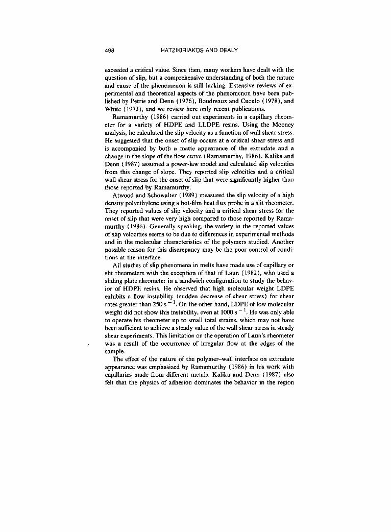
exceeded a critical value. Since then, many workers have dealt with the question of slip, but a comprehensive understanding of both the nature and cause of the phenomenon is still lacking. Extensive reviews of ex- perimental and theoretical aspects of the phenomenon have been pub- lished by Petrie and Denn (1976), Boudreaux and Cuculo (1978), and White ( 1973), and we review here only recent publications.
Ramamurthy (1986) carried out experiments in a capillary rheom- eter for a variety of HDPE and LLDPE resins. Using the Mooney analysis, he calculated the slip velocity as a function of wall shear stress. He suggested that the onset of slip occurs at a critical shear stress and is accompanied by both a matte appearance of the extrudate and a change in the slope of the flow curve (Ramamurthy, 1986). Kalika and Denn ( 1987) assumed a power-law model and calculated slip velocities from this change of slope. They reported slip velocities and a critical wall shear stress for the onset of slip that were significantly higher than those reported by Ramamurthy.
Atwood and Schowalter (1989) measured the slip velocity of a high density polyethylene using a hot-film heat flux probe in a slit rheometer. They reported values of slip velocity and a critical shear stress for the onset of slip that were very high compared to those reported by Rama- murthy ( 1986). Generally speaking, the variety in the reported values of slip velocities seems to be due to differences in experimental methods and in the molecular characteristics of the polymers studied. Another possible reason for this discrepancy may be the poor control of condi- tions at the interface.
All studies of slip phenomena in melts have made use of capillary or slit rheometers with the exception of that of Laun (1982), who used a sliding plate rheometer in a sandwich configuration to study the behav- ior of HDPE resins. He observed that high molecular weight LDPE exhibits a flow instability (sudden decrease of shear stress) for shear rates greater than 250 s - ‘. On the other hand, LDPE of low molecular weight did not show this instability, even at 1000 s - ‘. He was only able to operate his rheometer up to small total strains, which may not have been sufficient to achieve a steady value of the wall shear stress in steady shear experiments. This limitation on the operation of Laun’s rheometer was a result of the occurrence of irregular flow at the edges of the sample.
The effect of the nature of the polymer-wall interface on extrudate appearance was emphasized by Ramamurthy (1986) in his work with capillaries made from different metals. Kalika and Denn ( 1987) also felt that the physics of adhesion dominates the behavior in the region

WALL SLIP OF POLYETHYLENE 499
TABLE 1. Average molecular weights of resin 56B\ 3830.
Type of average or ratio Value
M” 19 ooo MU 177 800 ML 1061 600
M r+ I 1 875 500 I = MJM, 9.4
where small departures from the no-slip condition are encountered. It is this region that is of interest in the present work. Our objective was to study slip in the absence of entrance effects and with no pressure gra- dient, in particular to measure it as a function of shear stress and interface conditions. Obviously, a capillary or other pressure-driven flow could not be used.
EXPERIMENTAL
A sliding plate rheometer has been developed at McGill University that is capable of operating at both high shear rates and large total deformations (U.S. patents, 1984 and 1986; Giacomin et al., 1989). Making use of a “shear stress transducer, ” it can operate at steady shear rates from 0.05 to 500 s - ’ and total shear strains up to 500, because it measures the shear stress in the center of the sample, where edge effects are not a problem. The sliding plate geometry can be used effectively to study melt slip phenomena, because it generates a uniform flow field with no pressure gradient. Another advantage over capillary or slit rheometers is that it enables convenient modification and control of the polymer-wall interface.
The experiments were carried out on this sliding plate rheometer whose plates are made from type 420 stainless steel. Three gap spacings were used: 0.50.36, and 0.23 mm. The gap spacing was altered by using different high-precision spacing shims.
The polymer used was a high density polyethylene (56B\3830), manufactured by DuPont Canada. Table I lists several average molec- ular weights of this resin.
A Rheometrics mechanical spectrometer was used to measure the storage and loss moduli of the melt at several temperatures. Parallel disk geometry was used with a gap of 0.5 mm and strains ranging from 5% to 7%. Under these conditions the properties were found to be inde-

500 HATZIKIRIAKOS AND DEALY
1.000
r- RESIN MB\3830
1 A T=ZOO 'C, a,=1.648 0 T=185 'C, a,=1.323 El T=163 'C, a,=l.OOO C'
0.1 1.0 10.0 w%, rad/s
100.0
FIG. 1. Master curves of the loss and storage moduli ( 163 ‘C) of HDPE 56B\3830.
pendent of strain. Figure 1 shows the resulting master curves for the storage and loss moduli at a reference temperature of 163 “C. The shift factors for time-temperature superposition are indicated in the figure.
SLIP DURING STEADY SHEAR
Clean steel plates
Experiments at constant shear rate were performed at three gap spac- ings in order to determine the effect of the gap on the flow curve. The total strains required to achieve a constant value of the shear stress varied from 50 to 250. Before each run the plates were cleaned thor- oughly by using “Easy Off’ oven cleaner in order to keep them free of degraded polymer. In addition, before the sample was placed in the rheometer, the plates were rinsed several times with acetone.
Figure 2 shows the effect of the gap spacing on the nominal flow curve at 180 “C. The measured wall shear stress is plotted as a function of the “nominal” shear rate yn, which is defined as the ratio of the velocity of the moving plate to the spacing between the plates. Two

WALL SLIP OF POLYETHYLENE 501
0.20
0.10
T 20.08
b
0.06
0.04
RESIN 556\3830 T=l6dC
L3 h=0.23 mm 0 h=0.36 mm A h=OSO mm
5 10 50 100 500 h (s-7
FIG. 2. The effect of the gap spacing on the nominal flow curve of HDPE 56B\3830.
distinct regions may be observed from the nominal flow curves of Fig. 2. First is a power law region that extends up to a stress of approximately 0.09 MPa, in which the power law parameters are n = 0.44 and K = 0.0178 MPa s’.~. For shear stresses greater than the critical value of 0.09 MPa the nominal flow curves diverge and become gap depen- dent, exhibiting a change of slope. This change of slope is more pro- nounced for smaller gaps. These observations suggest that slip is occur- ring and that the Mooney analysis can be used to calculate the slip velocity as a function of shear stress.
In the sliding plate geometry both plates are thought to be identical under slip conditions. Therefore, it is assumed that the slip velocity is the same on both plates. This assumption will be examined in more detail later. It leads to the following relationship between the nominal and actual shear rates:
(1)

502 HATZIKIRIAKOS AND DEALY
600 - RESIN 56B\3630
T= 16O’C
500
400
7 z 300
.if
200
100
. x - 4
0
. :
. . - 0 . +
u=o. 17 MPa 0=0.16 MPa u=o.15 MPa u=O.14 MPa 0=0.13 MPa u=O.lZ MPa o=o. 1 I MPa u=O.lO MPe
X
4
0
x
+ .
8
1 2 3 4 5 l/h (mm-‘)
FIG. 3. Wall slip calculations for HDPE 56B\3830 at 180 “C.
where i/ ,, is the nominal shear rate, V is the velocity of the moving plate, p is the true shear rate in the melt, uS is the slip velocity, and h is the spacing between the plates. Equation (1) implies that a plot of p n vs l/h at constant shear stress will be a straight line whose slope is 2u,, if U, is a function of the shear stress (T. Figure 3 is a plot of i/ n vs l/h for several values of the shear stress. It can be observed that straight lines are obtained, which implies that the slip velocity does depend only on the shear stress.
Figure 4 shows the dependence of the slip velocity on shear stress at four temperatures. It can be observed that the slip velocity increases with temperature and that it is a nonlinear function of shear stress. Moreover, extrapolating the slip data for shear stresses less than 0.01 MPa, it can be observed that the slip velocity is approximately zero in the neighborhood of the critical shear stress of 0.09 MPa and that it increases smoothly with increasing shear stress. On this log-log plot

WALL SLIP OF POLYETHYLENE
1 RESIN 56B’ 3630
0 001
T=145’C T= 16O’C T= 16O’C T=ZOO’C T=lBO’C. Calculated using T=lBO’C. DFL sprey
0.08 0.10 SHEAR STRESS (MPa)
0.20
FIG. 4. Slip velocity as a function of wall shear stress on log-log plot to show power law for slip velocity.
most of the data for a given temperature and surface condition fall on a line, which suggests that a steady state slip model can be written as follows:
where uC is the critical shear stress, which is defined as the stress for the onset of melt slip. In the present case this critical shear stress has the value of 0.09 MPa. The slip coefficient a has units of m s - ’ (MPA) - m and seems to be a function of the temperature. Linear regression was used to calculate the exponent m and the slip coefficient (I for four temperatures, based on data involving stresses greater than 0.12 MPa. The results are summarized in Table II. The predictions of the slip model using the values of the parameters listed in Table II are plotted in Fig. 4 as continuous lines. It can be observed that the agreement with experimental data is very good except for stresses less than approxi- mately 0.12 MPa. The slip velocities for these stresses belong to a tran-

504 HATZIKIRIAKOS AND DEALY
TABLE II. Power-law constants for slip model.
m (I (ms-‘MPa-m) Correlation factor
145 “C 3.41 5.50 0.997 160°C 3.35 8.12 0.999 18O’C 3.29 11.05 0.998 200 “C 3.30 15.70 0.996 DFL spray 3.22 4.08 0.991 Dynamar 9613 3.03 59.22 0.995
sition region and do not follow the power law. This is to be expected, because the slip must go to zero at the critical stress. From Table II it can be seen that the exponent m is practically independent of temper- ature, while the parameter a depends fairly strongly on temperature.
Slip velocities can also be calculated by assuming that the u( i/ ) relationship for the material follows a power law when slip is occurring. Then one can use the nominal flow curve to calculate the slip velocity by use of Eq. (3):
2u,/h= f, - (q/K)“,
where K is the power law coefficient and n is the power-law index. This procedure was followed by Kalika and Denn (1987) to calculate slip velocities from their capillary rheometer data. Using IQ. (3), slip ve- locities were calculated from our sliding plate data, and these values are shown in Fig. 4, together with the slip velocities obtained using the Mooney analysis. It can be concluded that the polymer studied contin- ues to be a power-law fluid in the slip region, as the slip velocities obtained from the two methods are in good agreement.
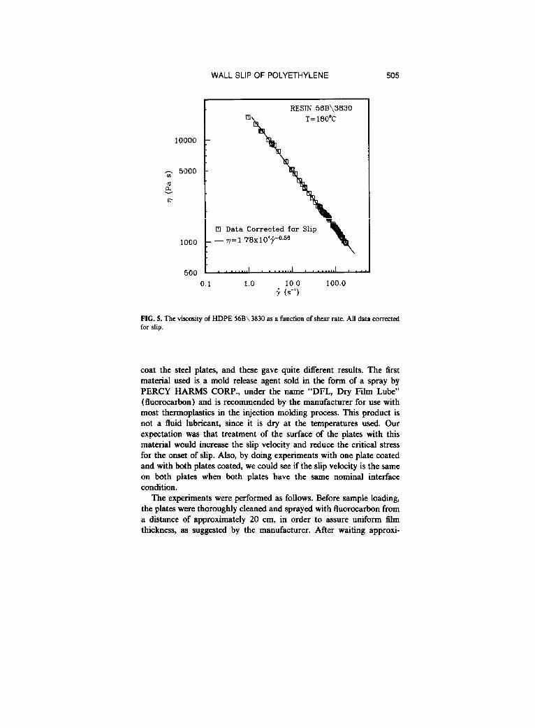
This can also be seen from Fig. 5 where the viscosity is plotted as a function of shear rate. The viscosity was calculated from the experimen- tal data, using Eq. (1) to determine the true shear rate. It can be observed that the polymer studied continues to follow the power law in the slip region so that all the data fall on a single line after having been corrected for slip.
Fluorocarbon-coated plates
In order to study the effect of the nature of the interface on slip, steady shear experiments were performed with one or both surfaces coated with a fluorocarbon. Two methods and materials were used to
WALL SLIP OF POLYETHYLENE 505
10000
3 5000
g 6
1000
500
cl Data
.- q=l
RESIN 56B\3830 II1 T= 1 BO’C
Corrected for Slip
0.1 1.0 10.0 100.0 f (s-7
FIG. 5. The viscosity of HDPE 56B\3830 as a function of shear rate. All data corrected for slip.
coat the steel plates, and these gave quite different results. The first material used is a mold release agent sold in the form of a spray by PERCY HARMS CORP., under the name “DFL, Dry Film Lube” (fluorocarbon) and is recommended by the manufacturer for use with most thermoplastics in the injection molding process. This product is not a fluid lubricant, since it is dry at the temperatures used. Our expectation was that treatment of the surface of the plates with this material would increase the slip velocity and reduce the critical stress for the onset of slip. Also, by doing experiments with one plate coated and with both plates coated, we could see if the slip velocity is the same on both plates when both plates have the same nominal interface condition.
The experiments were performed as follows. Before sample loading, the plates were thoroughly cleaned and sprayed with fluorocarbon from a distance of approximately 20 cm, in order to assure uniform film thickness, as suggested by the manufacturer. After waiting approxi-
506 HATZIKIRIAKOS AND DEALY
0.20 . T=160°C, h=0.36 mm - RESIN 56B\3630
0 0 0.16 - b q 0 A
0 D 00 * .4
0 DOA *
TO.12 - a o,%
D A q A
3 of@ .d
b 0.08
: -2--@
z ;Oum&TEEGr
Q MOVING PLATE TREATED 13 BOTH PLATES TReATED
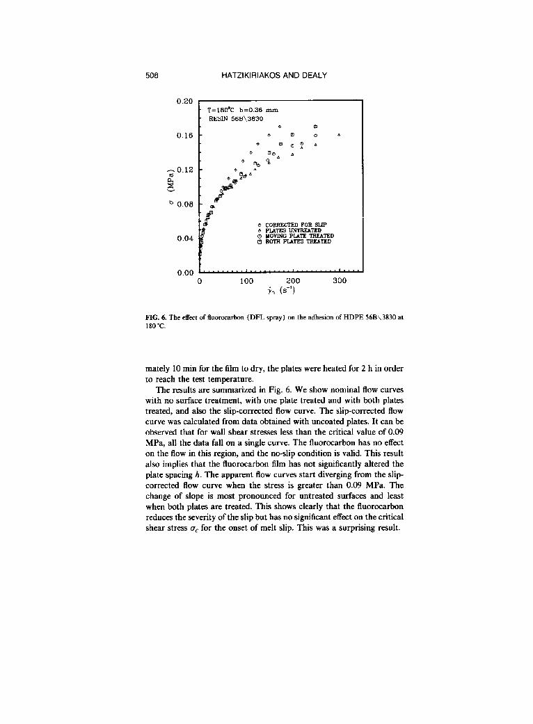
FIG. 6. The effect of fluorocarbon (DFL spray) on the adhesion of HDPE 56B\3830 at 180 "C.
mately 10 min for the film to dry, the plates were heated for 2 h in order to reach the test temperature.
The results are summarized in Fig. 6. We show nominal flow curves with no surface treatment, with one plate treated and with both plates treated, and also the slip-corrected flow curve. The slip-corrected flow curve was calculated from data obtained with uncoated plates. It can be observed that for wall shear stresses less than the critical value of 0.09 MPa, all the data fall on a single curve. The fluorocarbon has no effect on the flow in this region, and the no-slip condition is valid. This result also implies that the fluorocarbon film has not significantly altered the plate spacing h. The apparent flow curves start diverging from the slip- corrected flow curve when the stress is greater than 0.09 MPa. The change of slope is most pronounced for untreated surfaces and least when both plates are treated. This shows clearly that the fluorocarbon reduces the severity of the slip but has no significant effect on the critical shear stress a, for the onset of melt slip. This was a surprising result.
WALL SLIP OF POLYETHYLENE 507
Slip velocities were calculated using Eq. (3) and are shown in Fig. 4. It can be observed that the slip velocity for a treated surface is signiti- cantly less than that for a clean, untreated surface. For the case of one plate treated, it is not possible to calculate the slip velocity on each plate independently because the amount of slip is different on each plate. However, if 2r(,, the sum of the slip velocities on both plates in Pq. (3), is replaced by the sum of the slip velocities calculated independently from experiments with both plates clean and with both plates coated, the same corrected curve is obtained. This justifies our assumption that the melt slips on both plates by the same amount when both plates have been treated in the same way. The slip coefficient a and the exponent m for plates treated with fluorocarbon are listed in Table II. It can be concluded that m in the slip model does not depend on the conditions at the interface but that the slip coefficient a is strongly affected by these conditions.
These findings seem to support Ramamurthy’s conclusion that fluo- rocarbons reduce the severity of sharkskin in film blowing by promoting adhesion.
We pursued this question further by using a second material and procedure to coat the plates. This time we used a material that is actu- ally used as an additive to suppress sharkskin in film resins. This was Dynamar 9613, a 3M product. This fluorocarbon elastomer is in the form of a powder and was applied to the surface as follows. First, it was dissolved in acetone to yield a 1% solution. Some particles (probably inorganic) not soluble in acetone were allowed to precipitate, and the clarified solution was applied to the surface of the horizontally placed stationary plate. After the solvent had evaporated, the plate was heated to 230 “C for approximately 30 min in order for the coating to be sta- bilized. In addition, both plates were heated for approximately 2 h in order to reach the test temperature. The duration of each experiment was approximately 1 h.
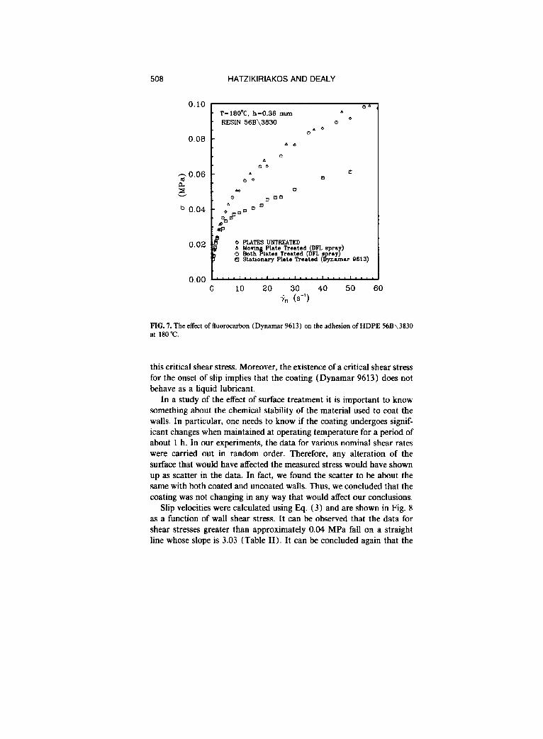
The results are summarized in Fig. 7. We again show nominal flow curves with no surface treatment, with one plate treated and with both plates treated with the fluorocarbon (DFL spray) and also the nominal flow curve with the stationary plate treated with the fluorocarbon Dy- namar 9613. It can be observed that for wall shear stresses less than approximately 0.025 MPa all the data fall on a single curve. However, for shear stresses greater than the critical shear stress of 0.025 MPa, the polymer slips at the polymer-wall interface treated with Dynamar 9613. Therefore, this elastomer severely reduces the critical shear stress for the onset of slip in contrast with the DFL spray, which had no effect on
508
0.10
HATZIKIRIAKOS AND DEALY
0.08 I T=180°C. h=0.36 RESIN 56B\3830
P 0 PLATES UNTREATED 0
0 10 20 40 50 60
FIG. 7. The effect of fluorocarbon (Dynamar 9613) on the adhesion of HDPE 56B\3830 at 180°C.
this critical shear stress. Moreover, the existence of a critical shear stress for the onset of slip implies that the coating (Dynamar 9613) does not behave as a liquid lubricant.
In a study of the effect of surface treatment it is important to know something about the chemical stability of the material used to coat the walls. In particular, one needs to know if the coating undergoes signif- icant changes when maintained at operating temperature for a period of about 1 h. In our experiments, the data for various nominal shear rates were carried out in random order. Therefore, any alteration of the surface that would have affected the measured stress would have shown up as scatter in the data. In fact, we found the scatter to be about the same with both coated and uncoated walls. Thus, we concluded that the coating was not changing in any way that would affect our conclusions.
Slip velocities were calculated using Eq. (3) and are shown in Fig. 8 as a function of wall shear stress. It can be observed that the data for shear stresses greater than approximately 0.04 MPa fall on a straight line whose slope is 3.03 (Table II). It can be concluded again that the

WALL SLIP OF POLYETHYLENE 509
0.04 0.05 0.06 0.07 SHEAR STRESS (MPa)
FIG. 8. Slip velocity as a function of wall shear stresses for surface treated with Dynamar 9613 at 1BO”C.
m in the slip model does not depend on the conditions at the interface but that the slip coefficient a is strongly affected by these conditions (Table II).
We cannot comment further on the difference between the results for the two coating materials, as the precise composition of the DFL spray is not known. However, comments on Ramamurthy’s hypothesis that fluoroelastomer acts as an adhesion promoter are in order. In fact, he saw no effect of fluoroelastomer on his capillary results and attributed this to the fact that there was inadequate time for the additive to coat the wall of the capillary die. Furthermore, in his film die studies, only the extrudate surface was observed, as it was not possible to measure wall slip velocities. His conclusion as to the role played by the resin additive was based primarily on an experiment in which pure fluoroclas- tomer was extruded through a capillary and showed no evidence of slip. We believe that this is inconclusive, as it is possible that the fluoroelas- tomer remains adhered to the steel while allowing slip at its interface with the polyethylene.
510 HATZIKIRIAKOS AND DEALY
TRANSIENT SHEAR EXPERIMENTS
Exponential shear
The relationship between the slip velocity and shear stress presented above [Eq. (2)] is based on steady shear data, and it may not be valid for transient shear. For example, hysteresis phenomena have been ob- served in dynamic experiments when elastomers slide over metal sur- faces, and various dynamic models have been proposed to predict the transient slip behavior of these materials (Moore and Geyer, 1974). Vinogradov et al. ( 1972) studied slip in melts and interpreted their results in terms of a “forced high elastic state” that facilitates slip at high shear stresses. The behavior of melts at high rates of deformation thus may resemble that of elastomers, and a dynamic slip model might then account for hysteresis effects.
Lim and Schowalter (1990) suggested that the transition from the slip to the stick condition in the oscillating flow region of the flow curve for slit flow was gradual and showed characteristics of a relaxation process. They also reported that the relaxation time for this process was a decreasing function of shear rate. To incorporate such a relaxation process into a dynamic slip model that is also consistent with our steady state observations [Eq. (2)] we propose the following:
u5 + As ( duJdt) = au”, (4)
where As is a “slip relaxation time.” For steady slip flow the second term on the left-hand side of Eq. (4) is zero, and Eq. (2) is thus recovered.
The validity of Eq. (4) was studied, and the slip relaxation time A, was estimated by observing slip in a transient flow. Exponential shear was chosen as the transient flow. This “strong flow” has been discussed in detail by Doshi and Dealy ( 1987). The strain varies with time as follows:
y,=A(ea’- I), (5)
where A is the “strain scale factor” and a is the “exponential rate constant.” Figure 9 shows experimental data for a specific exponential shear history with A = 0.1 and a = 5 s - ’ for three gap spacings. It can be observed that at shear stresses less than 0.09 MPa the three transient curves define approximately a single curve. For stresses less than the critical value of 0.09 MPa the maximum relative difference in stress increases to 5% and then drops to approximately 3% for stresses in the neighborhood of 0.09 MPa. These small deviations are considered to be within experimental error. However, for shear stresses greater than 0.09

WALL SLIP OF POLYETHYLENE 511
0.15
RESIN 56B\3630 RESIN 56B\3630 T= 16O’C T= 16O’C
- --h=0.23 mm - --h=0.23 mm ... h=0.36 mm ... h=0.36 mm - h=0.50 mm - h=0.50 mm
20.10
z5 b
Exponential Exponential Shear
y=0.1(e5’ -1)
0.05
0.00
0 10 20 30 40 50 60 Y
FIG. 9. The effect of the gap spacing on an exponential shear experiment at 180 “C. The deformation history is given in terms of strain.
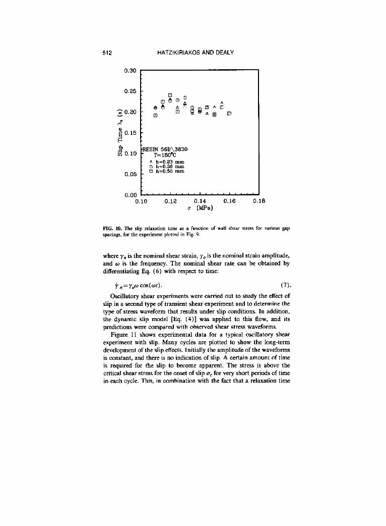
MPa these curves diverge, and the differences between them steadily increase and are considered to be beyond experimental error. Following the same method as for steady shear [Eq. ( 1)], the slip velocity was calculated as a function of shear stress. In addition, from this relation- ship the slip velocity as a function of time could be inferred. Using Eq. (4), values of the slip relaxation time at various values of wall shear stress were calculated and are plotted in Fig. 10. It can be seen that the slip relaxation time is approximately constant and is in the range of 0.19-0.25 s. Therefore, a mean value of 0.22 s was used for the calcu- lations described in the next section.
Oscillatory shear
For oscillatory shear the nominal shear strain as a function of time is
y,(t)=y,sin(d, (6)
512 HATZIKIRIAKOS AND DEALY
2
g 0.15 - .G a -RESIN 56Ei\3630
ij 0.10 - T=160°C
. A h=0.23 mm
. 0 h=0.38 mm
. 13 h=0.50 mm 0.05 -
t 0.00 1
0.10 0.12 0.14 0.16 0.16 c (ma)
FIG. 10. The slip relaxation time as a function of wall shear stress for various gap spacings, for the experiment plotted in Fig. 9.
where ‘y,, is the nominal shear strain, yO is the nominal strain amplitude, and o is the frequency. The nominal shear rate can be obtained by differentiating Eq. (6) with respect to time:
y.=y&l cos(wr). (7).
Oscillatory shear experiments were carried out to study the effect of slip in a second type of transient shear experiment and to determine the type of stress waveform that results under slip conditions. In addition, the dynamic slip model [IQ. (4)] was applied to this flow, and its predictions were compared with observed shear stress waveforms.
Figure 11 shows experimental data for a typical oscillatory shear experiment with slip. Many cycles are plotted to show the long-term development of the slip effects. Initially the amplitude of the waveforms is constant, and there is no indication of slip. A certain amount of time is required for the slip to become apparent. The stress is above the critical shear stress for the onset of slip gC for very short periods of time in each cycle. This, in combination with the fact that a relaxation time

WALL SLIP OF POLYETHYLENE 513
0.1 3 3 0.0 b
-0.1
-0.2 0 5 10 15 20
Time (9) 0.2
0.1 3 ,sj 0.0
b -0.1
-0.2 . * * * ’ . . . . ’ * * * * ’ * * . . 20 25 30 35 40
Time (s)
FIG. 11. A typical large amplitude oscillatory shear experiment exhibiting wall slip and a gradual change of the adhesion characteristics of the interface at 180°C.
is involved in the melt slip process, is not enough to cause slip. In spite of the fact that the adhesive bonds are subject to high stresses, these are able to keep the molecules attached to the wall for short periods of time. However, these bonds cannot withstand the high stresses after succes- sive cycles, and the polymer starts slipping. As a result, the amplitude of the shear stress waves decreases as shown in Fig. 11. This decrease is gradual, and after a certain number of cycles a quasi-steady state is established.
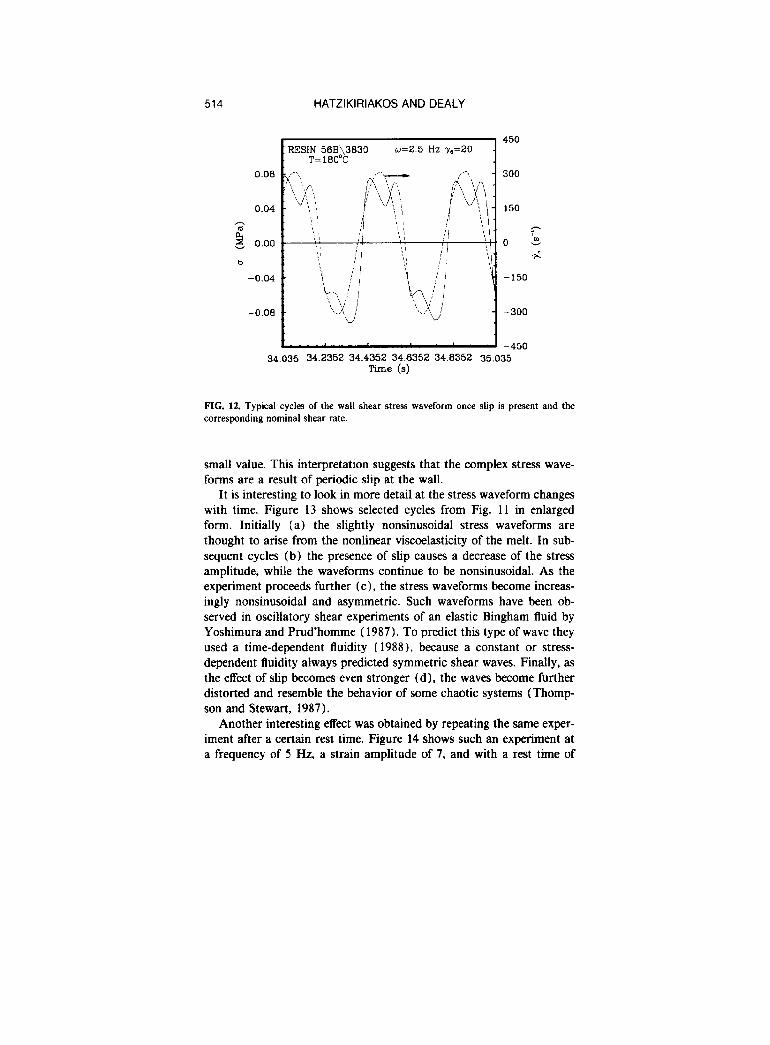
Figure 12 shows a few typical cycles of the shear stress waveform from the experiment of Fig. 11 in expanded form along with the corre- sponding nominal shear rate waveform. The time is measured from the beginning of the experiment. At a certain point of the cycle the polymer appears to lose its adhesion, and the shear stress starts decreasing. How- ever, as the nominal shear rate decreases the polymer regains adhesion, and the stress increases again until the nominal shear rate assumes a
514 HATZIKIRIAKOS AND DEALY
-450 34.035 34.2352 34.4352 34.6352 34.6352 35.035
Time (s)
: RESIN 56B\3630 w=2.5 Hz -yo=ZO . T=160°C
450
FIG. 12. Typical cycles of the wall shear stress waveform once slip is present and the corresponding nominal shear rate.
small value. This interpretation suggests that the complex stress wave- forms are a result of periodic slip at the wall.
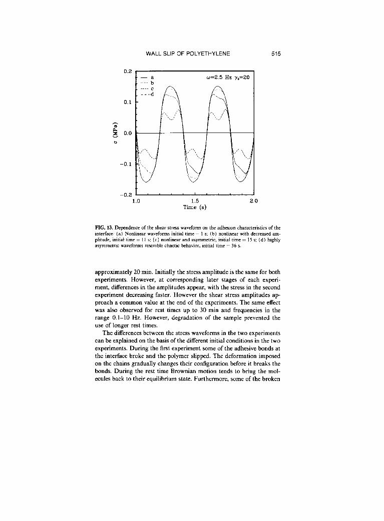
It is interesting to look in more detail at the stress waveform changes with time. Figure 13 shows selected cycles from Fig. 11 in enlarged form. Initially (a) the slightly nonsinusoidal stress waveforms are thought to arise from the nonlinear viscoelasticity of the melt. In sub- sequent cycles (b) the presence of slip causes a decrease of the stress amplitude, while the waveforms continue to be nonsinusoidal. As the experiment proceeds further (c) , the stress waveforms become increas- ingly nonsinusoidal and asymmetric. Such waveforms have been ob- served in oscillatory shear experiments of an elastic Bingham fluid by Yoshimura and Prud’homme (1987). To predict this type of wave they used a time-dependent fluidity (19881, because a constant or stress- dependent fluidity always predicted symmetric shear waves. Finally, as the effect of slip becomes even stronger (dl, the waves become further distorted and resemble the behavior of some chaotic systems (Thomp- son and Stewart, 1987).
Another interesting effect was obtained by repeating the same exper- iment after a certain rest time. Figure 14 shows such an experiment at a frequency of 5 Hz, a strain amplitude of 7, and with a rest time of
WALL SLIP OF POLYETHYLENE 515
2 g 0.0
b
w=2.5 Hz y0=20
1.0 1.5 Time (s)
2.0
FIG. 13. Dependence of the shear stress waveform on the adhesion characteristics of the interface: (a) Nonlinear waveforms initial time = 1 s; (b) nonlinear with decreased am- plitude. initial time = 11 s; (c) nonlinear and asymmetric, initial time = 15 s; (d) highly asymmetric waveforms resemble chaotic behavior, initial time = 36 s.
approximately 20 min. Initially the stress amplitude is the same for both experiments. However, at corresponding later stages of each experi- ment, differences in the amplitudes appear, with the stress in the second experiment decreasing faster. However the shear stress amplitudes ap- proach a common value at the end of the experiments. The same effect was also observed for rest times up to 30 min and frequencies in the range 0.1-10 Hz. However, degradation of the sample prevented the use of longer rest times.
The differences between the stress waveforms in the two experiments can be explained on the basis of the different initial conditions in the two experiments. During the first experiment some of the adhesive bonds at the interface broke and the polymer slipped. The deformation imposed on the chains gradually changes their configuration before it breaks the bonds. During the rest time Brownian motion tends to bring the mol- ecules back to their equilibrium state. Furthermore, some of the broken

516 HATZIKIRIAKOS AND DEALY
0.15 ’ - Initial test w=5 Hz y0=7 . . ..After 20 min. rest time
3 0.05
5
b 0.00
-0.05
-0.10
FIG. 14. Two identical experiments with a rest time of 20 min between them. The adhesion characteristics change faster in the second experiment. However, initially (b) and finally (c) stress amplitudes are the same.
bonds, if not all, are reestablished. However, the rest time is not enough to bring the chains attached to the wall into their original configuration. Preoriented molecules can be more easily detached from the surface than those that have a random orientation.
In order to apply the dynamic slip model to oscillatory shear to predict the form of the stress waveform, we need a constitutive equation to relate the stress to the deformation of the bulk polymer. A linear viscoelastic constitutive equation was chosen so that any anharmonicity in the stress waveform would be associated with slip effects alone and not with nonlinear viscoelasticity. For purposes of this phenomenolog- ical study we used a Maxwell model with one relaxation time:
a+d(du/dt)=q,j, (8)
where vO is the zero shear viscosity. The true shear rate can be calcu- lated from the nominal shear rate and slip velocity via Eq. ( 1). Com- bining Eqs. (1) and (7) with Eq. (8) to eliminate i,, the following equation is obtained:
a+~(do/dt)=77,[y,wcos(ot) -2uJh]
WALL SLIP OF POLYETHYLENE 517
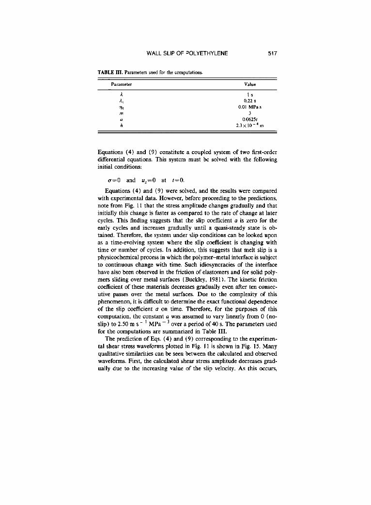
TABLE III. Parameters used for the computations.
Parameter Value
A 4 To m (1 h
Is a.22 s
0.01 MPas 3
0.0625r 2.3~ 10m4 m
Equations (4) and (9) constitute a coupled system of two first-order differential equations. This system must bc solved with the following initial conditions:
o=O and u,=O at t=O.
Equations (4) and (9) were solved, and the results were compared with experimental data. However, before proceeding to the predictions, note from Fig. 11 that the stress amplitude changes gradually and that initially this change is faster as compared to the rate of change at later cycles. This finding suggests that the slip coefficient n is zero for the early cycles and increases gradually until a quasi-steady state is ob- tained. Therefore, the system under slip conditions can be looked upon as a time-evolving system where the slip coefficient is changing with time or number of cycles. In addition, this suggests that melt slip is a physicochemical process in which the polymer-metal interface is subject to continuous change with time. Such idiosyncracies of the interface have also been observed in the friction of elastomers and for solid poly- mers sliding over metal surfaces (Buckley, 1981). The kinetic friction coefficient of these materials decreases gradually even after ten consec- utive passes over the metal surfaces. Due to the complexity of this phenomenon, it is difficult to determine the exact functional dependence of the slip coefficient a on time. Therefore, for the purposes of this computation, the constant a was assumed to vary linearly from 0 (no- slip) to 2.50 m s - ’ MPa - 3 over a period of 40 s. The parameters used for the computations are summarized in Table III.
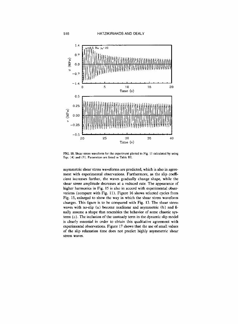
The prediction of Eqs. (4) and (9) corresponding to the experimen- tal shear stress waveforms plotted in Fig. 11 is shown in Fig. 15. Many qualitative similarities can be seen between the calculated and observed waveforms. First, the calculated shear stress amplitude decreases grad- ually due to the increasing value of the slip velocity. As this occurs,
518 HATZIKIRIAKOS AND DEALY
0.7
‘;f;
2 0.0
b -0.7
-1.4 r”~‘....I,l,.,
0 5 10 15 20 Time (s)
-0.5 1 ’ ’ . ’ ’ * * ’ . ’ ’ I . . . . 20 25 30 35 40
Time (s)
PIG. 15. Shear stress waveform for the experiment plotted in Fig. 11 calculated by using Eqs. (4) and (9). Parameters are listed in Table III.
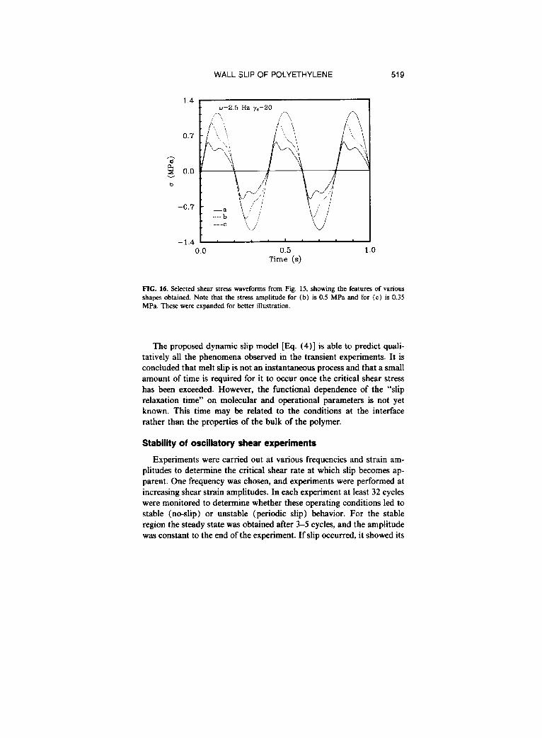
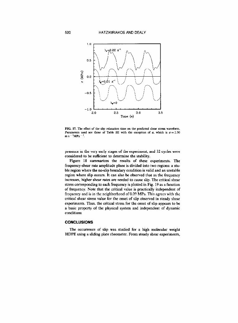
asymmetric shear stress waveforms are predicted, which is also in agree- ment with experimental observations. Furthermore, as the slip coeffi- cient increases further, the waves gradually change shape, while the shear stress amplitude decreases at a reduced rate. The appearance of higher harmonics in Fig. 15 is also in accord with experimental obser- vations (compare with Fig. 11). Figure 16 shows selected cycles from Fig. 15, enlarged to show the way in which the shear stress waveform changes. This figure is to be compared with Fig. 13. The shear stress waves with no-slip (a) become nonlinear and asymmetric (b) and fi- nally assume a shape that resembles the behavior of some chaotic sys- tems (c). The inclusion of the unsteady term in the dynamic slip model is clearly essential in order to obtain this qualitative agreement with experimental observations. Figure 17 shows that the use of small values of the slip relaxation time does not predict highly asymmetric shear stress waves.
WALL SLIP OF POLYETHYLENE 519
w=2.5 Hz y,=20
0.5 Time (s)
FIG. 16. Selected shear stress waveforms from Fig. 15, showing the features of various shapes obtained. Note that the stress amplitude for (b) is 0.5 MPa and for (c) is 0.35 MPa. These were expanded for better illustration.
The proposed dynamic slip model [Eq. (4)] is able to predict quali- tatively all the phenomena observed in the transient experiments. It is concluded that melt slip is not an instantaneous process and that a small amount of time is required for it to occur once the critical shear stress has been exceeded. However, the functional dependence of the “slip relaxation time” on molecular and operational parameters is not yet known. This time may be related to the conditions at the interface rather than the properties of the bulk of the polymer.
Stability of oscillatory shear experiments
Experiments were carried out at various frequencies and strain am- plitudes to determine the critical shear rate at which slip becomes ap- parent. One frequency was chosen, and experiments were performed at increasing shear strain amplitudes. In each experiment at least 32 cycles were monitored to determine whether these operating conditions led to stable (no-slip) or unstable (periodic slip) behavior. For the stable region the steady state was obtained after 3-5 cycles, and the amplitude was constant to the end of the experiment. If slip occurred, it showed its
520 HATZIKIRIAKOS AND DEALY
-1.0 b 2.0 2.5 3.0 3.5
Time (s)
FIG. 17. The effect of the slip relaxation time on the predicted shear stress waveform. Parameters used are those of Table III with the exception of II, which is (I = 2.50 ms - ‘MPa - ‘.
presence in the very early stages of the experiment, and 32 cycles were considered to be sufficient to determine the stability.
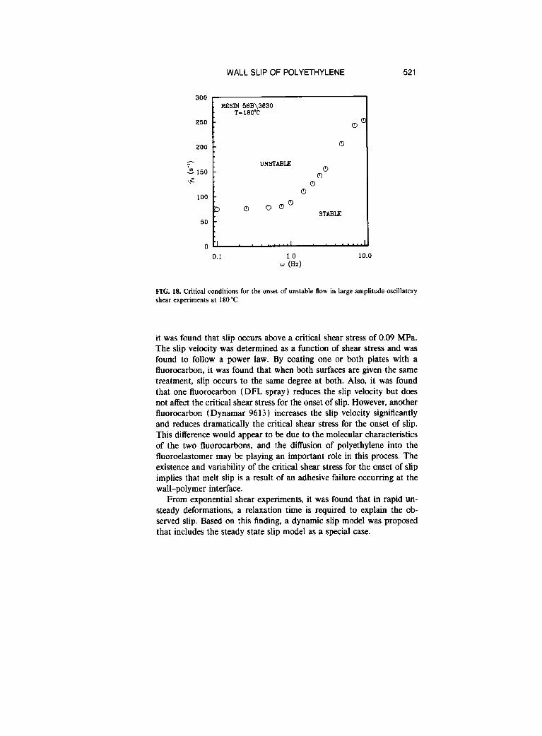
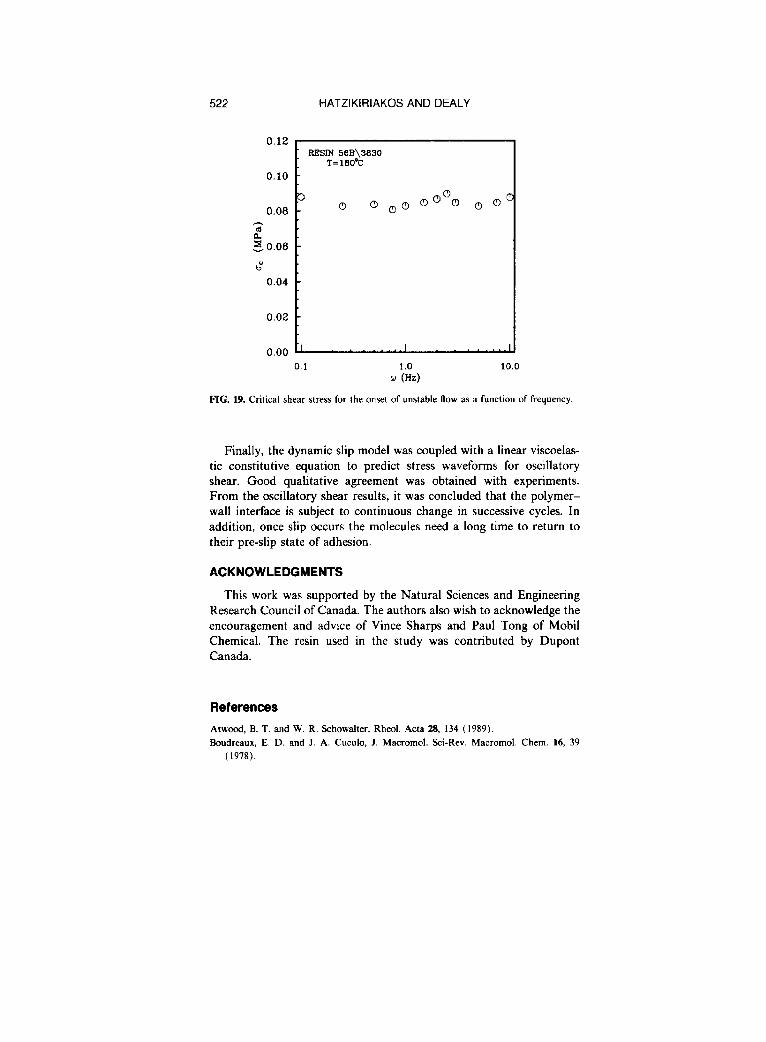
Figure 18 summarizes the results of these experiments. The frequency-shear rate amplitude plane is divided into two regions: a sta- ble region where the no-slip boundary condition is valid and an unstable region where slip occurs. It can also be observed that as the frequency increases, higher shear rates are needed to cause slip. The critical shear stress corresponding to each frequency is plotted in Fig. 19 as a function of frequency. Note that the critical value is practically independent of frequency and is in the neighborhood of 0.09 MPa. This agrees with the critical shear stress value for the onset of slip observed in steady shear experiments. Thus, the critical stress for the onset of slip appears to be a basic property of the physical system and independent of dynamic conditions.
CONCLUSIONS
The occurrence of slip was studied for a high molecular weight HDPE using a sliding plate rheometer. From steady shear experiments,
WALL SLIP OF POLYETHYLENE 521
250
200
,” L 150 .G
100
50
0
. RESIN %3El\3830 T=lSO’C
oc
0
I I CL
0.1 1.0 10.0 w (Hz)
FIG. 18. Critical conditions for the onset of unstable flow in large amplitude oscillatory shear experiments at 180 “C.
it was found that slip occurs above a critical shear stress of 0.09 MPa. The slip velocity was determined as a function of shear stress and was found to follow a power law. By coating one or both plates with a fluorocarbon, it was found that when both surfaces are given the same treatment, slip occurs to the same degree at both. Also, it was found that one fluorocarbon (DFL spray) reduces the slip velocity but dots not affect the critical shear stress for the onset of slip. However, another fluorocarbon (Dynamar 9613) increases the slip velocity significantly and reduces dramatically the critical shear stress for the onset of slip. This difference would appear to be due to the molecular characteristics of the two fluorocarbons, and the diffusion of polyethylene into the fluoroelastomer may be playing an important role in this process. The existence and variability of the critical shear stress for the onset of slip implies that melt slip is a result of an adhesive failure occurring at the wall-polymer interface.
From exponential shear experiments, it was found that in rapid un- steady deformations, a relaxation time is required to explain the ob- served slip. Based on this finding, a dynamic slip model was proposed that includes the steady state slip model as a special case.
522
0.12
PIG. 19. Critical shear stress for the onset of unstable flow as a function of frequency.
0.10
0.08
b” 0.04
0.02
0.00
HATZIKIRIAKOS AND DEALY
. RESIN 56B\3EI30 T=180°C
0.1 1 .o 10.0 w (Hz)
Finally, the dynamic slip model was coupled with a linear viscoelas- tic constitutive equation to predict stress waveforms for oscillatory shear. Good qualitative agreement was obtained with experiments. From the oscillatory shear results, it was concluded that the polymer- wall interface is subject to continuous change in successive cycles. In addition, once slip occurs the molecules need a long time to return to their pre-slip state of adhesion.
ACKNOWLEDGMENTS
This work was supported by the Natural Sciences and Engineering Research Council of Canada. The authors also wish to acknowledge the encouragement and advice of Vince Sharps and Paul Tong of Mobil Chemical. The resin used in the study was contributed by DuPont Canada.
References
Atwood, B. T. and W. R. Schowaher, Rheol. Acta 28, 134 (1989). Boudreaux, E. D. and J. A. Cuculo, J. Macromol. &i-Rev. Macromol. Chem. 16, 39
(1978).
WALL SLIP OF POLYETHYLENE 523
Buckley, D. H., Surface Effecrs ,n Adhesion, Friction, Wear, and Lubrication (Elsevier, New York, 1981).
Doshi, S. R. and J. M. Dealy, J. Rheol. 31, 563 (1987). Glacomin, A. J., T. Samurkas, and I. M. Dealy, Polym. Eng. Sci. 29, 499 [ 1989). Kalika, D. S. and M. M. Denn, J. Rheol. 31, 815 (1987). Laun, H. M., Rheol. Acta 21, 464 (1982). Lim, F. J. and W. R Schowalter, J. Rheol. 33, 1359 (1989). Mooney, M., J. Rheol. 2, 210 (1931). Moore, D. F. and W. Geyer, Wear 30, I (1974). P&e, C. J. S. and M. M. Denn, AIChEJ 22, 209 (1976). Ramamurthy, A. V., J. Rheol. 30, 337 ( 1986). Thompson, J. M. T. and H. B. Stewart, No&near Dynamics and Chaos (Wiley, New
York, 1987). Tordella, in Rheofogv, edited by F. R. Eirich (Academic, New York, 1969), Vol. 5, p. 57. U.S. patents: 4,463,928 (1984) and 4,57 1,989 (1986). Vinogradov, G. V., N. I. Insarova. B. B. Boiko, and E. K. Borinsekova, Polym. Eng. Sci.
12, 323 (1972). White, J. L., Appl. Polym. Symp. 20, 155 (1973). Yoshimura, A. S. and R. K. Prud’homme, Rheol. Acta 26, 428 (1987). Yoshimura, A. S. and R. K. Prud’homme, J. Rheol. 32, 575 (1988).