WALL OR WINDOW EXTRACT FANS HV-STYLVENT Series · 2015-08-17 · Wall or window extract fans ......
7
HV-STYLVENT Wall or window extract fans Complete range of axial flow fans for wall or window mounting applications. All the fans are supplied with tough ABS plastic grilles, shutter and single phase 230V- 50Hz motor. All the fans are class II insulation and IPX4 rated. The HV-STYLVENT series comprises of 3 diam- eters: 150, 230 and 300 mm, including several operating options, making them ideally suited for a wide range of general residential, commer- cial and industrial exhaust or supply ventilation applications. WALL OR WINDOW EXTRACT FANS HV-STYLVENT Series Shutter To prevent air entry and limit heat leakage when the extractor is not operating Natural ventilation position Shutter open, fan off Extract or supply operation Reversible Elegant design harmonising with any environment
Transcript of WALL OR WINDOW EXTRACT FANS HV-STYLVENT Series · 2015-08-17 · Wall or window extract fans ......

HV
-ST
YLV
EN
TW
all o
r w
ind
ow
ext
ract
fan
s
Complete range of axial flow fans for wall or
window mounting applications. All the fans are
supplied with tough ABS plastic grilles, shutter
and single phase 230V- 50Hz motor. All the fans
are class II insulation and IPX4 rated.
The HV-STYLVENT series comprises of 3 diam-
eters: 150, 230 and 300 mm, including several
operating options, making them ideally suited
for a wide range of general residential, commer-
cial and industrial exhaust or supply ventilation
applications.
WALL OR WINDOW EXTRACT FANS
HV-STYLVENT Series
Shutter
To prevent air entry and limit
heat leakage when the extractor
is not operating
Natural ventilation position
Shutter open, fan offExtract or supply operation
Reversible
Elegant design harmonising with any environment

HV
-ST
YLV
EN
TW
all o
r w
ind
ow
ext
ract
fan
s
HV- AE versions
Manually operated models via integral pull cord
- Single speed (HV-150M) or 2-speed (HV-230M and 300M) operation- Model 230 and 300 are reversible- Natural ventilation position (shutter open, fan off - except HV-150M)- Neon lights indicating the mode of operation
HV-150 M: 2 Positions: Fan OFF, shutter closed Fan ON, working as air extract with shutter open
HV-230 M: 5 Positions:HV-300 M 1-Fan stopped and shutter closed 2-Fan on high speed working as air extract with shutter open 3-Fan on low speed working as air extract with shutter open 4-Fan stopped and shutter open 5-Fan in reverse high speed supplying air in the room with shutter open
HV-M versions
Automatic models operated via control unit CR
- Single speed (HV-150A) or 2-speed (HV-230A and 300A) operation- Model 230 and 300 are reversible- Natural ventilation position (shutter open, fan off)- Neon lights indicating the mode of operation
HV-150 A: 3 Positions: - Fan OFF, shutter closed - Fan OFF, shutter open - Fan ON, working as air extract To operate all these functions use the accessory CR-150
HV-230 A: 5 Positions:HV-300 A 1-Fan stopped and shutter closed 2-Fan on high speed working as air extract with shutter open 3-Fan on low speed working as air extract with shutter open 4-Fan stopped and shutter open 5-Fan in reverse high speed supplying air in the room with shutter open To operate all these functions use the accessory CR-300
HV-A versions
Standard range
- Single-phase motor 230V50Hz with thermal overload protection- Single speed operation- Class II insulation- Model 230 and 300 are reversible with CR-150 control accessory- Automatic, thermally actuated shutter
HV-150 AE: 2 Positions: OFF - Fan OFF, shutter closed ON - fan ON, working as air extract with shutter open
HV-230 AE: 3 positions (with CR-150 control accessory)HV-300 AE OFF - Fan OFF/Shutter closed ON - Fan ON/shutter open Fan working as air extract/supplying air
REB-1R control: Speed controller including a switch to reverse the airflow direction

HV
-ST
YLV
EN
TW
all o
r w
ind
ow
ext
ract
fan
s
Model Flush Single Two Natural Pull Electrical accessories Radio mounted speed speed Reversible ventilation cord REB-1R CR-150 CR-300 control
HV-150 M • •
HV-230 M • • • •
HV-300 M • • • •
HV-150 AE • •
HV-230 AE • • • •
HV-300 AE • • • •
HV-150 A • • •
HV-230 A • • • •
HV-300 A • • • •
HV-230 RC • • • • HV-300 RC • • • • HVE-230 AE • • • •
HVE-230 A • • • • • HVE-230 RC • • • • •
Maximum ambient operating temperature for all models: 45ºC.One remote control can operate several HV.RC. In that case, the fans must be installed with a minimum distance of 1,5 meters between fans.
STYLVENT Product Summary – Operational Specifications
Radio control range
- Two speed operation- Natural ventilation position- All model are reversible- Automatic, thermally actuated shutter- Neon light mode of operation indication
HV-230 RC: 6 Positions:HV-300 RC 1-Fan stopped and shutter open 2-Fan stopped and shutter closed 3-Fan on high speed working as air extract with shutter open 4-Fan on reverse high speed supplying air in the room with shutter open 5-Fan on low speed working as air extract with shutter open 6-Fan in reverse low speed supplying air in the room with shutter open
HV-RC versions
Flush mounted version
HVE-230 AE: 3 same positions that HV-230 AEHVE-230 A: 5 same positions that HV-230 AHVE-230 RC: 6 same positions that HV-230 RC
HVE versions

HV
-ST
YLV
EN
TW
all o
r w
ind
ow
ext
ract
fan
s
Technical characteristics
Dimensions (mm)
G
F
B
C
E
Ø D
A
H
(no vidro)
Model A B C ø D E F G H
Min. Max. Min. Max. Min. Min.
HV-150 230 251 109 187 190 3 25 22 160 150
HV-230 300 325 142 259 262 3 25 22 200 185
HV-300 368 403 150 327 330 3 25 22 230 220
on the glass
163
173 182356
326
367
337
Dimensions of the HVE “flush mounted” version
Model Speed
(tr/mn)
Maximum absorbed
power
(W)
Maximumabsorbedcurrent
(A)
Airflow rate (m3/h) Sound pressure level at 3 m (dB(A))
Weight
(kg)
ExtractionIntake
High speed
Low speed
High speed
Low speed
HV-150 AE 1800 32 0,19 225 - - 39 - 2,0
HV-150 M 1800 32 0,19 225 - - 39 - 2,0
HV-150 A 1800 32 0,19 225 - - 39 - 2,0
HV-230 AE 1250 34 0,15 600 - 330 43 - 3,5
HVE-230 AE 1250 34 0,15 600 - 330 43 - 3,5
HV-230 M 1250 34 0,15 600 450 330 43 37 3,5
HV-230 A 1250 34 0,15 600 450 330 43 37 3,5
HVE-230 A 1250 34 0,15 600 450 330 43 37 3,5
HV-230 RC 1250 34 0,15 600 450 330 43 37 3,5
HVE-230 RC 1250 34 0,15 600 450 330 43 37 3,5
HV-300 AE 1150 68 0,30 1100 - 700 46 - 5,1
HV-300 M 1150 68 0,30 1100 750 700 46 38 5,1
HV-300 A 1150 68 0,30 1100 750 700 46 38 5,1
HV-300 RC 1150 68 0,30 1100 750 700 46 38 5,1

HV
-ST
YLV
EN
TW
all o
r w
ind
ow
ext
ract
fan
s
Fast and simple three stage installation
Installation in glass or panels from 3 to 25 mm thickness
The STYLVENT series of fans are designed for
speed of installation in three easy stages.
Stage 1 - External grille
Once in position, the external grille is held by
three rubber plugs which allow the installer to
assemble the interior section of the fan.
Stage 2 - Support frame
To enable easy mounting of the support frame,
the holes are tapered and the fixing screws can
be located depending on the glass/panel thic-
kness:
3 mm< thickness<10 mm
10 mm<thickness<25 mm
Stage 3 – Internal grille
Finally, place the lugs on the top of the support
frame into the rectangular slots on the front
grille it into position.
For a wall mounted installation it is necessary to use the extended threaded rod set (see Installation accessories) Installation on walls from 25 to 300 mm thick
Before installation, rods must be cut to 5mm
less than the thickness of the wall. Cut a hole
in the wall in accordance with the dimensions
shown in the table (to right).
Ensure that internal wall mounting surface is as
smooth as possible.
On the interior of the wall, mark the fixing
hole positions using the support plate as a
template.
Fit the threaded rods to the external guard
using the threaded sleeves. Place the external
grille into position and hold in place with the
rubber plugs.
Then, the installation follows the same sta-
ges as in the glass installation except for the
support frame installation, which has to be
fixed using 2 or 4 screws (HV-150, HV-230 and
HV-300 models respectively).
Model Ø D H* L*
Min. Max.
HV-150 187 190 117 121
HV-230 259 262 152 165
HV-300 327 330 322,5 357,3
* There are only two diagonal fixing holes for model HV-150.
H
L
Ø D
HV
-ST
YLV
EN
TW
all o
r w
ind
ow
ext
ract
fan
s
8
0
0
m3/h
m3/sQ
Pa P mmWG
0
7
5
6
4
3
2
1
20
30
40
50
60
70
80
200 400 60 800 1000
0,05 0,1 0,15
Pst
90
1
2
3
0
0,2 0,25 0,3
HV-300
10
9
1200
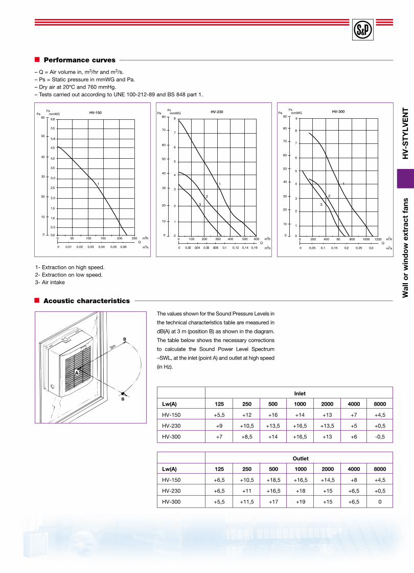
Acoustic characteristics
Inlet
Lw(A) 125 250 500 1000 2000 4000 8000
HV-150 +5,5 +12 +16 +14 +13 +7 +4,5
HV-230 +9 +10,5 +13,5 +16,5 +13,5 +5 +0,5
HV-300 +7 +8,5 +14 +16,5 +13 +6 -0,5
Outlet
Lw(A) 125 250 500 1000 2000 4000 8000
HV-150 +6,5 +10,5 +18,5 +16,5 +14,5 +8 +4,5
HV-230 +6,5 +11 +16,5 +18 +15 +6,5 +0,5
HV-300 +5,5 +11,5 +17 +19 +15 +6,5 0
The values shown for the Sound Pressure Levels in
the technical characteristics table are measured in
dB(A) at 3 m (position B) as shown in the diagram.
The table below shows the necessary corrections
to calculate the Sound Power Level Spectrum
–SWL, at the inlet (point A) and outlet at high speed
(in Hz).
B
B
A
3m
Performance curves
1- Extraction on high speed.2- Extraction on low speed.3- Air intake
6,8
0
0
m3/h
m3/sQ
Pa mmWG
0,0
5,5
4,5
4,0
3,5
2,5
1,5
1,010
20
30
40
50
50 100 200150 250
0,01 0,02 0,03
Pst
60
1
0
0,04 0,05 0,06
HV-150
5,8
3,0
2,0
0,5
8
0
0
m3/h
m3/sQ
Pa P mmWG
0
7
6
5
4
3
2
110
20
30
40
50
60
70
100 200 300 400 500 600
0,02 0,04 0,06 0,08
Pst
80
1
2
3
0
0,1 0,12 0,14 0,16
HV-230
– Q = Air volume in, m3/hr and m3/s.– Ps = Static pressure in mmWG and Pa.– Dry air at 20ºC and 760 mmHg.– Tests carried out according to UNE 100-212-89 and BS 848 part 1.
Ps Ps Ps

HV
-ST
YLV
EN
TW
all o
r w
ind
ow
ext
ract
fan
s
CR-150Control unit for HV-150 AFitted with:– On/off switch for fan
operation. ( - )– On/Off switch for shutter
operation– One single CR-150 unit
can operate up to 5 HV-150 fans.
Electrical accessories
Installation accessories
Threaded Rod setThreaded rods and sleeves for use when installing the HV fans on walls from 25 mm up to 300 mm thick
REB-1R Speed controller inclu-ding a switch to reverse the airflow direction. Only to be used with models HV-230 AE, HV-300 AE and HVE-230 AE Max 1A.
CR-300Control unit for HV-230 A, HV-300 A and HVE-230 AFitted with:– A selector for the
different modes of fan operation (0,••,•, )
– A reversing switch to change the airflow direction ( , )– One single CR-300 unit
can operate up to 5 HV-230 or 300 fans.
Connection cableA (7) core wire cable for the connection of models HV-230 A and HV-300 A to the remote control unit CR-300. (Supplied on 10m rolls as standard)
“ Model Electrical supply IP Power Maximum Class Temperature Dimensions Frequency Voltage protection current (mm) (Hz) (V) (VA) (A) L A H
REB-1R 50 220-240 IP-40 400 1 II ( ) 0-40ûC 160 58 88
Control unit CR-150 88 47 88
Control Unit CR-300 158 57 88