Waipaoa River: 2-Dimensional Hydrodynamic Analysis€¦ · 1.4 Design Discharges ... Waipaoa River...
38
Waipaoa River: 2-Dimensional Hydrodynamic Analysis Version 1 September 2009 AM 09/11 HBRC Plan Number 4152
Transcript of Waipaoa River: 2-Dimensional Hydrodynamic Analysis€¦ · 1.4 Design Discharges ... Waipaoa River...

Waipaoa River: 2-Dimensional Hydrodynamic
Analysis Version 1
September 2009 AM 09/11
HBRC Plan Number 4152

Asset Management Group Technical Report
ISSN 1174 3085
Engineering Section
Waipaoa River: 2-Dimensional Hydrodynamic Analysis
Prepared by: Ir. Craig Goodier: Senior Design Engineer
Reviewed by: Ir. Gary Clode: Manager Engineering
Approved: Mike Adye, Group Manager – Asset Management
Reviewed:
September 2009 AM 09/11
HBRC Plan Number 4152 © Copyright: Hawke’s Bay Regional Council


Waipaoa River: 2-Dimensional Hydrodynamic Analysis
Table of Contents 1 Introduction ____________________________________________________ 1
1.1 Objective __________________________________________________ 1 1.2 Methodology ________________________________________________ 1 1.3 Calibration Standards _________________________________________ 1 1.4 Design Discharges ___________________________________________ 2 1.5 Climate Change (Rainfall and Sea Level) _________________________ 2
2 Location and Study Area __________________________________________ 3 3 Hydrodynamic Model _____________________________________________ 4
3.1 Bed Elevations ______________________________________________ 5 3.2 Boundary Conditions _________________________________________ 5 3.3 Calibration _________________________________________________ 6
3.3.1 Calibration Results _______________________________________________ 7 3.3.2 Velocity Results _________________________________________________ 9
3.4 Design Model Runs _________________________________________ 11 3.4.1 Glass Wall Design Model _________________________________________ 11 3.4.2 Design Model with Actual Stopbank Heights __________________________ 14 3.4.3 Overflows from Current Model _____________________________________ 23
4 Conclusion ____________________________________________________ 25 5 References ____________________________________________________ 26 6 Appendix 1: Simulation Files ______________________________________ 27 7 Appendix 2: Plans/Profiles _______________________________________ 28


Waipaoa River 2-Dimensional Hydrodynamic Analysis
4152 AM0911 Waipaoa River Hydrodynamic Analysis v1_Final.doc 1
Waipaoa River: 2-Dimensional Hydrodynamic Analysis
1 Introduction
The Gisborne District Council (GDC) operates the Waipaoa River Flood Control Scheme (WRFCS), which provides flood protection to the Poverty Bay flats near Gisborne. The current standard of protection is approximately a 70 year return period flood event, and the GDC are examining the possibility of providing 100 year or greater return period flood protection through the entire length of the scheme. Hawke’s Bay Regional Council (HBRC) has been engaged by GDC to provide 2-dimensional hydrodynamic modelling of the flood control scheme in order to determine peak water levels for determining possible stopbank heights.
1.1 Objective
The brief associated with this project involves the following: The objective of the proposed remodelling is to provide accurate design flood levels on which to base future stopbank design levels for either a 1 in 100, or 1 in 200 year flood event within the WRFCS. This will provide a check on the cost of the stopbank raising for the two possible design floods, which have been based on recent one dimensional modelling completed by Opus International Consultants in 2007. The remodelling will also be used to refine the design of floodways across river loops, and also to show the magnitude and extent of potential flood overflows for flood warning purposes. After modelling the 100 and 200 year return period events, it was decided to investigate flood levels for the 150 year return period event as well. The results from this model run are included in this report.
1.2 Methodology
The hydrodynamic modelling has been carried out using the Mike21-HD software (Danish Hydraulic Institute). This is a 2-dimensional modelling software package that has been used to simulate flow over ground, either on floodplains which are initially dry, or river corridor which is permanently wet. The main benefits of a 2-dimensional model (over a 1-D model) is that the network of flow paths does not have to be pre-defined, and all storage areas are defined by the digital elevation model. These are valuable benefit in areas of the Waipaoa where river loops exist, such as Ormond Loop, with significant flow at directions different than the flow in the main channel.
1.3 Calibration Standards
The calibration of the model is based on approximately 150 locations where water levels were observed and recorded during Cyclone Bola (March 1988). All elevations

Waipaoa River 2-Dimensional Hydrodynamic Analysis
4152 AM0911 Waipaoa River Hydrodynamic Analysis v1_Final.doc 2
referred to in this report are based on ECCB Datum. The calculated discharge for this event was 4100 m3/s in the reach below Kanakanaia Bridge. The accuracy of the observed levels is not well known at all locations, therefore some interpretation of results has been made where modelled levels did not match observed levels. For the calibration runs, inflow at the Whakaahu stream was input as a steady state discharge of 400 m3/s, and the Te Arai Stream was input as a steady state discharge of 100 m3/s. These values were determined by Opus International Consultants as part of the Stage 7 modelling report (Opus, Nov 2007).
1.4 Design Discharges
Design discharges for the 100 and 200 year return period events are 4500 m3/s and 5600 m3/s respectively. The 150 year return period event was determined to be 5200 m3/s. A similar hydrograph shape to that of Cyclone Bola was used for the design flows. Inflow at the Whakaahu Stream was set at a steady state 580 m3/s for the 100 year event, and 640 m3/s for the 200 year event. Inflow at the Te Arai Stream was set to 100 m3/s for both design events, since the influence of the Te Arai Stream is minimal to the flood control scheme.
1.5 Climate Change (Rainfall and Sea Level)
Rainfall While the present study acknowledges that the impact of climate change needs to be taken into account when designing infrastructure (such as stopbanks used for flood protection), the goal of this study is to determine the peak water levels based on a pre-determined discharge. The frequency of occurrence of these peak water levels could be the subject of a more focussed study involving the effects of climate change. A range of return periods (100, 150 and 200 year) has been used, which allows a pragmatic approach to be taken to determine a level of protection suitable at the present time, as well as say 50 year years into the design life of the stopbanks. Sea Level With regard to sea level change, the results from this study are not applicable in the area directly affected by the sea level, therefore the effects of sea level rise are of little consequence. If further analysis of the model results were to be used in the reach from around Mile 3 and seaward, then the effect of sea level rise should be applied to the model boundary conditions. The Ministry for the Environment has provided guidelines to use when considering the future effects of climate change on sea level (Preparing for Coastal Change, 2009). The guidelines suggest considering the consequences of sea level rise of at least 0.8 m (up to year 2099) and then 10 mm per year after 2100. Storm surge and other factors also influence the sea level, and should be taken into account if analysis results are to be used for the lower reach.

Waipaoa River 2-Dimensional Hydrodynamic Analysis
4152 AM0911 Waipaoa River Hydrodynamic Analysis v1_Final.doc 3
2 Location and Study Area
The Waipaoa River is located on the east coast of the North Island, New Zealand. It flows from Raukumara Range to the sea over a length of about 80 km. The study area extends from Kanakanaia Bridge at Te Karaka to the ocean, and includes inflows to the scheme at Whakaahu Stream and Te Arai Stream.
Figure 1: Waipaoa River: Te Karaka to Mile 17
Te Karaka
McPhail’s
Mullooly’s
Kaitaratahi Bridge
Stopbanks
Kanakanaia Bridge
Cross Section Markers
McPhail’s Mile 17

Waipaoa River 2-Dimensional Hydrodynamic Analysis
4152 AM0911 Waipaoa River Hydrodynamic Analysis v1_Final.doc 4
Figure 2: Waipaoa River: Mile 17 to Poverty Bay
3 Hydrodynamic Model
A 2-dimensional hydrodynamic model of the Waipaoa River from above Te Karaka to the ocean was created using the Mike21-HD computer software modelling package. The digital elevation model of the study area is shown in Figure 3. Areas outside the main river corridor are set to ‘land values’ (shown in red) and are not used in the computation.
Whakaahu Stream
Te Arai Stream
Matawhero Bridge
Rail Bridge
Poverty Bay
Matawhero Bridge
Mile 17

Waipaoa River 2-Dimensional Hydrodynamic Analysis
4152 AM0911 Waipaoa River Hydrodynamic Analysis v1_Final.doc 5
Figure 3: Digital Elevation Model (DEM) for Waipaoa River Study area.
The model was created using a 20 m grid, based on several available data sources. The bulk of the ground elevation data was obtained from an aerial laser (LiDAR) survey completed in 2005. Cross section survey information was also used for ground elevations below water levels. A comparison was made of berm ground elevations from historical cross section surveys and the LiDAR survey. It was determined that minor differences in berm levels between March 1988 (Cyclone Bola) and the 2005 LiDAR data made negligible differences in peak water levels, since the model was designed for high flow situations, therefore the 2005 LiDAR data was used for the calibration runs.
3.1 Bed Elevations
During a major flood, bed scour occurs to varying degrees. As the flood recedes, some of the material in transport will get deposited back on the river bed in various locations. The 2D computer model is a fixed bed type of model, which does not enable the bed level to change during a model run. In order to compensate for this, the bed levels were set at levels that simulated an amount of scour for the entire simulation. Various scour levels were used during the calibration. A plan showing the selected bed levels is included with this report.
3.2 Boundary Conditions
The upstream boundary condition was a discharge hydrograph (Figure 4) derived from a rating curve at Kanakanaia Bridge, near Te Karaka.

Waipaoa River 2-Dimensional Hydrodynamic Analysis
4152 AM0911 Waipaoa River Hydrodynamic Analysis v1_Final.doc 6
Figure 4: Discharge Hydrograph at Kanakanaia Bridge
The downstream boundary condition was set to a constant sea level of 1.0 m. The sea level does have an effect on the water levels in the lower portion of the WRFCS. The extent of effect is dependent on the discharge in the Waipaoa River. During the peak discharges of Cyclone Bola, or the 100 and 200 year design events, the tidal effect is limited to approximately below Mile 3. Since this effect exists, the peak water levels results from Mile 3 to the sea should not be used for design purposes, unless a proper sea level tidal hydrograph is developed and used in the model, or alternatively, an extra freeboard tapering to 0 m at Mile 3 may be used for estimates.
3.3 Calibration
Peak water level data collected during Cyclone Bola provided approximately 150 locations where the computer model results could be compared to the actual water level. There are several main factors which may influence peak water levels such as:
Channel Roughness
Bed Level (i.e. amount of scour)
Discharge There may be several combinations of these factors that produce similar peak water levels. In order to maintain consistency with other aspects of the WRFCS, the discharge was fixed at the amount estimated from previous GDC reports, i.e. 4100 m3/s. The channel roughness was set to n=0.025 in the main river corridor, and n=0.05 in all other areas. Variations in the roughness was tested, and it was determined that the model results were not sensitive to significant changes in roughness. The bed levels were adjusted during model calibration in order to match modelled water levels to the observed water levels.

Waipaoa River 2-Dimensional Hydrodynamic Analysis
4152 AM0911 Waipaoa River Hydrodynamic Analysis v1_Final.doc 7
3.3.1 Calibration Results
The calibration results for Cyclone Bola are shown in Figure 5 and Figure 6. Profiles showing the peak water levels are also included in the plans with this report.
Figure 5: Peak Water Level Results from Bola Calibration Model (Trial 20)

Waipaoa River 2-Dimensional Hydrodynamic Analysis
4152 AM0911 Waipaoa River Hydrodynamic Analysis v1_Final.doc 8
Figure 6: Peak Water Level Results from Bola Calibration Model (Trial 20) (continued)

Waipaoa River 2-Dimensional Hydrodynamic Analysis
4152 AM0911 Waipaoa River Hydrodynamic Analysis v1_Final.doc 9
3.3.2 Velocity Results
There were no velocity measurements taken during Cyclone Bola which would be able to provide calibration data for the model. However, maximum velocities were examined to determine if reasonable values were obtained in the model. The following figures show the variation, which is from under 1 m/s to just over 4 m/s. Based on other observations of river velocities, these values appear reasonable.
Figure 7: Maximum Velocity, Kanakanaia to Mile 26
Figure 8: Maximum Velocity, Mile 26 to Mile 17.5

Waipaoa River 2-Dimensional Hydrodynamic Analysis
4152 AM0911 Waipaoa River Hydrodynamic Analysis v1_Final.doc 10
Figure 9: Maximum Velocity, Mile 17.5 to Mile 8.5
Figure 10: Maximum Velocity, Mile 8.5 to Sea

Waipaoa River 2-Dimensional Hydrodynamic Analysis
4152 AM0911 Waipaoa River Hydrodynamic Analysis v1_Final.doc 11
3.4 Design Model Runs
3.4.1 Glass Wall Design Model
The initial design model runs were completed using a ‘glass wall’ type of model, where all stopbanks in the WRFCS were artificially raised in the model to ensure no flow escapes the main channel. Only the outermost banks were raised in this manner. Water was still allowed to flow over the river loops. The peak water levels from the 2D glass wall model, along with existing stopbank elevations, are presented in Figure 11 and Figure 12. An appropriate freeboard value should be applied to these values if they are to be used for stopbank design. A plan showing peak water levels for the 100 year return period event is included with the report.

Waipaoa River 2-Dimensional Hydrodynamic Analysis
4152 AM0911 Waipaoa River Hydrodynamic Analysis v1_Final.doc 12
Figure 11: Peak Water Level Results from 2D Glass Wall model, 100, 150 and 200 year return periods (Mile 34 to Mile 17)

Waipaoa River 2-Dimensional Hydrodynamic Analysis
4152 AM0911 Waipaoa River Hydrodynamic Analysis v1_Final.doc 13
Figure 12: Peak Water Level Results from 2D Glass Wall model, 100, 150 and 200 year return periods (Mile 17 to Sea)

Waipaoa River 2-Dimensional Hydrodynamic Analysis
4152 AM0911 Waipaoa River Hydrodynamic Analysis v1_Final.doc 14
3.4.2 Design Model with Actual Stopbank Heights
The DEM used in the design model runs needed to be altered from the DEM used in the Cyclone Bola model calibration runs, since there were several locations where stopbanks were raised. The changes are detailed in the following figures:
Figure 13: Mile 27.5 to Mile 28 (Ref DWG EW54)
Pre Bola = 29.5 m Post Bola = 29.9 m
Pre Bola = 29.7 m Post Bola = 30.4 m
Pre Bola = 29.7 m Post Bola = 30.4 m
Pre Bola = 30.4 m Post Bola = 30.4 m
Pre Bola = 29.9 m Post Bola = 30.4 m
Pre Bola = 30.2 m Post Bola = 30.4 m
Pre Bola = 30.3 m Post Bola = 30.4 m
Pre Bola = 30.4 m Post Bola = 30.4 m
Pre Bola = 30.3 m Post Bola = 30.4 m

Waipaoa River 2-Dimensional Hydrodynamic Analysis
4152 AM0911 Waipaoa River Hydrodynamic Analysis v1_Final.doc 15
Figure 14: Mile 27 to Mile 27.5 – Mullooly’s (Ref DWG EW54)
Figure 15: Downstream Mile 27 (Ref DWG EW54)
Figure 16: Upstream Mile 26.5 (Ref DWG EW54)
Pre Bola = 28.75 m Post Bola = 29.0 m
Pre Bola = 28.2 m Post Bola = 28.6 m
Pre Bola = 28.75 m Post Bola = 29.0 m
Pre Bola = 29.3 m Post Bola = 29.9 m
Pre Bola = 29.5 m Post Bola = 29.9 m

Waipaoa River 2-Dimensional Hydrodynamic Analysis
4152 AM0911 Waipaoa River Hydrodynamic Analysis v1_Final.doc 16
Figure 17: Downstream Mile 26.5 (Ref DWG EW54)
Figure 18: Kaitaratahi Bridge (Ref DWG EW54)
Pre Bola = 28.2 m Post Bola = 28.6 m
Pre Bola = 27.8 m Post Bola = 28.2 m
Pre Bola = 27.6 m Post Bola = 27.6 m
Pre Bola = 27.8 m Post Bola = 28.0 m

Waipaoa River 2-Dimensional Hydrodynamic Analysis
4152 AM0911 Waipaoa River Hydrodynamic Analysis v1_Final.doc 17
Figure 19: Mile 24.5 (Ref Personal Communication, D. Peacock, Minor Raising over 500 m, Left Bank, Mile 24.5)
Figure 20: Lavenham Road (Ref ECCB DWG 4231/1)
Pre Bola = 25.5 m Post Bola = 25.6 m
Pre Bola = 25.1 m Post Bola = 25.2 m
Pre Bola = 25.2 m Post Bola = 25.3 m
Pre Bola = 24.9 m Post Bola = 25.0 m
Pre Bola = 20.35 m Post Bola = 21.1 m
Pre Bola = 20.5 m Post Bola = 20.5 m

Waipaoa River 2-Dimensional Hydrodynamic Analysis
4152 AM0911 Waipaoa River Hydrodynamic Analysis v1_Final.doc 18
Figure 21: Lavenham Road (Ref ECCB DWG 4231/2)
Figure 22: Ford Road (Ref ECCB DWG 4194/2)
Pre Bola = 20.1 m Post Bola = 20.1 m
Pre Bola = 19.57 m Post Bola = 19.8 m
Pre Bola = 19.40 m Post Bola = 19.7 m
Pre Bola = 19.32 m Post Bola = 19.6 m
Pre Bola = 19.2 m Post Bola = 19.8 m
Pre Bola = 19.2 m Post Bola = 19.8 m
This section of bank was lowered after Bola
Pre Bola = 19.9 m Post Bola = 19.1 m
Pre Bola = 19.9 m Post Bola = 19.0 m

Waipaoa River 2-Dimensional Hydrodynamic Analysis
4152 AM0911 Waipaoa River Hydrodynamic Analysis v1_Final.doc 19
Figure 23: Mile 16.5 (Ref. Personal Communication, D. Peacock, Minor Raising over 600 m, maximum 300 mm, Left Bank, Mile 16.5)
Figure 24: Mile 11.5 Kirkpatrick Road (Ref. Personal Communication, D. Peacock, Minor Raising over 200 m, maximum 200 mm, Right Bank, Mile 11.5)
Pre Bola = 18.25 m Post Bola = 18.25 m
Pre Bola = 17.9 m Post Bola = 18.2 m
Pre Bola = 17.7 m Post Bola = 17.7 m
Pre Bola = 14.5 m Post Bola = 14.7 m
Pre Bola = 14.4 m Post Bola = 14.6 m

Waipaoa River 2-Dimensional Hydrodynamic Analysis
4152 AM0911 Waipaoa River Hydrodynamic Analysis v1_Final.doc 20
Figure 25: Mile 10.5 to 11.0 Smith’s Bend (Ref. Personal Communication, D. Peacock, Raising over 400 m, maximum 400 mm, Right Bank)
Figure 26: Near Railway Bridge. Stopbank eroded during Bola (Ref. Cyclone Bola Floodspread Map, ECCB, Y18/2.2)
Pre Bola = 1.5 m Post Bola = 4.5 m
Pre Bola = 1.5 m Post Bola = 4.0 m
Pre Bola = 1.5 m Post Bola = 4.2 m
Pre Bola = 13.9 m Post Bola = 14.3 m
Pre Bola = 13.1 m Post Bola = 13.4 m
Stopbank Breach occurred sometime during Bola.

Waipaoa River 2-Dimensional Hydrodynamic Analysis
4152 AM0911 Waipaoa River Hydrodynamic Analysis v1_Final.doc 21
The peak water levels from the 2D model using the existing stopbank elevations are presented in Figure 27 and Figure 28. These values represent the current state of protection provided by the WRFCS.
Figure 27: Peak Water Level Results from 2D model (not glass wall), 100 and 200 year return periods (Mile 34 to Mile 17)

Waipaoa River 2-Dimensional Hydrodynamic Analysis
4152 AM0911 Waipaoa River Hydrodynamic Analysis v1_Final.doc 22
Figure 28: Peak Water Level Results from 2D model (not glass wall), 100 and 200 year return periods (Mile 17 to Sea)

Waipaoa River 2-Dimensional Hydrodynamic Analysis
4152 AM0911 Waipaoa River Hydrodynamic Analysis v1_Final.doc 23
3.4.3 Overflows from Current Model
Several locations exist where the model results indicate stopbank overtopping may occur for the 100 year return period event. The flow over the stopbanks at these locations is sensitive to the actual stopbank levels and the modelled water level. Minor differences of 100 mm in either value may change the result significantly. The overflows are identified in the following figures:
Figure 29: Ford Road overflow (Mile 18.25) (100 year event)
Figure 30: Mile 16 overflows (100 year event)

Waipaoa River 2-Dimensional Hydrodynamic Analysis
4152 AM0911 Waipaoa River Hydrodynamic Analysis v1_Final.doc 24
Figure 31: Mile 11 overflows (100 year event)
Figure 32: Mile 8.5 overflows (100 year event)
The overflows at the locations shown in the above figures may be used for advance warning of potential critical areas for flood warning purposes

Waipaoa River 2-Dimensional Hydrodynamic Analysis
4152 AM0911 Waipaoa River Hydrodynamic Analysis v1_Final.doc 25
4 Conclusion
A 2-dimensional hydrodynamic model of the Waipaoa River from Te Karaka to the sea was created using the Mike21 modelling software. The model was calibrated to peak water levels from observations recorded during Cyclone Bola (March 1988). The model was then used to determine peak water levels for design discharges for the 100, 150 and 200 year return period events. The levels from the model runs with design discharges are suitable to be used to determine stopbank heights. A suitable freeboard allowance should be added to the peak water levels to take into account variances in modelling results that are present due to assumptions in the model.
Waipaoa River 2-Dimensional Hydrodynamic Analysis
4152 AM0911 Waipaoa River Hydrodynamic Analysis v1_Final.doc 26
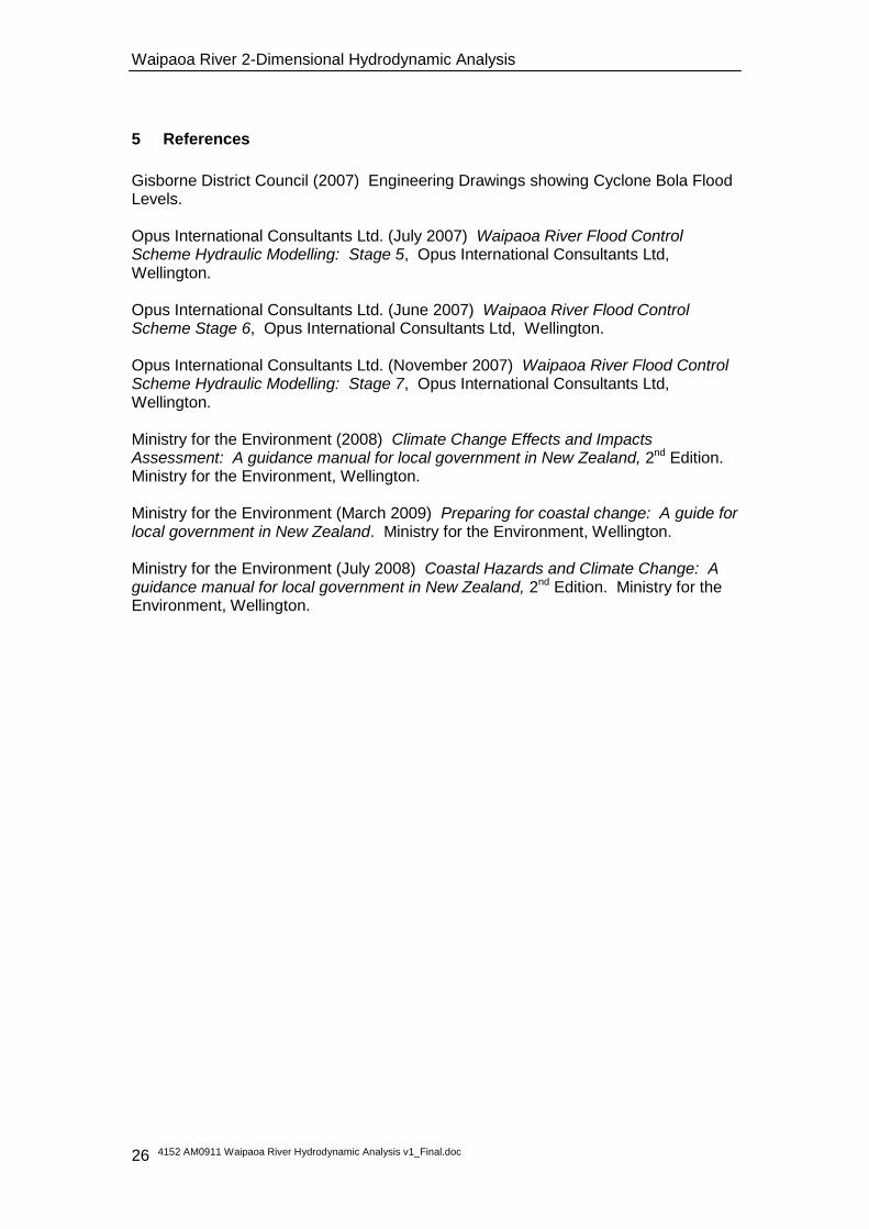
5 References
Gisborne District Council (2007) Engineering Drawings showing Cyclone Bola Flood Levels. Opus International Consultants Ltd. (July 2007) Waipaoa River Flood Control Scheme Hydraulic Modelling: Stage 5, Opus International Consultants Ltd, Wellington. Opus International Consultants Ltd. (June 2007) Waipaoa River Flood Control Scheme Stage 6, Opus International Consultants Ltd, Wellington. Opus International Consultants Ltd. (November 2007) Waipaoa River Flood Control Scheme Hydraulic Modelling: Stage 7, Opus International Consultants Ltd, Wellington. Ministry for the Environment (2008) Climate Change Effects and Impacts Assessment: A guidance manual for local government in New Zealand, 2nd Edition. Ministry for the Environment, Wellington. Ministry for the Environment (March 2009) Preparing for coastal change: A guide for local government in New Zealand. Ministry for the Environment, Wellington. Ministry for the Environment (July 2008) Coastal Hazards and Climate Change: A guidance manual for local government in New Zealand, 2nd Edition. Ministry for the Environment, Wellington.

Waipaoa River 2-Dimensional Hydrodynamic Analysis
4152 AM0911 Waipaoa River Hydrodynamic Analysis v1_Final.doc 27
6 Appendix 1: Simulation Files
Simulation Files from Mike21 2DModel runs:

Waipaoa River 2-Dimensional Hydrodynamic Analysis
4152 AM0911 Waipaoa River Hydrodynamic Analysis v1_Final.doc 28
7 Appendix 2: Plans/Profiles
There are 7 A1 size plans/profiles included with this report. An image of each is included below.

Waipaoa River 2-Dimensional Hydrodynamic Analysis
4152 AM0911 Waipaoa River Hydrodynamic Analysis v1_Final.doc 29

Waipaoa River 2-Dimensional Hydrodynamic Analysis
4152 AM0911 Waipaoa River Hydrodynamic Analysis v1_Final.doc 30

Waipaoa River 2-Dimensional Hydrodynamic Analysis
4152 AM0911 Waipaoa River Hydrodynamic Analysis v1_Final.doc 31

Waipaoa River 2-Dimensional Hydrodynamic Analysis
4152 AM0911 Waipaoa River Hydrodynamic Analysis v1_Final.doc 32