WAFER TYPE PROCESS VALVE T 211-C
4
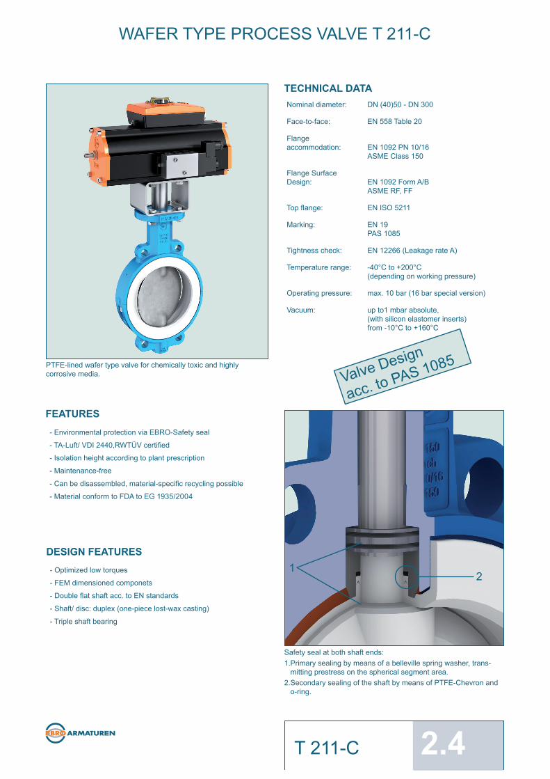
2.4 T 211-C 1 2 WAFER TYPE PROCESS VALVE T 211-C PTFE-lined wafer type valve for chemically toxic and highly corrosive media. Safety seal at both shaft ends: 1.Primary sealing by means of a belleville spring washer, trans- mitting prestress on the spherical segment area. 2.Secondary sealing of the shaft by means of PTFE-Chevron and o-ring. TECHNICAL DATA Nominal diameter: DN (40)50 - DN 300 Face-to-face: EN 558 Table 20 Flange accommodation: EN 1092 PN 10/16 ASME Class 150 Flange Surface Design: EN 1092 Form A/B ASME RF, FF Top flange: EN ISO 5211 Marking: EN 19 PAS 1085 Tightness check: EN 12266 (Leakage rate A) Temperature range: -40°C to +200°C (depending on working pressure) Operating pressure: max. 10 bar (16 bar special version) Vacuum: up to1 mbar absolute, (with silicon elastomer inserts) from -10°C to +160°C FEATURES - Environmental protection via EBRO-Safety seal - TA-Luft/ VDI 2440,RWTÜV certified - Isolation height according to plant prescription - Maintenance-free - Can be disassembled, material-specific recycling possible - Material conform to FDA to EG 1935/2004 DESIGN FEATURES - Optimized low torques - FEM dimensioned componets - Double flat shaft acc. to EN standards - Shaft/ disc: duplex (one-piece lost-wax casting) - Triple shaft bearing Valve Design acc. to PAS 1085
Transcript of WAFER TYPE PROCESS VALVE T 211-C
2.4T [email protected]
10.2020
12
18
0
2
4
6
8
10
12
14
16
-40 180160140120100806040200-20 200
WAFER TYPE PROCESS VALVE T 211-C WAFER TYPE PROCESS VALVE T 211-C
TORQUE
Kv-VALUES
Subject to change without notice
- The Kv-value [m³ per hour] is the fl ow of water at a temperature of 5°C to 30°C (41°F to 86°F) at ∆p of 1 bar
- The Kv-values specifi ed are based on tests carried out by the Delfter Hydraulics Laboratories, the Netherlands
- Permissible velocity of fl ow Vmax 4,5 m/s for liquids, Vmax 70 m/s for gases
- The throttle function is linear at an angle 30° to 70°
- Avoid cavitation
For further values, please contact our engineers.
- The torque values specifi ed (Md) are based on dry media and are measured with air at a temperature of 20 °C
- The values specifi ed are based on the initial breakaway torque (disc disengages from seat, torque then drops)
- Dynamic torque specifi cation available upon request
Regarding the dimensioning of actuators, please contact our engineers.
PRESSURE/TEMPERA-TURE DIAGRAM
PTFE-lined wafer type valve for chemically toxic and highly corrosive media.
Safety seal at both shaft ends:1.Primary sealing by means of a belleville spring washer, trans- mitting prestress on the spherical segment area.2.Secondary sealing of the shaft by means of PTFE-Chevron and o-ring.
TECHNICAL DATANominal diameter: DN (40)50 - DN 300
Face-to-face: EN 558 Table 20
Flange accommodation: EN 1092 PN 10/16
ASME Class 150
Flange Surface Design: EN 1092 Form A/B
ASME RF, FF
Top fl ange: EN ISO 5211
Marking: EN 19PAS 1085
Tightness check: EN 12266 (Leakage rate A)
Temperature range: -40°C to +200°C(depending on working pressure)
Operating pressure: max. 10 bar (16 bar special version)
Vacuum: up to1 mbar absolute,(with silicon elastomer inserts)from -10°C to +160°C
FEATURES- Environmental protection via EBRO-Safety seal
- TA-Luft/ VDI 2440,RWTÜV certifi ed
- Isolation height according to plant prescription
- Maintenance-free
- Can be disassembled, material-specifi c recycling possible
- Material conform to FDA to EG 1935/2004
DESIGN FEATURES- Optimized low torques
- FEM dimensioned componets
- Double fl at shaft acc. to EN standards
- Shaft/ disc: duplex (one-piece lost-wax casting)
- Triple shaft bearing
Valve Design
acc. to PAS 1085
DN (mm) 40/50 65 80 100 150 200 250 300Size (in) 1½ 2 2½ 3 4 6 8 10 12MD (Nm) 35 35 55 70 135 170 320 380
MAST (Nm)* 105 105 250 250 480 480 1020 1020*Maximum torques (Nm)
Pressure-Temperature-Diagram for valves with silicone elastomer inserts
Service limitation with Fluor carbon inserts (FPM) from -10°C up to +120°C
Service limitation with EPDM elatomer inserts from -10°C up to +180°C
Vacuum service to 1mbar absolute, from -10°C up to +160°C. Valve installation between fl anges
DN 50 - 150, special design
DN 50 - 300
System Temperature TS (°C)
Sys
tem
Pre
ssur
e P
S (b
ar)
DN[mm]
Size[in]
Opening angle α°20° 30° 40° 50° 60° 70° 80° 90°
1) Kv-values metal disc40/50 1½ 2 4 5 16 35 57 81 101 114
65 2½ 5 8 25 56 99 153 216 28780 3 13 12 30 69 131 216 328 467100 4 13 25 61 121 207 319 459 627150 6 50 94 171 303 509 810 1226 1778200 8 137 149 344 696 1178 1764 2426 3137250 10 178 291 562 1021 1699 2626 3832 5348300 12 395 378 820 1638 2751 4079 5538 7049
2) Kv-values PFA-disc40/50 1½ 2 2 4 13 25 40 53 63 66
65 2½ 3 9 26 48 74 98 117 12680 3 4 14 38 71 108 143 171 186100 4 6 16 48 95 151 209 262 303150 6 18 60 161 317 526 787 1096 1452200 8 125 176 395 756 1234 1807 2449 3136250 10 138 333 644 1103 1744 2599 3702 5086300 12 203 462 872 1479 2329 3471 4950 6814

WAFER TYPE PROCESS VALVE T 211-C
MATERIAL SPECIFICATION AND PARTS LIST
Subject to change without notice
Subject to change without notice
WAFER TYPE PROCESS VALVE T 211-C
** recommended spare parts
Dimensions [mm]DN
[mm]Size[in] A B C ØD ØDi E Flange ØF G h1 H2 Z Weight
[kg]40/50 1½ 2 126 95 221 112 49 43 F07 90 11 3 22 25 3,5
65 2½ 150 103 253 120 61 46 F07 90 11 3 22 41 480 3 157 124 281 138 80 46 F07 90 14 3 26 66 6100 4 180 135 315 160 100 52 F07 90 14 3 26 85 8150 6 210 167 377 215 151 56 F10 125 17 3 31 141 11200 8 240 190 430 269 196 60 F12 150 17 3 31 187 18250 10 275 232 507 324 248 68 F12 150 22 3 40,5 239 32300 12 298 260 558 374 293 78 F14 175 22 4 41,5 283 46
T 211-C with bare shaft end acc. to EN ISO 5211
Pos. Description Material Material-No. ASTM Pos. Description Material Material-No. ASTM
1 Body 11** Disc/Shaft (one-piece type)
Nodular Cast Iron EN-JS 1049 EN 1563 A395 St. Steel/St. Steel X2CrNiMo22-5-3/ 1.4469/ Duplex
2** Seat X2CrNiMo22-5-3 1.4469
PTFE Polytetrafluorethylene PTFE St.Steel/PFA coated X2CrNiMo22-5-3/ 1.4469/ Duplex/
M.-PTFE Polytetrafluorethylene modified X2CrNiMo22-5-3/ Perfluoralkoxy
Cond.-PTFE Polytetrafluorethylene conductive St. Steel/PFA conductive X2CrNiMo22-5-3/ 1.4469/ Duplex/
3** Elastomer insert X2CrNiMo22-5-3/ Perfluoralkoxy
Silicon Silicon - rubber MVQ VMQ 11.1 Lower shaft (DN 40/50 only)
4 DU-bearing Stainless Steel X2CrNiMoN22-5-3 1.4469 Duplex
Steel / PTFE coated 12 Lower shaft stup (DN 65 - DN 200 only)
5** Trust collar Stainless Steel X39CrMo 17-1 1.4122
Stainless Steel X5CrNiMo17-12-2 1.4401 316 13 Wiper ring
6 Belleville spring washer PTFE Polytetrafluorethylene PTFE PTFE
Stainless Steel X12CrNi177 1.4568 631 14 Screw
7** O-Ring Stainless Steel A4-70
FPM Fluorocarbon rubber FPM FKM 15** Thrust ring
8** Chevron seal PTFE Polytetrafluorethylene PTFE PTFE
PTFE Polytetrafluorethylene PTFE PTFE 16** O-Ring
9 Groove pin FPM Fluorocarbon rubber FKM
Stainless Steel A2 17 Spiral spring
10 Type plate Spring steel X10CrNi 18-8 1.4310 301
Stainless Steel 18 Buttstrap
19 Screw
Above-mentioned materials of the basic version, other materials upon request Stainless Steel A2-70
Wafer type process valve T 211-C

WAFER TYPE PROCESS VALVE T 211-C
MATERIAL SPECIFICATION AND PARTS LIST
Subject to change without notice
Subject to change without notice
WAFER TYPE PROCESS VALVE T 211-C
** recommended spare parts
Dimensions [mm]DN
[mm]Size[in] A B C ØD ØDi E Flange ØF G h1 H2 Z Weight
[kg]40/50 1½ 2 126 95 221 112 49 43 F07 90 11 3 22 25 3,5
65 2½ 150 103 253 120 61 46 F07 90 11 3 22 41 480 3 157 124 281 138 80 46 F07 90 14 3 26 66 6100 4 180 135 315 160 100 52 F07 90 14 3 26 85 8150 6 210 167 377 215 151 56 F10 125 17 3 31 141 11200 8 240 190 430 269 196 60 F12 150 17 3 31 187 18250 10 275 232 507 324 248 68 F12 150 22 3 40,5 239 32300 12 298 260 558 374 293 78 F14 175 22 4 41,5 283 46
T 211-C with bare shaft end acc. to EN ISO 5211
Pos. Description Material Material-No. ASTM Pos. Description Material Material-No. ASTM
1 Body 11** Disc/Shaft (one-piece type)
Nodular Cast Iron EN-JS 1049 EN 1563 A395 St. Steel/St. Steel X2CrNiMo22-5-3/ 1.4469/ Duplex
2** Seat X2CrNiMo22-5-3 1.4469
PTFE Polytetrafluorethylene PTFE St.Steel/PFA coated X2CrNiMo22-5-3/ 1.4469/ Duplex/
M.-PTFE Polytetrafluorethylene modified X2CrNiMo22-5-3/ Perfluoralkoxy
Cond.-PTFE Polytetrafluorethylene conductive St. Steel/PFA conductive X2CrNiMo22-5-3/ 1.4469/ Duplex/
3** Elastomer insert X2CrNiMo22-5-3/ Perfluoralkoxy
Silicon Silicon - rubber MVQ VMQ 11.1 Lower shaft (DN 40/50 only)
4 DU-bearing Stainless Steel X2CrNiMoN22-5-3 1.4469 Duplex
Steel / PTFE coated 12 Lower shaft stup (DN 65 - DN 200 only)
5** Trust collar Stainless Steel X39CrMo 17-1 1.4122
Stainless Steel X5CrNiMo17-12-2 1.4401 316 13 Wiper ring
6 Belleville spring washer PTFE Polytetrafluorethylene PTFE PTFE
Stainless Steel X12CrNi177 1.4568 631 14 Screw
7** O-Ring Stainless Steel A4-70
FPM Fluorocarbon rubber FPM FKM 15** Thrust ring
8** Chevron seal PTFE Polytetrafluorethylene PTFE PTFE
PTFE Polytetrafluorethylene PTFE PTFE 16** O-Ring
9 Groove pin FPM Fluorocarbon rubber FKM
Stainless Steel A2 17 Spiral spring
10 Type plate Spring steel X10CrNi 18-8 1.4310 301
Stainless Steel 18 Buttstrap
19 Screw
Above-mentioned materials of the basic version, other materials upon request Stainless Steel A2-70
Wafer type process valve T 211-C

2.4T [email protected]
10.2020
12
18
0
2
4
6
8
10
12
14
16
-40 180160140120100806040200-20 200
WAFER TYPE PROCESS VALVE T 211-C WAFER TYPE PROCESS VALVE T 211-C
TORQUE
Kv-VALUES
Subject to change without notice
- The Kv-value [m³ per hour] is the fl ow of water at a temperature of 5°C to 30°C (41°F to 86°F) at ∆p of 1 bar
- The Kv-values specifi ed are based on tests carried out by the Delfter Hydraulics Laboratories, the Netherlands
- Permissible velocity of fl ow Vmax 4,5 m/s for liquids, Vmax 70 m/s for gases
- The throttle function is linear at an angle 30° to 70°
- Avoid cavitation
For further values, please contact our engineers.
- The torque values specifi ed (Md) are based on dry media and are measured with air at a temperature of 20 °C
- The values specifi ed are based on the initial breakaway torque (disc disengages from seat, torque then drops)
- Dynamic torque specifi cation available upon request
Regarding the dimensioning of actuators, please contact our engineers.
PRESSURE/TEMPERA-TURE DIAGRAM
PTFE-lined wafer type valve for chemically toxic and highly corrosive media.
Safety seal at both shaft ends:1.Primary sealing by means of a belleville spring washer, trans- mitting prestress on the spherical segment area.2.Secondary sealing of the shaft by means of PTFE-Chevron and o-ring.
TECHNICAL DATANominal diameter: DN (40)50 - DN 300
Face-to-face: EN 558 Table 20
Flange accommodation: EN 1092 PN 10/16
ASME Class 150
Flange Surface Design: EN 1092 Form A/B
ASME RF, FF
Top fl ange: EN ISO 5211
Marking: EN 19PAS 1085
Tightness check: EN 12266 (Leakage rate A)
Temperature range: -40°C to +200°C(depending on working pressure)
Operating pressure: max. 10 bar (16 bar special version)
Vacuum: up to1 mbar absolute,(with silicon elastomer inserts)from -10°C to +160°C
FEATURES- Environmental protection via EBRO-Safety seal
- TA-Luft/ VDI 2440,RWTÜV certifi ed
- Isolation height according to plant prescription
- Maintenance-free
- Can be disassembled, material-specifi c recycling possible
- Material conform to FDA to EG 1935/2004
DESIGN FEATURES- Optimized low torques
- FEM dimensioned componets
- Double fl at shaft acc. to EN standards
- Shaft/ disc: duplex (one-piece lost-wax casting)
- Triple shaft bearing
Valve Design
acc. to PAS 1085
DN (mm) 40/50 65 80 100 150 200 250 300Size (in) 1½ 2 2½ 3 4 6 8 10 12MD (Nm) 35 35 55 70 135 170 320 380
MAST (Nm)* 105 105 250 250 480 480 1020 1020*Maximum torques (Nm)
Pressure-Temperature-Diagram for valves with silicone elastomer inserts
Service limitation with Fluor carbon inserts (FPM) from -10°C up to +120°C
Service limitation with EPDM elatomer inserts from -10°C up to +180°C
Vacuum service to 1mbar absolute, from -10°C up to +160°C. Valve installation between fl anges
DN 50 - 150, special design
DN 50 - 300
System Temperature TS (°C)
Sys
tem
Pre
ssur
e P
S (b
ar)
DN[mm]
Size[in]
Opening angle α°20° 30° 40° 50° 60° 70° 80° 90°
1) Kv-values metal disc40/50 1½ 2 4 5 16 35 57 81 101 114
65 2½ 5 8 25 56 99 153 216 28780 3 13 12 30 69 131 216 328 467100 4 13 25 61 121 207 319 459 627150 6 50 94 171 303 509 810 1226 1778200 8 137 149 344 696 1178 1764 2426 3137250 10 178 291 562 1021 1699 2626 3832 5348300 12 395 378 820 1638 2751 4079 5538 7049
2) Kv-values PFA-disc40/50 1½ 2 2 4 13 25 40 53 63 66
65 2½ 3 9 26 48 74 98 117 12680 3 4 14 38 71 108 143 171 186100 4 6 16 48 95 151 209 262 303150 6 18 60 161 317 526 787 1096 1452200 8 125 176 395 756 1234 1807 2449 3136250 10 138 333 644 1103 1744 2599 3702 5086300 12 203 462 872 1479 2329 3471 4950 6814


![Section 18 Butterfly Valves - AAP Industries · BUTTERFLY VALVES [18] Wafer Butterfly Valve with Gear-Op Stainless Steel Wafer Butterfly Valve Wafer Butterfly Valve with Stainless](https://static.fdocuments.us/doc/165x107/60a1925cd0b68c353a5fc104/section-18-butterfly-valves-aap-industries-butterfly-valves-18-wafer-butterfly.jpg)