
VZ Alloytec Manifold Insulators Fitting Instructions ... · MACE ENGINENEERING GROUP VZ Alloytec...
22
MACE ENGINENEERING GROUP VZ Alloytec Manifold Insulators Fitting Instructions (Installed on a 3.6L Alloytec VZ) For additional information on this product and all other products please visit our support website; http://support.maceengineering.com.au/Knowledgebase/List The following instructions illustrate the installation of a 12mm manifold insulator kit on a VZ SV6 Alloytec. However the installation process is the same for all models in the VZ range including the 25MM manifold Insulator.
-
Upload
truongdung -
Category
Documents
-
view
229 -
download
0
Transcript of VZ Alloytec Manifold Insulators Fitting Instructions ... · MACE ENGINENEERING GROUP VZ Alloytec...

MACE ENGINENEERING GROUP
VZ Alloytec Manifold Insulators
Fitting Instructions (Installed on a 3.6L Alloytec VZ)
For additional information on this product and all other products please visit our support website;
http://support.maceengineering.com.au/Knowledgebase/List
The following instructions illustrate the installation of a 12mm manifold insulator kit on a VZ SV6 Alloytec. However the installation
process is the same for all models in the VZ range including the 25MM manifold Insulator.

MACE ENGINENEERING GROUP
Tools
Flat-Head Screwdriver
4mm Socket
Flathead Pliers
10mm Socket
13mm Socket and Spanner
VZ Alloytec Executive (Grey Manifold)

MACE ENGINENEERING GROUP
PART 1: REMOVING MANIFOLD
Step 1: There are 5 clips that fasten the radiator cover. Use a flat screwdriver to lift them up, then remove them by hand.
The radiator cover can now be removed exposing the radiator.

MACE ENGINENEERING GROUP
Step 2: Loosen the hose clamp on the inlet duct at the front of the throttle body using a socket or spanner. Loosen the hose clamp on the inlet duct near the air box using a socket or spanner. The hose clamps should be loosened enough to allow for the hose sections to easily come off their connections.
Step 3: Locate the plastic duct that is inside the rubber tube as shown below

MACE ENGINENEERING GROUP
Using a flathead screwdriver separate the plastic duct from the hose connection.
Loosen the inlet duct near the airbox.

MACE ENGINENEERING GROUP
Step 4: Pull on the assembly as shown and the entire inlet duct should come out.
The image below shows the front of the engine with the inlet duct removed.

MACE ENGINENEERING GROUP
Step 5: Remove the two clips holding each half of the engine cover (not seen) & remove the covers.
Step 6: Separate the hose from the inlet manifold duct using a flathead screwdriver.

MACE ENGINENEERING GROUP
Now that the hose has been loosened from the duct, the hose can be completely removed from the duct by pulling the hose off the duct.
Step 7: Remove the electrical wiring clip at the location shown.

MACE ENGINENEERING GROUP
Such clips are removed by gently lifting the tab on top & pulling the electrical wiring clip.
Step 8: Next disconnect the vacuum hose from its connection which is located next to the electrical wiring clip. The vacuum hose can be disconnected by simply pulling the hose off its connection.

MACE ENGINENEERING GROUP
Step 9: On the other side of the inlet manifold there is an identical hose as illustrated in step 6. Remove this hose using the exact same process outlined in step 6.
Step 10: Below the hose connected to the inlet manifold, there is another hose fastened to a clip. Free the hose from its clip as illustrated below.

MACE ENGINENEERING GROUP
Step 11: Remove the second electrical clip in the position shown in the same manner as the electrical clip described in step 7.
Step 12: Loosen & remove the bolt in the following position using a socket or spanner.

MACE ENGINENEERING GROUP
Step 13: Remove the hose connecting the break booster to the inlet manifold from the break booster end which is located in the following position.
Turn the handles of the clip towards you. Clamp the handles of the clip and drag the clip away from the connection as illustrated below.

MACE ENGINENEERING GROUP
The hose can now be pulled off its connection from the break booster end rather than the manifold end as it is easier to remove.
Step 14: Using a socket, loosen & remove the 6 bolts that fasten the manifold to the engine. To remove the back bolt the cowl can be removed for easier access. Do not try and remove the bolts located in the hollow sections as it is not necessary.

MACE ENGINENEERING GROUP
Step 15: Disconnect the small hose near the throttle body by pulling the hose off the inlet manifold connection.
Step 16: Disconnect the electrical clip located below the throttle body. This firstly involves releasing the yellow pin by pulling the pin out. The electrical clip can then be disconnected by pulling the electrical clip off its connection.

MACE ENGINENEERING GROUP
Step 17: Snip the cable tie in the position shown.
Step 18: The entire manifold can be removed exposing the runners as shown below:
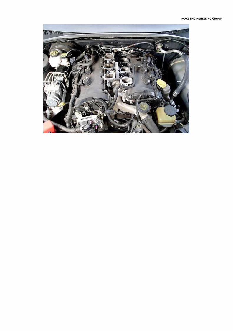
MACE ENGINENEERING GROUP

MACE ENGINENEERING GROUP
PART 2: INSTALLING MANIFOLD INSULATOR
Step 1: Remove the gaskets from the underside of the manifold ports.
Step 2: Scrape off any remaining gasket remains using a blade and clean the surface of the runners with a rag & solvent such as Prepsolv. Also scrape and clean the surface of the inlet manifold runners with a rag and solvent if required.

MACE ENGINENEERING GROUP
Step 3: Spread the gasket sealant provided with the kit around the surface of each runner. Do not spread gasket sealant around the bolt holes. Also spread gasket sealant on the top surface of each manifold insulator. It is also equally important for the surface of each insulator facing the inlet manifold to have a layer of gasket sealant so that the inlet manifold is appropriately sealed to avoid any air leakage.
(Picture is to be used as a guide to illustrate how to spread the Silicone over the Manifold Insulator)

MACE ENGINENEERING GROUP
Step 4: Align the manifold insulators provided with the runner surfaces. Make sure the insulators are inserted onto the surface correctly by aligning the insulators with the bolt holes. Push them into place so that the gasket
sealant firmly holds the manifold insulators to the runner surfaces.

MACE ENGINENEERING GROUP
Step 5: Place the inlet manifold onto the manifold insulators. (*** NOTE – EXERCISE EXTREME CAUTION TO ENSURE NOTHING FALLS INSIDE THE RUNNERS. IF ANYTHING DOES FALL IN, IT MUST BE REMOVED OTHERWISE DAMAGE TO THE ENGINE WILL RESULT). To align the inlet manifold correctly with the manifold insulators, place the new bolts given with the kit into the inlet manifold bolt holes. When the inlet manifold is placed onto the manifold insulators the bolts will align with the bolt holes. Make sure a spring washer is firstly added onto each bolt followed by a washer to properly tighten the bolts.
Remember to use the longer bolts supplied with the Insulator Kit.
Make sure that the bolts provided with the kit are matched up to the standard bolts that were used so that the longer and shorter bolts are used in the correct bolt holes of the inlet manifold.

MACE ENGINENEERING GROUP
Step 6: The bolts now need to be tightened. Tighten the bolts slightly starting with the bottom right bolt, top left, top right then the middle bolts. This ensures that the inlet manifold is pressed onto the manifold insulators in an evenly distributed manner. The bolts can now be tightened to their maximum capacity in the same order outlined. Remember to use the longer bolts supplied with the 25MM & 12MM manifold insulator kit.
(Note this picture shows the engine bay of a VE MY09.5 Alloytec. However the process is still applicable)
MACE ENGINENEERING GROUP
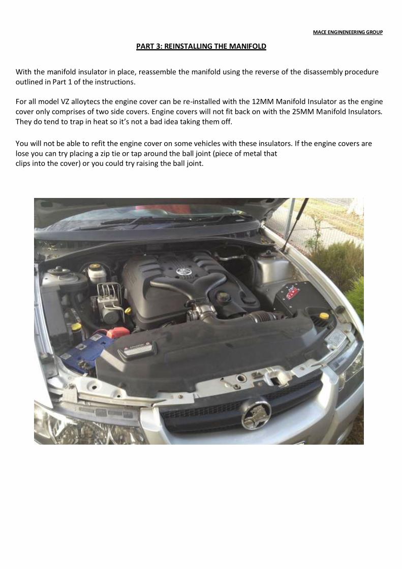
PART 3: REINSTALLING THE MANIFOLD With the manifold insulator in place, reassemble the manifold using the reverse of the disassembly procedure outlined in Part 1 of the instructions. For all model VZ alloytecs the engine cover can be re-installed with the 12MM Manifold Insulator as the engine cover only comprises of two side covers. Engine covers will not fit back on with the 25MM Manifold Insulators. They do tend to trap in heat so it’s not a bad idea taking them off.
You will not be able to refit the engine cover on some vehicles with these insulators. If the engine covers are lose you can try placing a zip tie or tap around the ball joint (piece of metal that clips into the cover) or you could try raising the ball joint.