VXI: THE TEST PLATFORM OF THE FUTURE? - Positioned for the Future.pdfVXI: THE TEST PLATFORM OF THE...
12
VXI: THE TEST PLATFORM OF THE FUTURE? Charles Greenberg EADS North America Defense Test & Services 4 Goodyear St. Irvine, CA 92618 (949) 859-8999 [email protected] Abstract - As VME Extensions for Instrumentation (VXI) turns 20 years old, its relevance for new applications is tested in the presence of the alternatives. This paper looks at the past successes and failures of the VXI platform, and then looks at present and future applications with respect to how well the standard holds up. Finally, this paper examines recent VME enhancements, including VITA-41, also known as VXS, to extend the applicability of the VXI platform, looking forward to the next twenty years. INTRODUCTION As part of the research for this paper, I visited with Robert (Wade) Lowdermilk and Anthony Estrada of BAE Systems in San Diego, California. Their company uses VXI extensively to build Synthetic Instruments (SI) and test systems, so they seemed like natural people to talk with about the future of the VXI bus. When I informed them of the proposed title of this paper: VXI: The Test Platform of the Future, Wade laughed and quipped that he did not think that it would win the “Best Paper” award. Wade explained that the BAE Systems strategy was to replace their VXI instruments, one by one, with PXI instruments in PXI-VXI carriers, as suitable PXI instruments became available. Eventually, when all of the instruments in the system were in the PXI format, they would switch over to a PXI chassis altogether. Needless to say, the BAE Systems meeting that day cured me of any thoughts that I had of this paper being a simple task. Was the nearly 20 year old VXI platform, even including its recent VME64 speed enhancement, going to be replaced with a newer architecture like PXI or LXI? To answer this question, we will need to observe the successes and failures of the VXI platform, compare it to some of the newer platforms, and, if the VXI platform has a few deficits but is otherwise found to still be relevant, suggest any changes necessary to make VXI the premier modular test platform for another 20 years or more. SUCCESSES AND FAILURES OF VXI The story of VXI began in the mid-1980’s just as the first U.S. Navy CASS systems were being designed using VME instruments built in a special form factor that was similar to that of the yet-to- be-defined C-sized VXI module. In 1987, the VXIbus Consortium, consisting of a group of interested companies including HP (now Agilent), Tektronix, Racal Instruments (now EADS North America Defense Test & Services), Colorado Data Systems, and Wavetek (now Fluke), was created to fill the need for an open industry standard. The standard was created to meet the consortium’s stated goals as listed below in Table 1: Table 1: Goals of VXI [1] Goal # Goal Description 1 Capability of handling demanding electronic test problems 2 Open standard to all designers/ manufacturers 3 Interoperability with modules that would work together seamlessly 4 Ability to reduce the size of current instrumentation 5 Ability to increase the speed of Automatic Test Equipment (ATE) systems 6 Cost-effective ATE solution In the 19 years since the creation of VXI, the achievement of these goals is apparent for the 1-4244-0052-X/06/$20.00 ©2006 IEEE 664
Transcript of VXI: THE TEST PLATFORM OF THE FUTURE? - Positioned for the Future.pdfVXI: THE TEST PLATFORM OF THE...

VXI: THE TEST PLATFORM OF THE FUTURE?
Charles Greenberg EADS North America Defense Test & Services
4 Goodyear St. Irvine, CA 92618 (949) 859-8999
Abstract - As VME Extensions for Instrumentation (VXI) turns 20 years old, its relevance for new applications is tested in the presence of the alternatives. This paper looks at the past successes and failures of the VXI platform, and then looks at present and future applications with respect to how well the standard holds up. Finally, this paper examines recent VME enhancements, including VITA-41, also known as VXS, to extend the applicability of the VXI platform, looking forward to the next twenty years.
INTRODUCTION
As part of the research for this paper, I visited with Robert (Wade) Lowdermilk and Anthony Estrada of BAE Systems in San Diego, California. Their company uses VXI extensively to build Synthetic Instruments (SI) and test systems, so they seemed like natural people to talk with about the future of the VXI bus. When I informed them of the proposed title of this paper: VXI: The Test Platform of the Future, Wade laughed and quipped that he did not think that it would win the “Best Paper” award.
Wade explained that the BAE Systems strategy was to replace their VXI instruments, one by one, with PXI instruments in PXI-VXI carriers, as suitable PXI instruments became available. Eventually, when all of the instruments in the system were in the PXI format, they would switch over to a PXI chassis altogether.
Needless to say, the BAE Systems meeting that day cured me of any thoughts that I had of this paper being a simple task. Was the nearly 20 year old VXI platform, even including its recent VME64 speed enhancement, going to be replaced with a
newer architecture like PXI or LXI? To answer this question, we will need to observe the successes and failures of the VXI platform, compare it to some of the newer platforms, and, if the VXI platform has a few deficits but is otherwise found to still be relevant, suggest any changes necessary to make VXI the premier modular test platform for another 20 years or more.
SUCCESSES AND FAILURES OF VXI
The story of VXI began in the mid-1980’s just as the first U.S. Navy CASS systems were being designed using VME instruments built in a special form factor that was similar to that of the yet-to-be-defined C-sized VXI module. In 1987, the VXIbus Consortium, consisting of a group of interested companies including HP (now Agilent), Tektronix, Racal Instruments (now EADS North America Defense Test & Services), Colorado Data Systems, and Wavetek (now Fluke), was created to fill the need for an open industry standard. The standard was created to meet the consortium’s stated goals as listed below in Table 1:
Table 1: Goals of VXI [1]
Goal # Goal Description 1 Capability of handling demanding electronic
test problems 2 Open standard to all designers/
manufacturers3 Interoperability with modules that would work
together seamlessly 4 Ability to reduce the size of current
instrumentation 5 Ability to increase the speed of Automatic
Test Equipment (ATE) systems 6 Cost-effective ATE solution
In the 19 years since the creation of VXI, the achievement of these goals is apparent for the
1-4244-0052-X/06/$20.00 ©2006 IEEE 664
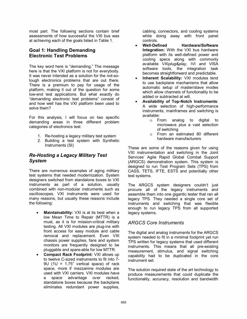
most part. The following sections contain brief assessments of how successful the VXI bus was at achieving each of the goals listed in Table 1.
Goal 1: Handling Demanding Electronic Test Problems
The key word here is “demanding.” The message here is that the VXI platform is not for everybody. It was never intended as a solution for the not-so-tough electronics problems that are out there. There is a premium to pay for usage of the platform, making it out of the question for some low-end test applications. But what exactly do “demanding electronic test problems” consist of and how well has the VXI platform been used to solve them?
For this analysis, I will focus on two specific demanding areas in three different problem categories of electronics test:
1. Re-hosting a legacy military test system 2. Building a test system with Synthetic
Instruments (SI)
Re-Hosting a Legacy Military Test System
There are numerous examples of aging military test systems that needed modernization. System designers switched from standalone boxes to VXI instruments as part of a solution, usually combined with non-modular instruments such as oscilloscopes. VXI instruments were used for many reasons, but usually these reasons include the following:
• Maintainability: VXI is at its best when a low Mean Time to Repair (MTTR) is a must, as it is for mission-critical military testing. All VXI modules are plug-ins with front access for easy module and cable removal and replacement. Even VXI chassis power supplies, fans and system monitors are frequently designed to be pluggable and spare-able for low MTTR.
• Compact Rack Footprint: VXI allows up to twelve C-sized instruments to fit into 7-9U (1U = 1.75” vertical space) of rack space, more if mezzanine modules are used with VXI carriers. VXI modules have a space advantage over racked, standalone boxes because the backplane eliminates redundant power supplies,
cabling, connectors, and cooling systems while doing away with front panel controls.
• Well-Defined Hardware/Software Integration: With the VXI bus hardware platform with its well-defined power and cooling specs along with commonly available VXIplug&play, IVI and VISA software tools, the integration task becomes straightforward and predictable.
• Inherent Scalability: VXI modules tend to use backplane mechanisms that allow automatic setup of master/slave modes which allow channels of functionality to be added or subtracted at will.
• Availability of Top-Notch Instruments:A wide selection of high-performance instruments, mainframes and switching is available:
o From analog to digital to microwave plus a vast selection of switching
o From an estimated 80 different hardware manufacturers
These are some of the reasons given for using VXI instrumentation and switching in the Joint Services’ Agile Rapid Global Combat Support (ARGCS) demonstration system. This system is designed to run Test Program Sets (TPS) from CASS, TETS, IFTE, ESTS and potentially other test systems.
The ARGCS system designers couldn’t just procure all of the legacy instruments and assemble them into one gigantic tester that ran all legacy TPS. They needed a single core set of instruments and switching that was flexible enough to run legacy TPS from all supported legacy systems.
ARGCS Core Instruments
The digital and analog instruments for the ARGCS system needed to fit in a minimal footprint yet run TPS written for legacy systems that used different instruments. This means that all pre-existing measurement, stimulus, and signal switching capability had to be duplicated in the core instrument set.
The solution required state of the art technology to produce measurements that could duplicate the functionality, accuracy, resolution and bandwidth
665

of the legacy systems. To achieve this, two principles were used:
• Extra Dynamic Range: There are too many legacy measurement ranges in existence to duplicate them all on a single instrument. This necessitates using different ranges, but ranges that had more resolution than the preceding systems had. Some examples of this are in the table below:
Table 2: Comparison of ARGCS Dynamic Ranges to Those of Previous Test Systems
Instrument Type Legacy Specs ARGCS Specs Waveform Generator
12-bit 125 MS/s
16-bit 200 MS/s
Digitizer 8-bit 1 GS/s
10-bit 2GS/s
Digital Multimeter +/- 1.2 Million counts +/- 24 Million counts
• Extensions to Commercial-Off-the- Shelf (COTS) Hardware: The 340 mm (13.386”) depth of the VXI module gave ARGCS hardware designers room to extend the performance of COTS hardware (Digital Multimeters, Digitizers, Waveform Generators, etc.) by adding missing functionality.
ARGCS Switching
The key to solving the ARGCS switching riddle was flexibility. In this case, the depth of the VXI modules proved extremely helpful in building a group of switches that could reconfigure themselves into different legacy configurations. The implementation of reconfigurable switching configurations requires extra switches and traces on the switch card, which is only possible when you have room for them. So much room is available that a triple 8x24 expandable 60 MHz matrix could be built (over 900 relays) and fit in a single VXI slot. No other fixed-depth modular system in existence would have the board depth, area, or volume required to implement this.
Building a Test System with SI
At a March, 2006 Synthetic Instruments Working Group (SIWG) meeting, BAE Systems gave a presentation about an SI system that they built using the VXI bus. This synthetic system consists of signal measurement devices including:
• Analog to Digital Converters (ADCs): Both high-speed and narrowband types
• RF Down-converters with Local Oscillator • An RF Power Meter • An LF Signal Conditioner
and signal generation devices as follows:
• Arbitrary Waveform Generator (3) • RF Synthesizer
Figure 1: BAE Systems Synthetic Instrument Measurement and Stimulus System (SIMSS)
The system also includes a synchronization card to synchronize the various components and a switching “hood” which routes signals between the instruments and the system’s front panel interface.
Figure 2: Front Panel Interface to the BAE Systems SIMSS
System designers recently replaced an older digitizer with a digitizer from Acqiris to improve the system performance of their SI. Although the digitizer was a 6U Compact PCI card, they were
cPCI HIGH-SPEEDA/D CONVERTER
ARBITRARYFUNCTION
GENERATOR
SYNC BOARD
RF SYNTHESIZER
VME NARROW BANDA/D CONVERTER
RF DOWN CONVERTER
#1RF DOWN
CONVERTER #2
LF SIGNAL CONDITIONER
LOCAL OSCILLATOR
SLOT ZERO CONTROLLER
POWERMETER
666

able to accommodate it in their VXI system using a carrier from C&H Technologies. Carriers such as this make technology that is currently unavailable in a native VXI instrument available. This is exactly the way the performance of SI was supposed to be improved by those that envisioned it. The data converters need the ability to be updated as the technology comes into existence, and the VXI platform is accommodating this need.
Goal 2: Open Standard
Though originally a single standard, the VXI hardware standard is now usually associated with two separate software standards: Virtual Instrument Software Architecture (VISA) and VXIplug&play, and sometimes with the Interchangeable Virtual Instrument (IVI) standard. VXIplug&play and IVI are both driver standards with the latter making it possible to interchange like instruments at the driver interface level. The VISA library is an intermediate software layer which allows drivers to communicate using a variety of hardware interfaces (VXI, GPIB, LAN, USB, etc.) without changing the software interface.
Figure 3: Interrelationship of VXI and Other Related Open Standards
Since the introduction of the VXI specification, over 400 manufacturers have been assigned VXI manufacturers ID codes, although the consortium claims instrument availability from 80 different vendors. While the consortium itself has 19 member companies, including six sponsor-level members, the VXI consortium does not require vendors to join the consortium, although it is recommended.
Goal 3: Seamless Interoperability
While it may be self-evident that VXI modules and software of different types and from different vendors coexist and operate seamlessly, it has also been shown that other device types can operate in a VXI chassis alongside native VXI devices. Some examples are PXI modules, M-Modules (mezzanine cards) and VME modules in carriers that adapt these modules to VXI.
Figure 4: M-Module Mezzanine Instruments Used to Replace a Wavetek 1396 Arb
In Figure 4 an example is shown of a legacy instrument replacement. Fluke recently discontinued one of their older VXI waveform generators. A replacement was built using a COTS waveform generator M-Module (Talon Instruments MA1801A) along with a COTS amplifier/attenuator M-Module (Racal Instruments M1709) that duplicated the legacy voltage ranges. A special command parser was also created to map native commands of the legacy unit to the VXIplug&play drivers of the M-Modules. The result was replacement of > 85% of legacy functionality.
Goal 4: Reduced Size
Test system platforms that replace rack-mounted boxes with modules in a VXI chassis tend to be smaller in size than those that do not. This fact has been driving size-reductions in mission-critical test systems for years. In addition, VXI made it possible to build test systems that fit in transit cases like the Third Echelon Test System (TETS) for the U.S. Marine Corps. and the ARGCS demonstration for the Joint Services.
667

Figure 5: Third Echelon Test System (TETS) in Both Stowed and Deployed Configurations
Figure 6: Typical Configuration of the Agile Rapid Combat Support (ARGCS) System [2]
Goal 5: Increased Speed of ATE
Before the invention of VXI, and really to this day, the most common communication bus alternative to VXI was the General Purpose Interface Bus (GPIB). GPIB is traditionally a 1MB/s interface, although an 8MB/s high speed version is available now. VXI version 3.0 theoretically can transmit data at 160 MB/s using the fast 2 Edge VME (2eVME) extensions.
All of this begs the question: “How fast does an automatic test system need to operate?” Most of the time measurements are made, the system waits for relays and measurement apertures to settle, processes that are often orders of magnitude slower than the speed of the measurement bus. Even so, there is no denying that the trend is for systems with more memory, faster sampling, more channels, and more resolution. All of these factors continually pressure bus interfaces until, someday, it is not fast
enough. The key is to start with plenty of headroom, and clearly VXI still has not been used to the full extent of its current limitations, although this is not always voluntary.
Indeed, VXI and GPIB instruments have both been designed to execute Standard Commands for Programmable Instrumentation (SCPI) instructions for many years. These ASCII instructions are not particularly fast. The more recent trend, at least for VXI instruments, is the utilization of so-called register-based interfaces which do not require software parsing of the SCPI. This makes the instruments much faster and an IVI software interface can now be used for interchangeability instead of SCPI, although the IVI structure might serve to reduce throughput.
For legacy compatibility, as with the legacy waveform generator replacement example shown in Figure 4, SCPI commands can be implemented even for purely register-based instruments. This provides high-speed operation as well as preservation of TPS investment. This is accomplished by intercepting these commands underneath the VISA software layer, parsing them, and translating them into the equivalent register based control sequence.
The bottom line is that trends that are taking shape now and that will continue to for the next twenty years indicate that 160 MB/s across the VXIbus will eventually become a limiting factor which will need to be addressed if VXI is to remain intact as a useful platform by its 40th birthday.
Goal 6: Cost Effective ATE
The cost of ownership of test systems is influenced by factors other than just the purchase price. VXI systems, though sometimes costing more to procure than the GPIB equivalent, can be more cost-effective for one or more of the following reasons:
• Space Savings • Increased Reliability • Increased Maintainability • Reduced Cost of Integration
State-of-the-art GPIB instruments sometimes have better specifications than state-of-the-art VXI instruments. For companies that sell GPIB instruments in high volumes, economics dictate
668

that one can afford to continually push traditional instruments to new specification limits.
That said, the product life-cycle for the average GPIB instrument is much shorter than that of its VXI brethren, an important consideration when designing an ATE for a military application which may have a service life of twenty years plus.
For example, a frequency counter can have 10 or 12 digits, instead of 9 like a typical VXI counter. But this does not necessarily mean that time or frequency measurements will be any more accurate with the higher resolution unit. This depends on things like the frequency reference used and the trigger error of the measurement.
Companies that design modular instruments know that cost savings can be achieved and time to market reduced when modules are built on a standardized platform. Problems like power, cooling and design of the test interface are solved once and do not need to be designed again. This frees up the designer to focus on the measurement or stimulus function or functions that are required. This can create value for users of the VXI platform that constantly need to cope with new and changing requirements.
VXI Compatibility Issues
An additional goal for the VXI platform is backward and forward compatibility of the platform itself. While the specification has incorporated some VME hardware enhancements and related software enhancements, there is good compatibility with new and old instruments and controllers, especially when the VISA software library is used.
This is an important issue because the VXI platform is used by the military. Military test stations tend to remain in use for 20-30 years. If the VISA-based VXI controller is replaced down the road, one would count on all of the instruments continuing to function with no software code modification. If a VISA-based instrument is replaced down the road, no bus compatibility problems will be had, although some work may be needed to keep legacy TPS running.
A “Report Card” for the VXI Platform
Table 3 below summarizes the performance of the VXI platform with respect to the goals that it was
expected to achieve. In addition, compatibility issues and power and cooling performance are rated since these are frequently critically important to VXI users trying to solve demanding test problems.
Table 3: VXI Goal Achievement Report Card
# Goal Description Grade
1 Handle demanding electronic test problems A
2 Open standard A3 Interoperability A4 Reduce Instrumentation Size A-
5 Ability to increase the speed of Automatic Test Equipment (ATE) systems B-
6 Cost-effective ATE solution C7 Backward/Forward Compatibility A 8 Power and Cooling B+
ALTERNATIVES TO VXI
Now that we’ve explored the strengths and weaknesses of VXI relative to it’s stated goals, we still will not know if VXI should and will have a future unless we:
1. Compare VXI to other platforms that are trying to solve many of the same problems to the goals previously listed
2. Compare the performance of other platforms relative to these goals, decide whether VXI still has a place
3. Decide whether VXI is OK as is, or if it needs to be extended to deal with future demands
The main modern alternatives to VXI are PXI (including PXI Express) and LXI. GPIB will not be considered because it is being phased out in favor of LXI and USB interfaces on box instruments (although we will see these ports for some time to come).
The PXI Alternative
In 1997, National Instruments, Inc. unveiled PCI Extensions for Instrumentation (PXI) to the world. Like VXI, PXI was an extension made to an existing bus standard, in this case, Compact PCI (cPCI). Unlike VXI, PXI was not the result of the work of an industry consortium, although an alliance of PXI vendors, the PXI Systems Alliance (PXISA), was formed quickly after the introduction of PXI to promote the platform.
669

Initially, PXI gained product momentum from a wellspring of cPCI products that were becoming available, along with PCI products morphed into the PXI form factor. As the standard gained steam, instrument and switch products began to target the PXI/cPCI form factor, multiplying the number of product choices that could be used to build test systems.
PXI is available in 3U and 6U card sizes, but National Instruments is much more focused on 3U, thus 3U seems to be catching on. The small size of the cards allows PXI products to be positioned as solutions for rack mount, portable, and bench top test applications.
Figure 7: Rack Mount, Portable, and Benchtop PXI Configurations
Although the initial thrust of PXI instruments was mostly data acquisition, more recently traditional analog, digital and RF test instruments and switching have been developed for PXI. In reality, though, the small geometry (height and depth) of the 3U PXI platform tends to limit application modules to the types of things that fit the platform. For example, high-density switching is limited to low-power, low-voltage reed relays. Sources tend to have lower output powers and voltages due to the lower PXI voltages. Precision instruments tend to be less stable due to less room on the PCB for implementation of precision techniques. For rack-
mount applications, expensive rack is wasted to mount cards that are only 140 mm deep. By comparison, VXI modules are 340 mm deep and optimize the use of rack depth better. In addition, PXI lacks a standardized measurement of cooling performance like VXI-8, making it difficult to compare the expected performances of PXI mainframe alternatives. These limitations make it more difficult to use PXI as a solution for the most demanding problems in electronic test.
PXI Express Enhancements
In 2005, PXI-5 was added by the PXISA to specify how PCI Express could be used in PXI systems. As the original PXI spec (PXI-1) was leveraged from cPCI, PXI Express was based on the cPCI Express spec which was also released in mid-2005, only two months before PXI Express. Because PXI Express does not accommodate an interface to a switched serial architecture and has a limited number of PCI Express channels or lanes, the throughput of PXI Express is limited to about 6 GB/s. In addition, it doesn’t seem possible to use this architecture as an FPGA/DSP processor mesh network when extra processing power is needed.
PXI Express does not have a great deal of backward compatibility with PXI. New PXI hybrid modules will not fit in legacy PXI-1 slots. Legacy PXI-1 cards won’t fit in new hybrid PXI Express slots, although cPCI cards with only the J1 connector will fit. Table 4 summarizes the backward and forward compatibility of PXI Express with the original PXI.
Table 4: PXI Express Compatibility Chart [3]
670

A Rating for PXI
In this rating scale, we are not comparing PXI to its own original goals; we are comparing it to the VXI platform’s goals. PXI was designed for portability, for bench top usage, etc. which does not make it optimized for everything that VXI is optimized for. Table 5 lists how well PXI rates on the VXI report card items, not to be a criticism of PXI, but to see how well it replaces VXI.
Here are some of the factors that influenced the rating of PXI versus the PXI goals:
• Not as Cost Effective as Expected:Modules tend to be expensive when mezzanine boards are required to shrink packaging as they are on some switching and instrument cards.
• Standard Not Truly Open: The PXISA uses the spec, but doesn’t define it.
• No Power and Cooling Integration Guidelines: Its not always easy to tell whether the selected modules can be adequately cooled and powered in a PXI chassis.
• Interoperability Can be Difficult: There is no guarantee when using PXI that modules from different manufacturers will work together.
Table 5: PXI Goal Achievement Rating
# Goal Description Grade
1 Handle demanding electronic test problems C-
2 Open standard D3 Interoperability C- 4 Reduce Instrumentation Size B-
5 Ability to increase the speed of Automatic Test Equipment (ATE) systems B
6 Cost-effective ATE solution B7 Backward/Forward Compatibility C 8 Power and Cooling C
The LXI Alternative
In 2004, Agilent and VXI Technology teamed to launch a consortium to promote LAN Extensions for Instrumentation (LXI). A very active LXI Consortium is promoting and defining this interface which is both a replacement for the GPIB interface and an extension and standardization of the Ethernet interface for instrumentation.
Figure 8: LXI Instrument Packaging Concept [4]
LXI Enhancements
LXI extends the Local Area Network for instrumentation. The main advantages over the basic LAN interface are:
• A standardized system of discovery for LXI instruments (VXI-11)
• A standard web page interface • A high-speed wired trigger bus • A LAN triggering scheme based on IEEE-
1588• Resource management • An IVI interface to LXI features • Mechanical conventions for standard half-
rack and full-rack width instruments (see Figure 8)
Some of these features, such as LAN discovery, resource management, web page interface, and 1588 LAN triggers are still evolving within the LXI working groups. Throughput over the Gigabit Ethernet LXI bus is theoretically 120 MB/s, but actual performance is reduced by a latency of 50-120 μs caused by the TCP/IP software stack [5], Latency can be reduced by using a special LAN card with hardware stack processing, but this solution is much more expensive. In addition, some of the interoperability issues with LXI are being improved. At least for the moment, we cannot be sure what backward and forward compatibility for LXI instruments with these features will be like down the road.
671
A Rating for LXI
In this rating, we are not comparing LXI to its own original goals, just to the goals of VXI to determine whether or not LXI is a replacement for VXI.
Table 6: LXI Goal Achievement Rating
# Goal Description Grade
1 Handle demanding electronic test problems A
2 Open standard A3 Interoperability B- 4 Reduce Instrumentation Size C-
5 Ability to increase the speed of Automatic Test Equipment (ATE) systems B-
6 Cost-effective ATE solution B+7 Backward/Forward Compatibility C- 8 Power and Cooling B
PROPOSED CHANGES TO VXI
Despite the many improvements in the world of test and measurement that the VXI platform has made possible, it may be time to upgrade the VXI platform. Indeed, the PXI and LXI standards are evolving to incorporate changes to their base standards. This will give these standards long, useful lives as they change with the times to meet new demands.
The VXI bus specification has been unchanged since 2004 when VME64 was incorporated, while its base specification, the VME bus standard, has evolved. We need to ask ourselves:
• What are the relevant VME enhancements that are of interest?
• Can these enhancements be useful for VXI to deal with our future objectives?
• Are there features from the PXI and LXI standards that would be useful for VXI to deal with future objectives?
Relevant VME Enhancements
Since the VME64 standard was incorporated into the VME bus world, several enhancements have been added to increase speed and power handling of the bus. The most important enhancements are:
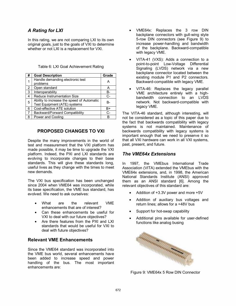
• VME64x: Replaces the 3 row DIN backplane connectors with gull-wing style 5-row DIN connectors (see Figure 9) to increase power-handling and bandwidth of the backplane. Backward-compatible with legacy VME.
• VITA-41 (VXS): Adds a connection to a point-to-point Low-Voltage Differential Signaling (LVDS) network via a new backplane connector located between the existing module P1 and P2 connectors. Backward-compatible with legacy VME.
• VITA-46: Replaces the legacy parallel VME architecture entirely with a high-bandwidth connection to an LVDS network. Not backward-compatible with legacy VME.
The VITA-46 standard, although interesting, will not be considered as a topic of this paper due to the fact that backwards compatibility with legacy systems is not maintained. Maintenance of backwards compatibility with legacy systems is important enough that we need to preserve it so that all VXI hardware can work in all VXI systems, past, present, and future.
The VME64x Extensions
In 1997, the VMEbus International Trade Association (VITA) extended the VMEbus with the VME64x extensions, and, in 1998, the American National Standards Institute (ANSI) approved them as an ANSI standard [6]. Among the relevant objectives of this standard are:
• Addition of +3.3V power and more +5V
• Addition of auxiliary bus voltages and return lines; allows for a +48V bus
• Support for hot-swap capability
• Additional pins available for user-defined functions like analog busing
Figure 9: VME64x 5 Row DIN Connector
672
The VME64x extension takes advantage of a new 5 row DIN connector that provides the extra contacts for the features listed above while maintaining compatibility with traditional 3 row backplane DIN connectors.
The VME64x extension would potentially be an important extension for the VXI platform because it adds +3.3V, which is useful for powering low-voltage digital circuitry. It also can add power distribution capability to other existing VXI rails when extra power is needed. The VME64x user-defined pins can be claimed by VXI for things like analog bus backplane connections, increased power to existing voltage rails, or daisy chained local buses.
The VITA41 (VXS) Extensions
In 2001, Motorola proposed VMEbus Switched Serial (VXS) extensions to the VMEbus and produced a draft spec (VITA 41.0) in 2002 [7]. The VXS extensions proposed a new high-density, differential P0 connector between the traditional VME P1 and P2 on the module. The new connector enables the module to be connected to a multi-gigabit serial bus network via up to two x4 bidirectional serial links.
Figure 10: VXS P0 Differential Serial Connector Shown with Keying Block Between P1 and P2
The VITA 41.0 specification calls out differential links routed via the backplane to the module slots and is “protocol agnostic” in that it does not specify the communication protocols that can be used to transfer data along the differential data paths. Instead, it relies on “dot specs” to describe VXS usage for the following protocols:
• VITA 41.1: InfiniBand x4 link protocol for VXS
• VITA 41.2: Serial RapidIO x4 link protocol for VXS
• VITA 41.3: 10 Gigabit Ethernet protocol for VXS
• VITA 41.4: PCI Express protocol for VXS
PCI Express and Gigabit Ethernet are both popular, low-cost protocols for test and measurement. These two should be examined more closely as possible candidates for usage in next-generation VXI systems. In addition, it needs to be understood how the switched serial interface enhancement can be incorporated into the VXI standard.
Switched Serial Implementation for VXI
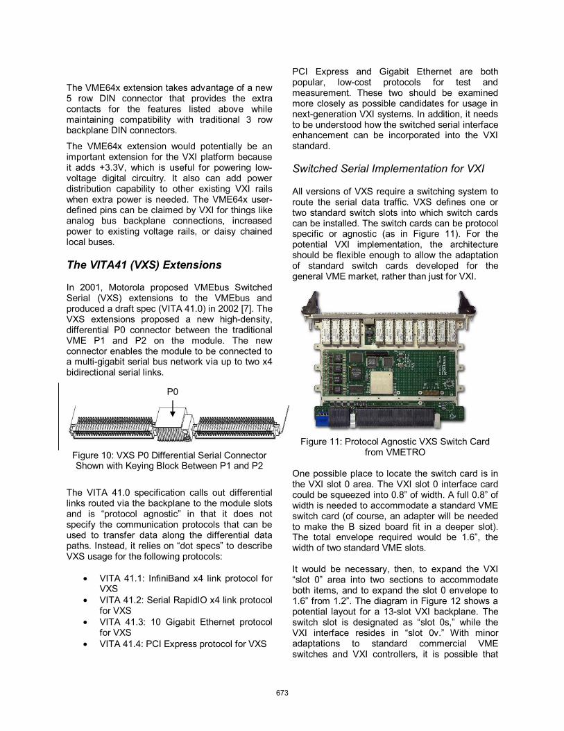
All versions of VXS require a switching system to route the serial data traffic. VXS defines one or two standard switch slots into which switch cards can be installed. The switch cards can be protocol specific or agnostic (as in Figure 11). For the potential VXI implementation, the architecture should be flexible enough to allow the adaptation of standard switch cards developed for the general VME market, rather than just for VXI.
Figure 11: Protocol Agnostic VXS Switch Card from VMETRO
One possible place to locate the switch card is in the VXI slot 0 area. The VXI slot 0 interface card could be squeezed into 0.8” of width. A full 0.8” of width is needed to accommodate a standard VME switch card (of course, an adapter will be needed to make the B sized board fit in a deeper slot). The total envelope required would be 1.6”, the width of two standard VME slots.
It would be necessary, then, to expand the VXI “slot 0” area into two sections to accommodate both items, and to expand the slot 0 envelope to 1.6” from 1.2”. The diagram in Figure 12 shows a potential layout for a 13-slot VXI backplane. The switch slot is designated as “slot 0s,” while the VXI interface resides in “slot 0v.” With minor adaptations to standard commercial VME switches and VXI controllers, it is possible that
P0
673

VXS could be added to VXI without having to design much new hardware, aside from the new backplane and power that would be required.
Figure 12: Potential Implementation of VXS Architecture on a 13-Slot VXI Backplane with 24 x4 Data Links (2 per J0 Connector)
The proposed switching architecture has the following advantages:
• It only adds 0.4” of width to the VXI width envelope
• It makes every VXI application slot into a potential “payload” slot with connectivity to two x4 data links or eight x1 links
• It makes use of standard VXI controllers and VME switches, but with some minor mechanical changes
• It preserves compatibility with legacy VXI • It adds +3.3V to power the high speed
data links
VITA 41.3 Gigabit Ethernet for VXI
The VXS architecture allows up to two x4 bidirectional data links to each payload slot. This allows up to eight Gigabit Ethernet connections or two 10 Gigabit Ethernet connections for an estimated cumulative data bandwidth of about 28 GB/s. VITA 41.3 defines the interfaces for using Gigabit Ethernet or 10 Gigabit Ethernet with the VXS architecture. This architecture could be imported from VITA 41.0 and 41.3 for use in next-generation VXI systems.
The advantages of supporting VITA 41.3 in a VXI extension are:
• It has high bandwidth for data transfer intensive applications
• It enables high speed remote access over LAN, WAN or the internet
• Instruments can support the LAN Extensions for Instruments (LXI) standard for easy test system integration
VITA 41.4 PCI Express for VXI
PCI Express is Intel’s choice for a scalable serial architecture to replace the aging, parallel PCI bus, while maintaining backward software compatibility with it. The VXS architecture specifies up to two x4 PCI Express data links to each payload slot with an estimated cumulative bandwidth of about 48 GB/s. This cumulative throughput is especially useful when data converters are used to offload to data processing unit(s), and the VME world provides many COTS options for this.
Since PCI Express is software compatible with PCI, migration from PCI to PCI Express less costly, and this will help fuel the growth of PCI
674

Express based products. The VITA 41.0 and 41.4 architecture could be implemented in next-generation VXI systems.
The advantages of supporting VITA 41.4 in a VXI extension are:
• Compact PCI and PXI instruments could be used in a VXI system with a simple PCI Express-PCI bridge adapter
• Compact PCI Express and PXI Express products could be used in VXI with a simple mechanical adapter
• It has high bandwidth for data transfer intensive applications like SI
PXI Express and LXI Compatibility
The PXI Express and LXI standards have high-performance synchronization capabilities and functionality that facilitate easy test system integration. Here is a list of some of the concepts from these standards that might make sense for a future VXI enhancement:
• LXI Enhancements o Wired trigger bus o IEEE-1588 LAN synchronization o Web page interface o IVI interface o LAN Discovery
• PXI Enhancements o LVDS triggers o Star triggering o 100 MHz clock o LVDS synchronization bus
SUMMARY
With a few small exceptions, the VXI platform has been successful at meeting its goals for the first 20 years of its existence. PXI and LXI do not replace the need for VXI. They underscore the need for the VXI platform to update itself to meet the challenges of the next 20 years. The best path for the VXI consortium would be to form a working group to discuss incorporating some of the VITA 41 extensions to VME, as well as to incorporate some of the nifty new features from LXI and PXI Express.
REFERENCES
[1] History of VXI, © 2003-2004. VXIbus Consortium.
[2] Ross, Bill, DoD ATS Liaison, 2004.
[3] PXI Express Hardware Specification Rev 1.0,© 2005, PXI Systems Alliance.
[4] Poole, David and Rennard, Bob, Synthetic Instruments and LXI, April 2005, Evaluation Engineering.
[5] Jonsson, Dr. L.E., and Magro, Dr. W.R., Comparative Performance of InfiniBand Architecture and Gigabit Ethernet Interconnects on Intel® Itanium® 2 Microarchitecture-Based Clusters, Intel Americas.
[6] American National Standard for VME64 Extensions, © 1998. VMEbus International Trade Association.
[7] VXS VMEbus Switched Serial Standard, © 2002. Motorola and the VMEbus International Trade Association.
675