VxBPMN Designer: A Graphical Tool for Customizable Process Models Using...
78
VxBPMN Designer: A Graphical Tool for Customizable Process Models Using the PVDI Framework Piet den Dulk Master’s thesis Computing science, University of Groningen Supervisor: Prof. Marco Aiello Co-supervisor: Prof. Alexandru C. Telea November 29, 2013
Transcript of VxBPMN Designer: A Graphical Tool for Customizable Process Models Using...

VxBPMN Designer: A Graphical Tool for
Customizable Process Models Using the PVDI
Framework
Piet den DulkMaster’s thesis
Computing science, University of GroningenSupervisor: Prof. Marco Aiello
Co-supervisor: Prof. Alexandru C. Telea
November 29, 2013


Abstract
In today’s industry, where fast and efficient delivery of high-quality productsand services is a demand, business processes are at the core of medium andlarge-scale organizations. Assisted by IT systems, business processes coordi-nate human and automated activities, to fulfill the goal products and servicedelivery. Since business processes reflect organizational operations, businessprocesses need to stay in synchronization with the constant changing envi-ronment of an organization. However, many standards and technologies usedin today’s industry offer little support for management of change and vari-ability in business processes. In addition, some organizations are structuredwith a separation of authority. One such organization is the government andits connected municipalities. Municipalities have to implement processes tosupport their (digital) services. These processes have to adhere to chang-ing laws established by the government. In addition, municipalities greatlydiffer from one another. This thesis presents a graphical tool for modelingbusiness processes, enhanced with template design and formal verificationof process variants. The purpose is to provide a demonstration of the Pro-cess Variability - Declarative’n’Imperative (PVDI) framework. The PVDIframework enriches a process modeling language with syntax for expressingvariability as constraints. In addition, the PVDI framework provides algo-rithms for verification of process variants derived from templates. The tooldemonstrates that business processes can be templatized, customized andchecked on correctness using formal verification. Additionally, the tool iscompatible with other process modeling tools and business process manage-ment systems such as Cordys BOP. This compatibility allows to simulate aprocess management life cycle that includes variability modeling and pro-cess customization. Compatibility with Cordys BOP is achieved by usingthe Business Process Model and Notation for design of process models, andthe XML Process Definition Language for interchange of process modelsamong different tools.


Contents
1 Introduction 11.1 Context . . . . . . . . . . . . . . . . . . . . . . . . . . . . . . 11.2 Problem Statement . . . . . . . . . . . . . . . . . . . . . . . . 21.3 Research Question . . . . . . . . . . . . . . . . . . . . . . . . 31.4 Thesis Organization . . . . . . . . . . . . . . . . . . . . . . . 4
2 Case Study 52.1 The SAS-LeG Project . . . . . . . . . . . . . . . . . . . . . . 52.2 Scenario: Subsidized Wheelchairs . . . . . . . . . . . . . . . . 6
3 Background 83.1 Business Processes . . . . . . . . . . . . . . . . . . . . . . . . 8
3.1.1 Business Processes in Context . . . . . . . . . . . . . . 83.1.2 Business Process Model and Notation . . . . . . . . . 103.1.3 XML Process Definition Language . . . . . . . . . . . 113.1.4 Business Process Management . . . . . . . . . . . . . 11
3.2 Web Services . . . . . . . . . . . . . . . . . . . . . . . . . . . 143.3 Business Process Variability . . . . . . . . . . . . . . . . . . . 153.4 Computation Tree Logic(+) . . . . . . . . . . . . . . . . . . . 16
4 The PVDI Framework 204.1 Formal Process Definition . . . . . . . . . . . . . . . . . . . . 204.2 PVDI Templates . . . . . . . . . . . . . . . . . . . . . . . . . 214.3 Flow Constraint . . . . . . . . . . . . . . . . . . . . . . . . . 224.4 Parallel Constraint . . . . . . . . . . . . . . . . . . . . . . . . 244.5 Group Constraint . . . . . . . . . . . . . . . . . . . . . . . . . 25
4.5.1 Frozen Group . . . . . . . . . . . . . . . . . . . . . . . 254.5.2 Semi-frozen Group . . . . . . . . . . . . . . . . . . . . 26
5 Realization 285.1 Architecture within the SAS-LeG Context . . . . . . . . . . . 28
5.1.1 The Process Pipeline . . . . . . . . . . . . . . . . . . . 285.1.2 System Overview . . . . . . . . . . . . . . . . . . . . . 29
5.2 Functional Requirements . . . . . . . . . . . . . . . . . . . . . 32
v
CONTENTS
5.2.1 Use Case Diagram: System . . . . . . . . . . . . . . . 345.2.2 Use Case Diagram: Process Modeling Tool . . . . . . 34
5.3 Development Challenges . . . . . . . . . . . . . . . . . . . . . 365.4 Implementation . . . . . . . . . . . . . . . . . . . . . . . . . . 38
6 Software Prototype 396.1 VxBPMN Designer . . . . . . . . . . . . . . . . . . . . . . . . 396.2 Demonstrating PVDI’s Template Features . . . . . . . . . . . 41
6.2.1 Flow Constraint . . . . . . . . . . . . . . . . . . . . . 416.2.2 Parallel Constraint . . . . . . . . . . . . . . . . . . . . 446.2.3 Frozen Group . . . . . . . . . . . . . . . . . . . . . . . 446.2.4 Optional Activities . . . . . . . . . . . . . . . . . . . . 476.2.5 Weak Link . . . . . . . . . . . . . . . . . . . . . . . . 506.2.6 Floating Activities . . . . . . . . . . . . . . . . . . . . 52
6.3 Tool Compatibility . . . . . . . . . . . . . . . . . . . . . . . . 55
7 Conclusions 607.1 Future Work . . . . . . . . . . . . . . . . . . . . . . . . . . . 63
7.1.1 Research Opportunities . . . . . . . . . . . . . . . . . 637.1.2 Tool Improvements . . . . . . . . . . . . . . . . . . . . 65
Bibliography 67
vi

List of Figures
2.1 Generic process model[1]. . . . . . . . . . . . . . . . . . . . . 72.2 Process variant [1]. . . . . . . . . . . . . . . . . . . . . . . . . 7
3.1 A formal structure of a business process [22]. . . . . . . . . . 103.2 Core set of BPMN elements [15]. . . . . . . . . . . . . . . . . 113.3 The BPM life cycle [35]. . . . . . . . . . . . . . . . . . . . . . 123.4 The model checking approach [26]. . . . . . . . . . . . . . . . 173.5 Semantics of CTL visualized [2]. . . . . . . . . . . . . . . . . 18
4.1 Flow constraint [14]. . . . . . . . . . . . . . . . . . . . . . . . 244.2 Parallel constraint [14]. . . . . . . . . . . . . . . . . . . . . . . 244.3 Frozen group (left) and semi-frozen group (right) [14]. . . . . 25
5.1 The process pipeline in e-Government. . . . . . . . . . . . . . 305.2 Deployment diagram of the SAS-LeG architecture. . . . . . . 335.3 Use case diagram: system. . . . . . . . . . . . . . . . . . . . . 355.4 Use case diagram: process modeling tool. . . . . . . . . . . . 36
6.1 VxBPMN designer. . . . . . . . . . . . . . . . . . . . . . . . . 406.2 Flow constraint between activities a and b. . . . . . . . . . . 426.3 Flow constraint not satisfied. . . . . . . . . . . . . . . . . . . 436.4 Parallel constraint between activities a and b. . . . . . . . . . 456.5 Parallel constraint violated. . . . . . . . . . . . . . . . . . . . 466.6 Frozen group. . . . . . . . . . . . . . . . . . . . . . . . . . . . 486.7 Frozen group violated by activity g. . . . . . . . . . . . . . . 496.8 Activity b is optional. . . . . . . . . . . . . . . . . . . . . . . 506.9 Optional activity b removed. . . . . . . . . . . . . . . . . . . . 516.10 Semi-frozen group with two weak links. . . . . . . . . . . . . 536.11 Weak link allows insertion of activities. . . . . . . . . . . . . . 546.12 Activity b is floating. . . . . . . . . . . . . . . . . . . . . . . . 566.13 Floating activity b can be moved. . . . . . . . . . . . . . . . . 576.14 Imported process model in Cordys BOP. . . . . . . . . . . . . 586.15 Imported process model in Bizagi process modeler. . . . . . . 59
vii


Chapter 1
Introduction
Ever since the early days of manufacturing, efficiency of production is keyto success. In the industrial era, pioneers like Adam Smith and FrederickTaylor introduced scientific methods for optimization and management ofmanufacturing processes. Striving for efficient processes, leads to fasterproduction, less resources, less waste, faster time-to-market and ultimatelyto competitive advantage and revenues.
1.1 Context
The digital era and today’s worldwide economy has led to a wide range ofnew (business) opportunities. Business processes are at the core of mediumand large-scale organizations, and IT supported infrastructures of these or-ganizations are highly process driven [1]. Hammer and Champy [16] definea business process as: ”a collection of activities that takes one or more kindsof input and creates an output that is of value to the customer.” Examplesof business processes are: purchase orders, flight booking, stock control andfinancial transactions.
Various languages exist for designing and executing business processes, suchas the Business Process Model and Notation (BPMN) [15], Event DrivenProcess Chains (EPCs) [19, 38] and the Business Process Execution Lan-guage (BPEL) [24]. BPMN is one of the prominent languages for designof process models in the business domain [29]. However, most process lan-guages such as BPMN, EPCs and BPEL lack support for modeling partsof a process that are subject to change [38, 42]. Whenever a change is re-quired, process models need to be changed manually. Consequently, eitherall variations are modeled in one monolithic process model, or many co-existing but similar process models need to be maintained simultaneously[42]. Since process models represent the operations of an organization, a(subtle) change can have significant impact on the entire organization and
1

1.2. PROBLEM STATEMENT
beyond [40]. Fast response to change is difficult when business processes arepervasively implemented. Preferably, business processes need to stay syn-chronized with the organization and adapt to changing requirements, suchas new business opportunities, customer demand, legislation and organiza-tional restructuring. Process models become unmanageable without explicitsupport of variability.
According to Santos, et al. [32], ”variability in business process models,consists of defining alternative paths of execution”, and occurs in two di-mensions [42]. First, variability occurs over time, which is usually caused bychanging requirements, resulting in process evolution. Second, variabilityoccurs within a domain space, which is usually caused when offering cus-tomized products and services, resulting in a process family. The ability toexpress explicit variability in process models, requires that a process lan-guage has syntax for specifying alternative paths of execution.
National governments and their connected municipalities, face the challengeof reusing process models as much as possible while allowing a degree ofcustomization, such that different municipalities can offer the same servicewhile adhering to a national legislation. Each municipality may differ insize, resources and IT systems. In addition, there are (subtle) differencesof how legislation is allowed to be implemented. Since each municipalityis different, no manageable process model suits all municipalities. Whilethe overall structure of a process model must be preserved, variations arerequired such that a process model can be adapted to the needs of any mu-nicipality. Preserving the overall structure of a process model while allowinga degree of variation, requires separation of process modeling in to, designand customization of process models. Furthermore, other domains such ashealth care and the automotive industry, have similar scenario’s [1, 42].
1.2 Problem Statement
Most process languages such as BPMN and EPCs were not designed withvariability modeling in mind. To account for variability, either a new pro-cess language has to be developed from scratch, or an existing process lan-guage needs to be extended with syntax for variability modeling. Varioustechniques to address process variability have been proposed in literature,such as feature diagrams and variation points (Feature-EPC [42], VxBPEL[4]), inheritance (C-EPCs [37]), Petri nets [46] and declarative specifications(ConDec [27], DECLARE [28]). However, none of the proposed techniqueshave yet established into an industry standard. In addition, process lan-guages exist in design, execution and interchange languages [20]. Obviously,the need for process variability affects business process information systems,as these systems were developed without support for (standardized) explicit
2

1.3. RESEARCH QUESTION
variability management.
A common problem of modeling variability in business process models is:a) to manage large sets of different versions of a process model, and b) todeal with unforeseen situations and changing requirements. A method forbusiness process variability is the use of a reference process such as C-EPCs[31, 40]. A reference process is a generic model, allowing customization ofspecific process models. Many implementations such as C-EPCs, Feature-EPC [42] and VxBPEL [4] use imperative methods to specify variability.Imperative methods focus on how tasks of a process are performed [1, 14].In practice, imperative variability requires to specify all possible variationsin advance [14]. Imperative variability is far from flexible, since theoreti-cally, a reference process needs to hold an infinite amount of possible processvariants. Flexibility of process models is required for the government andmunicipalities scenario (see Section 1.1). In such scenario’s, many differentversions of a process model exist, since each municipality is different. Usingan imperative method for modeling variability is practically infeasible whena process designer has to specify large sets of differences.
1.3 Research Question
Software As Service for the varying needs of Local e-Governments (SAS-LeG) [25], is a project that aims to improve (digital) service offering of theDutch municipalities, by proposing software services and business processtechnology. Within the SAS-LeG project, Aiello, et al. [1] compiled a listof requirements for explicit process variability. The requirements are cat-egorized by: expressive power, variability techniques, service requirements,consistency and fault handling, and evolution requirements. Moreover, in[1] different tools and frameworks such as VxBPEL [4], ADEPT [7] and DE-CLARE [28] are evaluated and compared with respect to the requirementsfor explicit process variability. In conclusion, there are no frameworks nortools available that support all listed requirements of variability manage-ment [1]. Groefsema, et al. [14] proposed the Process Variability - Declara-tive’n’Imperative (PVDI) framework, which focuses on a subset of the listedrequirements from [1], that relate to process modeling. Similar to impera-tive methods (see Section 1.2) for process variability, the PVDI frameworkalso works with a reference model. However, in contrast to an imperativemethod, the PVDI framework offers a higher degree of flexibility, by com-bining imperative and declarative approaches as a specification for modelingof process variability. Instead of specifying all alternative tasks in a processmodel using an imperative method, a declarative specification defines rulesfor what must be satisfied, limiting the boundaries of a process model [1].A tool for demonstrating and testing the PVDI framework, however, is still
3

1.4. THESIS ORGANIZATION
missing. Furthermore, variability management requires change to the lifecycle of business process management [1].
The main research question of this thesis is:Would a software prototype, demonstrate the PVDI framework as a candi-date solution for modeling explicit variability in business process models?
From this research question, the following sub questions are derived:
1. How would process variability using the PVDI framework change thestandard life cycle of business process management?
2. What is needed to achieve compatibility with other process tools, suchthat the business process life cycle incorporating the PVDI method canbe simulated?
3. Does an automated model checker confirms formal verification of thePVDI framework on customized process models?
The objective of this thesis is to introduce a software prototype of a processmodeling tool that implements the PVDI framework.
1.4 Thesis Organization
This thesis is organized as follows. First, in Chapter 2 the SAS-LeG projectis introduced, followed by a case study. The case study illustrates the prob-lem statement, and is used as an example throughout this thesis. In Chapter3, background information is given about: business processes, Web services,business process variability and Computation Tree Logic+. The state of theart is provided in Chapter 4, which explores the PVDI framework. First, aformal definition of a process is given, followed by an early specification ofthe PVDI framework. Chapter 5 addresses the realization of the solutionand a software prototype is showcased in Chapter 6. Finally, in Chapter7 the research questions are answered and challenges for future work arepresented.
4

Chapter 2
Case Study
Because this thesis contributes to the SAS-LeG project, the objective ofthe SAS-LeG project needs a brief introduction. The problem faced by theDutch government and its connected municipalities, is then illustrated witha scenario.
2.1 The SAS-LeG Project
Software As Service for the varying needs of Local e-Governments (SAS-LeG) [25] is a project that aims to improve (digital) service offering of theDutch municipalities. The project is funded by the Netherlands Organiza-tion for Scientific Research, and is a collaboration between the Universityof Groningen, Cordys and several municipalities of the north of the Nether-lands.
Municipalities have to implement national laws, to service their citizens.Currently, municipalities are responsible for their own activities to supportthese national laws. Each municipality uses a lot of resources to implementand maintain the national laws. Some municipalities may have processesthat coordinate their activities, whereas others still deliver their serviceswith ad hoc performed activities. Because each municipality implementsthe same national law, the activities and processes that support the law,share a lot of commonalities. Whenever a law is changed, or a new law isprescribed by the Dutch government, each municipality implements it indi-vidually. Since the Netherlands has more than 400 different municipalities,a lot of work is done redundantly. This inefficiency calls for a solution, suchthat national laws are uniform and correctly implemented by all decentral-ized municipalities. Section 2.2 illustrates a scenario of this problem.
The SAS-LeG project proposes Software as a Service (SaaS) to improve (dig-ital) service offering of the Dutch municipalities [25]. SaaS is an approach
5

2.2. SCENARIO: SUBSIDIZED WHEELCHAIRS
to stimulate reuse of (distributed) IT components and legacy systems. Theobjective is to implement the law once and offer it as a customizable ser-vice [25]. A customizable service can then be aligned to the organizationalstructure of each municipality. Section 3.2 explains (digital) services in moredetail.
2.2 Scenario: Subsidized Wheelchairs
The Netherlands counts more than 400 different municipalities. These mu-nicipalities all vary in size, (human) resources and IT systems. In addition,municipalities have their own local rules. Yet, each municipality has to im-plement the same law prescribed by the Dutch government. One such lawgoverns provision of subsidized wheelchairs. With this law, handicappedpeople can request a wheelchair from their respective municipality. To qual-ify for a subsidized wheelchair, a request has to meet certain criteria. Whena municipality receives a request, a process is initiated and handles the re-quest.
Figure 2.1 depicts a graphical representation of a process for granting awheelchair. The circle at the left side represents the start of the process,and the circle at the right side is where the process terminates. The rectan-gle and diamond shapes represent activities, and the arrows represent flowof the process. The process coordinates activities that are executed in acertain order. Activities can be either automated tasks or human activities.For example, an activity could be a ”home visit”, where an employee visitsthe person who requested a wheelchair. Eventually, the process terminatesand an outcome for granting a wheelchair is based on how the process isexecuted.
Municipalities greatly differ from each other, and so do their activities. Fig-ure 2.2 depicts a similar, but slightly different process model. The overallstructure bears resemblance with the structure of the process model in Fig-ure 2.1, but has a slightly different composition of activities. For example,some municipalities prefer to execute a home visit, whereas others do not.In Figure 2.2 a municipality executes a home visit, whereas another munici-pality following the process model of Figure 2.1, omits this activity. Anotheractivity where municipalities may differ, is the ”refer to CIZ” activity, wherean audit on the type and amount of health care is done by an external or-ganization. The last difference between both processes, is a check on theage of a person when a wheelchair is granted for free. As the borderlinefor age is not prescribed by the law, the condition for it, may differ frommunicipality to municipality. In the process of Figure 2.1, a person has tobe at least 70 years old, whereas in Figure 2.2 a particular municipality hadchosen to soften the condition for age, to 65.
6

2.2. SCENARIO: SUBSIDIZED WHEELCHAIRS
Figure 2.1: Generic process model[1].
Figure 2.2: Process variant [1].
7

Chapter 3
Background
This chapter provides background information about: business processes,Web services, and business process variability. Lastly, a temporal logic usedfor formal model checking called Computation Tree Logic+ is explained,which is the foundation of the PVDI framework (see Chapter 4).
3.1 Business Processes
The general topic of business processes is explored in this section. Thefollowing subsections introduce business processes, Business Process Modeland Notation, XML Process Definition Language and business process man-agement.
3.1.1 Business Processes in Context
Business processes are at the core of today’s medium and large-scale orga-nizations [1]. The outcome of a business process can be a product, serviceor supporting process. An important factor of managing business activitiesrequires that an organization is conscious about the processes within andacross the organizational. A process can be monitored to find bottlenecksfor improvement. Management of processes becomes more important as anorganization increases in size as a mechanism for strategic and operationsmanagement. A lot of work is done redundant without a process to befollowed. In literature various definitions of a business process are stated[13, 20]. Besides the definition stated by Hammer and Champy [16] (seeSection 1.1), the following two definitions, among more, are used in litera-ture.
According to Davenport [8], ”a business process is a structured, measuredset of activities designed to produce a specific output for a particular cus-tomer or market. It implies a strong emphasis on how work is done within
8

3.1. BUSINESS PROCESSES
an organization, in contrast to a product focus’s emphasis on what. A pro-cess is thus a specific ordering of work activities across time and space, witha beginning and an end, and clearly defined inputs and outputs: a structurefor action.”
Smith and Fingar [34] defined a business process as: “a complete and dy-namically coordinated set of collaborative and transactional activities thatdeliver value to customers.”
Let’s consider a manufacturing process. The execution of a manufacturingprocess is fixed and known in advance. The steps taken for assembly ofa product are exactly followed as the procedure described by the process.Each product of the same type is manufactured the exact same way. Bymonitoring the production process, the process can be optimized to raiseperformance, resulting in faster and cheaper production.
Similar to optimization of manufacturing processes, optimizing a businessprocess may lead to efficient use of resources. In contrast to traditionalmanufacturing processes, however, a business process is of less rigid nature.Business processes have a less predictable character, and require more flex-ibility. Business processes have to support various forms of communicationsuch as machine to machine communication, human-machine communica-tion and human to human communication. Management of business pro-cesses (see Section 3.1.4) requires commitment to capture knowledge of theactivities and communication flows within an organization. In contrary totraditional manufacturing processes, a human-centric system controlled bya business process management system, requires a degree of flexibility toaccommodate for human work.
Business processes can be either short or long lived. A short-lived businessprocess is entirely composed of automated activities such that it respondswithin the interaction of a Web form. The activities of a business processare often implemented as Web services (see Section 3.2), and a business pro-cess is often invoked as a Web service itself. An example of a short-livedbusiness process is a flight booking service. A flight booking service invokesvarious other Web services to arrange a flight without human intervention,yet providing the necessary details. Obviously, the execution of a businessprocess for a flight booking service should respond shortly after a customerfilled in a Web form with information. A long-lived business process doesn’thave to terminate shortly after it is initiated, and may take interventionof human activity. Examples of long-lived business processes are manufac-turing processes, product delivery and provision of subsidized wheelchairs.
9

3.1. BUSINESS PROCESSES
Figure 3.1: A formal structure of a business process [22].
Product delivery, e.g., involves activities such as transportation.
Furthermore, the terms ”process” and ”business process” are used inter-changeable in the field of business process management. Ryan K. and L. Ko[20] state that, ”a process can be any human endeavor. A business processis a process within a business context.” In this thesis the term ”process”is generally used and the term ”business process” is used when specificallyreferring to a process in a business context. For the PVDI framework (seeChapter 4) a formal definition of a business process is required. Figure 3.1,depicts an abstraction from a specific business process model. The abstrac-tion has a more general structure that can be formalized by a data structure.Section 4.1 introduces a formal definition of a (business) process.
3.1.2 Business Process Model and Notation
Traditionally, business and IT staff have different viewpoints of business pro-cesses and did not share the same vocabulary, which often causes a mismatchin communication [20]. The Business Process Model and Notation (BPMN)[15] is a standard specified by the Object Management Group (OMG) fordesigning Business Process Diagrams (BPD’s). With BPMN, different pro-fessionals such as business analysts, managers and IT staff [20, 21, 33] havea shared vocabulary. BPMN is one of the most popular languages for mod-eling BPD’s [29] and is supported by many process modeling tools [21, 29]such as Cordys BOP [6], Bizagi Process Modeler [3], Intalio BPMS [17] andTibco Business Studio [36].
Figure 3.2 depicts the core set of BPMN elements where flow objects (nodes)and connecting objects (edges) are the most used modeling constructs of thelanguage. Nodes represent the tasks of a business process, which can be ac-tivities, gateways or events. Tasks are the atoms of a process model, and areinterconnected by connectors, which specify flow. Furthermore, BPMN hasswim lanes and grouping elements used to organize flow objects into organi-zational units and categories respectively. However, BPMN lacks support ofbusiness execution rules [29], nor is a machine readable format (originally)prescribed. A standardized machine readable format is required for interop-
10

3.1. BUSINESS PROCESSES
Figure 3.2: Core set of BPMN elements [15].
erability of process modeling tools from different vendors. The absence ofa format for storing BPD’s has led to XML-based languages such as XPDL[5] (see Section 3.1.3).
3.1.3 XML Process Definition Language
BPMN (see Section 3.1.2) originally did not come with a machine readableformat. Using graphical constructs, the BPMN specification specifies syntaxand semantics of how diagrams can be composed. However the specificationis independent of the underlying technology used for supporting BPMN dia-grams. Specified by the Workflow Management Coalition (WfMC), the XMLProcess Definition Language (XPDL) [5] is a standardized XML-based for-mat for marshaling business process diagrams with an emphasis on BPMNdiagrams. XPDL has support for storing both graphical and execution infor-mation of BPMN graphs. With the ability of storing graphical informationin XPDL, different BPMN tools can interchange process models. With astandardized format for storing process models, vendors can make their toolscompatible with tools and business process platforms from other vendors.Because XPDL is XML based, XPDL can be extended with new featuressuch as constructs of the PVDI framework (see Section 1.3). In addition,XPDL provides functionality for storage of tool specific properties.
3.1.4 Business Process Management
Ad hoc workflows might be sufficient or even an advantage for small or-ganizations. However, process management becomes a necessity for largeorganizations, to have strategic control over the operations performed. Man-agement of business processes is called business process management (BPM).
11
3.1. BUSINESS PROCESSES
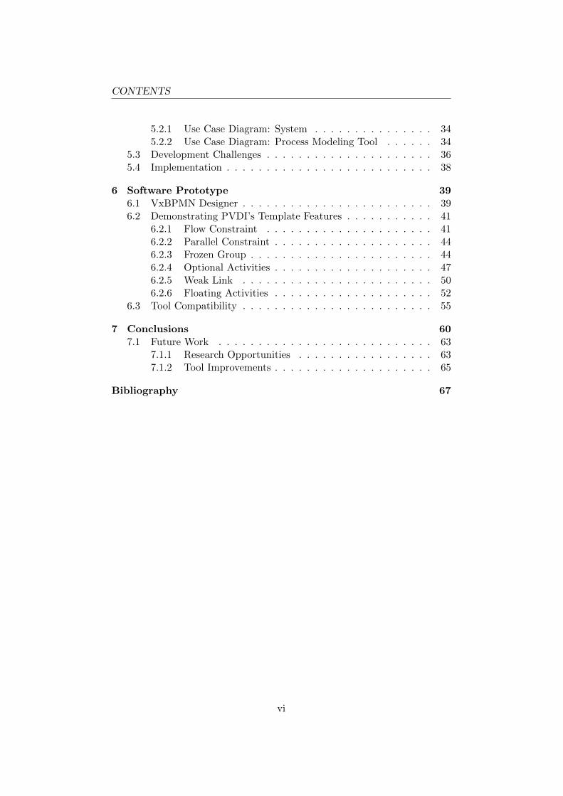
Figure 3.3: The BPM life cycle [35].
Van der Aalst, et al. [41] defined BPM as ”supporting business processesusing methods, techniques and software to design, enact, control and an-alyze operational processes involving humans, organizations, applications,documents and other sources of information.”
The idea behind BPM is to acquire high-level control of the operationswithin an organization at a management level. A diagrammatic processmodel provides a bird’s-eye view of the activities within an organization.When monitoring a process, bottlenecks can be found, which could indicateopportunities for optimization. Figure 3.3 depicts the BPM life cycle [41].This figure shows four phases in a closed-loop life cycle that are applied bymany BPM adopters. The next subsections briefly introduce each phase ofthe life cycle that business processes undergo in BPM.
Design and Model
The first step in BPM is to get a diagrammatic overview of the processesrunning in an organization. A business process diagram is a visual repre-sentation of a process model. Before a process model can be designed, thecurrent situation is analyzed first. A business process model can be designedfrom specified requirements and data collected during observations. In thefirst iteration of the life cycle, the process model is drawn from scratch. Spe-cific details may remain unknown during this phase. A business architectfirst draws an initial design on a paper sheet or using a process modelingtool. In subsequent iterations of the life cycle, the process model is revisedfor optimization.
Process models are designed in a (standardized) modeling language such asBPMN and EPC, which let different experts work on the same process mod-els. A wide variety of graphical modeling tools exist for design of businessprocess models [21, 29], such as Cordys BOP [6], Bizagi Process Modeler[3], Intalio BPMS [17] and Tibco Business Studio [36].
12

3.1. BUSINESS PROCESSES
Develop, Test and Deploy
A business process diagram is a mere visual representation of a processmodel. Therefore, a process model needs to be coupled with executabletasks, such that a process can interact with real world activities. Executabletasks can be either human work or automated activities. During this phase,coupling of executable activities with the respective process model takesplace.
A unit of work can be reused when there is clear definition that has: a) aninterface or contract representing a unit of work, and b) an implementationof the respective unit of work that conforms its interface or contract. Theimplementation of a unit of work can be an automated or a human activity.For example, at some point during execution of a business process, an em-ployee performs some activity and has to fill in a (digital) form with the datagathered during that activity. The digital form acts as an interface betweenthe human activity and the business process in execution. Another exampleis a Web service [45] (see Section 3.2) that is invoked via an interface suchas WSDL [44].
Furthermore, most BPM platforms such as Cordys BOP [6], offer simulationtools such that process models can be tested. The flow of communicationmust be accurate between different executable tasks, as the output from oneactivity of the process is input to another activity. Finally, when the testcases are successfully passed, a process model can be deployed for actualusage.
Execute
A deployed business process model coordinates the various activities of anorganization. When a business process is started, an instance of the busi-ness process model is created. The instance is the actual execution of aprocess. Multiple instances of the same business process can coexist and arehandled in parallel. For example, consider a business process for a subsi-dized wheelchair (see Section 2.2). When a citizen requests a wheelchair, aninstance of the respective business process model is created. When anothercitizen requests a wheelchair, a second instance of the same business processmodel is started for that request. Each request is handled by a separateinstance of a process model. The amount of process instances depends onthe amount of requests to be processed.
Analyze and Optimize
When instances of a process model are running, the execution of these pro-cesses can be closely monitored. Also, the state of a process instance can
13

3.2. WEB SERVICES
be analyzed. Quantitative data can be collected when multiple instancesare running. With quantitative data, statistics can be applied to analyzethe efficiency and effectiveness of the respective process. When analyzinga process, bottlenecks can be found, which might indicate opportunitiesfor optimization. Moreover, as requirements change and new technologiesemerge, these changes might affect the process model. The analyzed dataacquired during this phase can then be used as input for the next iterationof the process life cycle as the closed-loop in Figure 3.3 suggests.
3.2 Web Services
The SAS-LeG project (see Section 2.1) proposes SaaS as a software tech-nology model, to implement the law once and offer it as a customizableservice to the municipalities of the Netherlands [25]. SaaS is a softwaredelivery model, which is often implemented using Web service technology.Web services [45] are loosely coupled software components distributed overa network such as the Internet. ”Loosely coupled”, means that software sys-tems using Web services, are not dependent on the implementation of a Webservice. Instead, systems that use Web services, only know the interface of aWeb service. The interface describes the functionality of a Web service. Theadvantage of loose coupling, is that the implementation of a Web service canbe replaced by another implementation, without any modification requiredon dependent software systems that utilize Web services.
The interface of a Web service is often accomplished trough the Web ServiceDescription Language (WSDL) [44]. WSDL is an XML-based language fordescribing the location and functionality of a Web service. Similar to inter-faces used in programming languages, a WSDL file contains declarations offunctions that are implemented by the respective Web service. A standard-ized format for accessing Web services is the Simple Object Access Protocol(SOAP) [43]. With SOAP, data can be interchanged between different in-formation systems without ambiguity, since the type of data is specified inthe SOAP standard, implemented by both client and server software.
Web services can be seen as autonomous, distributed building blocks thatare hosted on a Web server from which they can be accessed by other soft-ware clients simultaneously. An example of a Web service is a service forretrieving weather information. A weather station might wish to make theirweather information digitally available to other applications. Web servicescan be either atomic or a composition of other Web services. For example,an atomic Web service retrieves weather information from a database of theweather station, and then forwards this information to requesting softwareclients. A decomposed Web service invokes other Web services to createrich/ new content. For example, a Web service for travel information needs
14

3.3. BUSINESS PROCESS VARIABILITY
weather information in addition to other information such as destinationand date of arrival. The travel information service is a composite Web ser-vice composed from other atomic and composite Web services. The travelWeb service on its turn can be used by different travel agencies.
3.3 Business Process Variability
Current BPM standards and technologies offer little support for variabil-ity of process models [40]. Business activities within (large) organizationsare difficult to maintain and change. As described in Section 3.1.4, theBPM life cycle starts with design of process models. However, most processlanguages such as BPMN and EPC offer little to no support for design ofchange and variation of process models [38, 42]. As a result, process modelsare limited in their configuration [40] abilities. Process languages withoutsupport of explicit variability, are called non-configurable process languages[42]. Without functionality for explicit design of variable activities, the finalprocess model has a rigid structure. This rigid process model is passed onto the next phase in a process life cycle. Responding to change becomesproblematic when rigid process models are propagated through the processlife cycle. When a process model finally reaches an operating environment,execution of a business process can be predicted in advance [1, 30, 39]. Pre-diction of process execution is a desirable requirement for BPM, but whenprocesses are pervasively implemented, alignment with a constant changingenvironment becomes difficult.
With non-configurable process languages such as BPMN and EPC, vari-ability is implicitly designed within the process model via the use of choiceconstructs such as OR gates. Alternatively, slightly different but similarprocess models are designed [42] to cope with variability. The first methodleads to an incomprehensible process model, whereas the latter method re-sults in maintenance problems. A process increases in size and complexitywhen all variations are designed in one large process. When a process hasto incorporate all different variations, a process model increases complexity,which affects readability. The latter case leads to maintenance problemswhen having several, but similar process models.
Santos, et al. [32], state that: ”variability in business process models, con-sists of defining alternative paths of execution” and occurs in two dimensions[42]. First, variation occurs over time resulting in process evolution. Processevolution happens when a process model needs to be changed while alreadybeing in operation. For example to improve a bottleneck in the process ora change in legislation requires a change in the process. The second dimen-sion is variability within the process model resulting in a process family.Management of variation in these two dimensions, enables fast response to:
15

3.4. COMPUTATION TREE LOGIC(+)
product/ service demand, innovation and change in regulations.
Another distinction of variability can be made between design and run-timeprocess variability. Design-time variability requires expressive power andease of use for designing process families. The designer of a process modelcan foresee certain variations of the process and models the variable partsaccordingly. Run-time variability concerns process execution models, in-stead of process diagrams. On the execution level, variation exposes thatcannot be foreseen by the process designer. The execution aspects concernhow activities should be performed, whereas variation of process diagramsconcern what should be done. Process modelers are more interested in whatshould be done than the details of how activities should be done. Servicereplacement is an example of run-time variability. When a Web service isunavailable, the process should be able to make a request to the same typeof Web service from another service provider. Run-time variability coverstechnical issues such as service availability, whereas the modeling part coversthe aspect of what one wants to see the process should be doing. This thesisfocuses on design-time process variability.
3.4 Computation Tree Logic(+)
A useful component for verification of process models that have to obey na-tional laws, is a model checker. A model checker verifies whether a modelsatisfies a given specification. Figure 3.4 illustrates the basic approach offormal model checkers. Model checkers are often used for systems that havesafety-critical requirements, where certain properties of a system such dead-locks and race conditions are undesired.
Temporal logics such as Linear Temporal Logic (LTL) and ComputationTree Logic (CTL) [10], are often at the core of advanced model checkers.CTL is a branching-time logic in which statements over branching paths oftime can be expressed. A process model can be formalized as a directedgraph [14] where activities can be represented by nodes and flows can berepresented by directed edges. An example of a formalized process model isdepicted in Figure 3.1. More specifically, a process model resembles a statemachine where activities correspond to states and flows to (labeled) transi-tions. This similarity makes CTL a candidate logic for checking branchingtime conditions of process models. CTL is introduced here, since a variantof CTL called CTL+ [11], is used by the PVDI framework (see Chapter4) by Groefsema et al. [14]. The PVDI framework is the core of the toolpresented in this thesis (see Chapter 6).
16

3.4. COMPUTATION TREE LOGIC(+)
Figure 3.4: The model checking approach [26].
Syntax
CTL formulas are created over models that have the form of a state tran-sition system such as a Kripke structure. A Kripke structure is a statetransition system with a labeling function. A Kripke structure is describedby a triple M = (S,→, L) where S is the set of states and → is the setof transitions specified as →⊆ S × S and where L : S → 2P is a label-ing function with P the set of atomic propositions. A directed graph suchas a business process is represented by a pair (S,→). The following BNFgrammar specifies the syntax for creating CTL formulas:
φ ::= p, q | ⊥ | > | ¬φ | φ ∧ φ | φ ∨ φ |AX φ | EX φ | AF φ | EF φ | AG φ | EG φ |A [φ U φ] | E [φ U φ]
Formal verification is accomplished via a relation between model M andspecification φ. The relation between a model and CTL formulas is definedby the satisfaction relation: M, s |= φ with s ∈ S and φ ∈ Φ where Φ is aset of well formed CTL formulas, and p and q are atomic propositions. Thesatisfaction relation, couples model and specification (given as a set CTLformulas).
Semantics
The letters A and E represent state quantifiers and correspond to the pred-icate logic quantifiers: ”All” and ”Exists”, which are often denoted by thesymbols ∀ and ∃. Bound to these quantifiers are the unary operators: F ,X, and G and binary operator U . These operators are path operators andrespectively mean ”Finally”, ”neXt”, ”Globally” and ”Until”. The unarypath operators: F , X and G respectively correspond to the modal operators:♦ (possibly), (necessarily) and © (obligatory) from modal logic. In CTLthe path operators are interpreted as modalities of time.
Figure 3.5 depicts the semantics of the temporal quantifiers of CTL in a
17

3.4. COMPUTATION TREE LOGIC(+)
Figure 3.5: Semantics of CTL visualized [2].
visual manner. In this figure, the concept of each branching-time formulafrom the grammar is visualized. An example is given for each basic CTLformula applied on a model visualized as a tree structure. State quantifiersare visualized in the width of a tree structure whereas path quantifiers areexpressed in the length. The A quantifier states that its argument is truefor all paths, whereas the E quantifier states that its argument is true insome path. The path quantifiers F , X, G and U are statements over paths.For example, formula EFp states that proposition p should eventually holdsomewhere in a path along any of the paths. In contrast, formula AFp statesthat proposition p should eventually hold somewhere in all paths.
Computation Tree Logic+
A variant of CTL called Computation Tree Logic+ (CTL+) [11] is used asspecification logic for the model checker proposed by the PVDI framework(see Chapter 4). CTL+ has exactly the same expressive power as CTL butCTL+ formulas can be written more compact and are easier to understandthan their equivalent CTL counterparts [18]. Emerson and Halpern [11]define the language of CTL+ as follows:
1. Each primitive formula is a state formula.2. If p, q are state formulas, then so are (p ∧ q) and ¬p.3. If p is a state formula, then Xp, Fp and G are path formulas (which
intuitively say that at some state (resp. the next state) on the path p
18

3.4. COMPUTATION TREE LOGIC(+)
holds).4. If p is a path formula then Ep is a state formula (which says some
path satisfies p).5. If p is a path formula then Ap is a state formula (which says all path
satisfies p).6. If p, q are state formulas then (p U q) is a path formula (which says
there is some state on the path which satisfies q, and all states beforeit satisfy p, i.e., p holds until q).
7. If p, q are path formulas, then so are p ∧ q and ¬p.
In BNF grammar form, the syntax of CTL+ is as follows, where p and q areatomic propositions and ϕ and ψ are state and path formulas respectively:
ϕ ::= p, q | ¬ϕ | ϕ ∨ ϕ | ϕ ∧ ϕ | A ψ | E ψ
ψ ::= p, q | ¬ψ | ψ ∨ ψ | ψ ∧ ψ | X ϕ | F ϕ | G ϕ | ϕ U ϕ
A difference of CTL+ compared to the grammar of CTL, is that state andpath formulas are separated in CTL+ whereas in CTL path quantifiers arebound to state quantifiers. For example, CTL+ allows statements like:E(Xp ∧ Fq), whereas CTL would only allow statements like EXp ∧ EFqdue to the bound path quantifiers.
19

Chapter 4
The PVDI Framework
Chapter 2 and Section 3.3 issued the need for expressing variability in pro-cess models. To apply formal model checking methods on process models,a formal definition of a business process is required. Section 3.1.1 providestwo definitions of a business process. These definitions, however, are notformal and are slightly different. A formal definition of a business processneeds to have a form that matches a specification language for formal modelchecking. Section 3.4 describes CTL+ as a language for specification andverification in formal model checking systems. This chapter describes theProcess Variability - Declarative’n’Imperative (PVDI) framework proposedby Groefsema, et al. [14]. The PVDI framework uses CTL+ as a languagefor formal model checking. For each constraint feature of the PVDI frame-work, a formal definition and a CTL+ formula generation procedure is givenin the next sections.
4.1 Formal Process Definition
Groefsema, et al. [14] use the following formal definition of a process as aformal model and use CTL+ for specification and verification acting on aformal process model. A formal process model is a directed graph definedas [14]:
Definition 1 A process P is a tuple (A,G, T ) where:
– A is a finite set of activities with a start and end ⊗ activity;– G = Ga ∪Go ∪Gx is a set of gateways consisting of and, or, xor types
respectively;– S = A ∪G is a set of states;– T = Ta ∪ Tg, where:– Ta : (A \ ⊗)→ S is a finite set of transitions, which assigns a next
state for each activity;
20

4.2. PVDI TEMPLATES
– Tg : G → 2S is a finite set of transitions, which assigns a non-emptyset of next states for each gateway.
To prepare a process model for CTL+ model checking, a process P needsto follow the form of an abstract model M = (S, T, L). Process P has thesame form as an unlabeled state transition system (S, T ) where S is a set ofstates and T ⊆ S × S. If the arguments A and G of process P are replacedby the set of states S = A∪G then tuple (S, T ) remains, which correspondsexactly to the description of an unlabeled state transition system.
To make a process compatible with modelM, a labeling function is required.Groefsema, et al. [14] use the natural valuation function as a labeling func-tion where a dedicated variable is used for each state (an activity or gate ina business process model). A variable is valuated to TRUE when its corre-sponding state is reached in that state only. Adding the natural valuationfunction as a labeling function L to process P gives tuple (S, T, L), whichmakes a process model compatible with model M for CTL+ (see Section3.4).
Furthermore, Definition 1 abstracts the textual definitions of a business pro-cess (see Section 1.1 and 3.1.1) to a generic process description. Only thestructural formalism of a process model is required, such that a subset ofBPMN fits this definition. Definition 1 can function as a meta-model forany process language. In essence, any process language that follows, or canbe transformed to, the structure of Definition 1, can be used.
4.2 PVDI Templates
A template defines a family of similar, but different process models. UsingDefinition 1 as a formal process description, a process template that encom-passes a process model can now be formalized. A process template consistsof (partial) process model and a set of constraints. Using constraints, aprocess template determines the outcome space for the members of a pro-cess family. A process family is the set of all process variants satisfying theconstraints from the process template. Constraints are the boundaries of aprocess template, which restrict the possible process variants that can bederived from the respective template [1]. Constraints are translated to aset of CTL+ formulas (see Section 3.4), that ensure the correctness of cus-tomized process variants. Each constraint has a graphical representation,which hides the CTL+ formulas from the template designer. The semanticsof constraints relate to expressing variability in process models. Groefsema,et al. [14] define a constraint as:
Definition 2 A constraint over process P is a Computation Tree Logic+
(CTL+) formula. A constraint is valid for a process P iff it is valuated
21

4.3. FLOW CONSTRAINT
to TRUE in each state of the process under the natural valuation. Moreformally, let φ be a constraint, M be a model built on the process P usingthe natural valuation, and S be the set of states of process P . ThenM, x |= φ∀x ∈ S.
Definition 2 is an abstraction of the constraints that are defined in thefollowing subsections. A template is a (partial) process description extendedwith constraints. A template is formally specified as [14]:
Definition 3 A template R is a tuple (A,G, T,Φ) where:
– A,G, S and T are from Definition 1;– Ta : (A \ ⊗) → S is a finite set of transitions which assigns a next
state for some activities;– Tg : G → 2S is a finite set of transitions which assigns a non-empty
set of next states for some gateways;– Φ is a finite set of constraints.
Template R from Definition 3 is an extension to a process description witha set of constraints Φ added to the tuple of process P from Definition 1.In addition, the rules for the transition sets Ta and Tg from process P aresoftened in template R. In process P an activity needs a transition to an-other next state, and a gateway must be connected to a non-empty set ofnext states. This requirement is no longer necessary for process templates,because a template does not require a fully specified process model [14]. Aprocess model embodied in a template, however, can serve as the recom-mended process model. Because of the softened rules of the transition setsTa and Tg, a process model in a template can vary from a sparse structurerequiring a lot of customization, to a fully specified process model with lit-tle to no customization at all. The flexibility offered by a template allowsfor many ways of expressing variability such as declarative and imperativevariability techniques.
A model and specification are required input for a formal model checkeras Figure 3.4 illustrates. A template captures both input information: a(partial) process model and the specification in form of constraints. CTL+
formulas are generated from the constraints, to form the specification. Af-ter customization of a process model, the model checker verifies whether thecustomized process model satisfies the specification from the CTL+ formu-las.
4.3 Flow Constraint
As explained in Section 4.2, a template holds a (partial) process model P anda set of constraints Φ. A constraint φ is an abstraction of specific constraints
22

4.3. FLOW CONSTRAINT
such as a flow constraint. A constraint restricts the boundaries of a processmodel [1]. A flow constraint is a relation between sets of source and targetelements. A visual representation of the flow constraint is depicted in Figure4.1, which shows six different forms. A flow constraint is a connecting object,similar to connecting objects from BPMN such as sequence and messageflows. The difference with BPMN connectors, is that flow constraints arepart of a template whereas BPMN connectors are part of a process model.A flow constraint, constrains the customizations of the flow in a processmodel. For example, a flow constraint allows a template to either mandateor exclude certain set of target activities to be followed from a source activityor set of source activities. Definition 4 formally describes a flow constraint[14]:
Definition 4 A flow constraint is a tuple F = (S, T,Ω,Π, N) where:
– S is a set of source elements;– T is a set of target elements;– S
⋂T = ∅;
– Ω ∈ A,E is a state quantifier from CTL+;– Π ∈ X,F,G is a path quantifier from CTL+;– N ∈ TRUE,FALSE is a negation.
A flow constraint is a relation between a source and target sets of elements,two single elements or a combination of a single element and a set of el-ements. Elements in both sets can be of any node object from a processsuch as the flow objects (activities, gates and events) from BPMN. A setof elements is graphically represented as either a BPMN group or a PVDIgroup constraint (introduced in Section 4.5). A group allows grouping ofBPMN elements.
A flow constraint has six different forms (see Figure 4.1) and the type isdescribed by the arguments Ω,Π and N . Arguments Ω and Π representthe state and path quantifiers from CTL+ respectively. Figure 3.5 depictsa visual interpretation of the CTL+ semantics with the combinations of ar-guments Ω and Π. Argument N specifies whether a target set T should beeither followed or prohibited to be followed from a source set S. Dependingon the form of a flow constraint (described by its arguments) a correspondingCTL+ formula can be generated as follows [14]:
1. Let s1, . . . sn be elements of S and t1, . . . tm be elements of T .2. If N = TRUE then create a formula (s1 ∨ s2 ∨ . . . sn)⇒ ΩΠ(t1 ∨ t2 ∨. . . tm).
3. If N = FALSE then create a formula (s1 ∨ s2 ∨ . . . sn) ⇒ ΩΠ¬(t1 ∨t2 ∨ . . . tm).
23

4.4. PARALLEL CONSTRAINT
Figure 4.1: Flow constraint [14].
Figure 4.2: Parallel constraint [14].
4. If N = FALSE and Π = F , then create a formula (s1 ∨ s2 ∨ . . . sn)⇒ΩG¬(t1 ∨ t2 ∨ . . . tm).
4.4 Parallel Constraint
Shown in Figure 4.2 is the parallel constraint. Like flow constraints, a par-allel constraint connects two sets of elements. A parallel constraint enforcesboth sets of elements mutually exclude each other from being followed in thesame path. A parallel constraint can be useful in situations where certainactivities are prohibited to be followed in the same flow of execution. Theparallel constraint [14] is formalized as:
Definition 5 A parallel constraint is a pair P = (S, T ) where:
– S is one set of states;– T is another set of states;– S
⋂T = ∅
The CTL+ formulas of a parallel constraint are generated as follows [14]:
1. let s1, . . . sn be elements of S and t1, . . . tm be elements of T .2. Create a formula: (s1 ∨ s2 ∨ . . . sn)⇒ AG¬(t1 ∨ t2 ∨ . . . tm)3. Create a formula: (t1 ∨ t2 ∨ . . . tm)⇒ AG¬(s1 ∨ s2 ∨ . . . sn)
The formula generation procedure for a parallel constraint requires creationof two CTL+ formulas. The formulas are similar to the formula of a flowconstraint whereN = FALSE. The two formulas together mutually excludethe sets to be followed from each other. One formula has a set of elements Son the left hand side and a set of elements T on the right hand side, whichexcludes any element of set T is followed in a path after set S. The secondformula has set T on the left hand side and set S on the right hand side,which excludes elements of set S followed in a path after set T .
24

4.5. GROUP CONSTRAINT
Figure 4.3: Frozen group (left) and semi-frozen group (right) [14].
4.5 Group Constraint
Besides relation based constraints such as the flow and parallel constraint,the PVDI framework offers group constraints, which are area based. A groupconstraint (Figure 4.3) constrains all elements inside its area. Adding re-strictions or allowing modifications on a template are generally accomplishedin either two ways. Either, a template allows everything by default and adesigner specifies what cannot be changed, or a template disallows all mod-ifications by default and a designer specifies the exceptions that are allowedto be changed. The PVDI framework offers both approaches for designingprocess templates. By default, a process template allows everything. How-ever, via the use of a group constraint, the opposite can be accomplished,as a group constraint by default disallows all modifications. Since a groupconstraint is area based, it can embody an entire process model. There aretwo type of group constraints, frozen groups and semi-frozen groups. Thenext subsections introduce both type of group constraints.
4.5.1 Frozen Group
Whenever a part of a process model is not allowed to be changed, a frozengroup may be used. A frozen group is a type of group constraint that freezesall elements inside its region. All elements inside a frozen group, are finalizedand cannot be customized. A frozen group can be compared with the accesscontrol modifier ”final” from object oriented programming languages. Afrozen group can be useful when a designer of a template wants to forcecertain activities to be untouched in the final process model. The definitionof a frozen group is formulated in [14] as:
Definition 6 A frozen group is a pair G = (P,M), where P is a process (seeDefinition 1), Pa a set of process activities and M ⊆ Pa a set of mandatoryactivities.
Definition 6 introduces another template feature: ”mandatory activities”.Mandatory activities are elements that cannot be removed from the pro-cess model. Since a frozen group cannot be modified, all elements inside
25

4.5. GROUP CONSTRAINT
its area, are mandatory. The authors of the PVDI framework refer to agroup constraint as a sub-process with its own start and end events. CTL+
formulas for group constraints are complex, as branching paths are involvedin the formula generation procedure. The following steps are required forgenerating CTL+ formulas for a frozen group [14]:
1. For each state a let the chain of states P = (a1, a2 . . . ak) be a pathbetween a and ⊗.
2. If path P is empty (i.e. the next state is the final one) then create aCTL+ formula a ⇒ AX⊗ where A and X are CTL+ quantifiers. Ifpath P is not empty then advance to the following steps:
3. If path P is the only path from a to ⊗, then create a CTL+ formulaof the type a ⇒ A((a1 ∨ a2 ∨ . . . ak)U⊗) where A and U are CTL+
quantifiers.4. If there are several paths P1, P2, . . . Pt which lead from a to ⊗, then
create the formula a ⇒ A[P T1 ∨ P T
2 ∨ . . . P Tt ] where P T
i = (a1 ∨ a2 ∨. . . ak)U⊗ with ai1, a
i2, . . . a
ik is a chain of path P T
i .
The generation procedure shows that the formulas make use of branchingtime logic where both state and path quantifiers are used. Furthermore, theformulas make use of the syntactic separation of state and path quantifiersoffered by CTL+ (see Section 3.4).
4.5.2 Semi-frozen Group
By default, a group constraint is frozen and, therefore, doesn’t allow anymodification to its enclosed sub process. However, a frozen group can bemade semi-frozen, which does allow specific customizations to its sub pro-cess. The semi-frozen group offers three variability features: optional activ-ities, weak links and floating activities.
Optional Activity
In addition to mandatory activities (see Section 4.5.1), a group constraintcan have optional activities. A group constraint is frozen by default withall activities inside, of the type mandatory. Mandatory activities however,can be made optional. Changing an activity from mandatory to optional,makes a group constraint, semi-frozen. The presence or absence of optionalactivities, does not affect the consistency of a semi-frozen group [14]. Op-tional activities are allowed to be removed from a semi-frozen group. Nochanges are required for the formula generation procedure. For example,activity a is made optional, then formulas of the form a⇒ . . . remain validand formulas like b⇒ a ∨ . . . U⊗ remain valid too [14].
26

4.5. GROUP CONSTRAINT
Weak Link
Another semi-frozen feature, is the ability to weaken links between two ac-tivities. Weak links are specialized flows that allow insertion of activitiesbetween its source and target nodes. A weak link is useful in situationswhere a chain of activities cannot be foreseen by a template designer butthe target node must follow the source node. If no activities are inserted, aweak link acts as a normal flow. Since weak links concern paths, step threefrom the generation procedure of a frozen group needs a slight modification[14].
1. Let the chain of states P = (a1, . . . ak) be a path between a and ⊗. Forexample the link between ai and ai+1 is weak, then the appropriateCTL+ formula is a⇒ A[(a1 ∨ . . . ai)UAFA[(ai+1 ∨ . . . ak)U⊗]].
2. If there are several weak links in a path, for example link ai → ai+1
and link aj → aj+1, i < j are weak, then create a formula aj ⇒ φ.The final formula is a ⇒ A[(a1 ∨ . . . ai)UA[(ai+1 ∨ . . . aj)Uφ]], whereφ is retrieved in the previous step.
3. The same recursive rule applies with three or more weak links.
Floating Activity
A third semi-frozen feature is the floating activity, which fulfills the moveand swap usability patterns for process variability. A floating activity can bemoved freely over the region of a semi-frozen group, and thus can be movedand reconnected to another position in the sub process. In addition, twofloating activities that are in the same semi-frozen group, can be swapped.However, to either move or swap floating activities, a weak link in a semi-frozen group is required. A floating activity can only be inserted to a positionwith a weak link. Floating activities do not add complexity to the formulageneration procedure of for a semi-frozen group. In the CTL+ generationprocedure, floating activities are threated as follows [14]:
1. Create the set formulas as described by the algorithms for the frozen/semi-frozen group;
2. For a floating activity a, omit the creation of the formulas of typea⇒ φ.
When a floating activity is moved, the move is split in two operations [14]:(1) the activity is removed from its previous position, (2) the activity isplaced to its new position and reconnected between the two activities thatare connected by a weak link. The removal of an activity at the originalposition, does not conflict during verification, because the formulas of typea⇒ φ (where a is a floating activity), are omitted during formula generation.
27

Chapter 5
Realization
Since this thesis involves the presentation of a mid-sized graphical tool,development of a prototype is briefly described in this chapter. For soft-ware development a top-down approach with iterative development is used.Section 5.1 describes a proposal of an architecture envisioned in which thegraphical tool takes part of. The functional requirements of the tool arelisted in Section 5.2. The challenges of developing a mid-sized graphicaltool, are summarized in Section 5.3 and choices of the implementation, arebriefly mentioned in Section 5.4.
5.1 Architecture within the SAS-LeG Context
The standard BPM life cycle (see Section 3.1.4), does not incorporate ex-plicit variability. By extending BPM with explicit variability, additionallayers of management are required for both design and execution of processmodels. These additional layers introduce artifacts for process variabilitywith respect to the BPM life cycle. Applying the PVDI framework to BPM,means that process templates are added artifacts in the design phase of theBPM life cycle. The addition of variability management to BPM introducesthe role of template designer. The following subsections describe the processpipeline and a system overview that supports the process pipeline.
5.1.1 The Process Pipeline
Figure 5.1 represents the process pipeline, which depicts the order of trans-formations of process artifacts from design to execution. This figure restrictsto design-time variability. The symbols in this figure are borrowed from theUnified Modeling Language (UML). The process artifacts are representedby UML note symbols. Process artifacts can be digital or paper documents.The UML actors either represent human roles or software systems that havea particular role in the transformation or use of a process artifact. In the
28

5.1. ARCHITECTURE WITHIN THE SAS-LEG CONTEXT
context of the SAS-LeG project, the diagram maps a process pipeline toe-Government. The diagram conceptually illustrates how legislation canbe digitally propagated from government to municipality, and is divided inthree areas: law construction, law modeling and law execution. Those areascorrespond to three phases of the BPM life cycle (see Section 3.1.4), whichare: analyze, process modeling and process execution.
The flow of the diagram starts with the law documents. Law documentsconstitute a set of rules that are created by law implementers of the govern-ment. The first step is analyzing the law documents, which forms the inputof the templates. Templates are created by a template designer who hasknowledge of BPMN and constructing process templates using the PVDIframework.
When a process template is given to a municipality, customizations can bemade for the specific needs of a municipality. The restrictions of a template,enforce that some parts of the process cannot be changed, as the final processshould obey the law. Other parts are allowed to be changed to customizethe process model to the municipality needs, resulting in ”late modeling”and customization. The only work for a municipality is customizing theprocess model. Without templates, municipalities have to create their busi-ness processes from scratch, which is a point of failure because the implicitrestrictions of a process prescribed by the law, might not be implementedto the government’s intention. The constraints of a template, enforce thatcustomized process models do not violate the law.
After approval, derived process models are ready for deployment. However,most process execution engines cannot directly execute graphical processmodels. The graphical information is not needed anymore and the processis transformed to execution rules, which can be used by a process executionengine. The back-end software transforms the BPD to an execution format.However, executable models can be traced back to graphical models, mon-itoring running processes. The execution format is the last model in theBPM life cycle. Whenever a process is started, an instance of the processmodel is created for actual execution.
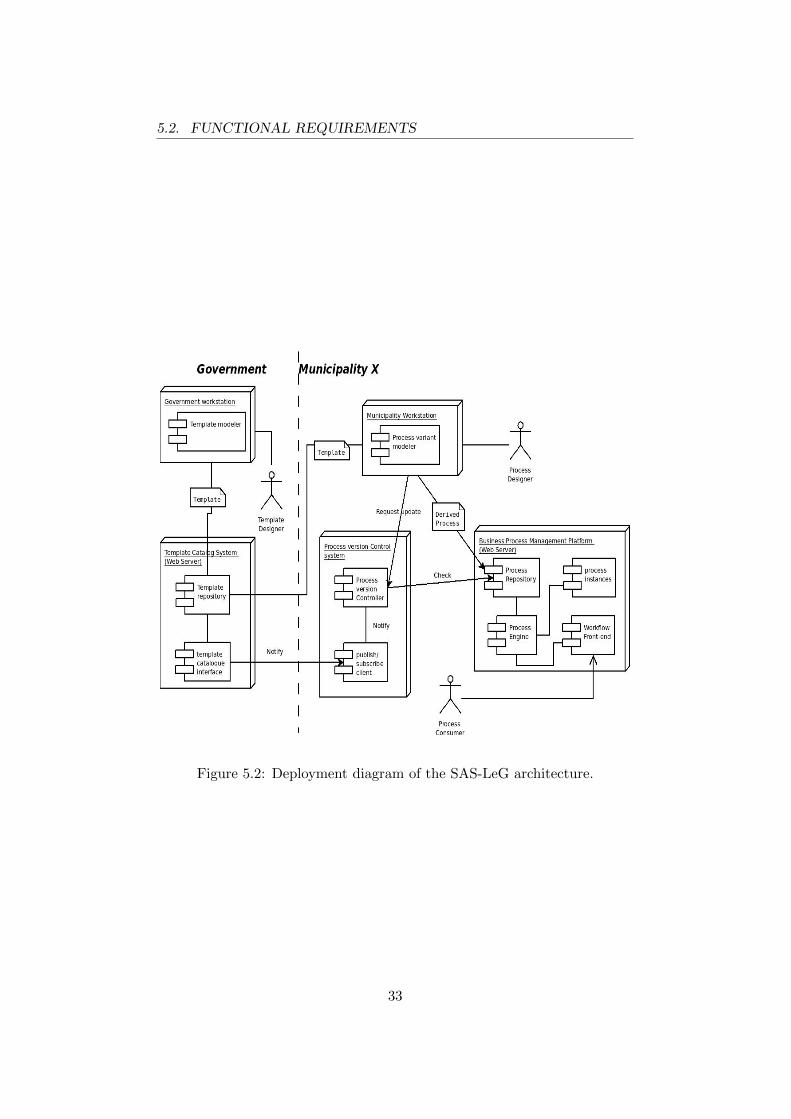
5.1.2 System Overview
The architecture is given as a (loosely) UML deployment diagram in Figure5.2. The diagram depicts how the process pipeline (see Section 5.1.1) iscarried out, with respect to the hardware and software components and theusers. The rectangle shapes with two smaller rectangles anchored on them,represent software components. The software components are placed insidenodes (box shapes). The nodes represent hardware systems or platforms
29

5.1. ARCHITECTURE WITHIN THE SAS-LEG CONTEXT
Figure 5.1: The process pipeline in e-Government.
30
5.1. ARCHITECTURE WITHIN THE SAS-LEG CONTEXT
on which software components are installed. A connection between com-ponents is represented by a line. Lines ending with an arrowhead, expressflow of information in a certain direction. The architecture is divided intwo sections, existing of components needed for the government and com-ponents needed for municipalities. The dashed line represents this division.The left area represents the government, whereas the area on the right rep-resents a SAS-LeG enabled municipality. A single municipality is labeledwith ”municipality X”, which means there is a one-to-many relation be-tween government and municipalities.
A variability supported process life cycle starts with the design of a processtemplate. Using a modeling tool, a template designer constructs a processtemplate from the corresponding law documents. After approval, templatesare stored in a template repository. Since templates need to be offered asreusable services to the municipalities, a catalog system is needed that hasaccess to the template repository. The template catalog has a publish/ sub-scribe interface that can be accessed by municipalities. For simplicity, boththe catalog interface and the template repository are drawn as componentshosted on a Web server. In reality, these components might be distributeddifferently.
Municipalities need process templates that are offered by the government.Publish/ subscribe software is required to let municipalities subscribe to theprocess templates of their needs. The publish/ subscribe client keeps trackon the internal version control of process models. After subscription to aparticular process, a municipality can receive a template from the templatecatalog when authorized. Once a process template has been modified duringits life cycle, the template catalog notifies each subscribed municipality ofa new version. The publish/ subscribe client software running at the mu-nicipality side forwards a notification to the version controller. The versioncontroller keeps track of the internal deployed processes and can check theinternal process repository of a municipality.
A process designer uses a process variant modeling tool in which templatescan be customized. The process variant modeling tool receives a list of up-dates from the ”process version controller”. A process designer makes thenecessary customizations and derives a process variant from the process tem-plate. The variant modeling tool is equipped with a model checker, whichverifies a customized process model against the specification of the respec-tive process template. After successful verification of a variant, the processvariant is ready to be sent to the process repository. The process repositoryof a municipality stores deployed process models that derived from processtemplates, and is within the back-end of a Business Process Management
31

5.2. FUNCTIONAL REQUIREMENTS
System (BPMS).
A BPMS is a platform that includes a wide variety of tools for BPM such asa process modeling tool, a process execution engine, process simulation toolsand process monitoring dashboards. A process execution engine creates andmaintains instances of a process model. Process instances are the actualrunning processes that are consumed by either human or machine commu-nication. Typically, processes are human centered where humans performpart of the work required within a particular process. Therefore, a richBPMS platform does have means for interaction with processes. Notifica-tions such as e-mail are sent to users when a certain state within the processis reached. A process might wait in a state for the user to reply and fill inthe data required via (Web) forms. The software for interaction is picturedin the diagram as the workflow front-end component.
A process consumer can be any type of user such as an employee, a citizen ora machine. Cordys has made their BPMS platform, Cordys BOP, availablefor the SAS-LeG project. Cordys BOP does have development tools inte-grated into the platform, including a process modeling tool. However, sinceCordys BOP and its integrated process modeling tool do not support vari-ability, an external tool is needed that does support variability. The nodelabeled with business process management platform is kept simple for thesake of understanding the diagram, though in reality the architecture hasmore detail and different components are distributed over multiple dedicatedsystems and may be inside a cloud.
5.2 Functional Requirements
Section 5.1 describes a simplified architecture of the SAS-LeG approach.Now that the rationale for the need of a tool is given in the context ofe-Government, the tool can be discussed. This section starts with a listof functional requirements for the prototype of the tool. The next twosubsections explain the functional requirements along two use case diagrams.The functional requirements of the tool are:
1. Designing a business process in a standardized form;2. Support for the following constraints:
(a) Mandatory/ optional activities;(b) Flow constraint;(c) Parallel constraint;(d) Frozen and semi-frozen group.
3. Saving templates;4. Open templates;5. A mode for switching between template and process design;
32
5.2. FUNCTIONAL REQUIREMENTS
Figure 5.2: Deployment diagram of the SAS-LeG architecture.
33

5.2. FUNCTIONAL REQUIREMENTS
6. Verification of process models;7. Comparing process models.
5.2.1 Use Case Diagram: System
The use case diagram in Figure 5.3 shows the desired behavior of the toolas being an integrated part of the SAS-LeG system. Only the use cases thatrelate to the tool, are shown in the diagram.
A template designer models a reference process as a BPMN diagram, whichrelates to the first requirement ”designing a business process in a standard-ized format”. The second requirement is ”support of constraints”, whichcorresponds to the use case ”model template”. BPMN diagrams can beconstrained by the constraint features of the PVDI framework. Approvedtemplates are submitted to a template repository. A process designer isable to receive a template from the repository and can then customize theprocess. When a process is customized, a process designer can give approvalfor deployment. Before deployment, consistency of the process is checkedagainst the template constraints (requirement 6). Whenever a customizedprocess model is inconsistent with a template, the tool should give an errorand flag the inconsistencies.
5.2.2 Use Case Diagram: Process Modeling Tool
The use case diagram depicted in Figure 5.4 shows the required behavioralaspects of the tool. This diagram makes no separation between templatedesigner and process designer. Both roles are now represented by the actor”process designer”. Separation of roles is left out, because both BPMNelements and constraint elements can be represented by the same abstractconcept of ”graphical element”. The same is true for connectors betweenelements.
The process designer creates a template on a canvas where the graphicalelements can be placed. A graphical element can be either a BPMN elementor a template element. After an element has been placed on the canvas, itcan be selected. A selected element can be removed or moved position overthe canvas. Furthermore the properties can be changed. The elements canbe connected by either a BPMN connector such as a flow or a constraintconnector such as a parallel constraint. Connectors also have properties thatcan be set by the user.
Some template constructs can only be applied on a selected element orconnector (use case ”assign constraint on selection”). Depending on therole of template designer or process designer, the tool should have a modewhere both roles can be carried out. Of course a process model can be
34

5.2. FUNCTIONAL REQUIREMENTS
Figure 5.3: Use case diagram: system.
35

5.3. DEVELOPMENT CHALLENGES
Figure 5.4: Use case diagram: process modeling tool.
imported and exported by the user. Finally, a customized process modelcan be checked on correctness.
5.3 Development Challenges
Because demonstrating the PVDI framework with a software tool is centralto this thesis, development of this tool comes with a few challenges. Thenext paragraphs describe the challenges that arose during development ofthe software prototype that is introduced in Chapter 6. These challengesare typical for development of a graphical modeling tool.
Software Design and Development
The first challenges are software design and development. Even thoughthe tool is a prototype, software design is important because a graphical
36

5.3. DEVELOPMENT CHALLENGES
modeling tool is a complex piece of software. As more features are re-quired, complexity increases significantly. A simple design serves as a roadmap during development. However, with increasing complexity, maintainingcomprehensiveness of the software design is difficult. The implementationpushes complexity further. During programming, many unforeseen imple-mentation specific issues arise. Those details add up to the challenges ofa software project. Additionally, software design has challenges on its ownand requires application of varying software engineering disciplines such assoftware patterns, architecture and software design.
2D Graphics and Interaction
Since BPMN models are 2-dimensional diagrams, 2D graphics is essentialfor a graphical modeling tool. A wide variety of 2D graphics libraries areavailable for most programming languages. Each graphics library has itspros and cons. Some libraries are easy to use, but do not support advancedgraphical operations. Other libraries are low-level and require more geom-etry and programming skills from the programmer. Basic knowledge of 2Dgraphics is required in any case. When a particular graphical feature missingin a graphics library, geometry is needed for a self-made implementation.
Marshaling
A graphical editor needs the ability to import and export process models,which is usually done using the Extensible Markup Language (XML). Whenprocess models are stored and later retrieved, the visualization should ex-actly be as before. Preferably, the format should be compatible with otherexisting business process modeling tools. The graphical editor needs a mar-shaling component for storing and retrieving business process diagrams inan XML based language that is able to capture graphical and executableaspects. Furthermore, the XML format to be used requires a modification,such that template functionality can be stored.
Model Checking
Customized process models need to be checked whether they are valid deriva-tions of a process template. A template can virtually have an infinite amountof customized process variants. Permutation of different process graphs, de-pends entirely on the constraints in a process model, and because of theproperty of endless ways in configuring graphs, the PVDI framework pro-poses formulas for each constraint. Thus, the tool requires to have a modelchecker, that implements the PVDI framework. Model checking involvesgraph theory and temporal logic.
37

5.4. IMPLEMENTATION
5.4 Implementation
The tool presented in this thesis (see Chapter 6), is a prototype for demon-strating and testing practicability of the PVDI framework. Groefsema, etal. [14] developed a Java package for offering tool support of the PVDIframework. The core of the package is a CTL+ model checker in which aprogrammer can create CTL+ formulas. The tool is developed from scratchand is kept simple to demonstrate the purpose of the SAS-LeG approach tobusiness process variability. The tool uses the PVDI package to generateand verify CTL+ formulas from a given process template.
Since only a Java Runtime Environment is required, the tool can be easilydistributed for testing purposes. A testing user is not burdened with instal-lation of any proprietary software, or software development environmentssuch as the Eclipse platform. In addition, carrying out new ideas is easier,and does not put restrictions on development. A major drawback of thisapproach is that a lot of effort in development is required, which burdenedthis thesis with a lot of implementation specific details.
Because most tool vendors support XPDL (see Section 3.1.3) as format forinterchanging process models, selecting XPDL was an easy choice. More-over, Cordys BOP process modeler [6] has XPDL support for importing/exporting process models. Because Cordys is a technology partner of theSAS-LeG project and the ability to extend XPDL with new constructs fortemplate constraints, using XPDL for storing process templates was a con-venient choice. The Cordys BOP platform contains a plethora of BPM toolsincluding a process execution engine. The software prototype can be usedin conjunction with Cordys BOP, to simulate a process life cycle.
38

Chapter 6
Software Prototype
The PVDI framework (see Chapter 4) proposes process templates, in whicha combination of declarative and imperative modeling techniques are usedfor describing variability in process models. Process templates are con-structed from a reference process and a set of constraints. The constraintsdescribe variability in business process models. The PVDI framework pro-vides a formalization of how constraints on a process model can be checked.BPMN (see Section 3.1.2) is the process language used for modeling processdiagrams. The formalization of constraints is given in CTL+, which de-scribes how model checking can be done for template compatible modelingtools. This chapter introduces the Variability extended BPMN (VxBPMN)designer, which demonstrates the PVDI framework in practice. Each con-straint from the PVDI framework specified in [14] is showcased in Section6.2.
6.1 VxBPMN Designer
VxBPMN designer (see Figure 6.1) is a graphical modeling tool, running asa Java stand-alone application. VxBPMN designer runs on any computerequipped with a Java Runtime Environment and can be easily distributed.The Graphical User Interface (GUI) has the standard Java Swing look andfeel.
The canvas located at the center, is where business process diagrams aredrawn. The toolbox located on the left, is where the constructs for a tem-plate/ process can be selected from. A selected element or connector can beput on the canvas. VxBPMN designer can be in either two modes, ”tem-plate design” or ”process design”. These modes reflect the role of the user.In ”template design”, the toolbox is equipped with the constraints featuresin addition to the BPMN constructs. The buttons for adding constraintsare not available in ”process design”. In ”template design”, the user has full
39

6.1. VXBPMN DESIGNER
Figure 6.1: VxBPMN designer.
control over editing the BPD, whereas in ”process mode” the user can onlychange what is allowed according to the template. The mode, the user isworking in, is showed in the status bar at the bottom of the GUI.
Figure 6.1 also shows an example of a simple process model with four ac-tivities, one gateway and a start and end event of the process. Elementsare labeled and connected by flows (visualized as arrows). Process modelscan be checked whether they are valid according to their templates. Whena process model contains errors, the graphical elements on the canvas arehighlighted. The highlighted errors are explained with textual descriptions,summarized in the ”check results” tab located at the bottom region of theGUI. A description and the corresponding resource responsible for the error,are given. Furthermore, VxBPMN designer comes with tool and menu barslocated at the top of the GUI, where most functionality is found.
40
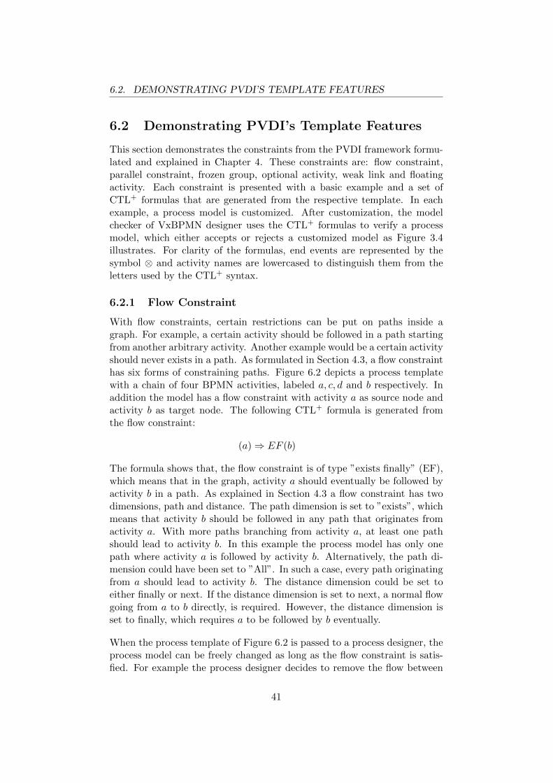
6.2. DEMONSTRATING PVDI’S TEMPLATE FEATURES
6.2 Demonstrating PVDI’s Template Features
This section demonstrates the constraints from the PVDI framework formu-lated and explained in Chapter 4. These constraints are: flow constraint,parallel constraint, frozen group, optional activity, weak link and floatingactivity. Each constraint is presented with a basic example and a set ofCTL+ formulas that are generated from the respective template. In eachexample, a process model is customized. After customization, the modelchecker of VxBPMN designer uses the CTL+ formulas to verify a processmodel, which either accepts or rejects a customized model as Figure 3.4illustrates. For clarity of the formulas, end events are represented by thesymbol ⊗ and activity names are lowercased to distinguish them from theletters used by the CTL+ syntax.
6.2.1 Flow Constraint
With flow constraints, certain restrictions can be put on paths inside agraph. For example, a certain activity should be followed in a path startingfrom another arbitrary activity. Another example would be a certain activityshould never exists in a path. As formulated in Section 4.3, a flow constrainthas six forms of constraining paths. Figure 6.2 depicts a process templatewith a chain of four BPMN activities, labeled a, c, d and b respectively. Inaddition the model has a flow constraint with activity a as source node andactivity b as target node. The following CTL+ formula is generated fromthe flow constraint:
(a)⇒ EF (b)
The formula shows that, the flow constraint is of type ”exists finally” (EF),which means that in the graph, activity a should eventually be followed byactivity b in a path. As explained in Section 4.3 a flow constraint has twodimensions, path and distance. The path dimension is set to ”exists”, whichmeans that activity b should be followed in any path that originates fromactivity a. With more paths branching from activity a, at least one pathshould lead to activity b. In this example the process model has only onepath where activity a is followed by activity b. Alternatively, the path di-mension could have been set to ”All”. In such a case, every path originatingfrom a should lead to activity b. The distance dimension could be set toeither finally or next. If the distance dimension is set to next, a normal flowgoing from a to b directly, is required. However, the distance dimension isset to finally, which requires a to be followed by b eventually.
When the process template of Figure 6.2 is passed to a process designer, theprocess model can be freely changed as long as the flow constraint is satis-fied. For example the process designer decides to remove the flow between
41

6.2. DEMONSTRATING PVDI’S TEMPLATE FEATURES
Figure 6.2: Flow constraint between activities a and b.
activity d and b. The modified process model is shown in Figure 6.3. Sincethe process model has no path leading to activity b, the model checker givesan error. The process designer should satisfy the flow constraint, else themodel checker gives an errors. The flow constraint guarantees that activityb will always be followed somewhere in any path originating from activitya. In a simple graph, the advantage might not look obvious. However, forlarge process models with multiple branching paths having chains consist-ing of large number of activities, the flow constraint would be very useful.VxBPMN designer helps the user in not forgetting to satisfy this require-ment. Theoretically, flow constraints can handle connected structures withan infinite number of elements. Eventually, regardless the length of a chain,a should be followed by b.
42

6.2. DEMONSTRATING PVDI’S TEMPLATE FEATURES
Figure 6.3: Flow constraint not satisfied.
43

6.2. DEMONSTRATING PVDI’S TEMPLATE FEATURES
6.2.2 Parallel Constraint
As explained in Section 4.4, a parallel constraint between two activities,enforces that any flow coming out of any of the two shall never finally leadinto the other activity. Either activity always exclude their outgoing flowsequence leading into the other one. Figure 6.4 and 6.5 demonstrate theparallel constraint. The shape for a parallel constraint is a dashed line witha diamond shape on both ends of the line as illustrated in Figure 4.2. InFigure 6.4, a parallel constraint is drawn between activity a and activity b.The following CTL+ formulas are generated for the parallel constraint:
(a)⇒ AG¬(b)
(b)⇒ AG¬(a)
As the figure illustrates, no sequence of flows starts from activity a andends in activity b, nor has the graph a sequence starting from b ending ina. Both activities mutually exclude each other from passing information to,or receiving information from each other in any path. During verificationof the process model, VxBPMN designer does not report an error, becauseboth activities are parallel from each other.
In Figure 6.5, an error is flagged when the model is checked. The corre-sponding parallel constraint is now colored red, which means that the paral-lel constraint is not satisfied. Additionally, an error message is given in the”check results” table. The error message: ”a may never be in the same pathas b” indicates the presence of a flow sequence starting from activity a thatends in activity b eventually. The constraint is not satisfied because of a flowsequence leading from activity c to activity b labeled ”flow 1” that violatesthe parallel constraint. Because activity c can be reached from activity a,the process model has a sequence flow from activity a to activity b, makingthe model invalid. The model checker makes sure that an activity is neverin the same path as the other activity, regardless of the process’ complexity.
A parallel constraint is useful when one wants to enforce that both activitiesare always parallel to each other. In this example, the violation can easilybe seen, but when process models increase in complexity, manually checkingerrors becomes difficult. A model checker is responsible for verifying thata constraint is never violated, regardless a graph’s complexity. The CTL+
formulas behind the scenes, make sure that a constraint should always besatisfied. Furthermore, like the flow constraint, a parallel constraint workson a set of activities.
6.2.3 Frozen Group
Section 4.5.1 presented the frozen group along with the CTL+ formulasneeded for model checking. This section demonstrates the frozen group
44

6.2. DEMONSTRATING PVDI’S TEMPLATE FEATURES
Figure 6.4: Parallel constraint between activities a and b.
45

6.2. DEMONSTRATING PVDI’S TEMPLATE FEATURES
Figure 6.5: Parallel constraint violated.
46

6.2. DEMONSTRATING PVDI’S TEMPLATE FEATURES
constraint as a template feature of VxBPMN designer. Figure 6.6 depicts asimple process model that is entirely enclosed by a frozen group. The frozengroup is visualized as a dashed rounded rectangle. From the perspective ofthe user interface, the frozen group works like a compartment, which is aregion in which other elements can be placed. All elements inside the regionof a frozen group, belong to it. The user can either put a frozen group arounda region of elements, or elements can be put inside an already existing frozengroup. The formula generator of the tool creates the following formulas fromthe template.
a⇒ A[((b ∨ c ∨ d)U⊗) ∨ ((b ∨ e ∨ f)U⊗)]
b⇒ A[((c ∨ d)U⊗) ∨ ((e ∨ f)U⊗)]
c⇒ A(dU⊗)
d⇒ AX ⊗e⇒ A(fU⊗)
f ⇒ AX⊗
As explained in Section 4.5.1, a process designer is not allowed to makeany modifications to a graph that is inside a frozen group. When a processdesigner tries to modify a frozen group, the model checker raises an errorduring verification. In Figure 6.7, activity g is added to the frozen group.The model checker flags an error by highlighting the structure where theerror occurs, and provides an error message in the ”check results” table.Activities a and b and the start event, are also highlighted because activityg is reached via those three elements. Preferable, activity g should havebeen highlighted as the element that causes the error (not implemented inthis prototype).
A frozen group is threated as a sub process with an implicit start and endevent. For simplicity, groups cannot be nested in the version of the toolpresented in this thesis, and only supports groups with one start and oneend event. The implicit start and end events are necessary because themodel checker needs to create formulas for each path between start andend nodes. The inclusion of start and end events are used to simplify pathsearching. With an implicit inclusion of a start and end event, the formulagenerator only needs to find all paths in between, whereas if they are notpresent, the search for start and end events would have been required.
6.2.4 Optional Activities
Since generating CTL+ formulas and model checking are computational in-tensive, generating CTL+ formulas for a frozen group might seem unneces-sary, because the user could as well be restricted from editing a frozen group.However, a frozen group can be made semi-frozen. A group constraint leaves
47

6.2. DEMONSTRATING PVDI’S TEMPLATE FEATURES
Figure 6.6: Frozen group.
48

6.2. DEMONSTRATING PVDI’S TEMPLATE FEATURES
Figure 6.7: Frozen group violated by activity g.
49

6.2. DEMONSTRATING PVDI’S TEMPLATE FEATURES
Figure 6.8: Activity b is optional.
room for modifications, which needs to be explicitly specified, as the frozengroup does not allow any modifications by default. The first semi-frozenfeature is the ”optional activity”. As explained in Section 4.5.2, optionalactivities are allowed to be removed from the frozen group. In contrast tooptional activities, ”mandatory activities” are not allowed to be removed.Figure 6.8 depicts a semi-frozen group with activity b made optional. Op-tional activities are visualized with a single border; mandatory activitieshave a double border. When activity b is removed from the process model,the graph looks like Figure 6.9. Because activity b is optional, the modelchecker does not raise an error. Hence, the resulting process model in Figure6.9 is a valid derivation from Figure 6.8.
6.2.5 Weak Link
Another feature of the semi-frozen group is the weak link. A weak link al-lows for arbitrary insertion of multiple paths of nodes between the source
50

6.2. DEMONSTRATING PVDI’S TEMPLATE FEATURES
Figure 6.9: Optional activity b removed.
51

6.2. DEMONSTRATING PVDI’S TEMPLATE FEATURES
and target nodes of a weak link. A weak link is similar to a flow constraintwith a ”exist finally” property. The graph of Figure 6.6, from the frozengroup example given in Section 6.2.3, is modified to illustrate the weak linkfeature. Any BPMN flow between two activities can be weakened. A linkcan be weakened by right clicking a BPMN flow inside a frozen group andselect ”weaken” from the context menu.
When a flow is weakened, the frozen group becomes semi-frozen. A templatewith a weak link is shown in Figure 6.10. A weak link is represented as aflow with a dashed line. In this example a template designer has weakenedthe link between activity a and b, labeled ”Weaken 1”, and has a secondweak link between activity e and f , labeled ”Weaken 2”. The inverse oper-ation strengthens a weak link back to a normal BPMN flow connector. Thefollowing CTL+ formulas are generated.
a⇒ AFA[((b ∨ c ∨ d)U⊗) ∨ ((b ∨ e)UAF (fU⊗))]
b⇒ A[((c ∨ d)U⊗) ∨ ((e)UAF (fU⊗))]
c⇒ A(dU⊗)
d⇒ AX ⊗e⇒ AFA(fU⊗)
f ⇒ AX⊗
When the template of Figure 6.10 is passed to a municipality, a processdesigner is free to add, an element between activity a and activity b as theflow between those two activities, is a weak link. In Figure 6.11, a processdesigner has added activity ab between those two activities. The addition ofactivities would be correctly verified by the model checker as the weak linkallows the insertion of activity ab between its source and target nodes.
A weak link also allows a whole chain of connected elements to be insertedbetween its source and target nodes. Activities g, h, i and j are a chainof connected activities and placed between the source and target nodes of”weaken 2”. In this example four elements are placed in between withtwo paths; However, theoretically an unlimited number of activities can beadded. The process model is correctly verified, and the model checker doesnot give an error. If an activity is placed between the source and target nodesof a normal flow, say an activity between activity c and d, then the modelchecker gives an error; Hence, the flow between c and d is not weakened.
6.2.6 Floating Activities
A third semi-frozen feature is the floating activity. A floating activity can bemoved inside a frozen group, making it possible to change position inside agraph. The premise is, that floating activities can only be moved to positions
52
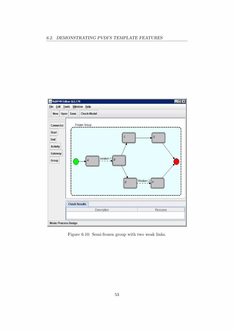
6.2. DEMONSTRATING PVDI’S TEMPLATE FEATURES
Figure 6.10: Semi-frozen group with two weak links.
53

6.2. DEMONSTRATING PVDI’S TEMPLATE FEATURES
Figure 6.11: Weak link allows insertion of activities.
54
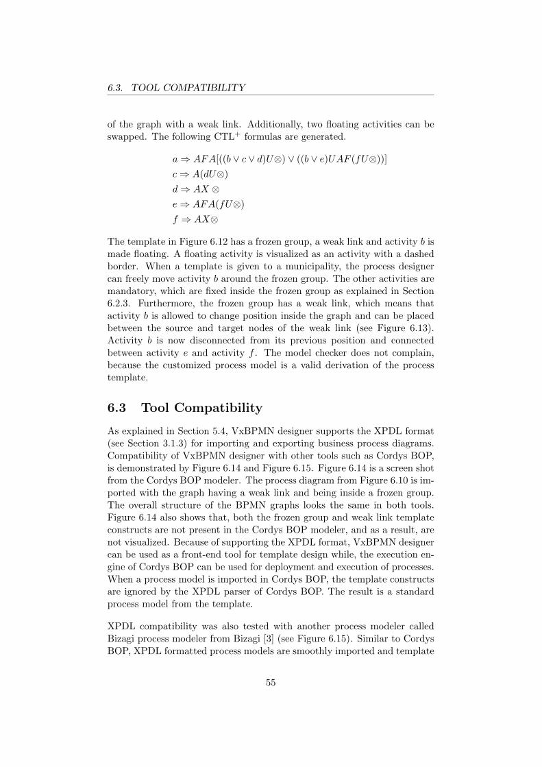
6.3. TOOL COMPATIBILITY
of the graph with a weak link. Additionally, two floating activities can beswapped. The following CTL+ formulas are generated.
a⇒ AFA[((b ∨ c ∨ d)U⊗) ∨ ((b ∨ e)UAF (fU⊗))]
c⇒ A(dU⊗)
d⇒ AX ⊗e⇒ AFA(fU⊗)
f ⇒ AX⊗
The template in Figure 6.12 has a frozen group, a weak link and activity b ismade floating. A floating activity is visualized as an activity with a dashedborder. When a template is given to a municipality, the process designercan freely move activity b around the frozen group. The other activities aremandatory, which are fixed inside the frozen group as explained in Section6.2.3. Furthermore, the frozen group has a weak link, which means thatactivity b is allowed to change position inside the graph and can be placedbetween the source and target nodes of the weak link (see Figure 6.13).Activity b is now disconnected from its previous position and connectedbetween activity e and activity f . The model checker does not complain,because the customized process model is a valid derivation of the processtemplate.
6.3 Tool Compatibility
As explained in Section 5.4, VxBPMN designer supports the XPDL format(see Section 3.1.3) for importing and exporting business process diagrams.Compatibility of VxBPMN designer with other tools such as Cordys BOP,is demonstrated by Figure 6.14 and Figure 6.15. Figure 6.14 is a screen shotfrom the Cordys BOP modeler. The process diagram from Figure 6.10 is im-ported with the graph having a weak link and being inside a frozen group.The overall structure of the BPMN graphs looks the same in both tools.Figure 6.14 also shows that, both the frozen group and weak link templateconstructs are not present in the Cordys BOP modeler, and as a result, arenot visualized. Because of supporting the XPDL format, VxBPMN designercan be used as a front-end tool for template design while, the execution en-gine of Cordys BOP can be used for deployment and execution of processes.When a process model is imported in Cordys BOP, the template constructsare ignored by the XPDL parser of Cordys BOP. The result is a standardprocess model from the template.
XPDL compatibility was also tested with another process modeler calledBizagi process modeler from Bizagi [3] (see Figure 6.15). Similar to CordysBOP, XPDL formatted process models are smoothly imported and template
55

6.3. TOOL COMPATIBILITY
Figure 6.12: Activity b is floating.
56

6.3. TOOL COMPATIBILITY
Figure 6.13: Floating activity b can be moved.
57

6.3. TOOL COMPATIBILITY
Figure 6.14: Imported process model in Cordys BOP.
constructs are ignored by the Bizagi process modeler. Furthermore, all threemodeling tools: VxBPMN designer, Cordys BOP modeler and the Bizagimodeler visualize a process model slightly different (see Figure 6.10, Fig-ure 6.14 and Figure 6.15). The differences are minor in appearance and theBPMN structure remains the same in all three modeling tools. For example,the flows in the Bizagi modeler have rounded edges whereas both VxBPMNdesigner and Cordys BOP modeler use sharp edges. Different tools havedifferent ways of how the graph should exactly be visualized. These typeof graphical preferences can be marshaled in XPDL, which are not forcedand any XPDL supporting tool, might choose its own form for the exactlayout. These layout differences such as edge visualization and color prefer-ences are tool specific. Nevertheless, the structure of a graph remains thesame. Another feature of XPDL, is the option for storing tool and vendorspecific properties, allowing different tool developers to have their tool spe-cific preferences stored in the XPDL file. Lastly, process models designedwith other tools such as Cordys BOP modeler or Bizagi process modeler,can be imported by VxBPMN designer as well.
58

6.3. TOOL COMPATIBILITY
Figure 6.15: Imported process model in Bizagi process modeler.
59
Chapter 7
Conclusions
From the main research question stated in Section 1.3, three sub questionswere derived. The sub questions are:
1. How would process variability using the PVDI frameworkchange the standard life cycle of business process management?
The SAS-LeG project proposes Software as a Service as a model for reusableIT components in e-Government systems. Chapter 2 issues the need for aspecific type of business process variability. This specific type of variabilityseparates two organizational roles of authority concerning design of processmodels. A scenario describing the need for process variability is given inSection 2.2 and Section 3.3 explains business process variability.
The PVDI framework described in Chapter 4 proposes a declarative ap-proach for modeling process variability combined with an imperative processdesign language such as BPMN (see Section 3.1.2). Declarative approachesconstrain process models while providing flexibility for customization fea-tures. Business process management is explained in Section 3.1.4 alongwith its life cycle. However, current BPM practices do not incorporate pro-cess variability, and as a result business process platforms such as CordysBOP are not ready yet for design and management of process variability.Variability management and the PVDI method specifically introduces an-other phase in the life cycle of BPM. For certain type of organizations suchas e-Governments, this phase is required to implement a process as much aspossible once, yet providing a degree of flexibility for customization. In Sec-tion 5.1.1 the process pipeline conceptually illustrates how the introductionof the method proposed by the PVDI framework would change the BPMlife cycle. Furthermore, a simplified system architecture is given in Section5.1.2 with respect to the addition of the PVDI framework in business pro-
60

cess management.
2. What is needed to achieve compatibility with other processtools, such that the business process life cycle incorporating thePVDI method can be simulated?
VxBPMN designer supports import and export of process models in XPDLformat. Support of XPDL, makes VxBPMN designer compatible with var-ious (BPMN supported) process modeling tools. Section 6.3 shows thatthe structure and overall graphical layout of process models designed inVxBPMN designer, are preserved when imported in other XPDL supportedmodeling tools such as Cordys BOP designer and Bizagi process modeler.XPDL’s extensions ability was also demonstrated, by adding tags for stor-ing template specific data such as flow and group constraints. Tools withno support for PVDI templates, can still import the reference process froma process template. Both, Cordys BOP designer and Bizagi process mod-eler ignore tags that yield template information when importing XPDL files.Whenever a process template is imported in a non-PVDI supported processmodeler, the process model is visualized such that only the core structureof the reference process model remains. The remaining process model thenrepresents the standard/ advised process model of a template.
Furthermore, VxBPMN designer has a function for switching modes thatrepresent the roles of template design and process customization. In tem-plate mode, the user is able to constrain a process model, whereas in processmode the user can only use BPMN elements for customization. The CTL+
formulas are generated directly after a template is imported in process mode.Any time during customization, process models can be checked. The modelchecker uses the CTL+ formulas as a specification to verify customized pro-cess models, and checks whether any constraint is violated.
3. Does an automated model checker confirms formal verificationof the PVDI framework on customized process models?
The PVDI framework extends BPMN with template semantics for designingprocess families. The PVDI framework comes with algorithms for generatingCTL+ formulas. These formulas are input for model checking. VxBPMNdesigner is a software prototype that implements the PVDI framework andis equipped with a formula generator and a model checker. Model checkingis required for deriving valid process models from a process template aftera model is customized. Whenever verification of a process model fails, thetool provides both textual and graphical feedback. The template featuresare: flow constraint, parallel constraint, frozen group and semi-frozen group.The constraints are demonstrated in Section 6.2 by providing both correct
61

and incorrect process models to the model checker of VxBPMN designer.Each demonstrated constraint confirms its specification formulated in [14].
The main research question of this thesis is:
Would a software prototype, demonstrate the PVDI framework asa candidate solution for modeling explicit variability in businessprocess models?
The objective of this thesis is to introduce a process modeling tool that im-plements and demonstrates the PVDI framework practically. The softwareprototype is successfully implemented, meeting a minimum set of functionalrequirements listed in Section 5.2. With this software prototype, basic pro-cess diagrams are drawn with a subset of the business process modelinglanguage BPMN.
The process pipeline (see Section 5.1.1) conceptually illustrates how thePVDI framework changes the BPM life cycle. A full simulation of the pro-cess pipeline can be achieved by having a process execution engine as back-end tool and a process template modeling tool as a front-end. A businessprocess platform such as Cordys BOP is used as execution engine, whichuses BPMN as a design language for process modeling, and XPDL as aninterchange format for storing graphical process models. VxBPMN designeris used to demonstrate template design and customization. A demonstra-tion of the software prototype in Section 6.2 confirms practical working ofthe constraints from the PVDI framework (see Section 4).
In conclusion, VxBPMN designer demonstrates practical feasibility of thePVDI framework as a specification language for constraining process mod-els as templates. The constraints are translated to CTL+ formulas thatform the specification for process models for the automated model checkerof VxBPMN designer. A model checker verifies whether customized processmodels are valid variants of a process family according its specification. Amodel checker aids during customization of process variants that are validmembers of a process family defined by its process template. AlthoughVxBPMN designer is in an incipient state, the tool demonstrates that thePVDI framework makes a good case of balancing preservation of structurewhile providing flexibility for customization. The amount of flexibility andpreservation of structure depend on how a specific set of constraints restricta template contained process model.
62

7.1. FUTURE WORK
7.1 Future Work
Because this work involved development of a prototype tool, future work isdivided in research topics and development effort.
7.1.1 Research Opportunities
The following paragraphs present topics that relate to the tool presented inthis thesis.
Usability of the PVDI Language
Because business process management is an interdisciplinary subject [20],there are opportunities in multiple different fields of research. Topics likeusability, visual perception, and languages are abundantly studied in varioussciences. A visual language such as VxBPMN might still fail when it is hardto learn or when graphical elements are confusing. Thus, a combinationof those different aspects influence the success and applicability of the pro-posed method. These aspects are: expressiveness of a language, usabilityand possibilities of both the modeling language and tools supporting thelanguage. Interaction and automation possibilities. Various studies such asin [12] apply knowledge from other scientific disciplines for developing vi-sual languages used for domain modeling such as business process modeling.Much of the theory comes from psychology.
Visual and Semantic Discrepancy
The set of graphical elements from the PVDI framework should not vio-late with the BPMN specification. Furthermore elements from the PVDIframework should not cause confusion with elements from BPMN. Elementsshould be discriminative and the graphical notation for each feature shouldreflect its semantics. How visual symbols are perceived by humans goes be-yond the realm of computing and is about psychology and linguistics. Fromother sciences such as psychology, best practices for enhancing the graph-ical notation of the PVDI framework can be found in literature of thoserespective sciences and interdisciplinary research fields.
BPMN Specific or Process Modeling Language Generic?
A major question is, whether PVDI should be a separate notation and frame-work, independent of the process language to use or should it be specific toBPMN? If PVDI is restricted to BPMN only, can PVDI become part of theBPMN specification in a future version of BPMN, or should BPMN andPVDI remain separate notations, where PVDI can be used as an extension.
63

7.1. FUTURE WORK
If PVDI needs to support multiple process modeling languages then thequestion is: how can PVDI be generalized, to support those languages?
Interoperability of PVDI
From the previous issue, one can raise the question: how should the PVDIframework be formalized as a machine readable format? The constraintsare currently put in a modified XPDL schema. Since the additions to theschema, are committed by other XPDL compatible tools, standardization isrequired for other tools to adopt the PVDI framework. Does XPDL need anupdate with template semantics of the PVDI framework? Do other machinereadable process formats prove better integrability of the PVDI frameworkor does the PVDI framework needs to have its own XML schema?
Improving Template Expressiveness
Interesting would be, whether the PVDI framework can be combined withother variability techniques to provide more flexibility and constraint fea-tures. One such technique would be the use of questionnaires such as in[23]. Where questions are created by the template designer and the answerscan be filled in by the process designer. Such late modeling techniques areuseful when a template designer wants to force the process designer to fillin an answer.
Domain Applicability
Furthermore, would BPMN remain a professional tool for the business indus-try and will the users remain business analysts? Alternatively, can BPMNcombined with PVDI become a visual programming language for other do-mains? Does PVDI have use for other type of processes, e.g., as proposedin [9] where a process of giving a party is used as example for processes insmart homes as services in luxury or aiding disabled people.
Automation
Finally, could the design of process models/ templates be further auto-mated? Ultimately, the vision of the SAS-LeG project is that the lawdescribed in natural language, instantly adapts to each municipality with-out human intervention. When the law changes, the processes used at themunicipalities should change accordingly. Future research is needed to seewhether natural language processing can be applied, in which law writtenin natural language is automatically transformed in a process template, inwhich the law is digitally conserved.
64

7.1. FUTURE WORK
7.1.2 Tool Improvements
The following paragraphs present possible improvements of the tool pre-sented in this thesis.
BPMN Validation
Although VxPBMN designer verifies process templates, the correctness ofBPMN models is not checked. Of course both should be checked before aprocess model should be deployed. However, as demonstrated in Section6.3, since the tool uses XPDL as a machine readable format for interchang-ing process models, a process model designed in VxBPMN designer can beimported by other BPMN modelers, which in turn can be used to checkwhether a process model is a valid BPMN graph. In contrary, a templatedoes not need to be valid BPMN, nor does a constraint need to be valid asa template is a mere blueprint for process models to be derived from thereference model contained by a template. Thus, in template mode, verifica-tion of the constraints and checking BPMN are not necessary. However, inprocess mode both are needed before a process should be deployed.
Basic Tool Operations
A basic feature missing, is to undo actions in the process design mode.Modifications done in process design mode like removing optional activitiescannot be undone or put back in a later stage. Other constraints sufferthe same problem. The include and exclude constraints also require a wayto put in certain elements like including or excluding activities. Thus, thetool needs to store all defined process elements templates are opened inprocess mode. The user should be able to easily put back template definedstructures. The tool needs another toolbox in process mode, consisting of theset of template actions. The defined BPMN elements, created in templatemode together with the constraints, determine the outcome space of possibleprocess variants.
Process Attachments
The previous issue gives birth to another usable feature for template design.Certain template defined structures might be allowable in a process variant,but might not be inside the reference process itself. For example the tem-plate process has a variation point where only one activity can be positioned,though the template designer wants to restrict the possible choices from aset of predefined fixed activities. In process mode, a mechanism shouldforce the process designer to make a choice from the possible options. Thisidea can be extended to stimulate reuse, where a template designer, can add
65

7.1. FUTURE WORK
”attachments” to a template. Attachments are predefined structures like ac-tivities filled in with a Web service for example. Those attachments are notin the reference processes itself, but are within the template of the process.Attachments are atomic building blocks that are allowable customizationsfor the realization of a derived process model. Without predefined atomiccompositions, a graph remains abstract and can be a structure for any typeof process. When activities are filled in, they capture part of the semantics.
Usability Testing
Lastly, thorough testing is needed to evaluate practical use of process tem-plates using the PVDI framework. Different types of data need to be ac-quired, especially those related to usability. Data acquired from usabilitytesting can be used to improve the PVDI framework and tool support, oreven open new opportunities. If users are satisfied using the tool, then PVDIhas a chance as a standard for process templates. Large amounts of dataabout user satisfaction is needed to see whether the PVDI framework addsvalue to BPM practices.
66

Bibliography
[1] Marco Aiello, Pavel Bulanov, and Heerko Groefsema. Requirements andTools for Variability Management. In COMPSAC Workshops, pages245–250. IEEE Computer Society, 2010.
[2] Alessandro Artale. Formal Methods. Computation Tree Logic (Lectureslides: Free University of Bolzano).
[3] Bizagi. Bizagi Process Modeler. Web site. http://www.bizagi.com.
[4] Chang-ai Sun and Marco Aiello. Towards Variable Service Compo-sitions Using VxBPEL. In Hong Mei, editor, ICSR, volume 5030 ofLecture Notes in Computer Science, pages 257–261. Springer, 2008.
[5] Workflow Management Coalition. XML Process Definition Language(XPDL). Web site. http://www.wfmc.org/xpdl.html.
[6] Cordys. Cordys Business Operations Platform Process Modeler. Website. http://www.cordys.com.
[7] Peter Dadam and Manfred Reichert. The ADEPT project: a decadeof research and development for robust and flexible process support.Computer Science - R&D, 23(2):81–97, 2009.
[8] T.H. Davenport. Process Innovation: Reengineering work through in-formation technology. Boston, 1993.
[9] Piet den Dulk. Managing variability in BPEL for adaptable domoticprocesses. Term project. University of Groningen, 2009.
[10] E.A. Emerson and E.M. Clarke. Using Branching-Time Temporal Logicto Synthesize Synchronization Skeletons. Science of Computer Pro-gramming, 2:241–266, 1982.
[11] E.A. Emerson and J.Y. Halpern. Decision Procedures and Expressive-ness in the Temporal Logic of Branching Time. Journal of Computerand System Science, 30:1–24, 1985.
67

BIBLIOGRAPHY
[12] Kathrin Figl, Michael Derntl, Manuel Caeiro Rodrıguez, and Luca Bot-turi. Cognitive effectiveness of visual instructional design languages. J.Vis. Lang. Comput, 21(6):359–373, 2010.
[13] Gautam Ray and Jay B. Barney and Waleed A. Muhanna. Capabilities,business processes, and competitive advantage: choosing the dependentvariable in empirical tests of the resource-based view. Strategic Man-agement Journal, 25:23–37, 2004.
[14] Heerko Groefsema, Pavel Bulanov, and Marco Aiello. Declarative En-hancement Framework for Business Processes. In Gerti Kappel, ZakariaMaamar, and Hamid R. Motahari-Nezhad, editors, ICSOC, volume7084 of Lecture Notes in Computer Science, pages 495–504. Springer,2011.
[15] Object Management Group. Business Process Model and Notation(BPMN) specification. 2008.
[16] M. Hammer and J. Champy. Reengineering the Corporation, A Mani-festo for Business Revolution. New York: HarperBusiness, 1993, 1993.
[17] Intalio. Intalio BPMS. Web site. http://www.intalio.com.
[18] Jan Johannsen and Martin Lange. CTL+ Is Complete for Double Ex-ponential Time. In Jos C. M. Baeten, Jan Karel Lenstra, JoachimParrow, and Gerhard J. Woeginger, editors, ICALP, volume 2719 ofLecture Notes in Computer Science, pages 767–775. Springer, 2003.
[19] Ekkart Kindler. On the semantics of EPCs: Resolving the vicious circle.Data Knowl. Eng., 56(1):23–40, 2006.
[20] Ryan K. L. Ko. A computer scientist’s introductory guide to businessprocess management (BPM). ACM Crossroads, 15(4), 2009.
[21] Tobias Kuster and Axel Heßler. Towards Transformations from BPMNto Heterogeneous Systems. In Danilo Ardagna, Massimo Mecella, andJian Yang, editors, Business Process Management Workshops, vol-ume 17 of Lecture Notes in Business Information Processing, pages200–211. Springer, 2008.
[22] Bram Leemburg. A declarative meta modeling approach to define pro-cess migration constraints. Master’s thesis, University of Groningen,2011.
[23] Vanessa Lopez, Enrico Motta, Victoria Uren, and Marta Sabou. Stateof the Art on Semantic Question Answering. Technical Report kmi-07-03, Knowledge Media Institute, Open University, Milton Keynes, UK,May 2007.
68

BIBLIOGRAPHY
[24] Oasis. Business Process Execution Language (BPEL) . Web site.http://docs.oasis-open.org/wsbpel/2.0/OS/wsbpel-v2.0-OS.html.
[25] University of Groningen. SAS-LeG project. Web site. http://www.sas-leg.net.
[26] Girish Keshav Palshikar. An introduction to model checking. Web site.http://www.embedded.com, 2004.
[27] M. Pesic. A declarative approach for flexible business processes man-agement. pages 169–180, 2006.
[28] Maja Pesic, M. H. Schonenberg, Natalia Sidorova, and Wil M. P. vander Aalst. Constraint-Based Workflow Models: Change Made Easy. InRobert Meersman and Zahir Tari, editors, OTM Conferences (1), vol-ume 4803 of Lecture Notes in Computer Science, pages 77–94. Springer,2007.
[29] Jan C. Recker. Opportunities and constraints : the current strugglewith BPMN. Business Process Management Journal, 16(1):181–201,2010.
[30] S. Rinderle, M. Reichert, and P. Dadam. Correctness Criteria For Dy-namic Changes in Workflow Systems: A Survey. Data and KnowledgeEngineering, 50(1):9–34, 2004.
[31] M. Rosemann and W.M.P. van der Aalst. A Configurable ReferenceModelling Language, 2005.
[32] Emanuel Santos, Joao Pimentel, Jaelson Castro, Juan Sanchez, and Os-car Pastor. Configuring the Variability of Business Process Models Us-ing Non-Functional Requirements. In Ilia Bider, Terry A. Halpin, JohnKrogstie, Selmin Nurcan, Erik Proper, Rainer Schmidt, and RolandUkor, editors, BMMDS/EMMSAD, volume 50 of Lecture Notes in Busi-ness Information Processing, pages 274–286. Springer, 2010.
[33] Scott Sehlhorst. Tyner Blain Foundation Series.Web site. http://tynerblain.com/blog/foundation-series-index/.
[34] Howard Smith and Peter Fingar. Business Process Management: TheThird Wave. Meghan-Kiffer Press, 2003.
[35] TechRepublic. TechRepublic. Web site. http://www.techrepublic.com.
[36] Tibco. Tibco Business Studio. Web site. http://www.tibco.com.
[37] W. M. P. van der Aalst and T. Basten. Inheritance of Workflows - Anapproach to tackling problems related to change. Theoretical ComputerScience, page 2002, 2002.
69

BIBLIOGRAPHY
[38] W. M. P. van der Aalst, J. Desel, and E. Kindler. On the semanticsof EPCs: A vicious circle. In N. Markus and F. J. Rump, editors,EPK, pages 71–79. GI-Arbeitskreis Geschaftsprozessmanagement mitEreignisgesteuerten Prozessketten, 2002.
[39] W. M. P. van der Aalst and S. Jablonski. Dealing with workflow change:identification of issues and solutions. International Journal of ComputerSystems Science and Engineering, 15(5):267–276, September 2000.
[40] W.M.P. van der Aalst, A. Dreiling, F. Gottschalk, M. Rosemann, andM.H. Jansen-Vullers. Configurable Process Models as a Basis for Refer-ence Modeling. Business Process Management Workshops, pages 512–518, 2006.
[41] W.M.P. van der Aalst, A. H. M. Ter Hofstede, and M. Weske. Businessprocess management: A survey. pages 1–12, 2003.
[42] Mark Vervuurt. Modeling Business Process Variability. Master’s thesis,University of Twente, 2007.
[43] World Wide Web Consortium (W3C). Simple Object Access Protocol(SOAP). Web site. http://www.w3.org/TR/2007/REC-soap12-part1-20070427/.
[44] World Wide Web Consortium (W3C). Web Service Description Lan-guage (WSDL). Web site. http://www.w3.org/TR/wsdl.
[45] World Wide Web Consortium (W3C). Web Services Architecture. Website. http://www.w3.org/TR/2004/NOTE-ws-arch-20040211/.
[46] Li Xingyu, Hu Hao, and Lu Jian. Variability model and managementfor web service: A petri net based approach. In Computer and Infor-mation Technology, 2008. ICCIT 2008. 11th International Conferenceon, pages 7 –12, dec. 2008.
70