VXA-120 A P II OPERATING M - Greater Boston Soaring Club VXA-120 Aviator ProII Mnual … · ·...
32
VXA-120 AVIATOR PRO II OPERATING MANUAL 1 INTRODUCTION The Yaesu VXA-120 Aviator Pro II is compact, stylish, solid hand-held transceiver providing communica- tion (transmit and receive) capability on the International Aircraft Communication Band (“COM COM COM COM COM” band: 118 ~ 136.975 MHz), additionally provides receive on the “NAV NAV NAV NAV NAV” band (108 ~ 117.975 MHz). The VXA-120 includes our exclusive two-mode display with upright or inverted for easy viewing when on your belt, NOAA weather band monitoring capability, 8 character Alpha/Numeric Display, 50 Memory Chan- nels and 100 Book Memory Channels. We recommend that you read this manual in its entirety, so as to understand the many features of the VXA-120 completely. Keep this manual handy, so you may use it for reference.
-
Upload
trinhquynh -
Category
Documents
-
view
220 -
download
5
Transcript of VXA-120 A P II OPERATING M - Greater Boston Soaring Club VXA-120 Aviator ProII Mnual … · ·...
VXA-120 AVIATOR PROII O PERATING MANUAL1
INTRODUCTION
The Yaesu VXA-120 Aviator Pro II is compact, stylish, solid hand-held transceiver providing communica-tion (transmit and receive) capability on the International Aircraft Communication Band (“COMCOMCOMCOMCOM” band: 118 ~136.975 MHz), additionally provides receive on the “NAVNAVNAVNAVNAV” band (108 ~ 117.975 MHz).
The VXA-120 includes our exclusive two-mode display with upright or inverted for easy viewing when onyour belt, NOAA weather band monitoring capability, 8 character Alpha/Numeric Display, 50 Memory Chan-nels and 100 Book Memory Channels.
We recommend that you read this manual in its entirety, so as to understand the many features of the VXA-120completely. Keep this manual handy, so you may use it for reference.
Eric Dobson
YAESU MUSEN CO., LTD. FCC ID: K66VXA-120 EXHIBIT # 9
VXA-120 AVIATOR PROII O PERATING MANUAL2
CONTROLS & CONNECTORS (TOP PANEL)
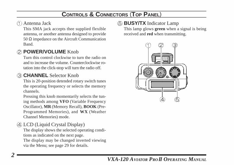
Antenna JackThis SMA jack accepts thee supplied flexibleantenna, or another antenna designed to provide50 Ω impedance on the Aircraft CommunicationBand.
POWER/VOLUME KnobTurn this control clockwise to turn the radio onand to increase the volume. Counterclockwise ro-tation into the click-stop will turn the radio off.
CHANNEL Selector KnobThis is 20-position detended rotary switch tunesthe operating frequency or selects the memorychannels.Pressing this knob momentarily selects the tun-ing methods among VFO (Variable FrequencyOscillator), MR (Memory Recall), BOOK (Pre-Programmed Memories), and WX (WeatherChannel Memories) mode.
LCD (Liquid Crystal Display)The display shows the selected operating condi-tions as indicated on the next page.The display may be changed inverted viewingvia the Menu; see page 29 for details.
BUSY/TX Indicator LampThis lamp glows green when a signal is beingreceived and red when transmitting.
VXA-120 AVIATOR PROII O PERATING MANUAL3
CONTROLS & CONNECTORS (LCD DISPLAY)
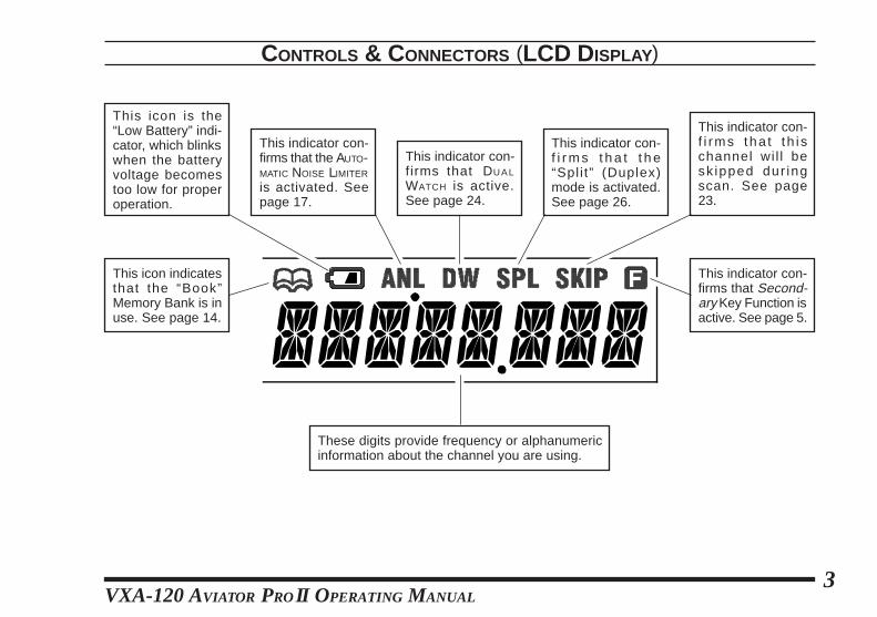
This indicator con-firms that the AUTO-MATIC NOISE LIMITER
is activated. Seepage 17.
This icon is the“Low Battery” indi-cator, which blinkswhen the batteryvoltage becomestoo low for properoperation.
This indicator con-firms that DU A L
WATCH is active.See page 24.
This indicator con-f i r m s t h a t t h e“Spl i t” (Duplex)mode is activated.See page 26.
This indicator con-f i rms tha t t h i schannel wi l l besk ipped dur ingscan. See page23.
These digits provide frequency or alphanumericinformation about the channel you are using.
This icon indicatesthat the “Book”Memory Bank is inuse. See page 14.
This indicator con-firms that Second-ary Key Function isactive. See page 5.
VXA-120 AVIATOR PROII O PERATING MANUAL4
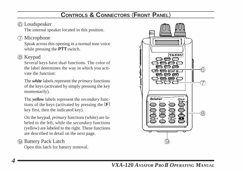
CONTROLS & CONNECTORS (FRONT PANEL)
LoudspeakerThe internal speaker located in this position.
MicrophoneSpeak across this opening in a normal tone voicewhile pressing the PTT switch.
KeypadSeveral keys have dual functions. The color ofthe label determines the way in which you acti-vate the function:
The white labels represent the primary functionsof the keys (activated by simply pressing the keymomentarily).
The yellow labels represent the secondary func-tions of the keys (activated by pressing the [F]key first, then the indicated key).
On the keypad, primary functions (white) are la-beled to the left, while the secondary functions(yellow) are labeled to the right. These functionsare described in detail on the next page.
Battery Pack LatchOpen this latch for battery removal.
VXA-120 AVIATOR PROII O PERATING MANUAL5
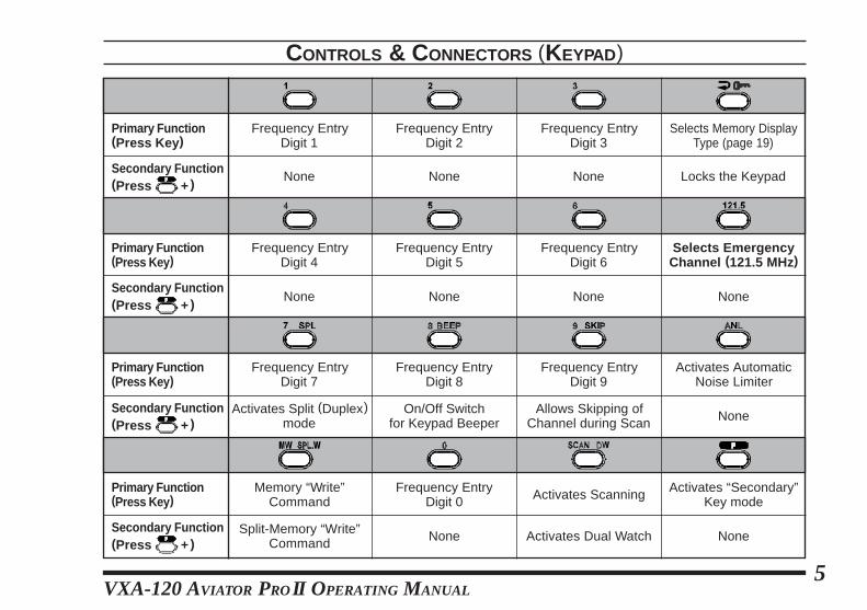
CONTROLS & CONNECTORS (KEYPAD)
Primary Function(Press Key )
Secondary Function(Press + )
Primary Function(Press Key )
Primary Function(Press Key )
Primary Function(Press Key )
Frequency EntryDigit 1
Frequency EntryDigit 2
Frequency EntryDigit 3
Frequency EntryDigit 4
Frequency EntryDigit 5
Frequency EntryDigit 6
Frequency EntryDigit 7
Frequency EntryDigit 8
Frequency EntryDigit 9
Frequency EntryDigit 0
Selects Memory DisplayType (page 19)
Locks the Keypad
Selects EmergencyChannel (121.5 MHz)
None None None
None
NoneNone
Activates AutomaticNoise Limiter
Activates Split (Duplex)mode
On/Off Switchfor Keypad Beeper
Allows Skipping ofChannel during Scan
Activates Scanning Activates “Secondary”Key mode
Activates Dual Watch
Memory “Write”Command
Split-Memory “Write”Command
Secondary Function(Press + )
Secondary Function(Press + )
Secondary Function(Press + )
NoneNoneNone
None
VXA-120 AVIATOR PROII O PERATING MANUAL6
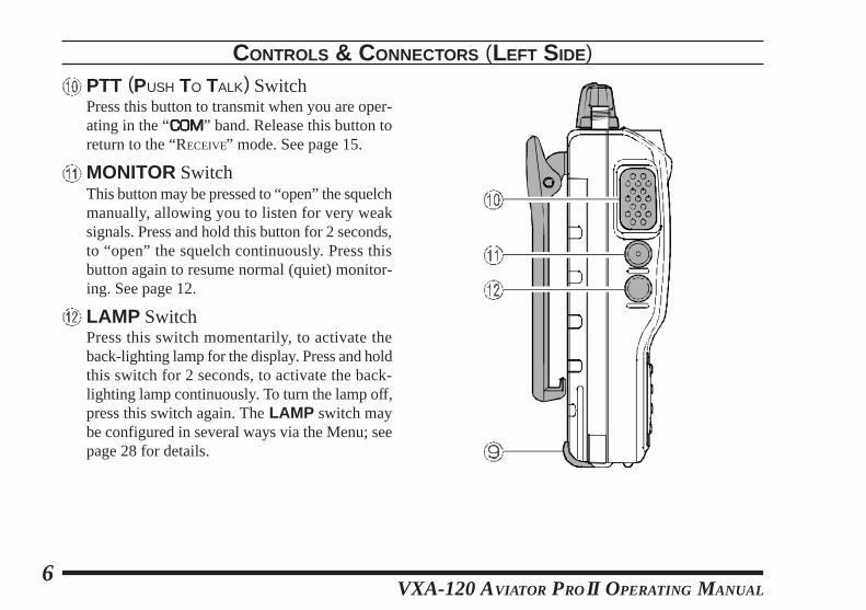
PTT (PUSH TO TALK) SwitchPress this button to transmit when you are oper-ating in the “COMCOMCOMCOMCOM” band. Release this button toreturn to the “RECEIVE” mode. See page 15.
MONITOR SwitchThis button may be pressed to “open” the squelchmanually, allowing you to listen for very weaksignals. Press and hold this button for 2 seconds,to “open” the squelch continuously. Press thisbutton again to resume normal (quiet) monitor-ing. See page 12.
LAMP SwitchPress this switch momentarily, to activate theback-lighting lamp for the display. Press and holdthis switch for 2 seconds, to activate the back-lighting lamp continuously. To turn the lamp off,press this switch again. The LAMP switch maybe configured in several ways via the Menu; seepage 28 for details.
CONTROLS & CONNECTORS (LEFT SIDE)
VXA-120 AVIATOR PROII O PERATING MANUAL7
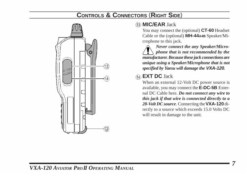
CONTROLS & CONNECTORS (RIGHT SIDE)
MIC/EAR JackYou may connect the (optional) CT-60 HeadsetCable or the (optional) MH-44A4B Speaker/Mi-crophone to this jack.
Never connect the any Speaker/Micro-phone that is not recommended by the
manufacturer. Because these jack connections areunique using a Speaker/Microphone that is notspecified by Yaesu will damage the VXA-120.
EXT DC JackWhen an external 12-Volt DC power source isavailable, you may connect the E-DC-5B Exter-nal DC Cable here. Do not connect any wire tothis jack if that wire is connected directly to a28-Volt DC source. Connecting the VXA-120 di-rectly to a source which exceeds 15.0 Volts DCwill result in damage to the unit.
VXA-120 AVIATOR PROII O PERATING MANUAL8
BEFORE YOU BEGIN
Precautionsr This apparatus is capable of two-way communi-
cation on channels used for critical aviation safetycommunications. Therefore, it is important thatthis radio be kept away from children or otherunauthorized users at all times.
r When making DC connections via the E-DC-5BDC cable, be absolutely certain to observe theproper voltage level and polarity guidelines. Donot connect this radio directly to any 24 ~ 28Volt DC source, nor to AC power of any kind.Connecting the VXA-120 directly to a sourcewhich exceeds 15.0 Volts DC will result in dam-age to the unit.
r Do not dispose of the Ni-Cd Battery Pack in afire. Do not carry a Ni-Cd Battery Pack in yourpocket, where keys or coins could short the ter-minals. This could create a serious fire/burn dan-ger, and possibly cause damage to the Ni-Cdpack.
r Although the VXA-120 is designed to be waterresistant, the enclosure is not “waterproof.” Donot allow the radio to become submersed in wa-ter, and do not expose it and/or its Ni-Cd BatteryPack to water spray under pressure.
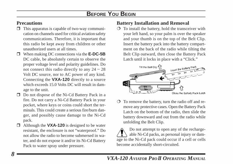
Battery Installation and Removal¦ To install the battery, hold the transceiver with
your left hand, so your palm is over the speakerand your thumb is on the top of the Belt Clip.Insert the battery pack into the battery compart-ment on the back of the radio while tilting theBelt Clip outward, then close the Battery PackLatch until it locks in place with a “Click.”
¦ To remove the battery, turn the radio off and re-move any protective cases. Open the Battery PackLatch on the bottom of the radio, then slide thebattery downward and out from the radio whileunfolding the Belt Clip.
Do not attempt to open any of the recharge-able Ni-Cd packs, as personal injury or dam-
age to the Ni-Cd pack could occur if a cell or cellsbecome accidentally short-circuited.
VXA-120 AVIATOR PROII O PERATING MANUAL9
the charger/battery. Contact your Dealer if youhave any doubts about the appropriateness of theparticular charger or battery pack you intend touse.
BEFORE YOU BEGIN
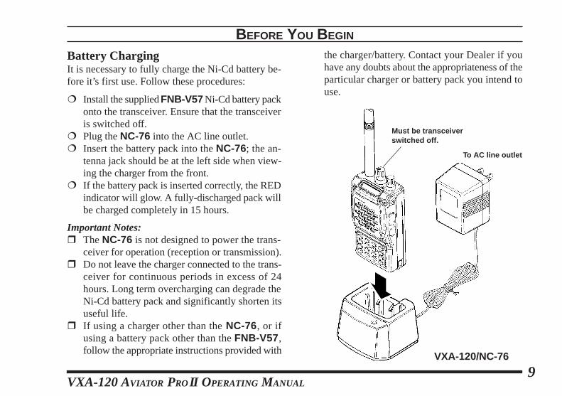
Battery ChargingIt is necessary to fully charge the Ni-Cd battery be-fore it’s first use. Follow these procedures:
¦ Install the supplied FNB-V57 Ni-Cd battery packonto the transceiver. Ensure that the transceiveris switched off.
¦ Plug the NC-76 into the AC line outlet.¦ Insert the battery pack into the NC-76; the an-
tenna jack should be at the left side when view-ing the charger from the front.
¦ If the battery pack is inserted correctly, the REDindicator will glow. A fully-discharged pack willbe charged completely in 15 hours.
Important Notes:r The NC-76 is not designed to power the trans-
ceiver for operation (reception or transmission).r Do not leave the charger connected to the trans-
ceiver for continuous periods in excess of 24hours. Long term overcharging can degrade theNi-Cd battery pack and significantly shorten itsuseful life.
r If using a charger other than the NC-76, or ifusing a battery pack other than the FNB-V57 ,follow the appropriate instructions provided with VXA-120/NC-76
To AC line outlet
Must be transceiverswitched off.
VXA-120 AVIATOR PROII O PERATING MANUAL10
Low Battery Indication¦ As your battery discharges during use, the volt-
age will gradually become lower. When the bat-tery voltage reaches 5.0 Volts, the “x ” iconwill blink on the LCD display, indicating thatthe battery pack must be recharged before fur-ther use.
¦ Avoid recharging Ni-Cd batteries before the“Low Battery” indicator is observed, as this candegrade the charge capacity of your Ni-Cd bat-tery pack. Yaesu recommends that you carry anextra, fully-charged pack with you so you willnot lose communications capability due to a de-pleted Ni-Cd battery.This “deep cycling” practice will help to main-tain longer overall battery life after many recharg-ing cycles.
BEFORE YOU BEGIN
Installing the FBA-25 (option) AlkalineBattery CaseThe optional FBA-25 Battery Case allows opera-tion of the VXA-120 using six “AA” size Alkalinebatteries.
When installing batteries, insert the (–) end first, thenpress in the (+++++) end so the battery snaps into place.Always replace all six batteries at the same time, pay-ing attention to the polarity indicated inside the case.
The FBA-25 must not be used with re-chargeable cells. The FBA-25 does not con-
tain the thermal and over-current protection cir-cuits (provided in the “FNB” series of Ni-Cd Bat-tery Packs) required when utilizing Ni-Cd cells.
VXA-120 AVIATOR PROII O PERATING MANUAL11
OPERATION
Preliminary Steps¦ Install a charged battery pack onto the transceiver,
as described previously.¦ Screw the supplied antenna onto the Antenna
jack. Never operate this transceiver without anantenna connected.
¦ If you have an optional Speaker/Microphone orheadset, we recommend that it not be connecteduntil you are familiar with the basic operation ofthe VXA-120.
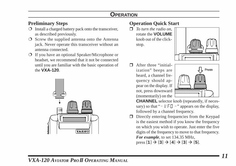
Operation Quick Startr To turn the radio on,
rotate the VOLUMEknob out of the click-stop.
r After three “initial-ization” beeps areheard, a channel fre-quency should ap-pear on the display. Ifnot, press downward(momentarily) on theCHANNEL selector knob (repeatedly, if neces-sary) so that “" VFO "” appears on the display,followed by a channel frequency.
r Directly entering frequencies from the Keypadis the easiest method if you know the frequencyon which you wish to operate. Just enter the fivedigits of the frequency to move to that frequency.For example, to set 134.35 MHz,press [1] à [3] à [4] à [3] à [5].
VXA-120 AVIATOR PROII O PERATING MANUAL12
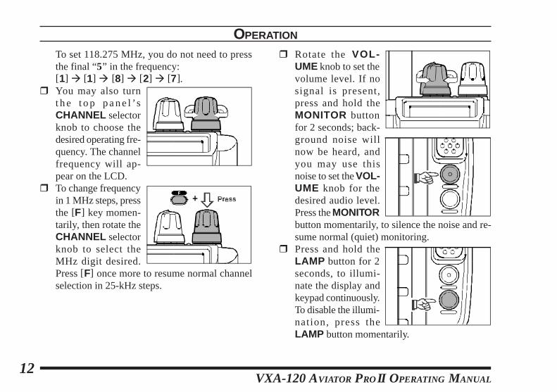
To set 118.275 MHz, you do not need to pressthe final “5” in the frequency:[1] à [1] à [8] à [2] à [7].
r You may also turnthe t op pane l ’sCHANNEL selectorknob to choose thedesired operating fre-quency. The channelfrequency will ap-pear on the LCD.
r To change frequencyin 1 MHz steps, pressthe [F] key momen-tarily, then rotate theCHANNEL selectorknob to select theMHz digit desired.Press [F] once more to resume normal channelselection in 25-kHz steps.
OPERATION
r Rotate the VOL-UME knob to set thevolume level. If nosignal is present,press and hold theMONITOR buttonfor 2 seconds; back-ground noise willnow be heard, andyou may use thisnoise to set the VOL-UME knob for thedesired audio level.Press the MONITORbutton momentarily, to silence the noise and re-sume normal (quiet) monitoring.
r Press and hold theLAMP button for 2seconds, to illumi-nate the display andkeypad continuously.To disable the illumi-nation, press theLAMP button momentarily.
VXA-120 AVIATOR PROII O PERATING MANUAL13
r To turn the radio off, turn the VOLUME knobfully counter-clockwise into the click stop posi-tion.
OPERATION
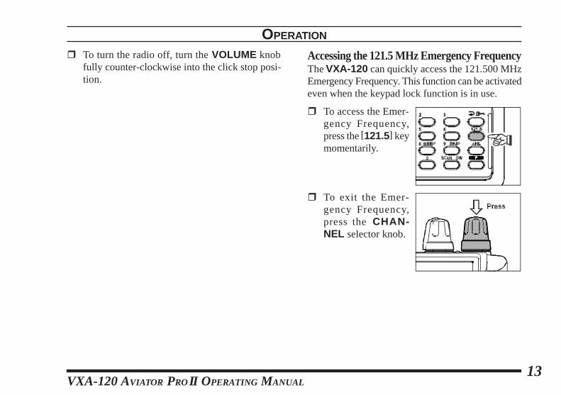
Accessing the 121.5 MHz Emergency FrequencyThe VXA-120 can quickly access the 121.500 MHzEmergency Frequency. This function can be activatedeven when the keypad lock function is in use.
r To access the Emer-gency Frequency,press the [121.5] keymomentarily.
r To exit the Emer-gency Frequency,press the CHAN-NEL selector knob.

VXA-120 AVIATOR PROII O PERATING MANUAL14
Tuning MethodsThroughout this manual, you will see references toseveral different frequency setting methods. Each willbe particularly useful in a particular operating situa-tion, and they are described below:
¦ VFO (Variable Frequency Oscillator)The VFO is a “tuningdial” system which al-l ows you to t unethrough the NAVNAVNAVNAVNAV or COMCOMCOMCOMCOM bands in 25-kHz stepsusing the CHANNEL selector, the Keypad, orthe scanner.
¦ MR (Memory Recall)The MR (Memory Re-call) mode of the VXA-120 provides the userwith the ability to store and recall as many as 50channels in the radio’s main memory bank. Thesememory channels may also be labeled by youwith an alpha/numeric name of up to 8 charac-ters in length, to aid in quick identification ofthe channel. See page 20 for details on creatingalpha/numeric labels.
¦ BOOK (Pre-Programmed) MemoriesThe Book memories arepre-programmed, eitherat the factory or by yourDealer (depending on your country’s require-ments), typically including the major COMCOMCOMCOMCOM andNAVNAVNAVNAVNAV band station frequencies used in your area.The Book memories can be changed by the user.See page 27 for details.
¦ WX (Weather Channel) MemoriesTen Weather Channelsare pre-programmed atthe factory as appropri-ate for your country, and the VXA-120 will au-tomatically scan this special bank when it is se-lected by the user.
OPERATION
VXA-120 AVIATOR PROII O PERATING MANUAL15
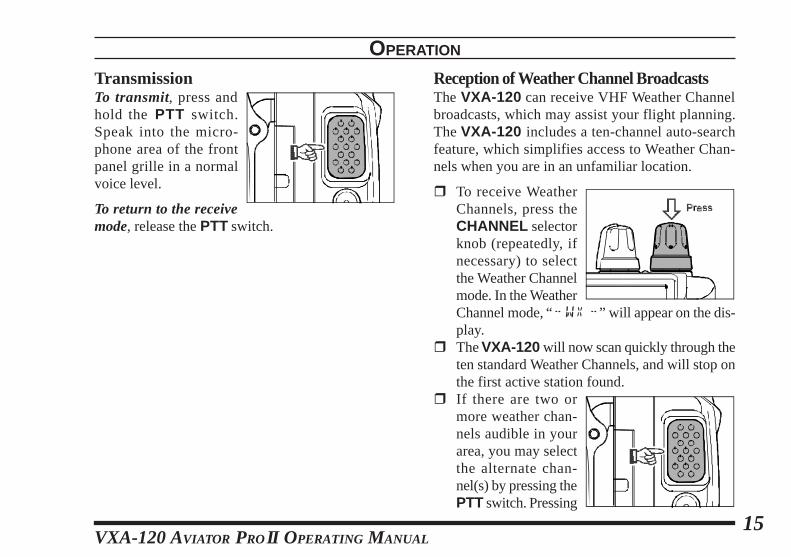
TransmissionTo transmit, press andhold the PTT switch.Speak into the micro-phone area of the frontpanel grille in a normalvoice level.
To return to the receivemode, release the PTT switch.
Reception of Weather Channel BroadcastsThe VXA-120 can receive VHF Weather Channelbroadcasts, which may assist your flight planning.The VXA-120 includes a ten-channel auto-searchfeature, which simplifies access to Weather Chan-nels when you are in an unfamiliar location.
r To receive WeatherChannels, press theCHANNEL selectorknob (repeatedly, ifnecessary) to selectthe Weather Channelmode. In the WeatherChannel mode, “" WX "” will appear on the dis-play.
r The VXA-120 will now scan quickly through theten standard Weather Channels, and will stop onthe first active station found.
r If there are two ormore weather chan-nels audible in yourarea, you may selectthe alternate chan-nel(s) by pressing thePTT switch. Pressing
OPERATION
VXA-120 AVIATOR PROII O PERATING MANUAL16
OPERATION
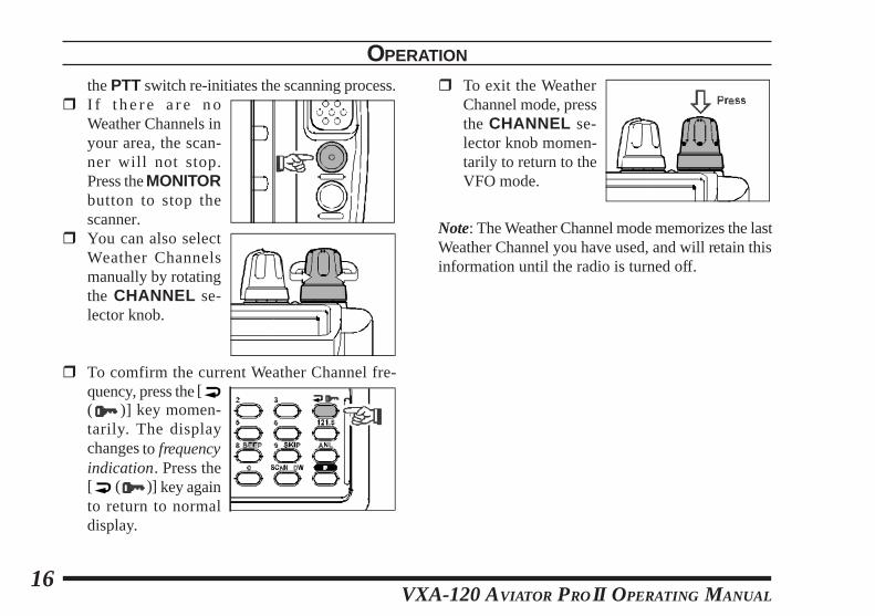
the PTT switch re-initiates the scanning process.r I f t h e r e a r e n o
Weather Channels inyour area, the scan-ner will not stop.Press the MONITORbutton to stop thescanner.
r You can also selectWeather Channelsmanually by rotatingthe CHANNEL se-lector knob.
r To comfirm the current Weather Channel fre-quency, press the [( )] key momen-tarily. The displaychanges to frequencyindication. Press the[ ( )] key againto return to normaldisplay.
r To exit the WeatherChannel mode, pressthe CHANNEL se-lector knob momen-tarily to return to theVFO mode.
Note: The Weather Channel mode memorizes the lastWeather Channel you have used, and will retain thisinformation until the radio is turned off.
VXA-120 AVIATOR PROII O PERATING MANUAL17
Monitor KeyWhen listening to a very weak signal from an air-craft or ground station, you may observe the signaldisappearing periodically as the incoming signalstrength becomes too weak to override the squelchthreshold setting.
To disable the squelchtemporarily, press andhold the MONITOR keyfor 2 seconds on the leftside of the radio, just be-low the PTT button. Thesquelch will remain openand you should have a better chance of hearing weaksignals.
To return to normal operation, press the MONITORkey momentarily.
OPERATION
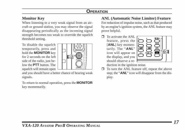
ANL (Automatic Noise Limiter) FeatureFor reduction of impulse noise, such as that producedby an engine’s ignition system, the ANL feature mayprove helpful.
r To activate the ANLfeature, press the[ANL ] key momen-tarily. The “ANL ”icon will appear onthe display, and youshould observe a re-duction in the ignition noise.
r To turn the ANL feature off, repeat the abovestep; the “ANL ” icon will disappear from the dis-play.
VXA-120 AVIATOR PROII O PERATING MANUAL18
LOCK FunctionThe lock function prevents accidental changes to thefrequency setting and the keypad controls.
r To activate the lockfeature, press [F] à[ ( )] key.
r In the LOCK mode,the display will show“ " LOCK"” wheny o u r o t a t e t h eCHANNEL selector knob, press the CHANNELselector knob, or touch a key on the keypad.
r To turn the lock feature off,press [F] à [ ( )] again.
r You can still access the 121.500 MHz EmergencyFrequency when the LOCK function is on.Simply press the [121.5] key momentarily (thiskey never locks). Pressing this key also unlocksthe radio.
OPERATION
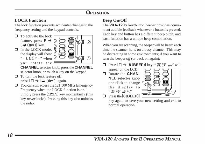
Beep On/OffThe VXA-120’s key/button beeper provides conve-nient audible feedback whenever a button is pressed.Each key and button has a different beep pitch, andeach function has a unique beep combination.
When you are scanning, the beeper will be heard eachtime the scanner halts on a busy channel. This maybe distracting in some environments; if you want toturn the beeper off (or back on again):
r Press [F] à [8 (BEEP)] key; “BEEP on” willappear on the LCD.
r Rotate the CHAN-NEL selector knobone click to changet h e d i s p l a y t o“ BEEP oFF.”
r Press the [8 (BEEP)]key again to save your new setting and exit tonormal operation.
VXA-120 AVIATOR PROII O PERATING MANUAL19
NOTE
VXA-120 AVIATOR PROII O PERATING MANUAL20
MEMORY OPERATION
The VXA-120 provides 50 user-programmable“Main” memories, labeled “CH"))! ” through“ CH")%),” and up to 100 pre-programmed memo-ries, designated “Book” Memories. The “ ” iconappears when “Book” Memory Mode is activated.
The Main memories and “Book” Memories can beassigned alpha-numeric names of up to eight charac-ters.
Memory System OperationThe VXA-120 ’s Main Memory system allows theuser to store, label, and recall channel frequencieswhich you may want to use frequently. You may storeVFO frequencies, Book Memory frequencies, and/or Weather Channel frequencies into the MainMemory system.
Memory Storager Select the desired frequency in the VFO mode,
or recall the Book Memory channel or Weatherchannel to be stored in the Main Memory.
r Press and hold the [MW (SPL.W )] key for 2seconds. The display will indicate “CH"” and achannel number will blink on the LCD.
r Within five seconds of pressing the [MW(SPL.W)] key, rotate the CHANNEL selectorknob to select the desired memory channel num-ber for storage.In order to prevent writing over memory chan-nels, a bar will appear under the hyphen (locatedbetween “CH” and the channel number) to indi-cate a vacant memory channel.
r Now press and hold in the [MW (SPL.W)] keyfor 2 seconds; you will now see “;"""""""""""""""""""""""""""""""""""”on the LCD. To attach an alpha/numeric name(label) to the memory, proceed to the next step;otherwise press and hold [MW (SPL.W)] for 2seconds to save the entry and exit.
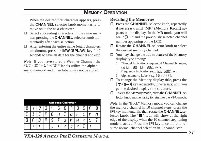
r To label a memory with an alpha/numeric name,the next step is to use the CHANNEL selectorknob to select any of the 48 available characters(including letters, numbers, and special symbols).
VXA-120 AVIATOR PROII O PERATING MANUAL21
When the desired first character appears, pressthe CHANNEL selector knob momentarily tomove on to the next character.
r Select succeeding characters in the same man-ner, pressing the CHANNEL selector knob mo-mentarily after each selection.
r After entering the entire name (eight charactersmaximum), press the [MW (SPL.W)] key for 2seconds to save all data for the channel and exit.
Note: If you have stored a Weather Channel, the“ WX"))! ~ WX")!) ” labels utilize the alphanu-meric memory, and other labels may not be stored.
Recalling the Memoriesr Press the CHANNEL selector knob, repeatedly
if necessary, until “MR” (Memory Recall) ap-pears on the display. In the MR mode, you willsee “CH"” and the previously selected channelnumber appearing on the LCD.
r Rotate the CHANNEL selector knob to selectthe desired memory channel.
r You may change the title structure of the Memorydisplay type among:1. Channel Indication (sequential Channel Number,
e.g. CH"))!, CH"))@, etc.);2. Frequency Indication (e.g. 1@@.%))); or3. Alphanumeric Label (e.g. LAX FSS).
r To change the Memory display title, press the[ ( )] key repeatedly, if necessary, until youget the desired display title structure.
r To exit the Memory mode, press the CHANNEL se-lector knob momentarily to return to the VFO mode.
Note: In the “Book” Memory mode, you can changethe memory channel in 10 channel steps, press the[F] key momentarily, then rotate the CHANNEL se-lector knob. The “ ” icon will show at the rightedge of the display when the 10 channel step tuningmode is active. Press the [F] key once more to re-sume normal channel selection in 1 channel step.
MEMORY OPERATION
AAAAllllpppphhhhaaaa----ttttaaaag g g g CCCChahahaharrrracacacacttttoooorrrr
) ! @ # $ % ^ & * ( A B
C D E F G H I J K L M N
O P Q R S T U V W X Y Z
< > + ; : \ ` y [ | "
VXA-120 AVIATOR PROII O PERATING MANUAL22
SCANNING OPERATION
The VXA-120 allows you to scan automatically inthe VFO*, Main Memory, “Book” Memory, orWeather Channel modes. It pauses on signals encoun-tered, so you can talk to the station(s) on that fre-quency, if you like.
* In the VFO mode, the automatic scanner is onlyavailable in the COMCOMCOMCOMCOM band (118.000 - 136.975 MHz);when the scanner reaches the uppermost frequencyin the COMCOMCOMCOMCOM band, it will revert to the bottom end ofthe COMCOMCOMCOMCOM band and repeat the scanning process untilyou cancel the scanning process.
If you wish to scan in the NAVNAVNAVNAVNAV band (108.000 -136.975 MHz), you can do so manually, as describedat the right.
Scanning operation is basically the same in each ofthe above modes.
r Press the [SCAN (DW)] key momentarily to startthe automatic scanner upward (toward a higherfrequency or a higher channel number).
r When the scanner encounters a signal, scanningpauses and the radio remains on that channel untilone second after the signal disappears, afterwhich scanning will resume.
r While the scanner remains paused on a frequency,the decimal point of the frequency display blinks.The display and keypad will be illuminated un-less the Scan Lamp Feature is turned off.
r To change the scan direction, turn the CHAN-NEL selector knob one click in the opposite di-rection.
r To stop the automatic scanner, press the PTT switchor the CHANNEL selector knob momentarily. Youmay also press [SCAN (DW)] key again.
The VXA-120’s automatic scanner is not operationalin the NAVNAVNAVNAVNAV band (108.000 - 117.975 MHz), becausethe NAVNAVNAVNAVNAV stations (ILS, etc.) transmit constantly(thereby causing the scanner to stop repeatedly).However, you can scan manually in the NAVNAVNAVNAVNAV band,per the following procedure:
r Press and hold the [SCAN (DW)] key to startthe manual scanner. Scanning will continue aslong as the key is depressed.
r Release the [SCAN (DW)] key to stop themanual scanner immediately.
Note: When scanning upward in frequency, when thefrequency reaches the COMCOMCOMCOMCOM Band (118.000 - 136.975MHz) via manual scanning, the VXA-120 will switchto the automatic scanner mode.
VXA-120 AVIATOR PROII O PERATING MANUAL23
SCANNING OPERATION
Channel-Skip ScanningContinuous-carrier stations like ATIS (AutomaticTerminal Information Service) or Weather Broadcaststations inhibit scanner operation. Since these sta-tions are always active, the scanner will be haltedrepeatedly on their channels. Such channels can beset to be “skipped” during scanning, if you like, soas not to interfere with automatic channel scanning:
r Recall the Memory Channel to be skipped dur-ing scanning.
r Press [F] à [9 (SKIP)] key. The “SKIP” iconwill appear in the lower right corner, indicatingthat the channel is to be ignored during scanning.
r You can also designate a channel to be skippedwhile scanning. When the receiver is halted on achannel that you wish to skip, press and hold the[SCAN (DW)] key for 2 seconds (the “SKIP”icon will appear next to the channel to beskipped).
r Later, to re-enable the memory channel for scan-ning, repeat the first two steps. The “SKIP” iconwill disappear by the channel you have just re-enabled.
Note: A memory set to be “skipped” is still acces-sible for manual memory selection using the CHAN-NEL selector knob.
VXA-120 AVIATOR PROII O PERATING MANUAL24
DUAL WATCH OPERATION
The Dual Watch feature automatically checks foractivity on a “priority” channel* while you are oper-ating on another channel. During Dual Watch opera-tion, the current channel and the Priority channel willeach be polled for a 500 ms interval, as the VXA-120 looks for activity on each channel.
r To start Dual Watch, press [F] à [SCAN (DW)].The “DW” icon will appear on the display.
r While receiving on the “current” channel (notthe Priority channel), you may push the PTTswitch at any time to transmit on that channel.
r When a signal is received on the Priority chan-nel, operation immediately shifts to the Prioritychannel, the “DW” icon will blink, and the dis-play and keypad will become illuminated.
While receiving on the priority channel, if youmomentarily press the PTT switch, Dual Watchwill be disabled. You may then transmit on thePriority Channel.
r To stop Dual Watch, press [F] à [SCAN (DW)]key.
r If you wish, you may use both the Dual Watchand Scan features simultaneously. To do this, startthe Dual Watch first, then start the Scanner.
* The “Priority” Channel is defined as the last-usedMemory Channel (when using the VFO mode) orMemory Channel 1 (when using the Main Memoryor Book Memory modes).
VXA-120 AVIATOR PROII O PERATING MANUAL25
PRIORITY DUAL WATCH OPERATION
Similar to Dual Watch operation (described above),Priority Dual Watch is an enhanced version whichincludes the following additional features:
l The receiving time interval (ratio) between thecurrent channel and the Priority channel may becustomized via the Menu mode, item PRTM. Seepage 28 for details.
l Irrespective of which channel is currently beingreceived, when the PTT button is pushed trans-mission will always occur on the Priority chan-nel.
Before initiating Priority Dual Watch, Menu itemDWMD must be set to the “Priority” mode (insteadof “Dual Watch”). See page 28 for details.
r To start Priority Dual Watch, press [F] à [SCAN(DW)].The “DW” icon will appear on the display.
r While receiving on the “current” (non-Priority)channel, pressing the PTT button once causesthe radio to switch to the Priority channel andcancels Dual Watch. Press the PTT button againto transmit on the Priority channel.
r When a signal is received on the Priority chan-nel, reception immediately shifts to the Prioritychannel, “DW” icon will blink, and the displayand keypad will become illuminated unless theScan Lamp Feature is turned off.While receiving on the priority channel, if youmomentarily press the PTT switch, Priority DualWatch will be disabled. You may then transmiton the Priority Channel.
r To stop Priority Dual Watch, press [F] à [SCAN(DW)] key.
VXA-120 AVIATOR PROII O PERATING MANUAL26
The split operation feature allows you to transmit acall to a Flight Service Station using the COMCOMCOMCOMCOM bandfrequencies, while receiving a NAVNAVNAVNAVNAV band station(such as the ATIS, AWOS etc.). NAVNAVNAVNAVNAV band stationsequipped with this capability typically are shown,on navigation charts, with the voice calling frequencyin parenthesis above the navigation frequency.
Programming a Transmit Frequencyr Press the CHANNEL selector knob, repeatedly
if necessary, to select the VFO mode.r Set a NAVNAVNAVNAVNAV band (108.000 - 117.975 MHz) fre-
quency using the CHANNEL selector knob orkeypad.
r Press [F] à [MW (SPL.W)] key. The “SPL”icon will blink, and the transmit frequency willappear on the display.
r Now set your radio’s transmit frequency, wherethe Flight Service Station will be listening forcalls, using the CHANNEL selector knob or key-pad.
r Press and hold in the [MW (SPL.W)] key for 2seconds to save the transmit frequency and re-turn to the NAVNAVNAVNAVNAV band frequency.
SPLIT OPERATION
Note: You have now stored the separate transmit fre-quency, but you have not yet activated the split-fre-quency function; go on to the next section.
Operating in the Split Moder It is assumed that you have already set the de-
sired NAVNAVNAVNAVNAV band station’s frequencies per theabove instructions.
r Press [F] à [7 (SPL)] to turn on the “Split”function. The “SPL” icon will appear on the dis-play.
r Press and hold in the PTT switch to transmit onthe split transmit frequency.
r Release the PTT switch to return to the receivemode.
r To disable the “Split” function, press [F] à [7(SPL)] again.
Note: A split frequency can be programmed into eachmemory channel independently. Set a transmit fre-quency before programming the memory channel, ifdesired. The split function on/off setting can also beprogrammed into a memory channel.
VXA-120 AVIATOR PROII O PERATING MANUAL27
FIELD PROGRAMMING MODE
The VXA-120’s Book Memoris also allows the userto store, label, and recall channel frequencies whichyou may want to use frequently while the VXA-120is in the Field Programming mode.
Memory Storage into the Book Memoryr Press and hold the PTT and LAMP switch while
turning the radio on, to activate the Field Pro-gramming Mode.
r Select the desired frequency to be stored in theBook Memory.
r Press and hold the [MW(SPL.W)] key for 2 sec-onds. The display will indicate “BOOK;” and achannel number will blink on the LCD.
r With in f i ve seconds o f press ing the[MW(SPL.W)] key, rotate the CHANNEL se-lector knob to select the desired memory chan-nel number for storage.
r Now press and hold in the [MW(SPL.W)] keyfor 2 seconds; you will now see “;"""""""”on the LCD. To attach an alpha/numeric name(label) to the memory, proceed to the next step;otherwise press and hold the [MW(SPL.W)] keyfor 2 seconds to save the entry and exit.
r To label a memory with an alpha/numeric name,the next step is to use the CHANNEL selectorknob to select any of the 48 available characters(including letters, numbers, and special symbols).When the desired first character appears, pressdown on the CHANNEL selector knob momen-tarily to move on to the next character.
r Select succeeding characters in the same man-ner, pressing down on the CHANNEL selectorknob momentarily after each selection.
r After entering the entire name (eight charactersmaximum), press the [MW(SPL.W)] key for 2seconds to save all data for the channel.
r Turn the radio off, then turn the radio back onagain to begin normal operation.

VXA-120 AVIATOR PROII O PERATING MANUAL28
MENU (“S ET” ) MODE
The Menu system allows certain aspects of yourradio’s configuration to be customized for your per-sonal operating convenience. We do not recommendthat any of the default settings be changed, however,until you are thoroughly familiar with the operationof the VXA-120.
1. Press the [F] key, thenpress the CHANNELselector knob to activatethe Menu ( “SET”)mode.
2. Rotate the CHANNELselector knob to selectthe Menu item (feature)you wish to view and/ormodify.
3. Once you have selectedthe desired Menu Item,press the CHANNELselector knob once toview the current settingfor the item.
4. Rotate the CHANNELselector knob to changethe setting of the item(ON to OFF, etc.).
5. Press the CHANNELselector knob to saveyour new setting.
6. If you need to changemore than one Menuitem, repeat steps 2 - 5.
7. Press the PTT switch toexit the Menu (“SET”)mode.
VXA-120 AVIATOR PROII O PERATING MANUAL29
MENU (“S ET” ) MODE
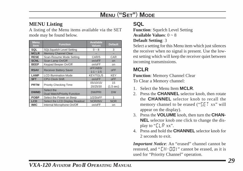
MENU ListingA listing of the Menu items available via the SETmode may be found below.
SQLFunction: Squelch Level SettingAvailable Values: 0 ~ 8Default Setting: 3Select a setting for this Menu item which just silencesthe receiver when no signal is present. Use the low-est setting which will keep the receiver quiet betweenincoming transmissions.
MCLRFunction: Memory Channel ClearTo Clear a Memory channel:
1. Select the Menu Item MCLR.2. Press the CHANNEL selector knob, then rotate
the CHANNEL selector knob to recall thememory channel to be erased (“SET xx” willappear on the display).
3. Press the VOLUME knob, then turn the CHAN-NEL selector knob one click to change the dis-play to “CLR xx”.
4. Press and hold the CHANNEL selector knob for2 seconds to exit.
Important Notice: An “erased” channel cannot berestored, and “CH"OO1” cannot be erased, as it isused for “Priority Channel” operation.
MenuItem
SQLMCLRRESESCNLBEEP
RSAV
LAMPSFT
PRTM
DWMD
POBPLCDIMIC
Function
SQLSquelch Level SettingMemory Channel ClearScan-Resume Mode SettingScan Lamp On/OffKeypad Beeper On/Off
Receiver Battery Saver
LCD Illumination ModeCPU Clock Shift
Priority Checking Time
Select theDual Watch/Priority FunctionSelect the Power on BeepSelect the LCD Display ReadoutInternal Microphone On/Off
AvailableValues0 ~ 8
–CAR/5on/oFFon/oFF
oFF/ABS/1:1 ~ 1:5
KEY/TGL/5on/oFF
05/10/15/20/25/30
DW/PRI
1/2/3/oFFNOR/INVon/oFF
Default
3–
CARonon
oFF
KEYoFF15
(1.5 sec)
DW
1NOR
on
VXA-120 AVIATOR PROII O PERATING MANUAL30
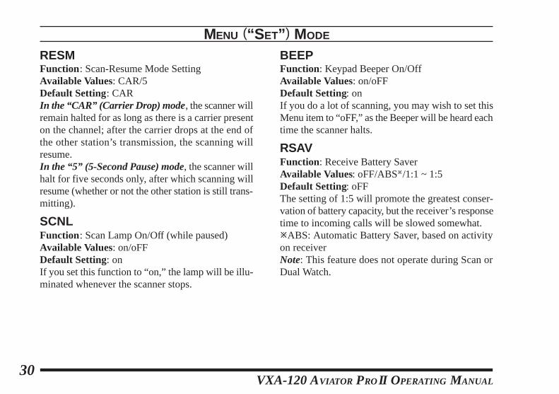
RESMFunction: Scan-Resume Mode SettingAvailable Values: CAR/5Default Setting: CARIn the “CAR” (Carrier Drop) mode, the scanner willremain halted for as long as there is a carrier presenton the channel; after the carrier drops at the end ofthe other station’s transmission, the scanning willresume.In the “5” (5-Second Pause) mode, the scanner willhalt for five seconds only, after which scanning willresume (whether or not the other station is still trans-mitting).
SCNLFunction: Scan Lamp On/Off (while paused)Available Values: on/oFFDefault Setting: onIf you set this function to “on,” the lamp will be illu-minated whenever the scanner stops.
BEEPFunction: Keypad Beeper On/OffAvailable Values: on/oFFDefault Setting: onIf you do a lot of scanning, you may wish to set thisMenu item to “oFF,” as the Beeper will be heard eachtime the scanner halts.
RSAVFunction: Receive Battery SaverAvailable Values: oFF/ABSø/1:1 ~ 1:5Default Setting: oFFThe setting of 1:5 will promote the greatest conser-vation of battery capacity, but the receiver’s responsetime to incoming calls will be slowed somewhat.øABS: Automatic Battery Saver, based on activityon receiverNote: This feature does not operate during Scan orDual Watch.
MENU (“S ET” ) MODE
VXA-120 AVIATOR PROII O PERATING MANUAL31
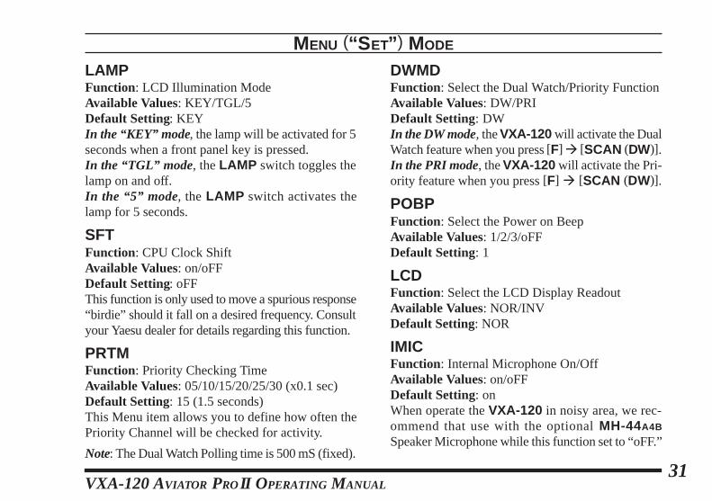
LAMPFunction: LCD Illumination ModeAvailable Values: KEY/TGL/5Default Setting: KEYIn the “KEY” mode, the lamp will be activated for 5seconds when a front panel key is pressed.In the “TGL” mode, the LAMP switch toggles thelamp on and off.In the “5” mode, the LAMP switch activates thelamp for 5 seconds.
SFTFunction: CPU Clock ShiftAvailable Values: on/oFFDefault Setting: oFFThis function is only used to move a spurious response“birdie” should it fall on a desired frequency. Consultyour Yaesu dealer for details regarding this function.
PRTMFunction: Priority Checking TimeAvailable Values: 05/10/15/20/25/30 (x0.1 sec)Default Setting: 15 (1.5 seconds)This Menu item allows you to define how often thePriority Channel will be checked for activity.
Note: The Dual Watch Polling time is 500 mS (fixed).
MENU (“S ET” ) MODE
DWMDFunction: Select the Dual Watch/Priority FunctionAvailable Values: DW/PRIDefault Setting: DWIn the DW mode, the VXA-120 will activate the DualWatch feature when you press [F] à [SCAN (DW)].In the PRI mode, the VXA-120 will activate the Pri-ority feature when you press [F] à [SCAN (DW)].
POBPFunction: Select the Power on BeepAvailable Values: 1/2/3/oFFDefault Setting: 1
LCDFunction: Select the LCD Display ReadoutAvailable Values: NOR/INVDefault Setting: NOR
IMICFunction: Internal Microphone On/OffAvailable Values: on/oFFDefault Setting: onWhen operate the VXA-120 in noisy area, we rec-ommend that use with the optional MH-44A4B
Speaker Microphone while this function set to “oFF.”
VXA-120 AVIATOR PROII O PERATING MANUAL32
SPECIFICATIONS
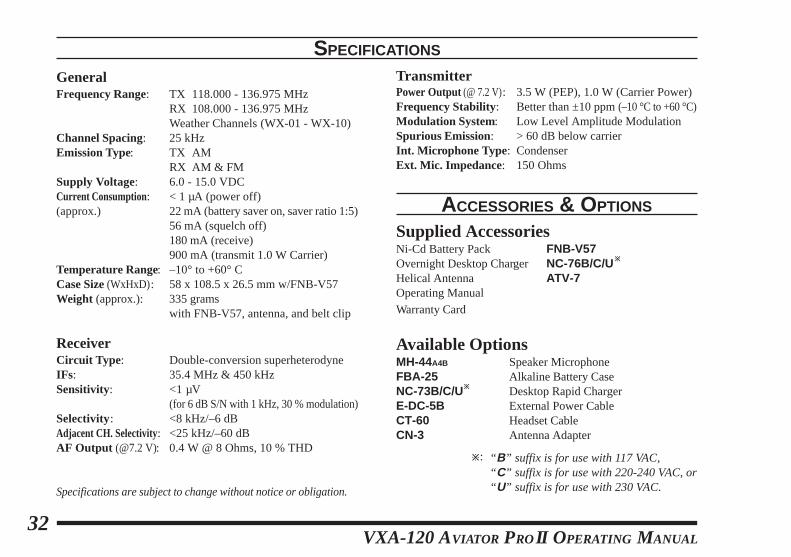
GeneralFrequency Range: TX 118.000 - 136.975 MHz
RX 108.000 - 136.975 MHzWeather Channels (WX-01 - WX-10)
Channel Spacing: 25 kHzEmission Type: TX AM
RX AM & FMSupply Voltage: 6.0 - 15.0 VDCCurrent Consumption: < 1 µA (power off)(approx.) 22 mA (battery saver on, saver ratio 1:5)
56 mA (squelch off)180 mA (receive)900 mA (transmit 1.0 W Carrier)
Temperature Range: –10° to +60° CCase Size (WxHxD): 58 x 108.5 x 26.5 mm w/FNB-V57Weight (approx.): 335 grams
with FNB-V57, antenna, and belt clip
ReceiverCircuit Type : Double-conversion superheterodyneIFs: 35.4 MHz & 450 kHzSensitivity: <1 µV
(for 6 dB S/N with 1 kHz, 30 % modulation)Selectivity: <8 kHz/–6 dBAdjacent CH. Selectivity: <25 kHz/–60 dBAF Output (@7.2 V): 0.4 W @ 8 Ohms, 10 % THD
Specifications are subject to change without notice or obligation.
TransmitterPower Output (@ 7.2 V): 3.5 W (PEP), 1.0 W (Carrier Power)Frequency Stability: Better than ±10 ppm (–10 °C to +60 °C)Modulation System: Low Level Amplitude ModulationSpurious Emission: > 60 dB below carrierInt. Microphone Type: CondenserExt. Mic. Impedance: 150 Ohms
ACCESSORIES & OPTIONS
Supplied AccessoriesNi-Cd Battery Pack FNB-V57Overnight Desktop Charger NC-76B/C/Uø
Helical Antenna ATV-7Operating ManualWarranty Card
Available OptionsMH-44A4B Speaker MicrophoneFBA-25 Alkaline Battery CaseNC-73B/C/Uø Desktop Rapid ChargerE-DC-5B External Power CableCT-60 Headset CableCN-3 Antenna Adapter
ø: “ B” suffix is for use with 117 VAC,“ C” suffix is for use with 220-240 VAC, or“ U” suffix is for use with 230 VAC.