VWR symphony Low-Temp./BOD Incubator
40
Service Manual VWR symphony Low-Temp./BOD Incubator Low-Temp./BOD Incubator: 414004-626,628,630,632 414004-627,629,631,633
Transcript of VWR symphony Low-Temp./BOD Incubator
Service Manual
VWR symphony Low-Temp./BOD Incubator Low-Temp./BOD Incubator: 414004-626,628,630,632
414004-627,629,631,633

www.vwr.com
VWR International, VWR symphony Low-Temp./BOD Incubator 2/40
The manual described herein is designed to assist in timely diagnosis and to provide solutions for
malfunctions that may occur during use. In the event that problems described below do occur, verify fault conditions and perform corrective
actions suggested in this manual. If abnormal conditions persist, contact VWR Equipment and Instrument Service 1-888-793-2300.
Contents
I. Description of Key Parts and Specifications
1. Description of Key Parts …..………………………………………………………………….. 3
2. Specifications ……..………………………………………………...…………..……………… 8
3. Circuit Diagram ………………………………………………………………………………….. 9
II. Corrective Actions for Fault Conditions
1. Power on – no response …………….……………………………………………..…...….. 13
2. Temperature does not increase during operation …………..…………………........ 16
3. Temperature does not decrease during operation …………..……………………...... 23
4. Temperature increases while controller not in operation ………………..……....... 26
5. Temperature decreases while controller not in operation ……………....….......... 27
6. Large temperature offset ………………………………………………………...……….... 29
7. Error 1 during Operation …….……………………………………………………………… 30
8. Error 3 during Operation …..……………………………………………………………… 30
9. Internal circulation fan is not operative ……….………..……………………….……… 32
10. Replacement Instructions for Key Parts ………………….………......................... 34
III. Cautions …………..................………...................................………....................... 39
IV. Spare Parts List …………..................………........................................................ 39

www.vwr.com
VWR International, VWR symphony Low-Temp./BOD Incubator 3/40
I. Description of Key Parts and Specifications
1. Description of Key Parts
Safety Knob
<Figure 1> VWR symphony Low-Temp./BOD Incubator
414004-626,627
RS232C Connector
Main Power Switch
Safety Protector
Fuse
414004-626 : 250V F 15AH
414004-627 : 250V F 15AH
Inner AC Outlet
Control Panel
www.vwr.com
VWR International, VWR symphony Low-Temp./BOD Incubator 4/40
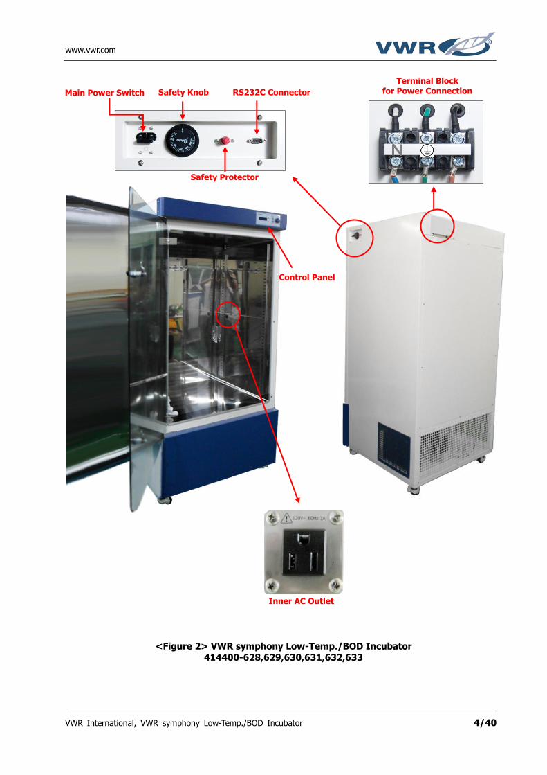
Main Power Switch Safety Knob RS232C Connector
Terminal Block
for Power Connection
Safety Protector
<Figure 2> VWR symphony Low-Temp./BOD Incubator
414400-628,629,630,631,632,633
Control Panel
Inner AC Outlet

www.vwr.com
VWR International, VWR symphony Low-Temp./BOD Incubator 5/40
Safety Knob
SSR for Heater DC/AC type
Main PCB (Controller)
SMPS
<Figure 3> Distribution board of 414004-626,627
Safety Protector
Power Switch
SSR board for Bypass Valve and Circulation Fan
SSR for Compressor DC/AC type
Internal Outlet Fuse : 250V 1AH
<Figure 4> Distribution board of 414004-628,629,630,631
Safety Knob
SSR for Heater DC/AC type
Main PCB (Controller)
SMPS
Circuit Breaker
SSR board for Bypass valve and Circulation Fan
Safety Protector
SSR for Compressor DC/AC type
Internal Outlet Fuse : 250V 1AH

www.vwr.com
VWR International, VWR symphony Low-Temp./BOD Incubator 6/40
Temp. Sensor
+5 V for SSR board
RS232C
DC Power
Compressor and Heater SSR Control (+)
<Figure 6> Main controller of VWR symphony Low Temp./BOD Incubator
Door Limit Switch
Safety Knob
SSR for Heater DC/AC type and AC/AC type
Main PCB (Controller)
SMPS
<Figure 5> Distribution board of 414004-632,633
Circuit Breaker
SSR board for Bypass valve and Circulation Fan
Safety Protector
SSR for Compressor DC/AC type
Heater SSR Control(-)
Internal Fan SSR Control
Bypass SSR Control
Compressor SSR Control(-)
Internal Outlet Fuse : 250V 1AH

www.vwr.com
VWR International, VWR symphony Low-Temp./BOD Incubator 7/40
<Figure 7> Compressor Deck of VWR symphony Low Temp./BOD Incubator
Condenser Motor
Compressor Condenser
www.vwr.com
VWR International, VWR symphony Low-Temp./BOD Incubator 8/40
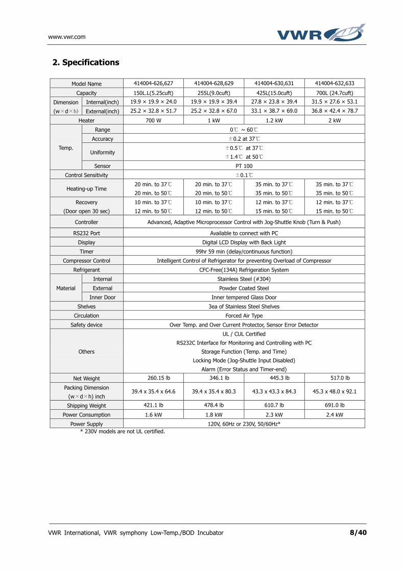
2. Specifications
Model Name 414004-626,627 414004-628,629 414004-630,631 414004-632,633
Capacity 150L.L(5.25cuft) 255L(9.0cuft) 425L(15.0cuft) 700L (24.7cuft)
Dimension
(w×d×h)
Internal(inch) 19.9 × 19.9 × 24.0 19.9 × 19.9 × 39.4 27.8 × 23.8 × 39.4 31.5 × 27.6 × 53.1
External(inch) 25.2 × 32.8 × 51.7 25.2 × 32.8 × 67.0 33.1 × 38.7 × 69.0 36.8 × 42.4 × 78.7
Heater 700 W 1 kW 1.2 kW 2 kW
Temp.
Range 0 ~ 60
Accuracy ±0.2 at 37
Uniformity ±0.5 at 37
±1.4 at 50
Sensor PT 100
Control Sensitivity ±0.1
Heating-up Time 20 min. to 37
20 min. to 50
20 min. to 37
20 min. to 50
35 min. to 37
35 min. to 50
35 min. to 37
35 min. to 50
Recovery
(Door open 30 sec)
10 min. to 37
12 min. to 50
10 min. to 37
12 min. to 50
12 min. to 37
15 min. to 50
12 min. to 37
15 min. to 50
Controller Advanced, Adaptive Microprocessor Control with Jog-Shuttle Knob (Turn & Push)
RS232 Port Available to connect with PC
Display Digital LCD Display with Back Light
Timer 99hr 59 min (delay/continuous function)
Compressor Control Intelligent Control of Refrigerator for preventing Overload of Compressor
Refrigerant CFC-Free(134A) Refrigeration System
Material
Internal Stainless Steel (#304)
External Powder Coated Steel
Inner Door Inner tempered Glass Door
Shelves 3ea of Stainless Steel Shelves
Circulation Forced Air Type
Safety device Over Temp. and Over Current Protector, Sensor Error Detector
Others
UL / CUL Certified
RS232C Interface for Monitoring and Controlling with PC
Storage Function (Temp. and Time)
Locking Mode (Jog-Shuttle Input Disabled)
Alarm (Error Status and Timer-end)
Net Weight 260.15 lb 346.1 lb 445.3 lb 517.0 lb
Packing Dimension
(w×d×h) inch 39.4 x 35.4 x 64.6 39.4 x 35.4 x 80.3 43.3 x 43.3 x 84.3 45.3 x 48.0 x 92.1
Shipping Weight 421.1 lb 478.4 lb 610.7 lb 691.0 lb
Power Consumption 1.6 kW 1.8 kW 2.3 kW 2.4 kW
Power Supply 120V, 60Hz or 230V, 50/60Hz*
* 230V models are not UL certified.

www.vwr.com
VWR International, VWR symphony Low-Temp./BOD Incubator 9/40
3. Circuit Diagram
PT100
SMPS / AC
SMPS / DC
RS-232C
SP210R-7DL
SMPS
DoorLimit Switch
D-SUB
HEATER
Safety Knob Sensor
DC 12V/0.9A
FAN VALVE HEATER LIMIT S/W +5VSENSOR
- + - + - +
CHAMBERAC
OUTLET
FU
SE
Temp. Sensor
FAN_1
FAN_2
Safety Protector Sensor
SafetyProtector
SafetyKnob
80 120
TerminalBlock
12PIN / KEY 14PIN / LCDUI
SMPS / DC RS-232C
12PIN / KEY 14PIN / LCD
14P Flat Cable12P Flat Cable
CONTROLLER
Compressor
Condenser Motor
Ref. Valve
-+
DC/ACSSR
SSR
SSR
-+
DC/ACSSR
CON COOL
2 1 -
V/V_OUT +5VV/V_CONCON
2 1
AC FAN CON
COM OUT OUT CON
AC
COM 2 1
SSR BOARD
AC IN
FU
SE
Main PowerSwitch
I
O
L N
No. Model
Parts Specification
AC Type Fuse DC/AC SSR
Heater Compressor AC Part Wire DC Part Wire
1 414004-626,627 Cable Grand
250V / 15A 215Z 240Z
700W 1/3 Hp(660W) 14AWG/105 18AWG
<Figure 7> Circuit Diagram of 414004-626,627

www.vwr.com
VWR International, VWR symphony Low-Temp./BOD Incubator 10/40
PT100
SMPS / AC
SMPS / DC
RS-232C
SP210R-7DL
SMPS
DoorLimit Switch
D-SUB
HEATER
Safety Knob Sensor
DC 12V/0.9A
FAN VALVE HEATER LIMIT S/W +5VSENSOR
- + - + - +
CHAMBERAC
OUTLETFU
SE
Temp. Sensor
FAN_1
FAN_2
Safety Protector Sensor
SafetyProtector
SafetyKnob
80 120
TerminalBlock
12PIN / KEY 14PIN / LCDUI
SMPS / DC RS-232C
12PIN / KEY 14PIN / LCD
14P Flat Cable12P Flat Cable
CONTROLLER
Compressor
Condenser Motor
FAN_3
Ref. Valve
-+
DC/ACSSR
SSR
SSR
-+
DC/ACSSR
CON COOL
2 1 -
V/V_OUT +5VV/V_CONCON
2 1
AC FAN CON
COM OUT OUT CON
AC
COM 2 1
SSR BOARD
AC IN
FU
SE
Main PowerSwitch
I
O
L N
No. Model
Parts Specification
AC Type Fuse DC/AC SSR
Heater Compressor AC Part Wire DC Part Wire
1 414004-628,629 Terminal
Block 250V / 30A
Circuit Breaker 215Z 240Z
1kW 1/3 Hp(660W) 10AWG/105 18AWG
<Figure 8> Circuit Diagram of 414004-628,629

www.vwr.com
VWR International, VWR symphony Low-Temp./BOD Incubator 11/40
PT100
SMPS / AC
SMPS / DC
RS-232C
SP210R-7DL
SMPS
DoorLimit Switch
D-SUB
HEATER
Safety Knob Sensor
DC 12V/0.9A
FAN VALVE HEATER LIMIT S/W +5VSENSOR
- + - + - +
CHAMBERAC
OUTLETFU
SE
Temp. Sensor
FAN_1
FAN_2
FAN_3
Safety Protector Sensor
SafetyProtector
SafetyKnob
80 120
TerminalBlock
12PIN / KEY 14PIN / LCDUI
SMPS / DC RS-232C
12PIN / KEY 14PIN / LCD
14P Flat Cable12P Flat Cable
CONTROLLER
TERMINALBLOCK
Compressor
Condenser Motor
FAN_4
Ref. Valve
-+
DC/ACSSR
SSR
SSR
-+
DC/ACSSR
CON COOL
2 1 -
V/V_OUT +5VV/V_CONCON
2 1
AC FAN CON
COM OUT OUT CON
AC
COM 2 1
TerminalBlock
SSR BOARD
Main PowerSwitch
Circuit Breaker
I
O
L N
No. Model
Parts Specification
AC Type AC/AC SSR
DC/AC SSR
Heater Compressor AC Part Wire DC Part Wire
1 414004-630,631 Terminal Block none 215Z 240Z
1.2kW 2/5 Hp(800W) 10AWG/105 18AWG
<Figure 9> Circuit Diagram of 414004-630,631

www.vwr.com
VWR International, VWR symphony Low-Temp./BOD Incubator 12/40
PT100
SMPS / AC
SMPS / DC
RS-232C
SP210R-7DL
SMPS
DoorLimit Switch
D-SUB
HEATER
Safety Knob Sensor
DC 12V/0.9A
FAN VALVE HEATER LIMIT S/W +5VSENSOR
- + - + - +
FU
SE
Temp. Sensor
FAN_1
FAN_2
FAN_3
Safety Protector Sensor
SafetyProtector
SafetyKnob
80 120
TerminalBlock
12PIN / KEY 14PIN / LCDUI
SMPS / DC RS-232C
12PIN / KEY 14PIN / LCD
14P Flat Cable12P Flat Cable
CONTROLLER
TERMINALBLOCK
INPUT
AC/ACSSR
LOAD
Compressor
Condenser Motor
FAN_4
Ref. Valve
-+
DC/ACSSR
SSR
SSR
-+
DC/ACSSR
CON COOL
2 1 -
V/V_OUT +5VV/V_CONCON
2 1
AC FAN CON
COM OUT OUT CON
AC
COM 2 1
TerminalBlock
SSR BOARD
CHAMBERAC
OUTLET
Main PowerSwitch
Circuit Breaker
I
O
L N
No. Model
Parts Specification
AC Type AC/AC SSR
DC/AC SSR
Heater Compressor AC Part Wire DC Part Wire
1 414004-632,633 Terminal Block 40AA 225Z 240Z
2kW 1/2 Hp(1kW) 10AWG/105 18AWG
<Figure 10> Circuit Diagram of 414004-632,633
www.vwr.com
VWR International, VWR symphony Low-Temp./BOD Incubator 13/40
II. Corrective Actions for Fault Conditions 1. Power on – no response
(1) Check the power cord is plugged in correctly. - Verify unit power cord is securely plugged into proper power socket.
- If power cord is plugged in correctly, go to next instruction..
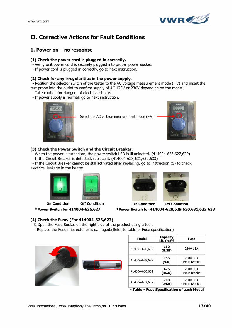
(2) Check for any irregularities in the power supply.
- Position the selector switch of the tester to the AC voltage measurement mode (~V) and insert the test probe into the outlet to confirm supply of AC 120V or 230V depending on the model.
- Take caution for dangers of electrical shocks. - If power supply is normal, go to next instruction.
(3) Check the Power Switch and the Circuit Breaker. - When the power is turned on, the power switch LED is illuminated. (414004-626,627,629)
- If the Circuit Breaker is defected, replace it. (414004-628,631,632,633) - If the Circuit Breaker cannot be still activated after replacing, go to instruction (5) to check
electrical leakage in the heater.
(4) Check the Fuse. (For 414004-626,627)
① Open the Fuse Socket on the right side of the product using a tool.
- Replace the Fuse if its exterior is damaged.(Refer to table of Fuse specification)
Select the AC voltage measurement mode (~V)
Off Condition On Condition
*Power Switch for 414004-626,627 *Power Switch for 414004-628,629,630,631,632,633
Off Condition On Condition
Model Capacity Lit. (cuft)
Fuse
414004-626,627 150
(5.25) 250V 15A
414004-628,629 255 (9.0)
250V 30A Circuit Breaker
414004-630,631 425
(15.0) 250V 30A
Circuit Breaker
414004-632,632 700
(24.5) 250V 30A
Circuit Breaker
<Table> Fuse Specification of each Model
www.vwr.com
VWR International, VWR symphony Low-Temp./BOD Incubator 14/40
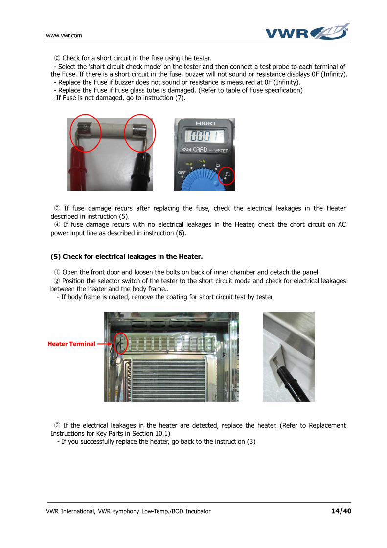
② Check for a short circuit in the fuse using the tester.
- Select the ‘short circuit check mode’ on the tester and then connect a test probe to each terminal of the Fuse. If there is a short circuit in the fuse, buzzer will not sound or resistance displays 0F (Infinity).
- Replace the Fuse if buzzer does not sound or resistance is measured at 0F (Infinity). - Replace the Fuse if Fuse glass tube is damaged. (Refer to table of Fuse specification)
-If Fuse is not damaged, go to instruction (7).
③ If fuse damage recurs after replacing the fuse, check the electrical leakages in the Heater
described in instruction (5).
④ If fuse damage recurs with no electrical leakages in the Heater, check the chort circuit on AC
power input line as described in instruction (6).
(5) Check for electrical leakages in the Heater.
① Open the front door and loosen the bolts on back of inner chamber and detach the panel.
② Position the selector switch of the tester to the short circuit mode and check for electrical leakages
between the heater and the body frame..
- If body frame is coated, remove the coating for short circuit test by tester.
③ If the electrical leakages in the heater are detected, replace the heater. (Refer to Replacement
Instructions for Key Parts in Section 10.1) - If you successfully replace the heater, go back to the instruction (3)
Heater Terminal

www.vwr.com
VWR International, VWR symphony Low-Temp./BOD Incubator 15/40
(6) Check for AC power input line short (condition where 2 wires are joined) circuit.
① Position the selector switch of the tester to the ‘short circuit check mode’.
② Place the test probe on two terminals of the AC Inlet.
③ 'Beep' noise sounding from the tester indicates, there is a short in the AC power input line.
④ Loosen bolts on the topside panel and look for a cause of short circuit and eliminate it.
⑤ If you successfully eliminate the cause of short circuit in AC power inlet, go back to the instruction
(3).
(7) If the LCD Display is still not turned on, check if the SMPS is operative.
① Loosen bolts on topside of the product and detach the upper panel.
- Check the wiring conditions inside the product and firmly connect the cables if loose.
② Turn on the power switch, disconnect the SMPS DC12V connector inserted into the Main PCB
(Controller), and measure the output voltage of the SMPS using the tester in DC voltage mode.
- It should measure apporx. 12V. If DC12V is not measured, replace the SMPS.
SMPS
SMPS DC 12V Connector

www.vwr.com
VWR International, VWR symphony Low-Temp./BOD Incubator 16/40
2. Temperature does not increase during operation
(1) Check the SV(Set Value) in operation. - If temperature SV(Set Value) is not set, set the temperature by turning Jog-Shuttle knob and press
the Jog-Shuttle knob to start operation.
- SV(Set Value) is properly set for operation, go to next instruction.
(2) If temperature SV(Set Value) is set normally, check the Safety Knob operating sound and setting. - Rotate the Safety Knob from Min to Max, you should hear a switch contact sound near the present
temperature value. - If you do not hear a switch contact sound, replace the Safety Knob. (Refer to
Replacement Instructions for Key Parts in Section 10.2)
- Check if the Safety Knob is set to less than the temperature SV(Set Value), reset to approx. 20
higher than the product operating temperature SV(Set Value). - If the Safety Knob is properly set, go to next instruction.
Ex) If operating temperature SV(Set Value) is 60, set the Safety Knob to 80.
(3) Check the Heater resistance.
If the Safety Knob is operating properly, loosen the bolt on back of the product, remove
the back panel, and then measure the Heater resistance.
① Turn off the power switch and set the Safety Knob to 0.
② Open the door and loosen the bolt on backside of inner chamber and detach the panel.
③ Select the resistance measurement mode (Ω) on the tester and then measure the Heater resistance.
Heater Terminal
Model Capacity Lit (cuft)
Heater Resistance
414004-626 150 (5.25)
18.5 ~ 22.6 Ω
414004-627 62.2 ~ 76.1 Ω
414004-628 255 (9.0)
13.0 ~ 15.8 Ω
414004-629 43.6 ~ 53.2 Ω
414004-630 425 (15.0)
10.8 ~ 13.2 Ω
414004-631 36.3 ~ 44.4 Ω
414004-632 700 (24.5)
6.5 ~ 7.9 Ω
414004-633 21.8 ~ 26.6 Ω
<Table> Heater Specification of each Model

www.vwr.com
VWR International, VWR symphony Low-Temp./BOD Incubator 17/40
④ If Heater resistance value is different from the Table, replace the Heater. (Refer to Replacement
Instructions for Key Parts in Section 10.1)
- If Heater is operative condition, go to next instruction.
(4) Check if the Heater Control SSR is operative.
(A) For 414004-626,627,628,629,630,631
① Loosen bolts on top side of the product and detach the upper panel.
- Check the wiring conditions inside the product and firmly connect the cables if loose.
② Turn on the Power Switch and Set the Safety knob higher than SV(Set Value).
③ Set proper temperature SV(Set Value) and check ‘Running…’ is displayed on the LCD display.
④ During operation, check the flashing of the LED on SSR.
- If the LED flashes, the Main PCB (Controller) is normal; check the SSR. (Refer to
instruction ‘⑤’) (Once the unit begins to run approx. 8 seconds are required for operating SSR.)
- If the LED does not flash, check the Main PCB (Controller). (Refer to instruction ‘⑥’)
⑤ If the LED flashes, check the SSR output terminal using the tester.
Position the selector switch of the tester to the AC voltage measurement mode (~V), and
then check the AC voltage between black wire terminal on power switch and SSR terminal
connected to Safety Knob(② terminal) as shown in figure below.
It should measure AC 120V or 230V depending on model. If AC 120V or 230V is not measured, check the cables and connections and eliminate any loose connections.
* Take caution for dangers of electrical shocks.
Heater SSR
Check AC voltage (It should measure 120V or 203V)
① ②
Main Power Switch

www.vwr.com
VWR International, VWR symphony Low-Temp./BOD Incubator 18/40
After confirmation of AC 120V or 230V on ② terminal on SSR, check the AC voltage between
black wire terminal on power switch and SSR terminal connected to Heater(① terminal) while
the SSR LED is flashing as shown in figure below. If AC 120V or 230V is not measured on those points, replace the SSR.
⑥ If the LED does not flash, check the output signal for SSR contol on the Main PCB (Controller).
Turn off the Power Switch.
Disconnect the output wires for SSR control from the Main PCB (Controller), position the
selector switch of the tester to the ‘DC voltage measurement mode (--V)’, and connect the test
probe to the output terminal for SSR control on the Main PCB (Controller).
Turn on the Power Switch and set proper temperature SV(Set Value). Start the incubator to
check if DC5V is measured at output terminal for SSR control on Main PCB(Controller). (Once
the unit begins to run(heat), approx. 8 seconds are required for operating SSR)
If DC5V is not measured, the Main PCB (Controller) is defected; replace the Main
PCB.
Check AC voltage
① ②
Main Power Switch

www.vwr.com
VWR International, VWR symphony Low-Temp./BOD Incubator 19/40
(B) For model 414004-632,633
① Loosen bolts on top side of the product and detach the upper panel.
- Check the wiring conditions inside the product and firmly connect the cables if loose.
② Turn on the power switch, set the Safety Knob to 20 higher than temperature SV(Set Value)
on controller and start the operation.
③ During operation, check if the SSR LED flashes on the Heater SSR connected to Safety Protector.
- If the LED flashes on heater SSR connected to Safety Protector, Safety Protector is normal;
check the SSR.(go to next instruction ④ to check heater SSR connected to Safety Protector.)
- If the LED does not flash on heater SSR connected to Safety Protector, check the
Safety Protector; go to instruction ‘② in (5)’ to check if Safety Protector is operative.
④ If the LED flashes on heater SSR connected to Safety Protector, check the SSR output terminal using
the tester.
Position the selector switch of the tester to the AC voltage measurement mode (~V), and
check the AC voltage between white wire terminal on Circuit Breaker and SSR terminal
connected with Safety Knob(② terminal) as shown in figure below. If AC 120V or 230V is not
measured, check the cables and connections and eliminate any loose connections.
* Take caution for dangers of electrical shocks.
Check AC voltage
(It should measure 120V or 230V)
①
Heater SSR connected to Safety Knob Heater SSR connected to Safety Protector
Circuit Breaker
②

www.vwr.com
VWR International, VWR symphony Low-Temp./BOD Incubator 20/40
If AC 120V or 230V is measured, check the AC voltage between white wire terminal on
Circuit Breaker and SSR terminal connected to Safety Protector(① terminal) while the SSR LED
is flashing as shown in figure below.
- If AC 120V or 230V is not measured on those points, replace the SSR.
- If AC 120V or 230V is measured, go to next instruction ⑤ to check SSR connected
to Safety Knob. * Take caution for dangers of electrical shocks.
⑤ During operation, check if the SSR LED flashes on the Heater SSR connected to Safety Knob.
- If the LED flashes on heater SSR connected to Safety Knob, the Main PCB (Controller) is
normal; check the SSR. (Refer to instruction ‘⑥’)
(Once the unit begins to run(heat), approx. 8 seconds are required for operating SSR.) - If the LED does not flash on heater SSR connected to controller, check the Main PCB.
(Refer to instruction ‘⑦’)
⑥ If the LED flashes on heater SSR connected to Safety Knob, check the SSR output terminal using the
tester.
Position the selector switch of the tester to the AC voltage measurement mode (~V), and
then check the AC voltage between black wire terminal on power switch and SSR terminal
connected to Safety Knob (② terminal) as shown in figure below. If AC 120V or 230V is not
measured, check cables for loose connections.
* Take caution for dangers of electrical shocks.
Check AC voltage (It should measure 120V or 230V)
① ②
Circuit Breaker
Circuit Breaker
Heater SSR connected to Safety Knob Heater SSR connected to Safety Protector
① ②
Check AC voltage (It should measure 120V or 230V)

www.vwr.com
VWR International, VWR symphony Low-Temp./BOD Incubator 21/40
If AC 120V or 230V is measured, check the AC voltage between black wire terminal on
Circuit Breaker and SSR terminal connected to Safety Konb(① terminal) while the SSR LED is
flashing as shown in figure below. -If AC 120V or 230V is not measured on those points, replace the SSR.
-If AC 120V or 230V is measured, go to next instruction ⑦ to check output signal of
Heater SSR on Main PCB(Controller).
* Take caution for dangers of electrical shocks.
⑦ If the LED does not flash, check the SSR control signal output terminal of the Main PCB
(Controller).
Turn off the Power Switch.
Disconnect the output terminal for SSR control from the Main PCB (Controller), position the
selector switch of the tester to the ‘DC voltage measurement mode (--V)’, and connect the test
probe to the output terminal for SSR control on the Main PCB (Controller).
Turn on the Power Switch and set proper temperature SV(Set Value). Start the incubator to
check if DC5V is measured at output terminal for SSR control on Main PCB(Controller). (Once
the unit begins to run(heat), approx. 8 seconds are required for operating SSR)
If DC5V is not measured, the Main PCB (Controller) is defected; replace the Main
PCB.
Check AC voltage
Circuit Breaker
① ②

www.vwr.com
VWR International, VWR symphony Low-Temp./BOD Incubator 22/40
(5) If the temperature still does not increase after checking steps (1)~(4) instructions,
check for any loose connections in the Safety Knob and Safety Protector.
① Check for loose connections in Safety Knob. - Rotate the Safety Knob located on the right side of the product from Min 0 to Max 120.
- Select the ‘disconnection check mode’ on the tester and then connect the test probes on the two
terminals of the Safety Knob.
- If the Safety Knob is operating properly, the buzzer from the tester will sound a 'beep' noise when
passing the present temperature along with the Safety Knob operating noises, but the buzzer does not
go off in Min.
- If no buzzer noise is heard from the tester while the Safety Knob is turned by passing
the present temperature through to Max, replace the Safety Knob. (Refer to Replacement
Instructions for Key Parts in Section 10.2)
② Check the operative condition of Safety Protector.
- The Safety Protector prevents the over-heating operation by cutting the power to heater once the
unit operates abnormally over 80. If the safety Protector has been activated, the heater will not
auto-recover, and must be reset manually to recover.
- Usually the Safety Protector needs a cool down time for recovery. We recommend 30 minutes to
cool down. - After cooling down the chamber and the Safety Protector, remove the red cap of the Protector and
press the switch once. Then, you should hear the ‘click’ sound, the protection will be released and the heating operation will be allowed to work.
③ If the heating operation is still not operative even though the Safety Protector has been pressed,
check the disconnection of Safety Protector.
- Turn on the power switch and set the operative temperature and operate the incubator. - Check the AC voltage between Safety protector terminal connected to heater and white wire
terminal in power switch. It should be AC 120V or 230V depending on the model. If 120V or 230V is not measured at the points, replace the Safety Protector. (Refer to
Replacement Instructions for Key Parts in Section 10.3)
Check AC voltage

www.vwr.com
VWR International, VWR symphony Low-Temp./BOD Incubator 23/40
3. Temperature does not decrease during operation
(1) Check the SV(Set Value) for operation.
- If temperature is not set at this moment, proceed to temperature setting by turning Jog-Shuttle
knob and press the Jog-Shuttle knob to start operation. - SV(Set Value) is properly set for operation, go to next instruction.
(2) Check product placement and check if there is sufficient space between product and
wall for heat emission.
- If the space between product and wall is insufficient, the cooling function of the product may not
operate properly.
- Always obtain at least 20cm of space surrounding the product. - Do not install too close to other equipment with heavy heat emission.
(3) Check if the Condenser Motor and Compressor are operative.
① Loosen up bolts on bottom of the product and detach the panel.
② Turn on the Power Switch and Set the Safety knob higher than SV(Set Value).
③ Set the temperature SV(Set Value) appropriately to operate the compressor and check ‘Running…’ is displayed on LCD display.
④ Check if the Compressor and Condenser Motor properly operates.
- Once the unit begins to run at low temperature, the compressor will operate for approx. 1 minute.
- During cooling operation, Compressor and Condenser Motor would operate simutaneously. - If the Compressor is operating, the Condenser Motor must operate, but if only the
Compressor is operating in cooling operation, replace the Condenser Motor. (Refer to Replacement instructions for Key Parts in Section 10.7)
- If the Compressor and Condenser Motor do not operate, go to next instruction to check
compressor SSR output.
(4) If Compressor and Condenser Fan do not operate, check the Compressor SSR output and its operation.
① Turn off the Power Switch and loosen up the bolts on top side of the product and detach the
panel.
- Check the wiring conditions inside the product and firmly connect the cables if loose.
Condenser Motor
Compressor

www.vwr.com
VWR International, VWR symphony Low-Temp./BOD Incubator 24/40
② Turn on the Power Switch and Set the Safety knob higher than SV(Set Value).
③ Set the temperature SV(Set Value) appropriately to operate the compressor and check ‘Running…’ is displayed on LCD display.
④ During operation, check the flashing of the LED on Compressor SSR.
- If the LED flashes, the Main PCB (Controller) is normal; check the SSR. (Refer to
instruction ‘⑤’)
- Once the unit begins to run at low temperature, the compressor will operate for approx. 1 minute.
If the LED does not flash, check the Main PCB (Controller). (Refer to instruction ‘⑥’)
⑤ If the LED flashes, check the SSR output terminal using the tester.
Position the selector switch of the tester to the AC voltage measurement mode (~V), and check the AC voltage between black wire terminal on power switch and SSR terminal connected
to Terminal Block (② terminal) as shown in fugure below.
It should measure AC 120V or 230V depend on model. If AC 120V or 230V is not
measured, check cables for loose connections.
* Take caution for dangers of electrical shocks.
After confirmation of AC 120V or 230V on ② terminal on SSR, check the AC voltage
between black wire terminal on power switch and SSR terminal connected to Terminal Block(①
termianl) while the SSR LED is flashing as shown in fugure below.
If AC 120V or 230V is not measured on those points, replace the SSR.
Compressor SSR
Check AC voltage (It should measure 120V or 203V)
① ②
Main Power Switch
www.vwr.com
VWR International, VWR symphony Low-Temp./BOD Incubator 25/40
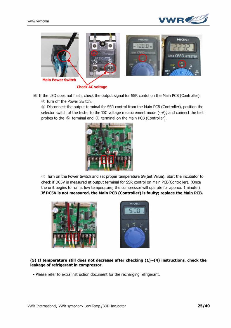
⑥ If the LED does not flash, check the output signal for SSR contol on the Main PCB (Controller).
Turn off the Power Switch.
Disconnect the output terminal for SSR control from the Main PCB (Controller), position the
selector switch of the tester to the ‘DC voltage measurement mode (--V)’, and connect the test
probes to the ⑤ terminal and ⑦ terminal on the Main PCB (Controller).
Turn on the Power Switch and set proper temperature SV(Set Value). Start the incubator to
check if DC5V is measured at output terminal for SSR control on Main PCB(Controller). (Once
the unit begins to run at low temperature, the compressor will operate for approx. 1minute.)
If DC5V is not measured, the Main PCB (Controller) is faulty; replace the Main PCB.
(5) If temperature still does not decrease after checking (1)~(4) instructions, check the
leakage of refrigerant in compressor.
- Please refer to extra instruction document for the recharging refrigerant.
Check AC voltage
① ②
Main Power Switch

www.vwr.com
VWR International, VWR symphony Low-Temp./BOD Incubator 26/40
4. Temperature increases while controller not in operation (1) Check if any temperature SV(Set Value) is set on the controller
- During operation, check ‘Running…’ is displayed on LCD display.
- If any temperature SV(Set Value) is set on controller, press Jog-shuttle to cancel the operation.
(2) If temperature PV(Present Value) on controller increases while the incubator is not in
operation, check the output signal of Heater SSR on the Main PCB (Controller).
① Loosen bolts on top side of the product and detach the upper panel.
② Disassemble the Heater controling terminal on the Main PCB(Controller).
③ Set the Safety Knob to maximum.
④ Turn on only the power switch and do not operate the incubator.
⑤ Check the DC voltage of Heater controling terminal on Main PCB(Controller).
If DC 5 V is measured, replace the Main PCB(Controller). - If DC 5V is not measured, Main PCB is normal; go to next instruction to check if Heater SSR is
damaged.
www.vwr.com
VWR International, VWR symphony Low-Temp./BOD Incubator 27/40
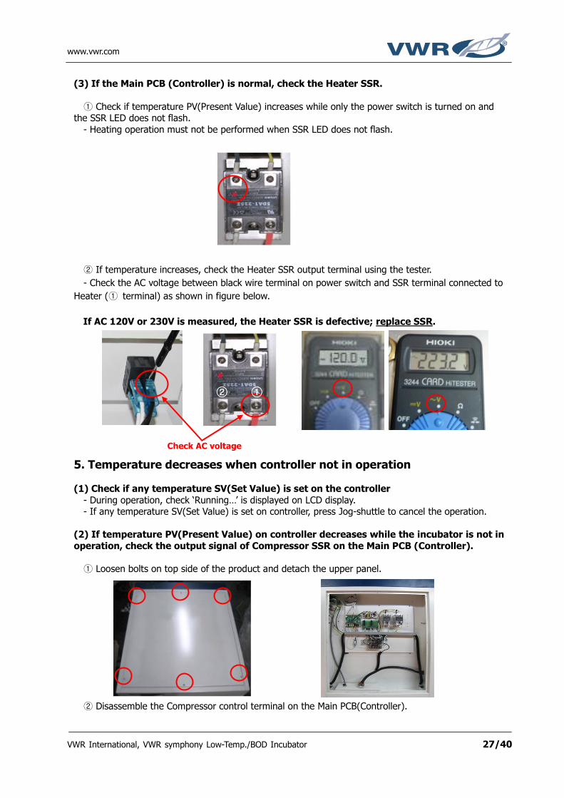
(3) If the Main PCB (Controller) is normal, check the Heater SSR.
① Check if temperature PV(Present Value) increases while only the power switch is turned on and the SSR LED does not flash.
- Heating operation must not be performed when SSR LED does not flash.
② If temperature increases, check the Heater SSR output terminal using the tester.
- Check the AC voltage between black wire terminal on power switch and SSR terminal connected to
Heater (① terminal) as shown in figure below.
If AC 120V or 230V is measured, the Heater SSR is defective; replace SSR.
5. Temperature decreases when controller not in operation
(1) Check if any temperature SV(Set Value) is set on the controller
- During operation, check ‘Running…’ is displayed on LCD display. - If any temperature SV(Set Value) is set on controller, press Jog-shuttle to cancel the operation.
(2) If temperature PV(Present Value) on controller decreases while the incubator is not in
operation, check the output signal of Compressor SSR on the Main PCB (Controller).
① Loosen bolts on top side of the product and detach the upper panel.
② Disassemble the Compressor control terminal on the Main PCB(Controller).
Check AC voltage
① ②

www.vwr.com
VWR International, VWR symphony Low-Temp./BOD Incubator 28/40
③ Turn on only the power switch and do not operate the incubator.
④ Check the DC voltage of Compressor controling terminal on Main PCB(Controller).
If DC 5 V is measured, replace the Main PCB(Controller). - If DC 5 V is not measured, Main PCB is normal; go to next instruction to check if Compressor SSR
is damaged.
(3) If the Main PCB (Controller) is normal, check the Compressor SSR.
① Check if temperature PV(Present Value) decreases while only the power switch is turned on and
the SSR LED does not flash. - Cooling operation must not be performed when SSR LED does not flash.
② If product temperature decreases, check the Compressor SSR output terminal using the tester.
- Check the AC voltage between black wire terminal on power switch and SSR terminal connected to
Compressor(① terminal) as shown in figure below.
If AC 120V or 230V is measured, the Compressor SSR is defective; replace the SSR.
Check AC voltage
① ②

www.vwr.com
VWR International, VWR symphony Low-Temp./BOD Incubator 29/40
6. Large temperature offset (1) Check the Temp. Sensor resistance.
① Loosen bolts on top side of the product and detach the upper panel.
② Disconnect the Temp. Sensor wires from the Main PCB (Controller) terminal block to measure the
resistance of the Temp. Sensor.
③ Select the resistance measurement mode (Ω) on the tester, connect the test probes to the
terminal where the Temp. Sensor was disconnected, and then measure the resistance of the Temp. Sensor.
④ The Temp. Sensor is PT100 and normal resistances at room temperature(20~25) are 104.6
~113.0Ω. If Sensor resistance is abnormal, replace the Temp. Sensor.(Refer to Replacement
Instructions for Key Parts in Section 10.5)
⑤ If Temp. Sensor resistance value is normal, replace the Main PCB.

www.vwr.com
VWR International, VWR symphony Low-Temp./BOD Incubator 30/40
7. Error 1 during operation (1) Error 1 indicates a temperature sensing problem. Check the Temp. Sensor resistance.
① Loosen the bolt on upper side of the product, remove the upper panel, and then disconnect the Temp. Sensor wires from the Main PCB (Controller) to measure the Temp. Sensor resistance.
② Select the resistance measurement mode (Ω) on the tester, connect the test probes to the wires
where the Temp. Sensor was disconnected, and then measure the resistance of the Temp. Sensor.
- The Temp. Sensor is PT100 and normal resistances at room temperature(20~25)
are 104.6 ~113.0Ω. If Sensor resistance is abnormal, replace the Temp. Sensor.(Refer to
Replacement Instructions for Key Parts in Section 10.5) - If Temp. Sensor resistance value is normal, replace the Main PCB(Controller).
8. Error 3 during operation
(1) Error 3 indicates a door open alert. Check the Front Door Limit Switch.
① Check the location of Front Door Limit Switch. - Error 3 is developed if the Limit Switch is not pressed down during product operation.
Open the door and look in the upper left corner. There will be a Limit Switch as shown in the figure
below.
Limit Switch

www.vwr.com
VWR International, VWR symphony Low-Temp./BOD Incubator 31/40
② Loosen the bolt on upper side of the product and detach the upper panel.
③ Disassemble the Limit Switch terminal to check its continuity connection of wires.
- Check the continuity status at terminal of Limit Switch while pressing the Limit Switch. The buzzer
sound in tester should ring at once. - Check the continuity status at the terminal of Limit Switch without pressing the Limit Switch. The
buzzer sound in the tester must not ring at once.
If the Limit Switch is in inoperative condition, replace the Limit Switch. (Refer to
Replacement Instructions for Key Parts in Section 10.4)
If Error 3 continues to occur with no abnormalities of the Limit Switch, replace the Main PCB.
Limit Switch Terminal

www.vwr.com
VWR International, VWR symphony Low-Temp./BOD Incubator 32/40
9. Internal circulation fan is not operative
(1) Check if the Fan is operative.
① Turn the power off, open the front door and loosen up the bolts on the inner chamber.
② Rotate the Fan Motor by hand.
-The Internal circulation Fan is equipped above heater. -If abnormal rotation or noise is observed during rotation of the Fan Motor in the Chamber by hand,
check for any foreign substances in the Fan Motor and then replace the Fan Motor. (Refer to Replacement Instructions for Key Parts in Section 10.6)
③ Check the resistance of Fan.
- Loosen the wires connected to the Fan Motor and check the resistance of Fan as
shown below and if 0 or 0F(infinity) is measured, replace the Fan Motor. (Refer to Replacement Instructions for Key Parts in Section 10.6)
(2) If no abnormalities are inspected in Fan, open the Front Door and check the Limit
Switch.
① Turn on the power switch only, do not set the any temperature.
- Once the power is supplied, the fan motor should operate normally.

www.vwr.com
VWR International, VWR symphony Low-Temp./BOD Incubator 33/40
② Open the door and press the Limit Switch to check the Fan operation.
- The Fan should operate while pressing the Limit Switch.
③ If the Fan is inoperative while pressing Limit Switch, check the connections of the Limit Switch
using tester.
④ Detach the upper panel and disconnect the Limit Switch terminal from the Main PCB(Controller)
and check if the terminal is normal using the tester. - Check the continuity test of Limit Switch.
- If normal, the tester buzzer will sound when the Door is opened; if abnormal, the tester buzzer will not sound when the Door is closed.
-If the Limit switch is faulty, replace it. (Refer to Replacement Instructions for Key Parts in
Section 10.4)
⑤ Check the AC voltage between the black wire terminal on the power switch and Fan output
terminal on Main PCB(controller) after closing the door. - It should measure AC 120V or 230V at those points. If not, replace the Main PCB
(Controller). - If the SSR LED is not illuminated when the door is closed, replace the Main PCB
(Controller).
Limit Switch
Check AC voltage

www.vwr.com
VWR International, VWR symphony Low-Temp./BOD Incubator 34/40
10. Replacement Instructions for Key Parts
(1) How to replace the Heater.
① Loosen the bolt on inside of the chamber and disassemble the panel.
② Disassemble wires from the Heater terminal.
- Loosen the nuts and disassemble wires from the Heater terminal.
③ Heater assembly is conducted in reverse order of disassembly
(2) How to replace the Safety Knob
① Loosen the bolt on back of the product and disassemble the back panel.
- Loosen the bolt on the back and disassemble the back panel.
② Detach the back panel, check the position of the Safety Sensor, and then detach the Sensor.
- Hold and pull the Safety Knob Sensor out from the securing hole.

www.vwr.com
VWR International, VWR symphony Low-Temp./BOD Incubator 35/40
③ Disconnect the Safety Knob terminal mounted on the distribution board.
Disconnect the terminal from the Safety Knob. Pull out the Safety Knob by hand.
④ Safety Knob assembly is conducted in reverse order of disassembly.
(3) How to replace the Safety Protector
① Loosen the bolt on back of the product and disassemble the back panel.
- Loosen the bolt on the back and disassemble the back panel.
② Detach the back panel, check the position of the Safety Sensor, and then detach the Sensor.
- Hold and pull the Safety Knob Sensor out from the securing hole.
Safety Knob Sensor secured position
Safety Knob Sensor secured position

www.vwr.com
VWR International, VWR symphony Low-Temp./BOD Incubator 36/40
③ Open the Distribution Board, disassemble the Safety Protector and replace it.
- Remove the cap of Safety Protector by unscrewing in countclockwise and Unscrew the 2 bolts and nut with using a phillips head screwdriver and spanner
④ Safety Protector assembly is conducted in reverse order of disassembly.
(4) How to replace the Limit Switch
① Open the front door and find the Limit Switch.
② Loosen the bolts and pull out the Limit Switch to replace.
③ Remove the shrink tube and replace the Limit Switch.
④ Limit Switch assembly is conducted in reverse order of disassembly.
Unscrew 2 bolts and nut
Remove the cap of Safety Protector
Limit Switch

www.vwr.com
VWR International, VWR symphony Low-Temp./BOD Incubator 37/40
(5) How to replace the Temp. Sensor
① Loosen the bolt on back of the product and disassemble the back panel.
- Loosen the bolt on the back and disassemble the back panel.
② Open the front door and detach the back panel of inner chamber.
- Loosen the nuts and push out the Temp. Sensor from inside to outside to disassemble.
③ Disassemble the Temp. Sensor wires from Main PCB(Controller) terminal block and replace it.
④ Temp. Sensor assembly is conducted in reverse order of disassembly.
(6) How to replace the Internal Circulation Fan.
① Open the front door and detach the back panel of inner chamber.
Temp. Sensor

www.vwr.com
VWR International, VWR symphony Low-Temp./BOD Incubator 38/40
② Disassemble the wires connected the Fan Motor, loosen up the bolts and replace the Fan Motor.
③ Fan Motor assembly is conducted in reverse order of disassembly.
(7) How to replace the Condenser Motor.
① Loosen up the bolts on the bottom of chamber and detach the panel of compressor deck.
② Disassemble the power supply wires and lossen the nuts to remove the Condenser Motor.
Connector of Power Supply Wire Terminal block of Power Supply
For 414004-626,627,628,629 For 414004-630,631,632,633
Nuts

www.vwr.com
VWR International, VWR symphony Low-Temp./BOD Incubator 39/40
III. Cautions 1. When the product is not used for a long time, unplug and dry the power cord and then package
the product for storage.
2. Use only the genuine parts provided by VWR International if replacement part is necessary due to a product malfunction during use.
3. Any malfunctions caused by using the product outside of VWR recommendations may not be repaired. 4. When cleaning the product, unplug the power cord and clean it with a soft cloth. For a soiled
area not cleaned easily, soak a cloth into fluid with low freezing point and just clean the affected area.
IV. Spare Parts List
VWR Part Number
Description 1 Description 2
414004-871 Main Controller BOD Incubator for all symphony BOD Incubators
414004-875 LCD, 2 Lines, sym incubtr/oven incl. 14P Flat Cable, for all symphony Incubators and Ovens
414004-876 UI Board, S/W sym incbator/ovn incl. 12P Flat Cable, for all symphony Incubators and Ovens
414004-877 Cable, UIBoard,sym incubatr/ovn 12P Flat Cable, all symphony Incubators and Ovens
414004-878 Cable, for LCD and FND Display 14P Flat Cable, all symphony & VWR Incubators and Ovens
414004-888 SMPS, 12V, 0.9A sym BODincbtor for all symphony BOD Incubators
414004-889 SSR, DC/AC SDA1-215Z, for 414004-546~551,553,556~561,563~567,569, 572~575,577~581,583~609,616,617,624~631
414004-891 SSR, DC/AC SDA1-240Z,414004-554,555,570,571, 626~633(for Comp.)
414004-892 SSR, AC/AC SSR-40 AA,414004-554,555,570,571,632,633
414004-894 Safety Knob, 120C/2M for Incubators, 414004-592~597,602~609,614~617,622~633
414004-900 Safety Protector, 80C/2M all incbtr for all symphony & VWR Gravity & Forced Air Incubators,Reach-in Incubators and BOD Incubators
414004-901 Power Switch, Green all symphony & VWR Ovens(except 414004-554,555,570,571) and all symphony & VWR Incubators(except 414004-628,629,630,631,632, 633)
414004-902 Power Switch, Black Circuit Breaker, for 414004-554,555,570,571,628~633
414004-903 Inlet Terminal Block for 414004-554,555,570,571,628~633
414004-906 Fuse, 250V/15A for 414004-550,552,560,562,566,568,574,576,582,596,606,626,627
414004-908 Terminal Block DRT-4.0Q, for all symphony & VWR BOD Incubators,VWR Gravity Convection Ovens and 414004-546~553,568,569,576,577
414004-909 Terminal Block DRT-6.0T,symphony BOD & Reach-in Incubators and 414004-554,555,570,571
414004-910 RS232C Port (D-SUB) all sym for all symphony Ovens and Incubators
414004-911 Door Limit Switch all Incbtors for all symphony & VWR Incubators
414004-914 Temp. Sensor for all symphony & VWR Forced Air Incubators, BOD Incubators, Reach-in Incubators
414004-919 Interal Circulation Fan Motor, 0.26A 120V, for symphony BOD & Reach-in Incubators
414004-920 Interal Circulation Fan Motor, 0.26A 230V, for symphony BOD & Reach-in Incubators
414004-923 Fan Motor, for condensor, 120V, for symphony BOD Incubators
414004-924 Fan Motor, for condensor 230V, for symphony BOD Incubators
414004-941 Heater, 700W, 120V for BOD Incubators, 414004-626
414004-942 Heater, 700W, 230V for BOD Incubators, 414004-627
414004-943 Heater, 1kW, 120V for BOD Incubators, 414004-628
414004-944 Heater, 1kW, 230V for BOD Incubators, 414004-629
414004-945 Heater, 1.2kW, 120V for BOD Incubators, 414004-630
414004-946 Heater, 1.2kW, 230V for BOD Incubators, 414004-631
414004-947 Heater, 2kW, 120V for BOD Incubators, 414004-632
414004-948 Heater, 2kW, 230V for BOD Incubators, 414004-633
Continued in next page

www.vwr.com
VWR International, VWR symphony Low-Temp./BOD Incubator 40/40
VWR Part Number
Description 1 Description 2
414004-971 Cooling Coil 1/2 4 line 3 floor 360, for BOD Incubator, 414004-626,627
414004-972 Cooling Coil 1/2 4 line 3 floor 360, for BOD Incubator, 414004-628,629
414004-973 Cooling Coil 1/2 4 line 3 floor 360, for BOD Incubator, 414004-630,631
414004-974 Cooling Coil 1/2 4 line 3 floor 360, for BOD Incubator, 414004-632,633
414004-975 Compressor, 1/3HP SC10CLX.2, 120V, for BOD Incubator, 414004-626,628
414004-976 Compressor, 1/3HP 230V, for BOD Incubator, 414004-627,629
414004-977 Compressor, 2/5HP SC15CLX.2, 120V, for BOD Incubator, 414004-630
414004-978 Compressor, 2/5HP 230V, for BOD Incubator, 414004-631
414004-979 Compressor, 1/2HP SC18CLS.2, 120V, for BOD Incubator, 414004-632
414004-980 Compressor, 1/2HP 230V, for BOD Incubator, 414004-633
414004-981 Condensor for BOD Incubator, 414004-626,627
414004-982 Condensor for BOD Incubator, 414004-628,629
414004-983 Condensor for BOD Incubator, 414004-630,631
414004-984 Condensor for BOD Incubator, 414004-632,633
414004-985 Solenoid Valve for bypass valve system, all VWR BOD Incubators
414004-986 Refrigerant, 190g for BOD Incubator, 414004-626,627
414004-987 Refrigerant, 290g for BOD Incubator, 414004-628,629
414004-988 Refrigerant, 400g for BOD Incubator, 414004-630,631
414004-989 Refrigerant, 450g for BOD Incubator, 414004-632,633
414004-999 Magnet Packing, 5.3cuft for Incubators, 414004-626,627
414004-1000 Magnet Packing, 9.0cuft for Incubators, 414004-628,629
414004-1001 Magnet Packing, 15.0cuft for Incubators, 414004-630,631
414004-1002 Magnet Packing, 24.7cuft for Incubators, 414004-632,633
414004-1020 Inner Glass Door, 5.3cuft for Incubators, 414004-626,627
414004-1021 Inner Glass Door, 9.0cuft for Incubators, 414004-628,629
414004-1022 Inner Glass Door, 15.0cuft for Incubators, 414004-630,631
414004-1023 Inner Glass Door, 24.7cuft for Incubators, 414004-632,633