VURSA kd, 3-Piece, Center & End Drain Installationsoasisbath.com/documents/INST_0225.08.KD.pdf ·...
7
1 These guidelines are recommended for the proper installation of Oasis products. A careful review of these procedures (and any referenced publications) before starting is important in avoiding an improper assembly and/or installation. NOTE: All illustrations in this publication are typical, and may appear different than the actual product. Optional items may also be shown that were not ordered on the product being installed. Special Notes to Installer u It is the sole responsibility of the installer to determine the requirements necessary for compliance with all installation code require- ments! u All paperwork packaged with the product should be saved and presented to the home owner upon completion of the installation! u All published product dimensions are for reference only. Any critical dimensions required for installation should be taken directly from the product being installed! u Any independent modifications made to the product (or any options / accessories supplied) beyond those required for normal installation can void all warranties! (Refer to warranties for further information) INSPECTION GUIDELINES Carefully check the unit upon receipt. Notify your supplier immediately if any questions or problems are encountered during this process. DO NOT INSTALL PRODUCT WITHOUT FIRST ADDRESSING QUESTIONS WHICH ARISE DURING THE INSPECTION! Basic Module Check l Check unit drain position for match to bathroom drain location. l Check unit for surface damage. l Check wall section(s) and base for color match. l Check unit color for coordination to other bathroom fixtures. INSTALLATION SITE FRAMING The recommended framing and dimensional requirements shown are for a traditional application and may vary, based on site requirements. The dimensions shown in the dimensional diagram(s) are from the surfaces where the unit will be attached. This surface can be bare studding, dry wall or other suitable un- der layment material. It is important that the floor and all framing be square, plumb and level. Framing must be done using accepted materials and construction techniques in accordance with all applicable codes for the site. NOTE: Any pre-constructed wall(s) may require modification or additional framing to allow for factory applied pipes and/or fittings which may protrude from the body of the unit. NOTE: A minimum of 48-inches of drywall must be removed from the framing area in order to place the components in the alcove. INSTALLATION PROCEDURE NOTE: ‘Wet-set’ is not required to support the floor under an Oasis product due to the encapsulated Balsa wood construction. The VURSA kd, multi-piece system is de- signed as a front side installation procedure, with three (3) individual sections locking securely together. ® VURSA kd, 3-Piece, Center & End Drain Installations Tub/Showers: TS3P-6030 (all versions) TS3P-6032 (all versions) Showers: SH3P-3232 (all versions) SH3P-3636 (all versions) SH3P-4832 (all versions) SH3P-4834 (all versions) SH3P-6030 (all versions) SH3P-6032 (all versions) SH3P-4834LS ABF (shown) SH3P-6032L-RS ABF (shown) TS3P-6032L ABF (shown) TS3P-6030R ABF (shown) SH3P-6030R-LS ABF (shown) SH3P-3232 (shown) SH3P-3636 (shown) SH3P-4832 (shown)
Transcript of VURSA kd, 3-Piece, Center & End Drain Installationsoasisbath.com/documents/INST_0225.08.KD.pdf ·...
1
These guidelines are recommended for the proper installation of Oasis products. A careful review of these procedures (and any referenced publications) before starting is important in avoiding an improper assembly and/or installation.
NOTE: All illustrations in this publication are typical, and may appear different than the actual product. Optional items may also be shown that were not ordered on the product being installed.
Special Notes to Installeru It is the sole responsibility of the installer to determine the requirements necessary for compliance with all installation code require-ments!
u All paperwork packaged with the product should be saved and presented to the home owner upon completion of the installation!
u All published product dimensions are for reference only. Any critical dimensions required for installation should be taken directly from the product being installed!
u Anyindependentmodificationsmadetothe product (or any options / accessories supplied) beyond those required for normal
installation can void all warranties! (Refer to warranties for further information)
INSPECTION GUIDELINES
Carefully check the unit upon receipt. Notify your supplier immediately if any questions or problems are encountered during this process.
DO NOT INSTALL PRODUCT WITHOUT FIRST ADDRESSING
QUESTIONS WHICH ARISE DURING THE INSPECTION!
Basic Module Checkl Check unit drain position for match to
bathroom drain location.l Check unit for surface damage.l Check wall section(s) and base for color
match.l Check unit color for coordination to other
bathroomfixtures.
INSTALLATION SITE FRAMING
The recommended framing and dimensional requirements shown are for a traditional application and may vary, based on site requirements.
The dimensions shown in the dimensional diagram(s) are from the surfaces where the unit will be attached. This surface can be bare studding, dry wall or other suitable un-der layment material. It is important that the floorandallframingbesquare,plumbandlevel. Framing must be done using accepted materials and construction techniques in accordance with all applicable codes for the site.
NOTE: Any pre-constructed wall(s) may requiremodificationoradditionalframingtoallowforfactoryappliedpipesand/orfittingswhich may protrude from the body of the unit.
NOTE: A minimum of 48-inches of drywall must be removed from the framing area in order to place the components in the alcove.
INSTALLATION PROCEDURE
NOTE: ‘Wet-set’ is not required to support thefloorunderanOasisproductduetotheencapsulated Balsa wood construction.
The VURSA kd, multi-piece system is de-signed as a front side installation procedure, with three (3) individual sections locking securely together.
®
VURSA kd, 3-Piece, Center & End Drain Installations
Tub/Showers: TS3P-6030 (all versions) TS3P-6032 (all versions)
Showers: SH3P-3232 (all versions) SH3P-3636 (all versions) SH3P-4832 (all versions) SH3P-4834 (all versions) SH3P-6030 (all versions) SH3P-6032 (all versions)
SH3P-4834LS ABF (shown) SH3P-6032L-RS ABF (shown)
TS3P-6032L ABF (shown)TS3P-6030R ABF (shown)
SH3P-6030R-LS ABF (shown)
SH3P-3232 (shown)SH3P-3636 (shown)
SH3P-4832 (shown)

2
Illustrations 1a - Center Drain, Unit Dimension & Alcove Framing Guidelines (dimensional tolerance +0 / -3/8”)
71-1/2”
26-3/4”
1-1/4”
26-3/4”
18-1/2”Seat
53-1/2”
ContouredSeat
Toe Hold
18”
Shelf
AccessoryLedge
Ledge
Shelf
Shelf
48”
1-3/4”
1-1/4”
Back Wall
1-3/4” 44-1/2”
24” 24”
Drip Ledge
17-1/8”
34”
35-1/4”
16-7/8” ContouredSeat
3-3/8” Dia.Drain
AccessoryLedge
ShelfShelf
Dam
Drain ClearanceD
C
B
A
F
Seam
Seam
Std Unit ABF UnitA 76-3/4” 78-3/4”B 75-1/2” 77-1/2”C 4” 6”D 1” 3”E - -F 22” 24”
SH3P-4834RS (illustr.)
1-11/16”
16”
32”
33-1/4”
1-1/4”
16”
71”
1-11/16”
1-1/4”
25-1/2”
1-1/4”
20”
25-1/2”
32”
Back Wall
28-5/8”
16” 16”
Drip Ledge
Seam
Seam
8”w x 2-3/4”d Shelves
3-3/8” Dia.Drain
Shelves
Drain ClearanceD
DamC
B
A
F
DamC
1-11-16”
18”
36”
37-1/4”
1-1/4”
18”
1-1/4”
70-3/4”
Back Wall
Seam
25-1/2”
1-1/4”
Seam
25-1/2”10”w x 3”d
Shelves
4”w x 4”dAccessory
Ledges
36”
1-11/16” 32-5/8”
18” 18”
Drip Ledge
3-3/8” Dia.Drain
Shelves
Accessory Ledges
B
F
Drain ClearanceD
A
vStd Unit ABF UnitA 76” 78”B 74-3/4” 76-3/4”C 4” 6”D 1” 3”E - -F 23-3/4” 25-3/4”
SH3P-3636 ABF (illustr.)
Std Unit ABF UnitA 76-1/4” 78-1/4”B 75” 77”C 4” 6”D 1” 3”E - -F 24” 26”
SH3P-3232 ABF (illustr.)
71-1/4”
26-3/4”
1-1/4”
26-3/4”
1-1/4”
16”w x 3”dShelves
48”
1-3/4”
1-1/4”
1-3/4” 44-1/2”
24” 24”
Drip Ledge
16”
32”
33-1/4”
16”3-3/8” Dia.
Drain
Shelves
Drain ClearanceD
DamC
B
A
F
Back Wall
Seam
6” x 4”Accessory
Ledges
Std Unit ABF UnitA 76-1/2” 78-1/2”B 75-1/4” 77-1/4”C 4” 6”D 1” 3”E - -F 21-3/4” 23-3/4”
SH3P-4832 ABF (illustr.)

3
Factory-installed pegs have been positioned on the top ledge of the base and mid- section components, and align with holes on the underside of the mid and top-sections. Eachholehasbeenfittedwithauniqueconnector which locks to the peg.
The connection process provides an audible “CLICK” when each peg and insert are mated, resulting in compression along the seam.
WARNING: Alcove framing members cannot tilt, angle or protrude into the area intended for the three (3) individual unit sections to occupy, as this can compromise proper alignment of the VURSA kd sections.
1a. Position the base component in the framed area. Before attaching the base sec-tion to the framing, a series of details must be checked (photo 1).
l Confirmthelowerapron/damisrestingflushonthefloor.
l Confirmthebasecomponentislevelalong the back, the front and ends.
l Confirmthebasecomponentisposi-tioned square in the framed area.
l Confirmthebasecomponentisposi-tioned plumb in the framed alcove.
l Confirmthedrainholeposition.
SPECIAL NOTE: Move base section forward within alcove by applying 1/8”-thick shims behind attachment flange across entire back wall.
NOTE: Use of additional shims behind the attachmentflangesmayberequiredtoen-sure the base component remains square, and plumb in the framed area. Caution must be used to avoid distorting the unit shape, which can compromise proper alignment of the VURSA kd sections.
THE BASE MUST BE LEVEL, SQUARE AND PLUMB TO INSURE PROPER FIT
OF THE UPPER SECTIONS!
1b. With the base component correctly positioned, drill a 1/8” hole through the
flangeateachframingmember.Attachtheflangeacrossthebackfirst,followedbythe ends and then along the front vertical flanges,using1-1/4”longnailsorotherappropriatefasteners,approximately7”-9”apart. Continually check to make sure the base component remains square and plumb within the framed area as it is being secured to ensure proper alignment for the upper sections (photo 2).
NOTE: Usage of a thin shield to protect the unit surface while fastening it to the framing is recommended.
WARNING!THE BASE COMPONENT FLOOR
SHOULD BE CLEAR OF ALL LOOSE DEBRIS AND THE SURFACE
PROTECTED BEFORE STEPPING INSIDE.
2a. With the base component securely at-tachedtotheframing,dry-fitthemid-sectiontoconfirmproperalignment,andidentifyany required shim adjustments necessary for the base component.
Toperformthedry-fitprocedure,positionthe mid-section above the pegs on the base component with the front edge overhanging the base about 2-inches. Apply even pres-sure to the front of the mid-section on both sides, moving it back across the top of the pegs (photo 3). When properly positioned the base component pegs enter holes along
FixtureBlocks
Drain Cut-Out
Photo 1
1/8” Shims behind back wall mounting flange(basesectiononly)
Model 01 02 03 04 05a 05b 06a 06b 07 08SH3P-3232 32” 33-1/4” 32” 16” 16” 16” 13-1/2” 13-1/2” 13-1/2” 13-1/2”SH3P-3636 36” 37-1/4” 36” 18” 18” 18” 15-1/2” 15-1/2” 15-1/2” 15-1/2”SH3P-4832 48” 33-1/4” 32” 16” 24” 24” 21-1/2” 21-1/2” 13-1/2” 13-1/2”SH3P-4834 48” 35-1/4” 34” 17-1/8” 24” 24” 21-1/2” 21-1/2” 14-5/8” 14-3/8”
5“
04
02Minimum
Alcove Depth,Unit Rough-In
Depth
DrainCut-Out
DrainCenter
07
08
01Alcove Length - Unit Width
03Finished
Unit Depth
06a 06b
05a 05b
5“
Illustrations 1a - Center Drain, Unit Dimension & Alcove Framing Guidelines (dimensional tolerance +0 / -3/8”)
4
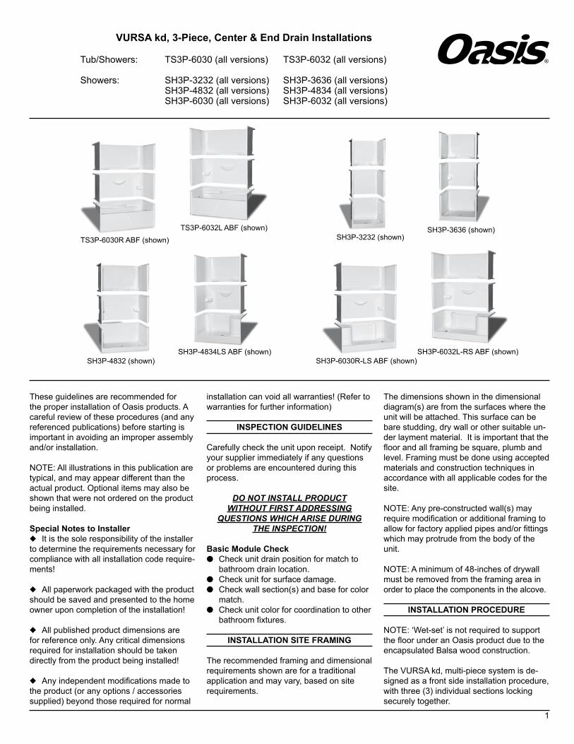
the underside of the mid-section ledge and ‘CLICK’inplaceconfirmingapositivecon-nection. With the mid-section fully seated, confirmpropermatingandseamalignmentwith the base component at the front face and across the inner sidewalls.
NOTE: The VURSA kd back wall uses offset face contouring to direct water away from theseam,intentionallyeliminatingflushfacealignment along the back wall seam.
2b.Withproperalignmentconfirmed,liftthe mid-section off the base and out of the alcove area. Thoroughly clean the mating
surfaces on both the base component and the mid-section.
NOTE: Oasis recommends a high qual-ity silicone based sealant with a mold and mildew resistant content.
ApplyaSMALL(approximately1/8-inchwide - photo 4) continuous bead of sealant on the top ledge of the base component, beginningattheattachmentflangeatthefirstpeg,alonganimaginarylinefrompeg-to-peg on the shower side (photo 5). At the frontcorners,extendthebeadatthebaseof the front peg to the front and back to the faceoftheattachmentflange.(photo6).
Drain ClearanceD
C
B
A
F
E
60-1/4”
1-1/4”Back Wall1-1/4”
26-3/4”
26-3/4”
Shelf
AccessoryLedge
Shelf
Shelf
Shelf
51”
30”
31-1/4”
1-1/4”
1-5/8”
14-1/4”
15-3/4”
60”
1-5/8” 56-3/4”
9”
2-1/2” Dia. Overflow
2” Dia. Drain
Shelf Shelf
Shelf
B
C
3“ Drain ClearanceD
F
A
51”
30”
31-1/4”
1-1/4”
26-3/4”
1-1/4”
26-3/4”
1-5/8”
14-1/4”
15-3/4”
60”
1-5/8”
Back Wall
56-3/4”
1-1/4”
9”
71-1/2”
Shelves
AccessoryLedge
Shelf
Ledge
3-3/8” Dia. Drain
Shelf Shelf
Shelf
ContouredSeat
Toe Hold
18-1/2”Seat
Drain Cut-Out
5“
14-1/4”
31-1/4”Minimum
Alcove Depth,Unit Rough-In
Depth
Drain
Center9”
DrainCenter
11-1/2”11-3/4”
13-1/4”
30”Finished
Unit Depth
60”Alcove Length - Unit Width
NOTE: Left End Drain Installation Illustrated.
21“ WidePump
Access ForTS3P-6030
WithWhirlpool
FixtureBlocks
Drain Cut-Out
21" W x 16" HPump AccessMANDATORY
on All WhirlpoolEquipped Units
Illustration 1b - End Drain, Unit Dimension & Alcove Framing Guidelines (dimensional tolerance +0 / -3/8”)
Photo 2
Base Unit ABF UnitA 77-1/2” 78-3/4”B 76-1/4” 77-1/2”C 16” 17-1/4”D 1-3/4” 3”E 13-3/4” 15”F 22-3/4” 24”
TS3P-6030L (illustr.)
Std Unit ABF UnitA 76-3/4” 78-3/4”B 75-1/2” 77-1/2”C 4” 6”D 1” 3”E - -F 22” 24”
SH3P-6030R-LS (illustr.)

5
WARNING!DO NOT APPLY SEALANT ON THE TOP
OF ANY PEGS AS IT WILL COMPROMISE THE LOCKING CONNECTION.
(Silicone ribbons enhanced for photo visibility.)
Carefully reposition the mid-section over the pegs on the base component and listen for theaudible‘CLICK’toconfirmtheconnec-tion.Removeanyexcesssiliconefromtheseam at this time.
2c. Secure the mid-section by drilling a 1/8” holethroughtheattachmentflangeateach
framingmemberandapproximatelyevery7”-9”alongtheverticalflanges.Continuallycheck to make sure the horizontal seam remains tight as the mid-section is being attached to the framing (photo 2).
NOTE: The use of shims behind the at-tachmentflangemayberequiredtoensurethe mid-section remains properly aligned vertically. Caution must be used to avoid distorting the unit shape, which can affect top-section alignment.
3. With the mid-section securely attached to theframing,repeatthedry-fitprocesswith
Photo 3
Drain Cut-Out
5“
16-1/4”
33-1/4”Minimum
Alcove Depth,Unit Rough-In
Depth
Drain
Center9”
DrainCenter
11-1/2”13-3/4”
13-1/4”
32”Finished
Unit Depth
60”Alcove Length - Unit Width
NOTE: Left End Drain Installation Illustrated.
21“ WidePump
Access ForTS3P-6032
WithWhirlpool
FixtureBlocks
Drain Cut-Out
21" W x 16" HPump AccessMANDATORY
on All WhirlpoolEquipped Units
1-5/8”
1-1/4”
32”
33-1/4”
1-1/4”
16-1/4”
15-3/4”
60”
Back Wall
56-3/4”
1-1/4”
1-5/8”
9”51”
26-3/4”
26-3/4”
71-1/2”
Dam
18-1/2”Seat
3-3/8” Dia. Drain ContouredSeat
Shelf Shelf
Shelf
ContouredSeat
Ledge
Shelf
AccessoryLedge
Shelf
Shelf
Toe Hold
Drip Ledge
Drain ClearanceD
C
F
A
B
1-5/8”
32”
33-1/4”
1-1/4”
60-1/4”
1-1/4”
16-1/4”
15-3/4”
60”
Back Wall
56-3/4”
1-1/4”
1-5/8”
9”51”
Shelf Shelf
Shelf2-1/2” Dia. Overflow
2” Dia. Drain
26-3/4”
26-3/4”
Shelf
AccessoryLedge
Shelf
Shelf
Shelf
Drip Ledge
Drain ClearanceD
C
B
A
F
E
Illustration 1c - End Drain, Unit Dimension & Alcove Framing Guidelines (dimensional tolerance +0 / -3/8”)
Base Unit ABF UnitA 77-1/2” 78-3/4”B 76-1/4” 77-1/2”C 16” 17-1/4”D 1-3/4” 3”E 13-3/4” 15”F 22-3/4” 24”
TS3P-6032R (illustr.)
Std Unit ABF UnitA 76-3/4” 78-3/4”B 75-1/2” 77-1/2”C 4” 6”D 1” 3”E - -F 22” 24”
SH3P-6032R-LS (illustr.)

6
thetop-sectiontoconfirmproperalignment,and identify any shim adjustments required to the mid-section. (Refer to and follow steps 2a, 2b and 2c for detailed instructions, and supporting notes to complete the as-sembly of the top-section.)
Water Supply and Drain ConnectionsRefer to, and follow, the assembly and installation instructions provided with the supply valves and drain system. Carefully check all connections for leaks.
Finishing GuidelinesFillerstripsorfillermaterialmayberequiredover the framing to ensure the under lay-mentmountsflushovertheflanges.Awaterresistant under layment is recommended surrounding the unit. Stop the under lay-ment 1/16 to 1/8-inch from the unit surface, andfillthespacewithacontinuousbeadofwater resistant sealant (illust. 2).
Use care when fastening the under layment near the unit surface to avoid damage. Seal the under layment seams and edges, as required,andinstallthefinishmaterialtospecifications.
UNIT SURFACE CARE
WARNING!NEVER USE ABRASIVE MATERIALS,
OR ABRASIVE CLEANERSON THE UNIT SURFACE!
EXTREME CAUTION is urged regarding the use of any cleaner, acid or solvent
on the unit surface.
READ AND FOLLOW PACKAGE INSTRUCTIONS FOR ALL
PURCHASED CLEANING PRODUCTS!
Through routine use, the unit surface can collect residues from soap, bath additives and natural body oils. Additional deposits can also collect from minerals or particles found in the water. After each use, wipe the excesswaterfromtheunit.Thispracticewill reduce the buildup of deposits and help maintain the natural unit lustre.
Following a thorough surface cleaning, anapplicationofqualityautomotivewaxwill help reduce major accumulations. The actualscheduleforcleaningandwaxingwilldepend on unit usage and water quality.
WARNING!NEVER APPLY WAX
TO THE UNIT FLOOR!
u Routine Cleaning: Mild, non-abrasive cleanerspecificallyformulatedforgelcoatand acrylic surfaces recommended. (Rinse surface thoroughly)
u Heavy Soap Deposits: Liquid ammonia household cleaner, applied full strength. (Rinse surface thoroughly)
u Stubborn Stains: Liquid household cleanerorhydrogenperoxideappliedfull strength. Place a saturated clean rag directly on stain and let stand several hours. (Rinse surface thoroughly)
u Hard Water Scales: Liquid scale remover or white vinegar, applied full strength. (Rinse surface thoroughly)
u Mold/Mildew: Liquid mildew remover or baking soda and water paste. (Apply paste andallowtofizzseveralminutes.)(Rinsesurface thoroughly)
u Construction Adhesive: Soften adhesive with a hand held hair dryer and peel off adhesive. (Caution is advised when using any electrical device near water.)
For adhesive residue, apply rubbing alcohol or nail polish remover, full strength. (Rinse surface thoroughly)
WARNING!BATH MATS AND OTHER ITEMS HELD IN
PLACE USING SUCTIONSMUST BE REMOVED FROM THE UNIT
SURFACE AFTER EACH USE.
OVER AN EXTENDED PERIOD, FAILURE TO REMOVE
SUCTION ATTACHED ITEMS WILL DAM-AGE THE UNIT SURFACE.
Photo 5
Photo 4
Photo 6
Water ResistantUnderlayment
WaterproofSealant
Furring Strip orShim Material
NailingFlange
Wall Framing
Illustration 2 - Wall Finishing
Apply silicone bead to the interior side of pegs.
Oasis Lifestyle, LLC - 1400 Pidco Drive - Plymouth, Indiana 46563
Oasis Lifestyle Product Assurance Program
Bathing and Shower Unit Structure & Surface Finish Limited WarrantyOasisLifestyleprovidesaperformanceassuranceprogramforunitstructuralintegrityandsurfacefinishcoveringafive(5) year period from the date-of-purchase on GELCOAT, and covering a ten (10) year period from the date-of-purchase on VACUUM FORMED ACRYLIC product, for the original purchaser and subsequent consumer. This Oasis limited warranty pro-gramaddressesspecificdefectsintheproduct,andtheworkmanshipassociatedwiththemanufactureoftheOasisbathingandshowerproduct.Thespecificdefectscoveredmustresultinasignificantlyalteredappearanceand/oraffecttheintendedperformance standards for the product under normal residential use.
Hydro-Massage Systems (water recirculation & air), Option & Accessories Limited WarrantyOasis Lifestyle provides a performance assurance program for their hydro-massage systems (herein called ‘system’), and their options and accessories covering a two (2) year period from the date-of-purchase for the original purchaser and subse-quentconsumer.ThisOasislimitedwarrantyprogramaddressesspecificdefectsinthesystemcomponents,andthework-manship associated with the assembly of the systems, along with offered options and accessories installed by Oasis, on an Oasisunit.Thespecificdefectscoveredmustresultinasignificantlyalteredappearanceand/oraffecttheintendedperfor-mance standards for the system, the option and/or the accessory.
Duringthecoverageperiod,Oasiswill,atitsdiscretion(followingaverificationbyanauthorizedOasisrepresentative),eitherprovideserviceorsupplyareplacementproductwithoutcharge,butexcludinganycostassociatedwiththetransportation,removal of and/or reinstallation of the unit (module). Failure to allow requested inspection by an authorized Oasis representa-tive, and/or failure to provide adequate accessibility for an authorized inspection, and/or service performed prior to document-ed authorization from Oasis Lifestyle, LLC., may delay service, and/or possibly terminate any warranty coverage, and remove any liability to Oasis Lifestyle, LLC.
This ‘Product Assurance Program’ does not cover service resulting the following:a) Improperfieldinstallationoftheproduct,system,option,accessory,and/orsurroundingstructure
modifications,and/orutilityserviceconnectionsbeyondtherecommendationssuppliedbyOasisandwithinthescope of applicable codes and ordinances; or
b) Carelessness,damage,abuse,misuse,negligence,impropercare,fire,flood,oractsofGod;orc) Non-conforming use, including any use beyond those intended for the product, system, option and/or
accessory, including failure to follow the Prescribed Care and Maintenance Instructions; ord) Anyunauthorizedalterationsormodificationstotheproduct,system,option,accessoryand/ortheindividual
parts or components supplied by Oasis.e) Any surface and/or component staining, discoloration, component failure and/or build-up caused as a result of
water chemistry or water quality at the site.f) Service resulting from normal use and wear for the product, system, option and/or accessory.
Repairorthesupplyingofreplacementproductand/orcomponents,underthislimitedwarrantyprogram,shallbetheex-clusive remedy. Oasis Lifestyle, LLC., shall not be liable for any incidental or consequential damages, including damages to thebuilding/structure,thecontents,theoccupants,orbreachofanyexpressedorimpliedwarranties.OasisLifestyle,LLC.,does not recognize, nor authorizes any party to provide implied or written warranties regarding a product, system, option and/oraccessoriesfitnessforaparticularpurpose,normodifythetermsofthelimitedwarrantybeyondthosestated.
Somestatesdonotallowtheexclusionorlimitationofincidentalorconsequentialdamages,orallowlimitationsonthedura-tionofanyimpliedwarranty.Therefore,theaboveexclusionsand/orlimitationsmaynotapply.
THIS WARRANTY PROVIDES SPECIFIC LEGAL RIGHTS, WHICH CAN VARY FROM STATE-TO-STATE.
800.638.8556HomeInnovation.com
The manufacturer represents that the product to which this label is affixed (a) duplicates samples independently tested by Home Innovations Research Labs and certified to conform to the requirements of HUD UM Bulletin 73a and the appropriate ANSI Z124 and ICC/ANSI A117.1 standards, and (b) has been manufactured under quality controls deemed appropriate by the manufacturer and periodically reviewed by the certifier.
Oasis Lifestyle, LLCPlymouth, IN
6006
800.638.8556HomeInnovation.com
The manufacturer represents that the product to which this label is affixed (a) duplicates samples independently tested by Home Innovations Research Labs and certified to conform to the requirements of HUD UM Bulletin 73a and the appropriate ANSI Z124 and ASME A112.19.7 standards, and (b) has been manufactured under quality controls deemed appropriate by the manufacturer and periodically reviewed by the certifier.
Oasis Lifestyle, LLCPlymouth, IN
6006
®
7INST-0225.08 / 031717


![KD-X470BHS / KD-X370BTS / KD-X37MBS / KD-X270BT ...Data Size: B6L (182 mm x 128 mm) Book Size: B6L (182 mm x 128 mm) ENGLISH FRANÇAIS ESPAÑOL B5A-3105-00a [K] KD-X470BHS / KD-X370BTS](https://static.fdocuments.us/doc/165x107/5fa2da61a08b9c64377c7b40/kd-x470bhs-kd-x370bts-kd-x37mbs-kd-x270bt-data-size-b6l-182-mm-x-128.jpg)