
VT1 ECU PROGRAMMER USER MANUAL - Athena · PDF fileManuale Utente PROGRAMMATORE VT1 rev. 02...
32
ENGLISH By Athena Evolution VT1 ECU PROGRAMMER USER MANUAL
Transcript of VT1 ECU PROGRAMMER USER MANUAL - Athena · PDF fileManuale Utente PROGRAMMATORE VT1 rev. 02...

EN
GLI
SH
By Athena Evolution
VT1 ECU PROGRAMMER
USER MANUAL
Manuale Utente PROGRAMMATORE VT1 rev. 02
Copyright ©2011 GET by Athena Evolution s.r.l. Tutti i diritti riservati
EN
GLIS
H
VT1 User Manual release 02
Release FW 1.2 Copyright © 2011 GET by Athena Evolution. All right reserved.
The content of this document, part of this document, could be copied, transferred, send or memorized on other form without the written consent of GET by Athena Evolution s.r.l.
GET has the right to change without notice the content of this manual.

Manuale Utente PROGRAMMATORE VT1 rev. 02
Copyright ©2011 GET by Athena Evolution s.r.l. Tutti i diritti riservati
1
EN
GLI
SH
INDEX 1 VT1 KIT ................................................................................................................................................... 2 2 MAIN FUNCTIONS AND CARACTERISTICS ........................................................................................ 3 3 CORRECT USE ...................................................................................................................................... 3 4 WARNING ............................................................................................................................................... 3 5 VT1 CONNECTION TO ECU .................................................................................................................. 4 6 BATTERY LESS VEHICLE CONNECTION ............................................................................................ 5 7 VT1 CONNECTION TO LC1 EVO MODULE .......................................................................................... 6 8 VT1 CONTROLLS AND SIGNALS .......................................................................................................... 7 8.1 VT1 BUTTON USE .................................................................................................................................. 7 8.2 SWITCH ON ............................................................................................................................................ 7 9 VT1 PAGES, MENU AND FUNCTION.................................................................................................... 8 9.1 MAIN PAGE ............................................................................................................................................. 8 9.2 SHOW LAMBDA MENU .......................................................................................................................... 9 9.3 CONFIG ECU MENU ............................................................................................................................ 10 9.4 OPTIONS MENU ................................................................................................................................... 11 10 HOW TO …. .......................................................................................................................................... 12 10.1 TPS CALIBRATION............................................................................................................................... 12 10.2 INJECTED FUEL QUANTITY ADJUSTMENT ...................................................................................... 14 10.3 TIMING ADVANCE ADJUSTMENT ...................................................................................................... 15 10.4 RPM LIMITER ADJUSTMENT .............................................................................................................. 16 10.5 CUTOFF ADJUSTMENT ....................................................................................................................... 17 10.6 GPA (Get Power Assistance) ADJUSTMENT ....................................................................................... 18 10.7 LAMBDA SENSOR AIDED MIXING CHECK ........................................................................................ 19 10.8 ORIGINAL ECU VALUES RESTORE ................................................................................................... 21 10.9 ECU PARAMETER VISUALIZATION ................................................................................................... 23 11 ECU COMPATIBILITY LIST .................................................................................................................. 24 11.1 ADJUSTMENT RANGE ........................................................................................................................ 24 12 FIRMWARE UPDATE ........................................................................................................................... 25 13 TROUBLESHOOTING .......................................................................................................................... 27 14 TECHNICAL SPECIFICATION ............................................................................................................. 27 Dear customer, Thank you for choosing a product from DATA ACQUISITION AND ANALYSIS SYSTEMS by GET by Athena Evolution range. We are confident that our passion and experience will help you to express yourself successfully in all competition. We whish to invite you to read carefully this user manual that will help you on the use of this new GET by Athena Evolution product. VT1 permit to visualize and/or change some base parameters stored in linked ECU. The simply use of this product (VT1 may need the use of a pc) make the VT1 important and useful during workshop job and during testing and racing. In this manual ECU means Electronic Control Unit. This is referred to engine injection control unit. * ECU list is inside this manual.

Manuale Utente PROGRAMMATORE VT1 rev. 02
Copyright ©2011 GET by Athena Evolution s.r.l. Tutti i diritti riservati
2
EN
GLIS
H
1 VT1 KIT VT1 is supplied with: • box • VT1 • CD with software and various documents
DO NOT OPEN THE PRODUCT UNSCREWING THE SCREWS UNDER THE BATTERY COMPARTMENT. THE OPENING WILL BE VISUALIZED WITH THE BREAKING OF INTERNAL SEALS. THIS WILL VOID THE WARRANTY.
Manuale Utente PROGRAMMATORE VT1 rev. 02
Copyright ©2011 GET by Athena Evolution s.r.l. Tutti i diritti riservati
3
EN
GLI
SH
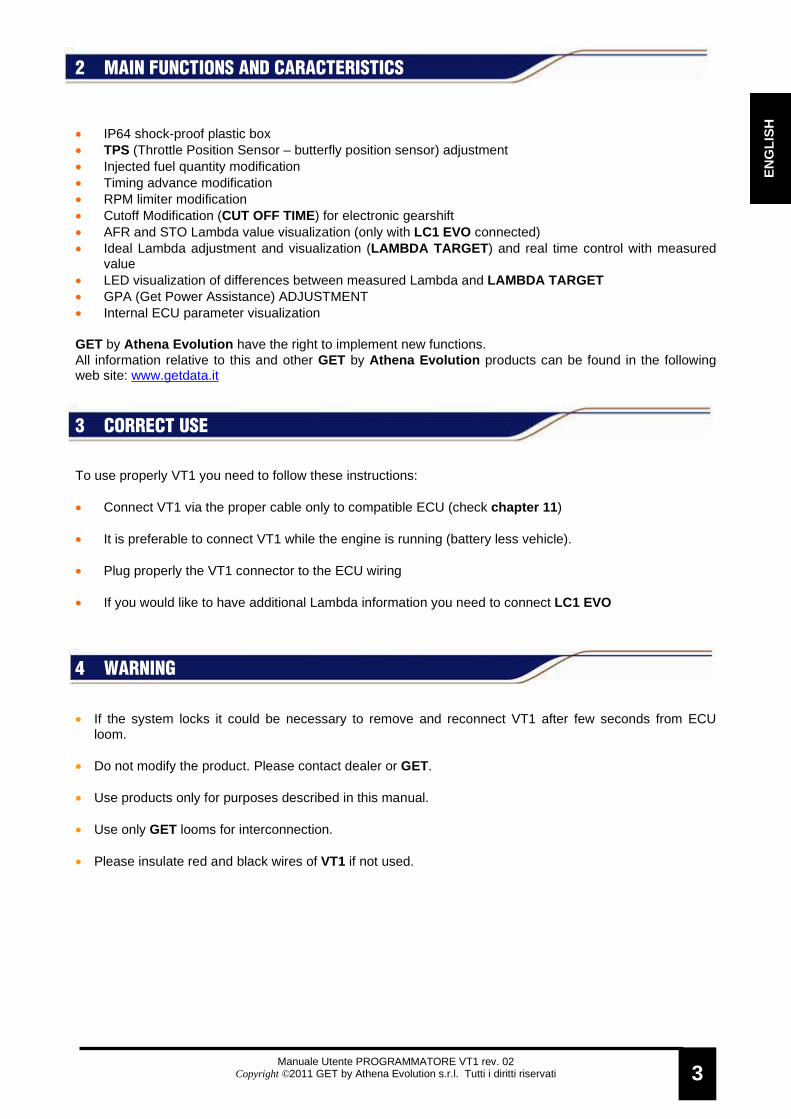
2 MAIN FUNCTIONS AND CARACTERISTICS • IP64 shock-proof plastic box • TPS (Throttle Position Sensor – butterfly position sensor) adjustment • Injected fuel quantity modification • Timing advance modification • RPM limiter modification • Cutoff Modification (CUT OFF TIME) for electronic gearshift • AFR and STO Lambda value visualization (only with LC1 EVO connected) • Ideal Lambda adjustment and visualization (LAMBDA TARGET ) and real time control with measured
value • LED visualization of differences between measured Lambda and LAMBDA TARGET • GPA (Get Power Assistance) ADJUSTMENT • Internal ECU parameter visualization GET by Athena Evolution have the right to implement new functions. All information relative to this and other GET by Athena Evolution products can be found in the following web site: www.getdata.it
3 CORRECT USE To use properly VT1 you need to follow these instructions: • Connect VT1 via the proper cable only to compatible ECU (check chapter 11)
• It is preferable to connect VT1 while the engine is running (battery less vehicle).
• Plug properly the VT1 connector to the ECU wiring
• If you would like to have additional Lambda information you need to connect LC1 EVO
4 WARNING
• If the system locks it could be necessary to remove and reconnect VT1 after few seconds from ECU loom.
• Do not modify the product. Please contact dealer or GET. • Use products only for purposes described in this manual. • Use only GET looms for interconnection. • Please insulate red and black wires of VT1 if not used.

Manuale Utente PROGRAMMATORE VT1 rev. 02
Copyright ©2011 GET by Athena Evolution s.r.l. Tutti i diritti riservati
4
EN
GLIS
H
Programming and data connection
5 VT1 CONNECTION TO ECU VT1 can be linked to ECU via a specific loom from the rear part of the instrument. The connection could be done as follow: • Direct link via the PROGRAM/DATA ECU loom
• Link with MULTILINK loom (part number GL-0018-AA )
NOTE: VT1 WILL SWITCH ON AUTOMATICALLY ONCE ECU IS POWERED. THIS OPERATION WILL NEED FEW SECONDS. All previous connections are available for all vehicles. It is not possible to switch on the system with no battery and with engine NOT RUNNING. For this option, please read next chapter.
WARNING: THIS HARDWARE CONNECTION REQUIRE ELECTRI CAL INSULATION FOR RED AND BLACK WIRES TO PREVENT POWER SUPPLY S HORT CIRCUIT
WARNING: THIS HARDWARE CONNECTION REQUIRE ELECTRI CAL INSULATION FOR RED AND BLACK WIRES TO PREVENT POWER SUPPLY S HORT CIRCUIT
DATALOGGER (OPTIONAL)
Programming and data connection
GL-0018-AA (multi-link loom)

Manuale Utente PROGRAMMATORE VT1 rev. 02
Copyright ©2011 GET by Athena Evolution s.r.l. Tutti i diritti riservati
5
EN
GLI
SH
6 BATTERY LESS VEHICLE CONNECTION
If a connection to a battery less vehicle is needed with the engine NOT RUNNING it is necessary to use and external power supply. With the use of red (positive) and black (negative) wires it is possible to switch on the VT1 + ECU system (max. 18 VDC).
WARNING: IF AN EXTERNAL POWER SUPPLY IS USED IT IS STRICTLY RECOMMENDED TO DISCONNECT THE FUEL PUMP. IF THE INJECTOR IS OPEN, THE CILINDER COULD BE FILL ED WITH FUEL.
WARNING: USING EXTERNAL POWER SUPPLY AVOID SHORT CI RCUITS
+ -
EXTERNAL POWER SUPPLY (MIN 6 V- MAX 18V)
Programming and data connection
Manuale Utente PROGRAMMATORE VT1 rev. 02
Copyright ©2011 GET by Athena Evolution s.r.l. Tutti i diritti riservati
6
EN
GLIS
H
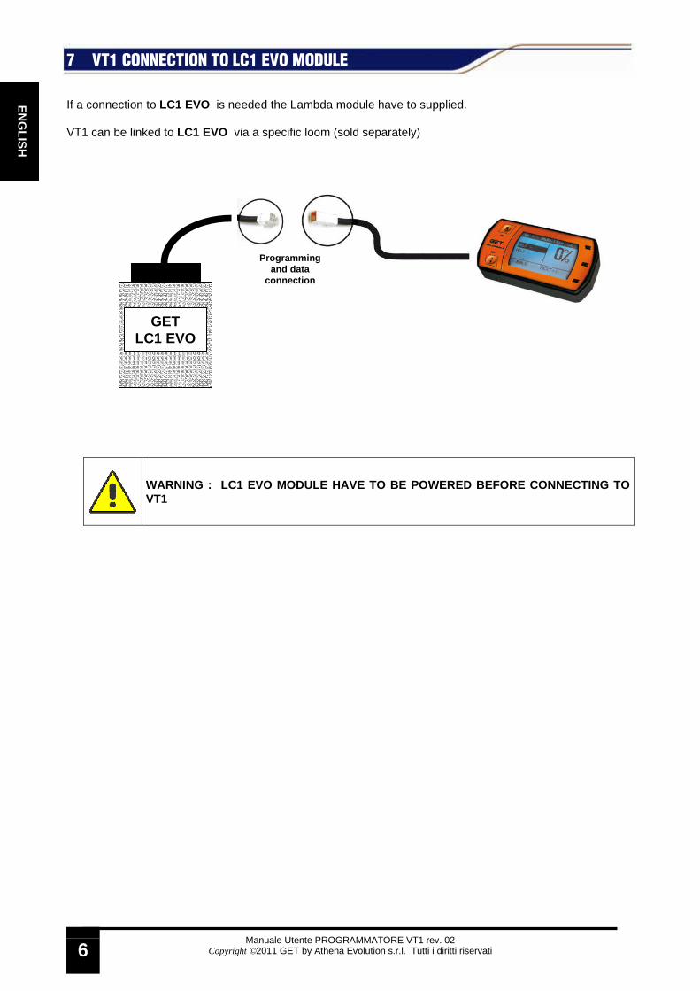
7 VT1 CONNECTION TO LC1 EVO MODULE If a connection to LC1 EVO is needed the Lambda module have to supplied. VT1 can be linked to LC1 EVO via a specific loom (sold separately)
WARNING : LC1 EVO MODULE HAVE TO BE POWERED BEFORE CONNECTING TO VT1
GET LC1 EVO
Programming and data
connection

Manuale Utente PROGRAMMATORE VT1 rev. 02
Copyright ©2011 GET by Athena Evolution s.r.l. Tutti i diritti riservati
7
EN
GLI
SH
8 VT1 CONTROLLS AND SIGNALS
8.1 VT1 BUTTON USE VT1 buttons have following functions: • S (SET) button: permit to enter menu/submenu and confirm operations • ARROW button: permit to move inside functions and change operations
8.2 SWITCH ON VT1 self switch on once is connected do a power supply (internal or external). The switch on sequence will switch on three LEDs, the visualization of initial page (initial splash) and at the end the MAIN page visualization. In the MAIN page it is possible to use the product.
Scroll button ARROW
Selection button S LAMBDA TARGET
UP LED
LAMBDA TARGET OK LED
LAMBDA TARGET DOWN LED
DISPLAY
INTERCONNECTION PLUG
EXTERNAL POWER SUPPLY (POSITIVE)
EXTERNAL POWER SUPPLY (NEGATIVE)
Manuale Utente PROGRAMMATORE VT1 rev. 02
Copyright ©2011 GET by Athena Evolution s.r.l. Tutti i diritti riservati
8
EN
GLIS
H
9 VT1 PAGES, MENU AND FUNCTION
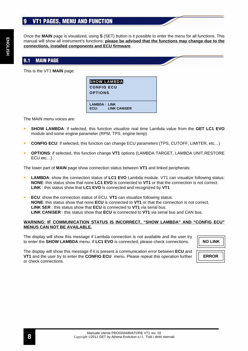
Once the MAIN page is visualized, using S (SET) button is it possible to enter the menu for all functions. This manual will show all instrument’s functions: please be advised that the functions may change due to the connections, installed components and ECU firmware . 9.1 MAIN PAGE This is the VT1 MAIN page: The MAIN menu voices are: • SHOW LAMBDA : if selected, this function visualize real time Lambda value from the GET LC1 EVO
module and some engine parameter (RPM, TPS, engine temp)
• CONFIG ECU: if selected, this function can change ECU parameters (TPS, CUTOFF, LIMITER, etc…) • OPTIONS: if selected, this function change VT1 options (LAMBDA TARGET, LAMBDA UNIT,RESTORE
ECU etc…) The lower part of MAIN page show connection status between VT1 and linked peripherals: • LAMBDA : show the connection status of LC1 EVO Lambda module. VT1 can visualize following status:
NONE: this status show that none LC1 EVO is connected to VT1 or that the connection is not correct. LINK : this status show that LC1 EVO is connected and recognized by VT1
• ECU: show the connection status of ECU. VT1 can visualize following status: NONE: this status show that none ECU is connected to VT1 or that the connection is not correct. LINK SER : this status show that ECU is connected to VT1 via serial bus. LINK CAN\SER : this status show that ECU is connected to VT1 via serial bus and CAN bus.
WARNING: IF COMMUNICATION STATUS IS INCORRECT, “SHO W LAMBDA” AND “CONFIG ECU” MENUS CAN NOT BE AVAILABLE. The display will show this message if Lambda connection is not available and the user try to enter the SHOW LAMBDA menu. If LC1 EVO is connected, please check connections. The display will show this message if it is present a communication error between ECU and VT1 and the user try to enter the CONFIG ECU menu. Please repeat this operation further or check connections.
SHOW LAMBDA
CONFIG ECU OPTIONS
LAMBDA : LINK ECU: LINK CAN\SER
NO LINK
ERROR

Manuale Utente PROGRAMMATORE VT1 rev. 02
Copyright ©2011 GET by Athena Evolution s.r.l. Tutti i diritti riservati
9
EN
GLI
SH
9.2 SHOW LAMBDA MENU SHOW LAMBDA menu visualize LC1 EVO module if connected to the system. Use ARROW button to move the cursor to the SHOW LAMBDA voice, press S (SET) button:
Inside the page you will see: • 1 – number of the sensor monitored by VT1 and Lambda value
measurement unit (STO or AFR) • 2 – Lambda value • 3 – RPM : engine speed (revolution per minute) • 4 – TPS : throttle percentage • 5 – TLMB : exaust gas temperature • 6 – TENG : engine temperature Pushing again S (SET) button you will visualize the resuming page of all linked Lambda sensors (this is useful if multiple sensor are installed). In this page all values are shown real time. TLMB value is not visualized. NOTE: VT1 can show 4 Lambda sensors (connected to L C1 EVO). The example in this manual is referred to a single sensor setup. To get back to MAIN page, from resume page, you have to press S (SET) button. You can get back directly to MAIN page, from all pages, using ARROW button.
SHOW LAMBDA CONFIG ECU
OPTIONS
LAMBDA : LINK ECU: LINK CAN \SER
0.92
LAMBDA 1 (STO)
RPM 5000 TPS 56
TLMB 980°C TENG 85°C
LAMBDA 1 (STO): 0.92
RPM 5000 TPS 56
TENG 85°C
0.92 2
LAMBDA 1 (STO) 1
RPM 5000 3 TPS 56 4
TLMB 980°C 5 TENG 85°C 6
Manuale Utente PROGRAMMATORE VT1 rev. 02
Copyright ©2011 GET by Athena Evolution s.r.l. Tutti i diritti riservati
10
EN
GLIS
H
9.3 CONFIG ECU MENU
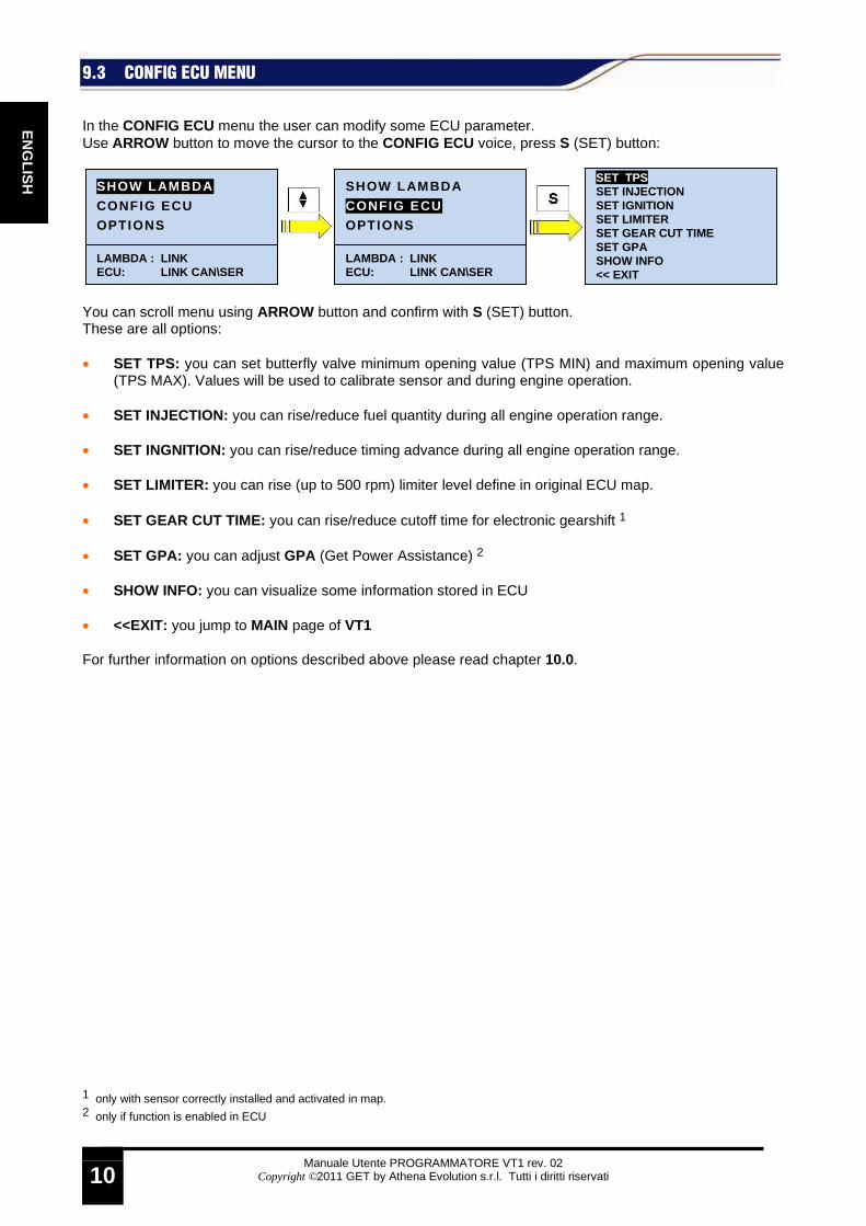
In the CONFIG ECU menu the user can modify some ECU parameter. Use ARROW button to move the cursor to the CONFIG ECU voice, press S (SET) button: You can scroll menu using ARROW button and confirm with S (SET) button. These are all options: • SET TPS: you can set butterfly valve minimum opening value (TPS MIN) and maximum opening value
(TPS MAX). Values will be used to calibrate sensor and during engine operation. • SET INJECTION: you can rise/reduce fuel quantity during all engine operation range.
• SET INGNITION: you can rise/reduce timing advance during all engine operation range. • SET LIMITER: you can rise (up to 500 rpm) limiter level define in original ECU map. • SET GEAR CUT TIME: you can rise/reduce cutoff time for electronic gearshift 1 • SET GPA: you can adjust GPA (Get Power Assistance) 2
• SHOW INFO: you can visualize some information stored in ECU
• <<EXIT: you jump to MAIN page of VT1 For further information on options described above please read chapter 10.0.
1 only with sensor correctly installed and activated in map. 2 only if function is enabled in ECU
SHOW LAMBDA
CONFIG ECU OPTIONS
LAMBDA : LINK ECU: LINK CAN \SER
SET TPS SET INJECTION SET IGNITION SET LIMITER SET GEAR CUT TIME SET GPA SHOW INFO << EXIT
SHOW LAMBDA
CONFIG ECU OPTIONS
LAMBDA : LINK ECU: LINK CAN \SER
Manuale Utente PROGRAMMATORE VT1 rev. 02
Copyright ©2011 GET by Athena Evolution s.r.l. Tutti i diritti riservati
11
EN
GLI
SH
9.4 OPTIONS MENU
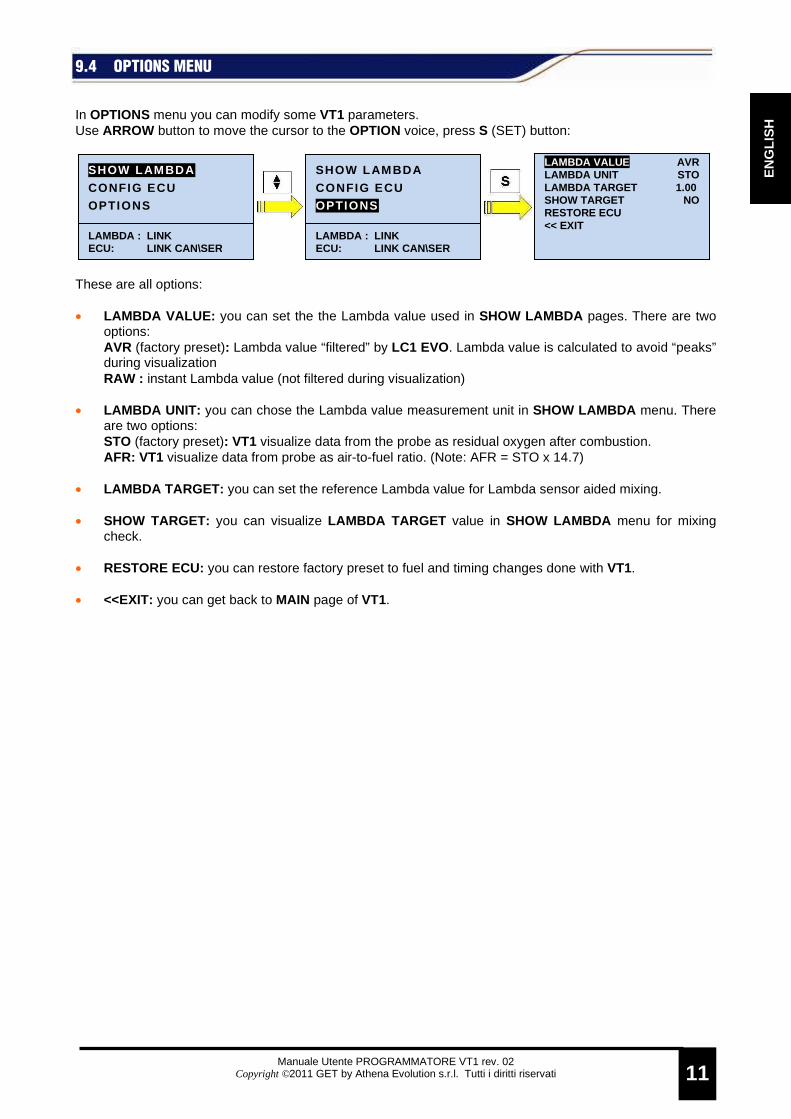
In OPTIONS menu you can modify some VT1 parameters. Use ARROW button to move the cursor to the OPTION voice, press S (SET) button: These are all options: • LAMBDA VALUE: you can set the the Lambda value used in SHOW LAMBDA pages. There are two
options: AVR (factory preset): Lambda value “filtered” by LC1 EVO. Lambda value is calculated to avoid “peaks” during visualization RAW : instant Lambda value (not filtered during visualization)
• LAMBDA UNIT: you can chose the Lambda value measurement unit in SHOW LAMBDA menu. There
are two options: STO (factory preset): VT1 visualize data from the probe as residual oxygen after combustion. AFR: VT1 visualize data from probe as air-to-fuel ratio. (Note: AFR = STO x 14.7)
• LAMBDA TARGET: you can set the reference Lambda value for Lambda sensor aided mixing.
• SHOW TARGET: you can visualize LAMBDA TARGET value in SHOW LAMBDA menu for mixing
check. • RESTORE ECU: you can restore factory preset to fuel and timing changes done with VT1. • <<EXIT: you can get back to MAIN page of VT1.
SHOW LAMBDA
CONFIG ECU OPTIONS
LAMBDA : LINK ECU: LINK CAN \SER
LAMBDA VALUE AVR LAMBDA UNIT STO LAMBDA TARGET 1.00 SHOW TARGET NO RESTORE ECU << EXIT
SHOW LAMBDA
CONFIG ECU OPTIONS
LAMBDA : LINK ECU: LINK CAN \SER

Manuale Utente PROGRAMMATORE VT1 rev. 02
Copyright ©2011 GET by Athena Evolution s.r.l. Tutti i diritti riservati
12
EN
GLIS
H
10 HOW TO …. Following chapters will explain you ho to use VT1. Unless otherwise indicated VT1 should be switch on and properly connected to EC1 and LC1 EVO. The reference page is MAIN page (visualized after the system is switched on).
10.1 TPS CALIBRATION To set correctly TPS (Throttle Position Sensor) it is necessary to select SET TPS function inside CONFIG ECU menu. The calibration has to be done with completely closed butterfly (TPS MIN) and with completely open butterfly (TPS MAX). Modification have effect only once stored in ECU. Please proceed as follow: • Enter the calibration page for completely closed butterfly (TPS MIN): the display show MIN in the top left
part • Close completely the throttle (and maintain the position) • Press S (SET) button once CAPTURE is visualized: VT1 will show the digital value red by the sensor
increased by one unit. • NEXT >> is visualized: push S (SET) button • VT1 enter the wide open throttle calibration (TPS MAX): the display show MAX in the top left part • Open completely the throttle (and maintain the position) • Press S (SET) button once CAPTURE is visualized: VT1 will show the digital value red by the sensor
decreased by one unit. • NEXT >> is visualized: push S (SET) button • Release the throttle • VT1 resume the completed calibration: move selection from <<BACK to NEXT>> with ARROW button
and press S (SET) • VT1 visualize all set values: if you want to store calibration push S (SET) button once YES voice is
selected.
MAX - TPS CUR: 198 CAPTURE ADJ + ADJ - 197 << BACK NEXT >>
MIN - TPS CUR: 58 CAPTURE ADJ + ADJ - 058 << BACK NEXT >>
MIN - TPS CUR: 58 CAPTURE ADJ + ADJ - 059 << BACK NEXT >>
SET TPS SET INJECTION SET IGNITION SET LIMITER SET GEAR CUT TIME SET GPA SHOW INFO << EXIT
SHOW LAMBDA CONFIG ECU
OPTIONS
LAMBDA : LINK ECU: LINK CAN \SER
MAX - TPS CUR: 198 CAPTURE ADJ + ADJ - 197 << BACK NEXT >>
TPS CURRENT: 198
TPS MIN: 59 TPS MAX: 197
<< BACK NEXT >>
TPS CURRENT: 198
TPS MIN: 59 TPS MAX: 197
<< BACK NEXT >>
WARNING
SAVE? YES NO
Manuale Utente PROGRAMMATORE VT1 rev. 02
Copyright ©2011 GET by Athena Evolution s.r.l. Tutti i diritti riservati
13
EN
GLI
SH
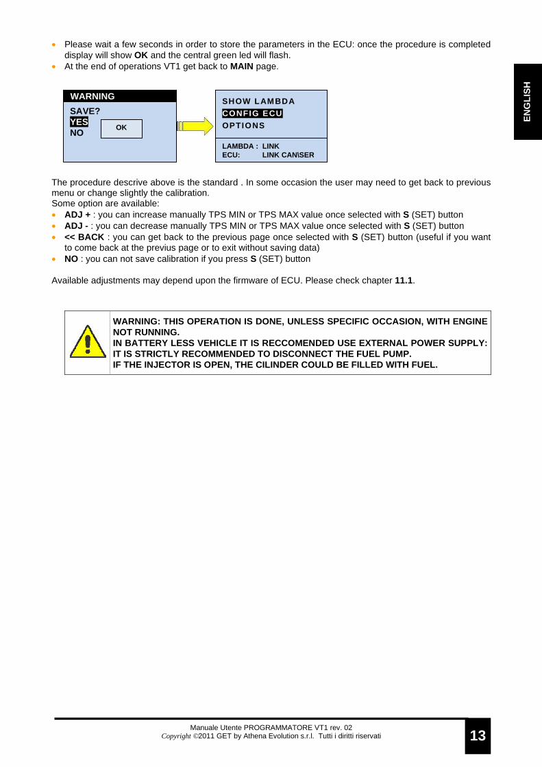
• Please wait a few seconds in order to store the parameters in the ECU: once the procedure is completed display will show OK and the central green led will flash.
• At the end of operations VT1 get back to MAIN page. The procedure descrive above is the standard . In some occasion the user may need to get back to previous menu or change slightly the calibration. Some option are available: • ADJ + : you can increase manually TPS MIN or TPS MAX value once selected with S (SET) button • ADJ - : you can decrease manually TPS MIN or TPS MAX value once selected with S (SET) button • << BACK : you can get back to the previous page once selected with S (SET) button (useful if you want
to come back at the previus page or to exit without saving data) • NO : you can not save calibration if you press S (SET) button Available adjustments may depend upon the firmware of ECU. Please check chapter 11.1.
WARNING: THIS OPERATION IS DONE, UNLESS SPECIFIC OC CASION, WITH ENGINE NOT RUNNING. IN BATTERY LESS VEHICLE IT IS RECCOMENDED USE EXTER NAL POWER SUPPLY: IT IS STRICTLY RECOMMENDED TO DISCONNECT THE FUEL PUMP. IF THE INJECTOR IS OPEN, THE CILINDER COULD BE FILL ED WITH FUEL.
SHOW LAMBDA CONFIG ECU OPTIONS
LAMBDA : LINK ECU: LINK CAN \SER
SAVE? YES NO
WARNING
OK

Manuale Utente PROGRAMMATORE VT1 rev. 02
Copyright ©2011 GET by Athena Evolution s.r.l. Tutti i diritti riservati
14
EN
GLIS
H
10.2 INJECTED FUEL QUANTITY ADJUSTMENT The fuel quantity injected in all engine range could be modified using SET INJECTION function inside CONFIG ECU menu. With this function the user can add or remove fuel (INJ_OFFSET) changing injection open time. This correction can be done also with engine running. SET INJECTION sets independently two maps in ECU (MAP1 and MAP2). Modification have effect only once stored in ECU. Please proceed as follow: • Enter SET INJECTION page. • Select the map you want to modify (example MAP1) pushing S (SET) button. • Push S (SET) when ADJ+ is visualized to increase fuel quantity: each time S (SET) is pushed percentage
is increased by 1%. To decrease fuel quantity move to ADJ- pushing ARROW and push S (SET). • Once completed all modifications, push ARROW to select NEXT >>. • Push S (SET): VT1 display the screen with all corrections. If you wish to save the configuration push S
(SET) once YES is selected. • Please wait a few seconds in order to store the parameters in the ECU: once the procedure is completed
display will show OK and the central green led will flash. • At the end of operations VT1 get back to MAIN page.
This is the meaning of some other functions: • << BACK : you can get back to the previous page once selected with S (SET) button (useful if you want
to come back at the previus page or to exit without saving data) • NO : you can avoid to save the configuration once selected with S (SET) button WARNING: INJECTION OFFSET PREVIOUSLY SET WILL BE RE D BY VT1 Available adjustments may depend upon the firmware of ECU. Please check chapter 11.1.
SAVE? YES NO
WARNING
SAVE? YES NO
WARNING
OK
MAP1 - INJECTION : 00%
ADJ + ADJ - +01% << BACK NEXT >>
MAP1 - INJECTION : 00%
ADJ + ADJ - +01% << BACK NEXT >>
SET TPS SET INJECTION SET IGNITION SET LIMITER SET GEAR CUT TIME SET GPA SHOW INFO << EXIT
SHOW LAMBDA CONFIG ECU OPTIONS
LAMBDA : LINK ECU: LINK CAN\SER
MAP1 - INJECTION : 00%
ADJ + ADJ - 00% << BACK NEXT >>
SET TPS SET INJECTION SET IGNITION SET LIMITER SET GEAR CUT TIME SET GPA SHOW INFO << EXIT
SET INJECTION
MAP1 MAP2 <<EXIT
Manuale Utente PROGRAMMATORE VT1 rev. 02
Copyright ©2011 GET by Athena Evolution s.r.l. Tutti i diritti riservati
15
EN
GLI
SH
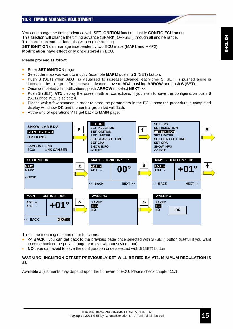
10.3 TIMING ADVANCE ADJUSTMENT You can change the timing advance with SET IGNITION function, inside CONFIG ECU menu. This function will change the timing advance (SPARK_OFFSET) through all engine range. This correction can be done also with engine running. SET IGNITION can manage independently two ECU maps (MAP1 and MAP2). Modification have effect only once stored in ECU. Please proceed as follow: • Enter SET IGNITION page • Select the map you want to modify (example MAP1) pushing S (SET) button. • Push S (SET) when ADJ+ is visualized to increase advance: each time S (SET) is pushed angle is
increased by 1 degree. To decrease advance move to ADJ- pushing ARROW and push S (SET). • Once completed all modifications, push ARROW to select NEXT >>. • Push S (SET): VT1 display the screen with all corrections. If you wish to save the configuration push S
(SET) once YES is selected. • Please wait a few seconds in order to store the parameters in the ECU: once the procedure is completed
display will show OK and the central green led will flash. • At the end of operations VT1 get back to MAIN page. This is the meaning of some other functions: • << BACK : you can get back to the previous page once selected with S (SET) button (useful if you want
to come back at the previus page or to exit without saving data) • NO : you can avoid to save the configuration once selected with S (SET) button WARNING: INGNITION OFFSET PREVIOUSLY SET WILL BE RE D BY VT1. MINIMUM REGULATION IS ±1°. Available adjustments may depend upon the firmware of ECU. Please check chapter 11.1.
SAVE? YES NO
WARNING
SAVE? YES NO
WARNING
OK
MAP1 - IGNITION : 00°
ADJ + ADJ - +01° << BACK NEXT >>
SET TPS SET INJECTION SET IGNITION SET LIMITER SET GEAR CUT TIME SET GPA SHOW INFO << EXIT
SHOW LAMBDA CONFIG ECU
OPTIONS
LAMBDA : LINK ECU: LINK CAN \SER
SET TPS SET INJECTION SET IGNITION SET LIMITER SET GEAR CUT TIME SET GPA SHOW INFO << EXIT
MAP1 - IGNITION : 00°
ADJ + ADJ - +01° << BACK NEXT >>
MAP1 - IGNITION : 00°
ADJ + ADJ - 00° << BACK NEXT >>
SET IGNITION
MAP1 MAP2 <<EXIT
Manuale Utente PROGRAMMATORE VT1 rev. 02
Copyright ©2011 GET by Athena Evolution s.r.l. Tutti i diritti riservati
16
EN
GLIS
H
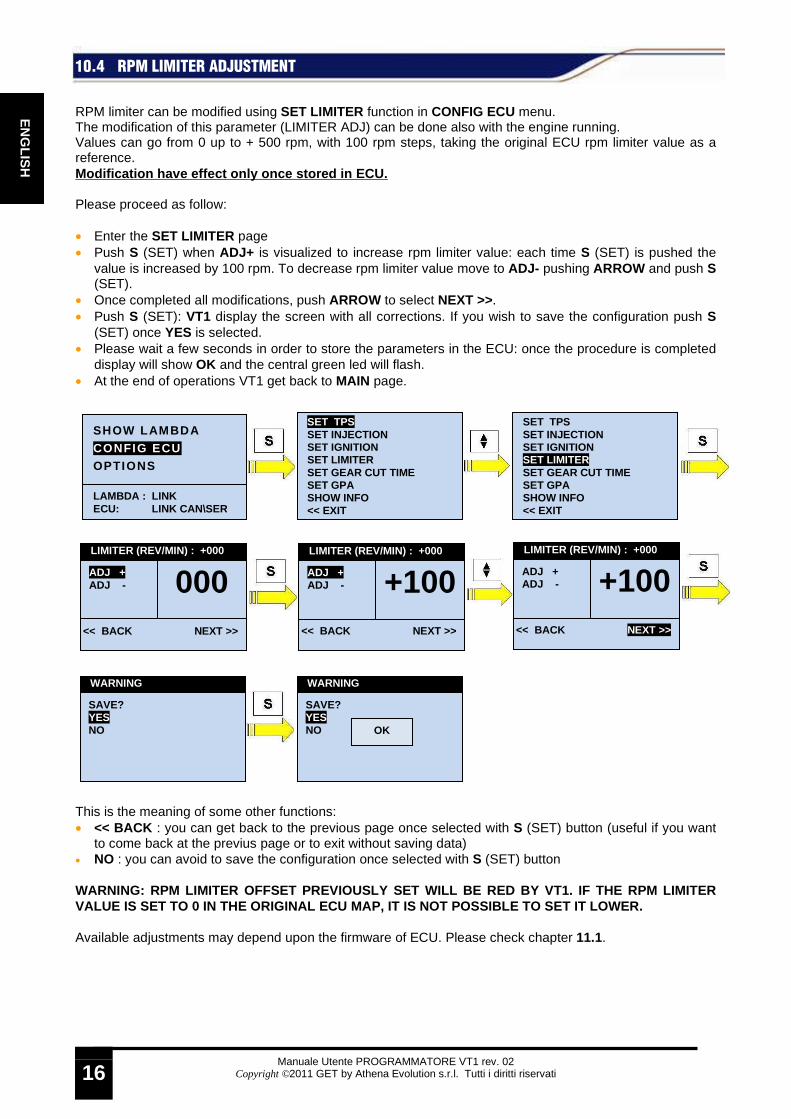
10.4 RPM LIMITER ADJUSTMENT RPM limiter can be modified using SET LIMITER function in CONFIG ECU menu. The modification of this parameter (LIMITER ADJ) can be done also with the engine running. Values can go from 0 up to + 500 rpm, with 100 rpm steps, taking the original ECU rpm limiter value as a reference. Modification have effect only once stored in ECU. Please proceed as follow: • Enter the SET LIMITER page • Push S (SET) when ADJ+ is visualized to increase rpm limiter value: each time S (SET) is pushed the
value is increased by 100 rpm. To decrease rpm limiter value move to ADJ- pushing ARROW and push S (SET).
• Once completed all modifications, push ARROW to select NEXT >>. • Push S (SET): VT1 display the screen with all corrections. If you wish to save the configuration push S
(SET) once YES is selected. • Please wait a few seconds in order to store the parameters in the ECU: once the procedure is completed
display will show OK and the central green led will flash. • At the end of operations VT1 get back to MAIN page. This is the meaning of some other functions: • << BACK : you can get back to the previous page once selected with S (SET) button (useful if you want
to come back at the previus page or to exit without saving data) • NO : you can avoid to save the configuration once selected with S (SET) button WARNING: RPM LIMITER OFFSET PREVIOUSLY SET WILL BE RED BY VT1. IF THE RPM LIMITER VALUE IS SET TO 0 IN THE ORIGINAL ECU MAP, IT IS NO T POSSIBLE TO SET IT LOWER. Available adjustments may depend upon the firmware of ECU. Please check chapter 11.1.
SAVE? YES NO
WARNING
SAVE? YES NO
WARNING
OK
LIMITER (REV/MIN) : +000
ADJ + ADJ - +100 << BACK NEXT >>
SET TPS SET INJECTION SET IGNITION SET LIMITER SET GEAR CUT TIME SET GPA SHOW INFO << EXIT
SHOW LAMBDA CONFIG ECU OPTIONS
LAMBDA : LINK ECU: LINK CAN \SER
LIMITER (REV/MIN) : +000
ADJ + ADJ - +100 << BACK NEXT >>
SET TPS SET INJECTION SET IGNITION SET LIMITER SET GEAR CUT TIME SET GPA SHOW INFO << EXIT
LIMITER (REV/MIN) : +000
ADJ + ADJ - 000 << BACK NEXT >>

Manuale Utente PROGRAMMATORE VT1 rev. 02
Copyright ©2011 GET by Athena Evolution s.r.l. Tutti i diritti riservati
17
EN
GLI
SH
10.5 CUTOFF ADJUSTMENT It is possible to change the cutoff time for the electronic gearshift (GEAR CUT TIME) using SET GEAR CUT TIME function in CONFIG ECU menu. This correction can be done also with engine running. Values can be changed from 0 to 500 ms (milliseconds) with 2 ms steps. Modification have effect only once stored in ECU. Please proceed as follow: • Enter SET GEAR CUT TIME page • Push S (SET) when ADJ+ is visualized to increase cutoff time: each time S (SET) is pushed time is
increased by 2 ms. To decrease cutoff time move to ADJ- pushing ARROW and push S (SET). • Once completed all modifications, push ARROW to select NEXT >>. • Push S (SET): VT1 display the screen with all corrections. If you wish to save the configuration push S
(SET) once YES is selected. • Please wait a few seconds in order to store the parameters in the ECU: once the procedure is completed
display will show OK and the central green led will flash. • At the end of operations VT1 get back to MAIN page. This is the meaning of some other functions: • << BACK : you can get back to the previous page once selected with S (SET) button (useful if you want
to come back at the previus page or to exit without saving data) • NO : you can avoid to save the configuration once selected with S (SET) button WARNING: ELECTRONIC GEARSHIFT IS IMPLEMENTED ONLY I F THE SENSOR IS CONNECTED TO ECU AND THE MAP CONTAIN THE FUNCTION. Available adjustments may depend upon the firmware of ECU. Please check chapter 11.1.
SAVE? YES NO
WARNING
SAVE? YES NO
WARNING
OK
SHIFT TIME (MS) : +000
ADJ + ADJ - 002 << BACK NEXT >>
SET TPS SET INJECTION SET IGNITION SET LIMITER SET GEAR CUT TIME SET GPA SHOW INFO << EXIT
SHOW LAMBDA CONFIG ECU OPTIONS
LAMBDA : LINK ECU: LINK CAN\SER
SHIFT TIME (MS) : +000
ADJ + ADJ - 002 << BACK NEXT >>
SET TPS SET INJECTION SET IGNITION SET LIMITER SET GEAR CUT TIME SET GPA SHOW INFO << EXIT
SHIFT TIME (MS) : +000
ADJ + ADJ - 000 << BACK NEXT >>

Manuale Utente PROGRAMMATORE VT1 rev. 02
Copyright ©2011 GET by Athena Evolution s.r.l. Tutti i diritti riservati
18
EN
GLIS
H
10.6 GPA (Get Power Assistance) ADJUSTMENT Using SET GPA inside CONFIG ECU menu it is possible to modify GPA (Get Power Assistance) settings. This correction can be done also with engine running. Values can be changed from 0 (system is off) to 10 (top of the range). SET GPA can manage two different maps (MAP1 and MAP2). Modification have effect only once stored in ECU. Please proceed as follow: • Enter SET GPA page • Select the map you want to modify (example MAP1) pushing S (SET) button. • Push S (SET) when ADJ+ is visualized to increase intervention: each time S (SET) is pushed intervention
is increased by 1 unit. To decrease intervention move to ADJ- pushing ARROW and push S (SET). • Once completed all modifications, push ARROW to select NEXT >>. • Push S (SET): VT1 display the screen with all corrections. If you wish to save the configuration push S
(SET) once YES is selected. • Please wait a few seconds in order to store the parameters in the ECU: once the procedure is completed
display will show OK and the central green led will flash. • At the end of operations VT1 get back to MAIN page. This is the meaning of some other functions: • << BACK : you can get back to the previous page once selected with S (SET) button (useful if you want
to come back at the previus page or to exit without saving data) • NO : you can avoid to save the configuration once selected with S (SET) button WARNING: GPA FUNCTION IS ACTIVATED ONLY IF IT IS IM PLEMENTED IN ECU. Available adjustments may depend upon the firmware of ECU. Please check chapter 11.1.
MAP1 - GPA : 00
ADJ + ADJ - 01 << BACK NEXT >>
SET TPS SET INJECTION SET IGNITION SET LIMITER SET GEAR CUT TIME SET GPA SHOW INFO << EXIT
SHOW LAMBDA
CONFIG ECU OPTIONS
LAMBDA : LINK ECU: LINK CAN \SER
MAP1 - GPA : 00
ADJ + ADJ - 00 << BACK NEXT >>
SET TPS SET INJECTION SET IGNITION SET LIMITER SET GEAR CUT TIME SET GPA SHOW INFO << EXIT
SET IGNITION
MAP1 MAP2 <<EXIT
SAVE? YES NO
WARNING
SAVE? YES NO
WARNING
OK
MAP1 - GPA : 00
ADJ + ADJ - 01 << BACK NEXT >>

Manuale Utente PROGRAMMATORE VT1 rev. 02
Copyright ©2011 GET by Athena Evolution s.r.l. Tutti i diritti riservati
19
EN
GLI
SH
10.7 LAMBDA SENSOR AIDED MIXING CHECK VT1 can adjust ideal mixing (LAMBDA TARGET ). This parameter setting will check the fixed value and a real time value (using LC1 Lambda sensor). Please proceed as follow: • Select OPTIONS in MAIN page pushing S (SET) button. • Push ARROW to move to LAMBDA TARGET and confirm with S (SET) button • Select desired value: modify values with ARROW and confirm with S (SET) button • Push ARROW to move to SHOW TARGET and push S (SET): the selection will move to the option value • Change the option from NO to YES pushing ARROW and confirm with S (SET) • Once completed all modifications, push ARROW to select <<EXIT and confirm with S (SET). VT1 will be
back to MAIN page.
WARNING: THE LAMBDA VALUE SHOWN IN THE PAGES ABOVE IS FOR DISPLAY POURPOSE ONLY.
• From MAIN page, select SHOW LAMBDA voice pushing S (SET) • In the upper part of the screen the previously set LAMBDA TARGET is displayed. In the central part is
displayed the real time value:
SHOW LAMBDA
CONFIG ECU
OPTIONS
LAMBDA : LINK ECU: LINK CAN \SER
LAMBDA VALUE AVR LAMBDA UNIT STO LAMBDA TARGET 0.00 SHOW TARGET NO RESTORE ECU << EXIT
SHOW LAMBDA
CONFIG ECU
OPTIONS
LAMBDA : LINK ECU: LINK CAN \SER
LAMBDA VALUE AVR LAMBDA UNIT STO LAMBDA TARGET 0.00 SHOW TARGET NO RESTORE ECU << EXIT
LAMBDA VALUE AVR LAMBDA UNIT STO LAMBDA TARGET 0.0 0 SHOW TARGET NO RESTORE ECU << EXIT
LAMBDA VALUE AVR LAMBDA UNIT STO LAMBDA TARGET 0.0 1 SHOW TARGET NO RESTORE ECU << EXIT
LAMBDA VALUE AVR LAMBDA UNIT STO LAMBDA TARGET 0. 01 SHOW TARGET NO RESTORE ECU << EXIT
LAMBDA VALUE AVR LAMBDA UNIT STO LAMBDA TARGET 0. 11 SHOW TARGET NO RESTORE ECU << EXIT
LAMBDA VALUE AVR LAMBDA UNIT STO LAMBDA TARGET 0.11 SHOW TARGET NO RESTORE ECU << EXIT
LAMBDA VALUE AVR LAMBDA UNIT STO LAMBDA TARGET 1.11 SHOW TARGET NO RESTORE ECU << EXIT
LAMBDA VALUE AVR LAMBDA UNIT STO LAMBDA TARGET 1.11 SHOW TARGET NO RESTORE ECU << EXIT
LAMBDA VALUE AVR LAMBDA UNIT STO LAMBDA TARGET 1.11 SHOW TARGET NO RESTORE ECU << EXIT
LAMBDA VALUE AVR LAMBDA UNIT STO LAMBDA TARGET 1.11 SHOW TARGET NO RESTORE ECU << EXIT
LAMBDA VALUE AVR LAMBDA UNIT STO LAMBDA TARGET 1.11 SHOW TARGET YES RESTORE ECU << EXIT
LAMBDA VALUE AVR LAMBDA UNIT STO LAMBDA TARGET 1.11 SHOW TARGET YES RESTORE ECU << EXIT
Manuale Utente PROGRAMMATORE VT1 rev. 02
Copyright ©2011 GET by Athena Evolution s.r.l. Tutti i diritti riservati
20
EN
GLIS
H
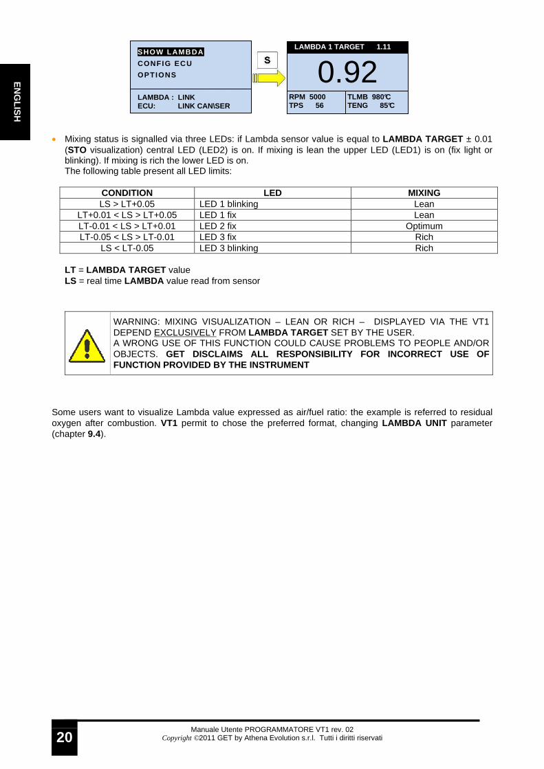
• Mixing status is signalled via three LEDs: if Lambda sensor value is equal to LAMBDA TARGET ± 0.01 (STO visualization) central LED (LED2) is on. If mixing is lean the upper LED (LED1) is on (fix light or blinking). If mixing is rich the lower LED is on. The following table present all LED limits:
CONDITION LED MIXING LS > LT+0.05 LED 1 blinking Lean
LT+0.01 < LS > LT+0.05 LED 1 fix Lean LT-0.01 < LS > LT+0.01 LED 2 fix Optimum LT-0.05 < LS > LT-0.01 LED 3 fix Rich
LS < LT-0.05 LED 3 blinking Rich LT = LAMBDA TARGET value LS = real time LAMBDA value read from sensor
Some users want to visualize Lambda value expressed as air/fuel ratio: the example is referred to residual oxygen after combustion. VT1 permit to chose the preferred format, changing LAMBDA UNIT parameter (chapter 9.4).
WARNING: MIXING VISUALIZATION – LEAN OR RICH – DISPLAYED VIA THE VT1 DEPEND EXCLUSIVELY FROM LAMBDA TARGET SET BY THE USER. A WRONG USE OF THIS FUNCTION COULD CAUSE PROBLEMS TO PEOPLE AND/OR OBJECTS. GET DISCLAIMS ALL RESPONSIBILITY FOR INCORRECT USE OF FUNCTION PROVIDED BY THE INSTRUMENT
SHOW LAMBDA
CONFIG ECU
OPTIONS
LAMBDA : LINK ECU: LINK CAN \SER
0.92
LAMBDA 1 TARGET 1.11
RPM 5000 TPS 56
TLMB 980°C TENG 85°C

Manuale Utente PROGRAMMATORE VT1 rev. 02
Copyright ©2011 GET by Athena Evolution s.r.l. Tutti i diritti riservati
21
EN
GLI
SH
10.8 ORIGINAL ECU VALUES RESTORE VT1 can restore all original ECU setting (erasing all VT1 modifications) or modification to timing and injection. To restore timing and injection parameters please proceed as follow: • Select OPTIONS in MAIN page pushing S (SET) • Push ARROW moving to RESTORE ECU option: confirm with S (SET) • Select ERASE CORRECTIONS (with ARROW) and push S (SET) • VT1 asks for confirmation. If you need to erase modification to timing and injection press S (SET) once
YES is selected. • At the end of operations VT1 get back to MAIN page. This is the meaning of some other functions: • << EXIT : you can get back to the MAIN page with no modifications. • NO : you can avoid to save the configuration once selected with S (SET) button
SHOW LAMBDA
CONFIG ECU
OPTIONS
LAMBDA : LINK ECU: LINK CAN \SER
LAMBDA VALUE AVR LAMBDA UNIT STO LAMBDA TARGET 0.00 SHOW TARGET NO RESTORE ECU << EXIT
SHOW LAMBDA
CONFIG ECU
OPTIONS
LAMBDA : LINK ECU: LINK CAN \SER
LAMBDA VALUE AVR LAMBDA UNIT STO LAMBDA TARGET 0.00 SHOW TARGET NO RESTORE ECU << EXIT
ERASE CORRECTIONS RESTORE FACTORY VAL. << EXIT
ERASE CORRECTIONS? YES NO
WARNING
ERASE CORRECTIONS? YES NO
WARNING
OK
Manuale Utente PROGRAMMATORE VT1 rev. 02
Copyright ©2011 GET by Athena Evolution s.r.l. Tutti i diritti riservati
22
EN
GLIS
H
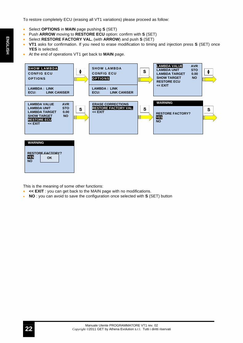
To restore completely ECU (erasing all VT1 variations) please proceed as follow: • Select OPTIONS in MAIN page pushing S (SET) • Push ARROW moving to RESTORE ECU option: confirm with S (SET) • Select RESTORE FACTORY VAL. (with ARROW) and push S (SET) • VT1 asks for confirmation. If you need to erase modification to timing and injection press S (SET) once
YES is selected. • At the end of operations VT1 get back to MAIN page. This is the meaning of some other functions: • << EXIT : you can get back to the MAIN page with no modifications. • NO : you can avoid to save the configuration once selected with S (SET) button
SHOW LAMBDA
CONFIG ECU
OPTIONS
LAMBDA : LINK ECU: LINK CAN \SER
LAMBDA VALUE AVR LAMBDA UNIT STO LAMBDA TARGET 0.00 SHOW TARGET NO RESTORE ECU << EXIT
SHOW LAMBDA
CONFIG ECU
OPTIONS
LAMBDA : LINK ECU: LINK CAN \SER
LAMBDA VALUE AVR LAMBDA UNIT STO LAMBDA TARGET 0.00 SHOW TARGET NO RESTORE ECU << EXIT
ERASE CORRECTIONS RESTORE FACTORY VAL. << EXIT
RESTORE FACTORY? YES NO
WARNING
RESTORE FACTORY? YES NO
WARNING
OK
Manuale Utente PROGRAMMATORE VT1 rev. 02
Copyright ©2011 GET by Athena Evolution s.r.l. Tutti i diritti riservati
23
EN
GLI
SH
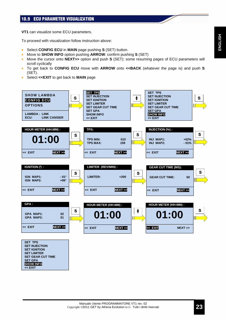
10.9 ECU PARAMETER VISUALIZATION VT1 can visualize some ECU parameters. To proceed with visualization follow instruction above: • Select CONFIG ECU in MAIN page pushing S (SET) button. • Move to SHOW INFO option pushing ARROW: confirm pushing S (SET) • Move the cursor onto NEXT>> option and push S (SET): some resuming pages of ECU parameters will
scroll cyclically • To get back to CONFIG ECU move with ARROW onto <<BACK (whatever the page is) and push S
(SET). • Select <<EXIT to get back to MAIN page
HOUR METER (HH:MM) :
01:00 << EXIT NEXT >>
INJECTION (%) :
INJ MAP1: +02% INJ MAP2: - 01%
<< EXIT NEXT >>
SET TPS SET INJECTION SET IGNITION SET LIMITER SET GEAR CUT TIME SET GPA SHOW INFO << EXIT
SHOW LAMBDA
CONFIG ECU OPTIONS
LAMBDA : LINK ECU: LINK CAN \SER
SET TPS SET INJECTION SET IGNITION SET LIMITER SET GEAR CUT TIME SET GPA SHOW INFO << EXIT
TPS:
TPS MIN: 010 TPS MAX: 159
<< EXIT NEXT >>
IGNITION (°) :
IGN MAP1: - 01° IGN MAP2: +06°
<< EXIT NEXT >>
LIMITER (REV/MIN) :
LIMITER: +200
<< EXIT NEXT >>
GEAR CUT TIME (MS):
GEAR CUT TIME: 50
<< EXIT NEXT >>
GPA :
GPA MAP1: 02 GPA MAP2: 01
<< EXIT NEXT >>
HOUR METER (HH:MM) :
01:00 << EXIT NEXT >>
HOUR METER (HH:MM) :
01:00 << EXIT NEXT >>
SET TPS SET INJECTION SET IGNITION SET LIMITER SET GEAR CUT TIME SET GPA SHOW INFO << EXIT

Manuale Utente PROGRAMMATORE VT1 rev. 02
Copyright ©2011 GET by Athena Evolution s.r.l. Tutti i diritti riservati
24
EN
GLIS
H
11 ECU COMPATIBILITY LIST The following table show compatibility between VT1 and ECU:
ECU COMPATIBILITY GP1 EVO Yes
11.1 ADJUSTMENT RANGE Available adjustments may depend upon the firmware of ECU. The following table show all functions:
FUNCTION ECU
GP1 EVO firmware 35 (or previous)
GP1 EVO firmware 36 (o later)
TPS calibration YES YES Mixing calibration YES from -10% to + 15% YES from -10% to + 30% Timing calibration YES from -5° to + 5° YES from -3 0° to + 5° Rpm limiter calibration YES from 0 rpm to + 500 rpm YES from 0 rpm to + 500 rpm GEAR CUT TIME calibration NO1 YES from 0 ms to 500 ms GPA calibration NO1 YES 2
1 only with sensor correctly installed and activated in map. 2 only if function is enabled in ECU

Manuale Utente PROGRAMMATORE VT1 rev. 02
Copyright ©2011 GET by Athena Evolution s.r.l. Tutti i diritti riservati
25
EN
GLI
SH
12 FIRMWARE UPDATE It is possible update the VT1 firmware via pc and a connection cable. This is the list of what you need to proceed: • computer • the updated firmware must be saved in the computer • power supply (12 VDC - 18VDC) for PL00130000 • PL00130000 serial cable (same as ECU GP1 EVO) • USB-serial connection (if PC doesn’t have a physical serial port) approved by GET To update please proceed as follow: • Isolate red and black wires for external power supply for VT1 • Connect cable PL00130000 to computer through serial port (or to USB-serial interface) • Enable the “program mode” plugging connector onto the PL00130000 cable • Connect the PL00130000 to an external power supply (12 VDC - 18VDC) • Connect VT1 to PL00130000 through white 8 pins connector and verify that it is correctly switched on • Left click on “fwupdate.exe” icon to start firmware update. • Select the serial communication port (COM Port ) where the VT1 is connected
NOTE: if the cable is connected to a physical seria l port, usually it is necessary to select COM1. if a USB-serial adaptor is used, it is necessary check the proper address through Windows.

Manuale Utente PROGRAMMATORE VT1 rev. 02
Copyright ©2011 GET by Athena Evolution s.r.l. Tutti i diritti riservati
26
EN
GLIS
H
• Press UPDATE button and confirm: wait until the end of the procedure WARNING: DO NOT DISCONNET TEH CABLE UNTIL THE VT1 IS REBOOTED
• At the end of procedure disconnect the cable
WARNING: IF THIS PROCEDURE IS NOT FOLLOWED EXACTLY AND/OR AN INCORRECT POWER SUPPLY MAY DAMAGE VT1: IN THIS CASE GET TECHNICAL DEPARTMENT MAY NEED TO OPERATE THE UNIT.
Manuale Utente PROGRAMMATORE VT1 rev. 02
Copyright ©2011 GET by Athena Evolution s.r.l. Tutti i diritti riservati
27
EN
GLI
SH
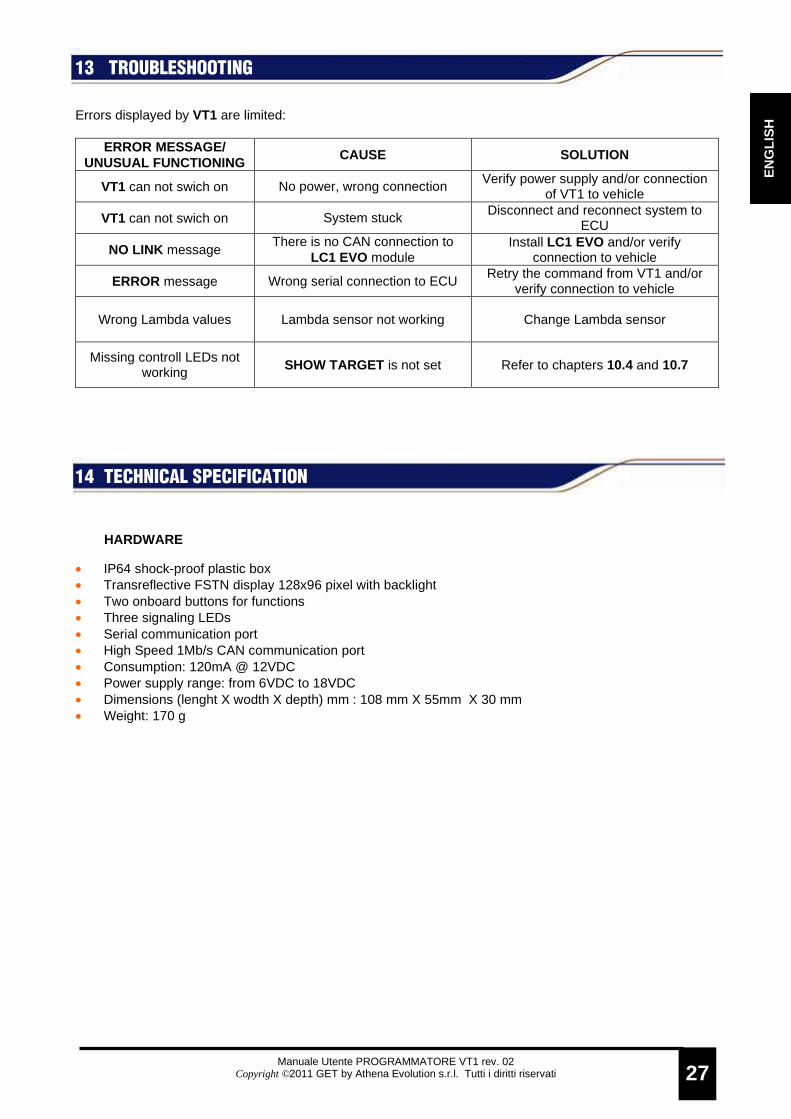
13 TROUBLESHOOTING Errors displayed by VT1 are limited:
ERROR MESSAGE/ UNUSUAL FUNCTIONING
CAUSE SOLUTION
VT1 can not swich on No power, wrong connection Verify power supply and/or connection
of VT1 to vehicle
VT1 can not swich on System stuck Disconnect and reconnect system to
ECU
NO LINK message There is no CAN connection to
LC1 EVO module Install LC1 EVO and/or verify
connection to vehicle
ERROR message Wrong serial connection to ECU Retry the command from VT1 and/or
verify connection to vehicle
Wrong Lambda values Lambda sensor not working Change Lambda sensor
Missing controll LEDs not working SHOW TARGET is not set Refer to chapters 10.4 and 10.7
14 TECHNICAL SPECIFICATION
HARDWARE
• IP64 shock-proof plastic box • Transreflective FSTN display 128x96 pixel with backlight • Two onboard buttons for functions • Three signaling LEDs • Serial communication port • High Speed 1Mb/s CAN communication port • Consumption: 120mA @ 12VDC • Power supply range: from 6VDC to 18VDC • Dimensions (lenght X wodth X depth) mm : 108 mm X 55mm X 30 mm • Weight: 170 g

Manuale Utente PROGRAMMATORE VT1 rev. 02
Copyright ©2011 GET by Athena Evolution s.r.l. Tutti i diritti riservati
28
EN
GLIS
H
NOTES:

Manuale Utente PROGRAMMATORE VT1 rev. 02
Copyright ©2011 GET by Athena Evolution s.r.l. Tutti i diritti riservati
29
EN
GLI
SH
ITALIANO
Direttive 2002/95/CE, 2002/96/CE e 2003/108/CE del Parlamento Europeo relative ai rifiuti di Apparecch iature Elettriche ed Elettroniche Smaltimento dei rifiuti elettrici ed elettronici (a pplicabile nell’Unione Europea e negli altri paesi europei con servizio di raccolta differenziata). II simbolo del cassonetto barrato presente sul prodotto o sulla sua confezione indica che il prodotto non deve essere trattato come rifiuto domestico, bensì raccolto separatamente ed essere consegnato ad un centro di raccolta autorizzato per il riciclo dei rifiuti elettrici ed elettronici (oppure reso al rivenditore nel momento dell’acquisto di un nuovo prodotto di tipo equivalente, in ragione di uno a uno). Provvedendo a che il prodotto venga smaltito in modo ambientalmente compatibile, si evita un potenziale impatto negativo sull’ambiente e per la salute umana, favorendo il reimpiego e/o riciclo dei materiali di cui è composta l’apparecchiatura. Lo smaltimento abusivo del prodotto da parte dell’utente comporta l’applicazione delle sanzioni amministrative previste dalla normativa vigente. Per adempiere correttamente alla normativa, i produttori partecipano a “sistemi collettivi” che hanno il compito di organizzare e gestire sistemi di raccolta dei RAEE provenienti dai nuclei domestici. Per maggiori informazioni, contattare l’ufficio preposto nella Vostra città, il servizio per lo smaltimento dei rifiuti domestici o il negozio in cui avete acquistato il prodotto. ENGLISH
Directive 2002/95/EC, 2002/96/EC and 2003/108/CE of the European Parliament on waste electrical and el ectronic equipment (WEEE) Disposal of old Electrical & Electronic Equipment ( applicable throughout the European Union and other European countries with separate collection programs). The symbol of crossed out wheeled bin, found on the product or on its packaging, indicates that this product should not be treated as household waste when you wish to dispose of it. Instead, it should be handed over to an applicable collection point (or the recycling of electrical and electronic equipment). By ensuring that product is disposed of correctly, you will help prevent potential negative consequences to the environment and human health, which could otherwise be caused by inappropriate disposal of this product. The recycling of materials will help to conserve natural resources. For more detailed information about the recycling of this product, please contact your local city office, household waste disposal service or the retail store where you purchased the product. FRANÇAIS
Directive 2002/95/CE, 2002/96/CE et 2003/108/CE du Parlement européen relative aux déchets d’équipemen ts électriques et électroniques (DEEE) Disposition concernant les anciens équipements élec triques et électroniques (applicable dans l’Union E uropéenne et dans d’autres pays européens avec des systèmes de collec te séparés). Ce symbole sur le produit ou sur son emballage indique que ce produit ne sera pas traité comme perte ménagère. Au lieu de cela il sera remis au point de collecte dédié pour le recyclage de l’équipement électrique et électronique. En s’assurant que ce produit est trié et jeté correctement, vous contribuerez a empêcher de potentielles conséquences négatives pour l’environnement et la santé humaine, qui pourraient autrement être provoquées par la manutention de rebut inadéquate de ce produit. La réutilisation des matériaux aidera à conserver les ressources naturelles. Pour des informations plus détaillé sur la réutilisation de ce produit, vous pouvez contacter votre mairie, la société de collecte et tri des rebuts ménagers ou le magasin où vous avez acheté le produit. DEUTSCH
Richtlinie 2002/95/EG, 2002/96/EG, 2003/108/EG des Europäischen Parlaments über Elektro- und Elektroni k-Altgeräte - Gemeinsame Erklärung Entsorgung von alten Elektro- und Elektronikgeraten (gültig in dar Europäischen Union und anderen euro päischen Ländern mit separatem Sammelsystem). Dieses Symbol auf dem Produkt oder auf der Verpackung bedeutet, dass dieses Produkt nicht wie Hausmüll behandelt werden darf. Stattdessen soll dieses Produkt zu dem geeigneten Entsorgungspunkt zum Recyceln von Elektro- und Elektronikgeraten gebracht werden. Wird das Produkt korrekt entsorgt, helfen Sie mit, negativen Umwelteinflussen und Gesundheitsschàden vorzubeugen, die durch unsachgemäße Entsorgung verursacht werden könnten. Das Recycling von Material wird unsere Naturressourcen erhalten. Für nähere Informationen über das Recyceln dieses Produktes kontaktieren Sie bitte Ihr lokales Bürgerbüro, Ihren Hausmüll Abholservice oder das Geschäft, in dem Sie dieses Produkt gekauft haben ESPAÑOL
Directiva 2002/95/CE, 2002/96/CE y 2003/108/CE del Parlamento Europeo sobre residuos de aparatos eléct ricos y electrónicos (RAEE) Legislación referida a la eliminación de residuos d e aparatos eléctricos y electrónicos (que se aplica en la Unión Europea y en los otros países europeos con servicio de recogida selectiva). El símbolo del contenedor de basura tachado presente en el producto o en el embalaje indica que el producto no se puede tratar como residuo doméstico, sino que se debe eliminar por separado y se debe entregar a un centro de recogida autorizado para el reciclaje de los residuos de aparatos eléctricos y electrónicos (o se debe devolver al revendedor en el momento de la compra de un nuevo producto equivalente). Haciendo que el producto se elimine de una manera compatible con el medio ambiente se evitan las potenciales consecuencias negativas sobre el mismo y sobre la salud del hombre, y se favorece el nuevo uso o el reciclaje de los materiales que componen el aparato. La eliminación incontrolada del producto por parte del usuario implica la aplicación de las sanciones administrativas previstas por la legislación vigente. Para la aplicación correcta de la legislación, los fabricantes participan en “ sistemas colectivos ” que tienen la función de organizar y gestionar los sistemas de recogida de los RAEE procedentes núcleos domésticos. Para mayor información, dirigirse a la oficina de la ciudad de residencia encargada del servicio de eliminación de desechos urbanos o a la tienda donde se adquirió el producto.

Manuale Utente PROGRAMMATORE VT1 rev. 02
Copyright ©2011 GET by Athena Evolution s.r.l. Tutti i diritti riservati
30
EN
GLIS
H
Athena Evolution s.r.l. Via delle Albere 8
36045 Alonte (VI) Italy


![Athena Optics.ppt [Kompatibilitätsmodus] · ATHENA Optics First German ATHENA Science Workshop, January 13, 2012, Garching, Germany 1 ... (ESA led studies for XEUS/IXO/Athena) •](https://static.fdocuments.us/doc/165x107/5e7c8b679ccbb82b722f38d8/athena-kompatibilittsmodus-athena-optics-first-german-athena-science-workshop.jpg)


![ATHENA - Coordinate System Document...[RD02] ATHENA Mission Requirements Document (MRD), ATHENA-ESA-URD-0010 [RD03] ATHENA Product Tree, ATHENA-ESA-PT-0001 [RD04] Ariane 5 User’s](https://static.fdocuments.us/doc/165x107/5ff23cd84225de2c7f4f21b6/athena-coordinate-system-document-rd02-athena-mission-requirements-document.jpg)
