vSphere Storage - VMware vSphere 6 · PDF filevSphere Storage Update 1 ... data center...
316
vSphere Storage Update 1 Modified 18 APR 2018 VMware vSphere 6.0 VMware ESXi 6.0 vCenter Server 6.0
Transcript of vSphere Storage - VMware vSphere 6 · PDF filevSphere Storage Update 1 ... data center...
vSphere StorageUpdate 1Modified 18 APR 2018VMware vSphere 6.0VMware ESXi 6.0vCenter Server 6.0
vSphere Storage
VMware, Inc. 2
You can find the most up-to-date technical documentation on the VMware website at:
https://docs.vmware.com/
If you have comments about this documentation, submit your feedback to
Copyright © 2009–2018 VMware, Inc. All rights reserved. Copyright and trademark information.
VMware, Inc.3401 Hillview Ave.Palo Alto, CA 94304www.vmware.com
Contents
About vSphere Storage 8
Updated Information 9
1 Introduction to Storage 10
Storage Virtualization 10
Types of Physical Storage 11
Target and Device Representations 15
Storage Device Characteristics 16
Supported Storage Adapters 18
Datastore Characteristics 19
How Virtual Machines Access Storage 22
Comparing Types of Storage 23
2 Overview of Using ESXi with a SAN 25
ESXi and SAN Use Cases 26
Specifics of Using SAN Storage with ESXi 26
ESXi Hosts and Multiple Storage Arrays 27
Making LUN Decisions 27
Choosing Virtual Machine Locations 29
Layered Applications 29
Third-Party Management Applications 31
SAN Storage Backup Considerations 31
3 Using ESXi with Fibre Channel SAN 33
Fibre Channel SAN Concepts 33
Using Zoning with Fibre Channel SANs 35
How Virtual Machines Access Data on a Fibre Channel SAN 35
4 Configuring Fibre Channel Storage 37
ESXi Fibre Channel SAN Requirements 37
Installation and Setup Steps 39
N-Port ID Virtualization 39
5 Configuring Fibre Channel over Ethernet 43
Fibre Channel over Ethernet Adapters 43
Configuration Guidelines for Software FCoE 44
Set Up Networking for Software FCoE 44
VMware, Inc. 3
Add Software FCoE Adapters 45
6 Booting ESXi from Fibre Channel SAN 47
Boot from SAN Benefits 47
Boot from Fibre Channel SAN Requirements and Considerations 48
Getting Ready for Boot from SAN 48
Configure Emulex HBA to Boot from SAN 50
Configure QLogic HBA to Boot from SAN 51
7 Booting ESXi with Software FCoE 53
Requirements and Considerations for Software FCoE Boot 53
Best Practices for Software FCoE Boot 54
Set Up Software FCoE Boot 54
Troubleshooting Installation and Boot from Software FCoE 56
8 Best Practices for Fibre Channel Storage 57
Preventing Fibre Channel SAN Problems 57
Disable Automatic Host Registration 58
Optimizing Fibre Channel SAN Storage Performance 58
9 Using ESXi with iSCSI SAN 61
iSCSI SAN Concepts 61
How Virtual Machines Access Data on an iSCSI SAN 67
10 Configuring iSCSI Adapters and Storage 68
ESXi iSCSI SAN Requirements 69
ESXi iSCSI SAN Restrictions 69
Setting LUN Allocations for iSCSI 69
Network Configuration and Authentication 70
Set Up Independent Hardware iSCSI Adapters 70
About Dependent Hardware iSCSI Adapters 74
About the Software iSCSI Adapter 82
Modify General Properties for iSCSI Adapters 89
Setting Up iSCSI Network 90
Using Jumbo Frames with iSCSI 98
Configuring Discovery Addresses for iSCSI Adapters 100
Configuring CHAP Parameters for iSCSI Adapters 101
Configuring Advanced Parameters for iSCSI 105
iSCSI Session Management 107
11 Booting from iSCSI SAN 111
General Boot from iSCSI SAN Recommendations 111
vSphere Storage
VMware, Inc. 4
Prepare the iSCSI SAN 112
Configure Independent Hardware iSCSI Adapter for SAN Boot 113
iBFT iSCSI Boot Overview 114
12 Best Practices for iSCSI Storage 120
Preventing iSCSI SAN Problems 120
Optimizing iSCSI SAN Storage Performance 121
Checking Ethernet Switch Statistics 125
13 Managing Storage Devices 126
Storage Device Characteristics 126
Understanding Storage Device Naming 128
Storage Refresh and Rescan Operations 130
Identifying Device Connectivity Problems 132
Edit Configuration File Parameters 138
Enable or Disable the Locator LED on Storage Devices 139
14 Working with Flash Devices 140
Using Flash Devices with vSphere 140
Marking Storage Devices 141
Monitor Flash Devices 143
Best Practices for Flash Devices 143
About Virtual Flash Resource 144
Configuring Host Swap Cache 147
15 About VMware vSphere Flash Read Cache 149
DRS Support for Flash Read Cache 150
vSphere High Availability Support for Flash Read Cache 150
Configure Flash Read Cache for a Virtual Machine 150
Migrate Virtual Machines with Flash Read Cache 151
16 Working with Datastores 153
Understanding VMFS Datastores 154
Understanding Network File System Datastores 161
Creating Datastores 171
Managing Duplicate VMFS Datastores 174
Upgrading VMFS Datastores 176
Increasing VMFS Datastore Capacity 177
Administrative Operations for Datastores 179
Set Up Dynamic Disk Mirroring 187
Collecting Diagnostic Information for ESXi Hosts on a Storage Device 188
Checking Metadata Consistency with VOMA 192
vSphere Storage
VMware, Inc. 5
Configuring VMFS Pointer Block Cache 194
17 Understanding Multipathing and Failover 196
Failover with Fibre Channel 196
Host-Based Failover with iSCSI 197
Array-Based Failover with iSCSI 199
Path Failover and Virtual Machines 200
Managing Multiple Paths 201
VMware Multipathing Module 202
Path Scanning and Claiming 204
Managing Storage Paths and Multipathing Plug-Ins 208
Scheduling Queues for Virtual Machine I/Os 219
18 Raw Device Mapping 221
About Raw Device Mapping 221
Raw Device Mapping Characteristics 225
Create Virtual Machines with RDMs 227
Manage Paths for a Mapped LUN 228
19 Working with Virtual Volumes 229
Virtual Volumes Concepts 230
Guidelines when Using Virtual Volumes 234
Virtual Volumes and Storage Protocols 234
Virtual Volumes Architecture 235
Virtual Volumes and VMware Certificate Authority 237
Before You Enable Virtual Volumes 238
Configure Virtual Volumes 239
Provision Virtual Machines on Virtual Datastores 242
20 Virtual Machine Storage Policies 245
Upgrading Legacy Storage Profiles 245
Understanding Virtual Machine Storage Policies 246
Working with Virtual Machine Storage Policies 249
Creating and Managing VM Storage Policies 249
Storage Policies and Virtual Machines 255
21 Filtering Virtual Machine I/O 263
About I/O Filters 263
Using Flash Storage Devices with Cache I/O Filters 266
Deploy and Configure I/O Filters in the vSphere Environment 267
Managing I/O Filters 272
I/O Filter Guidelines and Best Practices 273
vSphere Storage
VMware, Inc. 6
22 VMkernel and Storage 275
Storage APIs 276
23 Storage Hardware Acceleration 278
Hardware Acceleration Benefits 278
Hardware Acceleration Requirements 279
Hardware Acceleration Support Status 279
Hardware Acceleration for Block Storage Devices 279
Hardware Acceleration on NAS Devices 286
Hardware Acceleration Considerations 289
24 Storage Thick and Thin Provisioning 290
Storage Over-Subscription 290
Virtual Disk Thin Provisioning 290
Array Thin Provisioning and VMFS Datastores 295
25 Using Storage Providers 299
Storage Providers and Storage Data Representation 300
Storage Provider Requirements and Considerations 300
Storage Status Reporting 301
Register Storage Providers 301
Securing Communication with Storage Providers 302
View Storage Provider Information 302
Unregister Storage Providers 303
Update Storage Providers 303
26 Using vmkfstools 304
vmkfstools Command Syntax 304
vmkfstools Options 305
vSphere Storage
VMware, Inc. 7
About vSphere Storage
vSphere Storage describes storage options available to VMware® ESXi and explains how to configureyour ESXi system so that it can use and manage different types of storage. In addition, vSphere Storageexplicitly concentrates on Fibre Channel® and iSCSI storage area networks (SANs) as storage optionsand discusses specifics of using ESXi in Fibre Channel and iSCSI environments.
Intended AudienceThis information is for experienced system administrators who are familiar with virtual machinetechnology, data center operations, and SAN storage concepts.
VMware, Inc. 8
Updated Information
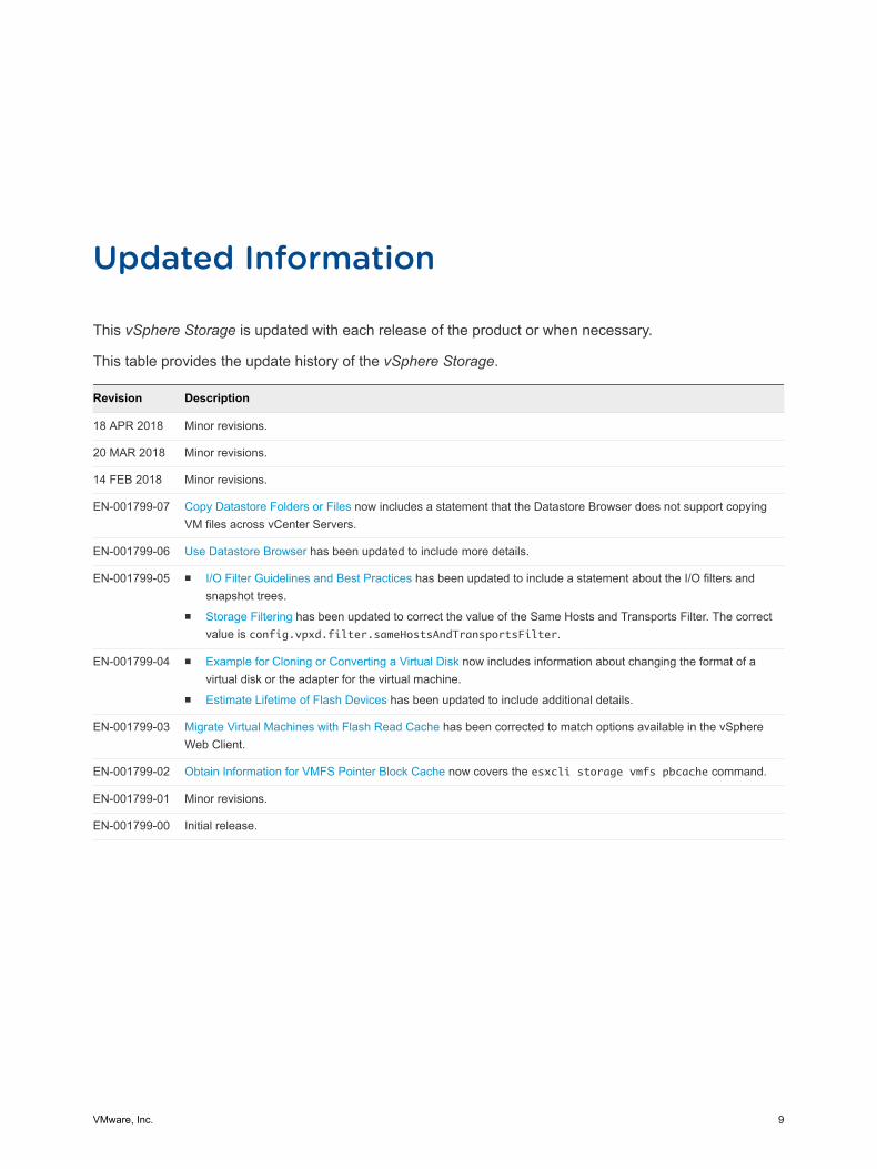
This vSphere Storage is updated with each release of the product or when necessary.
This table provides the update history of the vSphere Storage.
Revision Description
18 APR 2018 Minor revisions.
20 MAR 2018 Minor revisions.
14 FEB 2018 Minor revisions.
EN-001799-07 Copy Datastore Folders or Files now includes a statement that the Datastore Browser does not support copyingVM files across vCenter Servers.
EN-001799-06 Use Datastore Browser has been updated to include more details.
EN-001799-05 n I/O Filter Guidelines and Best Practices has been updated to include a statement about the I/O filters andsnapshot trees.
n Storage Filtering has been updated to correct the value of the Same Hosts and Transports Filter. The correctvalue is config.vpxd.filter.sameHostsAndTransportsFilter.
EN-001799-04 n Example for Cloning or Converting a Virtual Disk now includes information about changing the format of avirtual disk or the adapter for the virtual machine.
n Estimate Lifetime of Flash Devices has been updated to include additional details.
EN-001799-03 Migrate Virtual Machines with Flash Read Cache has been corrected to match options available in the vSphereWeb Client.
EN-001799-02 Obtain Information for VMFS Pointer Block Cache now covers the esxcli storage vmfs pbcache command.
EN-001799-01 Minor revisions.
EN-001799-00 Initial release.
VMware, Inc. 9
Introduction to Storage 1This introduction describes storage options available in vSphere and explains how to configure your hostso that it can use and manage different types of storage.
This chapter includes the following topics:
n Storage Virtualization
n Types of Physical Storage
n Target and Device Representations
n Storage Device Characteristics
n Supported Storage Adapters
n Datastore Characteristics
n How Virtual Machines Access Storage
n Comparing Types of Storage
Storage VirtualizationvSphere storage virtualization supports such capabilities as virtual machines, Virtual SAN, VirtualVolumes, policy-based storage managements, and so on.
ESXi provides host-level storage virtualization, which logically abstracts the physical storage layer fromvirtual machines. An ESXi virtual machine uses a virtual disk to store its operating system, program files,and other data associated with its activities. A virtual disk is a large physical file, or a set of files, that canbe copied, moved, archived, and backed up as easily as any other file. You can configure virtualmachines with multiple virtual disks.
To access virtual disks, a virtual machine uses virtual SCSI controllers. These virtual controllers includeBusLogic Parallel, LSI Logic Parallel, LSI Logic SAS, and VMware Paravirtual. These controllers are theonly types of SCSI controllers that a virtual machine can see and access.
Each virtual disk resides on a datastore that is deployed on physical storage. From the standpoint of thevirtual machine, each virtual disk appears as if it were a SCSI drive connected to a SCSI controller.Whether the actual physical storage is being accessed through storage or network adapters on the host istypically transparent to the guest operating system and to applications running on the virtual machine.
VMware, Inc. 10
In addition to virtual disks, vSphere offers a mechanism called raw device mapping (RDM). RDM is usefulwhen a guest operating system inside a virtual machine requires direct access to a storage device. Forinformation about RDMs, see Chapter 18 Raw Device Mapping.
Other storage virtualization capabilities that vSphere provides include Virtual SAN, Virtual Flash, VirtualVolumes, and policy-based storage management. For information about Virtual SAN, see theAdministering VMware Virtual SAN.
Types of Physical StorageThe ESXi storage management process starts with storage space that your storage administratorpreallocates on different storage systems.
ESXi supports the following types of storage:
Local Storage Stores virtual machine files on internal or directly connected externalstorage disks.
Networked Storage Stores virtual machine files on external storage disks or arrays attached toyour host through a direct connection or through a high-speed network.
Local StorageLocal storage can be internal hard disks located inside your ESXi host, or it can be external storagesystems located outside and connected to the host directly through protocols such as SAS or SATA.
Local storage does not require a storage network to communicate with your host. You need a cableconnected to the storage unit and, when required, a compatible HBA in your host.
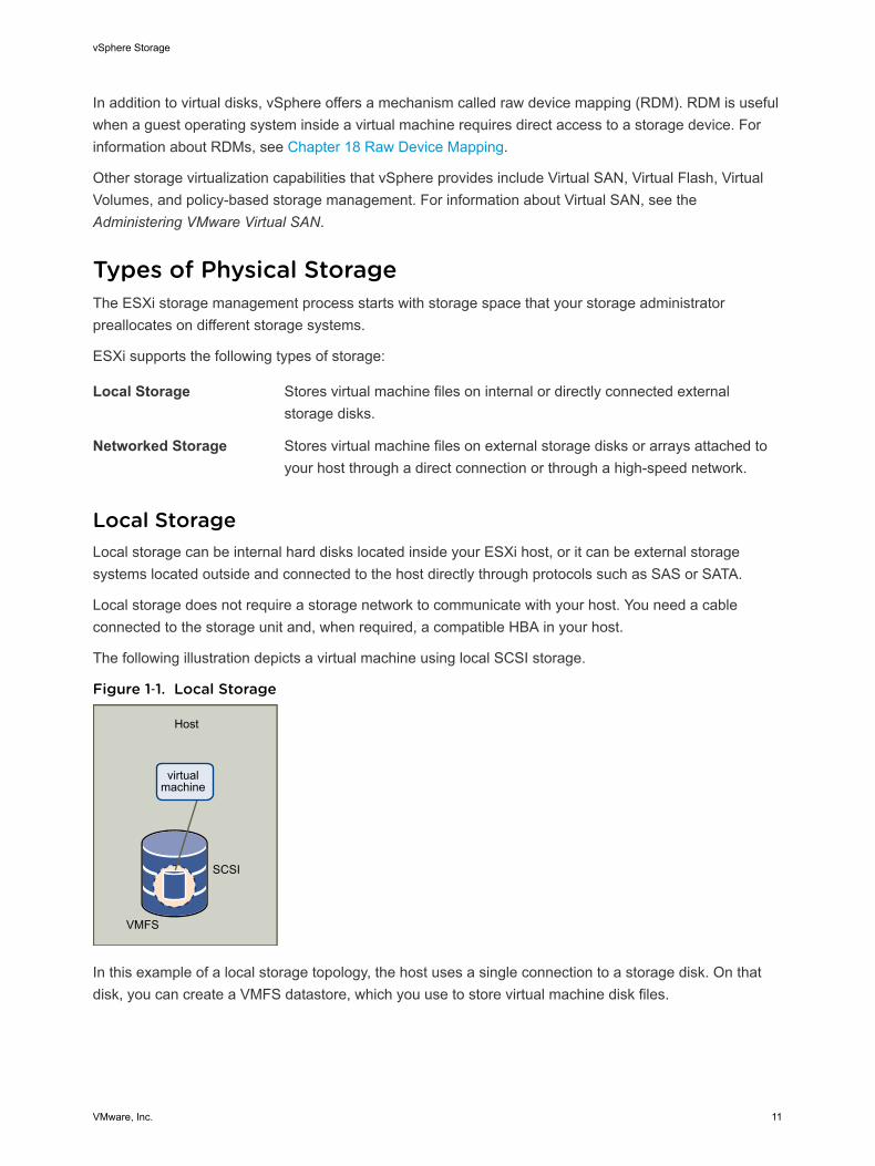
The following illustration depicts a virtual machine using local SCSI storage.
Figure 1‑1. Local Storage
Host
VMFS
SCSI
virtualmachine
In this example of a local storage topology, the host uses a single connection to a storage disk. On thatdisk, you can create a VMFS datastore, which you use to store virtual machine disk files.
vSphere Storage
VMware, Inc. 11
Although this storage configuration is possible, it is not a recommended topology. Using singleconnections between storage arrays and hosts creates single points of failure (SPOF) that can causeinterruptions when a connection becomes unreliable or fails. However, because the majority of localstorage devices do not support multiple connections, you cannot use multiple paths to access localstorage.
ESXi supports a variety of local storage devices, including SCSI, IDE, SATA, USB, and SAS storagesystems. Regardless of the type of storage you use, your host hides a physical storage layer from virtualmachines.
Note You cannot use IDE/ATA or USB drives to store virtual machines.
Local storage does not support sharing across multiple hosts. Only one host has access to a datastore ona local storage device. As a result, although you can use local storage to create virtual machines, itprevents you from using VMware features that require shared storage, such as HA and vMotion.
However, if you use a cluster of hosts that have just local storage devices, you can implement VirtualSAN. Virtual SAN transforms local storage resources into software-defined shared storage and allows youto use features that require shared storage. For details, see the Administering VMware Virtual SANdocumentation.
Networked StorageNetworked storage consists of external storage systems that your ESXi host uses to store virtual machinefiles remotely. Typically, the host accesses these systems over a high-speed storage network.
Networked storage devices are shared. Datastores on networked storage devices can be accessed bymultiple hosts concurrently. ESXi supports multiple networked storage technologies.
In addition to traditional networked storage that this topic covers, VMware supports virtualized sharedstorage, such as Virtual SAN. Virtual SAN transforms internal storage resources of your ESXi hosts intoshared storage that provides such capabilities as High Availability and vMotion for virtual machines. Fordetails, see the Administering VMware Virtual SAN documentation.
Note The same LUN cannot be presented to an ESXi host or multiple hosts through different storageprotocols. To access the LUN, hosts must always use a single protocol, for example, either Fibre Channelonly or iSCSI only.
Fibre Channel (FC)Stores virtual machine files remotely on an FC storage area network (SAN). FC SAN is a specializedhigh-speed network that connects your hosts to high-performance storage devices. The network usesFibre Channel protocol to transport SCSI traffic from virtual machines to the FC SAN devices.
To connect to the FC SAN, your host should be equipped with Fibre Channel host bus adapters (HBAs).Unless you use Fibre Channel direct connect storage, you need Fibre Channel switches to route storagetraffic. If your host contains FCoE (Fibre Channel over Ethernet) adapters, you can connect to yourshared Fibre Channel devices by using an Ethernet network.
vSphere Storage
VMware, Inc. 12
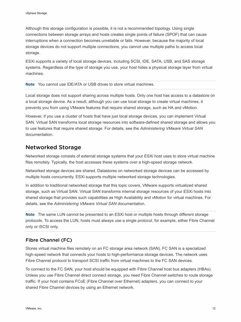
Fibre Channel Storage depicts virtual machines using Fibre Channel storage.
Figure 1‑2. Fibre Channel Storage
fibre array
VMFS
virtualmachine
SAN
fibrechannel
HBA
Host
In this configuration, a host connects to a SAN fabric, which consists of Fibre Channel switches andstorage arrays, using a Fibre Channel adapter. LUNs from a storage array become available to the host.You can access the LUNs and create datastores for your storage needs. The datastores use the VMFSformat.
For specific information on setting up the Fibre Channel SAN, see Chapter 3 Using ESXi with FibreChannel SAN.
Internet SCSI (iSCSI)Stores virtual machine files on remote iSCSI storage devices. iSCSI packages SCSI storage traffic intothe TCP/IP protocol so that it can travel through standard TCP/IP networks instead of the specialized FCnetwork. With an iSCSI connection, your host serves as the initiator that communicates with a target,located in remote iSCSI storage systems.
ESXi offers the following types of iSCSI connections:
Hardware iSCSI Your host connects to storage through a third-party adapter capable ofoffloading the iSCSI and network processing. Hardware adapters can bedependent and independent.
Software iSCSI Your host uses a software-based iSCSI initiator in the VMkernel to connectto storage. With this type of iSCSI connection, your host needs only astandard network adapter for network connectivity.
You must configure iSCSI initiators for the host to access and display iSCSI storage devices.
vSphere Storage
VMware, Inc. 13
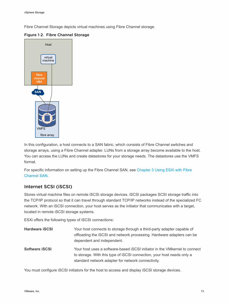
iSCSI Storage depicts different types of iSCSI initiators.
Figure 1‑3. iSCSI Storage
iSCSI array
VMFS
virtualmachine
virtualmachine
LAN LAN
iSCSI HBA ethernet
NIC
Host
softwareadapter
In the left example, the host uses the hardware iSCSI adapter to connect to the iSCSI storage system.
In the right example, the host uses a software iSCSI adapter and an Ethernet NIC to connect to the iSCSIstorage.
iSCSI storage devices from the storage system become available to the host. You can access the storagedevices and create VMFS datastores for your storage needs.
For specific information on setting up the iSCSI SAN, see Chapter 9 Using ESXi with iSCSI SAN.
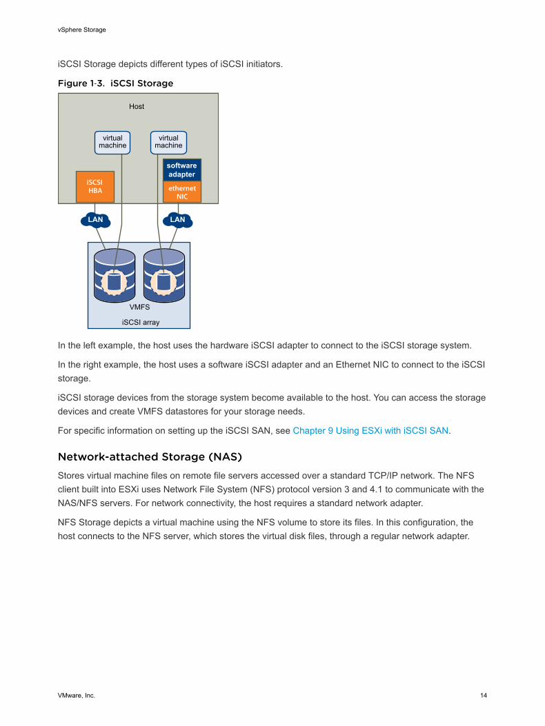
Network-attached Storage (NAS)Stores virtual machine files on remote file servers accessed over a standard TCP/IP network. The NFSclient built into ESXi uses Network File System (NFS) protocol version 3 and 4.1 to communicate with theNAS/NFS servers. For network connectivity, the host requires a standard network adapter.
NFS Storage depicts a virtual machine using the NFS volume to store its files. In this configuration, thehost connects to the NFS server, which stores the virtual disk files, through a regular network adapter.
vSphere Storage
VMware, Inc. 14
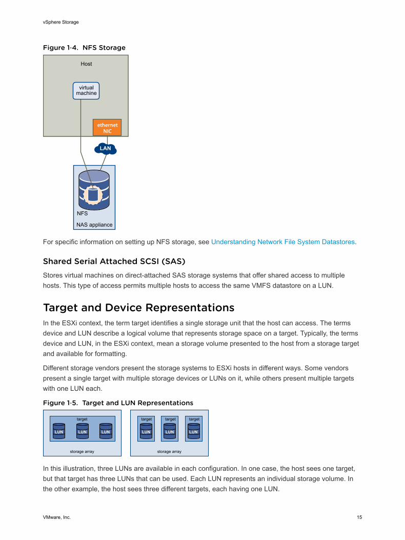
Figure 1‑4. NFS Storage
NAS appliance
NFS
virtualmachine
LAN
ethernetNIC
Host
For specific information on setting up NFS storage, see Understanding Network File System Datastores.
Shared Serial Attached SCSI (SAS)Stores virtual machines on direct-attached SAS storage systems that offer shared access to multiplehosts. This type of access permits multiple hosts to access the same VMFS datastore on a LUN.
Target and Device RepresentationsIn the ESXi context, the term target identifies a single storage unit that the host can access. The termsdevice and LUN describe a logical volume that represents storage space on a target. Typically, the termsdevice and LUN, in the ESXi context, mean a storage volume presented to the host from a storage targetand available for formatting.
Different storage vendors present the storage systems to ESXi hosts in different ways. Some vendorspresent a single target with multiple storage devices or LUNs on it, while others present multiple targetswith one LUN each.
Figure 1‑5. Target and LUN Representations
storage array
target
LUN LUN LUN
storage array
target target target
LUN LUN LUN
In this illustration, three LUNs are available in each configuration. In one case, the host sees one target,but that target has three LUNs that can be used. Each LUN represents an individual storage volume. Inthe other example, the host sees three different targets, each having one LUN.
vSphere Storage
VMware, Inc. 15
Targets that are accessed through the network have unique names that are provided by the storagesystems. The iSCSI targets use iSCSI names, while Fibre Channel targets use World Wide Names(WWNs).
Note ESXi does not support accessing the same LUN through different transport protocols, such asiSCSI and Fibre Channel.
A device, or LUN, is identified by its UUID name. If a LUN is shared by multiple hosts, it must bepresented to all hosts with the same UUID.
Storage Device CharacteristicsYou can display all storage devices or LUNs available to the host, including all local and networkeddevices. If you use third-party multipathing plug-ins, the storage devices available through the plug-insalso appear on the list.
For each storage adapter, you can display a separate list of storage devices available for this adapter.
Generally, when you review storage devices, you see the following information.
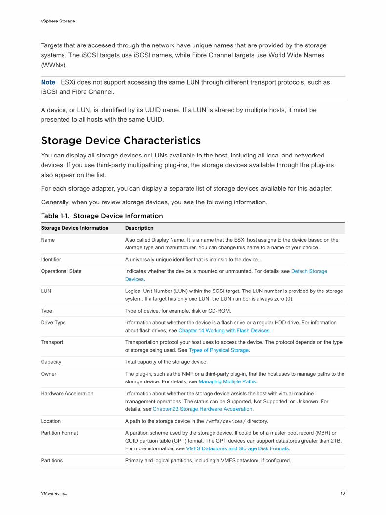
Table 1‑1. Storage Device Information
Storage Device Information Description
Name Also called Display Name. It is a name that the ESXi host assigns to the device based on thestorage type and manufacturer. You can change this name to a name of your choice.
Identifier A universally unique identifier that is intrinsic to the device.
Operational State Indicates whether the device is mounted or unmounted. For details, see Detach StorageDevices.
LUN Logical Unit Number (LUN) within the SCSI target. The LUN number is provided by the storagesystem. If a target has only one LUN, the LUN number is always zero (0).
Type Type of device, for example, disk or CD-ROM.
Drive Type Information about whether the device is a flash drive or a regular HDD drive. For informationabout flash drives, see Chapter 14 Working with Flash Devices.
Transport Transportation protocol your host uses to access the device. The protocol depends on the typeof storage being used. See Types of Physical Storage.
Capacity Total capacity of the storage device.
Owner The plug-in, such as the NMP or a third-party plug-in, that the host uses to manage paths to thestorage device. For details, see Managing Multiple Paths.
Hardware Acceleration Information about whether the storage device assists the host with virtual machinemanagement operations. The status can be Supported, Not Supported, or Unknown. Fordetails, see Chapter 23 Storage Hardware Acceleration.
Location A path to the storage device in the /vmfs/devices/ directory.
Partition Format A partition scheme used by the storage device. It could be of a master boot record (MBR) orGUID partition table (GPT) format. The GPT devices can support datastores greater than 2TB.For more information, see VMFS Datastores and Storage Disk Formats.
Partitions Primary and logical partitions, including a VMFS datastore, if configured.
vSphere Storage
VMware, Inc. 16
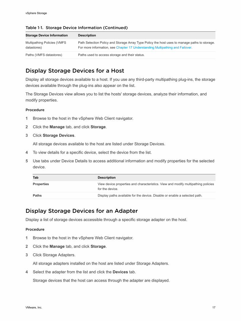
Table 1‑1. Storage Device Information (Continued)
Storage Device Information Description
Multipathing Policies (VMFSdatastores)
Path Selection Policy and Storage Array Type Policy the host uses to manage paths to storage.For more information, see Chapter 17 Understanding Multipathing and Failover.
Paths (VMFS datastores) Paths used to access storage and their status.
Display Storage Devices for a HostDisplay all storage devices available to a host. If you use any third-party multipathing plug-ins, the storagedevices available through the plug-ins also appear on the list.
The Storage Devices view allows you to list the hosts' storage devices, analyze their information, andmodify properties.
Procedure
1 Browse to the host in the vSphere Web Client navigator.
2 Click the Manage tab, and click Storage.
3 Click Storage Devices.
All storage devices available to the host are listed under Storage Devices.
4 To view details for a specific device, select the device from the list.
5 Use tabs under Device Details to access additional information and modify properties for the selecteddevice.
Tab Description
Properties View device properties and characteristics. View and modify multipathing policiesfor the device.
Paths Display paths available for the device. Disable or enable a selected path.
Display Storage Devices for an AdapterDisplay a list of storage devices accessible through a specific storage adapter on the host.
Procedure
1 Browse to the host in the vSphere Web Client navigator.
2 Click the Manage tab, and click Storage.
3 Click Storage Adapters.
All storage adapters installed on the host are listed under Storage Adapters.
4 Select the adapter from the list and click the Devices tab.
Storage devices that the host can access through the adapter are displayed.
vSphere Storage
VMware, Inc. 17
Supported Storage AdaptersStorage adapters provide connectivity for your ESXi host to a specific storage unit or network.
ESXi supports different classes of adapters, including SCSI, iSCSI, RAID, Fibre Channel, Fibre Channelover Ethernet (FCoE), and Ethernet. ESXi accesses the adapters directly through device drivers in theVMkernel.
Depending on the type of storage you use, you might need to enable and configure a storage adapter onyour host.
For information on setting up software FCoE adapters, see Chapter 5 Configuring Fibre Channel overEthernet.
For information on configuring different types of iSCSI adapters, see Chapter 10 Configuring iSCSIAdapters and Storage.
Storage Adapter CharacteristicsThe host uses storage adapters to access different storage devices. You can display details for theavailable storage adapters and review their information.
You must enable certain adapters, for example software iSCSI or FCoE, before you can view theirinformation.
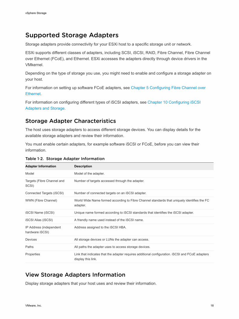
Table 1‑2. Storage Adapter Information
Adapter Information Description
Model Model of the adapter.
Targets (Fibre Channel andSCSI)
Number of targets accessed through the adapter.
Connected Targets (iSCSI) Number of connected targets on an iSCSI adapter.
WWN (Fibre Channel) World Wide Name formed according to Fibre Channel standards that uniquely identifies the FCadapter.
iSCSI Name (iSCSI) Unique name formed according to iSCSI standards that identifies the iSCSI adapter.
iSCSI Alias (iSCSI) A friendly name used instead of the iSCSI name.
IP Address (independenthardware iSCSI)
Address assigned to the iSCSI HBA.
Devices All storage devices or LUNs the adapter can access.
Paths All paths the adapter uses to access storage devices.
Properties Link that indicates that the adapter requires additional configuration. iSCSI and FCoE adaptersdisplay this link.
View Storage Adapters InformationDisplay storage adapters that your host uses and review their information.
vSphere Storage
VMware, Inc. 18
Procedure
1 Browse to the host in the vSphere Web Client navigator.
2 Click the Manage tab, and click Storage.
3 Click Storage Adapters.
4 To view details for a specific adapter, select the adapter from the list.
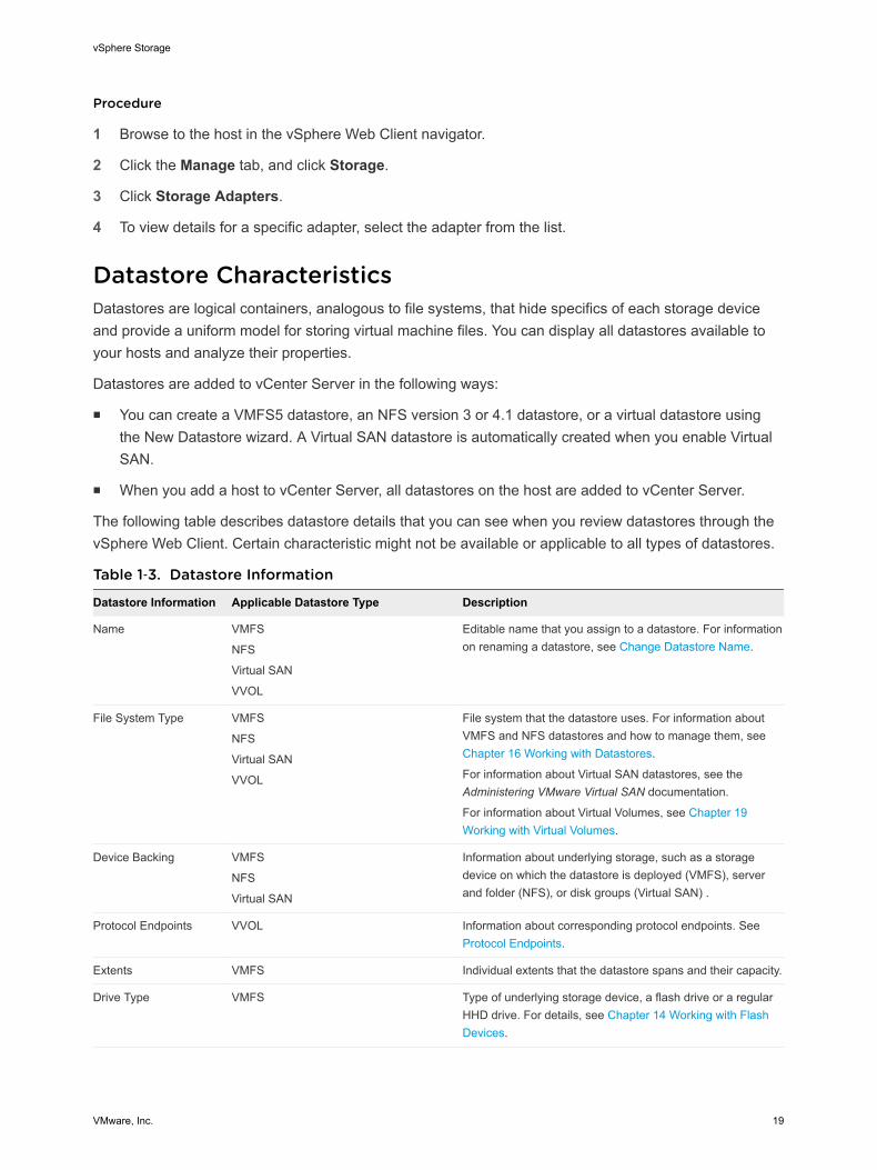
Datastore CharacteristicsDatastores are logical containers, analogous to file systems, that hide specifics of each storage deviceand provide a uniform model for storing virtual machine files. You can display all datastores available toyour hosts and analyze their properties.
Datastores are added to vCenter Server in the following ways:
n You can create a VMFS5 datastore, an NFS version 3 or 4.1 datastore, or a virtual datastore usingthe New Datastore wizard. A Virtual SAN datastore is automatically created when you enable VirtualSAN.
n When you add a host to vCenter Server, all datastores on the host are added to vCenter Server.
The following table describes datastore details that you can see when you review datastores through thevSphere Web Client. Certain characteristic might not be available or applicable to all types of datastores.
Table 1‑3. Datastore Information
Datastore Information Applicable Datastore Type Description
Name VMFS
NFS
Virtual SAN
VVOL
Editable name that you assign to a datastore. For informationon renaming a datastore, see Change Datastore Name.
File System Type VMFS
NFS
Virtual SAN
VVOL
File system that the datastore uses. For information aboutVMFS and NFS datastores and how to manage them, see Chapter 16 Working with Datastores.
For information about Virtual SAN datastores, see theAdministering VMware Virtual SAN documentation.
For information about Virtual Volumes, see Chapter 19Working with Virtual Volumes.
Device Backing VMFS
NFS
Virtual SAN
Information about underlying storage, such as a storagedevice on which the datastore is deployed (VMFS), serverand folder (NFS), or disk groups (Virtual SAN) .
Protocol Endpoints VVOL Information about corresponding protocol endpoints. See Protocol Endpoints.
Extents VMFS Individual extents that the datastore spans and their capacity.
Drive Type VMFS Type of underlying storage device, a flash drive or a regularHHD drive. For details, see Chapter 14 Working with FlashDevices.
vSphere Storage
VMware, Inc. 19
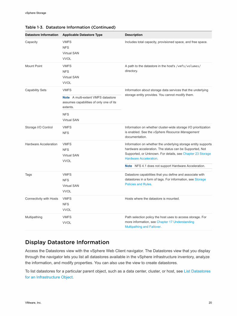
Table 1‑3. Datastore Information (Continued)
Datastore Information Applicable Datastore Type Description
Capacity VMFS
NFS
Virtual SAN
VVOL
Includes total capacity, provisioned space, and free space.
Mount Point VMFS
NFS
Virtual SAN
VVOL
A path to the datastore in the host's /vmfs/volumes/directory.
Capability Sets VMFS
Note A multi-extent VMFS datastoreassumes capabilities of only one of itsextents.
NFS
Virtual SAN
Information about storage data services that the underlyingstorage entity provides. You cannot modify them.
Storage I/O Control VMFS
NFS
Information on whether cluster-wide storage I/O prioritizationis enabled. See the vSphere Resource Managementdocumentation.
Hardware Acceleration VMFS
NFS
Virtual SAN
VVOL
Information on whether the underlying storage entity supportshardware acceleration. The status can be Supported, NotSupported, or Unknown. For details, see Chapter 23 StorageHardware Acceleration.
Note NFS 4.1 does not support Hardware Acceleration.
Tags VMFS
NFS
Virtual SAN
VVOL
Datastore capabilities that you define and associate withdatastores in a form of tags. For information, see StoragePolicies and Rules.
Connectivity with Hosts VMFS
NFS
VVOL
Hosts where the datastore is mounted.
Multipathing VMFS
VVOL
Path selection policy the host uses to access storage. Formore information, see Chapter 17 UnderstandingMultipathing and Failover.
Display Datastore InformationAccess the Datastores view with the vSphere Web Client navigator. The Datastores view that you displaythrough the navigator lets you list all datastores available in the vSphere infrastructure inventory, analyzethe information, and modify properties. You can also use the view to create datastores.
To list datastores for a particular parent object, such as a data center, cluster, or host, see List Datastoresfor an Infrastructure Object.
vSphere Storage
VMware, Inc. 20

Procedure
1 In the vSphere Web Client navigator, select vCenter Inventory Lists > Datastores
Datastores that are available in the inventory appear in the center Datastores panel.
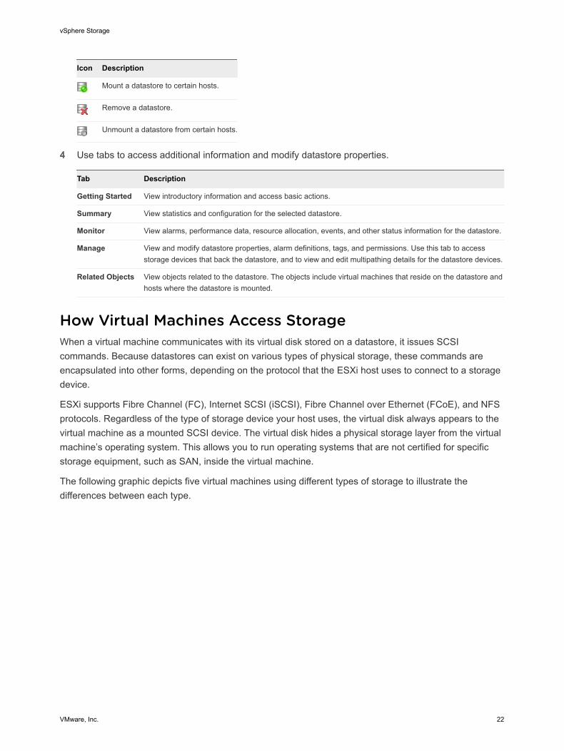
2 Use the icons to create a datastore or to perform basic tasks for a selected datastore.
Icon Description
Create a datastore.
Increase datastore capacity.
Mount a datastore to certain hosts.
Remove a datastore.
Unmount a datastore from certain hosts.
3 To view specific datastore details, click a selected datastore.
4 Use tabs to access additional information and modify datastore properties.
Tab Description
Getting Started View introductory information and access basic actions.
Summary View statistics and configuration for the selected datastore.
Monitor View alarms, performance data, resource allocation, events, and other status information for the datastore.
Manage View and modify datastore properties, alarm definitions, tags, and permissions. Use this tab to accessstorage devices that back the datastore, and to view and edit multipathing details for the datastore devices.
Related Objects View objects related to the datastore. The objects include virtual machines that reside on the datastore andhosts where the datastore is mounted.
List Datastores for an Infrastructure ObjectDisplay datastores for a specific parent object, such as a data center, cluster, or host.
Procedure
1 Use the vSphere Web Client object navigator to browse to an object that is a valid parent object of adatastore, such as a data center, cluster, or host.
2 Click the Related Objects tab and click Datastores.
If any datastores are configured for this object, they appear in the center Datastores panel.
3 Use the icons to create a datastore or to perform basic tasks for a selected datastore.
Icon Description
Create a datastore.
Increase datastore capacity.
vSphere Storage
VMware, Inc. 21
Icon Description
Mount a datastore to certain hosts.
Remove a datastore.
Unmount a datastore from certain hosts.
4 Use tabs to access additional information and modify datastore properties.
Tab Description
Getting Started View introductory information and access basic actions.
Summary View statistics and configuration for the selected datastore.
Monitor View alarms, performance data, resource allocation, events, and other status information for the datastore.
Manage View and modify datastore properties, alarm definitions, tags, and permissions. Use this tab to accessstorage devices that back the datastore, and to view and edit multipathing details for the datastore devices.
Related Objects View objects related to the datastore. The objects include virtual machines that reside on the datastore andhosts where the datastore is mounted.
How Virtual Machines Access StorageWhen a virtual machine communicates with its virtual disk stored on a datastore, it issues SCSIcommands. Because datastores can exist on various types of physical storage, these commands areencapsulated into other forms, depending on the protocol that the ESXi host uses to connect to a storagedevice.
ESXi supports Fibre Channel (FC), Internet SCSI (iSCSI), Fibre Channel over Ethernet (FCoE), and NFSprotocols. Regardless of the type of storage device your host uses, the virtual disk always appears to thevirtual machine as a mounted SCSI device. The virtual disk hides a physical storage layer from the virtualmachine’s operating system. This allows you to run operating systems that are not certified for specificstorage equipment, such as SAN, inside the virtual machine.
The following graphic depicts five virtual machines using different types of storage to illustrate thedifferences between each type.
vSphere Storage
VMware, Inc. 22
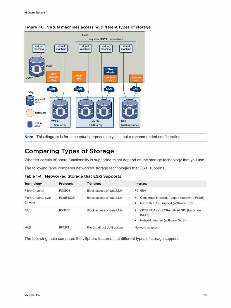
Figure 1‑6. Virtual machines accessing different types of storage
iSCSI array NAS appliancefibre array
Host
VMFS
SCSI
VMFS VMFS NFS
virtualmachine
virtualmachine
virtualmachine
virtualmachine
virtualmachine
SAN LAN LAN LAN
iSCSI HBA
fibrechannel
HBAethernet
NICethernet
NIC
softwareadapter
requires TCP/IP connectivity
Key
physicaldisk
datastore
virtualdisk
Note This diagram is for conceptual purposes only. It is not a recommended configuration.
Comparing Types of StorageWhether certain vSphere functionality is supported might depend on the storage technology that you use.
The following table compares networked storage technologies that ESXi supports.
Table 1‑4. Networked Storage that ESXi Supports
Technology Protocols Transfers Interface
Fibre Channel FC/SCSI Block access of data/LUN FC HBA
Fibre Channel overEthernet
FCoE/SCSI Block access of data/LUN n Converged Network Adapter (hardware FCoE)n NIC with FCoE support (software FCoE)
iSCSI IP/SCSI Block access of data/LUN n iSCSI HBA or iSCSI-enabled NIC (hardwareiSCSI)
n Network adapter (software iSCSI)
NAS IP/NFS File (no direct LUN access) Network adapter
The following table compares the vSphere features that different types of storage support.
vSphere Storage
VMware, Inc. 23
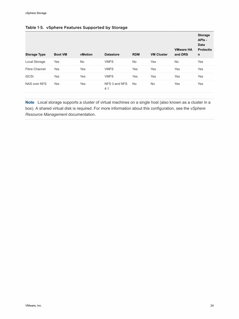
Table 1‑5. vSphere Features Supported by Storage
Storage Type Boot VM vMotion Datastore RDM VM ClusterVMware HAand DRS
StorageAPIs -DataProtection
Local Storage Yes No VMFS No Yes No Yes
Fibre Channel Yes Yes VMFS Yes Yes Yes Yes
iSCSI Yes Yes VMFS Yes Yes Yes Yes
NAS over NFS Yes Yes NFS 3 and NFS4.1
No No Yes Yes
Note Local storage supports a cluster of virtual machines on a single host (also known as a cluster in abox). A shared virtual disk is required. For more information about this configuration, see the vSphereResource Management documentation.
vSphere Storage
VMware, Inc. 24
Overview of Using ESXi with aSAN 2Using ESXi with a SAN improves flexibility, efficiency, and reliability. Using ESXi with a SAN also supportscentralized management, failover, and load balancing technologies.
The following are benefits of using ESXi with a SAN:
n You can store data securely and configure multiple paths to your storage, eliminating a single point offailure.
n Using a SAN with ESXi systems extends failure resistance to the server. When you use SAN storage,all applications can instantly be restarted on another host after the failure of the original host.
n You can perform live migration of virtual machines using VMware vMotion.
n Use VMware High Availability (HA) in conjunction with a SAN to restart virtual machines in their lastknown state on a different server if their host fails.
n Use VMware Fault Tolerance (FT) to replicate protected virtual machines on two different hosts.Virtual machines continue to function without interruption on the secondary host if the primary onefails.
n Use VMware Distributed Resource Scheduler (DRS) to migrate virtual machines from one host toanother for load balancing. Because storage is on a shared SAN array, applications continue runningseamlessly.
n If you use VMware DRS clusters, put an ESXi host into maintenance mode to have the systemmigrate all running virtual machines to other ESXi hosts. You can then perform upgrades or othermaintenance operations on the original host.
The portability and encapsulation of VMware virtual machines complements the shared nature of thisstorage. When virtual machines are located on SAN-based storage, you can quickly shut down a virtualmachine on one server and power it up on another server, or suspend it on one server and resumeoperation on another server on the same network. This ability allows you to migrate computing resourceswhile maintaining consistent shared access.
This chapter includes the following topics:
n ESXi and SAN Use Cases
n Specifics of Using SAN Storage with ESXi
n ESXi Hosts and Multiple Storage Arrays
VMware, Inc. 25
n Making LUN Decisions
n Choosing Virtual Machine Locations
n Layered Applications
n Third-Party Management Applications
n SAN Storage Backup Considerations
ESXi and SAN Use CasesWhen used with a SAN, ESXi can benefit from multiple vSphere features, including Storage vMotion,Distributed Resource Scheduler (DRS), High Availability, and so on.
Using ESXi in conjunction with a SAN is effective for the following tasks:
Storage consolidationand simplification ofstorage layout
If you are working with multiple hosts, and each host is running multiplevirtual machines, the storage on the hosts is no longer sufficient andexternal storage is required. Choose a SAN for external storage to providea simpler system architecture along with other benefits.
Maintenance with zerodowntime
When performing ESXi host or infrastructure maintenance, use vMotion tomigrate virtual machines to other host. If shared storage is on the SAN, youcan perform maintenance without interruptions to the users of the virtualmachines. Virtual machine working processes continue throughout amigration.
Load balancing You can add a host to a DRS cluster, and the host's resources become partof the cluster's resources. The distribution and usage of CPU and memoryresources for all hosts and virtual machines in the cluster are continuouslymonitored. DRS compares these metrics to an ideal resource utilization.Ideal utilization takes into account the attributes of the cluster's resourcepools and virtual machines, the current demand, and the imbalance target.It then performs (or recommends) virtual machine migrations accordingly.
Disaster recovery You can use VMware High Availability to configure multiple ESXi hosts as acluster to provide rapid recovery from outages and cost-effective highavailability for applications running in virtual machines.
Simplified arraymigrations and storageupgrades
When you purchase new storage systems or arrays, use Storage vMotionto perform live automated migration of virtual machine disk files fromexisting storage to their new destination without interruptions to the users ofthe virtual machines.
Specifics of Using SAN Storage with ESXiUsing a SAN in conjunction with an ESXi host differs from traditional SAN usage in a variety of ways.
vSphere Storage
VMware, Inc. 26
When you use SAN storage with ESXi, keep in mind the following considerations:
n You cannot use SAN administration tools to directly access operating systems of virtual machines thatuse the storage. With traditional tools, you can monitor only the VMware ESXi operating system. Youuse the vSphere Web Client to monitor virtual machines.
n The HBA visible to the SAN administration tools is part of the ESXi system, not part of the virtualmachine.
n Typically, your ESXi system performs multipathing for you.
ESXi Hosts and Multiple Storage ArraysAn ESXi host can access storage devices presented from multiple storage arrays, including arrays fromdifferent vendors.
When you use multiple arrays from different vendors, the following considerations apply:
n If your host uses the same Storage Array Type Plugin (SATP) for multiple arrays, be careful when youneed to change the default Path Selection Policy (PSP) for that SATP. The change will apply to allarrays. For information on SATPs and PSPs, see Chapter 17 Understanding Multipathing andFailover.
n Some storage arrays make recommendations on queue depth and other settings. Typically, thesesettings are configured globally at the ESXi host level. Making a change for one array impacts otherarrays that present LUNs to the host. For information on changing queue depth, see the VMwareknowledge base article at http://kb.vmware.com/kb/1267.
n Use single-initiator-single-target zoning when zoning ESXi hosts to Fibre Channel arrays. With thistype of configuration, fabric related events that occur on one array do not impact other arrays. Formore information about zoning, see Using Zoning with Fibre Channel SANs.
Making LUN DecisionsYou must plan how to set up storage for your ESXi systems before you format LUNs with VMFSdatastores.
When you make your LUN decision, keep in mind the following considerations:
n Each LUN should have the correct RAID level and storage characteristic for the applications runningin virtual machines that use the LUN.
n Each LUN must contain only one VMFS datastore.
n If multiple virtual machines access the same VMFS, use disk shares to prioritize virtual machines.
You might want fewer, larger LUNs for the following reasons:
n More flexibility to create virtual machines without asking the storage administrator for more space.
n More flexibility for resizing virtual disks, doing snapshots, and so on.
n Fewer VMFS datastores to manage.
vSphere Storage
VMware, Inc. 27
You might want more, smaller LUNs for the following reasons:
n Less wasted storage space.
n Different applications might need different RAID characteristics.
n More flexibility, as the multipathing policy and disk shares are set per LUN.
n Use of Microsoft Cluster Service requires that each cluster disk resource is in its own LUN.
n Better performance because there is less contention for a single volume.
When the storage characterization for a virtual machine is not available, there is often no simple methodto determine the number and size of LUNs to provision. You can experiment using either a predictive oradaptive scheme.
Use the Predictive Scheme to Make LUN DecisionsWhen setting up storage for ESXi systems, before creating VMFS datastores, you must decide on thesize and number of LUNs to provision. You can experiment using the predictive scheme.
Procedure
1 Provision several LUNs with different storage characteristics.
2 Create a VMFS datastore on each LUN, labeling each datastore according to its characteristics.
3 Create virtual disks to contain the data for virtual machine applications in the VMFS datastorescreated on LUNs with the appropriate RAID level for the applications' requirements.
4 Use disk shares to distinguish high-priority from low-priority virtual machines.
Note Disk shares are relevant only within a given host. The shares assigned to virtual machines onone host have no effect on virtual machines on other hosts.
5 Run the applications to determine whether virtual machine performance is acceptable.
Use the Adaptive Scheme to Make LUN DecisionsWhen setting up storage for ESXi hosts, before creating VMFS datastores, you must decide on thenumber and size of LUNS to provision. You can experiment using the adaptive scheme.
Procedure
1 Provision a large LUN (RAID 1+0 or RAID 5), with write caching enabled.
2 Create a VMFS on that LUN.
3 Create four or five virtual disks on the VMFS.
4 Run the applications to determine whether disk performance is acceptable.
If performance is acceptable, you can place additional virtual disks on the VMFS. If performance is notacceptable, create a new, large LUN, possibly with a different RAID level, and repeat the process. Usemigration so that you do not lose virtual machines data when you recreate the LUN.
vSphere Storage
VMware, Inc. 28
Choosing Virtual Machine LocationsWhen you’re working on optimizing performance for your virtual machines, storage location is animportant factor. A trade-off always exists between expensive storage that offers high performance andhigh availability and storage with lower cost and lower performance.
Storage can be divided into different tiers depending on a number of factors:
n High Tier. Offers high performance and high availability. Might offer built-in snapshots to facilitatebackups and point-in-time (PiT) restorations. Supports replication, full storage processor redundancy,and SAS drives. Uses high-cost spindles.
n Mid Tier. Offers mid-range performance, lower availability, some storage processor redundancy, andSCSI or SAS drives. May offer snapshots. Uses medium-cost spindles.
n Lower Tier. Offers low performance, little internal storage redundancy. Uses low end SCSI drives orSATA (serial low-cost spindles).
Not all applications need to be on the highest-performance, most-available storage—at least notthroughout their entire life cycle.
Note If you need some of the functionality of the high tier, such as snapshots, but do not want to pay forit, you might be able to achieve some of the high-performance characteristics in software. For example,you can create snapshots in software.
When you decide where to place a virtual machine, ask yourself these questions:
n How critical is the virtual machine?
n What are its performance and availability requirements?
n What are its PiT restoration requirements?
n What are its backup requirements?
n What are its replication requirements?
A virtual machine might change tiers throughout its life cycle because of changes in criticality or changesin technology that push higher-tier features to a lower tier. Criticality is relative and might change for avariety of reasons, including changes in the organization, operational processes, regulatory requirements,disaster planning, and so on.
Layered ApplicationsSAN administrators customarily use specialized array-based software for backup, disaster recovery, datamining, forensics, and configuration testing.
vSphere Storage
VMware, Inc. 29
Storage providers typically supply two types of advanced services for their LUNs: snapshotting andreplication.
n Snapshotting creates space with efficient copies of LUNs that share common blocks of data. Ingeneral, snapshotting is used locally on the same storage systems as the primary LUN for quickbackups, application testing, forensics, or data mining.
n Replication creates full copies of LUNs. Replicas are usually made to separate storage systems,possibly separate sites to protect against major outages that incapacitate or destroy an entire array orsite.
When you use an ESXi system in conjunction with a SAN, you must decide whether array-based or host-based tools are more suitable for your particular situation.
Array-Based (Third-Party) SolutionWhen you use an ESXi system in conjunction with a SAN, you must decide whether array-based tools aremore suitable for your particular situation.
When you consider an array-based solution, keep in mind the following points:
n Array-based solutions usually result in more comprehensive statistics. With RDMs, data always takesthe same path, which results in easier performance management.
n Security is more transparent to the storage administrator when you use an RDM and an array-basedsolution because with RDMs, virtual machines more closely resemble physical machines.
n If you use an array-based solution, physical compatibility RDMs are often used for the storage ofvirtual machines. If you do not intend to use RDMs, check the storage vendor documentation to see ifoperations on LUNs with VMFS volumes are supported. If you use array operations on VMFS LUNs,carefully read the section on resignaturing.
File-Based (VMFS) SolutionWhen you use an ESXi system in conjunction with a SAN, you must decide whether file-based tools aremore suitable for your particular situation.
When you consider a file-based solution that uses VMware tools and VMFS instead of the array tools, beaware of the following points:
n Using VMware tools and VMFS is better for provisioning. One large LUN is allocated andmultiple .vmdk files can be placed on that LUN. With an RDM, a new LUN is required for each virtualmachine.
n Snapshotting is included with your ESXi host at no extra cost.
n Using VMFS is easier for ESXi administrators.
n ESXi administrators who use the file-based solution are more independent from the SANadministrator.
vSphere Storage
VMware, Inc. 30
Third-Party Management ApplicationsYou can use third-party management applications in conjunction with your ESXi host.
Most SAN hardware is packaged with storage management software. In many cases, this software is aweb application that can be used with any web browser connected to your network. In other cases, thissoftware typically runs on the storage system or on a single server, independent of the servers that usethe SAN for storage.
Use this third-party management software for the following tasks:
n Storage array management, including LUN creation, array cache management, LUN mapping, andLUN security.
n Setting up replication, check points, snapshots, or mirroring.
If you decide to run the SAN management software on a virtual machine, you gain the benefits of runninga virtual machine, including failover using vMotion and VMware HA. Because of the additional level ofindirection, however, the management software might not be able to see the SAN. In this case, you canuse an RDM.
Note Whether a virtual machine can run management software successfully depends on the particularstorage system.
SAN Storage Backup ConsiderationsHaving a proper backup strategy is one of the most important aspects of SAN management. In the SANenvironment, backups have two goals. The first goal is to archive online data to offline media. Thisprocess is repeated periodically for all online data on a time schedule. The second goal is to provideaccess to offline data for recovery from a problem. For example, database recovery often requiresretrieval of archived log files that are not currently online.
Scheduling a backup depends on a number of factors:
n Identification of critical applications that require more frequent backup cycles within a given period oftime.
n Recovery point and recovery time goals. Consider how precise your recovery point needs to be, andhow long you are willing to wait for it.
n The rate of change (RoC) associated with the data. For example, if you are usingsynchronous/asynchronous replication, the RoC affects the amount of bandwidth required betweenthe primary and secondary storage devices.
n Overall impact on SAN environment, storage performance (while backing up), and other applications.
n Identification of peak traffic periods on the SAN (backups scheduled during those peak periods canslow the applications and the backup process).
n Time to schedule all backups within the data center.
vSphere Storage
VMware, Inc. 31
n Time it takes to back up an individual application.
n Resource availability for archiving data; usually offline media access (tape).
Include a recovery-time objective for each application when you design your backup strategy. That is,consider the time and resources necessary to perform a backup. For example, if a scheduled backupstores so much data that recovery requires a considerable amount of time, examine the scheduledbackup. Perform the backup more frequently, so that less data is backed up at a time and the recoverytime decreases.
If a particular application requires recovery within a certain time frame, the backup process needs toprovide a time schedule and specific data processing to meet this requirement. Fast recovery can requirethe use of recovery volumes that reside on online storage to minimize or eliminate the need to accessslow offline media for missing data components.
Using Third-Party Backup PackagesYou can use third-party backup solutions to protect system, application, and user data in your virtualmachines.
VMware offers the Storage APIs - Data Protection to work in conjunction with third-party products. Whenusing the APIs, third-party software can perform backups without loading ESXi hosts with the processingof backup tasks.
The third-party products using the Storage APIs - Data Protection can perform the following backup tasks:
n Perform full, differential, and incremental image backup and restore of virtual machines.
n Perform file-level backup of virtual machines that use supported Windows and Linux operatingsystems.
n Ensure data consistency by using Microsoft Volume Shadow Copy Services (VSS) for virtualmachines that run supported Microsoft Windows operating systems.
Because the Storage APIs - Data Protection leverage the snapshot capabilities of VMFS, backups thatyou can perform do not require downtime for virtual machines. These backups are nondisruptive, can beperformed at any time, and do not need extended backup windows.
For information about the Storage APIs - Data Protection and integration with backup products, see theVMware Web site or contact you backup vendor.
vSphere Storage
VMware, Inc. 32
Using ESXi with Fibre ChannelSAN 3When you set up ESXi hosts to use FC SAN storage arrays, special considerations are necessary. Thissection provides introductory information about how to use ESXi with a FC SAN array.
This chapter includes the following topics:
n Fibre Channel SAN Concepts
n Using Zoning with Fibre Channel SANs
n How Virtual Machines Access Data on a Fibre Channel SAN
Fibre Channel SAN ConceptsIf you are an ESXi administrator planning to set up hosts to work with SANs, you must have a workingknowledge of SAN concepts. You can find information about SANs in print and on the Internet. Becausethis industry changes constantly, check these resources frequently.
If you are new to SAN technology, familiarize yourself with the basic terminology.
A storage area network (SAN) is a specialized high-speed network that connects computer systems, orhost servers, to high performance storage subsystems. The SAN components include host bus adapters(HBAs) in the host servers, switches that help route storage traffic, cables, storage processors (SPs), andstorage disk arrays.
A SAN topology with at least one switch present on the network forms a SAN fabric.
To transfer traffic from host servers to shared storage, the SAN uses the Fibre Channel (FC) protocol thatpackages SCSI commands into Fibre Channel frames.
To restrict server access to storage arrays not allocated to that server, the SAN uses zoning. Typically,zones are created for each group of servers that access a shared group of storage devices and LUNs.Zones define which HBAs can connect to which SPs. Devices outside a zone are not visible to thedevices inside the zone.
Zoning is similar to LUN masking, which is commonly used for permission management. LUN masking isa process that makes a LUN available to some hosts and unavailable to other hosts.
When transferring data between the host server and storage, the SAN uses a technique known asmultipathing. Multipathing allows you to have more than one physical path from the ESXi host to a LUNon a storage system.
VMware, Inc. 33
Generally, a single path from a host to a LUN consists of an HBA, switch ports, connecting cables, andthe storage controller port. If any component of the path fails, the host selects another available path forI/O. The process of detecting a failed path and switching to another is called path failover.
Ports in Fibre Channel SANIn the context of this document, a port is the connection from a device into the SAN. Each node in theSAN, such as a host, a storage device, or a fabric component has one or more ports that connect it to theSAN. Ports are identified in a number of ways.
WWPN (World WidePort Name)
A globally unique identifier for a port that allows certain applications toaccess the port. The FC switches discover the WWPN of a device or hostand assign a port address to the device.
Port_ID (or portaddress)
Within a SAN, each port has a unique port ID that serves as the FCaddress for the port. This unique ID enables routing of data through theSAN to that port. The FC switches assign the port ID when the device logsin to the fabric. The port ID is valid only while the device is logged on.
When N-Port ID Virtualization (NPIV) is used, a single FC HBA port (N-port) can register with the fabric byusing several WWPNs. This method allows an N-port to claim multiple fabric addresses, each of whichappears as a unique entity. When ESXi hosts use a SAN, these multiple, unique identifiers allow theassignment of WWNs to individual virtual machines as part of their configuration.
Fibre Channel Storage Array TypesESXi supports different storage systems and arrays.
The types of storage that your host supports include active-active, active-passive, and ALUA-compliant.
Active-active storagesystem
Allows access to the LUNs simultaneously through all the storage ports thatare available without significant performance degradation. All the paths areactive at all times, unless a path fails.
Active-passive storagesystem
A system in which one storage processor is actively providing access to agiven LUN. The other processors act as backup for the LUN and can beactively providing access to other LUN I/O. I/O can be successfully sentonly to an active port for a given LUN. If access through the active storageport fails, one of the passive storage processors can be activated by theservers accessing it.
Asymmetrical storagesystem
Supports Asymmetric Logical Unit Access (ALUA). ALUA-complaint storagesystems provide different levels of access per port. ALUA allows hosts todetermine the states of target ports and prioritize paths. The host usessome of the active paths as primary while others as secondary.
vSphere Storage
VMware, Inc. 34
Using Zoning with Fibre Channel SANsZoning provides access control in the SAN topology. Zoning defines which HBAs can connect to whichtargets. When you configure a SAN by using zoning, the devices outside a zone are not visible to thedevices inside the zone.
Zoning has the following effects:
n Reduces the number of targets and LUNs presented to a host.
n Controls and isolates paths in a fabric.
n Can prevent non-ESXi systems from accessing a particular storage system, and from possiblydestroying VMFS data.
n Can be used to separate different environments, for example, a test from a production environment.
With ESXi hosts, use a single-initiator zoning or a single-initiator-single-target zoning. The latter is apreferred zoning practice. Using the more restrictive zoning prevents problems and misconfigurations thatcan occur on the SAN.
For detailed instructions and best zoning practices, contact storage array or switch vendors.
How Virtual Machines Access Data on a Fibre ChannelSANESXi stores a virtual machine's disk files within a VMFS datastore that resides on a SAN storage device.When virtual machine guest operating systems issue SCSI commands to their virtual disks, the SCSIvirtualization layer translates these commands to VMFS file operations.
When a virtual machine interacts with its virtual disk stored on a SAN, the following process takes place:
1 When the guest operating system in a virtual machine reads or writes to a SCSI disk, it issues SCSIcommands to the virtual disk.
2 Device drivers in the virtual machine’s operating system communicate with the virtual SCSIcontrollers.
3 The virtual SCSI controller forwards the command to the VMkernel.
4 The VMkernel performs the following tasks.
a Locates the file in the VMFS volume that corresponds to the guest virtual machine disk.
b Maps the requests for the blocks on the virtual disk to blocks on the appropriate physical device.
c Sends the modified I/O request from the device driver in the VMkernel to the physical HBA.
5 The physical HBA performs the following tasks.
a Packages the I/O request according to the rules of the FC protocol.
b Transmits the request to the SAN.
vSphere Storage
VMware, Inc. 35

6 Depending on a port the HBA uses to connect to the fabric, one of the SAN switches receives therequest and routes it to the storage device that the host wants to access.
vSphere Storage
VMware, Inc. 36
Configuring Fibre ChannelStorage 4When you use ESXi systems with SAN storage, specific hardware and system requirements exist.
This chapter includes the following topics:
n ESXi Fibre Channel SAN Requirements
n Installation and Setup Steps
n N-Port ID Virtualization
ESXi Fibre Channel SAN RequirementsIn preparation for configuring your SAN and setting up your ESXi system to use SAN storage, review therequirements and recommendations.
n Make sure that the SAN storage hardware and firmware combinations you use are supported inconjunction with ESXi systems. For an up-to-date list, see the VMware Compatibility Guide.
n Configure your system to have only one VMFS volume per LUN.
n Unless you are using diskless servers, do not set up the diagnostic partition on a SAN LUN.
In the case of diskless servers that boot from a SAN, a shared diagnostic partition is appropriate.
n Use RDMs to access raw disks. For information, see Chapter 18 Raw Device Mapping.
n For multipathing to work properly, each LUN must present the same LUN ID number to all ESXihosts.
n Make sure the storage device driver specifies a large enough queue. You can set the queue depth forthe physical HBA during system setup. For information on changing queue depth for HBAs and virtualmachines, see the vSphere Troubleshooting documentation.
n On virtual machines running Microsoft Windows, increase the value of the SCSI TimeoutValueparameter to 60. This increase allows Windows to better tolerate delayed I/O resulting from pathfailover. For information, see Set Timeout on Windows Guest OS.
ESXi Fibre Channel SAN RestrictionsWhen you use ESXi with a SAN, certain restrictions apply.
n ESXi does not support FC connected tape devices.
VMware, Inc. 37
n You cannot use multipathing software inside a virtual machine to perform I/O load balancing to asingle physical LUN. However, when your Microsoft Windows virtual machine uses dynamic disks,this restriction does not apply. For information about configuring dynamic disks, see Set Up DynamicDisk Mirroring.
Setting LUN AllocationsThis topic provides general information about how to allocate LUNs when your ESXi works in conjunctionwith SAN.
When you set LUN allocations, be aware of the following points:
Storage provisioning To ensure that the ESXi system recognizes the LUNs at startup time,provision all LUNs to the appropriate HBAs before you connect the SAN tothe ESXi system.
VMware recommends that you provision all LUNs to all ESXi HBAs at thesame time. HBA failover works only if all HBAs see the same LUNs.
For LUNs that will be shared among multiple hosts, make sure that LUNIDs are consistent across all hosts. For example, LUN 5 should be mappedto host 1, host 2, and host 3 as LUN 5.
vMotion and VMwareDRS
When you use vCenter Server and vMotion or DRS, make sure that theLUNs for the virtual machines are provisioned to all ESXi hosts. Thisprovides the most ability to move virtual machines.
Active-active comparedto active-passive arrays
When you use vMotion or DRS with an active-passive SAN storage device,make sure that all ESXi systems have consistent paths to all storageprocessors. Not doing so can cause path thrashing when a vMotionmigration occurs.
For active-passive storage arrays not listed in Storage/SAN Compatibility,VMware does not support storage port failover. In those cases, you mustconnect the server to the active port on the storage array. This configurationensures that the LUNs are presented to the ESXi host.
Setting Fibre Channel HBAsTypically, FC HBAs that you use on your ESXi host work correctly with the default configuration settings.
You should follow the configuration guidelines provided by your storage array vendor. During FC HBAsetup, consider the following issues.
n Do not mix FC HBAs from different vendors in a single host. Having different models of the sameHBA is supported, but a single LUN cannot be accessed through two different HBA types, onlythrough the same type.
n Ensure that the firmware level on each HBA is the same.
vSphere Storage
VMware, Inc. 38
n Set the timeout value for detecting a failover. To ensure optimal performance, do not change thedefault value.
n ESXi supports 16 GB end-to-end Fibre Channel connectivity.
Installation and Setup StepsThis topic provides an overview of installation and setup steps that you need to follow when configuringyour SAN environment to work with ESXi.
Follow these steps to configure your ESXi SAN environment.
1 Design your SAN if it is not already configured. Most existing SANs require only minor modification towork with ESXi.
2 Check that all SAN components meet requirements.
3 Perform any necessary storage array modification.
Most vendors have vendor-specific documentation for setting up a SAN to work with VMware ESXi.
4 Set up the HBAs for the hosts you have connected to the SAN.
5 Install ESXi on the hosts.
6 Create virtual machines and install guest operating systems.
7 (Optional) Set up your system for VMware HA failover or for using Microsoft Clustering Services.
8 Upgrade or modify your environment as needed.
N-Port ID VirtualizationN-Port ID Virtualization (NPIV) is an ANSI T11 standard that describes how a single Fibre Channel HBAport can register with the fabric using several worldwide port names (WWPNs). This allows a fabric-attached N-port to claim multiple fabric addresses. Each address appears as a unique entity on the FibreChannel fabric.
How NPIV-Based LUN Access WorksNPIV enables a single FC HBA port to register several unique WWNs with the fabric, each of which canbe assigned to an individual virtual machine.
SAN objects, such as switches, HBAs, storage devices, or virtual machines can be assigned World WideName (WWN) identifiers. WWNs uniquely identify such objects in the Fibre Channel fabric. When virtualmachines have WWN assignments, they use them for all RDM traffic, so the LUNs pointed to by any ofthe RDMs on the virtual machine must not be masked against its WWNs. When virtual machines do nothave WWN assignments, they access storage LUNs with the WWNs of their host’s physical HBAs. Byusing NPIV, however, a SAN administrator can monitor and route storage access on a per virtual machinebasis. The following section describes how this works.
vSphere Storage
VMware, Inc. 39
When a virtual machine has a WWN assigned to it, the virtual machine’s configuration file (.vmx) isupdated to include a WWN pair (consisting of a World Wide Port Name, WWPN, and a World Wide NodeName, WWNN). As that virtual machine is powered on, the VMkernel instantiates a virtual port (VPORT)on the physical HBA which is used to access the LUN. The VPORT is a virtual HBA that appears to theFC fabric as a physical HBA, that is, it has its own unique identifier, the WWN pair that was assigned tothe virtual machine. Each VPORT is specific to the virtual machine, and the VPORT is destroyed on thehost and it no longer appears to the FC fabric when the virtual machine is powered off. When a virtualmachine is migrated from one host to another, the VPORT is closed on the first host and opened on thedestination host.
If NPIV is enabled, WWN pairs (WWPN & WWNN) are specified for each virtual machine at creation time.When a virtual machine using NPIV is powered on, it uses each of these WWN pairs in sequence to try todiscover an access path to the storage. The number of VPORTs that are instantiated equals the numberof physical HBAs present on the host. A VPORT is created on each physical HBA that a physical path isfound on. Each physical path is used to determine the virtual path that will be used to access the LUN.Note that HBAs that are not NPIV-aware are skipped in this discovery process because VPORTs cannotbe instantiated on them.
Requirements for Using NPIVIf you plan to enable NPIV on your virtual machines, you should be aware of certain requirements.
The following requirements exist:
n NPIV can be used only for virtual machines with RDM disks. Virtual machines with regular virtualdisks use the WWNs of the host’s physical HBAs.
n HBAs on your host must support NPIV.
For information, see the VMware Compatibility Guide and refer to your vendor documentation.
n Use HBAs of the same type, either all QLogic or all Emulex. VMware does not supportheterogeneous HBAs on the same host accessing the same LUNs.
n If a host uses multiple physical HBAs as paths to the storage, zone all physical paths to the virtualmachine. This is required to support multipathing even though only one path at a time will beactive.
n Make sure that physical HBAs on the host have access to all LUNs that are to be accessed byNPIV-enabled virtual machines running on that host.
n The switches in the fabric must be NPIV-aware.
n When configuring a LUN for NPIV access at the storage level, make sure that the NPIV LUN numberand NPIV target ID match the physical LUN and Target ID.
NPIV Capabilities and LimitationsLearn about specific capabilities and limitations of the use of NPIV with ESXi.
vSphere Storage
VMware, Inc. 40
ESXi with NPIV supports the following items:
n NPIV supports vMotion. When you use vMotion to migrate a virtual machine it retains the assignedWWN.
If you migrate an NPIV-enabled virtual machine to a host that does not support NPIV, VMkernelreverts to using a physical HBA to route the I/O.
n If your FC SAN environment supports concurrent I/O on the disks from an active-active array, theconcurrent I/O to two different NPIV ports is also supported.
When you use ESXi with NPIV, the following limitations apply:
n Because the NPIV technology is an extension to the FC protocol, it requires an FC switch and doesnot work on the direct attached FC disks.
n When you clone a virtual machine or template with a WWN assigned to it, the clones do not retain theWWN.
n NPIV does not support Storage vMotion.
n Disabling and then re-enabling the NPIV capability on an FC switch while virtual machines arerunning can cause an FC link to fail and I/O to stop.
Assign WWNs to Virtual MachinesAssign WWN settings to virtual machine with an RDM disk.
You can create from 1 to 16 WWN pairs, which can be mapped to the first 1 to 16 physical FC HBAs onthe host.
Prerequisites
Create a virtual machine with an RDM disk. See Create Virtual Machines with RDMs.
Procedure
1 In the vSphere Web Client, browse to the virtual machine.
2 Right-click the virtual machine and select Edit Settings.
3 Click VM Options.
4 Click the Fibre Channel NPIV triangle to expand the NPIV options.
5 Deselect the Temporarily Disable NPIV for this virtual machine check box.
6 Select Generate new WWNs.
7 Specify the number of WWNNs and WWPNs.
A minimum of 2 WWPNs are needed to support failover with NPIV. Typically only 1 WWNN is createdfor each virtual machine.
The host creates WWN assignments for the virtual machine.
vSphere Storage
VMware, Inc. 41
What to do next
Register newly created WWNs in the fabric so that the virtual machine is able to log in to the switch, andassign storage LUNs to the WWNs.
Modify WWN AssignmentsYou can modify WWN assignments for a virtual machine with an RDM.
Typically, you do not need to change existing WWN assignments on your virtual machine. In certaincircumstances, for example, when manually assigned WWNs are causing conflicts on the SAN, you mightneed to change or remove WWNs.
Prerequisites
Make sure to power off the virtual machine if you want to edit the existing WWNs.
Before you begin, ensure that your SAN administrator has provisioned the storage LUN ACL to allow thevirtual machine’s ESXi host to access it.
Procedure
1 Open the Virtual Machine Properties dialog box by clicking the Edit Settings link for the selectedvirtual machine.
2 Click the Options tab and select Fibre Channel NPIV.
The Virtual Machine Properties dialog box opens.
3 Edit the WWN assignments by selecting one of the following options:
Option Description
Temporarily disable NPIV for thisvirtual machine
Disable the WWN assignments for the virtual machine.
Leave unchanged The existing WWN assignments are retained. The read-only WWN Assignmentssection of this dialog box displays the node and port values of any existing WWNassignments.
Generate new WWNs New WWNs are generated and assigned to the virtual machine, overwriting anyexisting WWNs (those of the HBA itself are unaffected).
Remove WWN assignment The WWNs assigned to the virtual machine are removed and it uses the HBAWWNs to access the storage LUN. This option is not available if you are creatinga new virtual machine.
4 Click OK to save your changes.
vSphere Storage
VMware, Inc. 42
Configuring Fibre Channel overEthernet 5To access Fibre Channel storage, an ESXi host can use the Fibre Channel over Ethernet (FCoE)protocol.
The FCoE protocol encapsulates Fibre Channel frames into Ethernet frames. As a result, your host doesnot need special Fibre Channel links to connect to Fibre Channel storage, but can use 10Gbit losslessEthernet to deliver Fibre Channel traffic.
This chapter includes the following topics:
n Fibre Channel over Ethernet Adapters
n Configuration Guidelines for Software FCoE
n Set Up Networking for Software FCoE
n Add Software FCoE Adapters
Fibre Channel over Ethernet AdaptersTo use Fibre Channel over Ethernet (FCoE), you need to install FCoE adapters on your host.
The adapters that VMware supports generally fall into two categories, hardware FCoE adapters andsoftware FCoE adapters that use the native FCoE stack in ESXi.
Hardware FCoE AdaptersThis category includes completely offloaded specialized Converged Network Adapters (CNAs) thatcontain network and Fibre Channel functionalities on the same card.
When such adapter is installed, your host detects and can use both CNA components. In the client, thenetworking component appears as a standard network adapter (vmnic) and the Fibre Channel componentas a FCoE adapter (vmhba). You do not need to configure the hardware FCoE adapter to be able to useit.
Software FCoE AdaptersA software FCoE adapter uses the native FCoE protocol stack in ESXi for the protocol processing. Thesoftware FCoE adapter is used with a NIC that offers Data Center Bridging (DCB) and I/O offloadcapabilities. Intel X520 is an example of such NIC. For information on NICs supporting software FCoE,see the VMware Compatibility Guide.
VMware, Inc. 43
For the software FCoE adapter, you must properly configure networking and then activate the adapter.
Note The number of software FCoE adapters you activate corresponds to the number of physical NICports. ESXi supports a maximum of four software FCoE adapters on one host.
Configuration Guidelines for Software FCoEWhen setting up your network environment to work with ESXi software FCoE, follow the guidelines andbest practices that VMware offers.
Network Switch GuidelinesFollow these guidelines when you configure a network switch for software FCoE environment:
n On the ports that communicate with your ESXi host, disable the Spanning Tree Protocol (STP).Having the STP enabled might delay the FCoE Initialization Protocol (FIP) response at the switch andcause an all paths down (APD) condition.
The FIP is a protocol that FCoE uses to discover and initialize FCoE entities on the Ethernet.
n Turn on Priority-based Flow Control (PFC) and set it to AUTO.
n Make sure that you have a compatible firmware version on the FCoE switch.
Network Adapter Best PracticesIf you plan to enable software FCoE adapters to work with network adapters, specific considerationsapply.
n Make sure that the latest microcode is installed on the FCoE network adapter.
n If the network adapter has multiple ports, when configuring networking, add each port to a separatevSwitch. This practice helps you to avoid an APD condition when a disruptive event, such as an MTUchange, occurs.
n Do not move a network adapter port from one vSwitch to another when FCoE traffic is active. If youneed to make this change, reboot your host afterwards.
n If you changed the vSwitch for a network adapter port and caused a failure, moving the port back tothe original vSwitch resolves the problem.
Set Up Networking for Software FCoEBefore you activate the software FCoE adapters, you need to create VMkernel network adapters for allphysical FCoE NICs installed on your host.
vSphere Storage
VMware, Inc. 44
This procedure explains how to create a single VMkernel network adapter connected to a single FCoEphysical network adapter through a vSphere standard switch. If your host has multiple network adaptersor multiple ports on the adapter, connect each FCoE NIC to a separate standard switch. For moreinformation, see the vSphere Networking documentation.
Note ESXi supports the maximum of four network adapter ports used for software FCoE.
Procedure
1 Browse to the host in the vSphere Web Client navigator.
2 Click Actions > Add Networking.
3 Select VMkernel Network Adapter, and click Next.
4 Select New standard switch to create a vSphere standard switch.
5 Under Unclaimed Adapters, select the network adapter (vmnic#) that supports FCoE and clickAssign.
Make sure to assign the adapter to Active Adapters.
6 Enter a network label.
Network label is a friendly name that identifies the VMkernel adapter that you are creating, forexample, FCoE.
7 Specify a VLAN ID and click Next.
Because FCoE traffic requires an isolated network, make sure that the VLAN ID you enter is differentfrom the one used for regular networking on your host. For more information, see the vSphereNetworking documentation.
8 After completing configuration, review the information and click Finish.
You have created the virtual VMkernel adapter for the physical FCoE network adapter installed on yourhost.
Note To avoid FCoE traffic disruptions, do not remove the FCoE network adapter (vmnic#) from thevSphere standard switch after you set up FCoE networking.
Add Software FCoE AdaptersYou must activate software FCoE adapters so that your host can use them to access Fibre Channelstorage.
The number of software FCoE adapters you can activate corresponds to the number of physical FCoENIC ports on your host. ESXi supports the maximum of four software FCoE adapters on one host.
Prerequisites
Set up networking for the software FCoE adapter.
vSphere Storage
VMware, Inc. 45
Procedure
1 Browse to the host in the vSphere Web Client navigator.
2 Click the Manage tab, and click Storage.
3 Click Storage Adapters, and click Add.
4 Select Software FCoE Adapter.
5 On the Add Software FCoE Adapter dialog box, select an appropriate vmnic from the drop-down listof physical network adapters.
Only those adapters that are not yet used for FCoE traffic are listed.
6 Click OK.
The software FCoE adapter appears on the list of storage adapters.
After you activate the software FCoE adapter, you can view its properties. If you do not use the adapter,you can remove it from the list of adapters.
vSphere Storage
VMware, Inc. 46
Booting ESXi from FibreChannel SAN 6When you set up your host to boot from a SAN, your host's boot image is stored on one or more LUNs inthe SAN storage system. When the host starts, it boots from the LUN on the SAN rather than from itslocal disk.
ESXi supports booting through a Fibre Channel host bus adapter (HBA) or a Fibre Channel over Ethernet(FCoE) converged network adapter (CNA).
This chapter includes the following topics:
n Boot from SAN Benefits
n Boot from Fibre Channel SAN Requirements and Considerations
n Getting Ready for Boot from SAN
n Configure Emulex HBA to Boot from SAN
n Configure QLogic HBA to Boot from SAN
Boot from SAN BenefitsBoot from SAN can provide numerous benefits to your environment. However, in certain cases, youshould not use boot from SAN for ESXi hosts. Before you set up your system for boot from SAN, decidewhether it is appropriate for your environment.
Caution When you use boot from SAN with multiple ESXi hosts, each host must have its own boot LUN.If you configure multiple hosts to share the same boot LUN, ESXi image corruption is likely to occur.
If you use boot from SAN, the benefits for your environment will include the following:
n Cheaper servers. Servers can be more dense and run cooler without internal storage.
n Easier server replacement. You can replace servers and have the new server point to the old bootlocation.
n Less wasted space. Servers without local disks often take up less space.
n Easier backup processes. You can backup the system boot images in the SAN as part of the overallSAN backup procedures. Also, you can use advanced array features such as snapshots on the bootimage.
VMware, Inc. 47
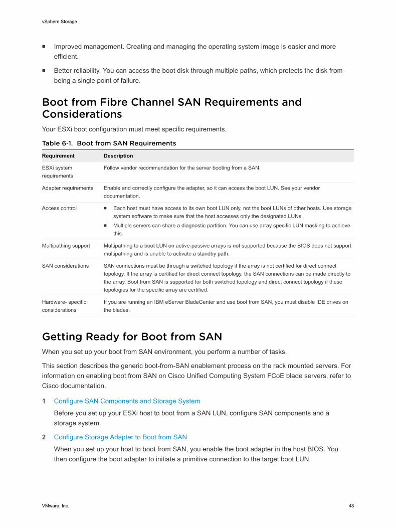
n Improved management. Creating and managing the operating system image is easier and moreefficient.
n Better reliability. You can access the boot disk through multiple paths, which protects the disk frombeing a single point of failure.
Boot from Fibre Channel SAN Requirements andConsiderationsYour ESXi boot configuration must meet specific requirements.
Table 6‑1. Boot from SAN Requirements
Requirement Description
ESXi systemrequirements
Follow vendor recommendation for the server booting from a SAN.
Adapter requirements Enable and correctly configure the adapter, so it can access the boot LUN. See your vendordocumentation.
Access control n Each host must have access to its own boot LUN only, not the boot LUNs of other hosts. Use storagesystem software to make sure that the host accesses only the designated LUNs.
n Multiple servers can share a diagnostic partition. You can use array specific LUN masking to achievethis.
Multipathing support Multipathing to a boot LUN on active-passive arrays is not supported because the BIOS does not supportmultipathing and is unable to activate a standby path.
SAN considerations SAN connections must be through a switched topology if the array is not certified for direct connecttopology. If the array is certified for direct connect topology, the SAN connections can be made directly tothe array. Boot from SAN is supported for both switched topology and direct connect topology if thesetopologies for the specific array are certified.
Hardware- specificconsiderations
If you are running an IBM eServer BladeCenter and use boot from SAN, you must disable IDE drives onthe blades.
Getting Ready for Boot from SANWhen you set up your boot from SAN environment, you perform a number of tasks.
This section describes the generic boot-from-SAN enablement process on the rack mounted servers. Forinformation on enabling boot from SAN on Cisco Unified Computing System FCoE blade servers, refer toCisco documentation.
1 Configure SAN Components and Storage System
Before you set up your ESXi host to boot from a SAN LUN, configure SAN components and astorage system.
2 Configure Storage Adapter to Boot from SAN
When you set up your host to boot from SAN, you enable the boot adapter in the host BIOS. Youthen configure the boot adapter to initiate a primitive connection to the target boot LUN.
vSphere Storage
VMware, Inc. 48
3 Set Up Your System to Boot from Installation Media
When setting up your host to boot from SAN, you first boot the host from the VMware installationmedia. To achieve this, you need to change the system boot sequence in the BIOS setup.
Configure SAN Components and Storage SystemBefore you set up your ESXi host to boot from a SAN LUN, configure SAN components and a storagesystem.
Because configuring the SAN components is vendor specific, refer to the product documentation for eachitem.
Procedure
1 Connect network cable, referring to any cabling guide that applies to your setup.
Check the switch wiring, if there is any.
2 Configure the storage array.
a From the SAN storage array, make the ESXi host visible to the SAN. This process is oftenreferred to as creating an object.
b From the SAN storage array, set up the host to have the WWPNs of the host’s adapters as portnames or node names.
c Create LUNs.
d Assign LUNs.
e Record the IP addresses of the switches and storage arrays.
f Record the WWPN for each SP.
Caution If you use scripted installation to install ESXi in boot from SAN mode, you need to takespecial steps to avoid unintended data loss.
Configure Storage Adapter to Boot from SANWhen you set up your host to boot from SAN, you enable the boot adapter in the host BIOS. You thenconfigure the boot adapter to initiate a primitive connection to the target boot LUN.
Prerequisites
Determine the WWPN for the storage adapter.
Procedure
u Configure the storage adapter to boot from SAN.
Because configuring boot adapters is vendor specific, refer to your vendor documentation.
vSphere Storage
VMware, Inc. 49
Set Up Your System to Boot from Installation MediaWhen setting up your host to boot from SAN, you first boot the host from the VMware installation media.To achieve this, you need to change the system boot sequence in the BIOS setup.
Because changing the boot sequence in the BIOS is vendor specific, refer to vendor documentation forinstructions. The following procedure explains how to change the boot sequence on an IBM host.
Procedure
1 During your system power up, enter the system BIOS Configuration/Setup Utility.
2 Select Startup Options and press Enter.
3 Select Startup Sequence Options and press Enter.
4 Change the First Startup Device to [CD-ROM].
You can now install ESXi.
Configure Emulex HBA to Boot from SANConfiguring the Emulex HBA BIOS to boot from SAN includes enabling the BootBIOS prompt andenabling BIOS.
Procedure
1 Enable the BootBIOS Prompt
When you configure the Emulex HBA BIOS to boot ESXi from SAN, you need to enable theBootBIOS prompt.
2 Enable the BIOS
When you configure the Emulex HBA BIOS to boot ESXi from SAN, you need to enable BIOS.
Enable the BootBIOS PromptWhen you configure the Emulex HBA BIOS to boot ESXi from SAN, you need to enable the BootBIOSprompt.
Procedure
1 Run lputil.
2 Select 3. Firmware Maintenance.
3 Select an adapter.
4 Select 6. Boot BIOS Maintenance.
5 Select 1. Enable Boot BIOS.
vSphere Storage
VMware, Inc. 50
Enable the BIOSWhen you configure the Emulex HBA BIOS to boot ESXi from SAN, you need to enable BIOS.
Procedure
1 Reboot the host.
2 To configure the adapter parameters, press ALT+E at the Emulex prompt and follow these steps.
a Select an adapter (with BIOS support).
b Select 2. Configure This Adapter's Parameters.
c Select 1. Enable or Disable BIOS.
d Select 1 to enable BIOS.
e Select x to exit and Esc to return to the previous menu.
3 To configure the boot device, follow these steps from the Emulex main menu.
a Select the same adapter.
b Select 1. Configure Boot Devices.
c Select the location for the Boot Entry.
d Enter the two-digit boot device.
e Enter the two-digit (HEX) starting LUN (for example, 08).
f Select the boot LUN.
g Select 1. WWPN. (Boot this device using WWPN, not DID).
h Select x to exit and Y to reboot.
4 Boot into the system BIOS and move Emulex first in the boot controller sequence.
5 Reboot and install on a SAN LUN.
Configure QLogic HBA to Boot from SANThis sample procedure explains how to configure the QLogic HBA to boot ESXi from SAN. The procedureinvolves enabling the QLogic HBA BIOS, enabling the selectable boot, and selecting the boot LUN.
Procedure
1 While booting the server, press Ctrl+Q to enter the Fast!UTIL configuration utility.
vSphere Storage
VMware, Inc. 51
2 Perform the appropriate action depending on the number of HBAs.
Option Description
One HBA If you have only one host bus adapter (HBA), the Fast!UTIL Options pageappears. Skip to Step 3.
Multiple HBAs If you have more than one HBA, select the HBA manually.
a In the Select Host Adapter page, use the arrow keys to position the cursor onthe appropriate HBA.
b Press Enter.
3 In the Fast!UTIL Options page, select Configuration Settings and press Enter.
4 In the Configuration Settings page, select Adapter Settings and press Enter.
5 Set the BIOS to search for SCSI devices.
a In the Host Adapter Settings page, select Host Adapter BIOS.
b Press Enter to toggle the value to Enabled.
c Press Esc to exit.
6 Enable the selectable boot.
a Select Selectable Boot Settings and press Enter.
b In the Selectable Boot Settings page, select Selectable Boot.
c Press Enter to toggle the value to Enabled.
7 Use the cursor keys to select the Boot Port Name entry in the list of storage processors (SPs) andpress Enter to open the Select Fibre Channel Device screen.
8 Use the cursor keys to select the specific SP and press Enter.
If you are using an active-passive storage array, the selected SP must be on the preferred (active)path to the boot LUN. If you are not sure which SP is on the active path, use your storage arraymanagement software to find out. The target IDs are created by the BIOS and might change witheach reboot.
9 Perform the appropriate action depending on the number of LUNs attached to the SP.
Option Description
One LUN The LUN is selected as the boot LUN. You do not need to enter the Select LUNscreen.
Multiple LUNs Select LUN screen opens. Use the cursor to select the boot LUN, then pressEnter.
10 If any remaining storage processors show in the list, press C to clear the data.
11 Press Esc twice to exit and press Enter to save the setting.
vSphere Storage
VMware, Inc. 52
Booting ESXi with SoftwareFCoE 7ESXi supports boot from FCoE capable network adapters.
When you install and boot ESXi from an FCoE LUN, the host can use a VMware software FCoE adapterand a network adapter with FCoE capabilities. The host does not require a dedicated FCoE HBA.
You perform most configurations through the option ROM of your network adapter. The network adaptersmust support one of the following formats, which communicate parameters about an FCoE boot device toVMkernel.
n FCoE Boot Firmware Table (FBFT). FBFT is Intel propriety.
n FCoE Boot Parameter Table (FBPT). FBPT is defined by VMware for third-party vendors toimplement software FCoE boot.
The configuration parameters are set in the option ROM of your adapter. During an ESXi installation or asubsequent boot, these parameters are exported in to system memory in either FBFT format or FBPTformat. The VMkernel can read the configuration settings and use them to access the boot LUN.
This chapter includes the following topics:
n Requirements and Considerations for Software FCoE Boot
n Best Practices for Software FCoE Boot
n Set Up Software FCoE Boot
n Troubleshooting Installation and Boot from Software FCoE
Requirements and Considerations for Software FCoEBootWhen you boot the ESXi host from SAN using software FCoE, certain requirements and considerationsapply.
Requirementsn ESXi 5.1 or later.
n The network adapter must have the following capabilities:
n Be FCoE capable.
VMware, Inc. 53
n Support ESXi open FCoE stack.
n Contain FCoE boot firmware which can export boot information in FBFT format or FBPT format.
Considerationsn You cannot change software FCoE boot configuration from within ESXi.
n Coredump is not supported on any software FCoE LUNs, including the boot LUN.
n Multipathing is not supported at pre-boot.
n Boot LUN cannot be shared with other hosts even on shared storage.
Best Practices for Software FCoE BootVMware recommends several best practices when you boot your system from a software FCoE LUN.
n Make sure that the host has access to the entire boot LUN. The boot LUN cannot be shared withother hosts even on shared storage.
n If you use Intel 10 Gigabit Ethernet Controller (Niantec) with a Cisco switch, configure the switch portin the following way:
n Enable the Spanning Tree Protocol (STP).
n Turn off switchport trunk native vlan for the VLAN used for FCoE.
Set Up Software FCoE BootYour ESXi host can boot from a FCoE LUN using the software FCoE adapter a network adapter.
When you configure your host for a software FCoE boot, you perform a number of tasks.
Prerequisites
The network adapter has the following capabilities:
n Support partial FCoE offload (software FCoE).
n Contain either a FCoE Boot Firmware Table (FBFT) or a FCoE Boot Parameter Table (FBPT).
For information about network adapters that support software FCoE boot, see the VMware CompatibilityGuide.
Procedure
1 Configure Software FCoE Boot Parameters
To support a software FCoE boot process, a network adapter on your host must have a speciallyconfigured FCoE boot firmware. When you configure the firmware, you enable the adapter for thesoftware FCoE boot and specify the boot LUN parameters.
2 Install and Boot ESXi from Software FCoE LUN
When you set up your system to boot from a software FCoE LUN, you install the ESXi image to thetarget LUN. You can then boot your host from that LUN.
vSphere Storage
VMware, Inc. 54
Configure Software FCoE Boot ParametersTo support a software FCoE boot process, a network adapter on your host must have a speciallyconfigured FCoE boot firmware. When you configure the firmware, you enable the adapter for thesoftware FCoE boot and specify the boot LUN parameters.
Procedure
u In the option ROM of the network adapter, specify software FCoE boot parameters.
These parameters include boot target, boot LUN, VLAN ID, and so on.
Because configuring the network adapter is vendor specific, review your vendor documentation forinstructions.
Install and Boot ESXi from Software FCoE LUNWhen you set up your system to boot from a software FCoE LUN, you install the ESXi image to the targetLUN. You can then boot your host from that LUN.
Prerequisites
n Configure the option ROM of the network adapter to point to a target LUN that you want to use as theboot LUN. Make sure that you have information about the bootable LUN.
n Change the boot order in the system BIOS to the following sequence:
a The network adapter that you use for the software FCoE boot.
b The ESXi installation media.
See the vendor documentation for your system.
Procedure
1 Start an interactive installation from the ESXi installation CD/DVD.
The ESXi installer verifies that FCoE boot is enabled in the BIOS and, if needed, creates a standardvirtual switch for the FCoE capable network adapter. The name of the vSwitch isVMware_FCoE_vSwitch. The installer then uses preconfigured FCoE boot parameters to discoverand display all available FCoE LUNs.
2 On the Select a Disk screen, select the software FCoE LUN that you specified in the boot parametersetting.
If the boot LUN does not appear in this menu, make sure that you correctly configured bootparameters in the option ROM of the network adapter.
3 Follow the prompts to complete the installation.
4 Reboot the host.
5 Change the boot order in the system BIOS so that the FCoE boot LUN is the first bootable device.
ESXi continues booting from the software FCoE LUN until it is ready to be used.
vSphere Storage
VMware, Inc. 55
What to do next
If needed, you can rename and modify the VMware_FCoE_vSwitch that the installer automaticallycreated. Make sure that the Cisco Discovery Protocol (CDP) mode is set to Listen or Both.
Troubleshooting Installation and Boot from SoftwareFCoEIf the installation or boot of ESXi from a software FCoE LUN fails, you can use several troubleshootingmethods.
Problem
When you install or boot ESXi from FCoE storage using a VMware software FCoE adapter and a networkadapter with partial FCoE offload capabilities, the installation or the boot process fails.
Solution
n Make sure that you correctly configured boot parameters in the option ROM of the FCoE networkadapter.
n During installation, monitor the BIOS of the FCoE network adapter for any errors.
n If possible, check the VMkernel log for errors.
n Use the esxcli command to verify whether the boot LUN is present.
esxcli conn_options hardware bootdevice list
vSphere Storage
VMware, Inc. 56
Best Practices for Fibre ChannelStorage 8When using ESXi with Fibre Channel SAN, follow best practices that VMware offers to avoid performanceproblems.
The vSphere Web Client offer extensive facilities for collecting performance information. The informationis graphically displayed and frequently updated.
You can also use the resxtop or esxtop command-line utilities. The utilities provide a detailed look athow ESXi uses resources in real time. For more information, see the vSphere Resource Managementdocumentation.
Check with your storage representative if your storage system supports Storage API - Array Integrationhardware acceleration features. If it does, refer to your vendor documentation for information on how toenable hardware acceleration support on the storage system side. For more information, see Chapter 23Storage Hardware Acceleration.
This chapter includes the following topics:
n Preventing Fibre Channel SAN Problems
n Disable Automatic Host Registration
n Optimizing Fibre Channel SAN Storage Performance
Preventing Fibre Channel SAN ProblemsWhen using ESXi in conjunction with a Fibre Channel SAN, you must follow specific guidelines to avoidSAN problems.
You should observe these tips for preventing problems with your SAN configuration:
n Place only one VMFS datastore on each LUN.
n Do not change the path policy the system sets for you unless you understand the implications ofmaking such a change.
n Document everything. Include information about zoning, access control, storage, switch, server andFC HBA configuration, software and firmware versions, and storage cable plan.
n Plan for failure:
n Make several copies of your topology maps. For each element, consider what happens to yourSAN if the element fails.
VMware, Inc. 57
n Cross off different links, switches, HBAs and other elements to ensure you did not miss a criticalfailure point in your design.
n Ensure that the Fibre Channel HBAs are installed in the correct slots in the host, based on slot andbus speed. Balance PCI bus load among the available busses in the server.
n Become familiar with the various monitor points in your storage network, at all visibility points,including host's performance charts, FC switch statistics, and storage performance statistics.
n Be cautious when changing IDs of the LUNs that have VMFS datastores being used by your ESXihost. If you change the ID, the datastore becomes inactive and its virtual machines fail. You canresignature the datastore to make it active again. See Managing Duplicate VMFS Datastores.
If there are no running virtual machines on the VMFS datastore, after you change the ID of the LUN,you must use rescan to reset the ID on your host. For information on using rescan, see StorageRefresh and Rescan Operations.
Disable Automatic Host RegistrationCertain storage arrays require that ESXi hosts register with the arrays. ESXi performs automatic hostregistration by sending the host's name and IP address to the array. If you prefer to perform manualregistration using storage management software, disable the ESXi auto-registration feature.
Procedure
1 Browse to the host in the vSphere Web Client navigator.
2 Click the Manage tab, and click Settings.
3 Under System, click Advanced System Settings.
4 Under Advanced System Settings, select the Disk.EnableNaviReg parameter and click the Edit icon.
5 Change the value to 0.
This disables the automatic host registration enabled by default.
Optimizing Fibre Channel SAN Storage PerformanceSeveral factors contribute to optimizing a typical SAN environment.
If the environment is properly configured, the SAN fabric components (particularly the SAN switches) areonly minor contributors because of their low latencies relative to servers and storage arrays. Make surethat the paths through the switch fabric are not saturated, that is, that the switch fabric is running at thehighest throughput.
Storage Array PerformanceStorage array performance is one of the major factors contributing to the performance of the entire SANenvironment.
If there are issues with storage array performance, be sure to consult your storage array vendor’sdocumentation for any relevant information.
vSphere Storage
VMware, Inc. 58
Follow these general guidelines to improve the array performance in the vSphere environment:
n When assigning LUNs, remember that each LUN is accessed by a number of hosts, and that anumber of virtual machines can run on each host. One LUN used by a host can service I/O frommany different applications running on different operating systems. Because of this diverse workload,the RAID group containing the ESXi LUNs should not include LUNs used by other servers that arenot running ESXi.
n Make sure read/write caching is enabled.
n SAN storage arrays require continual redesign and tuning to ensure that I/O is load balanced acrossall storage array paths. To meet this requirement, distribute the paths to the LUNs among all the SPsto provide optimal load balancing. Close monitoring indicates when it is necessary to rebalance theLUN distribution.
Tuning statically balanced storage arrays is a matter of monitoring the specific performance statistics(such as I/O operations per second, blocks per second, and response time) and distributing the LUNworkload to spread the workload across all the SPs.
Note Dynamic load balancing is not currently supported with ESXi.
Server Performance with Fibre ChannelYou must consider several factors to ensure optimal server performance.
Each server application must have access to its designated storage with the following conditions:
n High I/O rate (number of I/O operations per second)
n High throughput (megabytes per second)
n Minimal latency (response times)
Because each application has different requirements, you can meet these goals by choosing anappropriate RAID group on the storage array. To achieve performance goals:
n Place each LUN on a RAID group that provides the necessary performance levels. Pay attention tothe activities and resource utilization of other LUNS in the assigned RAID group. A high-performanceRAID group that has too many applications doing I/O to it might not meet performance goals requiredby an application running on the ESXi host.
n Make sure that each server has a sufficient number of HBAs to allow maximum throughput for all theapplications hosted on the server for the peak period. I/O spread across multiple HBAs provide higherthroughput and less latency for each application.
n To provide redundancy in the event of HBA failure, make sure the server is connected to a dualredundant fabric.
vSphere Storage
VMware, Inc. 59
n When allocating LUNs or RAID groups for ESXi systems, multiple operating systems use and sharethat resource. As a result, the performance required from each LUN in the storage subsystem can bemuch higher if you are working with ESXi systems than if you are using physical machines. Forexample, if you expect to run four I/O intensive applications, allocate four times the performancecapacity for the ESXi LUNs.
n When using multiple ESXi systems in conjunction with vCenter Server, the performance needed fromthe storage subsystem increases correspondingly.
n The number of outstanding I/Os needed by applications running on an ESXi system should match thenumber of I/Os the HBA and storage array can handle.
vSphere Storage
VMware, Inc. 60
Using ESXi with iSCSI SAN 9You can use ESXi in conjunction with a storage area network (SAN), a specialized high-speed networkthat connects computer systems to high-performance storage subsystems. Using ESXi together with aSAN provides storage consolidation, improves reliability, and helps with disaster recovery.
To use ESXi effectively with a SAN, you must have a working knowledge of ESXi systems and SANconcepts. Also, when you set up ESXi hosts to use Internet SCSI (iSCSI) SAN storage systems, you mustbe aware of certain special considerations that exist.
This chapter includes the following topics:
n iSCSI SAN Concepts
n How Virtual Machines Access Data on an iSCSI SAN
iSCSI SAN ConceptsIf you are an administrator who plans to set up ESXi hosts to work with iSCSI SANs, you must have aworking knowledge of iSCSI concepts.
iSCSI SANs use Ethernet connections between computer systems, or host servers, and highperformance storage subsystems. The SAN components include iSCSI host bus adapters (HBAs) orNetwork Interface Cards (NICs) in the host servers, switches and routers that transport the storage traffic,cables, storage processors (SPs), and storage disk systems.
iSCSI SAN uses a client-server architecture. The client, called iSCSI initiator, operates on your host. Itinitiates iSCSI sessions by issuing SCSI commands and transmitting them, encapsulated into iSCSIprotocol, to a server. The server is known as an iSCSI target. The iSCSI target represents a physicalstorage system on the network. It can also be provided by a virtual iSCSI SAN, for example, an iSCSItarget emulator running in a virtual machine. The iSCSI target responds to the initiator's commands bytransmitting required iSCSI data.
iSCSI MultipathingWhen transferring data between the host server and storage, the SAN uses a technique known asmultipathing. Multipathing allows you to have more than one physical path from the ESXi host to a LUNon a storage system.
VMware, Inc. 61
Generally, a single path from a host to a LUN consists of an iSCSI adapter or NIC, switch ports,connecting cables, and the storage controller port. If any component of the path fails, the host selectsanother available path for I/O. The process of detecting a failed path and switching to another is calledpath failover.
For more information on multipathing, see Chapter 17 Understanding Multipathing and Failover.
Ports in the iSCSI SANA single discoverable entity on the iSCSI SAN, such as an initiator or a target, represents an iSCSI node.Each node has one or more ports that connect it to the SAN.
iSCSI ports are end-points of an iSCSI session. Each node can be identified in a number of ways.
IP Address Each iSCSI node can have an IP address associated with it so that routingand switching equipment on your network can establish the connectionbetween the server and storage. This address is just like the IP addressthat you assign to your computer to get access to your company's networkor the Internet.
iSCSI Name A worldwide unique name for identifying the node. iSCSI uses the iSCSIQualified Name (IQN) and Extended Unique Identifier (EUI).
By default, ESXi generates unique iSCSI names for your iSCSI initiators,for example, iqn.1998-01.com.vmware:iscsitestox-68158ef2.Usually, you do not have to change the default value, but if you do, makesure that the new iSCSI name you enter is worldwide unique.
iSCSI Alias A more manageable name for an iSCSI device or port used instead of theiSCSI name. iSCSI aliases are not unique and are intended to be just afriendly name to associate with a port.
iSCSI Naming ConventionsiSCSI uses a special unique name to identify an iSCSI node, either target or initiator. This name is similarto the WorldWide Name (WWN) associated with Fibre Channel devices and is used as a way touniversally identify the node.
iSCSI names are formatted in two different ways. The most common is the IQN format.
For more details on iSCSI naming requirements and string profiles, see RFC 3721 and RFC 3722 on theIETF Web site.
iSCSI Qualified Name (IQN) FormatThe IQN format takes the form iqn.yyyy-mm.naming-authority:unique name, where:
n yyyy-mm is the year and month when the naming authority was established.
vSphere Storage
VMware, Inc. 62
n naming-authority is usually reverse syntax of the Internet domain name of the naming authority. Forexample, the iscsi.vmware.com naming authority could have the iSCSI qualified name form of iqn.1998-01.com.vmware.iscsi. The name indicates that the vmware.com domain name was registered inJanuary of 1998, and iscsi is a subdomain, maintained by vmware.com.
n unique name is any name you want to use, for example, the name of your host. The naming authoritymust make sure that any names assigned following the colon are unique, such as:n iqn.1998-01.com.vmware.iscsi:name1
n iqn.1998-01.com.vmware.iscsi:name2
n iqn.1998-01.com.vmware.iscsi:name999
Enterprise Unique Identifier (EUI) FormatThe EUI format takes the form eui.16 hex digits.
For example, eui.0123456789ABCDEF.
The 16-hexadecimal digits are text representations of a 64-bit number of an IEEE EUI (extended uniqueidentifier) format. The top 24 bits are a company ID that IEEE registers with a particular company. Thelower 40 bits are assigned by the entity holding that company ID and must be unique.
iSCSI InitiatorsTo access iSCSI targets, your host uses iSCSI initiators. The initiators transport SCSI requests andresponses, encapsulated into the iSCSI protocol, between the host and the iSCSI target.
Your host supports different types of initiators.
For information on configuring and using iSCSI adapters, see Chapter 10 Configuring iSCSI Adapters andStorage.
Software iSCSI AdapterA software iSCSI adapter is a VMware code built into the VMkernel. It allows your host to connect to theiSCSI storage device through standard network adapters. The software iSCSI adapter handles iSCSIprocessing while communicating with the network adapter. With the software iSCSI adapter, you can useiSCSI technology without purchasing specialized hardware.
Hardware iSCSI AdapterA hardware iSCSI adapter is a third-party adapter that offloads iSCSI and network processing from yourhost. Hardware iSCSI adapters are divided into categories.
Dependent HardwareiSCSI Adapter
Depends on VMware networking, and iSCSI configuration andmanagement interfaces provided by VMware.
vSphere Storage
VMware, Inc. 63
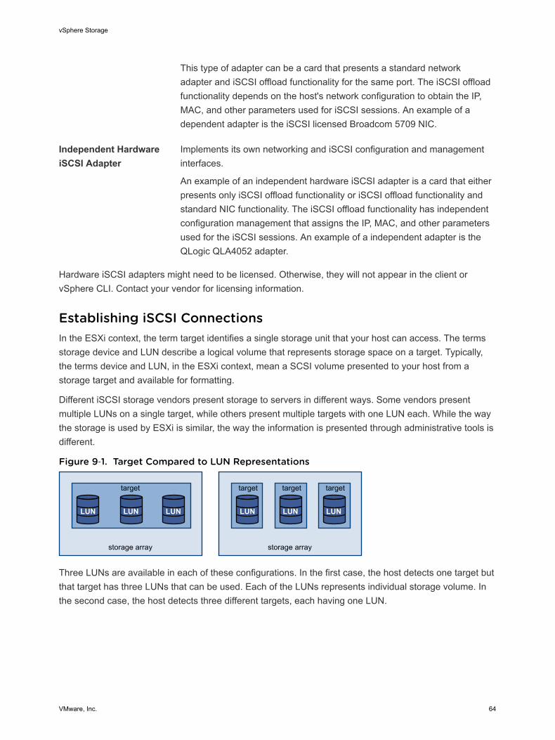
This type of adapter can be a card that presents a standard networkadapter and iSCSI offload functionality for the same port. The iSCSI offloadfunctionality depends on the host's network configuration to obtain the IP,MAC, and other parameters used for iSCSI sessions. An example of adependent adapter is the iSCSI licensed Broadcom 5709 NIC.
Independent HardwareiSCSI Adapter
Implements its own networking and iSCSI configuration and managementinterfaces.
An example of an independent hardware iSCSI adapter is a card that eitherpresents only iSCSI offload functionality or iSCSI offload functionality andstandard NIC functionality. The iSCSI offload functionality has independentconfiguration management that assigns the IP, MAC, and other parametersused for the iSCSI sessions. An example of a independent adapter is theQLogic QLA4052 adapter.
Hardware iSCSI adapters might need to be licensed. Otherwise, they will not appear in the client orvSphere CLI. Contact your vendor for licensing information.
Establishing iSCSI ConnectionsIn the ESXi context, the term target identifies a single storage unit that your host can access. The termsstorage device and LUN describe a logical volume that represents storage space on a target. Typically,the terms device and LUN, in the ESXi context, mean a SCSI volume presented to your host from astorage target and available for formatting.
Different iSCSI storage vendors present storage to servers in different ways. Some vendors presentmultiple LUNs on a single target, while others present multiple targets with one LUN each. While the waythe storage is used by ESXi is similar, the way the information is presented through administrative tools isdifferent.
Figure 9‑1. Target Compared to LUN Representations
storage array
target
LUN LUN LUN
storage array
target target target
LUN LUN LUN
Three LUNs are available in each of these configurations. In the first case, the host detects one target butthat target has three LUNs that can be used. Each of the LUNs represents individual storage volume. Inthe second case, the host detects three different targets, each having one LUN.
vSphere Storage
VMware, Inc. 64
Host-based iSCSI initiators establish connections to each target. Storage systems with a single targetcontaining multiple LUNs have traffic to all the LUNs on a single connection. With a system that has threetargets with one LUN each, a host uses separate connections to the three LUNs. This information isuseful when you are trying to aggregate storage traffic on multiple connections from the host with multipleiSCSI HBAs, where traffic for one target can be set to a particular HBA, while traffic for another target canuse a different HBA.
iSCSI Storage System TypesESXi supports different storage systems and arrays.
The types of storage that your host supports include active-active, active-passive, and ALUA-compliant.
Active-active storagesystem
Allows access to the LUNs simultaneously through all the storage ports thatare available without significant performance degradation. All the paths areactive at all times, unless a path fails.
Active-passive storagesystem
A system in which one storage processor is actively providing access to agiven LUN. The other processors act as backup for the LUN and can beactively providing access to other LUN I/O. I/O can be successfully sentonly to an active port for a given LUN. If access through the active storageport fails, one of the passive storage processors can be activated by theservers accessing it.
Asymmetrical storagesystem
Supports Asymmetric Logical Unit Access (ALUA). ALUA-complaint storagesystems provide different levels of access per port. ALUA allows hosts todetermine the states of target ports and prioritize paths. The host usessome of the active paths as primary while others as secondary.
Virtual port storagesystem
Allows access to all available LUNs through a single virtual port. These areactive-active storage devices, but hide their multiple connections though asingle port. ESXi multipathing does not make multiple connections from aspecific port to the storage by default. Some storage vendors supplysession managers to establish and manage multiple connections to theirstorage. These storage systems handle port failover and connectionbalancing transparently. This is often referred to as transparent failover.
Discovery, Authentication, and Access ControlYou can use several mechanisms to discover your storage and to limit access to it.
You must configure your host and the iSCSI storage system to support your storage access control policy.
DiscoveryA discovery session is part of the iSCSI protocol, and it returns the set of targets you can access on aniSCSI storage system. The two types of discovery available on ESXi are dynamic and static. Dynamicdiscovery obtains a list of accessible targets from the iSCSI storage system, while static discovery canonly try to access one particular target by target name and address.
vSphere Storage
VMware, Inc. 65
For more information, see Configuring Discovery Addresses for iSCSI Adapters.
AuthenticationiSCSI storage systems authenticate an initiator by a name and key pair. ESXi supports the CHAPprotocol, which VMware recommends for your SAN implementation. To use CHAP authentication, theESXi host and the iSCSI storage system must have CHAP enabled and have common credentials.
For information on enabling CHAP, see Configuring CHAP Parameters for iSCSI Adapters.
Access ControlAccess control is a policy set up on the iSCSI storage system. Most implementations support one or moreof three types of access control:
n By initiator name
n By IP address
n By the CHAP protocol
Only initiators that meet all rules can access the iSCSI volume.
Using only CHAP for access control can slow down rescans because the ESXi host can discover alltargets, but then fails at the authentication step. iSCSI rescans work faster if the host discovers only thetargets it can authenticate.
Error CorrectionTo protect the integrity of iSCSI headers and data, the iSCSI protocol defines error correction methodsknown as header digests and data digests.
Both parameters are disabled by default, but you can enable them. These digests pertain to, respectively,the header and SCSI data being transferred between iSCSI initiators and targets, in both directions.
Header and data digests check the end-to-end, noncryptographic data integrity beyond the integritychecks that other networking layers provide, such as TCP and Ethernet. They check the entirecommunication path, including all elements that can change the network-level traffic, such as routers,switches, and proxies.
The existence and type of the digests are negotiated when an iSCSI connection is established. When theinitiator and target agree on a digest configuration, this digest must be used for all traffic between them.
Enabling header and data digests does require additional processing for both the initiator and the targetand can affect throughput and CPU use performance.
Note Systems that use Intel Nehalem processors offload the iSCSI digest calculations, thus reducing theimpact on performance.
For information on enabling header and data digests, see Configuring Advanced Parameters for iSCSI.
vSphere Storage
VMware, Inc. 66
How Virtual Machines Access Data on an iSCSI SANESXi stores a virtual machine's disk files within a VMFS datastore that resides on a SAN storage device.When virtual machine guest operating systems issue SCSI commands to their virtual disks, the SCSIvirtualization layer translates these commands to VMFS file operations.
When a virtual machine interacts with its virtual disk stored on a SAN, the following process takes place:
1 When the guest operating system in a virtual machine reads or writes to SCSI disk, it issues SCSIcommands to the virtual disk.
2 Device drivers in the virtual machine’s operating system communicate with the virtual SCSIcontrollers.
3 The virtual SCSI controller forwards the command to the VMkernel.
4 The VMkernel performs the following tasks.
a Locates the file, which corresponds to the guest virtual machine disk, in the VMFS volume.
b Maps the requests for the blocks on the virtual disk to blocks on the appropriate physical device.
c Sends the modified I/O request from the device driver in the VMkernel to the iSCSI initiator(hardware or software).
5 If the iSCSI initiator is a hardware iSCSI adapter (both independent or dependent), the adapterperforms the following tasks.
a Encapsulates I/O requests into iSCSI Protocol Data Units (PDUs).
b Encapsulates iSCSI PDUs into TCP/IP packets.
c Sends IP packets over Ethernet to the iSCSI storage system.
6 If the iSCSI initiator is a software iSCSI adapter, the following takes place.
a The iSCSI initiator encapsulates I/O requests into iSCSI PDUs.
b The initiator sends iSCSI PDUs through TCP/IP connections.
c The VMkernel TCP/IP stack relays TCP/IP packets to a physical NIC.
d The physical NIC sends IP packets over Ethernet to the iSCSI storage system.
7 Depending on which port the iSCSI initiator uses to connect to the network, Ethernet switches androuters carry the request to the storage device that the host wants to access.
vSphere Storage
VMware, Inc. 67
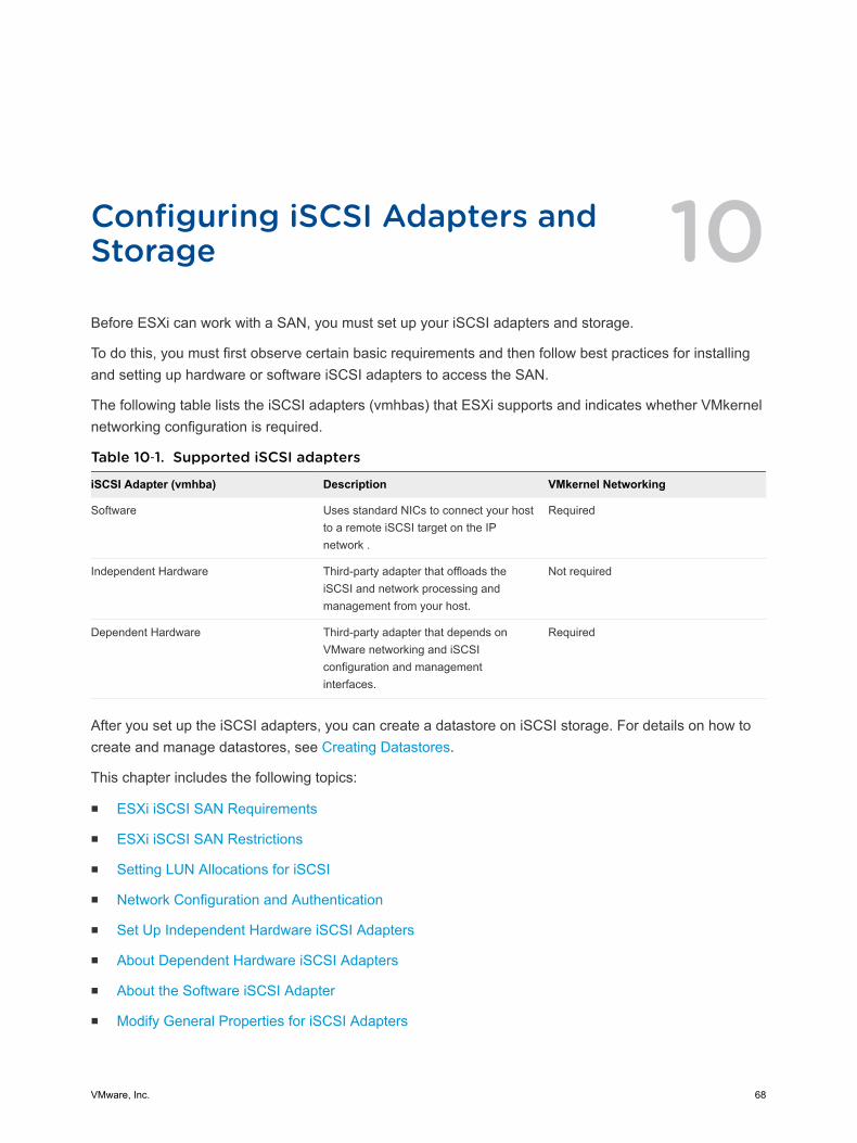
Configuring iSCSI Adapters andStorage 10Before ESXi can work with a SAN, you must set up your iSCSI adapters and storage.
To do this, you must first observe certain basic requirements and then follow best practices for installingand setting up hardware or software iSCSI adapters to access the SAN.
The following table lists the iSCSI adapters (vmhbas) that ESXi supports and indicates whether VMkernelnetworking configuration is required.
Table 10‑1. Supported iSCSI adapters
iSCSI Adapter (vmhba) Description VMkernel Networking
Software Uses standard NICs to connect your hostto a remote iSCSI target on the IPnetwork .
Required
Independent Hardware Third-party adapter that offloads theiSCSI and network processing andmanagement from your host.
Not required
Dependent Hardware Third-party adapter that depends onVMware networking and iSCSIconfiguration and managementinterfaces.
Required
After you set up the iSCSI adapters, you can create a datastore on iSCSI storage. For details on how tocreate and manage datastores, see Creating Datastores.
This chapter includes the following topics:
n ESXi iSCSI SAN Requirements
n ESXi iSCSI SAN Restrictions
n Setting LUN Allocations for iSCSI
n Network Configuration and Authentication
n Set Up Independent Hardware iSCSI Adapters
n About Dependent Hardware iSCSI Adapters
n About the Software iSCSI Adapter
n Modify General Properties for iSCSI Adapters
VMware, Inc. 68
n Setting Up iSCSI Network
n Using Jumbo Frames with iSCSI
n Configuring Discovery Addresses for iSCSI Adapters
n Configuring CHAP Parameters for iSCSI Adapters
n Configuring Advanced Parameters for iSCSI
n iSCSI Session Management
ESXi iSCSI SAN RequirementsYou must meet several requirements for your ESXi host to work properly with a SAN.
n Verify that your SAN storage hardware and firmware combinations are supported in conjunction withESXi systems. For an up-to-date list, see VMware Compatibility Guide.
n Configure your system to have only one VMFS datastore for each LUN.
n Unless you are using diskless servers, set up a diagnostic partition on a local storage. If you havediskless servers that boot from iSCSI SAN, see General Boot from iSCSI SAN Recommendations forinformation about diagnostic partitions with iSCSI.
n Use RDMs for access to any raw disk. For information, see Chapter 18 Raw Device Mapping.
n Set the SCSI controller driver in the guest operating system to a large enough queue. For informationon changing queue depth for iSCSI adapters and virtual machines, see vSphere Troubleshooting.
n On virtual machines running Microsoft Windows, increase the value of the SCSI TimeoutValueparameter to allow Windows to better tolerate delayed I/O resulting from path failover. Forinformation, see Set Timeout on Windows Guest OS.
ESXi iSCSI SAN RestrictionsA number of restrictions exist when you use ESXi with an iSCSI SAN.
n ESXi does not support iSCSI-connected tape devices.
n You cannot use virtual-machine multipathing software to perform I/O load balancing to a singlephysical LUN.
n ESXi does not support multipathing when you combine independent hardware adapters with eithersoftware or dependent hardware adapters.
Setting LUN Allocations for iSCSIWhen preparing your ESXi system to use iSCSI SAN storage you need to set LUN allocations.
vSphere Storage
VMware, Inc. 69
Note the following points:
n Storage Provisioning. To ensure that the host recognizes LUNs at startup time, configure all iSCSIstorage targets so that your host can access them and use them. Also, configure your host so that itcan discover all available iSCSI targets.
n vMotion and VMware DRS. When you use vCenter Server and vMotion or DRS, make sure that theLUNs for the virtual machines are provisioned to all hosts. This configuration provides the greatestfreedom in moving virtual machines.
n Active-active versus active-passive arrays. When you use vMotion or DRS with an active-passiveSAN storage device, make sure that all hosts have consistent paths to all storage processors. Notdoing so can cause path thrashing when a vMotion migration occurs.
For active-passive storage arrays not listed in Storage/SAN Compatibility, VMware does not supportstorage-port failover. You must connect the server to the active port on the storage system. Thisconfiguration ensures that the LUNs are presented to the host.
Network Configuration and AuthenticationBefore your ESXi host can discover iSCSI storage, the iSCSI initiators must be configured andauthentication might have to be set up.
n For software iSCSI and dependent hardware iSCSI, networking for the VMkernel must be configured.You can verify the network configuration by using the vmkping utility. With software iSCSI anddependent iSCSI, IPv4 and IPv6 protocols are supported.
n For independent hardware iSCSI, network parameters, such as IP address, subnet mask, and defaultgateway must be configured on the HBA. You can also specify a network protocol, IPv4 or IPv6 forthe adapter.
n Check and change the default initiator name if necessary.
n The dynamic discovery address or static discovery address and target name of the storage systemmust be set. For software iSCSI and dependent hardware iSCSI, the address should be pingableusing vmkping.
n For CHAP authentication, enable it on the initiator and the storage system side. After authentication isenabled, it applies for all of the targets that are not yet discovered, but does not apply to targets thatare already discovered. After the discovery address is set, the new targets discovered are exposedand can be used at that point.
For details on how to use the vmkping command, search the VMware Knowledge Base.
Set Up Independent Hardware iSCSI AdaptersAn independent hardware iSCSI adapter is a specialized third-party adapter capable of accessing iSCSIstorage over TCP/IP. This iSCSI adapter handles all iSCSI and network processing and management foryour ESXi system.
vSphere Storage
VMware, Inc. 70
Prerequisites
n Check whether the adapter needs to be licensed.
n Install the adapter.
For information about licencing, installation, and firmware updates, see vendor documentation.
Procedure
1 View Independent Hardware iSCSI Adapters
View an independent hardware iSCSI adapter to verify that it is correctly installed and ready forconfiguration.
2 Modify General Properties for iSCSI Adapters
You can change the default iSCSI name and alias assigned to your iSCSI adapters. For the forindependent hardware iSCSI adapters, you can also change the default IP settings.
3 Edit Network Settings for Hardware iSCSI
After you install an independent hardware iSCSI adapter, you might need to change its defaultnetwork settings so that the adapter is configured properly for the iSCSI SAN.
4 Set Up Dynamic or Static Discovery for iSCSI
With dynamic discovery, each time the initiator contacts a specified iSCSI storage system, it sendsthe SendTargets request to the system. The iSCSI system responds by supplying a list of availabletargets to the initiator. In addition to the dynamic discovery method, you can use static discovery andmanually enter information for the targets.
What to do next
If required, configure CHAP parameters and jumbo frames.
View Independent Hardware iSCSI AdaptersView an independent hardware iSCSI adapter to verify that it is correctly installed and ready forconfiguration.
After you install an independent hardware iSCSI adapter on a host, it appears on the list of storageadapters available for configuration. You can view its properties.
Prerequisites
Required privilege: Host.Configuration.Storage Partition Configuration
Procedure
1 Browse to the host in the vSphere Web Client navigator.
2 Click the Manage tab, and click Storage.
3 Click Storage Adapters.
If installed, the hardware iSCSI adapter appears on the list of storage adapters.
vSphere Storage
VMware, Inc. 71
4 Select the adapter to view.
The default details for the adapter appear, including the model, iSCSI name, iSCSI alias, IP address,and target and paths information.
Modify General Properties for iSCSI AdaptersYou can change the default iSCSI name and alias assigned to your iSCSI adapters. For the forindependent hardware iSCSI adapters, you can also change the default IP settings.
Important When you modify any default properties for your iSCSI adapters, make sure to correctlyformat their names and IP addresses.
Prerequisites
Required privilege: Host .Configuration.Storage Partition Configuration
Procedure
1 Browse to the host in the vSphere Web Client navigator.
2 Click the Manage tab, and click Storage.
3 Click Storage Adapters, and select the adapter (vmhba#) to configure.
4 Under Adapter Details, click the Properties tab and click Edit in the General panel.
5 To change the default iSCSI name for your adapter, enter the new name.
Make sure the name you enter is worldwide unique and properly formatted or some storage devicesmight not recognize the iSCSI adapter.
6 (Optional) Enter the iSCSI alias.
The alias is a name that you use to identify the iSCSI adapter.
If you change the iSCSI name, it will be used for new iSCSI sessions. For existing sessions, new settingswill not be used until logout and re-login.
Edit Network Settings for Hardware iSCSIAfter you install an independent hardware iSCSI adapter, you might need to change its default networksettings so that the adapter is configured properly for the iSCSI SAN.
Procedure
1 Browse to the host in the vSphere Web Client navigator.
2 Click the Manage tab, and click Storage.
3 Click Storage Adapters, and select the adapter (vmhba#) to configure.
4 Under Adapter Details, click the Network Settings tab and click Edit.
vSphere Storage
VMware, Inc. 72
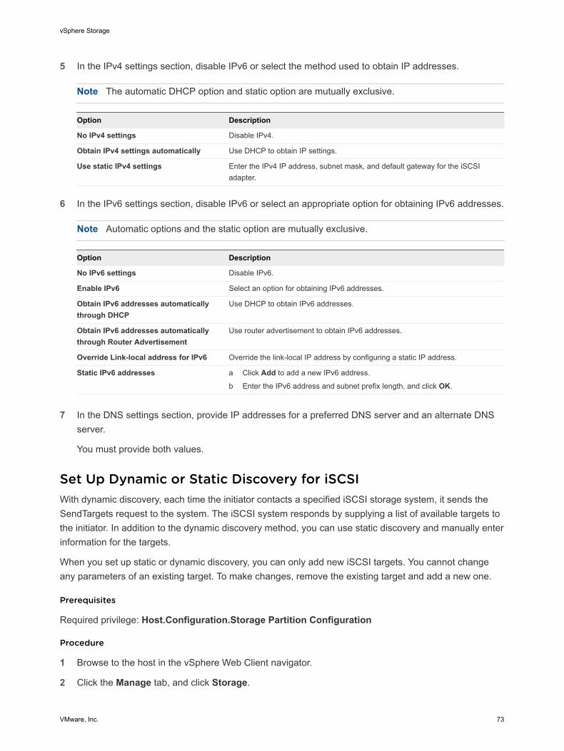
5 In the IPv4 settings section, disable IPv6 or select the method used to obtain IP addresses.
Note The automatic DHCP option and static option are mutually exclusive.
Option Description
No IPv4 settings Disable IPv4.
Obtain IPv4 settings automatically Use DHCP to obtain IP settings.
Use static IPv4 settings Enter the IPv4 IP address, subnet mask, and default gateway for the iSCSIadapter.
6 In the IPv6 settings section, disable IPv6 or select an appropriate option for obtaining IPv6 addresses.
Note Automatic options and the static option are mutually exclusive.
Option Description
No IPv6 settings Disable IPv6.
Enable IPv6 Select an option for obtaining IPv6 addresses.
Obtain IPv6 addresses automaticallythrough DHCP
Use DHCP to obtain IPv6 addresses.
Obtain IPv6 addresses automaticallythrough Router Advertisement
Use router advertisement to obtain IPv6 addresses.
Override Link-local address for IPv6 Override the link-local IP address by configuring a static IP address.
Static IPv6 addresses a Click Add to add a new IPv6 address.
b Enter the IPv6 address and subnet prefix length, and click OK.
7 In the DNS settings section, provide IP addresses for a preferred DNS server and an alternate DNSserver.
You must provide both values.
Set Up Dynamic or Static Discovery for iSCSIWith dynamic discovery, each time the initiator contacts a specified iSCSI storage system, it sends theSendTargets request to the system. The iSCSI system responds by supplying a list of available targets tothe initiator. In addition to the dynamic discovery method, you can use static discovery and manually enterinformation for the targets.
When you set up static or dynamic discovery, you can only add new iSCSI targets. You cannot changeany parameters of an existing target. To make changes, remove the existing target and add a new one.
Prerequisites
Required privilege: Host.Configuration.Storage Partition Configuration
Procedure
1 Browse to the host in the vSphere Web Client navigator.
2 Click the Manage tab, and click Storage.
vSphere Storage
VMware, Inc. 73
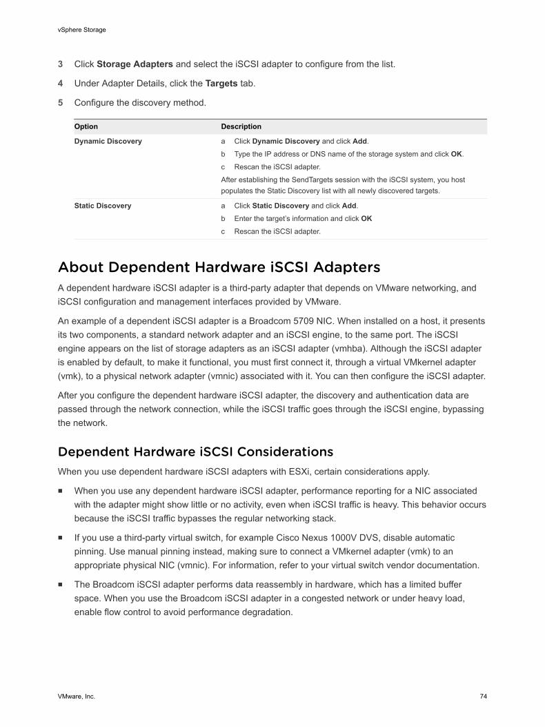
3 Click Storage Adapters and select the iSCSI adapter to configure from the list.
4 Under Adapter Details, click the Targets tab.
5 Configure the discovery method.
Option Description
Dynamic Discovery a Click Dynamic Discovery and click Add.
b Type the IP address or DNS name of the storage system and click OK.
c Rescan the iSCSI adapter.
After establishing the SendTargets session with the iSCSI system, you hostpopulates the Static Discovery list with all newly discovered targets.
Static Discovery a Click Static Discovery and click Add.
b Enter the target’s information and click OKc Rescan the iSCSI adapter.
About Dependent Hardware iSCSI AdaptersA dependent hardware iSCSI adapter is a third-party adapter that depends on VMware networking, andiSCSI configuration and management interfaces provided by VMware.
An example of a dependent iSCSI adapter is a Broadcom 5709 NIC. When installed on a host, it presentsits two components, a standard network adapter and an iSCSI engine, to the same port. The iSCSIengine appears on the list of storage adapters as an iSCSI adapter (vmhba). Although the iSCSI adapteris enabled by default, to make it functional, you must first connect it, through a virtual VMkernel adapter(vmk), to a physical network adapter (vmnic) associated with it. You can then configure the iSCSI adapter.
After you configure the dependent hardware iSCSI adapter, the discovery and authentication data arepassed through the network connection, while the iSCSI traffic goes through the iSCSI engine, bypassingthe network.
Dependent Hardware iSCSI ConsiderationsWhen you use dependent hardware iSCSI adapters with ESXi, certain considerations apply.
n When you use any dependent hardware iSCSI adapter, performance reporting for a NIC associatedwith the adapter might show little or no activity, even when iSCSI traffic is heavy. This behavior occursbecause the iSCSI traffic bypasses the regular networking stack.
n If you use a third-party virtual switch, for example Cisco Nexus 1000V DVS, disable automaticpinning. Use manual pinning instead, making sure to connect a VMkernel adapter (vmk) to anappropriate physical NIC (vmnic). For information, refer to your virtual switch vendor documentation.
n The Broadcom iSCSI adapter performs data reassembly in hardware, which has a limited bufferspace. When you use the Broadcom iSCSI adapter in a congested network or under heavy load,enable flow control to avoid performance degradation.
vSphere Storage
VMware, Inc. 74
Flow control manages the rate of data transmission between two nodes to prevent a fast sender fromoverrunning a slow receiver. For best results, enable flow control at the end points of the I/O path, atthe hosts and iSCSI storage systems.
To enable flow control for the host, use the esxcli system module parameters command. Fordetails, see the VMware knowledge base article at http://kb.vmware.com/kb/1013413
n Dependent hardware adapters support IPv4 and IPv6.
Configure Dependent Hardware iSCSI AdaptersThe entire setup and configuration process for the dependent hardware iSCSI adapters involves severalsteps. After you set up your adapter, you might need to configure CHAP parameters and Jumbo Frames.
Procedure
1 View Dependent Hardware iSCSI Adapters
View a dependent hardware iSCSI adapter to verify that it is correctly loaded.
2 Modify General Properties for iSCSI Adapters
You can change the default iSCSI name and alias assigned to your iSCSI adapters. For the forindependent hardware iSCSI adapters, you can also change the default IP settings.
3 Determine Association Between iSCSI and Network Adapters
You create network connections to bind dependent iSCSI and physical network adapters. To createthe connections correctly, you must determine the name of the physical NIC with which thedependent hardware iSCSI adapter is associated.
4 Create Network Connections for iSCSI
Configure connections for the traffic between the software or dependent hardware iSCSI adaptersand the physical network adapters.
5 Set Up Dynamic or Static Discovery for iSCSI
With dynamic discovery, each time the initiator contacts a specified iSCSI storage system, it sendsthe SendTargets request to the system. The iSCSI system responds by supplying a list of availabletargets to the initiator. In addition to the dynamic discovery method, you can use static discovery andmanually enter information for the targets.
What to do next
If required, configure CHAP parameters and jumbo frames.
View Dependent Hardware iSCSI AdaptersView a dependent hardware iSCSI adapter to verify that it is correctly loaded.
If installed, the dependent hardware iSCSI adapter (vmhba#) appears on the list of storage adaptersunder such category as, for example, Broadcom iSCSI Adapter. If the dependent hardware adapter doesnot appear on the list of storage adapters, check whether it needs to be licensed. See your vendordocumentation.
vSphere Storage
VMware, Inc. 75
Procedure
1 Browse to the host in the vSphere Web Client navigator.
2 Click the Manage tab, and click Storage.
3 Click Storage Adapters.
4 Select the adapter (vmhba#) to view.
The default details for the adapter appear, including the iSCSI name, iSCSI alias, and the status.
What to do next
Although the dependent iSCSI adapter is enabled by default, to make it functional, you must set upnetworking for the iSCSI traffic and bind the adapter to the appropriate VMkernel iSCSI port. You thenconfigure discovery addresses and CHAP parameters.
Modify General Properties for iSCSI AdaptersYou can change the default iSCSI name and alias assigned to your iSCSI adapters. For the forindependent hardware iSCSI adapters, you can also change the default IP settings.
Important When you modify any default properties for your iSCSI adapters, make sure to correctlyformat their names and IP addresses.
Prerequisites
Required privilege: Host .Configuration.Storage Partition Configuration
Procedure
1 Browse to the host in the vSphere Web Client navigator.
2 Click the Manage tab, and click Storage.
3 Click Storage Adapters, and select the adapter (vmhba#) to configure.
4 Under Adapter Details, click the Properties tab and click Edit in the General panel.
5 To change the default iSCSI name for your adapter, enter the new name.
Make sure the name you enter is worldwide unique and properly formatted or some storage devicesmight not recognize the iSCSI adapter.
6 (Optional) Enter the iSCSI alias.
The alias is a name that you use to identify the iSCSI adapter.
If you change the iSCSI name, it will be used for new iSCSI sessions. For existing sessions, new settingswill not be used until logout and re-login.
vSphere Storage
VMware, Inc. 76
Determine Association Between iSCSI and Network AdaptersYou create network connections to bind dependent iSCSI and physical network adapters. To create theconnections correctly, you must determine the name of the physical NIC with which the dependenthardware iSCSI adapter is associated.
Prerequisites
In the vSphere Web Client, browse to the dependent hardware iSCSI adapter (vmhba#). See ViewDependent Hardware iSCSI Adapters.
Procedure
1 Select the iSCSI adapter (vmhba#) and click the Network Port Binding tab under Adapter Details.
2 Click Add.
The network adapter (vmnic#) that corresponds to the dependent iSCSI adapter is listed in thePhysical Network Adapter column.
What to do next
If the VMkernel Adapter column is empty, create a VMkernel adapter (vmk#) for the physical networkadapter (vmnic#) and then bind them to the associated dependent hardware iSCSI. See Setting Up iSCSINetwork.
Create Network Connections for iSCSIConfigure connections for the traffic between the software or dependent hardware iSCSI adapters and thephysical network adapters.
The following tasks discuss the iSCSI network configuration with a vSphere standard switch.
If you use a vSphere distributed switch with multiple uplink ports, for port binding, create a separatedistributed port group per each physical NIC. Then set the team policy so that each distributed port grouphas only one active uplink port. For detailed information on vSphere distributed switches, see the vSphereNetworking documentation.
Procedure
1 Create a Single VMkernel Adapter for iSCSI
Connect the VMkernel, which runs services for iSCSI storage, to a physical network adapter.
2 Create Additional VMkernel Adapters for iSCSI
Use this task if you have two or more physical network adapters for iSCSI and you want to connectall of your physical adapters to a single vSphere standard switch. In this task, you add the physicaladapters and VMkernel adapters to an existing vSphere standard switch.
3 Change Network Policy for iSCSI
If you use a single vSphere standard switch to connect multiple VMkernel adapters to multiplenetwork adapters, set up network policy so that only one physical network adapter is active for eachVMkernel adapter.
vSphere Storage
VMware, Inc. 77
4 Bind iSCSI and VMkernel Adapters
Bind an iSCSI adapter with a VMkernel adapter.
5 Review Port Binding Details
Review networking details of the VMkernel adapter that is bound to the iSCSI adapter.
Create a Single VMkernel Adapter for iSCSI
Connect the VMkernel, which runs services for iSCSI storage, to a physical network adapter.
Procedure
1 Browse to the host in the vSphere Web Client navigator.
2 Click Actions > Add Networking.
3 Select VMkernel Network Adapter, and click Next.
4 Select New standard switch to create a vSphere standard switch.
5 Click the Add adapters icon, and select the network adapter (vmnic#) to use for iSCSI.
Make sure to assign the adapter to Active Adapters.
Important If you are creating a VMkernel adapter for dependent hardware iSCSI, select the networkadapter that corresponds to the iSCSI component. See Determine Association Between iSCSI andNetwork Adapters.
6 Enter a network label.
A network label is a friendly name that identifies the VMkernel adapter that you are creating, forexample, iSCSI.
7 Specify the IP settings.
8 Review the information and click Finish.
You created the virtual VMkernel adapter (vmk#) for a physical network adapter (vmnic#) on your host.
What to do next
If your host has one physical network adapter for iSCSI traffic, you must bind the virtual adapter that youcreated to the iSCSI adapter.
If you have multiple network adapters, create additional VMkernel adapters and then perform iSCSIbinding. The number of virtual adapters must correspond to the number of physical adapters on the host.
Create Additional VMkernel Adapters for iSCSI
Use this task if you have two or more physical network adapters for iSCSI and you want to connect all ofyour physical adapters to a single vSphere standard switch. In this task, you add the physical adaptersand VMkernel adapters to an existing vSphere standard switch.
vSphere Storage
VMware, Inc. 78

Prerequisites
Create a vSphere standard switch that maps an iSCSI VMkernel adapter to a single physical networkadapter designated for iSCSI traffic.
Procedure
1 Browse to the host in the vSphere Web Client navigator.
2 Click the Manage tab, and click Networking.
3 Click Virtual Switches, and select the vSphere switch that you want to modify from the list.
4 Connect additional network adapters to the switch.
a Click the Add host networking icon.
b Select Physical Network Adapters, and click Next.
c Make sure that you are using the existing switch, and click Next.
d Click the Add adapters icon, and select one or more network adapters (vmnic#) to use for iSCSI.
With dependent hardware iSCSI adapters, select only those NICs that have a correspondingiSCSI component.
e Complete configuration, and click Finish.
5 Create iSCSI VMkernel adapters for all physical network adapters that you added.
The number of VMkernel interfaces must correspond to the number of physical network adapters onthe vSphere standard switch.
a Click the Add host networking icon.
b Select VMkernel Network Adapter, and click Next.
c Make sure that you are using the existing switch, and click Next.
d Complete configuration, and click Finish.
What to do next
Change the network policy for all VMkernel adapters, so that only one physical network adapter is activefor each VMkernel adapter. You can then bind the iSCSI VMkernel adapters to the software iSCSI ordependent hardware iSCSI adapters.
Change Network Policy for iSCSI
If you use a single vSphere standard switch to connect multiple VMkernel adapters to multiple networkadapters, set up network policy so that only one physical network adapter is active for each VMkerneladapter.
By default, for each VMkernel adapter on the vSphere standard switch, all network adapters appear asactive. You must override this setup, so that each VMkernel adapter maps to only one correspondingactive physical. For example, vmk1 maps to vmnic1, vmk2 maps to vmnic2, and so on.
vSphere Storage
VMware, Inc. 79
Prerequisites
Create a vSphere standard switch that connects VMkernel with physical network adapters designated foriSCSI traffic. The number of VMkernel adapters must correspond to the number of physical adapters onthe vSphere standard switch.
Procedure
1 Browse to the host in the vSphere Web Client navigator.
2 Click the Manage tab, and click Networking.
3 Click Virtual Switches, and select the vSphere switch that you want to modify from the list.
4 On the vSwitch diagram, select the VMkernel adapter and click the Edit Settings icon.
5 On the Edit Settings wizard, click Teaming and Failover and click Override under Failover Order.
6 Designate only one physical adapter as active and move all remaining adapters to the UnusedAdapters category.
7 Repeat Step 4 through Step 6 for each iSCSI VMkernel interface on the vSphere standard switch.
Example: iSCSI Network Policy
The following table illustrates the proper iSCSI mapping where only one physical network adapter isactive for each VMkernel adapter.
VMkernel Adapter (vmk#) Physical Network Adapter (vmnic#)
vmk1 Active Adaptersvmnic1
Unused Adaptersvmnic2
vmk2 Active Adaptersvmnic2
Unused Adaptersvmnic1
What to do next
After you perform this task, bind the virtual VMkernel adapters to the software iSCSI or dependenthardware iSCSI adapters.
Bind iSCSI and VMkernel Adapters
Bind an iSCSI adapter with a VMkernel adapter.
Prerequisites
Create a virtual VMkernel adapter for each physical network adapter on your host. If you use multipleVMkernel adapters, set up the correct network policy.
Required privilege: Host.Configuration.Storage Partition Configuration
vSphere Storage
VMware, Inc. 80
Procedure
1 Browse to the host in the vSphere Web Client navigator.
2 Click the Manage tab, and click Storage.
3 Click Storage Adapters and select the software or dependent iSCSI adapter to configure from thelist.
4 Under Adapter Details, click the Network Port Binding tab and click Add.
5 Select a VMkernel adapter to bind with the iSCSI adapter.
Note Make sure that the network policy for the VMkernel adapter is compliant with the bindingrequirements.
You can bind the software iSCSI adapter to one or more VMkernel adapters. For a dependenthardware iSCSI adapter, only one VMkernel adapter associated with the correct physical NIC isavailable.
6 Click OK.
The network connection appears on the list of VMkernel port bindings for the iSCSI adapter.
Review Port Binding Details
Review networking details of the VMkernel adapter that is bound to the iSCSI adapter.
Procedure
1 Browse to the host in the vSphere Web Client navigator.
2 Click the Manage tab, and click Storage.
3 Click Storage Adapters and select the software or dependent iSCSI adapter from the list.
4 Under Adapter Details, click the Network Port Binding tab and click View Details.
5 Review the VMkernel adapter information by switching between available tabs.
Set Up Dynamic or Static Discovery for iSCSIWith dynamic discovery, each time the initiator contacts a specified iSCSI storage system, it sends theSendTargets request to the system. The iSCSI system responds by supplying a list of available targets tothe initiator. In addition to the dynamic discovery method, you can use static discovery and manually enterinformation for the targets.
When you set up static or dynamic discovery, you can only add new iSCSI targets. You cannot changeany parameters of an existing target. To make changes, remove the existing target and add a new one.
Prerequisites
Required privilege: Host.Configuration.Storage Partition Configuration
vSphere Storage
VMware, Inc. 81
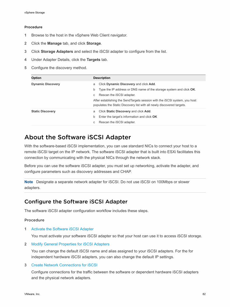
Procedure
1 Browse to the host in the vSphere Web Client navigator.
2 Click the Manage tab, and click Storage.
3 Click Storage Adapters and select the iSCSI adapter to configure from the list.
4 Under Adapter Details, click the Targets tab.
5 Configure the discovery method.
Option Description
Dynamic Discovery a Click Dynamic Discovery and click Add.
b Type the IP address or DNS name of the storage system and click OK.
c Rescan the iSCSI adapter.
After establishing the SendTargets session with the iSCSI system, you hostpopulates the Static Discovery list with all newly discovered targets.
Static Discovery a Click Static Discovery and click Add.
b Enter the target’s information and click OKc Rescan the iSCSI adapter.
About the Software iSCSI AdapterWith the software-based iSCSI implementation, you can use standard NICs to connect your host to aremote iSCSI target on the IP network. The software iSCSI adapter that is built into ESXi facilitates thisconnection by communicating with the physical NICs through the network stack.
Before you can use the software iSCSI adapter, you must set up networking, activate the adapter, andconfigure parameters such as discovery addresses and CHAP.
Note Designate a separate network adapter for iSCSI. Do not use iSCSI on 100Mbps or sloweradapters.
Configure the Software iSCSI AdapterThe software iSCSI adapter configuration workflow includes these steps.
Procedure
1 Activate the Software iSCSI Adapter
You must activate your software iSCSI adapter so that your host can use it to access iSCSI storage.
2 Modify General Properties for iSCSI Adapters
You can change the default iSCSI name and alias assigned to your iSCSI adapters. For the forindependent hardware iSCSI adapters, you can also change the default IP settings.
3 Create Network Connections for iSCSI
Configure connections for the traffic between the software or dependent hardware iSCSI adaptersand the physical network adapters.
vSphere Storage
VMware, Inc. 82
4 Set Up Dynamic or Static Discovery for iSCSI
With dynamic discovery, each time the initiator contacts a specified iSCSI storage system, it sendsthe SendTargets request to the system. The iSCSI system responds by supplying a list of availabletargets to the initiator. In addition to the dynamic discovery method, you can use static discovery andmanually enter information for the targets.
What to do next
If required, configure CHAP parameters and jumbo frames.
Activate the Software iSCSI AdapterYou must activate your software iSCSI adapter so that your host can use it to access iSCSI storage.
You can activate only one software iSCSI adapter.
Prerequisites
Required privilege: Host.Configuration.Storage Partition Configuration
Note If you boot from iSCSI using the software iSCSI adapter, the adapter is enabled and the networkconfiguration is created at the first boot. If you disable the adapter, it is reenabled each time you boot thehost.
Procedure
1 Browse to the host in the vSphere Web Client navigator.
2 Click the Manage tab, and click Storage.
3 Click Storage Adapters, and click Add.
4 Select Software iSCSI Adapter and confirm that you want to add the adapter.
The software iSCSI adapter (vmhba#) is enabled and appears on the list of storage adapters. Afterenabling the adapter, the host assigns the default iSCSI name to it. If you need to change the defaultname, follow iSCSI naming conventions.
What to do next
Select the adapter and use the Adapter Details section to complete configuration.
Modify General Properties for iSCSI AdaptersYou can change the default iSCSI name and alias assigned to your iSCSI adapters. For the forindependent hardware iSCSI adapters, you can also change the default IP settings.
Important When you modify any default properties for your iSCSI adapters, make sure to correctlyformat their names and IP addresses.
Prerequisites
Required privilege: Host .Configuration.Storage Partition Configuration
vSphere Storage
VMware, Inc. 83
Procedure
1 Browse to the host in the vSphere Web Client navigator.
2 Click the Manage tab, and click Storage.
3 Click Storage Adapters, and select the adapter (vmhba#) to configure.
4 Under Adapter Details, click the Properties tab and click Edit in the General panel.
5 To change the default iSCSI name for your adapter, enter the new name.
Make sure the name you enter is worldwide unique and properly formatted or some storage devicesmight not recognize the iSCSI adapter.
6 (Optional) Enter the iSCSI alias.
The alias is a name that you use to identify the iSCSI adapter.
If you change the iSCSI name, it will be used for new iSCSI sessions. For existing sessions, new settingswill not be used until logout and re-login.
Create Network Connections for iSCSIConfigure connections for the traffic between the software or dependent hardware iSCSI adapters and thephysical network adapters.
The following tasks discuss the iSCSI network configuration with a vSphere standard switch.
If you use a vSphere distributed switch with multiple uplink ports, for port binding, create a separatedistributed port group per each physical NIC. Then set the team policy so that each distributed port grouphas only one active uplink port. For detailed information on vSphere distributed switches, see the vSphereNetworking documentation.
Procedure
1 Create a Single VMkernel Adapter for iSCSI
Connect the VMkernel, which runs services for iSCSI storage, to a physical network adapter.
2 Create Additional VMkernel Adapters for iSCSI
Use this task if you have two or more physical network adapters for iSCSI and you want to connectall of your physical adapters to a single vSphere standard switch. In this task, you add the physicaladapters and VMkernel adapters to an existing vSphere standard switch.
3 Change Network Policy for iSCSI
If you use a single vSphere standard switch to connect multiple VMkernel adapters to multiplenetwork adapters, set up network policy so that only one physical network adapter is active for eachVMkernel adapter.
4 Bind iSCSI and VMkernel Adapters
Bind an iSCSI adapter with a VMkernel adapter.
5 Review Port Binding Details
Review networking details of the VMkernel adapter that is bound to the iSCSI adapter.
vSphere Storage
VMware, Inc. 84
Create a Single VMkernel Adapter for iSCSI
Connect the VMkernel, which runs services for iSCSI storage, to a physical network adapter.
Procedure
1 Browse to the host in the vSphere Web Client navigator.
2 Click Actions > Add Networking.
3 Select VMkernel Network Adapter, and click Next.
4 Select New standard switch to create a vSphere standard switch.
5 Click the Add adapters icon, and select the network adapter (vmnic#) to use for iSCSI.
Make sure to assign the adapter to Active Adapters.
Important If you are creating a VMkernel adapter for dependent hardware iSCSI, select the networkadapter that corresponds to the iSCSI component. See Determine Association Between iSCSI andNetwork Adapters.
6 Enter a network label.
A network label is a friendly name that identifies the VMkernel adapter that you are creating, forexample, iSCSI.
7 Specify the IP settings.
8 Review the information and click Finish.
You created the virtual VMkernel adapter (vmk#) for a physical network adapter (vmnic#) on your host.
What to do next
If your host has one physical network adapter for iSCSI traffic, you must bind the virtual adapter that youcreated to the iSCSI adapter.
If you have multiple network adapters, create additional VMkernel adapters and then perform iSCSIbinding. The number of virtual adapters must correspond to the number of physical adapters on the host.
Create Additional VMkernel Adapters for iSCSI
Use this task if you have two or more physical network adapters for iSCSI and you want to connect all ofyour physical adapters to a single vSphere standard switch. In this task, you add the physical adaptersand VMkernel adapters to an existing vSphere standard switch.
Prerequisites
Create a vSphere standard switch that maps an iSCSI VMkernel adapter to a single physical networkadapter designated for iSCSI traffic.
Procedure
1 Browse to the host in the vSphere Web Client navigator.
2 Click the Manage tab, and click Networking.
vSphere Storage
VMware, Inc. 85
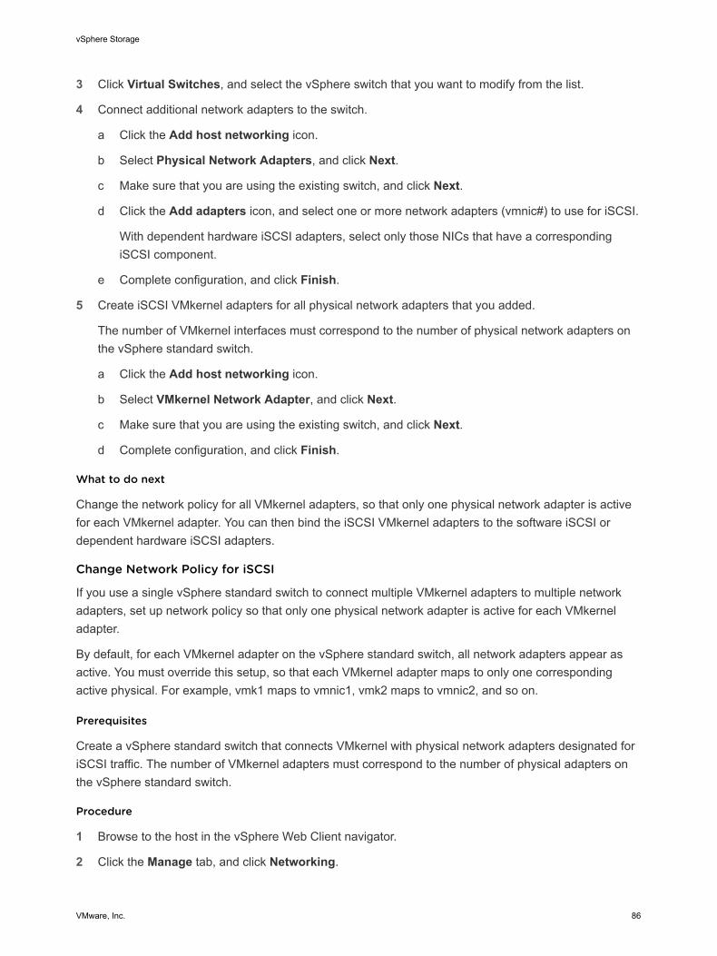
3 Click Virtual Switches, and select the vSphere switch that you want to modify from the list.
4 Connect additional network adapters to the switch.
a Click the Add host networking icon.
b Select Physical Network Adapters, and click Next.
c Make sure that you are using the existing switch, and click Next.
d Click the Add adapters icon, and select one or more network adapters (vmnic#) to use for iSCSI.
With dependent hardware iSCSI adapters, select only those NICs that have a correspondingiSCSI component.
e Complete configuration, and click Finish.
5 Create iSCSI VMkernel adapters for all physical network adapters that you added.
The number of VMkernel interfaces must correspond to the number of physical network adapters onthe vSphere standard switch.
a Click the Add host networking icon.
b Select VMkernel Network Adapter, and click Next.
c Make sure that you are using the existing switch, and click Next.
d Complete configuration, and click Finish.
What to do next
Change the network policy for all VMkernel adapters, so that only one physical network adapter is activefor each VMkernel adapter. You can then bind the iSCSI VMkernel adapters to the software iSCSI ordependent hardware iSCSI adapters.
Change Network Policy for iSCSI
If you use a single vSphere standard switch to connect multiple VMkernel adapters to multiple networkadapters, set up network policy so that only one physical network adapter is active for each VMkerneladapter.
By default, for each VMkernel adapter on the vSphere standard switch, all network adapters appear asactive. You must override this setup, so that each VMkernel adapter maps to only one correspondingactive physical. For example, vmk1 maps to vmnic1, vmk2 maps to vmnic2, and so on.
Prerequisites
Create a vSphere standard switch that connects VMkernel with physical network adapters designated foriSCSI traffic. The number of VMkernel adapters must correspond to the number of physical adapters onthe vSphere standard switch.
Procedure
1 Browse to the host in the vSphere Web Client navigator.
2 Click the Manage tab, and click Networking.
vSphere Storage
VMware, Inc. 86
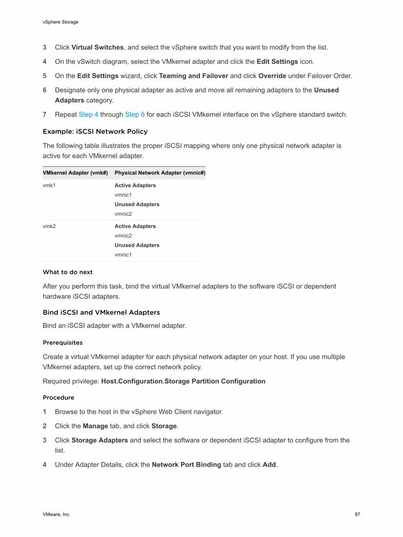
3 Click Virtual Switches, and select the vSphere switch that you want to modify from the list.
4 On the vSwitch diagram, select the VMkernel adapter and click the Edit Settings icon.
5 On the Edit Settings wizard, click Teaming and Failover and click Override under Failover Order.
6 Designate only one physical adapter as active and move all remaining adapters to the UnusedAdapters category.
7 Repeat Step 4 through Step 6 for each iSCSI VMkernel interface on the vSphere standard switch.
Example: iSCSI Network Policy
The following table illustrates the proper iSCSI mapping where only one physical network adapter isactive for each VMkernel adapter.
VMkernel Adapter (vmk#) Physical Network Adapter (vmnic#)
vmk1 Active Adaptersvmnic1
Unused Adaptersvmnic2
vmk2 Active Adaptersvmnic2
Unused Adaptersvmnic1
What to do next
After you perform this task, bind the virtual VMkernel adapters to the software iSCSI or dependenthardware iSCSI adapters.
Bind iSCSI and VMkernel Adapters
Bind an iSCSI adapter with a VMkernel adapter.
Prerequisites
Create a virtual VMkernel adapter for each physical network adapter on your host. If you use multipleVMkernel adapters, set up the correct network policy.
Required privilege: Host.Configuration.Storage Partition Configuration
Procedure
1 Browse to the host in the vSphere Web Client navigator.
2 Click the Manage tab, and click Storage.
3 Click Storage Adapters and select the software or dependent iSCSI adapter to configure from thelist.
4 Under Adapter Details, click the Network Port Binding tab and click Add.
vSphere Storage
VMware, Inc. 87
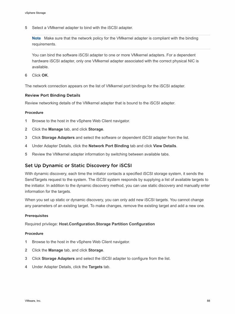
5 Select a VMkernel adapter to bind with the iSCSI adapter.
Note Make sure that the network policy for the VMkernel adapter is compliant with the bindingrequirements.
You can bind the software iSCSI adapter to one or more VMkernel adapters. For a dependenthardware iSCSI adapter, only one VMkernel adapter associated with the correct physical NIC isavailable.
6 Click OK.
The network connection appears on the list of VMkernel port bindings for the iSCSI adapter.
Review Port Binding Details
Review networking details of the VMkernel adapter that is bound to the iSCSI adapter.
Procedure
1 Browse to the host in the vSphere Web Client navigator.
2 Click the Manage tab, and click Storage.
3 Click Storage Adapters and select the software or dependent iSCSI adapter from the list.
4 Under Adapter Details, click the Network Port Binding tab and click View Details.
5 Review the VMkernel adapter information by switching between available tabs.
Set Up Dynamic or Static Discovery for iSCSIWith dynamic discovery, each time the initiator contacts a specified iSCSI storage system, it sends theSendTargets request to the system. The iSCSI system responds by supplying a list of available targets tothe initiator. In addition to the dynamic discovery method, you can use static discovery and manually enterinformation for the targets.
When you set up static or dynamic discovery, you can only add new iSCSI targets. You cannot changeany parameters of an existing target. To make changes, remove the existing target and add a new one.
Prerequisites
Required privilege: Host.Configuration.Storage Partition Configuration
Procedure
1 Browse to the host in the vSphere Web Client navigator.
2 Click the Manage tab, and click Storage.
3 Click Storage Adapters and select the iSCSI adapter to configure from the list.
4 Under Adapter Details, click the Targets tab.
vSphere Storage
VMware, Inc. 88
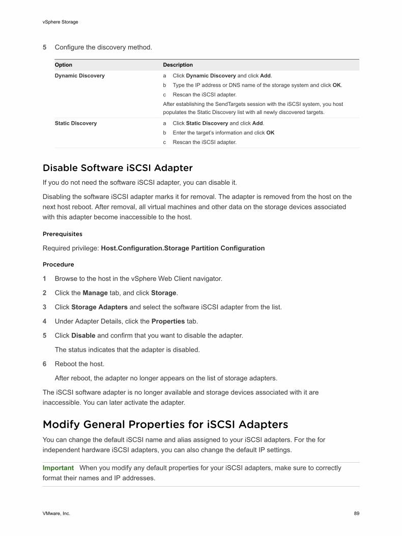
5 Configure the discovery method.
Option Description
Dynamic Discovery a Click Dynamic Discovery and click Add.
b Type the IP address or DNS name of the storage system and click OK.
c Rescan the iSCSI adapter.
After establishing the SendTargets session with the iSCSI system, you hostpopulates the Static Discovery list with all newly discovered targets.
Static Discovery a Click Static Discovery and click Add.
b Enter the target’s information and click OKc Rescan the iSCSI adapter.
Disable Software iSCSI AdapterIf you do not need the software iSCSI adapter, you can disable it.
Disabling the software iSCSI adapter marks it for removal. The adapter is removed from the host on thenext host reboot. After removal, all virtual machines and other data on the storage devices associatedwith this adapter become inaccessible to the host.
Prerequisites
Required privilege: Host.Configuration.Storage Partition Configuration
Procedure
1 Browse to the host in the vSphere Web Client navigator.
2 Click the Manage tab, and click Storage.
3 Click Storage Adapters and select the software iSCSI adapter from the list.
4 Under Adapter Details, click the Properties tab.
5 Click Disable and confirm that you want to disable the adapter.
The status indicates that the adapter is disabled.
6 Reboot the host.
After reboot, the adapter no longer appears on the list of storage adapters.
The iSCSI software adapter is no longer available and storage devices associated with it areinaccessible. You can later activate the adapter.
Modify General Properties for iSCSI AdaptersYou can change the default iSCSI name and alias assigned to your iSCSI adapters. For the forindependent hardware iSCSI adapters, you can also change the default IP settings.
Important When you modify any default properties for your iSCSI adapters, make sure to correctlyformat their names and IP addresses.
vSphere Storage
VMware, Inc. 89
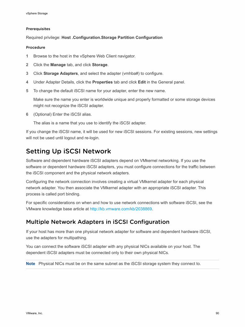
Prerequisites
Required privilege: Host .Configuration.Storage Partition Configuration
Procedure
1 Browse to the host in the vSphere Web Client navigator.
2 Click the Manage tab, and click Storage.
3 Click Storage Adapters, and select the adapter (vmhba#) to configure.
4 Under Adapter Details, click the Properties tab and click Edit in the General panel.
5 To change the default iSCSI name for your adapter, enter the new name.
Make sure the name you enter is worldwide unique and properly formatted or some storage devicesmight not recognize the iSCSI adapter.
6 (Optional) Enter the iSCSI alias.
The alias is a name that you use to identify the iSCSI adapter.
If you change the iSCSI name, it will be used for new iSCSI sessions. For existing sessions, new settingswill not be used until logout and re-login.
Setting Up iSCSI NetworkSoftware and dependent hardware iSCSI adapters depend on VMkernel networking. If you use thesoftware or dependent hardware iSCSI adapters, you must configure connections for the traffic betweenthe iSCSI component and the physical network adapters.
Configuring the network connection involves creating a virtual VMkernel adapter for each physicalnetwork adapter. You then associate the VMkernel adapter with an appropriate iSCSI adapter. Thisprocess is called port binding.
For specific considerations on when and how to use network connections with software iSCSI, see theVMware knowledge base article at http://kb.vmware.com/kb/2038869.
Multiple Network Adapters in iSCSI ConfigurationIf your host has more than one physical network adapter for software and dependent hardware iSCSI,use the adapters for multipathing.
You can connect the software iSCSI adapter with any physical NICs available on your host. Thedependent iSCSI adapters must be connected only to their own physical NICs.
Note Physical NICs must be on the same subnet as the iSCSI storage system they connect to.
vSphere Storage
VMware, Inc. 90
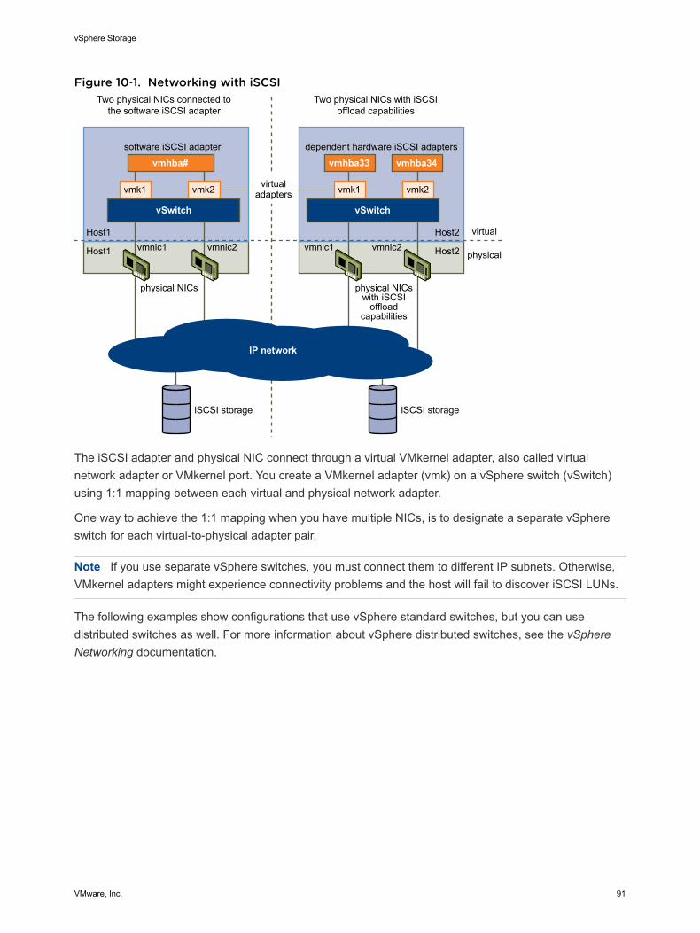
Figure 10‑1. Networking with iSCSI
physical NICs
vmnic1 vmnic2 vmnic1 vmnic2
physical NICswith iSCSI
offloadcapabilities
Host1
Host1
Host2
Host2
virtualadapters
software iSCSI adapter dependent hardware iSCSI adapters
vSwitch
vmk1 vmk2 vmk1
vmhba33vmhba# vmhba34
vmk2
vSwitch
virtual
physical
Two physical NICs connected tothe software iSCSI adapter
Two physical NICs with iSCSIoffload capabilities
IP network
iSCSI storage iSCSI storage
The iSCSI adapter and physical NIC connect through a virtual VMkernel adapter, also called virtualnetwork adapter or VMkernel port. You create a VMkernel adapter (vmk) on a vSphere switch (vSwitch)using 1:1 mapping between each virtual and physical network adapter.
One way to achieve the 1:1 mapping when you have multiple NICs, is to designate a separate vSphereswitch for each virtual-to-physical adapter pair.
Note If you use separate vSphere switches, you must connect them to different IP subnets. Otherwise,VMkernel adapters might experience connectivity problems and the host will fail to discover iSCSI LUNs.
The following examples show configurations that use vSphere standard switches, but you can usedistributed switches as well. For more information about vSphere distributed switches, see the vSphereNetworking documentation.
vSphere Storage
VMware, Inc. 91
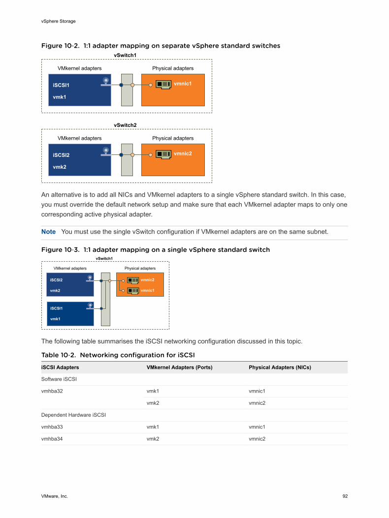
Figure 10‑2. 1:1 adapter mapping on separate vSphere standard switches
VMkernel adapters Physical adapters
vmnic1iSCSI1
vmk1
vSwitch1
VMkernel adapters Physical adapters
vmnic2iSCSI2
vmk2
vSwitch2
An alternative is to add all NICs and VMkernel adapters to a single vSphere standard switch. In this case,you must override the default network setup and make sure that each VMkernel adapter maps to only onecorresponding active physical adapter.
Note You must use the single vSwitch configuration if VMkernel adapters are on the same subnet.
Figure 10‑3. 1:1 adapter mapping on a single vSphere standard switch
VMkernel adapters Physical adapters
vmnic2
vmnic1
iSCSI2
vmk2
iSCSI1
vmk1
vSwitch1
The following table summarises the iSCSI networking configuration discussed in this topic.
Table 10‑2. Networking configuration for iSCSI
iSCSI Adapters VMkernel Adapters (Ports) Physical Adapters (NICs)
Software iSCSI
vmhba32 vmk1 vmnic1
vmk2 vmnic2
Dependent Hardware iSCSI
vmhba33 vmk1 vmnic1
vmhba34 vmk2 vmnic2
vSphere Storage
VMware, Inc. 92
Guidelines for Using iSCSI Port Binding in ESXiYou can use multiple VMkernel adapters bound to iSCSI to have multiple paths to an iSCSI array thatbroadcasts a single IP address.
When you use port binding for multipathing, follow these guidelines:
n iSCSI ports of the array target must reside in the same broadcast domain and IP subnet as theVMkernel adapters.
n All VMkernel adapters used for iSCSI port binding must reside in the same broadcast domain and IPsubnet.
n All VMkernel adapters used for iSCSI connectivity must reside in the same virtual switch.
n Port binding does not support network routing.
Do not use port binding when any of the following conditions exist:
n Array target iSCSI ports are in a different broadcast domain and IP subnet.
n VMkernel adapters used for iSCSI connectivity exist in different broadcast domains, IP subnets, oruse different virtual switches.
n Routing is required to reach the iSCSI array.
Create Network Connections for iSCSIConfigure connections for the traffic between the software or dependent hardware iSCSI adapters and thephysical network adapters.
The following tasks discuss the iSCSI network configuration with a vSphere standard switch.
If you use a vSphere distributed switch with multiple uplink ports, for port binding, create a separatedistributed port group per each physical NIC. Then set the team policy so that each distributed port grouphas only one active uplink port. For detailed information on vSphere distributed switches, see the vSphereNetworking documentation.
Procedure
1 Create a Single VMkernel Adapter for iSCSI
Connect the VMkernel, which runs services for iSCSI storage, to a physical network adapter.
2 Create Additional VMkernel Adapters for iSCSI
Use this task if you have two or more physical network adapters for iSCSI and you want to connectall of your physical adapters to a single vSphere standard switch. In this task, you add the physicaladapters and VMkernel adapters to an existing vSphere standard switch.
3 Change Network Policy for iSCSI
If you use a single vSphere standard switch to connect multiple VMkernel adapters to multiplenetwork adapters, set up network policy so that only one physical network adapter is active for eachVMkernel adapter.
vSphere Storage
VMware, Inc. 93
4 Bind iSCSI and VMkernel Adapters
Bind an iSCSI adapter with a VMkernel adapter.
5 Review Port Binding Details
Review networking details of the VMkernel adapter that is bound to the iSCSI adapter.
Create a Single VMkernel Adapter for iSCSIConnect the VMkernel, which runs services for iSCSI storage, to a physical network adapter.
Procedure
1 Browse to the host in the vSphere Web Client navigator.
2 Click Actions > Add Networking.
3 Select VMkernel Network Adapter, and click Next.
4 Select New standard switch to create a vSphere standard switch.
5 Click the Add adapters icon, and select the network adapter (vmnic#) to use for iSCSI.
Make sure to assign the adapter to Active Adapters.
Important If you are creating a VMkernel adapter for dependent hardware iSCSI, select the networkadapter that corresponds to the iSCSI component. See Determine Association Between iSCSI andNetwork Adapters.
6 Enter a network label.
A network label is a friendly name that identifies the VMkernel adapter that you are creating, forexample, iSCSI.
7 Specify the IP settings.
8 Review the information and click Finish.
You created the virtual VMkernel adapter (vmk#) for a physical network adapter (vmnic#) on your host.
What to do next
If your host has one physical network adapter for iSCSI traffic, you must bind the virtual adapter that youcreated to the iSCSI adapter.
If you have multiple network adapters, create additional VMkernel adapters and then perform iSCSIbinding. The number of virtual adapters must correspond to the number of physical adapters on the host.
Create Additional VMkernel Adapters for iSCSIUse this task if you have two or more physical network adapters for iSCSI and you want to connect all ofyour physical adapters to a single vSphere standard switch. In this task, you add the physical adaptersand VMkernel adapters to an existing vSphere standard switch.
vSphere Storage
VMware, Inc. 94
Prerequisites
Create a vSphere standard switch that maps an iSCSI VMkernel adapter to a single physical networkadapter designated for iSCSI traffic.
Procedure
1 Browse to the host in the vSphere Web Client navigator.
2 Click the Manage tab, and click Networking.
3 Click Virtual Switches, and select the vSphere switch that you want to modify from the list.
4 Connect additional network adapters to the switch.
a Click the Add host networking icon.
b Select Physical Network Adapters, and click Next.
c Make sure that you are using the existing switch, and click Next.
d Click the Add adapters icon, and select one or more network adapters (vmnic#) to use for iSCSI.
With dependent hardware iSCSI adapters, select only those NICs that have a correspondingiSCSI component.
e Complete configuration, and click Finish.
5 Create iSCSI VMkernel adapters for all physical network adapters that you added.
The number of VMkernel interfaces must correspond to the number of physical network adapters onthe vSphere standard switch.
a Click the Add host networking icon.
b Select VMkernel Network Adapter, and click Next.
c Make sure that you are using the existing switch, and click Next.
d Complete configuration, and click Finish.
What to do next
Change the network policy for all VMkernel adapters, so that only one physical network adapter is activefor each VMkernel adapter. You can then bind the iSCSI VMkernel adapters to the software iSCSI ordependent hardware iSCSI adapters.
Change Network Policy for iSCSIIf you use a single vSphere standard switch to connect multiple VMkernel adapters to multiple networkadapters, set up network policy so that only one physical network adapter is active for each VMkerneladapter.
By default, for each VMkernel adapter on the vSphere standard switch, all network adapters appear asactive. You must override this setup, so that each VMkernel adapter maps to only one correspondingactive physical. For example, vmk1 maps to vmnic1, vmk2 maps to vmnic2, and so on.
vSphere Storage
VMware, Inc. 95
Prerequisites
Create a vSphere standard switch that connects VMkernel with physical network adapters designated foriSCSI traffic. The number of VMkernel adapters must correspond to the number of physical adapters onthe vSphere standard switch.
Procedure
1 Browse to the host in the vSphere Web Client navigator.
2 Click the Manage tab, and click Networking.
3 Click Virtual Switches, and select the vSphere switch that you want to modify from the list.
4 On the vSwitch diagram, select the VMkernel adapter and click the Edit Settings icon.
5 On the Edit Settings wizard, click Teaming and Failover and click Override under Failover Order.
6 Designate only one physical adapter as active and move all remaining adapters to the UnusedAdapters category.
7 Repeat Step 4 through Step 6 for each iSCSI VMkernel interface on the vSphere standard switch.
Example: iSCSI Network Policy
The following table illustrates the proper iSCSI mapping where only one physical network adapter isactive for each VMkernel adapter.
VMkernel Adapter (vmk#) Physical Network Adapter (vmnic#)
vmk1 Active Adaptersvmnic1
Unused Adaptersvmnic2
vmk2 Active Adaptersvmnic2
Unused Adaptersvmnic1
What to do next
After you perform this task, bind the virtual VMkernel adapters to the software iSCSI or dependenthardware iSCSI adapters.
Bind iSCSI and VMkernel AdaptersBind an iSCSI adapter with a VMkernel adapter.
Prerequisites
Create a virtual VMkernel adapter for each physical network adapter on your host. If you use multipleVMkernel adapters, set up the correct network policy.
Required privilege: Host.Configuration.Storage Partition Configuration
vSphere Storage
VMware, Inc. 96
Procedure
1 Browse to the host in the vSphere Web Client navigator.
2 Click the Manage tab, and click Storage.
3 Click Storage Adapters and select the software or dependent iSCSI adapter to configure from thelist.
4 Under Adapter Details, click the Network Port Binding tab and click Add.
5 Select a VMkernel adapter to bind with the iSCSI adapter.
Note Make sure that the network policy for the VMkernel adapter is compliant with the bindingrequirements.
You can bind the software iSCSI adapter to one or more VMkernel adapters. For a dependenthardware iSCSI adapter, only one VMkernel adapter associated with the correct physical NIC isavailable.
6 Click OK.
The network connection appears on the list of VMkernel port bindings for the iSCSI adapter.
Review Port Binding DetailsReview networking details of the VMkernel adapter that is bound to the iSCSI adapter.
Procedure
1 Browse to the host in the vSphere Web Client navigator.
2 Click the Manage tab, and click Storage.
3 Click Storage Adapters and select the software or dependent iSCSI adapter from the list.
4 Under Adapter Details, click the Network Port Binding tab and click View Details.
5 Review the VMkernel adapter information by switching between available tabs.
Managing iSCSI NetworkSpecial consideration apply to network adapters, both physical and VMkernel, that are associated with aniSCSI adapter.
After you create network connections for iSCSI, an iSCSI indicator on a number of Networking dialogboxes becomes enabled. This indicator shows that a particular virtual or physical network adapter isiSCSI-bound. To avoid disruptions in iSCSI traffic, follow these guidelines and considerations whenmanaging iSCSI-bound virtual and physical network adapters:
n Make sure that the VMkernel network adapters are assigned addresses on the same subnet as theiSCSI storage portal they connect to.
n iSCSI adapters using VMkernel adapters are not able to connect to iSCSI ports on different subnets,even if those ports are discovered by the iSCSI adapters.
vSphere Storage
VMware, Inc. 97
n When using separate vSphere switches to connect physical network adapters and VMkerneladapters, make sure that the vSphere switches connect to different IP subnets.
n If VMkernel adapters are on the same subnet, they must connect to a single vSwitch.
n If you migrate VMkernel adapters to a different vSphere switch, move associated physical adapters.
n Do not make configuration changes to iSCSI-bound VMkernel adapters or physical network adapters.
n Do not make changes that might break association of VMkernel adapters and physical networkadapters. You can break the association if you remove one of the adapters or the vSphere switch thatconnects them, or change the 1:1 network policy for their connection.
iSCSI Network TroubleshootingA warning sign indicates non-compliant port group policy for an iSCSI-bound VMkernel adapter.
Problem
The VMkernel adapter's port group policy is considered non-compliant in the following cases:
n The VMkernel adapter is not connected to an active physical network adapter.
n The VMkernel adapter is connected to more than one physical network adapter.
n The VMkernel adapter is connected to one or more standby physical adapters.
n The active physical adapter is changed.
Solution
Follow the steps in Change Network Policy for iSCSI to set up the correct network policy for the iSCSI-bound VMkernel adapter.
Using Jumbo Frames with iSCSIESXi supports the use of Jumbo Frames with iSCSI.
Jumbo Frames are Ethernet frames with the size that exceeds 1500 Bytes. The maximum transmissionunit (MTU) parameter is typically used to measure the size of Jumbo Frames. ESXi allows Jumbo Frameswith the MTU up to 9000 Bytes.
When you use Jumbo Frames for iSCSI traffic, the following considerations apply:
n The network must support Jumbo Frames end-to-end for Jumbo Frames to be effective.
n Check with your vendors to ensure your physical NICs and iSCSI HBAs support Jumbo Frames.
n To set up and verify physical network switches for Jumbo Frames, consult your vendordocumentation.
The following table explains the level of support that ESXi provides to Jumbo Frames.
vSphere Storage
VMware, Inc. 98
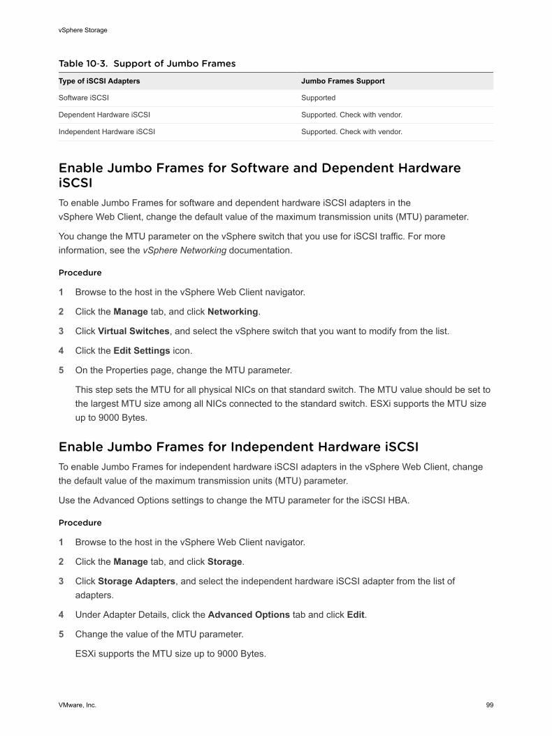
Table 10‑3. Support of Jumbo Frames
Type of iSCSI Adapters Jumbo Frames Support
Software iSCSI Supported
Dependent Hardware iSCSI Supported. Check with vendor.
Independent Hardware iSCSI Supported. Check with vendor.
Enable Jumbo Frames for Software and Dependent HardwareiSCSITo enable Jumbo Frames for software and dependent hardware iSCSI adapters in thevSphere Web Client, change the default value of the maximum transmission units (MTU) parameter.
You change the MTU parameter on the vSphere switch that you use for iSCSI traffic. For moreinformation, see the vSphere Networking documentation.
Procedure
1 Browse to the host in the vSphere Web Client navigator.
2 Click the Manage tab, and click Networking.
3 Click Virtual Switches, and select the vSphere switch that you want to modify from the list.
4 Click the Edit Settings icon.
5 On the Properties page, change the MTU parameter.
This step sets the MTU for all physical NICs on that standard switch. The MTU value should be set tothe largest MTU size among all NICs connected to the standard switch. ESXi supports the MTU sizeup to 9000 Bytes.
Enable Jumbo Frames for Independent Hardware iSCSITo enable Jumbo Frames for independent hardware iSCSI adapters in the vSphere Web Client, changethe default value of the maximum transmission units (MTU) parameter.
Use the Advanced Options settings to change the MTU parameter for the iSCSI HBA.
Procedure
1 Browse to the host in the vSphere Web Client navigator.
2 Click the Manage tab, and click Storage.
3 Click Storage Adapters, and select the independent hardware iSCSI adapter from the list ofadapters.
4 Under Adapter Details, click the Advanced Options tab and click Edit.
5 Change the value of the MTU parameter.
ESXi supports the MTU size up to 9000 Bytes.
vSphere Storage
VMware, Inc. 99
Configuring Discovery Addresses for iSCSI AdaptersYou need to set up target discovery addresses, so that the iSCSI adapter can determine which storageresource on the network is available for access.
The ESXi system supports these discovery methods:
Dynamic Discovery Also known as SendTargets discovery. Each time the initiator contacts aspecified iSCSI server, the initiator sends the SendTargets request to theserver. The server responds by supplying a list of available targets to theinitiator. The names and IP addresses of these targets appear on the StaticDiscovery tab. If you remove a static target added by dynamic discovery,the target might be returned to the list the next time a rescan happens, theiSCSI adapter is reset, or the host is rebooted.
Note With software and dependent hardware iSCSI, ESXi filters targetaddresses based on the IP family of the iSCSI server address specified. Ifthe address is IPv4, IPv6 addresses that might come in the SendTargetsresponse from the iSCSI server are filtered out. When DNS names areused to specify an iSCSI server, or when the SendTargets response fromthe iSCSI server has DNS names, ESXi relies on the IP family of the firstresolved entry from DNS lookup.
Static Discovery In addition to the dynamic discovery method, you can use static discoveryand manually enter information for the targets. The iSCSI adapter uses alist of targets that you provide to contact and communicate with the iSCSIservers.
Set Up Dynamic or Static Discovery for iSCSIWith dynamic discovery, each time the initiator contacts a specified iSCSI storage system, it sends theSendTargets request to the system. The iSCSI system responds by supplying a list of available targets tothe initiator. In addition to the dynamic discovery method, you can use static discovery and manually enterinformation for the targets.
When you set up static or dynamic discovery, you can only add new iSCSI targets. You cannot changeany parameters of an existing target. To make changes, remove the existing target and add a new one.
Prerequisites
Required privilege: Host.Configuration.Storage Partition Configuration
Procedure
1 Browse to the host in the vSphere Web Client navigator.
2 Click the Manage tab, and click Storage.
vSphere Storage
VMware, Inc. 100
3 Click Storage Adapters and select the iSCSI adapter to configure from the list.
4 Under Adapter Details, click the Targets tab.
5 Configure the discovery method.
Option Description
Dynamic Discovery a Click Dynamic Discovery and click Add.
b Type the IP address or DNS name of the storage system and click OK.
c Rescan the iSCSI adapter.
After establishing the SendTargets session with the iSCSI system, you hostpopulates the Static Discovery list with all newly discovered targets.
Static Discovery a Click Static Discovery and click Add.
b Enter the target’s information and click OKc Rescan the iSCSI adapter.
Remove Dynamic or Static iSCSI TargetsRemove iSCSI servers that appear on the list of targets.
Procedure
1 Browse to the host in the vSphere Web Client navigator.
2 Click the Manage tab, and click Storage.
3 Click Storage Adapters and select the iSCSI adapter to modify from the list.
4 Under Adapter Details, click the Targets tab.
5 Switch between Dynamic Discovery and Static Discovery.
6 Select an iSCSI server to remove and click Remove.
7 Rescan the iSCSI adapter.
If you are removing the static target that was dynamically discovered, you need to remove it from thestorage system before performing the rescan. Otherwise, your host will automatically discover andadd the target to the list of static targets when you rescan the adapter.
Configuring CHAP Parameters for iSCSI AdaptersBecause the IP networks that the iSCSI technology uses to connect to remote targets do not protect thedata they transport, you must ensure security of the connection. One of the protocols that iSCSIimplements is the Challenge Handshake Authentication Protocol (CHAP), which verifies the legitimacy ofinitiators that access targets on the network.
CHAP uses a three-way handshake algorithm to verify the identity of your host and, if applicable, of theiSCSI target when the host and target establish a connection. The verification is based on a predefinedprivate value, or CHAP secret, that the initiator and target share.
vSphere Storage
VMware, Inc. 101
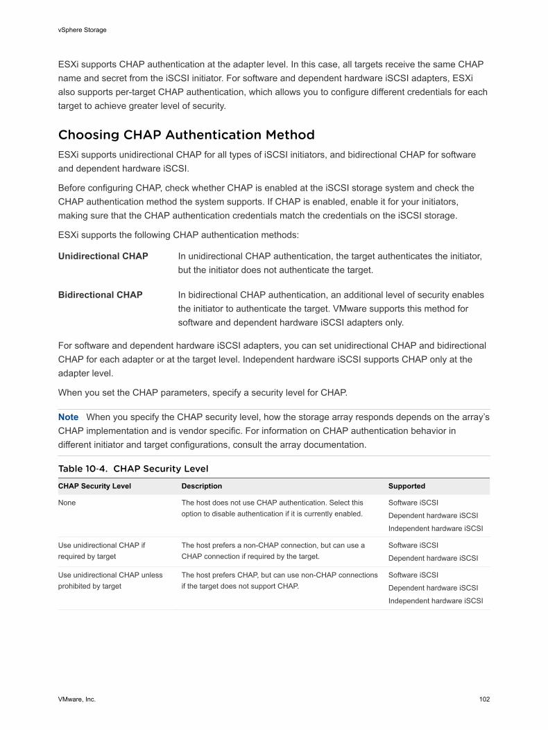
ESXi supports CHAP authentication at the adapter level. In this case, all targets receive the same CHAPname and secret from the iSCSI initiator. For software and dependent hardware iSCSI adapters, ESXialso supports per-target CHAP authentication, which allows you to configure different credentials for eachtarget to achieve greater level of security.
Choosing CHAP Authentication MethodESXi supports unidirectional CHAP for all types of iSCSI initiators, and bidirectional CHAP for softwareand dependent hardware iSCSI.
Before configuring CHAP, check whether CHAP is enabled at the iSCSI storage system and check theCHAP authentication method the system supports. If CHAP is enabled, enable it for your initiators,making sure that the CHAP authentication credentials match the credentials on the iSCSI storage.
ESXi supports the following CHAP authentication methods:
Unidirectional CHAP In unidirectional CHAP authentication, the target authenticates the initiator,but the initiator does not authenticate the target.
Bidirectional CHAP In bidirectional CHAP authentication, an additional level of security enablesthe initiator to authenticate the target. VMware supports this method forsoftware and dependent hardware iSCSI adapters only.
For software and dependent hardware iSCSI adapters, you can set unidirectional CHAP and bidirectionalCHAP for each adapter or at the target level. Independent hardware iSCSI supports CHAP only at theadapter level.
When you set the CHAP parameters, specify a security level for CHAP.
Note When you specify the CHAP security level, how the storage array responds depends on the array’sCHAP implementation and is vendor specific. For information on CHAP authentication behavior indifferent initiator and target configurations, consult the array documentation.
Table 10‑4. CHAP Security Level
CHAP Security Level Description Supported
None The host does not use CHAP authentication. Select thisoption to disable authentication if it is currently enabled.
Software iSCSI
Dependent hardware iSCSI
Independent hardware iSCSI
Use unidirectional CHAP ifrequired by target
The host prefers a non-CHAP connection, but can use aCHAP connection if required by the target.
Software iSCSI
Dependent hardware iSCSI
Use unidirectional CHAP unlessprohibited by target
The host prefers CHAP, but can use non-CHAP connectionsif the target does not support CHAP.
Software iSCSI
Dependent hardware iSCSI
Independent hardware iSCSI
vSphere Storage
VMware, Inc. 102
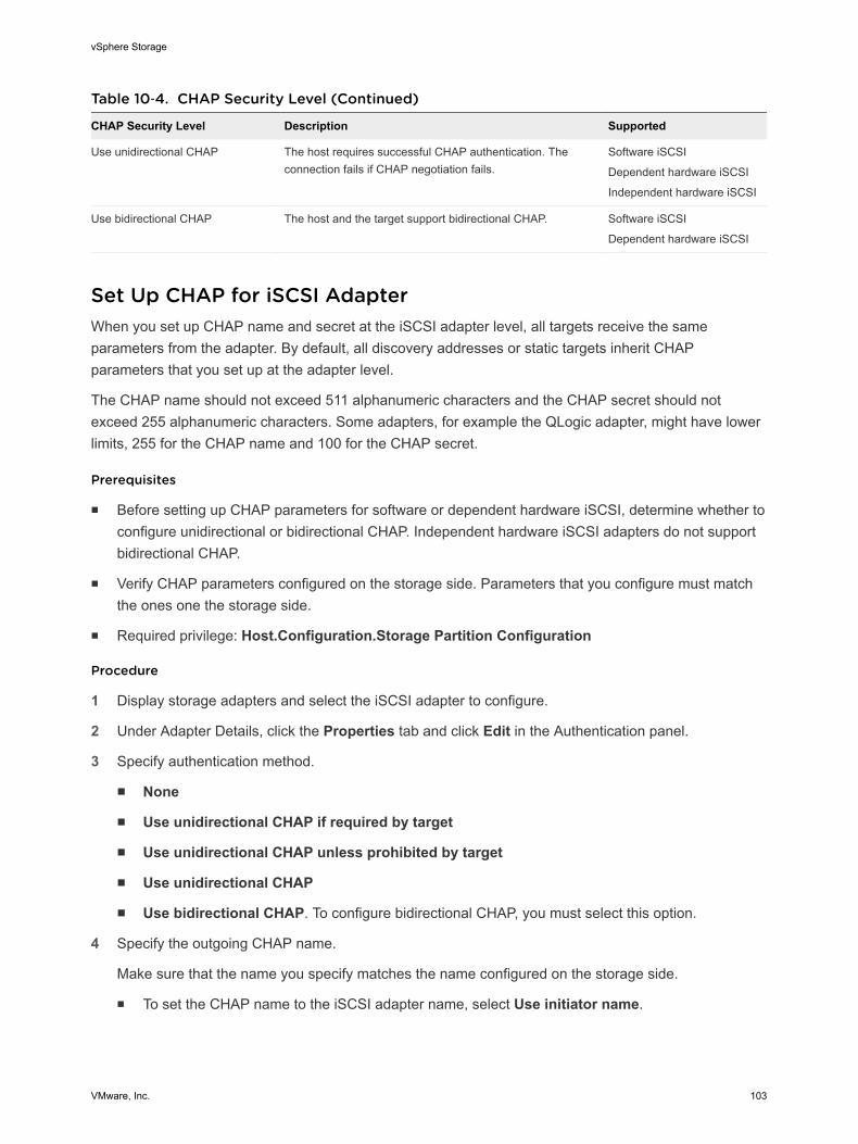
Table 10‑4. CHAP Security Level (Continued)
CHAP Security Level Description Supported
Use unidirectional CHAP The host requires successful CHAP authentication. Theconnection fails if CHAP negotiation fails.
Software iSCSI
Dependent hardware iSCSI
Independent hardware iSCSI
Use bidirectional CHAP The host and the target support bidirectional CHAP. Software iSCSI
Dependent hardware iSCSI
Set Up CHAP for iSCSI AdapterWhen you set up CHAP name and secret at the iSCSI adapter level, all targets receive the sameparameters from the adapter. By default, all discovery addresses or static targets inherit CHAPparameters that you set up at the adapter level.
The CHAP name should not exceed 511 alphanumeric characters and the CHAP secret should notexceed 255 alphanumeric characters. Some adapters, for example the QLogic adapter, might have lowerlimits, 255 for the CHAP name and 100 for the CHAP secret.
Prerequisites
n Before setting up CHAP parameters for software or dependent hardware iSCSI, determine whether toconfigure unidirectional or bidirectional CHAP. Independent hardware iSCSI adapters do not supportbidirectional CHAP.
n Verify CHAP parameters configured on the storage side. Parameters that you configure must matchthe ones one the storage side.
n Required privilege: Host.Configuration.Storage Partition Configuration
Procedure
1 Display storage adapters and select the iSCSI adapter to configure.
2 Under Adapter Details, click the Properties tab and click Edit in the Authentication panel.
3 Specify authentication method.
n None
n Use unidirectional CHAP if required by target
n Use unidirectional CHAP unless prohibited by target
n Use unidirectional CHAP
n Use bidirectional CHAP. To configure bidirectional CHAP, you must select this option.
4 Specify the outgoing CHAP name.
Make sure that the name you specify matches the name configured on the storage side.
n To set the CHAP name to the iSCSI adapter name, select Use initiator name.
vSphere Storage
VMware, Inc. 103
n To set the CHAP name to anything other than the iSCSI initiator name, deselect Use initiatorname and type a name in the Name text box.
5 Enter an outgoing CHAP secret to be used as part of authentication. Use the same secret that youenter on the storage side.
6 If configuring bidirectional CHAP, specify incoming CHAP credentials.
Make sure to use different secrets for the outgoing and incoming CHAP.
7 Click OK.
8 Rescan the iSCSI adapter.
If you change the CHAP parameters, they are used for new iSCSI sessions. For existing sessions, newsettings are not used until you log out and log in again.
Set Up CHAP for TargetIf you use software and dependent hardware iSCSI adapters, you can configure different CHAPcredentials for each discovery address or static target.
The CHAP name should not exceed 511 and the CHAP secret 255 alphanumeric characters.
Prerequisites
n Before setting up CHAP parameters for software or dependent hardware iSCSI, determine whether toconfigure unidirectional or bidirectional CHAP.
n Verify CHAP parameters configured on the storage side. Parameters that you configure must matchthe ones one the storage side.
n Access storage adapters.
n Required privilege: Host.Configuration.Storage Partition Configuration
Procedure
1 Select the iSCSI adapter to configure, and click the Targets tab under Adapter Details.
2 Click either Dynamic Discovery or Static Discovery.
3 From the list of available targets, select a target to configure and click Authentication.
4 Deselect Inherit settings from parent and specify authentication method.
n None
n Use unidirectional CHAP if required by target
n Use unidirectional CHAP unless prohibited by target
n Use unidirectional CHAP
n Use bidirectional CHAP. To configure bidirectional CHAP, you must select this option.
vSphere Storage
VMware, Inc. 104
5 Specify the outgoing CHAP name.
Make sure that the name you specify matches the name configured on the storage side.
n To set the CHAP name to the iSCSI adapter name, select Use initiator name.
n To set the CHAP name to anything other than the iSCSI initiator name, deselect Use initiatorname and type a name in the Name text box.
6 Enter an outgoing CHAP secret to be used as part of authentication. Use the same secret that youenter on the storage side.
7 If configuring bi-directional CHAP, specify incoming CHAP credentials.
Make sure to use different secrets for the outgoing and incoming CHAP.
8 Click OK.
9 Rescan the iSCSI adapter.
If you change the CHAP parameters, they are used for new iSCSI sessions. For existing sessions, newsettings are not used until you log out and login again.
Disable CHAPYou can disable CHAP if your storage system does not require it.
If you disable CHAP on a system that requires CHAP authentication, existing iSCSI sessions remainactive until you reboot your host, end the session through the command line, or the storage system forcesa logout. After the session ends, you can no longer connect to targets that require CHAP.
Required privilege: Host.Configuration.Storage Partition Configuration
Procedure
1 Open the CHAP Credentials dialog box.
2 For software and dependent hardware iSCSI adapters, to disable just the mutual CHAP and leave theone-way CHAP, select Do not use CHAP in the Mutual CHAP area.
3 To disable one-way CHAP, select Do not use CHAP in the CHAP area.
The mutual CHAP, if set up, automatically turns to Do not use CHAP when you disable the one-wayCHAP.
4 Click OK.
Configuring Advanced Parameters for iSCSIYou might need to configure additional parameters for your iSCSI initiators. For example, some iSCSIstorage systems require ARP (Address Resolution Protocol) redirection to move iSCSI traffic dynamicallyfrom one port to another. In this case, you must activate ARP redirection on your host.
vSphere Storage
VMware, Inc. 105
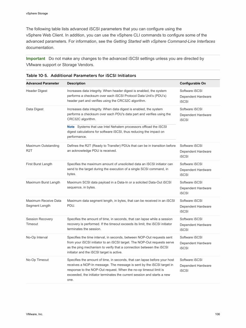
The following table lists advanced iSCSI parameters that you can configure using thevSphere Web Client. In addition, you can use the vSphere CLI commands to configure some of theadvanced parameters. For information, see the Getting Started with vSphere Command-Line Interfacesdocumentation.
Important Do not make any changes to the advanced iSCSI settings unless you are directed byVMware support or Storage Vendors.
Table 10‑5. Additional Parameters for iSCSI Initiators
Advanced Parameter Description Configurable On
Header Digest Increases data integrity. When header digest is enabled, the systemperforms a checksum over each iSCSI Protocol Data Unit’s (PDU’s)header part and verifies using the CRC32C algorithm.
Software iSCSI
Dependent HardwareiSCSI
Data Digest Increases data integrity. When data digest is enabled, the systemperforms a checksum over each PDU's data part and verifies using theCRC32C algorithm.
Note Systems that use Intel Nehalem processors offload the iSCSIdigest calculations for software iSCSI, thus reducing the impact onperformance.
Software iSCSI
Dependent HardwareiSCSI
Maximum OutstandingR2T
Defines the R2T (Ready to Transfer) PDUs that can be in transition beforean acknowledge PDU is received.
Software iSCSI
Dependent HardwareiSCSI
First Burst Length Specifies the maximum amount of unsolicited data an iSCSI initiator cansend to the target during the execution of a single SCSI command, inbytes.
Software iSCSI
Dependent HardwareiSCSI
Maximum Burst Length Maximum SCSI data payload in a Data-In or a solicited Data-Out iSCSIsequence, in bytes.
Software iSCSI
Dependent HardwareiSCSI
Maximum Receive DataSegment Length
Maximum data segment length, in bytes, that can be received in an iSCSIPDU.
Software iSCSI
Dependent HardwareiSCSI
Session RecoveryTimeout
Specifies the amount of time, in seconds, that can lapse while a sessionrecovery is performed. If the timeout exceeds its limit, the iSCSI initiatorterminates the session.
Software iSCSI
Dependent HardwareiSCSI
No-Op Interval Specifies the time interval, in seconds, between NOP-Out requests sentfrom your iSCSI initiator to an iSCSI target. The NOP-Out requests serveas the ping mechanism to verify that a connection between the iSCSIinitiator and the iSCSI target is active.
Software iSCSI
Dependent HardwareiSCSI
No-Op Timeout Specifies the amount of time, in seconds, that can lapse before your hostreceives a NOP-In message. The message is sent by the iSCSI target inresponse to the NOP-Out request. When the no-op timeout limit isexceeded, the initiator terminates the current session and starts a newone.
Software iSCSI
Dependent HardwareiSCSI
vSphere Storage
VMware, Inc. 106
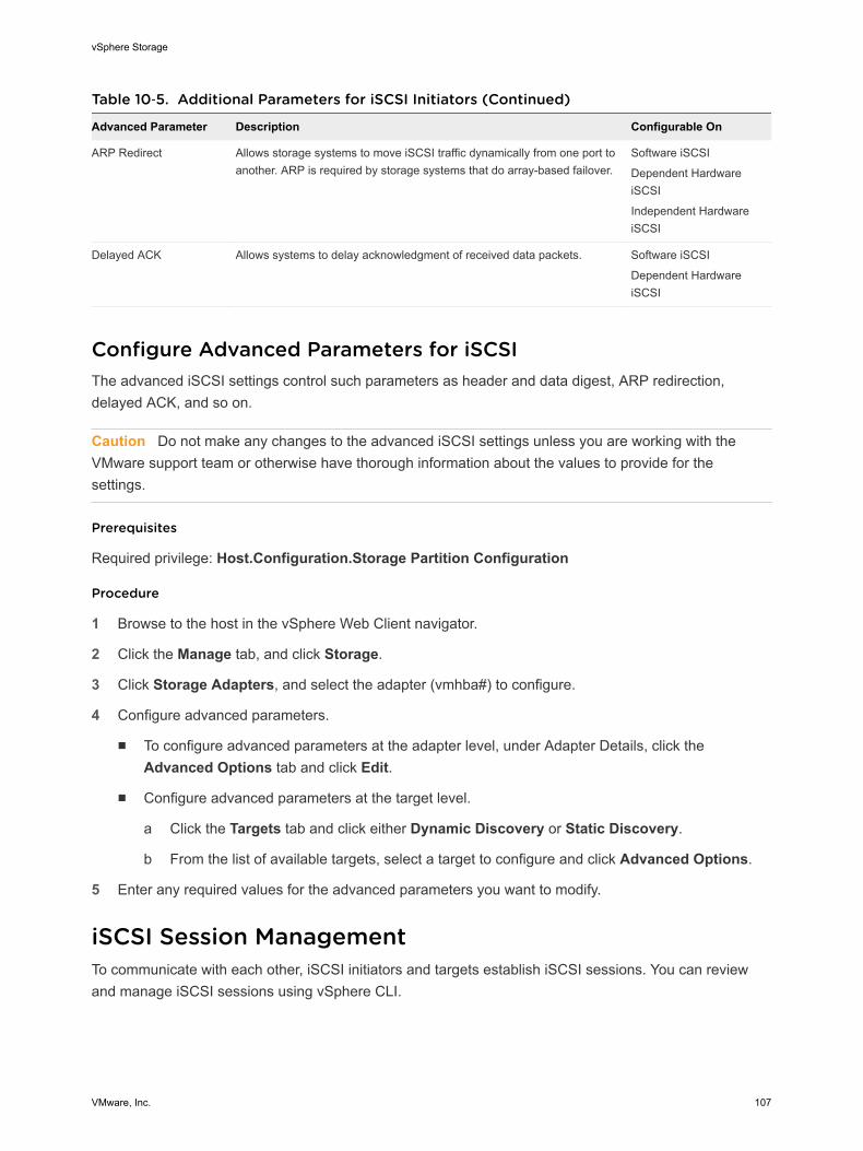
Table 10‑5. Additional Parameters for iSCSI Initiators (Continued)
Advanced Parameter Description Configurable On
ARP Redirect Allows storage systems to move iSCSI traffic dynamically from one port toanother. ARP is required by storage systems that do array-based failover.
Software iSCSI
Dependent HardwareiSCSI
Independent HardwareiSCSI
Delayed ACK Allows systems to delay acknowledgment of received data packets. Software iSCSI
Dependent HardwareiSCSI
Configure Advanced Parameters for iSCSIThe advanced iSCSI settings control such parameters as header and data digest, ARP redirection,delayed ACK, and so on.
Caution Do not make any changes to the advanced iSCSI settings unless you are working with theVMware support team or otherwise have thorough information about the values to provide for thesettings.
Prerequisites
Required privilege: Host.Configuration.Storage Partition Configuration
Procedure
1 Browse to the host in the vSphere Web Client navigator.
2 Click the Manage tab, and click Storage.
3 Click Storage Adapters, and select the adapter (vmhba#) to configure.
4 Configure advanced parameters.
n To configure advanced parameters at the adapter level, under Adapter Details, click theAdvanced Options tab and click Edit.
n Configure advanced parameters at the target level.
a Click the Targets tab and click either Dynamic Discovery or Static Discovery.
b From the list of available targets, select a target to configure and click Advanced Options.
5 Enter any required values for the advanced parameters you want to modify.
iSCSI Session ManagementTo communicate with each other, iSCSI initiators and targets establish iSCSI sessions. You can reviewand manage iSCSI sessions using vSphere CLI.
vSphere Storage
VMware, Inc. 107
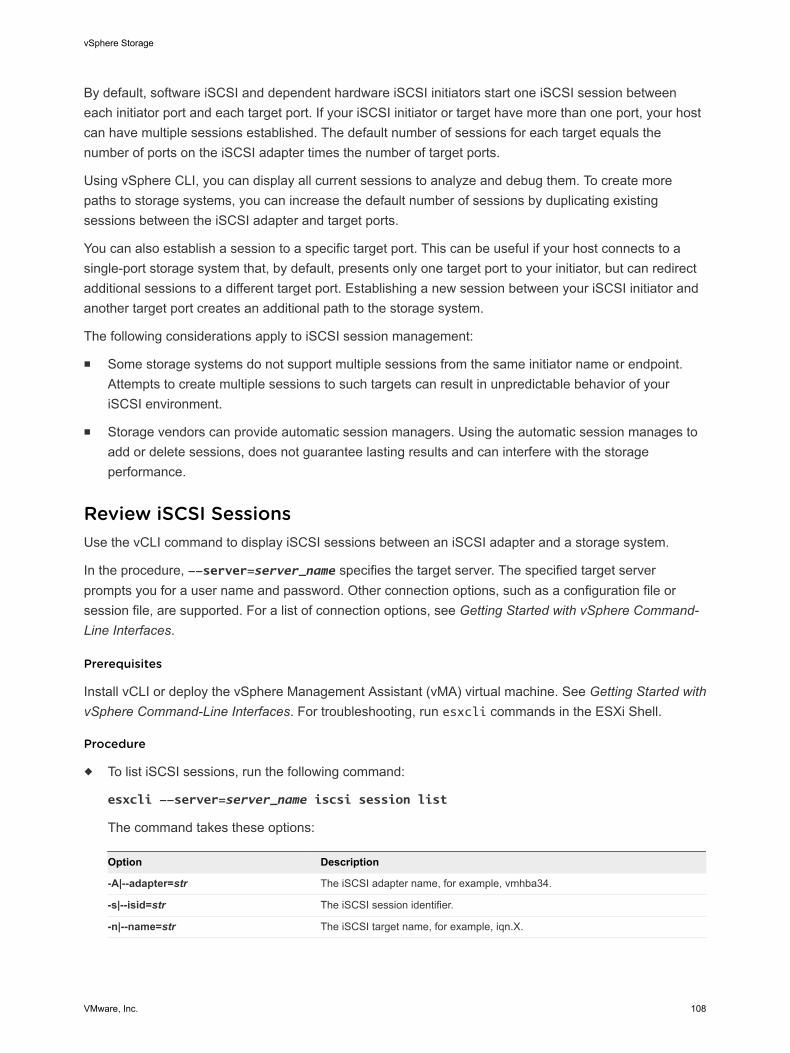
By default, software iSCSI and dependent hardware iSCSI initiators start one iSCSI session betweeneach initiator port and each target port. If your iSCSI initiator or target have more than one port, your hostcan have multiple sessions established. The default number of sessions for each target equals thenumber of ports on the iSCSI adapter times the number of target ports.
Using vSphere CLI, you can display all current sessions to analyze and debug them. To create morepaths to storage systems, you can increase the default number of sessions by duplicating existingsessions between the iSCSI adapter and target ports.
You can also establish a session to a specific target port. This can be useful if your host connects to asingle-port storage system that, by default, presents only one target port to your initiator, but can redirectadditional sessions to a different target port. Establishing a new session between your iSCSI initiator andanother target port creates an additional path to the storage system.
The following considerations apply to iSCSI session management:
n Some storage systems do not support multiple sessions from the same initiator name or endpoint.Attempts to create multiple sessions to such targets can result in unpredictable behavior of youriSCSI environment.
n Storage vendors can provide automatic session managers. Using the automatic session manages toadd or delete sessions, does not guarantee lasting results and can interfere with the storageperformance.
Review iSCSI SessionsUse the vCLI command to display iSCSI sessions between an iSCSI adapter and a storage system.
In the procedure, --server=server_name specifies the target server. The specified target serverprompts you for a user name and password. Other connection options, such as a configuration file orsession file, are supported. For a list of connection options, see Getting Started with vSphere Command-Line Interfaces.
Prerequisites
Install vCLI or deploy the vSphere Management Assistant (vMA) virtual machine. See Getting Started withvSphere Command-Line Interfaces. For troubleshooting, run esxcli commands in the ESXi Shell.
Procedure
u To list iSCSI sessions, run the following command:
esxcli --server=server_name iscsi session list
The command takes these options:
Option Description
-A|--adapter=str The iSCSI adapter name, for example, vmhba34.
-s|--isid=str The iSCSI session identifier.
-n|--name=str The iSCSI target name, for example, iqn.X.
vSphere Storage
VMware, Inc. 108
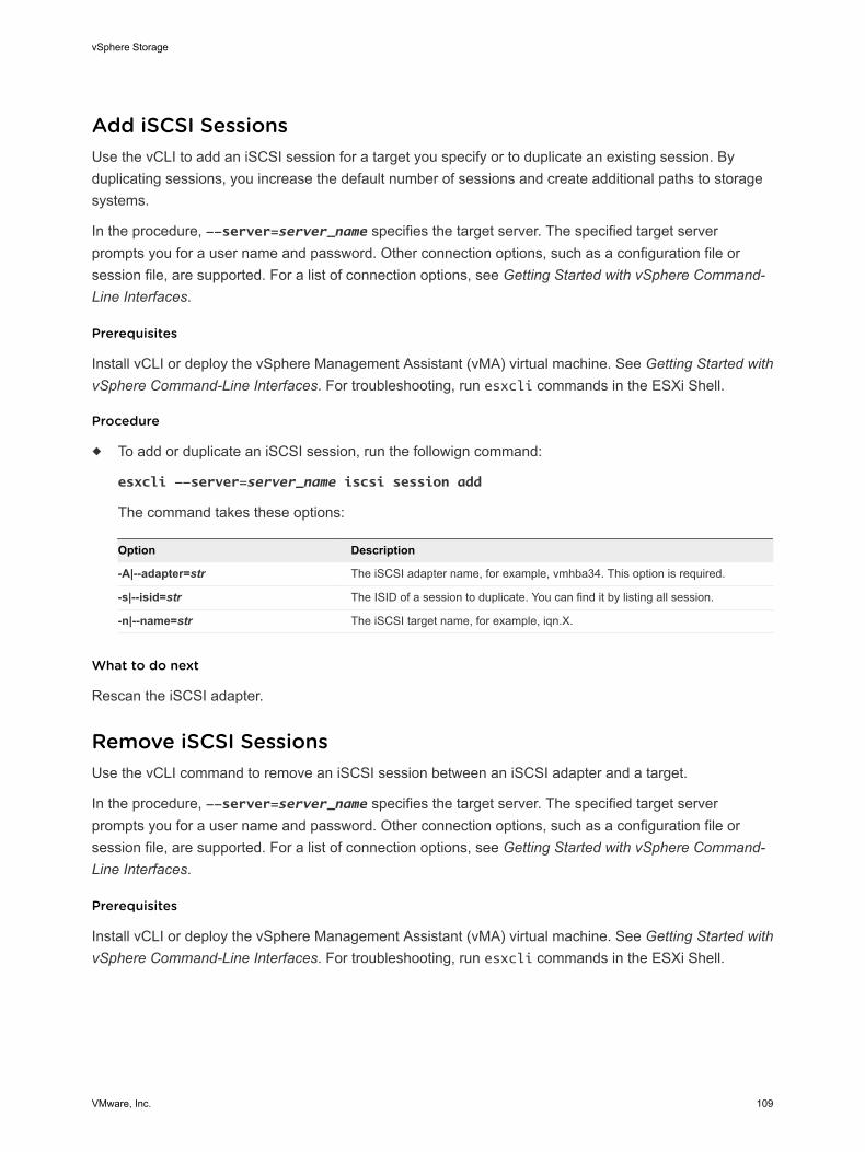
Add iSCSI SessionsUse the vCLI to add an iSCSI session for a target you specify or to duplicate an existing session. Byduplicating sessions, you increase the default number of sessions and create additional paths to storagesystems.
In the procedure, --server=server_name specifies the target server. The specified target serverprompts you for a user name and password. Other connection options, such as a configuration file orsession file, are supported. For a list of connection options, see Getting Started with vSphere Command-Line Interfaces.
Prerequisites
Install vCLI or deploy the vSphere Management Assistant (vMA) virtual machine. See Getting Started withvSphere Command-Line Interfaces. For troubleshooting, run esxcli commands in the ESXi Shell.
Procedure
u To add or duplicate an iSCSI session, run the followign command:
esxcli --server=server_name iscsi session add
The command takes these options:
Option Description
-A|--adapter=str The iSCSI adapter name, for example, vmhba34. This option is required.
-s|--isid=str The ISID of a session to duplicate. You can find it by listing all session.
-n|--name=str The iSCSI target name, for example, iqn.X.
What to do next
Rescan the iSCSI adapter.
Remove iSCSI SessionsUse the vCLI command to remove an iSCSI session between an iSCSI adapter and a target.
In the procedure, --server=server_name specifies the target server. The specified target serverprompts you for a user name and password. Other connection options, such as a configuration file orsession file, are supported. For a list of connection options, see Getting Started with vSphere Command-Line Interfaces.
Prerequisites
Install vCLI or deploy the vSphere Management Assistant (vMA) virtual machine. See Getting Started withvSphere Command-Line Interfaces. For troubleshooting, run esxcli commands in the ESXi Shell.
vSphere Storage
VMware, Inc. 109
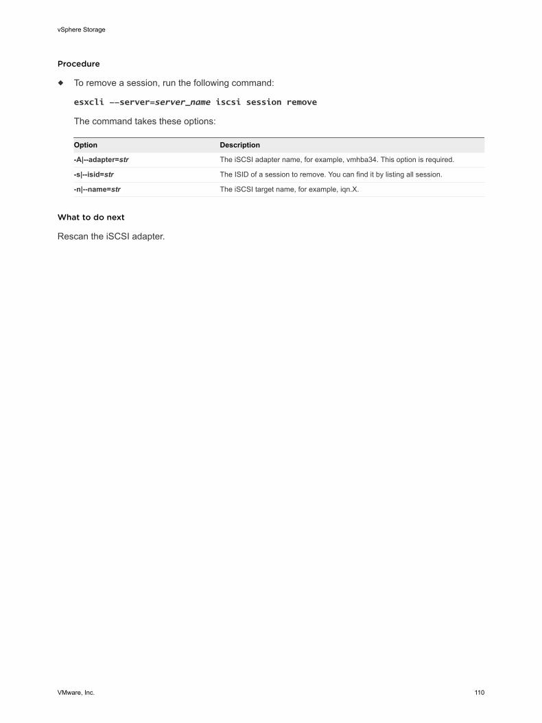
Procedure
u To remove a session, run the following command:
esxcli --server=server_name iscsi session remove
The command takes these options:
Option Description
-A|--adapter=str The iSCSI adapter name, for example, vmhba34. This option is required.
-s|--isid=str The ISID of a session to remove. You can find it by listing all session.
-n|--name=str The iSCSI target name, for example, iqn.X.
What to do next
Rescan the iSCSI adapter.
vSphere Storage
VMware, Inc. 110
Booting from iSCSI SAN 11When you set up your host to boot from a SAN, your host's boot image is stored on one or more LUNs inthe SAN storage system. When the host starts, it boots from the LUN on the SAN rather than from itslocal disk.
You can use boot from the SAN if you do not want to handle maintenance of local storage or havediskless hardware configurations, such as blade systems.
ESXi supports different methods of booting from the iSCSI SAN.
Table 11‑1. Boot from iSCSI SAN support
Independent Hardware iSCSI Software iSCSI and Dependent Hardware iSCSI
Configure the iSCSI HBA to boot from the SAN. Forinformation on configuring the HBA, see ConfigureIndependent Hardware iSCSI Adapter for SAN Boot
Use the network adapter that supports the iBFT. For information, see iBFT iSCSI Boot Overview.
This chapter includes the following topics:
n General Boot from iSCSI SAN Recommendations
n Prepare the iSCSI SAN
n Configure Independent Hardware iSCSI Adapter for SAN Boot
n iBFT iSCSI Boot Overview
General Boot from iSCSI SAN RecommendationsIf you plan to set up and use an iSCSI LUN as the boot device for your host, you need to follow certaingeneral guidelines.
The following guidelines apply to booting from independent hardware iSCSI and iBFT.
n Review any vendor recommendations for the hardware you use in your boot configuration.
n For installation prerequisites and requirements, review vSphere Installation and Setup.
n Use static IP addresses to reduce the chances of DHCP conflicts.
n Use different LUNs for VMFS datastores and boot partitions.
VMware, Inc. 111
n Configure proper ACLs on your storage system.
n The boot LUN should be visible only to the host that uses the LUN. No other host on the SANshould be permitted to see that boot LUN.
n If a LUN is used for a VMFS datastore, it can be shared by multiple hosts. ACLs on the storagesystems can allow you to do this.
n Configure a diagnostic partition.
n With independent hardware iSCSI only, you can place the diagnostic partition on the boot LUN. Ifyou configure the diagnostic partition in the boot LUN, this LUN cannot be shared across multiplehosts. If a separate LUN is used for the diagnostic partition, it can be shared by multiple hosts.
n If you boot from SAN using iBFT, you cannot set up a diagnostic partition on a SAN LUN. Tocollect your host's diagnostic information, use the vSphere ESXi Dump Collector on a remoteserver. For information about the ESXi Dump Collector, see vSphere Installation and Setup andvSphere Networking.
Prepare the iSCSI SANBefore you configure your host to boot from an iSCSI LUN, prepare and configure your storage areanetwork.
Caution If you use scripted installation to install ESXi when booting from a SAN, you must take specialsteps to avoid unintended data loss.
Procedure
1 Connect network cables, referring to any cabling guide that applies to your setup.
2 Ensure IP connectivity between your storage system and server.
This includes proper configuration of any routers or switches on your storage network. Storagesystems must be able to ping the iSCSI adapters in your hosts.
3 Configure the storage system.
a Create a volume (or LUN) on the storage system for your host to boot from.
b Configure the storage system so that your host has access to the assigned LUN.
This could involve updating ACLs with the IP addresses, iSCSI names, and the CHAPauthentication parameter you use on your host. On some storage systems, in addition toproviding access information for the ESXi host, you must also explicitly associate the assignedLUN with the host.
c Ensure that the LUN is presented to the host correctly.
d Ensure that no other system has access to the configured LUN.
e Record the iSCSI name and IP addresses of the targets assigned to the host.
You must have this information to configure your iSCSI adapters.
vSphere Storage
VMware, Inc. 112
Configure Independent Hardware iSCSI Adapter for SANBootIf your ESXi host uses an independent hardware iSCSI adapter, such as QLogic HBA, you need toconfigure the adapter to boot from the SAN.
This procedure discusses how to enable the QLogic iSCSI HBA to boot from the SAN. For moreinformation and more up-to-date details about QLogic adapter configuration settings, see the QLogic website.
Prerequisites
Because you first need to boot from the VMware installation media, set up your host to boot fromCD/DVD-ROM. To achieve this, change the system boot sequence in your system BIOS setup.
Procedure
1 Insert the installation CD/DVD in the CD/DVD-ROM drive and reboot the host.
2 Use the BIOS to set the host to boot from the CD/DVD-ROM drive first.
3 During server POST, press Crtl+q to enter the QLogic iSCSI HBA configuration menu.
4 Select the I/O port to configure.
By default, the Adapter Boot mode is set to Disable.
5 Configure the HBA.
a From the Fast!UTIL Options menu, select Configuration Settings > Host Adapter Settings.
b Configure the following settings for your host adapter: initiator IP address, subnet mask, gateway,initiator iSCSI name, and CHAP (if required).
6 Configure iSCSI settings.
See Configure iSCSI Boot Settings.
7 Save your changes and restart the system.
Configure iSCSI Boot SettingsWhen setting up your ESXi host to boot from iSCSI, you need to configure iSCSI boot settings.
Procedure
1 From the Fast!UTIL Options menu, select Configuration Settings > iSCSI Boot Settings.
2 Before you can set SendTargets, set Adapter Boot mode to Manual.
vSphere Storage
VMware, Inc. 113

3 Select Primary Boot Device Settings.
a Enter the discovery Target IP and Target Port.
b You can leave the Boot LUN and iSCSI Name fields blank if only one iSCSI target and one LUNare at the specified address to boot from. Otherwise, you must specify these fields to ensure thatyou do not boot from a volume for some other system. After the target storage system is reached,these fields will be populated after a rescan.
c Save changes.
4 From the iSCSI Boot Settings menu, select the primary boot device. An auto rescan of the HBA ismade to find new target LUNS.
5 Select the iSCSI target.
Note If more then one LUN exists within the target, you can choose a specific LUN ID by pressingEnter after you locate the iSCSI device.
6 Return to the Primary Boot Device Setting menu. After the rescan, the Boot LUNand iSCSI Namefields are populated. Change the value of Boot LUN to the desired LUN ID.
iBFT iSCSI Boot OverviewESXi hosts can boot from an iSCSI SAN using the software or dependent hardware iSCSI adapters andnetwork adapters.
To deploy ESXi and boot from the iSCSI SAN, the host must have an iSCSI boot capable network adapterthat supports the iSCSI Boot Firmware Table (iBFT) format. The iBFT is a method of communicatingparameters about the iSCSI boot device to an operating system.
Before installing ESXi and booting from the iSCSI SAN, configure the networking and iSCSI bootparameters on the network adapter and enable the adapter for the iSCSI boot. Because configuring thenetwork adapter is vendor specific, review your vendor documentation for instructions.
When you first boot from iSCSI, the iSCSI boot firmware on your system connects to an iSCSI target. Iflogin is successful, the firmware saves the networking and iSCSI boot parameters in the iBFT and storesthe table in the system's memory. The system uses this table to configure its own iSCSI connection andnetworking and to start up.
The following list describes the iBFT iSCSI boot sequence.
1 When restarted, the system BIOS detects the iSCSI boot firmware on the network adapter.
2 The iSCSI boot firmware uses the preconfigured boot parameters to connect with the specified iSCSItarget.
3 If the connection to the iSCSI target is successful, the iSCSI boot firmware writes the networking andiSCSI boot parameters in to the iBFT and stores the table in the system memory.
Note The system uses this table to configure its own iSCSI connection and networking and to startup.
vSphere Storage
VMware, Inc. 114
4 The BIOS boots the boot device.
5 The VMkernel starts loading and takes over the boot operation.
6 Using the boot parameters from the iBFT, the VMkernel connects to the iSCSI target.
7 After the iSCSI connection is established, the system boots.
iBFT iSCSI Boot ConsiderationsWhen you boot the ESXi host from iSCSI using iBFT-enabled network adapters, certain considerationsapply.
n Update your NIC's boot code and iBFT firmware using vendor supplied tools before trying to installand boot VMware ESXi. Consult vendor documentation and VMware HCL for supported boot codeand iBFT firmware versions for VMware ESXi iBFT boot.
n The iBFT iSCSI boot does not support failover for the iBFT-enabled network adapters.
n After you set up your host to boot from iBFT iSCSI, the following restrictions apply:n You cannot disable the software iSCSI adapter. If the iBFT configuration is present in the BIOS,
the host re-enables the software iSCSI adapter during each reboot.
Note If you do not use the iBFT-enabled network adapter for the iSCSI boot and do not want thesoftware iSCSI adapter to be always enabled, remove the iBFT configuration from the networkadapter.
n You cannot remove the iBFT iSCSI boot target using the vSphere Web Client. The target appearson the list of adapter static targets.
Configuring iBFT Boot from SANYou can boot from the iSCSI SAN using the software iSCSI adapter or a dependent hardware iSCSIadapter and a network adapter. The network adapter must support iBFT.
When you set up your host to boot with iBFT, you perform a number of tasks.1 Configure iSCSI Boot Parameters
To begin an iSCSI boot process, a network adapter on your host must have a specially configurediSCSI boot firmware. When you configure the firmware, you specify the networking and iSCSIparameters and enable the adapter for the iSCSI boot.
2 Change Boot Sequence in BIOS
When setting up your host to boot from iBFT iSCSI, change the boot sequence to force your host toboot in an appropriate order.
3 Install ESXi to iSCSI Target
When setting up your host to boot from iBFT iSCSI, install the ESXi image to the target LUN.
4 Boot ESXi from iSCSI Target
After preparing the host for an iBFT iSCSI boot and copying the ESXi image to the iSCSI target,perform the actual boot.
vSphere Storage
VMware, Inc. 115

Configure iSCSI Boot ParametersTo begin an iSCSI boot process, a network adapter on your host must have a specially configured iSCSIboot firmware. When you configure the firmware, you specify the networking and iSCSI parameters andenable the adapter for the iSCSI boot.
Configuration on the network adapter can be dynamic or static. If you use the dynamic configuration, youindicate that all target and initiator boot parameters are acquired using DHCP. For the static configuration,you manually enter data that includes your host's IP address and initiator IQN, and the target parameters.
Procedure
u On the network adapter that you use for the boot from iSCSI, specify networking and iSCSIparameters.
Because configuring the network adapter is vendor specific, review your vendor documentation forinstructions.
Change Boot Sequence in BIOSWhen setting up your host to boot from iBFT iSCSI, change the boot sequence to force your host to bootin an appropriate order.
Change the BIOS boot sequence to the following sequence:
n iSCSI
n DVD-ROM
Because changing the boot sequence in the BIOS is vendor specific, refer to vendor documentation forinstructions. The following sample procedure explains how to change the boot sequence on a Dell hostwith a Broadcom network adapter.
Procedure
1 Turn on the host.
2 During Power-On Self-Test (POST), press F2 to enter the BIOS Setup.
3 In the BIOS Setup, select Boot Sequence and press Enter.
4 In the Boot Sequence menu, arrange the bootable items so that iSCSI precedes the DVD-ROM.
5 Press Esc to exit the Boot Sequence menu.
6 Press Esc to exit the BIOS Setup.
7 Select Save Changes and click Exit to exit the BIOS Setup menu.
Install ESXi to iSCSI TargetWhen setting up your host to boot from iBFT iSCSI, install the ESXi image to the target LUN.
vSphere Storage
VMware, Inc. 116

Prerequisites
n Configure iSCSI boot firmware on your boot NIC to point to the target LUN that you want to use asthe boot LUN.
n Change the boot sequence in the BIOS so that iSCSI precedes the DVD-ROM.
n If you use Broadcom adapters, set Boot to iSCSI target to Disabled.
Procedure
1 Insert the installation media in the CD/DVD-ROM drive and restart the host.
2 When the installer starts, follow the typical installation procedure.
3 When prompted, select the iSCSI LUN as the installation target.
The installer copies the ESXi boot image to the iSCSI LUN.
4 After the system restarts, remove the installation DVD.
Boot ESXi from iSCSI TargetAfter preparing the host for an iBFT iSCSI boot and copying the ESXi image to the iSCSI target, performthe actual boot.
Prerequisites
n Configure the iSCSI boot firmware on your boot NIC to point to the boot LUN.
n Change the boot sequence in the BIOS so that iSCSI precedes the boot device.
n If you use Broadcom adapters, set Boot to iSCSI target to Enabled
Procedure
1 Restart the host.
The host boots from the iSCSI LUN using iBFT data. During the first boot, the iSCSI initializationscript sets up default networking. The network setup is persistent after subsequent reboots.
2 (Optional) Adjust networking configuration using the vSphere Web Client.
Networking Best PracticesTo boot the ESXi host from iSCSI using iBFT, you must properly configure networking.
To achieve greater security and better performance, have redundant network adapters on the host.
How you set up all the network adapters depends on whether your environment uses shared or isolatednetworks for the iSCSI traffic and host management traffic.
Shared iSCSI and Management NetworksConfigure the networking and iSCSI parameters on the first network adapter on the host. After the hostboots, you can add secondary network adapters to the default port group.
vSphere Storage
VMware, Inc. 117
Isolated iSCSI and Management NetworksWhen you configure isolated iSCSI and management networks, follow these guidelines to avoidbandwidth problems.
n Your isolated networks must be on different subnets.
n If you use VLANs to isolate the networks, they must have different subnets to ensure that routingtables are properly set up.
n VMware recommends that you configure the iSCSI adapter and target to be on the same subnet. Ifyou set up the iSCSI adapter and target on different subnets, the following restrictions apply:
n The default VMkernel gateway must be able to route both the management and iSCSI traffic.
n After you boot your host, you can use the iBFT-enabled network adapter only for iBFT. Youcannot use the adapter for other iSCSI traffic.
n Use the first physical network adapter for the management network.
n Use the second physical network adapter for the iSCSI network. Make sure to configure the iBFT.
n After the host boots, you can add secondary network adapters to both the management and iSCSInetworks.
Change iBFT iSCSI Boot SettingsIf settings, such as the IQN name, IP address, and so on, change on the iSCSI storage or your host,update the iBFT. This task assumes that the boot LUN and the data stored on the LUN remain intact.
Procedure
1 Shut down the ESXi host.
2 Change iSCSI storage settings.
3 Update the iBFT on the host with the new settings.
4 Restart the host.
The host boots using the new information stored in the iBFT.
Troubleshooting iBFT iSCSI BootThe topics in this section help you to identify and solve problems you might encounter when using iBFTiSCSI boot.
Loss of System's Gateway Causes Loss of Network ConnectivityYou lose network connectivity when you delete a port group associated with the iBFT network adapter.
Problem
A loss of network connectivity occurs after you delete a port group.
vSphere Storage
VMware, Inc. 118
Cause
When you specify a gateway in the iBFT-enabled network adapter during ESXi installation, this gatewaybecomes the system's default gateway. If you delete the port group associated with the network adapter,the system's default gateway is lost. This action causes the loss of network connectivity.
Solution
Do not set an iBFT gateway unless it is required. If the gateway is required, after installation, manually setthe system's default gateway to the one that the management network uses.
Changing iSCSI Boot Parameters Causes ESXi to Boot in Stateless ModeChanging iSCSI boot parameters on the network adapter after the first boot does not update the iSCSIand networking configuration on the ESXi host.
Problem
If you change the iSCSI boot parameters on the network adapter after the first ESXi boot from iSCSI, thehost will boot in a stateless mode.
Cause
The firmware uses the updated boot configuration and is able to connect to the iSCSI target and load theESXi image. However, when loaded, the system does not pick up the new parameters, but continues touse persistent networking and iSCSI parameters from the previous boot. As a result, the host cannotconnect to the target and boots in the stateless mode.
Solution
1 Use the vSphere Web Client to connect to the ESXi host.
2 Re-configure the iSCSI and networking on the host to match the iBFT parameters.
3 Perform a rescan.
vSphere Storage
VMware, Inc. 119
Best Practices for iSCSI Storage 12When using ESXi with the iSCSI SAN, follow best practices that VMware offers to avoid problems.
Check with your storage representative if your storage system supports Storage API - Array Integrationhardware acceleration features. If it does, refer to your vendor documentation for information on how toenable hardware acceleration support on the storage system side. For more information, see Chapter 23Storage Hardware Acceleration.
This chapter includes the following topics:
n Preventing iSCSI SAN Problems
n Optimizing iSCSI SAN Storage Performance
n Checking Ethernet Switch Statistics
Preventing iSCSI SAN ProblemsWhen using ESXi in conjunction with a SAN, you must follow specific guidelines to avoid SAN problems.
You should observe these tips for avoiding problems with your SAN configuration:
n Place only one VMFS datastore on each LUN. Multiple VMFS datastores on one LUN is notrecommended.
n Do not change the path policy the system sets for you unless you understand the implications ofmaking such a change.
n Document everything. Include information about configuration, access control, storage, switch, serverand iSCSI HBA configuration, software and firmware versions, and storage cable plan.
n Plan for failure:
n Make several copies of your topology maps. For each element, consider what happens to yourSAN if the element fails.
n Cross off different links, switches, HBAs and other elements to ensure you did not miss a criticalfailure point in your design.
n Ensure that the iSCSI HBAs are installed in the correct slots in the ESXi host, based on slot and busspeed. Balance PCI bus load among the available busses in the server.
n Become familiar with the various monitor points in your storage network, at all visibility points,including ESXi performance charts, Ethernet switch statistics, and storage performance statistics.
VMware, Inc. 120
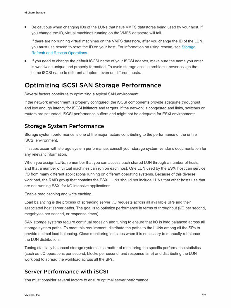
n Be cautious when changing IDs of the LUNs that have VMFS datastores being used by your host. Ifyou change the ID, virtual machines running on the VMFS datastore will fail.
If there are no running virtual machines on the VMFS datastore, after you change the ID of the LUN,you must use rescan to reset the ID on your host. For information on using rescan, see StorageRefresh and Rescan Operations.
n If you need to change the default iSCSI name of your iSCSI adapter, make sure the name you enteris worldwide unique and properly formatted. To avoid storage access problems, never assign thesame iSCSI name to different adapters, even on different hosts.
Optimizing iSCSI SAN Storage PerformanceSeveral factors contribute to optimizing a typical SAN environment.
If the network environment is properly configured, the iSCSI components provide adequate throughputand low enough latency for iSCSI initiators and targets. If the network is congested and links, switches orrouters are saturated, iSCSI performance suffers and might not be adequate for ESXi environments.
Storage System PerformanceStorage system performance is one of the major factors contributing to the performance of the entireiSCSI environment.
If issues occur with storage system performance, consult your storage system vendor’s documentation forany relevant information.
When you assign LUNs, remember that you can access each shared LUN through a number of hosts,and that a number of virtual machines can run on each host. One LUN used by the ESXi host can serviceI/O from many different applications running on different operating systems. Because of this diverseworkload, the RAID group that contains the ESXi LUNs should not include LUNs that other hosts use thatare not running ESXi for I/O intensive applications.
Enable read caching and write caching.
Load balancing is the process of spreading server I/O requests across all available SPs and theirassociated host server paths. The goal is to optimize performance in terms of throughput (I/O per second,megabytes per second, or response times).
SAN storage systems require continual redesign and tuning to ensure that I/O is load balanced across allstorage system paths. To meet this requirement, distribute the paths to the LUNs among all the SPs toprovide optimal load balancing. Close monitoring indicates when it is necessary to manually rebalancethe LUN distribution.
Tuning statically balanced storage systems is a matter of monitoring the specific performance statistics(such as I/O operations per second, blocks per second, and response time) and distributing the LUNworkload to spread the workload across all the SPs.
Server Performance with iSCSIYou must consider several factors to ensure optimal server performance.
vSphere Storage
VMware, Inc. 121

Each server application must have access to its designated storage with the following conditions:
n High I/O rate (number of I/O operations per second)
n High throughput (megabytes per second)
n Minimal latency (response times)
Because each application has different requirements, you can meet these goals by choosing anappropriate RAID group on the storage system. To achieve performance goals, perform the followingtasks:
n Place each LUN on a RAID group that provides the necessary performance levels. Pay attention tothe activities and resource utilization of other LUNS in the assigned RAID group. A high-performanceRAID group that has too many applications doing I/O to it might not meet performance goals requiredby an application running on the ESXi host.
n Provide each server with a sufficient number of network adapters or iSCSI hardware adapters toallow maximum throughput for all the applications hosted on the server for the peak period. I/Ospread across multiple ports provides higher throughput and less latency for each application.
n To provide redundancy for software iSCSI, make sure the initiator is connected to all networkadapters used for iSCSI connectivity.
n When allocating LUNs or RAID groups for ESXi systems, multiple operating systems use and sharethat resource. As a result, the performance required from each LUN in the storage subsystem can bemuch higher if you are working with ESXi systems than if you are using physical machines. Forexample, if you expect to run four I/O intensive applications, allocate four times the performancecapacity for the ESXi LUNs.
n When using multiple ESXi systems in conjunction with vCenter Server, the performance needed fromthe storage subsystem increases correspondingly.
n The number of outstanding I/Os needed by applications running on an ESXi system should match thenumber of I/Os the SAN can handle.
Network PerformanceA typical SAN consists of a collection of computers connected to a collection of storage systems througha network of switches. Several computers often access the same storage.
Single Ethernet Link Connection to Storage shows several computer systems connected to a storagesystem through an Ethernet switch. In this configuration, each system is connected through a singleEthernet link to the switch, which is also connected to the storage system through a single Ethernet link.In most configurations, with modern switches and typical traffic, this is not a problem.
vSphere Storage
VMware, Inc. 122
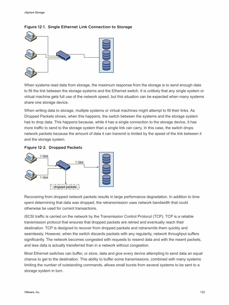
Figure 12‑1. Single Ethernet Link Connection to Storage
When systems read data from storage, the maximum response from the storage is to send enough datato fill the link between the storage systems and the Ethernet switch. It is unlikely that any single system orvirtual machine gets full use of the network speed, but this situation can be expected when many systemsshare one storage device.
When writing data to storage, multiple systems or virtual machines might attempt to fill their links. AsDropped Packets shows, when this happens, the switch between the systems and the storage systemhas to drop data. This happens because, while it has a single connection to the storage device, it hasmore traffic to send to the storage system than a single link can carry. In this case, the switch dropsnetwork packets because the amount of data it can transmit is limited by the speed of the link between itand the storage system.
Figure 12‑2. Dropped Packets
1 Gbit
1 Gbit
1 Gbit
dropped packets
Recovering from dropped network packets results in large performance degradation. In addition to timespent determining that data was dropped, the retransmission uses network bandwidth that couldotherwise be used for current transactions.
iSCSI traffic is carried on the network by the Transmission Control Protocol (TCP). TCP is a reliabletransmission protocol that ensures that dropped packets are retried and eventually reach theirdestination. TCP is designed to recover from dropped packets and retransmits them quickly andseamlessly. However, when the switch discards packets with any regularity, network throughput sufferssignificantly. The network becomes congested with requests to resend data and with the resent packets,and less data is actually transferred than in a network without congestion.
Most Ethernet switches can buffer, or store, data and give every device attempting to send data an equalchance to get to the destination. This ability to buffer some transmissions, combined with many systemslimiting the number of outstanding commands, allows small bursts from several systems to be sent to astorage system in turn.
vSphere Storage
VMware, Inc. 123
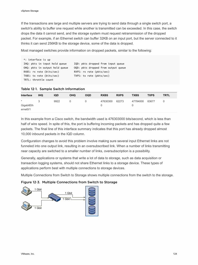
If the transactions are large and multiple servers are trying to send data through a single switch port, aswitch's ability to buffer one request while another is transmitted can be exceeded. In this case, the switchdrops the data it cannot send, and the storage system must request retransmission of the droppedpacket. For example, if an Ethernet switch can buffer 32KB on an input port, but the server connected to itthinks it can send 256KB to the storage device, some of the data is dropped.
Most managed switches provide information on dropped packets, similar to the following:
*: interface is up
IHQ: pkts in input hold queue IQD: pkts dropped from input queue
OHQ: pkts in output hold queue OQD: pkts dropped from output queue
RXBS: rx rate (bits/sec) RXPS: rx rate (pkts/sec)
TXBS: tx rate (bits/sec) TXPS: tx rate (pkts/sec)
TRTL: throttle count
Table 12‑1. Sample Switch Information
Interface IHQ IQD OHQ OQD RXBS RXPS TXBS TXPS TRTL
*GigabitEthernet0/1
3 9922 0 0 476303000
62273 477840000
63677 0
In this example from a Cisco switch, the bandwidth used is 476303000 bits/second, which is less thanhalf of wire speed. In spite of this, the port is buffering incoming packets and has dropped quite a fewpackets. The final line of this interface summary indicates that this port has already dropped almost10,000 inbound packets in the IQD column.
Configuration changes to avoid this problem involve making sure several input Ethernet links are notfunneled into one output link, resulting in an oversubscribed link. When a number of links transmittingnear capacity are switched to a smaller number of links, oversubscription is a possibility.
Generally, applications or systems that write a lot of data to storage, such as data acquisition ortransaction logging systems, should not share Ethernet links to a storage device. These types ofapplications perform best with multiple connections to storage devices.
Multiple Connections from Switch to Storage shows multiple connections from the switch to the storage.
Figure 12‑3. Multiple Connections from Switch to Storage
1 Gbit
1 Gbit
1 Gbit
1 Gbit
vSphere Storage
VMware, Inc. 124
Using VLANs or VPNs does not provide a suitable solution to the problem of link oversubscription inshared configurations. VLANs and other virtual partitioning of a network provide a way of logicallydesigning a network, but do not change the physical capabilities of links and trunks between switches.When storage traffic and other network traffic end up sharing physical connections, as they would with aVPN, the possibility for oversubscription and lost packets exists. The same is true of VLANs that shareinterswitch trunks. Performance design for a SANs must take into account the physical limitations of thenetwork, not logical allocations.
Checking Ethernet Switch StatisticsMany Ethernet switches provide different methods for monitoring switch health.
Switches that have ports operating near maximum throughput much of the time do not provide optimumperformance. If you have ports in your iSCSI SAN running near the maximum, reduce the load. If the portis connected to an ESXi system or iSCSI storage, you can reduce the load by using manual loadbalancing.
If the port is connected between multiple switches or routers, consider installing additional links betweenthese components to handle more load. Ethernet switches also commonly provide information abouttransmission errors, queued packets, and dropped Ethernet packets. If the switch regularly reports any ofthese conditions on ports being used for iSCSI traffic, performance of the iSCSI SAN will be poor.
vSphere Storage
VMware, Inc. 125

Managing Storage Devices 13Manage local and networked storage device that your ESXi host has access to.
This chapter includes the following topics:
n Storage Device Characteristics
n Understanding Storage Device Naming
n Storage Refresh and Rescan Operations
n Identifying Device Connectivity Problems
n Edit Configuration File Parameters
n Enable or Disable the Locator LED on Storage Devices
Storage Device CharacteristicsYou can display all storage devices or LUNs available to the host, including all local and networkeddevices. If you use third-party multipathing plug-ins, the storage devices available through the plug-insalso appear on the list.
For each storage adapter, you can display a separate list of storage devices available for this adapter.
Generally, when you review storage devices, you see the following information.
Table 13‑1. Storage Device Information
Storage Device Information Description
Name Also called Display Name. It is a name that the ESXi host assigns to the device based on thestorage type and manufacturer. You can change this name to a name of your choice.
Identifier A universally unique identifier that is intrinsic to the device.
Operational State Indicates whether the device is mounted or unmounted. For details, see Detach StorageDevices.
LUN Logical Unit Number (LUN) within the SCSI target. The LUN number is provided by the storagesystem. If a target has only one LUN, the LUN number is always zero (0).
Type Type of device, for example, disk or CD-ROM.
Drive Type Information about whether the device is a flash drive or a regular HDD drive. For informationabout flash drives, see Chapter 14 Working with Flash Devices.
VMware, Inc. 126
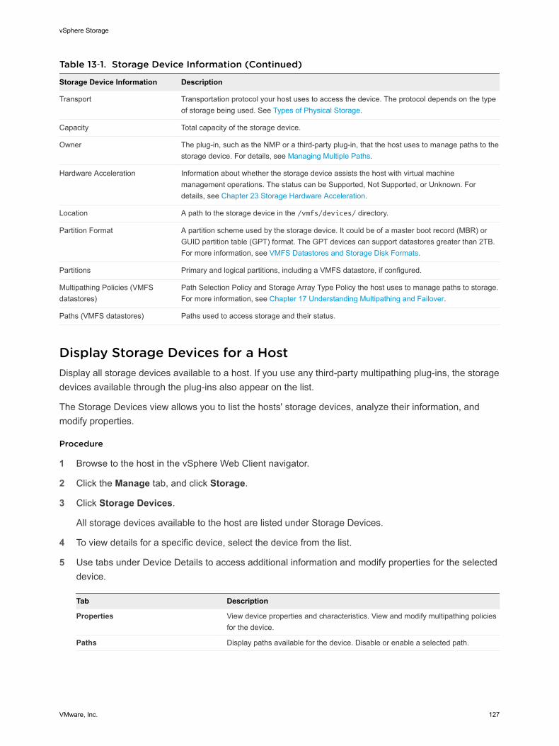
Table 13‑1. Storage Device Information (Continued)
Storage Device Information Description
Transport Transportation protocol your host uses to access the device. The protocol depends on the typeof storage being used. See Types of Physical Storage.
Capacity Total capacity of the storage device.
Owner The plug-in, such as the NMP or a third-party plug-in, that the host uses to manage paths to thestorage device. For details, see Managing Multiple Paths.
Hardware Acceleration Information about whether the storage device assists the host with virtual machinemanagement operations. The status can be Supported, Not Supported, or Unknown. Fordetails, see Chapter 23 Storage Hardware Acceleration.
Location A path to the storage device in the /vmfs/devices/ directory.
Partition Format A partition scheme used by the storage device. It could be of a master boot record (MBR) orGUID partition table (GPT) format. The GPT devices can support datastores greater than 2TB.For more information, see VMFS Datastores and Storage Disk Formats.
Partitions Primary and logical partitions, including a VMFS datastore, if configured.
Multipathing Policies (VMFSdatastores)
Path Selection Policy and Storage Array Type Policy the host uses to manage paths to storage.For more information, see Chapter 17 Understanding Multipathing and Failover.
Paths (VMFS datastores) Paths used to access storage and their status.
Display Storage Devices for a HostDisplay all storage devices available to a host. If you use any third-party multipathing plug-ins, the storagedevices available through the plug-ins also appear on the list.
The Storage Devices view allows you to list the hosts' storage devices, analyze their information, andmodify properties.
Procedure
1 Browse to the host in the vSphere Web Client navigator.
2 Click the Manage tab, and click Storage.
3 Click Storage Devices.
All storage devices available to the host are listed under Storage Devices.
4 To view details for a specific device, select the device from the list.
5 Use tabs under Device Details to access additional information and modify properties for the selecteddevice.
Tab Description
Properties View device properties and characteristics. View and modify multipathing policiesfor the device.
Paths Display paths available for the device. Disable or enable a selected path.
vSphere Storage
VMware, Inc. 127
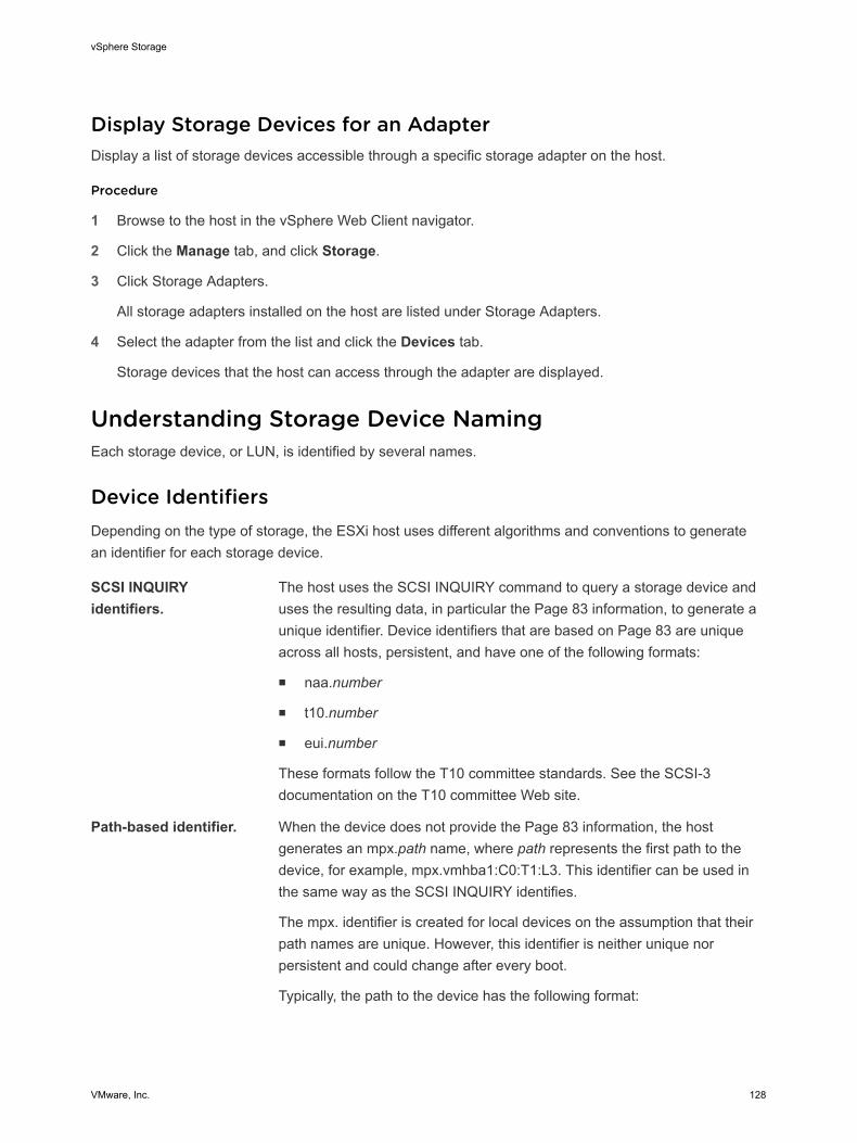
Display Storage Devices for an AdapterDisplay a list of storage devices accessible through a specific storage adapter on the host.
Procedure
1 Browse to the host in the vSphere Web Client navigator.
2 Click the Manage tab, and click Storage.
3 Click Storage Adapters.
All storage adapters installed on the host are listed under Storage Adapters.
4 Select the adapter from the list and click the Devices tab.
Storage devices that the host can access through the adapter are displayed.
Understanding Storage Device NamingEach storage device, or LUN, is identified by several names.
Device IdentifiersDepending on the type of storage, the ESXi host uses different algorithms and conventions to generatean identifier for each storage device.
SCSI INQUIRYidentifiers.
The host uses the SCSI INQUIRY command to query a storage device anduses the resulting data, in particular the Page 83 information, to generate aunique identifier. Device identifiers that are based on Page 83 are uniqueacross all hosts, persistent, and have one of the following formats:
n naa.number
n t10.number
n eui.number
These formats follow the T10 committee standards. See the SCSI-3documentation on the T10 committee Web site.
Path-based identifier. When the device does not provide the Page 83 information, the hostgenerates an mpx.path name, where path represents the first path to thedevice, for example, mpx.vmhba1:C0:T1:L3. This identifier can be used inthe same way as the SCSI INQUIRY identifies.
The mpx. identifier is created for local devices on the assumption that theirpath names are unique. However, this identifier is neither unique norpersistent and could change after every boot.
Typically, the path to the device has the following format:
vSphere Storage
VMware, Inc. 128
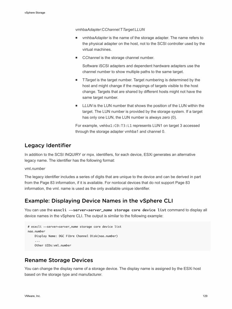
vmhbaAdapter:CChannel:TTarget:LLUN
n vmhbaAdapter is the name of the storage adapter. The name refers tothe physical adapter on the host, not to the SCSI controller used by thevirtual machines.
n CChannel is the storage channel number.
Software iSCSI adapters and dependent hardware adapters use thechannel number to show multiple paths to the same target.
n TTarget is the target number. Target numbering is determined by thehost and might change if the mappings of targets visible to the hostchange. Targets that are shared by different hosts might not have thesame target number.
n LLUN is the LUN number that shows the position of the LUN within thetarget. The LUN number is provided by the storage system. If a targethas only one LUN, the LUN number is always zero (0).
For example, vmhba1:C0:T3:L1 represents LUN1 on target 3 accessedthrough the storage adapter vmhba1 and channel 0.
Legacy IdentifierIn addition to the SCSI INQUIRY or mpx. identifiers, for each device, ESXi generates an alternativelegacy name. The identifier has the following format:
vml.number
The legacy identifier includes a series of digits that are unique to the device and can be derived in partfrom the Page 83 information, if it is available. For nonlocal devices that do not support Page 83information, the vml. name is used as the only available unique identifier.
Example: Displaying Device Names in the vSphere CLIYou can use the esxcli --server=server_name storage core device list command to display alldevice names in the vSphere CLI. The output is similar to the following example:
# esxcli --server=server_name storage core device list
naa.number
Display Name: DGC Fibre Channel Disk(naa.number)
...
Other UIDs:vml.number
Rename Storage DevicesYou can change the display name of a storage device. The display name is assigned by the ESXi hostbased on the storage type and manufacturer.
vSphere Storage
VMware, Inc. 129
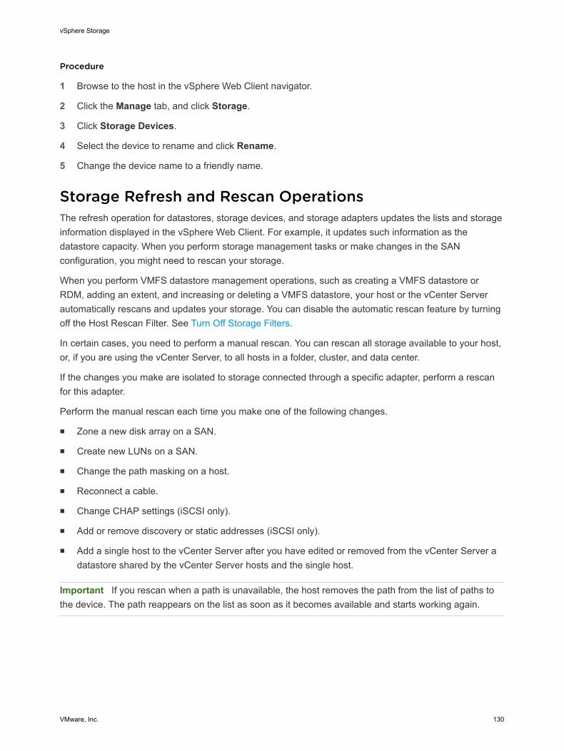
Procedure
1 Browse to the host in the vSphere Web Client navigator.
2 Click the Manage tab, and click Storage.
3 Click Storage Devices.
4 Select the device to rename and click Rename.
5 Change the device name to a friendly name.
Storage Refresh and Rescan OperationsThe refresh operation for datastores, storage devices, and storage adapters updates the lists and storageinformation displayed in the vSphere Web Client. For example, it updates such information as thedatastore capacity. When you perform storage management tasks or make changes in the SANconfiguration, you might need to rescan your storage.
When you perform VMFS datastore management operations, such as creating a VMFS datastore orRDM, adding an extent, and increasing or deleting a VMFS datastore, your host or the vCenter Serverautomatically rescans and updates your storage. You can disable the automatic rescan feature by turningoff the Host Rescan Filter. See Turn Off Storage Filters.
In certain cases, you need to perform a manual rescan. You can rescan all storage available to your host,or, if you are using the vCenter Server, to all hosts in a folder, cluster, and data center.
If the changes you make are isolated to storage connected through a specific adapter, perform a rescanfor this adapter.
Perform the manual rescan each time you make one of the following changes.
n Zone a new disk array on a SAN.
n Create new LUNs on a SAN.
n Change the path masking on a host.
n Reconnect a cable.
n Change CHAP settings (iSCSI only).
n Add or remove discovery or static addresses (iSCSI only).
n Add a single host to the vCenter Server after you have edited or removed from the vCenter Server adatastore shared by the vCenter Server hosts and the single host.
Important If you rescan when a path is unavailable, the host removes the path from the list of paths tothe device. The path reappears on the list as soon as it becomes available and starts working again.
vSphere Storage
VMware, Inc. 130

Perform Storage RescanWhen you make changes in your SAN configuration, you might need to rescan your storage. You canrescan all storage available to your host, cluster, or data center. If the changes you make are isolated tostorage accessed through a specific host, perform rescan for only this host.
Procedure
1 In the vSphere Web Client object navigator, browse to a host, a cluster, a data center, or a folder thatcontains hosts.
2 Select Storage > Rescan Storage from the right-click menu.
3 Specify extent of rescan.
Option Description
Scan for New Storage Devices Rescan all adapters to discover new storage devices. If new devices arediscovered, they appear in the device list.
Scan for New VMFS Volumes Rescan all storage devices to discover new datastores that have been addedsince the last scan. Any new datastores appear in the datastore list.
Perform Adapter RescanWhen you make changes in your SAN configuration and these changes are isolated to storage accessedthrough a specific adapter, perform rescan for only this adapter.
Procedure
1 Browse to the host in the vSphere Web Client navigator.
2 Click the Manage tab, and click Storage.
3 Click Storage Adapters, and select the adapter to rescan from the list.
4 Click the Rescan Adapter icon.
Change the Number of Scanned Storage DevicesWhile an ESXi host is limited to accessing 256 SCSI storage devices, the range of LUN IDs can be from 0to 1023. ESXi ignores LUN IDs 1024 or greater. This limit is controlled by Disk.MaxLUN, which has adefault value of 1024.
The value of Disk.MaxLUN also determines how many LUNs the SCSI scan code attempts to discoverusing individual INQUIRY commands if the SCSI target does not support direct discovery usingREPORT_LUNS.
You can modify the Disk.MaxLUN parameter depending on your needs. For example, if your environmenthas a smaller number of storage devices with LUN IDs from 0 through 100, you can set the value to 101to improve device discovery speed on targets that do not support REPORT_LUNS. Lowering the valuecan shorten the rescan time and boot time. However, the time to rescan storage devices might depend onother factors, including the type of storage system and the load on the storage system.
vSphere Storage
VMware, Inc. 131
In other cases, you might need to increase the value if your environment uses LUN IDs that are greaterthan 1023.
Procedure
1 Browse to the host in the vSphere Web Client navigator.
2 Click the Manage tab, and click Settings.
3 Under System, click Advanced System Settings.
4 Under Advanced System Settings, select Disk.MaxLUN and click the Edit icon.
5 Change the existing value to the value of your choice, and click OK.
The value you enter specifies the LUN ID that is after the last one you want to discover.
For example, to discover LUN IDs from 0 through 100, set Disk.MaxLUN to 101.
Identifying Device Connectivity ProblemsWhen your ESXi host experiences a problem while connecting to a storage device, the host treats theproblem as permanent or temporary depending on certain factors.
Storage connectivity problems are caused by a variety of reasons. Although ESXi cannot alwaysdetermine the reason for a storage device or its paths being unavailable, the host differentiates between apermanent device loss (PDL) state of the device and a transient all paths down (APD) state of storage.
Permanent Device Loss(PDL)
A condition that occurs when a storage device permanently fails or isadministratively removed or excluded. It is not expected to becomeavailable. When the device becomes permanently unavailable, ESXireceives appropriate sense codes or a login rejection from storage arrays,and is able to recognize that the device is permanently lost.
All Paths Down (APD) A condition that occurs when a storage device becomes inaccessible to thehost and no paths to the device are available. ESXi treats this as atransient condition because typically the problems with the device aretemporary and the device is expected to become available again.
Detecting PDL ConditionsA storage device is considered to be in the permanent device loss (PDL) state when it becomespermanently unavailable to your ESXi host.
Typically, the PDL condition occurs when a device is unintentionally removed, or its unique ID changes, orwhen the device experiences an unrecoverable hardware error.
When the storage array determines that the device is permanently unavailable, it sends SCSI sensecodes to the ESXi host. The sense codes allow your host to recognize that the device has failed andregister the state of the device as PDL. The sense codes must be received on all paths to the device forthe device to be considered permanently lost.
vSphere Storage
VMware, Inc. 132
After registering the PDL state of the device, the host stops attempts to reestablish connectivity or toissue commands to the device to avoid becoming blocked or unresponsive.
The vSphere Web Client displays the following information for the device:
n The operational state of the device changes to Lost Communication.
n All paths are shown as Dead.
n Datastores on the device are grayed out.
The host automatically removes the PDL device and all paths to the device if no open connections to thedevice exist, or after the last connection closes. You can disable the automatic removal of paths by settingthe advanced host parameter Disk.AutoremoveOnPDL to 0. See Set Advanced Host Attributes.
If the device returns from the PDL condition, the host can discover it, but treats it as a new device. Dataconsistency for virtual machines on the recovered device is not guaranteed.
Note The host cannot detect PDL conditions and continues to treat the device connectivity problems asAPD when a storage device permanently fails in a way that does not return appropriate SCSI sensecodes or iSCSI login rejection.
Permanent Device Loss and SCSI Sense CodesThe following VMkernel log example of a SCSI sense code indicates that the device is in the PDL state.
H:0x0 D:0x2 P:0x0 Valid sense data: 0x5 0x25 0x0 or Logical Unit Not Supported
For information about SCSI sense codes, see Troubleshooting Storage in vSphere Troubleshooting.
Permanent Device Loss and iSCSIIn the case of iSCSI arrays with a single LUN per target, PDL is detected through iSCSI login failure. AniSCSI storage array rejects your host's attempts to start an iSCSI session with a reason TargetUnavailable. As with the sense codes, this response must be received on all paths for the device to beconsidered permanently lost.
Permanent Device Loss and Virtual MachinesAfter registering the PDL state of the device, the host terminates all I/O from virtual machines. vSphereHA can detect PDL and restart failed virtual machines. For more information, see Device ConnectivityProblems and High Availability.
Performing Planned Storage Device RemovalWhen a storage device is malfunctioning, you can avoid permanent device loss (PDL) conditions or allpaths down (APD) conditions and perform a planned removal and reconnection of a storage device.
vSphere Storage
VMware, Inc. 133
Planned device removal is an intentional disconnection of a storage device. You might also plan toremove a device for such reasons as upgrading your hardware or reconfiguring your storage devices.When you perform an orderly removal and reconnection of a storage device, you complete a number oftasks.
1 Migrate virtual machines from the device you plan to detach.
See the vCenter Server and Host Management documentation.
2 Unmount the datastore deployed on the device.
See Unmount Datastores.
3 Detach the storage device.
See Detach Storage Devices.
4 For an iSCSI device with a single LUN per target, delete the static target entry from each iSCSI HBAthat has a path to the storage device.
See Remove Dynamic or Static iSCSI Targets.
5 Perform any necessary reconfiguration of the storage device by using the array console.
6 Reattach the storage device.
See Attach Storage Devices.
7 Mount the datastore and restart the virtual machines. See Mount Datastores.
Detach Storage DevicesSafely detach a storage device from your host.
You might need to detach the device to make it inaccessible to your host, when, for example, you performa hardware upgrade on the storage side.
Prerequisites
n The device does not contain any datastores.
n No virtual machines use the device as an RDM disk.
n The device does not contain a diagnostic partition or a scratch partition.
Procedure
1 In the vSphere Web Client, display storage devices.
2 Select the device to detach and click the Detach icon.
The device becomes inaccessible. The operational state of the device changes to Unmounted.
What to do next
If multiple hosts share the device, detach the device from each host.
vSphere Storage
VMware, Inc. 134
Attach Storage DevicesReattach a storage device that you previously detached.
Procedure
1 In the vSphere Web Client, display storage devices.
2 Select the detached storage device and click the Attach icon.
The device becomes accessible.
Recovering From PDL ConditionsAn unplanned permanent device loss (PDL) condition occurs when a storage device becomespermanently unavailable without being properly detached from the ESXi host.
The following items in the vSphere Web Client indicate that the device is in the PDL state:
n The datastore deployed on the device is unavailable.
n Operational state of the device changes to Lost Communication.
n All paths are shown as Dead.
n A warning about the device being permanently inaccessible appears in the VMkernel log file.
To recover from the unplanned PDL condition and remove the unavailable device from the host, you needto perform a number of tasks.
1 Power off and unregister all virtual machines that are running on the datastore affected by the PDLcondition.
2 Unmount the datastore.
See Unmount Datastores.
3 Perform a rescan on all ESXi hosts that had access to the device.
See Perform Storage Rescan.
Note If the rescan is not successful and the host continues to list the device, some pending I/O or activereferences to the device might still exist. Check for virtual machines, templates, ISO images, raw devicemappings, and so on that might still have an active reference to the device or datastore.
Handling Transient APD ConditionsA storage device is considered to be in the all paths down (APD) state when it becomes unavailable toyour ESXi host for an unspecified period of time.
The reasons for an APD state can be, for example, a failed switch or a disconnected storage cable.
In contrast with the permanent device loss (PDL) state, the host treats the APD state as transient andexpects the device to be available again.
vSphere Storage
VMware, Inc. 135
The host indefinitely continues to retry issued commands in an attempt to reestablish connectivity with thedevice. If the host's commands fail the retries for a prolonged period of time, the host and its virtualmachines might be at risk of having performance problems and potentially becoming unresponsive.
To avoid these problems, your host uses a default APD handling feature. When a device enters the APDstate, the system immediately turns on a timer and allows your host to continue retrying nonvirtualmachine commands for a limited time period.
By default, the APD timeout is set to 140 seconds, which is typically longer than most devices need torecover from a connection loss. If the device becomes available within this time, the host and its virtualmachine continue to run without experiencing any problems.
If the device does not recover and the timeout ends, the host stops its attempts at retries and terminatesany nonvirtual machine I/O. Virtual machine I/O will continue retrying. The vSphere Web Client displaysthe following information for the device with the expired APD timeout:
n The operational state of the device changes to Dead or Error.
n All paths are shown as Dead.
n Datastores on the device are dimmed.
Even though the device and datastores are unavailable, virtual machines remain responsive. You canpower off the virtual machines or migrate them to a different datastore or host.
If later one or more device paths becomes operational, subsequent I/O to the device is issued normallyand all special APD treatment ends.
Disable Storage APD HandlingThe storage all paths down (APD) handling on your ESXi host is enabled by default. When it is enabled,the host continues to retry nonvirtual machine I/O commands to a storage device in the APD state for alimited time period. When the time period expires, the host stops its retry attempts and terminates anynonvirtual machine I/O. You can disable the APD handling feature on your host.
If you disable the APD handling, the host will indefinitely continue to retry issued commands in an attemptto reconnect to the APD device. Continuing to retry is the same behavior as in ESXi version 5.0. Thisbehavior might cause virtual machines on the host to exceed their internal I/O timeout and becomeunresponsive or fail. The host might become disconnected from vCenter Server.
Procedure
1 Browse to the host in the vSphere Web Client navigator.
2 Click the Manage tab, and click Settings.
3 Under System, click Advanced System Settings.
4 Under Advanced System Settings, select the Misc.APDHandlingEnable parameter and click theEdit icon.
5 Change the value to 0.
vSphere Storage
VMware, Inc. 136
If you disabled the APD handling, you can reenable it when a device enters the APD state. The internalAPD handling feature turns on immediately and the timer starts with the current timeout value for eachdevice in APD.
Change Timeout Limits for Storage APDThe timeout parameter controls how many seconds the ESXi host will retry nonvirtual machine I/Ocommands to a storage device in an all paths down (APD) state. If needed, you can change the defaulttimeout value.
The timer starts immediately after the device enters the APD state. When the timeout expires, the hostmarks the APD device as unreachable and fails any pending or new nonvirtual machine I/O. Virtualmachine I/O will continue to be retried.
The default timeout parameter on your host is 140 seconds. You can increase the value of the timeout if,for example, storage devices connected to your ESXi host take longer than 140 seconds to recover froma connection loss.
Note If you change the timeout value while an APD is in progress, it will not effect the timeout for thatAPD.
Procedure
1 Browse to the host in the vSphere Web Client navigator.
2 Click the Manage tab, and click Settings.
3 Under System, click Advanced System Settings.
4 Under Advanced System Settings, select the Misc.APDTimeout parameter and click the Edit icon.
5 Change the default value.
You can enter a value between 20 and 99999 seconds.
Check the Connection Status of a Storage DeviceUse the esxcli command to verify the connection status of a particular storage device.
In the procedure, --server=server_name specifies the target server. The specified target serverprompts you for a user name and password. Other connection options, such as a configuration file orsession file, are supported. For a list of connection options, see Getting Started with vSphere Command-Line Interfaces.
Prerequisites
Install vCLI or deploy the vSphere Management Assistant (vMA) virtual machine. See Getting Started withvSphere Command-Line Interfaces. For troubleshooting, run esxcli commands in the ESXi Shell.
Procedure
1 Run the esxcli --server=server_name storage core device list -d=device_ID command.
vSphere Storage
VMware, Inc. 137
2 Check the connection status in the Status: field.
n on - Device is connected.
n dead - Device has entered the APD state. The APD timer starts.
n dead timeout - The APD timeout has expired.
n not connected - Device is in the PDL state.
Device Connectivity Problems and High AvailabilityWhen a device enters a Permanent Device Loss (PDL) or an All Paths Down (APD) state, vSphere HighAvailability (HA) can detect connectivity problems and provide automated recovery for affected virtualmachines.
vSphere HA uses VM Component Protection (VMCP) to protect virtual machines running on a host in avSphere HA cluster against accessibility failures. For more information about VMCP and how to configureresponses for datastores and virtual machines when an APD or PDL condition occurs, see the vSphereAvailability documentation.
Edit Configuration File ParametersYou can change or add virtual machine configuration parameters when instructed by a VMware technicalsupport representative, or if you see VMware documentation that instructs you to add or change aparameter to fix a problem with your system.
Important Changing or adding parameters when a system does not have problems might lead todecreased system performance and instability.
The following conditions apply:
n To change a parameter, you change the existing value for the keyword/value pair. For example, if youstart with the keyword/value pair, keyword/value, and change it to keyword/value2, the result iskeyword=value2.
n You cannot delete a configuration parameter entry.
Caution You must assign a value to configuration parameter keywords. If you do not assign a value, thekeyword can return a value of 0, false, or disable, which can result in a virtual machine that cannot poweron.
Procedure
1 Right-click a virtual machine in the inventory and select Edit Settings.
2 Click the VM Options tab and expand Advanced.
3 Click Edit Configuration.
4 (Optional) To add a parameter, click Add Row and type a name and value for the parameter.
5 (Optional) To change a parameter, type a new value in the Value text box for that parameter.
vSphere Storage
VMware, Inc. 138
6 Click OK.
Enable or Disable the Locator LED on Storage DevicesUse the locator LED to identify specific storage devices, so that you can locate them among otherdevices. You can turn the locator LED on or off.
Procedure
1 Browse to the host in the vSphere Web Client navigator.
2 Click the Manage tab, and click Storage.
3 Click Storage Devices.
4 From the list of storage devices, select one or more disks and enable or disable the locator LEDindicator.
Option Description
Enable Click the Turns on the locator LED icon.
Disable Click the Turns off the locator LED icon.
vSphere Storage
VMware, Inc. 139
Working with Flash Devices 14In addition to regular storage hard disk drives (HDDs), vSphere supports flash storage devices.
Unlike the regular HDDs that are electromechanical devices containing moving parts, flash devices usesemiconductors as their storage medium and have no moving parts. Typically, flash devices are veryresilient and provide faster access to data.
To detect flash devices, ESXi uses an inquiry mechanism based on T10 standards. The ESXi host candetect flash devices on a number of storage arrays. Check with your vendor whether your storage arraysupports the ESXi mechanism of flash device detection.
After the host detects the flash devices, you can use them for a variety of tasks and functionalities.
This chapter includes the following topics:n Using Flash Devices with vSphere
n Marking Storage Devices
n Monitor Flash Devices
n Best Practices for Flash Devices
n About Virtual Flash Resource
n Configuring Host Swap Cache
Using Flash Devices with vSphereIn your vSphere environment, you can use flash devices for a variety of functionalities.
VMware, Inc. 140
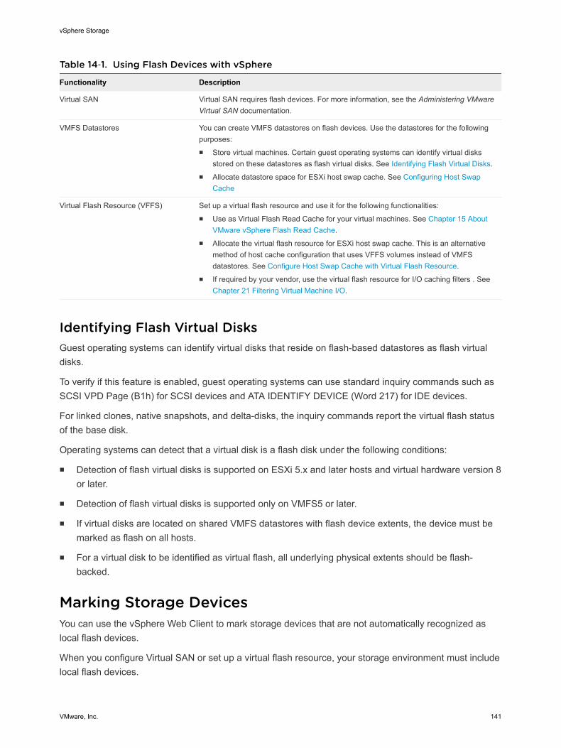
Table 14‑1. Using Flash Devices with vSphere
Functionality Description
Virtual SAN Virtual SAN requires flash devices. For more information, see the Administering VMwareVirtual SAN documentation.
VMFS Datastores You can create VMFS datastores on flash devices. Use the datastores for the followingpurposes:n Store virtual machines. Certain guest operating systems can identify virtual disks
stored on these datastores as flash virtual disks. See Identifying Flash Virtual Disks.n Allocate datastore space for ESXi host swap cache. See Configuring Host Swap
Cache
Virtual Flash Resource (VFFS) Set up a virtual flash resource and use it for the following functionalities:n Use as Virtual Flash Read Cache for your virtual machines. See Chapter 15 About
VMware vSphere Flash Read Cache.n Allocate the virtual flash resource for ESXi host swap cache. This is an alternative
method of host cache configuration that uses VFFS volumes instead of VMFSdatastores. See Configure Host Swap Cache with Virtual Flash Resource.
n If required by your vendor, use the virtual flash resource for I/O caching filters . See Chapter 21 Filtering Virtual Machine I/O.
Identifying Flash Virtual DisksGuest operating systems can identify virtual disks that reside on flash-based datastores as flash virtualdisks.
To verify if this feature is enabled, guest operating systems can use standard inquiry commands such asSCSI VPD Page (B1h) for SCSI devices and ATA IDENTIFY DEVICE (Word 217) for IDE devices.
For linked clones, native snapshots, and delta-disks, the inquiry commands report the virtual flash statusof the base disk.
Operating systems can detect that a virtual disk is a flash disk under the following conditions:
n Detection of flash virtual disks is supported on ESXi 5.x and later hosts and virtual hardware version 8or later.
n Detection of flash virtual disks is supported only on VMFS5 or later.
n If virtual disks are located on shared VMFS datastores with flash device extents, the device must bemarked as flash on all hosts.
n For a virtual disk to be identified as virtual flash, all underlying physical extents should be flash-backed.
Marking Storage DevicesYou can use the vSphere Web Client to mark storage devices that are not automatically recognized aslocal flash devices.
When you configure Virtual SAN or set up a virtual flash resource, your storage environment must includelocal flash devices.
vSphere Storage
VMware, Inc. 141
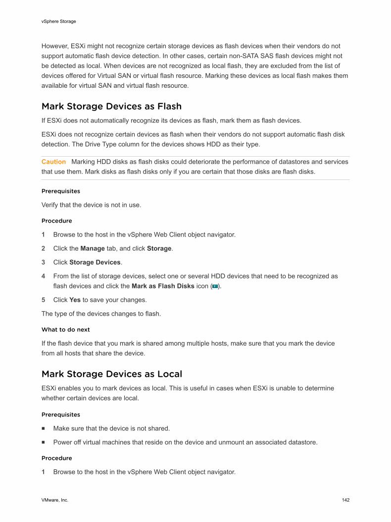
However, ESXi might not recognize certain storage devices as flash devices when their vendors do notsupport automatic flash device detection. In other cases, certain non-SATA SAS flash devices might notbe detected as local. When devices are not recognized as local flash, they are excluded from the list ofdevices offered for Virtual SAN or virtual flash resource. Marking these devices as local flash makes themavailable for virtual SAN and virtual flash resource.
Mark Storage Devices as FlashIf ESXi does not automatically recognize its devices as flash, mark them as flash devices.
ESXi does not recognize certain devices as flash when their vendors do not support automatic flash diskdetection. The Drive Type column for the devices shows HDD as their type.
Caution Marking HDD disks as flash disks could deteriorate the performance of datastores and servicesthat use them. Mark disks as flash disks only if you are certain that those disks are flash disks.
Prerequisites
Verify that the device is not in use.
Procedure
1 Browse to the host in the vSphere Web Client object navigator.
2 Click the Manage tab, and click Storage.
3 Click Storage Devices.
4 From the list of storage devices, select one or several HDD devices that need to be recognized asflash devices and click the Mark as Flash Disks icon ( ).
5 Click Yes to save your changes.
The type of the devices changes to flash.
What to do next
If the flash device that you mark is shared among multiple hosts, make sure that you mark the devicefrom all hosts that share the device.
Mark Storage Devices as LocalESXi enables you to mark devices as local. This is useful in cases when ESXi is unable to determinewhether certain devices are local.
Prerequisites
n Make sure that the device is not shared.
n Power off virtual machines that reside on the device and unmount an associated datastore.
Procedure
1 Browse to the host in the vSphere Web Client object navigator.
vSphere Storage
VMware, Inc. 142
2 Click the Manage tab, and click Storage.
3 Click Storage Devices.
4 From the list of storage devices, select one or several remote devices that need to be marked as localand click the Mark as Local for the Host icon.
5 Click Yes to save your changes.
Monitor Flash DevicesYou can monitor certain critical flash device parameters, including Media Wearout Indicator, Temperature,and Reallocated Sector Count, from an ESXi host.
Use the esxcli command to monitor flash devices.
In the procedure, --server=server_name specifies the target server. The specified target serverprompts you for a user name and password. Other connection options, such as a configuration file orsession file, are supported. For a list of connection options, see Getting Started with vSphere Command-Line Interfaces.
Prerequisites
Install vCLI or deploy the vSphere Management Assistant (vMA) virtual machine. See Getting Started withvSphere Command-Line Interfaces. For troubleshooting, run esxcli commands in the ESXi Shell.
Procedure
u Run the following command to display the flash device statistics:
esxcli server=server_name storage core device smart get -d=flash device_ID
Best Practices for Flash DevicesFollow these best practices when you use flash devices in vSphere environment.
n Make sure to use the latest firmware with flash devices. Frequently check with your storage vendorsfor any updates.
n Carefully monitor how intensively you use the flash device and calculate its estimated lifetime. Thelifetime expectancy depends on how actively you continue to use the flash device.
Estimate Lifetime of Flash DevicesWhen working with flash devices, monitor how actively you use them and calculate their estimatedlifetime.
Typically, storage vendors provide reliable lifetime estimates for a flash device under ideal conditions. Forexample, a vendor might guarantee a lifetime of 5 years under the condition of 20 GB writes per day.However, the more realistic life expectancy of the device depends on how many writes per day your ESXihost actually generates. Follow these steps to calculate the lifetime of the flash device.
vSphere Storage
VMware, Inc. 143
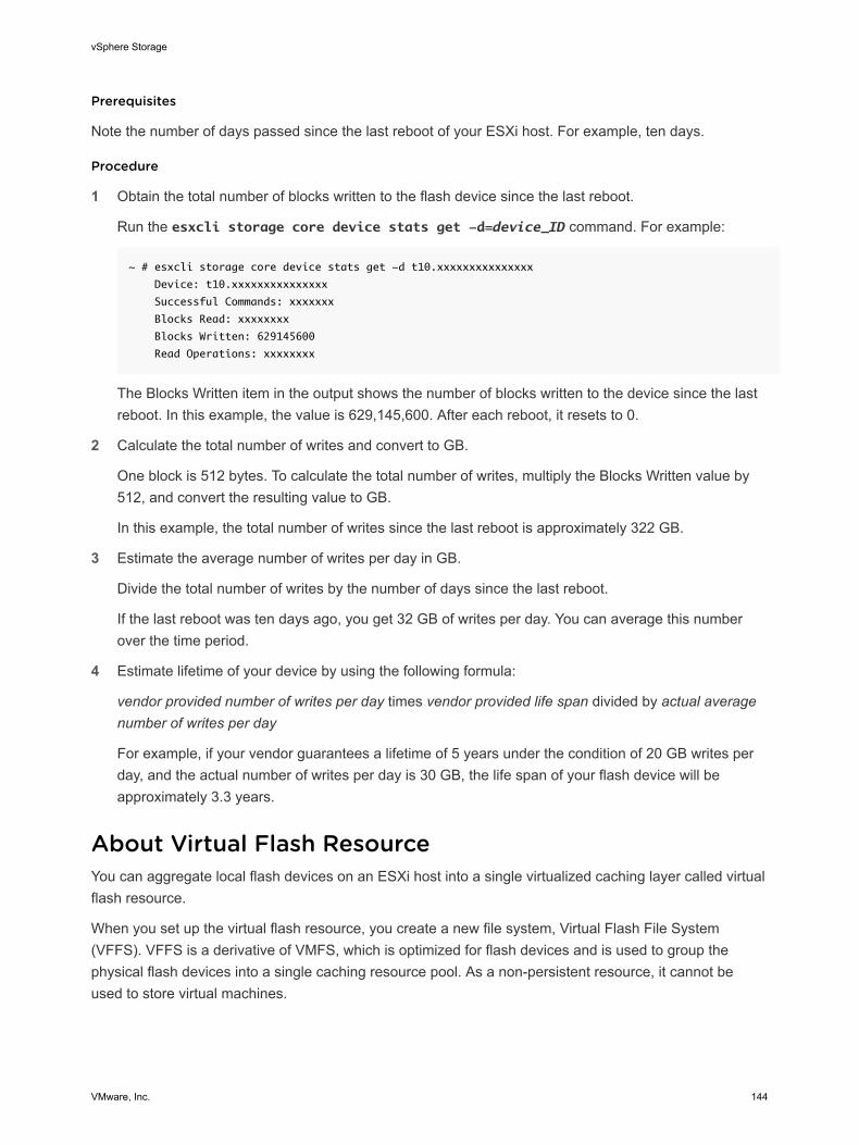
Prerequisites
Note the number of days passed since the last reboot of your ESXi host. For example, ten days.
Procedure
1 Obtain the total number of blocks written to the flash device since the last reboot.
Run the esxcli storage core device stats get -d=device_ID command. For example:
~ # esxcli storage core device stats get -d t10.xxxxxxxxxxxxxxx
Device: t10.xxxxxxxxxxxxxxx
Successful Commands: xxxxxxx
Blocks Read: xxxxxxxx
Blocks Written: 629145600
Read Operations: xxxxxxxx
The Blocks Written item in the output shows the number of blocks written to the device since the lastreboot. In this example, the value is 629,145,600. After each reboot, it resets to 0.
2 Calculate the total number of writes and convert to GB.
One block is 512 bytes. To calculate the total number of writes, multiply the Blocks Written value by512, and convert the resulting value to GB.
In this example, the total number of writes since the last reboot is approximately 322 GB.
3 Estimate the average number of writes per day in GB.
Divide the total number of writes by the number of days since the last reboot.
If the last reboot was ten days ago, you get 32 GB of writes per day. You can average this numberover the time period.
4 Estimate lifetime of your device by using the following formula:
vendor provided number of writes per day times vendor provided life span divided by actual averagenumber of writes per day
For example, if your vendor guarantees a lifetime of 5 years under the condition of 20 GB writes perday, and the actual number of writes per day is 30 GB, the life span of your flash device will beapproximately 3.3 years.
About Virtual Flash ResourceYou can aggregate local flash devices on an ESXi host into a single virtualized caching layer called virtualflash resource.
When you set up the virtual flash resource, you create a new file system, Virtual Flash File System(VFFS). VFFS is a derivative of VMFS, which is optimized for flash devices and is used to group thephysical flash devices into a single caching resource pool. As a non-persistent resource, it cannot beused to store virtual machines.
vSphere Storage
VMware, Inc. 144
The following vSphere functionalities require the virtual flash resource:
n Virtual machine read cache. See Chapter 15 About VMware vSphere Flash Read Cache.
n Host swap cache. See Configure Host Swap Cache with Virtual Flash Resource.
n I/O caching filters, if required by your vendors. See Chapter 21 Filtering Virtual Machine I/O.
Before setting up the virtual flash resource, make sure that you use devices approved by the VMwareCompatibility Guide.
Considerations for Virtual Flash ResourceWhen you configure a virtual flash resource that is consumed by ESXi hosts and virtual machines,several considerations apply.
n You can have only one virtual flash resource, also called a VFFS volume, on a single ESXi host. Thevirtual flash resource is managed only at the host's level.
n You cannot use the virtual flash resource to store virtual machines. Virtual flash resource is a cachinglayer only.
n You can use only local flash devices for the virtual flash resource.
n You can create the virtual flash resource from mixed flash devices. All device types are treated thesame and no distinction is made between SAS, SATA, or PCI express connectivity. When creating theresource from mixed flash devices, make sure to group similar performing devices together tomaximize performance.
n You cannot use the same flash devices for the virtual flash resource and Virtual SAN. Each requiresits own exclusive and dedicated flash device.
n After you set up a virtual flash resource, the total available capacity can be used and consumed byboth ESXi hosts as host swap cache and virtual machines as read cache.
n You cannot choose individual flash devices to be used for either swap cache or read cache. All flashdevices are combined into a single flash resource entity.
Set Up Virtual Flash ResourceYou can set up a virtual flash resource or add capacity to existing virtual flash resource.
To set up a virtual flash resource, you use local flash devices connected to your host. To increase thecapacity of your virtual flash resource, you can add more devices, up to the maximum number indicatedin the Configuration Maximums documentation. An individual flash device must be exclusively allocated tothe virtual flash resource and cannot be shared with any other vSphere service, such as Virtual SAN orVMFS.
Procedure
1 In the vSphere Web Client, navigate to the host.
2 Click the Manage tab and click Settings.
vSphere Storage
VMware, Inc. 145
3 Under Virtual Flash, select Virtual Flash Resource Management and click Add Capacity.
4 From the list of available flash devices, select one or more devices to use for the virtual flashresource and click OK.
Under certain circumstances, you might not be able to see flash devices on the list. For moreinformation, see the Troubleshooting Flash Devices section in the vSphere Troubleshootingdocumentation.
The virtual flash resource is created. The Device Backing area lists all devices that you use for the virtualflash resource.
What to do next
You can use the virtual flash resource for cache configuration on the host and Flash Read Cacheconfiguration on virtual disks. In addition, I/O caching filters developed through vSphere APIs for I/OFiltering might require the virtual flash resource.
You can increase the capacity by adding more flash devices to the virtual flash resource.
Remove Virtual Flash ResourceYou might need to remove a virtual flash resource deployed on local flash devices to free the devices forother services.
You cannot remove a virtual flash resource if it is configured with host swap cache or if the host hasvirtual machines configured with Flash Read Cache that are powered on.
Procedure
1 In the vSphere Web Client, navigate to the host that has virtual flash configured.
2 Click the Manage tab and click Settings.
3 Under Virtual Flash, select Virtual Flash Resource Management and click Remove All.
After you remove the virtual flash resource and erase the flash device, the device is available for otheroperations.
Virtual Flash Advanced SettingsYou can change advanced options for virtual flash.
Procedure
1 In the vSphere Web Client, navigate to the host.
2 Click the Manage tab and click Settings.
3 Under System, click Advanced System Settings.
vSphere Storage
VMware, Inc. 146
4 Select the setting to change and click the Edit button.
Option Description
VFLASH.VFlashResourceUsageThreshold
The system triggers the Host vFlash resource usage alarm when a virtualflash resource usage exceeds the threshold. The default threshold is 80%. Youcan change the threshold to an appropriate value. The alarm is automaticallycleared when the virtual flash resource usage drops below the threshold.
VFLASH.MaxResourceGBForVmCache An ESXi host stores Flash Read Cache metadata in RAM. The default limit oftotal virtual machine cache size on the host is 2TB. You can reconfigure thissetting. You must restart the host for the new setting to take effect.
5 Click OK.
Configuring Host Swap CacheYour ESXi hosts can use a portion of a flash-backed storage entity as a swap cache shared by all virtualmachines.
The host-level cache is made up of files on a low-latency disk that ESXi uses as a write back cache forvirtual machine swap files. The cache is shared by all virtual machines running on the host. Host-levelswapping of virtual machine pages makes the best use of potentially limited flash device space.
Depending on your environment and licensing package, the following methods of configuring the host-level swap cache are available. Both methods provide similar results.
n You can create a VMFS datastore on a flash device, and then use the datastore to allocate space forhost cache. The host reserves a certain amount of space for swapping to host cache.
n If you have an appropriate vSphere license that allows you to set up and manage a virtual flashresource, you can use the resource to configure swap cache on the host. The host swap cache isallocated from a portion of the virtual flash resource.
Configure Host Cache with VMFS DatastoreTurn on the host's ability to swap to host cache. You can also change the percentage of space allocatedfor host cache.
Use this task if you do not have an appropriate licence that allows you to set up and manage a virtualflash resource. If you have the license, use the virtual flash resource for host cache configuration.
Prerequisites
Create a flash-backed VMFS datastore. See Create a VMFS Datastore.
Procedure
1 Browse to the host in the vSphere Web Client navigator.
2 Click the Manage tab, and click Storage.
3 Click Host Cache Configuration.
4 Select the datastore in the list and click the Allocate space for host cache icon.
vSphere Storage
VMware, Inc. 147
5 To enable the host swap cache on a per-datastore basis, select the Allocate space for host cachecheck box.
By default, maximum available space is allocated for host cache.
6 (Optional) To change the host cache size, select Custom size and make appropriate adjustments.
7 Click OK.
Configure Host Swap Cache with Virtual Flash ResourceYou can reserve a certain amount of virtual flash resource for host swap cache.
Prerequisites
Set up a virtual flash resource. Set Up Virtual Flash Resource.
Note If an ESXi host configured with virtual flash is in maintenance mode, you cannot add or modify ahost swap cache. You must first exit maintenance mode on the host before you configure a host swapcache.
Procedure
1 Browse to the host in the vSphere Web Client navigator.
2 Click the Manage tab, and click Settings.
3 Under Virtual Flash, select Virtual Flash Host Swap Cache Configuration and click Edit.
4 Select the Enable virtual flash host swap cache check box.
5 Specify the amount of virtual flash resource to reserve for host swap cache.
6 Click OK.
vSphere Storage
VMware, Inc. 148
About VMware vSphere FlashRead Cache 15Flash Read Cache™ lets you accelerate virtual machine performance through the use of host residentflash devices as a cache.
You can reserve a Flash Read Cache for any individual virtual disk. The Flash Read Cache is createdonly when a virtual machine is powered on, and it is discarded when a virtual machine is suspended orpowered off. When you migrate a virtual machine you have the option to migrate the cache. By default thecache is migrated if the virtual flash module on the source and destination hosts are compatible. If you donot migrate the cache, the cache is rewarmed on the destination host. You can change the size of thecache while a virtual machine is powered on. In this instance, the existing cache is discarded and a newwrite-through cache is created, which results in a cache warm up period. The advantage of creating anew cache is that the cache size can better match the application's active data.
Flash Read Cache supports write-through or read caching. Write-back or write caching are not supported.Data reads are satisfied from the cache, if present. Data writes are dispatched to the backing storage,such as a SAN or NAS. All data that is read from or written to the backing storage is unconditionallystored in the cache.
Flash Read Cache does not support RDMs in physical compatibility. Virtual compatibility RDMs aresupported with Flash Read Cache.
Watch the video for more information about Flash Read Cache.
Configuring vSphere Flash Read Cache(http://link.brightcove.com/services/player/bcpid2296383276001?bctid=ref:video_config_vsphere_flash_read_cache)
Note Not all workloads benefit with a Flash Read Cache. The performance boost depends on yourworkload pattern and working set size. Read-intensive workloads with working sets that fit into the cachecan benefit from a Flash Read Cache configuration. By configuring Flash Read Cache for your read-intensive workloads additional I/O resources become available on your shared storage, which can resultin a performance increase for other workloads even though they are not configured to use Flash ReadCache.
This chapter includes the following topics:
n DRS Support for Flash Read Cache
n vSphere High Availability Support for Flash Read Cache
VMware, Inc. 149
n Configure Flash Read Cache for a Virtual Machine
n Migrate Virtual Machines with Flash Read Cache
DRS Support for Flash Read CacheDRS supports virtual flash as a resource.
DRS manages virtual machines with Flash Read Cache reservations. Every time DRS runs, it displaysthe available virtual flash capacity reported by the ESXi host. Each host supports one virtual flashresource. DRS selects a host that has sufficient available virtual flash capacity to start a virtual machine.DRS treats powered-on virtual machines with a Flash Read Cache as soft affined to their current host andmoves them only for mandatory reasons or if necessary to correct host over-utilization.
vSphere High Availability Support for Flash Read CacheFlash Read Cache is supported by High Availability (HA).
When vSphere HA restarts a virtual machine configured with Flash Read Cache, the virtual machine isrestarted on a host in the cluster where the Flash Read Cache, CPU, Memory and overhead reservationsare met. vSphere HA will not restart a virtual machine if unreserved flash is insufficient to meet the virtualflash reservation. You must manually reconfigure a virtual machine to reduce or drop the Flash ReadCache, if the target host does not have sufficient virtual flash resource available.
Configure Flash Read Cache for a Virtual MachineYou can configure Flash Read Cache for a virtual machine compatible with ESXi 5.5 or later.
Enabling Flash Read Cache lets you specify block size and cache size reservation.
Block size is the minimum number of contiguous bytes that can be stored in the cache. This block sizecan be larger than the nominal disk block size of 512 bytes, between 4KB and 1024KB. If a guestoperating system writes a single 512 byte disk block, the surrounding cache block size bytes will becached. Do not confuse cache block size with disk block size.
Reservation is a reservation size for cache blocks. There is a minimum number of 256 cache blocks. Ifthe cache block size is 1MB, then the minimum cache size is 256MB. If the cache block size is 4K, thenthe minimum cache size is 1MB.
For more information about sizing guidelines, search for the Performance of vSphere Flash Read Cachein VMware vSphere white paper on the VMware web site.
Prerequisites
n Set up virtual flash resource.
n Verify that the virtual machine is compatible with ESXi 5.5 or later.
Procedure
1 To locate a virtual machine, select a data center, folder, cluster, resource pool, host, or vApp.
vSphere Storage
VMware, Inc. 150
2 Click the Related Objects tab and click Virtual Machines.
3 Right-click the virtual machine and select Edit Settings.
4 On the Virtual Hardware tab, expand Hard disk to view the disk options.
5 To enable Flash Read Cache for the virtual machine, enter a value in the Virtual Flash Read Cachetext box.
6 Click Advanced to specify the following parameters.
Option Description
Reservation Select a cache size reservation.
Block Size Select a block size.
7 Click OK.
Migrate Virtual Machines with Flash Read CacheWhen you migrate a powered on virtual machine from one host to another, you can specify whether or notto migrate Flash Read Cache contents with the virtual disks.
Prerequisites
If you plan to migrate Flash Read Cache contents, configure a sufficient virtual flash resource on thedestination host.
Procedure
1 Right-click the running virtual machine and select Migrate.
2 Specify the migration type.
Option Description
Change compute resource only Migrate the virtual machines to another host or cluster.
Change both compute resource andstorage
Migrate the virtual machines to a specific host or cluster and their storage to aspecific datastore or datastore cluster.
3 Select the destination host and click Next.
4 Specify a migration setting for all virtual disks configured with virtual Flash Read Cache. Thismigration parameter does not appear when you do not change the host, but only change thedatastore.
Flash Read Cache Migration Settings Description
Always migrate the cache contents Virtual machine migration proceeds only if all of the cache contents can bemigrated to the destination host. This option is useful when the cache is small orthe cache size closely matches the application's active data.
Do not migrate the cache contents Deletes the write-through cache. Cache is recreated on the destination host. Thisoption is useful when the cache size is large or the cache size is larger than theapplication's active data.
vSphere Storage
VMware, Inc. 151
5 If you have multiple virtual disks with Flash Read Cache, you can adjust the migration setting for eachindividual disk.
a Click Advanced.
b Select a virtual disk for which you want to modify the migration setting.
c From the drop-down menu in the Virtual Flash Read Cache Migration Setting column, selectan appropriate option.
6 Complete your migration configuration and click Finish.
What to do next
Verify the successful migration by looking at the Summary tab of the virtual machine:
n Make sure that the tab displays the correct IP address of the destination host.
n Make sure that the VM Hardware panel displays correct Virtual Flash Read Cache information foreach virtual disk.
vSphere Storage
VMware, Inc. 152
Working with Datastores 16Datastores are logical containers, analogous to file systems, that hide specifics of physical storage andprovide a uniform model for storing virtual machine files. Datastores can also be used for storing ISOimages, virtual machine templates, and floppy images.
Depending on the storage you use, datastores can be of the following types:
n VMFS datastores that are backed by the Virtual Machine File System format. See UnderstandingVMFS Datastores.
n NFS datastores that are backed by the Network File System NFS format. See UnderstandingNetwork File System Datastores.
n Virtual SAN datastores. See the Administering VMware Virtual SAN documentation.
n Virtual Volumes datastores. See Chapter 19 Working with Virtual Volumes.
After creating datastores, you can perform several administrative operations on the datastores. Certainoperations, such as renaming a datastore, are available for all types of datastores. While others apply tospecific types of datastores.
You can also organize datastores in different ways. For example, you can group them into foldersaccording to business practices. This allows you to assign the same permissions and alarms on thedatastores in the group at one time.
You can also add datastores to datastore clusters. A datastore cluster is a collection of datastores withshared resources and a shared management interface. When you create a datastore cluster, you can useStorage DRS to manage storage resources. For information about datastore clusters, see the vSphereResource Management documentation.
This chapter includes the following topics:
n Understanding VMFS Datastores
n Understanding Network File System Datastores
n Creating Datastores
n Managing Duplicate VMFS Datastores
n Upgrading VMFS Datastores
n Increasing VMFS Datastore Capacity
VMware, Inc. 153
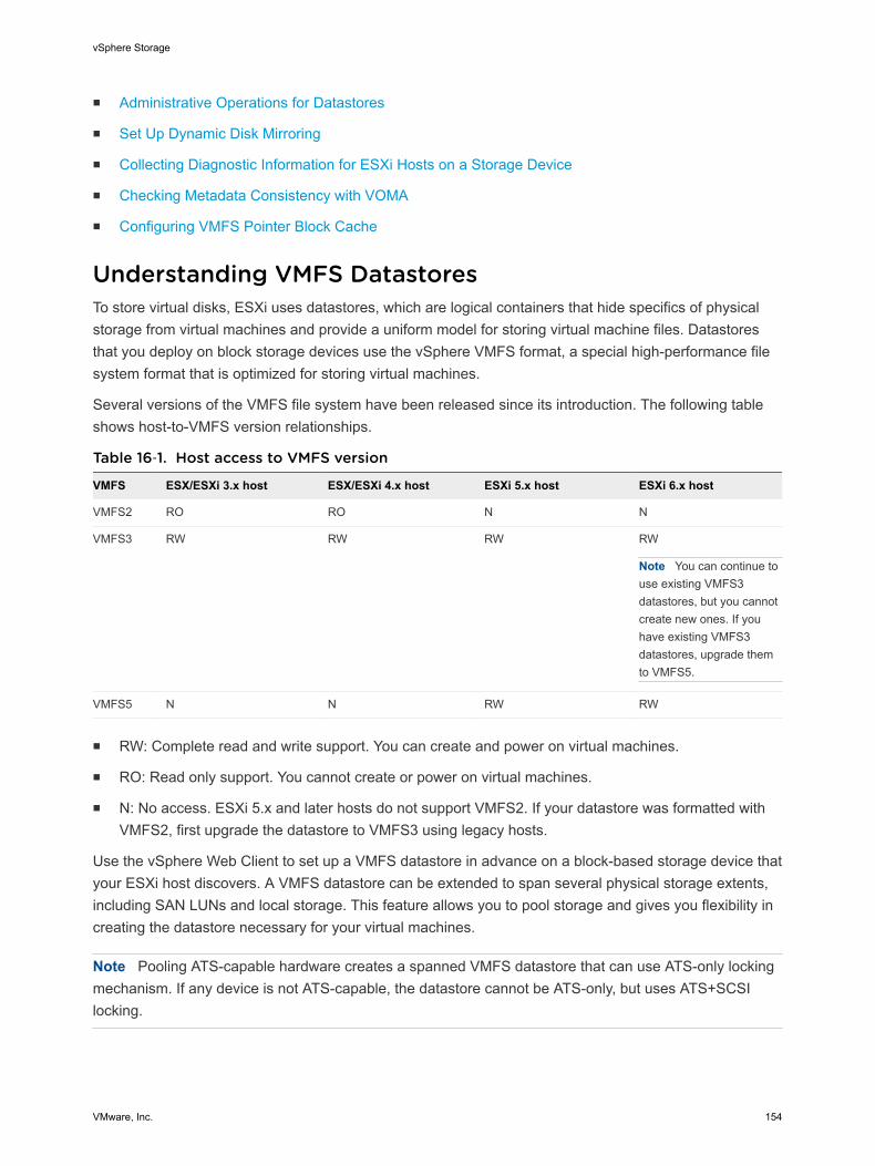
n Administrative Operations for Datastores
n Set Up Dynamic Disk Mirroring
n Collecting Diagnostic Information for ESXi Hosts on a Storage Device
n Checking Metadata Consistency with VOMA
n Configuring VMFS Pointer Block Cache
Understanding VMFS DatastoresTo store virtual disks, ESXi uses datastores, which are logical containers that hide specifics of physicalstorage from virtual machines and provide a uniform model for storing virtual machine files. Datastoresthat you deploy on block storage devices use the vSphere VMFS format, a special high-performance filesystem format that is optimized for storing virtual machines.
Several versions of the VMFS file system have been released since its introduction. The following tableshows host-to-VMFS version relationships.
Table 16‑1. Host access to VMFS version
VMFS ESX/ESXi 3.x host ESX/ESXi 4.x host ESXi 5.x host ESXi 6.x host
VMFS2 RO RO N N
VMFS3 RW RW RW RW
Note You can continue touse existing VMFS3datastores, but you cannotcreate new ones. If youhave existing VMFS3datastores, upgrade themto VMFS5.
VMFS5 N N RW RW
n RW: Complete read and write support. You can create and power on virtual machines.
n RO: Read only support. You cannot create or power on virtual machines.
n N: No access. ESXi 5.x and later hosts do not support VMFS2. If your datastore was formatted withVMFS2, first upgrade the datastore to VMFS3 using legacy hosts.
Use the vSphere Web Client to set up a VMFS datastore in advance on a block-based storage device thatyour ESXi host discovers. A VMFS datastore can be extended to span several physical storage extents,including SAN LUNs and local storage. This feature allows you to pool storage and gives you flexibility increating the datastore necessary for your virtual machines.
Note Pooling ATS-capable hardware creates a spanned VMFS datastore that can use ATS-only lockingmechanism. If any device is not ATS-capable, the datastore cannot be ATS-only, but uses ATS+SCSIlocking.
vSphere Storage
VMware, Inc. 154
You can increase the capacity of a datastore while virtual machines are running on the datastore. Thisability lets you add new space to your VMFS datastores as your virtual machine requires it. VMFS isdesigned for concurrent access from multiple physical machines and enforces the appropriate accesscontrols on virtual machine files.
Characteristics of VMFS5 DatastoresVMFS5 provides many improvements in scalability and performance.
VMFS5 has the following Characteristics:
n Greater than 2TB storage devices for each VMFS5 extent.
n Support of virtual machines with large capacity virtual disks, or disks greater than 2TB.
n Increased resource limits such as file descriptors.
n Standard 1MB file system block size with support of 2TB virtual disks.
n Greater than 2TB disk size for RDMs.
n Support of small files of 1KB.
n Ability to open any file located on a VMFS5 datastore in a shared mode by a maximum of 32 hosts.
n Scalability improvements on storage devices that support hardware acceleration. For information, see Chapter 23 Storage Hardware Acceleration.
n Default use of ATS-only locking mechanisms on storage devices that support ATS. For informationabout ATS-only locking and how to upgrade to ATS-only locking, see VMFS Locking Mechanisms.
n Ability to reclaim physical storage space on thin provisioned storage devices. For information, see Array Thin Provisioning and VMFS Datastores.
n Online upgrade process that upgrades existing datastores without disrupting hosts or virtualmachines that are currently running. For information, see Upgrading VMFS Datastores.
For information about block size limitations of a VMFS datastore, see the VMware knowledge base articleat http://kb.vmware.com/kb/1003565.
VMFS Datastores and Storage Disk FormatsStorage devices that your host supports can use either the master boot record (MBR) format or the GUIDpartition table (GPT) format.
If you create a new VMFS5 datastore, the device is formatted with GPT. The GPT format enables you tocreate datastores larger than 2TB and up to 64TB for a single extent.
VMFS3 datastores continue to use the MBR format for their storage devices. Consider the following itemswhen you work with VMFS3 datastores:
n For VMFS3 datastores, the 2TB limit still applies, even when the storage device has a capacity ofmore than 2TB. To be able to use the entire storage space, upgrade a VMFS3 datastore to VMFS5.Conversion of the MBR format to GPT happens only after you expand the datastore to a size largerthan 2TB.
vSphere Storage
VMware, Inc. 155
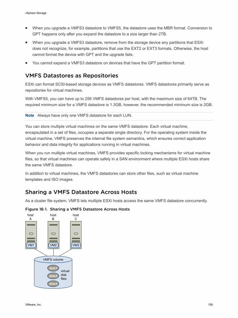
n When you upgrade a VMFS3 datastore to VMFS5, the datastore uses the MBR format. Conversion toGPT happens only after you expand the datastore to a size larger than 2TB.
n When you upgrade a VMFS3 datastore, remove from the storage device any partitions that ESXidoes not recognize, for example, partitions that use the EXT2 or EXT3 formats. Otherwise, the hostcannot format the device with GPT and the upgrade fails.
n You cannot expand a VMFS3 datastore on devices that have the GPT partition format.
VMFS Datastores as RepositoriesESXi can format SCSI-based storage devices as VMFS datastores. VMFS datastores primarily serve asrepositories for virtual machines.
With VMFS5, you can have up to 256 VMFS datastores per host, with the maximum size of 64TB. Therequired minimum size for a VMFS datastore is 1.3GB, however, the recommended minimum size is 2GB.
Note Always have only one VMFS datastore for each LUN.
You can store multiple virtual machines on the same VMFS datastore. Each virtual machine,encapsulated in a set of files, occupies a separate single directory. For the operating system inside thevirtual machine, VMFS preserves the internal file system semantics, which ensures correct applicationbehavior and data integrity for applications running in virtual machines.
When you run multiple virtual machines, VMFS provides specific locking mechanisms for virtual machinefiles, so that virtual machines can operate safely in a SAN environment where multiple ESXi hosts sharethe same VMFS datastore.
In addition to virtual machines, the VMFS datastores can store other files, such as virtual machinetemplates and ISO images.
Sharing a VMFS Datastore Across HostsAs a cluster file system, VMFS lets multiple ESXi hosts access the same VMFS datastore concurrently.
Figure 16‑1. Sharing a VMFS Datastore Across Hosts
VMFS volume
hostA
hostB
hostC
virtualdiskfiles
VM1 VM2 VM3
disk1
disk2
disk3
vSphere Storage
VMware, Inc. 156
For information on the maximum number of hosts that can connect to a single VMFS datastore, see theConfiguration Maximums document.
To ensure that the same virtual machine is not accessed by multiple servers at the same time, VMFSprovides on-disk locking.
Sharing the same VMFS volume across multiple hosts offers the following advantages:
n You can use VMware Distributed Resource Scheduling (DRS) and VMware High Availability (HA).
You can distribute virtual machines across different physical servers. That means you run a mix ofvirtual machines on each server so that not all experience high demand in the same area at the sametime. If a server fails, you can restart virtual machines on another physical server. In case of a failure,the on-disk lock for each virtual machine is released. For more information about VMware DRS, seethe vSphere Resource Management documentation. For information about VMware HA, see thevSphere Availability documentation.
n You can use vMotion to migrate running virtual machines from one physical server to another. Forinformation about migrating virtual machines, see the vCenter Server and Host Managementdocumentation.
VMFS Metadata UpdatesA VMFS datastore holds virtual machine files, directories, symbolic links, RDM descriptor files, and so on.The datastore also maintains a consistent view of all the mapping information for these objects. Thismapping information is called metadata.
Metadata is updated each time you perform datastore or virtual machine management operations.Examples of operations requiring metadata updates include the following:
n Creating, growing, or locking a virtual machine file
n Changing a file's attributes
n Powering a virtual machine on or off
n Creating or deleting a VMFS datastore
n Expanding a VMFS datastore
n Creating a template
n Deploying a virtual machine from a template
n Migrating a virtual machine with vMotion
When metadata changes are made in a shared storage enviroment, VMFS uses special lockingmechanisms to protect its data and prevent multiple hosts from concurrently writing to the metadata.
VMFS Locking MechanismsIn a shared storage environment, when multiple hosts access the same VMFS datastore, specific lockingmechanisms are used. These locking mechanisms prevent multiple hosts from concurrently writing to themetadata and ensure that no data corruption occurs.
vSphere Storage
VMware, Inc. 157
Depending on its configuration and the type of underlying storage, a VMFS datastore can exclusively usethe atomic test and set locking mechanism (ATS-only), or use a combination of ATS and SCSIreservations (ATS+SCSI).
ATS-Only MechanismFor storage devices that support T10 standard-based VAAI specifications, VMFS provides ATS locking,also called hardware assisted locking. The ATS algorithm supports discrete locking per disk sector. Allnewly formatted VMFS5 datastores use the ATS-only mechanism if the underlying storage supports it,and never use SCSI reservations.
When you create a multi-extent datastore where ATS is used, vCenter Server filters out non-ATS devices.This filtering allows you to use only those devices that support the ATS primitive.
In certain cases, you might need to turn off the ATS-only setting for a VMFS5 datastore. For information,see Change Locking Mechanism to ATS+SCSI.
ATS+SCSI MechanismA VMFS datastore that supports the ATS+SCSI mechanism is configured to use ATS and attempts to useit when possible. If ATS fails, the VMFS datastore reverts to SCSI reservations. In contrast with the ATSlocking, the SCSI reservations lock an entire storage device while an operation that requires metadataprotection is performed. After the operation completes, VMFS releases the reservation and otheroperations can continue.
Datastores that use the ATS+SCSI mechanism include VMFS5 datastores that were upgraded fromVMFS3. In addition, new VMFS5 datastores on storage devices that do not support ATS use the ATS+SCSI mechanism.
If your VMFS datastore reverts to SCSI reservations, you might notice performance degradation causedby excessive SCSI reservations. For information about how to reduce SCSI reservations, see thevSphere Troubleshooting documentation.
Display VMFS Locking InformationUse the esxcli command to obtain information about the locking mechanism that a VMFS datastoreuses.
In the procedure, --server=server_name specifies the target server. The specified target serverprompts you for a user name and password. Other connection options, such as a configuration file orsession file, are supported. For a list of connection options, see Getting Started with vSphere Command-Line Interfaces.
Prerequisites
Install vCLI or deploy the vSphere Management Assistant (vMA) virtual machine. See Getting Started withvSphere Command-Line Interfaces. For troubleshooting, run esxcli commands in the ESXi Shell.
vSphere Storage
VMware, Inc. 158
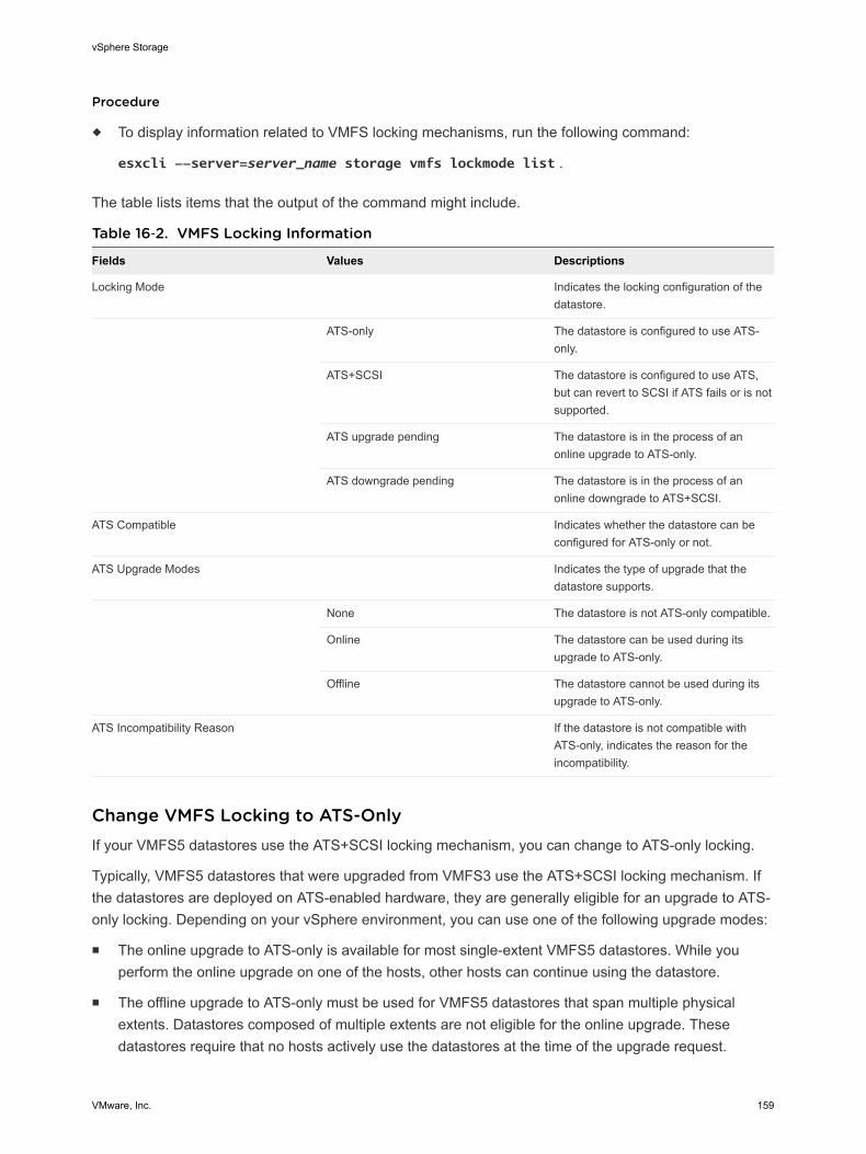
Procedure
u To display information related to VMFS locking mechanisms, run the following command:
esxcli --server=server_name storage vmfs lockmode list .
The table lists items that the output of the command might include.
Table 16‑2. VMFS Locking Information
Fields Values Descriptions
Locking Mode Indicates the locking configuration of thedatastore.
ATS-only The datastore is configured to use ATS-only.
ATS+SCSI The datastore is configured to use ATS,but can revert to SCSI if ATS fails or is notsupported.
ATS upgrade pending The datastore is in the process of anonline upgrade to ATS-only.
ATS downgrade pending The datastore is in the process of anonline downgrade to ATS+SCSI.
ATS Compatible Indicates whether the datastore can beconfigured for ATS-only or not.
ATS Upgrade Modes Indicates the type of upgrade that thedatastore supports.
None The datastore is not ATS-only compatible.
Online The datastore can be used during itsupgrade to ATS-only.
Offline The datastore cannot be used during itsupgrade to ATS-only.
ATS Incompatibility Reason If the datastore is not compatible withATS-only, indicates the reason for theincompatibility.
Change VMFS Locking to ATS-OnlyIf your VMFS5 datastores use the ATS+SCSI locking mechanism, you can change to ATS-only locking.
Typically, VMFS5 datastores that were upgraded from VMFS3 use the ATS+SCSI locking mechanism. Ifthe datastores are deployed on ATS-enabled hardware, they are generally eligible for an upgrade to ATS-only locking. Depending on your vSphere environment, you can use one of the following upgrade modes:
n The online upgrade to ATS-only is available for most single-extent VMFS5 datastores. While youperform the online upgrade on one of the hosts, other hosts can continue using the datastore.
n The offline upgrade to ATS-only must be used for VMFS5 datastores that span multiple physicalextents. Datastores composed of multiple extents are not eligible for the online upgrade. Thesedatastores require that no hosts actively use the datastores at the time of the upgrade request.
vSphere Storage
VMware, Inc. 159
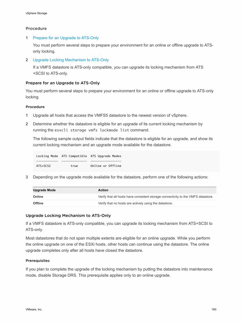
Procedure
1 Prepare for an Upgrade to ATS-Only
You must perform several steps to prepare your environment for an online or offline upgrade to ATS-only locking.
2 Upgrade Locking Mechanism to ATS-Only
If a VMFS datastore is ATS-only compatible, you can upgrade its locking mechanism from ATS+SCSI to ATS-only.
Prepare for an Upgrade to ATS-Only
You must perform several steps to prepare your environment for an online or offline upgrade to ATS-onlylocking.
Procedure
1 Upgrade all hosts that access the VMFS5 datastore to the newest version of vSphere.
2 Determine whether the datastore is eligible for an upgrade of its current locking mechanism byrunning the esxcli storage vmfs lockmode list command.
The following sample output fields indicate that the datastore is eligible for an upgrade, and show itscurrent locking mechanism and an upgrade mode available for the datastore.
Locking Mode ATS Compatible ATS Upgrade Modes
------------ -------------- -----------------
ATS+SCSI true Online or Offline
3 Depending on the upgrade mode available for the datastore, perform one of the following actions:
Upgrade Mode Action
Online Verify that all hosts have consistent storage connectivity to the VMFS datastore.
Offline Verify that no hosts are actively using the datastore.
Upgrade Locking Mechanism to ATS-Only
If a VMFS datastore is ATS-only compatible, you can upgrade its locking mechanism from ATS+SCSI toATS-only.
Most datastores that do not span multiple extents are eligible for an online upgrade. While you performthe online upgrade on one of the ESXi hosts, other hosts can continue using the datastore. The onlineupgrade completes only after all hosts have closed the datastore.
Prerequisites
If you plan to complete the upgrade of the locking mechanism by putting the datastore into maintenancemode, disable Storage DRS. This prerequisite applies only to an online upgrade.
vSphere Storage
VMware, Inc. 160

Procedure
1 Perform an upgrade of the locking mechanism by running the following command:
esxcli storage vmfs lockmode set -a|--ats -l|--volume-label= VMFS label -u|--volume-uuid= VMFS UUID.
2 For an online upgrade, perform additional steps.
a Close the datastore on all hosts that have access to the datastore, so that the hosts canrecognise the change.
You can use one of the following methods:
n Unmount and mount the datastore.
n Put the datastore into maintenance mode and exit maintenance mode.
b Verify that the Locking Mode status for the datastore changed to ATS-only by running:
esxcli storage vmfs lockmode list
c If the Locking Mode displays any other status, for example ATS UPGRADE PENDING, checkwhich host has not yet processed the upgrade by running:
esxcli storage vmfs host list
Change Locking Mechanism to ATS+SCSIWhen you create a VMFS5 datastore on a device that supports atomic test and set (ATS) locking, thedatastore is set to use the ATS-only locking mechanism. In certain circumstances, you might need todowngrade the ATS-only locking to ATS+SCSI.
You might need to switch to the ATS+SCSI locking mechanism when, for example, your storage device isdowngraded or firmware updates fail and the device no longer supports ATS.
The downgrade process is similar to the ATS-only upgrade. As with the upgrade, depending on yourstorage configuration, you can perform the downgrade in online or offline mode.
Procedure
1 Change the locking mechanism to ATS+SCSI by running the following command:
esxcli storage vmfs lockmode set -s|--scsi -l|--volume-label= VMFS label -u|--volume-uuid= VMFS UUID.
2 For an online mode, close the datastore on all hosts that have access to the datastore, so that thehosts can recognise the change.
Understanding Network File System DatastoresAn NFS client built into ESXi uses the Network File System (NFS) protocol over TCP/IP to access adesignated NFS volume that is located on a NAS server. The ESXi host can mount the volume and use itfor its storage needs. vSphere supports versions 3 and 4.1 of the NFS protocol.
vSphere Storage
VMware, Inc. 161
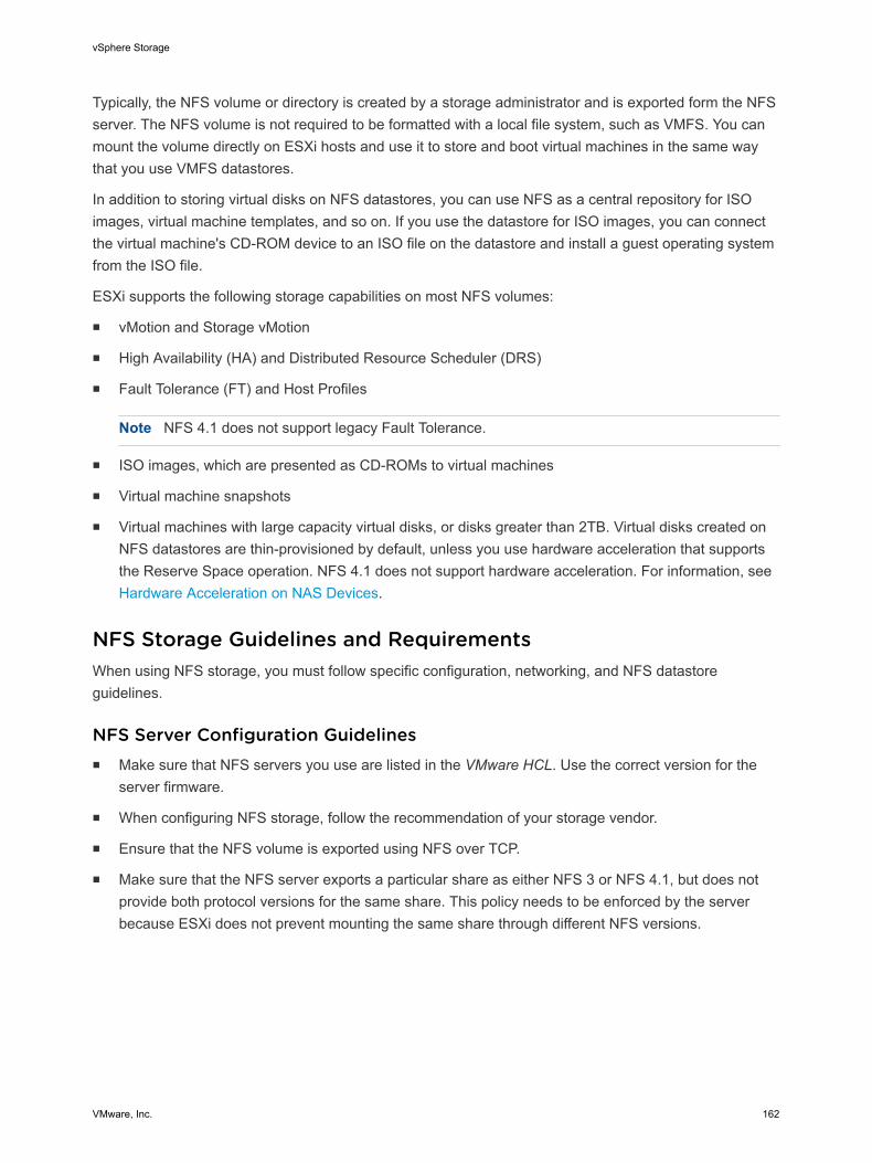
Typically, the NFS volume or directory is created by a storage administrator and is exported form the NFSserver. The NFS volume is not required to be formatted with a local file system, such as VMFS. You canmount the volume directly on ESXi hosts and use it to store and boot virtual machines in the same waythat you use VMFS datastores.
In addition to storing virtual disks on NFS datastores, you can use NFS as a central repository for ISOimages, virtual machine templates, and so on. If you use the datastore for ISO images, you can connectthe virtual machine's CD-ROM device to an ISO file on the datastore and install a guest operating systemfrom the ISO file.
ESXi supports the following storage capabilities on most NFS volumes:
n vMotion and Storage vMotion
n High Availability (HA) and Distributed Resource Scheduler (DRS)
n Fault Tolerance (FT) and Host Profiles
Note NFS 4.1 does not support legacy Fault Tolerance.
n ISO images, which are presented as CD-ROMs to virtual machines
n Virtual machine snapshots
n Virtual machines with large capacity virtual disks, or disks greater than 2TB. Virtual disks created onNFS datastores are thin-provisioned by default, unless you use hardware acceleration that supportsthe Reserve Space operation. NFS 4.1 does not support hardware acceleration. For information, see Hardware Acceleration on NAS Devices.
NFS Storage Guidelines and RequirementsWhen using NFS storage, you must follow specific configuration, networking, and NFS datastoreguidelines.
NFS Server Configuration Guidelinesn Make sure that NFS servers you use are listed in the VMware HCL. Use the correct version for the
server firmware.
n When configuring NFS storage, follow the recommendation of your storage vendor.
n Ensure that the NFS volume is exported using NFS over TCP.
n Make sure that the NFS server exports a particular share as either NFS 3 or NFS 4.1, but does notprovide both protocol versions for the same share. This policy needs to be enforced by the serverbecause ESXi does not prevent mounting the same share through different NFS versions.
vSphere Storage
VMware, Inc. 162
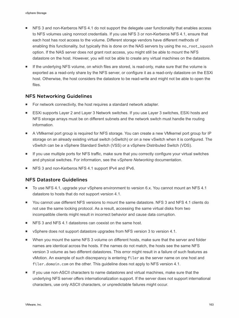
n NFS 3 and non-Kerberos NFS 4.1 do not support the delegate user functionality that enables accessto NFS volumes using nonroot credentials. If you use NFS 3 or non-Kerberos NFS 4.1, ensure thateach host has root access to the volume. Different storage vendors have different methods ofenabling this functionality, but typically this is done on the NAS servers by using the no_root_squashoption. If the NAS server does not grant root access, you might still be able to mount the NFSdatastore on the host. However, you will not be able to create any virtual machines on the datastore.
n If the underlying NFS volume, on which files are stored, is read-only, make sure that the volume isexported as a read-only share by the NFS server, or configure it as a read-only datastore on the ESXihost. Otherwise, the host considers the datastore to be read-write and might not be able to open thefiles.
NFS Networking Guidelinesn For network connectivity, the host requires a standard network adapter.
n ESXi supports Layer 2 and Layer 3 Network switches. If you use Layer 3 switches, ESXi hosts andNFS storage arrays must be on different subnets and the network switch must handle the routinginformation.
n A VMkernel port group is required for NFS storage. You can create a new VMkernel port group for IPstorage on an already existing virtual switch (vSwitch) or on a new vSwitch when it is configured. ThevSwitch can be a vSphere Standard Switch (VSS) or a vSphere Distributed Switch (VDS).
n If you use multiple ports for NFS traffic, make sure that you correctly configure your virtual switchesand physical switches. For information, see the vSphere Networking documentation.
n NFS 3 and non-Kerberos NFS 4.1 support IPv4 and IPv6.
NFS Datastore Guidelinesn To use NFS 4.1, upgrade your vSphere environment to version 6.x. You cannot mount an NFS 4.1
datastore to hosts that do not support version 4.1.
n You cannot use different NFS versions to mount the same datastore. NFS 3 and NFS 4.1 clients donot use the same locking protocol. As a result, accessing the same virtual disks from twoincompatible clients might result in incorrect behavior and cause data corruption.
n NFS 3 and NFS 4.1 datastores can coexist on the same host.
n vSphere does not support datastore upgrades from NFS version 3 to version 4.1.
n When you mount the same NFS 3 volume on different hosts, make sure that the server and foldernames are identical across the hosts. If the names do not match, the hosts see the same NFSversion 3 volume as two different datastores. This error might result in a failure of such features asvMotion. An example of such discrepancy is entering filer as the server name on one host andfiler.domain.com on the other. This guideline does not apply to NFS version 4.1.
n If you use non-ASCII characters to name datastores and virtual machines, make sure that theunderlying NFS server offers internationalization support. If the server does not support internationalcharacters, use only ASCII characters, or unpredictable failures might occur.
vSphere Storage
VMware, Inc. 163
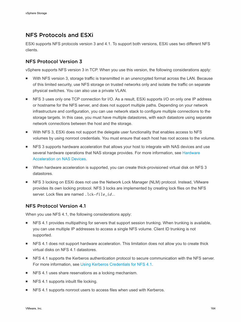
NFS Protocols and ESXiESXi supports NFS protocols version 3 and 4.1. To support both versions, ESXi uses two different NFSclients.
NFS Protocol Version 3vSphere supports NFS version 3 in TCP. When you use this version, the following considerations apply:
n With NFS version 3, storage traffic is transmitted in an unencrypted format across the LAN. Becauseof this limited security, use NFS storage on trusted networks only and isolate the traffic on separatephysical switches. You can also use a private VLAN.
n NFS 3 uses only one TCP connection for I/O. As a result, ESXi supports I/O on only one IP addressor hostname for the NFS server, and does not support multiple paths. Depending on your networkinfrastructure and configuration, you can use network stack to configure multiple connections to thestorage targets. In this case, you must have multiple datastores, with each datastore using separatenetwork connections between the host and the storage.
n With NFS 3, ESXi does not support the delegate user functionality that enables access to NFSvolumes by using nonroot credentials. You must ensure that each host has root access to the volume.
n NFS 3 supports hardware acceleration that allows your host to integrate with NAS devices and useseveral hardware operations that NAS storage provides. For more information, see HardwareAcceleration on NAS Devices.
n When hardware acceleration is supported, you can create thick-provisioned virtual disk on NFS 3datastores.
n NFS 3 locking on ESXi does not use the Network Lock Manager (NLM) protocol. Instead, VMwareprovides its own locking protocol. NFS 3 locks are implemented by creating lock files on the NFSserver. Lock files are named .lck-file_id..
NFS Protocol Version 4.1When you use NFS 4.1, the following considerations apply:
n NFS 4.1 provides multipathing for servers that support session trunking. When trunking is available,you can use multiple IP addresses to access a single NFS volume. Client ID trunking is notsupported.
n NFS 4.1 does not support hardware acceleration. This limitation does not allow you to create thickvirtual disks on NFS 4.1 datastores.
n NFS 4.1 supports the Kerberos authentication protocol to secure communication with the NFS server.For more information, see Using Kerberos Credentials for NFS 4.1.
n NFS 4.1 uses share reservations as a locking mechanism.
n NFS 4.1 supports inbuilt file locking.
n NFS 4.1 supports nonroot users to access files when used with Kerberos.
vSphere Storage
VMware, Inc. 164
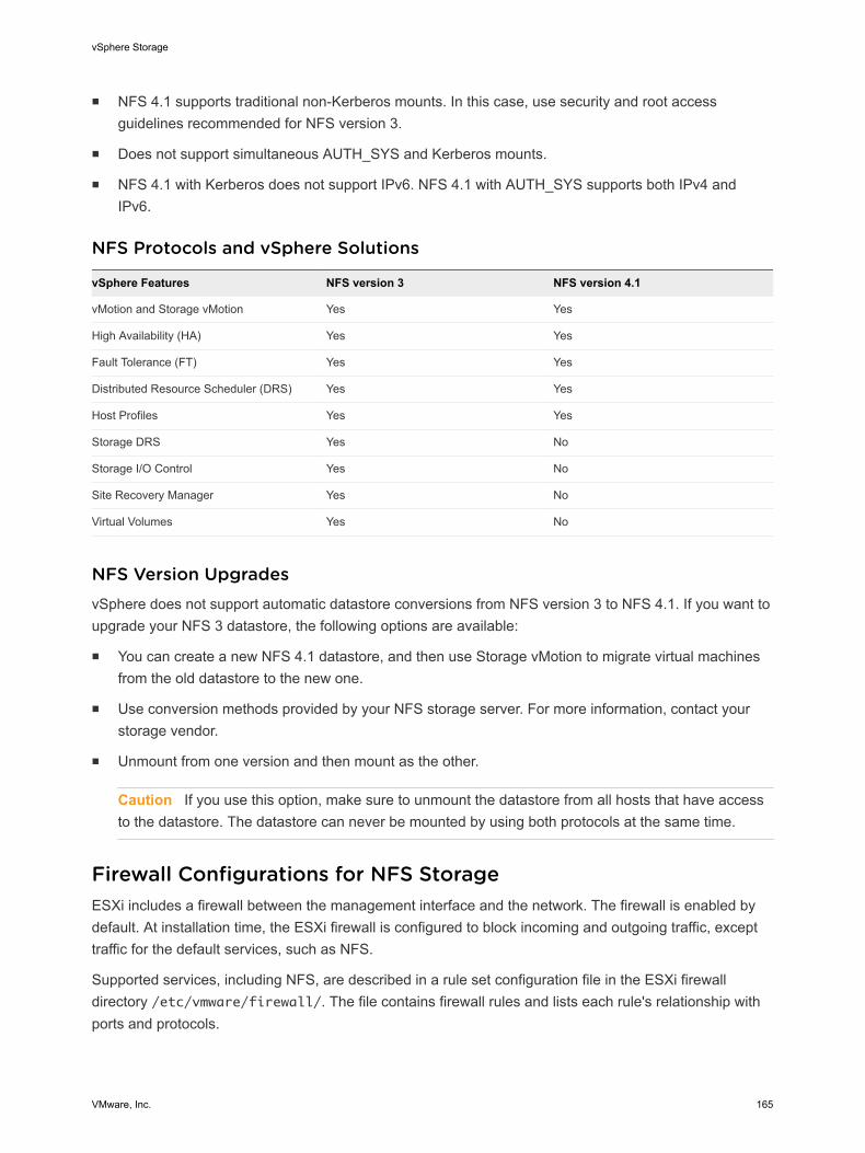
n NFS 4.1 supports traditional non-Kerberos mounts. In this case, use security and root accessguidelines recommended for NFS version 3.
n Does not support simultaneous AUTH_SYS and Kerberos mounts.
n NFS 4.1 with Kerberos does not support IPv6. NFS 4.1 with AUTH_SYS supports both IPv4 andIPv6.
NFS Protocols and vSphere Solutions
vSphere Features NFS version 3 NFS version 4.1
vMotion and Storage vMotion Yes Yes
High Availability (HA) Yes Yes
Fault Tolerance (FT) Yes Yes
Distributed Resource Scheduler (DRS) Yes Yes
Host Profiles Yes Yes
Storage DRS Yes No
Storage I/O Control Yes No
Site Recovery Manager Yes No
Virtual Volumes Yes No
NFS Version UpgradesvSphere does not support automatic datastore conversions from NFS version 3 to NFS 4.1. If you want toupgrade your NFS 3 datastore, the following options are available:
n You can create a new NFS 4.1 datastore, and then use Storage vMotion to migrate virtual machinesfrom the old datastore to the new one.
n Use conversion methods provided by your NFS storage server. For more information, contact yourstorage vendor.
n Unmount from one version and then mount as the other.
Caution If you use this option, make sure to unmount the datastore from all hosts that have accessto the datastore. The datastore can never be mounted by using both protocols at the same time.
Firewall Configurations for NFS StorageESXi includes a firewall between the management interface and the network. The firewall is enabled bydefault. At installation time, the ESXi firewall is configured to block incoming and outgoing traffic, excepttraffic for the default services, such as NFS.
Supported services, including NFS, are described in a rule set configuration file in the ESXi firewalldirectory /etc/vmware/firewall/. The file contains firewall rules and lists each rule's relationship withports and protocols.
vSphere Storage
VMware, Inc. 165
The behavior of the NFS Client rule set (nfsClient) is different from other rule sets. When the NFSClient rule set is enabled, all outbound TCP ports are open for the destination hosts in the list of allowedIP addresses.
The NFS 4.1 rule set opens outgoing connections to destination port 2049, which is the port named in thespecification for version 4.1 protocol. The outgoing connections are open for all IP addresses at the timeof the first mount. This port remains open until the ESXi host is rebooted.
For more information about firewall configurations, see the vSphere Security documentation.
NFS Client Firewall BehaviorThe NFS Client firewall rule set behaves differently than other ESXi firewall rule sets. ESXi configuresNFS Client settings when you mount or unmount an NFS datastore. The behavior differs for differentversions of NFS.
When you add, mount, or unmount an NFS datastore, the resulting behavior depends on the version ofNFS.
NFS v3 Firewall Behavior
When you add or mount an NFS v3 datastore, ESXi checks the state of the NFS Client (nfsClient)firewall rule set.
n If the nfsClient rule set is disabled, ESXi enables the rule set and disables the Allow All IPAddresses policy by setting the allowedAll flag to FALSE. The IP address of the NFS server isadded to the allowed list of outgoing IP addresses.
n If the nfsClient rule set is enabled, the state of the rule set and the allowed IP address policy arenot changed. The IP address of the NFS server is added to the allowed list of outgoing IP addresses.
Note If you manually enable the nfsClient rule set or manually set the Allow All IP Addresses policy,either before or after you add an NFS v3 datastore to the system, your settings are overridden when thelast NFS v3 datastore is unmounted. The nfsClient rule set is disabled when all NFS v3 datastores areunmounted.
When you remove or unmount an NFS v3 datastore, ESXi performs one of the following actions.
n If none of the remaining NFS v3 datastores are mounted from the server of the datastore beingunmounted, ESXi removes the server's IP address from the list of outgoing IP addresses.
n If no mounted NFS v3 datastores remain after the unmount operation, ESXi disables the nfsClientfirewall rule set.
NFS v4.1 Firewall Behavior
When you mount the first NFS v4.1 datastore, ESXi enables the nfs41client rule set and sets itsallowedAll flag to TRUE. This action opens port 2049 for all IP addresses. Unmounting an NFS v4.1datastore does not affect the firewall state. That is, the first NFS v4.1 mount opens port 2049 and that portremains enabled unless you close it explicitly.
vSphere Storage
VMware, Inc. 166
Verify Firewall Ports for NFS ClientsTo enable access to NFS storage, ESXi automatically opens firewall ports for the NFS clients when youmount an NFS datastore. For troubleshooting reasons, you might need to verify that the ports are open.
Procedure
1 In the vSphere Web Client, select the ESXi host.
2 Click the Manage tab, and click Settings.
3 Select Security Profile in the System area, and click Edit.
4 Scroll down to an appropriate version of NFS to make sure that the port is opened.
Using Layer 3 Routed Connections to Access NFS StorageWhen you use Layer 3 (L3) routed connections to access NFS storage, consider certain requirementsand restructions.
Ensure that your environment meets the following requirements:
n Use Cisco's Hot Standby Router Protocol (HSRP) in IP Router. If you are using non-Cisco router, besure to use Virtual Router Redundancy Protocol (VRRP) instead.
n Use Quality of Service (QoS) to prioritize NFS L3 traffic on networks with limited bandwidths, or onnetworks that experience congestion. See your router documentation for details.
n Follow Routed NFS L3 best practices recommended by storage vendor. Contact your storage vendorfor details.
n Disable Network I/O Resource Management (NetIORM).
n If you are planning to use systems with top-of-rack switches or switch-dependent I/O devicepartitioning, contact your system vendor for compatibility and support.
In an L3 environment the following restrictions apply:
n The environment does not support VMware Site Recovery Manager.
n The environment supports only the NFS protocol. Do not use other storage protocols such as FCoEover the same physical network.
n The NFS traffic in this environment does not support IPv6.
n The NFS traffic in this environment can be routed only over a LAN. Other environments such as WANare not supported.
Set Up NFS Storage EnvironmentYou must perform several configuration steps before you mount an NFS datastore in vSphere.
Prerequisites
n Familiarize yourself with the guidelines in NFS Storage Guidelines and Requirements.
vSphere Storage
VMware, Inc. 167
n For details on configuring NFS storage, consult your storage vendor documentation.
Procedure
1 On the NFS server, configure an NFS volume and export it to be mounted on the ESXi hosts.
a Note the IP address or the DNS name of the NFS server and the full path, or folder name, for theNFS share.
For NFS 4.1 you can collect multiple IP addresses or DNS names to take advantage of themultipathing support that an NFS 4.1 datastore provides. NFS 3 and non-Kerberos NFS 4.1support IPv4 and IPv6 addresses.
b If you plan to use Kerberos authentication with NFS 4.1, specify the Kerberos credentials to beused by ESXi for authentication.
2 On each ESXi host, configure a VMkernel Network port for NFS traffic.
For more information, see the vSphere Networking documentation.
3 If you plan to use Kerberos authentication with the NFS 4.1 datastore, configure the ESXi hosts forKerberos authentication.
Make sure that each host that mounts this datastore is a part of an Active Directory domain and itsNFS authentication credentials are set.
What to do next
You can now create an NFS datastore on the ESXi hosts.
Using Kerberos Credentials for NFS 4.1With NFS version 4.1, ESXi supports Kerberos authentication mechanism.
Kerberos is an authentication service that allows an NFS 4.1 client installed on ESXi to prove its identityto an NFS server before mounting an NFS share. Kerberos uses cryptography to work across an insecurenetwork connection. The vSphere implementation of Kerberos for NFS 4.1 supports only identityverification for the client and server, but does not provide data integrity or confidentiality services.
When you use Kerberos authentication, the following considerations apply:
n ESXi uses Kerberos version 5 with Active Directory domain and Key Distribution Center (KDC).
n As a vSphere administrator, you specify Active Directory credentials to provide an access to NFS 4.1Kerberos datastores to an NFS user. A single set of credentials is used to access all Kerberosdatastores mounted on that host.
n When multiple ESXi hosts share the same NFS 4.1 datastore, you must use the same ActiveDirectory credentials for all hosts that access the shared datastore. You can automate this by settingthe user in host profiles and applying the profile to all ESXi hosts.
n NFS 4.1 does not support simultaneous AUTH_SYS and Kerberos mounts.
n NFS 4.1 with Kerberos does not support IPv6. Only IPv4 is supported.
vSphere Storage
VMware, Inc. 168
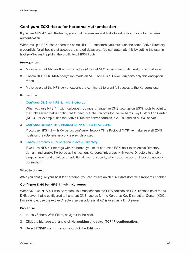
Configure ESXi Hosts for Kerberos AuthenticationIf you use NFS 4.1 with Kerberos, you must perform several tasks to set up your hosts for Kerberosauthentication.
When multiple ESXi hosts share the same NFS 4.1 datastore, you must use the same Active Directorycredentials for all hosts that access the shared datastore. You can automate this by setting the user inhost profiles and applying the profile to all ESXi hosts.
Prerequisites
n Make sure that Microsoft Active Directory (AD) and NFS servers are configured to use Kerberos.
n Enable DES-CBC-MD5 encryption mode on AD. The NFS 4.1 client supports only this encryptionmode.
n Make sure that the NFS server exports are configured to grant full access to the Kerberos user.
Procedure
1 Configure DNS for NFS 4.1 with Kerberos
When you use NFS 4.1 with Kerberos, you must change the DNS settings on ESXi hosts to point tothe DNS server that is configured to hand out DNS records for the Kerberos Key Distribution Center(KDC). For example, use the Active Directory server address, if AD is used as a DNS server.
2 Configure Network Time Protocol for NFS 4.1 with Kerberos
If you use NFS 4.1 with Kerberos, configure Network Time Protocol (NTP) to make sure all ESXihosts on the vSphere network are synchronized.
3 Enable Kerberos Authentication in Active Directory
If you use NFS 4.1 storage with Kerberos, you must add each ESXi host to an Active Directorydomain and enable Kerberos authentication. Kerberos integrates with Active Directory to enablesingle sign-on and provides an additional layer of security when used across an insecure networkconnection.
What to do next
After you configure your host for Kerberos, you can create an NFS 4.1 datastore with Kerberos enabled.
Configure DNS for NFS 4.1 with Kerberos
When you use NFS 4.1 with Kerberos, you must change the DNS settings on ESXi hosts to point to theDNS server that is configured to hand out DNS records for the Kerberos Key Distribution Center (KDC).For example, use the Active Directory server address, if AD is used as a DNS server.
Procedure
1 In the vSphere Web Client, navigate to the host.
2 Click the Manage tab, and click Networking and select TCP/IP configuration.
3 Select TCP/IP configuration and click the Edit icon.
vSphere Storage
VMware, Inc. 169
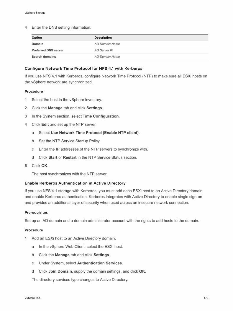
4 Enter the DNS setting information.
Option Description
Domain AD Domain Name
Preferred DNS server AD Server IP
Search domains AD Domain Name
Configure Network Time Protocol for NFS 4.1 with Kerberos
If you use NFS 4.1 with Kerberos, configure Network Time Protocol (NTP) to make sure all ESXi hosts onthe vSphere network are synchronized.
Procedure
1 Select the host in the vSphere inventory.
2 Click the Manage tab and click Settings.
3 In the System section, select Time Configuration.
4 Click Edit and set up the NTP server.
a Select Use Network Time Protocol (Enable NTP client).
b Set the NTP Service Startup Policy.
c Enter the IP addresses of the NTP servers to synchronize with.
d Click Start or Restart in the NTP Service Status section.
5 Click OK.
The host synchronizes with the NTP server.
Enable Kerberos Authentication in Active Directory
If you use NFS 4.1 storage with Kerberos, you must add each ESXi host to an Active Directory domainand enable Kerberos authentication. Kerberos integrates with Active Directory to enable single sign-onand provides an additional layer of security when used across an insecure network connection.
Prerequisites
Set up an AD domain and a domain administrator account with the rights to add hosts to the domain.
Procedure
1 Add an ESXi host to an Active Directory domain.
a In the vSphere Web Client, select the ESXi host.
b Click the Manage tab and click Settings.
c Under System, select Authentication Services.
d Click Join Domain, supply the domain settings, and click OK.
The directory services type changes to Active Directory.
vSphere Storage
VMware, Inc. 170
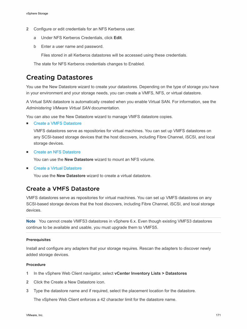
2 Configure or edit credentials for an NFS Kerberos user.
a Under NFS Kerberos Credentials, click Edit.
b Enter a user name and password.
Files stored in all Kerberos datastores will be accessed using these credentials.
The state for NFS Kerberos credentials changes to Enabled.
Creating DatastoresYou use the New Datastore wizard to create your datastores. Depending on the type of storage you havein your environment and your storage needs, you can create a VMFS, NFS, or virtual datastore.
A Virtual SAN datastore is automatically created when you enable Virtual SAN. For information, see theAdministering VMware Virtual SAN documentation.
You can also use the New Datastore wizard to manage VMFS datastore copies.n Create a VMFS Datastore
VMFS datastores serve as repositories for virtual machines. You can set up VMFS datastores onany SCSI-based storage devices that the host discovers, including Fibre Channel, iSCSI, and localstorage devices.
n Create an NFS Datastore
You can use the New Datastore wizard to mount an NFS volume.
n Create a Virtual Datastore
You use the New Datastore wizard to create a virtual datastore.
Create a VMFS DatastoreVMFS datastores serve as repositories for virtual machines. You can set up VMFS datastores on anySCSI-based storage devices that the host discovers, including Fibre Channel, iSCSI, and local storagedevices.
Note You cannot create VMFS3 datastores in vSphere 6.x. Even though existing VMFS3 datastorescontinue to be available and usable, you must upgrade them to VMFS5.
Prerequisites
Install and configure any adapters that your storage requires. Rescan the adapters to discover newlyadded storage devices.
Procedure
1 In the vSphere Web Client navigator, select vCenter Inventory Lists > Datastores
2 Click the Create a New Datastore icon.
3 Type the datastore name and if required, select the placement location for the datastore.
The vSphere Web Client enforces a 42 character limit for the datastore name.
vSphere Storage
VMware, Inc. 171
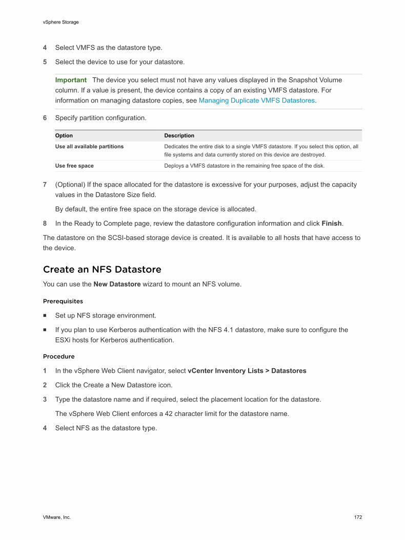
4 Select VMFS as the datastore type.
5 Select the device to use for your datastore.
Important The device you select must not have any values displayed in the Snapshot Volumecolumn. If a value is present, the device contains a copy of an existing VMFS datastore. Forinformation on managing datastore copies, see Managing Duplicate VMFS Datastores.
6 Specify partition configuration.
Option Description
Use all available partitions Dedicates the entire disk to a single VMFS datastore. If you select this option, allfile systems and data currently stored on this device are destroyed.
Use free space Deploys a VMFS datastore in the remaining free space of the disk.
7 (Optional) If the space allocated for the datastore is excessive for your purposes, adjust the capacityvalues in the Datastore Size field.
By default, the entire free space on the storage device is allocated.
8 In the Ready to Complete page, review the datastore configuration information and click Finish.
The datastore on the SCSI-based storage device is created. It is available to all hosts that have access tothe device.
Create an NFS DatastoreYou can use the New Datastore wizard to mount an NFS volume.
Prerequisites
n Set up NFS storage environment.
n If you plan to use Kerberos authentication with the NFS 4.1 datastore, make sure to configure theESXi hosts for Kerberos authentication.
Procedure
1 In the vSphere Web Client navigator, select vCenter Inventory Lists > Datastores
2 Click the Create a New Datastore icon.
3 Type the datastore name and if required, select the placement location for the datastore.
The vSphere Web Client enforces a 42 character limit for the datastore name.
4 Select NFS as the datastore type.
vSphere Storage
VMware, Inc. 172
5 Specify an NFS version.
n NFS 3
n NFS 4.1
Important If multiple hosts access the same datastore, you must use the same protocol on all hosts.
6 Type the server name or IP address and the mount point folder name.
With NFS 4.1, you can add multiple IP addresses or server names if the server supports trunking.The host uses these values to achieve multipathing to the NFS server mount point.
You can use IPv4 or IPv6 addresses for NFS 3 and non-Kerberos NFS 4.1.
7 Select Mount NFS read only if the volume is exported as read-only by the NFS server.
8 If you use Kerberos authentication with NFS 4.1, enable Kerberos on the datastore.
9 If you are creating a datastore at the data center or cluster level, select hosts that mount thedatastore.
10 Review the configuration options and click Finish.
Create a Virtual DatastoreYou use the New Datastore wizard to create a virtual datastore.
Procedure
1 In the vSphere Web Client navigator, select vCenter Inventory Lists > Datastores
2 Click the Create a New Datastore icon.
3 Type the datastore name and if required, select the placement location for the datastore.
Make sure to use the name that does not duplicate another datastore name in your data centerenvironment.
If you mount the same virtual datastore to several hosts, the name of the datastore must beconsistent across all hosts.
4 Select VVOL as the datastore type.
5 From the list of storage containers, select a backing storage container.
6 Select the hosts that require access to the datastore.
7 Review the configuration options and click Finish.
What to do next
After you create the virtual datastore, you can perform such datastore operations as renaming thedatastore, browsing datastore files, unmounting the datastore, and so on.
You cannot add the virtual datastore to a datastore cluster.
vSphere Storage
VMware, Inc. 173
Managing Duplicate VMFS DatastoresWhen a storage device contains a VMFS datastore copy, you can mount the datastore with the existingsignature or assign a new signature.
Each VMFS datastore created in a storage disk has a unique signature, also called UUID, that is stored inthe file system superblock. When the storage disk is replicated or its snapshot is taken on the storageside, the resulting disk copy is identical, byte-for-byte, with the original disk. As a result, if the originalstorage disk contains a VMFS datastore with UUID X, the disk copy appears to contain an identical VMFSdatastore, or a VMFS datastore copy, with exactly the same UUID X.
In addition to LUN snapshotting and replication, the following storage device operations might cause ESXito mark the existing datastore on the device as a copy of the original datastore:
n LUN ID changes
n SCSI device type changes, for example, from SCSI-2 to SCSI-3
n SPC-2 compliancy enablement
ESXi can detect the VMFS datastore copy and display it in the vSphere Web Client. You have an optionof mounting the datastore copy with its original UUID or changing the UUID to resignature the datastore.
Whether you chose resignaturing or mounting without resignaturing depends on how the LUNs aremasked in the storage environment. If your hosts are able to see both copies of the LUN, thenresignaturing is the recommended method. Otherwise, mounting is an option.
Keep Existing Datastore SignatureIf you do not need to resignature a VMFS datastore copy, you can mount it without changing its signature.
You can keep the signature if, for example, you maintain synchronized copies of virtual machines at asecondary site as part of a disaster recovery plan. In the event of a disaster at the primary site, you mountthe datastore copy and power on the virtual machines at the secondary site.
Prerequisites
n Perform a storage rescan on your host to update the view of storage devices presented to the host.
n Unmount the original VMFS datastore that has the same UUID as the copy you plan to mount. Youcan mount the VMFS datastore copy only if it does not collide with the original VMFS datastore.
Procedure
1 In the vSphere Web Client navigator, select vCenter Inventory Lists > Datastores
2 Click the Create a New Datastore icon.
3 Type the datastore name and if required, select the placement location for the datastore.
4 Select VMFS as the datastore type.
vSphere Storage
VMware, Inc. 174
5 From the list of storage devices, select the device that has a specific value displayed in the SnapshotVolume column.
The value present in the Snapshot Volume column indicates that the device is a copy that contains acopy of an existing VMFS datastore.
6 Under Mount Options, select Keep Existing Signature.
7 Review the datastore configuration information and click Finish.
What to do next
If you later want to resignature the mounted datastore, you must unmount it first.
Resignature a VMFS Datastore CopyUse datastore resignaturing if you want to retain the data stored on the VMFS datastore copy.
When resignaturing a VMFS copy, ESXi assigns a new signature (UUID) to the copy, and mounts thecopy as a datastore distinct from the original. All references to the original signature from virtual machineconfiguration files are updated.
When you perform datastore resignaturing, consider the following points:
n Datastore resignaturing is irreversible.
n After resignaturing, the storage device replica that contained the VMFS copy is no longer treated as areplica.
n A spanned datastore can be resignatured only if all its extents are online.
n The resignaturing process is crash and fault tolerant. If the process is interrupted, you can resume itlater.
n You can mount the new VMFS datastore without a risk of its UUID conflicting with UUIDs of any otherdatastore, such as an ancestor or child in a hierarchy of storage device snapshots.
Prerequisites
n Unmount the datastore copy.
n Perform a storage rescan on your host to update the view of storage devices presented to the host.
Procedure
1 In the vSphere Web Client navigator, select vCenter Inventory Lists > Datastores
2 Click the Create a New Datastore icon.
3 Type the datastore name and if required, select the placement location for the datastore.
4 Select VMFS as the datastore type.
vSphere Storage
VMware, Inc. 175
5 From the list of storage devices, select the device that has a specific value displayed in the SnapshotVolume column.
The value present in the Snapshot Volume column indicates that the device is a copy that contains acopy of an existing VMFS datastore.
6 Under Mount Options, select Assign a New Signature and click Next.
7 Review the datastore configuration information and click Finish.
Upgrading VMFS DatastoresIf your datastores were formatted with VMFS2 or VMFS3, you must upgrade the datastores to VMFS5.
When you perform datastore upgrades, consider the following items:
n To upgrade a VMFS2 datastore, you use a two-step process that involves upgrading VMFS2 toVMFS3 first. To access the VMFS2 datastore and perform the VMFS2 to VMFS3 conversion, use anESX/ESXi 4.x or earlier host.
After you upgrade your VMFS2 datastore to VMFS3, the datastore becomes available on the ESXi6.x host, where you complete the process of upgrading to VMFS5.
n You can perform a VMFS3 to VMFS5 upgrade while the datastore is in use with virtual machinespowered on.
n While performing an upgrade, your host preserves all files on the datastore.
n The datastore upgrade is a one-way process. After upgrading your datastore, you cannot revert itback to its previous VMFS format.
An upgraded VMFS5 datastore differs from a newly formatted VMFS5.
Table 16‑3. Comparing Upgraded and Newly Formatted VMFS5 Datastores
Characteristics Upgraded VMFS5 Formatted VMFS5
File block size 1, 2, 4, and 8MB 1MB
Subblock size 64KB 8KB
Partition format MBR. Conversion to GPT happens only afteryou expand the datastore to a size larger than2TB.
GPT
Datastore limits Retains limits of VMFS3 datastore.
VMFS locking mechanism ATS+SCSI ATS-only (on hardware thatsupports ATS)
ATS+SCSI (on hardware thatdoes not support ATS)
For more information about VMFS locking mechanisms and how to upgrade to ATS-only, see VMFSLocking Mechanisms.
vSphere Storage
VMware, Inc. 176
Upgrade a Datastore to VMFS5If you use VMFS3 datastores, you must upgrade them to VMFS5.
You can perform an upgrade while the datastore is in use with virtual machines powered on.
Prerequisites
n If you have a VMFS2 datastore, you must first upgrade it to VMFS3 using an ESX/ESXi 3.x orESX/ESXi 4.x host. Use the vSphere Host Client to access the host.
n All hosts accessing the datastore must support VMFS5.
n Verify that the volume to be upgraded has at least 2 MB of free space. Check the datastore Summarytab for this information.
Procedure
1 In the vSphere Web Client navigator, select vCenter Inventory Lists > Datastores
2 Click the datastore to upgrade.
3 Click the Manage tab, and click Settings.
4 Click Upgrade to VMFS5.
5 Verify that the hosts accessing the datastore support VMFS5.
6 Click OK to start the upgrade.
7 Perform a rescan on all hosts that are associated with the datastore.
The datastore is upgraded to VMFS5 and is available to all hosts that are associated with the datastore.
Increasing VMFS Datastore CapacityIf your VMFS datastore requires more space, increase the datastore capacity. You can dynamicallyincrease the capacity by growing a datastore extent or by adding a new extent.
Use one of the following methods to increase a datastore capacity:
n Dynamically grow any expandable datastore extent, so that it fills the available adjacent capacity. Theextent is considered expandable when the underlying storage device has free space immediatelyafter the extent.
n Dynamically add a new extent. The datastore can span over up to 32 extents with the size of eachextent of more than 2TB, yet appear as a single volume. The spanned VMFS datastore can use anyor all of its extents at any time. It does not need to fill up a particular extent before using the next one.
Note Datastores that only support hardware assisted locking, also called atomic test and set (ATS)mechanism cannot span over non-ATS devices. For more information, see VMFS LockingMechanisms.
vSphere Storage
VMware, Inc. 177
Increase VMFS Datastore CapacityWhen you need to add virtual machines to a datastore, or when the virtual machines running on adatastore require more space, you can dynamically increase the capacity of a VMFS datastore.
If a shared datastore has powered on virtual machines and becomes 100% full, you can increase thedatastore's capacity only from the host with which the powered on virtual machines are registered.
Procedure
1 In the vSphere Web Client navigator, select vCenter Inventory Lists > Datastores
2 Select the datastore to grow and click the Increase Datastore Capacity icon.
3 Select a device from the list of storage devices.
Your selection depends on whether an expandable storage device is available.
Option Description
To expand an existing extent Select the device for which the Expandable column reads YES. A storage deviceis reported as expandable when it has free space immediately after the extent.
To add a new extent Select the device for which the Expandable column reads NO.
4 Review the Current Disk Layout to see the available configurations and click Next.
5 Select a configuration option from the bottom panel.
Depending on the current layout of the disk and on your previous selections, the options you seemight vary.
Option Description
Use free space to add new extent Adds the free space on this disk as a new extent.
Use free space to expand existingextent
Expands an existing extent to a required capacity.
Use free space Deploys an extent in the remaining free space of the disk. This option is availableonly when you are adding an extent.
Use all available partitions Dedicates the entire disk to a single extent. This option is available only when youare adding an extent and when the disk you are formatting is not blank. The diskis reformatted, and the datastores and any data that it contains are erased.
6 Set the capacity for the extent.
The minimum extent size is 1.3GB. By default, the entire free space on the storage device isavailable.
7 Click Next.
8 Review the proposed layout and the new configuration of your datastore, and click Finish.
vSphere Storage
VMware, Inc. 178
Administrative Operations for DatastoresAfter creating datastores, you can perform several administrative operations on the datastores. Certainoperations, such as renaming a datastore, are available for all types of datastores. Others apply tospecific types of datastores.
n Change Datastore Name
You can change the name of an existing datastore.
n Unmount Datastores
When you unmount a datastore, it remains intact, but can no longer be seen from the hosts that youspecify. The datastore continues to appear on other hosts, where it remains mounted.
n Mount Datastores
You can mount a datastore you previously unmounted. You can also mount a datastore on additionalhosts, so that it becomes a shared datastore.
n Remove VMFS Datastores
You can delete any type of VMFS datastore, including copies that you have mounted withoutresignaturing. When you delete a datastore, it is destroyed and disappears from all hosts that haveaccess to the datastore.
n Use Datastore Browser
Use the datastore file browser to manage contents of your datastores. You can browse folders andfiles that are stored on the datastore. You can also use the browser to upload files and performadministrative tasks on your folders and files.
n Turn Off Storage Filters
When you perform VMFS datastore management operations, vCenter Server uses default storageprotection filters. The filters help you to avoid storage corruption by retrieving only the storagedevices that can be used for a particular operation. Unsuitable devices are not displayed forselection. You can turn off the filters to view all devices.
Change Datastore NameYou can change the name of an existing datastore.
Procedure
1 In the vSphere Web Client navigator, select vCenter Inventory Lists > Datastores
2 Select the datastore to rename.
3 Select Rename from the right-click menu.
4 Type a new datastore name.
The vSphere Web Client enforces a 42 character limit for the datastore name.
The new name appears on all hosts that have access to the datastore.
vSphere Storage
VMware, Inc. 179
Unmount DatastoresWhen you unmount a datastore, it remains intact, but can no longer be seen from the hosts that youspecify. The datastore continues to appear on other hosts, where it remains mounted.
Do not perform any configuration operations that might result in I/O to the datastore while the unmount isin progress.
Note Make sure that the datastore is not used by vSphere HA heartbeating. vSphere HA heartbeatingdoes not prevent you from unmounting the datastore. However, if the datastore is used for heartbeating,unmounting it might cause the host to fail and restart any active virtual machine.
Prerequisites
When appropriate, before unmounting datastores, make sure that the following prerequisites are met:
n No virtual machines reside on the datastore.
n The datastore is not managed by Storage DRS.
n Storage I/O control is disabled for this datastore.
Procedure
1 In the vSphere Web Client navigator, select vCenter Inventory Lists > Datastores
2 Right-click the datastore to unmount and select Unmount Datastore.
3 If the datastore is shared, specify which hosts should no longer access the datastore.
4 Confirm that you want to unmount the datastore.
After you unmount a VMFS datastore from all hosts, the datastore is marked as inactive. If you unmountan NFS or a virtual datastore from all hosts, the datastore disappears from the inventory.
What to do next
If you unmounted the VMFS datastore as a part of an orderly storage removal procedure, you can nowdetach the storage device that is backing the datastore. See Detach Storage Devices.
Mount DatastoresYou can mount a datastore you previously unmounted. You can also mount a datastore on additionalhosts, so that it becomes a shared datastore.
A VMFS datastore that has been unmounted from all hosts remains in inventory, but is marked asinaccessible. You can use this task to mount the VMFS datastore to a specified host or multiple hosts.
If you have unmounted an NFS or a virtual datastore from all hosts, the datastore disappears from theinventory. To mount the NFS or virtual datastore that has been removed from the inventory, use the NewDatastore wizard.
vSphere Storage
VMware, Inc. 180
A datastore of any type that is unmounted from some hosts while being mounted on others, is shown asactive in the inventory.
Procedure
1 In the vSphere Web Client navigator, select vCenter Inventory Lists > Datastores
2 Right-click the datastore to mount and select one of the following options:
n Mount Datastore
n Mount Datastore on Additional Hosts
Whether you see one or another option depends on the type of datastore you use.
3 Select the hosts that should access the datastore.
Remove VMFS DatastoresYou can delete any type of VMFS datastore, including copies that you have mounted withoutresignaturing. When you delete a datastore, it is destroyed and disappears from all hosts that haveaccess to the datastore.
Note The datastore delete operation permanently deletes all files associated with virtual machines onthe datastore. Although you can delete the datastore without unmounting, it is preferable that youunmount the datastore first.
Prerequisites
n Remove or migrate all virtual machines from the datastore.
n Make sure that no other host is accessing the datastore.
n Disable Storage DRS for the datastore.
n Disable Storage I/O control for the datastore.
n Make sure that the datastore is not used for vSphere HA heartbeating.
Procedure
1 In the vSphere Web Client navigator, select vCenter Inventory Lists > Datastores
2 Right-click the datastore to remove.
3 Select Delete Datastore.
4 Confirm that you want to remove the datastore.
Use Datastore BrowserUse the datastore file browser to manage contents of your datastores. You can browse folders and filesthat are stored on the datastore. You can also use the browser to upload files and perform administrativetasks on your folders and files.
vSphere Storage
VMware, Inc. 181
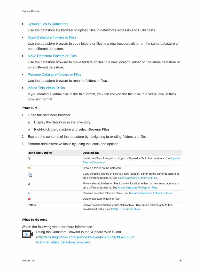
n Upload Files to Datastores
Use the datastore file browser to upload files to datastores accessible to ESXi hosts.
n Copy Datastore Folders or Files
Use the datastore browser to copy folders or files to a new location, either on the same datastore oron a different datastore.
n Move Datastore Folders or Files
Use the datastore browser to move folders or files to a new location, either on the same datastore oron a different datastore.
n Rename Datastore Folders or Files
Use the datastore browser to rename folders or files.
n Inflate Thin Virtual Disks
If you created a virtual disk in the thin format, you can convert the thin disk to a virtual disk in thickprovision format.
Procedure
1 Open the datastore browser.
a Display the datastore in the inventory.
b Right-click the datastore and select Browse Files.
2 Explore the contents of the datastore by navigating to existing folders and files.
3 Perform administrative tasks by using the icons and options.
Icons and Options Descriptions
Install the Client Integration plug-in or Upload a file to the datastore. See UploadFiles to Datastores.
Create a folder on the datastore.
Copy selected folders or files to a new location, either on the same datastore oron a different datastore. See Copy Datastore Folders or Files.
Move selected folders or files to a new location, either on the same datastore oron a different datastore. See Move Datastore Folders or Files.
Rename selected folders or files. See Rename Datastore Folders or Files.
Delete selected folders or files.
Inflate Convert a selected thin virtual disk to thick. This option applies only to thin-provisioned disks. See Inflate Thin Virtual Disks.
What to do next
Watch the following video for more information.Using the Datastore Browser in the vSphere Web Client(http://link.brightcove.com/services/player/bcpid2296383276001?bctid=ref:video_datastore_browser)
vSphere Storage
VMware, Inc. 182
Upload Files to DatastoresUse the datastore file browser to upload files to datastores accessible to ESXi hosts.
In addition to their traditional use as storage for virtual machines files, datastores can serve to store dataor files related to virtual machines. For example, you can upload ISO images of operating systems from alocal computer to a datastore on the host. You then use these images to install guest operating systemson the new virtual machines.
Note Virtual Volumes do not support uploading files directly to the Virtual Volumes datastores. You mustfirst create a folder on the Virtual Volumes datastore, and then upload the files into the folder.
Prerequisites
n Required privilege: Datastore.Browse Datastore
n Point to the icon ( ) and check its label. If the label reads Install the Client Integration plug-in, youmust install the plug-in to be able to upload files. Click the icon and follow the prompts. Afterinstallation, the label changes to Upload a file to the datastore.
Procedure
1 Open the datastore browser.
a Display the datastore in the inventory.
b Right-click the datastore and select Browse Files.
2 (Optional) Create a folder to store the file.
3 Select the target folder and click the Upload a file to the datastore icon ( ).
4 Locate the item to upload on the local computer and click Open.
5 Refresh the datastore file browser to see the uploaded file on the list.
What to do next
You might experience problems when deploying an OVF template that you previously exported and thenuploaded to a datastore. For details and a workaround, see the VMware Knowledge Base article 2117310.
Copy Datastore Folders or FilesUse the datastore browser to copy folders or files to a new location, either on the same datastore or on adifferent datastore.
Virtual disk files are moved or copied without format conversion. If you move a virtual disk to a datastorethat belongs to a host different from the source host, you might need to convert the virtual disk.Otherwise, you might not be able to use the disk.
You cannot copy VM files across vCenter Servers.
vSphere Storage
VMware, Inc. 183
Prerequisites
Required privilege: Datastore.Browse Datastore
Procedure
1 Open the datastore browser.
a Display the datastore in the inventory.
b Right-click the datastore and select Browse Files.
2 Browse to an object you want to copy, either a folder or a file.
3 Select the object and click the Copy selection to a new location icon.
4 Specify the destination location.
5 (Optional) Select Overwrite files and folders with matching names at the destination.
6 Click OK.
Move Datastore Folders or FilesUse the datastore browser to move folders or files to a new location, either on the same datastore or on adifferent datastore.
Note Virtual disk files are moved or copied without format conversion. If you move a virtual disk to adatastore on a different type of host from the source host, you might need to convert the virtual disksbefore you can use them.
Prerequisites
Required privilege: Datastore.Browse Datastore
Procedure
1 Open the datastore browser.
a Display the datastore in the inventory.
b Right-click the datastore and select Browse Files.
2 Browse to an object you want to move, either a folder or a file.
3 Select the object and click the Move selection to a new location icon.
4 Specify the destination location.
5 (Optional) Select Overwrite files and folders with matching names at the destination.
6 Click OK.
Rename Datastore Folders or FilesUse the datastore browser to rename folders or files.
vSphere Storage
VMware, Inc. 184
Prerequisites
Required privilege: Datastore.Browse Datastore
Procedure
1 Open the datastore browser.
a Display the datastore in the inventory.
b Right-click the datastore and select Browse Files.
2 Browse to an object you want to rename, either a folder or a file.
3 Select the object and click the Rename selection icon.
4 Specify the new name and click OK.
Inflate Thin Virtual DisksIf you created a virtual disk in the thin format, you can convert the thin disk to a virtual disk in thickprovision format.
You use the datastore browser to inflate the virtual disk.
Prerequisites
n Make sure that the datastore where the virtual machine resides has enough space.
n Make sure that the virtual disk is thin.
n Remove snapshots.
n Power off your virtual machine.
Procedure
1 Navigate to the folder of the virtual disk you want to inflate.
a In the vSphere Web Client, browse to the virtual machine.
b Double-click the virtual machine to display its information.
c Click the Related Objects tab and click Datastores.
The datastore that stores the virtual machine files is listed.
d Select the datastore and click the Navigate to the datastore file browser icon.
The datastore browser displays contents of the datastore.
2 Open the virtual machine folder and browse to the virtual disk file that you want to convert.
The file has the .vmdk extension and is marked with the virtual disk ( ) icon.
3 Right-click the virtual disk file and select Inflate.
Note The option might not be available if the virtual disk is thick or when the virtual machine isrunning.
vSphere Storage
VMware, Inc. 185
The inflated virtual disk occupies the entire datastore space originally provisioned to it.
Turn Off Storage FiltersWhen you perform VMFS datastore management operations, vCenter Server uses default storageprotection filters. The filters help you to avoid storage corruption by retrieving only the storage devicesthat can be used for a particular operation. Unsuitable devices are not displayed for selection. You canturn off the filters to view all devices.
Prerequisites
Before you change the device filters, consult with the VMware support team. You can turn off the filtersonly if you have other methods to prevent device corruption.
Procedure
1 Browse to the vCenter Server in the vSphere Web Client object navigator.
2 Click the Manage tab, and click Settings.
3 Under Settings, click Advanced Settings, and click Edit.
4 Specify the filter to turn off.
a In the Name text box at the bottom of the page, enter an appropriate filter name.
Name Description
config.vpxd.filter.vmfsFilter VMFS Filter
config.vpxd.filter.rdmFilter RDM Filter
config.vpxd.filter.sameHostsAndTransportsFilter
Same Hosts and Transports Filter
config.vpxd.filter.hostRescanFilter Host Rescan Filter
Note If you turn off this filter, your hosts continue to perform a rescan eachtime you present a new LUN to a host or a cluster.
b In the Value text box, enter False for the specified key.
5 Click Add, and click OK to save your changes.
You are not required to restart the vCenter Server system.
Storage FilteringvCenter Server provides storage filters to help you avoid storage device corruption or performancedegradation that might be caused by an unsupported use of storage devices. These filters are availableby default.
vSphere Storage
VMware, Inc. 186
Table 16‑4. Storage Filters
Filter Name Description
config.vpxd.filter.vmfsFilter
(VMFS Filter)
Filters out storage devices, or LUNs, that are already used by a VMFS datastore on anyhost managed by vCenter Server. The LUNs do not show up as candidates to beformatted with another VMFS datastore or to be used as an RDM.
config.vpxd.filter.rdmFilter
(RDM Filter)
Filters out LUNs that are already referenced by an RDM on any host managed by vCenterServer. The LUNs do not show up as candidates to be formatted with VMFS or to be usedby a different RDM.
For your virtual machines to access the same LUN, the virtual machines must share thesame RDM mapping file. For information about this type of configuration, see the vSphereResource Management documentation.
config.vpxd.filter.sameHostsAndTransportsFilter
(Same Hosts and Transports Filter)
Filters out LUNs ineligible for use as VMFS datastore extents because of host or storagetype incompatibility. Prevents you from adding the following LUNs as extents:n LUNs not exposed to all hosts that share the original VMFS datastore.n LUNs that use a storage type different from the one the original VMFS datastore
uses. For example, you cannot add a Fibre Channel extent to a VMFS datastore on alocal storage device.
config.vpxd.filter.hostRescanFilter
(Host Rescan Filter)
Automatically rescans and updates VMFS datastores after you perform datastoremanagement operations. The filter helps provide a consistent view of all VMFS datastoreson all hosts managed by vCenter Server.
Note If you present a new LUN to a host or a cluster, the hosts automatically perform arescan no matter whether you have the Host Rescan Filter on or off.
Set Up Dynamic Disk MirroringTypically, you cannot use logical-volume manager software on virtual machines to mirror virtual disks.However, if your Microsoft Windows virtual machines support dynamic disks, you can protect the virtualmachines from an unplanned storage device loss by mirroring virtual disks across two SAN LUNs.
Prerequisites
n Use a Windows virtual machine that supports dynamic disks.
n Required privilege: Advanced
Procedure
1 Create a virtual machine with two virtual disks.
Make sure to place the disks on different datastores.
2 Log in to your virtual machine and configure the disks as dynamic mirrored disks.
See Microsoft documentation.
3 After the disks synchronise, power off the virtual machine.
4 Change virtual machine settings to allow the use of dynamic disk mirroring.
a Right-click the virtual machine and select Edit Settings.
b Click the VM Options tab and expand the Advanced menu.
vSphere Storage
VMware, Inc. 187
c Click Edit Configuration next to Configuration Parameters.
d Click Add Row and add the following parameters:
Name Value
scsi#.returnNoConnectDuringAPD True
scsi#.returnBusyOnNoConnectStatus False
e Click OK.
Collecting Diagnostic Information for ESXi Hosts on aStorage DeviceDuring a host failure, ESXi must be able to save diagnostic information to a preconfigured location fordiagnostic and technical support purposes.
Typically, a partition to collect diagnostic information, also called VMkernel core dump, is created on alocal storage device during ESXi installation. You can override this default behavior if, for example, youuse shared storage devices instead of local storage. To prevent automatic formatting of local devices,detach the devices from the host before you install ESXi and power on the host for the first time. You canlater set up a location for collecting diagnostic information on a local or remote storage device.
When you use storage devices, you can select between two options of setting up core dump collection.You can use a preconfigured diagnostic partition on a storage device or use a file on a VMFS datastore.
n Set Up a Device Partition as Core Dump Location
Create a diagnostic partition for your ESXi host.
n Set Up a File as Core Dump Location
If the size of your available core dump partition is insufficient, you can configure ESXi to generatecore dump as a file.
Set Up a Device Partition as Core Dump LocationCreate a diagnostic partition for your ESXi host.
When you create a diagnostic partition, the following considerations apply:
n You cannot create a diagnostic partition on an iSCSI LUN accessed through the software iSCSI ordependent hardware iSCSI adapter. For more information about diagnostic partitions with iSCSI, see General Boot from iSCSI SAN Recommendations.
n You cannot create a diagnostic partition on a software FCoE LUN.
n Unless you are using diskless servers, set up a diagnostic partition on a local storage.
n Each host must have a diagnostic partition of 2.5 GB. If multiple hosts share a diagnostic partition ona SAN LUN, the partition should be large enough to accommodate core dumps of all hosts.
vSphere Storage
VMware, Inc. 188
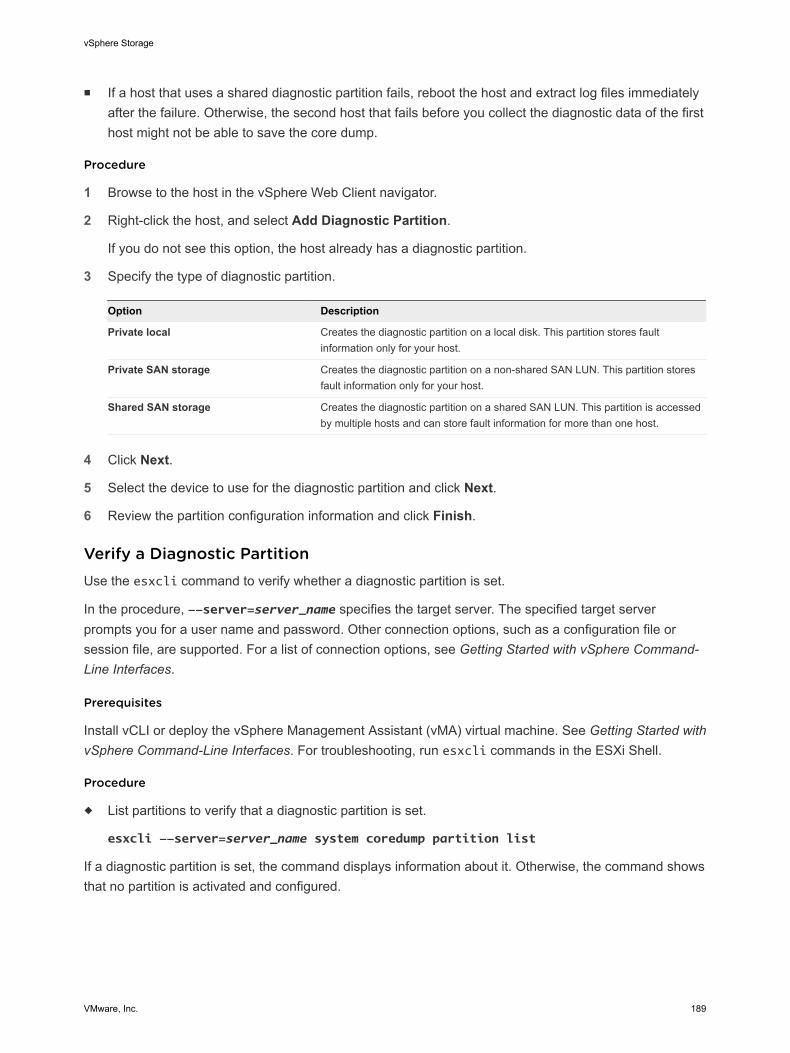
n If a host that uses a shared diagnostic partition fails, reboot the host and extract log files immediatelyafter the failure. Otherwise, the second host that fails before you collect the diagnostic data of the firsthost might not be able to save the core dump.
Procedure
1 Browse to the host in the vSphere Web Client navigator.
2 Right-click the host, and select Add Diagnostic Partition.
If you do not see this option, the host already has a diagnostic partition.
3 Specify the type of diagnostic partition.
Option Description
Private local Creates the diagnostic partition on a local disk. This partition stores faultinformation only for your host.
Private SAN storage Creates the diagnostic partition on a non-shared SAN LUN. This partition storesfault information only for your host.
Shared SAN storage Creates the diagnostic partition on a shared SAN LUN. This partition is accessedby multiple hosts and can store fault information for more than one host.
4 Click Next.
5 Select the device to use for the diagnostic partition and click Next.
6 Review the partition configuration information and click Finish.
Verify a Diagnostic PartitionUse the esxcli command to verify whether a diagnostic partition is set.
In the procedure, --server=server_name specifies the target server. The specified target serverprompts you for a user name and password. Other connection options, such as a configuration file orsession file, are supported. For a list of connection options, see Getting Started with vSphere Command-Line Interfaces.
Prerequisites
Install vCLI or deploy the vSphere Management Assistant (vMA) virtual machine. See Getting Started withvSphere Command-Line Interfaces. For troubleshooting, run esxcli commands in the ESXi Shell.
Procedure
u List partitions to verify that a diagnostic partition is set.
esxcli --server=server_name system coredump partition list
If a diagnostic partition is set, the command displays information about it. Otherwise, the command showsthat no partition is activated and configured.
vSphere Storage
VMware, Inc. 189
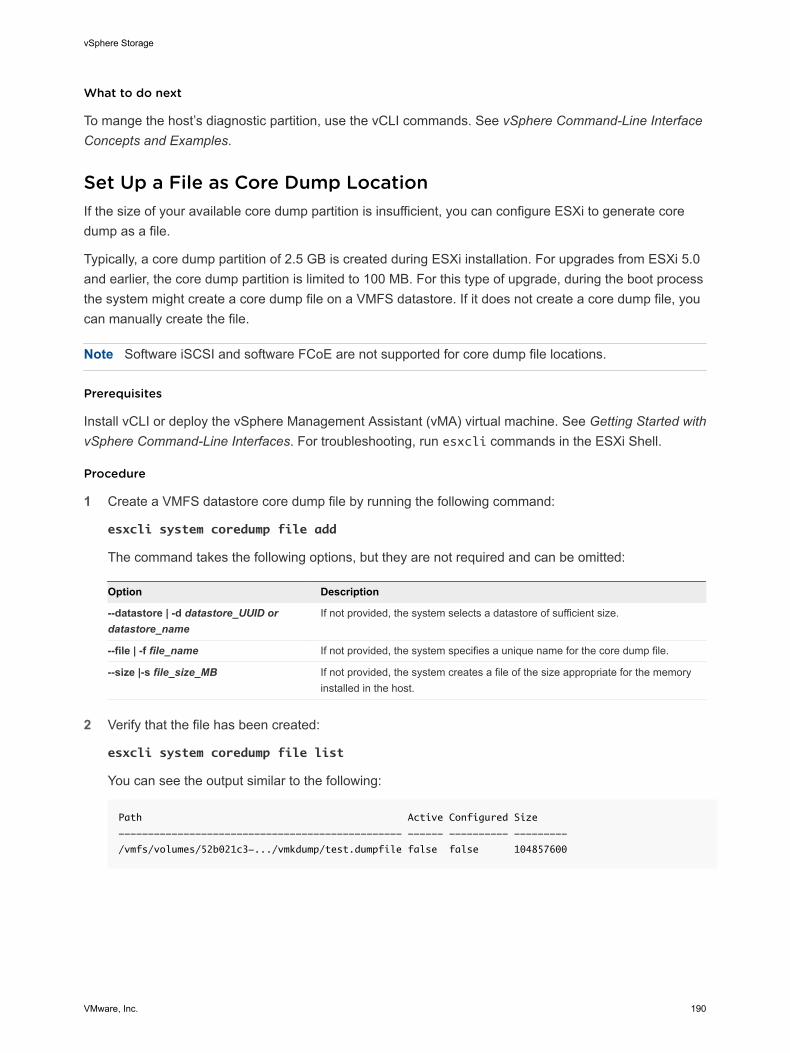
What to do next
To mange the host’s diagnostic partition, use the vCLI commands. See vSphere Command-Line InterfaceConcepts and Examples.
Set Up a File as Core Dump LocationIf the size of your available core dump partition is insufficient, you can configure ESXi to generate coredump as a file.
Typically, a core dump partition of 2.5 GB is created during ESXi installation. For upgrades from ESXi 5.0and earlier, the core dump partition is limited to 100 MB. For this type of upgrade, during the boot processthe system might create a core dump file on a VMFS datastore. If it does not create a core dump file, youcan manually create the file.
Note Software iSCSI and software FCoE are not supported for core dump file locations.
Prerequisites
Install vCLI or deploy the vSphere Management Assistant (vMA) virtual machine. See Getting Started withvSphere Command-Line Interfaces. For troubleshooting, run esxcli commands in the ESXi Shell.
Procedure
1 Create a VMFS datastore core dump file by running the following command:
esxcli system coredump file add
The command takes the following options, but they are not required and can be omitted:
Option Description
--datastore | -d datastore_UUID ordatastore_name
If not provided, the system selects a datastore of sufficient size.
--file | -f file_name If not provided, the system specifies a unique name for the core dump file.
--size |-s file_size_MB If not provided, the system creates a file of the size appropriate for the memoryinstalled in the host.
2 Verify that the file has been created:
esxcli system coredump file list
You can see the output similar to the following:
Path Active Configured Size
------------------------------------------------ ------ ---------- ---------
/vmfs/volumes/52b021c3-.../vmkdump/test.dumpfile false false 104857600
vSphere Storage
VMware, Inc. 190
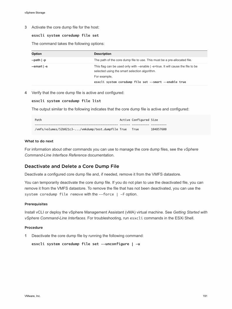
3 Activate the core dump file for the host:
esxcli system coredump file set
The command takes the following options:
Option Description
--path | -p The path of the core dump file to use. This must be a pre-allocated file.
--smart | -s This flag can be used only with --enable | -e=true. It will cause the file to beselected using the smart selection algorithm.
For example,
esxcli system coredump file set --smart --enable true
4 Verify that the core dump file is active and configured:
esxcli system coredump file list
The output similar to the following indicates that the core dump file is active and configured:
Path Active Configured Size
------------------------------------------------ ------ ---------- ---------
/vmfs/volumes/52b021c3-.../vmkdump/test.dumpfile True True 104857600
What to do next
For information about other commands you can use to manage the core dump files, see the vSphereCommand-Line Interface Reference documentation.
Deactivate and Delete a Core Dump FileDeactivate a configured core dump file and, if needed, remove it from the VMFS datastore.
You can temporarily deactivate the core dump file. If you do not plan to use the deactivated file, you canremove it from the VMFS datastore. To remove the file that has not been deactivated, you can use thesystem coredump file remove with the --force | -F option.
Prerequisites
Install vCLI or deploy the vSphere Management Assistant (vMA) virtual machine. See Getting Started withvSphere Command-Line Interfaces. For troubleshooting, run esxcli commands in the ESXi Shell.
Procedure
1 Deactivate the core dump file by running the following command:
esxcli system coredump file set --unconfigure | -u
vSphere Storage
VMware, Inc. 191
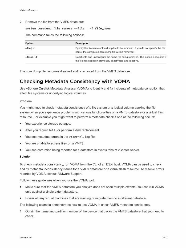
2 Remove the file from the VMFS datastore:
system coredump file remove --file | -f file_name
The command takes the following options:
Option Description
--file | -f Specify the file name of the dump file to be removed. If you do not specify the filename, the configured core dump file will be removed.
--force | -F Deactivate and unconfigure the dump file being removed. This option is required ifthe file has not been previously deactivated and is active.
The core dump file becomes disabled and is removed from the VMFS datastore.
Checking Metadata Consistency with VOMAUse vSphere On-disk Metadata Analyser (VOMA) to identify and fix incidents of metadata corruption thataffect file systems or underlying logical volumes.
Problem
You might need to check metadata consistency of a file system or a logical volume backing the filesystem when you experience problems with various functionalities on a VMFS datastore or a virtual flashresource. For example you might want to perform a metadata check if one of the following occurs:
n You experience storage outages.
n After you rebuild RAID or perform a disk replacement.
n You see metadata errors in the vmkernel.log file.
n You are unable to access files on a VMFS.
n You see corruption being reported for a datastore in events tabs of vCenter Server.
Solution
To check metadata consistency, run VOMA from the CLI of an ESXi host. VOMA can be used to checkand fix metadata inconsistency issues for a VMFS datastore or a virtual flash resource. To resolve errorsreported by VOMA, consult VMware Support.
Follow these guidelines when you use the VOMA tool:
n Make sure that the VMFS datastore you analyze does not span multiple extents. You can run VOMAonly against a single-extent datastore.
n Power off any virtual machines that are running or migrate them to a different datastore.
The following example demonstrates how to use VOMA to check VMFS metadata consistency.
1 Obtain the name and partition number of the device that backs the VMFS datastore that you need tocheck.
vSphere Storage
VMware, Inc. 192
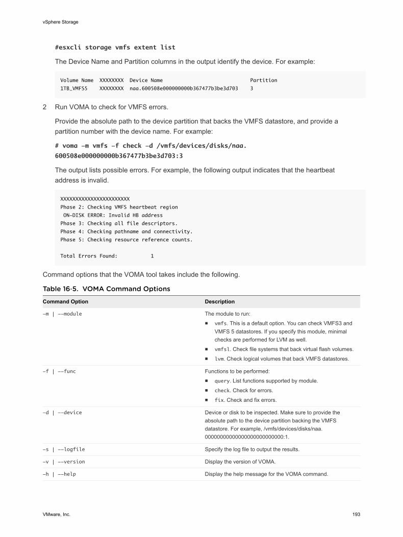
#esxcli storage vmfs extent list
The Device Name and Partition columns in the output identify the device. For example:
Volume Name XXXXXXXX Device Name Partition
1TB_VMFS5 XXXXXXXX naa.600508e000000000b367477b3be3d703 3
2 Run VOMA to check for VMFS errors.
Provide the absolute path to the device partition that backs the VMFS datastore, and provide apartition number with the device name. For example:
# voma -m vmfs -f check -d /vmfs/devices/disks/naa.
600508e000000000b367477b3be3d703:3
The output lists possible errors. For example, the following output indicates that the heartbeataddress is invalid.
XXXXXXXXXXXXXXXXXXXXXXX
Phase 2: Checking VMFS heartbeat region
ON-DISK ERROR: Invalid HB address
Phase 3: Checking all file descriptors.
Phase 4: Checking pathname and connectivity.
Phase 5: Checking resource reference counts.
Total Errors Found: 1
Command options that the VOMA tool takes include the following.
Table 16‑5. VOMA Command Options
Command Option Description
-m | --module The module to run:n vmfs. This is a default option. You can check VMFS3 and
VMFS 5 datastores. If you specify this module, minimalchecks are performed for LVM as well.
n vmfsl. Check file systems that back virtual flash volumes.n lvm. Check logical volumes that back VMFS datastores.
-f | --func Functions to be performed:n query. List functions supported by module.n check. Check for errors.n fix. Check and fix errors.
-d | --device Device or disk to be inspected. Make sure to provide theabsolute path to the device partition backing the VMFSdatastore. For example, /vmfs/devices/disks/naa.00000000000000000000000000:1.
-s | --logfile Specify the log file to output the results.
-v | --version Display the version of VOMA.
-h | --help Display the help message for the VOMA command.
vSphere Storage
VMware, Inc. 193
Configuring VMFS Pointer Block CacheYou can use advanced VMFS parameters to configure the pointer block cache.
As the size of the virtual machine files on the VMFS datastores increases, the number of pointer blocksused by those files also increases. The pointer blocks are used to address file blocks in the large virtualmachine files and virtual disks on the VMFS datastore.
You can configure the minimum and maximum sizes of the pointer block cache on each ESXi host. Whenthe size of the pointer block cache approaches the configured maximum size, an eviction mechanismremoves some pointer block entries from the cache.
Base the maximum size of the pointer block cache on the working size of all open virtual disk files thatreside on VMFS datastores. All VMFS datastores on the host use a single pointer block cache.
The minimum value is based on the minimum guaranteed memory that the system can allocate to thecache. 1 TB of open file space requires approximately 4 MB of memory.
To configure the minimum and maximum values for the pointer block cache, use the Advanced SystemSettings dialog box of the vSphere Web Client
Table 16‑6. Advanced Parameters to Regulate Pointer Block Cache
Parameter Values Description
VMFS3.MaxAddressableSpaceTB Default value is 32 (in TB). Maximum size of all open files that VMFScache supports before eviction starts.
VMFS3.MinAddressableSpaceTB Default value is 10 (in TB). Minimum size of all open files that VMFScache guarantees to support.
You can use the esxcli storage vmfs pbcache command to obtain information about the size of thepointer block cache and other statistics. This information assists you in adjusting minimum and maximumsizes of the pointer block cache, so that you can get maximum performance.
Set Advanced Host AttributesYou can set advanced attributes for a host.
Caution Changing advanced options is considered unsupported unless VMware technical support or aKB article instruct you to do so. In all other cases, changing these options is considered unsupported. Inmost cases, the default settings produce the optimum result.
Procedure
1 Browse to the host in the vSphere Web Client navigator.
2 Click the Manage tab and click Settings.
3 Under System, click Advanced System Settings.
4 In Advanced Settings, select the appropriate item.
vSphere Storage
VMware, Inc. 194
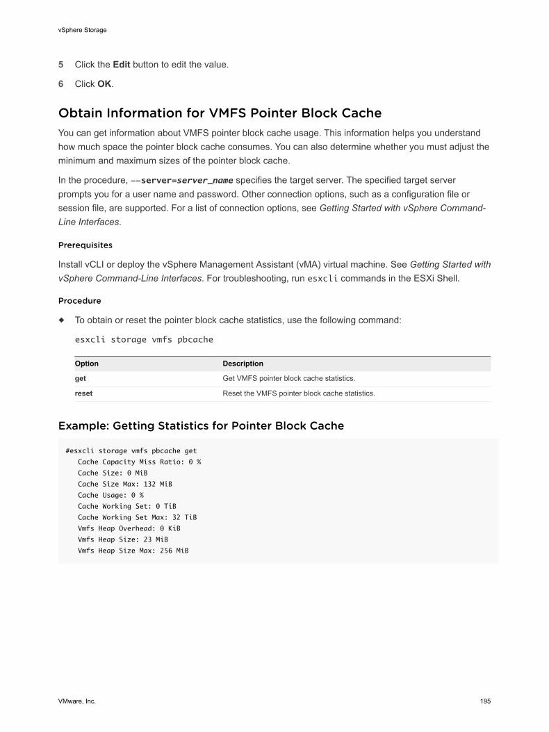
5 Click the Edit button to edit the value.
6 Click OK.
Obtain Information for VMFS Pointer Block CacheYou can get information about VMFS pointer block cache usage. This information helps you understandhow much space the pointer block cache consumes. You can also determine whether you must adjust theminimum and maximum sizes of the pointer block cache.
In the procedure, --server=server_name specifies the target server. The specified target serverprompts you for a user name and password. Other connection options, such as a configuration file orsession file, are supported. For a list of connection options, see Getting Started with vSphere Command-Line Interfaces.
Prerequisites
Install vCLI or deploy the vSphere Management Assistant (vMA) virtual machine. See Getting Started withvSphere Command-Line Interfaces. For troubleshooting, run esxcli commands in the ESXi Shell.
Procedure
u To obtain or reset the pointer block cache statistics, use the following command:
esxcli storage vmfs pbcache
Option Description
get Get VMFS pointer block cache statistics.
reset Reset the VMFS pointer block cache statistics.
Example: Getting Statistics for Pointer Block Cache
#esxcli storage vmfs pbcache get
Cache Capacity Miss Ratio: 0 %
Cache Size: 0 MiB
Cache Size Max: 132 MiB
Cache Usage: 0 %
Cache Working Set: 0 TiB
Cache Working Set Max: 32 TiB
Vmfs Heap Overhead: 0 KiB
Vmfs Heap Size: 23 MiB
Vmfs Heap Size Max: 256 MiB
vSphere Storage
VMware, Inc. 195
Understanding Multipathing andFailover 17To maintain a constant connection between a host and its storage, ESXi supports multipathing.Multipathing is a technique that lets you use more than one physical path that transfers data between thehost and an external storage device.
In case of a failure of any element in the SAN network, such as an adapter, switch, or cable, ESXi canswitch to another physical path, which does not use the failed component. This process of path switchingto avoid failed components is known as path failover.
In addition to path failover, multipathing provides load balancing. Load balancing is the process ofdistributing I/O loads across multiple physical paths. Load balancing reduces or removes potentialbottlenecks.
Note Virtual machine I/O might be delayed for up to sixty seconds while path failover takes place. Thesedelays allow the SAN to stabilize its configuration after topology changes. In general, the I/O delays mightbe longer on active-passive arrays and shorter on active-active arrays.
This chapter includes the following topics:
n Failover with Fibre Channel
n Host-Based Failover with iSCSI
n Array-Based Failover with iSCSI
n Path Failover and Virtual Machines
n Managing Multiple Paths
n VMware Multipathing Module
n Path Scanning and Claiming
n Managing Storage Paths and Multipathing Plug-Ins
n Scheduling Queues for Virtual Machine I/Os
Failover with Fibre ChannelTo support multipathing, your host typically has two or more HBAs available. This configurationsupplements the SAN multipathing configuration that generally provides one or more switches in the SANfabric and one or more storage processors on the storage array device itself.
VMware, Inc. 196
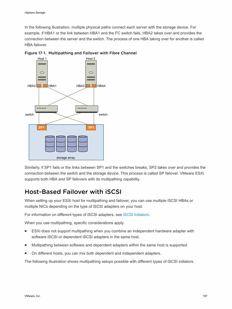
In the following illustration, multiple physical paths connect each server with the storage device. Forexample, if HBA1 or the link between HBA1 and the FC switch fails, HBA2 takes over and provides theconnection between the server and the switch. The process of one HBA taking over for another is calledHBA failover.
Figure 17‑1. Multipathing and Failover with Fibre Channel
SP2
storage array
SP1
switch switch
HBA2 HBA1 HBA3 HBA4
Host 1 Host 2
Similarly, if SP1 fails or the links between SP1 and the switches breaks, SP2 takes over and provides theconnection between the switch and the storage device. This process is called SP failover. VMware ESXisupports both HBA and SP failovers with its multipathing capability.
Host-Based Failover with iSCSIWhen setting up your ESXi host for multipathing and failover, you can use multiple iSCSI HBAs ormultiple NICs depending on the type of iSCSI adapters on your host.
For information on different types of iSCSI adapters, see iSCSI Initiators.
When you use multipathing, specific considerations apply.
n ESXi does not support multipathing when you combine an independent hardware adapter withsoftware iSCSI or dependent iSCSI adapters in the same host.
n Multipathing between software and dependent adapters within the same host is supported.
n On different hosts, you can mix both dependent and independent adapters.
The following illustration shows multipathing setups possible with different types of iSCSI initiators.
vSphere Storage
VMware, Inc. 197
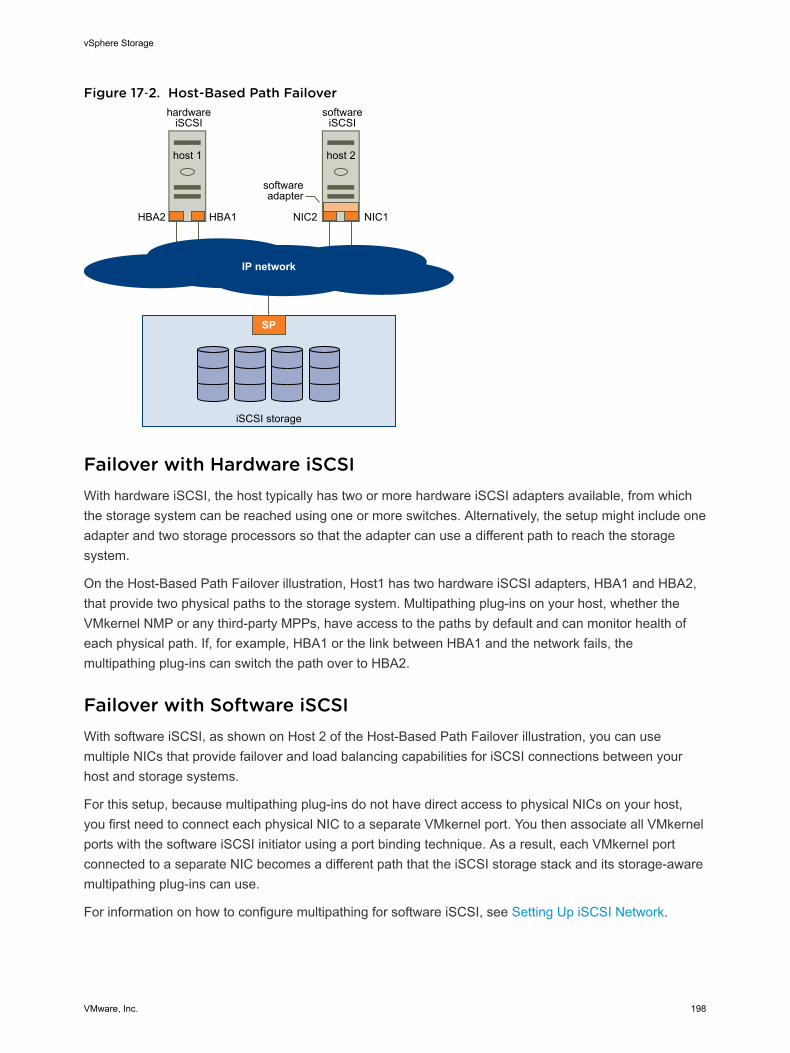
Figure 17‑2. Host-Based Path Failover
IP network
hardwareiSCSI
host 1
SP
iSCSI storage
HBA2 HBA1
softwareiSCSI
host 2
NIC2 NIC1
softwareadapter
Failover with Hardware iSCSIWith hardware iSCSI, the host typically has two or more hardware iSCSI adapters available, from whichthe storage system can be reached using one or more switches. Alternatively, the setup might include oneadapter and two storage processors so that the adapter can use a different path to reach the storagesystem.
On the Host-Based Path Failover illustration, Host1 has two hardware iSCSI adapters, HBA1 and HBA2,that provide two physical paths to the storage system. Multipathing plug-ins on your host, whether theVMkernel NMP or any third-party MPPs, have access to the paths by default and can monitor health ofeach physical path. If, for example, HBA1 or the link between HBA1 and the network fails, themultipathing plug-ins can switch the path over to HBA2.
Failover with Software iSCSIWith software iSCSI, as shown on Host 2 of the Host-Based Path Failover illustration, you can usemultiple NICs that provide failover and load balancing capabilities for iSCSI connections between yourhost and storage systems.
For this setup, because multipathing plug-ins do not have direct access to physical NICs on your host,you first need to connect each physical NIC to a separate VMkernel port. You then associate all VMkernelports with the software iSCSI initiator using a port binding technique. As a result, each VMkernel portconnected to a separate NIC becomes a different path that the iSCSI storage stack and its storage-awaremultipathing plug-ins can use.
For information on how to configure multipathing for software iSCSI, see Setting Up iSCSI Network.
vSphere Storage
VMware, Inc. 198
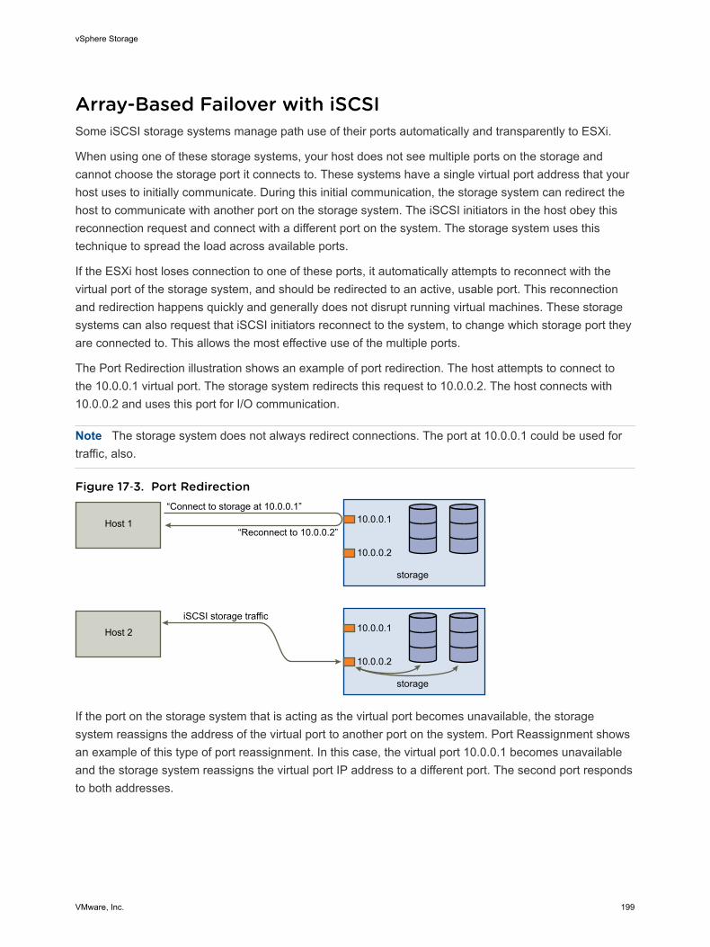
Array-Based Failover with iSCSISome iSCSI storage systems manage path use of their ports automatically and transparently to ESXi.
When using one of these storage systems, your host does not see multiple ports on the storage andcannot choose the storage port it connects to. These systems have a single virtual port address that yourhost uses to initially communicate. During this initial communication, the storage system can redirect thehost to communicate with another port on the storage system. The iSCSI initiators in the host obey thisreconnection request and connect with a different port on the system. The storage system uses thistechnique to spread the load across available ports.
If the ESXi host loses connection to one of these ports, it automatically attempts to reconnect with thevirtual port of the storage system, and should be redirected to an active, usable port. This reconnectionand redirection happens quickly and generally does not disrupt running virtual machines. These storagesystems can also request that iSCSI initiators reconnect to the system, to change which storage port theyare connected to. This allows the most effective use of the multiple ports.
The Port Redirection illustration shows an example of port redirection. The host attempts to connect tothe 10.0.0.1 virtual port. The storage system redirects this request to 10.0.0.2. The host connects with10.0.0.2 and uses this port for I/O communication.
Note The storage system does not always redirect connections. The port at 10.0.0.1 could be used fortraffic, also.
Figure 17‑3. Port Redirection
storage
10.0.0.1
10.0.0.2
Host 1
“Connect to storage at 10.0.0.1”
“Reconnect to 10.0.0.2”
storage
10.0.0.1
10.0.0.2
Host 2
iSCSI storage traffic
If the port on the storage system that is acting as the virtual port becomes unavailable, the storagesystem reassigns the address of the virtual port to another port on the system. Port Reassignment showsan example of this type of port reassignment. In this case, the virtual port 10.0.0.1 becomes unavailableand the storage system reassigns the virtual port IP address to a different port. The second port respondsto both addresses.
vSphere Storage
VMware, Inc. 199
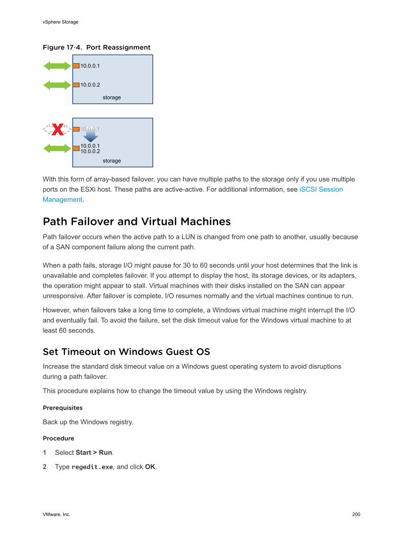
Figure 17‑4. Port Reassignment
storage
10.0.0.1
10.0.0.2
storage
10.0.0.1
10.0.0.110.0.0.2
With this form of array-based failover, you can have multiple paths to the storage only if you use multipleports on the ESXi host. These paths are active-active. For additional information, see iSCSI SessionManagement.
Path Failover and Virtual MachinesPath failover occurs when the active path to a LUN is changed from one path to another, usually becauseof a SAN component failure along the current path.
When a path fails, storage I/O might pause for 30 to 60 seconds until your host determines that the link isunavailable and completes failover. If you attempt to display the host, its storage devices, or its adapters,the operation might appear to stall. Virtual machines with their disks installed on the SAN can appearunresponsive. After failover is complete, I/O resumes normally and the virtual machines continue to run.
However, when failovers take a long time to complete, a Windows virtual machine might interrupt the I/Oand eventually fail. To avoid the failure, set the disk timeout value for the Windows virtual machine to atleast 60 seconds.
Set Timeout on Windows Guest OSIncrease the standard disk timeout value on a Windows guest operating system to avoid disruptionsduring a path failover.
This procedure explains how to change the timeout value by using the Windows registry.
Prerequisites
Back up the Windows registry.
Procedure
1 Select Start > Run.
2 Type regedit.exe, and click OK.
vSphere Storage
VMware, Inc. 200
3 In the left-panel hierarchy view, double-click HKEY_LOCAL_MACHINE > System >CurrentControlSet > Services > Disk.
4 Double-click TimeOutValue.
5 Set the value data to 0x3c (hexadecimal) or 60 (decimal) and click OK.
After you make this change, Windows waits at least 60 seconds for delayed disk operations tocomplete before it generates errors.
6 Reboot guest OS for the change to take effect.
Managing Multiple PathsTo manage storage multipathing, ESXi uses a collection of Storage APIs, also called the PluggableStorage Architecture (PSA). The PSA is an open, modular framework that coordinates the simultaneousoperation of multiple multipathing plug-ins (MPPs). The PSA allows 3rd party software developers todesign their own load balancing techniques and failover mechanisms for particular storage array, andinsert their code directly into the ESXi storage I/O path.
Topics discussing path management use the following acronyms.
Table 17‑1. Multipathing Acronyms
Acronym Definition
PSA Pluggable Storage Architecture
NMP Native Multipathing Plug-In. Generic VMware multipathingmodule.
PSP Path Selection Plug-In, also called Path Selection Policy.Handles path selection for a given device.
SATP Storage Array Type Plug-In, also called Storage Array TypePolicy. Handles path failover for a given storage array.
The VMkernel multipathing plug-in that ESXi provides by default is the VMware Native Multipathing Plug-In (NMP). The NMP is an extensible module that manages sub plug-ins. There are two types of NMP subplug-ins, Storage Array Type Plug-Ins (SATPs), and Path Selection Plug-Ins (PSPs). SATPs and PSPscan be built-in and provided by VMware, or can be provided by a third party.
If more multipathing functionality is required, a third party can also provide an MPP to run in addition to, oras a replacement for, the default NMP.
When coordinating the VMware NMP and any installed third-party MPPs, the PSA performs the followingtasks:
n Loads and unloads multipathing plug-ins.
n Hides virtual machine specifics from a particular plug-in.
n Routes I/O requests for a specific logical device to the MPP managing that device.
n Handles I/O queueing to the logical devices.
n Implements logical device bandwidth sharing between virtual machines.
vSphere Storage
VMware, Inc. 201
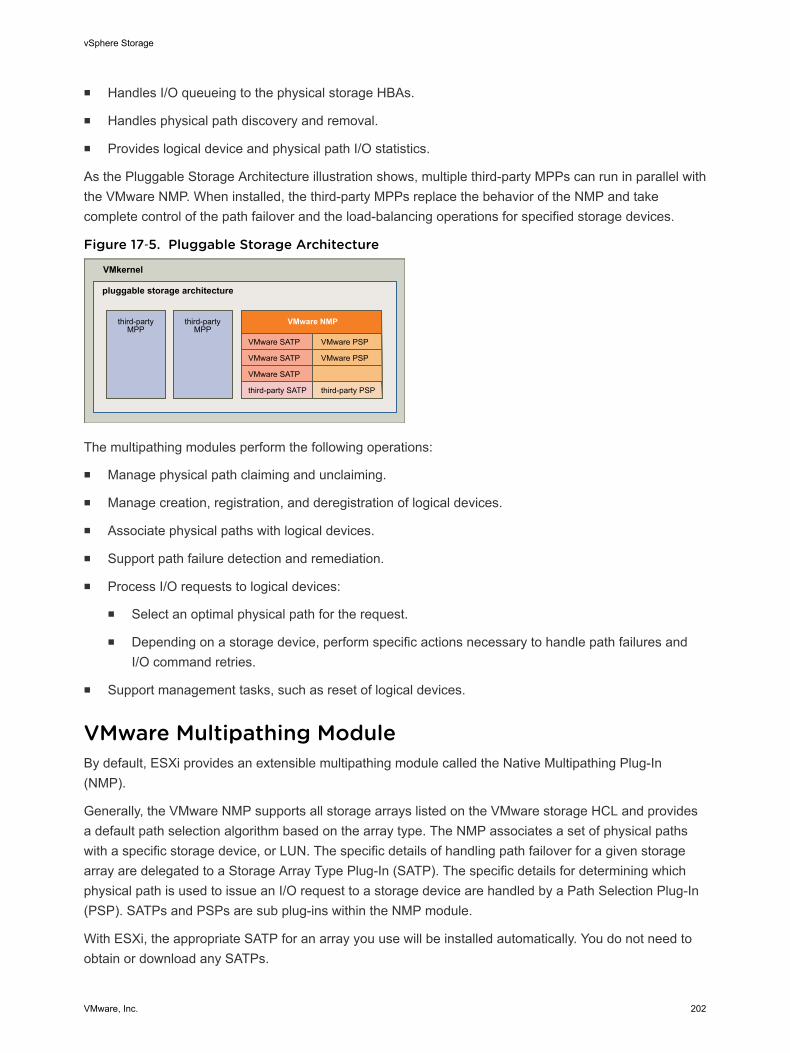
n Handles I/O queueing to the physical storage HBAs.
n Handles physical path discovery and removal.
n Provides logical device and physical path I/O statistics.
As the Pluggable Storage Architecture illustration shows, multiple third-party MPPs can run in parallel withthe VMware NMP. When installed, the third-party MPPs replace the behavior of the NMP and takecomplete control of the path failover and the load-balancing operations for specified storage devices.
Figure 17‑5. Pluggable Storage Architecture
third-partyMPP
third-partyMPP
VMkernel
pluggable storage architecture
VMware NMP
VMware SATP VMware PSP
VMware SATP VMware PSP
VMware SATP
third-party SATP third-party PSP
The multipathing modules perform the following operations:
n Manage physical path claiming and unclaiming.
n Manage creation, registration, and deregistration of logical devices.
n Associate physical paths with logical devices.
n Support path failure detection and remediation.
n Process I/O requests to logical devices:
n Select an optimal physical path for the request.
n Depending on a storage device, perform specific actions necessary to handle path failures andI/O command retries.
n Support management tasks, such as reset of logical devices.
VMware Multipathing ModuleBy default, ESXi provides an extensible multipathing module called the Native Multipathing Plug-In(NMP).
Generally, the VMware NMP supports all storage arrays listed on the VMware storage HCL and providesa default path selection algorithm based on the array type. The NMP associates a set of physical pathswith a specific storage device, or LUN. The specific details of handling path failover for a given storagearray are delegated to a Storage Array Type Plug-In (SATP). The specific details for determining whichphysical path is used to issue an I/O request to a storage device are handled by a Path Selection Plug-In(PSP). SATPs and PSPs are sub plug-ins within the NMP module.
With ESXi, the appropriate SATP for an array you use will be installed automatically. You do not need toobtain or download any SATPs.
vSphere Storage
VMware, Inc. 202
VMware SATPsStorage Array Type Plug-Ins (SATPs) run in conjunction with the VMware NMP and are responsible forarray-specific operations.
ESXi offers a SATP for every type of array that VMware supports. It also provides default SATPs thatsupport non-specific active-active and ALUA storage arrays, and the local SATP for direct-attacheddevices. Each SATP accommodates special characteristics of a certain class of storage arrays and canperform the array-specific operations required to detect path state and to activate an inactive path. As aresult, the NMP module itself can work with multiple storage arrays without having to be aware of thestorage device specifics.
After the NMP determines which SATP to use for a specific storage device and associates the SATP withthe physical paths for that storage device, the SATP implements the tasks that include the following:
n Monitors the health of each physical path.
n Reports changes in the state of each physical path.
n Performs array-specific actions necessary for storage fail-over. For example, for active-passivedevices, it can activate passive paths.
VMware PSPsPath Selection Plug-Ins (PSPs) are sub plug-ins of the VMware NMP and are responsible for choosing aphysical path for I/O requests.
The VMware NMP assigns a default PSP for each logical device based on the SATP associated with thephysical paths for that device. You can override the default PSP. For information, see Path Scanning andClaiming.
By default, the VMware NMP supports the following PSPs:
VMW_PSP_MRU The host selects the path that it used most recently. When the pathbecomes unavailable, the host selects an alternative path. The host doesnot revert back to the original path when that path becomes availableagain. There is no preferred path setting with the MRU policy. MRU is thedefault policy for most active-passive storage devices.
The VMW_PSP_MRU ranking capability allows you to assign ranks toindividual paths. To set ranks to individual paths, use the esxcli storagenmp psp generic pathconfig set command. For details, see theVMware knowledge base article at http://kb.vmware.com/kb/2003468.
vSphere Storage
VMware, Inc. 203
The policy is displayed in the client as the Most Recently Used (VMware)path selection policy.
VMW_PSP_FIXED The host uses the designated preferred path, if it has been configured.Otherwise, it selects the first working path discovered at system boot time.If you want the host to use a particular preferred path, specify it manually.Fixed is the default policy for most active-active storage devices.
Note If the host uses a default preferred path and the path's status turnsto Dead, a new path is selected as preferred. However, if you explicitlydesignate the preferred path, it will remain preferred even when it becomesinaccessible.
Displayed in the client as the Fixed (VMware) path selection policy.
VMW_PSP_RR The host uses an automatic path selection algorithm rotating through allactive paths when connecting to active-passive arrays, or through allavailable paths when connecting to active-active arrays. RR is the defaultfor a number of arrays and can be used with both active-active and active-passive arrays to implement load balancing across paths for different LUNs.
Displayed in the client as the Round Robin (VMware) path selection policy.
VMware NMP Flow of I/OWhen a virtual machine issues an I/O request to a storage device managed by the NMP, the followingprocess takes place.
1 The NMP calls the PSP assigned to this storage device.
2 The PSP selects an appropriate physical path on which to issue the I/O.
3 The NMP issues the I/O request on the path selected by the PSP.
4 If the I/O operation is successful, the NMP reports its completion.
5 If the I/O operation reports an error, the NMP calls the appropriate SATP.
6 The SATP interprets the I/O command errors and, when appropriate, activates the inactive paths.
7 The PSP is called to select a new path on which to issue the I/O.
Path Scanning and ClaimingWhen you start your ESXi host or rescan your storage adapter, the host discovers all physical paths tostorage devices available to the host. Based on a set of claim rules, the host determines whichmultipathing plug-in (MPP) should claim the paths to a particular device and become responsible formanaging the multipathing support for the device.
By default, the host performs a periodic path evaluation every 5 minutes causing any unclaimed paths tobe claimed by the appropriate MPP.
vSphere Storage
VMware, Inc. 204
The claim rules are numbered. For each physical path, the host runs through the claim rules starting withthe lowest number first. The attributes of the physical path are compared to the path specification in theclaim rule. If there is a match, the host assigns the MPP specified in the claim rule to manage the physicalpath. This continues until all physical paths are claimed by corresponding MPPs, either third-partymultipathing plug-ins or the native multipathing plug-in (NMP).
For the paths managed by the NMP module, a second set of claim rules is applied. These rulesdetermine which Storage Array Type Plug-In (SATP) should be used to manage the paths for a specificarray type, and which Path Selection Plug-In (PSP) is to be used for each storage device.
Use the vSphere Web Client to view which SATP and PSP the host is using for a specific storage deviceand the status of all available paths for this storage device. If needed, you can change the defaultVMware PSP using the client. To change the default SATP, you need to modify claim rules using thevSphere CLI.
You can find some information about modifying claim rules in Managing Storage Paths and MultipathingPlug-Ins.
For more information about the commands available to manage PSA, see Getting Started with vSphereCommand-Line Interfaces.
For a complete list of storage arrays and corresponding SATPs and PSPs, see the SAN Array ModelReference section of the vSphere Compatibility Guide.
Viewing the Paths InformationYou can review the storage array type policy (SATP) and path selection policy (PSP) that the ESXi hostuses for a specific storage device and the status of all available paths for this storage device. You canaccess the path information from both the Datastores and Devices views. For datastores, you review thepaths that connect to the device the datastore is deployed on.
The path information includes the SATP assigned to manage the device, the PSP, a list of paths, and thestatus of each path. The following path status information can appear:
Active Paths available for issuing I/O to a LUN. A single or multiple working pathscurrently used for transferring data are marked as Active (I/O).
Standby If active paths fail, the path can quickly become operational and can beused for I/O.
Disabled The path is disabled and no data can be transferred.
Dead The software cannot connect to the disk through this path.
If you are using the Fixed path policy, you can see which path is the preferred path. The preferred path ismarked with an asterisk (*) in the Preferred column.
For each path you can also display the path's name. The name includes parameters that describe thepath: adapter ID, target ID, and device ID. Usually, the path's name has the format similar to the following:
vSphere Storage
VMware, Inc. 205
fc.adapterID-fc.targetID-naa.deviceID
Note When you use the host profiles editor to edit paths, you must specify all three parameters thatdescribe a path, adapter ID, target ID, and device ID.
View Datastore PathsReview the paths that connect to storage devices backing your datastores.
Procedure
1 In the vSphere Web Client navigator, select vCenter Inventory Lists > Datastores
2 Click the datastore to display its information.
3 Click the Manage tab, and click Settings.
4 Click Connectivity and Multipathing.
5 If the datastore is shared, select a host to view multipathing details for its devices.
6 Under Multipathing Details, review the multipathing policies and paths for the storage device thatbacks your datastore.
View Storage Device PathsView which multipathing policies the host uses for a specific storage device and the status of all availablepaths for this storage device.
Procedure
1 Browse to the host in the vSphere Web Client navigator.
2 Click the Manage tab, and click Storage.
3 Click Storage Devices.
4 Select the storage device whose paths you want to view.
5 Click the Properties tab and review details under Multipathing Policies.
6 Click the Paths tab to review all paths available for the storage device.
Setting a Path Selection PolicyFor each storage device, the ESXi host sets the path selection policy based on the claim rules.
vSphere Storage
VMware, Inc. 206
By default, VMware supports the following path selection policies. If you have a third-party PSP installedon your host, its policy also appears on the list.
Fixed (VMware) The host uses the designated preferred path, if it has been configured.Otherwise, it selects the first working path discovered at system boot time.If you want the host to use a particular preferred path, specify it manually.Fixed is the default policy for most active-active storage devices.
Note If the host uses a default preferred path and the path's status turnsto Dead, a new path is selected as preferred. However, if you explicitlydesignate the preferred path, it will remain preferred even when it becomesinaccessible.
Most Recently Used(VMware)
The host selects the path that it used most recently. When the pathbecomes unavailable, the host selects an alternative path. The host doesnot revert back to the original path when that path becomes availableagain. There is no preferred path setting with the MRU policy. MRU is thedefault policy for most active-passive storage devices.
Round Robin (VMware) The host uses an automatic path selection algorithm rotating through allactive paths when connecting to active-passive arrays, or through allavailable paths when connecting to active-active arrays. RR is the defaultfor a number of arrays and can be used with both active-active and active-passive arrays to implement load balancing across paths for different LUNs.
Change the Path Selection PolicyGenerally, you do not need to change the default multipathing settings your host uses for a specificstorage device. However, if you want to make any changes, you can use the Edit Multipathing Policiesdialog box to modify a path selection policy and specify the preferred path for the Fixed policy. You canalso use this dialog box to change multipathing for SCSI-based protocol endpoints.
Procedure
1 Browse to the host in the vSphere Web Client navigator.
2 Click the Manage tab, and click Storage.
3 Click Storage Devices or Protocol Endpoints.
4 Select the item whose paths you want to change and click the Properties tab.
5 Under Multipathing Policies, click Edit Multipathing.
vSphere Storage
VMware, Inc. 207
6 Select a path policy.
By default, VMware supports the following path selection policies. If you have a third-party PSPinstalled on your host, its policy also appears on the list.
n Fixed (VMware)
n Most Recently Used (VMware)
n Round Robin (VMware)
7 For the fixed policy, specify the preferred path.
8 Click OK to save your settings and exit the dialog box.
Disable Storage PathsYou can temporarily disable paths for maintenance or other reasons.
You disable a path using the Paths panel. You have several ways to access the Paths panel, from adatastore, a storage device, or an adapter view. This task explains how to disable a path using a storagedevice view.
Procedure
1 Browse to the host in the vSphere Web Client navigator.
2 Click the Manage tab, and click Storage.
3 Click Storage Devices.
4 Select the storage device whose paths you want to disable and click the Paths tab.
5 Select the path to disable and click Disable.
Managing Storage Paths and Multipathing Plug-InsUse the esxcli commands to manage the PSA multipathing plug-ins and storage paths assigned tothem.
You can display all multipathing plug-ins available on your host. You can list any third-party MPPs, as wellas your host's NMP and SATPs and review the paths they claim. You can also define new paths andspecify which multipathing plug-in should claim the paths.
For more information about commands available to manage PSA, see the Getting Started with vSphereCommand-Line Interfaces.
Multipathing ConsiderationsSpecific considerations apply when you manage storage multipathing plug-ins and claim rules.
The following considerations help you with multipathing:
n If no SATP is assigned to the device by the claim rules, the default SATP for iSCSI or FC devices isVMW_SATP_DEFAULT_AA. The default PSP is VMW_PSP_FIXED.
vSphere Storage
VMware, Inc. 208
n When the system searches the SATP rules to locate a SATP for a given device, it searches the driverrules first. If there is no match, the vendor/model rules are searched, and finally the transport rulesare searched. If no match occurs, NMP selects a default SATP for the device.
n If VMW_SATP_ALUA is assigned to a specific storage device, but the device is not ALUA-aware, noclaim rule match occurs for this device. The device is claimed by the default SATP based on thedevice's transport type.
n The default PSP for all devices claimed by VMW_SATP_ALUA is VMW_PSP_MRU. TheVMW_PSP_MRU selects an active/optimized path as reported by the VMW_SATP_ALUA, or anactive/unoptimized path if there is no active/optimized path. This path is used until a better path isavailable (MRU). For example, if the VMW_PSP_MRU is currently using an active/unoptimized pathand an active/optimized path becomes available, the VMW_PSP_MRU will switch the current path tothe active/optimized one.
n While VMW_PSP_MRU is typically selected for ALUA arrays by default, certain ALUA storage arraysneed to use VMW_PSP_FIXED. To check whether your storage array requires VMW_PSP_FIXED,see the VMware Compatibility Guide or contact your storage vendor. When using VMW_PSP_FIXEDwith ALUA arrays, unless you explicitly specify a preferred path, the ESXi host selects the mostoptimal working path and designates it as the default preferred path. If the host selected pathbecomes unavailable, the host selects an alternative available path. However, if you explicitlydesignate the preferred path, it will remain preferred no matter what its status is.
n By default, the PSA claim rule 101 masks Dell array pseudo devices. Do not delete this rule, unlessyou want to unmask these devices.
List Multipathing Claim Rules for the HostUse the esxcli command to list available multipathing claim rules.
Claim rules indicate which multipathing plug-in, the NMP or any third-party MPP, manages a givenphysical path. Each claim rule identifies a set of paths based on the following parameters:
n Vendor/model strings
n Transportation, such as SATA, IDE, Fibre Channel, and so on
n Adapter, target, or LUN location
n Device driver, for example, Mega-RAID
In the procedure, --server=server_name specifies the target server. The specified target serverprompts you for a user name and password. Other connection options, such as a configuration file orsession file, are supported. For a list of connection options, see Getting Started with vSphere Command-Line Interfaces.
Prerequisites
Install vCLI or deploy the vSphere Management Assistant (vMA) virtual machine. See Getting Started withvSphere Command-Line Interfaces. For troubleshooting, run esxcli commands in the ESXi Shell.
vSphere Storage
VMware, Inc. 209
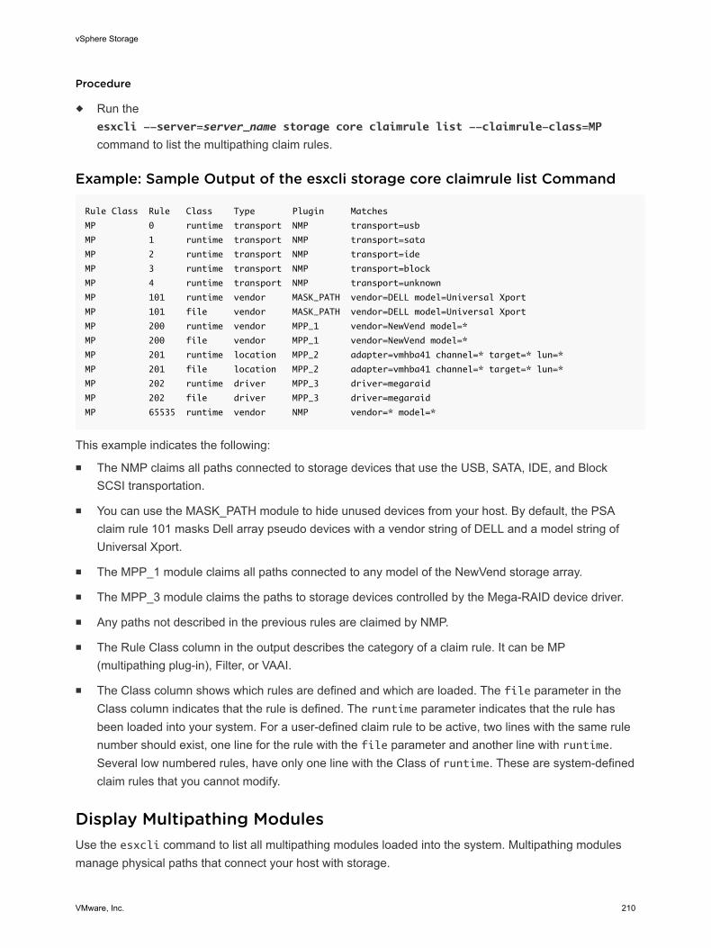
Procedure
u Run theesxcli --server=server_name storage core claimrule list --claimrule-class=MP
command to list the multipathing claim rules.
Example: Sample Output of the esxcli storage core claimrule list Command
Rule Class Rule Class Type Plugin Matches
MP 0 runtime transport NMP transport=usb
MP 1 runtime transport NMP transport=sata
MP 2 runtime transport NMP transport=ide
MP 3 runtime transport NMP transport=block
MP 4 runtime transport NMP transport=unknown
MP 101 runtime vendor MASK_PATH vendor=DELL model=Universal Xport
MP 101 file vendor MASK_PATH vendor=DELL model=Universal Xport
MP 200 runtime vendor MPP_1 vendor=NewVend model=*
MP 200 file vendor MPP_1 vendor=NewVend model=*
MP 201 runtime location MPP_2 adapter=vmhba41 channel=* target=* lun=*
MP 201 file location MPP_2 adapter=vmhba41 channel=* target=* lun=*
MP 202 runtime driver MPP_3 driver=megaraid
MP 202 file driver MPP_3 driver=megaraid
MP 65535 runtime vendor NMP vendor=* model=*
This example indicates the following:
n The NMP claims all paths connected to storage devices that use the USB, SATA, IDE, and BlockSCSI transportation.
n You can use the MASK_PATH module to hide unused devices from your host. By default, the PSAclaim rule 101 masks Dell array pseudo devices with a vendor string of DELL and a model string ofUniversal Xport.
n The MPP_1 module claims all paths connected to any model of the NewVend storage array.
n The MPP_3 module claims the paths to storage devices controlled by the Mega-RAID device driver.
n Any paths not described in the previous rules are claimed by NMP.
n The Rule Class column in the output describes the category of a claim rule. It can be MP(multipathing plug-in), Filter, or VAAI.
n The Class column shows which rules are defined and which are loaded. The file parameter in theClass column indicates that the rule is defined. The runtime parameter indicates that the rule hasbeen loaded into your system. For a user-defined claim rule to be active, two lines with the same rulenumber should exist, one line for the rule with the file parameter and another line with runtime.Several low numbered rules, have only one line with the Class of runtime. These are system-definedclaim rules that you cannot modify.
Display Multipathing ModulesUse the esxcli command to list all multipathing modules loaded into the system. Multipathing modulesmanage physical paths that connect your host with storage.
vSphere Storage
VMware, Inc. 210
In the procedure, --server=server_name specifies the target server. The specified target serverprompts you for a user name and password. Other connection options, such as a configuration file orsession file, are supported. For a list of connection options, see Getting Started with vSphere Command-Line Interfaces.
Prerequisites
Install vCLI or deploy the vSphere Management Assistant (vMA) virtual machine. See Getting Started withvSphere Command-Line Interfaces. For troubleshooting, run esxcli commands in the ESXi Shell.
Procedure
u To list multipathing modules, run the following command:
esxcli --server=server_name storage core plugin list --plugin-class=MP
This command typically shows the NMP and, if loaded, the MASK_PATH module. If any third-party MPPshave been loaded, they are listed as well.
Display SATPs for the HostUse the esxcli command to list VMware NMP SATPs loaded into the system. Display information aboutthe SATPs.
In the procedure, --server=server_name specifies the target server. The specified target serverprompts you for a user name and password. Other connection options, such as a configuration file orsession file, are supported. For a list of connection options, see Getting Started with vSphere Command-Line Interfaces.
Prerequisites
Install vCLI or deploy the vSphere Management Assistant (vMA) virtual machine. See Getting Started withvSphere Command-Line Interfaces. For troubleshooting, run esxcli commands in the ESXi Shell.
Procedure
u To list VMware SATPs, run the following command:
esxcli --server=server_name storage nmp satp list
For each SATP, the output displays information that shows the type of storage array or system this SATPsupports and the default PSP for any LUNs using this SATP. Placeholder (plugin not loaded) in theDescription column indicates that the SATP is not loaded.
Display NMP Storage DevicesUse the esxcli command to list all storage devices controlled by the VMware NMP and display SATPand PSP information associated with each device.
vSphere Storage
VMware, Inc. 211
In the procedure, --server=server_name specifies the target server. The specified target serverprompts you for a user name and password. Other connection options, such as a configuration file orsession file, are supported. For a list of connection options, see Getting Started with vSphere Command-Line Interfaces.
Prerequisites
Install vCLI or deploy the vSphere Management Assistant (vMA) virtual machine. See Getting Started withvSphere Command-Line Interfaces. For troubleshooting, run esxcli commands in the ESXi Shell.
Procedure
u To list all storage devices, run the following command:
esxcli --server=server_name storage nmp device list
Use the --device | -d=device_ID option to filter the output of this command to show a singledevice.
Add Multipathing Claim RulesUse the esxcli commands to add a new multipathing PSA claim rule to the set of claim rules on thesystem. For the new claim rule to be active, you first define the rule and then load it into your system.
You add a new PSA claim rule when, for example, you load a new multipathing plug-in (MPP) and need todefine which paths this module should claim. You may need to create a claim rule if you add new pathsand want an existing MPP to claim them.
Caution When creating new claim rules, be careful to avoid a situation where different physical paths tothe same LUN are claimed by different MPPs. Unless one of the MPPs is the MASK_PATH MPP, thisconfiguration will cause performance problems.
In the procedure, --server=server_name specifies the target server. The specified target serverprompts you for a user name and password. Other connection options, such as a configuration file orsession file, are supported. For a list of connection options, see Getting Started with vSphere Command-Line Interfaces.
Prerequisites
Install vCLI or deploy the vSphere Management Assistant (vMA) virtual machine. See Getting Started withvSphere Command-Line Interfaces. For troubleshooting, run esxcli commands in the ESXi Shell.
vSphere Storage
VMware, Inc. 212
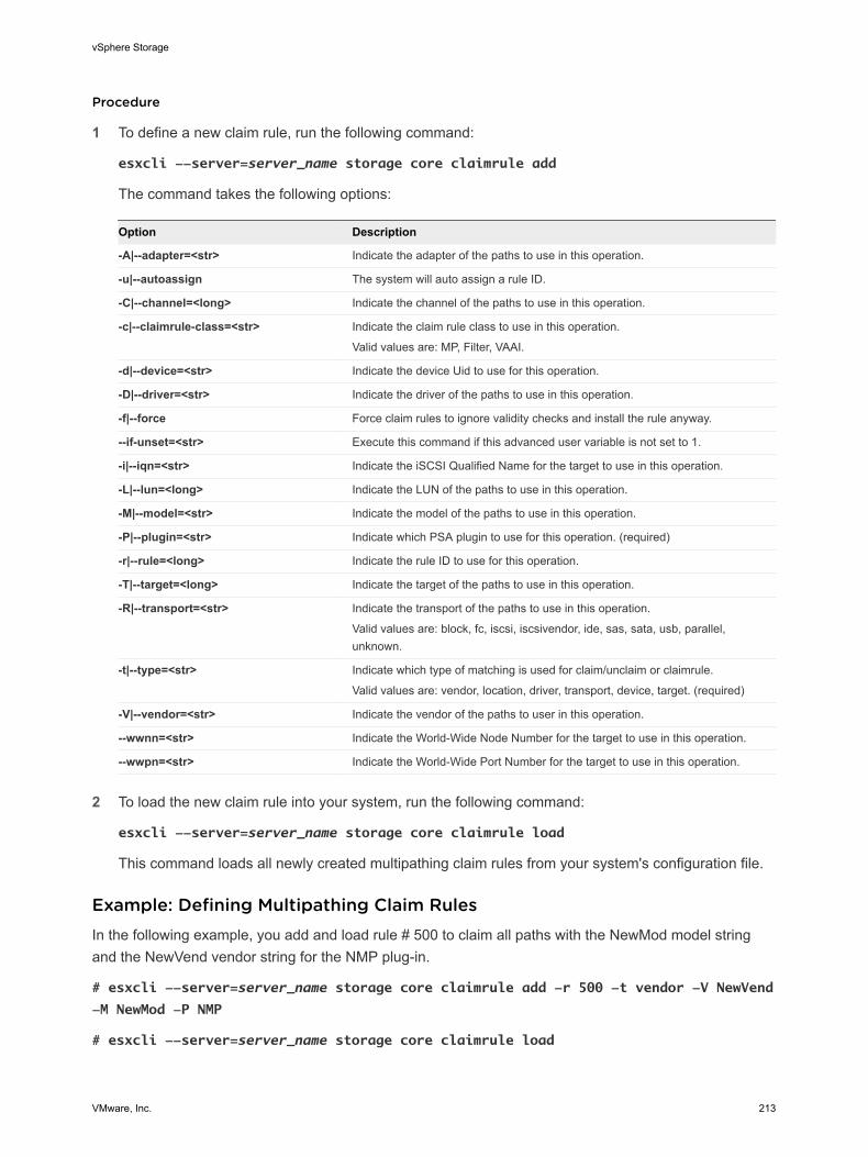
Procedure
1 To define a new claim rule, run the following command:
esxcli --server=server_name storage core claimrule add
The command takes the following options:
Option Description
-A|--adapter=<str> Indicate the adapter of the paths to use in this operation.
-u|--autoassign The system will auto assign a rule ID.
-C|--channel=<long> Indicate the channel of the paths to use in this operation.
-c|--claimrule-class=<str> Indicate the claim rule class to use in this operation.
Valid values are: MP, Filter, VAAI.
-d|--device=<str> Indicate the device Uid to use for this operation.
-D|--driver=<str> Indicate the driver of the paths to use in this operation.
-f|--force Force claim rules to ignore validity checks and install the rule anyway.
--if-unset=<str> Execute this command if this advanced user variable is not set to 1.
-i|--iqn=<str> Indicate the iSCSI Qualified Name for the target to use in this operation.
-L|--lun=<long> Indicate the LUN of the paths to use in this operation.
-M|--model=<str> Indicate the model of the paths to use in this operation.
-P|--plugin=<str> Indicate which PSA plugin to use for this operation. (required)
-r|--rule=<long> Indicate the rule ID to use for this operation.
-T|--target=<long> Indicate the target of the paths to use in this operation.
-R|--transport=<str> Indicate the transport of the paths to use in this operation.
Valid values are: block, fc, iscsi, iscsivendor, ide, sas, sata, usb, parallel,unknown.
-t|--type=<str> Indicate which type of matching is used for claim/unclaim or claimrule.
Valid values are: vendor, location, driver, transport, device, target. (required)
-V|--vendor=<str> Indicate the vendor of the paths to user in this operation.
--wwnn=<str> Indicate the World-Wide Node Number for the target to use in this operation.
--wwpn=<str> Indicate the World-Wide Port Number for the target to use in this operation.
2 To load the new claim rule into your system, run the following command:
esxcli --server=server_name storage core claimrule load
This command loads all newly created multipathing claim rules from your system's configuration file.
Example: Defining Multipathing Claim RulesIn the following example, you add and load rule # 500 to claim all paths with the NewMod model stringand the NewVend vendor string for the NMP plug-in.
# esxcli --server=server_name storage core claimrule add -r 500 -t vendor -V NewVend
-M NewMod -P NMP
# esxcli --server=server_name storage core claimrule load
vSphere Storage
VMware, Inc. 213
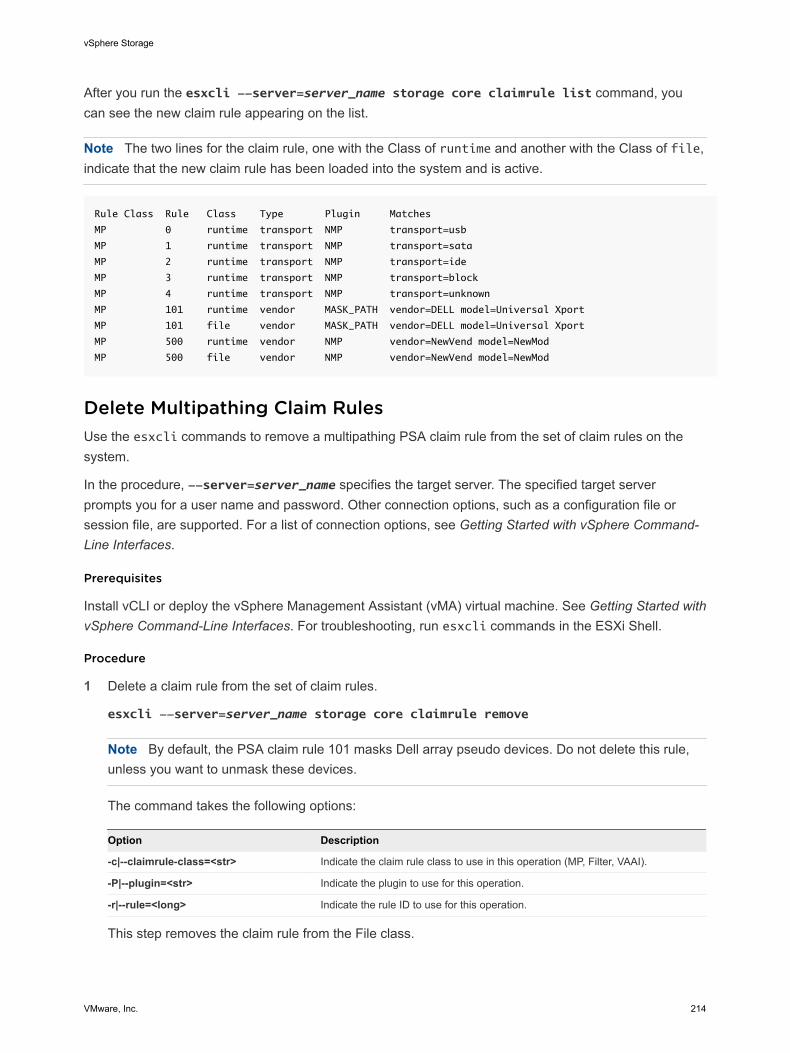
After you run the esxcli --server=server_name storage core claimrule list command, youcan see the new claim rule appearing on the list.
Note The two lines for the claim rule, one with the Class of runtime and another with the Class of file,indicate that the new claim rule has been loaded into the system and is active.
Rule Class Rule Class Type Plugin Matches
MP 0 runtime transport NMP transport=usb
MP 1 runtime transport NMP transport=sata
MP 2 runtime transport NMP transport=ide
MP 3 runtime transport NMP transport=block
MP 4 runtime transport NMP transport=unknown
MP 101 runtime vendor MASK_PATH vendor=DELL model=Universal Xport
MP 101 file vendor MASK_PATH vendor=DELL model=Universal Xport
MP 500 runtime vendor NMP vendor=NewVend model=NewMod
MP 500 file vendor NMP vendor=NewVend model=NewMod
Delete Multipathing Claim RulesUse the esxcli commands to remove a multipathing PSA claim rule from the set of claim rules on thesystem.
In the procedure, --server=server_name specifies the target server. The specified target serverprompts you for a user name and password. Other connection options, such as a configuration file orsession file, are supported. For a list of connection options, see Getting Started with vSphere Command-Line Interfaces.
Prerequisites
Install vCLI or deploy the vSphere Management Assistant (vMA) virtual machine. See Getting Started withvSphere Command-Line Interfaces. For troubleshooting, run esxcli commands in the ESXi Shell.
Procedure
1 Delete a claim rule from the set of claim rules.
esxcli --server=server_name storage core claimrule remove
Note By default, the PSA claim rule 101 masks Dell array pseudo devices. Do not delete this rule,unless you want to unmask these devices.
The command takes the following options:
Option Description
-c|--claimrule-class=<str> Indicate the claim rule class to use in this operation (MP, Filter, VAAI).
-P|--plugin=<str> Indicate the plugin to use for this operation.
-r|--rule=<long> Indicate the rule ID to use for this operation. This step removes the claim rule from the File class.
vSphere Storage
VMware, Inc. 214
2 Remove the claim rule from the system.
esxcli --server=server_name storage core claimrule load
This step removes the claim rule from the Runtime class.
Mask PathsYou can prevent the host from accessing storage devices or LUNs or from using individual paths to aLUN. Use the esxcli commands to mask the paths. When you mask paths, you create claim rules thatassign the MASK_PATH plug-in to the specified paths.
In the procedure, --server=server_name specifies the target server. The specified target serverprompts you for a user name and password. Other connection options, such as a configuration file orsession file, are supported. For a list of connection options, see Getting Started with vSphere Command-Line Interfaces.
Prerequisites
Install vCLI or deploy the vSphere Management Assistant (vMA) virtual machine. See Getting Started withvSphere Command-Line Interfaces. For troubleshooting, run esxcli commands in the ESXi Shell.
Procedure
1 Check what the next available rule ID is.
esxcli --server=server_name storage core claimrule list
The claim rules that you use to mask paths should have rule IDs in the range of 101 – 200. If thiscommand shows that rule 101 and 102 already exist, you can specify 103 for the rule to add.
2 Assign the MASK_PATH plug-in to a path by creating a new claim rule for the plug-in.
esxcli --server=server_name storage core claimrule add -P MASK_PATH
3 Load the MASK_PATH claim rule into your system.
esxcli --server=server_name storage core claimrule load
4 Verify that the MASK_PATH claim rule was added correctly.
esxcli --server=server_name storage core claimrule list
5 If a claim rule for the masked path exists, remove the rule.
esxcli --server=server_name storage core claiming unclaim
6 Run the path claiming rules.
esxcli --server=server_name storage core claimrule run
After you assign the MASK_PATH plug-in to a path, the path state becomes irrelevant and is no longermaintained by the host. As a result, commands that display the masked path's information might show thepath state as dead.
vSphere Storage
VMware, Inc. 215
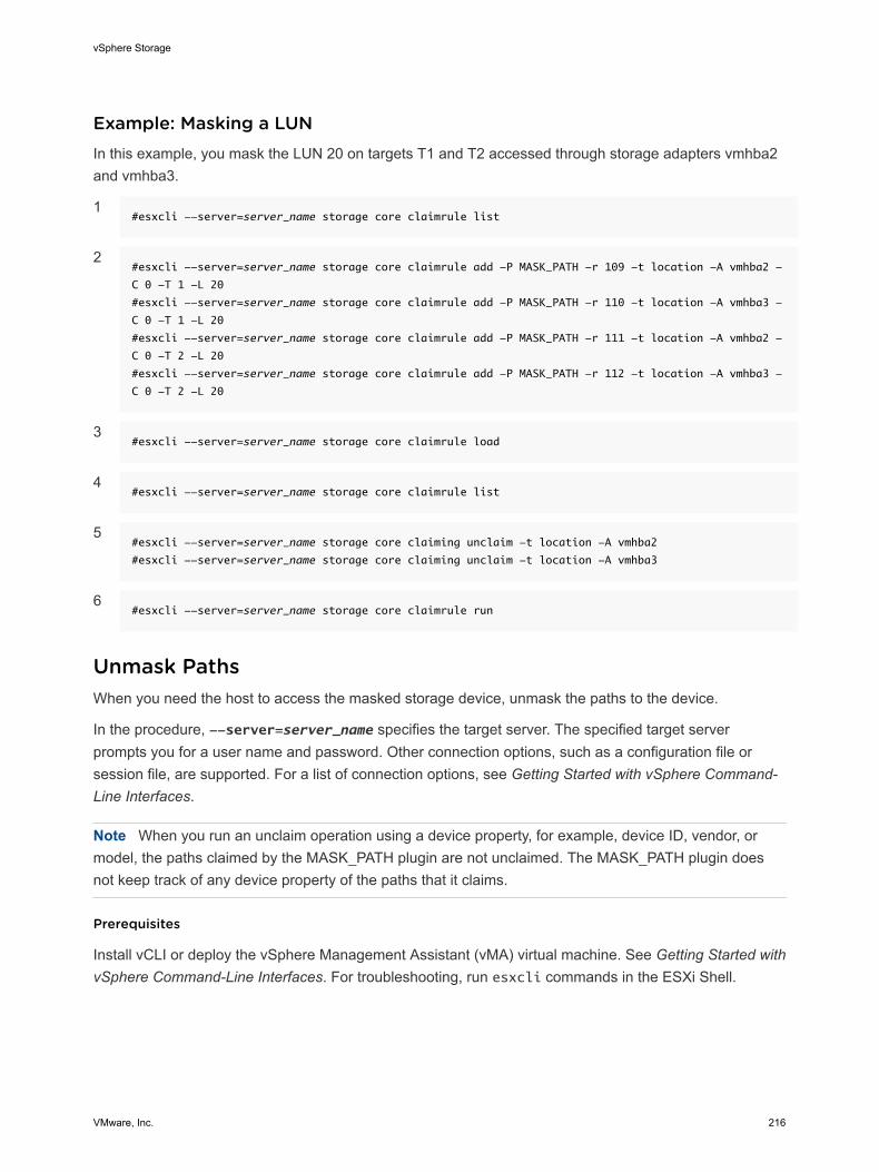
Example: Masking a LUNIn this example, you mask the LUN 20 on targets T1 and T2 accessed through storage adapters vmhba2and vmhba3.
1#esxcli --server=server_name storage core claimrule list
2#esxcli --server=server_name storage core claimrule add -P MASK_PATH -r 109 -t location -A vmhba2 -
C 0 -T 1 -L 20
#esxcli --server=server_name storage core claimrule add -P MASK_PATH -r 110 -t location -A vmhba3 -
C 0 -T 1 -L 20
#esxcli --server=server_name storage core claimrule add -P MASK_PATH -r 111 -t location -A vmhba2 -
C 0 -T 2 -L 20
#esxcli --server=server_name storage core claimrule add -P MASK_PATH -r 112 -t location -A vmhba3 -
C 0 -T 2 -L 20
3#esxcli --server=server_name storage core claimrule load
4#esxcli --server=server_name storage core claimrule list
5#esxcli --server=server_name storage core claiming unclaim -t location -A vmhba2
#esxcli --server=server_name storage core claiming unclaim -t location -A vmhba3
6#esxcli --server=server_name storage core claimrule run
Unmask PathsWhen you need the host to access the masked storage device, unmask the paths to the device.
In the procedure, --server=server_name specifies the target server. The specified target serverprompts you for a user name and password. Other connection options, such as a configuration file orsession file, are supported. For a list of connection options, see Getting Started with vSphere Command-Line Interfaces.
Note When you run an unclaim operation using a device property, for example, device ID, vendor, ormodel, the paths claimed by the MASK_PATH plugin are not unclaimed. The MASK_PATH plugin doesnot keep track of any device property of the paths that it claims.
Prerequisites
Install vCLI or deploy the vSphere Management Assistant (vMA) virtual machine. See Getting Started withvSphere Command-Line Interfaces. For troubleshooting, run esxcli commands in the ESXi Shell.
vSphere Storage
VMware, Inc. 216
Procedure
1 Delete the MASK_PATH claim rule.
esxcli --server=server_name storage core claimrule remove -r rule#
2 Verify that the claim rule was deleted correctly.
esxcli --server=server_name storage core claimrule list
3 Reload the path claiming rules from the configuration file into the VMkernel.
esxcli --server=server_name storage core claimrule load
4 Run the esxcli --server=server_name storage core claiming unclaim command for eachpath to the masked storage device.
For example:
esxcli --server=server_name storage core claiming unclaim -t location -A vmhba0 -
C 0 -T 0 -L 149
5 Run the path claiming rules.
esxcli --server=server_name storage core claimrule run
Your host can now access the previously masked storage device.
Define NMP SATP RulesThe NMP SATP claim rules specify which SATP should manage a particular storage device. Usually youdo not need to modify the NMP SATP rules. If you need to do so, use the esxcli commands to add arule to the list of claim rules for the specified SATP.
You might need to create a SATP rule when you install a third-party SATP for a specific storage array.
In the procedure, --server=server_name specifies the target server. The specified target serverprompts you for a user name and password. Other connection options, such as a configuration file orsession file, are supported. For a list of connection options, see Getting Started with vSphere Command-Line Interfaces.
Prerequisites
Install vCLI or deploy the vSphere Management Assistant (vMA) virtual machine. See Getting Started withvSphere Command-Line Interfaces. For troubleshooting, run esxcli commands in the ESXi Shell.
vSphere Storage
VMware, Inc. 217
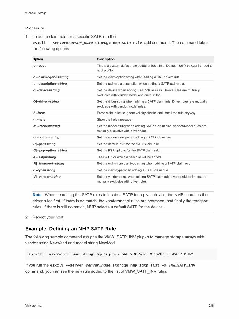
Procedure
1 To add a claim rule for a specific SATP, run theesxcli --server=server_name storage nmp satp rule add command. The command takesthe following options.
Option Description
-b|--boot This is a system default rule added at boot time. Do not modify esx.conf or add tohost profile.
-c|--claim-option=string Set the claim option string when adding a SATP claim rule.
-e|--description=string Set the claim rule description when adding a SATP claim rule.
-d|--device=string Set the device when adding SATP claim rules. Device rules are mutuallyexclusive with vendor/model and driver rules.
-D|--driver=string Set the driver string when adding a SATP claim rule. Driver rules are mutuallyexclusive with vendor/model rules.
-f|--force Force claim rules to ignore validity checks and install the rule anyway.
-h|--help Show the help message.
-M|--model=string Set the model string when adding SATP a claim rule. Vendor/Model rules aremutually exclusive with driver rules.
-o|--option=string Set the option string when adding a SATP claim rule.
-P|--psp=string Set the default PSP for the SATP claim rule.
-O|--psp-option=string Set the PSP options for the SATP claim rule.
-s|--satp=string The SATP for which a new rule will be added.
-R|--transport=string Set the claim transport type string when adding a SATP claim rule.
-t|--type=string Set the claim type when adding a SATP claim rule.
-V|--vendor=string Set the vendor string when adding SATP claim rules. Vendor/Model rules aremutually exclusive with driver rules.
Note When searching the SATP rules to locate a SATP for a given device, the NMP searches thedriver rules first. If there is no match, the vendor/model rules are searched, and finally the transportrules. If there is still no match, NMP selects a default SATP for the device.
2 Reboot your host.
Example: Defining an NMP SATP RuleThe following sample command assigns the VMW_SATP_INV plug-in to manage storage arrays withvendor string NewVend and model string NewMod.
# esxcli --server=server_name storage nmp satp rule add -V NewVend -M NewMod -s VMW_SATP_INV
If you run the esxcli --server=server_name storage nmp satp list -s VMW_SATP_INVcommand, you can see the new rule added to the list of VMW_SATP_INV rules.
vSphere Storage
VMware, Inc. 218
Scheduling Queues for Virtual Machine I/OsBy default, vSphere provides a mechanism that creates scheduling queues for every virtual machine file.Each file, for example .vmdk, gets its own bandwidth controls.
This mechanism ensures that I/O for a particular virtual machine file, such as .vmdk, goes into its ownseparate queue and does not interfere with I/Os from other files.
This capability is enabled by default. If you need to turn it off, you can do this by adjusting theVMkernel.Boot.isPerFileSchedModelActive parameter in the advanced system settings.
Edit Per File I/O SchedulingThe advanced VMkernel.Boot.isPerFileSchedModelActive parameter controls the per file I/Oscheduling mechanism. The mechanism is enabled by default.
Procedure
1 Browse to the host in the vSphere Web Client navigator.
2 Click the Manage tab, and click Settings.
3 Under System, click Advanced System Settings.
4 Under Advanced System Settings, select the VMkernel.Boot.isPerFileSchedModelActiveparameter and click the Edit icon.
5 Select one of the following options:
n To disable the per file scheduling mechanism, change the value to No.
Note After you turn off the per file I/O scheduling model, your host reverts to a legacyscheduling mechanism that uses a single I/O queue. The host maintains the single I/O queue foreach virtual machine and storage device pair. All I/Os between the virtual machine and its virtualdisks stored on the storage device are moved into this queue. As a result, I/Os from differentvirtual disks might interfere with each other in sharing the bandwidth and affect each othersperformance.
n To reenable the per file scheduling mechanism, change the value to Yes.
6 Reboot the host for the changes to take effect.
Use esxcli Commands to Enable or Disable Per File I/O SchedulingYou can use the esxcli commands to change to I/O scheduling capability. The capability is enabled bydefault.
In the procedure, --server=server_name specifies the target server. The specified target serverprompts you for a user name and password. Other connection options, such as a configuration file orsession file, are supported. For a list of connection options, see Getting Started with vSphere Command-Line Interfaces.
vSphere Storage
VMware, Inc. 219
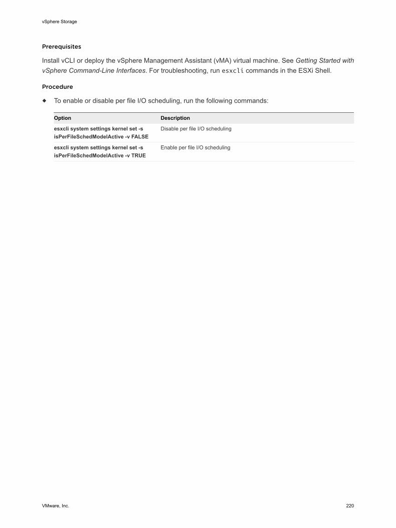
Prerequisites
Install vCLI or deploy the vSphere Management Assistant (vMA) virtual machine. See Getting Started withvSphere Command-Line Interfaces. For troubleshooting, run esxcli commands in the ESXi Shell.
Procedure
u To enable or disable per file I/O scheduling, run the following commands:
Option Description
esxcli system settings kernel set -sisPerFileSchedModelActive -v FALSE
Disable per file I/O scheduling
esxcli system settings kernel set -sisPerFileSchedModelActive -v TRUE
Enable per file I/O scheduling
vSphere Storage
VMware, Inc. 220

Raw Device Mapping 18Raw device mapping (RDM) provides a mechanism for a virtual machine to have direct access to a LUNon the physical storage subsystem.
The following topics contain information about RDMs and provide instructions on how to create andmanage RDMs.
This chapter includes the following topics:
n About Raw Device Mapping
n Raw Device Mapping Characteristics
n Create Virtual Machines with RDMs
n Manage Paths for a Mapped LUN
About Raw Device MappingAn RDM is a mapping file in a separate VMFS volume that acts as a proxy for a raw physical storagedevice. The RDM allows a virtual machine to directly access and use the storage device. The RDMcontains metadata for managing and redirecting disk access to the physical device.
The file gives you some of the advantages of direct access to a physical device while keeping someadvantages of a virtual disk in VMFS. As a result, it merges VMFS manageability with raw device access.
RDMs can be described in terms such as mapping a raw device into a datastore, mapping a system LUN,or mapping a disk file to a physical disk volume. All these terms refer to RDMs.
Figure 18‑1. Raw Device Mapping
VMFS volume
Virtualmachine
addressresolution
opens reads, writes
mapped devicemapping file
VMware, Inc. 221

Although VMware recommends that you use VMFS datastores for most virtual disk storage, on certainoccasions, you might need to use raw LUNs or logical disks located in a SAN.
For example, you need to use raw LUNs with RDMs in the following situations:
n When SAN snapshot or other layered applications run in the virtual machine. The RDM betterenables scalable backup offloading systems by using features inherent to the SAN.
n In any MSCS clustering scenario that spans physical hosts — virtual-to-virtual clusters as well asphysical-to-virtual clusters. In this case, cluster data and quorum disks should be configured as RDMsrather than as virtual disks on a shared VMFS.
Think of an RDM as a symbolic link from a VMFS volume to a raw LUN. The mapping makes LUNsappear as files in a VMFS volume. The RDM, not the raw LUN, is referenced in the virtual machineconfiguration. The RDM contains a reference to the raw LUN.
Using RDMs, you can:
n Use vMotion to migrate virtual machines using raw LUNs.
n Add raw LUNs to virtual machines using the vSphere Web Client.
n Use file system features such as distributed file locking, permissions, and naming.
Two compatibility modes are available for RDMs:
n Virtual compatibility mode allows an RDM to act exactly like a virtual disk file, including the use ofsnapshots.
n Physical compatibility mode allows direct access of the SCSI device for those applications that needlower level control.
Benefits of Raw Device MappingAn RDM provides a number of benefits, but it should not be used in every situation. In general, virtual diskfiles are preferable to RDMs for manageability. However, when you need raw devices, you must use theRDM.
RDM offers several benefits.
User-FriendlyPersistent Names
Provides a user-friendly name for a mapped device. When you use anRDM, you do not need to refer to the device by its device name. You referto it by the name of the mapping file, for example:
/vmfs/volumes/myVolume/myVMDirectory/myRawDisk.vmdk
Dynamic NameResolution
Stores unique identification information for each mapped device. VMFSassociates each RDM with its current SCSI device, regardless of changesin the physical configuration of the server because of adapter hardwarechanges, path changes, device relocation, and so on.
vSphere Storage
VMware, Inc. 222
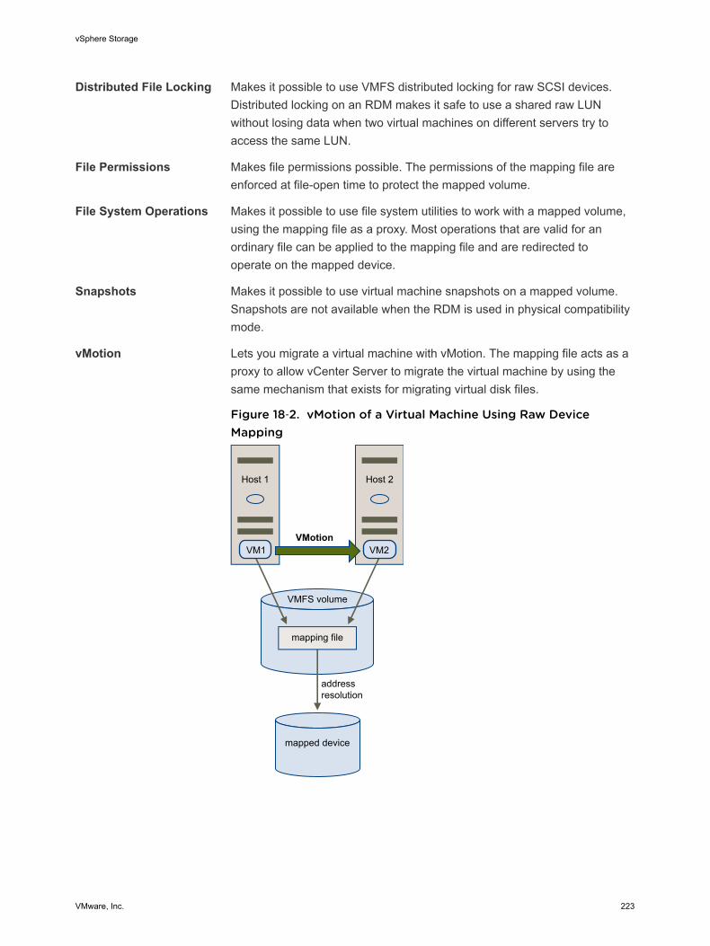
Distributed File Locking Makes it possible to use VMFS distributed locking for raw SCSI devices.Distributed locking on an RDM makes it safe to use a shared raw LUNwithout losing data when two virtual machines on different servers try toaccess the same LUN.
File Permissions Makes file permissions possible. The permissions of the mapping file areenforced at file-open time to protect the mapped volume.
File System Operations Makes it possible to use file system utilities to work with a mapped volume,using the mapping file as a proxy. Most operations that are valid for anordinary file can be applied to the mapping file and are redirected tooperate on the mapped device.
Snapshots Makes it possible to use virtual machine snapshots on a mapped volume.Snapshots are not available when the RDM is used in physical compatibilitymode.
vMotion Lets you migrate a virtual machine with vMotion. The mapping file acts as aproxy to allow vCenter Server to migrate the virtual machine by using thesame mechanism that exists for migrating virtual disk files.
Figure 18‑2. vMotion of a Virtual Machine Using Raw DeviceMapping
VMFS volume
mapping file
addressresolution
mapped device
Host 2Host 1
VM2VM1VMotion
vSphere Storage
VMware, Inc. 223
SAN ManagementAgents
Makes it possible to run some SAN management agents inside a virtualmachine. Similarly, any software that needs to access a device by usinghardware-specific SCSI commands can be run in a virtual machine. Thiskind of software is called SCSI target-based software. When you use SANmanagement agents, select a physical compatibility mode for the RDM.
N-Port ID Virtualization(NPIV)
Makes it possible to use the NPIV technology that allows a single FibreChannel HBA port to register with the Fibre Channel fabric using severalworldwide port names (WWPNs). This ability makes the HBA port appearas multiple virtual ports, each having its own ID and virtual port name.Virtual machines can then claim each of these virtual ports and use themfor all RDM traffic.
Note You can use NPIV only for virtual machines with RDM disks.
VMware works with vendors of storage management software to ensure that their software functionscorrectly in environments that include ESXi. Some applications of this kind are:
n SAN management software
n Storage resource management (SRM) software
n Snapshot software
n Replication software
Such software uses a physical compatibility mode for RDMs so that the software can access SCSIdevices directly.
Various management products are best run centrally (not on the ESXi machine), while others run well onthe virtual machines. VMware does not certify these applications or provide a compatibility matrix. To findout whether a SAN management application is supported in an ESXi environment, contact the SANmanagement software provider.
RDM Considerations and LimitationsCertain considerations and limitations exist when you use RDMs.
n The RDM is not available for direct-attached block devices or certain RAID devices. The RDM uses aSCSI serial number to identify the mapped device. Because block devices and some direct-attachRAID devices do not export serial numbers, they cannot be used with RDMs.
n If you are using the RDM in physical compatibility mode, you cannot use a snapshot with the disk.Physical compatibility mode allows the virtual machine to manage its own, storage-based, snapshotor mirroring operations.
Virtual machine snapshots are available for RDMs with virtual compatibility mode.
n You cannot map to a disk partition. RDMs require the mapped device to be a whole LUN.
vSphere Storage
VMware, Inc. 224
n If you use vMotion to migrate virtual machines with RDMs, make sure to maintain consistent LUN IDsfor RDMs across all participating ESXi hosts.
n Flash Read Cache does not support RDMs in physical compatibility. Virtual compatibility RDMs aresupported with Flash Read Cache.
Raw Device Mapping CharacteristicsAn RDM is a special mapping file in a VMFS volume that manages metadata for its mapped device. Themapping file is presented to the management software as an ordinary disk file, available for the usual file-system operations. To the virtual machine, the storage virtualization layer presents the mapped device asa virtual SCSI device.
Key contents of the metadata in the mapping file include the location of the mapped device (nameresolution), the locking state of the mapped device, permissions, and so on.
RDM Virtual and Physical Compatibility ModesYou can use RDMs in virtual compatibility or physical compatibility modes. Virtual mode specifies fullvirtualization of the mapped device. Physical mode specifies minimal SCSI virtualization of the mappeddevice, allowing the greatest flexibility for SAN management software.
In virtual mode, the VMkernel sends only READ and WRITE to the mapped device. The mapped deviceappears to the guest operating system exactly the same as a virtual disk file in a VMFS volume. The realhardware characteristics are hidden. If you are using a raw disk in virtual mode, you can realize thebenefits of VMFS such as advanced file locking for data protection and snapshots for streamliningdevelopment processes. Virtual mode is also more portable across storage hardware than physical mode,presenting the same behavior as a virtual disk file.
In physical mode, the VMkernel passes all SCSI commands to the device, with one exception: theREPORT LUNs command is virtualized so that the VMkernel can isolate the LUN to the owning virtualmachine. Otherwise, all physical characteristics of the underlying hardware are exposed. Physical modeis useful to run SAN management agents or other SCSI target-based software in the virtual machine.Physical mode also allows virtual-to-physical clustering for cost-effective high availability.
VMFS5 supports greater than 2TB disk size for RDMs in virtual and physical modes. You cannot relocatelarger than 2TB RDMs to datastores other than VMFS5.
Dynamic Name ResolutionThe RDM file supports dynamic name resolution when a path to a raw device changes.
VMFS uniquely identifies all mapped storage devices, and the identification is stored in its internal datastructures. Any change in the path to a raw device, such as a Fibre Channel switch failure or the additionof a new HBA, can change the device name. Dynamic name resolution resolves these changes andautomatically associates the original device with its new name.
vSphere Storage
VMware, Inc. 225
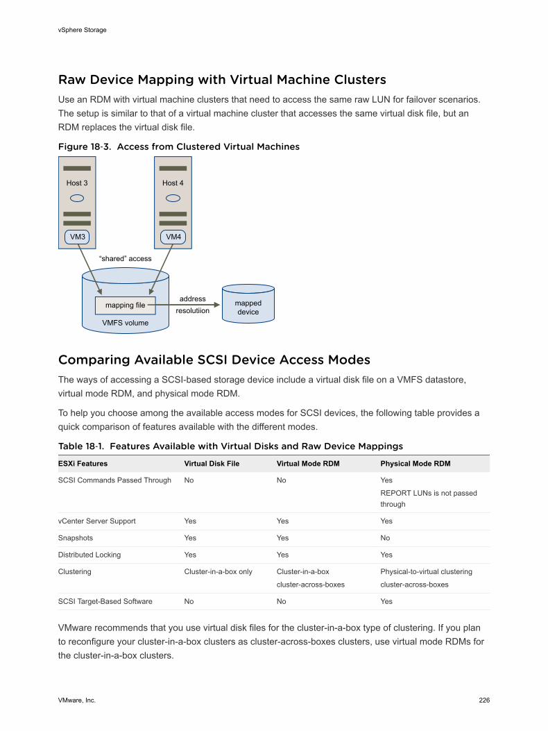
Raw Device Mapping with Virtual Machine ClustersUse an RDM with virtual machine clusters that need to access the same raw LUN for failover scenarios.The setup is similar to that of a virtual machine cluster that accesses the same virtual disk file, but anRDM replaces the virtual disk file.
Figure 18‑3. Access from Clustered Virtual Machines
addressresolutiion
Host 4Host 3
VMFS volume
“shared” access
VM4VM3
mappeddevice
mapping file
Comparing Available SCSI Device Access ModesThe ways of accessing a SCSI-based storage device include a virtual disk file on a VMFS datastore,virtual mode RDM, and physical mode RDM.
To help you choose among the available access modes for SCSI devices, the following table provides aquick comparison of features available with the different modes.
Table 18‑1. Features Available with Virtual Disks and Raw Device Mappings
ESXi Features Virtual Disk File Virtual Mode RDM Physical Mode RDM
SCSI Commands Passed Through No No Yes
REPORT LUNs is not passedthrough
vCenter Server Support Yes Yes Yes
Snapshots Yes Yes No
Distributed Locking Yes Yes Yes
Clustering Cluster-in-a-box only Cluster-in-a-box
cluster-across-boxes
Physical-to-virtual clustering
cluster-across-boxes
SCSI Target-Based Software No No Yes
VMware recommends that you use virtual disk files for the cluster-in-a-box type of clustering. If you planto reconfigure your cluster-in-a-box clusters as cluster-across-boxes clusters, use virtual mode RDMs forthe cluster-in-a-box clusters.
vSphere Storage
VMware, Inc. 226
Create Virtual Machines with RDMsWhen you give your virtual machine direct access to a raw SAN LUN, you create an RDM disk thatresides on a VMFS datastore and points to the LUN. You can create the RDM as an initial disk for a newvirtual machine or add it to an existing virtual machine. When creating the RDM, you specify the LUN tobe mapped and the datastore on which to put the RDM.
Although the RDM disk file has the same.vmdk extension as a regular virtual disk file, the RDM containsonly mapping information. The actual virtual disk data is stored directly on the LUN.
This procedure assumes that you are creating a new virtual machine. For information, see the vSphereVirtual Machine Administration documentation.
Procedure
1 Right-click any inventory object that is a valid parent object of a virtual machine, such as a datacenter, folder, cluster, resource pool, or host, and select New Virtual Machine.
2 Select Create a new virtual machine and click Next.
3 Follow the steps required to create a virtual machine.
4 On the Customize Hardware page, click the Virtual Hardware tab.
5 (Optional) To delete the default virtual hard disk that the system created for your virtual machine,move your cursor over the disk and click the Remove icon.
6 From the New drop-down menu at the bottom of the page, select RDM Disk and click Add.
7 From the list of SAN devices or LUNs, select a raw LUN for your virtual machine to access directlyand click OK.
The system creates an RDM disk that maps your virtual machine to the target LUN. The RDM disk isshown on the list of virtual devices as a new hard disk.
8 Click the New Hard Disk triangle to expand the properties for the RDM disk.
9 Select a location for the RDM disk.
You can place the RDM on the same datastore where your virtual machine configuration files reside,or select a different datastore.
Note To use vMotion for virtual machines with enabled NPIV, make sure that the RDM files and thevirtual machine files are located on the same datastore. You cannot perform Storage vMotion whenNPIV is enabled.
vSphere Storage
VMware, Inc. 227
10 Select a compatibility mode.
Option Description
Physical Allows the guest operating system to access the hardware directly. Physicalcompatibility is useful if you are using SAN-aware applications on the virtualmachine. However, a virtual machine with a physical compatibility RDM cannot becloned, made into a template, or migrated if the migration involves copying thedisk.
Virtual Allows the RDM to behave as if it were a virtual disk, so you can use suchfeatures as taking snapshots, cloning, and so on. When you clone the disk ormake a template out of it, the contents of the LUN are copied into a .vmdk virtualdisk file. When you migrate a virtual compatibility mode RDM, you can migrate themapping file or copy the contents of the LUN into a virtual disk.
11 If you selected virtual compatibility mode, select a disk mode.
Disk modes are not available for RDM disks using physical compatibility mode.
Option Description
Dependent Dependent disks are included in snapshots.
Independent - Persistent Disks in persistent mode behave like conventional disks on your physicalcomputer. All data written to a disk in persistent mode are written permanently tothe disk.
Independent - Nonpersistent Changes to disks in nonpersistent mode are discarded when you power off orreset the virtual machine. With nonpersistent mode, you can restart the virtualmachine with a virtual disk in the same state every time. Changes to the disk arewritten to and read from a redo log file that is deleted when you power off or reset.
12 Click OK.
Manage Paths for a Mapped LUNWhen you use virtual machines with RDMs, you can manage paths for mapped raw LUNs.
Procedure
1 In the vSphere Web Client, browse to the virtual machine.
2 Right-click the virtual machine and select Edit Settings.
3 Click the Virtual Hardware tab and click Hard Disk to expand the disk options menu.
4 Click Manage Paths.
5 Use the Edit Multipathing Policies dialog box to enable or disable paths, set multipathing policy, andspecify the preferred path.
For information on managing paths, see Chapter 17 Understanding Multipathing and Failover.
vSphere Storage
VMware, Inc. 228
Working with Virtual Volumes 19The Virtual Volumes functionality changes the storage management paradigm from managing spaceinside datastores to managing abstract storage objects handled by storage arrays. With Virtual Volumes,an individual virtual machine, not the datastore, becomes a unit of storage management, while storagehardware gains complete control over virtual disk content, layout, and management.
Historically, vSphere storage management used a datastore-centric approach. With this approach,storage administrators and vSphere administrators discuss in advance the underlying storagerequirements for virtual machines. The storage administrator then sets up LUNs or NFS shares andpresents them to ESXi hosts. The vSphere administrator creates datastores based on LUNs or NFS, anduses these datastores as virtual machine storage. Typically, the datastore is the lowest granularity level atwhich data management occurs from a storage perspective. However, a single datastore containsmultiple virtual machines, which might have different requirements. With the traditional approach,differentiation on a per virtual machine level is difficult.
The Virtual Volumes functionality helps to improve granularity and allows you to differentiate virtualmachine services on a per application level by offering a new approach to storage management. Ratherthan arranging storage around features of a storage system, Virtual Volumes arranges storage around theneeds of individual virtual machines, making storage virtual-machine centric.
Virtual Volumes maps virtual disks and their derivatives, clones, snapshots, and replicas, directly toobjects, called virtual volumes, on a storage system. This mapping allows vSphere to offload intensivestorage operations such as snapshot, cloning, and replication to the storage system.
By creating a volume for each virtual disk, you can set policies at the optimum level. You can decide inadvance what the storage requirements of an application are, and communicate these requirements tothe storage system, so that it creates an appropriate virtual disk based on these requirements. Forexample, if your virtual machine requires an active-active storage array, you no longer must select adatastore that supports the active-active model, but instead, you create an individual virtual volume thatwill be automatically placed to the active-active array.
This chapter includes the following topics:
n Virtual Volumes Concepts
n Guidelines when Using Virtual Volumes
n Virtual Volumes and Storage Protocols
n Virtual Volumes Architecture
VMware, Inc. 229
n Virtual Volumes and VMware Certificate Authority
n Before You Enable Virtual Volumes
n Configure Virtual Volumes
n Provision Virtual Machines on Virtual Datastores
Virtual Volumes ConceptsWith Virtual Volumes, abstract storage containers replace traditional storage volumes based on LUNs orNFS shares. In vCenter Server, the storage containers are represented by virtual datastores. Virtualdatastores remove artificial boundaries of traditional datastores and are used to store virtual volumes,objects that encapsulate virtual machine files.
Watch the video to learn more about different components of the Virtual Volumes functionality.
Virtual Volumes Part 1: Concepts(http://link.brightcove.com/services/player/bcpid2296383276001?bctid=ref:video_vvols_part1_concepts)
n Virtual Volumes
Virtual volumes are encapsulations of virtual machine files, virtual disks, and their derivatives.
n Virtual Volumes and Storage Providers
A Virtual Volumes storage provider, also called a VASA provider, is a software component that actsas a storage awareness service for vSphere. The provider mediates out-of-band communicationbetween vCenter Server and ESXi hosts on one side and a storage system on the other.
n Storage Containers
Unlike traditional LUN and NFS based vSphere storage, the Virtual Volumes functionality does notrequire preconfigured volumes on a storage side. Instead, Virtual Volumes uses a storage container,which is a pool of raw storage capacity or an aggregation of storage capabilities that a storagesystem can provide to virtual volumes.
n Protocol Endpoints
Although storage systems manage all aspects of virtual volumes, ESXi hosts have no direct accessto virtual volumes on the storage side. Instead, ESXi hosts use a logical I/O proxy, called theprotocol endpoint, to communicate with virtual volumes and virtual disk files that virtual volumesencapsulate. ESXi uses protocol endpoints to establish a data path on demand from virtualmachines to their respective virtual volumes.
n Virtual Datastores
A virtual datastore represents a storage container in vCenter Server and the vSphere Web Client.
n Virtual Volumes and VM Storage Policies
A virtual machine that runs on a virtual datastore requires a VM storage policy.
Virtual VolumesVirtual volumes are encapsulations of virtual machine files, virtual disks, and their derivatives.
vSphere Storage
VMware, Inc. 230
Virtual volumes are stored natively inside a storage system that is connected through Ethernet or SAN.They are exported as objects by a compliant storage system and are managed entirely by hardware onthe storage side. Typically, a unique GUID identifies a virtual volume. Virtual volumes are notpreprovisioned, but created automatically when you perform virtual machine management operations.These operations include a VM creation, cloning, and snapshotting. ESXi and vCenter Server associateone or more virtual volumes to a virtual machine. The system creates the following types of virtualvolumes for the core elements that make up the virtual machine:
n A data virtual volume that corresponds directly to each virtual disk .vmdk file. As virtual disk files ontraditional datastores, virtual volumes are presented to virtual machines as SCSI disks.
n A configuration virtual volume, or a home directory, represents a small directory that containsmetadata files for a virtual machine. The files include a .vmx file, descriptor files for virtual disks, logfiles, and so forth. The configuration virtual volume is formatted with a file system. When ESXi usesSCSI protocol to connect to storage, configuration virtual volumes are formatted with VMFS. WithNFS protocol, configuration virtual volumes are presented as an NFS directory.
Additional virtual volumes can be created for other virtual machine components and virtual diskderivatives, such as clones, snapshots, and replicas. These virtual volumes include a swap virtual volumeto hold virtual machine swap files and a virtual memory volume to hold the contents of virtual machinememory for a snapshot.
By using different virtual volumes for different VM components, you can apply and manipulate storagepolicies at the finest granularity level. For example, a virtual volume that contains a virtual disk can have aricher set of data services and performance levels than the virtual volume for the VM boot disk. Similarly,a snapshot virtual volume can use a different storage tier compared to a current virtual volume.
Virtual Volumes and Storage ProvidersA Virtual Volumes storage provider, also called a VASA provider, is a software component that acts as astorage awareness service for vSphere. The provider mediates out-of-band communication betweenvCenter Server and ESXi hosts on one side and a storage system on the other.
The storage provider is implemented through VMware APIs for Storage Awareness (VASA) and is used tomanage all aspects of Virtual Volumes storage. The storage provider integrates with the StorageMonitoring Service (SMS), shipped with vSphere, to communicate with vCenter Server and ESXi hosts.
The storage provider delivers information from the underlying storage, or storage container in the case ofVirtual Volumes, so that storage container capabilities can appear in vCenter Server and thevSphere Web Client. Then, in turn, the storage provider communicates virtual machine storagerequirements, which you can define in the form of a storage policy, to the storage layer. This integrationprocess ensures that a virtual volume created in the storage layer meets the requirements outlined in thepolicy.
vSphere Storage
VMware, Inc. 231
Typically, vendors are responsible for supplying storage providers that can integrate with vSphere andprovide support to Virtual Volumes. Every storage provider must be certified by VMware and properlydeployed. For information about deploying the Virtual Volumes storage provider, contact your storagevendor.
After you deploy the storage provider, you must register it in vCenter Server, so that it can communicatewith vSphere through the SMS.
Storage ContainersUnlike traditional LUN and NFS based vSphere storage, the Virtual Volumes functionality does not requirepreconfigured volumes on a storage side. Instead, Virtual Volumes uses a storage container, which is apool of raw storage capacity or an aggregation of storage capabilities that a storage system can provideto virtual volumes.
A storage container is a part of the logical storage fabric and is a logical unit of the underlying hardware.The storage container logically groups virtual volumes based on management and administrative needs.For example, the storage container can contain all virtual volumes created for a tenant in a multitenantdeployment, or a department in an enterprise deployment. Each storage container serves as a virtualvolume store and virtual volumes are allocated out of the storage container capacity.
Typically, a storage administrator on the storage side defines storage containers. The number of storagecontainers, their capacity and size depend on a vendor-specific implementation, but at least one containerfor each storage system is required.
Note A single storage container cannot span different physical arrays.
After you register a storage provider associated with the storage system, vCenter Server discovers allconfigured storage containers along with their storage capability profiles, protocol endpoints, and otherattributes. A single storage container can export multiple capability profiles. As a result, virtual machineswith diverse needs and different storage policy settings can be a part of the same storage container.
Initially, all discovered storage containers are not connected to any specific host, and you cannot seethem in the vSphere Web Client. To mount a storage container, you must map it to a virtual datastore.
Protocol EndpointsAlthough storage systems manage all aspects of virtual volumes, ESXi hosts have no direct access tovirtual volumes on the storage side. Instead, ESXi hosts use a logical I/O proxy, called the protocolendpoint, to communicate with virtual volumes and virtual disk files that virtual volumes encapsulate.ESXi uses protocol endpoints to establish a data path on demand from virtual machines to theirrespective virtual volumes.
Each virtual volume is bound to a specific protocol endpoint. When a virtual machine on the host performsan I/O operation, the protocol endpoint directs the I/O to the appropriate virtual volume. Typically, astorage system requires a very small number of protocol endpoints. A single protocol endpoint canconnect to hundreds or thousands of virtual volumes.
vSphere Storage
VMware, Inc. 232
On the storage side, a storage administrator configures protocol endpoints, one or several per storagecontainer. Protocol endpoints are a part of the physical storage fabric and are exported, along withassociated storage containers, by the storage system through a storage provider. After you map astorage container to a virtual datastore, protocol endpoints are discovered by ESXi and become visible inthe vSphere Web Client. Protocol endpoints can also be discovered during a storage rescan.
In the vSphere Web Client, the list of available protocol endpoints looks similar to the host storagedevices list. Different storage transports can be used to expose protocol endpoints to ESXi. When theSCSI-based transport is used, the protocol endpoint represents a proxy LUN defined by a T10-basedLUN WWN. For the NFS protocol, the protocol endpoint is a mount point, such as IP address and a sharename. You can configure multipathing on a SCSI based protocol endpoint, but not on an NFS basedprotocol endpoint. However, no matter which protocol you use, a storage array can provide multipleprotocol endpoints for availability purposes.
Virtual DatastoresA virtual datastore represents a storage container in vCenter Server and the vSphere Web Client.
After vCenter Server discovers storage containers exported by storage systems, you must mount them tobe able to use them. You use the datastore creation wizard in the vSphere Web Client to map a storagecontainer to a virtual datastore. The virtual datastore that you create corresponds directly to the specificstorage container and becomes the container's representation in vCenter Server and thevSphere Web Client.
From a vSphere administrator prospective, the virtual datastore is similar to any other datastore and isused to hold virtual machines. Like other datastores, the virtual datastore can be browsed and lists virtualvolumes by virtual machine name. Like traditional datastores, the virtual datastore supports unmountingand mounting. However, such operations as upgrade and resize are not applicable to the virtualdatastore. The virtual datastore capacity is configurable by the storage administrator outside of vSphere.
You can use virtual datastores with traditional VMFS and NFS datastores and with Virtual SAN.
Note The size of a virtual volume must be a multiple of 1 MB, with a minimum size of 1 MB. As a result,all virtual disks that you provision on a virtual datastore or migrate from any datastore other than thevirtual datastore should be an even multiple of 1 MB in size. If the virtual disk you migrate to the virtualdatastore is not an even multiple of 1 MB, extend the disk manually to the nearest even multiple of 1 MB.
Virtual Volumes and VM Storage PoliciesA virtual machine that runs on a virtual datastore requires a VM storage policy.
A VM storage policy is a set of rules that contains placement and quality of service requirements for avirtual machine. The policy enforces appropriate placement of the virtual machine within Virtual Volumesstorage and guarantees that storage can satisfy virtual machine requirements.
You use the VM Storage Policies interface to create a Virtual Volumes storage policy. When you assignthe new policy to the virtual machine, the policy enforces that the Virtual Volumes storage meets therequirements.
vSphere Storage
VMware, Inc. 233
If you do not create the VM storage policy compatible with the virtual datastore, the system uses defaultNo Requirements policy. The No Requirements policy is a generic Virtual Volumes policy that contains norules or storage specifications. The policy allows Virtual Volumes storage arrays to determine the mostappropriate placement for the VM objects.
Guidelines when Using Virtual VolumesThe Virtual Volumes functionality offers several benefits and advantages. When you work with VirtualVolumes, you must follow specific guidelines.
Virtual Volumes has the following characteristics:
n Virtual Volumes supports offloading a number of operations to storage hardware. These operationsinclude snapshotting, cloning, and Storage DRS.
n With Virtual Volumes, you can use advanced storage services that include replication, encryption,deduplication, and compression on individual virtual disks.
n Virtual Volumes supports such vSphere features as vMotion, Storage vMotion, snapshots, linkedclones, Flash Read Cache, and DRS.
n With Virtual Volumes, storage vendors can use native snapshot facilities to improve performance ofvSphere snapshots.
n You can use Virtual Volumes with storage arrays that support vSphere APIs for Array Integration(VAAI).
n Virtual Volumes supports backup software that uses vSphere APIs for Data Protection (VADP).
Virtual Volumes Guidelines and LimitationsFollow these guidelines when you use Virtual Volumes.
n Because the Virtual Volumes environment requires vCenter Server, you cannot use Virtual Volumeswith a standalone host.
n Virtual Volumes does not support RDMs.
n A Virtual Volumes storage container cannot span across different physical arrays.
n Host profiles that contain virtual datastores are vCenter Server specific. After you extract this type ofhost profile, you can attach it only to hosts and clusters managed by the same vCenter Server as thereference host.
Virtual Volumes and Storage ProtocolsThe Virtual Volumes functionality supports Fibre Channel, FCoE, iSCSI, and NFS. Storage transportsexpose protocol endpoints to ESXi hosts.
When the SCSI-based protocol is used, the protocol endpoint represents a LUN defined by a T10-basedLUN WWN. For the NFS protocol, the protocol endpoint is a mount point, such as IP address or DNSname and a share name.
vSphere Storage
VMware, Inc. 234
No matter what storage protocol is used, a virtual volume, like a files on other traditional datastores, ispresented to a virtual machine as a SCSI disk. Virtual Volumes on disk arrays supports the same set ofSCSI commands as VMFS and uses ATS as a locking mechanism.
Virtual Volumes on NAS devices supports the same NFS Remote Procedure Calls (RPCs) that arerequired by ESXi hosts to connect to NFS mount points.
These considerations and guidelines apply when you use different storage protocols:
n With NFS, you can use version 3. Virtual Volumes does not support NFS 4.1.
n IPv6 format is not supported.
n For iSCSI, you must activate the software iSCSI adapter. Configure Dynamic Discovery and enter theIP address of the Virtual Volumes Storage Provider. See Configure the Software iSCSI Adapter.
n You can configure multipathing on a SCSI-based protocol endpoint, but not on an NFS-basedprotocol endpoint. No matter which protocol you use, a storage array can provide multiple protocolendpoints for availability purposes.
Virtual Volumes ArchitectureAn architectural diagram provides an overview of how all components of the Virtual Volumes functionalityinteract with each other.
vSphere Storage
VMware, Inc. 235
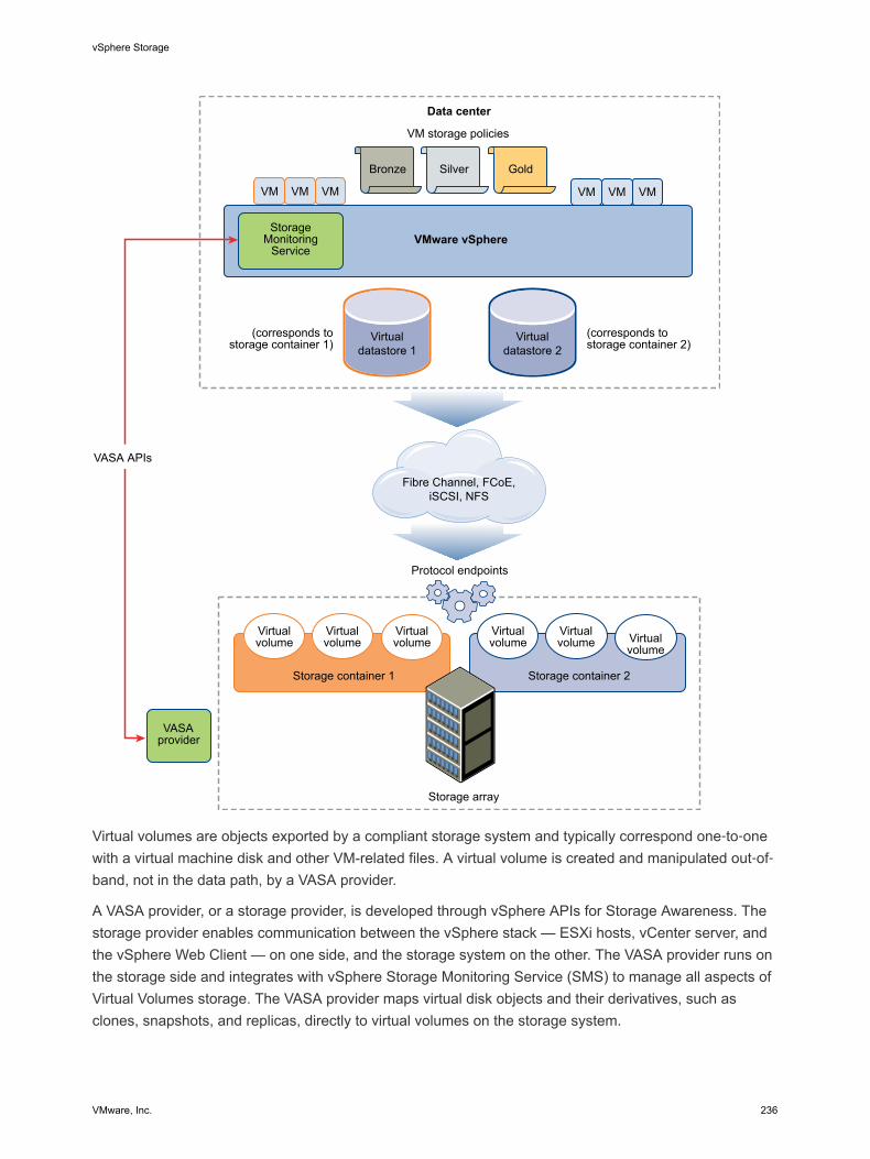
Data center
StorageMonitoring
Service
VM storage policies
VASA APIs
(corresponds tostorage container 1)
(corresponds tostorage container 2)
Virtualvolume
Virtualvolume
Storage container 1
Virtualvolume Virtual
volumeVirtualvolume
VASAprovider
Storage container 2
Storage array
VMware vSphere
VMVMVM VM VMVM
Silver Gold
Virtualvolume
Protocol endpoints
Virtualdatastore 1
Virtualdatastore 2
Fibre Channel, FCoE,iSCSI, NFS
Bronze
Virtual volumes are objects exported by a compliant storage system and typically correspond one‐to‐onewith a virtual machine disk and other VM-related files. A virtual volume is created and manipulated out‐of‐band, not in the data path, by a VASA provider.
A VASA provider, or a storage provider, is developed through vSphere APIs for Storage Awareness. Thestorage provider enables communication between the vSphere stack — ESXi hosts, vCenter server, andthe vSphere Web Client — on one side, and the storage system on the other. The VASA provider runs onthe storage side and integrates with vSphere Storage Monitoring Service (SMS) to manage all aspects ofVirtual Volumes storage. The VASA provider maps virtual disk objects and their derivatives, such asclones, snapshots, and replicas, directly to virtual volumes on the storage system.
vSphere Storage
VMware, Inc. 236
ESXi hosts have no direct access to the virtual volumes storage. Instead, the hosts access virtualvolumes through an intermediate point in the data path, called the protocol endpoint. Protocol endpointsestablish a data path on demand from virtual machines to their respective virtual volumes and serve as agateway for direct in-band I/O between ESXi hosts and the storage system. ESXi can use Fibre Channel,FCoE, iSCSI, and NFS protocols for in-band communication.
Virtual volumes reside inside storage containers that logically represent a pool of physical disks on thestorage system. In the vSphere stack, storage containers are presented as virtual datastores. A singlestorage container can export multiple storage capability sets. As a result, when you create a virtualmachine on the virtual datastore, you can use different storage policies to place virtual volumes inside thesame storage container in such a way that diverse storage needs of a virtual machine are met.
Watch the video for information about Virtual Volumes architecture.
Virtual Volumes Part 2: Architecture(http://link.brightcove.com/services/player/bcpid2296383276001?bctid=ref:video_vvols_part2_architecture)
Virtual Volumes and VMware Certificate AuthorityvSphere 6.0.x includes the VMware Certificate Authority (VMCA). By default, VMCA generates all internalcertificates used in vSphere environment, including certificates for newly added ESXi hosts and storageVASA providers that manage or represent Virtual Volumes storage systems.
Communication with the VASA provider is protected by SSL certificates. These certificates can come fromthe VASA provider or from VMCA.
n Certificates can be directly provided by the VASA provider for long-term use, and can be either self-generated and self-signed, or derived from an external Certificate Authority.
n Certificates can be generated by VMCA for use by the VASA provider.
When a host or VASA provider is registered, VMCA follows these steps automatically, withoutinvolvement from the vSphere administrator.
1 When a VASA provider is first added to vCenter Server storage management service (SMS), itproduces a self‐signed certificate.
2 After verifying the certificate, SMS requests a Certificate Signing Request (CSR) from the VASAprovider.
3 After receiving and validating the CSR, SMS presents it to VMCA on behalf of the VASA provider,requesting a CA signed certificate.
VMCA can be configured to function as a standalone CA, or as a subordinate to an enterprise CA. Ifyou set up VMCA as a subordinate CA, VMCA signs the CSR with the full chain.
4 The signed certificate along with the root certificate is passed to the VASA provider, so it canauthenticate all future secure connections originating from SMS on vCenter Server and on ESXihosts.
vSphere Storage
VMware, Inc. 237
Before You Enable Virtual VolumesTo work with Virtual Volumes, you must make sure that your storage and vSphere environment are set upcorrectly.
Follow these guidelines to prepare your storage system environment for Virtual Volumes. For additionalinformation, contact your storage vendor.
n The storage system or storage array that you use must be able to support Virtual Volumes andintegrate with vSphere through vSphere APIs for Storage Awareness (VASA).
n A Virtual Volumes storage provider must be deployed.
n Protocol endpoints, storage containers, and storage profiles must be configured on the storage side.
Prepare your vSphere environment.
n Make sure to follow appropriate setup guidelines for the type of storage you use, Fibre Channel,FCoE, iSCSI, or NFS. If required, install and configure storage adapters on your ESXi hosts.
If you use iSCSI, activate the software iSCSI adapters on your ESXi hosts. Configure DynamicDiscovery and enter the IP address of your Virtual Volumes storage system.
n Synchronize all components in the storage array with vCenter Server and all ESXi hosts. UseNetwork Time Protocol (NTP) to do this synchronization.
Synchronize vSphere Storage Environment with a Network TimeServerBefore you enable Virtual Volumes, make sure all machines on your vSphere network have their clockssynchronized.
Procedure
1 Select the host in the vSphere inventory.
2 Click the Manage tab and click Settings.
3 In the System section, select Time Configuration.
4 Click Edit and set up the NTP server.
a Select Use Network Time Protocol (Enable NTP client).
b Set the NTP Service Startup Policy.
c Enter the IP addresses of the NTP servers to synchronize with.
d Click Start or Restart in the NTP Service Status section.
5 Click OK.
The host synchronizes with the NTP server.
vSphere Storage
VMware, Inc. 238
Configure Virtual VolumesYou must complete a series of steps to configure your Virtual Volumes environment.
Prerequisites
Follow guidelines in Before You Enable Virtual Volumes.
Procedure
1 Register Storage Providers for Virtual Volumes
Your Virtual Volumes environment must include storage providers, also called VASA providers.Typically, third-party vendors develop storage providers through the VMware APIs for StorageAwareness (VASA). Storage providers facilitate communication between vSphere and the storageside. You must register the storage provider in vCenter Server to be able to work with VirtualVolumes.
2 Create a Virtual Datastore
You use the New Datastore wizard to create a virtual datastore.
3 Review and Manage Protocol Endpoints
ESXi hosts use a logical I/O proxy, called protocol endpoint, to communicate with virtual volumesand virtual disk files that virtual volumes encapsulate. Protocol endpoints are exported, along withassociated storage containers, by the storage system through a storage provider. Protocol endpointsbecome visible in the vSphere Web Client after you map a storage container to a virtual datastore.You can review properties of protocol endpoints and modify specific settings.
4 (Optional) Change the Path Selection Policy for a Protocol Endpoint
If your ESXi host uses SCSI-based transport to communicate with protocol endpoints representing astorage array, you can modify default multipathing policies assigned to protocol endpoints. Use theEdit Multipathing Policies dialog box to change a path selection policy.
What to do next
You can now provision virtual machines on the virtual datastore. For information on creating virtualmachines, see the vSphere Virtual Machine Administration documentation.
For troubleshooting information, see the vSphere Troubleshooting documentation.
Register Storage Providers for Virtual VolumesYour Virtual Volumes environment must include storage providers, also called VASA providers. Typically,third-party vendors develop storage providers through the VMware APIs for Storage Awareness (VASA).Storage providers facilitate communication between vSphere and the storage side. You must register thestorage provider in vCenter Server to be able to work with Virtual Volumes.
vSphere Storage
VMware, Inc. 239
After registration, the Virtual Volumes provider communicates with vCenter Server and reportscharacteristics of underlying storage. The characteristics appear in the VM Storage Policies interface andcan be used to create a VM storage policy compatible with the virtual datastore. After you apply thisstorage policy to a virtual machine, the policy is pushed to Virtual Volumes storage. The policy enforcesoptimal placement of the virtual machine within Virtual Volumes storage and guarantees that storage cansatisfy virtual machine requirements.
Prerequisites
Verify that the storage provider component is installed on the storage side and obtain its credentials fromyour storage administrator. For information, contact your vendor.
Procedure
1 Browse to vCenter Server in the vSphere Web Client navigator.
2 Click the Manage tab, and click Storage Providers.
3 Click the Register a new storage provider icon.
4 (Optional) To direct vCenter Server to the storage provider certificate, select the Use storageprovider certificate option and specify the certificate's location.
If you do not select this option, a thumbprint of the certificate is displayed. You can check thethumbprint and approve it.
5 Click OK to complete the registration.
vCenter Server discovers and registers the Virtual Volumes storage provider.
Create a Virtual DatastoreYou use the New Datastore wizard to create a virtual datastore.
Procedure
1 In the vSphere Web Client navigator, select vCenter Inventory Lists > Datastores
2 Click the Create a New Datastore icon.
3 Type the datastore name and if required, select the placement location for the datastore.
Make sure to use the name that does not duplicate another datastore name in your data centerenvironment.
If you mount the same virtual datastore to several hosts, the name of the datastore must beconsistent across all hosts.
4 Select VVOL as the datastore type.
5 From the list of storage containers, select a backing storage container.
6 Select the hosts that require access to the datastore.
7 Review the configuration options and click Finish.
vSphere Storage
VMware, Inc. 240
What to do next
After you create the virtual datastore, you can perform such datastore operations as renaming thedatastore, browsing datastore files, unmounting the datastore, and so on.
You cannot add the virtual datastore to a datastore cluster.
Review and Manage Protocol EndpointsESXi hosts use a logical I/O proxy, called protocol endpoint, to communicate with virtual volumes andvirtual disk files that virtual volumes encapsulate. Protocol endpoints are exported, along with associatedstorage containers, by the storage system through a storage provider. Protocol endpoints become visiblein the vSphere Web Client after you map a storage container to a virtual datastore. You can reviewproperties of protocol endpoints and modify specific settings.
Procedure
1 Browse to the host in the vSphere Web Client navigator.
2 Click the Manage tab, and click Storage.
3 Click Protocol Endpoints.
4 To view details for a specific item, select this item from the list.
5 Use tabs under Protocol Endpoint Details to access additional information and modify properties forthe selected protocol endpoint.
Tab Description
Properties View the item properties and characteristics. For SCSI (block) items, view andedit multipathing policies.
Paths (SCSI protocol endpoints only) Display paths available for the protocol endpoint. Disable or enable a selectedpath. Change the Path Selection Policy.
Datastores Display a corresponding virtual datastore. Perform datastore managementoperations.
(Optional) Change the Path Selection Policy for a ProtocolEndpointIf your ESXi host uses SCSI-based transport to communicate with protocol endpoints representing astorage array, you can modify default multipathing policies assigned to protocol endpoints. Use the EditMultipathing Policies dialog box to change a path selection policy.
Procedure
1 Browse to the host in the vSphere Web Client navigator.
2 Click the Manage tab, and click Storage.
3 Click Protocol Endpoints.
4 Select the protocol endpoint whose paths you want to change and click the Properties tab.
vSphere Storage
VMware, Inc. 241
5 Under Multipathing Policies, click Edit Multipathing.
6 Select a path policy.
n Fixed (VMware)
n Most Recently Used (VMware)
n Round Robin (VMware)
7 For the fixed policy, specify the preferred path.
8 Click OK to save your settings and exit the dialog box.
Provision Virtual Machines on Virtual DatastoresYou can provision virtual machines on a virtual datastore.
Note All virtual disks that you provision on a virtual datastore should be an even multiple of 1 MB.
A virtual machine that runs on a virtual datastore requires an appropriate VM storage policy.
After you provision the virtual machine, you can perform typical VM management tasks. For informationsee the vSphere Virtual Machine Administration documentation.
For troubleshooting information, see the vSphere Troubleshooting documentation.
Procedure
1 Define a VM Storage Policy for Virtual Volumes
You can create a VM storage policy compatible with a virtual datastore.
2 Assign the Virtual Volumes Storage Policy to Virtual Machines
To guarantee that the virtual datastore fulfills specific storage requirements when allocating a virtualmachine, associate the Virtual Volumes storage policy with the virtual machine.
3 Change Default Storage Policy for a Virtual Datastore
For virtual machines provisioned on virtual datastores, VMware provides a default No Requirementspolicy. You cannot edit this policy, but you can designate a newly created policy as default.
Define a VM Storage Policy for Virtual VolumesYou can create a VM storage policy compatible with a virtual datastore.
Prerequisites
Verify that the Virtual Volumes storage provider is available and active. See Register Storage Providersfor Virtual Volumes.
Procedure
1 From the vSphere Web Client Home, click Policies and Profiles > VM Storage Policies.
2 Click the Create a new VM storage policy icon.
vSphere Storage
VMware, Inc. 242

3 Select the vCenter Server instance.
4 Type a name and a description for the storage policy and click Next.
5 On the Rule Set page, select the Virtual Volumes storage provider from the Rules based on dataservices drop-down menu.
The page expands to show data services provided by the Virtual Volumes storage resource.
6 Select a data service to include and specify its value.
Make sure that the values you provide are within the range of values advertised by the VirtualVolumes profile.
Based on your input, the storage consumption mechanism calculates the amount of space requiredfor a virtual disk that will reside on the virtual datastore.
7 Complete the creation of the storage policy and click Finish.
The new VM storage policy compatible with Virtual Volumes appears on the list.
What to do next
You can now associate this policy with a virtual machine, or designate the policy as default.
Assign the Virtual Volumes Storage Policy to Virtual MachinesTo guarantee that the virtual datastore fulfills specific storage requirements when allocating a virtualmachine, associate the Virtual Volumes storage policy with the virtual machine.
You can assign the Virtual Volumes storage policy during an initial deployment of a virtual machine, orwhen performing other virtual machine operations, such as cloning or migrating. This topic describes howto assign the Virtual Volumes storage policy when you create a new virtual machine. For informationabout other VM provisioning methods, see the vSphere Virtual Machine Administration documentation.
You can apply the same storage policy to the virtual machine configuration file and all its virtual disks. Ifstorage requirements for your virtual disks and the configuration file are different, you can associatedifferent storage policies with the VM configuration file and the selected virtual disks.
Procedure
1 In the vSphere Web Client, start the virtual machine provisioning process and follow appropriatesteps.
2 Assign the same storage policy to all virtual machine files and disks.
a On the Select Storage page, select the storage policy compatible with Virtual Volumes, forexample VVols Silver, from the VM Storage Policy drop-down menu.
b Select the virtual datastore from the list of available datastores and click Next.
The datastore becomes the destination storage resource for the virtual machine configuration file andall virtual disks.
vSphere Storage
VMware, Inc. 243
3 Change the storage policy for the virtual disk.
Use this option if requirements for storage placement are different for virtual disks.
a On the Customize Hardware page, expand the New hard disk pane.
b From the VM storage policy drop-down menu, select the appropriate storage policy, for exampleVVols Gold, that you want to assign to the virtual disk.
4 Complete the virtual machine provisioning process.
After you create the virtual machine, the Summary tab displays the assigned storage policies and theircompliance status.
What to do next
If storage placement requirements for the configuration file or the virtual disks change, you can latermodify the virtual policy assignment. See Change Storage Policy Assignment for Virtual Machine Filesand Disks.
Change Default Storage Policy for a Virtual DatastoreFor virtual machines provisioned on virtual datastores, VMware provides a default No Requirementspolicy. You cannot edit this policy, but you can designate a newly created policy as default.
Prerequisites
Create a storage policy compatible with Virtual Volumes.
Procedure
1 Browse to the virtual datastore whose default storage policy you want to change.
2 Click the Manage tab, and click Settings.
3 Click General, and click Edit in the Default Storage Policy pane.
4 From the list of available storage policies, select a policy that you want to designate as default andclick OK.
The selected storage policy becomes the default policy for the virtual datastore. vSphere assigns thispolicy to any virtual machine objects that you provision on the virtual datastore when no other policy isexplicitly selected.
vSphere Storage
VMware, Inc. 244
Virtual Machine Storage Policies 20Virtual machine storage policies are essential to virtual machine provisioning. These policies help youdefine storage requirements for the virtual machine and control which type of storage is provided for thevirtual machine, how the virtual machine is placed within the storage, and which data services are offeredfor the virtual machine.
When you define a storage policy, you specify storage requirements for applications that run on virtualmachines. After you apply this storage policy to a virtual machine, the virtual machine is placed in aspecific datastore that can satisfy the storage requirements. In software-defined storage environments,such as Virtual SAN and Virtual Volumes, the storage policy also determines how the virtual machinestorage objects are provisioned and allocated within the storage resource to guarantee the required levelof service. In environments with third-party I/O filters installed, you can use storage policies to enable anadditional level of data services, such as caching and replication, for virtual disks.
This chapter includes the following topics:n Upgrading Legacy Storage Profiles
n Understanding Virtual Machine Storage Policies
n Working with Virtual Machine Storage Policies
n Creating and Managing VM Storage Policies
n Storage Policies and Virtual Machines
Upgrading Legacy Storage ProfilesIn vSphere 5.x, virtual machine storage policies were called storage profiles and had a different format.When you upgrade the vSphere environment from a 5.x version to vSphere 6.x, storage profiles that youcreated in the earlier versions are converted to storage policies.
All the components of legacy storage profiles are transformed into new formats or objects. Any system-defined storage capabilities are converted into storage-specific data services based on metadata. User-defined capabilities become datastore tags.
VMware, Inc. 245
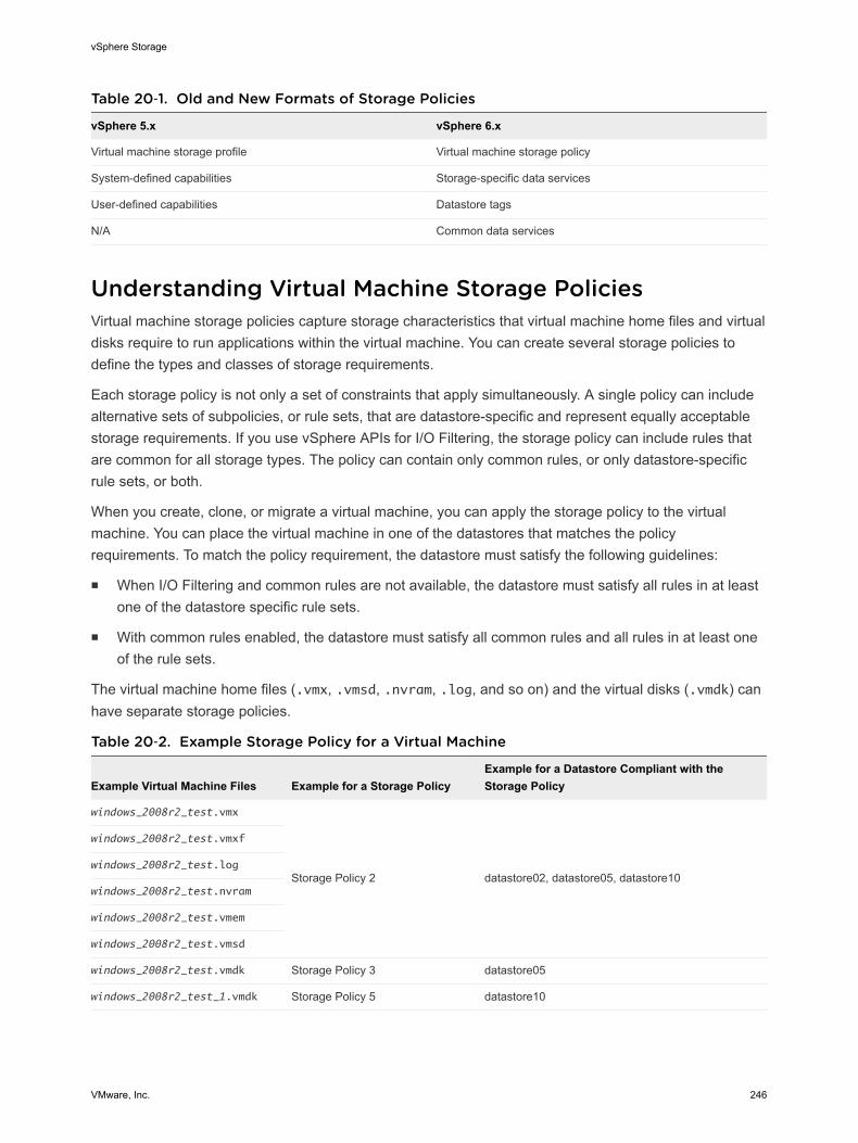
Table 20‑1. Old and New Formats of Storage Policies
vSphere 5.x vSphere 6.x
Virtual machine storage profile Virtual machine storage policy
System-defined capabilities Storage-specific data services
User-defined capabilities Datastore tags
N/A Common data services
Understanding Virtual Machine Storage PoliciesVirtual machine storage policies capture storage characteristics that virtual machine home files and virtualdisks require to run applications within the virtual machine. You can create several storage policies todefine the types and classes of storage requirements.
Each storage policy is not only a set of constraints that apply simultaneously. A single policy can includealternative sets of subpolicies, or rule sets, that are datastore-specific and represent equally acceptablestorage requirements. If you use vSphere APIs for I/O Filtering, the storage policy can include rules thatare common for all storage types. The policy can contain only common rules, or only datastore-specificrule sets, or both.
When you create, clone, or migrate a virtual machine, you can apply the storage policy to the virtualmachine. You can place the virtual machine in one of the datastores that matches the policyrequirements. To match the policy requirement, the datastore must satisfy the following guidelines:
n When I/O Filtering and common rules are not available, the datastore must satisfy all rules in at leastone of the datastore specific rule sets.
n With common rules enabled, the datastore must satisfy all common rules and all rules in at least oneof the rule sets.
The virtual machine home files (.vmx, .vmsd, .nvram, .log, and so on) and the virtual disks (.vmdk) canhave separate storage policies.
Table 20‑2. Example Storage Policy for a Virtual Machine
Example Virtual Machine Files Example for a Storage PolicyExample for a Datastore Compliant with theStorage Policy
windows_2008r2_test.vmx
Storage Policy 2 datastore02, datastore05, datastore10
windows_2008r2_test.vmxf
windows_2008r2_test.log
windows_2008r2_test.nvram
windows_2008r2_test.vmem
windows_2008r2_test.vmsd
windows_2008r2_test.vmdk Storage Policy 3 datastore05
windows_2008r2_test_1.vmdk Storage Policy 5 datastore10
vSphere Storage
VMware, Inc. 246
Storage Policies and RulesRules that you include in a storage policy can be based on storage-specific data services and tags, or therules can be common.
n Common Rules
Common rules are based on data services that are generic for all types of storage and do notdepend on a datastore. These additional services become available in the VM Storage Policiesinterface when you install third-party I/O filters developed through vSphere APIs for I/O Filtering. Youcan reference these data services in a VM storage policy.
n Rules Based on Storage-Specific Data Services
These rules are based on data services that storage entities such as Virtual SAN and VirtualVolumes advertise.
n Rules Based on Tags
Rules based on tags reference datastore tags that you associate with specific datastores. You canapply more than one tag to a datastore.
Common RulesCommon rules are based on data services that are generic for all types of storage and do not depend ona datastore. These additional services become available in the VM Storage Policies interface when youinstall third-party I/O filters developed through vSphere APIs for I/O Filtering. You can reference thesedata services in a VM storage policy.
Unlike storage-specific rules, common rules do not define storage placement and storage requirementsfor a virtual machine, but ensure that additional data services, such as I/O filters, become enabled for thevirtual machine. No matter which datastore the virtual machine runs on, the enabled filters can providethe following services:
n Caching. Configures a cache for virtual disk data. The filter can use a local cache or a flash storagedevice to cache the data and increase the Input/Output Operations Per Second and hardwareutilization rates for the virtual disk.
n Replication. Replicates virtual machine or virtual disks to external targets such as another host orcluster.
For more information about I/O filters, see Chapter 21 Filtering Virtual Machine I/O.
Rules Based on Storage-Specific Data ServicesThese rules are based on data services that storage entities such as Virtual SAN and Virtual Volumesadvertise.
To supply information about underlying storage to vCenter Server, Virtual SAN and Virtual Volumes usestorage providers, also called VASA providers. Storage information and datastore characteristics appearin the VM Storage Policies interface of the vSphere Web Client as data services offered by the specificdatastore type.
vSphere Storage
VMware, Inc. 247
A single datastore can offer multiple services. The data services are grouped in a datastore profile thatoutlines the quality of service that the datastore can deliver.
When you create rules for a VM storage policy, you reference data services that a specific datastoreadvertises. To the virtual machine that uses this policy, the datastore guarantees that it can satisfy thestorage requirements of the virtual machine. The datastore also can provide the virtual machine with aspecific set of characteristics for capacity, performance, availability, redundancy, and so on.
For more information about storage providers, see Chapter 25 Using Storage Providers.
Rules Based on TagsRules based on tags reference datastore tags that you associate with specific datastores. You can applymore than one tag to a datastore.
Typically, tags serve the following purposes:
n Attach a broad storage-level definition to datastores that are not represented by any storageproviders, for example, VMFS and NFS datastores.
n Encode policy-relevant information that is not advertised through vSphere API for Storage Awareness(VASA), such as geographical location or administrative group.
Similar to storage-specific services, all tags associated with datastores appear in the VM Storage Policiesinterface. You can use the tags when you define rules for the storage policies.
About Datastore-Specific and Common Rule SetsA storage policy can include one or several rule sets that describe requirements for virtual machinestorage resources. It can also include common rules.
If common rules are not available in your environment or not defined, you can create a policy thatincludes datastore-specific rule sets. To define a policy, one rule set is required. Additional rule sets areoptional. Multiple rule sets allow a single policy to define alternative selection parameters, often fromseveral storage providers.
A single rule set contains one or several rules. Each rule can be based on a single underlying dataservice that a storage entity guarantees. The rule describes a specific quality or quantity that the storageresource must provide. You can also reference user-defined datastore tags in the rules. One datastore-specific rule set can include rules from only a single storage entity.
The relationship between all rule sets within a policy is defined by the Boolean operator OR, whereas therelationship between all rules within a single rule set is defined by AND. Meeting all the rules of any onerule set is sufficient to satisfy the entire policy. Each rule set represents an equally acceptable set ofconstraints.
vSphere Storage
VMware, Inc. 248
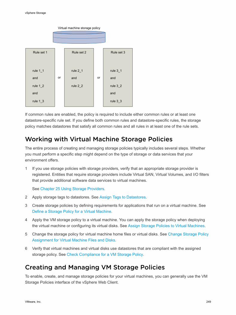
Virtual machine storage policy
Rule set 1
rule 1_1
and
rule 1_2
and
rule 1_3
or
Rule set 2
rule 2_1
and
rule 2_2
Rule set 3
rule 3_1
and
rule 3_2
and
rule 3_3
or
If common rules are enabled, the policy is required to include either common rules or at least onedatastore-specific rule set. If you define both common rules and datastore-specific rules, the storagepolicy matches datastores that satisfy all common rules and all rules in at least one of the rule sets.
Working with Virtual Machine Storage PoliciesThe entire process of creating and managing storage policies typically includes several steps. Whetheryou must perform a specific step might depend on the type of storage or data services that yourenvironment offers.
1 If you use storage policies with storage providers, verify that an appropriate storage provider isregistered. Entities that require storage providers include Virtual SAN, Virtual Volumes, and I/O filtersthat provide additional software data services to virtual machines.
See Chapter 25 Using Storage Providers.
2 Apply storage tags to datastores. See Assign Tags to Datastores.
3 Create storage policies by defining requirements for applications that run on a virtual machine. See Define a Storage Policy for a Virtual Machine.
4 Apply the VM storage policy to a virtual machine. You can apply the storage policy when deployingthe virtual machine or configuring its virtual disks. See Assign Storage Policies to Virtual Machines.
5 Change the storage policy for virtual machine home files or virtual disks. See Change Storage PolicyAssignment for Virtual Machine Files and Disks.
6 Verify that virtual machines and virtual disks use datastores that are compliant with the assignedstorage policy. See Check Compliance for a VM Storage Policy.
Creating and Managing VM Storage PoliciesTo enable, create, and manage storage policies for your virtual machines, you can generally use the VMStorage Policies interface of the vSphere Web Client.
vSphere Storage
VMware, Inc. 249
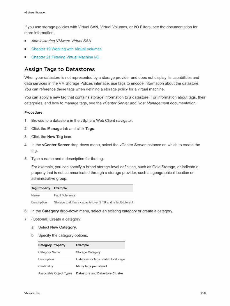
If you use storage policies with Virtual SAN, Virtual Volumes, or I/O Filters, see the documentation formore information:
n Administering VMware Virtual SAN
n Chapter 19 Working with Virtual Volumes
n Chapter 21 Filtering Virtual Machine I/O
Assign Tags to DatastoresWhen your datastore is not represented by a storage provider and does not display its capabilities anddata services in the VM Storage Polices interface, use tags to encode information about the datastore.You can reference these tags when defining a storage policy for a virtual machine.
You can apply a new tag that contains storage information to a datastore. For information about tags, theircategories, and how to manage tags, see the vCenter Server and Host Management documentation.
Procedure
1 Browse to a datastore in the vSphere Web Client navigator.
2 Click the Manage tab and click Tags.
3 Click the New Tag icon.
4 In the vCenter Server drop-down menu, select the vCenter Server instance on which to create thetag.
5 Type a name and a description for the tag.
For example, you can specify a broad storage-level definition, such as Gold Storage, or indicate aproperty that is not communicated through a storage provider, such as geographical location oradministrative group.
Tag Property Example
Name Fault Tolerance
Description Storage that has a capacity over 2 TB and is fault-tolerant
6 In the Category drop-down menu, select an existing category or create a category.
7 (Optional) Create a category:
a Select New Category.
b Specify the category options.
Category Property Example
Category Name Storage Category
Description Category for tags related to storage
Cardinality Many tags per object
Associable Object Types Datastore and Datastore Cluster
vSphere Storage
VMware, Inc. 250
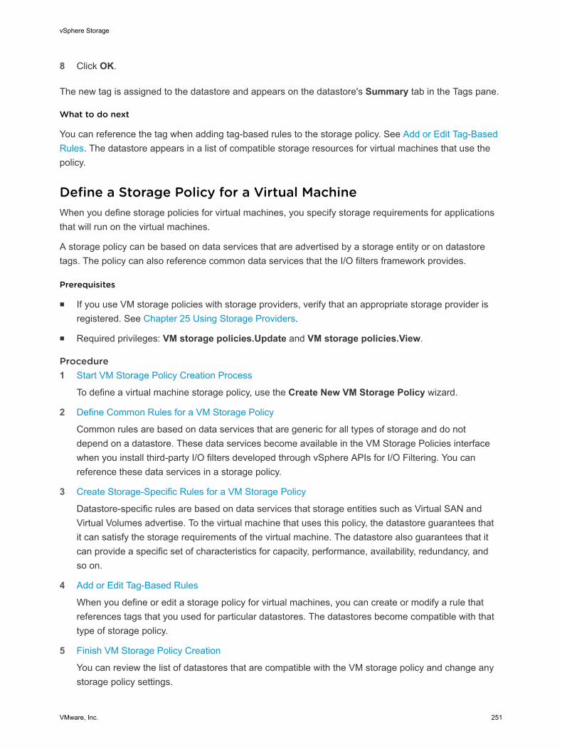
8 Click OK.
The new tag is assigned to the datastore and appears on the datastore's Summary tab in the Tags pane.
What to do next
You can reference the tag when adding tag-based rules to the storage policy. See Add or Edit Tag-BasedRules. The datastore appears in a list of compatible storage resources for virtual machines that use thepolicy.
Define a Storage Policy for a Virtual MachineWhen you define storage policies for virtual machines, you specify storage requirements for applicationsthat will run on the virtual machines.
A storage policy can be based on data services that are advertised by a storage entity or on datastoretags. The policy can also reference common data services that the I/O filters framework provides.
Prerequisites
n If you use VM storage policies with storage providers, verify that an appropriate storage provider isregistered. See Chapter 25 Using Storage Providers.
n Required privileges: VM storage policies.Update and VM storage policies.View.
Procedure1 Start VM Storage Policy Creation Process
To define a virtual machine storage policy, use the Create New VM Storage Policy wizard.
2 Define Common Rules for a VM Storage Policy
Common rules are based on data services that are generic for all types of storage and do notdepend on a datastore. These data services become available in the VM Storage Policies interfacewhen you install third-party I/O filters developed through vSphere APIs for I/O Filtering. You canreference these data services in a storage policy.
3 Create Storage-Specific Rules for a VM Storage Policy
Datastore-specific rules are based on data services that storage entities such as Virtual SAN andVirtual Volumes advertise. To the virtual machine that uses this policy, the datastore guarantees thatit can satisfy the storage requirements of the virtual machine. The datastore also guarantees that itcan provide a specific set of characteristics for capacity, performance, availability, redundancy, andso on.
4 Add or Edit Tag-Based Rules
When you define or edit a storage policy for virtual machines, you can create or modify a rule thatreferences tags that you used for particular datastores. The datastores become compatible with thattype of storage policy.
5 Finish VM Storage Policy Creation
You can review the list of datastores that are compatible with the VM storage policy and change anystorage policy settings.
vSphere Storage
VMware, Inc. 251
What to do next
You can apply this storage policy to virtual machines. If you use object-based storage, such as VirtualSAN and Virtual Volumes, you can designate this storage policy as the default.
Start VM Storage Policy Creation ProcessTo define a virtual machine storage policy, use the Create New VM Storage Policy wizard.
Procedure
1 From the vSphere Web Client Home, click Policies and Profiles > VM Storage Policies.
2 Click the Create a New VM Storage Policy icon.
3 Select the vCenter Server instance.
4 Type a name and a description for the storage policy.
Define Common Rules for a VM Storage PolicyCommon rules are based on data services that are generic for all types of storage and do not depend ona datastore. These data services become available in the VM Storage Policies interface when you installthird-party I/O filters developed through vSphere APIs for I/O Filtering. You can reference these dataservices in a storage policy.
Procedure
1 On the Common Rules page, enable common rules by selecting Use common rules in the storagepolicy.
2 From the Add rule drop-down menu, select a data service to include in the rule.
3 Select a provider of the data service.
If the same data service, for example Replication, is offered by different providers, you cannot addmore than one rule referencing this data service.
4 Specify values for the rule and click Next.
Create Storage-Specific Rules for a VM Storage PolicyDatastore-specific rules are based on data services that storage entities such as Virtual SAN and VirtualVolumes advertise. To the virtual machine that uses this policy, the datastore guarantees that it can satisfythe storage requirements of the virtual machine. The datastore also guarantees that it can provide aspecific set of characteristics for capacity, performance, availability, redundancy, and so on.
One datastore-specific rule set can include rules from only a single storage entity.
Prerequisites
If your environment includes storage entities such as Virtual SAN or Virtual Volumes, review thesefunctionalities. For information, see the Administering VMware Virtual SAN documentation and Chapter 19 Working with Virtual Volumes.
vSphere Storage
VMware, Inc. 252
Procedure
1 On the Rule Set page, select a storage provider, for example, Virtual SAN or Virtual Volumes, fromthe Rules based on data services drop-down menu.
The page expands to show data services provided by the storage resource.
2 Select a data service to include and specify its value.
Verify that the values you provide are within the range of values that the data services profile of thestorage resource advertises.
Based on your input, the storage consumption mechanism calculates the amount of space that isrequired for a virtual disk that will reside on this storage entity.
3 (Optional) Add tag-based rules.
4 Click Next.
Add or Edit Tag-Based RulesWhen you define or edit a storage policy for virtual machines, you can create or modify a rule thatreferences tags that you used for particular datastores. The datastores become compatible with that typeof storage policy.
You can add tag-based rules to a rule set that includes storage-specific rules, or create a separate ruleset with only tag-based rules. When you use tags in the policies, follow these guidelines:
n If the rule set contains other storage-specific rules, the datastore with the assigned tag must satisfy allof the rules in the rule set.
n If you add several tags from the same category within the same rule, the tags are treated asalternative constraints. Either of the tags can be satisfied.
n If you add the tags in separate rules within the same rule set, all tags must be satisfied.
Prerequisites
Create storage tags and apply them to datastores. See Assign Tags to Datastores.
Procedure
1 On the Rule Set page, add or edit a tag-based rule:
n To add a rule, click the Add tag-based rule button.
n To modify an existing rule, select the rule and click the Modify rule icon.
2 Specify a category.
3 Make a tag selection or edit an existing selection.
Datastores that use the tags that you selected are compatible with the storage policy.
vSphere Storage
VMware, Inc. 253
Finish VM Storage Policy CreationYou can review the list of datastores that are compatible with the VM storage policy and change anystorage policy settings.
Procedure
1 On the Storage Compatibility page, review the list of datastores that match this policy and click Next.
To be eligible, the datastore must satisfy at least one rule set and all rules within this set.
2 Review the storage policy settings and make changes by clicking Back to go back to the relevantpage.
3 Click Finish.
The VM storage policy appears in the list.
Delete a Virtual Machine Storage PolicyYou can delete a storage policy if you are not using it for any virtual machine or virtual disk.
Procedure
1 From the vSphere Web Client Home, click Policies and Profiles > VM Storage Policies.
2 In the VM Storage Policies interface, select a policy to delete and click the Delete a VM StoragePolicy icon ( ).
3 Click Yes.
The policy is removed from the inventory.
Edit or Clone a VM Storage PolicyIf storage requirements for virtual machines and virtual disks change, you can modify the existing storagepolicy. You can also create a copy of the existing VM storage policy by cloning it. While cloning, you canoptionally select to customize the original storage policy.
Prerequisites
Required privilege: StorageProfile.View
Procedure
1 From the vSphere Web Client Home, click Policies and Profiles > VM Storage Policies.
2 Select a storage policy, and click one of the following icons:
n Edit a VM storage policy
n Clone a VM storage policy
3 (Optional) Modify the policy and click OK.
vSphere Storage
VMware, Inc. 254
4 If editing the storage policy that is used by a virtual machine, reapply the policy to the virtual machine.
Option Description
Manually later If you select this option, the compliance status for all virtual disks and virtualmachine home objects associated with the storage policy changes to Out of Date.To update configuration and compliance, manually reapply the storage policy toall associated entities. See Reapply Virtual Machine Storage Policy.
Now Update virtual machine and compliance status immediately after editing thestorage policy.
Storage Policies and Virtual MachinesAfter you define a VM storage policy, you can apply it to a virtual machine. You apply the storage policywhen provisioning the virtual machine or configuring its virtual disks. Depending on its type andconfiguration, the policy might serve different purposes. It can select the most appropriate datastore forthe virtual machine and enforce the required level of service, or it can enable specific data services for thevirtual machine and its disks.
If you do not specify the storage policy, the system uses a default storage policy that is associated withthe datastore. If your storage requirements for the applications on the virtual machine change, you canmodify the storage policy that was originally applied to the virtual machine.
Default Storage PoliciesWhen you provision a virtual machine on an object-based datastore, such as Virtual SAN or VirtualVolumes, you must assign to the virtual machine an appropriate virtual machine storage policy that iscompatible with the datastore. This assignment guarantees the optimum placement for virtual machineobjects within the object-based storage. If you do not explicitly assign a storage policy to the virtualmachine, the system uses a default storage policy that is associated with the datastore. The default policyis also used when the policy that you assign does not include rules specific to Virtual Volumes or VirtualSAN.
The default storage policies for Virtual SAN and Virtual Volumes can be provided by VMware and user-defined. VMFS and NFS datastores do not have default policies.
Default Policies Provided by VMwareVMware provides default storage policies for Virtual SAN and virtual datastores.
Virtual SAN Default Storage Policy
The default storage policy that VMware provides is applied to all virtual machine objects that areprovisioned on a Virtual SAN datastore when you do not select any other Virtual SAN policy.
The policy that VMware provides has the following characteristics:
n You cannot delete the policy.
n The policy is editable. To edit the policy, you must have the storage policy privileges that include theview and update privileges.
vSphere Storage
VMware, Inc. 255

n When editing the policy, you cannot change the name of the policy or the Virtual SAN storageprovider specification. All other parameters including rules are editable.
n You can clone the default policy and use it as a template to create a storage policy.
n The Virtual SAN default policy is compatible only with Virtual SAN datastores.
n You can create a VM storage policy for Virtual SAN and designate it as the default.
Virtual Volumes Default Storage Policy
For Virtual Volumes, VMware provides a default storage policy that contains no rules or storagerequirements. As with Virtual SAN, this policy is applied to virtual machine objects when you do notspecify another policy for the virtual machine that you place on the virtual datastore. With the NoRequirements policy, storage arrays can determine the optimum placement for the VM objects.
The default Virtual Volumes policy that VMware provides has the following characteristics:
n You cannot delete, edit, or clone this policy.
n The Virtual Volumes default policy is compatible only with virtual datastores.
n You can create a VM storage policy for Virtual Volumes and designate it as the default.
User-Defined Default Policies for Virtual Machine StorageYou can create a VM storage policy that is compatible with Virtual SAN or Virtual Volumes, and designatethis policy as the default for Virtual SAN and virtual datastores. The user-defined default policy replacesthe default storage policy that VMware provided.
Each Virtual SAN and virtual datastore can have only one default policy at a time. However, you cancreate a single storage policy that matches multiple Virtual SAN and Virtual Volumes datastores anddesignate it as the default policy for all datastores.
When the VM storage policy becomes the default policy for a datastore, you cannot delete the policyunless you disassociate it from the datastore.
Change the Default Storage Policy for a Datastore
For Virtual Volumes and Virtual SAN datastores, VMware provides storage policies that are used as thedefault during virtual machine provisioning. You can change the default storage policy for a selectedVirtual Volumes or Virtual SAN datastore.
Prerequisites
Create a storage policy that is compatible with Virtual Volumes or Virtual SAN. You can create a policythat matches both types of storage.
Procedure
1 In the vSphere Web Client navigator, select vCenter Inventory Lists > Datastores
2 Click the datastore.
3 Click the Manage tab and click Settings.
vSphere Storage
VMware, Inc. 256
4 Click General, and click Edit in the Default Storage Policy pane.
5 From the list of available storage policies, select a policy to designate as the default and click OK.
The selected storage policy becomes the default policy for the datastore. vSphere assigns this policy toany virtual machine objects that you provision on the datastore when no other policy is selected.
Assign Storage Policies to Virtual MachinesYou can assign a VM storage policy in an initial deployment of a virtual machine or when you performother virtual machine operations, such as cloning or migrating.
This topic describes how to assign the VM storage policy when you create a virtual machine. Forinformation about other deployment methods that include cloning, deployment from a template, and soon, see the vSphere Virtual Machine Administration documentation.
You can apply the same storage policy to the virtual machine configuration file and all its virtual disks. Ifstorage requirements for your virtual disks and the configuration file are different, you can associatedifferent storage policies with the VM configuration file and the selected virtual disks.
Procedure
1 In the vSphere Web Client, start the virtual machine provisioning process and follow the appropriatesteps.
2 Assign the same storage policy to all virtual machine files and disks.
a On the Select Storage page, select a storage policy from the VM Storage Policy drop-downmenu.
Based on its configuration, the storage policy separates all datastores into compatible andincompatible sets. If the policy references data services offered by a specific storage entity, forexample, Virtual Volumes, the compatible list includes datastores that represent only that type ofstorage.
b Select an appropriate datastore from the list of compatible datastores and click Next.
The datastore becomes the destination storage resource for the virtual machine configuration file andall virtual disks.
vSphere Storage
VMware, Inc. 257

3 Change the VM storage policy for the virtual disk.
Use this option if requirements for storage placement are different for virtual disks. You can also usethis option if you must enable software data services, such as caching and replication, for your virtualdisks.
a On the Customize Hardware page, expand the New hard disk pane.
b From the VM storage policy drop-down menu, select the storage policy to assign to the virtualdisk.
c (Optional) Change the storage location of the virtual disk.
Use this option to store the virtual disk on a datastore other than the datastore where the VMconfiguration file resides.
4 Complete the virtual machine provisioning process.
After you create the virtual machine, the Summary tab displays the assigned storage policies and theircompliance status.
What to do next
If storage placement requirements for the configuration file or the virtual disks change, you can latermodify the virtual policy assignment.
Change Storage Policy Assignment for Virtual Machine Files andDisksIf your storage requirements for the applications on the virtual machine change, you can edit the storagepolicy that was originally applied to the virtual machine.
You can edit the storage policy for a powered-off or powered-on virtual machine.
When changing the VM storage policy assignment, you can apply the same storage policy to the virtualmachine configuration file and all its virtual disks. If storage requirements for your virtual disks and theconfiguration file are different, you can associate different storage policies with the VM configuration fileand the selected virtual disks.
Procedure
1 In the vSphere Web Client, browse to the virtual machine.
2 Click the Manage tab and click Policies.
3 Click Storage.
4 Click Edit VM Storage Policies.
vSphere Storage
VMware, Inc. 258
5 Specify the VM storage policy for your virtual machine.
Option Description
Apply the same storage policy to allvirtual machine objects.
a Select the policy from the VM storage policy drop-down menu.
b Click Apply to all.
Apply different storage policies to theVM home object and virtual disks.
a Select the object.
b Select the policy from the VM storage policy drop-down menu for the object.
6 Click OK.
The storage policy is assigned to the virtual machine and its disks.
Monitor Storage Compliance for Virtual MachinesWhen you associate a policy with virtual machine objects and select the datastores on which virtualmachines and virtual disks run, you can check whether virtual machines and virtual disks use datastoresthat are compliant with the policy.
If you check the compliance of a virtual machine whose host or cluster has storage policies disabled, theresult of the check is Noncompliant because the feature is disabled.
Prerequisites
To perform a compliance check for a storage policy, associate the policy with at least one virtual machineor virtual disk.
Procedure
1 From the vSphere Web Client Home, click Policies and Profiles > VM Storage Policies.
2 Double-click a storage policy.
3 Click the Monitor tab, and click VMs and Virtual Disks.
4 Click Trigger VM Storage Policy Compliance Check.
The Compliance Status column shows the storage compliance status for virtual machines and theirpolicies.
Compliance Status Description
Compliant The datastore that the virtual machine or virtual disk uses has the storage capabilities that are requiredby the policy.
Noncompliant The datastore supports specified storage requirements, but cannot currently satisfy the virtual machinestorage policy. For example, the status might become Not Compliant when physical resources that backup the datastore are unavailable or exhausted. You can bring the datastore into compliance by makingchanges in the physical configuration, for example, by adding hosts or disks to the cluster. If additionalresources satisfy the virtual machine storage policy, the status changes to Compliant.
vSphere Storage
VMware, Inc. 259
Compliance Status Description
Out of Date The status indicates that the policy has been edited, but the new requirements have not beencommunicated to the datastore where the virtual machine objects reside. To communicate the changes,reapply the policy to the objects that are out of date.
Not Applicable This storage policy references datastore capabilities that are not supported by the datastore where thevirtual machine resides.
What to do next
When you cannot bring the noncompliant datastore into compliance, migrate the files or virtual disks to acompatible datastore. See Find Compatible Storage Resource for Noncompliant Virtual Machine.
If the status is Out of Date, reapply the policy to the objects. See Reapply Virtual Machine Storage Policy.
Check Compliance for a VM Storage PolicyYou can check whether a virtual machine uses a datastore that is compatible with the storagerequirements specified in the VM storage policy.
Prerequisites
Verify that the virtual machine has a storage policy that is associated with it.
Procedure
1 In the vSphere Web Client, browse to the virtual machine.
2 From the right-click menu, select VM Policies > Check VM Storage Policy Compliance.
The system verifies the compliance.
3 Click the Summary tab for the virtual machine.
4 View the compliance status in the VM Storage Policies pane.
Compliance Status Description
Compliant The datastore that the virtual machine or virtual disk uses has the storage capabilities that are requiredby the policy.
Noncompliant The datastore supports specified storage requirements, but cannot currently satisfy the virtual machinestorage policy. For example, the status might become Not Compliant when physical resources that backup the datastore are unavailable or exhausted. You can bring the datastore into compliance by makingchanges in the physical configuration, for example, by adding hosts or disks to the cluster. If additionalresources satisfy the virtual machine storage policy, the status changes to Compliant.
Out of Date The status indicates that the policy has been edited, but the new requirements have not beencommunicated to the datastore where the virtual machine objects reside. To communicate the changes,reapply the policy to the objects that are out of date.
Not Applicable This storage policy references datastore capabilities that are not supported by the datastore where thevirtual machine resides.
vSphere Storage
VMware, Inc. 260
What to do next
When you cannot bring the noncompliant datastore into compliance, migrate the files or virtual disks to acompatible datastore. See Find Compatible Storage Resource for Noncompliant Virtual Machine.
If the status is Out of Date, reapply the policy to the objects. See Reapply Virtual Machine Storage Policy.
Find Compatible Storage Resource for Noncompliant VirtualMachineDetermine which datastore is compatible with the storage policy that is associated with your virtualmachine.
Occasionally, a storage policy that is assigned to a virtual machine can be in the noncompliant status.This status indicates that the virtual machine or its disks use datastores that are incompatible with thepolicy. You can migrate the virtual machine files and virtual disks to compatible datastores.
Use this task to determine which datastores satisfy the requirements of the policy.
Prerequisites
Verify that the VM Storage Policy Compliance field on the virtual machine Summary tab displays theNot Compliant status.
Procedure
1 In the vSphere Web Client, browse to the virtual machine.
2 Click the Summary tab.
The VM Storage Policy Compliance panel on the VM Storage Policies pane shows the Not Compliantstatus.
3 Click the policy link in the VM Storage Policies panel.
4 Click the Monitor tab and click VMs and Virtual Disks to determine which virtual machine files arenoncompliant.
5 Click Storage Compatibility.
The list of datastores that match the requirements of the policy appears.
What to do next
You can migrate the virtual machine or its disks to one of the datastores in the list.
Reapply Virtual Machine Storage PolicyAfter you edit a storage policy that is already associated with a virtual machine object, you must reapplythe policy. By reapplying the policy, you communicate new storage requirements to the datastore wherethe virtual machine object resides.
vSphere Storage
VMware, Inc. 261
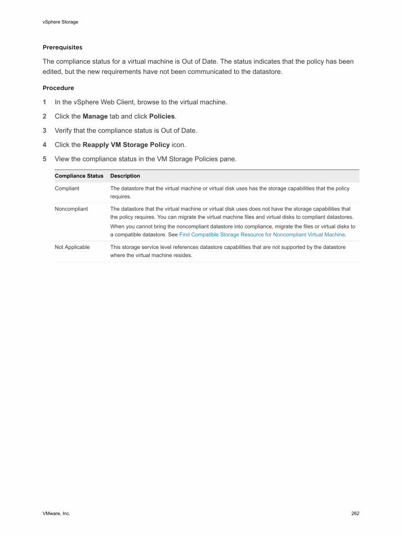
Prerequisites
The compliance status for a virtual machine is Out of Date. The status indicates that the policy has beenedited, but the new requirements have not been communicated to the datastore.
Procedure
1 In the vSphere Web Client, browse to the virtual machine.
2 Click the Manage tab and click Policies.
3 Verify that the compliance status is Out of Date.
4 Click the Reapply VM Storage Policy icon.
5 View the compliance status in the VM Storage Policies pane.
Compliance Status Description
Compliant The datastore that the virtual machine or virtual disk uses has the storage capabilities that the policyrequires.
Noncompliant The datastore that the virtual machine or virtual disk uses does not have the storage capabilities thatthe policy requires. You can migrate the virtual machine files and virtual disks to compliant datastores.
When you cannot bring the noncompliant datastore into compliance, migrate the files or virtual disks toa compatible datastore. See Find Compatible Storage Resource for Noncompliant Virtual Machine.
Not Applicable This storage service level references datastore capabilities that are not supported by the datastorewhere the virtual machine resides.
vSphere Storage
VMware, Inc. 262
Filtering Virtual Machine I/O 21vSphere APIs for I/O Filtering (VAIO) provide a framework that allows third parties to create softwarecomponents called I/O filters.
The filters can be installed on ESXi hosts and can offer additional data services to virtual machines byprocessing I/O requests that move between the guest operating system of a virtual machine and virtualdisks.
This chapter includes the following topics:
n About I/O Filters
n Using Flash Storage Devices with Cache I/O Filters
n Deploy and Configure I/O Filters in the vSphere Environment
n Managing I/O Filters
n I/O Filter Guidelines and Best Practices
About I/O FiltersI/O filters that are associated with virtual disks gain direct access to the virtual machine I/O pathregardless of the underlying storage topology.
The I/O filters are created by third-party vendors and are distributed as packages that provide an installerto deploy filter components on vCenter Server and ESXi host clusters.
After you install the I/O filter and deploy its components on the ESXi cluster, vCenter Server automaticallyconfigures and registers an I/O filter storage provider, also called a VASA provider, for each host in thecluster. The storage providers communicate with vCenter Server and make data services offered by theI/O filter visible in the VM Storage Policies interface. You can reference these data services when creatingcommon rules for a VM policy. After you associate virtual disks with this policy, the I/O filters are enabledon the virtual disks.
Types of I/O FiltersTypically, I/O filters are created by VMware partners through the vSphere APIs for I/O Filtering (VAIO)developer program. Third-party vendors can develop I/O filters for multiple purposes.
VMware, Inc. 263
In this release, the supported types of filters include the following:
n Caching. Implements a cache for virtual disk data. The filter can use a local flash storage device tocache the data and increase the IOPS and hardware utilization rates for the virtual disk. If you use thecaching filter, you might need to configure a Virtual Flash Resource.
n Replication. Replicates all write I/O operations to an external target location, such as another host orcluster.
Note You can install several filters from the same category, such as caching, on your ESXi host.However, you can have only one filter from the same category per virtual disk.
I/O Filtering ComponentsSeveral components are involved in the I/O filtering process.
The components of I/O filtering include the following:
VAIO Filter Framework A combination of user world and VMkernel infrastructure provided by ESXithat enables VMware partners to add filter plug-ins to the I/O path to andfrom virtual disks.
I/O Filter Plug-In A software component developed by VMware partners that intercepts andfilters I/O data in transit between virtual disks and guest operating systems.
CIM Provider An optional component developed by VMware partners that configures andmanages I/O filter plug-ins.
vSphere Web ClientPlug-In
An optional component developed by VMware partners. Provides vSphereadministrators with methods for communication with an I/O filter CIMprovider to receive monitoring information about the I/O filter status as wellas send configuration commands to the CIM provider to configure its I/Ofilters.
I/O Filter Daemon An optional component developed by VMware partners. It can be used asan additional service that interacts with the individual filter instancesrunning on a host. The service can establish cross-host networkcommunication channels.
The following figure illustrates the components of I/O filtering and the flow of I/Os between the guest OSand the virtual disk.
vSphere Storage
VMware, Inc. 264
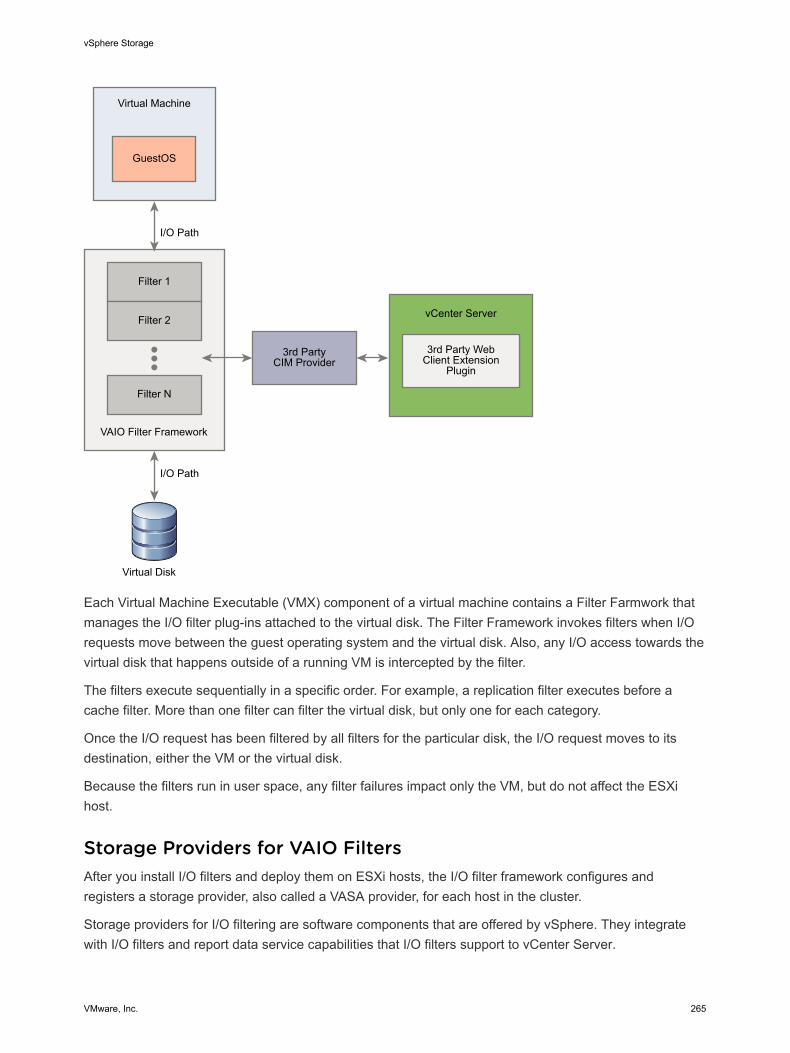
VAIO Filter Framework
Virtual Machine
GuestOS
Filter 1
Filter 2
Filter N
I/O Path
vCenter Server
Virtual Disk
3rd PartyCIM Provider
3rd Party WebClient Extension
Plugin
I/O Path
Each Virtual Machine Executable (VMX) component of a virtual machine contains a Filter Farmwork thatmanages the I/O filter plug-ins attached to the virtual disk. The Filter Framework invokes filters when I/Orequests move between the guest operating system and the virtual disk. Also, any I/O access towards thevirtual disk that happens outside of a running VM is intercepted by the filter.
The filters execute sequentially in a specific order. For example, a replication filter executes before acache filter. More than one filter can filter the virtual disk, but only one for each category.
Once the I/O request has been filtered by all filters for the particular disk, the I/O request moves to itsdestination, either the VM or the virtual disk.
Because the filters run in user space, any filter failures impact only the VM, but do not affect the ESXihost.
Storage Providers for VAIO FiltersAfter you install I/O filters and deploy them on ESXi hosts, the I/O filter framework configures andregisters a storage provider, also called a VASA provider, for each host in the cluster.
Storage providers for I/O filtering are software components that are offered by vSphere. They integratewith I/O filters and report data service capabilities that I/O filters support to vCenter Server.
vSphere Storage
VMware, Inc. 265
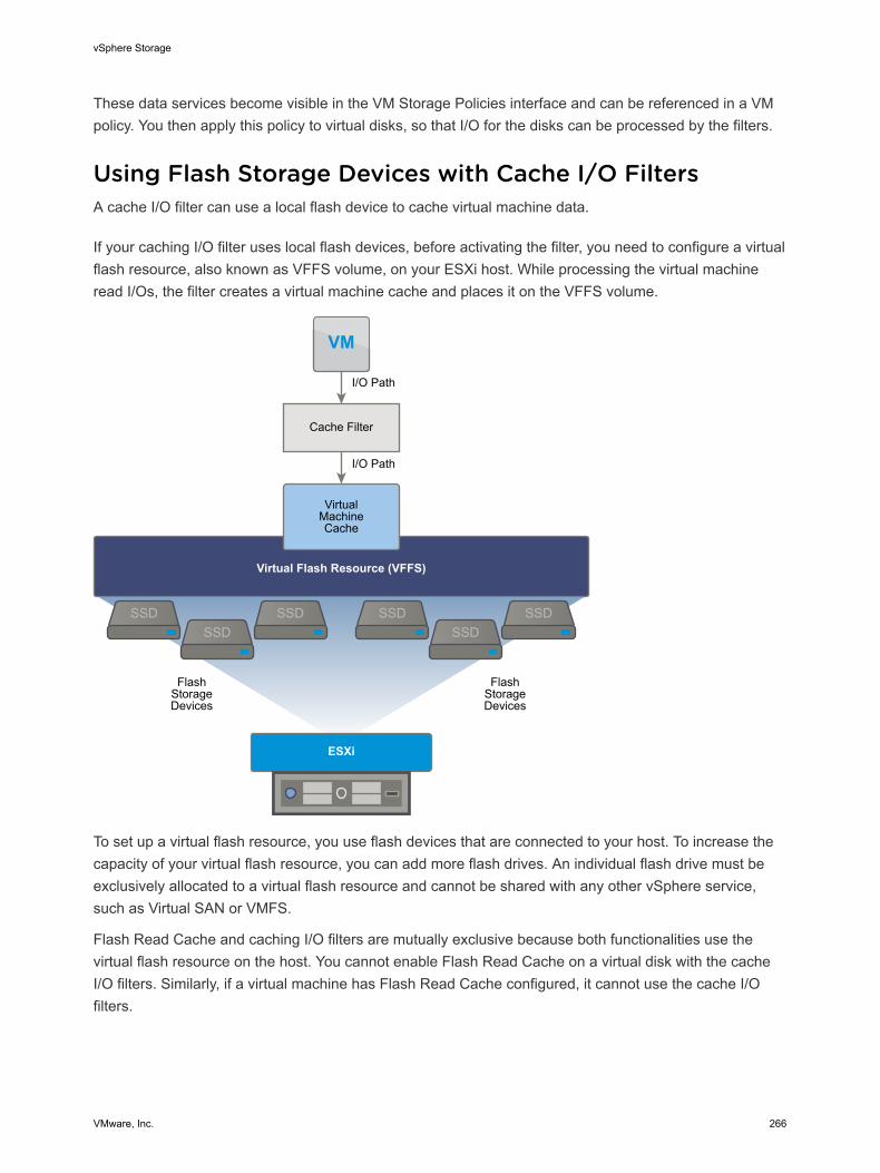
These data services become visible in the VM Storage Policies interface and can be referenced in a VMpolicy. You then apply this policy to virtual disks, so that I/O for the disks can be processed by the filters.
Using Flash Storage Devices with Cache I/O FiltersA cache I/O filter can use a local flash device to cache virtual machine data.
If your caching I/O filter uses local flash devices, before activating the filter, you need to configure a virtualflash resource, also known as VFFS volume, on your ESXi host. While processing the virtual machineread I/Os, the filter creates a virtual machine cache and places it on the VFFS volume.
SSDSSD
SSDSSDSSD
SSD
VM
FlashStorageDevices
I/O Path
I/O Path
FlashStorageDevices
Cache Filter
VirtualMachineCache
ESXi
Virtual Flash Resource (VFFS)
To set up a virtual flash resource, you use flash devices that are connected to your host. To increase thecapacity of your virtual flash resource, you can add more flash drives. An individual flash drive must beexclusively allocated to a virtual flash resource and cannot be shared with any other vSphere service,such as Virtual SAN or VMFS.
Flash Read Cache and caching I/O filters are mutually exclusive because both functionalities use thevirtual flash resource on the host. You cannot enable Flash Read Cache on a virtual disk with the cacheI/O filters. Similarly, if a virtual machine has Flash Read Cache configured, it cannot use the cache I/Ofilters.
vSphere Storage
VMware, Inc. 266
Deploy and Configure I/O Filters in the vSphereEnvironmentYou can install the I/O filters in your vSphere environment and then enable data services that the filtersprovide on your virtual machines.
Prerequisites
VMware partners create I/O filters through the vSphere APIs for I/O Filtering (VAIO) developer programand distribute them as filter packages. Packages offered as vSphere Installation Bundles (VIBs) caninclude I/O filter daemons, CIM providers, and other associated components. For information, contactyour vendor or your VMware representative.
Procedure
1 Install I/O Filters in a Cluster
You install I/O filters in an ESXi host cluster by running installers provided by vendors.
2 View I/O Filter Storage Providers
After you deploy I/O filters, a storage provider, also called a VASA provider, is automaticallyregistered for every ESXi host in the cluster. You can verify that the I/O filter storage providersappear as expected and are active.
3 Review I/O Filter Capabilities
After you install an I/O filter in your vSphere environment, capabilities and data services that the filterprovides become registered and surface in the VM Storage Policies interface. You can review theseservices and capabilities and their default values.
4 Configure Virtual Flash Resource for Caching I/O Filters
If your caching I/O filter uses local flash devices, before activating the filter, you need to configure avirtual flash resource, also known as VFFS volume, on your ESXi host.
5 Enable I/O Filter Data Services on Virtual Disks
Enabling data services that I/O filters provide is a two-step process. You create a virtual machinepolicy based on data service capabilities that I/O filters provide, and then attach this policy to avirtual machine.
What to do next
For information about troubleshooting I/O filters, see the vSphere Troubleshooting documentation.
Install I/O Filters in a ClusterYou install I/O filters in an ESXi host cluster by running installers provided by vendors.
Prerequisites
n Required privileges: Host.Configuration.Query patch.
vSphere Storage
VMware, Inc. 267

n Verify that the I/O filter solution integrates with vSphere ESX Agent Manager and is certified byVMware.
n Verify that your cluster includes ESXi 6.0 Update 1 hosts.
n Enable DRS on the cluster.
Procedure
1 Run the installer that the vendor provided.
The installer installs the appropriate I/O filter extension on vCenter Server and deploys the filtercomponents on all hosts within a cluster. You cannot install the filter on selected hosts.
2 Verify that the I/O filter components are properly installed on your ESXi hosts:
esxcli --server=server_name software vib list
The filter appears on the list of VIB packages.
View I/O Filter Storage ProvidersAfter you deploy I/O filters, a storage provider, also called a VASA provider, is automatically registered forevery ESXi host in the cluster. You can verify that the I/O filter storage providers appear as expected andare active.
Successful auto-registration of the I/O filter storage provider triggers an event at the host level. If thestorage provider fails to auto-register, the system raises an alarm on the host.
Procedure
1 Browse to vCenter Server in the vSphere Web Client navigator.
2 Click the Manage tab, and click Storage Providers.
3 Review the storage providers for I/O filters.
Review I/O Filter CapabilitiesAfter you install an I/O filter in your vSphere environment, capabilities and data services that the filterprovides become registered and surface in the VM Storage Policies interface. You can review theseservices and capabilities and their default values.
Procedure
1 From the vSphere Web Client Home, click Policies and Profiles > VM Storage Policies.
2 Click the Create a new VM storage policy icon.
3 Select the vCenter Server instance.
4 Type a name, for example Cache I/O Filter, and a description for the policy and click Next.
5 On the Common Rules page, select Use common rules in the storage policy.
6 From the Add rule drop-down menu, select an I/O filter category, for example cache.
vSphere Storage
VMware, Inc. 268
7 From the Select Value drop-down menu, select the filter, whose capabilities you want to review.
The panel expands to display data services that the I/O filter provides and corresponding defaultvalues.
Configure Virtual Flash Resource for Caching I/O FiltersIf your caching I/O filter uses local flash devices, before activating the filter, you need to configure a virtualflash resource, also known as VFFS volume, on your ESXi host.
Prerequisites
Check with your I/O filter vendor to determine whether the virtual flash resource must be enabled.
Procedure
1 In the vSphere Web Client, navigate to the host.
2 Click the Manage tab and click Settings.
3 Under Virtual Flash, select Virtual Flash Resource Management and click Add Capacity.
4 From the list of available flash drives, select one or more drives to use for the virtual flash resourceand click OK.
The virtual flash resource is created. The Device Backing area lists all the drives that you use for thevirtual flash resource.
Enable I/O Filter Data Services on Virtual DisksEnabling data services that I/O filters provide is a two-step process. You create a virtual machine policybased on data service capabilities that I/O filters provide, and then attach this policy to a virtual machine.
Prerequisites
For caching I/O filters, configure the virtual flash resource on your ESXi host.
Procedure
1 Define a VM Policy Based on I/O Filter Capabilities
To enable I/O filters for virtual machines, you must first create a virtual machine policy that lists dataservice capabilities provided by the I/O filters.
2 Assign the I/O Filter Policy to Virtual Machines
To activate data services that I/O filters provide, associate the I/O filter policy with virtual disks. Youcan assign the policy when you create or edit a virtual machine.
Define a VM Policy Based on I/O Filter CapabilitiesTo enable I/O filters for virtual machines, you must first create a virtual machine policy that lists dataservice capabilities provided by the I/O filters.
The I/O filter capabilities are displayed on the Common Rules page of the VM Storage Policies wizard.
vSphere Storage
VMware, Inc. 269
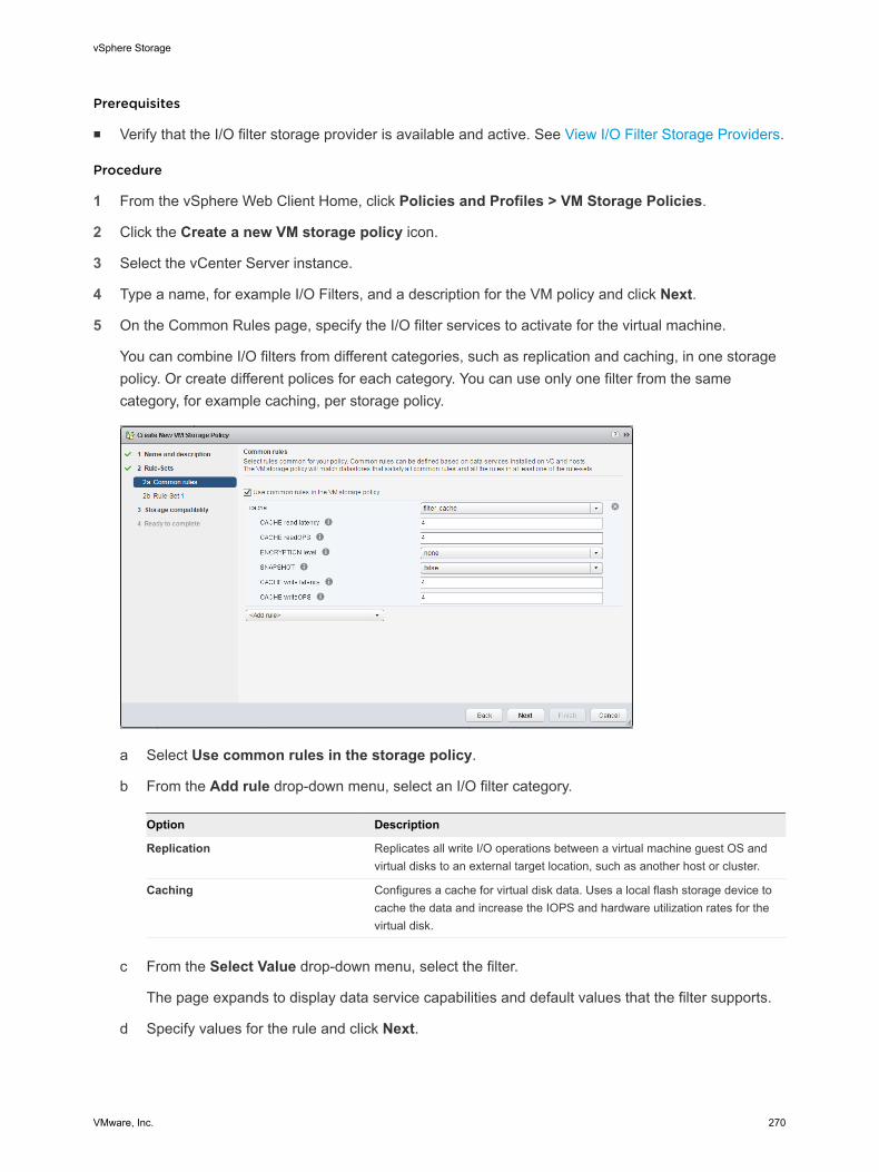
Prerequisites
n Verify that the I/O filter storage provider is available and active. See View I/O Filter Storage Providers.
Procedure
1 From the vSphere Web Client Home, click Policies and Profiles > VM Storage Policies.
2 Click the Create a new VM storage policy icon.
3 Select the vCenter Server instance.
4 Type a name, for example I/O Filters, and a description for the VM policy and click Next.
5 On the Common Rules page, specify the I/O filter services to activate for the virtual machine.
You can combine I/O filters from different categories, such as replication and caching, in one storagepolicy. Or create different polices for each category. You can use only one filter from the samecategory, for example caching, per storage policy.
a Select Use common rules in the storage policy.
b From the Add rule drop-down menu, select an I/O filter category.
Option Description
Replication Replicates all write I/O operations between a virtual machine guest OS andvirtual disks to an external target location, such as another host or cluster.
Caching Configures a cache for virtual disk data. Uses a local flash storage device tocache the data and increase the IOPS and hardware utilization rates for thevirtual disk.
c From the Select Value drop-down menu, select the filter.
The page expands to display data service capabilities and default values that the filter supports.
d Specify values for the rule and click Next.
vSphere Storage
VMware, Inc. 270
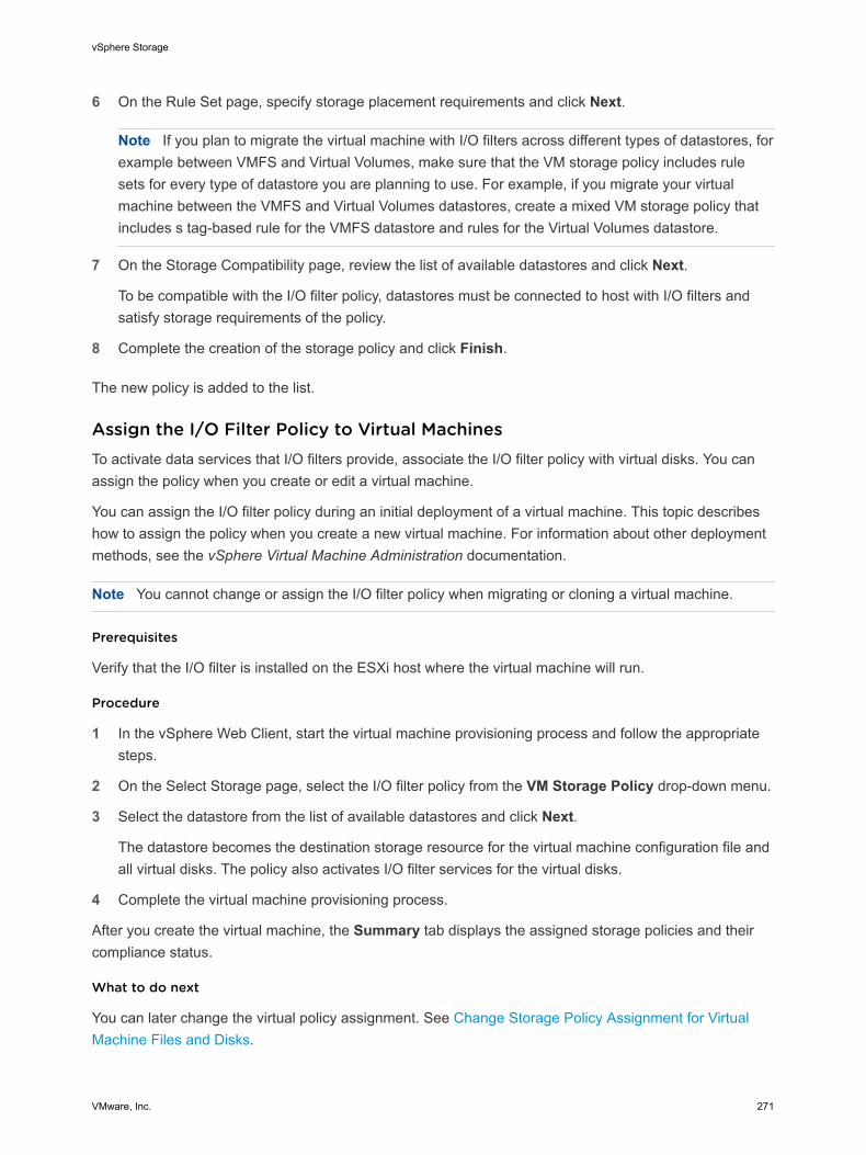
6 On the Rule Set page, specify storage placement requirements and click Next.
Note If you plan to migrate the virtual machine with I/O filters across different types of datastores, forexample between VMFS and Virtual Volumes, make sure that the VM storage policy includes rulesets for every type of datastore you are planning to use. For example, if you migrate your virtualmachine between the VMFS and Virtual Volumes datastores, create a mixed VM storage policy thatincludes s tag-based rule for the VMFS datastore and rules for the Virtual Volumes datastore.
7 On the Storage Compatibility page, review the list of available datastores and click Next.
To be compatible with the I/O filter policy, datastores must be connected to host with I/O filters andsatisfy storage requirements of the policy.
8 Complete the creation of the storage policy and click Finish.
The new policy is added to the list.
Assign the I/O Filter Policy to Virtual MachinesTo activate data services that I/O filters provide, associate the I/O filter policy with virtual disks. You canassign the policy when you create or edit a virtual machine.
You can assign the I/O filter policy during an initial deployment of a virtual machine. This topic describeshow to assign the policy when you create a new virtual machine. For information about other deploymentmethods, see the vSphere Virtual Machine Administration documentation.
Note You cannot change or assign the I/O filter policy when migrating or cloning a virtual machine.
Prerequisites
Verify that the I/O filter is installed on the ESXi host where the virtual machine will run.
Procedure
1 In the vSphere Web Client, start the virtual machine provisioning process and follow the appropriatesteps.
2 On the Select Storage page, select the I/O filter policy from the VM Storage Policy drop-down menu.
3 Select the datastore from the list of available datastores and click Next.
The datastore becomes the destination storage resource for the virtual machine configuration file andall virtual disks. The policy also activates I/O filter services for the virtual disks.
4 Complete the virtual machine provisioning process.
After you create the virtual machine, the Summary tab displays the assigned storage policies and theircompliance status.
What to do next
You can later change the virtual policy assignment. See Change Storage Policy Assignment for VirtualMachine Files and Disks.
vSphere Storage
VMware, Inc. 271
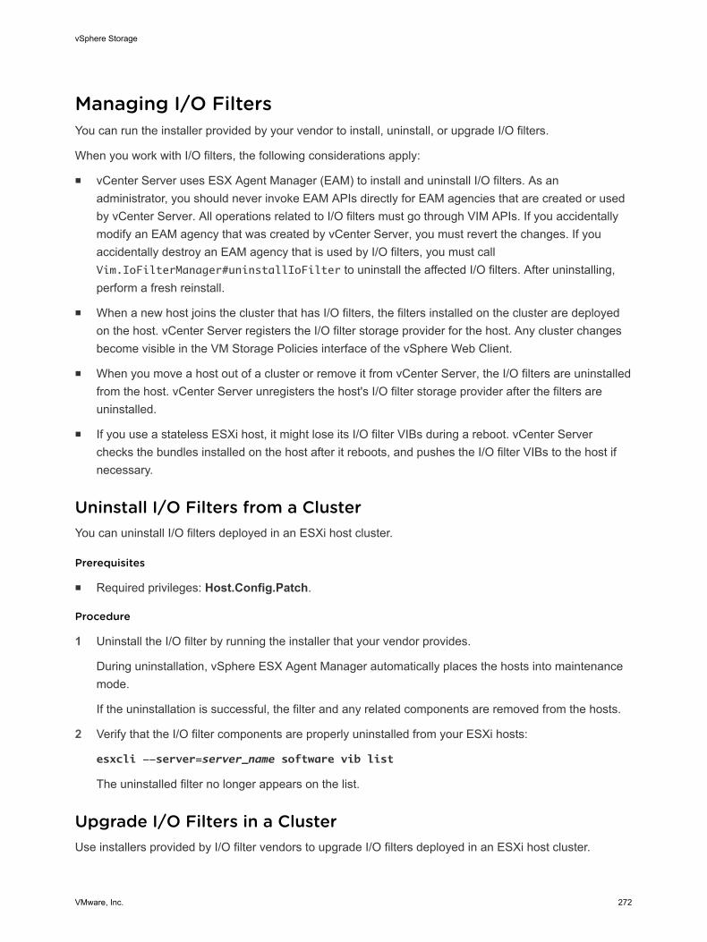
Managing I/O FiltersYou can run the installer provided by your vendor to install, uninstall, or upgrade I/O filters.
When you work with I/O filters, the following considerations apply:
n vCenter Server uses ESX Agent Manager (EAM) to install and uninstall I/O filters. As anadministrator, you should never invoke EAM APIs directly for EAM agencies that are created or usedby vCenter Server. All operations related to I/O filters must go through VIM APIs. If you accidentallymodify an EAM agency that was created by vCenter Server, you must revert the changes. If youaccidentally destroy an EAM agency that is used by I/O filters, you must callVim.IoFilterManager#uninstallIoFilter to uninstall the affected I/O filters. After uninstalling,perform a fresh reinstall.
n When a new host joins the cluster that has I/O filters, the filters installed on the cluster are deployedon the host. vCenter Server registers the I/O filter storage provider for the host. Any cluster changesbecome visible in the VM Storage Policies interface of the vSphere Web Client.
n When you move a host out of a cluster or remove it from vCenter Server, the I/O filters are uninstalledfrom the host. vCenter Server unregisters the host's I/O filter storage provider after the filters areuninstalled.
n If you use a stateless ESXi host, it might lose its I/O filter VIBs during a reboot. vCenter Serverchecks the bundles installed on the host after it reboots, and pushes the I/O filter VIBs to the host ifnecessary.
Uninstall I/O Filters from a ClusterYou can uninstall I/O filters deployed in an ESXi host cluster.
Prerequisites
n Required privileges: Host.Config.Patch.
Procedure
1 Uninstall the I/O filter by running the installer that your vendor provides.
During uninstallation, vSphere ESX Agent Manager automatically places the hosts into maintenancemode.
If the uninstallation is successful, the filter and any related components are removed from the hosts.
2 Verify that the I/O filter components are properly uninstalled from your ESXi hosts:
esxcli --server=server_name software vib list
The uninstalled filter no longer appears on the list.
Upgrade I/O Filters in a ClusterUse installers provided by I/O filter vendors to upgrade I/O filters deployed in an ESXi host cluster.
vSphere Storage
VMware, Inc. 272
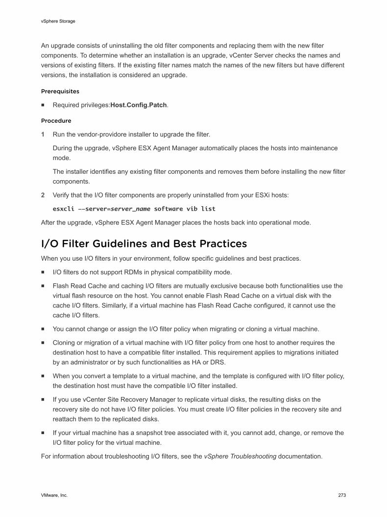
An upgrade consists of uninstalling the old filter components and replacing them with the new filtercomponents. To determine whether an installation is an upgrade, vCenter Server checks the names andversions of existing filters. If the existing filter names match the names of the new filters but have differentversions, the installation is considered an upgrade.
Prerequisites
n Required privileges:Host.Config.Patch.
Procedure
1 Run the vendor-providore installer to upgrade the filter.
During the upgrade, vSphere ESX Agent Manager automatically places the hosts into maintenancemode.
The installer identifies any existing filter components and removes them before installing the new filtercomponents.
2 Verify that the I/O filter components are properly uninstalled from your ESXi hosts:
esxcli --server=server_name software vib list
After the upgrade, vSphere ESX Agent Manager places the hosts back into operational mode.
I/O Filter Guidelines and Best PracticesWhen you use I/O filters in your environment, follow specific guidelines and best practices.
n I/O filters do not support RDMs in physical compatibility mode.
n Flash Read Cache and caching I/O filters are mutually exclusive because both functionalities use thevirtual flash resource on the host. You cannot enable Flash Read Cache on a virtual disk with thecache I/O filters. Similarly, if a virtual machine has Flash Read Cache configured, it cannot use thecache I/O filters.
n You cannot change or assign the I/O filter policy when migrating or cloning a virtual machine.
n Cloning or migration of a virtual machine with I/O filter policy from one host to another requires thedestination host to have a compatible filter installed. This requirement applies to migrations initiatedby an administrator or by such functionalities as HA or DRS.
n When you convert a template to a virtual machine, and the template is configured with I/O filter policy,the destination host must have the compatible I/O filter installed.
n If you use vCenter Site Recovery Manager to replicate virtual disks, the resulting disks on therecovery site do not have I/O filter policies. You must create I/O filter policies in the recovery site andreattach them to the replicated disks.
n If your virtual machine has a snapshot tree associated with it, you cannot add, change, or remove theI/O filter policy for the virtual machine.
For information about troubleshooting I/O filters, see the vSphere Troubleshooting documentation.
vSphere Storage
VMware, Inc. 273
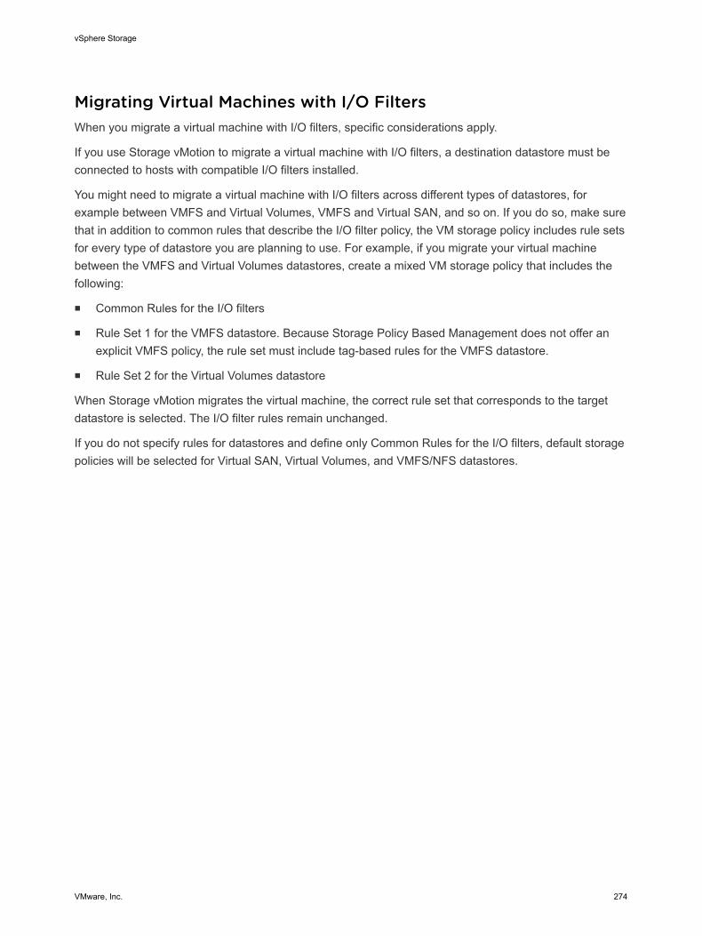
Migrating Virtual Machines with I/O FiltersWhen you migrate a virtual machine with I/O filters, specific considerations apply.
If you use Storage vMotion to migrate a virtual machine with I/O filters, a destination datastore must beconnected to hosts with compatible I/O filters installed.
You might need to migrate a virtual machine with I/O filters across different types of datastores, forexample between VMFS and Virtual Volumes, VMFS and Virtual SAN, and so on. If you do so, make surethat in addition to common rules that describe the I/O filter policy, the VM storage policy includes rule setsfor every type of datastore you are planning to use. For example, if you migrate your virtual machinebetween the VMFS and Virtual Volumes datastores, create a mixed VM storage policy that includes thefollowing:
n Common Rules for the I/O filters
n Rule Set 1 for the VMFS datastore. Because Storage Policy Based Management does not offer anexplicit VMFS policy, the rule set must include tag-based rules for the VMFS datastore.
n Rule Set 2 for the Virtual Volumes datastore
When Storage vMotion migrates the virtual machine, the correct rule set that corresponds to the targetdatastore is selected. The I/O filter rules remain unchanged.
If you do not specify rules for datastores and define only Common Rules for the I/O filters, default storagepolicies will be selected for Virtual SAN, Virtual Volumes, and VMFS/NFS datastores.
vSphere Storage
VMware, Inc. 274
VMkernel and Storage 22The VMkernel is a high-performance operating system that runs directly on the ESXi host. The VMkernelmanages most of the physical resources on the hardware, including memory, physical processors,storage, and networking controllers.
To manage storage, VMkernel has a storage subsystem that supports several Host Bus Adapters (HBAs)including parallel SCSI, SAS, Fibre Channel, FCoE, and iSCSI. These HBAs connect a wide variety ofactive-active, active-passive, and ALUA storage arrays that are certified for use with the VMkernel. Seethe vSphere Compatibility Guide for a list of the supported HBAs and storage arrays.
The primary file system that the VMkernel uses is the VMware Virtual Machine File System (VMFS).VMFS is a cluster file system designed and optimized to support large files such as virtual disks and swapfiles. The VMkernel also supports the storage of virtual disks on NFS file systems.
The storage I/O path provides virtual machines with access to storage devices through device emulation.This device emulation allows a virtual machine to access files on a VMFS or NFS file system as if theywere SCSI devices. The VMkernel provides storage virtualization functions such as the scheduling of I/Orequests from multiple virtual machines and multipathing.
In addition, VMkernel offers several Storage APIs that enable storage partners to integrate and optimizetheir products for vSphere.
The following graphic illustrates the basics of the VMkernel core, with special attention to the storagestack. Storage‐related modules reside between the logical device I/O scheduler and the adapter I/Oscheduler layers.
VMware, Inc. 275
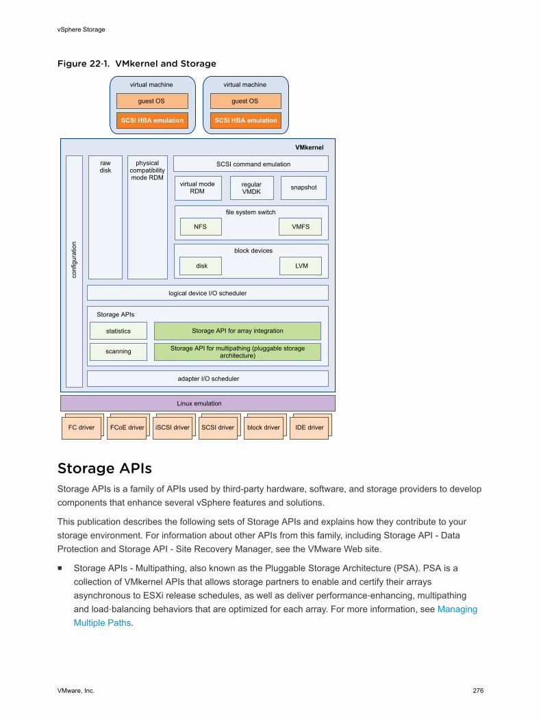
Figure 22‑1. VMkernel and Storageco
nfig
urat
ion
physicalcompatibilitymode RDM
rawdisk
SCSI command emulation
file system switch
VMFSNFS
block devices
virtual modeRDM
disk LVM
logical device I/O scheduler
Storage APIs
scanning
adapter I/O scheduler
Linux emulation
VMkernel
virtual machine
guest OS
SCSI HBA emulation
virtual machine
guest OS
SCSI HBA emulation
Storage API for multipathing (pluggable storagearchitecture)
Storage API for array integration
regularVMDK
statistics
snapshot
FC driver iSCSI driveriSCSI driver iSCSI driverSCSI driver iSCSI driverblock driver iSCSI driverIDE driverFCoE driver
Storage APIsStorage APIs is a family of APIs used by third-party hardware, software, and storage providers to developcomponents that enhance several vSphere features and solutions.
This publication describes the following sets of Storage APIs and explains how they contribute to yourstorage environment. For information about other APIs from this family, including Storage API - DataProtection and Storage API - Site Recovery Manager, see the VMware Web site.
n Storage APIs - Multipathing, also known as the Pluggable Storage Architecture (PSA). PSA is acollection of VMkernel APIs that allows storage partners to enable and certify their arraysasynchronous to ESXi release schedules, as well as deliver performance‐enhancing, multipathingand load‐balancing behaviors that are optimized for each array. For more information, see ManagingMultiple Paths.
vSphere Storage
VMware, Inc. 276
n Storage APIs - Array Integration, formerly known as VAAI, include the following APIs:
n Hardware Acceleration APIs. Allows arrays to integrate with vSphere to transparently offloadcertain storage operations to the array. This integration significantly reduces CPU overhead onthe host. See Chapter 23 Storage Hardware Acceleration.
n Array Thin Provisioning APIs. Help to monitor space use on thin-provisioned storage arrays toprevent out-of-space conditions, and to perform space reclamation. See Array Thin Provisioningand VMFS Datastores.
n Storage APIs - Storage Awareness. These vCenter Server-based APIs enable storage arrays toinform the vCenter Server about their configurations, capabilities, and storage health and events. See Chapter 25 Using Storage Providers.
vSphere Storage
VMware, Inc. 277
Storage Hardware Acceleration 23The hardware acceleration functionality enables the ESXi host to integrate with compliant storage arraysand offload specific virtual machine and storage management operations to storage hardware. With thestorage hardware assistance, your host performs these operations faster and consumes less CPU,memory, and storage fabric bandwidth.
The hardware acceleration is supported by block storage devices, Fibre Channel and iSCSI, and NASdevices.
For additional details, see the VMware knowledge base article at http://kb.vmware.com/kb/1021976.
This chapter includes the following topics:
n Hardware Acceleration Benefits
n Hardware Acceleration Requirements
n Hardware Acceleration Support Status
n Hardware Acceleration for Block Storage Devices
n Hardware Acceleration on NAS Devices
n Hardware Acceleration Considerations
Hardware Acceleration BenefitsWhen the hardware acceleration functionality is supported, the host can get hardware assistance andperform several tasks faster and more efficiently.
The host can get assistance with the following activities:
n Migrating virtual machines with Storage vMotion
n Deploying virtual machines from templates
n Cloning virtual machines or templates
n VMFS clustered locking and metadata operations for virtual machine files
n Provisioning thick virtual disks
n Creating fault-tolerant virtual machines
n Creating and cloning thick disks on NFS datastores
VMware, Inc. 278
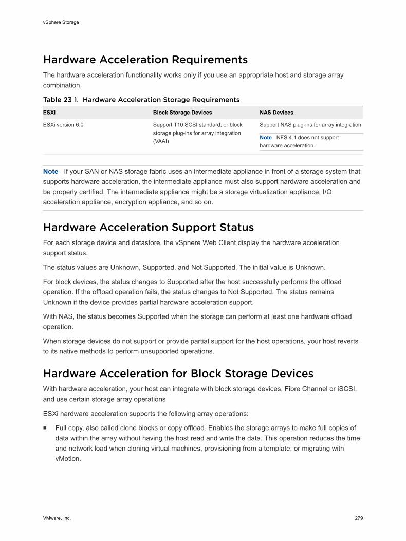
Hardware Acceleration RequirementsThe hardware acceleration functionality works only if you use an appropriate host and storage arraycombination.
Table 23‑1. Hardware Acceleration Storage Requirements
ESXi Block Storage Devices NAS Devices
ESXi version 6.0 Support T10 SCSI standard, or blockstorage plug-ins for array integration(VAAI)
Support NAS plug-ins for array integration
Note NFS 4.1 does not supporthardware acceleration.
Note If your SAN or NAS storage fabric uses an intermediate appliance in front of a storage system thatsupports hardware acceleration, the intermediate appliance must also support hardware acceleration andbe properly certified. The intermediate appliance might be a storage virtualization appliance, I/Oacceleration appliance, encryption appliance, and so on.
Hardware Acceleration Support StatusFor each storage device and datastore, the vSphere Web Client display the hardware accelerationsupport status.
The status values are Unknown, Supported, and Not Supported. The initial value is Unknown.
For block devices, the status changes to Supported after the host successfully performs the offloadoperation. If the offload operation fails, the status changes to Not Supported. The status remainsUnknown if the device provides partial hardware acceleration support.
With NAS, the status becomes Supported when the storage can perform at least one hardware offloadoperation.
When storage devices do not support or provide partial support for the host operations, your host revertsto its native methods to perform unsupported operations.
Hardware Acceleration for Block Storage DevicesWith hardware acceleration, your host can integrate with block storage devices, Fibre Channel or iSCSI,and use certain storage array operations.
ESXi hardware acceleration supports the following array operations:
n Full copy, also called clone blocks or copy offload. Enables the storage arrays to make full copies ofdata within the array without having the host read and write the data. This operation reduces the timeand network load when cloning virtual machines, provisioning from a template, or migrating withvMotion.
vSphere Storage
VMware, Inc. 279
n Block zeroing, also called write same. Enables storage arrays to zero out a large number of blocks toprovide newly allocated storage, free of previously written data. This operation reduces the time andnetwork load when creating virtual machines and formatting virtual disks.
n Hardware assisted locking, also called atomic test and set (ATS). Supports discrete virtual machinelocking without use of SCSI reservations. This operation allows disk locking per sector, instead of theentire LUN as with SCSI reservations.
Check with your vendor for the hardware acceleration support. Certain storage arrays require that youactivate the support on the storage side.
On your host, the hardware acceleration is enabled by default. If your storage does not support thehardware acceleration, you can disable it.
In addition to hardware acceleration support, ESXi includes support for array thin provisioning. Forinformation, see Array Thin Provisioning and VMFS Datastores.
Disable Hardware Acceleration for Block Storage DevicesOn your host, the hardware acceleration for block storage devices is enabled by default. You can use thevSphere Web Client advanced settings to disable the hardware acceleration operations.
As with any advanced settings, before you disable the hardware acceleration, consult with the VMwaresupport team.
Procedure
1 Browse to the host in the vSphere Web Client navigator.
2 Click the Manage tab, and click Settings.
3 Under System, click Advanced System Settings.
4 Change the value for any of the options to 0 (disabled):
n VMFS3.HardwareAcceleratedLocking
n DataMover.HardwareAcceleratedMove
n DataMover.HardwareAcceleratedInit
Managing Hardware Acceleration on Block Storage DevicesTo integrate with the block storage arrays and to benefit from the array hardware operations, vSphereuses the ESXi extensions referred to as Storage APIs - Array Integration, formerly called VAAI.
In the vSphere 5.x and later releases, these extensions are implemented as the T10 SCSI basedcommands. As a result, with the devices that support the T10 SCSI standard, your ESXi host cancommunicate directly and does not require the VAAI plug-ins.
If the device does not support T10 SCSI or provides partial support, ESXi reverts to using the VAAI plug-ins, installed on your host, or uses a combination of the T10 SCSI commands and plug-ins. The VAAIplug-ins are vendor-specific and can be either VMware or partner developed. To manage the VAAIcapable device, your host attaches the VAAI filter and vendor-specific VAAI plug-in to the device.
vSphere Storage
VMware, Inc. 280
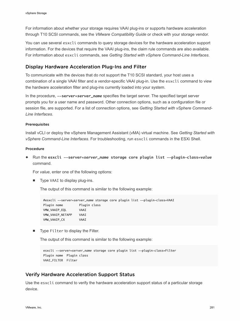
For information about whether your storage requires VAAI plug-ins or supports hardware accelerationthrough T10 SCSI commands, see the VMware Compatibility Guide or check with your storage vendor.
You can use several esxcli commands to query storage devices for the hardware acceleration supportinformation. For the devices that require the VAAI plug-ins, the claim rule commands are also available.For information about esxcli commands, see Getting Started with vSphere Command-Line Interfaces.
Display Hardware Acceleration Plug-Ins and FilterTo communicate with the devices that do not support the T10 SCSI standard, your host uses acombination of a single VAAI filter and a vendor-specific VAAI plug-in. Use the esxcli command to viewthe hardware acceleration filter and plug-ins currently loaded into your system.
In the procedure, --server=server_name specifies the target server. The specified target serverprompts you for a user name and password. Other connection options, such as a configuration file orsession file, are supported. For a list of connection options, see Getting Started with vSphere Command-Line Interfaces.
Prerequisites
Install vCLI or deploy the vSphere Management Assistant (vMA) virtual machine. See Getting Started withvSphere Command-Line Interfaces. For troubleshooting, run esxcli commands in the ESXi Shell.
Procedure
u Run the esxcli --server=server_name storage core plugin list --plugin-class=valuecommand.
For value, enter one of the following options:
n Type VAAI to display plug-ins.
The output of this command is similar to the following example:
#esxcli --server=server_name storage core plugin list --plugin-class=VAAI
Plugin name Plugin class
VMW_VAAIP_EQL VAAI
VMW_VAAIP_NETAPP VAAI
VMW_VAAIP_CX VAAI
n Type Filter to display the Filter.
The output of this command is similar to the following example:
esxcli --server=server_name storage core plugin list --plugin-class=Filter
Plugin name Plugin class
VAAI_FILTER Filter
Verify Hardware Acceleration Support StatusUse the esxcli command to verify the hardware acceleration support status of a particular storagedevice.
vSphere Storage
VMware, Inc. 281
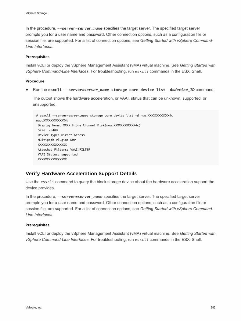
In the procedure, --server=server_name specifies the target server. The specified target serverprompts you for a user name and password. Other connection options, such as a configuration file orsession file, are supported. For a list of connection options, see Getting Started with vSphere Command-Line Interfaces.
Prerequisites
Install vCLI or deploy the vSphere Management Assistant (vMA) virtual machine. See Getting Started withvSphere Command-Line Interfaces. For troubleshooting, run esxcli commands in the ESXi Shell.
Procedure
u Run the esxcli --server=server_name storage core device list -d=device_ID command.
The output shows the hardware acceleration, or VAAI, status that can be unknown, supported, orunsupported.
# esxcli --server=server_name storage core device list -d naa.XXXXXXXXXXXX4c
naa.XXXXXXXXXXXX4c
Display Name: XXXX Fibre Channel Disk(naa.XXXXXXXXXXXX4c)
Size: 20480
Device Type: Direct-Access
Multipath Plugin: NMP
XXXXXXXXXXXXXXXX
Attached Filters: VAAI_FILTER
VAAI Status: supported
XXXXXXXXXXXXXXXX
Verify Hardware Acceleration Support DetailsUse the esxcli command to query the block storage device about the hardware acceleration support thedevice provides.
In the procedure, --server=server_name specifies the target server. The specified target serverprompts you for a user name and password. Other connection options, such as a configuration file orsession file, are supported. For a list of connection options, see Getting Started with vSphere Command-Line Interfaces.
Prerequisites
Install vCLI or deploy the vSphere Management Assistant (vMA) virtual machine. See Getting Started withvSphere Command-Line Interfaces. For troubleshooting, run esxcli commands in the ESXi Shell.
vSphere Storage
VMware, Inc. 282
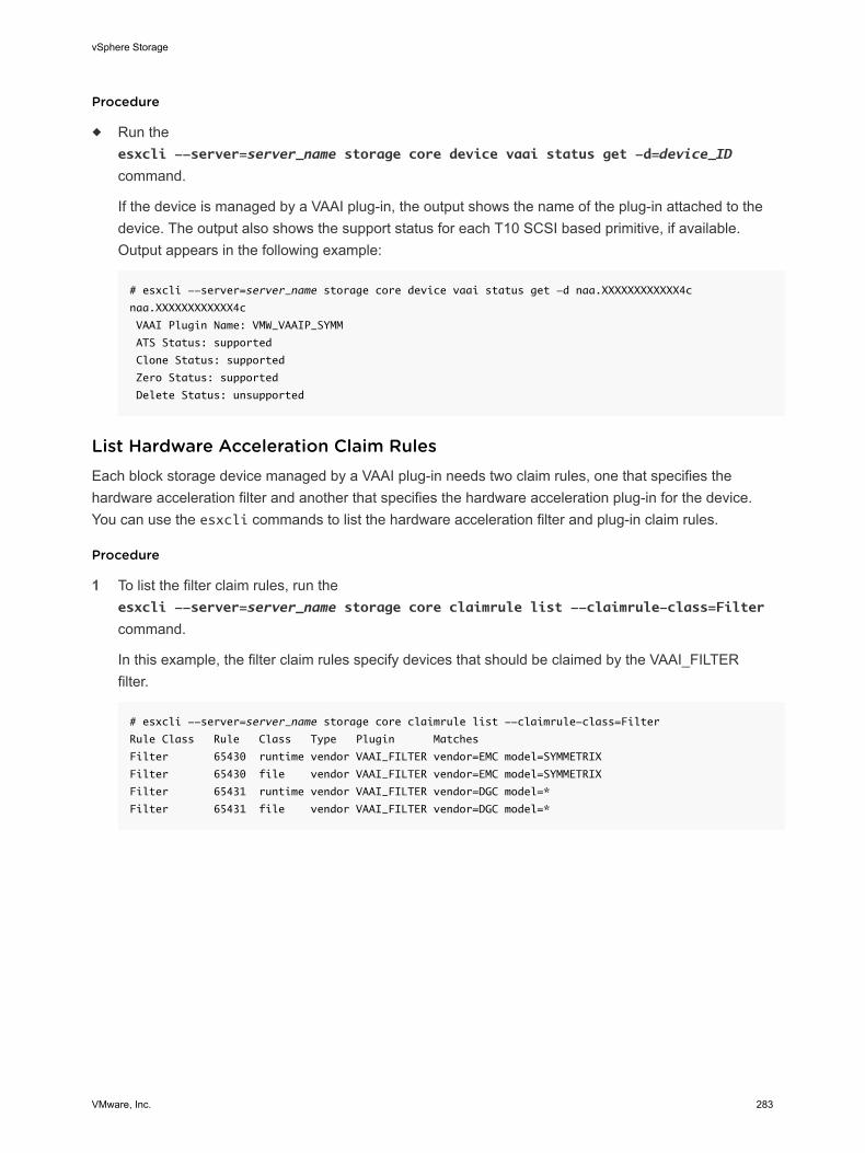
Procedure
u Run theesxcli --server=server_name storage core device vaai status get -d=device_ID
command.
If the device is managed by a VAAI plug-in, the output shows the name of the plug-in attached to thedevice. The output also shows the support status for each T10 SCSI based primitive, if available.Output appears in the following example:
# esxcli --server=server_name storage core device vaai status get -d naa.XXXXXXXXXXXX4c
naa.XXXXXXXXXXXX4c
VAAI Plugin Name: VMW_VAAIP_SYMM
ATS Status: supported
Clone Status: supported
Zero Status: supported
Delete Status: unsupported
List Hardware Acceleration Claim RulesEach block storage device managed by a VAAI plug-in needs two claim rules, one that specifies thehardware acceleration filter and another that specifies the hardware acceleration plug-in for the device.You can use the esxcli commands to list the hardware acceleration filter and plug-in claim rules.
Procedure
1 To list the filter claim rules, run theesxcli --server=server_name storage core claimrule list --claimrule-class=Filter
command.
In this example, the filter claim rules specify devices that should be claimed by the VAAI_FILTERfilter.
# esxcli --server=server_name storage core claimrule list --claimrule-class=Filter
Rule Class Rule Class Type Plugin Matches
Filter 65430 runtime vendor VAAI_FILTER vendor=EMC model=SYMMETRIX
Filter 65430 file vendor VAAI_FILTER vendor=EMC model=SYMMETRIX
Filter 65431 runtime vendor VAAI_FILTER vendor=DGC model=*
Filter 65431 file vendor VAAI_FILTER vendor=DGC model=*
vSphere Storage
VMware, Inc. 283
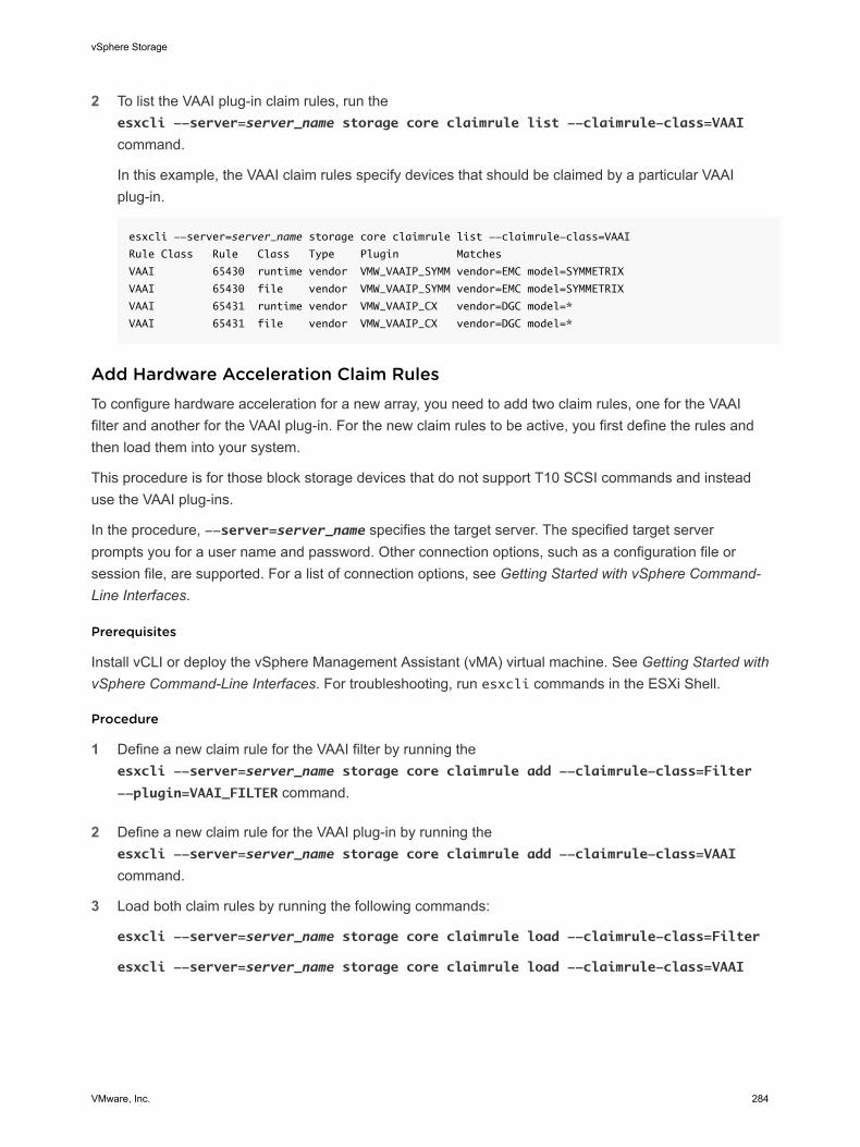
2 To list the VAAI plug-in claim rules, run theesxcli --server=server_name storage core claimrule list --claimrule-class=VAAI
command.
In this example, the VAAI claim rules specify devices that should be claimed by a particular VAAIplug-in.
esxcli --server=server_name storage core claimrule list --claimrule-class=VAAI
Rule Class Rule Class Type Plugin Matches
VAAI 65430 runtime vendor VMW_VAAIP_SYMM vendor=EMC model=SYMMETRIX
VAAI 65430 file vendor VMW_VAAIP_SYMM vendor=EMC model=SYMMETRIX
VAAI 65431 runtime vendor VMW_VAAIP_CX vendor=DGC model=*
VAAI 65431 file vendor VMW_VAAIP_CX vendor=DGC model=*
Add Hardware Acceleration Claim RulesTo configure hardware acceleration for a new array, you need to add two claim rules, one for the VAAIfilter and another for the VAAI plug-in. For the new claim rules to be active, you first define the rules andthen load them into your system.
This procedure is for those block storage devices that do not support T10 SCSI commands and insteaduse the VAAI plug-ins.
In the procedure, --server=server_name specifies the target server. The specified target serverprompts you for a user name and password. Other connection options, such as a configuration file orsession file, are supported. For a list of connection options, see Getting Started with vSphere Command-Line Interfaces.
Prerequisites
Install vCLI or deploy the vSphere Management Assistant (vMA) virtual machine. See Getting Started withvSphere Command-Line Interfaces. For troubleshooting, run esxcli commands in the ESXi Shell.
Procedure
1 Define a new claim rule for the VAAI filter by running theesxcli --server=server_name storage core claimrule add --claimrule-class=Filter
--plugin=VAAI_FILTER command.
2 Define a new claim rule for the VAAI plug-in by running theesxcli --server=server_name storage core claimrule add --claimrule-class=VAAI
command.
3 Load both claim rules by running the following commands:
esxcli --server=server_name storage core claimrule load --claimrule-class=Filter
esxcli --server=server_name storage core claimrule load --claimrule-class=VAAI
vSphere Storage
VMware, Inc. 284
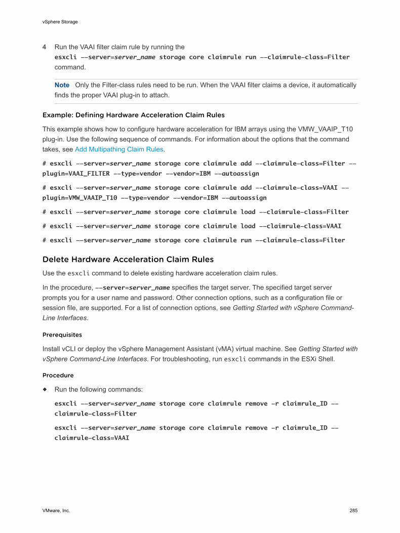
4 Run the VAAI filter claim rule by running theesxcli --server=server_name storage core claimrule run --claimrule-class=Filter
command.
Note Only the Filter-class rules need to be run. When the VAAI filter claims a device, it automaticallyfinds the proper VAAI plug-in to attach.
Example: Defining Hardware Acceleration Claim Rules
This example shows how to configure hardware acceleration for IBM arrays using the VMW_VAAIP_T10plug-in. Use the following sequence of commands. For information about the options that the commandtakes, see Add Multipathing Claim Rules.
# esxcli --server=server_name storage core claimrule add --claimrule-class=Filter --
plugin=VAAI_FILTER --type=vendor --vendor=IBM --autoassign
# esxcli --server=server_name storage core claimrule add --claimrule-class=VAAI --
plugin=VMW_VAAIP_T10 --type=vendor --vendor=IBM --autoassign
# esxcli --server=server_name storage core claimrule load --claimrule-class=Filter
# esxcli --server=server_name storage core claimrule load --claimrule-class=VAAI
# esxcli --server=server_name storage core claimrule run --claimrule-class=Filter
Delete Hardware Acceleration Claim RulesUse the esxcli command to delete existing hardware acceleration claim rules.
In the procedure, --server=server_name specifies the target server. The specified target serverprompts you for a user name and password. Other connection options, such as a configuration file orsession file, are supported. For a list of connection options, see Getting Started with vSphere Command-Line Interfaces.
Prerequisites
Install vCLI or deploy the vSphere Management Assistant (vMA) virtual machine. See Getting Started withvSphere Command-Line Interfaces. For troubleshooting, run esxcli commands in the ESXi Shell.
Procedure
u Run the following commands:
esxcli --server=server_name storage core claimrule remove -r claimrule_ID --
claimrule-class=Filter
esxcli --server=server_name storage core claimrule remove -r claimrule_ID --
claimrule-class=VAAI
vSphere Storage
VMware, Inc. 285
Hardware Acceleration on NAS DevicesHardware acceleration allows ESXi hosts to integrate with NAS devices and use several hardwareoperations that NAS storage provides. Hardware acceleration uses VMware vSphere Storage APIs forArray Integration (VAAI) to enable communication between the hosts and storage devices.
The APIs define a set of storage primitives that enable the host to offload certain storage operations tothe array. The following list shows the supported NAS operations:
n Full File Clone. Enables NAS device to clone virtual disk files. This operation is similar to the VMFSblock cloning, except that NAS devices clone entire files instead of file segments.
n Reserve Space. Enables storage arrays to allocate space for a virtual disk file in thick format.
Typically, when you create a virtual disk on an NFS datastore, the NAS server determines theallocation policy. The default allocation policy on most NAS servers is thin and does not guaranteebacking storage to the file. However, the reserve space operation can instruct the NAS device to usevendor-specific mechanisms to reserve space for a virtual disk. As a result, you can create thickvirtual disks on the NFS datastore.
n Native Snapshot Support. Allows creation of virtual machine snapshots to be offloaded to the array.
n Extended Statistics. Enables visibility to space usage on NAS devices and is useful for ThinProvisioning.
With NAS storage devices, the hardware acceleration integration is implemented through vendor-specificNAS plug-ins. These plug-ins are typically created by vendors and are distributed as VIB packagesthrough a web page. No claim rules are required for the NAS plug-ins to function.
There are several tools available for installing and upgrading VIB packages. They include the esxclicommands and vSphere Update Manager. For more information, see the vSphere Upgrade and Installingand Administering VMware vSphere Update Manager documentation.
Install NAS Plug-InInstall vendor-distributed hardware acceleration NAS plug-ins on your host.
This topic provides an example for a VIB package installation using the esxcli command. For moredetails, see the vSphere Upgrade documentation.
In the procedure, --server=server_name specifies the target server. The specified target serverprompts you for a user name and password. Other connection options, such as a configuration file orsession file, are supported. For a list of connection options, see Getting Started with vSphere Command-Line Interfaces.
Prerequisites
Install vCLI or deploy the vSphere Management Assistant (vMA) virtual machine. See Getting Started withvSphere Command-Line Interfaces. For troubleshooting, run esxcli commands in the ESXi Shell.
vSphere Storage
VMware, Inc. 286
Procedure
1 Place your host into the maintenance mode.
2 Set the host acceptance level:
esxcli --server=server_name software acceptance set --level=value
The command controls which VIB package is allowed on the host. The value can be one of thefollowing:n VMwareCertified
n VMwareAccepted
n PartnerSupported
n CommunitySupported
3 Install the VIB package:
esxcli --server=server_name software vib install -v|--viburl=URL
The URL specifies the URL to the VIB package to install. http:, https:, ftp:, and file: are supported.
4 Verify that the plug-in is installed:
esxcli --server=server_name software vib list
5 Reboot your host for the installation to take effect.
Uninstall NAS Plug-InsTo uninstall a NAS plug-in, remove the VIB package from your host.
This topic discusses how to uninstall a VIB package using the esxcli command. For more details, seethe vSphere Upgrade documentation.
In the procedure, --server=server_name specifies the target server. The specified target serverprompts you for a user name and password. Other connection options, such as a configuration file orsession file, are supported. For a list of connection options, see Getting Started with vSphere Command-Line Interfaces.
Prerequisites
Install vCLI or deploy the vSphere Management Assistant (vMA) virtual machine. See Getting Started withvSphere Command-Line Interfaces. For troubleshooting, run esxcli commands in the ESXi Shell.
Procedure
1 Uninstall the plug-in:
esxcli --server=server_name software vib remove -n|--vibname=name
The name is the name of the VIB package to remove.
2 Verify that the plug-in is removed:
esxcli --server=server_name software vib list
vSphere Storage
VMware, Inc. 287
3 Reboot your host for the change to take effect.
Update NAS Plug-InsUpgrade hardware acceleration NAS plug-ins on your host when a storage vendor releases a new plug-inversion.
In the procedure, --server=server_name specifies the target server. The specified target serverprompts you for a user name and password. Other connection options, such as a configuration file orsession file, are supported. For a list of connection options, see Getting Started with vSphere Command-Line Interfaces.
Prerequisites
This topic discusses how to update a VIB package using the esxcli command. For more details, see thevSphere Upgrade documentation.
Install vCLI or deploy the vSphere Management Assistant (vMA) virtual machine. See Getting Started withvSphere Command-Line Interfaces. For troubleshooting, run esxcli commands in the ESXi Shell.
Procedure
1 Upgrade to a new plug-in version:
esxcli --server=server_name software vib update -v|--viburl=URL
The URL specifies the URL to the VIB package to update. http:, https:, ftp:, and file: are supported.
2 Verify that the correct version is installed:
esxcli --server=server_name software vib list
3 Reboot the host.
Verify Hardware Acceleration Status for NASIn addition to the client, you can use the esxcli command to verify the hardware acceleration status ofthe NAS device.
In the procedure, --server=server_name specifies the target server. The specified target serverprompts you for a user name and password. Other connection options, such as a configuration file orsession file, are supported. For a list of connection options, see Getting Started with vSphere Command-Line Interfaces.
Prerequisites
Install vCLI or deploy the vSphere Management Assistant (vMA) virtual machine. See Getting Started withvSphere Command-Line Interfaces. For troubleshooting, run esxcli commands in the ESXi Shell.
Procedure
u Run the esxcli --server=server_name storage nfs list command.
The Hardware Acceleration column in the output shows the status.
vSphere Storage
VMware, Inc. 288
Hardware Acceleration ConsiderationsWhen you use the hardware acceleration functionality, certain considerations apply.
Several reasons might cause a hardware-accelerated operation to fail.
For any primitive that the array does not implement, the array returns an error. The error triggers the ESXihost to attempt the operation using its native methods.
The VMFS data mover does not leverage hardware offloads and instead uses software data movementwhen one of the following occurs:
n The source and destination VMFS datastores have different block sizes.
n The source file type is RDM and the destination file type is non-RDM (regular file).
n The source VMDK type is eagerzeroedthick and the destination VMDK type is thin.
n The source or destination VMDK is in sparse or hosted format.
n The source virtual machine has a snapshot.
n The logical address and transfer length in the requested operation are not aligned to the minimumalignment required by the storage device. All datastores created with the vSphere Web Client arealigned automatically.
n The VMFS has multiple LUNs or extents, and they are on different arrays.
Hardware cloning between arrays, even within the same VMFS datastore, does not work.
vSphere Storage
VMware, Inc. 289
Storage Thick and ThinProvisioning 24vSphere supports two models of storage provisioning, thick provisioning and thin provisioning.
Thick provisioning It is a traditional model of storage provisioning. With thick provisioning,large amount of storage space is provided in advance in anticipation offuture storage needs. However, the space might remain unused causingunderutilization of storage capacity.
Thin provisioning This method contrast with thick provisioning and helps you eliminatestorage underutilization problems by allocating storage space in a flexibleon-demand manner. With ESXi, you can use two models of thinprovisioning, array‐level and virtual disk‐level.
This chapter includes the following topics:
n Storage Over-Subscription
n Virtual Disk Thin Provisioning
n Array Thin Provisioning and VMFS Datastores
Storage Over-SubscriptionThin provisioning allows you to report more virtual storage space than there is real physical capacity. Thisdiscrepancy can lead to storage over-subscription, also called over-provisioning.
When you use thin provisioning, you should monitor actual storage usage to avoid conditions when yourun out of physical storage space.
Virtual Disk Thin ProvisioningWhen you create a virtual machine, a certain amount of storage space on a datastore is provisioned tovirtual disk files.
By default, ESXi offers a traditional storage provisioning method for virtual machines. With this method,you first estimate how much storage the virtual machine will need for its entire life cycle. You thenprovision a fixed amount of storage space to its virtual disk in advance, for example, 40GB, and have theentire provisioned space committed to the virtual disk. A virtual disk that immediately occupies the entireprovisioned space is a thick disk.
VMware, Inc. 290
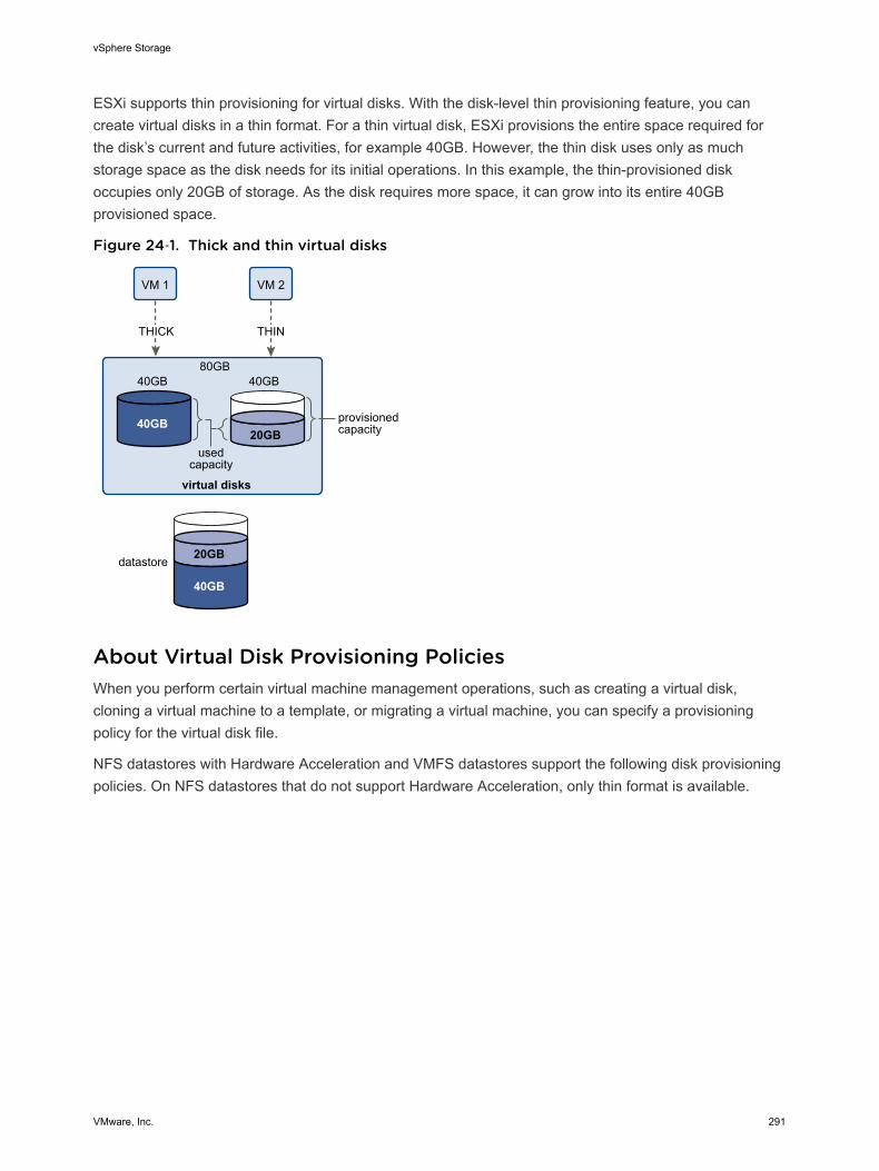
ESXi supports thin provisioning for virtual disks. With the disk-level thin provisioning feature, you cancreate virtual disks in a thin format. For a thin virtual disk, ESXi provisions the entire space required forthe disk’s current and future activities, for example 40GB. However, the thin disk uses only as muchstorage space as the disk needs for its initial operations. In this example, the thin-provisioned diskoccupies only 20GB of storage. As the disk requires more space, it can grow into its entire 40GBprovisioned space.
Figure 24‑1. Thick and thin virtual disks
VM 2VM 1
40GB
40GB 40GB80GB
20GB
THICK THIN
virtual disks
provisionedcapacity
datastore
usedcapacity
20GB
40GB
About Virtual Disk Provisioning PoliciesWhen you perform certain virtual machine management operations, such as creating a virtual disk,cloning a virtual machine to a template, or migrating a virtual machine, you can specify a provisioningpolicy for the virtual disk file.
NFS datastores with Hardware Acceleration and VMFS datastores support the following disk provisioningpolicies. On NFS datastores that do not support Hardware Acceleration, only thin format is available.
vSphere Storage
VMware, Inc. 291
You can use Storage vMotion or cross-host Storage vMotion to transform virtual disks from one format toanother.
Thick Provision LazyZeroed
Creates a virtual disk in a default thick format. Space required for the virtualdisk is allocated when the disk is created. Data remaining on the physicaldevice is not erased during creation, but is zeroed out on demand at a latertime on first write from the virtual machine. Virtual machines do not readstale data from the physical device.
Thick Provision EagerZeroed
A type of thick virtual disk that supports clustering features such as FaultTolerance. Space required for the virtual disk is allocated at creation time.In contrast to the thick provision lazy zeroed format, the data remaining onthe physical device is zeroed out when the virtual disk is created. It mighttake longer to create virtual disks in this format than to create other types ofdisks.
Thin Provision Use this format to save storage space. For the thin disk, you provision asmuch datastore space as the disk would require based on the value thatyou enter for the virtual disk size. However, the thin disk starts small and atfirst, uses only as much datastore space as the disk needs for its initialoperations. If the thin disk needs more space later, it can grow to itsmaximum capacity and occupy the entire datastore space provisioned to it.
Thin provisioning is the fastest method to create a virtual disk because itcreates a disk with just the header information. It does not allocate or zeroout storage blocks. Storage blocks are allocated and zeroed out when theyare first accessed.
Note If a virtual disk supports clustering solutions such as Fault Tolerance,do not make the disk thin.
You can manually inflate the thin disk, so that it occupies the entireprovisioned space. If physical storage space is exhausted and the thinprovisioned disk cannot grow, the virtual machine becomes unusable.
Create Thin Provisioned Virtual DisksTo save storage space, you can create a virtual disk in thin provisioned format. The thin provisionedvirtual disk starts small and grows as more disk space is required. You can create thin disks only on thedatastores that support disk-level thin provisioning.
This procedure assumes that you are creating a new virtual machine. For information, see the vSphereVirtual Machine Administration documentation.
Procedure
1 Right-click any inventory object that is a valid parent object of a virtual machine, such as a datacenter, folder, cluster, resource pool, or host, and select New Virtual Machine.
vSphere Storage
VMware, Inc. 292
2 Select Create a new virtual machine and click Next.
3 Follow the steps required to create a virtual machine.
4 On the Customize Hardware page, click the Virtual Hardware tab.
5 Click the New Hard Disk triangle to expand the hard disk options.
6 (Optional) Adjust the default disk size.
With a thin virtual disk, the disk size value shows how much space is provisioned and guaranteed tothe disk. At the beginning, the virtual disk might not use the entire provisioned space and the actualstorage usage value could be less than the size of the virtual disk.
7 Select Thin Provision for Disk Provisioning.
8 Finish virtual machine creation.
You created a virtual machine with a disk in thin format.
What to do next
If you created a virtual disk in the thin format, you can later inflate it to its full size.
View Virtual Machine Storage ResourcesYou can view how datastore storage space is allocated for your virtual machines.
Storage Usage shows how much datastore space is occupied by virtual machine files, includingconfiguration and log files, snapshots, virtual disks, and so on. When the virtual machine is running, theused storage space also includes swap files.
For virtual machines with thin disks, the actual storage usage value might be less than the size of thevirtual disk.
Procedure
1 In the vSphere Web Client, browse to the virtual machine.
2 Double-click the virtual machine and click the Summary tab.
3 Review the storage usage information in the upper right area of the Summary tab.
Determine the Disk Format of a Virtual MachineYou can determine whether your virtual disk is in thick or thin format.
Procedure
1 In the vSphere Web Client, browse to the virtual machine.
2 Right-click the virtual machine and select Edit Settings.
3 Click the Virtual Hardware tab.
vSphere Storage
VMware, Inc. 293
4 Click the Hard Disk triangle to expand the hard disk options.
The Type text box shows the format of your virtual disk.
What to do next
If your virtual disk is in the thin format, you can inflate it to its full size.
Inflate Thin Virtual DisksIf you created a virtual disk in the thin format, you can convert the thin disk to a virtual disk in thickprovision format.
You use the datastore browser to inflate the virtual disk.
Prerequisites
n Make sure that the datastore where the virtual machine resides has enough space.
n Make sure that the virtual disk is thin.
n Remove snapshots.
n Power off your virtual machine.
Procedure
1 Navigate to the folder of the virtual disk you want to inflate.
a In the vSphere Web Client, browse to the virtual machine.
b Double-click the virtual machine to display its information.
c Click the Related Objects tab and click Datastores.
The datastore that stores the virtual machine files is listed.
d Select the datastore and click the Navigate to the datastore file browser icon.
The datastore browser displays contents of the datastore.
2 Open the virtual machine folder and browse to the virtual disk file that you want to convert.
The file has the .vmdk extension and is marked with the virtual disk ( ) icon.
3 Right-click the virtual disk file and select Inflate.
Note The option might not be available if the virtual disk is thick or when the virtual machine isrunning.
The inflated virtual disk occupies the entire datastore space originally provisioned to it.
Handling Datastore Over-SubscriptionBecause the provisioned space for thin disks can be greater than the committed space, a datastore over-subscription can occur, which results in the total provisioned space for the virtual machine disks on thedatastore being greater than the actual capacity.
vSphere Storage
VMware, Inc. 294
Over-subscription can be possible because usually not all virtual machines with thin disks need the entireprovisioned datastore space simultaneously. However, if you want to avoid over-subscribing thedatastore, you can set up an alarm that notifies you when the provisioned space reaches a certainthreshold.
For information on setting alarms, see the vCenter Server and Host Management documentation.
If your virtual machines require more space, the datastore space is allocated on a first come first servedbasis. When the datastore runs out of space, you can add more physical storage and increase thedatastore.
See Increase VMFS Datastore Capacity.
Array Thin Provisioning and VMFS DatastoresYou can use thin provisioned storage arrays with ESXi.
Traditional LUNs that arrays present to the ESXi host, are thick-provisioned. The entire physical spaceneeded to back each LUN is allocated in advance.
ESXi also supports thin-provisioned LUNs. When a LUN is thin-provisioned, the storage array reports theLUN's logical size, which might be larger than the real physical capacity backing that LUN.
A VMFS datastore that you deploy on the thin-provisioned LUN can detect only the logical size of theLUN. For example, if the array reports 2TB of storage while in reality the array provides only 1TB, thedatastore considers 2TB to be the LUN's size. As the datastore grows, it cannot determine whether theactual amount of physical space is still sufficient for its needs.
However, when you use the Storage APIs - Array Integration, the host can integrate with physical storageand become aware of underlying thin-provisioned LUNs and their space usage.
Using thin provision integration, your host can perform these tasks:
n Monitor the use of space on thin-provisioned LUNs to avoid running out of physical space. As yourdatastore grows or if you use Storage vMotion to migrate virtual machines to a thin-provisioned LUN,the host communicates with the LUN and warns you about breaches in physical space and about out-of-space conditions.
n Inform the array about the datastore space that is freed when files are deleted or removed from thedatastore by Storage vMotion. The array can then reclaim the freed blocks of space.
Note ESXi does not support enabling and disabling of thin provisioning on a storage device.
RequirementsTo use the thin provision reporting feature, your host and storage array must meet the followingrequirements:
n ESXi version 5.0 or later.
n Storage array has appropriate firmware that supports T10-based Storage APIs - Array Integration(Thin Provisioning). For information, contact your storage provider and check the HCL.
vSphere Storage
VMware, Inc. 295
Space Usage MonitoringThe thin provision integration functionality helps you to monitor the space usage on thin-provisionedLUNs and to avoid running out of space.
The following sample flow demonstrates how the ESXi host and the storage array interact to generatebreach of space and out-of-space warnings for a datastore with underlying thin-provisioned LUN. Thesame mechanism applies when you use Storage vMotion to migrate virtual machines to the thin-provisioned LUN.
1 Using storage-specific tools, your storage administrator provisions a thin LUN and sets a softthreshold limit that, when reached, triggers an alert. This step is vendor-specific.
2 Using the vSphere Web Client, you create a VMFS datastore on the thin-provisioned LUN. Thedatastore spans the entire logical size that the LUN reports.
3 As the space used by the datastore increases and reaches the specified soft threshold, the followingactions take place:
a The storage array reports the breach to your host.
b Your host triggers a warning alarm for the datastore.
You can contact the storage administrator to request more physical space or use Storage vMotionto evacuate your virtual machines before the LUN runs out of capacity.
4 If no space is left to allocate to the thin-provisioned LUN, the following actions take place:
a The storage array reports out-of-space condition to your host.
Caution In certain cases, when a LUN becomes full, it might go offline or get unmapped fromthe host.
b The host pauses virtual machines and generates an out-of-space alarm.
You can resolve the permanent out-of-space condition by requesting more physical space fromthe storage administrator.
Identify Thin-Provisioned Storage DevicesUse the esxcli command to verify whether a particular storage device is thin-provisioned.
In the procedure, --server=server_name specifies the target server. The specified target serverprompts you for a user name and password. Other connection options, such as a configuration file orsession file, are supported. For a list of connection options, see Getting Started with vSphere Command-Line Interfaces.
Prerequisites
Install vCLI or deploy the vSphere Management Assistant (vMA) virtual machine. See Getting Started withvSphere Command-Line Interfaces. For troubleshooting, run esxcli commands in the ESXi Shell.
vSphere Storage
VMware, Inc. 296
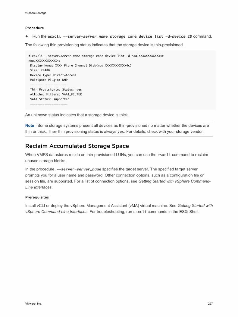
Procedure
u Run the esxcli --server=server_name storage core device list -d=device_ID command.
The following thin provisioning status indicates that the storage device is thin-provisioned.
# esxcli --server=server_name storage core device list -d naa.XXXXXXXXXXXX4c
naa.XXXXXXXXXXXX4c
Display Name: XXXX Fibre Channel Disk(naa.XXXXXXXXXXXX4c)
Size: 20480
Device Type: Direct-Access
Multipath Plugin: NMP
---------------------
Thin Provisioning Status: yes
Attached Filters: VAAI_FILTER
VAAI Status: supported
---------------------
An unknown status indicates that a storage device is thick.
Note Some storage systems present all devices as thin-provisioned no matter whether the devices arethin or thick. Their thin provisioning status is always yes. For details, check with your storage vendor.
Reclaim Accumulated Storage SpaceWhen VMFS datastores reside on thin-provisioned LUNs, you can use the esxcli command to reclaimunused storage blocks.
In the procedure, --server=server_name specifies the target server. The specified target serverprompts you for a user name and password. Other connection options, such as a configuration file orsession file, are supported. For a list of connection options, see Getting Started with vSphere Command-Line Interfaces.
Prerequisites
Install vCLI or deploy the vSphere Management Assistant (vMA) virtual machine. See Getting Started withvSphere Command-Line Interfaces. For troubleshooting, run esxcli commands in the ESXi Shell.
vSphere Storage
VMware, Inc. 297
Procedure
u Reclaim unused storage blocks on the VMFS5 datastore for the thin-provisioned device by runningthe following command:
esxcli --server=server_name storage vmfs unmap --volume-label=volume_label|--
volume-uuid=volume_uuid --reclaim-unit=number
The command takes these options:
Option Description
-l|--volume-label=volume_label The label of the VMFS volume to unmap. This is a mandatory argument. If youspecify this argument, do not use -u|--volume-uuid=volume_uuid.
-u|--volume-uuid=volume_uuid The UUID of the VMFS volume to unmap. This is a mandatory argument. If youspecify this argument, do not use -l|--volume-label=volume_label.
-n|--reclaim-unit=number Number of VMFS blocks to unmap per iteration. This is an optional argument. If itis not specified, the command uses the default value of 200.
What to do next
Important For additional details, see the VMware knowledge base article at http://kb.vmware.com/kb/2014849.
vSphere Storage
VMware, Inc. 298
Using Storage Providers 25A storage provider is a software component that is either offered by vSphere or is developed by a thirdparty through the vSphere APIs for Storage Awareness (VASA). Storage providers integrate with a varietyof storage entities that include external physical storage and storage abstractions, such as Virtual SANand Virtual Volumes. Storage providers can also support software solutions, for example, I/O filtersdeveloped through vSphere APIs for I/O Filtering.
Generally, vSphere uses storage providers to obtain information about storage topology, status, andstorage data services offered in your environment. This information appears in the vSphere Web Client.The information helps you to make appropriate decision about virtual machine placement and to monitoryour storage environment.
The third-party storage provider is typically installed on the storage side and acts as a storage awarenessservice in the vSphere environment.
To find out whether your storage supports the storage provider plug-ins, contact your storage vendor. Ifyour storage supports third-party storage providers, use the vSphere Web Client to register and manageeach storage provider component.
Built-in storage providers typically run on the ESXi hosts and do not require registration. For example, thestorage provider that supports Virtual SAN becomes registered automatically when you enable VirtualSAN. For more information, see the Administering VMware Virtual SAN documentation.
This chapter includes the following topics:
n Storage Providers and Storage Data Representation
n Storage Provider Requirements and Considerations
n Storage Status Reporting
n Register Storage Providers
n Securing Communication with Storage Providers
n View Storage Provider Information
n Unregister Storage Providers
n Update Storage Providers
VMware, Inc. 299
Storage Providers and Storage Data RepresentationvCenter Server and ESXi communicate with the storage provider to obtain information that the storageprovider collects from underlying physical and software-defined storage, or from available I/O filters.vCenter Server can then display the storage data in the vSphere Web Client.
Information that the storage provider supplies can be divided into the following categories:
n Storage data services and capabilities. This type of information is essential for such functionalities asVirtual SAN, Virtual Volumes, and I/O filters. The storage provider collects information about dataservices that are offered by underlying storage entities or available I/O filters.
You reference these data services when you define storage requirements for virtual machines andvirtual disks in a storage policy. Depending on your environment, the storage policy ensuresappropriate storage placement for a virtual machine or enables specific data services for virtual disks.For details, see Understanding Virtual Machine Storage Policies.
n Storage status. This category includes reporting about status of various storage entities. It alsoincludes alarms and events for notifying about configuration changes.
This type of information can help you troubleshoot storage connectivity and performance problems. Itcan also help you to correlate array-generated events and alarms to corresponding performance andload changes on the array.
n Storage DRS information. For distributed resource scheduling (DRS) on block devices or file systems.Storage providers supply additional information about storage system, so that decisions made byStorage DRS are compatible with resource management decisions internal to the storage systems.
Storage Provider Requirements and ConsiderationsWhen you use the storage provider functionality, certain requirements and considerations apply.
Typically, vendors are responsible for supplying storage providers that integrate with vSphere. Storageproviders are implemented through VMware APIs for Storage Awareness (VASA). The VASA architectureextends the Storage Monitoring Service (SMS), shipped with vSphere, and defines a set of functions thatvCenter Server and ESXi hosts can use to communicate with VASA Providers.
To use storage providers, follow these requirements:
n Make sure that every storage provider you use is certified by VMware and properly deployed. Forinformation about deploying the storage providers, contact your storage vendor or check the VMwareCompatibility Guide.
n Make sure that the storage provider is compatible with the vSphere version. See VMwareCompatibility Guide
When you use storage providers, the following considerations apply:
n Both block storage and file system storage devices can use storage providers.
n Storage providers can run anywhere, except vCenter Server. Typically, the third-party storageprovider runs on either the storage array service processor or on a standalone host.
vSphere Storage
VMware, Inc. 300
n Multiple vCenter Servers can simultaneously connect to a single instance of a storage provider.
n A single vCenter Server can simultaneously connect to multiple different storage providers. It ispossible to have a different storage provider for each type of physical storage device available to yourhost.
Storage Status ReportingIf you use storage providers, the vCenter Server can collect status characteristics for physical storagedevices and display this information in the vSphere Web Client.
The status information includes events and alarms.
n Events indicate important changes in the storage configuration. Such changes might include creationand deletion of a LUN, or a LUN becoming inaccessible due to LUN masking.
n Alarms indicate a change in storage system availability. For example, when you use profile-basedstorage management, you can specify virtual machine storage requirements. When changes tounderlying storage occur that might violate the storage requirements of the virtual machine, an alarmgets triggered.
For more information about events and alarms, see the vSphere Monitoring and Performancedocumentation.
Thin-provisioned LUNs have special reporting requirements. For information about space monitoring onthin-provisioned LUNs, see Array Thin Provisioning and VMFS Datastores.
Register Storage ProvidersTo establish a connection between vCenter Server and a storage provider, you must register the storageprovider. Make sure to register a separate storage provider for each host in a cluster.
Note If you use Virtual SAN, the storage providers for Virtual SAN are registered and appear on the listof storage providers automatically. Virtual SAN does not support manual registration of storage providers.See the Administering VMware Virtual SAN documentation.
Prerequisites
Verify that the storage provider component is installed on the storage side and obtain its credentials fromyour storage administrator.
Procedure
1 Browse to vCenter Server in the vSphere Web Client navigator.
2 Click the Manage tab, and click Storage Providers.
3 Click the Register a new storage provider icon.
4 Type connection information for the storage provider, including the name, URL, and credentials.
vSphere Storage
VMware, Inc. 301
5 (Optional) To direct vCenter Server to the storage provider certificate, select the Use storageprovider certificate option and specify the certificate's location.
If you do not select this option, a thumbprint of the certificate is displayed. You can check thethumbprint and approve it.
6 Click OK to complete the registration.
vCenter Server has registered the storage provider and established a secure SSL connection with it.
What to do next
If your storage provider fails to register, see the VMware Knowledge Base article http://kb.vmware.com/kb/2079087. For problems with Virtual SAN storage provider registration, see http://kb.vmware.com/kb/2105018.
Securing Communication with Storage ProvidersTo communicate with a storage provider, the vCenter Server uses a secure SSL connection. The SSLauthentication mechanism requires that both parties, the vCenter Server and the storage provider,exchange SSL certificates and add them to their truststores.
The vCenter Server can add the storage provider certificate to its truststore as part of the storage providerinstallation. If the certificate is not added during the installation, use one of the following methods to add itwhen registering the storage provider:
n Direct the vCenter Server to the storage provider certificate. In the New Storage Provider dialog box,select the Use storage provider certificate option and specify the certificate's location.
n Use a thumbprint of the storage provider certificate. If you do not direct the vCenter Server to use theprovider certificate, the certificate thumbprint is displayed. You can check the thumbprint and approveit. The vCenter Server adds the certificate to the truststore and proceeds with the connection.
The storage provider adds the vCenter Server certificate to its truststore when the vCenter Server firstconnects to the provider.
View Storage Provider InformationAfter you register a storage provider component with the vCenter Server, the Storage provider appears onthe storage providers list.
View general Storage provider information and details for each storage component.
Procedure
1 Browse to vCenter Server in the vSphere Web Client navigator.
2 Click the Manage tab, and click Storage Providers.
vSphere Storage
VMware, Inc. 302
3 In the Storage Providers list, view the storage provider components registered with the vCenterServer.
The list shows general vendor information including the name, URL, and the time of the last viewrefresh.
4 To display additional details, select a specific storage provider from the list.
The details include storage array vendors and array models that the provider supports.
Note A single Storage provider can support storage arrays from multiple different vendors.
Unregister Storage ProvidersUnregister storage providers that you do not need.
Caution You cannot manually unregister storage providers supplied by VMware, such as Virtual SANstorage providers.
Procedure
1 Browse to vCenter Server in the vSphere Web Client navigator.
2 Click the Manage tab, and click Storage Providers.
3 From the list of storage providers, select the one you want to unregister and click the Unregister thestorage provider icon.
vCenter Server terminates the connection and removes the storage provider from its configuration.
Update Storage ProvidersThe vCenter Server periodically updates storage data in its database. The updates are partial and reflectonly those storage changes that storage providers communicate to the vCenter Server. When needed,you can perform a full database synchronisation for the selected storage provider.
Procedure
1 Browse to vCenter Server in the vSphere Web Client navigator.
2 Click the Manage tab, and click Storage Providers.
3 From the list, select the storage provider that you want to synchronise with and click the Rescan thestorage provider icon.
The vSphere Web Client updates the storage data for the provider.
vSphere Storage
VMware, Inc. 303
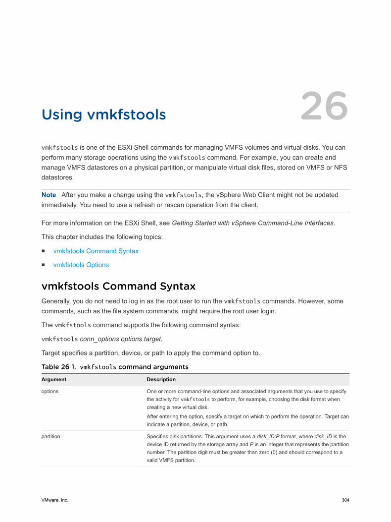
Using vmkfstools 26vmkfstools is one of the ESXi Shell commands for managing VMFS volumes and virtual disks. You canperform many storage operations using the vmkfstools command. For example, you can create andmanage VMFS datastores on a physical partition, or manipulate virtual disk files, stored on VMFS or NFSdatastores.
Note After you make a change using the vmkfstools, the vSphere Web Client might not be updatedimmediately. You need to use a refresh or rescan operation from the client.
For more information on the ESXi Shell, see Getting Started with vSphere Command-Line Interfaces.
This chapter includes the following topics:
n vmkfstools Command Syntax
n vmkfstools Options
vmkfstools Command SyntaxGenerally, you do not need to log in as the root user to run the vmkfstools commands. However, somecommands, such as the file system commands, might require the root user login.
The vmkfstools command supports the following command syntax:
vmkfstools conn_options options target.
Target specifies a partition, device, or path to apply the command option to.
Table 26‑1. vmkfstools command arguments
Argument Description
options One or more command-line options and associated arguments that you use to specifythe activity for vmkfstools to perform, for example, choosing the disk format whencreating a new virtual disk.
After entering the option, specify a target on which to perform the operation. Target canindicate a partition, device, or path.
partition Specifies disk partitions. This argument uses a disk_ID:P format, where disk_ID is thedevice ID returned by the storage array and P is an integer that represents the partitionnumber. The partition digit must be greater than zero (0) and should correspond to avalid VMFS partition.
VMware, Inc. 304
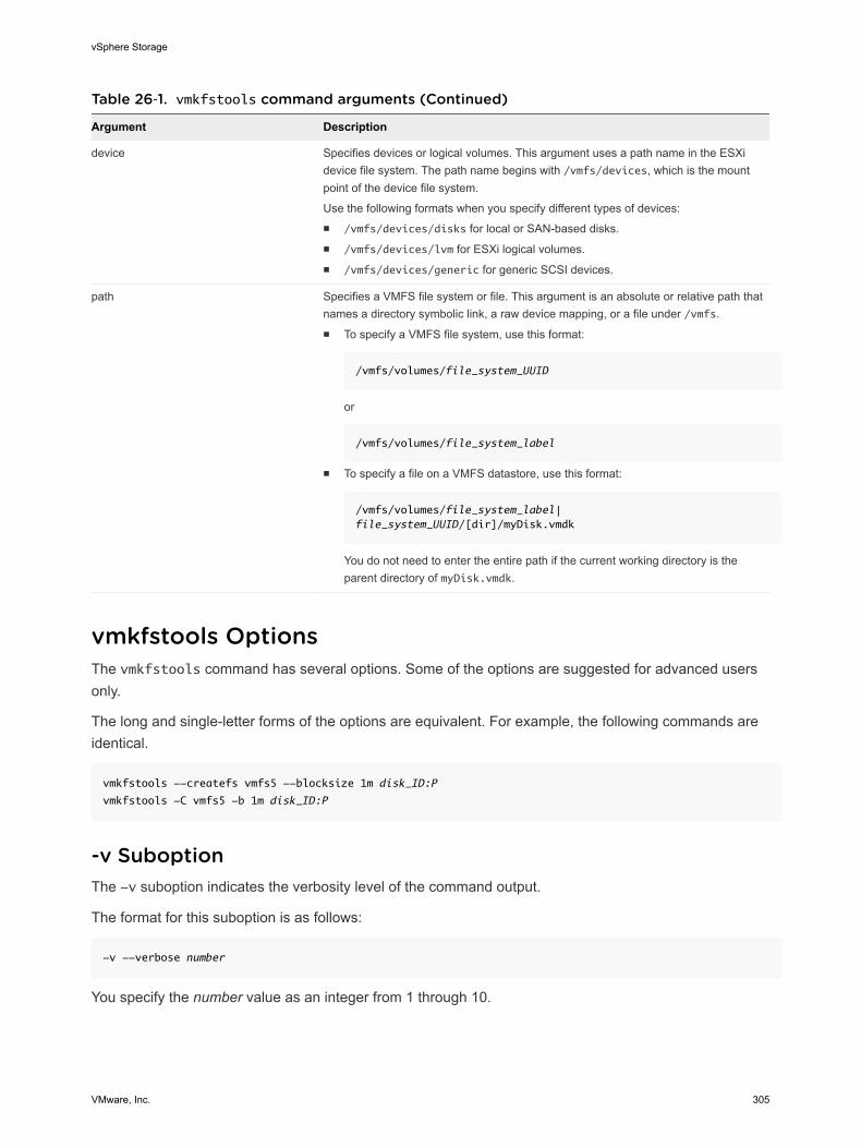
Table 26‑1. vmkfstools command arguments (Continued)
Argument Description
device Specifies devices or logical volumes. This argument uses a path name in the ESXidevice file system. The path name begins with /vmfs/devices, which is the mountpoint of the device file system.
Use the following formats when you specify different types of devices:n /vmfs/devices/disks for local or SAN-based disks.n /vmfs/devices/lvm for ESXi logical volumes.n /vmfs/devices/generic for generic SCSI devices.
path Specifies a VMFS file system or file. This argument is an absolute or relative path thatnames a directory symbolic link, a raw device mapping, or a file under /vmfs.n To specify a VMFS file system, use this format:
/vmfs/volumes/file_system_UUID
or
/vmfs/volumes/file_system_label
n To specify a file on a VMFS datastore, use this format:
/vmfs/volumes/file_system_label|file_system_UUID/[dir]/myDisk.vmdk
You do not need to enter the entire path if the current working directory is theparent directory of myDisk.vmdk.
vmkfstools OptionsThe vmkfstools command has several options. Some of the options are suggested for advanced usersonly.
The long and single-letter forms of the options are equivalent. For example, the following commands areidentical.
vmkfstools --createfs vmfs5 --blocksize 1m disk_ID:P
vmkfstools -C vmfs5 -b 1m disk_ID:P
-v SuboptionThe -v suboption indicates the verbosity level of the command output.
The format for this suboption is as follows:
-v --verbose number
You specify the number value as an integer from 1 through 10.
vSphere Storage
VMware, Inc. 305

You can specify the -v suboption with any vmkfstools option. If the output of the option is not suitablefor use with the -v suboption, vmkfstools ignores -v.
Note Because you can include the -v suboption in any vmkfstools command line, -v is not included asa suboption in the option descriptions.
File System OptionsFile system options allow you to create and manage VMFS datastores. These options do not apply toNFS. You can perform many of these tasks through the vSphere Web Client.
Listing Attributes of a VMFS VolumeUse the vmkfstools command to list attributes of a VMFS volume.
-P --queryfs
-h --humanreadable
When you use this option on any file or directory that resides on a VMFS volume, the option lists theattributes of the specified volume. The listed attributes include the file system label, if any, the number ofextents comprising the specified VMFS volume, the UUID, and a listing of the device names where eachextent resides.
Note If any device backing VMFS file system goes offline, the number of extents and available spacechange accordingly.
You can specify the -h suboption with the -P option. If you do so, vmkfstools lists the capacity of thevolume in a more readable form, for example, 5k, 12.1M, or 2.1G.
Creating a VMFS DatastoreUse the vmkfstools command to create a VMFS datastore.
-C --createfs [vmfs5]
-S --setfsname datastore
This option creates a VMFS5 datastore on the specified SCSI partition, such as disk_ID:P. The partitionbecomes the file system's head partition.
Note You cannot create a new VMFS3 datastore, but you can use existing VMFS3 datastores. Upgradeyour VMFS3 datastores to VMFS5.
vSphere Storage
VMware, Inc. 306
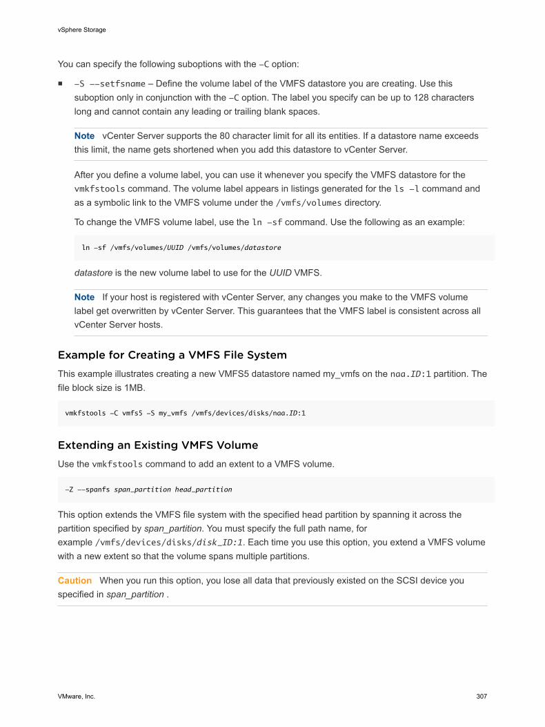
You can specify the following suboptions with the -C option:
n -S --setfsname – Define the volume label of the VMFS datastore you are creating. Use thissuboption only in conjunction with the -C option. The label you specify can be up to 128 characterslong and cannot contain any leading or trailing blank spaces.
Note vCenter Server supports the 80 character limit for all its entities. If a datastore name exceedsthis limit, the name gets shortened when you add this datastore to vCenter Server.
After you define a volume label, you can use it whenever you specify the VMFS datastore for thevmkfstools command. The volume label appears in listings generated for the ls -l command andas a symbolic link to the VMFS volume under the /vmfs/volumes directory.
To change the VMFS volume label, use the ln -sf command. Use the following as an example:
ln -sf /vmfs/volumes/UUID /vmfs/volumes/datastore
datastore is the new volume label to use for the UUID VMFS.
Note If your host is registered with vCenter Server, any changes you make to the VMFS volumelabel get overwritten by vCenter Server. This guarantees that the VMFS label is consistent across allvCenter Server hosts.
Example for Creating a VMFS File SystemThis example illustrates creating a new VMFS5 datastore named my_vmfs on the naa.ID:1 partition. Thefile block size is 1MB.
vmkfstools -C vmfs5 -S my_vmfs /vmfs/devices/disks/naa.ID:1
Extending an Existing VMFS VolumeUse the vmkfstools command to add an extent to a VMFS volume.
-Z --spanfs span_partition head_partition
This option extends the VMFS file system with the specified head partition by spanning it across thepartition specified by span_partition. You must specify the full path name, forexample /vmfs/devices/disks/disk_ID:1. Each time you use this option, you extend a VMFS volumewith a new extent so that the volume spans multiple partitions.
Caution When you run this option, you lose all data that previously existed on the SCSI device youspecified in span_partition .
vSphere Storage
VMware, Inc. 307
Example for Extending a VMFS VolumeIn this example, you extend the logical file system by allowing it to span to a new partition.
vmkfstools -Z /vmfs/devices/disks/naa.disk_ID_2:1 /vmfs/devices/disks/naa.disk_ID_1:1
The extended file system spans two partitions—naa.disk_ID_1:1 and naa.disk_ID_2:1. In thisexample, naa.disk_ID_1:1 is the name of the head partition.
Growing an Existing ExtentInstead of adding a new extent to a VMFS datastore, you can grow an existing extent using thevmkfstools -G command.
Use the following option to increase the size of a VMFS datastore after the underlying storage had itscapacity increased.
-G --growfs device device
This option grows an existing VMFS datastore or its extent. For example,
vmkfstools --growfs /vmfs/devices/disks/disk_ID:1 /vmfs/devices/disks/disk_ID:1
Upgrading a VMFS DatastoreIf you use a VMFS3 datastore, you must upgrade it to VMFS5.
Caution The upgrade is a one-way process. After you have converted a VMFS3 datastore to VMFS5,you cannot revert it back.
When upgrading the datastore, use the following command: vmkfstools -T|--upgradevmfs /vmfs/volumes/UUID
Note All hosts accessing the datastore must support VMFS5 . If any ESX/ESXi host version 4.x orearlier is using the VMFS3 datastore, the upgrade fails and the Mac address of the host that is activelyusing the datastore is displayed.
Virtual Disk OptionsVirtual disk options allow you to set up, migrate, and manage virtual disks stored in VMFS and NFS filesystems. You can also perform most of these tasks through the vSphere Web Client.
Supported Disk FormatsWhen you create or clone a virtual disk, you can use the -d --diskformat suboption to specify theformat for the disk.
vSphere Storage
VMware, Inc. 308
Choose from the following formats:
n zeroedthick (default) – Space required for the virtual disk is allocated during creation. Any dataremaining on the physical device is not erased during creation, but is zeroed out on demand at a latertime on first write from the virtual machine. The virtual machine does not read stale data from disk.
n eagerzeroedthick – Space required for the virtual disk is allocated at creation time. In contrast tozeroedthick format, the data remaining on the physical device is zeroed out during creation. It mighttake much longer to create disks in this format than to create other types of disks.
n thin – Thin-provisioned virtual disk. Unlike with the thick format, space required for the virtual diskis not allocated during creation, but is supplied, zeroed out, on demand at a later time.
n rdm:device – Virtual compatibility mode raw disk mapping.
n rdmp:device – Physical compatibility mode (pass-through) raw disk mapping.
n 2gbsparse – A sparse disk with 2GB maximum extent size. You can use disks in this format withhosted VMware products, such as VMware Fusion, Player, Server, or Workstation. However, youcannot power on sparse disk on an ESXi host unless you first re-import the disk with vmkfstools in acompatible format, such as thick or thin.
See Migrate Virtual Machines Between Different VMware Products.
NFS Disk Formats
The only disk formats you can use for NFS are thin, thick, zeroedthick and 2gbsparse.
Thick, zeroedthick and thin formats usually behave the same because the NFS server and not theESXi host determines the allocation policy. The default allocation policy on most NFS servers is thin.However, on NFS servers that support Storage APIs - Array Integration, you can create virtual disks inzeroedthick format. The reserve space operation enables NFS servers to allocate and guaranteespace.
For more information on array integration APIs, see Chapter 23 Storage Hardware Acceleration.
Creating a Virtual DiskUse the vmkfstools command to create a virtual disk.
-c --createvirtualdisk size[kK|mM|gG]
-a --adaptertype [buslogic|lsilogic|ide|lsisas|pvscsi] srcfile
-d --diskformat [thin|zeroedthick|eagerzeroedthick]
-W --objecttype [file|vsan|vvol]
--policyFile fileName
This option creates a virtual disk at the specified path on a datastore. Specify the size of the virtual disk.When you enter the value for size, you can indicate the unit type by adding a suffix of k (kilobytes), m(megabytes), or g (gigabytes). The unit type is not case sensitive. vmkfstools interprets either k or K tomean kilobytes. If you don’t specify a unit type, vmkfstools defaults to bytes.
vSphere Storage
VMware, Inc. 309

You can specify the following suboptions with the -c option.
n -a specifies the controller that a virtual machine uses to communicate with the virtual disks. You canchoose between BusLogic, LSI Logic, IDE, LSI Logic SAS, and VMware Paravirtual SCSI.
n -d specifies disk formats.
n -W specifies whether the virtual disk is a file on VMFS or NFS datastore, or an object on a Virtual SANor Virtual Volumes datastore.
n --policyFile fileName specifies VM storage policy for the disk.
Example for Creating a Virtual DiskThis example illustrates creating a two-gigabyte virtual disk file named rh6.2.vmdk on the VMFS filesystem named myVMFS. This file represents an empty virtual disk that virtual machines can access.
vmkfstools -c 2048m /vmfs/volumes/myVMFS/rh6.2.vmdk
Initializing a Virtual DiskUse the vmkfstools command to initialize a virtual disk.
-w --writezeros
This option cleans the virtual disk by writing zeros over all its data. Depending on the size of your virtualdisk and the I/O bandwidth to the device hosting the virtual disk, completing this command might take along time.
Caution When you use this command, you lose any existing data on the virtual disk.
Inflating a Thin Virtual DiskUse the vmkfstools command to inflate a thin virtual disk.
-j --inflatedisk
This option converts a thin virtual disk to eagerzeroedthick, preserving all existing data. The optionallocates and zeroes out any blocks that are not already allocated.
Removing Zeroed BlocksUse the vmkfstools command to convert any thin, zeroedthick, or eagerzeroedthick virtual disk to a thindisk with zeroed blocks removed.
-K --punchzero
This option deallocates all zeroed out blocks and leaves only those blocks that were allocated previouslyand contain valid data. The resulting virtual disk is in thin format.
vSphere Storage
VMware, Inc. 310
Converting a Zeroedthick Virtual Disk to an Eagerzeroedthick DiskUse the vmkfstools command to convert any zeroedthick virtual disk to an eagerzeroedthick disk.
-k --eagerzero
While performing the conversion, this option preserves any data on the virtual disk.
Deleting a Virtual DiskThis option deletes a virtual disk file at the specified path on the VMFS volume.
-U --deletevirtualdisk
Renaming a Virtual DiskThis option renames a virtual disk file at the specified path on the VMFS volume.
You must specify the original file name or file path oldName and the new file name or file path newName.
-E --renamevirtualdisk oldName newName
Cloning or Converting a Virtual Disk or RDMUse the vmkfstools command to create a copy of a virtual disk or raw disk you specify.
A non-root user is not allowed to clone a virtual disk or an RDM. You must specify the original file name orfile path oldName and the new file name or file path newName.
-i|--clonevirtualdisk oldName newName
-d|--diskformat [thin|zeroedthick|eagerzeroedthick|rdm:device|rdmp:device]
-W|--objecttype [file|vsan|vvol]
--policyFile fileName
-N|--avoidnativeclone
Use the following suboptions to change corresponding parameters for the copy you create.
n -d|--diskformat specifies disk formats.
n -W|--objecttype specifies whether the virtual disk is a file on a VMFS or NFS datastore, or anobject on a Virtual SAN or Virtual Volumes datastore.
n --policyFile fileName specifies VM storage policy for the disk.
By default, ESXi uses its native methods to perform the cloning operations. If your array supports thecloning technologies, you can off-load the operations to the array. Specify the -N|--avoidnativecloneoption to avoid the ESXi native cloning.
vSphere Storage
VMware, Inc. 311
Example: Example for Cloning or Converting a Virtual Disk
This example illustrates cloning the contents of a master virtual disk from the templates repository to avirtual disk file named myOS.vmdk on the myVMFS file system.
vmkfstools -i /vmfs/volumes/myVMFS/templates/gold-master.vmdk /vmfs/volumes/myVMFS/myOS.vmdk
You can configure a virtual machine to use this virtual disk by adding lines to the virtual machineconfiguration file, as in the following example:
scsi0:0.present = TRUE
scsi0:0.fileName = /vmfs/volumes/myVMFS/myOS.vmdk
If you want to convert the format of the disk, use the -d|--diskformat suboption.
This suboption is useful when you import virtual disks in a format not compatible with ESXi, for example2gbsparse format. After you convert the disk, you can attach this disk to a new virtual machine you createin ESXi.
For example:
vmkfstools -i /vmfs/volumes/myVMFS/templates/gold-master.vmdk /vmfs/volumes/myVMFS/myOS.vmdk -d thin
Example for Cloning or Converting a Virtual DiskThis example illustrates cloning the contents of a master virtual disk from the templates repository to avirtual disk file named myOS.vmdk on the myVMFS file system.
vmkfstools -i /vmfs/volumes/myVMFS/templates/gold-master.vmdk /vmfs/volumes/myVMFS/myOS.vmdk
You can configure a virtual machine to use this virtual disk by adding lines to the virtual machineconfiguration file, as in the following example:
scsi0:0.present = TRUE
scsi0:0.fileName = /vmfs/volumes/myVMFS/myOS.vmdk
If you want to convert the format of the disk or change the adapter type, use the -d|--diskformat andthe -a|--adaptertype suboptions. For example:
vmkfstools -i /vmfs/volumes/myVMFS/templates/gold-master.vmdk /vmfs/volumes/myVMFS/myOS.vmdk -d thin -
a buslogic
Migrate Virtual Machines Between DifferentVMware ProductsTypically, you use VMware Converter to migrate virtual machines from other VMware products into yourESXi system. However, you can use the vmkfstools -i command to import virtual disks in 2gbsparseformat into ESXi and then attach this disk to a new virtual machine you create in ESXi.
vSphere Storage
VMware, Inc. 312
You must import the virtual disk first because you cannot power on disks in 2gbsparse format on the ESXihost.
Procedure
1 Import a disk in 2gbsparse format into the ESXi host by running the following command. Make sure toselect the disk format compatible with ESXi.
vmkfstools -i <input> <output> -d <format>
2 Use the vSphere Web Client to attach the disk you imported to a virtual machine in ESXi.
For information, see the vSphere Virtual Machine Administration.
Extending a Virtual DiskThis option extends the size of a disk allocated to a virtual machine after the virtual machine has beencreated.
-X --extendvirtualdisk newSize [kK|mM|gG]
You must power off the virtual machine that uses this disk file before you enter this command. You mighthave to update the file system on the disk so the guest operating system can recognize and use the newsize of the disk and take advantage of the extra space.
Note You cannot hot-extend virtual SATA disks, or any virtual disk if the capacity after extension is equalto or greater than 2TB.
You specify the newSize parameter in kilobytes, megabytes, or gigabytes by adding a k (kilobytes), m(megabytes), or g (gigabytes) suffix. The unit type is not case sensitive. vmkfstools interprets either k orK to mean kilobytes. If you don’t specify a unit type, vmkfstools defaults to kilobytes.
The newSize parameter defines the entire new size, not just the increment you add to the disk.
For example, to extend a 4g virtual disk by 1g, enter: vmkfstools -X 5g disk name.
You can extend the virtual disk to the eagerzeroedthick format by using the -d eagerzeroedthickoption.
Note Do not extend the base disk of a virtual machine that has snapshots associated with it. If you do,you can no longer commit the snapshot or revert the base disk to its original size.
Upgrading Virtual DisksThis option converts the specified virtual disk file from ESX Server 2 format to the ESXi format.
-M --migratevirtualdisk
vSphere Storage
VMware, Inc. 313
Creating a Virtual Compatibility Mode Raw Device MappingThis option creates a Raw Device Mapping (RDM) file on a VMFS volume and maps a raw LUN to thisfile. After this mapping is established, you can access the LUN as you would a normal VMFS virtual disk.The file length of the mapping is the same as the size of the raw LUN it points to.
-r --createrdm device
When specifying the device parameter, use the following format:
/vmfs/devices/disks/disk_ID:P
Example for Creating a Virtual Compatibility Mode RDMIn this example, you create an RDM file named my_rdm.vmdk and map the disk_ID raw disk to that file.
vmkfstools -r /vmfs/devices/disks/disk_ID my_rdm.vmdk
You can configure a virtual machine to use the my_rdm.vmdk mapping file by adding the following lines tothe virtual machine configuration file:
scsi0:0.present = TRUE
scsi0:0.fileName = /vmfs/volumes/myVMFS/my_rdm.vmdk
Creating a Physical Compatibility Mode Raw Device MappingThis option lets you map a pass-through raw device to a file on a VMFS volume. This mapping lets avirtual machine bypass ESXi SCSI command filtering when accessing its virtual disk.This type of mappingis useful when the virtual machine needs to send proprietary SCSI commands, for example, when SAN-aware software runs on the virtual machine.
-z --createrdmpassthru device
After you establish this type of mapping, you can use it to access the raw disk just as you would any otherVMFS virtual disk.
When specifying the device parameter, use the following format:
/vmfs/devices/disks/disk_ID
vSphere Storage
VMware, Inc. 314
Listing Attributes of an RDMThis option lets you list the attributes of a raw disk mapping.
-q --queryrdm
This option prints the name of the raw disk RDM. The option also prints other identification information,like the disk ID, for the raw disk.
Displaying Virtual Disk GeometryThis option gets information about the geometry of a virtual disk.
-g --geometry
The output is in the form: Geometry information C/H/S, where C represents the number of cylinders, Hrepresents the number of heads, and S represents the number of sectors.
Note When you import virtual disks from hosted VMware products to the ESXi host, you might see adisk geometry mismatch error message. A disk geometry mismatch might also be the cause of problemsloading a guest operating system or running a newly-created virtual machine.
Checking and Repairing Virtual DisksUse this option to check or repair a virtual disk in case of an unclean shutdown.
-x , --fix [check|repair]
Checking Disk Chain for ConsistencyWith this option, you can check the entire disk chain. You can determine if any of the links in the chain arecorrupted or any invalid parent-child relationships exist.
-e --chainConsistent
Storage Device OptionsDevice options allows you to perform administrative task for physical storage devices.
vSphere Storage
VMware, Inc. 315
Managing SCSI Reservations of LUNsThe -L option lets you reserve a SCSI LUN for exclusive use by the ESXi host, release a reservation sothat other hosts can access the LUN, and reset a reservation, forcing all reservations from the target to bereleased.
-L --lock [reserve|release|lunreset|targetreset|busreset] device
Caution Using the -L option can interrupt the operations of other servers on a SAN. Use the -L optiononly when troubleshooting clustering setups.
Unless specifically advised by VMware, never use this option on a LUN hosting a VMFS volume.
You can specify the -L option in several ways:
n -L reserve – Reserves the specified LUN. After the reservation, only the server that reserved thatLUN can access it. If other servers attempt to access that LUN, a reservation error results.
n -L release – Releases the reservation on the specified LUN. Other servers can access the LUNagain.
n -L lunreset – Resets the specified LUN by clearing any reservation on the LUN and making theLUN available to all servers again. The reset does not affect any of the other LUNs on the device. Ifanother LUN on the device is reserved, it remains reserved.
n -L targetreset – Resets the entire target. The reset clears any reservations on all the LUNsassociated with that target and makes the LUNs available to all servers again.
n -L busreset – Resets all accessible targets on the bus. The reset clears any reservation on all theLUNs accessible through the bus and makes them available to all servers again.
When entering the device parameter, use the following format:
/vmfs/devices/disks/disk_ID:P
Breaking Device LocksThe -B option allows you to forcibly break the device lock on a particular partition.
-B --breaklock device
When entering the device parameter, use the following format:
/vmfs/devices/disks/disk_ID:P
You can use this command when a host fails in the middle of a datastore operation, such as grow extent,add extent, or resignaturing. When you issue this command, make sure that no other host is holding thelock.
vSphere Storage
VMware, Inc. 316